Integrated Wellbore Integrity Analysis Program for CO
46
U.S. Department of Energy National Energy Technology Laboratory Mastering the Subsurface Through Technology Innovation, Partnerships and Collaboration: Carbon Storage and Oil and Natural Gas Technologies Review Meeting August 13-16, 2018 Integrated Wellbore Integrity Analysis Program for CO 2 Storage Applications: Project Results DE-FE0026585 J.R. Sminchak Battelle, Columbus, Ohio, USA
-
Upload
khangminh22 -
Category
Documents
-
view
0 -
download
0
Transcript of Integrated Wellbore Integrity Analysis Program for CO

U.S. Department of EnergyNational Energy Technology Laboratory
Mastering the Subsurface Through Technology Innovation, Partnerships and Collaboration:Carbon Storage and Oil and Natural Gas Technologies Review Meeting
August 13-16, 2018
Integrated Wellbore Integrity Analysis Program for CO2 Storage Applications:
Project ResultsDE-FE0026585
J.R. SminchakBattelle, Columbus, Ohio, USA

Presentation Outline
2
1) Technical Status All technical tasks complete, project ends Sept. 2018.
2) Accomplishments to Date Evaluated subsurface conditions at 3 field sites with CO2 wells. Surveyed 1,500 CO2 wells at field sites, measured casing pressure in 53 wells,
tested 23 wells for sustained casing pressure buildup. Evaluated potential for geochemical cement sealing based on subsurface conditions
at the 3 field sites and 4 test study areas.
3) Lessons Learned No significant well defects exhibited in the subsample of wells tested, geochemical
cement sealing potential was not very sensitive to subsurface conditions at field sites, tested wells had high construction standards.
4) Synergy Opportunities5) Project Summary• Appendix Material
0 10000 20000 30000 40000
Meters
All locations approximate.
-505101520253035404550556065
%CO2

3
Acknowledgements• The project was funded by the U.S. DOE / National Energy Technology
Laboratory under their program on technologies to ensure permanent geologic carbon storage (Contract DE-FE0026585). Project Manager – William O’Dowd, NETL.
• Project team includes Battelle (Lead), Core Energy, West Virginia Geologic and Economic Survey (WVGES), Petroleum Technology Resource Center (PTRC) for SCP testing and well construction analysis Williston Basin.

4
Disclaimer• This report was prepared as an account of work sponsored by an
agency of the United States Government. Neither the United States Government nor any agency thereof, nor any of their employees, makes any warranty, express or implied, or assumes any legal liability or responsibility for the accuracy, completeness, or usefulness of any information, apparatus, product, or process disclosed, or represents that its use would not infringe privately owned rights. Reference herein to any specific commercial product, process, or service by trade name, trademark, manufacturer, or otherwise does not necessarily constitute or imply its endorsement, recommendation, or favoring by the United States Government or any agency thereof. The views and opinions of authors expressed herein do not necessarily state or reflect those of the United States Government or any agency thereof.

Technical Status- Objectives
5
• Geologic CO2 storage may affect legacy oil and gas wells.
• How would exposure to CO2 in the deep subsurface affect these wells?
• What can we learn from testing and monitoring CO2 wells?
• Are wells exposed to CO2 in any better/worse condition than typical oil and gas wells?
• Are subsurface conditions suitable for cement sealing at typical CO2 storage sites?
You are here

6
• Objective: develop & validate a program for identifying and characterizing wellbore integrity in legacy oil and gas wells for CO2 storage applications based on analytics of well records validated with sustained casing pressure testing.1. Determine the nature of well defects, location within the borehole,
and severity of the well defects via SCP tests on CO2 wells.
2. Integrate results with analysis of wells exposed to CO2 at study areas in Michigan Basin, Appalachian Basin, & Williston Basin.
• Project results will provide predictive methods to survey, identify, characterize, and manage wellbore integrity for CO2 storage applications.
Local
Regional
Technical Status- Objectives

7
• 3 year project from October 2015-September 2018 divided into 6 main technical tasks.
• Project team includes Battelle (Lead), Core Energy, PTRC (well testing in Williston Basin), and the West Virginia Geologic and Economic Survey (WVGES).
CompleteComplete
Technical Status- Objectives
J.B. Hawkins

8
• Test selected CO2 wells at 2-3 sites for sustained casing pressure response.
• Analyze casing pressure buildup to estimate the nature, depth, and severity of well defects. This testing provides direct measurement combined well defects.
• Compare test results to geochemical analysis to understand cement sealing conditions in the subsurface.
• Analyze this information to better understand interactions of legacy boreholes and CO2 storage in the subsurface.
Technical Status- Objectives

9
Technical Status- Well Integrity Registry• Well registry developed to identify wellbore integrity issues,
and where and how they occur in the subsurface.• Many possible types of well defects, combined defects may
be expressed as annulus casing pressure at wellhead.

Well Construction
• Methods• Materials
Well Casing
• Corrosion/wear• Leaks
Well Cement
• Contamination• Defects
Geologic Processes
• Geomechanical• Geochemical
CO2 Environments
• Influence of CO2 of cement, casing, etc.
10
Technical Status- Well Record Data Collection & Review• The 3 field study areas were characterized with a log and
testing based process. 5 subtasks defined:
• The 3 field study areas were characterized with this process.

• 3 study areas were examined, because they had existing oil and gas wells exposed to CO2.
• Study areas were characterized in terms of geology, well construction, field production, & CO2 exposure.
Tertiary Site
11
Technical Status- SCP Field Sites

1. Michigan Basin site • 100’s existing wells
circa 1960-2016.• 20-30 wells available in
CO2 EOR fields. • 5-30% CO2 in Antrim
Shale, 300-500 m. • 95-99% CO2 in EOR
zone at 1,500-2,000 m.
Antrim Shale CO2 % in Produced Gas Volume
(Source: Goodman et al, 2014)
12
Antrim Shale CO2 %
Antrim ShaleNiagaran
Technical Status- Field Sites

CH4CO2
OilCO2
1. Michigan Basin site • High natural CO2 levels in a
relatively shallow (350 m) shale gas play, and a deeper (1,850 m) carbonate reef CO2 enhanced oil recovery field.
13
1971 1977 1982 1988 1993 1998 2009 2015Date
Technical Status

2. Appalachian Basin site• High natural CO2 levels in
a sandstone reservoir at ~1,900 m depth.
• 20-83% natural CO2 in areas of the field.
• 58 wells circa 1960-2003.
14
Technical Status

2. Appalachian Basin site• Wells exposed to natural
CO2 accumulation at depth of 6,200 ft (1,900 m) in the Tuscarora sandstone.
Tubi
ng-P
acke
r not
sho
wn
Typical Field Well
15
Technical Status

3. Williston Basin site• ~3,000 wells, and 1,425 were
examined in this study.• The wells were primarily oil
producers with select wells used for H2O or CO2 injection from 2000-present.
• Well studied site, and previous research was used for most of this sites characterization.
16
Technical Status

17
3. Williston Basin site • Well age ranges from
1950s to 2000s.• EOR zone at 1,500 m.• Carbonate reservoir with
anhydrite caprock
Williston basin reservoir rock thin section 40X magnification(Braunberger et al., 2012).
Technical Status

• Well defects may result in “sustained casing pressure” or vent flow gas.
• Gas migrates through casing/cement into deep/production ‘B’ annulus.
• Pressure vs time and rate vs time can be analyzed for information on nature of defect, severity, and location.
Pres
sure
(psi
)
Time (hours)18
Technical Status- SCP testing

• SCP testing procedure: Confirm wellhead configuration!
Measure initial pressure on b-annulus
Vent gas and measure gas volume
Collect gas sample for analysis
Install pressure/temp logger
Log pressure build-up (1-8 weeks)
Remove logger
Analyze results
• No interruption in well operations!
19
Ex. Pressure Build-Up Monitoring
Technical Status- SCP testing

Rate Change Model
Time (days)
Pres
sure
(psi
)Pr
essu
re R
ate
(psi
/d)
20
• SCP Rate change model analysis
Technical Status- SCP testing

• SCP testing equipment and methods are fairly routine for gas storage field operators.
21
Technical Status- SCP testing

• Sustained casing pressure testing kits were constructed to test wells using methodology by Dotson et al., 2015.
• Allows operators to test many wells exposed to CO2.
22
Technical Status- SCP testing

1. MI Basin Site• 23 CO2 EOR wells circa 1960-2003 were
surveyed and measured for casing pres.• 6 wells identified with some indicators of
potential SCP.
23
Technical Status- SCP testing

1. Michigan Basin Site• 6 wells were tested for SCP.• No significant pressure rebound
observed, mostly temperature fx.
24
Technical Status- SCP testing

1. Michigan Basin Site• All pressures were <100 psi.• Pressure did not rebound to
initial levels in many wells.
25
Technical Status- SCP testing

26
2. Appalachian Basin site- field sold to new operator during the project, and the site was not available for SCP testing.• Well history/record review/discussions
with the field’s well technician indicates these wells did not have any more problems than typical oil & gas wells.
Technical Status- SCP testing

3. Williston Basin site- 1,425 wells were examined.• 30 wells with history of casing pressure were measured for
casing pressure in the field under this study.• 17 wells were tested for SCP buildup.
27
Technical Status- SCP testing

28
3. Williston Basin Site- The 17 tested wells showed minor pressure buildup less than 100 psi. This suggests wells had zonal isolation, shallow, secondary gas source. 6 wells had some pressure buildup pattern further analyzed.
Ex. WB-17 Showing nominal 15-20 psi SCP.WB-1 thru WB-16 pressure/temp. buildup
Technical Status- SCP testing

29
3. Williston Basin Site- Analysis results were inconclusive, supports operator observations that there is low gas flow from a shallow source and likely water present in the casing annulus.
Example:
Technical Status- SCP tests

Subsurface cement sealing conditions?
30
• 1,500 CO2 wells were reviewed, 53 well casing pressures were measured, and 23 wells were tested for SCP buildup. No positives for SCP well defects were found.
• Therefore, additional task on statistical machine based learning was revised to examine cement sealing conditions. What construction practices were used in these
CO2 wells that may have ensured wellbore integrity? Were conditions right for CaCO3 mineralization in the
cement annulus, leading to sealing conditions? Are these sealing conditions likely to be present in
other oil and gas fields?
Technical Status- Field Analysis of Geochemical Cement Sealing Conditions Reservoir/Caprock Mineralogy
Cement Sample
Brine Geochemistry

31
• Analysis of Subsurface Setting for Cement Sealing Field site conditions vary in depth, age, pressure, temperature, well
construction, & CO2 exposure Reservoirs–sandstone/carbonates, caprock–shale & evaporite Highly saline brine in both Appalachian & Michigan Basins Standard Portland Class A cement used at all 3 sites
Technical Status- Geochemical Analysis
Parameter Appalachian Basin
Michigan Basin
Williston Basin
Field Area (acre) 30,000 3,000 45,000 Reservoir Depth (ft) 6,200-7,000 1,000 & 6,000 5,000 Reservoir Type Sandstone Carbonate Reefs Carbonate Caprock Shale/Carbonate Evaporite Evaporite CO2 Type Natural gas & CO2 CO2 EOR CO2 WAG EOR Temperature (°F) 140 105 145 Discovery Pressure (psi) 2,900 3,000 2,000 Discovery Year 1973 1960 1954 # Wells 58 ~45 ~3,000
Ex. Tuscarora Sandstonefrom Appalachian Basin site
(6730-6750 ft)

32
Technical Status- Geochemical Analysis
• Equilibrium Model – Appalachian Basin • Equilibrium Model – Michigan Basin
-60
-50
-40
-30
-20
-10
0
10Minimum Midpoint Maximum
Log
Satu
ratio
n In
dice
s
Calcite Aragonite Vaterite WollastonitePortlandite Ca2SiO4 Hatrurite Ca4Al2Fe2O10Ettringite CSH0.8 CSH1.2 CSH1.6Friedel's Salt
-60
-50
-40
-30
-20
-10
0
10Minimum Midpoint Maximum
Log
Satu
ratio
n In
dice
s
Calcite Aragonite Vaterite WollastonitePortlandite Ca2SiO4 Hatrurite Ca4Al2Fe2O10Ettringite CSH0.8 CSH1.2 CSH1.6Friedel's Salt
• PHREEQC modeling for Appalachian and Michigan Basin Equilibrium model – saturation indices at equilibrium
Equilibrium phases – moles of minerals precipitated at equilibrium
Solid equilibrium phases – effect of solids (reservoir rock, caprock, cement)
CO2 batch – Changes with the addition of CO2
Reservoir conditions batch – pH, pe, P and T varied independently.

33
CO2 Batch – moles of mineral phases
-5
0
5
10
15
0.001
0.01
0.1
1
10
1000 10 20 30 40 50
pH o
r pe
Mol
es o
f min
eral
pha
ses
CO2 added (moles)
Calcite Aragonite Vaterite WollastonitePortlandite Ca2SiO4 Hatrurite Ca4Al2Fe2O10 Ettringite CSH0.8 CSH1.2 CSH1.6Friedel's Salt pH pe
Technical Status- Geochemical Analysis• Indicator Analysis for CO2 Cement Sealing Conditions Geochemical modeling completed using combination of models
designed to simulate initial conditions, the addition of CO2, and variations in reservoir properties/conditions Cement is the most reactive component of system, similar to other
research on CO2 interactions with cement Carbonation of cement reactions may seal defects, but most
typical defects detectable by logging are >50 mm aperture
Ex. Isolation Scanner Cement Log from MI Basin Site showing 210 mm fracture in cement
34
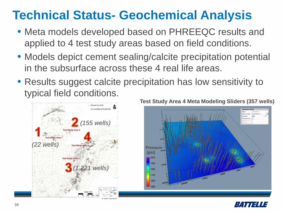
Test Study Area 4 Meta Modeling Sliders (357 wells)
Pressure(psi)
• Meta models developed based on PHREEQC results and applied to 4 test study areas based on field conditions.
• Models depict cement sealing/calcite precipitation potential in the subsurface across these 4 real life areas.
• Results suggest calcite precipitation has low sensitivity to typical field conditions.
(22 wells)
(155 wells)
(1,221 wells)
Technical Status- Geochemical Analysis

Accomplishments to Date
35
• All technical Tasks complete: Task 2- Well integrity registry to identify processes that may affect
wellbore integrity at CO2 storage sites.
Task 3- Site characterization of geology, well construction, field history, well status, for test study areas in Appalachian Basin, Michigan Basin, and Williston Basin.
Task 4- Log and testing based wellbore integrity assessment
Task 5- Completed sustained casing pressure testing and analysis for Michigan Basin site and Williston Basin Site.
Task 6- Field analysis of CO2 cement sealing and well integrity
Task 7- Wellbore integrity sealing conditions uncertainty analysis
• Final Technical Report September 2018

36
• 3 field sites with CO2 wells were examined.• Surveyed 1,500 CO2 wells at field sites, measured casing
pressure in subsample of 53 wells, tested 23 wells for sustained casing pressure buildup.
• No significant well defects exhibited in the subsample of wells tested, wells exhibited zonal isolation with no indication of significant well defects.
• Task 6-7 modified to evaluate potential for geochemical cement sealing based on subsurface conditions at the 3 field sites and 4 test study areas.
• Geochemical cement sealing potential was not very sensitive to subsurface conditions at field sites.
Lessons Learned

Lessons Learned
37
• Results were not expected, we expected to see some defects in wells (like O&G wells tested in other projects).
• Well construction methods that appear to have helped maintain wellbore integrity at the site include: Multiple strings of casing (conductor, surface, intermediate, and
deep) were present in the wells, reducing potential for gas migration. Most wells were cemented across or near casing string crossovers
reducing pathways for gas migration along the boreholes. More cement was used to cement in the casing strings than many
other areas of the Midwest. Casing strings were cemented with several hundred feet of cement (in many cases over 1,000 ft).
• Future work may examine long-term life cycle conditions in CO2 well with periodic CBLs, SCP tests.

Synergy Opportunities
38
• Project has significant synergies with other ongoing work on carbon storage technologies (carbon capture & storage), shale gas developments, other CO2 storage research.
• Provides a better understanding of wellbore integrity in legacy oil and gas wells, a key issue for CO2 storage in the region’s deep rock formations.
• Reduces uncertainty related to siting CO2 storage projects by providing direct testing of legacy CO2 wells and relating this to >1 million oil and gas wells in the region.

Project Summary
39
• This integrated approach brings together analysis of well information with field monitoring and testing: Development of a registry of wellbore integrity factors,
Detailed review of fields (Michigan Basin, Appalachian Basin, Williston Basin) with wells exposed to CO2 in the subsurface,
Clear, direct, and cost effective field testing of wells with sustained casing pressure to determine the nature of well defects common to wells exposed to CO2,
Site specific modeling of subsurface conditions for geochemical cement sealing potential in CO2 wells.

Appendix
41

Benefit to the Program
42
• This project addresses Funding Opportunity 1240 Area of Interest 2: Wellbore Leakage Identification and Characterization.
• The project is designed to establish an effective approach to determining the location/depth, nature, and severity of well integrity issues for wells exposed to CO2 environments in the subsurface.
• Project results will provide new and improved predictive methods to survey, identify, characterize, and manage wellbore integrity defects for CO2 storage applications.

Project Overview
43
• The objective of this project is to develop and validate a program for identifying and characterizing wellbore leakage potential for CO2storage applications based on analytics of well records validated with sustained casing pressure field monitoring.
• The project will develop and advance technologies that will significantly improve the effectiveness and reduce the cost of implementing carbon storage.
• Integration of casing pressure test results with geochemical analysis of cement sealing conditions can better define CO2 well integrity issues.
• Development of an integrated program to identify, survey, measure, analyze, and remediate CO2 migration in wellbores.
• In addition, the type of well defect (micro-annulus, cracks, cement voids, and incomplete cement coverage) may be better characterized to select to the most appropriate remediation technology.

Organization Chart
44
3-Year Project; October 2015 - September 2018
J.B. Hawkins

Gantt Chart
45
BP1 BP2 BP3
Task Name FY2016 FY2017 FY2018 Q1 Q2 Q3 Q4 Q1 Q2 Q3 Q4 Q1 Q2 Q3 Q4
Task 1: Project Management & Planning 1.1 Update Project Mgmt. Plan 1.2 Project Management 1.3 Progress Reporting 1.4 Project Controls 1.5 NEPA Reporting Task 2: Well Integrity Registry 2.1 Well Construction Methods 2.2 Well Casing Integrity Issues 2.3 Well Cement Issues 2.4 Geologic Processes 2.5 CO2 Environments Task 3: Well Record Data Collection & Rev. 3.1 Cement & Drilling Records 3.2 Operational Records 3.3 Well Workover/Leakage Records Task 4: Log & Testing Based Well Int. Asmt. 4.1 Log Analysis 4.2 Well Record Analysis 4.3 Well Integrity Evaluation Task 5: Sustained Casing PressureAnalysis 5.1 SCP Field Site Description 5.2 SCP Field Data Collection 5.2 SCP Data Analysis Task 6: Well Integrity w/Machine Learning 6.1 Well Int. Regression of Well Int. Indicators 6.2 Data Analysis Algorithm Dev.w/Mach. Lrng 6.3 Meta-Modeling on Test Fields Task 7: WBI Uncertainty Factor Analysis 7.1 WBI Identification 7.3 Uncertainty Reduction Task 8: Reporting and Tech Transfer 9.1 Progress Reports 9.2 Technical Reports 9.3 Final Reporting 9.4 Project Meetings 9.4 DOE BPM
• Project is designed with a sequential series of tasks over 3 years.

Bibliography
46
• Sustained Casing Pressure Testing of CO2 Wells for Wellbore Integrity Defects: Environmental Risk Implications for Carbon Storage Projects, J.R. Sminchak and Matt Place, IEAGHG Modelling and Risk Network Meeting, 19-22 June 2018, Grand Forks, North Dakota, USA.
• Case Study on Wellbore Integrity for Two Fields with Wells Exposed to CO2 in the Subsurface in the Midwest U.S. Jacob Markiewicz, J.R. Sminchak, and Mark Moody. SPE Eastern Section Regional Meeting, 4-6 October 2017, Lexington, Kentucky.
• Is your well flat or carbonated? What sustained casing pressure testing and beer have in common. J.R. Sminchak. 11th IEAGHG Monitoring Network Meeting. June 13-15, 2017, Traverse City Michigan.
• Field Testing and Well History Analysis on Wells Exposed to CO2 in the Subsurface in the Midwest U.S., J.R. Sminchak, Mark Moody, Autumn Haagsma, Andrew Duguid, Matt Place, and Neeraj Gupta. Carbon Capture, Utilization, and Storage Conference, June 14-16, 2016, Tysons, VA, USA.
• A project overview presentation given by J.R. Sminchak at the DOE-NETL Carbon Storage Program Review Meeting in Pittsburgh, Pennsylvania, August 16-18, 2016, August 12-15, 2017, August 13-17, 2018.
• Sustained Casing Pressure Diagnosis with Extended Data Collection, Matt Place, Glenn Larsen, Bryan Dotson, Nigel Jenvey, and Mark Moody, SPE Eastern Regional Meeting, 13-15 October 2015, Morgantown, WV.
• Sustained Casing Pressure Diagnosis Using the Wellhead Model, Bryan Dotson, Mark Moody, and Matthew Place, SPE/CSGM Gas Migration Challenges – Identification and Treatment Workshop, May 13-14, 2015 Banff, Alberta, Canada.
• J.R. Sminchak, Mark Moody, Andrew Theodos, Glenn Larsen, and Neeraj Gupta. 2014. Investigation of wellbore integrity factors in historical oil and gas wells for CO2 geosequestration in the Midwestern U.S. Energy Procedia (2014), pp. 5787-5797. http://dx.doi.org/10.1016/j.egypro.2014.11.611