Instruction register sequence decoder for microprogrammed ...
199
J ) JEuropaisches Patentamt European Patent Office ® Publication number: 0 01 9 392 Office europeen des brevets B 1 <g) EUROPEAN PATENT SPECIFICATION (§) Date of publication of patent specification: 17.08.88 (§) Int. CI.4: G 06 F 9/26 (a) Application number: 80301418.2 (§) Date of filing: 30.04.80 (§) Instruction register sequence decoder for microprogrammed data processor and method. (9) Priority: 21.05.79 US 41202 (73) Proprietor: MOTOROLA, INC. 1303 East Algonquin Road Schaumburg, Illinois 60196 (US) (§) Date of publication of application: 26.1 1.80 Bulletin 80/24 ® Inventor: Tredennick, Harry Leslie 4508 Pack Saddle (§) Publication of the grant of the patent: Austin, Texas 78745 (US) 17.08.88 Bulletin 88/33 Inventor: Gunter, Thomas Glen 4505 Mountain Path Austin, Texas 78759 (US) (§) Designated Contracting States: DEFRGB (§) Representative: Newens, Leonard Eric et al F.J. CLEVELAND & CO. 40/43 Chancery Lane (§) References cited: London WC2A 1JQ (GB) US-A-3 979 729 US-A-3 990 054 US-A-4010452 US-A-4074351 US-A-4131943 PROCEEDINGS OF THE 11TH ANNUAL MICROPROGRAMMING WORKSHOP ^ „ x SIGMICRO NEWSLETTER, vol. 9, no. 4, ® References cited : December 1979, pp. 8-15, IEEE New York, COMPUTER, vol. 11, no. 6, June 1978, pp. U.S.A., S. STRITTER et al.: "Microprogrammed 56-80, Long Beach, Calif., U.S.A., N.A. implementation of a single chip ALEXANDRAS: "Bit-sliced microprocessor microprocessor" architecture" Note: Within nine months from the publication of the mention of the grant of the European patent, any person may give notice to the European Patent Office of opposition fo the European patent granted. Notice of opposition shall be filed in a written reasoned statement. It shall not be deemed to have been filed until the opposition fee has been paid. (Art. 99(1 ) European patent convention). Courier Press, Leamington Spa, England.
-
Upload
khangminh22 -
Category
Documents
-
view
1 -
download
0
Transcript of Instruction register sequence decoder for microprogrammed ...

J ) J E u r o p a i s c h e s
Patentamt
European Patent Office ® Publication number: 0 0 1 9 3 9 2
Office europeen des brevets B 1
<g) EUROPEAN PATENT SPECIFICATION
(§) Date of publication of patent specification: 17.08.88 (§) Int. CI.4: G 06 F 9 / 2 6
(a) Application number: 80301418.2
(§) Date of filing: 30.04.80
(§) Instruction register sequence decoder for microprogrammed data processor and method.
(9) Priority: 21.05.79 US 41202 (73) Proprietor: MOTOROLA, INC. 1303 East Algonquin Road Schaumburg, Illinois 60196 (US)
(§) Date of publication of application: 26.1 1.80 Bulletin 80/24
® Inventor: Tredennick, Harry Leslie 4508 Pack Saddle
(§) Publication of the grant of the patent: Austin, Texas 78745 (US) 17.08.88 Bulletin 88/33 Inventor: Gunter, Thomas Glen
4505 Mountain Path Austin, Texas 78759 (US)
(§) Designated Contracting States: DEFRGB
(§) Representative: Newens, Leonard Eric et al F.J. CLEVELAND & CO. 40/43 Chancery Lane
(§) References cited: London WC2A 1JQ (GB) US-A-3 979 729 US-A-3 990 054 US-A-4010452 US-A-4074351 US-A-4131943
PROCEEDINGS OF THE 1 1TH ANNUAL MICROPROGRAMMING WORKSHOP ^ „ x SIGMICRO NEWSLETTER, vol. 9, no. 4, ® References cited : December 1979, pp. 8-15, IEEE New York, COMPUTER, vol. 1 1, no. 6, June 1978, pp. U.S.A., S. STRITTER et al.: "Microprogrammed 56-80, Long Beach, Calif., U.S.A., N.A. implementation of a single chip ALEXANDRAS: "Bit-sliced microprocessor microprocessor" architecture" Note: Within nine months from the publication of the mention of the grant of the European patent, any person may give notice to the European Patent Office of opposition fo the European patent granted. Notice of opposition shall be filed in a written reasoned statement. It shall not be deemed to have been filed until the opposition fee has been paid. (Art. 99(1 ) European patent convention).
Courier Press, Leamington Spa, England.
I 019 3 9 2
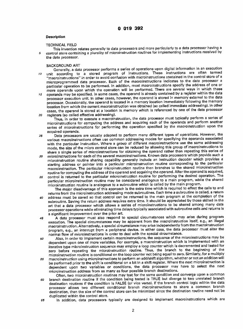
Description
TECHNICAL FIELD This invention relates generally to data processors and more particularly to a data processor having a
» control store containing a plurality of microinstruction routines for implementing instructions received by the data processor.
BACKGROUND ART Generally, a data processor performs a series of operations upon digital information in an execution
o unit according to a stored program of instructions. These instructions are often termed "macroinstructions" in order to avoid confusion with microinstructions contained in the control store of a microprogrammed data processor. Each of the macroinstructions indicates to the data processor a particular operation to be performed. In addition, most macroinstructions specify the address of one or more operands upon which the operation will be performed. There are several ways in which these
5 operands may be specified. In some cases, the operand is already contained by a register within the data processor execution unit. In other cases, however, the operand is stored in memory external to the data processor. Occasionally, the operand is located in a memory location immediately following the memory location from which the current macroinstruction was obtained (so called immediate addressing). In other cases, the operand is stored at a location in memory which is referenced by one of the data processor
io registers (so called effective addressing). Thus, in order to execute a macroinstruction, the data processor must typically perform a series of
microinstructions for computing the address and acquiring each of the operands and perform another series of microinstructions for performing the operation specified by the macroinstruction upon the acquired operands.
is Data processors are usually adapted to perform many different types of operations. However, the various macroinstructions often use common addressing modes for specifying the operands associated with the particular instruction. Where a group of different macroinstructions use the same addressing mode, the size of the micro control store can be reduced by allowing this group of 'macroinstructions to share a single series of microinstructions for obtaining the operand rather than repeating this series of
io microinstructions for each of the several macroinstructions. Known data processors which provide such a microinstruction routine sharing capability generally include an instruction decoder which provides a starting address or pointer into a particular microinstruction routine corresponding to the particular macroinstruction. The particular microinstruction routine then branches to the shared microinstruction routine for computing the address of the operand and acquiring the operand. After the operand is acquired,
35 control is returned to the particular microinstruction routine for performing the desired operation. The particular microinstruction routine may be considered analogous to a main program, while the shared microinstruction routine is analogous to a subroutine which is called by the main program.
The major disadvantage of this approach is the extra time which is required to effect the calls to and returns from the microinstruction addressing mode subroutines. Each time a subroutine is called, a return
40 address must be saved so that control can be returned to the main program at the completion of the subroutine. Saving the return address requires extra time. It should be appreciated by those skilled in the art that a data processor which allows a series of microinstructions to be shared among many data processor operations while eliminating time delays typically associated with subroutine cells and returns is a significant improvement over the prior art.
45 A data processor must also respond to special circumstances which may arise during program execution. The special circumstances may be apparent from the macroinstruction itself, e.g., an illegal macroinstruction. Alternatively, a special circumstance may arise independently from the macroinstruction program, e.g., an interrupt from a peripheral device. In either case, the data processor must alter the normal flow of microinstructions in order to deal with the special circumstance.
so Also, in order to implement certain macroinstructions, the sequence of the microinstructions may be dependent upon one of more variables. For example, a macroinstruction which is implemented with an iterative type microinstruction sequence may employ a loop counter which is decremented and tested for zero before repeating the microinstruction routine. Thus, the branch to the beginning of the microinstruction routine is conditional on the loop counter not being equal to zero. Similarly, for a multiply
55 macroinstruction using microinstructions to perform an add/shift algorithm, whether or not an addition will be performed prior to the shift is conditional on a bit in a shift register. Where the next microinstruction is dependent upon two variables or conditions, the data processor may have to select the next microinstruction address from as many as four possible branch destinations.
Often, two microinstruction routines may test for the same condition and converge upon a common 60 branch destination routine if the condition being tested is TRUE but diverge to two unrelated branch
destination routines if the condition is FALSE (or vice versa). If the branch control logic within the data processor allows two different conditional branch microinstructions to share a common branch destination, then the size of the control store can be minimized since the destination routine need not be duplicated within the control store.
65 In addition, data processors typically are designed to implement macroinstructions which are
2.

) 019 3 9 2
expressly conditioned on various condition code bits such that branching witnm tne macroinsirucuon program memory is possible (for example, a branch on condition macroinstruction). In this case, the condition to be tested is specified by the op-code of the macroinstruction. Since usually several different conditions may be tested (branch if zero, branch if overflow, branch if carry, etc.), the size of the micro
5 control store will be increased since separate microinstructions would ordinarily be required to process each of the different conditional type macroinstructions.
Thus, it should be appreciated by those skilled in the art that a data processor which includes conditional branch logic which permits different conditional branch type microinstructions to share some but not all branch destinations and which allows microinstruction routines for processing conditional type
o macroinstructions to be shared is a significant improvement over the prior art. Furthermore, a data processor generally includes an arithmetic-logic unit (ALU) for performing
arithmetical and logical operations upon digital information in order to execute a macroinstruction. Also, the condition code or status register noted above stores conditional signals reflecting the occurrence of certain conditions within the arithmetic-logic unit such as zero result, negative result, overflow generation
'5 and carry generation. In order to execute a macroinstruction, the data processor may be required to perform two or more arithmetical or logical operations. This would be true for example where iterative operations are called for such as add-and-shift routines used to execute a multiply macroinstruction. Even if the same operation is performed by the data processor in two different microcycles, the setting of the condition codes may be controlled differently during the two microcycles. If the control words in the control
20 store are required to specify all of the control signals for the operation to be performed by the ALU and for the setting of the condition codes, the control word will require a larger number of bits and thereby increase the size of the control store.
Furthermore, many macroinstructions require different ALU operations but the sequence in which these different operations are performed is the same. For example, an ADD (add) macroinstruction and a
25 SUB (substract) macroinstruction may enable the ALU on the same microcycle but perform different functions. If a separate microinstruction routine is required for ADD and SUB, the number of words in the control store is increased, again increasing the size of the control store. On the other hand, if the control store contains generalized routines which can be shared by several macroinstructions, then the size of the control store can be reduced, thereby reducing semiconductor chip area and overall cost. Those skilled in
30 the art will appreciate that a data processor which can process a wide variety of macroinstructions while minimizing the size of the control store is a significant improvement over the prior art.
It is an object of the present invention to provide a data processor and a method for controlling such a data processor, which data processor employs a plurality of internally stored microinstruction routines for executing a plurality of macroinstructions received by the data processor such that one or more
35 generalized microinstruction routines may be used by the data processor in order to execute a plurality of macroinstructions. ~
It is also an object of the present invention to reduce the time required by a data processor when branching from one microinstruction routine to another microinstruction routine in order to execute a macroinstruction received by the data processor.
40 These and other objects of the present invention are accomplished by providing a data processor and a method for controlling a data processor with the features described in claim 1 and claim 6.
The present invention provides a data processor which includes an instruction register for storing the macroinstruction to be executed, a decoder responsive to the stored macroinstruction for generating two or more starting addresses, and a selector which receives the starting addresses generated by the decoder
45 and which selects one of the starting addresses as a next address in response to one or more selection signals. The data processor also includes a control structure which receives the next address chosen by the selector and which, in response to the next address, provides an output control word for controlling execution of the stored macroinstruction. Also in response to the next address, the control structure derives the selection signals to which the selector will respond in order to select a subsequent next
so address. The decoder and selector may be adapted such that an additional starting address is provided to the selector such that the selector chooses this additional starting address regardless of the condition of the one or more selection signals generated by the control structure. The control structure may be implemented with a microprogrammed control store containing a plurality of microinstruction routines each having a corresponding starting address such that the starting addresses generated by the decoder
55 correspond to various microinstruction routines contained in the microprogrammed control store. The data processor also includes branch control logic which receives conditional branch selection
signals from the control store which can directly select the conditional signal or signals to be considered. The conditional branch selection signals can also defer selection of the conditional signals to a group of bits in a stored macroinstruction. The selected conditional signals generate an output signal according to the
60 logic state of the selected conditional signals. The branch control logic is responsive to at least one of the conditional branch selection signals for selecting one of a plurality of branch destination codes associated with the output signal generated by the selected conditional signals. The selected branch destination code is provided to the control store for determining the branch destination in the control store.
This subject-matter is claimed in the divisional application EP— A— 211962. 65 The data processor further includes a decoder which receives a macroinstruction and provides a
3

0 019 3 9 2
plurality of row selection signals. The control unit is arranged in a row/column format wherein the row is selected by the received macroinstruction while the column is selected by the control store. The row selection signals are provided to the control unit for selecting a set of control signals corresponding to a set of ALU operations and condition code settings associated with the received macroinstruction. The control
5 unit is also coupled to the control store for receiving a plurality of column selection signals which select a member of the set of control signals for selecting a particular ALU operation and condition code setting for a particular microcycle.
This subject-matter is claimed in the divisional application EP— A— 221191.
10 Brief Description of the Drawings FIG. 1 is a simplified block diagram of a data processor employing a microprogrammed control store. FIG. 2 is a more detailed block diagram of a data processor of the type shown in FIG. 1 according to a
preferred embodiment of the invention. FIG. 3 is a simplified block diagram of the execution unit used within the data processor for executing
is macroinstructions. FIG. 4 is a block diagram which illustrates the data processor shown in FIG. 2 in further detail. FIG. 5 is an expansion of a portion of the block diagram shown in FIG. 4 and illustrates an instruction
register sequence decoder within the data processor. FIG. 6 illustrates several formats for macroinstructions which are processed by the data processor.
20 FIGS. 7 A— 7D illustrate the concept of functional branching within the micro control store implemented through the use of the instruction register sequence decoder.
FIG. 8 illustrates first and second formats for microwords contained by the micro control store, the first format corresponding to direct branch type micro words and the second format corresponding to conditional branch type microwords.
25 FIG. 9 illustrates a simplified programmed logic array (PLA) structure which can be used to implement the micro control store and nano control store for the data processor.
FIGS. 10A — 10D illustrate the locations of the various microwords within the micro control store. FIGS. 11 A— 11F illustrate the control store addresses to which each of the nanowords in the nano
control store is responsive. 30 FIG. 12 is a key block which explains the microword blocks illustrated in FIGS. 13A— 13CN.
FIGS. 13A— 13CN illustrate, according to the format in the key block of FIG. 12, the sequencing information contained by each of the microwords and the control information contained within the nanoword associated with the selected microword.
FIG. 14 is a block diagram which illustrates the conditional branch logic unit used within the data 35 processor for controlling conditional branches within the control store.
FIGS. 15A— 15B illustrate circuitry for implementing the conditional branch logic unit shown in FIG. 14. FIG. 16 is a block diagram illustrating the function of an ALU and Condition Code Control unit
employed by the data processor for controlling the function of the ALU and controlling the setting of the condition codes.
40 FIG. 17 is an ALU control table which illustrates the operations which can be performed by the ALU within the execution unit.
FIG. 18 illustrates an ALU Function And Condition Code table having 15 rows and 5 columns which specify the ALU function and the manner in which the condition codes are to be controlled for various macroinstructions.
45 FIG. 19 is an ALU Function Control And Condition Code Decoder table which illustrates the relationship between the opcodes for various macroinstructions and the rows in the table shown in FIG. 18.
FIGS. 20A — 20B illustrate PLA decoding structures responsive to the macroinstruction opcode bitfields for generating row selection lines in accordance with the table shown in FIG. 19.
FIGS. 21 A— 21 B illustrate circuitry for implementing the 15-row by 5-column table shown in FIG. 18 for so generating the control signals used to specify the ALU function and to control setting of the condition
codes. FIGS. 22A— 22U are tables which illustrate the Au A2, and A3 starting addresses generated by the
instruction register sequence decoder for each of the macroinstructions.
55 DETAILED DESCRIPTION OF A PREFERRED EMBODIMENT In Fig. 1, a simplified block diagram of a data processor is shown which employs a microprogrammed
control structure to effect execution of macroinstructions received by the data processor. Instruction register 2 stores a macroinstruction received from a program memory. The stored macroinstruction is output by instruction register 2 to instruction decode block 4. Instruction decode block 4 derives
60 information from the instruction such as a function to be performed by an arithmetic-logic unit (ALU) within execution unit block 6, as well as the registers which will provide data to the ALU and the registers which will store the result formed by the ALU. Instruction decode block 4 is also coupled to a control store block 8 which provides timing and control signals to execution unit 6.
The execution of a particular macroinstruction may require several execution unit time periods, or 65 microcycles, such that various transfers and functions are performed by execution unit 6 during each of the
4

D 019 3 9 2
execution unit time periods. The timing and control signals provided by control store block 8 insure that the proper transfers and operations occur during each of the execution unit time periods.
Structural Overview of Preferred Embodiment 5 In Fig. 2, a more detailed block diagram is shown which illustrates a preferred embodiment of the
present invention. Instruction register 10 receives a macroinstruction from a program memory and stores this instruction. Instruction register 10 is coupled to control logic block 12 which extracts from the stored macroinstruction information which is static over the time period during which the stored macroinstruction is executed. Examples of macroinstruction static information are source and destination registers, ALU
to operation (addition, subtraction, multiplication, exclusive-OR), and immediate values contained within the instruction word such as address displacements and data constants.
Instruction register 10 is also coupled to instruction register sequence decoder block 14. In response to the macroinstruction stored by instruction register 10, instruction register sequence decoder 14 generates one or more starting addresses. Instruction register sequence decoder 14 is coupled to address selection
is block 16 for providing the one or more starting addresses. Line 17 couples the output of address selection block 16 to a control store which includes micro control store 18 and nano control store 20. In response to the address selected onto line 17, nano control store 20 selects a nanoword which contains field-encoded control words for directing action in the execution unit. Nano control store 20 is coupled to control logic 12 which decodes the various fields in the nano control word in combination with the macroinstruction static
20 information received directly from instruction register 10. The output of control logic 12 is coupled to execution unit 22 for controlling the various operations and data transfers which may be performed within execution unit 22.
Micro control store 18 is responsive to the selected address on line 17 for selecting a microword. Line 24 couples an output of micro control store 18 to address selection block 16 and to conditional branch
25 control logic block 26. The selected microword contains information which generally determines the source of the next micro instruction address to be selected. The selected microword may also provide the address of the next micro instruction.
Execution unit 22 stores various condition code flags which are set or reset depending upon the status of ALU operations such as positive/negative result, zero result, overflow, and carry-out. In the event that the
30 selection of the next micro instruction address is dependent upon one or more of these condition code flags, the microword provided by micro control store 18 also includes information provided to conditional branch control logic 26 for specifying which of the condition code flags will be used to determine the selection of the next micro instruction. In some cases, the macroinstruction itself specifies the condition code flags which are to be used to select the next micro instruction (for example, a conditional branch
35 ' macroinstruction such as branch on zero). For this reason, instruction register 10 is also coupled to conditional branch control logic 26. Execution unit 22 is coupled to conditional branch control logic 26 for providing the various condition code flags. Conditional branch control logic 26 is coupled to address selection block 16 for specifying a portion of the next micro instruction address.
Micro control store 18 has a second output which is coupled to line 28. The selected microword 40 includes a function code field which specifies the function of the current micro instruction. Line 28 provides
the function code field to peripheral devices external to the data processor for communicating information about the current micro instruction.
In general, instruction register sequence decoder 14 provides a starting address for micro control store 18 which then produces a sequence of addresses for the nano control store 20. The associated nanowords
45 are decoded by the control logic 12 and mixed with timing information. The resulting signals generated by control logic 12 are used to drive control points in execution unit 22.
In FIG. 3, a simplified block diagram of execution unit 22 (in FIG. 2) is shown. The execution unit is a segmented two-bus structure divided into three sections by bidirectional bus couplers. The left-most segment contains the high order word' for the address and data registers and a simple 16-bit arithmetic
50 unit. The middle segment contains the low order word for the address registers and a simple 16-bit arithmetic unit. The right-most segment contains the low order word for the data registers and an arithmetic and logic unit. The execution unit also contains an address temporary register, and a data temporary register each of which is 32 bits wide. In addition there are also several other temporary registers and special function units which are not visible to a programmer.
55 With reference to FIG. 3, a first digital bus 10' and a second digital bus 12' have been labeled ADDRESS BUS DATA and DATA BUS DATA, respectively. A group of 16-bit data registers, illustrated by block 14', is coupled to digital buses 10' and 12' such that block 14' can provide a 16-bit data word to either digital bus 10' or digital bus 12'. Similarly block 14' may receive from either bus 10' or bus 12' a 16-bit data word which is to be stored in one of the registers. It is to be understood that each of the digital buses 10' and 12' is
60 adapted for transmitting 16 bits of digital information. The 16-bit registers contained by block 14' comprise the least significant 16 bits of a corresponding plurality of 32-bit data registers.
Blocks 16' and 18' are also coupled to digital buses 10' and 12'. Block 16' contains special function units not directly available to the programmer. Among the special function units are a priority encoder, used to load and store multiple registers, and a decoder, used to perform bit manipulation. Block 18'
65 contains an arithmetic and logic unit which receives a first 16-bit input from bus 10' and a second 16-bit
5

0 019 3 9 2
input from bus 12' and generates a 16-bit result. The 16-bit result may then be transferred onto either bus 10' or bus 12'.
Also shown in FIG. 3 is a third digital bus 20' and a fourth digital bus 22'. Bus 20' and bus 22' have been labeled ADDRESS BUS LOW and DATA BUS LOW, respectively. Block 24' is coupled to both bus 20' and
5 bus 22' and contains a plurality of 16-bit address registers. These registers comprise the least significant 16 bits of a corresponding plurality of 32-bit address registers. Block 24' can provide a 16-bit address word to either bus 20' or 22'. Similarly block 24' can receive a 16-bit address word from either bus 20' or- bus 22' for storage in one of the 16-bit address registers.
Block 26' is also coupled to bus 20' and bus 22' and contains an arithmetic unit for performing 10 computations. Block 26' can receive a first 16-bit input from bus 20' and a second 16-bit input from bus 22'
and generates a 16-bit result. The 16-bit result produced by ARITHMETIC UNIT LOW 26' may be transferred onto bus 20' or onto bus 22'. ARITHMETIC UNIT LOW 26' also produces a carry-out signal (not shown) which may be used in computations involving the most significant 16 bits of a 32-bit address word. Although not shown in FIG. 3, a field translate unit (ftu) is also coupled to bus 20' and bus 22' and may be
'5 used to transfer digital information between the execution unit and other sections of the data processor. First and second bidirectional bus switches 28' and 30' are shown coupled between bus 10' and bus 20' and between bus 12' and bus 22', respectively.
Also shown in FIG. 3 is a fifth digital bus 32' and a sixth digital bus 34'. Bus 32' and bus 34' have been labeled ADDRESS BUS HIGH and DATA BUS HIGH, respectively. Block 36' is coupled to both bus 32' and
20 bus 34' and contains a plurality of 16-bit address registers and another plurality of 16-bit data registers. The address registers within block 36' comprise the most significant 16 bits of the 32-bit address registers formed in conjunction with the registers contained by block 24'. The 16-bit data registers within block 36' comprise the most significant 16 bits of a plurality of 32-bit data registers formed in conjunction with the data registers contained by block 14'.
25 Block 38' is also coupled to bus 32' and bus 34' and contains an arithmetic unit for performing computations upon the most significant 16 bits of either address or data words. Block 38' receives a first 1 6- bit input from bus 32' and a second 16-bit input from bus 34' and generates a 16-bit result. The 16-bit result produced by ARITHMETIC UNIT HIGH 38' may be transferred onto bus 32' or bus 34'. As previously mentioned, ARITHMETIC UNIT HIGH 38' can be responsive to a carry out produced by block 26' such that a
30 carry out from the least significant 16 bits is considered a carry in to the most significant 16 bits. Third and fourth bidirectional bus switches 40' and 42' are shown coupled between bus 32' and bus 20' and between bus 34' and bus 22', respectively.
Thus it may be seen that the register file for the data processor is divided into three sections. Two general buses (ADDRESS BUS, DATA BUS) connect all of the words in the register file. The register file
35 sections (HIGH, LOW, DATA) are either isolated or concatenated using the bidirectional bus switches. This permits general register transfer operations across register sections. A limited arithmetic unit is located in the HIGH and LOW sections, and a general capability arithmetic and logical unit is located in the DATA section. This allows address and data calculations to occur simultaneously. For example, it is possible to do a register-to-register word addition concurrently with a program counter increment (the program counter is
40 located adjacent to the address register words, and carry out from the ARITHMETIC UNIT LOW 26' is provided as carry in to ARITHMETIC UNIT HIGH 38'). Further details of the execution unit are set forth in co- pending application "Execution Unit For Data Processor Using Segmented Bus Structure" bearing Serial No. 961,798, filed November 17, 1978, invented by Gunter et al and assigned to the assignee of the present invention, which is hereby incorporated by reference.
45 In FIG. 4, a detailed block diagram is shown of the data processor generally illustrated in FIG. 2. A bidirectional external data bus 44 is a 16-bit bus to which the data processor is coupled for transmitting data to and receiving data from peripheral devices. The data processor includes data buffers 46 coupled between external data bus 44 and execution unit 22 for transferring data between the execution unit and the external data bus. Execution unit 22 includes drivers and decoders which are shown generally along the
so periphery of execution unit 22. Execution unit 22 is also coupled to address buffers 48 which are in turn coupled to external address bus 50. An address provided by execution unit 22 to external address bus 50 typically specifies the location from which the data on bus 44 was read or the location to which the data on bus 44 is to be written. In the preferred embodiment, external address bus 50 is 24-bits wide such that a memory addressing range of more than 16 mega-bytes is provided.
55 External data bus 44 is also coupled to the input of 16-bit IRC register 52. The output of IRC register 52 is coupled to the input of 16-bit IR register 54. The output of IR register 54 is coupled to the input of 16-bit IRD register 56. Also coupled to the output of IR register 54 are the inputs to block 58 (ADDRESS 1 DECODER) and block 60 (ADDRESS 2/3 DECODER) as well as the input to block 62 (ILLEGAL INSTRUCTION DECODER). The use of IRC register 52, IR register 54, and IRD register 56 allows the data processor to operate in a
so pipelined manner; IRC register 52 stores the next macroinstruction, and IR register 54 stores the macroinstruction currently being decoded, while IRD register 56 stores the macroinstruction currently being executed. The output of block 58 is coupled to the A, input of address selector 64. A first output of block 60 is coupled to the A2 input of address selector 64 and a second output of block 60 is coupled to the A3 input of address selector 64. The output signals provided by block 58 and block 60 are microroutine
65
6

0 019 3 9 2
starting addresses associated with a macroinstruction stored by IR register 54 as will be later explained in further detail.
The output of Illegal Instruction Decoder 62 is coupled to exception logic block 66. Also coupled to block 66 are block 68 (BUS I/O LOGIC) and block 70, (INTERRUPT AND EXCEPTION CONTROL). A first
5 output of exception logic block 66 is'coupled by line 71 to the Aq input of address selector 64 for providing a special microroutine starting address. A second output of exception logic block 66 is coupled by line 71' (AqS) to another input of address selector 64 for providing a second special microroutine starting address. Two additional outputs of exception logic block 66, A0SUB and AqSUBI, respectively, are also coupled to address selector 64.
io The output of address selector 64 is coupled to the input of micro ROM 72 and the input of nano ROM 73 for providing a selected address. The output of micro ROM 72 is coupled to micro ROM output latch 74 which stores the microword selected by micro ROM 72 in response to the address selected by address selector 64. The output of micro ROM output latch 74 is coupled to address selector 64 by lines 76 and 78 and to branch control unit 80 by line 82. Line 76 can provide a direct branch address as an input to address
ts selector 64 while line 78 can specify to address selector 64 the source of the next address to be selected. In the event of a conditional branch, line 82 specifies the manner in which branch control unit 80 is to operate. Branch control unit 80 is also coupled to address selector 64 in order to modify the selection of the next micro/nano store address in order to accomplish conditional branching in a microroutine, as will be further explained hereinafter.
20 IRD register 56 has an output coupled to branch control unit 80 for supplying branch control information directly from a macroinstruction word. Branch control unit 80 is also coupled to an output of ALU AND CONDITION CODE CONTROL block 84 for receiving various condition code flags. PSW register 86 is coupled to block 84 and stores several of the condition code flags. Execution unit 22 is also coupled to block 84 for supplying other condition code flags.
25 Still referring to FIG. 4, nano ROM 73 is coupled to nano ROM output latch 88 for supplying a nanoword associated with the address selected by address selector 64. Various bit fields of the nanoword stored by latch 88 are used to control various portions of execution unit 22. Line 90 is coupled directly from latch 88 to execution unit 22 for controlling such functions as transferring data and addresses between the execution unit 22 and external buses 44 and 50. Line 92 is coupled from latch 88 to register control block 94. IRD
30 register 56 is also coupled to register control block 94. Bit fields within IRD register 56 specify one or more registers (source, destination) which are to be used in order to implement the current macroinstruction. On the other hand, bitfields derived from latch 88 and supplied by line 92 specify the proper micro cycle during which source and destination registers are to be enabled. The output of block 94 is coupled to execution unit 22 for controlling the registers located in the HIGH section of the execution unit (block 36' in FIG. 3). In a
35 similar manner, register control block 96 also has inputs coupled to latch 88 and IRD register 56 and is coupled to execution unit 22 for controlling the registers located in the LOW and DATA sections of the execution unit.
Line 98 couples latch 88 to AU control block 100 for supplying a bit field extracted from the nano word. Block 100 is also coupled to IRD register 56. Bit fields in the macroinstruction stored by IRD register 56
40 specify an operation to be performed by the ARITHMETIC UNIT HIGH and ARITHMETIC UNIT LOW in execution unit 22 (block 38' in FIG. 3). Information supplied by line 98 specifies the proper micro cycle during which the inputs and outputs of the ARITHMETIC UNIT HIGH and ARITHMETIC UNIT LOW are enabled. The output of AU control block 100 is coupled to execution unit 22 for controlling the arithmetic units in the HIGH and LOW sections.
45 Line 102 couples latch 88 to ALU AND CONDITION CODE CONTROL block 84. IRD register 56 is also coupled to block 84. Bit fields derived from the macroinstruction stored in IRD register 56 indicate the type of operation to be performed by the ALU in execution unit 22. Bit fields derived from the nanoword stored in latch 88 specify the proper micro cycles during which the input and outputs of the ALU are to be enabled. An output of block 84 is coupled to execution unit 22 for controlling the ALU. Block 84 also provides an
50 output to PSW register 86 for controlling the condition code flags stored therein. Line 104 couples latch 88 to FIELD TRANSLATION UNIT 106. IRD register 56 is also coupled to FIELD
TRANSLATION UNIT 106. Also coupled to FIELD TRANSLATION UNIT 106 are PSW register 86 and special status word (SSW) register 108. PSW register 86 stores information such as the current priority level of the data processor for determining which interrupts will be acknowledged. PSW register 86 also specifies
55 whether or not the processor is in the TRACE mode of operation and whether the processor is currently in a supervisor or user mode. SSW register 108 is used to monitor the status of the data processor and is useful for recovering from error conditions. FIELD TRANSLATION UNIT 106 can extract a bit field from the macroinstruction stored in IRD register 56 for use by the execution unit such as supplying an offset which is to be combined with an index register. FTU 106 can also supply bit fields extracted from PSW register 86
so and SSW register 108 to the execution unit 22. FTU 106 can also be used to transfer a result from execution unit 22 into PSW register 86.
INSTRUCTION REGISTER SEQUENCE DECODER In FIG. 5, a portion of FIG. 4 which includes an instruction Register Sequence Decoder has been
65 expanded in greater detail. Blocks in FIG. 5 which correspond to those already shown in FIG. 4 have been
7

0 019 3 9 2
identified with identical reference numerals. Blocks 58, 60, and 66 are included within dashed block 110 which forms the Instruction Register Sequence Decoder. Instruction Register 54 (IR) receives a macroinstruction from a program memory via bus 44 and IRC register 52 and stores this instruction. The output of IR register 54 is coupled to illegal instruction decoder 62 which detects invalid macroinstruction
5 formats. The output of IR register 54 is also coupled to an ADDRESS 1 DECODER 58 and ADDRESS 2/3 DECODER 60. Decoders 58 and 60 are programmed logic array (PLA) structures in the preferred embodiment. PLA structures are well known by those skilled in the art. For example, see "PLAs Enhance Digital Processor Speed and Cut Component Count", by George Reyling, Electronics, August 8, 1974, p. 109. In response to the macro instruction stored by register 54, decoder 58 provides a first starting
'0 address at an output A, which is coupled to multiplexer 112. Exception logic block 66 is coupled to the output of illegal instruction decoder 62, the output of BUS I/O
logic block 68 and the output of interrupt and exception block 70. BUS I/O logic block 68 is used to detect bus and address errors. A bus error may indicate to the data processor that a peripheral device (e.g., a memory) addressed by the data processor has not responded within an allowable period of time. An
15 address error may indicate that an illegal address has been placed on the external address bus. Interrupt and exception block 70 indicates such things as the occurrence of interrupts, the occurrence
of a reset condition, and a trace mode of operation. An interrupt condition may occur when a peripheral device indicates that it is ready to transmit data to the data processor. The reset condition may indicate that the power supply to the data processor has just been activated such that internal registers must be reset or
20 that a reset button has been depressed in order to recover from a system failure. A trace mode of operation may indicate that a tracing routine is to be performed after the execution of each macroinstruction in order to facilitate instruction-by-instruction tracing of a program being debugged.
Illegal instruction decode block 62 indicates illegal macroinstruction formats as well as privilege violations. An illegal instruction format is one to which the data processor is not designed to respond. The
25 privilege violation condition refers to a feature of the data processor which allows operation in supervisor and user modes. Certain instructions may be executed only when the data processor is in a supervisor mode, and the privilege violation condition arises upon the attempted execution of one of these special instructions while in the user mode of operation.
All of the above mentioned special conditions require that the data processor temporarily stop 30 executing macroinstructions in order to execute special microinstruction routines for dealing with the
occurrence of the particular special condition. Itsome of the special conditions (e.g., interrupt, trace) arise/ the data processor proceeds normally until it reaches the next instruction boundary, i.e., the processor completes the execution of the current macroinstruction prior to branching to the special microinstruction routine. However, when other special conditions (e.g., address error, bus error, reset) arise, the data
35 processor immediately branches to one of the special microinstruction routines without completing the current macroinstruction, since the occurrence of the special condition may prevent successful execution of the current macroinstruction.
Still referring to FIG. 5, exception logic block 66 includes an output A0 which is coupled over line 71 to multiplexer 112 for supplying a special microroutine starting address. Exception logic block 66 also
40 includes output A0SUB which is coupled to multiplexer 1 12 for determining whether starting address A0 or starting address A, is to be selected as the output of multiplexer 112. Starting address Aq is selected upon the occurrence of special conditions of the type which await the completion of the execution of the current macroinstruction before causing control to be transferred to the special microinstruction routine.
The output of multiplexer 1 12 is coupled to the A^Aq input of multiplexer 114. Decoder 60, in response 45 to the macroinstruction stored by register 54, provides second and third starting addresses at output A2 and
A3 which are coupled to the A2 and A3 inputs of multiplexer 1 14, respectively. Multiplexer 114 also includes a BA input which is coupled to line 116 for receiving a branch address from the micro ROM. Each of the addresses received by multiplexer 114 is 10-bits wide.
The output of multiplexer 1 14 provides a selected address having 10-bits and is coupled to a first input so of multiplexer 1 17 for supplying two of the ten output bits. The output of multiplexer 1 14 is also coupled to
a first input of multiplexer 118 for supplying the other eight bits of the selected address directly to multiplexer 118. Branch control logic 80 is coupled to a second input of multiplexer 117 for supplying two branch bits. The output of multiplexer 117 is coupled to multiplexer 118 for supplying two selected bits to be used in conjunction with the eight bits supplied directly from multiplexer 114, thereby allowing for a
55 four-way branch. Exception logic 66 includes an output A0S which is coupled to a second input of multiplexer 118 for
supplying a second special microroutine starting address. Exception logic 66 also includes an output AqSUBI which is coupled to the control input of multiplexer 118 and which causes .special address A0S to be selected at the output of multiplexer 1 1 8 in the event that an address error, bus error, or reset condition has
60 been detected. In the absence of such a condition, multiplexer 118 provides at its output the address selected by multiplexer 114 in combination with multiplexer 117. The output of multiplexer 118 is coupled to the address input ports of the micro ROM and nano ROM (72, 73 in FIG. 4).
FIG. 5 also includes three conductors 120, 122, and 124 which are coupled to the output of the micro ROM latch (latch 74 in FIG. 4), each of the conductors receiving a bit in the selected micro word. Conductor
65 120 is coupled to a control input of multiplexer 117 for indicating a conditional branch point in the micro

D 019 3 9 2
instruction routine. Conductors 120, 122, and 124 are coupled to decoder 126, and the output of decoder 126 is coupled to a control input of multiplexer 114 for causing the proper address to be selected at the output of multiplexer 1 14. The relationship between the microword bits conducted by conductors 120, 122, and 124andthe address selected by multiplexers 114and 117 will be described in further detail hereinafter.
5 It will be sufficient to realize at this point that the signals conducted by conductors 120, 122, and 124, and the address conducted by line 116 are all derived from the microword addressed during the previous micro cycle. -
In order to understand the advantages provided by the instruction register sequence decoder, it will be helpful to describe the various types of macroinstructions which can be executed by the data processor
'O illustrated in Fig. 2. in Fig. 6, three different types of macroinstruction formats are illustrated (I, II, III). Instruction I is a register-to-register type instruction in which bits 0, 1, and 2 specify a source register (Ry) . and bits 9, 10, and 11 specify a destination register (Rx). The remainder of the bits in the 16-bit instruction word identify the type of operation to be performed (add, subtract, etc.) and identify this instruction as one which uses register-to-register type addressing.
is In instruction format II, bits 0 through 5 are an effective address field or simply an effective address (EA). The EA is composed of two 3-bit subfields which are the mode specification field and the register specification field. In general, the register specification field selects a particular register; the mode specification field determines whether the selected register is an address register or a data regsiter and also specifies the manner in which the address of the desired operand is to be computed based upon the
20 specified register. For a typical type II instruction, the EA field specifies the source operand, while bits 9, 10, and 11 specify one of the internal registers as the destination operand. JTTie remainder of the bits in the 16- bit instruction specify the type of operation to be performed and indicate that this instruction is a type II instruction.
In type III instructions, the instruction may be composed of two or more 16-bit words wherein bits 0 25 through 5 of the first 16-bit word specify the effective address of a destination operand as previously
described for type II instructions. However, the remainder of the bits in the first word of type III instructions indicate that the instruction includes a second 16-bit word which contains the data to be used in conjunction with the destination operand in order to perform the operation. Type III instructions use effective addressing to obtain the destination operand and so-called "immediate addressing" to obtain a
30 second operand which is stored in a memory location immediately following the memory location from which the first word of the instruction was obtained.
In order to execute type I instructions, the data processor can immediately begin performing a microinstruction routine specifically designed to execute the type of operation indicated by the instruction word, since the operands are already contained by internal registers of the data processor. For type II
35 instructions, however, a generalized effective address microinstruction routine must be performed in order to access the operand referenced by the EA field prior to executing a specific microinstruction routine used to perform the operation indicated by the macroinstruction. For immediate-type instructions, a pre-fetch operation results in the immediate operand being stored in both IRC register 52 and in a data bus input latch located within DATA BUFFERS block 46 (see FIG. 4). Thus, in type III instructions, a first generalized
40 microinstruction routine must be performed in order to transfer the immediate operand from the data bus input latch to a temporary register in the execution unit and in order to repeat the pre-fetch operation such that the next macroinstruction is loaded into IRC register 52. Then, the generalized routine described with regard to type II instructions must be performed in order to obtain the operand referenced by the EA field. Finally, after the EA microinstruction routine has been completed, a specific microinstruction routine must
45 be executed in order to perform the operation indicated by the first word of the instruction. The effective address microinstruction routines can be generalized because all type II and type III instructions use the same EA format. Similarly, the immediate addressing microinstruction routine can be generalized because all type III instructions access immediate operands in the same manner.
With reference to FIG. 5, the operation of decoders 58 and 60 and exception logic 66 within the so instruction register sequence decoder 110 will be described by referring to FIGs. 7A, 7B, 7C, and 7D. In
normal operation, multiplexer 114 chooses starting address A^Ao to point to the first microinstruction routine required to execute the macroinstruction presently stored in IR register 54. Starting address A^Ao is selected at instruction boundaries because the very last microinstruction performed during the execution of the previous macroinstruction indicates, by way of decoder 126, that A, should be selected as the next
55 starting address. In the event that a special condition arises during the execution of a macroinstruction, exception logic
66 enables the AoSUB output such that the multiplexer 112 will substitute starting address Aq in place of starting address A, when execution of the current macroinstruction is completed. Some of the special conditions require initiation of a special microinstruction routine without waiting for the execution of the
so previous macroinstruction to be completed. In this case, exception logic 66 enables the AoSUBI output which immediately causes starting address A0S on line 71' to be selected by multiplexer 118 as the next address for the micro control store in order to cause a branch to a special microroutine.
As shown in FIG. 7A, starting addresses Aq and AqS reference one of several special microinstruction routines in order to deal with the specific special condition that has arisen. A common feature of each of the
65 special microroutines is that the last microword in each routine causes the signals conducted by
9

0 019 3 9 2
conductors 120, 122, and 124 in FIG. 5 to specify the multiplexer 114 that starting address A, is the next address to be input to the micro control store.
As is shown in FIG. 7B, starting address A, may reference a generalized immediate routine, a generalized effective address routine, or a specific operation routine depending upon the type of
5 instruction presently stored in the instruction register. Each of these routines accomplishes a separate function, and the transfer of control from one routine to another may be referred to as functional branching. For example, starting address A-, will reference a specific operation routine if the instruction register has stored a type I instruction (see FIG. 6). In this event, the A2 and A3 addresses output by A2/A3 decoder 60 in FIG. 5 are "don't care" conditions, which simplifies the PLA structure used to implement the decoder.
io Starting address A, will reference an effective address routine or an immediate routine if the instruction stored by the instruction register is a type II instruction or a type III instruction, respectively. In addition to performing the desired operation, each of the specific operation routines is effective to transfer a prefetched macroinstruction word from IRC register 52 to IR register 54 and to fetch a subsequent macroinstruction word and store it in IRC register 52. The macroinstruction word is prefetched far enough
is in advance to ensure that the starting addresses output from A, and A2/A3 decoders 58 and 60 are valid at the appropriate time. In addition, the last microword in each of the specific operation routines specifies that starting address Af is to be selected as the next address input to the micro control store. Each of the effective address routines concludes with a microword which specifies that starting address A3 is to be selected as the next address. Starting address A3 always points to a specific operation routine, as is shown
20 in FIG. 7D. The last microword in all immediate routines causes starting address A2 to be selected as the next address.
As is shown in FIG. 7C, starting address A2 may reference either an effective address routine or a specific operation routine. A type III instruction (see FIG. 6) would result in starting address A2 causing a branch to an effective address routine. Although not shown in FIG. 6, another type of instruction may
25 require immediate addressing without also including an effective address field. For this type of instruction, starting address A2 would reference a specific operation routine.
Thus, in order to execute a type III instruction, starting address A is selected first which initiates a generalized microinstruction routine for processing an immediate operand. The last microword in the immediate microroutine selects A2 as the next starting address which causes a direct branch to an effective
30 address microroutine for acquiring a second operand. At the completion of the effective address routine, starting address A3 is selected which causes a direct branch to a microinstruction routine for performing the desired operation and for transferring the next macroinstruction into the instruction register. At the completion of the specific operation routine, starting address A, is selected in order to begin execution of the next macroinstruction.
35 In Appendix F, all of the macroinstructions which are performed by the preferred embodiment of the data processor are described. In Appendix" G, a breakdown of the op-codes is listed for ail of the macroinstructions listed in Appendix F. FIGs. 22A— 22N and 22P— 22U tabulate the starting addresses A1, A2, and A3 for each macroinstruction op-code. The starting addresses tabulated in FIGs. 22A — 22N and 22P— 22U are given in terms of the label of the microword addressed. The microword labels are tabulated
40 in Appendix A. In FIGs. 22A— 22N and 22P— 22U, the 4-bit code in the upper left corner corresponds to bits 15 — 12 of the macroinstruction. The 6-bit code to the right of each row corresponds to bits 11 — 6 of the macroinstruction. The 6-bit code at the bottom of each column corresponds to bits 5 — 0 of the macroinstruction. The columns generally correspond to the various addressing modes for each macroinstruction. RYD and RYA indicate that the operand is the contents of the designated address or data
45 register. (RYA) indicates that the address of the operand is in the designated address register. (RYA)+ and -(RYA) indicate a post-increment and pre-decrement mode wherein the designated address register is either incremented after or decremented before the operand address is usd. (RYA) + d16 and (RYA) + (X) + d8 refer to adding a 16-bit displacement to the designated address register in order to specify the operand address or adding an index register and an 8-bit displacement to the designated address register in order to
so specify the operand address. ABSW and ABSL indicate that the operand address is either the 1 6-bit word or 32-bit double-word which follows the first word of the macroinstruction in the program memory. (PC) + d16 and (PC) + (X) + d8 indicate that the operand address is either the contents of the program counter plus a 16- bit displacement or the contents of the program counter plus an index register plus an 8-bit displacement. The column labeled "#" specifies that the operand is an immediate value which may be a
55 16-bit word or a 32-bit double-word which follows the first word of the macroinstruction in the program memory.
MICROPROGRAMMED CONTROL UNIT In FIG. 4, a microprogrammed control unit is illustrated which includes micro ROM 72 and nano ROM
so 73. The micro ROM is used to direct sequencing in the control unit. Micro ROM 72 in FIG. 4 contains 544 microwords each having 17 bits. The micro ROM is addressed by the 10-bit output of address selection block 64 such that up to 1024 microwords could be addressed. However, the preferred embodiment of the data processor requires only 544 microwords. The microwords are arranged in either of two formats which are illustrated in FIG. 8. Format I in FIG. 8 is the format for all types of microwords other than those which
65 allow conditional branching, while format II is the format for microwords which provide conditional
10

I 019 3 9 2
branching. In format I, bis 1 is a "0", while in format II, bit 1 is a i sucn tnat dii i aisunguisnes ine iwu possible formats. For conditional branch type microwords (format II), bits 2 thru 6 comprise a conditional branch choice field (CBC) and specify one of 32 possible branch conditions. Also in conditional branch type microwords, bits 7 thru 14 comprise a next micro ROM base address (NMBA) for the micro and nano
r control stores. As will be explained hereinafter, the 8-bit NMBA field is augmented by 2 additional bits supplied by branch control logic in order to specify the next address for the control stores.
For microwords having format I, bits 2 and 3 comprise a type field (TY) which specifies the source of the next address for the control stores. The address is selected either from one of the 3 possible addresses provided by the instruction register sequence decoder or from a direct branch address provided by bits 5
o thru 14 of the microword which comprise a 10-bit next micro ROM address field (NMA). Referring briefly to FIG. 5, the NMA and NMBA bitfields are supplied by line 1 16 to the BA input of multiplexer 114. Conductors 120, 122 and 124 couple bits 1,2, and 3, respectively, to decoder 126 such that the proper source is selected by multiplexer 1 14 as the next address. The selection of the source of the next address is determined by the TY- field according to the table shown below.
5 t (type) bit 3 bit 2 abbrev source
0 0 db NMA
0 1 a1 Address 1
1 0 a2 Address 2
1 1 a3 Address 3 >5
Fields common to both microword formats are the function code field (FC), comprised by bits 15 and 1 6, and the load instruction field (I), corresponding to bit 0. The FC field specifies the function of the current microinstruction for peripheral devices external to the data processor. The significance of the FC field is indicated in the table below.
to bit bit
FC (function code) 16 15 abbrev operation
0 0 n No Access 35
0 0 u Unknown Access Type
0 1 d Data Access
40 1 0 i Instruction Access
1 1 a Interrupt Acknowledge
The I field (bit 0) is used to specify the micro cycle during whicn tne instruction register is to De upoaiea. 45 When bit 0 is a "1", then the output of IRC register 52 is enabled into IR register 54 (see FIG. 4). Generally,
this transfer is not made until the execution of the macroinstruction has proceeded into an operation type microroutine (FIG. 7a— 7d) such that the instruction register sequence decoder can begin to generate starting addresses for the next macroinstruction to be executed.
For microwords of the type having format II, bit 4 is included in the CBC field for selecting the 50 appropriate branch condition. However, for microwords of the type having format I, bit 4 is not included in
any of the previously described bit fields. In the preferred embodiment of the data processor, bit 4 is used in conjunction with bit 0 to control not only the loading of the instruction register but also the updating of a trap vector number (TVII) encoder. Referring briefly to FIG. 5, exception logic block 66 includes a series of latches for storing the status of the various special conditions such as interrupt pending, trace pending,
55 address error, etc. The outputs of these latches are coupled to a decoder which generates the Aq and AqS starting addresses. Two different latch enable signals are provided for independently latching two groups of these latches. The first group of latches monitors the special conditions which do not await an instruction boundary before diverting control in the micro ROM. The second group of latches monitors the remainder of the special conditions. To update the TVN encoder, both groups of latches are clocked such that the
60 output of each of these latches corresponds to the signals presented to the inputs of these latches. To partially update the TVN encoder, only one of the two clock enable signals is pulsed such that only those latches coupled to this clock enable signal are allowed to take note of signals currently presented to their inputs. For microwords of the type having format I, the loading of the instruction register and the updating of the TVN encoder are specified according to the table shown below.
55
1 1

0 019 3 9 2
c,i bit 4 bit 0 abrev result
0 0 db update neither IR nor TVN
0 1 dbi IRC to IR, update TVN
1 0 dbc IRC to IR, don't update TVN
1 1 dbl IRC to IR, partially update TVN 10
The 544 microwords stored in the micron ROM are tabulated in appendix A which follows the detailed description of the invention. The table in appendix A lists for each micro word a LABEL, the corresponding function code (FC), the associated next micro control store address (NMA) for direct branch type microwords, a TYPE for selecting the source of the next address, and a conditional branch choice (CBC) for
15 conditional branch type microwords. Also indicated in this table under the column entitled ORIGIN are instances where a microword is associated with the same nanoword in the nano control store as is a previously listed microword. The table further includes a column entitled ROW which indicates those microwords which are destinations of conditional branch type microwords. The placement of these microwords, which serve as destinations for conditional branches, is restricted since the branch address is
20 comprised of an 8-bit base address plus a 2-bit branch field generated by branch control logic. Thus, two microwords which serve as alternate destinations for a particular conditional branch type microword must be placed in the same logical row of the micro ROM. The table also includes a column entitled DESTINATIONS which lists the microwords which are potential destinations for each of the conditional branch type microwords.
25 As is shown in FIG. 4, the nano control store, or nano ROM, is addressed by the same address which is used to address the micro control store, or micro ROM. Access in the nano control store is either to a single word or a logical row of words (with subsequent conditional selection of a single word in that row). Access to the nano control store is concurrent with access to the micro control store. However, while there is a one- to-one mapping in the micro control store between addresses and unique microwords, there is a many-to-
30 one mapping of control store addresses to unique nanowords. It is possible therefore for several unique microwords to share the same nanoword.
A nanoword consists of fields of functionally encoded control signals which are decoded by the control logic (block 12 in FIG. 2) to drive the control points in the execution unit for operation of bus switches, source and destination registers, temporary locations, special function units, and input/output devices. In
35 the data processor constructed according to the preferred embodiment of the invention, each nanoword is 68 bits wide and is decoded to drive approximately 180 control points within the execution unit. The number of unique nanowords in the nano control store is 336, while the number of unique microwords in the micro control store is 544.
Since each nanoword is uniquely specified by its address, it would be possible to directly decode 40 addresses to the nano control store in order to generate control words. This would eliminate the need for
the nano control store but would greatly increase the amount of decoding logic in control block 12 of FIG. 2. At the other extreme, each control point could have an associated bit in the nanoword and no decoding of the nanoword would be necessary at ail. In practice, some chip area between the control store and the execution unit must be allocated to combine timing information and to align control word outputs with
45 associated control points within the execution unit. It is possible to provide about three gate levels of decoding in this chip area at very little cost. The control word in the preferred embodiment of the data processor is field-encoded in a manner which permits functional definition of fields and relatively simple decoding.
Minimization of the number of unique control words, or nano words, is facilitated by moving operands • so and addresses into temporary locations early in the instruction routine. This tends to make later cycles in
different instructions look more alike. Instruction set design and programming of the control unit also influence the number of nanowords. Additionally, there is a trade-off between execution efficiency and the number of unique nanowords required. The more time allowed for execution, the better the chance of making various instructions look alike.
55 In FIG. 9, circuitry is illustrated for constructing a control store having a micro ROM and a nano ROM which are addressed simultaneously by the same address. For the purpose of simplifying the illustration, the control store in FIG. 9 receives a 3-bit address which accesses a 6-bit microword in the micro ROM and an 8-bit nanoword in the nano ROM. Three address bits (A0, A,, A2) are received by conductors 128, 129, and 130 which are coupled to address conductors 131, 132, and 133, respectively. Conductors 128, 129, and
so 130 are also coupled to the inputs of inverters 134, 135, and 136, respectively. The output of inverter 134, the output of inverter 135, and the output of inverter 136 is each coupled to address conductor 137, 138, and 139, respectively. The micro ROM includes eight word lines (140 — 147) which are labeled MO thru M7 in FIG. 9. Similarly, the nano ROM includes 4 word lines (148—151) which are labeled NO thru N3. A micro ROM word line decoder is formed at the intersection of address conductors 131—133 and 137—139 and
65 micro ROM word lines 140—147. At particular intersections of an address conductor and a word line, a
12

0 019 3 9 2
bubble is illustrated such as that shown at the intersection of address conductor 139 and word line 147. The expanded drawing of the bubble at this intersection shown in FIG. 9 illustrates that a MOSFET is coupled between the word line and ground such that the word line is grounded when the address conductor is enabled. A plurality of microword columns designated generally at 152, and including column 153,
5 intersects the micro ROM word lines 140 — 147 for generating a micro ROM output word. At particular intersections of the microword columns and word lines, a bubble is indicated such as that shown at the intersection of word line 146 and column 153. The expanded drawing of the bubble corresponding to this intersection illustrated in FIG. 9 indicates that a MOSFET is coupled between column 153 and ground for causing the column to be grounded when the word line is selected.
10 Similarly, in the nano ROM, the intersection of address conductors 131 — 133 and 137 — 139 with nano ROM word lines 1 9 — 151 forms a nano ROM word line decoder. A plurality of columns designated generally 154 intersects the nano ROM word lines for generating a nano ROM output word.
The micro ROM and nano ROM word line decoders in FIG. 9 are constructed such that the selection of word line 140 (MO) in the micro ROM also causes the selection of word line 148 (N0) in the nano ROM.
15 Similarly, the selection of word line 141 (M1) causes the selection of word line 149 (M1). However, the selection of either word line 142 or word line 143 (M2, M3) in the micro ROM will cause word line 150 (N2) to be selected in the nano ROM. Also, the selection of any of word lines 144, 145, 146, and 147 (M4— M7) in the micro ROM will cause word line 151 (N3) to be selected in the nano ROM.
To summarize the operation of the circuitry in FIG. 9, the same address is presented to the decoders of 20 both the micro ROM and the nano ROM. For any input address, there will be no more than one word line in
each ROM which remains high. The line which remains high will cause the appropriate output value to be generated as the micro ROM output word and the nano ROM output word according to the coding at the intersection of the selected word line and the output columns. Each word line in the micro ROM is represented by only one input address. Each word line in the nano ROM however may represent one, two,
25 or four possible different input addresses. In the preferred embodiment of the data processor, a word line in the nano ROM may represent as many as eight different input addresses. Each of the word lines in the micro ROM has a corresponding word line in the nano ROM. However, the number of bits in the microword generated by the micro ROM is completely independent from the number bits in the nanoword generated by the nano ROM. It is this feature which results in an overall reduction in the size of the control store.
30 in FIGs. 10A — 10D, the location of each microword within the micro ROM is illustrated. Each of the microword labels listed in Appendix A is shown at a particular address within FIGs. 10A— 10D. Slightly fewer than half of the locations are blank since only 544 of the possible 1,024 locations are used in the preferred embodiment.
In FIGs. 1 1 A — 1 1 F, the location of each of the nanowords within the nano ROM is illustrated. The label 35 used for each of the nanowords is the same as the label associated with a microword at a corresponding
address within the micro ROM. As an example, assume that the current micro control store address (A9 — AO) is the 10-bit code 01 11 10 00 10. This address references the location labeled ablwl in the micro ROM as is shown in FIG. 10B. This same address references the location labeled ablwl in the nano ROM as shown in FIG. 11D. As is indicated in the column labeled ORIGIN in Appendix A, other microwords which
40 refer to the same nanoword location include ablH, ralwl, rain, jsall, jmah, paall, and unlk2. In FIG. 12, a block is illustrated which may serve as a key for interpreting the microword blocks
illustrates in FIGs. 13A— 13CN. The portion of the key block labeled MICROROM ADDRESS in FIG. 12 is a hexadecimal number corresponding to the 10-bit address in the micro ROM where the particular' microword is located. The portions of the key block labeled MICRO WORD LABEL and ORIGIN correspond
45 to the identification of each microword used in Appendix A. The portion of the key block labeled NEXT MICROROM ADDRESS specifies how the next micro control store address is to be selected, whether a branch will be direct or conditional, and whether the instruction register and trap vector number (TVN) encoder will be updated. The key to the coding used in this portion of the key block is given below. NEXT MICROROM ADDRESS
Key Meaning a1 starting address al starting address A2
55 a3 starting address A3 be conditional branch bci conditional branch, (IRC) IR db direct branch dbc direct branch, (IRC)-»IR, update TVll
so dbi direct branch, (IRC)->IR dbl direct branch, (IRCMR, partially update TVll
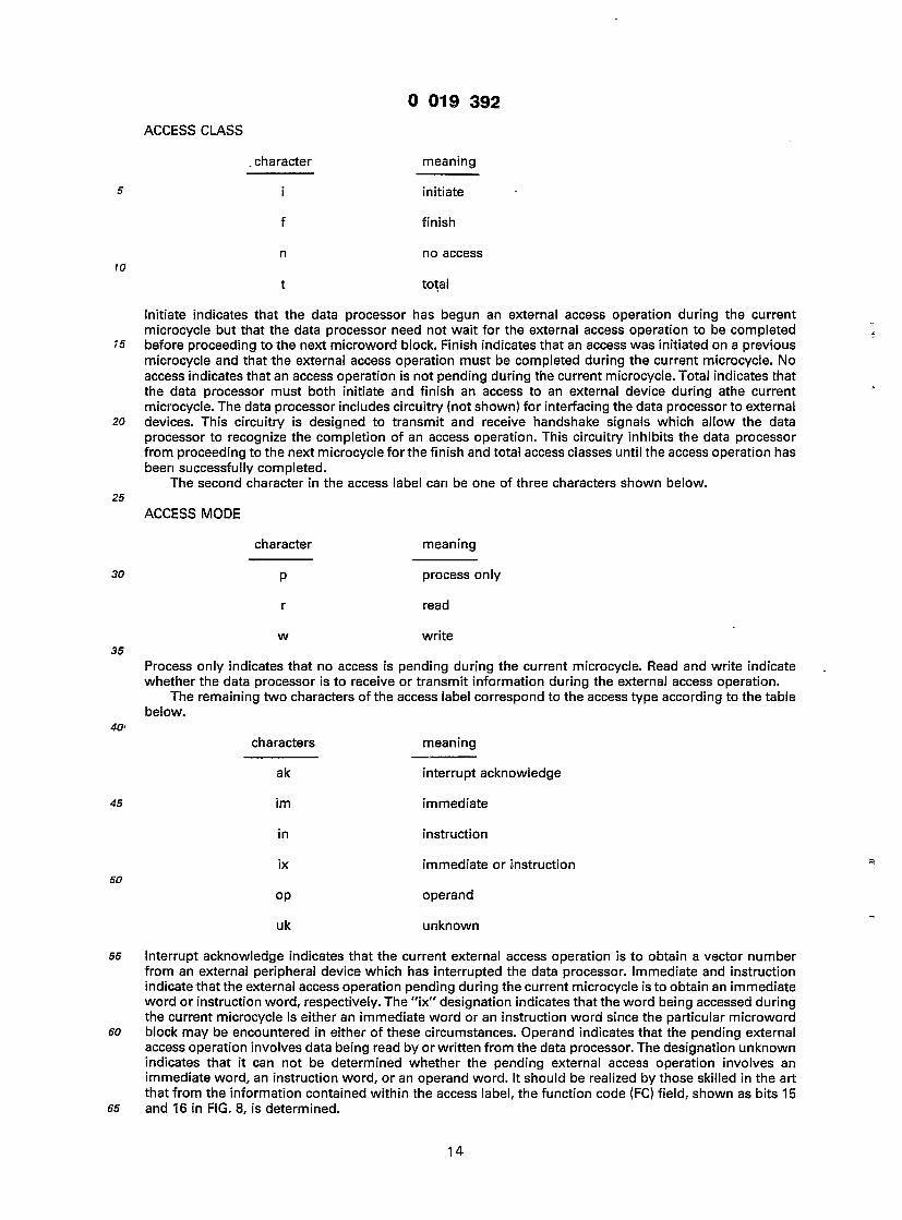
The portion of the key block labeled ACCESS LABEL is used to convey information about the access class, access mode, and access type for each microword block. The first character in the access label can be one of four types as explained in the table below.
13
0 019 3 9 2
ACCESS CLASS
. character meaning
initiate
finish
no access
total
Initiate indicates that the data processor has begun an external access operation during the current microcycle but that the data processor need not wait for the external access operation to be completed before proceeding to the next microword block. Finish indicates that an access was initiated on a previous microcycle and that the external access operation must be completed during the current microcycle. No access indicates that an access operation is not pending during the current microcycle. Total indicates that the data processor must both initiate and finish an access to an external device during athe current microcycle. The data processor includes circuitry (not shown) for interfacing the data processor to external devices. This circuitry is designed to transmit and receive handshake signals which allow the data processor to recognize the completion of an access operation. This circuitry inhibits the data processor from proceeding to the next microcycle for the finish and total access classes until the access operation has been successfully completed.
The second character in the access label can be one of three characters shown below.
ACCESS MODE
character
P
r
meaning
process only
read
w write
Process only indicates that no access is pending during the current microcycle. Read and write indicate whether the data processor is to receive or transmit information during the external access operation.
The remaining two characters of the access label correspond to the access type according to the table below.
characters meaning
ak interrupt acknowledge
im immediate
in instruction
ix immediate or instruction
op operand
uk unknown
Interrupt acknowledge indicates that the current external access operation is to obtain a vector number from an external peripheral device which has interrupted the data processor. Immediate and instruction indicate that the external access operation pending during the current microcycle is to obtain an immediate word or instruction word, respectively. The "ix" designation indicates that the word being accessed during the current microcycle is either an immediate word or an instruction word since the particular microword block may be encountered in either of these circumstances. Operand indicates that the pending external access operation involves data being read by or written from the data processor. The designation unknown indicates that it can not be determined whether the pending external access operation involves an immediate word, an instruction word, or an operand word. It should be realized by those skilled in the art that from the information contained within the access label, the function code (FC) field, shown as bits 15 and 16 in FIG. 8, is determined.
14

D 019 3 9 2
The portion of the key block in FIG. 12 labeled REGISTER POINTERS is a 4-character key which specifies the destination and source registers in the execution unit which are enabled during the current microcycle. The first two characters are one of the six possibilities listed below.
5 DESTINATION REGISTER DECODE
characters meaning
dt data temporary register
dx don't care
rx Rx field in macroinstruction
sp user or supervisor stack pointer
uk unknown
us user stack pointer 20
Similarly, the third and fourth characters in the REGISTER POINTERS key designate the source register which can be one of the six possibilities listed below.
SOURCE REGISTER DECODE 25
characters meaning
dt data temporary register
dy don't care
pc program counter
ry Ry field in macroinstruction
py program counter or Ry fieJd
uk unknown
40 The significance of the portion of the key block in FIG. 12 labeled ALU FUNCTION will be explained hereinafter. The largest portion of the key block is labeled NANOWORD CONTENT which indicates the transfers of information which are enabled within the execution unit during each microcycle. For those microword blocks in which the microword label is not the same as the origin, the execution unit transfer enabled by the nanoword will be the same as those listed for the microword block which is deemed to be
45 the origin. The abbreviations used within the nanoword content portion of each microword block are explained in Appendix B which follows the detailed description.
FIG. 13A— 13CN illustrate the operations performed by each of the microwords. Each of the microword blocks is interpreted according to the key block shown in FIG. 12.
Use of temporary storage and routine sharing are the two basic techniques used to facilitate 50 microroutine minimization. Temporary storage can be used to advantage if operands and addresses are
moved into temporary locations early in the instruction microroutine. This makes later control words in the routine more homogenous and often permits routines to join, which can save considerable space in the control store. Routine sharing is facilitated by the following:
1. Incomplete translation of macroinstruction words by the control store allows extracted fields in the 55 macroinstruction words to specify ALU functions and register selection. Instructions for various functions
which require similar computational operations share the same microroutine. 2. During execution of immediate type macroinstructions, the immediate value is fetched and placed in
a data temporary register, thereby allowing microinstructions involving immediate values to share the register-to-memory and register-to-register microroutines already available.
so 3. The functional branching concept already described allows the various addressing modes to be shared by most single and dual operand macroinstructions which require an operand not already contained within the data processor.
The general micro and nano control store concept allows different microroutine sequences (made up of relatively short control words) to share many of the same nano control words (which are much wider).
65 Each macroinstruction received by the instruction register is emulated by a sequence of microwords. Only
15
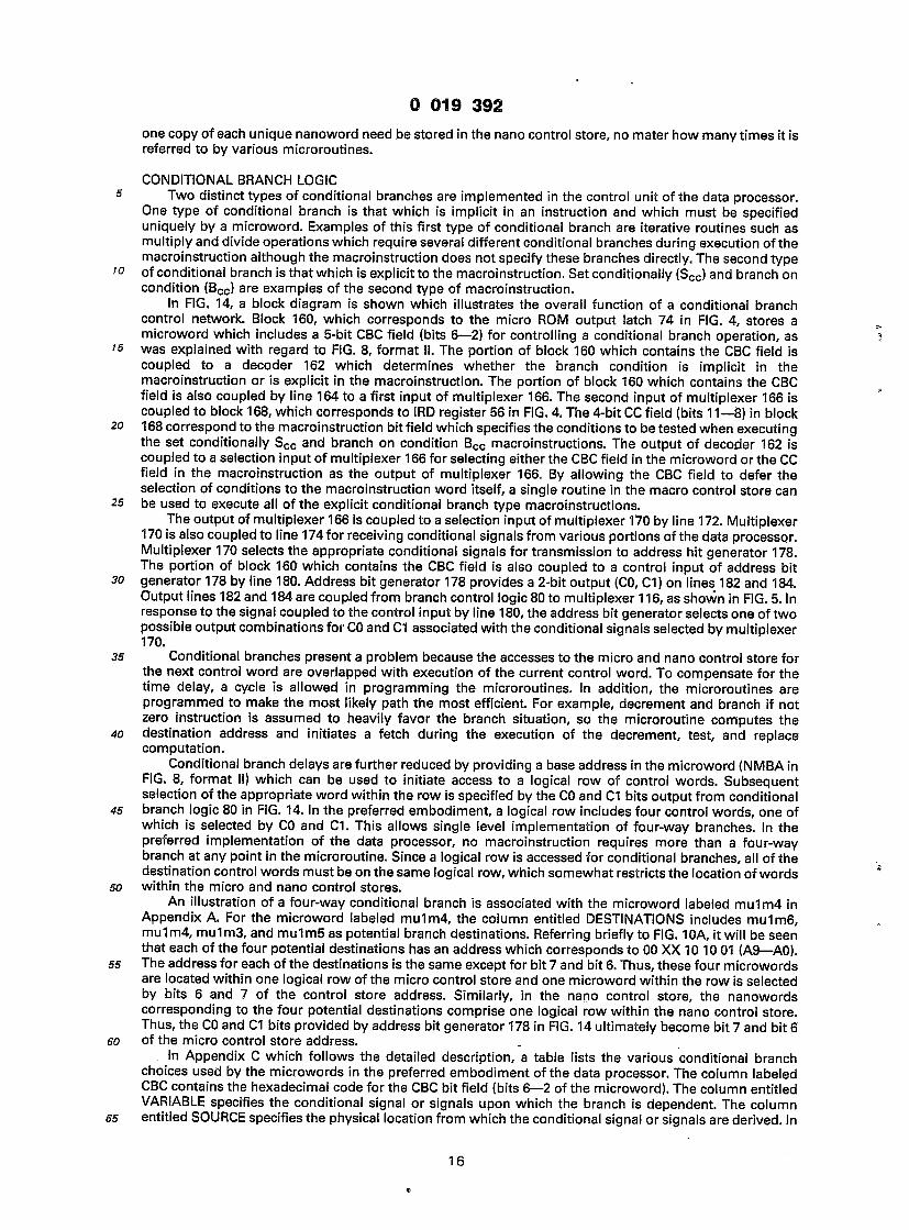
0 019 3 9 2
one copy of each unique nanoword need be stored in the nano control store, no mater how many times it is referred to by various microroutines.
CONDITIONAL BRANCH LOGIC 5 Two distinct types of conditional branches are implemented in the control unit of the data processor.
One type of conditional branch is that which is implicit in an instruction and which must be specified uniquely by a microword. Examples of this first type of conditional branch are iterative routines such as multiply and divide operations which require several different conditional branches during execution of the macroinstruction although the macroinstruction does not specify these branches directly. The second type
10 of conditional branch is that which is explicit to the macroinstruction. Set conditionally (Scc) and branch on condition (Bcc) are examples of the second type of macroinstruction.
In FIG. 14, a block diagram is shown which illustrates the overall function of a conditional branch control network. Block 160, which corresponds to the micro ROM output latch 74 in FIG. 4, stores a microword which includes a 5-bit CBC field (bits 6—2) for controlling a conditional branch operation, as
'5 was explained with regard to FIG. 8, format II. The portion of block 160 which contains the CBC field is coupled to a decoder 162 which determines whether the branch condition is implicit in the macroinstruction or is explicit in the macroinstruction. The portion of block 160 which contains the CBC field is also coupled by line 164 to a first input of multiplexer 166. The second input of multiplexer 166 is coupled to block 168, which corresponds to IRD register 56 in FIG. 4. The 4-bit CC field (bits 1 1—8) in block
20 168 correspond to the macroinstruction bit field which specifies the conditions to be tested when executing the set conditionally Scc and branch on condition Bcc macroinstructions. The output of decoder 162 is coupled to a selection input of multiplexer 1 66 for selecting either the CBC field in the microword or the CC field in the macroinstruction as the output of multiplexer 166. By allowing the CBC field to defer the selection of conditions to the macroinstruction word itself, a single routine in the macro control store can
25 be used to execute all of the explicit conditional branch type macroinstructions. The output of multiplexer 166 is coupled to a selection input of multiplexer 170 by line 172. Multiplexer
170 is also coupled to line 174 for receiving conditional signals from various portions of the data processor. Multiplexer 170 selects the appropriate conditional signals for transmission to address hit generator 178. The portion of block 160 which contains the CBC field is also coupled to a control input of address bit
30 generator 178 by line 180. Address bit generator 178 provides a 2-bit output (CO, C1) on lines 182 and 184. Output lines 182 and 184 are coupled from branch control logic 80 to multiplexer 1 16, as shown in FIG. 5. In response to the signal coupled to the control input by line 180, the address bit generator selects one of two possible output combinations for CO and CI associated with the conditional signals selected by multiplexer 170.
35 Conditional branches present a problem because the accesses to the micro and nano control store for the next control word are overlapped with execution of the current control word. To compensate for the time delay, a cycle is allowed in programming the microroutines. In addition, the microroutines are programmed to make the most likely path the most efficient. For example, decrement and branch if not zero instruction is assumed to heavily favor the branch situation, so the microroutine computes the
40 destination address and initiates a fetch during the execution of the decrement, test, and replace computation.
Conditional branch delays are further reduced by providing a base address in the microword (NMBA in FIG. 8, format II) which can be used to initiate access to a logical row of control words. Subsequent selection of the appropriate word within the row is specified by the CO and C1 bits output from conditional
45 branch logic 80 in FIG. 14. In the preferred embodiment, a logical row includes four control words, one of which is selected by CO and C1. This allows single level implementation of four-way branches. In the preferred implementation of the data processor, no macroinstruction requires more than a four-way branch at any point in the microroutine. Since a logical row is accessed for conditional branches, all of the destination control words must be on the same logical row, which somewhat restricts the location of words
so within the micro and nano control stores. An illustration of a four-way conditional branch is associated with the microword labeled mu1m4 in
Appendix A. For the microword labeled mu1m4, the column entitled DESTINATIONS includes mu1m6, mu1m4, mu1m3, and mu1m5 as potential branch destinations. Referring briefly to FIG. 10A, it will be seen that each of the four potential destinations has an address which corresponds to 00 XX 1 0 1 0 01 (A9— AO).
55 The address for each of the destinations is the same except for bit 7 and bit 6. Thus, these four microwords are located within one logical row of the micro control store and one microword within the row is selected by bits 6 and 7 of the control store address. Similarly, in the nano control store, the nanowords corresponding to the four potential destinations comprise one logical row within the nano control store. Thus, the CO and C1 bits provided by address bit generator 178 in FIG. 14 ultimately become bit 7 and bit 6
so of the micro control store address. In Appendix C which follows the detailed description, a table lists the various conditional branch
choices used by the microwords in the preferred embodiment of the data processor. The column labeled CBC contains the hexadecimal code for the CBC bit field (bits 6—2 of the microword). The column entitled VARIABLE specifies the conditional signal or signals upon which the branch is dependent. The column
55 entitled SOURCE specifies the physical location from which the conditional signal or signals are derived. In
16

) 019 3 9 2
Appendix D, the abbreviations used in the VARIABLE and SOURCE columns are turtner expiamea. i ne column entitled VALUES shows the possible logical states of the variables upon which the branch is conditioned. The columns entitled C1 and CO show the logical values output on conductors 184 and 182 (see FIG. 14) for each of the values or combination of values. In the column entitled REMARKS, information
5 is given for those variables which are comprised of more than one basic conditional signal. In these instances, the order in which the basic conditional signals are listed in the REMARKS column corresponds to the order in which the bits are arranged in the VALUES column. For example, the variable nzl is a combination of the basic conditional signals n and z such that C1 equals "0" and CO equalt "1" when n equals "1" and z equals "0".
<o In Appendix E a table of variables is listed which corresponds to the various branch tests which can be specified by bits 1 1—8 of the conditional branch (Bcc) and set conditionally (Scc) macroinstructions. The cc column gives the hexadecimal equivalent of the four-bit field in the macroinstruction. The "abbreviation" and "meaning" columns specify the desired branch condition while the column entitled CONDITION indicates the logical combination of basic condition code signals required to implement the desired branch
<5 condition. In FIGS. 15A— 15B, a circuit drawing is shown which implements the branch control logic within
dashed block 80 of FIG. 14. Bits 2—6 of the microword (CBC FIELD) are received by conductors 190, 192, 194, 196 and 198. Conductors 190, 192, 194, 196 and 198 are coupled to inverters 200, 202, 204, 206 and 208 for providing the complement of each of the bits in the CBC field on conductors 210, 212, 214, 216 and 218.
20 Conductors 190—196 and complement conductors 210—216, corresponding to the four lesser significant bits of the CBC field, are decoded in a PLA structure similarto the one described in FIG. 9. These conductors are intersected by conductors which have been generally designated CBC decode lines which are labeled at the left-most portion of FIG. 15A. The label associated with each CBC decode line is the hexadecimal equivalent of the CBC bit field which enables that particular decode line. Some of the decode lines are
25 labeled with two numbers such as "1 , 1 1 " indicating that the decode line is enabled regardless of the logic state of bit 6 in the CBC field. In other instances, two or more of the decode lines may have the same label, indicating that all such decode lines may be enabled simultaneously.
Also intersecting the CBC decode lines are a plurality of conductors designated generally CONDITIONALS, including IRD8, IRD8 and END through IRD6. The conditional signals conducted by these
30 lines are provided by various portions of the data processor as explained in Appendix D. The intersection of the conditionals conductors with the CBC decode lines allows the logic state of the one or more decode lines selected by CBC bits 2—5 to be determined by the conditional signals.
Also intersecting the CBC decode line are conductors 220, 222, 224 and 226. Each of these conductors will be pulled to ground level if any of the CRC decode lines with which it intersects (where an intersection
35 is designated by a bubble) is at a high level. Conductor 220 is coupled to output terminal C1 by MOSFET 228 which is enabled when CBC bit 6 is a logic "1". Similarly, conductor 226 is coupled to output terminal C1 by MOSFET 230 which has its gate coupled to the output of inverter 208 and is enabled when CBC bit 6 is a logic "0". Conductors 222 and 224 are coupled to output terminal CO by MOSFETS 232 and 234, respectively, which have the gate terminals coupled to conductors 218 and 198, respectively. MOSFET 232
40 is enabled when CBC bit 6 is a logic "0", and MOSFET 234 is enabled when CBC bit 6 is a logic "1 ". The logic values output on terminals C1 and CO correspond to those listed in Appendix C.
The CBC decode line labeled "9, 19" in FIG. 15A corresponds to the rows labeled 9 and 19 in Appendix C where the conditional branch is determined by the cc field of the macroinstruction. CBC decode line "9, 19" is coupled to the gate terminals of MOSFETS 236 and 238 which are enabled whenever CBC decode line
45 "9, 19" is enabled. MOSFETS 236 and 238 couple conductors 224 and 226 to conductors 240 and 242, respectively. Conductors 240 and 242 are intersected by conductors designated generally cc decode lines in FIG. 150. The cc decode lines are intersected by a group of lines designated generally CC BIT FIELD which conduct signals provided by bit 11 through bit C of the IRD register and signals which are the complement of these bits. These bits of the IRD register correspond to the cc field in Bcc and Scc macroinstructions. The,
so lines designated CC BIT FIELD and the lines previously designated CONDITIONALS overlap in that the IRD8 and IRD8 lines serve as conditional signals for the CBC decode lines. The cc decode lines are intersected by a subset (PSWZ, PSWN, PSWV, PSWC and their complements) of the conditionals conductors which intersected the CBC decode lines. Each of the cc decode lines is labeled at the left-most portion of FIG. 15B such that the labels are the hexadecimal equivalent of the 4-bit cc field which selects that particular cc
55 decode line. A cc decode line is at a high level only if it is selected by the cc bit field and the logic expression in Appendix E for the associated cc field is true. When a cc decode line is at a high level, conductors 240 and 242 are pulled to ground such that conductors 224 and 226 are also grounded provided that CBC decode line 9, 19 is enabled.
Thus the conditional branch choice specified by output terminals C1 and CO may be determined by the 60 CBC field in the microword or directly by the cc field in the macroinstruction. Also, by deferring the final
selection of the C1 and CO output signals to CBC bit 6, the structure allows two different conditional branch microinstructions to share a single common destination. An example of this latter feature is illustrated by the microword blocks labeled bbcil and bbcwl in FIG. 13BM. The branch destination for both of these microword blocks is microword block bbci3 if the condition specified by the cc field is TRUE. However, the
65 branch destination from bbcil is bbci2 if the condition is FALSE while the branch destination from bbcwl is
17

0 019 3 9 2
bbcw3 if the condition is FALSE. In the example, the CBC field of one of the microwords bbcil and bbcwl would be 9 (hex) while the CBC field of the other microword would 19 (hex). Thus, bits 2 through 5 of the CBC field select a condition to be tested while bit 6 of the CBC field selects one of a set of possible output states associated with the selected condition for transmission to the C1 and CO output terminals.
5 ALU AND CONDITION CODE CONTROL UNIT
FIG. 16 is a block diagram of an ALU and condition code control unit which may be used with a microprogrammed data processor. IRD register 56' corresponds to IRD register 56 in FIG. 4 and stores a macroinstruction. Row decoder 241 is coupled to the output of IRD register 55', and the output of row
'0 decoder 241 is coupled to ALU and condition code control block 243 by 15 row selection lines. Row decoder 241 is responsive to the macroinstruction stored by IRD register 56' in order to enable one of the 15 row selection lines. ALU and condition code control block 243 is arranged as a matrix of 15 rows and 5 columns, and row decoder 241 selects one of the 15 rows within block 243.
Nano ROM 73' corresponds to nano ROM 73 shown in FIG. 4. Three bits of the output of nano ROM 73' '5 are coupled to column decoder 244. The output of column decoder 244 is coupled to ALU and condition
control blocks 243 by five column selection lines which select one of the five columns within the row selected by row decoder 241 .
Generally, macroinstructions are executed by performing a sequence of operations in the execution unit. The particular set of operations required to perform a macroinstruction is macroinstruction-static, that
20 is, it the mains fixed during the execution of the macroinstruction and is specified by decoding the instruction type from the IRD register 56'. The set of operations to be performed by the ALU for any particular macroinstruction is stored within one of the 15 rows within block 243. Each operation in the row defines both the ALU activity and the loading of the condition codes. Nano Rom 73' provides state information for the proper sequencing of the operations within the selected row. During each microcycle,
25 column decoder 244 selects the column within the selected row which contains the operation next to be performed in the sequence of operations. Thus ALU and condition code control block 243 combines the state information of the nano control store with the function information extracted from the instruction register in order to execute each macroinstruction. Block 243 provides timing and control to the ALU, ALU extender (ALUE) and to the condition code registers within the program status word (PSW). If the sets of
30 operations for the various macroinstructions are properly ordered in the array contained by block 243, then the execution of most classes of mcroinstruction can utilize the same nano control store sequences. For the same effective address and data types, the ADD, SUBTRACT, AND, OR, and EXCLUSIVE OR macroinstruc- tions share the identical control store sequences.
Still referring to FIG. 16 ALU and condition code control block 243 has a first set of output lines 35 designated 246 which are coupled to the ALU and ALUE within the execution unit (not shown). Control
block 243 also provides a second group of output lines designated 248 which are coupled to a multiplexer 250. Multiplexer 250 includes a first group of inputs which are coupld by lines 252 to the output of condition code core latches 254. The input to the condition code core latches 254 is coupled to logic within the ALU (not shown) which derives status information about the operation most recently performed by the ALU.
40 The status information latched by the condition core latches 254 is selectively coupled to program status word register 86' by multiplexer 250 under the control of the signals provided by lines 248. PSW register 86' corresponds to PSW register 86 in FIG. 4. PSW register 86' also has an input coupled to l/F line 256 which is coupled to nano ROi-1 73' for determining when PSW register 86' is updated. Multiplexer 250 also includes second and third inputs which are coupled by lines 258 and 260 to the Z and C outputs of PSW register 86'.
45 Briefly described, the purpose for conductor 258 is to allow the data processer to test for a zero result in a 32-bit (double word) operation by combining the zero result for the first 16 bits with the zero result of the second 16 bits. The purpose for conductor 260 is to allow the data processor to provide a carry during decimal arithmetic.
FIG. 17 is a table of all the operations which can be performed by the ALU in conjunction with the ALU 50 extender (ALUE). The column entitled "ALU Function" lists the function performed by each operation and,
in the case of shift operations, the pattern in which the bits are shifted. In the "ALU Function" column, the symbols "a" and "d" refer to the input ports of the ALU coupled to the address bus and data bus respectively, within the data section of the execution unit. The symbol "r" refers to the ALU result. The symbol "x" refers to an arithmetic carry (PSWX) rather than the standard carry (PSWC). A symbol which
55 has a primed notation indicates that the complement of the indicated symbol is selected. The column entitled "Into C Bit" indicates the source of the carry output signal. The symbol "cm" refers to the carry generated from the most significant position of the ALU. The symbol "msb" refers to the most significant bit of the result. For shift right and rotate right functions, the source of the carry output signal is bit 0 of the address bus in the DATA section since this bit is coupled to the least significant input of the shift network
60 for such function. The remainder of the columns in FIG. 17 correspond to logic signals which are generated • by the ALU and condition code control unit in order to control the ALU to perform the. desired function.
In FIG. 18, an ALU function and condition code table is illustrated which corresponds to the array of 15 rows and 5 columns already described with regard to ALU and condition code control block 243 in FIG. 16. In the right most column of this- table, all of the macroinstructions which require an ALU function or which
65 affect the state of the condition codes are listed adjacent to the row which contains the set of operations
18

10
25
0 019 3 9 2
required by the particular macroinstruction. Within each of the five columns in the table, the left most entry specifies one of the operations found in the table in FIG. 17. The right most entry contains selection signals for controlling the condition codes stored by the PSW register. The condition code control information is a five character code corresponding to the X, N, Z, V, and C condition code bits in the PSW register. The significance of these condition codes is explained below.
Abbreviation Meaning
X Extend bit used for multiprecision arithmetic w
N Positive/negative: most significant bit of result
Z Zero result
is V Overflow
C Carry
The key for understanding the meaning of the condition code control information listed in the table is 20 shown below:
Abbreviation Meaning
K Condition code not changed 25
D Don't care
0 Condition code always reset
30 N Update PSWN with latest N status
Z Update PSWZ with latest Z status
V Update PSWV with latest V status 35
C Update PSWC with latest C status
C Update PSWC with complement of latest C status
40 C* Update PSWC with PSWC "OR"ed with carry generated during decimal correction.
C* Update PSWC with complement of the above.
45 A Update PSWX, PSWC with arithmetic shift carry status
V Update PSWV with latest status of N exclusive-OR C; used for arithmetic shift left.
so If the condition code control field is left blank in the table, then the condition codes are not affected. In column 1, the condition code control information for rows 2—5 and 8 — 11 include two entries. The reason for having two entries is that the first entry is selected by the nano ROM in some cases while the second entry is selected by the nano ROM in other cases. The nano control word output from the nano ROM includes a 2-bit field (NCCO, NCC1) corresponding to an initiate bit and a finish bit. For columns 2 — 4, the
55 same condition code control information is used if either of the initiate or finish bits is set. For column 1 of the table the first entry is selected when only the initiate bit is set. However, where only the finish bit is set, then the second entry for the condition code control information is used.
Referring briefly to FIG. 12, the description of the portion of the key block labeled "ALU FUNCTION" has been deferred until now. One, two, or three characters may appear in the ALU function portion of the
60 microword block in FIGS. 13A— 13CN. For each of the microword blocks, the first character indicates the column of the table shown in FIG. 1 8 which is to be selected in order to perform the desired operation. The symbols 1 — 5 correspond to columns 1 through 5 in this table. The symbol "x" indicates a don't care condition. In addition, the symbol 6, which occurs in microword blocks used to perform a divide alghorithm, indicates that column 4 is enabled but that the "1ss" ALU function will shift a logic "1" into the
65 least significant bit of the ALUE instead of a logic "0" as is the case when a "4" appears.
19

0 019 3 9 2
If two or more characters appear in the "ALU function" portion of the microword block, then the second character refers to the finish and initiate identification for condition code control. The symbol "f" corresponds to finish and would therefore cause the second entry in column 1 of the table shown in FIG. 18 to be used in order to control the setting of the condition code bits in the PSW register. The symbol "\"
5 specifies initiate and would select the first entry in column 1 of the table shown in FIG. 18 for controlling the setting of the condition code bits in the PSW register. The symbol "n" indicates that the condition codes are not affected for the particular operation. Finally, for those microword blocks which contain a three character code for the "ALU FUNCTION" portion, the third character is the symbol "f" which indicates to the execution unit that a byte (8 bits) transfer is involved. An example is the microword block labeled
w mrgwl shown in FIG. 13H. In these instances, only the low order 8 bits of the address bus in the DATA section of the execution unit are driven by the selected source such that only the low order 8 bits of the selected destination are changed while the upper 8 bits of the selected destination are not disturbed. Otherwise, word operation and byte operation type macroinstructions share the same basic microinstruction routines.
15 Referring again to FIG. 18, it should be noted that in the "addx" operation in row 3, column 2, the arithmetic carry added to the operands is the core latch copy of X rather than PSWX such that the most- recent X status is used. Also in row 1, column 4, the operation performed is an "1ss" operation wherein the logic state of the bit shifted into the ALUE is determined by whether column 4 or column 6 is selected by the nano control store, though column 6 does not appear as a separate column in the table. Also, in row 7,
20 column 4, the input to the most significant bit of the ALU is PSWC, or PSWN exclusive-or PSWV, depending on whether the multiplication is unsigned or signed, respectively.
In FIG. 19, a table illustrates the decoding of the macroinstruction stored by the IRD register in order to select one of the fifteen rows in the matrix contained by the ALU and condition code control block. The macroinstructions have been grouped into 45 combinations (0 — 44) as determined by the bit pattern shown
25 in the section of the table.entitled Instruction Decode. In the portion of the table entitled "Row Inhibits", the numbers which appear in a given row of the table correspond to the rows in the ALU and condition code control matrix which are to be disabled whenever a microinstruction is encountered which has the bit pattern shown in the corresponding row of the instruction decode portion of the table.
In FIGS. 20A — 20B, a programmed logic array structure is illustrated for performing the decoding 30 function described in the table of FIG. 19. In FIG. 20A, a group of lines designated IRD REGISTER OUTPUTS
AND COMPLEMENTS is illustrated. EAch of these lines conducts the true or complement signal of a macroinstruction bit stored in the IRD register. Intersecting this first group of lines is a second group of lines designated generally MACROINSTRUCTION DECODE LINES which continue from FIG. 20A onto FIG. 20B. The macroinstruction decode lines are labeled with a reference numeral which corresponds to a row in
35 the table of FIG. 19. At the intersection of a line in the first group with a line in the second group (the intersection being represented by a bubble), a MOSFET device pulls the line in the second group to ground whenever a line in the first group is a logic "1". In some cases, one of the macroinstruction decode lines intersects another of the macroinstruction decode lines. For example, macroinstruction decode line 43 is shown intersecting with macroinstruction decode line 44. At this intersection, a MOSFET device operates to
0 pull macroinstruction decode line 44 to ground whenever macroinstruction decode line 43 is a logic "1". Similarly, macroinstruction decode lines 41 and 42 also intersect macroinstruction decode line 44. Referring briefly to the table in.FIG. 19, the row numbered 44 is followed by rows set off in parenthesis and labeled 41, 42 and 43. This notation is used to indicate that rows 41, 42 and 43 further deconde row 44.
In FIG. 208, the macroinstruction decode lines are intersected by a third group of lines designated 45 generally ROW SELECTION LINES and labeled 1 through 15. The row selection lines correspond to the 15
lines coupled to the output of row decoder 241 in FIG. 16. The decoding function performed by the PLA structure shown in FIG. 20B is effective to select one of the 15 rows in the ALU and condition code control matrix based on the information supplied by the macroinstruction decode lines.
FIG. 21 A and 21 B illustrate the Gircuit implementation of ALU and condition code control block 243 in so FIG. 16. A first group of lines designated ROW SELECTION LINES is illustrated in the upper portion of FIG.
21 A and FIG. 21 B. This group of row selection lines corresponds to the 15 row selection lines output by the PLA structure shown in FIG. 20D. The row selection lines are intersected by a first group of lines designated ALU CONTROL DECODE LINES in FIG. 21 B in order to control the signals which select the ALU function. Shown in FIG. 21 B are conductors 262, 264, and 266 which receive a 3-bit field provided by the output of the
55 nano ROM. Inverters 268, 270, and 272 are coupled to conductors 262, 264, and 266, respectively, for providing the complement signals on lines 274, 276, and 278. Lines 262, 264, 266, 274, 276 and 278 are intersected by lines designated COLUMN SELECT LINES and labeled 1, 2, 3, 4+6, 5 in order to decode the 3- bit field supplied from the nano ROM. The five lines designated column select lines correspond to the five lines coupled to the output of column decoder 244 in FIG. 16. Column selection line 2 is coupled to a load
so device 280 for holding column selection line 2 at a high level whenever column selection line 2 is enabled. Column selection line 2 is also coupled to a buffer device 282, and the output of buffer 282 is coupled to line 284 labeled ICS2. The other column selection lines are similarly buffered in order to drive lines ICS1, ICS3, ICS4, and ICS5.
Line 286 in FIG. 21 B provides ALU control signal CAND. Referring briefly to FIG. 17, one of the columns 65 in the table is labeled cand' and the table illustrates those operations for which the signal is active. Signal
20
I 019 3 9 2
<o
\5
25
CAND is active low and the intersection of line 286 with line ICS1 causes l anu to oe active wnenever column 1 is selected. In FIG. 18, it will be noted that column 1 always calls for an "and" function to be performed by the ALU, and from the table in FIG. 17 it will be seen that the "and" function is one of those operations for which signal cand' is to be active. If column 2 is selected rather than column 1,then line 284
5 is at a high level and MOSFET 288 is enabled such that line 286 is coupled to decode line 290. In this case, line 290 is grounded such that signal CAND is active only when the row 4 selection line is enabled. Referring briefly to FIG. 18, it will be seen that within column 2 of the table, row 4 contains the only operation ("and") which requires cand' to be active. On the other hand, if column 4+6 is selected, then MOSFET 292 is enabled such that line 286 is shorted to decode line 294. Line 294 is grounded for making
0 signal CAND active whenever row selection lines 2, 5, 7, 8 or 10 are selected. Again referring to FIG. 18, it will be noted that the corresponding rows in column 4 of the table call for operations for which signal cand' is to be active. The remainder of the control signals which control the ALU are generated in a similar manner.
The row selection lines are also intersected by a second group of lines designated CONDITION CODE 5 CONTROL DECODE LINES in FIG. 21 A in order to generate the control signals which determine the setting
of the condition code bits. The buffered column selection line ICS1— ICS5 in FIG. 21 A determine which of the condition code control decode lines is coupled to the various control signals. For example, when line 284 (ICS2) is at a high level, MOSFET 296 couples decode line 298 to INX control line 300 for controlling the setting of the X bit in the program status word register (PSWX). In this example, INX control line 300 will be
10 disabled whenever row selection lines 1, 4, 6, 7, 8, 11, 13, or 14 are selected. Referring briefly to the table in FIG. 18 for column 2, it will be noted that for the rows mentioned above, the symbol "k" appears for the X bit position indicating that the PSWX bit should not be changed.
Also shown in FIG. 21A are conductors 302 and 304 which receive control signals NCC0 and NCC1 which are 2 bits provided by the output of the nano control store and correspond to the initiate and finish
15 signals previously referred to in the description of the table in FIG. 18. Conductors 302 and 304 are coupled to the input of inverters 306 and 308, respectively, for generating the signals INIT and FINISH on lines 310 and 312, respectively. Line 310 intersects decode line 314 and line 312 intersects decode line 316 such that decode line 314 is enabled when INIT is a logic "0" and decode line 316 is enabled when FINISH is a logic "0". MOSFET devices 318 and 320 couple decode lines 314 and 316 to control lines 322 and 324,
30 respectively, and are enabled when line 326 (ICS1) is at a high level indicating that column 1 has been selected. Control lines 322 (INVI) and 324 (INVF) are gated by circuitry (not shown) in order to control the setting of the overflow bit in the program status word register (PSWV). Decode line 314 is grounded whenever rows 13 or 14 are selected while decode line 316 is grounded whenever rows 2—5 or 8—1 1 are selected. Referring briefly to the table in FIG. 18 in column 1, it will be noted that for an initiate type
35 operation, the V bit in the program status word register is unchanged only in rows 13 and 14 while for the finish type operation, the V bit in the program status word register is unchanged in rows 2—5 and 8—11.
Lines 302, 304, 310, 312 are also coupled to a gating network which includes AND gates 323 and 330 and NOR gate 332 for generating a gated signal on line 334. If the signals received by conductors 302 and 304 are both logic "0", then line 334 is enabled and causes the condition code control signals to be disabled
40 such that the condition codes in the program status word register are unchanged. This case corresponds to those microword blocks in FIG. 13A— 13CN for which the ALU function portion indicates that the condition codes are not affected. Conductor 336 (INHCC) also intersects the condition code control lines such that these control lines are disabled when line 336 is a logic "1". Line 336 is coupled to a decoder (not shown) which detects those macroinstructions which do not affect the condition codes. In the case of these
45 macroinstructions, line 336 is enabled in order to inhibit the condition codes in the PSW register from being affected.
Referring again briefly to FIG. 21 B, a sixth column select line appears which is labeled 0 and which is coupled to the input of buffer 337 for driving conductor 338 (ALURL). The significance of this signal will now be explained. Whenever at least one of the nano control store output bits (NIFO— NIF2) received by
50 conductors 262, 264 and 266 is a logic "1" then one of the column select lines 1—5 is enabled indicating that the ALU is to perform an operation. In this event, a temporary storage register or latch within the ALU is updated. However, during certain microcycles, no ALU function is to be performed and the latch within the ALU should not be updated. For these microcycles, conductors 262, 264 and 266 receive logic "0" signals such that column select line 0 is enabled. The (ALURL signal conducted by line 338 signifies this
55 case and inhibits activity within the ALU latch.
35
45
50
so
65
21

0 019 3 9 2
APPENDIX A
LIST OF MICROWORDS
KUUXINh LiABEli FC NMA TYPE
o#w1 o#w1 i a2
ablwl ablwl i ablw2 db
ablw2 i ablw3 db
ablw3 d a3
abwwl abwwl i ablw3 db
adrwl adrwl d adrw2 db
adrw2 u a3
adswl adswl i adsw2 db
adsw2 u adrw2 db
e#w1 e#w1 i a2
aixwO aixwO n aixwl db
aixwl i b e
aixw2 i adsw2 bd
aixw4 i adsw2 db
pinwl pinwl d pinw2 db
pinw2 d a3
pdcwl pdcwl n pdcw2 db
pdcw2 d a3
o#H o#H i o#w1 db
a b l l l a b l l i i a b l l 2 db
ab l l2 i a b l l 3 db
ab l l3 d ad r l2 db
abwll abwll i a b l l 3 db
a d r l l a d r l l d ad r l2 db
adr l2 d a3
a d s l l ads l l i ads l2 db
ads 12 u ads 13 db
adsl3 u a3
e#H e#H i e#w1 db
aixlO aixlO n a i x l l db
a ix l 1 i be
i l l aixw2 a ixw4
a i a i l
a i a i l
ab lwl
ablw2
abwwl
adswl
a b l l 3
aixwO
111 a ixwl a ix!2 a i x l S
!2
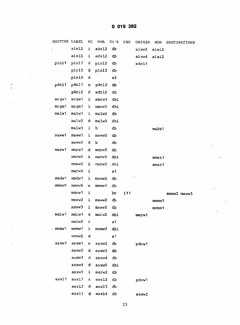
0 019 3 9 2
KOUT!N£ .LABEL FC NMA Tl VE
a ix l2 i adsl2 db
a ix lS i adsl2 db
p i n l l p i n l l d p in l2 db
p in l2 d p in l3 db
p in l3 d a3
pdcl l pdc l l n pdcl2 db
pdcl2 d adr l2 db
mrgwl mrgwl i mmrw3 d b i
mrgml mrgml i mmrw3 d b i
malwl malwl i malw2 db
malw2 d nsalw3 d b i
malw3 i b db
mawwl mawwl i maww2 db
maww2 d b db
mmrwl mmrwl d mmrw2 db
ncarw2 i nmrw3 d b i
imaw2 i n=nrw3 . d b i
mmrw3 i a1
mmdwl mmdwl i maww2 db
ntmxwO mmxwO n rrnocwl db
mrocwl i be
ntmxv2 i maww2 db
mmxw3 i maww2 db
ntmiwl mmiwl d rmaiw2 d b i
mniiw2 i a 1
ntmmwl mmmwl i mmmw2 d b i
ncnniw2 d a 1
asxwl asxwl n asxw2 db
asxv2 d asxw3 db
asxw3 d asxw4 db
asxv4 d asxw5 d b i
asxw5 i morw2 db
asx l l a sx l l n asxl2 db
asxl2 d asxl3 db
asxl3 d asx!4 db
ORIGIN ROW DESTINATIONS
aixw2 a i a i 2
aixw4 a i a i 2
a d r l l
mabbi
mmst 1
mmstl
i l l mmxw2 nunxw3
UU1U1UQI
nunmml
mmrwi
pdcwl
pdcwl
asxw2
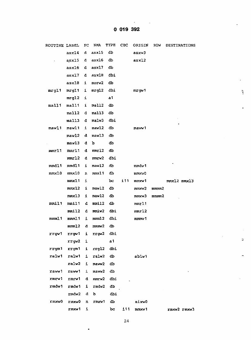
0 019 3 9 2
ROUTINE LABEL FC NMA TYPE
asxl4 d asx!5 db
asx l5 d asxl6 db
asx l6 d asxl7 db
asx l7 d asxl8 d b i
asx l8 i morw2 db
nirgl l mrgl l i mrgl2 d b i
mrgl2 i a1
m a i n m a i n i mall2 db
mall2 d mall3 db
mall3 d malw3 d b i
mawl 1 mawll i mawl2 db
maw 12 d mawl 3 db
mawl 3 d b db
mmrll mmrll d mmrl2 db
mmrl2 d mmrw2 d b i
nundll mmdll i mawl 2 db
mmxlO mmxlO n mmxll db
nunxll i be
mmxl2 i mawl2 db
mmxl3 i mawl2 db
mini 11 iranill d mmil2 db
mmil2 d mmiw2 d b i
mmmll mmml 1 i mmml2 d b i
mmml2 d mmmw2 db
r rgwl rrgwl i rrgw2 d b i
rrgw2 i a1
rrgml rrgml i r rg l2 d b i
r a lwl ra lwl i ralw2 db
ralw2 i maww2 db
rawwl rawwl i maww2 db
rmrwl rmrwl d mmrw2 d b i
rmdwl rmdwl i rmdw2 db
rmdw2 d b d b i
rmxwO rmxwO n rmxwl db
rmxw 1 i be
CBC ORIGIN ROW DESTINATIONS
asxw3
a s x ! 2
mrgwl
mawwl
mmdwl
mmxwO
i11 mmxwl mmxl2 mmxl3
mmxw2 mmmm2
mmxw3 mmmm2
mmrl l
mmrl2
mmmwl
a b l w l
aixwO
111 mmxwl rmxw2 rmxw 3

una 3 9 2
OUTINE LABEL FC NMA Tift- CJB<~ UKJ.L>i.w
rmxw 2 i rmdw2 bd aixw2 3
rmxw 3 i rmdw2 db aixw4 :
rmiwl rmiwl d mmiw2 dbi rmrwl
rmmwl rmmwl i mmmw2 dbi.
r r g l l r r g l l i r r g l 2 dbi r r gwl
r r g l 2 i a1
r a l l l r a i n i r a l l 2 db ab lwl
r a l l 2 i r a l l 3 db r a l w 2
r a l l 3 d mawl3 db
rawll rawl l i r a i l 3 db rawwl
rmr l l rmr l l d rmrl2 db
rmrl2 d rmrl3 d b i
rmrl3 i a l
rmdll rmdll i rmdl2 db rmdwl
rmdl? d rmdl3 db r a l l 3
rmdl3 d rmrl3 dbi rmdw2
rmxlO rmxlO n rmxll db aixwO
rmxll i be i11 mmxwl
rmxl2 i rmdl 2 db aixw2
rmxl3 i rmdl2 db aixw4
rmi l l rmi l l d rmil2 db r m r l l
rmil2 d rmil3 d b i
rmil3 i a1
rmmll rmmll i rmml2 dbi rmmwl
rmml2 d mnunw2 db
morwl raorwl i morw2 d b i
morw2 d a1 maww2
morl l morll i morl2 dbi morwl
nor 12 d morw2 db
romwl romwl i rrgw2 d b i
romml romml i rorm2 dbi romwl
romll romll i roml2 dbi romwl
roml2 i roml3 db
roml3 d a1
rorwl rorwl i rrgw2 d b i

KUUTJ.NE LABEL
r o r l l r o r l l
r o r l 2
r o r l 3
roawl roawl
roaw2
r o a l l r o a l l
r o a l 2
r o a l 3
r o a l 4
rorml ror ra l
rorm2
rorm3
dvur 1 dvur 1
dvur 2
dvur3
dvuml dvuml
dvum2
dvum3
dvum4
dvumz
dvuma
dvum5
dvum6
dvum7
dvum8
dvum9
dvumd
dvumb
dvumc
dvume
dvumf
dvumO
dvsOl dvs01
dvs02 dvs02
dvs03
FC NMA TYPE
i r o r l 2 d b i
i r o r l 3 db
n roml3 db
i roaw2 d b i
i a1
i r oa l2 d b i
i r oa l3 db
n roa l4 db
n a1
i rorm2 d b i
i rorm3 db
n rom!3 db
ri dvum2 db
n dvur 3 db
n t r ap3 db
n dvum2 db
n be
n be
i dvuma d b i
i dvuma d b i
i a1
n be
n be
n be
n be
n dvumd db
i dvumO d b i
n be
n b e
n dvumS db
i dvumO d b i
i a1
n dvs03 db
n dvs03 db
n be
0 019 3 9 2
CBC ORIGIN ROW DESTINATIONS
ro rwl
r o s e !
roawl
ro rwl
r o r ! 2
z dvum3 dvur 2
c t r dv l dvum4 dvum5
dvdvl
dvdvl
dvdvl
n dvdv 1 dvuin8 dvun\7
n dvdv 2 dvum8 dvum7
auz dvdv 3 dvum6 dvum9
auz dvum7 dvdv 3 dvumb dvumc
dvdv2
dvdv 5
c dvdv 4 dvum6 dvuma
c dvum9 dvdv 4 dvumd dvumf
dvdv2
dvdv 5
d v u r l
dvuml
nz1 dvs04 dvs05
16
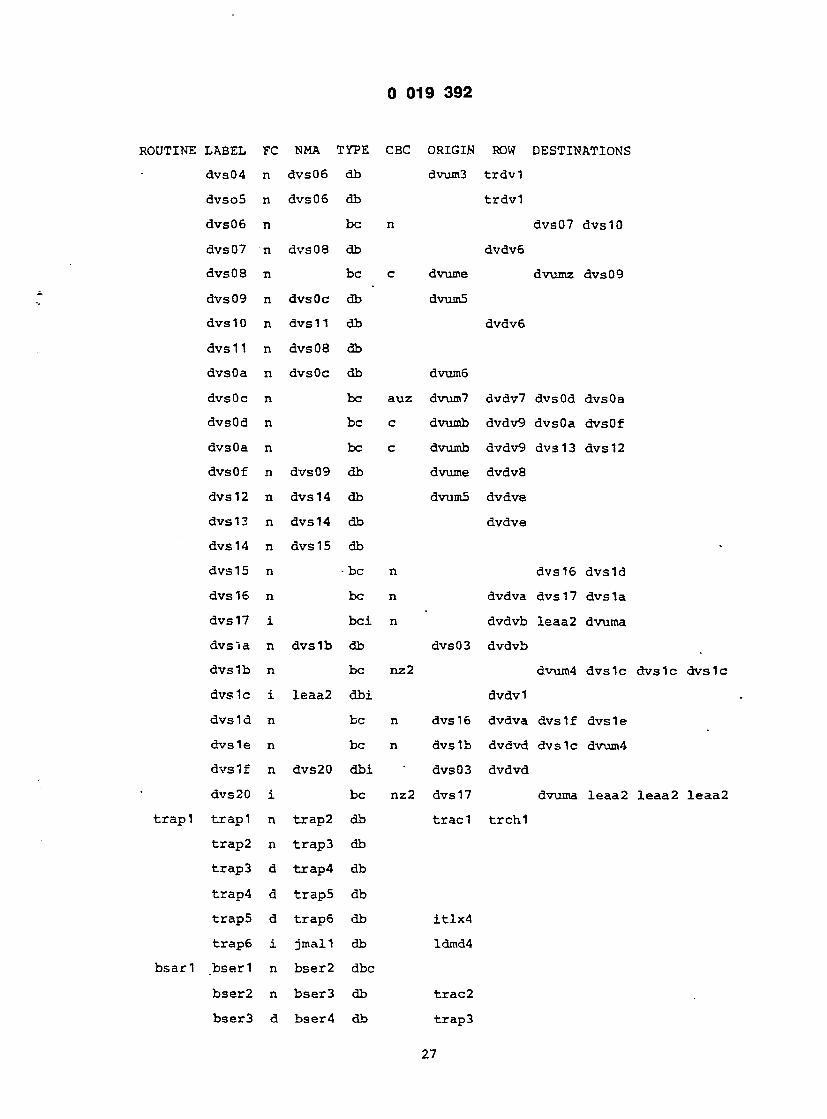
0 019 3 9 2
ROUTINE LABEL
dvs04
dvso5
dvs06
dvs07
d v s 0 8
dvs09
dvs10
dvs11
dvsOa
dvsOc
dvsOd
dvsOa
dvsOf
dvs12
dvs 13
dvs 14
dvs15
dvs 16
dvs 17
dvs "i a
dvs 1b
dvs 1c
d v s l d
dvs 1e
dvs I f
dvs20
t r a p l t r a p l
t r a p 2
t r a p 3
t r a p 4
t r a p 5
t r a p 6
bsa r l b s e r l
b s e r 2
b s e r 3
FC NMA TYPE CBC ORIGIN
n dvs06 db dvum3
n dvs06 db
n be n
n dvs08 db
n be c dvume
n dvsOc db dvum5
n dvs 11 db
n dvs 08 db
n dvsOc db dvum6
n be auz dvum7
n be c dvumb
n be c dvumb
n dvs09 db dvume
n dvs 14 db dvum5
n dvs 14 db
n dvs 15 db
n - be n
n be n
i bci n
n dvs 1b db dvs03
n be nz2
i leaa2 d b i
n be n dvs 16
n be n dvs 1b
n dvs20 dbi dvs03
i be nz2 dvs 17
n t rap2 db t r a d
n t r ap3 db
d t rap4 db
d t rap5 db
d t rap6 db i t l x 4
i jmall db ldmd4
n bser2 dbc
n bser3 db t r a c 2
d bser4 db t r a p 3
ROW DESTINATIONS
t r d v l
t r d v l
dvs07 dvs 10
dvdv6
dvumz dvs09
dvdv6
dvdv7 dvsOd dvsOa
dvdv9 dvsOa dvsOf
dvdv9 dvs 13 dvs 12
dvdv8
dvdve
dvdve
dvs 16 d v s l d
dvdva dvs 17 dvs 1a
dvdvb leaa2 dvuma
dvdvb
dvum4 dvs lc dvs lc dvs 1
dvdvl
dvdva dvs 1 f dvs 1 e
dvdvd dvslc dvum4
dvdvd
dvuma leaa2 l eaa2 l e a a
t r c h l
27

0 019 3 9 2
ROUTINE LABEL FC NMA TYPE CBC ORIGIN
bser4 d bser5 db
bser5 d bser6 db t r a p 3
bser6 d t rap3 db
i t 1x1 i t l x l n i t 1x2 db t r a d
i t 1x2 n i t 1x3 db
i t l x 3 n i t l x 4 db
i t l x 4 d i t l x 5 db
i t l x 5 a i t l x 6 db
i t 1x6 n i t 1x7 dbi dvumb
i t l x 7 n t r ap4 db
t r a d t r a d n t r ac2 db
t r a c 2 n t rap3 db
mpow! mpowl i mpow2 db adswl
mpow2 d mpow3 d b i
mpow3 d b db
mpoll mpolt i mpol2 db adswl
mpol2 d mpol3 d b i
mpol3 d mpow2 db
mpiwl mpiwl i mpiw2 db adswl
mpiw2 d mpiw3 db
mpiw3 d mpiw4 d b i
mpiw4 i a 1
mpi l l mpi l l i mpil2 db adswl
mpil2 d mpil3 db mpiw2
mpil3 d mpil4 db
mpil4 d mpiw3 db
cmmwl cmmwl d cmmw2 db
cmmw2 d cmmw3 db
cmmw3 d cmmw4 d b i
cmmw4 i a 1
cmmll cmrnll d cmml2 db cmmwl
cmml2 d cmml3 db cmmw2
cmml3 d cmml4 db
cmml4 d cmml5 dbi cmmw3
cmml5 d cmml6 db
28

t 019 3 9 2
tOUTINE LABEL FC NMA TYPE CBC ORXCiiN
cmml6 i cmml7 db
cmml7 i a1
exgel exgel i exge2 d b i
exge2 i r ca l3 db
asbbl asbbl n asbb2 db pdcwl
asbb2 d asbb3 db asxw2
asbb3 d asbb4 db asxw3
asbb4 d asbb5 dbi asxw4
asbb5 i asbb6 db
asbb6 i morw2 db
rbrb l rb rb l i rbrb2 dbi r o r w l
rbrb2 i rbrb3 db a sbb6
rbrb3 n a1
b b i mmrw3 d b i
maqwl maqwl i morw2 d b i
maqll maqll i morl2 dbi maqwl
raqwl raqwl i roaw2 d b i
r a q l l r a q l l i roa!2 dbi r aqwl
r l q l l r l q l l i mmrw3 d b i
h a l t l h a l t l d h a l t l db dvumb
s topl s top l n a1
cpmml cpmml i cprm2 dbi romwl
cpdwl cpdwl i mmrw3 d b i
cpdl l cpdl l i cpdl2 dbi cpdwl
cpdl2 i a1
rcawl rcawl i rcaw2 dbi roawl
rcaw2 i a1
r c a l l r c a l l i r ca l2 dbi roawl
r ca l2 i rca l3 db
rca l3 n a1
cpmwl cpmwl i rcaw2 dbi romwl
cpmll cpmlt i cpml2 dbi romwl
cpml2 i r ca l3 db
cprwl cprwl i rcaw2 dbi r o r w l
c p r l l c p r l l i cpr!2 dbi r o r w l
29

0 019 3 9 2
ROUTINE LABEL FC NMA TYPE CBC ORIGIN
cprl2 i r ca l3 db
cprm.1 cprml i _cprm2 dbi r o r w l
cprm2 i r ca l3 db
s t iw l s t iwl n st iw2 db t r a d
stiw2 n s t iw3 db
stiw3 n st iw4 db
stiw4 n malw3 db
r s tw l rs twl n s t iw4 db
mstwl mstwl n s t iw4 db
stmwl stmwl i stmw2 d b i
stmw2 i morw2 db
s t rwl s t rwl i strw2 dbi t r a d
strw2 i r ca l3 db
tsmwl tsmwl i mmrw3 d b i
t s rwl t s rwl i mmrw3 dbi r r gwl
t sml l t smll i tsml2 dbi tsmwl
tsml2 i a1
t s r l l t s r l l i t s r l 2 dbi r r g w l
t s r l 2 i a1
suspl suspl i ex t r2 dbi e x g e l
lu sp l luspl i leaa2 dbi l e a a l
swapl swap2 i swap2 d b i
swap2 i a1
r s e t l r s e t l n r s e t 2 db s t o p l r s e t 2 n r s e t 3 d b i
r s e t 3 a r s e t 4 db
r s e t 4 a . be auz dvumb
r s e t 5 i a1
r s t p l r s t p l n r s t p 2 dbc
r s tp2 n r s tp3 db
r s tp3 i r s t p 4 db
r s tp4 i r s t p 5 db r s t p 3
r s tpS i jmall db
mulrl mulrl i mulm2 d b i
mulml mulml i mulm2 d b i
r s r s l
r s r s !
r s e t 3 r s e t 5
30

0 019 3 9 2
ROUTINE LABEL FC NMA TYPE CBC ORIGIN ROW
mulm2 i be msO r o r l 2
mulm3 n mulm4 db mumul
mulm4 n be m01 mumul
raulmS n mulm4 db mumul
mulm6 n a 1 mumul
rmmwl nnmwl i morw2 d b i
nnrwl rmrwl i roaw2 d b i
nnmll nnmll i rmml2 bdi nnmwl
nnml2 i morw2 db
n n r l l n n r l l i nnrl2 bdi nnrwl
nnr l2 i roa l4 db
nbcr l nbcrl i nbcr2 dbi nn rwl
nbcr2 i nbcr3 db a s b b 6
nbcr3 n a1 n b s r l
nbcml nbcml i asbb6 d b i
e x t r l e x t r l i ext r2 d b i
ex t r2 i a1
j s a l l j s a l l i j s a l 2 db a b l w l
j s a l 2 i jsaw2 db
jsrd-1 j s r d l n j s rd2 db
j s rd2 i j s rd3 db
j s rd3 i jsaw2 db
jsawO jsawO n jsawl db
jsawl i jsaw2 db
jsaw2 d jsaw3 db
jsaw3 d b db i
j s r a l j s r a l i jsaw2 db
jsrxO jsrxO n j s r x l db aixwO
j s r x l n be i 11
j s rx2 n j s rd2 db j s j s -1
j s rx3 n j s rd2 db j s j s l
jmawl jmawl n jmal2 db jsawO
jmpal jmpal i b db
jmall jmall i jmal2 db a b l w l
jmal2 i b db
mulm4 mulm3 mulm4 mulm5
j s rx2 j s r x 3
31

0 019 3 9 2
ROUTINE LABEL FC NMA TYPE CBC ORIGIN ROW DESTINATIONS
jmpdl jmpdl n bbci3 db j s r d l
jmpxO jmpxO n jmpxl db aixwO
jrnpxl n be i l l j s r x l jmpx2 jmpx3
jmpx2 n bbci3 db j s rx2 jmjml
jmpx3 n bbci3 db j s rx3 jmjml
dcn t l dcnt l n dcnt2 db
dcnt2 i bci ze dcnt4 d c n t 3
dent 3 i dent 5 db rcaw2 d e d e !
dcnt4 i b db r o r l 2 d e d d
dcnt5 i mmrw3 db b
b b c i l bbc i l n be cc dcntl mabb! bbci2 b b c i 3
bbci2 n b db r c a ! 3
bbci3 i b db
bbcwl bbcwl n be cc bbcw3 b b c i 3
bbcw3 n malw3 db rea l3 mabb!
l a a l l l a a l l i l a a l2 db o # H
laa l2 i b db o#w1
laaw! laaw! i b db
l e a a l l eaa l i leaa2 d b i
leaa2 i a1 dvdv l
l ead l leadl i lead2 db
lead2 i b db
leaxO leaxO n leax! db aixwO
l e a x f i be i 1 1 aixwl leax2 l e a x 3
leax2 i leax4 db l e l x !
leax3 i leax4 db l e l x l
leax4 n b db
peaxO peaxO n peaxl db aixwO
peaxl i be i11 aixw! peax2 p e a x 3
peax2 i peax4 db aixw2 p e p x l
peax3 i peax4 db aixw4 p e p x l
peax4 n peax5 db
peax5 i peax6 db
peax6 d morw2 db b s r i 2
p a a l ! paa l ! i paa!2 db ab lw!
32

0 019 3 9 2
:OUTINE LABEL FC NMA TYPE CBC ORIGIN
paal2 i paaw2 db
paawl paawl i paaw2 db
paaw2 d maw 13 db b s r i 2
peaa l peaal i peax6 d b i
peadl peadl i pead2 db
pead2 i pead3 d b i
pead3 i peax6 db
b s r i l b s r i l n b s r i2 db
bs r i2 d bs r i3 db
b s r i 3 ^d malw3 db
bsrwl bsrwl n bsrw2 db
bsrw2 d bsrw3 db b s r i 2
bsrw3 d malw3 db
un lk l unlkl d unlk2 db ldmr2
unlk2 d unlk3 dbi ablwl -
unlk3 i unlk4 db
unlk4 i a1
l i n k l l i nk l i l ink2 db
l ink2 i l ink3 db j s r d 3
l ink3 d l ink4 d b i
l ink4 d mmiw2 db
chkr l chkrl i chkr2 db i
chkr2 i be nv
chkr3 n be n dvumb
chkr4 n a1
chkml chkml i chkr2 d b i
r t r l r t r l d r t r 2 db cmmw3
r t r2 d r t r3 db malw3
r t r 3 d r t r 4 db smaw2
r t r 4 d jmal2 db
r t s1 r ts1 d r t s2 db cmmw3
r t s2 d r t s3 db a b l w l
r t s3 i b db
bcsml bcsml i bcsm2 d b i
bcsm2 d a1
ROW DESTINATIONS
t r a p l t r a p l chkr3 t r a p l
t r c h l
33

0
ROUTINE LABEL FC NMA TYPE CBC
b c s r l bc s r l i bcsr2 d b i
bcsr2 i be d4
besr 3 n bcsr5 db
bcsr4 n a1
bcsr5 n . a1
bcLml bclml i bclm2 d b i
bclm2 i bcsm2 db
b c l r l b c l r l i bc l r2 d b i
bc l r2 i be d4
bc l r3 n bc l r5 db
bc l r4 n bcsr4 db
bc l r5 n bcsr5 db
btsml btsml i mmrw3 d b i
b t s r l b t s r l i b t s r2 d b i
b t s i l i b t s r2 d b i
b t s r2 i be d4
b t s r3 n a1
t a s r l t a s r l i t a s r2 d b i
t a s r 2 i a1
tasml tasml n tasm2 db
tasm2 d b db
small small i smal2 db
smal2 i smal3 db
smal3 i smaw3 db
stmxl stmxl i stmx2 db
stmx2 n stmx3 db
stmx3 i be 111
stmx4 i . be e n l
stmx5 i be e n l
smawl smawl i smaw2 db
smaw2 i smaw3 db
smaw3 i be e n l
stmdl stmdl i stmd2 db
stmd2 i stmd3 db
stmd3 i be e n l
J 3 9 2
DRIGIN ROW DESTINATIONS
exge l
bcsr4 b c s r 3
b e b e l
b e b e l
e x g e l
bcsr2 bcl r4 b c l r 3
bcsr3 be be 2
bcbc2
b c l r 4
e x g e l
bcsr4 b t s r 3
b e b e l
malw3
a b l w l
a i x w l
stmx4 s tmx5
aixw2 s t s t l stmr5 mmrw2 stmr4 mmrw2
aixw4 s t s t l stmr5 mmrw2 stmr4 mmrw2
malw3
stmrS mmrw2 s tmr4 mmrw2
malw3
smaw2
stmrS mmrw2 stmr4 mmrw2
34

(TJTINE LABEL FC NMA J. ire v
>tmr1 s tmrl i stmr2 db i
stmr2 i be e n l
stmr4 d stmr6 db
stmr5 d be enl i
stmr6 d be e n l
ldmxO ldmxO i ldmxl db 1
ldmxl n ldmx2 db
ldrax2 i be 111
ldmx3 i ldmx5 db
ldmx4 i ldmx5 db
ldmxS u ldmx6 db
ldmx6 u be e n l
lmawl lmawl i lmaw2 db
lmaw2 i ldmr2 db
ldmdl ldmdl i ldmd2 db
ldmd2 i ldmd3 db
ldmd3 i ldmd4 db
ldmd4 u be e n l
lmall lmall i Lmal2 db
lmal2 i lmal3 db
lmal3 i ldmr2 db
ldmrl ldmrl i ldmr2 db
ldmr2 d be e n l
ldmr3 u ldmr5 db
ldmr4 u be e n l
ldmr5 u be e n l
scc r l s cc r l i bci cc
sccr2 i nbcr3 db
sccbl sccbl i bci cc
sccb2 i morw2 db
sccb3 i morw2 db
t rpv l t r p v l i bci v
txpv2 i a1
t rpv3 i t r ap3 db
popml popml i popm2 db
:r2
stmr5 mmrw2 stnu"4 mmrw2
mmstl
tmr6 mmstl stmr5 mmrw2 stmr4 mmrw2
stmr5 iranrw2 stmr4 mmrv2
alw3
ixwO
axwl ldmx3 ldmx4
dld1
dld1
dsw2
ldmr4 mmaw2 ldmr3 mmaw2
ialw3
ialw3
Leadl
ldmr4 mmaw2 ldmr3 mmaw2
nalw3
e # H
e#w1
malw3
ldmr4 inmaw2 ldmr3 mmaw2
o#H mmstl
mmstl ldmr4 mmaw2 ldmr3 mmaw2
ldmr4 mmaw2 ldmr 3 nnaaw2
sccbl roaw2 seer 2
sccb2 r o s d
sccb3 s c c b 2
s c s d
smaw3 s c s d
bclml t rpv2 t r p v 3
t v t v l
t v t v l
malw3
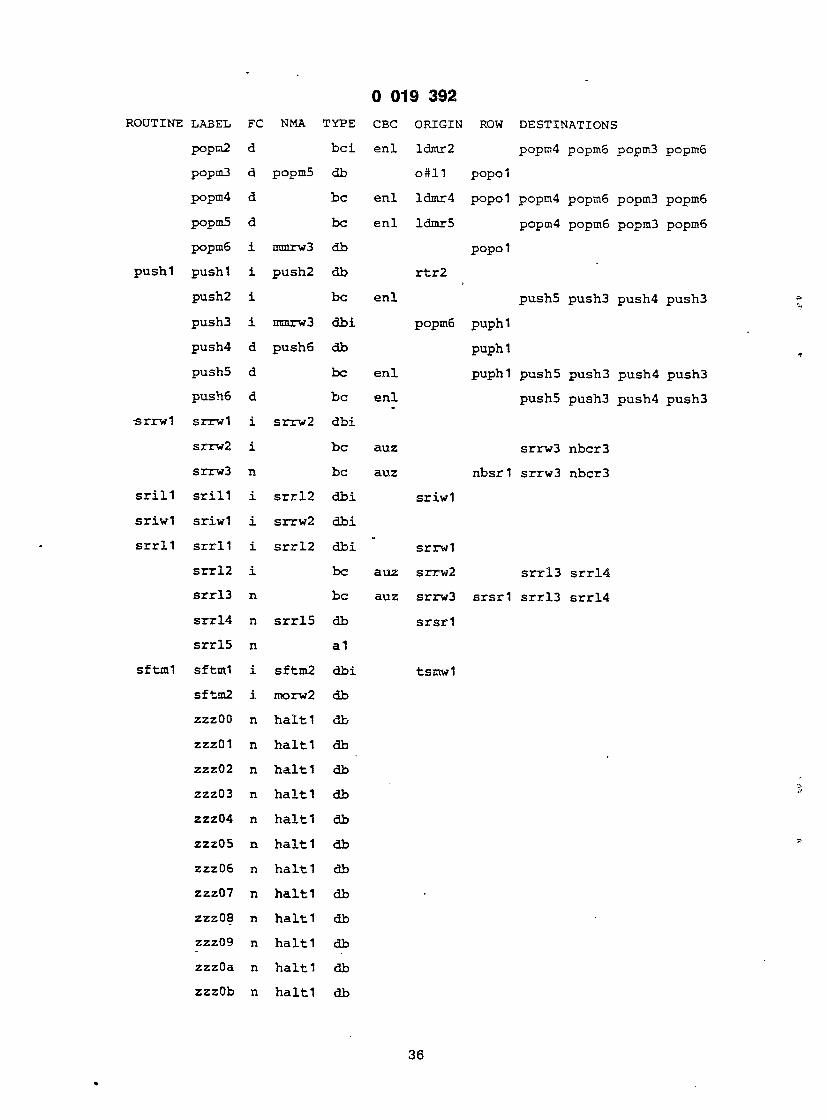
ROUTINE LABEL FC NMA TYPE
popn2 d b c i
popm3 d popm5 db
popm4 d b e
popm5 d be
popm6 i mmrw3 db
pushl pushl i push2 db
push2 i b e
push3 i mmrw3 d b i
push4 d push6 db
push5 d be
push6 d b e
•srrwl srrwl i srrw2 d b i
srrw2 i b e
srrw3 n be
s r i l l s r i l l i s r r l 2 d b i
s r iwl sriwl i srrw2 d b i
s r r l l s r r l l i s r r l 2 d b i
s r r ! 2 i be
s r r !3 n b e
s r r l 4 n s r r l 5 db
s r r l 5 n a1
sftml sftml i sftm2 d b i
sftm2 i morw2 db
zzzOO n h a l t l db
zzzO 1 n h a l t l db
zzz02 n h a l t l db
zzz03 n h a l t l db
zzz04 n h a l t l db
zzz05 n h a l t l db
zzz06 n h a l t l db
zzz07 n h a l t l db
zzzOa n h a l t l db
zzz09 n h a l t l db
zzzOa n h a l t l db
zzzOb n h a l t l db
0 019 3 9 2
CBC ORIGIN ROW DESTINATIONS
enl ldmr2 popm4 popmo popm3 popmG
o#H popo l
enl ldmr4 popol popm4 popm6 popm3 popm6
enl ldmr5 popm4 popm6 popm3 popm6
popo l
r t r 2
enl push5 push3 push4 p u s h 3
popm6 puph l
puph l
enl puphl push5 push3 push4 push3 enl push5 push3 push4 p u s h 3
auz srrw3 n b c r 3
auz nbsr l srrw3 n b c r 3
s r i w l
s r r w l
auz srrw2 s r r l 3 s r r l 4
auz srrw3 s r s r l s r r l 3 s r r ! 4
s r s r l
tsmwl
36

) 019 3 9 2
ROUTINE LABEL FC NMA TYPE
5 zzzOc n h a l t l db
zzzOd n h a l t l db
zzzOe n h a l t l db 0 zzzOf n h a l t l db
zzz10 n h a l t l db
zzz11 n h a l t l db '5 zzz12 n h a l t l db
zzz14 n h a l t l db
zzz 1 5 n h a l t l db 10
zzz 17 n h a l t l db
zzz l8 n h a l t l db
zzz 19 n h a l t l db 25
z z z l a n h a l t l db
zzz lb n h a l t l db
30 zzz 1c n h a l t l db
zzz ld . n h a l t l db
zzz l e n h a l t l db
35 z z z l f n h a l t l db
zzz20 n h a l t l db
zzz21 n h a l t l db
40 zzz22 n h a l t l db
zzz23 n h a l t l db
zzz24 n h a l t l db 45
APPENDIX d
go abbrev meaning rx register (data or address) designated by
Rx field in macroinstruction
55
60
rxa address register designated by Rx field in macroinstruction
rxd data register designated by Rx field in macroinstruction
rxh upper half (16 most significant bits) of register (data or address) designated by Rx field in macroinstruction
rxl lower half (16 least significant bits) of register (data or address) designated by Rx field in macroinstruction
rxdl lower half (16 least significant bits) of data 65 register designated by Rx field in macroinstruction
37
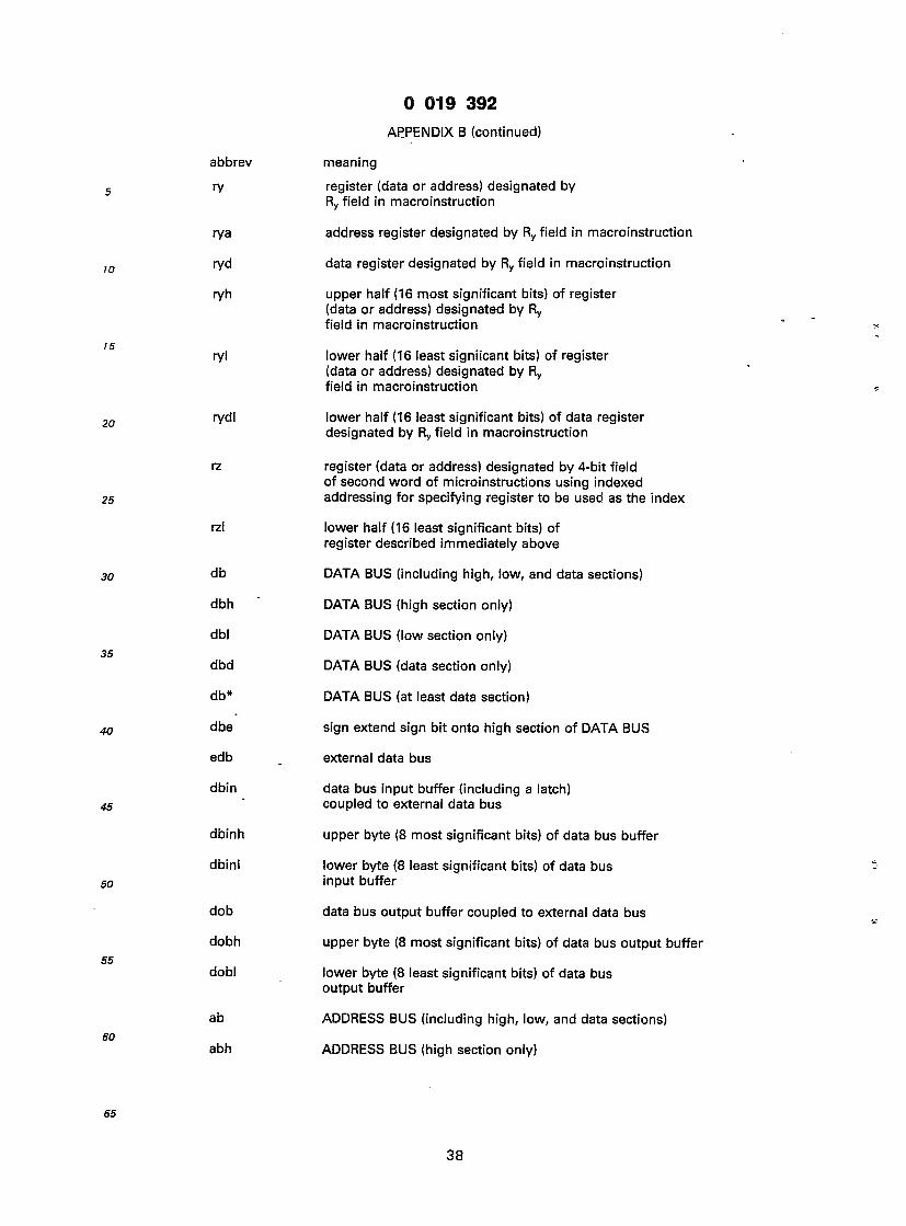
0 019 3 9 2
APPENDIX B (continued)
meaning register (data or address) designated by Ry field in macroinstruction
address register designated by Ry field in macroinstruction
data register designated by Ry field in macroinstruction
upper half (16 most significant bits) of register (data or address) designated by Ry field in macroinstruction
lower half (16 least signiicant bits) of register (data or address) designated by Ry field in macroinstruction
lower half (16 least significant bits) of data register designated by Ry field in macroinstruction
register (data or address) designated by 4-bit field of second word of microinstructions using indexed addressing for specifying register to be used as the index
lower half (16 least significant bits) of register described immediately above
DATA BUS (including high, low, and data sections)
DATA BUS (high section only)
DATA BUS (low section only)
DATA BUS (data section only)
DATA BUS (at least data section)
sign extend sign bit onto high section of DATA BUS
external data bus
data bus input buffer (including a latch) coupled to external data bus
upper byte (8 most significant bits) of data bus buffer
lower byte (8 least significant bits) of data bus input buffer
data bus output buffer coupled to external data bus
upper byte (8 most significant bits) of data bus output buffer
lower byte (8 least significant bits) of data bus output buffer
ADDRESS BUS (including high, low, and data sections)
ADDRESS BUS (high section only)
38
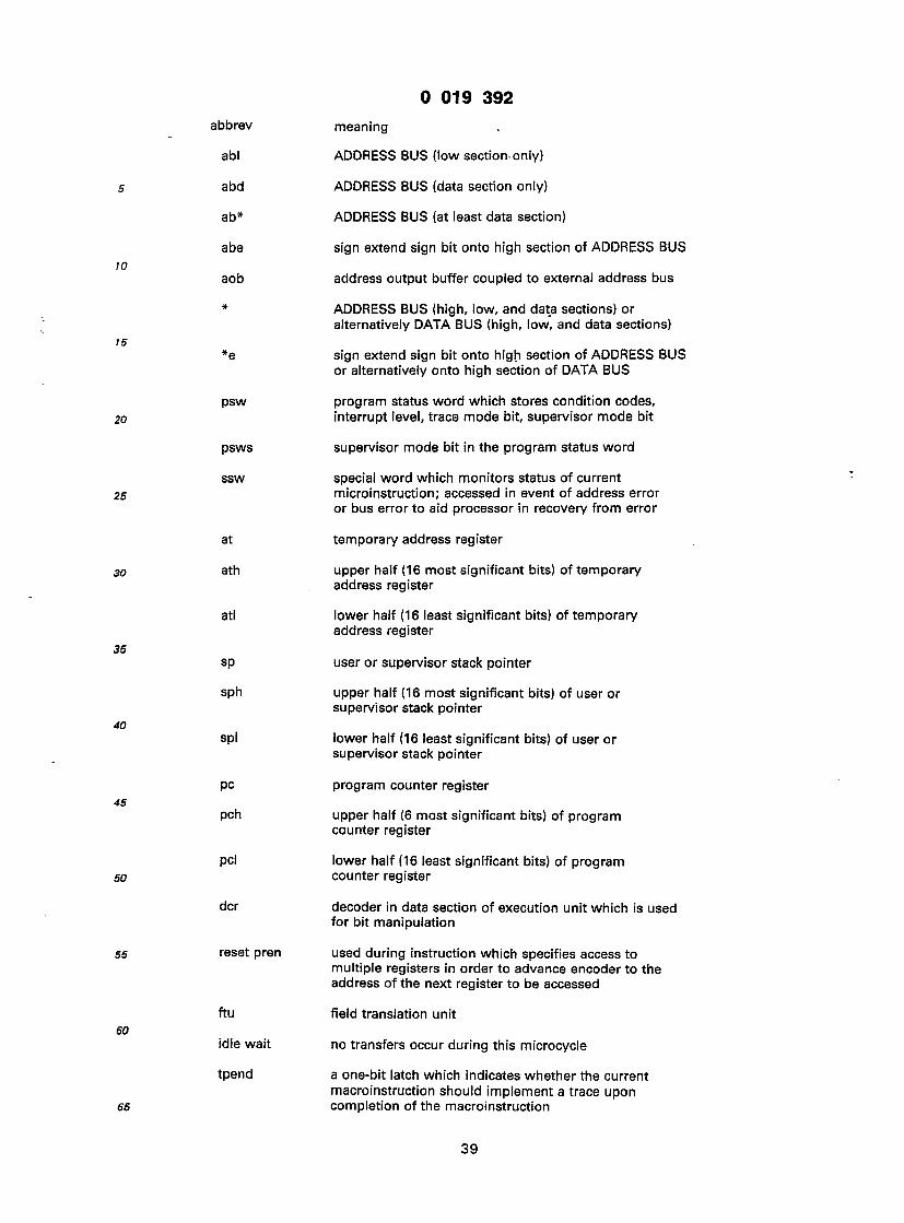
0 019 3 9 2
meaning
ADDRESS BUS (low section only)
ADDRESS BUS (data section only)
ADDRESS BUS (at least data section)
sign extend sign bit onto high section of ADDRESS BUS
address output buffer coupled to external address bus
ADDRESS BUS (high, low, and data sections) or alternatively DATA BUS (high, low, and data sections)
sign extend sign bit onto high section of ADDRESS BUS or alternatively onto high section of DATA BUS
program status word which stores condition codes, interrupt level, trace mode bit, supervisor mode bit
supervisor mode bit in the program status word
special word which monitors status of current microinstruction; accessed in event of address error or bus error to aid processor in recovery from error
temporary address register
upper half (16 most significant bits) of temporary address register
lower half (16 least significant bits) of temporary address register
user or supervisor stack pointer
upper half (16 most significant bits) of user or supervisor stack pointer
lower half (16 least significant bits) of user or supervisor stack pointer
program counter register
upper half (6 most significant bits) of program counter register
lower half (16 least significant bits) of program counter register
decoder in data section of execution unit which is used for bit manipulation
used during instruction which specifies access to multiple registers in order to advance encoder to the address of the next register to be accessed
field translation unit
no transfers occur during this microcycle
a one-bit latch which indicates whether the current macroinstruction should implement a trace upon completion of the macroinstruction
39

) 019 3 9 2
10
15
20
25
30
35
40
45
50
55
SO
65
abbrev meaning
inl latch which stores the interrupt level of the interrupting device upon recognition of an interrupt for subsequent transfer into program status word
trap stores vector which can be supplied to field translate unit for addressing a trap routine in event of trap condition (e.g. divide-by-zero)
abbrev meaning
corf correction factor for decimal arithmetic which can be provided to ALU
'sr c-alu-alue' shift right used in multiply operation; carry bit coupled to msb of ALU; Isb of ALU coupled to msb of ALUE
40

0 019 3 9 2
APPENDIX C
londitional Branch Choice
CBC VARIABLE SOURCE VALUES C1 CO KtMAHNS,
D I1 1 ire 0 0 0 1 1 1
1 auz eu 0 1 1 1 0 1
11 auz eu 0 1 1 1 0 0
2 c psw 0 0 1 1 0 0
12 c psw 0 1 1 1 1 0
3 z psw 0 0 0 1 1 1
4 nzl psw 00 1 0 nAz 10 0 1 x1 1 1
5 n psw 0 0 1 1 1 1
15 n psw 0 1 0 1 1 1
6 nz2 psw 00 1 1 n"z 1x,x1 0 1
7 msO eu,ird xO 1 1 ir[8]"alue[0] 01 1 1 11 1 0
8 m01 eu,ird 1xxx 0 0 auz"ir[8raiue[1:0] OOOx 1 1 001x 0 1 0100 1 1 0101 0 1 0110 1 o 0111 1 1
a ze eu 0 1 1 1 0 0
b nv psw x1,0x 1 1 r fv 10 0 0
c d4 dcr 0 1 1 1 0 1
1c d4 dcr 0 1 1 1 1 0
d v psw 0 1 1 1 0 0
e enl eu,ird 00 1 0 end*ir[6] 10 1 1 x1 0 0
1e enl eu,ird 00 1 0 10 1 1 x1 0 1
9 cc psw OF 1 1 1 T 1 1
19 cc psw OF 1 0 1 T 1 1
41
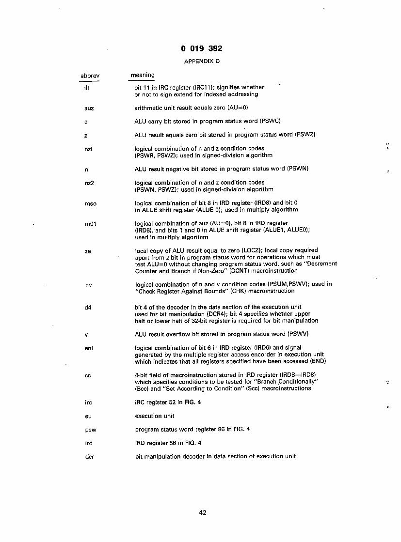
9 019 3 9 2
APPENDIX D
abbrev
ill
auz
c
z
nzl
n
nz2
mso
m01
ze
nv
d4
v
enl
cc
ire
eu
psw
ird
dcr
meaning
bit 11 in IRC register (IRC11); signifies whether or not to sign extend for indexed addressing
arithmetic unit result equals zero (AU=0)
ALU carry bit stored in program status word (PSWC)
ALU result equals zero bit stored in program status word (PSWZ)
logical combination of n and z condition codes (PSWR, PSWZ); used in signed-division algorithm
ALU result negative bit stored in program status word (PSWN)
logical combination of n and z condition codes (PSWN, PSWZ); used in signed-division algorithm
logical combination of bit 8 in IRD register (IRD8) and bit 0 in ALUE shift register (ALUE 0); used in multiply algorithm
logical combination of auz (AU=0), bit 8 in IRD register (IRD8),-and bits 1 and 0 in ALUE shift register (ALUE1, ALUEO); used in multiply algorithm
local copy of ALU result equal to zero (LOCZ); local copy required apart from z bit in program status word for operations which must test ALU=0 without changing program status word, such as "Decrement Counter and Branch if Non-Zero" (DCNT) macroinstruction
logical combination of n and v condition codes (PSUM,PSWV); used in "Check Register Against Bounds" (CHK) macroinstruction
bit 4 of the decoder in the data section of the execution unit used for bit manipulation (DCR4); bit 4 specifies whether upper half or lower half of 32-bit register is required for bit manipulation
ALU result overflow bit stored in program status word (PSWV)
logical combination of bit 6 in IRD register (IRD6) and signal generated by the multiple register access encorder in execution unit which indicates that all registers specified have been accessed (END)
4-bit field of macroinstruction stored in IRD register (IRDB— IRD8) which specifies conditions to be tested for "Branch Conditionally" (Bcc) and "Set According to Condition" (Scc) macroinstructions
IRC register 52 in FIG. 4
execution unit
program status word register 86 in FIG. 4
IRD register 56 in FIG. 4
bit manipulation decoder in data section of execution unit
42

0 019 3 9 2
APPENDIX E
duurev meaning condition
0 branch always, set always
1 never branch, reset always
2 HI high i-c
3 LS low or same z + c
4 CC carry clear c
5 CS carry set c
6 NE not equal i
7 EQ equal z
8 VC no overflow v
9 VS overflow v
A PL plus - H
B Ml minus n
C GE greater or equal n-v + n-v
D LT less H-v + n-v
E GT • greater z-n-v + z-n-v F LE less or equal z + n-v + n-v
APPENDIX F
Mnemonic Description Operand
ABCD Add Decimal with Extend 8
ADD Add Binary 8,16,32
ADDA Add Address 16,32 ADDI* Add Immediate 8,16,32
ADDQ* Add Quick 8,16,32
ADDX Add Extended 8,16,32
AND Logical AND 8,16,32
ANDI* Logical AND Immediate 8,16,32
ASL,ASR Arithmetic Shift 8,16,32 BCC Conditional Branch 8,16
BCHG Test a Bit and Change 16,32
BCLR Test a Bit and Clear 16,32
i

0 019 3 9 2
APPENDIX F (continued)
/Ineomonic Description Operand
3RA - Unconditional Branch 8,16
5SET Test a Bit and Set 16,32
3SR Subroutine Branch 8,16
3TST Test a Bit 16,32
;HK Check register against bounds - 16
;LR Clear an operand 8,16,32
ZMP Compare 8,16,32
;MPA Compare Address 16,32
ZMP\* Compare Immediate 8,16,32
2MPM Compare Memory 8,16,32
DCNT Decrement Counter and — Branch if Non-Zero
DIVS Signed Divide 32/16—32
DIVU Unsigned Divide 32/16—32
EOR Exclusive OR 8,16,32
EORI* Exclusive OR Immediate " 8,16,32
EXG Exchange Registers 32
EXT Sign Extend 8,16—16,32
JMP Unconditional Jump —
JSR Subroutine Jump —
LEA Load Effective Address 32
LINK Link and Allocate —
LSL,LSR Logical Shift 8,16,32
MOVE Move 8,16,32
MOVE CC Move Condition Code 16
MOVE Status Move Status Register 16
MOVE USP Move User Stack Pointer 32
MOVEM Move Multiple Registers 16,32
MOVEP Move Peripheral 16,32
MOVEQ* Load Register Quick 32
MULS Signed Multiply 16*16—32
44

0 019 3 9 2
APPENDIX F (continued)
Mnemonic Description Operand
MULU Unsigned Multiply 16*16—32
NBCD Negate Decimal with Extend 8
NEG Negate Binary 8,16,32
NEGX Negate Binary with Extend 8,16,32
NOP No operation —
NOT Logical Complement 8,16,32
OR Inclusive OR 8,16,32
ORI* Inclusive OR Immediate 8,16,32
PEA Push Effective Address 32
RESET Reset External Devices —
ROL,ROR Rotate without Extend 8,16,32
ROXL,ROXR Rotate with Extend 8,16,32
RTE Return from Exception —
RTR Return and Restore — Condition Codes
RTS Return from Subroutine —
SBCD Subtract Decimal with Extend 8
SCC Set Conditionally 8
STOP Stop —
SUBA Subtract Address 16,32
SUBI* Subtract Immediate 8,16,32
SUBQ* Subtract Quick 8,16,32
SUBX Subtract Extended 8,16,32
SWAP Swap Register Halves 16—16
TAS Test Operand, then Set 8
TRAP Trap —
TRAPV Trap on Overflow —
TST Test Operand 8,16,32
TST Test Operand 8,16,32
UNLK Unlink —
45
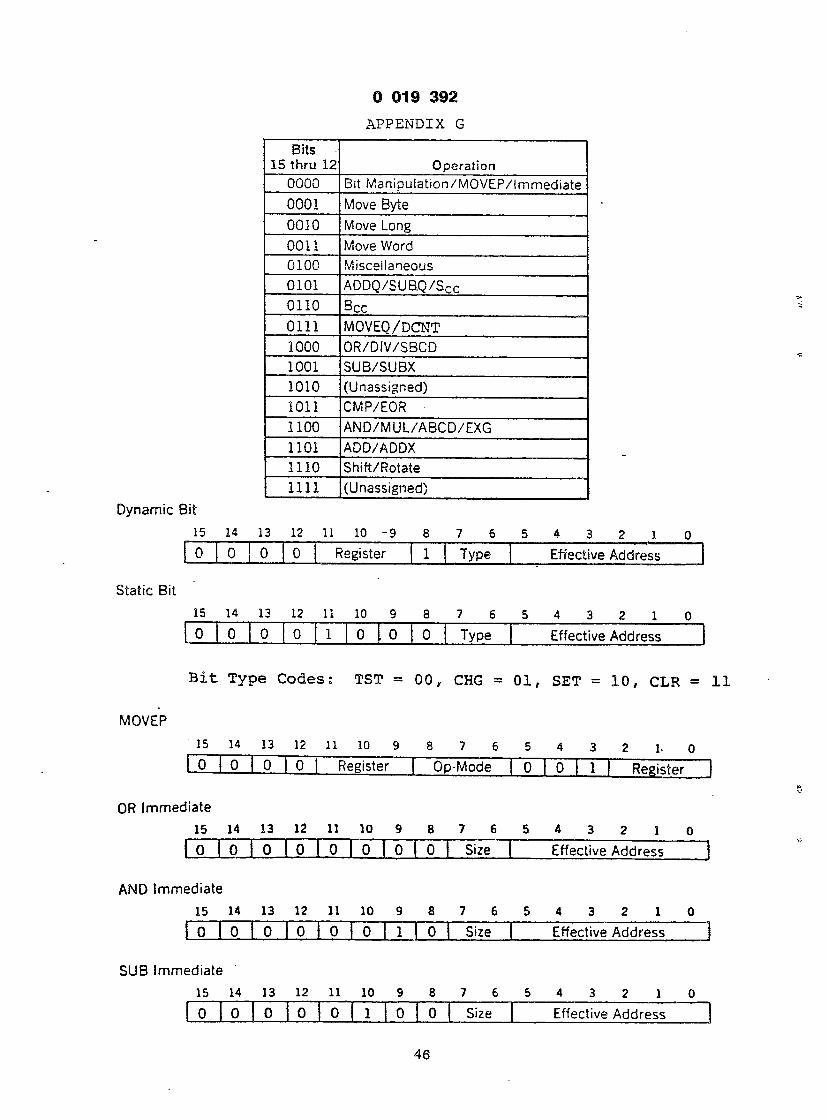
0 019 3 9 2
APPENDIX G
Bits 15 thru 12 Operation
0000 Bit ManipuIation/MOVEP/immediate 0001 Move Byte 0010 Move Long 0011 Move Word 0100 Miscellaneous 0101 ADDQ/SUB.Q/Scc 0110 Bcc 0111 MOVEQ/DCNT 1000 OR/DIV/SBCD 1001 SUB/SUBX 1010 (Unassigned) 1011 CMP/EOR 1100 AND/MUL/ABCD/EXG 1101 ADD/ADDX 1110 Shift/Rotate 1111 (Unassigned)
Dynamic Bit
15 14 13 12 11 10 -9 8 7 6 5 4 3 2 1 0 0 0 0 0 Register 1 Type Effective Address
Static Bit
15 14 13 12 11 10 9 8 7 6 5 4 3 2 1 0 0 0 0 0 1 0 . 0 0 Type Effective Address
B i t Type C o d e s : TST = 00 , CHG = 01, SET = 10 , CLR =
MOVEP
15 14 13 12 11 10 9 8 7 6 5 4 3 2 1 - 0 0 0 0 0 Register Op-Mode 0 0 1 | Register
OR Immediate
15 14 13 12 11 10 9 8 7 6 5 4 3 2 1 0 0 0 0 0 0 0 0 0 Size Effective Address
AND Immediate
15 14 13 12 11 10 9 8 7 6 5 4 3 2 1 0 O l O O O O O l O Size Effective Address
SUB Immediate
15 14 13 12 11 10 9 8 7 6 5 4 3 2 1 0 0 0 0 0 0 1 0 0 Size Effective Address
16
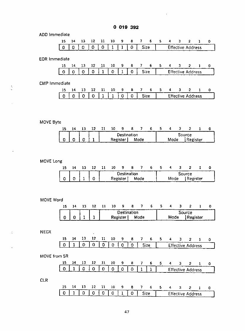
0 019 3 9 2
ADD Immediate
15 14 13 12 11 10 9 8 7 6 5 4 3 2 1 0 0 0 0 0 0 1 1 0 Size Effective Address
EOR Immediate
15 14 13 12 11 10 9 8 7 6 5 4 3 2 1 0 0 0 0 0 1 0 1 0 Size Effective Address
CMP Immediate
15 14 13 12 11 10 9 8 7 6 5 4 3 2 1 0 0 0 0 0 1 1 0 0 Size Effective Address
MOVE Byte 15 14 13 12 11 10 9 8 7 6 5 4 3 2 1 0
Destination Source 0 0 0 1 Register | Mode Mode | Register
MOVE Long 15 14 13 12 11 10 9 8 7 6 5 4 3 2 1 0
Destination Source 0 0 1 0 Register | Mode Mode | Register
MOVE Word
NEGX
CLR
15 14 13 12 11 10 9 8 7 6 5 4 3 2 1 0 Destination Source
0 0 1 1 Register | Mode Mode J Register
15 14 13 12 11 10 9 8 7 6 5 4 3 2 1 0 0 1 0 0 0 0 0 0 Size Effective Address
n SR
15 14 13 12 11 10 9 8 7 6 5 4 3 2 1 0 0 1 0 0 0 0 0 0 1 1 Effective Address |
15 14 13 12 11 10 9 8 7 6 5 4 3 2 1 0 0 1 0 0 0 0 1 0 Size Effective Address
47

0 019 3 9 2
NEG
15 14 13 12 11 10 9 8 7 6 5 4 3 2 1 0 0 1 0 0 0 1 0 0 Size Effective Address
MOVE to CCR
15 14 13 12 11 10 9 8 7 6 5 4 3 2 1 0 0 1 0 0 0 1 0 0 1 1 Effective Address
NOT . . 15 14 13 12 11 10 9 8 7 6 5 4 3 2 1 0 0 1 0 0 0. 1 1 0 Size Effective Address
MOVE to SR
15 14 13 12 11 10 9 8 7 6 5 4 3 2 1 0 0 1 0 0 0 1 1 0 1 1 Effective Address
NBCD
15 14 13 12 11 10 9 8 7 6 5 4 3 2 1 0 0 1 0 0 1 0 0 0 0 0 Effective Address
PEA
15 14 13 12 11 10 9 8 7 6 5 4 3 2 1 0 0 1 0 0 1 0 0 0 0 1 Effective Address |
SWAP
15 14 13 12 11 10 9 8 7 6 5 4 3 2 1 0 0 1 0 0 1 0 0 0 0 1 0 0 0 Register
MOVEM Registers to EA
15 14 13 12 11 10 9 8 7 6 5 4 3 2 1 0 0 1 0 0 1 0 0 0 1 Sz Effective Address
EXT 15 14 13 12 11 10 9 8 7 6 5 4 3 2 1 0 0 1 0 0 1 0 0 0 1 Sz 0 0 0 Register
TST
15 14 13 12 11 10 9 8 7 6 5 4 3 2 1 0 O i l 0 0 1 1 0 1 0 Size Effective Address
TAS
15 14 13 12 11 10 9 8 7 6 5 4 3 2 1 0 0 1 0 | 0 1 0 1 0 1 1 Effective Address
48

0 019 3 9 2
MOVEM EA to Registers
TRAP
LINK
UNLK
MOVE USP
RESET
NOP
STOP
RTE
RTS
TRAPV
15 14 13 12 11 10 9 8 7 6 5 4 3 2 1 0 0 1 0 0 1 1 0 0 1 Sz Effective Address
15 14 13 12 11 10 9 8 7 6 5 4 3 2 1 0 0 1 0 0 1 1 1 0 0 1 0 0 Vector
15 14 13 12 11 10 9 8 7 6 5 4 3 2 1 0 0 1 0 0 1 1 1 0 0 1 0 1 0 Register
15 14 13 12 11 10 9 8 7 6 5 4 3 2 1 0 0 1 0 0 1 1 1 0 0 1 0 1 1 Register
P
15 14 13 12 11 10 9 8 7 6 5 4 3 2 1 0 0 1 0 0 1 1 1 0 0 1 1 0 dr Register
dr ( d i r e c t i o n ) . : 0 - to USP 1 - f r o m USP
15 14 13 12 11 10 9 8 7 6 5 4 3 2 1 0 0 1 0 0 1 1 1 0 0 1 1 1 0 0 0 0
15 14 13 12 11 10 9 8 7 6 5 4 3 2 1 0 0 1 0 0 1 1 1 0 0 1 1 1 0 0 0 1
15 14 13 12 11 10 1 o 1 I 1 0 0 1 1
15 14 13 0 I 1 I 0
11 10 0 0 1 1
15 14 13 12 11 10 1 1 0 0
15 14 13 12 11 10 0 1 0 0 1 1 1 j 0 0 1 1 1 0 1 1 0
0 1
49
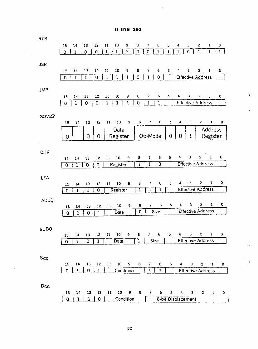
} 019 3 9 2
RTR
15 14 13 12 11 10 9 8 7 6 5 4 3 2 1 0
JSR
JMP
MOVEP
CHK
LEA
ADDQ
SUBQ
S e e
B c c
o i l o o 1 1 1 i T i l o I o 1 i 1 i f i 1 o 1 i 1 i 1 i 1
15 14 13 12 11 10 9 8 7 6 5 4 3 2 1 0
0 1 0 | 0 1 1 1 0 1 0 Effective Address
15 14 13 12 11 10 9 8 7 6 5 4 3 2 1 0
0 1 0 0 1 1 1 0 1 1 Effective Address
15 14 13 12 11 10 9 8 7 5 5 4 3 2 1 0
Data A d d r e s s
. 0 0 0 Reg i s t e r O p - M o d e 0 0 1 R e g i s t e r
15 14 13 12 11 10 9 8 7 6 5 4 3 2 1 0
0 1 0 0 Register 1 1 0 Effective Address |
15 14 13 12 11 10 9 8 7 6 5 4 3 2 1 0
0 1 0 0 Register 1 1 1 Effective Address
15 14 13 12 11 10 9 8 7 6 5 4 3 2 1 0
| o | i | o | 1 | Data 0 Size Effective Address
15 14 13 12 11 10 9 8 7 6 5 4 3 2 1 0
0 1 0 1 Data 1 Size Effective Address
15 14 13 12 11 10 9 8 7 6 5 4 3 2 1 0 0 1 0 | l Condition 1 1 Effective Address
15 14 13 12 11 10 9 8 7 6 5 4 3 2 1 0 0 1 1 0 Condition 8-bit Displacement
50

0 019 3 9 2
MOVEQ 15 14 13 12 11 10 9 8 7 6 5 4 3 2 1 0
Register Data
DCNT ( D i s p l a c e m e n t i s a l w a y s n e g a t i v e )
15 14 13 12 11 10 9 8 7 6 5 4 3 2 1 0
OR
DIVU
DIVS
SBCD
0 1 1 1 R e g i s t e r j 1 - D i s p l a c e m e n t
15 14 13 12 11 10 9 8 7 6 5 4 3 2 1 0 1 0 0 0 Register Op-Mode Effective Address
15 14 13 12 11 10 9 8 7 6 5 4 3 2 1 0 1 0 0 0 Register O i l Effective Address
15 14 13 12 11 10 9 8 7 6 5 4 3 2 1 0 1 0 0 0 Register 1 1 1 Effective Address
15 14 13 12 11 10 9 8 7 6 5 4 3 2 1 0 . Destination Source
1 0 0 0 Register 1 0 0 0 0 R/M Register
R/M (register /memory): register - register = 0. memory - memory = 1
SUB SUBA
SUBX
15 14 13 12 11 10 9 8 7 6 5 4 3 2 1 0 1 0 0 1 Register Op-Mode Effective Address
15 14 13 12 11 10 9 8 7 6 5 4 3 2 1 0 Destination Source
1 0 0 1 Register 1 Size 0 0 R/M Register
R/M (register/memory): register- register = 0, memory - memory = 1
CMP CMPA 15 14 13 12 11 10 9 8 7 6 5 4 3 2 1 0
1 0 1 1 Register Op-Mode Effective Address
51

0 019 3 9 2
EOR
CMPM
AND
MULU
MULS
ABCD
EXGD
EXGM
EXGA
15 14 13 12 11 10 9 8 7 6 5 4 3 2 1 0
1 0 1 1 Register 1 Size Effective Address
15 14 13 12 11 10 9 8 7 6 5 4 3 2 1 0
1 0 1 1 Register 1 Size 0 0 1 Register j
15 14 13 12 11 10 9 8 7 6 5 4 3 2 1 0 1 1 0 0 Register Op-Mode Effective Address
15 14 13 12 11 10 9 8 7 6 5 4 3 2 1 -0 1 1 0 0 Register O i l Effective Address
15 14 13 12 11 10 9 8 7 6 5 4 3 2 1 0 1 1 0 0 Register 1 1 1 Effective Address
15 14 13 12 11 10 9 8 7 6 5 4 3 2 1 0 Destination Source
1 1 0 0 Register 1 0 0 0 0 R/M Register
.ister/memory): register - register = 0, memory - memory = 1
15 14 13 12 11 10 9 8 7 6 5 4 3 2 1 0 Data Data
1 1 0 0 Register 1 0 1 0 0 0 Register
15 14 13 12 11 10 9 8 7 6 5 4 3 2 1 0 Data Address
1 1 0 0 Register 1 1 0 0 0 1 Register
15 14 13 12 11 10 9 8 7 6 5 4 3 2 1 0 Address Address
1 1 0 0 Register 1 0 1 0 0 1 Register
52

D 019 3 9 2
w
a d d ADDA
ADDX
15 14 13 12 11 10 9 8 7 6 5 4 3 Z 1 0
1 1 0 1 Register Op-Mode Effective Address
15 14 13 12 11 10 9 8 7 6 5 4 3 2 1 0
Destination Source 1 1 0 1 Register 1 Size 0 0 R/M Register
15
R/M (register/memory): register - register = 0, memory - memory = 1
Data Register Shifts
30
35
40
45
50
55
60
65
>0 15 14 13 12 11 10 9 8 7 6 5 4 3 c 1 U Coun t /
1 1 1 0 Register d Size i/r Type Register
15 Memory Shifts
15 14 13 12 11 10 9 8 7 6 5 4 3 2 1 0
1 1 1 0 0 Type d 1 1 Effective Address
Shift Type Codes: AS = OO.LS = 01, ROX = 10. RO = 11 d (direction): Right = 0, Left = 1 i/r (count source): Immediate Count = 0, Register Count = 1
Claims
1. A data processor for executing a plurality of macroinstructions comprising:— an instruction register (54) for storing a selected one of the plurality of macroinstructions to be
executed by said data processor: a control store (72) for storing a plurality of microinstruction routines for effecting execution of said
macroinstructions, each micro-instruction routine having a respective starting address, the last micro instruction of such a routine selectively providing an address selection control signal;
instruction decoding means (110) for decoding the macro instructions stored in said instruction register (54) and in response to the decoding, providing the starting address (A,) for a first selected one of said routines; address selection means (118) for providing to the control store (72) the starting address (A^ of said first routine in response to a first address selection control signal provided by the last micro instruction executed during the former macro instruction cycle;
at least one of said routines selectively providing a second address selection control signal; said instruction decoding means (110) also selectively providing the starting address (A2) of a second
selected one of said routines which has to be executed during the present macro instruction cycle in response to the decoding of said macroinstruction in said instruction register (54); said address selection means (118) providing to the control store (72) the starting address (A2) of said second routine in response to said second address selection control signal.
2. A data processor as claimed in claim 1 characterised by at least one of said routines also selectively providing a third address selection control signal; said instruction decoding means (110) also selectively providing the starting address of a third (A3) selected one of said routines in response to the decoding of said macroinstruction in said instruction register (54); said address selection means (118) providing to the control store (72) the starting address (A3) of said third routine in response to said third address selection control signal.
3. A data processor as claimed in claim 1 or claim 2 characterised by at least one of said routines handling an exception inherent in the macroinstruction stored in said instruction register (54); the data processor further including macroinstruction error detecting means (62) for detecting said exception inherent in the macroinstruction stored in said instruction register (54) and, in response to detection thereof, providing the starting address (Ao) of said exception handling routine and a further said address
53

9 019 3 9 2
selection control means (118) providing to said control store (72) the starting address (A„) of said exception handling routine in response to said further address selection control signal.
4. A data processor as claimed in any preceding claim characterised by at least one of said routines handling an exception which may occur during the execution of the macroinstructions stored in said
5 instruction register; the data processor including exception detecting means (68, 70) for detecting the occurrence of said exception during the execution of the instructions stored in said instruction register and, in response to detection thereof, providing the starting address (AqS) of said exception handling routine and a still further address selection control signal; said address selection means (118) providing to the control store (72) the
!° starting address (A0S) of said exception handling routine in response to said still further address selection control signal.
5. A data processor as claimed in any preceding claim characterised by at least one of said routines providing the starting address (78) of one other of said routines and a still further address selection control signal;
?5 said address selection control means (118) providing to said control store (72) the starting address of said one other of said routines in response to said still further address selection control signal.
6. A method for controlling a data processor adapted to execute a plurality of macroinstructions, the data processor including a control store (72) containing a plurality of microinstruction routines, each of the microinstruction routines including a plurality of microwords, the method comprising the steps of :—
20 receiving a macroinstruction and storing the macro instruction in an instruction register (54); decoding the macroinstruction and providing a plurality of decoded words as a function of the particular macroinstruction; selecting a first (A,) of the plurality of decoded words; addressing the control store with the selected first (An) of the plurality of decoded words for selecting one of the plurality of micro instruction routines;
25 deriving at least one selection signal from a micro word in the selected microinstruction routine; selecting a second (A-,, A2, A3) decoded word in response to at least one selection signal; addressing the control store with the selected second (A1( A2, A3) decoded word for selecting one of the plurality of microinstruction routines.
30 Patentanspriiche
1. Datenprozessor zur Ausfiihrung mehrerer Makrobefehle, enthaltend: ein Befehlsregister (54) zum Speichern eines ausgewahlten der Makrobefehle, die von dem
Datenprozessor auszufuhren sind; 35 einen Steurerspeicher (72) zum Speichern mehrerer Mikrobefehlsroutinen zur Bewirkung der
Ausfiihrung der Makrobefehle, wobei jede Mikrobefehlsroutine eine entsprechende Startadresse aufweist, wobei der letzte Mikrobefehl einer solchen Routine selektiv ein Adressenauswahlsteuersignal bereitstellt;
eine Befehlsdekodiereinrichtung (110) zum Dekodieren der in dem Befehlsregister (54) gespeicherten Makrobefehle und, in Abhangigkeit von der Dekodierung, zum Bereitstellen der Startadresse (A,) fur eine
40 erste ausgewahlte der Routinen; eine AdrelSwahleinrichtung (118) zum Bereitstellen der Startadresse (A,) der ersten Routine an den Steuerspeicher (72) in Abhangigkeit von eines ersten AdrelSwahlsteuersignal, das von dem letzten Mikrobefehl bereitgestellt wird, der wahrend des vorangehenden Makrobefehlszyklus ausgefiihrt wird;
wobei wenigstens eine der genannten Routinen selektiv ein zweites AdrelSwahlsteuersignal 45 bereitstellt;
wobei die Befehlsdekodiereinrichtung (110) auch selektiv die Startadresse (A2) einer zweiten ausgewahlten der Routinen bereitstellt, die wahrend des laufenden Makrobefehlszyklus in Abhangigkeit von der Dekodierung des Makrobefehls in dem Befehlsregister (54) auszufuhren ist; wobei die AdrelSwahleinrichtung (118) dem Befehlspeicher (72) die Startadresse (A2) der genannten zweiten Routine
so in Abhangigkeit von dem zweiten AdrelSwahlsteuersignal zur Verfugung stellt. 2. Datenprozessor nach Anspruch 1, dadurch gekennzeichnet, dalS wenigstens eine der genannten
Routinen auch ein drittes AdrelSwahlsteuersignal bereitstellt; die Befehlsdekodiereinrichtung (110) auch selektiv die Startadresse einer dritten (A3) ausgewahlten der Routinen in Abhangigkeit von der Dekodierung des Makrobefehls in dem Befehlsregister (54) bereitstellt; wobei die AdrelSwahleinrichtung
55 (118) dem Steuerspeicher (72) die Startadresse (A3) der genannten dritten Routine in Abhangigkeit von dem dritten AdrelSwahlsteuersignal zur Verfugung stellt.
3. Datenprozessor nach Anspruch 1 oder 2, dadurch gekennzeichnet, dalS wenigstens eine der genannten Routinen eine in dem in dem Befehlsregister (54) gespeicherten Makrobefehl innewohnende Ausnahme behandelt; der Datenprozessor weiterhin eine Makrobefehlsfehlerdetektoreinrichting (62)
60 aufweist, urn die in dem in dem Befehlsregister (54) gespeicherten Makrobefehl innewohnende Ausnahme zu ermittlen, und urn in Abhangigkeit von der Ermittlung derselben die Start addresse (A0) der die Ausnahme behandelnden Routine und ein weiteres AdrelSwahlsteuersignal bereitzustellen, wobei die AdrelSwahlsteuereinrichtung (118) an den Steuerspeicher (72) die Startadresse (A0) der Ausnahmebehandlungsroutine in Abhangigkeit von dem weiteren AdrelSwahlsteuersignal bereitstellt.
65 4. Datenprozessor nach einem der vorhergehenden Anspruche, dadurch gekennzeichnet, dalS
54

0 019 3 9 2
wenigstens eine der genannten Routinen eine Ausnahme behandelt, die wahrend der Ausfiihrung der in dem Befehlsregister gespeicherten Makrobefehle auftreten kann; der Datenprozessor eine Ausnahmeermittlungseinrichtung (68, 70) zum Ermitteln des Auftretens der Ausnahme wahrend der Ausfiihrung der im Befehlsregister gespeicherten Befehle, und, in Abhangigkeit
5 von der Ermittlung derselben, zum Bereitstellen der Startadress (AoS) der genannten Ausnahmebehandlungsroutine und eines noch weiteren AdrelSwahlsteuersignals aufweist; wobei die AdrelSwahleinrichtung (118) an den Steuerspeicher (72) die Startadresse (AoS) der Ausnahmebehandlungs- routine in Abhangigkeit von dem noch weiteren AdrelSwahlsteuersignal bereitstellt.
5. Datenprozessor nach einem der vorhergehenden Anspriiche, dadurch gekennzeichnet, daB '0 wenigstens eine der genannten Routinen die Startadresse (78) einer weiteren der genannten Routinen und
ein noch weiteres AdrelSwahlsteuersignal bereitstellt; wobei die AdrelSwahlsteuereinrichtung (118) dem Steuerspeicher (72) die Startadresse der genannten anderen der Routinen in Abhangigkeit von dem noch weiteren AdrelSwahlsteuersignal zur Verfugung stellt.
6. Verfahren zum Steueren eines Datenprozessors, der dazu eingerichtet ist, mehrere Makrobefehle 15 auszufiihren, wobei der Datenprozessor einen Steuerspeicher (72) aufweist, der mehrere
Mikrobeifehlsroutinen enthalt, von denen jede mehrere Mikrowdrter aufweist, enthaltend die folgenden Schritte: Empfangen eines Makrobefehls und Speichern des Makrobefehls in einem Befehlsregister (54); Dekodieren des Makrobefehls und Zurverfugungstellen mehrerer dekodierter Worter als eine Funktion des
20 speziellen Makrobefehls; Auswahlten eines ersten (A,) aus der Vielzahl dekodierter Worter; Adressieren des Steuerspeichers mit dem ausgewahlten ersten (A,) aus der Vielzahl der dekodierten Worter zur Auswahl einer der Mikrobefehlsroutinen; Ableiten wenigstens eines Auswahlsignals aus einem Mikrowort in der ausgewahlten Mikrobefehlsroutine;
25 Auswahlen eines zweiten (A1( A2, A3) dekodierten Wortes in Abhangigkeit von wenigstens einem Wahlsignal; Adressieren des Steuerspeichers mit dem ausgewahlten zweiten (A1f A2, A3) dekodierten Wort zur Auswahl einer der Mikrobefehlsroutinen.
Revendications 30
1. Processeur de donnees pour executor un ensemble de macroinstructions comprenant: un registre d'instruction (54) pour memoriser une macro-instruction selectionnee dans I'ensemble de
macro-instructions a executor par le processeur de donnees; une memoire microprogrammable ou de commande (72) pour memoriser un ensemble de
35 microprogrammes pour effectuer I'execution des macro-instructions, chaque microprogram'me comportant une adresse de debut respective, la derniere micro-instruction de ce microprogramme fournissant selectivement un signal de commande de selection d'adresse;
un moyen decodeur d'instruction (110) pour decoder les macro-instructions memorisees dans le registre d'instruction (54) et, en rSponse au decodage, fournissant I'adresse de debut (A,) pour un premier
40 microprogramme selectionne dans les microprogrammes; un moyen de selection d'adresse (118) pour fournir a la memoire microprogrammable (72) I'adresse de debut (A,) du premier microprogramme en r6ponse a un premier signal de commande de selection d'adresse fourni par la derniere micro-instruction executee pendant le precedant cycle de macro-instruction;
au moins un des microprogrammes fournissant selectivement un deuxieme signal de commande de 45 selection d'adresse;
le moyen decodeur d'instruction (110) fournit aussi selectivement I'adresse de debut (A2) d'un deuxieme microprogramme selectionne dans les microprogrammes qui doit etre execute pendant le present cycle de macro-instruction en reponse au decodage de la macro-instruction dans le registre d'instruction (54); le moyen de selection d'adresse (118) fournissant a la memoire microprogrammable (72)
so I'adresse de debut (A2) du deuxieme microprogramme en reponse au deuxieme signal de commande de selection d'adresse.
2. Processeur de donnees selon la revendication 1 , caracterise par au moins un des microprogrammes fournissant aussi selectivement un troisieme signal de commande de selection d'adresse; le moyen decodeur d'instruction (110) fournissant aussi selectivement I'adresse de d6but d'un troisieme (A3)
55 microprogramme selectionne dans les microprogrammes en reponse au decodage de la macro-instruction contenue dans le registre d'instruction (54); le moyen de selection d'adresse (118) fournissant a la m6moire microprogrammable (72) I'adresse de debut (A3) du troisieme microprogramme en rSponse au troisieme signal de commande de selection d'adresse.
3. Processeur de donnees selon I'une quelconque des revendications 1 et 2, caracterise par au moins un 60 des microprogrammes traitant une exception propre a la macro-instruction m^morisee dans le registre
d'instruction (54); le processeur de donnees incluant en outre un moyen de detection d'erreur de macro- instruction (62) pour detecter I'exception propre a la macro-instruction memorisee dans le registre d'instruction (54) et, en reponse a sa detection, fournissant I'adresse de debut (Ao) du microprogramme de traitement d'exception et un autre signal de commande de selection d'adresse;
65 le moyen de commande de selection d'adresse (118) fournissant a la memoire microprogrammable
55

9 019 3 9 2
(72) I'adresse de debut (Ao) du microprogramme de traitement d exception en reponse a i autre signal de commande de selection d'adresse.
4. Processeur de donnees selon I'une quelconque des revendications 1 a 3, caracterise par au moins un des microprogrammes traitant une exception qui peut se produire pendant I'execution des macro-
5 instructions memorisees dans le registre d'instruction; le processeur de donnees incluant un moyen de detection d'exception (68, 70) pour detecter
I'apparition de I'exception pendant I'execution des instructions memorisees dans le registre d'instruction et, en reponse a sa detection, fournissant I'adresse de debut (A0S) du microprogramme de traitement d'exception et encore un autre signal de commande de selection d'adresse; le moyen de selection
10 d'adresse (118) fournissant a la memoire microprogrammable (72) I'adresse de debut (A0S) du microprogramme de traitement d'exception en reponse audit encore autre signal de commande de selection d'adresse.
5. Processeur de donnees selon I'une quelconque des revendications 1 a 4, caracterise par au moins un des microprogrammes fournissant I'adresse de debut (78) d'un autre des microprogrammes et encore un
is autre signal de commande de selection d'adresse; le moyen de commande se selection d'adresse (118) fournissant a la memoire microprogrammable
(72) I'adresse de debut dudit autre des microprogrammes en reponse audit encore autre signal de commande de selection d'adresse.
6. Procede pour commander un processeur de donnees agence pour executer un ensemble de macro- 20 instructions, le processeur de donnees incluant une memoire microprogrammable (72) contenant un
ensemble de microprogrammes, chacun des microprogrammes incluant un ensemble de micromots, le procede consistant a:
recevoir une macro-instruction et memoriser la macro-instruction dans un registre d'instruction (54); decoder la macro-instruction et fournir un ensemble de mots decodes en fonction de la macro-instruction
25 particuliere; selectionner un premier (Ai) mot de I'ensemble des mots decodes; adresser la memoire
microprogrammable avec le premier mot (A selectionne de I'ensemble de mots decodes pour selectionner un microprogramme de I'ensemble des microprogrammes;
deriver au moins un signal de selection d'un micromot dans le microprogramme selectionne; et a 30 selectionner un deuxieme mot decode (A1( A2, A3) en reponse a au moins un signal de selection;
adresser la memoire microprogrammable avec le deuxieme mot decode (A1f A2, A3) selectionne pour selectionner un microprogramme de I'ensemble de microprogrammes.
35
40
45
50
55
60
65
56

0 019 3 9 2
INSTRUCTION REGISTER
INSTRUCTION DECODE
± ± ALU FUNCT REG I STER
A F I G . I
CONTROL STORE
ON & SELECTION
I I T l t t l < > C O N T
TIMING & SWITCH CONTROL SIGNALS
EXECUTION UNIT
FUNCTION CODE Z * A n z
MICRO ' CONTROL
STORE I
.18
NANO CONTROL
STORE
A 2 CONTROL
LOGIC
16
ADDRESS SELECTION
.26
BRANCH CONTROL
LOGIC -* X
.22
EXECUTION UNIT
F I G . 2
,14
IR SEQUENCE DECODER
X
INSTRUCTION REGISTER
n
r r r
IS 14 13 12 11 10 9 8 7 6 5 4 3 2 I 0 1 1 1 1 1 1 1 1 1 J 1 1
RX RY
R MODE E!A REG
MODE EiA REG
DATA
F I G . 6
1

n - | 1 V i
« \„ — = ^
n — i
f t
a1! i. ir
3
0 U a c c
5 2 an
<
/@V"
CM _>- _ 1- o
- u u * tn
u in
U3
f»»
CO
CD - < -
i 2 <
- r - z
on
in _u - _ U
H t i
i s
5 - — @ - * s <
o K
u a t r <
u. < H u *
yen < z
»_« Qh @ ~
—
r


2 o
UJ <
I
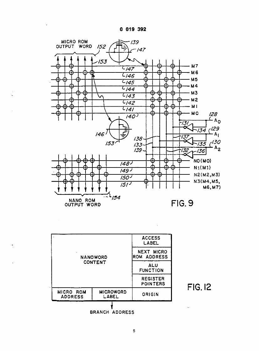
0 019 3 9 2
MICRO ROM OUTPUT WORD 1 5 2
NO (MO) N l ( M l )
N 2 ( M 2 , M 3 ) N 3 ( M 4 , M 5 ,
M 6 . M 7 )
NANO ROM OUTPUT WORD
' 1 5 4 F I G . 9
ACCESS LABEL
NEXT MICRO NANOWORD ROM ADDRESS
CONTENT ALU
FUNCTION
REGISTER POINTERS
MICRO ROM MICROWORD n m n w ADDRESS LABEL ORIGIN
F I G . 1 2
BRANCH ADDRESS
5
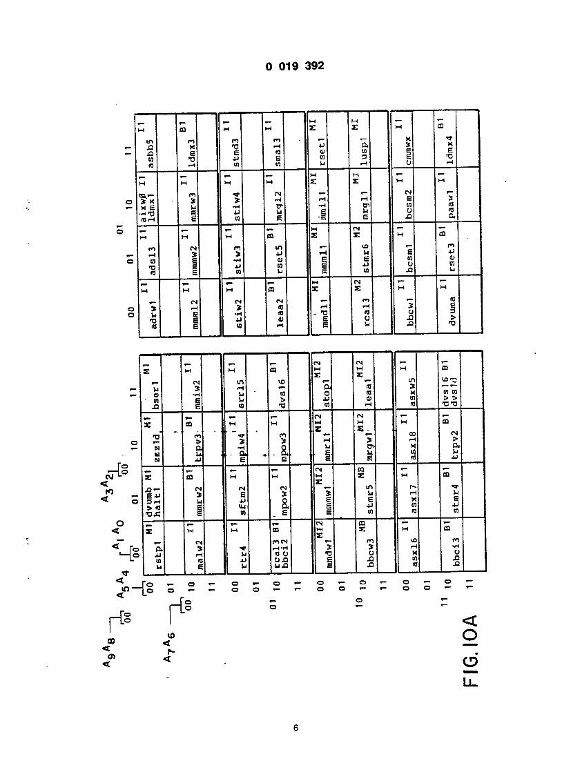
L I I- I I - I I- | I F M CD H M £
m II ci X II *0 E I E 'O II J-> r-i I W
ml
*
M
*
M fS
i
OS 3 E E
CQ
»@ c
I « I 1 *
CM L he m
*
I
- | = T
@ in I
II
It
«n
— I
J L
r
-
2 s
2 -
_ i 4
= 1
177
i J IL SI
I L_l I z
4 -
fl _ L I
< o
L l .
E •D .-I
S ra a
a fi 4J 0) 03 u
l-l
e >
*— CD
m m > > @CO
ffl
>
JJ
5
u E 4J (0
CD n o XI J3
o •—
< o
CD
L l .

r I
3
@
. J
E
. J H
i-l c 3
a a
1 1 w - r -
@9 1
4
J L D
@> — tu u . u o — — r ~i ST
2
3 u Z
2 o
@— 1 o •a a
r-i o •o a
u 3 >
to >
*r .c w 3 a.
*r cn o
»r E t-t 3 E
) *o E 3 >
<^ a o |
o l
o

I 019 3 9 2
m m ^ ^ - 2 2 2 S x x s s E * w,
- u a m u 5 j s j x - s m c r N m c 6 g x jj
.U « N JJ Oi U O « 0 t - i
M M M . M M H H E £ E £ E E E e e
m «- <- <n cn «- T T T ^ T O * » » > r-t J » » * p- X W X >D S U ,2 « « 5
( T J C B 3 U C XI <B g <0 f-i
M M M M H M H E M S : E E E E X s _ _
.- S * -h * g W -h * * * 12
E g xi go, «o XI U O E 0 1 m n -<r m »- *- £ 2 2 M C D C O E <n M E E f f l X £ X _ s_, _ CM CN (NT T — i- «- >- «J m
© » EH J n « a 2 £* J ^ © X 3J< X XN M DIM «J >0 O «J fl N CJ 0)0) 4 J + J H J N
o «- o <— © ^ © © - © *- o >— o >— o o »— © o »- - o © «— »- o © «- »-
O ^ w o o —
LU o
L l .

«3 C O — — «— M M
£ £
rH Id E «~ e u e n C 03 O N
M M M r £ £
m »- 1 — 1 - x ta. m £ 0 3 O N 0J >j Q. N- 05 T3| £ N
M M M £ £ £
r- i- - —I rH X i~ CJ C U N J3 X! N xi a
M M £ £
CN CN VO <U i-i is. ?s, ea.
03 N N a, > n n g "O N N
CN CN M M M £ £ £
r- i- d) J Xl -H «. g c j E N C O O N C W U N
CN CN M M M £ £ £ «- CN r- i- T3 S x u S <a. X g = 0 N
-WO > EX n (OrH g N CN CN H H M M £ £ £ £
i
@
-
Li
X ra <u a
H
CN ^ .— ( C 3
-1 E
E >o i-H
21 £ in E
M £
X ia 0) M
M :
a M £
ra E rH
ffl £
X m 0) Oj
1 - Q
- 2: > £ - o
o

1 I
o i~
£
£
£
cn v- Z
CN S
CN
— 4 I -
M J
2 ,11
,11
5
I n
CO — \- - 4 —
10
s i
_ 3
SI p">«w II w w II I
£
2 CN
n r- U) t> V
m co >
in u r-l o jQ
t — >— I £
CD CO > 2 .
m ta. co t»
HE.
u o Xi
e
CO @o
CD £
CO >
CO £ in u i-i o X
M £
i — r— < e Vj
CO £
co > 13
CN £
m IS. CO > •a
CN CD £ u o X
CN M £
U B u
o
Ll.

CN <N ID f— CJ CN sz ih ix <h ca. ih to • c 10 cr- w -w 3 u ra i» g & Cu JJ u tj g *- *~ CO M ffl M M M r £ £ £
CO. - ON CN N VCT E TJ 6 8 . . - I g Oj 3 ro CO rH 3 (0 S> OJ > (0 > Vj TJ Oj TJ U TJ jj <- — m h ea "in M M £ £ £ £
•V «- CN CN TJ <o <-t m ea. x t/1 CO «J TJ 10 CU > 0> E E > g TJ Qi M id <o T-i t- M CO H CO CN ffl DO £ £ £ CO £ co co Hd *r co ci i- u c&. cu ea. s to o to JJ to u > £t > CO > Id TJ C TJ U TJ 01
«— «— CN CN CN CN ffl M M M CO M £ £ £ £ p** co ro ^ cn EE S X 5 g ih 3 3 «3 t-l C 3 Vj > > CO JJ (TJ > g TJ TJ -«h u TJ E *- CN CN CN CN ffl M ffl M ffl M £ £ £ £ CJ CN in CN CN"J- TC — i E i } E TJ 0) CO 3 r-l Id 3 g > 0) > CO S > TJ TJ t-i TJ U g TJ M r- »- CN CN CN CN ffl M M M CO M £ £ £ £ en cj «— cn xt «- EE S »- r-i g x 3 3 CS M tH 3 Id t>> t o " * * CO > to TJTJ t-i di Id "D t-i »- «- CN CN CN ffl ffl ffl ffl M ffl £ £ £ £ a\ *r eu <»@> vo cn E m g o , g m 3 k 3 JJ 3 id > U > to > Id TJ to TJ Id TJ W
O Q o s
i Z S
1 1
© — — M 0>
~m W Wi "'"I u d u ra g W a cu 4J id tj g *- *~ CO M ffl M M M £ £ £ £
- ca. as cn n vcr 5 E TJ ea. m g Dj U 3 CO 0) rH 3 ra to s> oj > ra > id U TJ Od TJ Id TJ JJ *- — M M ffl M M M £ £ £ £
n @*r «— cn cn tj »- Cv »- ra r-i m a. x u tn ra ra tj to cu tO > 0> g g > g Id TJ Qi r-i U TJ T-l «- M CQ H CO CN ffl ffl £ £ £ ffl £ n co m nd *r r a n Ou *- u ea. a ea. 5 u to o to JJ to )d to > £> > to > Id Id TJ C TJ Id TJ 01
«— «— CN CN CN CN ffl M M M CO M £ £ £ £ N r*» CD CO »— f» CN " - " E E S X S g ih 0 ) 3 3 ra t-i cr 3 ^ to > > to JJ « t> g Id TJTJ -r-i -H Id TJ E r- i— CN CN CN CN ffl M ffl M ffl M £ £ £ £ N cj cn in cn rs t -<r > — i E > > E TJ tjl 0) ra 3 r - l l d 3 g d > to > r a g > tj U TJ T-l TJ I d g T J M »- •— CN CN CN CN ffl M M M CO M £ £ £ £ — en cj «— ro xt «- E EE S m g x Cn 3 3 «B M *H 3 Id d t>> t o " « « ra > to Id TJTJ T-l OJ Id TJ T-l
«- CN <N CN ffl ffl ffl ffl M ffl £ £ £ £ N 0\ *T 01 CO CO E m g Q , g m 7> 3 Id 3 JJ 3 id « > Id > W > Id Id TJ W TJ Id TJ W
o Q O S
d l
i Z S
1 1
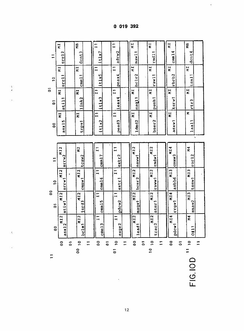
II il I n e l
r
r - i 1 — \tz — TZT-
r
si z
E
i @
2
. J J M
- 4 - - = 4 - 2 2
—

•— ID O Id o -
E J «- CS! J TJ •— N N U CU U} N N 0 E XI C-0 NJ E 't-l Vi
M E E
ffl CO. »- CN CN y- CN r-i r-l CN N N Id IT3 N n n o ra n n ca E --t n
H U M E E E
oo <u ea. »- «- t- i- iH J f-l C*3 N X f3 Id cn N E E tn N CS1 £ T-l JJ M CQ M E E E
r» a) «- «- - *- S E XJ ta tQ -w CU jQ n n E Q W n n g a ra
— »- CN CN M H W M H E E S »- cn cn «- -H > > TJ — HI 5 U Id jj xi ra ra jj ja ra e t-i u
i- *- CN fN M M H M M E E E «- CN «- CN S * * «- U E to la s o JJ E 0 «* Xj 03 r-t E O C
«- r- CN CN M M M M M E E E

D 019 3 9 2
\9Aq ~
A7A6A5A4 | A1AQ I rA3A2 'OO 01 10 11
30 0000 00
00 0000 01
00 0000 10
00 0000 11
r s t p l m dvumb dm zzzld m b se r l m
adrwl ads l3 aixwO d a s b b 5
push6 rbrb3 r c a l 2 • " r l q l l
'rmil2 rmi l3 rmml2 r m r l 2
00 0100 00 r t r 4 sftm2 mpiw4 s r r 1 5
00 0100 01 s t iw2 s t iw3 s t iw4 s tmd3
00 0100' 10 stmr2 stmw2 stmxl s t r w 2
00 0100 11 swapl swap2 tasml t a s m 2
00 1000 Ox mmdwl mmmwl mmrll s t o p l
00 1000 10 t a s r 2 t r ap2 t r ap4 t s m l 2
00 1000 11 t s r l 2 unlk3 unlk4 l i n k 3
00 1100 00 asxl6 asxI7 asxl8 asxw5
00 1100 01 bbcwl bcsml bcsm2 cmmw4
00 1100 10 cpdl2 cpml2 cp r l2 cprm2
00 1100 11 dcnt2 jmpal j s a l 2 malwl
01 0000 xx asxw2 roawl asxw3 l d m r 2
F I G . 1 1 A
14

0 019 3 9 2
oo 01 10 1 1
00 0010 00
00 0010 01
00 0010 10
00 0010 11
00 0110 00
00 0110 01
00 0110 10
00 0110 11
00 1010 Ox
00 1010 10
00 1010 11
00 11.10 00
00 1110 01
00 1110 10
00 1110 11
01 0000 xx
malw2 mmrw2 b t rpv3 b mmiw2
mmml2 mmmw2 mmrw3 ldmx3 b
mpil3 mulm6 b mpil4 popm6 db
mpiw3 dvum3 b rapol2 mpol3
r c a l 3 db mpow2 mpow3 dvs 16 b
l e a a 2 b r s e t 5 b mrgl2 s m a l 3
mrgml mulm3 b b t s r 3 b ms twl
dvs07 b dvs05 b mulml m u l r l
r c a l 3 b stmr6 b mrgwl l e a a l
dvumf b mulm5 b bcsr3 b push5 b
nbcml dvum3 db nn r l2 p a a l 2
bbci3 b stmr4 b t rpv2 b dvs 16 db
dvuma r s e t 3 b paawl ldmx4 b
dvumd b mulm4 b bcsr4 b push4 b
dvs10 b t r a d db pdc l l p d c l 2
aixw2 b bs r i2 aixwl e x g e l
F I G . II B
15

0 019 3 9 2
00 01 10 1 1
01 0001 xx dvumb db mmxwl nnrwl t r a p 3
01 0101 00 chkr4 b dvur3 nnml2 t a s r l
01 0101 01 peax5 mawl3 stmx2 ldmd3
01 0101 1x mpiw2 dcn t l aixwl d ' nnmwl
01 11 Ox xx t r a d b rorwl adswl romwl
10 0001 Ox mmxw2 b j s r x 2 b asxw4 b
10 0001 10 jmal2 dvume d dvs11 p i n l 3
10 0001 11 dvum5 db dvumb db dvum2 p i n w l
10 0101 Ox cmmw2 cpdwl ldmr5 smaw3 b
10 0101 10 dvum.9 b dvum9 db dvs l c b dvum7 db
10 0101 11 dvg13 b. dvgH dvumO p u s h 2
10 1001 00 j s r a l j s r d2 laawl ldmxS
10 1001 01 " l ead2 pead2 l i n k l roaw2 b
10 1001 1x dvume b e#H dvum5 b i t l x 4
10 1101 Ox mmxw3 b j s r x 3 b rmrwl sccb2 b
10 1101 1x dvum6 b dvumb b mmrw2 db dvum7 b
F I G . I I C
16

0 019 3 9 2
00 01 10 1 1
01 0011 xx
01 0111 00
01 0111 01
01 0111 1x
01 1 1 Ix xx
10 0011 Ox
10 0011 10
10 0011 11
10 0111 Ox
10 0111 1fl
10 0011 11
10 1011 00
aixw2 db malw3 d rmdw2 z z z l b
exgel d b s r i l bsrwl p i n w 2
b t s r 2 chkml chkrl c h k r 2
dvuml a d r l l dvur l s c c b l
aixw4 b malw3 ablwl aixwO
ablwl d a b l l 3 rmmwl a b l w 2
r r g l 2 rrgml rrgw2 r s e t 2
r s t p 2 r s t p 5 r s tw l r t s 3
e#w1 abwwl dvs 17 b adsw2
s r r l l b j sawi j s a w 2 . . j saw3"
nbcr3 b p e a a l ' peadl p i n l 2
dvs06 bcsr3 db l i nk4 dvs03 db
10 1011 01 dvs15 m a i n mal l2 m a l l 3
10 1010 1x r s t p3 r a l l 3 ralw2 r a q w l
10 1111 Ox rmr l l b c l r 4 b dvs03 dvs lb b
10 1111 1x srrw3 b j s r x l ldmd4 mmrl2
F I G . 1 1 D
17

0 019 3 9 2
0 01 10 11
0000 Ox
0000 10
0000 11
0100 00
0100 01 i t l x 2 i t l x 3 i t l x 5 i t l x 7
0100 10 ad r l2 morl2 stmwl b t s i l
1 0100 11 zzz1 7 zzz 1 8 zzz 1 9 z z z l a
1 1000 Ox l ead l maqwl bcsr2 mawwl
1 1000 1x mmrwl mmxwO morwl maww2
1 1100 xx pdcwl rrgwl asbb6 cmmw3
asx l2 s r iwl srrwl s r r w 2
rmrl3 r o a l 2 roa l3 r b a l 4
roml2 roml3 ro r l3 r o r m 3
cmml3 cmml5 cmml6 cmml7
P i e . l l t
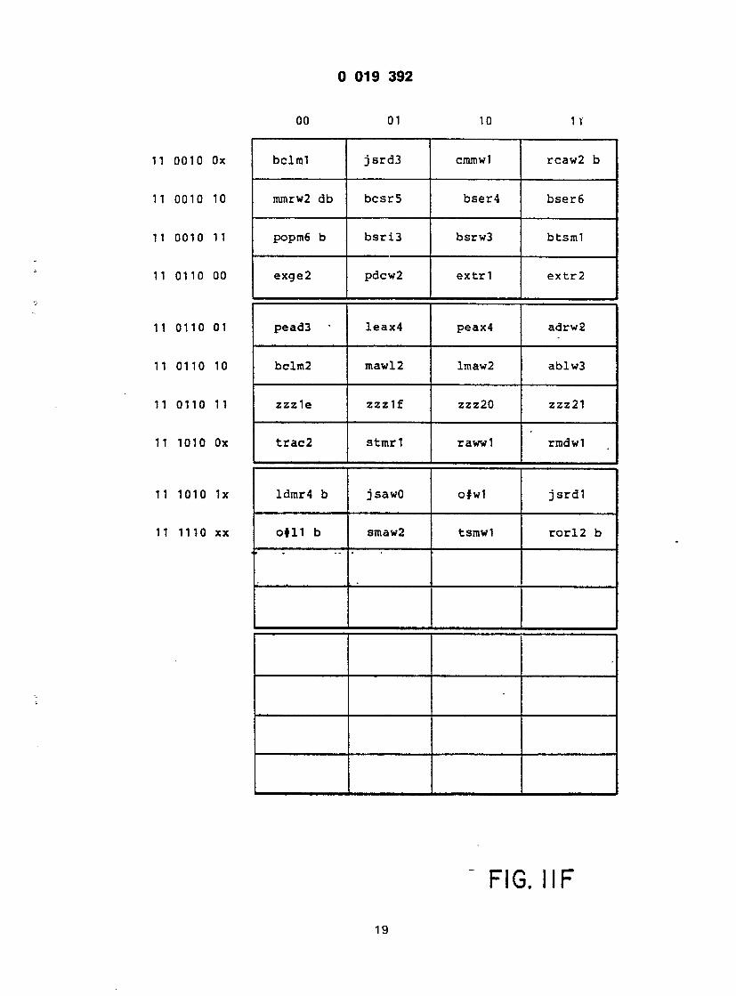
0 019 3 9 2
00 01 10 IT
I 0010 Ox bclml j s r d 3 cmmwl rcaw2 b
I 0010 10 mmrw2 db bcs r5 bser4 b s e r 6
1 0010 11 popm6 b b s r i 3 bsrw3 b t s m l
11 0110 00 exge2 pdcw2 e x t r l e x t r 2
11 0110 01 pead3 leax4 peax4 ad rw2
11 0110 10 bclm2 mawl2 lmaw2 ab lw3
11 0110 11 zzz le z z z l f zzz20 zzz21
11 1010 Ox t r a c 2 s tmr l rawwl rmdwl
II 1010 1x ldmr4 b jsawO o#w1 j s r d l
II 1110 xx o#H b smaw2 tsmwl r o r l 2 b
19
F I G . I I F
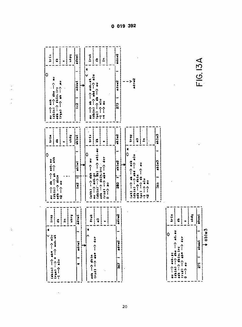
I 019 3 9 2
L 1 @ I ) |
- I OA • , t | a -
— • a A .a 0 I -o A A i
1 C I — I •-« a M -O 9 3 -d -a t- @ — « —
@
L*
@ i
• 3
* a 3 a I a 0 i a A * 2 I 1 • I A A -m 3 a I -i = • I A a a I A— I AA 1 * 1 1 3 ~9 a»-*l T
i
1 2
Ll . -
A V 3 4> @ a •D A ? 1 A a I » @ I — A * J> I -a 3 -n | a A A-> I A I C I I I - I .a a 3 -o @« CM a @» • +
I I I - i *» | @
a A I
a*
• u *<• A I A I u I I- I aal MM
I 5 «w r> -a A o I A
! •.' a 1 5 A ~ I ~ I C I — A x 1 « -a I *• AJB @ I @ 3 "B -O U — • ~ • — O
> a @
1 |_» a • • J
n @ CI
! 1 1
O 1 1 i- i n i c i 1 1 1
1
a* a a 0 A • I I A 4 1 -» I a a e I -a m 3 a i a a a I A 4 I - I I A A CI I I — — — I I
V 3 @» a • . A 0 I a ' a • i .a I « « A 3 I A - 1 ! ' a - . T A a* (-
i I n i a I I
I I • C a -m a
• —
(@ I -a 4» I -a I
a A I a — < u ja . *
- @* a .a A -a O I -BA a l i s A 1 a A- l 1 5 ' ; ?
.a ja <• I 3 -a t. a •—••@» ©
1 to I * ! -° i °
i
20

0 019 3 9 2
• — A . I A C I I a * C @a • * A U A | a. A ! • i ~> a ji m a a a >» u
J to O
DO r o
t o
u A a — i A c a i •« a 1 a e to a a * l u A r a. A 1 1 1 — 4» 1 ~< a AM* 3 TJ 1. • a • — (.
/ a.
e i u a I (- A J> .
A Jl ji I -o : @a I @ A A ~ I />i ( c I i
I ' !
-1 c. a u @O 3 A a I A : > t a a a " "
u I A A A al I M I C .PI I @« •» a i Jl K 9 « 3 -a »- •« a ~ — ~ I
- i I I I
Li a. I
: i :
= ' 1
° 1 n 1 c -*» i < i •< i i
a a> t- j» a 3 a a
3 * A — A I @ I C I - a A A tj 3 l a v « I • A a 3 A I a "A I I A a l t I A 3 1 - I I "« ji u I a s ti o.« a a — i o
a s
Ml 4» 1 1 TJ ~* 1 MN a l l J» 1 a 1 m s • 1 1 • j -e 1 i
\ u « ' a. -a - 31 3 (- a - A a I 0 I u a c AJ» , . 1 a e i — A Jl a I -a 3 t» i a A A - I A C M I — I a a 3 @» -o CM @ «» • +
E a Jl 4J i1 3 a <-> (- . a u a T> O A a I A I I A I I TJ I a « T» Jl .O 3 a -a a A I A A A t i l l I I i C « • t a @ » . @«».(.—
i n i i a i
(- A 3 I - A I i —a iN Jl -a 3 I J> -a m 3 i a a a • A I - A I I A A
3 ! ' ~ I I -4 Jl U a 3 -n u-~ n @» a • ~ i +
1

I I I e i =» — -» I -a a I- A -« —
1
0 " I
JJ A — r O I Jl I a I a I A j> I l a c I I — — I A @@ d I n 2 i v i a 4 I
A a i A *» i a »« i c i i i I - I I Jl -a I
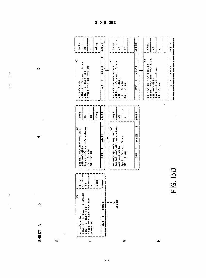
I I
ja - U C Jl A Jl 0 j ,
A A- I 1 e i
!
> i \
@ »
~ t a i A J3 I A J3 I « C I 1 T> C 1 — | | «H J3 A -a 3 I A -o "O i I i h : i j i s -a i a a r> i @ i a m A n i a i A ~ I A A W I A - I I A I C I I I I I C I I t — I t I I — — I jl jl t ja m u 3*OTJ**N I 3 TJ TJ
I I I I I I I I a. I I I CM I O- I I I M| u I n i i «- i « I « « I -a I i i i_ • i
A J3 _ I
3
— 7 ~ 7 i~ 1
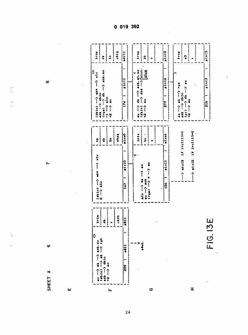
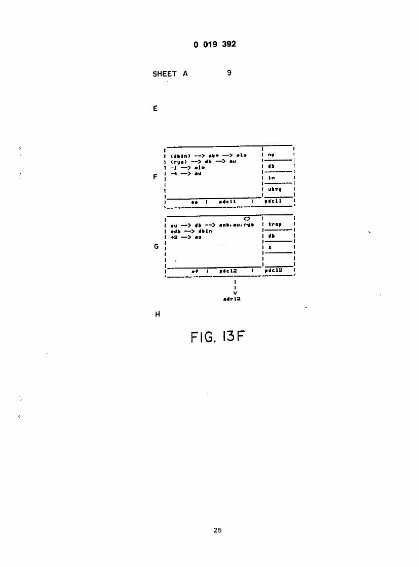
U19 OS*
Ifctl A ^
1 @ <d»ln> — > «b» — > alu I no 1 <r»«) — > db — > au 1 1 -1 — > alu 1 1 -4 — > au 1— 1
1 In 1 1 —1 1 ukr» 1 t 1
•• I pdcll 1 adell 1
O 1 1 au — > db — > aoli.au. r«a 1 trap 1 •db — > dbln 1 1 ♦2 — > au 1 <» j
1 i 1
•f | >dcl2 1 »dcl2 1
I I V
dr l2
1
F I G . I 3 F
^3

0 019 3 9 2
00
L l .
H Ui UJ X If)
a i d )
a u a @ -h A AC I I S . C @B • * A fr A I a. A I i I I 4> I — • A N @ a •» u a • • - t.
> 2
to u A .3 U I a — 1
A e a i A C @» A a
A 1 a. A I 1 1 - 4 .
26

e i — i fc XI I M -a I
a » -a o a
A I
A I a i A @» !
u
M I
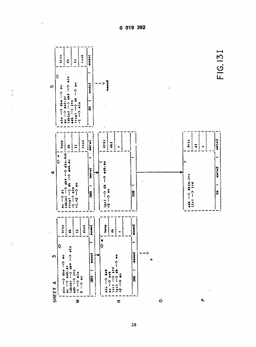
019 J »
3 3 r\ * l I I A * , ! a. a J3 • . u a 1 .o A f- a o I -» A • I I S A I I A— I I I C I — I « 3 jo a w
3 a A I
; I I
@ @ E I
J I D I i
i
1 )
a a u a a I I A
* i • -O 3 -o a A 3 u I A — A o. I I a I I I A - A I C -» I CM I — a I +
a — — l +
a a
i ~ i u O.CM — +
?! i
• i a l
— i- a
I
3 I <~ I E !
a i (- i c I
I
1 I CI I J - I I : i. I « j i 4» I -a »< I i I I
Ld 1 X ifi
a I I f » I u -O a. a • - u « « A u 3 •a o I x m a l a s a a a I A — I A i l c l l A I — I I 3 -o J= I rm 3 -a U »@« a a — a l o
I ! @ i 1 1
i i i i ', I
i
a j> -m v •a a 3 a A A a ?Al I A I I I I I 3 U u •* 3 •« O.N a a — — +

r 7 7
» £ ! - r fe ! i
e
Lx
d a @ 3 h* » 2 i ! •? 11 ^ A ! *' ! a - 1 •5 S - ! !5T! j , A 3 1 XI •>» tl u 1 A - A 1 -° @= = _ a. 1 1 • u a A A • HI mi a i i «
a~ a n i a i i I a i e - i n !>
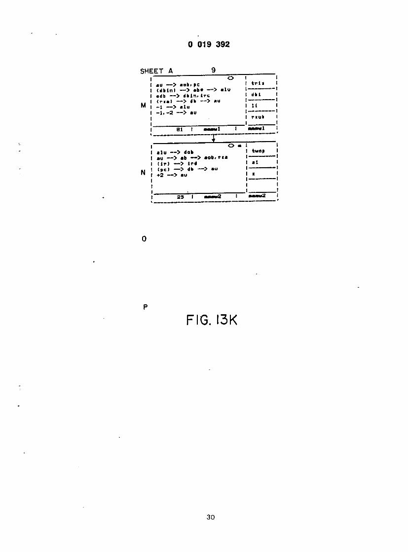
u i 9 os»*:
I t t I A J
I
I
1 ' u — > aob# pc 1 t r i i 1 dbin) — > ab» — > «lu 1— 1 db — > dbin. ire 1 dbi 1 r»a> — > db — > au 1 [ •1 — > alu 1 H 1 •1.-2 — > au I 1
1 riuk 1
Bl 1 aattml 1 waaMdl 1
O a t 1 ilu — > dob 1 *«°» • iu — > «b — > aob.ria 1- > ir> — > ird 1 •! | pc) — > db — > au 1 '"-
@2 -—> au ' *
29 1 annu7 1 mmmmS 1
I
F I G . I 3 K

i ~ 7 ~ 7 ~ 7 i "i I 1
- l i s - t \ 2 (. 1 a 1 C » — 1 1 i> — «
I I C I • j 1
= 2 - 1 0 0 * a j
*• o s a 1 a — a Ml x: a A — 1 * > A 1— • A 1 1- a i a i A i a i 1 ll l | CI A3 1 I x 1 — U a 1 X! a 1 1 a a. a C 1 xi ja -a 1 — — i xi -o a — l a A a A d 3 1 0 A3 1 @o 1 o 1 -o m 1 -o A A 1 — 3 1 l a i a r> i I I I a « -o I A A xi 1 A l l xi 1 1 ~A~ 1 A HI I -AA « I x i i c l l 1 - - C 3 1 <i 1 1 x: m •* i 1 1 3 — .£> X. 1 3 4» 4» XI 1 w a 3 -o -d i «« a a "a n 1 a a ~- a l j a — ~- — I + j
I I I I 1 1 1 1 ' 1 ! 1 1 « !
Ml 1 1 -M — Kl n 1. 1 xi 1 « i > ™ ». -. •. a - I ' ! " ! - a * 1 " r I a |
- u (. 1 V a . A .3 X!
xi A a l-* A a SI i . 1 1 i A xi < I a « C J
A3 A A xi — 3 i i i i -o i i A a «§ a A < A — A A ~ — 1 i A 1 c l I xi a l
1 1 1 a. i n 1 0 — 1 | 1 a « I •*» n — a 1 1 i e i i i — i
0 !
3 — S a »* »— a. — 3 - * 1 ( « i
a a — I 0 A a ti 3 * •a 1 o <-> 3 I a A a a N A 1 xi 1 -> A 1 A A « I a 1 I I 3 1 - 1 1 3^ u — a 3 o.x n a — a — 1 + i
>
) I @
> c > >

i i . l i - i - i - J 1 !
/ a l - J CM • !
» !
I l l 1 I I I : i : '. i l l
O. | | | -M — | B.I 1 i 01 □ i I I a m i o I •* I I — @ t J I l_ I I I
V Jl 3 @
I
u o 1 A *» 1 a 1 la « A a 1 ffl 1 1 A - 1 A 1 1 C 1 - 1 1 — a 1 i 3 Jl Jl X 1 •m 3 U -O U -« 1 « a -~ • ~ 1
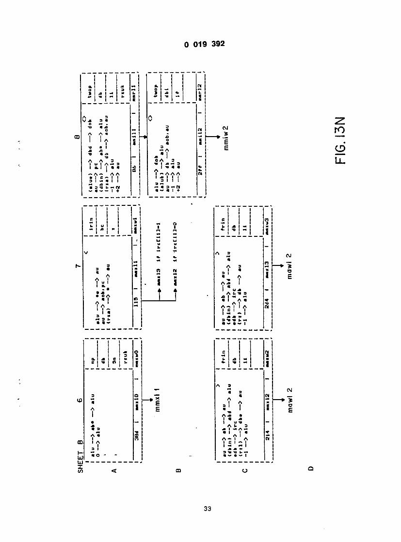
I I I ! ! a. I I M ~ \ 5- a I I o — t o t •»« i i 1 .O I - m (.1 1 I J I * I - 1 - i - •- i : * - -
o i n 2 Is !
I- i I -e
I I I 1 ci i i — !
- i - i - i . 1 z 5 ' j u u { u u
v j -* r j •*> «.
- ! * -
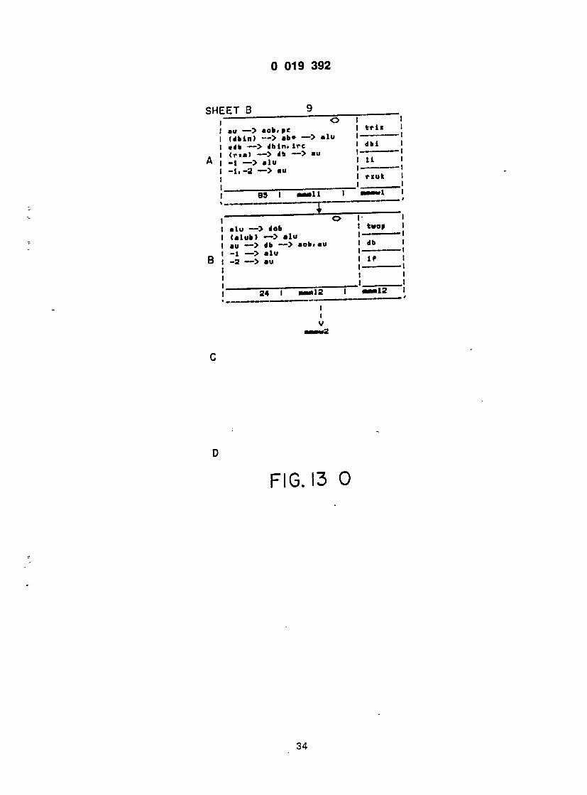
kin) — > «b» — > «1« i — > dbin. i re ia) — > ab — > au — > alu
,-2 — > au
lub) — > alu — > db — > aob.au — > alu
! — > au
;rii I
ibi
l i
rxuk
• m l 1 g 3 = = _ ,
2
F I G . 13 0

i "7 T~ i I E l l - * - * C j 1 - 1 1 3 J ~ !
0 0 • x: 3> 3« 3 « 3 " 11 k A • CJ jo A — > j— • A J
-
1 A - 1 A 1 I - 1 i I e -o 1 XI — — «• xt i a xi xi m tj xi » a « n 3 @o A « « — . » 0 A • l u A A A i A A PJ I 1 1 1 A U l ! 1 ' - - 1
9 3 J> b U 3 c «« n m -n — o.n « — I + i m • +
I

) 019 3 9 2
5 I 4? I
I I A I a « u * a A (- 0 I — A • ' ! A I A ~ I 1 E I — I — @ xi xi « 3 -D -O «-
I I - I I I - I
I a. I O I — S I xi - 4» I Tl » I
@ . A A I I
xi "o a 0 A-<3 • A I @ @ I I A I A A 1 — I I I — — I I u a> a o. u ~* tt m i
1 1 . 1 1 - . o i I a 3 1 xi 1 -« » *> 1 -o 1 — c 1 I
3 a @ -o XI 3 a — A A I I I I XI J> 3 @o • a 3 u A A •* A
*l ! " I A A I ~ — I N I a m I + MS* > 3 (. (. — — @ I +
CM
E £
• i i i s I I I - 1
» I I I » i — k> ja E I - i i
r o
CD
L l . V I 1 I
ro
co
UJ UJ X to
f — I
3 «
I
• 3 - « 3 t @ I A • I VI XI a»Ti xi u a xi A (. 3 0 I m A m a l ( a 3 A I a A— I A 1 6 I « I A I — M | | XI XI 3> I 3 -O (. M a — • — i o
UJ
CM
i D E
36

U19
i i . i I i - |
E t
0
3 o @ T» Ja 3 a m @ • A A I I I I M ja 3 tj a @ 3 * A A A I. I I @ I I I I \ A I I W I @« I +
J b b — -« I I +
i I I I I
CVi ! *
I e
O
@ i <@
o * i i u t i o. . • • OA • I A I I A ' I • 3 » h 3 iV
«@*) @ @ @ I I @ I
> H
-1
M @ — A * e i i — I j> * c Tl @ * A b A I a. A I 1 I I -w I - • a m a 3 t» b a a a b
I 4>
L.
m K- UJ U . X to
I I
I 3
c n — I a I T» - o
X E
a u A
a— i A c a i — • I -a e @a A a
A i a. A I I I — •» I a a m a 3 -a b a a • w b
@a*
TJ
UJ
o /

) 019 3 9 2
>HEET B
•u — > aob> pe •db — > dbin. i re (n i l — > db — > au (ryl) — > ab — > alu -1 — > alu -1. -2 — > au
232 I rmwl
I t r l s
I dbi
I 11
I r xuk
rawwl
mmmw2
3
F I G . I 3 S
3b

C I b I -a 1 » — I I 4> ! 1 I > I 1 U I -I I I I I a I
I -
A. ra I 1 I f l j n ji a. -a I -« — " A xi xi I -a 3 A @a I a • I A • i
a 3 I
1 1 1 1 1 1 @I 1 1 @* m j M I 1 3 b i XM -> I » m 1 -o " 1 — 1 b 1 1 1
2m
' T i T l H i
1 XI 1 la - 1 3 1 xi A 3 1 -a I a a o- 1 1 XI 1 A A A mi 1 — 1 1 1 1 x: 1 1 1 3 t - n i a - i + 1
i l l i i l l i » 1 i ) n i M | | | M| b | m | ». a 1 *. j a j - j b j
A J 3 1 m M 1 @ a mi • b a 1 u A b 1

= 1 ! ! - h I *• ! * i - i «@ If * r I - 1
@a o o \
3 3 3 -
. A « j
M
J i ~a 1 m 1 -o i 4» 1 TJ 1 M | I I I I I (-1
xi — i 0 4? !
5 j ro m n i
- = n — 1 —
?! - ! £ i i XI 1 XI @ — 1 xi -a 3 1 0 A m 3 1 • A l « « 4 1 II n 1 A 1 A A m| 1 — @ t 1 1 -> M | | 1 u a» 1 3 ak«lll 1 • — 1 + 1
I I I 1 ! ! !
xi i i n i — | 1 | M| — N _ _ i _ i _ i _ J i . i
A y ~ I V a_ I I 3 t @> mi
n u t-i
i
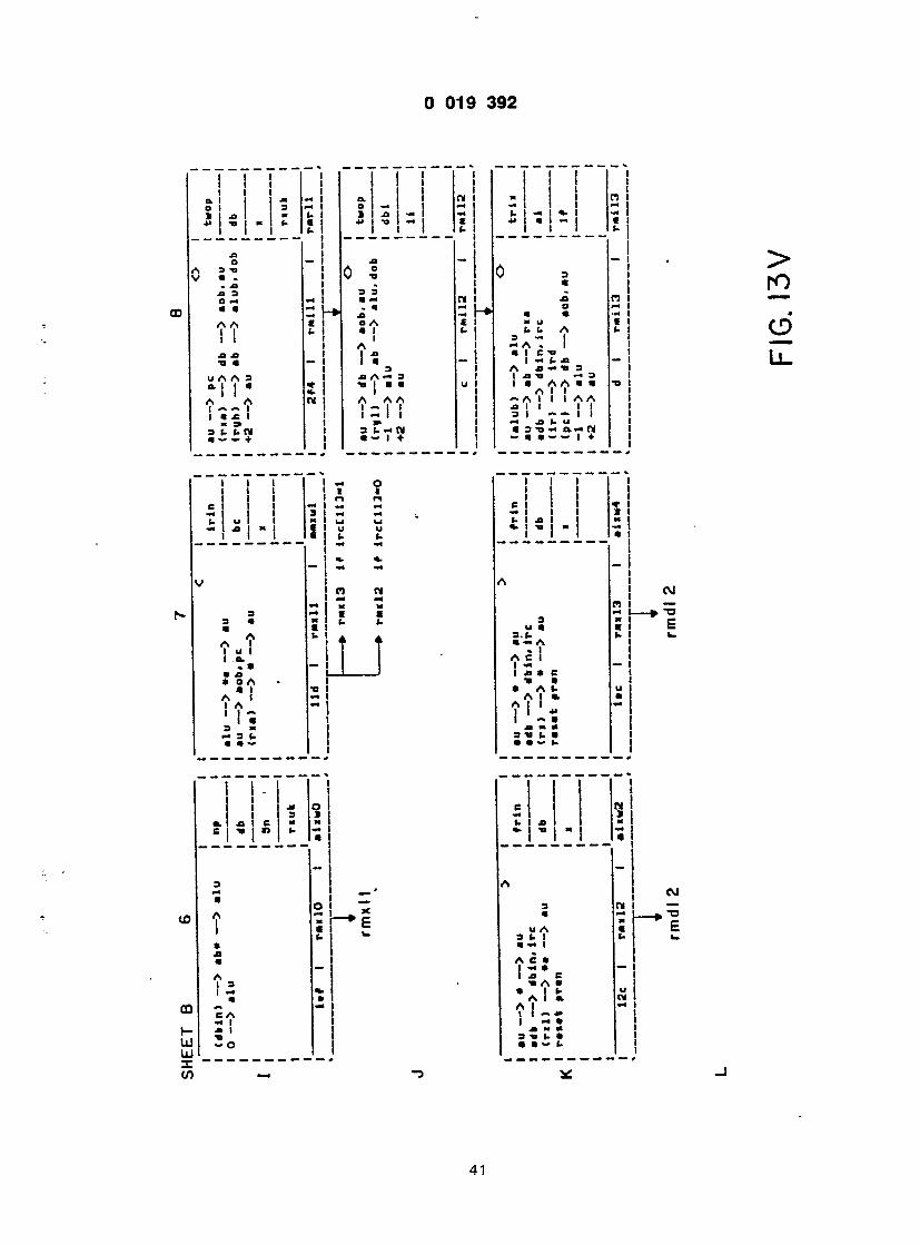
1 > 1 I I
*• i ' I - I - If i * I - I
1 - 1
l \ X
i - | !
U I " I « " « I d I " I I i U 1 I I I ' l l - 1 :
a a! fc
I . ! _
t i t I x i I i n i •1 i t i i (. 1 x | «@ m I 4» 1 a i — @ l 1 1 1 t-l
0 3 " | £
xi n i — — a a — I * t i A l\ O
a - j j a i c -a l 1 , 1 - (- x> - 1 LL. A J « 1 3 1 1 XI T» m 3 I la A A a a •«» 1 A l l — A 1 1 1 AA 1 XI 1 1 II 1 3 1 ~ — 1 1 1 ja U i* 1 1 3v< a«N 1 — a a — — @ l + j
- i l l s (. XI 1 j X
i l l a
A 1 i w
PS 1 — — 1 B> TJ 3 x 1 c u a " i t 3. (. <- 1 W a — a i . 1 1 A C 1 1 1 — — 1 1 xi a c i @o a 1 a a t- u i Ala , a A i 1 ~ • xi m a t 3 -a (- a 1 a a — i- j
1 1 e ti m s 1. XI x • - • o x — a
A C\J 3 W — a | p TJ
OA @ £ 3 (• 1 (- 1. a i A e a
@a A a • It- o Ala. N A 1 - 1 l « » 1 - a XI x @ 3 t> t- a
* !
CI 1 1 * 1 -» 1 1 1 XI (- 1 XI 1 j x | i l l a I
A 1 i w
pi i — — i a> TJ 3 x l c o a " i t 3. t <- l w a — a i . 1 1 A C 1 1 1 — — 1 1 xi a c i ti a 1 a a t- u I Ala . a A i 1 ~ • xi x a t 3 -a (. a 1 a a — i- j
1 1 C ti M S 1. XI x a> t» x — a
A OJ 3 W — a i t TJ
OA @ £ 3 1-1 1- L- a m l A e a l S * c
@a A a • 1 1- o Ala. N A 1 - 1 l « » 1 - a XI x x 3 t> t- a a . - t .

I 019 3 9 2
iHEET B 9 O I I
au — > aob.pc I t r l i I @ db — > dbin. ire I 1 (ria) r-> db — > au I dbi I (ryl) — > ab — > alu I 1 -1 — > alu 1 11 1 -1.-2 — > au 1 1
t r«u« 1 1 1
236 1 rmmll 1 rawaaii 1 A
O 1 1 alu — > dob 1 *«*oa 1 au — > db — > aob.au 1 1 - - 1 (r(|h) — > ab — > alu 1 db 1 -1 —> alu 1 1 -2 — > au 1 If 1
a 1 ram 12 1 r*«12 1 @ " "
r mmmw2
<
L
F I G . I 3 W
42

(. i j i i * t- " -"IS: 4> i -s i n a o 4> n n t i l ti i j_ j. _ . i - I
a @
TI JQ A 0 I TI A A a I i s < I A i @ 0 I A - I C
xi A @o I XI a I a o A 0 I ja A 3 l t» I a iS I 1 — A A I a I - I = I -c 1 3 M K
CM
E X r o
LL.
i
m a -i t- a «- « 4» tj n a i a
_ CM 0 3 t
" o " J, (9 E » 2? S - U
1 u • A fcA • 5 1 2~ 1 a tj c Jt -* M — 1 A tj a xi a 1 a! ' a s w J J3 CI A 3 «*. -*4 1 1
o a-
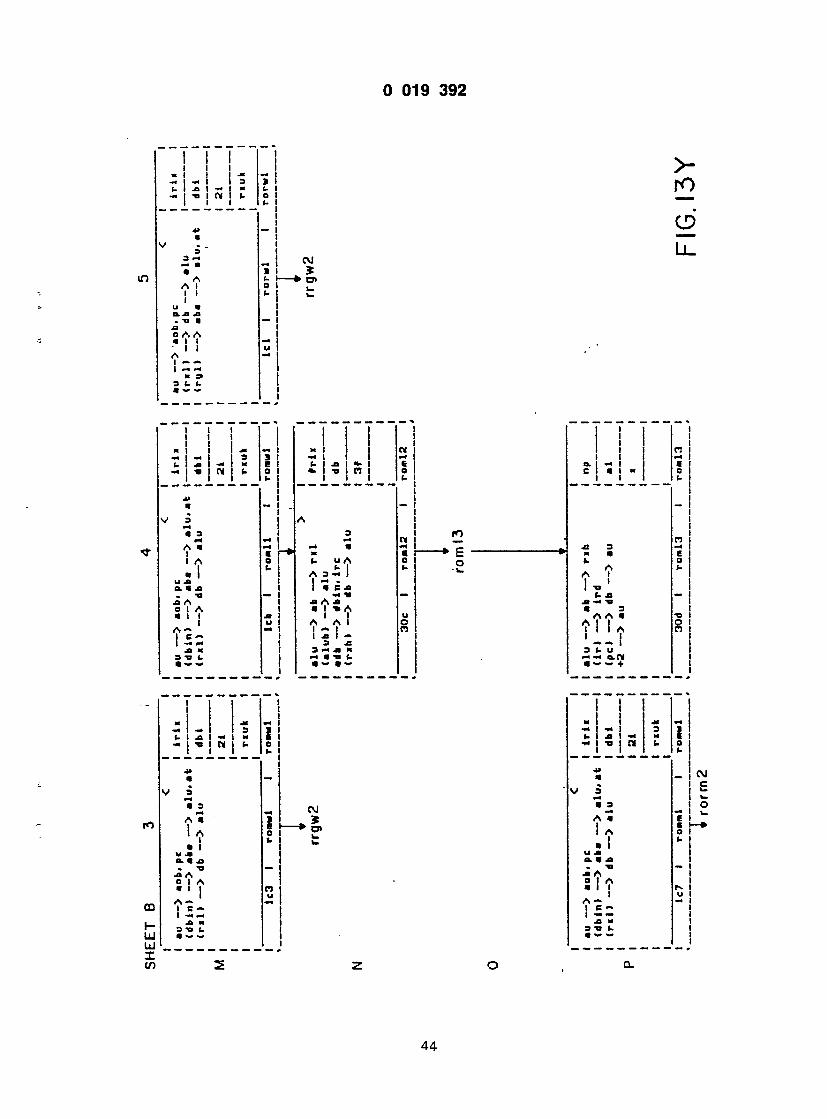
3 019 3 9 2
in
(- i xi i - ! !
3 3 — a a A A I I I I u a O.XI XI . u a XI O A A a l i I I A | , | m i @ 3> 3 fc (- a w
cm I s I
CM
r o
O
L i .
1 1 1 1 @@
— 1 — 1 3 j. | xi I — m - J "O j CM (-
A a i I A
o> a xi @o xi A e l A a l l I I M M XI * 3 -n (. a — "
: i ; : x I 1 1 CM M | | | M 1. 1 xi 1 «. 1 6 a. I -a I CI 0 I I I (-
A 3 M CM — a -< x @ @
t. u A 3 A 3 - i 1 M - I a c xi M TI — xi A xi a 1 -a A 1 1 u A A 1 O 1 " I C3 1 XI 1 - 3 x: 3 M XI X m a •« a •» a
ro * c: '
o M l> A i I I TJ (• XI
A a a ?! I A I I 3 U V M M O.CM a »» — +
i i o i M i c I O I 1- I I
ro
CD r- Ul UJ I CO
a 3 M a s M a a I A a l u XI a. a xi •v xi A 0 I A a i I
a — 1 c — I -MM xi x 3 -O U
I 3 -X | H CM I »-
CM
i i — I «
x 3 a 3 M A a I A • I
u XI a. a xi . Ta xi A 0 I A a l l I A — 1 c ~ I — — xi x 3 -a ». • ~ —
CM £
2
44

D 019 3 9 2
CO
i I M I — I (@ (@ I XI I - * - i n n =
A A I I I I . a -a XI o A A a I I I I A
3 (. (. a — «-
i l o
A . I C
A A ! ! S i Ti I I
ro » o o
c I I I I «- I i n i i i
3 3 M M a a A A I I I I
A A I !
o O
1 1 1 1 1 1 Ml 1 9 — 1 — i !• fc 1 XI 1 M I — j -a j N 3
3 3 m m a a A A 1 I
u B.XI XI - a n XI 0 A A a l l l l A 1 — — 1 m <-« M 9 3 U «@
M 3 3> a «- u b A I
I C-a M fc XI a -a 3 A a a A A I I ! ! I I a 3 XI U U m ti m a.n a a — — +
N r o
CD
L l .
10
CO r- UJ iu X CO
1 1 « 1 M M 3 !@ 1 X M M M | TI N (. 1
3 3 m a a A
. -a a O A A
3 U L. a — —
M M N 1 M M (. 1 (- XI (- o "a m o b (-
A M M M M u r* m tv O M u o t. U U «- M
7 c '2 . " 1 a ti i
« n ] M II (1 1 1 1
3 XI M TI a a l
ro @♦ i_ o
1 o. 1 xi 1 a. c j -a j n
3 3 M M a a A A @ i
A A I I I I
M 9 t. I-
45

0 019 3 9 2
SHEET B 9
M
N
au — > aob. pc I ir i i (n l ) — > db — > alu I I <ryl) — > aba — > alu. at I dbi
I 21
1 rxuk
lc9 I rorml 1 rorwl 1 i
alu — > * — > r»l 1 frix 1 • db — > dbin. ire 1 1
1 db 1
1 t 1
3«b 1 ror«2 1 rorl2 1
* r o r m 3
0
(ath) — > ab — > alu (rxh) — > db — > alu
np db
3*
30f I ror*3 I rorm3 ~J r o m l 3
F I G . I 3 A A
46

U19 3 9 2
I
3 I- U @ — — +
J J
2
j .
X)
00 r- UJ UJ X to

D 019 3 9 2
a a J- 3 M
a •» A A »
II I a A — — A
ji » 3 •» l. — a - — I
3 a
. T m a xi @» A
M M • «@
a a 3 @a A « 3
V V 3 M
M
a u
1
ra
3 >
< r o
L l ,
Id' Z
Jf* 3
4.1
XI I S A A
U i 7
CM £
1 a > T5
I s ' a. B.N «a* >a> }
W iJ:
i
ro 3 >
CD
48

0 019 3 9 2
• • . a a — @ @ A A I I I I a -a A A 3
il i • A — — A I I
XI M 3T I.M • ' I
-c P) @ O 3 n. U ~4 B > e xi w > T» Ti
m n o t-* o • • > > T> TI 3 • ~ A ~
U I m M c» « a. XI A - I • ~ O
* *
O ifl f a O O C H» <n k_ > > — T3 -o 4 4 4
3 a A I A I I I XI a XI 3 U A — 3
JZ I I 3 H 4» U ** «* a. «» I ♦
n C 3 >
10 o > T3
a. I xi = I T.
a a s . *" 3 _ a " • A I A I I
TI « A A 3
£ ! I a A — — A
3 I. (. — a—— l
fO L o (0 > T3
4> a XI 3 3 M •i a a s a A A 1
@a a M XI 3 @a -a A " 3 AA ( I ! AA 3 3 x H # I. X H »»» I +
n i • 1
-! jo
1 1 S i ?
ro
O (— UJ UJ X CO CO
.3 a A
3 A -> 1 @
- I
E
< r o
5 2 L l
49

0 019 3 9 2
- m n 3 U m „ o. -m m m. m c ~i a. C TI « 3 *. C TI M 4< C TI H 4> 4. m m
u -« a.xi r« n 3 * 1^ .3 * . 3 m @ — @ I— f> 3« m (— b> @ M — •» 4. M @ 4> 4i [ *? ~" " A — A —
3 1 A 1 1 i s 4» I @ 4> «@ — 1 * . — M%. — 41 3 TI A 3 im A h A 3 I A • * • 1 @ ««• A t " ti
1 A - A 1 A P) 1 A ft 1-1 I ' = 1 • u 3 e o. c m, m. CI 3 4> m m @ m r* - - 1 1 - — |
CD
xi I C
xi @ o @ A 3 I — A I • I J> I • OA xi 3 @a I xi @ m 3 I 1 - - A A I — A I A A 3 I ' I I
3 m 3 M @ 3 4» M * @ — *«. I I
X
3 4» « " f
• a ? * 1 - I f 4* U @ I OS.*.
P>
. 3 3 @
•» c a XI • M 3
3 @ M ft @ -O 1 I
3 a. . 3 4t) M O «
- f t O xi 3 @» 4» @ — 3
a a M 3 4* M
n @
n @ — * •
N M M
41 I 0 a @» 41 A A m 3 a ' I I 1 A AA 1 S3 I a u i. M 3 B.M M H
•
UJ UJ X
L l ! < r o
S 2
LL.
M « ? - t
* a4i a • I «• a f~ AA 3 m u M • «.M N
2t>J E o 4 5 5 «• *
50

SHEET C
0 019 3 9 2
9
8
(p»a>) — > *tu <pc) — > db — > «u -2 — > au
au — > ab — > alu. pc <«p) — > db — > au 0 — > tpand -1 — > alu -2 — > au
J
t r a p 3
F I G . I 3 A F
I np I db I
I ukuk I
IcO 1 tracl 1 tracl 1 1
np db
In
3*0 I trac2 I t rac2
51

0 019 3 9 2
CM
c
3 A « I I A . ! XI 3 a xi — 3 @a a a A I A A A I I I I I I I 3 W4 3 M w* a a I I
a I n i
N a 3 >
C
I l l I I i l l I I
x i l l ct m i a - 1 — 1 1 3 — 1 C b lx i l 1 <- *. »« 1 — 1 3 — i -o i m i | «- a I r> I > 1 1 1 1 1 1 -a
V 3 1 A a 1 x< *• 1 a a II @ a 3 I— »> 3 > u > A - a t . -a 1 —
C u XI • — Ml, — *o XI M 3 -O A a a A «r 1 -a A 1 a i A n | 1 l i 1 ~ 1 1 -> U 1 XI (- an I u <h 1 ^
CD < r o
CD
L l .
o H UJ Ui X to
• 3 -3 a a a a I I I xi a •a a 3 xi a -* 3 a A a. a a A I A A A l - l I I
a - + I I
Q. - O
V 3 a
3 a a l I A
am - ♦
— I
a
> "O
52
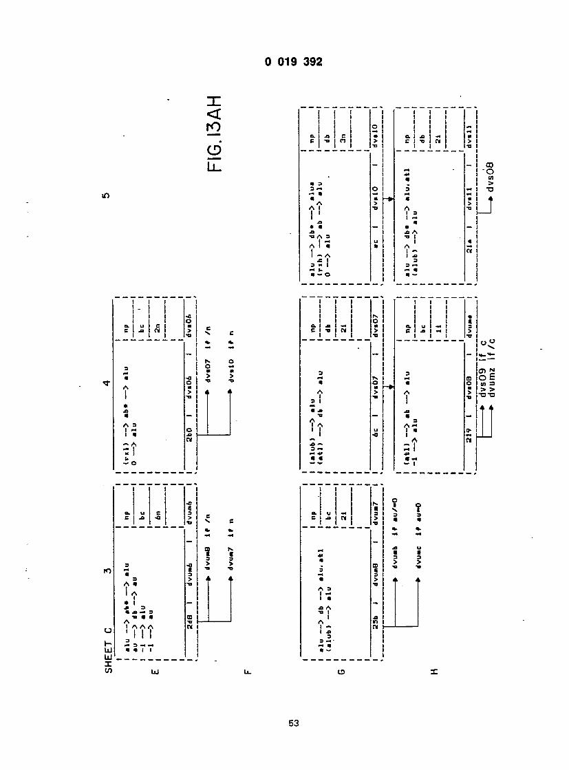
0 019 3 9 2
< r o
e >
L l .
I
O. XI i
C
• 3 3 m m a a A A I
@OAS I I — A @C | 3 " I -< I. a — o
I I 1 1 O 1 — 1 — 1 — 1 a a. 1 xi m a > C 1 TI M > I •o 1 I I 13 1
1 -~ ! i i — i - i i m t 1 4> 1 1 a i i . i O 1 3 Ml M | M Ml @ H» a @ > i > t @O A TJ 1 1 1 3 H 1 1 m | 1 a 1 — l a - l 1 x> A 1
u 1 "° i a ! a i a mi 1 1 - Ml 1 1 XI 1 1 3 1
1 { I « — i 1 1
CO o cn > TJ
1 1 1 • - 1 I I 1 1 1 1 1 1 1 a. 1 u 1 CI C 1 xi 1 M I 1 1
3 M a A I a XI a A 3 I M I a
f* — o
o o M a > 3 M a A I 3 I
A I A I 1
3 M M *» a a
— i J < j
C I a I
a 3 A — I a I A
— I
cn n O E « 3 3. > TJTJ ♦ 4
0- I
(_} I- LU UJ I 1/5
3 M a 3 A a I A I a i a 3 a xi m 3 ti a a A I A A A t i l l I 1 I 3 M 3 M M a a I I
3 > @ 3 >
! i
a. ! u m B j xi N
A 3 I M l a a A @a I I A I — I a 3 3 M - m a a ~
N I @ I 3 I > !
n i M H
3 a
53

9 019 3 9 2
I I j .m I in -o I k @ j M P4 @ I M (- xi { a. xi 3 a. xi 1 m 41 TI M 4> C U M > C T> I M 4> I -H | TI 1 •»
in -0 n XI M M W 0 — »-f> »• i-» — @ 4» ** *» M M M A 1 1 u - 7: * <- @» -« A -5 5 O A N I a 2 * "* 2 II p> — 1 n 1 @ 4» XI TI U a -0 -« — a » < •»
Tr — 2> o. a «-
< r o
S 2 L l .
a a a A
0 XI 3 ti xi a m 3 ti a a A A 1 A I A A ' I ' l l 3 3 M 3 *» M » a a.*. 1 T
GL a
@» : a*
aP *aa]
e I A 3
XI XI I C 0 a 3 -a XI A X 3 -a ti 1 a a A 1 ' 1 I A AA ' - 1 1 1 3 @*» a «- a 3 a -« M a— a — 1 1
n > a, a t-
10
O I- LU UJ X IS) UJ
54

U UI9 g a c
EET C 9
i
I i
in) — > ftu 1 nP e) — > db — > au 1
! — > au j -b J 1 i 1 I 1 1 c-idy 1 1 1
IdO 1 tr .pl 1 tracl \r
»cl) — > »b — > alu 1 «• J @ p) — > db — > au |-_--.— 1 — > alu ; @» J 2 — > au | 1 — > p»*t» 1 ln
89 1 trap2 1 trap2 1
O 1 1 lu — > dob 1 *"°» J u — > db — > aob. au _ 1 @@ " 1 tu — > ab — > alu 1 db I 1 — > alu 1 — 4 — > au 1 In
113 1 trapS 1 trapS 1
O 1 1 lu — > dob 1 *>*0P 1 u — > db — > aob.au. ap 1- " ' pch> — > ab — > alu 1 db 1 trap) — > *tu 1— 1 "
-1 — > alu j 1" J @2 — > au '
Ba 1 trap4 1 trap4 1
i t r a p 5
F I G . I 3 A J •
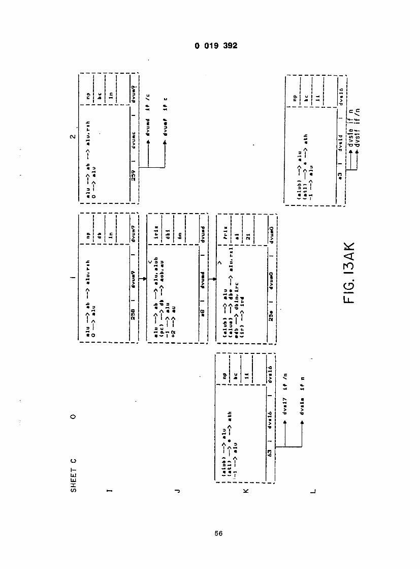
0 019 3 9 2
a, i u c | -
i Xi • 3 A a I A I a l m a o
A 3 I * A 3 I A — ' I •
— A xi ~ I a - I
I
rs I I
I a I
E I 3 I > I
3 >
ED I S I
xi I e
3 5 M «
M @ @ A t I I XI XI "B 3 @ -<3 A @ @ A I I AA 3 U M O.M M @ - I +
A I I u (@ 3 * — M XI . 41 C* — <- A A xi m
3 3 «@• M M XI (. < < 1 « a
* < @* i M
< r o
O
L l .
h- Ul hi X CO
a. u
A 3 I M I a a A 3 I A — I I a I - A xi — I 3- I •a -** a a —
> I
- i @ i > i
pj
> >
4
56

1 1 1
„l A C 1 -n 1 I C I
O > it V.
3 3 3 O
>o 3 CO » >
I *
; l_

M i !
-a - A @• CM 1 • — @ _ i xi A A A 0 1 -a A xi 1 a • i a -a I « A l u . A — 1 -t A — A C i - I 1 1 - • 1 •« 1 • XI XI 9 M a -o -o ». a n a — • — a «. +
I I I 1 I I I .1 i 1 . - ! . I l l
.
-a . i AX - I 15
xi A xi 1 xi 0 1 TI A 1 XI •» 3 « 1 1 W j -O @ ( A 1 @» A 1 A- - A I A 1 -S ' • I 1 I
XI XI 9 i XI a w e i s i n • *»•»» j m a +
3 S 1 *• 4> •< I 2. 1 I I CI .
II — — > 1 1 3 A 3 l-L- - a .1 «. XI t s
m XI — xi "o A a I 3 • a . - 3
1 - -a 1 U H 3 «. t- * « N» W 4
1 1 1 1 1 a. i n « ! ! * O 1 -4 X x | | 3 U j XI — C I X I *» 1 @» « a. 4 > i a l H a. 1 @ 1 1 C
0 0 a . H 3 U n a * a i _^ - A X a -h r+ xi i a> o 1 u a. A l a c 1
~ 1 A xi . c 1 a e i — XI — 1 — t- — xi xi 1 A xi m o ti a xi I n 3 a A a u -a i a a « A 1 W A I <r A 1 1 A A- I A I ' - l " l - ' - l a u xi xi u 3 @» a.<r 3 i i - n «•«»+ •*•••-@ +
n a. xi c a e <c > @a
° 5 " ♦ *" m @ I a > a >
A 1 XI 3 ~ a m a u A « I f •X) aa« a I
I a. i I I n I o l - I ! XI U XI I — *> I 1 a j a. I J t i_ @ I
I I M
— I A. 5xi - I
XI XI TJ i o ti a xi a a a u @@ A I n A I I A A' I I - \
I 4 3 t a

0 019 3 9 2
SHEET C 9
J
O I alu — > dob I twop (alub) — > alu I au — > db — > aob.au I db rtu — > aba — > at I -1 — > alu 1 * -4 — > au 1
29f 1 trapa 1 i t l x4
O 1 1 t r l x
(at) — > db — > aob.au 1 db au — > pc 1 •db — > dbin 1 x ♦2 — > au 1 raaat pran 1
1 2f« 1 trap& t ld»d4
1 1 V
j a a l l
K
O 1 au — > aob 1 t r i n (dbin) — > db* •— > au 1 •db — > dbin. Ire 1 db (rua) — > ab — > au 1 — 1 @ 1
1 X 1 1 rxry 1
lib 1 apill 1 adawl
mpil 2
F I G . I 3 A N
59
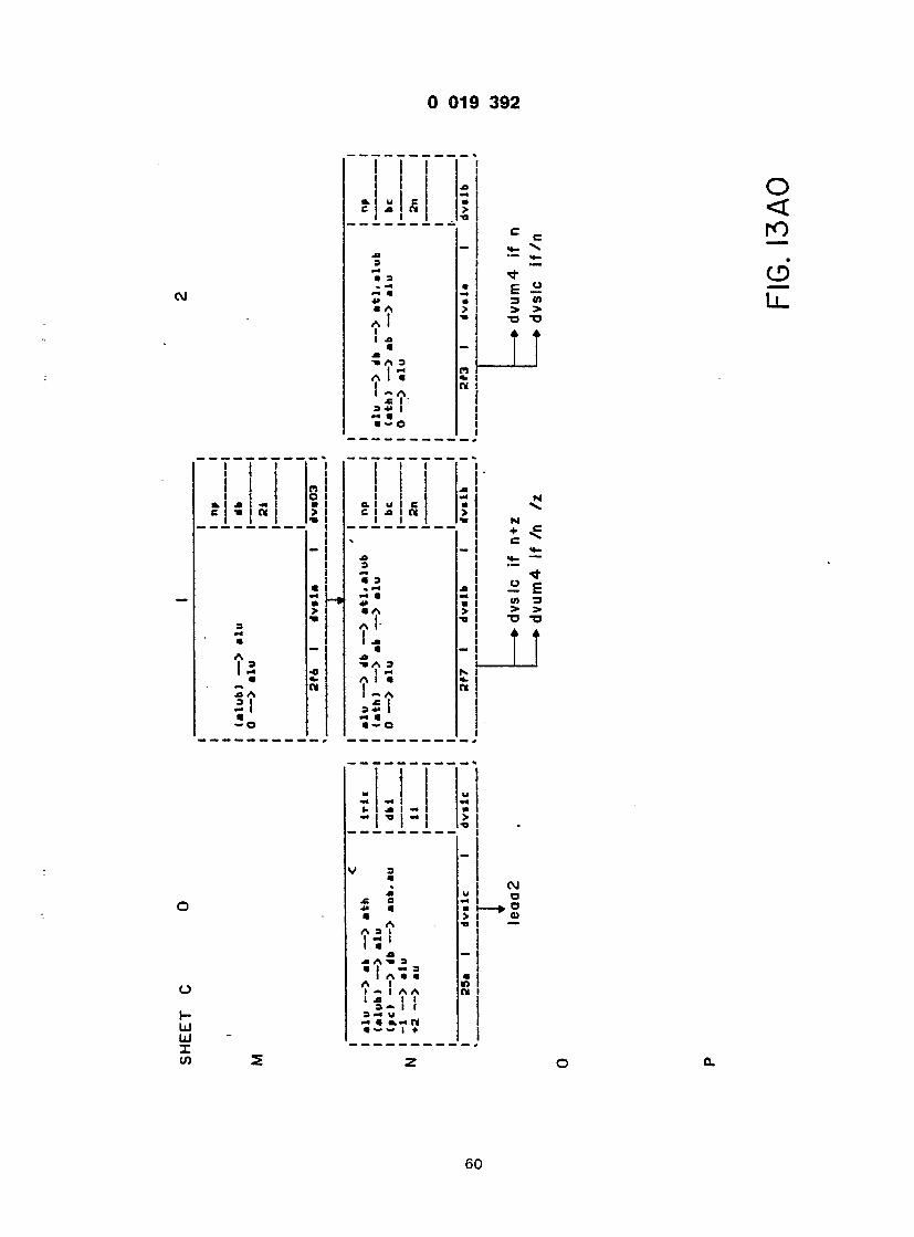
1 / 1
I I I I I i n i o I
11
i
c
> > •a "a A 4
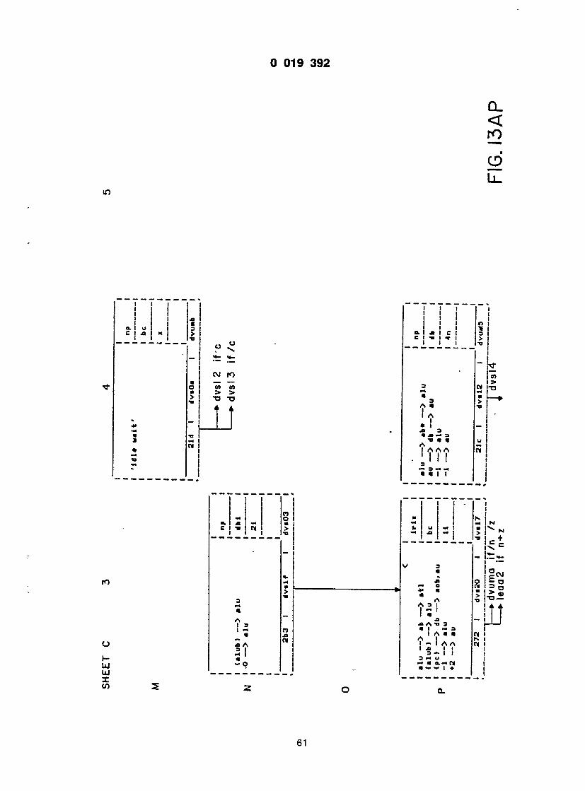
1 « r
c
L
* 4 A- , 1 A
_ 1 @f l * 1 - — 1 M 3 @ -a @ x» a a « -o @ @ u W A • 1 AAA n — 1 I 1 1 •n - i l l •m a *m a I I I 1

I
>
— @ — i i « o A xt I o I u A I xi A 3 @ I I • I 1 I I A u I
L
1 O l" Xi o I 1 u A a. 1 OA a. 1 I- | @ 1 9 1 t 1 • - i I I 1 xi - 1 A i

0 019 3 9 2
SHEET C 9
N ;
@u @— > db — > aob.au I trop ,4b — > dblnh • @2 — > au I db
19c 1 -Pi 12 1 *P*w2 @
O a 1 1 au — > db — > aob.au 1 trop 1 •db — > dblnl ••2 — > au @ •
ZB i ap iu i @f»«
J
mpil 4
au — J @ • — * aoa.au (dbin) — > ah —> n h •db — > dbinh ♦2 — > au
{rut
am
it* 1 mpil* I i p i » 4 mp iw3
F I G . I 3 A R
63

I @ @ @ I 1 - i »- i xi « « 1 « Ti i 1 XI
u
cm ! i XI f> k. 3 xi E
i . XI 3 Ti @ n t f
5
s n a +- 1
I I I 1 ! ! L - a. ! 1 1 1 fc 1 O I ft! x 1 @ u t- xi 1 C C l T i l M l f c TI — 1 « « l l l e . I
. _ 1 XI 3 1 V 3 H L pH a u a a •a 3 m| 9 — A a xi . i A xi r*> . I 1 1 A a xi 1 1 a o @a i a a xi a i xi @a xi XI 3 A « a Tf a — j A i A 3 u A A A 1 •* a, i 1 1 1 u a 1 a I I I u A - n A ~ A C - ~ N CI I — ti a I I -« i J « > . XI 3T t t.< 3 T •< a w i a w l

MM>«<MM>MajM*MM»*H>*MBM»<>m.*l I j
Ml I 9 X — i — I U 1 i. I xi — I 4> a* — I -o M j -o * I
: = I n > — — i *
A @ I O \ I (- I i_
I I I I ', I I - I
M | | Jl M| — 1 — 1 |3 ] I U I JJ — I @*> O* I
3 * — U I
a «- a a i * « I w xt . I J> . — • — @O JB A J JB !
TJ -» 4»
ro o u
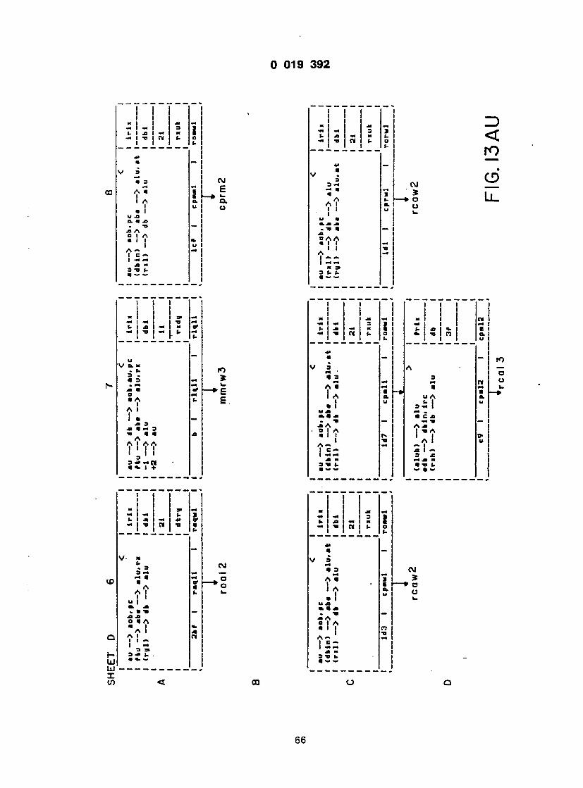
I i I
— i — 3 1 i "O W f- o I (. . i
IS l— » a I a. u j 0
_ I
i I Ml 3» M I (. I -a -< m «* I I TP (. >4 j
1=1

U U19 «55«
HEET D 9 V. 1 '
iu — > .ob. pe 1 Ifit 1 n l ) — > db — > alu 1- @] rul) — > aba — > "lu. at 1 dbi 1
1 1 1 21 1 1 1 1 nuk 1 t 1
ld9 1 cprail 1 rorwl 1
> 1 1 (ath) —> ab —> alu 1 frii 1 tdb — > dbin. ire I" » (rxh) — > db — > alu 1 db 1
1 3f 1
cb 1 cpr«2 1 epr«2 1 l
c a i o
V 1 @ au — > aob.pc 1 ir l i 1 (n l ) — > db — > alu 1 — -1 <rul) — > aba — > alu. at 1 dbi 1
1 1 1 21 1 1 1 1 nuk 1 1 1
Id" 1 eprll 1 rorwl 1
I cprl 2
F I G . I 3 A V
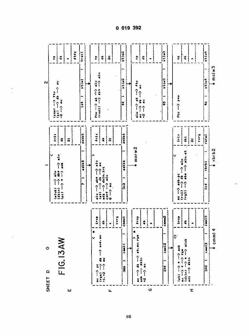
I M i
c ! ' i - I ' l i ! c ! . . .
3 1 .J J> j «, A\ — — @o Jl A A 3 I I I A @ , , i 5 II -a A * 1 A ** ** ! - 1 1 - a — i -o i @ U 3 « 1 a. a.n 4» (. 1
J
I I I 1 I I I 1 i i M l '
-I i j» x i i jj (. 1 X — 1 JJ 1. I J> 1 M 1 Jl 1 1 l a i l l ai 1
1 .-1
! � 3 A 1 m 1 a i n 3 jj A JJ J> _ M 3 JB 1 1 a j> t— * a a jj la a u a i a a a t- a i 3 * A 1 - 1 H JJ j I I . 1 a -a C 3 1 — * Jl M M — a A a ji ti .a a II a -a 1 1 A «•» A A 3 m 1 A 1 A 1 « u 1 t i l l ' n Ji C 1 I A 3 — «« i — Jl u 3 4> Jl (@ 1 i t a m a -a a i a a u o
n n
I 11 . 1 1 3 1 o. I jj m | a. jj 1 1 —I C 1 tj m -u 1 C t j | » I •» 1 1 a 1 I | • 1
n i "ci 3 3 1 3 1 4i m i— a. — i- •@3 4» 1 +> 1 a a 1 a 1 A 1 1 1 A 1 1 ' 1 • - i 3 - ! Jl l a 1 a ji 3 i d . 1 @a a t> 1 -ol A «r l a * i 1 A A I I 1 ' 1 ! . i 1 I 3 1 3 1 m 3 a i jj i a a + 1 a- 1
I I I i
M I I al I al I
1 1 u a i O.JB Jl 1 - tj a — l 0 A A a l l -a 1 1 u A m 1 — — | M M M 3> 3 t. U a ^

i i t T i 1
l » - I — T> I @ 3 I AA a * I I I - I
u js o. a jb . TJ JB A SI ?
I A *> \ £ n 3 TJ (. a — ~
r " T ~ T ~ i "
i t r ~ i i l l I I I I 3> — I I. I I t> a. I a I j I c I > o I C I "D t " "o jj I
_ i _ 1 _ i _ * 1
- I 00 I * I cn I l_ M I J» ' m @f m j a * i (- I A I I I I I
a I u a 3 | a. p-i s i a a mi A I I I I A I I i I 3 I I 3 JJ I a a. o l
r — i i i @ i i i i i w I I 3» — I — j m I «- a. I u I Ja — I « a I j l_ a I
5 - ! cm a i Cl V jJ I °
= 3 I S MM M I CO a a a, i a i — » A A « I I
u CXJX M I . t» a — I A 3 I 0 A A " I a l i a u i II * I
I 1 JS M | j i t t 7 |
— — — a> — • «@» aau — — • «• j» *@> a* OP*
I
3 B I a. a m jj I C TI M TJ a j 1 « I
- j I *
J" I *- a- m | oi A * I — * 3 1 a I a i @ i
A -a I i a i i — i A I ja I 3 I ti i a jb i -0 I A - A I I c I I I m | I ja I 3 V IH I a — I l
X
CM <D CO l_
-*>
CM a. o S (0 -a
<*
cn -♦
CM a. o S 10
cn — »
A 1 1 a u a 3 a. m f> a a a A 1 1 1 A 1 i 3 1 3 *> a a. o
1 I 1 I I I I I I I I

1 1 M j j J* M -< -« i is <- (- XI 1 M 1 — M — -a i m | i- s 1 1 C
XI • V S3 *• a a 2- @ - E
S V " i A -o -n I
s « at I !
i 7 ~ 7 ~ 7 ~ T " i i : : i i n i i ! c ' a, xi 1 a> 1 m | c , ] R | = j
o — • M @ 1
1—1 ' — 1 I . CO CO J ,T <-"-' 3 n E * 3
< r o
CS>
LL.
>-
o
• D

) 019 3 9 2
SHEET D 9 > I I
•db — > dbin. ire I rrii I (rxh ) — > db — > «lu I 1 (ruh) — > ab — > alu I db I
I 3t I
ca I epria I cprl2 I , '
ecu 3
H
alu — > dbd — > alu I np I (alub) — > alu I 1
I db I
I 2* I
a? I aulnS I mulmS I I m u l m 4
F I G . I 3 A Z
71

119 3 9 2
m\ ^ I A i a a A 3 ' I '
i -a i 3) 3 <- M « ~ I
. 2 Ll .
i in
• a. +* . a 3 . • 3 _ M « A I •» I I a x 3 a A a a I f\ I A A l~ ! i
3> s c. x n a " i +
@ 1 1 4 @—II J «. 1 i 1 n i i
u AA t. I I x I I . e s • A X X a -a jb a a -o A A3
34>JB f. I x a -a o a — a u O
*
i i i i i *• i
: I s I
a
*» « j i « « a s A A a A I I I I I A - a »• w mm a.M
- I S !
- X - A @a | 0 | a * A A 1 *
A 3 A I X 3 •a I a a A-~ A A I e I i I x 1 I 3 H X « a- I ♦
m X t> JB X x -a W i
1 J
" 1
UJ UJ X CO
1
a ji o A a ' t a i .a - a e a s x ti a A JB 3 I Ti A x A ' aI • ! - I A C I - I N x a I ♦ Jl JB K Ti Ti I. X X - a*» l +
-j * m -A JB I O I
I - A Jl JB I Ti 3 Ti I « . A A - I A 1 x | JB JB 3 Ti Ti « a — a ♦
n i x 1 x • a . 3 A x AO a a I a M I A «• A
t AS I I Ti @a I jb A A Ti a jb l s a I A a
* A ~ i A 3 <a u x a ti a. ft a a — — ♦
1 1 *0 | •-4 I f u
a-1 | u
N «f n
i i i
a A I u k 3 Ti X x A • a Ti c Ti x (. A A JB x
1 I A A I - - I I a a I 3 3 — X X Jl t- a a Ti x
/ii
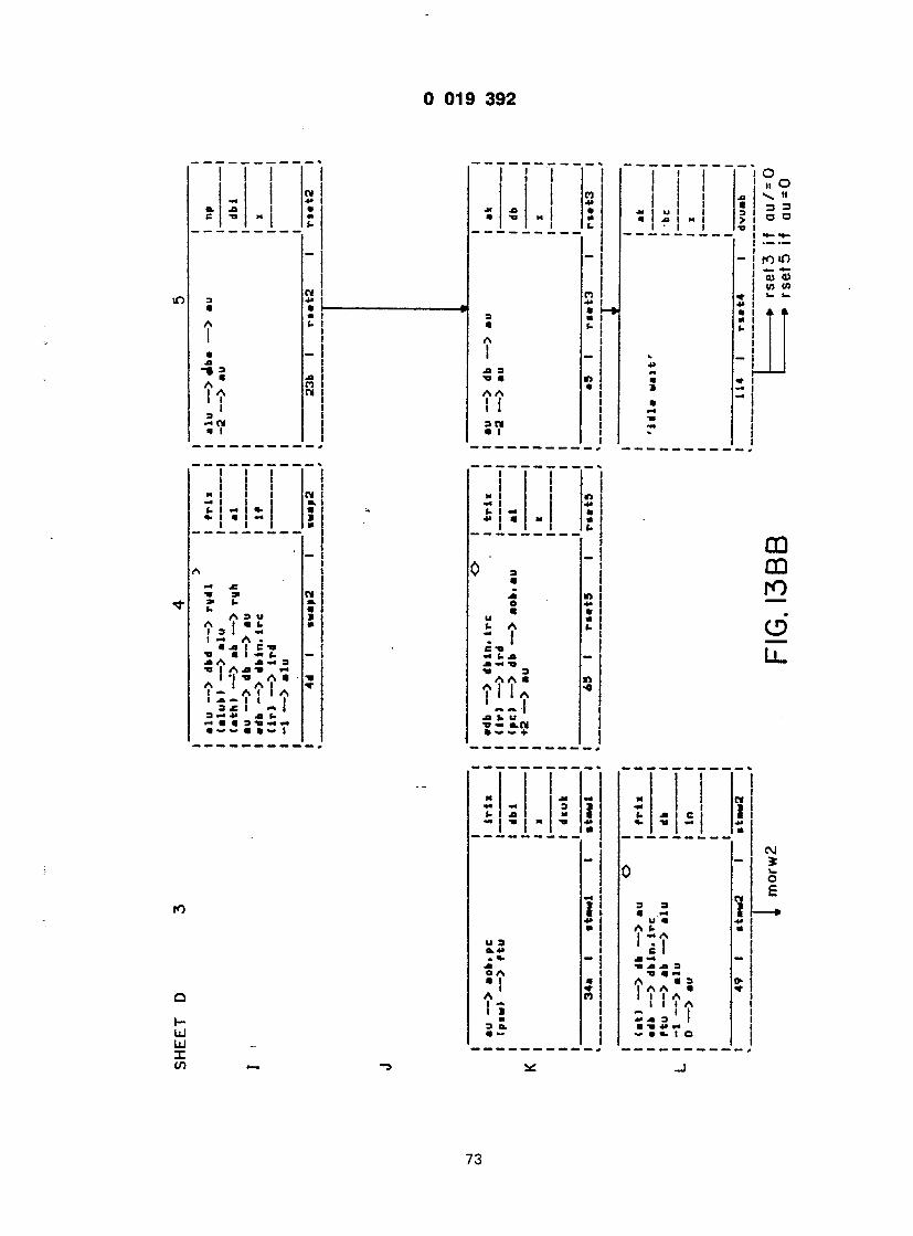

I

,EET D 9
i
i
@ @ •rap — > r tu 1 nP j
1 dbc 1
1 i t
0 1 r«tpl 1 r»tpl 1 " A
• to — > dba — > au 1 np [ Cinl) — > p»m ' J — > au 1 @@
1 i 1
23c I r»tp2 1 ratp2 1 . . . j
O i l au — > db — > aob.au 1 t r l i 1 (dbin) — > ab — > «ph 1 — — J adb — > dbin J d* | +2 — > au 1" '
1 « @
2bS 1 r»tp3 1 r»tp3 1 .
' ' r s t p 4
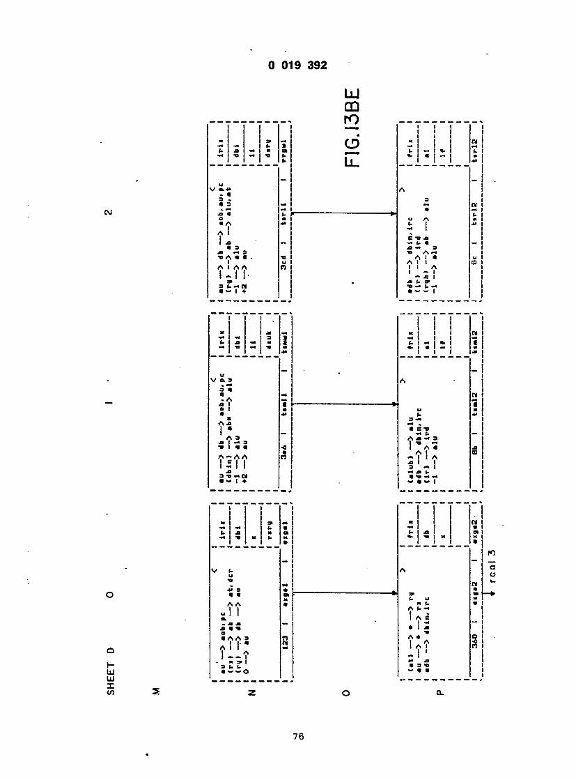
S A i l 3 (- «. (1
a-o — rii @ — i +
1
1 1
*> 1 1 1 1 i
I s
1 "
j - *

L c
r
c @
1 - • 1 I -
I I I — I - i
I I I I I

- — I. I I f- ja <** « t- I •h t» n u c j |C!
@Jt @ c I
A * I I JB I la - I jb A a a I •a I — a -0 I
I I
2
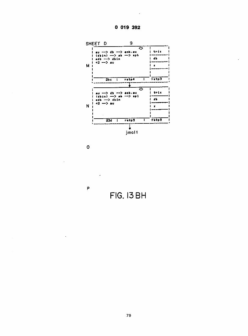
t 019 3 9 2
i H E E T D
u — j gg — s foni iu dbin) — > ab — > apt* db — > dbin 2 — > au
•«t —s au
r i i
2b c I r«tp4 I raepa i
O I I au — > db — > aob.au I t r i i I (dbin) — > ab — > apl I — • adb — > dbin I db I
MO i ra^pa @ "*p>. 1
jmaM
F I G . I 3 B H
/ a

0 019 3 9 2
CNJ
I I 1 1 1 I 1 1 1 1 1 1 I I I @mi — i 1 o 1 ol-> 31 a. xt a. a <- 1 • 3 -a a 1 -a @> C tj @ • • 4> 1 i x a 4 > - e M a +• i -o « a l -» I ~» -i | -• 1
, * 1
0 Ot 0 i *» > 1 a 3 -a xt 1 Q x 3 -< a o n a n i A I o • 1 . 1 1 3 TJ SI I a —» a a I— • x a !_>. a a k- 1 < r A a OA a A • 1 -» a I -» a I -• a i -» i 2 1 ' a ' 1 '• ! a x I x xi i — xi u tj — la — x i a — i A a (@ tj xi i 1 u — A 3 Xi A 3 0A3 1 1 o> a a. i a o> -o i a a a a I a x I a 1 A 1 N 1 N i l N I - n I A I A tt A A C* 1 A A W - ~ l ' a l l : l - i s ! ! JJ 4> JJ) M U 4J U 1 tj a 3 -a (@ a- 3 a.nj a 3 a.N 1 » ~- a a -» l a •«» + ~ a •>» + 1 t i l l
D. I X I C 1 TJ i I I
3 a a I A I a t * a A I A I I I C *»
- I • I
. 3 x a o a a
Jl 3 aA a i
u 3 a.N a — +
i i _ i - i • I @» I
— i I
— i @ u — A 3 *• t m
-7 a- "C m • — I
3
CM a M U J
r o
L l .
i ji I TI I
UJ r- UJ UJ X m
3 4* a a x A 0 I a i A JB 1 a c I -H A Jl Jl I TI
9 TJ a
Jl I TI 3 tj i a A A " I A I C I I I - I XI XI 3 TJ TJ rn a — a ♦
I
I I a A I I
x « « Tf U TJ A (@ A u I —A 3 I 0,1 A I "
A — I A «@« I C I — I x I — a I 4« X X » 1 3 1 1 b * — a — • — i
m
80

i o. -a c t
, o t a. 1 I a. m I • — I a l
2 ! U I a I ~7 |
I I I I I I I I - I ' . ! I r !
1- ! x x
i i i
a, xi >. a |
k - O
CQ r O
CD
L u I
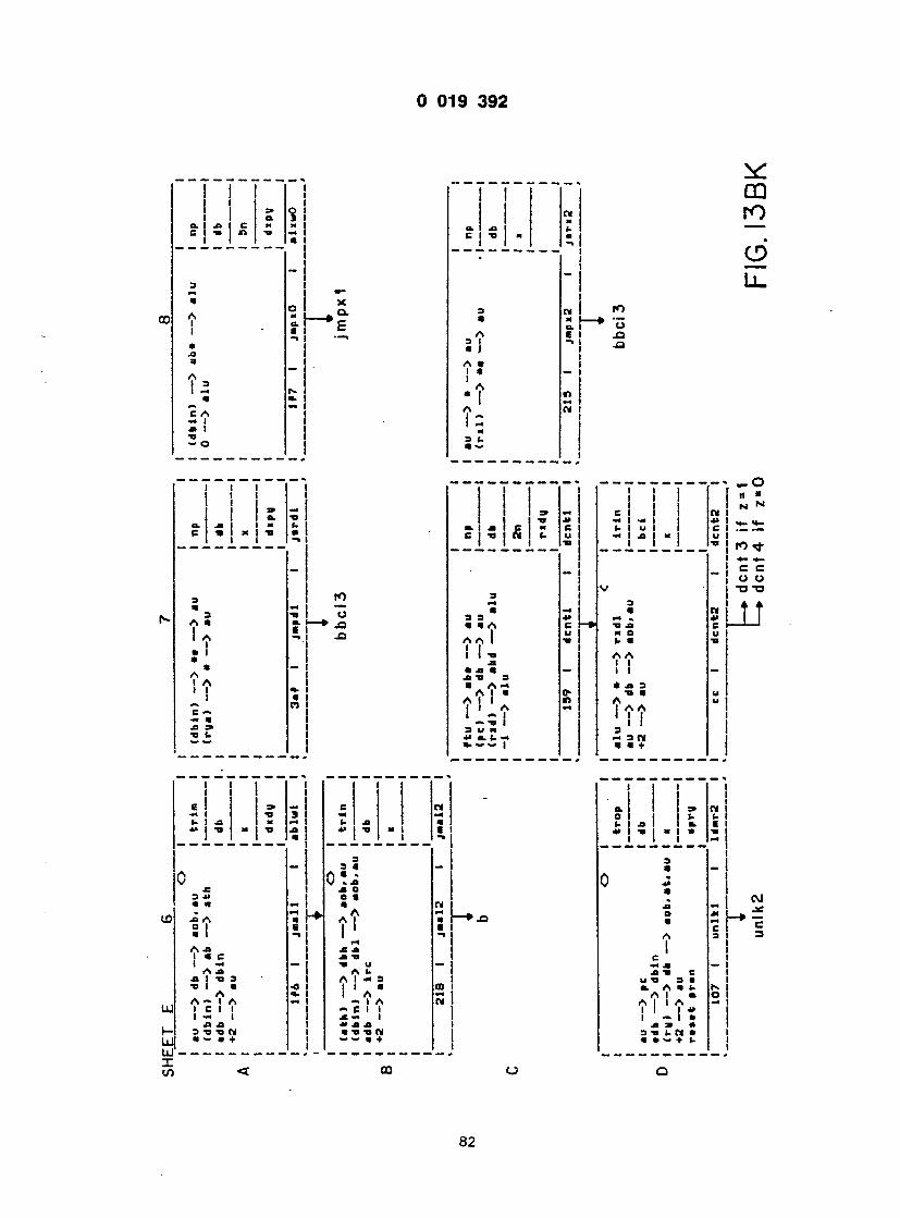
! : ? ! O. J3 I C — — I c -a I n -a -* i
' =1 I 3 A " 1
i - «i =
A I
J J
3 «, •< — » 3 TJ O r- A « a. I •> _o I A 5. * 1 • I » * — A
i V * 1
» i
: i
M M I L !
! 5
!
i

1 t t l t
ya) — > • — > au
jmpxo it ire ii u - i j m p x 2 if i rc[ l l ]= 0
ri) — > * — •> b
bbci 3
j
- I G . I 3 B L

O I
&! Ill » u I c I - I - I * 115 1
i
as u i> I ja
I JQ
c n i Ml Ml U \ J» u 1 4> i -a m xi 1 1 1 XI 1
« .
" i 3 1 @ n i xi u | — k> -Q • O U XI j

-* 1 u a t- 1 -o " a. |
0 3 i
0 m 1 A E 1 1 ~> 1 1 1 1 J> I u -o — I
— A 3 I I a tj 1 A 1 o 1 1 A 1 ' .1 i XI =» 1
!
j } j 1 1
1 tj j e I i U a. I xi c a. t- l 3 -a i (. C tj — m m 4J -a m a ' 1 Xi 1 1 JJ
~ i A « ~ j V fc i '
ml ai 57 "J 3 i. t-«> jj " *i i * ? - 1 @ - t :
ol 1 1 ! ! ° =» O C I I - 1 11 o. 3 1 — I I 3 | , — J. J J 4 Z O . M I i. u | ~| — : @= r> a - i — xt » i •* , 3
j ! t-
» ! v ! .t: * i j O 1 _ 1 CM " r* 3 @ a I n • • i i : a. A a. 1
; ! A i ! a - i ' a - I t
» a xi i 3 1 * O A 1 i "2 "* "1 • I — @ a. 1 A I CM 1 ' — 1 1 A —1 :a t — i • i la i 1 1 a a» l _ 1 M 3 I. 1 o j a a — i
@ i i i i i I
1 " i
0 2 = „ fO C
- n t • » o L I xi 1 r-
- ! l c
o xt a a
M i -
i
—i j
) C 3 > 3.

I 019 3 9 2
i. | @«
(~ (- @a*j
• -a A A I I I I 3 X m Ti
i
i i • i > i
. _ ! _
«» 3 3
3 @ • • . A A a I I 0 I I @ TI * \ ja 1 tj @ I A A a l l s B i l l A, — — A I I I TJ TJ i » a> s «- «-« a — — I
L. Jl
«J# (. A ~ I e tj — u x X -H TJ TJ 3 A A a
X «. U t> -i O.TM a — — ♦
1 1 1 1
a — i a u i ji u - | ,
u V a. * .3 n a j* . C 1— • x u 0 tj a A 1 Jl 3 n tj a
8 f t 3 « a + -
i O
« s r o
LL.
Ill
j • j 1- a. I - » « " * Ol « X — J» — J" (. 1 X M ( . J i t — (- — «-> JJ 1 TJ m JJ — t j m | C *@ a h C l a i s s
0 V 3 A •* £ • £ 3> 3 JJ - _ 31 IV a a r»: ja n i. -r J* l_- O x A -» jia M l - » a (-♦> A i - 0 1 c « C 1 o c a 1 3 (. A 3 | ( - 3 Ax A 1 X X t 1 a e i x a e -a 1 — — ix — a» j» . —
Ax TJ A X -M A. 1 Ti 3 X 3 A I Ti tj I a a • 0 a 2 j I 0 • A «- 1 O i A CD A ~ 1 A A 1 A — I 1
\ V \ !~ l x - 1 - XX U X X X (- 3 tj tj (M 3o.r») a TJ TJ — a — a + a ~ + *.«»a —
Lo UJ u- » J-

u u i y j » 4
HEET E 9
J J gg —J aOB. au rv-> — > "b — > alu. a t 1 — > alu 2 — > au
i r i n
l inkl 296 1 iin*l I " n n i =
. ,
db — > ire r*a> — > db — > au 4 — > au
NaW I * ii mm ~ r ~ "
# - • —
@ ini — � a» — iu — > db — > aob.au. rya •2 — > au
Bf 1 l»n«il 1 i>.n«j i
— i - ^ - , , I1U , -' "OB iu --> aob [dbin) — > — > au Irga) — > * — > au
• — — r
F I G . 1 3 B P

9 019 3 9 2
CVJ
1
X 9 — @m — u r n (.XI x a TI - U •
( 3 4* »@ *» «« A * " I -* I A • 1 II • — j
U XI 1 a. a xi -a — xi A 0 1 A _ . I | PI A -» 1 c — 1 — a XI 3> a ti u a ~ —
»• u A 1. C TI . XI -« t- XI a xi — -a @a 3 A A A a
1 A I I A 4» XI (. U a ti — a. cm
o CD r o
CD
L l .
r i o I I
c I o. -t j a I
u r\ n (@ I I — I I u . a. C xi xi a -a f\ r> xt 3 a l l a a A ' A A i ' a a I I
xi x a> 3 TI (. (- — * a a — — I l
w x a CD CL
i
3 <- @ . A JB I a l a A xi
I * u A U ja I — 3 ti i a A A — I A I e I I I - i Xt JB 3 TI TI « a - » +
rv I I a A I I
A U I -x A 3 I I a A I x a i
3 T T k T a a — l
o a a.
* 1
UJ I- UJ UJ • X cn
3 X m i 2 A a I A J» I a e I - A ja x I -a 3 -a I a A A — I A 15 ' |
@a xi 3 ti ti nl a <- a +
3 X a (. JB A 0 I u a i (@ A J> - t a e 1 —
a -> ! e
a a
3 TI TI CM a - a +
lo i
I a 3
JC 3 J> a a JB A SJ A JB I a c I — A J3 Xt I TI 3 @a I a A A — I A I c I I I - I xt xt 3 TJ TI CM a — a ♦
88

-I I
!
d - j
* L l v - 1
x n i o » 1 m a @ r ~ u m • l Qv a (. —I • — A 1 .A C 1 1 1 M — I
I I,

_ — — — .
@ u u _ o
A x 3 T T 1 -o « «. N A N - A 1 AA- — 3 1 i t •* X - @ @ 1 +
1 H | X «4- - 1 — 3 * « I 1 CI (- x 1 u
3 a @ —
V " 3 3 3 a a CVJ . a a @ XII x 1 — » e 1 i x -C a u cj a -a A x x 1 "
A A 3 1 1 a A «@> «» A •» 1 e-< i 1 - -a 1 X V 3 -a b « @ . a v i
r ~ 7 "
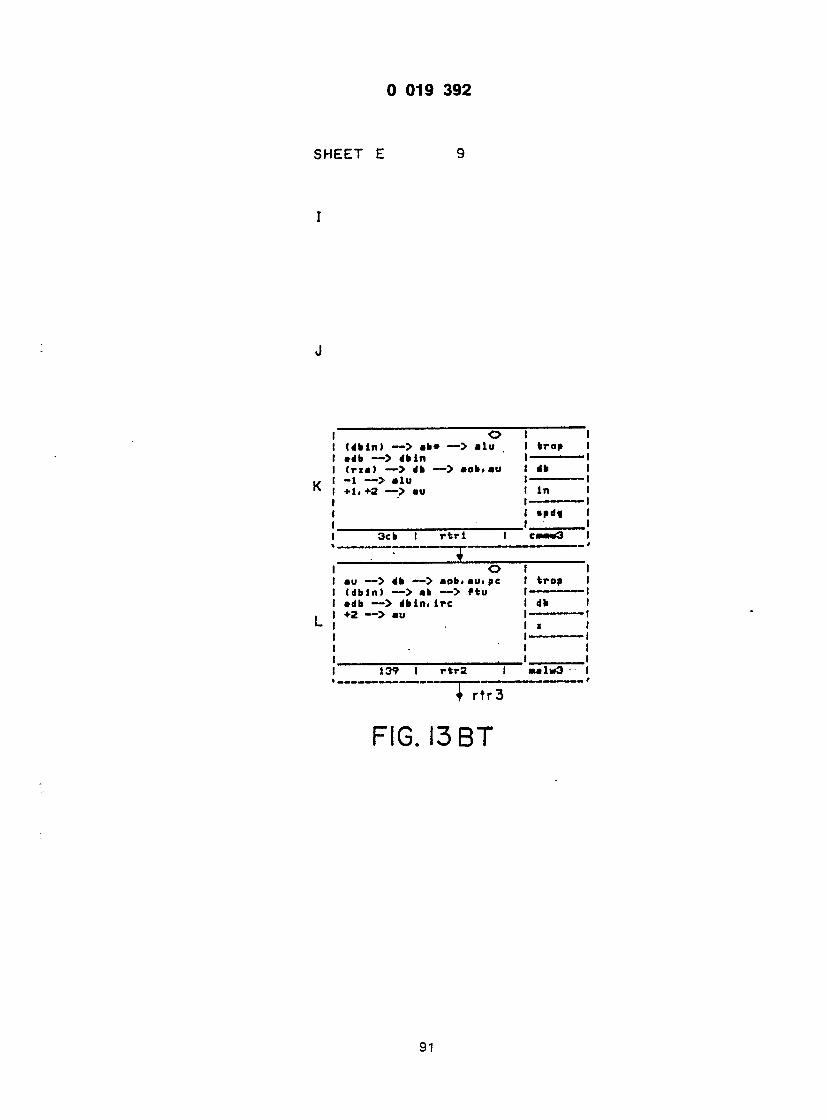
3 019 3 9 2
SHEET E
o (dbin) — > ab» — > alu •db — •> dbin (rit) — > db — > aob.au -1 — > alu @ft. +2 — > au
I crop I I •• I t In I I Md« I . 3c b 1 r t r l 1 caM«<3 1
o au — > db — > aob.au. pc (dbin) — > ab — > f tu •db — > dbin. i re +2 — > au
\ r t r 3
F I G . 13 B T
139 I rtr2 I aalwa
91

I
r
(

L a. xi a ] Ci~ " I J5 |
~ - | ! i 1
«r i a . r - > . o x a l
a! i i i 1 XI - 1 @o I XI 3 j a A a n 1 -0 a i a n 1 U l !
u 1 S^T 1
i
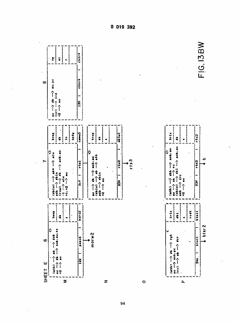
3 019 3 9 2
A I -a I (- X 3 •» A « I A I A i - l
(- 3 — W • »» ♦
I !
LU r o
e >
L l
@@l-l I I
>@> 3 V 3 @ « XI o t ; . i XI * ex 3 — ti @ Ax 3 I -o A — A I I @ I A I I — I A C I -> I « — @ I + X X @ . — @ — 7 +
PI i u
•
— « — X u
•> u PI
I I X x I -o
3 X @ @ X A 9 Ax I ' 5 - ? ' = > @at. @ A A— I A ! s I ! 3 Ti Ti W @ «» • +
ID M
1 \ ~
mi
e @ A
x A X X I Ti Ti i U A «- "A X I — 3 I « I • I A A — I A — I C I I X I — I 4» XX • 3 Ti TI tit
CD
UJ
UJ UJ X cn
X 3 O «j A O I @
A x I « I Ax 3 I
A A
I 3 N
CM i O E
I M 4» *•) (- xfJ) M «
•a
I I
X « A O 1
@ 0 @> W ffj W
CM w 0> J3
94

H E E J E 9 _
I i
I
O 1 I au — > db — > aob.au 1 Iroa 1 <dbin> — > aba — > at 1 1 ♦2 — > au 1 db 1
1 i 1
3a5 1 rtr3 1 aavaw2 1
> . 1 1 au — > • — > ri • rroa 1 (dbin) — > • — > ath 1 -1 adb — > dbin 1 db 1 ftu — > •«@> I "'
1 i 1
40 1 rtr4 1 r\r4 1 1
ma i z
3
F I G . I 3 B X

i~ T I
» =» — M — I T> | I — — -a ct \ -n u I ti a*
> @
4« -V 0 I @ XI 4> j TJ *. — JB A o I AA • i l l O I i r» I A= — " I
i a A
*@ - - @£ - I T Ja @ ti j @ A A a . «. I f\
I I I M a A
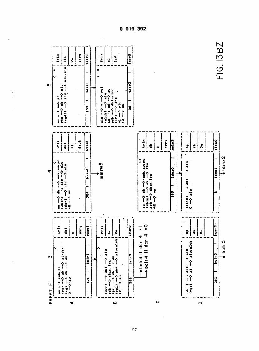
* " - I • I - I Ja Ja A A * i 3 0 a I a i -jb ti — a a i n in a a a A « a A I A I -» — I — A I I AA 1 ' ? ' S t L | |
a » a — x t. a j* ». « i a i « « N a*— a a a — i + .
! @M -J I
m I x a t @4 1 1 -U I
( a jb i i -o - j
I I i 1 I
C i a* F) I - la. 1 U jb a. —I a. J* -B X j U J j C I
| I
! ! o x i =@ — x 1 « . — I-- t- u — «- 1 (- n ( . . x E - X I t - — — @ 1 M - o m - n a », a m 1 a — 1 @*> 1 •»
• - * c a — — _ «
V a 1 A | a 1 U
_ M| « lO 3 A t- 1 <- m I a f— • m a
I I I c !
i t * i L T i

) 019 3 9 2
co
0.-0 XI xi a a a i Ax • , j • = A — A
« 9 I a b b x • - — I O
X > b @
X a i b a
8 n
i i i i
a a u i a a b I x * I A .xi
, | x ' xi xi a a u i I x a a ' a 1 V I A I - A A x >>y\
, 1 1 X 3 TI b X X
o M ( V. 3 a
3 N 3 O
ro to
« c
u
@ 3 A 0 1 I A • I xi a a xi x a "a • a A I A A A l i l t I I I a x a x x a a I I
2 ° o *• " - a v. a
3 3 O O
lOlO
<t-a to c
It t
CM I l
aA a
1 A
@a A xi Al ' =
c i a #X 3 I
x a, o
a x a A a
O XI A Ti 3 TI O I X 3 a I A a a t t i i t t . a a u x 3 i a>x CM a a >- «@» i +
< o r o
LL.
CD
UJ X cn
4> 3 a a A A
o a A A 3 I 1 • A I I ) A 1 x~ I » 5» I 3 b b a «- ~ o
s x b a xi ai 3 » •
X b U 4> 1 XI
r» CM X
b A I -.1 «. e xi x xi a xi -a 3 Ti A x 3 A I a a a 1 II xk. xV 0 0 XI u w Ti a. b x tM a — — I ♦
— O ii n
<— I r— i
^ TJ
ro * u. k. to « «- U
* t
x a a x a A I A ' I a Xi Ti XI a k i x A A I 0
U b 9> ai x b
at I
m
98

0 019 3 9 2
SHEET F
au — > aob. »c I i r ix •to — > db* — > au I <ruh> — > ab — > alu I dbi -1 — > alu I 0 —@> au I In
I I dlfU I
I 309 I arl l l I . t r iai i j
srrl 2
B .
au — > aobt ac <r»dl) — > dba — > au (rgh) — > ab — > alu -1 — > alu 0 — > au
I I I r ix I I dbi I I In I I r i r g
306 1 arrll 1 arrwl 1 I — '
alu — > dbd — > alua. au — > db — > au adb — > dbin. i re <rudl) — > ab« — > alu -1 — > alu -1 — > au '
307 I • r r i z
f r i i
be
l l
arrow
-••srrl 3 if au /= 0 -♦srr l 4 if au = 0
F I G . I 3 C B
99

i 4T ? £ <i S- x a x <- x @ 4 < - « » ( . « - x - o _ i
• !
,u - - i . 'a I V .3 | 4> 3 X 1 3 - @ «- — 1 a cn > 1 .A XI
«. x x @ ~ - — .
@ i » x j 1 1 - i 5 1 «. X I -m m U X I c A -i _ _ .
I ! c l n i I ! . _ _ — —
I V 3 X
1 3 X 1 £ > » 34» @ @ 1 Z. @ @> 4*. x. u M 1 a
r * • -> S i - s l ; f c l U O U 4» ^ 3 1 4> 1 W
i : » a xi* a5 I
S i a. Ax A 1 • O • x -a 3 x I 3 3 1 @s 1 1 A £ @ • l a a -o 1 x - ^ l ' i t ! f " l ?
'21 1 ! ; " 2 3 1 -b * 3-» « i @ a~a + a ~ O 1 j
' 1 1 @ a> n @ x e n 1 x Tl 1 x 1 X X 1 b X > B. X ( . X . X ( . X 41 • 1 > k ) X Ti W 4 x @« @ @ j i @ a a j
1 fO Oa, 0 V j H
.3 x x j ^ 3 X 3 X 3 X 1 C 'aa> x aa r» aa n 1 M • . X . X fc . X | xA 5 r» x A a r*> xA « »— »» o i u f o i o i s i a i t . m a i a a 1 • j A X t Ax Ax I l a c j a c ; a f x — 1 x — I — 1 Ax Ax A [ X 1 -a 3 X 1 3 XI3 } a @> « j i a O « 1 i n i A a A n <o Axl.lN x A - I A « A x A 1 I x ' l i x ' l } x |
XX XX X I 3 •» •an N s u n ) 3 i N a — * + a — a + a >» + j w U. O X
100

f ~ 7 ~ 7 r
X -a h b • x @
)a 0 .3 • » 3 X 3 b •J «. — M T4
x a j r* xi J a l u i a l i • lb x J • •* — 1 @ Ax . A x 1 • C 1 •
-. - O b u @ JL JL — X " x (-— ' r—i • ~
o o _ WW.
•3 @ « ! 5 5
i ^ A I L A*l S
,1 t x
T T l
i'

1 @a / @ I
I I I ! I I
I - i a> m @- f >- U * U I m j C a x
i a
a. j> - • a — m m a o @» A — a I a a «@ 0 I @ S
i
a
VI 3 I 3 (1 I T I b i m l I • I
T M @a
..T a a
Ml c a « a
T I f " T *

0 019 3 9 2
SHEET F
nber3 au-0 alu — > ab* — > alu au — > 4m — > au -I — > alu -1 — > au
na be
41
2*8 I arrla I arrtaS
srrl 3 if au / = 0
srrl 4 if au * 0
< • i
H
au — > 4m — > aob> au> ic (•bin) — > aba — > alu -1 — > alu +2 — > au
I I r l i I I 4ml I
11 j I dxuk
.1 3«a I i r t a t ttaail
I s f t m 2
F I G . 13 C F
103

; ui S T I * % S L. In n -
I A I 01
* I @* 1 - 1 Is " - — — - - . I l__J I j u J I I
4. *
I I I I I
cn to
, « I— I H
I @5 i t= | mm »• VJ
"I I , ! I
! %
j « E » - i l U u I « r

I I 1
i f. ^ u I » Jl » tt C m ai C TJ ^ « C I * ^ to
** 1 1
i. a « f- pj i 1 1—
I I " i l l ""j 3 » L I u I @ k | M M I T> -TJ . i i " C t-
I -
- i ro
» , * ro 5 W E E E
— i_ c — 32 E _?
" i t t T
1 ^ _ — — — — _ c >
) 3 4» U a . A
- J j J
o a
j ! I i 1 <M I I —I : l x I Ml t. I o M j « | 4< I Mi
U
M JJ M V> k- n at. r> 3 u t. 1 ' - > « j»a @ >= j 1 3 . 5 1 2 | a A js ~ " •S - i - f 1 % M A Jl C 1 @» a ji t -a 3 • 1 • cp -j f aw n A * A n . n
J >

1 1 1 c ai m a. r* x I u i o x (. (- 1 x a. x i. u I X J Ti M u , | X X »• Tl
a 5 i 0
* - a a ax . @ *@ x X M @ o @ x A o. a a. 0 j u a o
x *" A a. A X t 1 1 X — MA —
w 1 a o 1 U @ a I x a i l . x X A jb A x . 1 a e _.. i « c 1 x — | X — Ax Ax x i -a a x | ti a •a i a J -a I a *> T a ' t
8 t s * t S
XX XX a TI TI W 3TVN a — a +
@ i * @ @
M
A A I I I I X X a -a a A A a 1 i A
' +

) 019 3 9 2
SHEET F
@iu — > ••• — > 11U (at) — > da — > au @db — > dbin. Ire -1 — > alu 0 — > au
•1 I ITXBM
> • I
morw 2
rr ix
I db
I 41
au — @> «• — -> aoa.au (dbin) — > ab — •> f t u ♦2 --•> au
K
3a5 I auani
au - — > ic •db — > i re <rna) — -> db — > a t . au -2 — > au ra*«t ar*n
29r l pu«n3
i a r m I I aa
I x
i r»T" I axarri
r r t n
@ c
I puan.*: j u s h j if endr h4 if , * / e n d
l. c :x ... / . _ j pushD if w * / e n d
F I G . I 3 C J
107

o f - II
(. u c » u I o — Jl X TI u I CJ
A Jl 1 @ I - A Jl I 3 • i M
l_ I
-1 c @= C I » -a c 4* I *>«. ~ m
u A A (. ! I -
c
) J 3

• n o - L
- r r r o — — j -o ja o *> — (. u C I « u jj <J
_ _ _ _ _ _ i Z _ - - . t : CD * _ cm i*> r—
-o LL. v „ 8 8 U T» CO (0
A xi I i ;
I f i c xi •>• a ja a — X TI 3 X TJ A m* 3 « l A a a a. r» A l l w
j 1 AAA Ji u a. TJ a * « N « a — — i i +
T T i l ! " 1 ! ! T 1
— — I t» ja j o *> (. u C I « u I 0 o _ — a 1 H_ h-
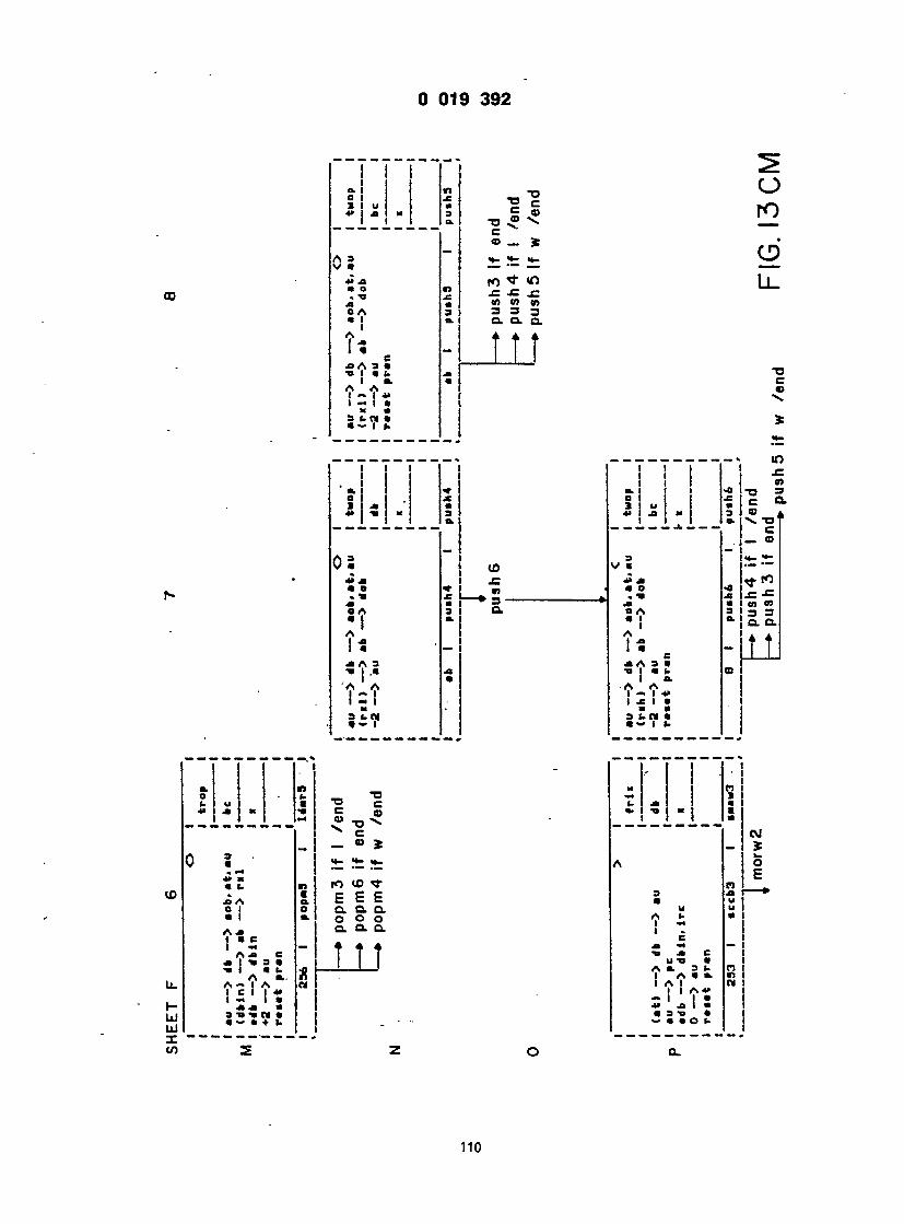
a. i n I 0 1 x 1 I u mi X X X 3 1 I I a. 1 — 1
A3 | V • I XX j mo n 1 - TJ jz I x • i OA 3 )
1 u
e X A 3 • TJ I @ C I @>
T t r
I I I I I I a. | | S ! .. I
A \m X A 3 ' I - *
i - 1 H SUM I
I A I . C X A 3 • TJ I »J (.
I -
! i
I I I I

0 019 3 9 2
SHEET F 9
O I I (at) ab — > ry I i r l i I (@c) — > fir — > aob.au I 1 ♦2 — > aw I obi I
I » I
2b I auah3 I poaavA I . , »
nrtmrwo
0
P '
F I G . I 3 C N


- 1 - T l

U - L
o
r r
r
— —
I
f a-
r
r
r n
r
t -
1

1 L_l •=>o I 1 \
8 L ! o z < z
«
J 0 u
» r
3 *
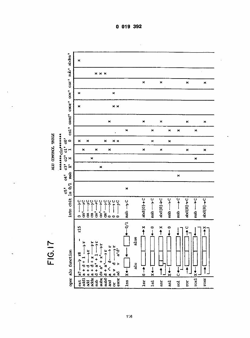
I
X X X X
X X X X X
X X
X X X X
X
X
X
O U U C J U U O C J
j j r
1 1 1
1 1
j
1-1 0 X O X O i - | U i—i X-, J t I t i 11 t-l J t
□ i n n n n n n n n
1
n = u u t L U U U U u
T 3 t i t I I
J t J I t X O X 1 x CJ X -1
CO t l r H t l p H r H > j ' x ^ .3 n j n s e s s
116
ill *
o "u X X 8
Ii g X X! o
s * _
X
T -
X
X
u

_3_ £h - F-j ffl
O «@ - W Q C5 Qca « cj o* u o a: _ «. co o> J c d s m c_ u Q5 u — <0 U Z U 2 2 C Q J u Z £ U CO O p * * " . . * CQ M > M » J M M m Z J E - l Q X J M * E H M O o c f l Q m > n . D x o c a x « •> Eh CJ Q DQ < Z DO S S t a f f l D O Q M CO 3 <J «C COST U CO CO 05 _1 05 IH 05 » - - » Q E-ico . - Q - •> » co 05 •. - x - » CO > Q 05 CJ Q CD 05 O j i J X i J 0 5 E h Q o 5 - c o 2 i-h QCO CO 2 DCO £ D O O O O Q O Q 5 < H Q << < < CO J U X 0 5 Q 5 0 5 Z < U O E h
Eh tH t H I H f H t H t H k H t H t H ^ « t H ^ i t H m x x X X X x x x x x x x x x Iil U W £_ H W _ l C _ C _ H £ a c _ C _ t a CO J ca @ — — - — — < Eh
< <s < < ta ea. ea. < *; ea. D ta, > ta. ea. n n ea. ea. n O N N N N Z Z N N 2 CJ 2 2 2 2 2 «C Z Z 2 x < < @< < E t_ -x. 2 — «S 05 05 J Q J O < 05 J J 05 X X -3 05 X 05 ___ @h J CO CO CO co O O Q Q O O Eh C 0 < < J J 0 5 0 5 0 5 0 5 0 5 W
q CD 2 — — 2Z. o u * LL. Q U *y |y |y 'o iu IU u 2 > a ea, > > c j n > > > ea. «5 n n 5a. n n > a N N N e a . c s . 2 Q N 2 2 n * Z Z Z n cs, Z CI U * Z lU -5 Z IU IU E U Z K O U i_ 2 2 2 m x x x x — x ca. x Eh 03 Q Q Q f f l CD Q Q CO CO Q 05 CJ D Q Q Z D o Q q d o q q d e ; 2 co < < «c cn co < «c cn to < w o b S3 Q ICJ ICJ ICJ CJ J |U U D H IU IU IU CH > > > > H < ea > Q ts, > > > t a . N N N N B a , e a , N N Q N N N N N 2 Z 2 Z N t a . Z Z U Z . Z 2 Z Z l U l u S 2 u 2 N
cn t_ u :_ lu t*s 2 t_ 2 z - x x x ea. x « CD Q O Q CD C Q f f i t H c a m c O Q Q 5 D Q Q 2 D D D X D D D Q O 0 5 0 5 05 CO < < < CO C O C O C d C O C O C O < C d O O Cd Eh U , _ _____ < 05 [_ < 2 t_ -S S_ _ 5 _ 5 _ 5 _ 5 C - Z M _s _s us _s c_ as u u u N N N N N N N N U < > 2 2 2 2 2 2 2 2 Z U J N > _; -s _s i_ t_ E _: E <c < z
_: Eh w X 3: — — — r- _ _ _ _ U - CJ CO z c_ a, ea, ca. ea.e_.ea. e a . e a e a . e a . e a . e a . t _ t _ e a . o O f - " U — ea. is, ea.c_.e_, t_, _ ta. ea. ta. ea. s_ k ea z Q cn os N N N N N N N N N N N N N N Cd Z Z Z Z Z Z Z Z Z Z Z t_ _S 2 Q " tc a: t _ t _ t _ s_ s_ t_ 2 s- s_ s_ i_ cc @» _: a < o u Q Q Q D Q Q Q Q Q Q D Q Q Q D Z 2 Z Z Z Z 2 2 2 2 Z 2 Z 2 2 < < < 2 < < < < < < < < < < <
o — cn m — r m
117
X X X X CO Q Q Q 03 CD D Q Q Z D D CO < < «C CO CO
Q |u u q ea lu i u

r <o> ^ tt — * tp — ' tt "tr ^ 1HH r-i — r-i r-t _-| rH rH
rH r-i-H r H r H - r H - H . r H r H r H Ul 1 jj cn cn cn cn cn <N cm cn cn ~| r-i rH —) -HrH— r H < H l H -H rH rH rH *H rH _ rH rH rH rH rH J- r-( -Hi-I ( - l - H — r - l r - l r H rH rH •H O O O O O O O O O O O rH r-i r-i r-i r-i ~- r-i r-i rH rH rH q a\ o\ a\ o\ a\ o\ di o\ o\ a\ a\ a\
oo as ao co oo rt-co co co co fj ) r« r> r- r> p* r» r~ r> ™~™ vo vovo vovsinvovo vovovcvo * in m m in uiin j m in "*> m m in _p *p «rp .-p _, _j, _j. wp wp . ro m m (@*@> c> m (N ro c> m -
CN CN CN CN CN i-> CN CN CN <N CN CN rH rH rH rH rH rH rH rH rH
5 o P * O *@
Et- M Q @_
3 O jj jj jj "O £ »co 0 -H IW IW IW X X 0 » j2 J? 4 J 4 J 4 J 4 J M J J - H - H - H J _ . Q _ _ i5 JJ X2 g > CD CO d)«. M p c a c a u c o i a s ~ - i u 0 6 £ £ Si Si Si ra Q £j _«.[/} t3 *• O ' O S * w - w w *»JJ
1 2 1 1 _
m i l l s s - S ? 1 1 1 1 b
J - « . * > . » @ . • — Q x» «p »p «rp wji fl1
6 • «n In In m u-i un
g VCV01C KO VD ww VO _ \0 \Q \0 r-i S r~ r-~ r- p- r- r» r- r- r- r> r- r> r> r> Ej co co co oo ao co co od co as co as co ^ g cn o\ a\
C o q o 0 >H r-i r-i •H CJ ^ H r l 5 - - - JJ CNCNcNCNcNCNCNCNCNCNCNcNCNCNCNCNCN cNCNcNCNCNcNCNcNCNcNCN CO r—i r-i r-i r-i rH r-i r-i r-i r-i r-i r-i r-i r- r—i r-i r-i r-i rHrH-HrHrHrHrHrHrHrHrH c
fl r**l pr} pi") po pr) pp) pr) pp) pP) pr) pr} pp] pp) pi- pp pp) pr) pp) pq pr) pp) pp) pr) pf} pi") pp) H H H H H H H H H H H H H i H . H H H H H H r ( H H H H H H r - l H
tt *p « — > - p tp tp"C-p«; iH rH rH r-i HH rH HH H H
H H H H H H H H H H H H H H H H H H H H H H H H H H H H H
W O H N n * l f l V _ T > i n r > _ « O H » O N - T f v n T f l C « ^ 0 5 C « O H N rHrH w » H H H H H H H H H H H CN CNCN
118
•

co ro ro ro ro ro co m ro ro Hi- ( H H H ,_| rH H H H CN CN CN CN CN CN CN H rH H rH rH rH H
rH HH H H H r-jrH HH H -i rH rH rH ^ H H H H H H Hh HH H H H H H H o o q o o p © o p o o o o o o o rH r-i rH rH rH H H H HH HH H H H H
oo oo oo oo co co co oo oo ao oo oo ao co co co co 0 ) UJ r> p» p* r~ p» r> p* ^
VO V0 — ' <-> V0 VOVC vo * _E uo in in in m in mm mm mm m m m m — ' £jj •<r -p -r <— •~r «cr *r -p @* -"r ^ t 1 i O
ro ro ro ro ro ro ro ro ro ro ro ro @ ' CN CN CN CN CN CN CN CN CN CN CN CN CN CN CN CN
H r-f r-i r-i rH t-i r-i
X JJ O 3, -H mjj mm U -h sz CD 0 CD -U H JJ £ » C C C J_ O H CO j_ jj HHH 0IH — 1 4J J- E JB H Hr§-§-S*S_i -goj wp pm mg g ^43* B* g* & S J) io w _5 iti cj — ih h{j Cm a b 6 h „ 6 6 5 J
ro ro ro ro ro ro tt -r ~p p
un m
l© VO ww ww VOID VOVO l£> VD
p - r - r - r » t ~ r " » p » p » c - » r - t — p- CD 00 CO CO 00 CO CO CO CO CO 00 00 w w w W W CA<JiCJN<T\Cr* C\ 0\ ~ OS Q\ o o o o o o o o o rHrHrHrHrH rH rH rH rH rH H H H H
CNCNcNCNCNcNCNCNCNCNCN cNCNCNcN CN CN CN CN CN CN H H H H H H H H H H H H . H H H H H H H H H H H H H H H H H rorororororororororororororororororororororororororor^ H H H H H H H H H H H H H H H H H H H H H H H H H H H H H
rHrHrHrHrHrHrHrHrHrHrH^rHrHrHrHrHrHrHrHrHrHrHrH u o m m m m m m m m m m m m m m m m m m m m m m m m m i n m r n rHrHrHrHrHrHrHrHrHrHrHrHrHrHrHrHrHrHrHrHrHr^^rHiHrHrHrHrH
ro -p in v> r» eo ctvO-h ocNroo- i ,movor- -oeoc jvoHCNro-pHCNro CNcNCNCNCNMcNrorororororororororonrororo^
119

c r - 0 '
- o i
T 7
i
4 4
_
4
+ 9
±
4 4
r t - 9
i t
4 4
4 +
T
4 +
4 4
4 4
4 4
n
- r i
4
T I
+ 4
T T X T T T
4
4
- U 4 - 4
1 1
E E
E
=s-i —
— €
— <>-
—
>— — ,
2 / " - b

0 019 3 9 2
«l £» Ci -» f> «i- ... A 4 4 ^ ! 1
1 — l l i j ! e h h ) — e - 6 eft 6 q> a a chs — o —
.: : ^ r e o — e? j
( H K H K ) EH€jK)~a 0 (B ffl 0 —
6 (j) C H H H ) - 4 h 3 EH) Uo (|> — # — —
€3 63 e j — J — e _ _ ft g, A e ) _
E) S H H H ! i K K H ) (fa Q) 0
! H K ^ K H H H H r ^ 4 H r ^ E) —
S H H ) 6 6 6 A (j) EH) tj) (j) — 5 K M K > - © - C M M K H 3 EHfrHH)— ( K H H K ) 0 | - { H H H H&H 3 6.3 —
n 6MK)-€)-<)-4 €)— f-E)— E) fHHQ C-3
: E) ( K K i €3 E H H EH) — e>
e) E) ^HBH) 1 (fa G? C) S3 0 E K H W ( H h f l 0
EH) E) EHS EHK1 E) E H H i ! H H ! ©-6H3 E H H i E H H H i Es El — — £3 EHl EH) E) EHH) 63- — E H H I E H H H I EHH 5)
-E5 E H H H I EH) E H H ) 1 E) EHH) —
— E H H H i EH) EHHBH3 € H ) O E) H H H H )
H) E) E K H H I E H H H I EH)
— ~ ( H H H ! EH) EH) E H H H I
— EH) ( H H H ! ( H H H ) - E) E K H H I E H H @ — ( H H H H - ) E) EH) ( H H H H
— ( H H H H H H H H ) E H H H H I — Ih- iXMr-O-O-O- th-Q E H H H H I —
— i ^ - O - i h ^ T - i h i M X h - S E ^ E H H H H (H3 P . M H H H H H H f r H H H H S f c - ^
- < - t _ 2 — — 2 ^ - 3 ^ i O i n - j - r O C
"CO
O l u ±
CO LU z
LU a o o LU Q Z o r- O cr r- CO z
< z
CO o C\J
£ 2
u < -
21

CO
1 1 I l o l
4 - i)
<) ( H >
L - 4 -
H H I —
H H ) —
z
T ' - L
H H ) ()@
LU Q O ( H O Z <H O t Ct Z
( M i
\
r
T
. -»• re
T
I
T
10b
.Ah
~7~r
3 1 o 1
_ n r j t i u
i
<3


IH 1-1 t-l |-k | en a\ as L\J
— < £ < H J a r a • r> i D @ Z I = I
a I
co i a @ + i I
_ • — < I
J H
tn S3 < 1
CO TJ + '
vO TJ + ' — \ <
O _ 1 — • IL
CJ O W Q 2 - H OS o >-l S- M p w J OS co aa S to O O O O o W — i — < — i Ik; oca — i cn _ CD DO-* OOP- OOi-l O O O O © —l 0>-l Oi-i *™ - < x p — x o — x p — xx— x o x o x o I i o o 2 o o 2 o o S x x — — i — . q _ a -, o — »_@ x © 52 x © < x o < x o x - 4 o < o-2 o <
3 * _> -< eu eu eu a, eu _ Si Si Si Si Si Si S! Z Z H H H H H H H — —
_ _ _ _ o — 3 — 3 eu a. c- a, _, _, *S- _ Si Si Si S5 z O to O W H H H H H — i
— -* — I -H --. — 4 _ * _ * _ _ , _-, Pu D- C- C- O t O - t C w o Si _ Si Si Si Si Si _: H H H H H H H — _ _ _ 2 Q« cu p_ cu eu eu o
_S S ss a§ _§ H H H H H H H — >
— -1 — 3 3 —3-3 — ' _J -3 0- - » 3 i S S — ' -3 _3 O a 2 ns a - 2 _j _3 _ <: 3 -j c- a -j £ j -5 2 — fceao t a o t. o o _ o * cq o « s o — o < x o < x o < x h o ? i o 3 r o < x -
_ o ; S S - > J — -3 _j a, - . a s — 3 3 —-JJ © 3 3 _ 33— —3 3 Cm < 33C- 33e_ j 2 g _, _ * - O * « o * a o es * s a o na o "-coo — co o @< x o •< x o <_ x h o 3 x o - c x o < x — S
"SJ — @— — < fa——* -a— i 1 _,-< x - r ? 3 a 3 >-3 — p3 "J °i — it?-* — 3 3 — « -3 -3 x »h 3XB- 3 X 2 _3 X OS 3 3 X OS 3 X 2 -3X2 O Q o •< x o @< x o < x h o < x o @< x o < x — «s
X — 3 3 — 3-3 — ' -3 -3 0- — 3 3 - " 3 3 — i _3 J X Cxi 3 " eg 5 w 2 J » i - @< a to a! 3 to S _3 w 2 -5 o 0 ^ 2 o < _ T o < : s h o 2 x o < x o < x —
n x m -@33 -H 3 J — _3 -3 P» — : 3 3 — 3 3 _H _3 _1 2 S SOBS S O S JOB. < S O - 3O0S J O S o oeux op -x O a. x H o e - x o a . x o a . x -
_ X z -@33 - < 3 J -i J J CU - « 3 3 - h 3 3 -h_3J x 3 2 of 3 S a: j 5 5 @< 3 5 S 3 S S j 2 2 2 oeux oo -x oeux H oeux oeux oeux o o ——— ________ ________ _________ __________ _______ ________________ . o X o - « 3 3 =;3_3 — -3 — *- — 3 3 —33 — -3 J X ° teQO IfcSo "-OO 2 •*= O O « Q O « 5 o — w o < x o-<x o-<x h o -<x o-<x o < x O 2 — — — i_l _ 4 _ ) _ , ^ J e u e u _ < e u e u e u c . x u i g ~ _
S __ __ _ H H H H H H H 0 - < a — — _ i — S x — 3 _ <3 — -j eu _<3 — 3 —-j x S S
* 0 * 0 "_rO c_ * O * 0 ifcO O Oas O - O OS H O 06 O 06 o BS o — i cn ro — cs ro — CN ro _ N m _ N m - n o -_cnco — cs ro < @< < <><-< •<<-< < < < < < < @< < < < < <
O uo D? i— t
124

I s w i u co
5
CU < H
3 ft W
i— i <
3 oo a <
_@ 3 -J S3 <
ea < SL I— I <
) *H • 3 co a <
3
U *-J t— w i-1 c/i o cn X u co co H CJ co co co m o o -41-1 Oi-l O U — >CJ — < CJ c
— < X —"X On O -< — >-i — 3 —.3 OH OH OH (
a @J CJ CO 5 CJ -I 1-1 3 < 5 H -i CO
O 2
O . o
s 0 0 Ei 0 0
— o 0 0 o • = ___-
— 5 L l . S X o J J _ s o — ' « CO — '
o J — o s x o 2-3 — a cj — • < co — «
E — . X 06 S X x J X -J o o — I CJ —I cc < ee — <
X H* — — X w 3 X X cn 73-3 — °= 2 O O < « - co"
x ~ — — X cj 3 X X « U o a cj o - C —i H co
S £ 3 X X 2 _3 — ' — ' CJ — _ B- B_ O O O X o -» — « X o 3 X X BC —2 O Q U — U < se o 2 @— X -3 X X UJ
S 5 o — o x u; — x x ns x 2 -3 o f CJ O CO O
cs n
o u-v o- — @ i
X 2 X Z X2 X Z O < O < O < 0«5 X £ X ?- X > X !- OH OH OH O H x o x a x o >t a — > co -co -co — w
1 1 1 1 1 1 1 1 — ' _H — H — — —1 — — O — • o_ eu cu eu eu eu cu — • —
H H H H H H . H - — o
_ _ ( X — — < —1 — 1 — 4 . 0 m i cu eu C u e u c u c u c u — « 1 2 2 2 2 2 2 2 2 = B 5 E - H H H H H H —
— — — — - - 5 n n x o . cu cu r! g £ °j ?3 5: _ — - |2 _ 2 2 £ 2 ^ 2 2 2 = C\J B S H H H 0 - S B 3 H H H - V*J
________ o C\J X eu eu eu — 3 x £ cu eu © • I I 1 8 1 1 1 1 g § - _ 2 .
— - , _ s — — 1 3 X 3 X 3 X — 3 X — 3 X — i3X — 3 X O CO 2 GO 3 CO _3 2 3_lCO 3 -3 CO 3-JCO 3-3-3 — @ h « o eo o 5 G « k h ft co u % a u ft to o -> ea 3 eo *s « as « o < « < o < « o3p=i o<eo —
. o ~r- 3 -j- 3 -r 3 x — <3X —3X — :3X —3X O to 3 CO 5 CO 3 -3 33CO 33CO 3 3 to 3 3 - 3 — < H S CJ S CJ CO O «S»P0H % - O t o o — ' S < pa < pa < so o < oa o<o= O<co o < pa —
X
co X eo X oo X 3 3Xcn 3Xco 3Xco 3X_3 O CJ H 2 - 2 o 3 O ^ m H Sfc w O * -J CJ ^ - CJ co 5 < oa @< <a < cc o<oa o<ec 0-<os 0 < « —
X H £ 3 X 3 X 3 £ — 3X — 3X — :3X s 3 X >J " to CO W CO CO 03 _3 3COCO 3C0C0 3COCO 3cg_3 — H O O O CJ Q O "SfeOH ft Q U f tDO % C U O £ < ea < pa < pa O<oa 0<sa O<o= 0 < t _ — ^
x cs X 3 X 3 X 3 X -i 3 X —3X -h3X —3X X ee 5 o co u co o _5 3 cj co 3UW 30co 3cj_: o £ S S £ S S _ o £ S o £ c _ o £ p i o £ i i 2 h
_ _ - & _ X 3 X 3 X 3 X -<3X —3X -<3X C-E3; x S 2 co S co 2 S 3Zto 35co 3ZCO 3Z_3 — 5 eu ea eu eo eu ca oeuea ocuea oeuca o_.b= o o
______ ^ o X 3 X 3 X 3 X -«3X — | 3 £ —3X —3X >< ft 2 in 5 co cu _3 3 cc in 3c-co 3 - » 3e__- O H Q O Q CJ S G f tQH "teQO "S.QO ft Q - -< g S < ea < « < ea o < 5 o < pa 0<ea 0<p= o 2
X -3 J J S S S S I _5 H ; S £ 2 2 2 2 2 S 5
• X £ X H H H H ° S x u;
_ _ _i _ _ _ - . x x / a: _ c_ — «e- —10- — i at — a, X 3 . 3 co co —3 3w 3 00 3 co 3 —3 o - 1 u cj G * H f t O f t O f t C J o , to ea ea Oco Oea Oca 0 « O
_ n « - Nrn — cs cn -< cs rn -j cs cn — cs ro - 2 5 c < < <<•< < < < < < < <@<< < < < < < < < < <
o u-v 0. t— t
125

O Q
eu 2 H
cu 2 H
eu 2 H
•h ; « ! o @
•Dt 3 O
— H "fc _g
i-H tk 3 O
— i
1 I I I I — • x 0 — <
o o
o
" o 1 o
: ~ CM
- CD o 2 L U
X o
X X X o _t
o o eu
| 5
o o — — — _ o X § X o — w o z
______ _ _ _ _ _ _ *-» ^ X Cd — H O < O ea x £ O i-i o o
i — i cn m h n n « n n — ' ro < •<@<@< @<•<< •<-<@< < < <
© m OS l-l
6
M Cu a. o i-l o cu

—> o + o s i OS i
H at I
H e i « a @3 a a c < c @4 C 0 3 < -» E J 3__ H I I § _ a I < <
I n <
co
-3 w O + — i + © —

cn ;w cs
g cc
0- 2 H
J C ft ee Id oc to X 1—4 <
J cn Q <
-9 f L
J
< *cs X 1-4 •< —4 J cn Q •<
GO TJ + SO «—\ — X — w

s OS
-> u S H
— @» - 2 I O _ _>
B I < < H 3 Ii a <
x j ! _
<
w <
cn Q < — @ i 5:
O + — i ^ o — t < o
+ —i X TJ «_< + — " + O - — i Q — t — i

q cj I § H 3 H .J H > Q CJ O O O
t-l q r W CO 3
ft
CO TJ +
i TJ +
-3 co 03 @<
3 CO CO <
CO TJ +
VO — * TJ +
cj C i c \ J
O X O X O X O H O O O OO Of- i-, X OS CJ X OS O X OS CJ O W —XO OO 2 « q q — Xi3w XJW XJW O t~ O — — 2 H — H o CO l l O CJ 2 O O 2 OCJZ OX © - - OS O £ 2 g *—@ •
5j 2- S: 2. i °j °- o- ° = ! _ 2 2 2 2 c - _ : : : : M H H H H H H * -3 ZJ
IT1 T ' ~ ' — — — i _ _ S 5S 2i °J2 °* — 3 — 3 ft. 2 g g g „ S i f t £ f t £ S - :
- 1 — — — 1 —i ra i -ea — — . _ Sj 2; £j _J Si 3 S 3 C 3 B - o g g 1 g Si S &5 2 IS Si _ H H H H •< S < r H -h JT* ~ ' 7" T 1 r ' — i — i — i — . i 2 _J _S _S 2! ?J 3 3 3 3 f t . o g g g SS _ 2 S 2 K 2 -
ea
fr-
1 1 1 1 1 1 1 1 1
s i 3 1 3 1 3 1 g i 5 i § 1 2 J —————— o
S t E ^ S — ' d 3 3 P , 3 3 3 3 3 _ - x i x S S B S ' ^ S 0 ' - ' ' - O c o q c o c - p S c t c o
3 3 3 3 J J 3 3 ( - 3 3 3 3 3 5 : x z s - z i - z e u S c - c o t - . c - z i ~ s E 2 2 3 — . @ — 1 cj
3 3 3 3 — — 3 3 f t , 3 3 3 3 3 5 x 5 K £ « £ g r c _ £ 3 S h c - h c _ G o 1 j 9 e l 3 5 9 5 Q P o = o c o S c o S c a 2 a g < z 3 S < c O H < s 3 £ < Z c _ c o - _ _ X o r™ — — — — h — @ i _— X bo p _ P _ B - P - f ~ ~ f c c _ x Z a g g g s i g ^ s i s i — — — @ -— — — — — — -— —————— .^—..^^ u _ _ _ X CJ 3 3 J 3 H , 3 3 - ; S - s g Z H e c i c o c o c a o Z Z Z c n H C S C - Z © <%< < < % < 3 5 < 3 3 < ^ < <@ <3 < 3 < 5 < 3
o to els
t
130
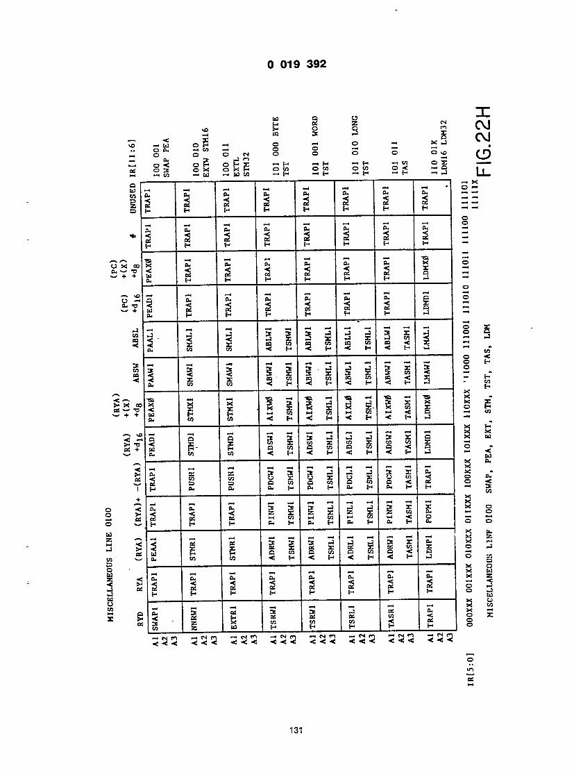
a § % 2 S § s
— i t5 o h" — i o ~ • o
a r c • n c s c 3 E
1 I I 1 co s V @ + I I
vO < TJ +
cn
3 cn pa <
oo TJ +
—4 •o +
V.VJ
• § o " S cs § o o o ( 0
cu > _ n _ — » n 2 o H O P X — • H — 1 H — 1 H —cn o r — - — § 5 o S o E P ota o cn o cn o < - G i — . CO — w — W W -1 H — "H — ' H — ' H — ' — LL-
1 1 1 1 1 1 1 1 — x
. 3 si 3
_. - g g = = - H H H H H H H - -
————— o - — : — — — °
\ I 1 i 3 I i 1 1
o
2 ? X p a c n c o c n c o c n c a < X — < o <
_ _ -4 _ _ , _ , — | _ | — l — l — I — © H
| 1 . 9 3 - 5 3 S 5 3 S 2 3 J S S ~ £
- _ _, — , — i - c i — i < @» — « ~ i S « 1 g S . 1 1 S g S3 Si S S E g 1 1 3 h 3 h j 3 h j 3 h : 3 = w . ______ @ — , g 3 o a 3 3 3 J J J 3 E 9 3 w 2 § X w S S x c n X w c n X ~ m £- E Q t n Q w O c n Q - < 0 £ 53 5 S , H = 4 H « H « H J ~ _
x a,
< " w u £ o x w £ u c n - j 2 2 : S = = Q c n Q c n o w o - < 0 6 o «< H £ £ E H P - H t - r H B - H H "* E5
—i — @ — 1 — ' — i — — • — « - ' — < — ! ~ ; 3 — . a- a, s- 3 3 . 3 - 3 _ i _ 3 X X x 2 2 c2 cs m c n » - ( c n i - ' t o i - i < p — £ H H ( _ H f t . H 0 - H f t . H C - o o
_, _ _ — , — , — i — i — i — i — t — < — t 3 Z~ 3 £ os 3 3 3 - i ^ _ 3 r . f t ; * m C £ Q c n c a c n o c 7 5 o < e a — >
_ _ _ -. — 1 — — — X U 3 S p . f t . f t . f t . f t . e u P s _ 2 2 c 1 2 o l 2 a l 2 g o _ 3
s i l g i i i l l i s
5 3 3 - 1 3 3 5 3 2 3 3 3 < 3 3 3 3 3 3 3 3
0 m B6*
131
w S S = Q c n o c n o w O f C p s 2 S T h £ £ C U H P - H ft. H ft. H H - 3 ____________-_-————— _ — — — — — — — -————__--_——_— ^
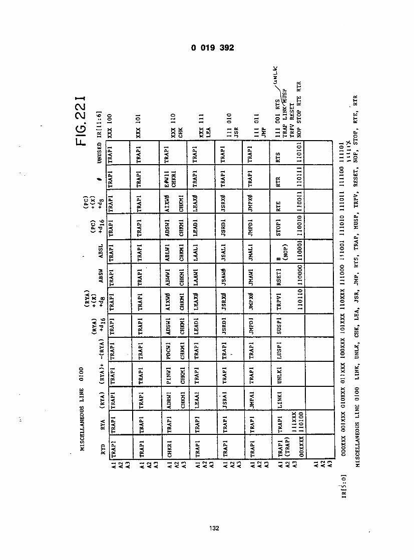
CC I— c It V. 1
X c T + @»
' — \ v o @ ft. -,
*• 0 p
c p
>4 • as @
1 C3 oil P - V H otf
os
£ to cu o — • o — O — > — — u o w O O —i — — 1 — 4 O .— 1 OS H H m — I — i -h O © O CO OS ft, > . X X X!*4 -.OS — • cu — • •< o. eu X X X 35 X W — i co — X — OS OS O ft. X X XO X -3 — — @ — i S — H H 2 O
, , , , , , 1 1 — | H — 1 — i ?C CO — 4 — « — 4 — i — — 4 O O — e u c u e u f t . f t . e u — _— . Si 2 Si Si Si 2 f 2 2 z i - o H H H H H H O S — — — Z
—4 O * — ( — 1 — * — 4 — 1 — 1 — I — O H eu eu — g eu cu eu os © Z! cn 2 2 5 b - ! 2 2 H — ' — ' td H H W O H H H e t S — — OS —4 — »
PS- 5- x S i l a\ eu w o 2 os 2 OS i - I B B W W X H — — H H H H j c j J Ti S o i — —
o o eu 0 — 1 — — 4 — 4 — . — —1 —4—4 — ( C O -i cu eu 3 x o o o eu o o o ; < •< n & < OS cu o o — X 2 CC O E M W X H — —
H H @< O -3 -3 co — — cu 1 — < —4 —i—(—< — — < — \ O © S i 3ft, eu 3 X -3 -3 -i a, o o h S 2 e2 p a s e l ^ cn X _ z ~ 1 H H < O -3 •-) -s pas-- — i — . cn
o O OS E — 4 — 1 — — — ^ — — O O 9ft. ft. 3 £ 3 3 2 H O O - a <! 5 2 @< @< < W O — f t . 2 2 c2 P3 SB @< CO X CO — — x H H 5 0 i J -> 5 OS — — -
O X « —i — i — . — —a - i ~a — < — x os soft. PU 3 X K X X > — X C O 3 ^ @< S 2 3 2 a. a. o o <-> , 2 2 w as w to x ps — — H H < O -3 >-> ~ • H — ""' < X W VO — 4 — < 1 —4—4—4 —4 —4 — X — 3 — i ft. ft. 3 X O Q O ft. X o < @< cn 2 < os eu co — t- 2 2 q s s H co x o o u t
H h @< u -3 -i n co — as X < — 4 —4 — 4 — 4 — « —4 —4 —4 X * w ft, Cu 3 X eu Cu ft. ft. X ^ 5 2 2 O SB 2 2 - 2 s O X I H H ft. CJ H H H -3 — . O
». — 4 —4 —4—4—4 —4 — — 2 '• <ft. CU 3 g C u ft. Cu X X 2 £ 2 2 - x 2 2 2 si s 3 - @ H H C U C J H H H O O
X O B S S i i i s - i z s ! S s a s 2 2 e a a s w co x — — - •H H < C J - 3 T) *0 J O Jl
X O X — _ -4 -4 -4 —1 — — • X O X - 3
< ft, ft. ft. ft. ft. ft. ft? X — X S 2 2 2 2 2 2 2 = 2 S
H H H H H H H — — ° P , - - . - . - - - S B a 5
peu eu os eu ft. a. J S * i i 2 2 i 2 2 2 2 g | 1 | H H O H H H H — ' O O O — i « r i — . m n — c n n — .cm— j — < cni <n - n n — cs tn — . cs — . —
"o "in
OS »—
132
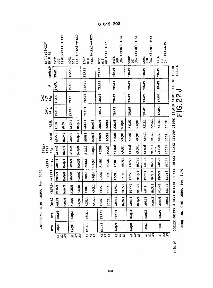
4 ♦ ♦ < 1
• $. cc
\ ft i @< a i r-
0 t < a h
0 C ) « B r e - - c 3 @< C E 1 - 0 : 1 i
a i
? !
vC . T3 +
3 v as
I t •<
^ — * *-s »J f f — 1 OX 2 — X. 2 O 5 H — i h o @< 2 — < Z O < H — „ 0 2 o o 2 o — cs >* — > a. P o w o o w o - • w Sh - a . ow s o ' - ' j o w co o a co — —' 3 — • w j— eo — —
| 1 1 1 1 1 1 1 — Xi , —4 ' 1 — 4 —4 — H •— < ' — 1 © — , ft, ft, ft, ft, cu cu CU -4-4
_S Si e§ .2 - e§ Si Si —i—i ; H H H H H H H - -
, _ , — — — — — r 1 ° C u C U P k C U O u C u C U - 5 S „ SS - Si
-H — 1 " : 2 2 2 2 2 2 2 © C M ! 1 1 i i i 8 8 S c o
o • J - 4 — 1 — 4 — — — — — f O u e u P - c u e u a j f t - f u O V-/
S h h h h h h h - | _ _
a f i | l 3 s ! 3 S 3 3 3 x ^ 2 3 8 - -
sa— 4 - a — is i — is i — -si — « l — « ~ i — i — @ ' X i
S & § 3 & £ £ 5 5 S § l | g | § 5 |
"' _ _ _ 4 - 4 - , - , - - - - - - - - - S § ' 3 3 3 3 — ' ^ 3 0 3 3 3 3 3 — ' J S c o x a o o - u o - u o- u u u c o o- u o- 0 CJ O CO £ 2 2 2. £ x £ w f t , 2 f t < 2 f t . 2 f t ' W -
i ^ i c i - s ^ i g i c i i & s S i g - i . 2 f l x ! S x ^ S S - i £ 2 3 x ^ S 3 § '
g E g B - c s ^ g g g S § ? - Q - < o < o o e a < C 4 < 0 S Q c j - 4 o
S I I h S - c I h S s
1 i | I 1 1 1 1 i *
2 c 2 2 c o 2 2 2 c f l o
3 3 3 3 3 3 3 3 3 3 3 3 3 3 3 3 3 3 3 3 3 3 3 3
o
OS —
133
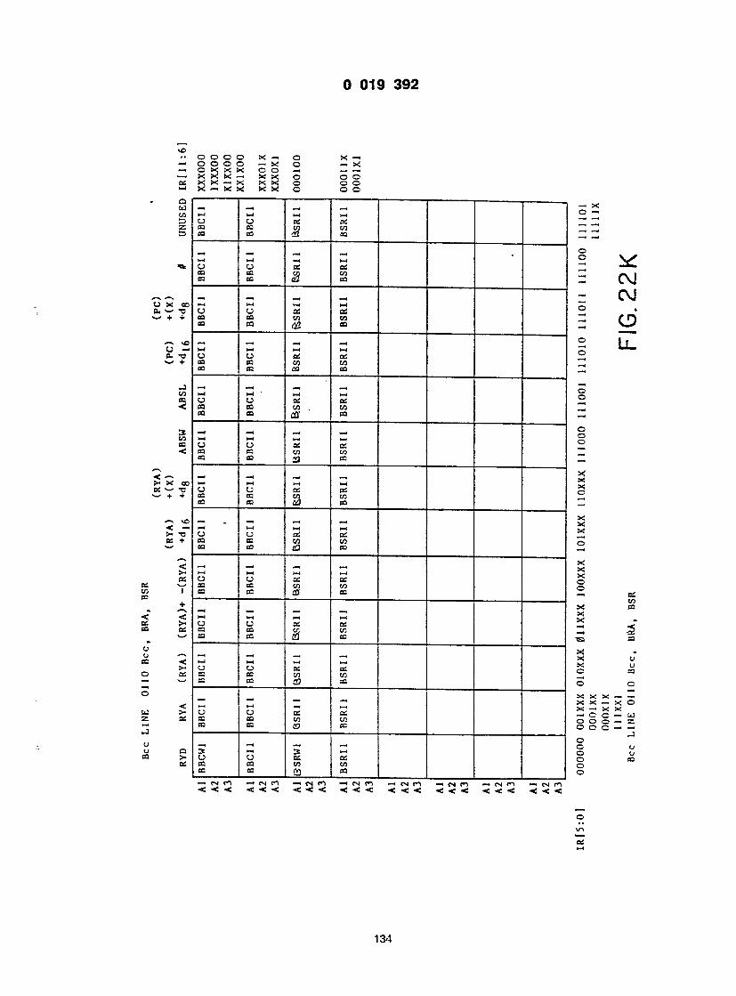
— X — X o o o o
u BO CO
I— ( CJ CO CO
—4 CJ co C9
1-1 CJ 03 CC
M o 03 03
h- 1 CJ CO cs
i— * o cs a
i— < CJ 03 CO
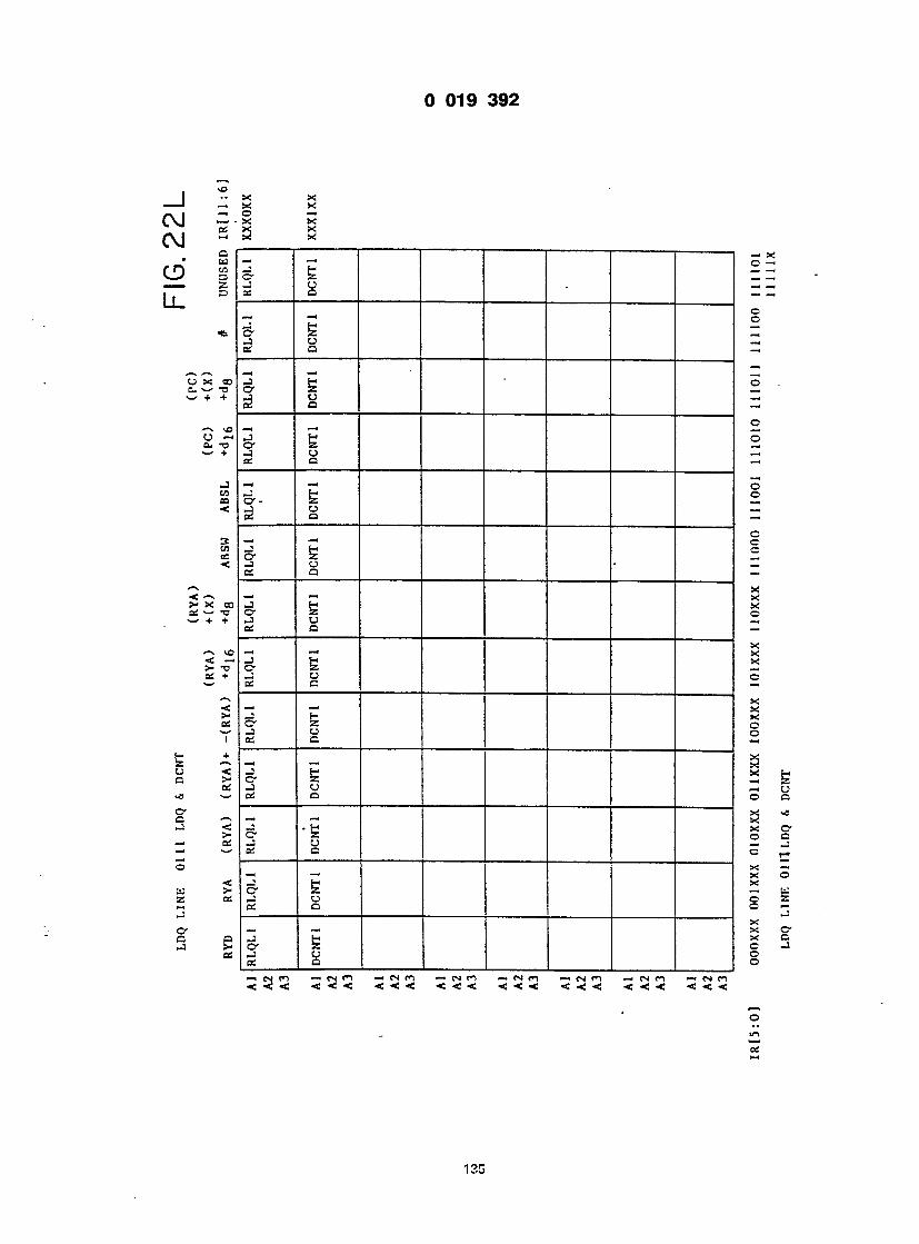
X a
I i I I I I i 1 -1 x £ ! = -
_ _ H ; = - o
E ! cj — a _
_ 2 - cj — o —
o — — I g 2 u — i a _
5 I o _ a —
c
_ I
cj — Q — " X
5 2 0 — i _ _ _ _ _ _ _ _ _ _ _ ______ ^
_ s
_ _ | I 2 X
H X 1 § -
I I - 2 g CJ _ CJ ea o a
• b x c SI © Q °. - J = c _, —————— —————— —_———. _ — X o _ - B CJ © Z Q O —
I I x — X O- H X C Z C J CJ o I a j j o ro — i cn ro —icsm — i n n — « cn co - n n — @ cn co — < cn ro < <<!< < < < < < < < < < < < < < < < < < <
© m cs
135
4 y :
•4 3 y 3
@i 2 y I
H J 5" J
N V-
-
— r ~ — r r n - 1 —
2
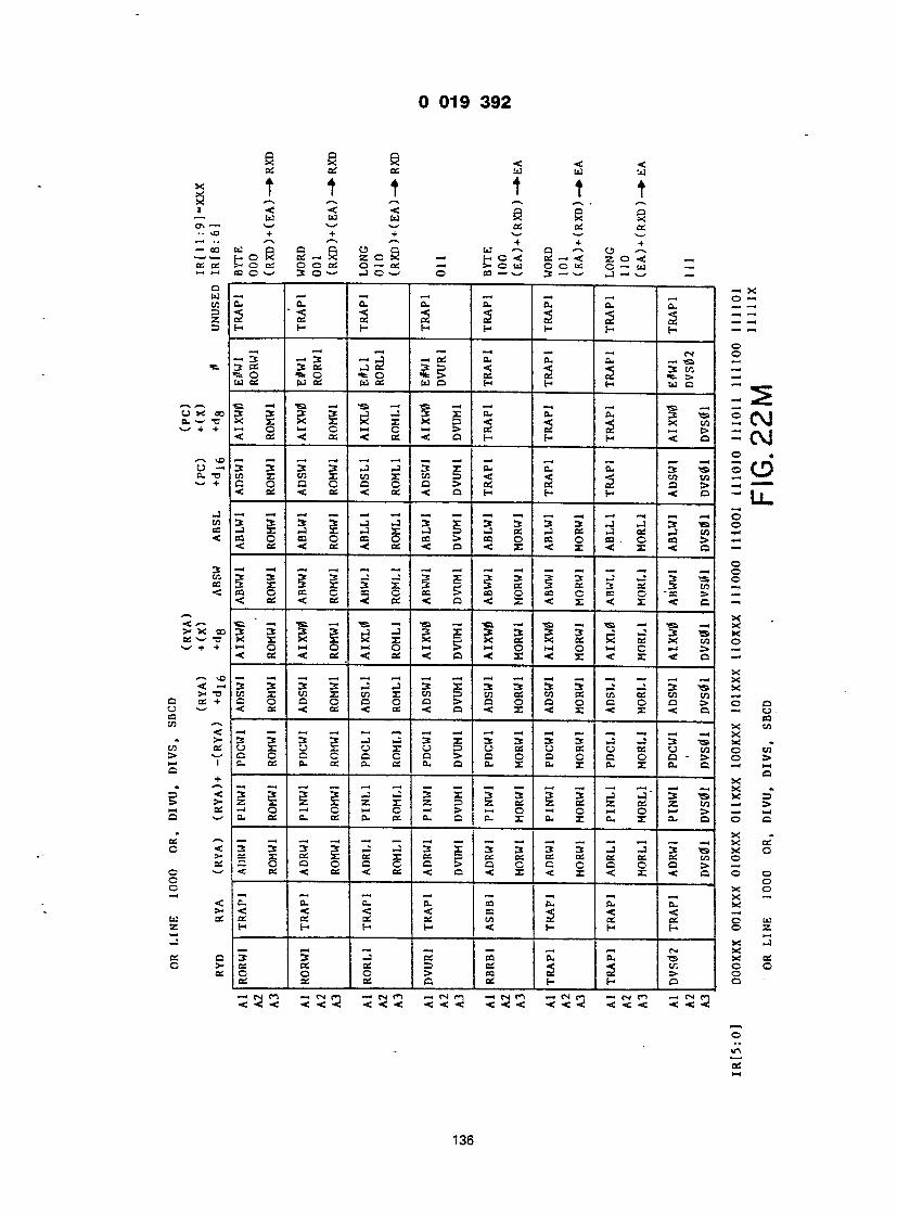
02 CC CS ll t t t 1
< < < c w w w 5
H i • - 00 ? _ -i _i
O til CO 2 o
@ft
< OC TJ k +
vC 3 - - TJ -- +
J CO CO <
3 CO CS <
< oc -- TJ <r +
< ~ >- TJ S +
@s ' — * t
+ -f + w w a a ea o p w — . a » cj — @ H O X 02 — S z o H — H ° < cs — < z o <: — >• o cs O o cs O — ai —> o u O O — C — < W — CO O — @ 30v- ' _) O — @ O CO — • w 3 _ _@ _3 — i w _i
Cu o. cu cu cu cu cu a. — @ — 2 '2 2 2 2 2 2 2 : : - : H H f- H H H (— H — — .
o _ — « _ — » _ « . — _, CN O — 3 — >3 — i -J — oi cu eu eu — -co — 5 § <e§ 2 2 2 2 g : W OS WO! WCS WO H H H w a — _
x | S l x ' x , I i S ?j 1 ^ 2 CM O — O « O > > ai ai os — i e» — i _ . < e e < o s < B t : < O r - H H < 5 — £ \ J
_ _ _ _ _ _ _ _ _ _ _ _ _ 2 • 3 3 3 3 J - 1 3 3 : c u eu cu 3 "S 5 f 0 c n x c o x c o x t n p - < <: < c o t o — >— ' < c S < c S < c S < O H H H < 0 — | |
a—* 3 3 3 3 J « J 3 r 3 3 3 3 J - J 3 - a o - J r - J r - J X J S - i c f i j c s j c s ^ j c o — i c o o c o O c c o o 2 S > c o o b ; o c o . O c o c > — < < _ « < c s < c s < a < x < x < x < a —
o 3 X 3 X 3 Z 3 ; ? 3 c s 3 o : 3 c S 3 c o — . B S C e s C o ; c c o t > e o o c a C B = 0 " a 3 S > - — • < c s < : c s < e c : < o < x < x < x < c — S - i ' S - " « - ' 8 - i « - < « - . 1 S - « ' S - . s 5
! — O l - l O M O > H > M O W O t - l O l - l > - < < _ < c ! : < e r : < o « < x - < x < x « : o - < X
- 3 3 3 3 J J 3 X 3 3 3 3 J - 3 3 - S X c o X c n X c o X t o o c o c S c o c S c o c s c o c o — . a o e G a o a > a o o o e o o : > o o < * < C C < c C < B < I < I < I < o - U - ——-—__ _______ ______________ CO 3 3 3 3 - J - 3 3 X 3 3 3 3 J _ I 3 — . X o x o £ o x o 5 o c s c j c s o e s u c o o c o o o a c a o e > a o o c a o a - s» o > c u c s c c s c u c s c u o c u x c u x e u x c u o — < i - i a X _ _ _ _ - J - 3 _ 2 3 3 3 - l _ . ' 3 _ X O — x z x z x z 5 _ _ _ e t f _ . _ £ « _ @ > — i O — i C h-" C i > — @O — O — i O i - ' t v — i i - i e u o s e u c s e u c s e u c e u x e u x c u X B u o . o o
X 3 3 3 3 - 3 - . 3 X 3 3 3 3 - J _ 3 — X O S X « X _ _ _ 5 b : c s c s _ c s _ c e : c o o — o o c a c a > a c c c e o a > — . < c s < c s < c s < a < x < x < x < a o o 1 1 _ _ _ _ _ _ _ _ _ _ _ _ O _ _ _ _ _ x o e u c u e u c u c o c u c u c u x < < < < o s « ; < < _ CS CS CS CS CO _ cs cs © w H f- t- H < H t- (-> © 2
X -1 3 3 -3 CS CO o. cu —. x c s cs cs cs D _ <; <; a: c c o o o > « c s i _ > o cs cs cs a cs h f- a o
<<-<c! < @«! < <<«c| <@<< <<<! < < < < @< <j
o in oT l—j
136
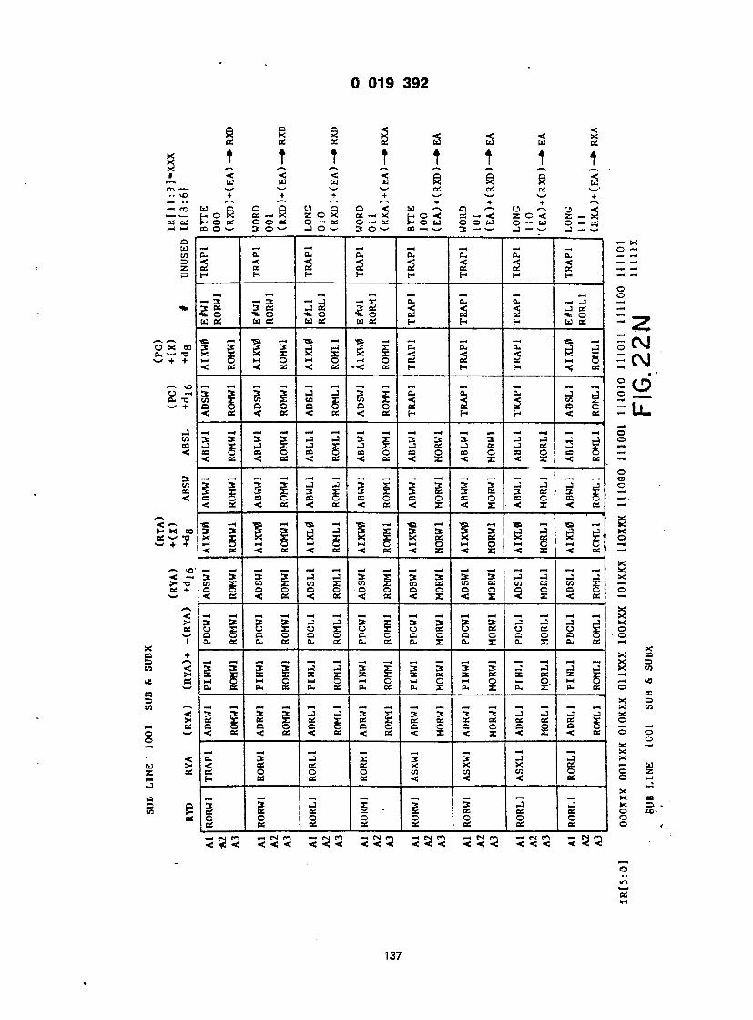
137

CU _ H
Cu _
cu _ H
Cu z H
CU _ H _4 CU < _ H
cu
j-
CU _ H

a r g a <
@ \o @ eo ! _ 4 — 1
a W co => z
c" oo • +
s VO 3 — ' u — +
J CO co @<
co CS
< cc TJ t +
v£ <e - x —
7 T T T < < < s r.i r.i r»i S
t p.
a: t
s w w w cc os os — @ + + + + * — V • ' 4 4 4 . H o H os — R z o R 2 ~« x t- ° •< 2 — < z o < z — x !»oos c o as o— 'os o — cs s -ow o o w o — < w o — os co o w 3 © >— —1 © 3c O — • aa— iw 5c — . — @ — i — — @
— X —I —1 — 1 —1 — H —1 — 1 —4 O— 1 CU . Cu CU CU CU CU CU Cu — @— '
(_ H H H H H H f- — — O
3 " — 3 —-3 — X cu o- a- —j — < @jog a cc — ioS 3 2 <: •< @< *_ e_ — C eu ** Cu % b ftCu OS — OS "to. — WO WO WCJ WO H H H WO — @
_ — I - — > - < - < — ' — * — V_/ g 3 g 3 , - J , — ! g X . C u CU Cu _ ] J O — • _ u - i c u i - i c u — c u 2 2 2 — iu — C\J < 0 < 0 < 0 < O H f- H < 0 —
3 3 3 3 J - 3 3 x e u eu eu — 3 c / r T e o £ c o r c n X c o - < < < co X — C__> < 0 < 0 . < 0 - < O H H (- < O — — - "
3 3 3 3 J - 3 3 X 3 3 3 3 - i J J J O -J X — X - J X - ' X J O S J O S - l e - J X - ' c S b c s c u c a O u c c o < s o c a o c a o c q c u — < < o 3 o < : o < o - < x < X ' < x ^ o — o
3 . 3 3 3 t J . - 3 X 3 3 3 3 _ . J c J j e 3 x 3 X 3 x 5 X 3 a : 5 o S 3 e - 5 x — c c E c o e u c o e u e s c u c o o c s o c s c e e — — < o < o < o < u < X < x - < X < o — X ^ — l — — J — 1 — 4 _ » — -^l— 1 ^ 5 — » ~ » — » ~ i — < X
i— i c— i - @— i c u m c u i - i e u M O » - i O > - i O ' - i e u — i < u < u < o < u < x - < x < x < o - X
. 3 3 3 3 J - S 3 X . 3 3 3 3 — J — J X c o x c o x c n x c o x c o c s c o o s c o e c c o x — ' o p u e - e u c a e u a e u Q O Q O — c o e u © < < o < o < o < o - < x - < x - < x < o - < f t : x 5
3 3 3 3 - . - . 3 X 3 3 3 3 _ - 3 J 1 _ l X - o x o x o x o x o o s o o s u o s o x o x o S Q c u a e u a c u o o o o a o o c u o c u e u o c u o c u u c u u c u x e u x c u x c u o - H ^
3 3 3 3 - t ' - 3 3 X 3 3 3 3 - 3 _ 5 _ — X c s S x S x z x z x S e - z o c z S z x — o >—i Ki— i e u > - i t u — eu — i o >- i o > - i O t - i c u — < w c u o c u u c u o c u u c u x c u x e u x e u o o X CU
3 3 3 3 J J 3 X 3 3 3 3 - ! - 1 J _ X O o s x o s x c s x o s x o s o s c - o s OS OS OS X O o c u C B . a c u o c u Q o c a o a o c > c u — > < o < : o - < o < o < : x < x - < s : < o o — X o
£ * 3 x _ 3 - J > < ~ " <l os cs 2 x X £ « — • _ oS Cu eu cu x X X eu o Z H U o o o D o o ° _
5 o.
. e u e u c u e u O O O C u © C J C J O O O S O S O S O O — i cn ro _ cm ro — • <M ro — < cn ro — ' N n — ' cn ro — ; cn co — cn ro
O m OS i—i
139

Oi OS 0- t t t < < < w w w [1
**7 CO 02 xi 0 r w
§5
ft
co tj +
•a • +
J CO CO <
3 co cc <
1 CO ' TJ • +
- VO : — i TJ i +
— * — * W W u T t t
s e s — — ' — ' OC OS cc + + + — • w v_- — , — . — < . + + +
i_oH oi — H - o R — h o •< 2 — < z o <: Jmocs o o os o — os —" Show o o w o — < w — i CQOw 30s—* O — ' O CO hw 3 — i w — ' — 4 — - — - — X
— — — — — —4 —4 —4 O— * Cu Cu CU Cu Cu Cu Cu Cu — ' — _ _5 Si cc* _ 2 Si 2 — <— < H H H f- H H H H — ' —
O —| —4 —4 — —4 —4 —4 — 4 O — 3 —3 ~" ' cc —OS 0- 0- Cu — « a; — ft O ft O ft O S_5 a\ a\ 2? ft — > — wos was w os war h h t-> w x —
— _ —4 —4 "Si —4 TSl —4 —4 — i —4 ^ — | — t g g l r ^ _ l 5 | | < g | 2 C M — O — O — O — s a i at oi — O — _ . - e o s < o s - : e _ - < r H h h < x — £ \ J _ _ _ _ - _ 4 - _ ~ ^ _ _ 2 * 3 3 3 3 - J 3 X B - al lu 3 x © (_n c o r c o £ c o X c o 3 - < •< < en 3 — v— p o o o o o o o o d OS ai o o — - 3 b 5 < o s < c _ < x h H h -< x — | j
3 3 3 3 — - 1 3 — 3 3 3 3 - 1 — 3 3 : 0 3 £ j £ j s - 4 3 j b s _ 5 c - j - c i ! _ 4 3 — c o o c o O c Q O e s s e a o c s o c o o e a s — < a s < « < o : « c - < r - < x < - : < — — _ 0 o 3 3 3 3 - 4 - 3 ? 5 : 3 3 3 3 I J - . 3 - 0 3 s 5 £ 3 r 3 J 3 « 3 « 3 c _ 5 3 - - c a o c q o c Q O c c S B O O c c c c c o c o o — • < < _ < e s « < e _ . < x < r < x - « : _ < x — g
X w _ — 4 j _ i — 1— a — <— s — 4 _ — 1— s — 4— a — 1 _ — 4 x
— O — O 1 - 1 O — 3 M O W O — O — O — H < e - < o S - < c _ < X ' < X - < X - < X - < X — X
3 3 3 3 J ~ 3 X 3 3 3 3 - _ 3 X X O c o £ c o £ c o x w - < c o c e ; c o o 5 c o o s c o j — p Q O O O O O O — i p O Q O Q O Q O O i X < 0 S < c _ < 0 S - < X < X - < X - < X < X — w X
3 3 3 3 J J 3 X 3 3 3 3 - J J 3 X a u G £ o £ o x o J o e c ' o a . o e c . o Z i O c o Q O O o a o Q o a o o o o o o o o < c _ e _ c _ c _ B 4 c _ f t 4 X f t - x o - r ( - x o 4 X —
x 0 3 3 3 3 J - < 3 X 3 3 3 3 J _ 3 x x ! : = £ £ z £ z x — - ' Z o s z o s z o s z - i — x — O — O m O — o — o — o — o — 0 — 4 O - C t f C U C - B - e - C u X C u X O - X C u X O - X O -
3 3 3 3 - J - J 3 3 : 3 3 3 3 - 4 - 1 3 X X 2 £ e s £ e £ x e c — « c _ c _ e s c - e e : c _ _ i © Q O Q O C O Q O O O Q O Q O O O — O @ < o s < o s < o s < x < x - < x < X < x o o
— 4 — 4 — 4 — 4 — —4 — — 4 X C U C u C u C U C O W W C U X < < < < CO O CO «e — W 2 2 cs 2 co x x c - o z (- H H H < W W H _
_ x g 3 3 -3 os co w eu os *S 3 at S OS -3 OS O «£ — © < § § § § S w S § §
3 3 3 3 3 3 3 3 3 3 3 3 3 3 3 3 3 3 3 3 3 3 3 3
0 u-i OS —
140
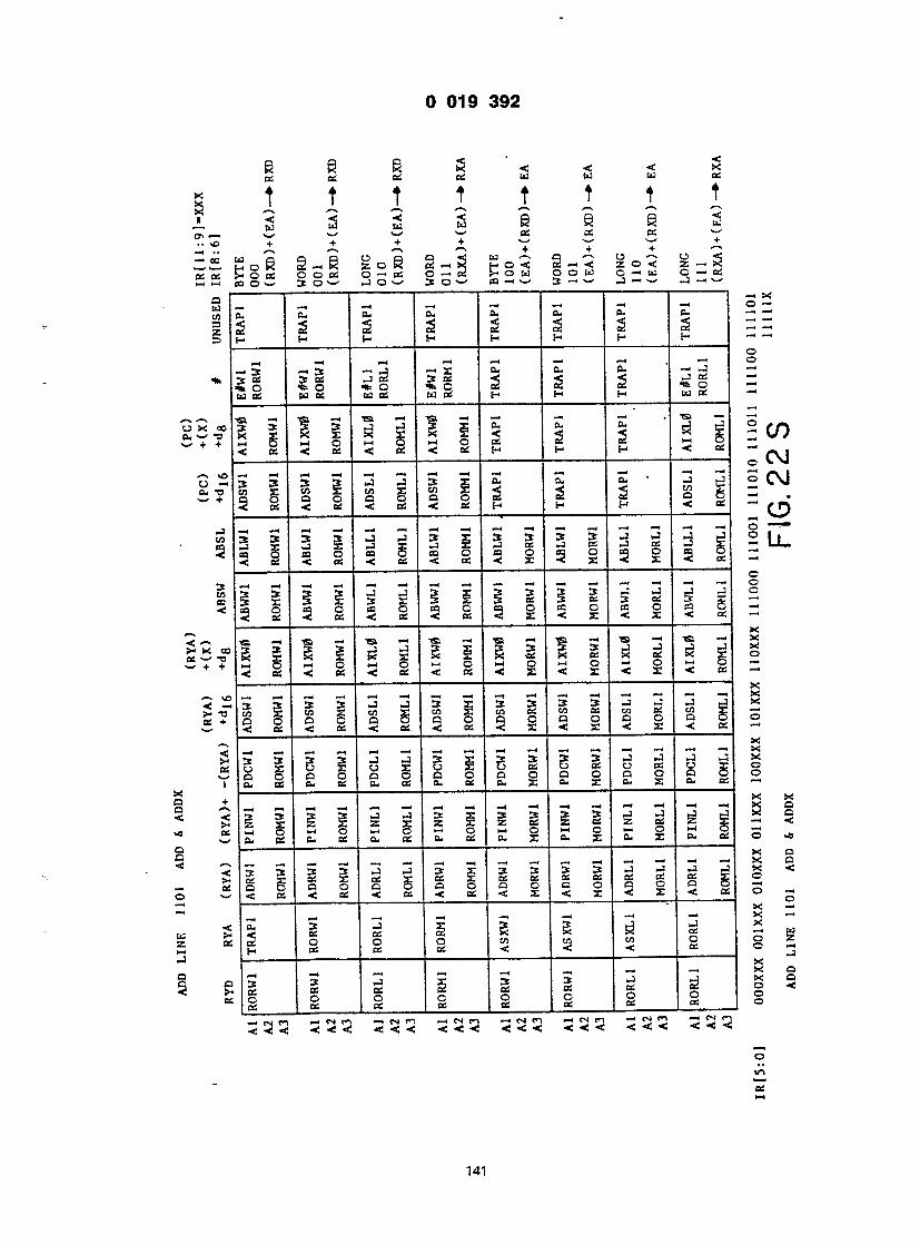
(X Q5 _ A _ _
30 I £ ! —i i q r to
%
00 TJ +
vO —4 +
— to CO <
3 to CO <
co +
—I — I +
T T T T T T T t
C — < ^ ' O S as cc — '
- o B § - B S o l S - h S g o ^ § - 3 g o < g - g i- o « ooos o—os o — 2 Show o o w o — ui q — os CO O w 3 © — • -1 © — @ 3 O — ' CO — —' 3 - . w J — — -]-.—@
1 1 1 1 1 i 1 i — ' x _, — ( — . -. — - - o - a, b* cu cu cu cu cu — — -S Si SS Si g g g (h t- H H H H H — —
o _, — 1 — 1 _, — , — 1 — 1 . — . O
— 3 — » 3 — • j — 1 X 04 — '— J — 2© «!§ - - g _ i =* tdOS WOS t- ctl L_ c_ H H H woe — •
S o S o w S w o c c 2 2 2 £ < c _ < ; b s < b s < c _ h h h < cc —
o - * 3 3 3 — I J 3 X 3 3 3 S - 5 — l i - 3 J O ? ? 5 E 3 _ 3 £ 5 c - 3 C - 3 c - 5 - - ' c o o - O p a o c o o c o o s o K O g < c _ < o S < o S < B S < X < X < X < o ; — @
X I x x x x ' x ' x i x - I e l x ' ^ ^ g g 3 i 3 § 3 § 3 § 3 § 3 i 3 § 3 _ : - .
_ "
- - - - - - - - . - . - - . - - - - . a • * 3 3 3 J ~ 3 3 X 3 » 3 3 - ' ^ - 1 l _ ! : , < c o £ c o X c o X & £ w £ « « ; S £ K £ ; = : O 5 0 0 Q O 0 0 Q 0 Q 0 C 0 O 0 O - ^ c i S c s 3 - < o s i 3 3 : < x < : - < « ' - ,
X S x i i d - o i g - i s d g d i i l i s l s i s c i s g s g s i s i s
X X 3 3 3 3 - i J 3 x S 3 S 3 e i s 3 ^ e i 2 2 S £ £ £ z x z £ z b s _ ; b s z o s — x — < <
- * a 3 3 . J » J 3 X 3 3 3 3 — ) H l 3 _ 5 S < : S x c _ £ c C X C - £ c c c B c c c c e _ o S o s X © Q B O O C O Q O O C O O C = O O S — < 2 < c _ < o s < o s « : x < x < 2 : < o s © -
x — 5 i i i x S x ! | g
X
3 3 3 3 3 3 3 3 3 3 3 3 3 3 3 3 3 3 3 3 3 3 3 3
o in OS 1— 1
141

cn f- a _. w a cj _ i-i P at z o x i o i o I 3 » a o ! 3oi Joi '
Id Id U — i>- Ot-W — H cn OHW — — O tn H O M H - w H — < x o x — tx. x — ex. x — U. x x x x o — x o — xo— x X E X Cd X X Ix) X X tx) X X c X x cc cn X cc cn x ec cn — i I I I 1 @ I I I I — x — I — H — H — I — O — eu 3 se J ft. — —
2 « _ i 2 - - CC CC OC CC CC — @ — ' H cn c/3 cn H — < — @ o — i — t — i — @ i — o eu 3 3 J eu — < ec cc ec _ — i CC cc cc cc cc — H cn cn cn h —
cu 3 3 J 0- O «c cc as, at < — . 2 at oc cc cc — H cn cn cn H — _ _ _ _ _ s , _ eu 3 3 -3 eu o — . | _ 2 _ _ 2 ~ C\J o S o S O a c c c c — . t- cn cn cn t- — r \ l
3 X 3 3 Zj 2 O ( r \ J P cc cc cc @< — . V_«/ CQCx.BC CC CC DC — • «m— @«: cn cn cn cn s- — . o L— '
— I -H — 4 — « — I — 4 © 3 X 3 3 -1 eu o 3 P cc as 2 < - cc _. os aS cc as — < cn cn cn , cn t- — x @c — — — — — X
X p" as W S? % g — to, cC OS OS CC — < cn cn cn cn h —
x — i —i —i x 3 X 3 3 J ft. X cn P as as 2 — O C_ CC CC CC OS o x < cn cn cn cn H — X o s *
B X 3 3 J cu x - P cc ec cc @* o x q u, cc os os os o o B. cn en cn cn H — os —i — — — — — x x* 3 X 3 3 —3 ft. x c n Z P — — — < — J — ex. os os os oS — < a. cn cn cn cn h o - _ _ _ _ _ _ _ _ _ _ _ ______ x I X cn — t — — — i — -t — . — • x < 3 X 3 3 _: c- X OS H — — " — < O O O t x . C C os os cc — — < cn cn cn cn h o —
X eu 3 3 Zi cu x z «£ t-i i-h _» <; — , _ CC CC OS CC BS C — (_ cn cn tn t- o 1 (-. X — x — ft. 3 3 J cu X X «< — — " " < o cn 2 os os os cc o H cn cn cn t- o — ts n — 4 cn co h m n - n ri — n n — « cn — — 4 cn ro — n tn < @<. < < < «4 < < < <@<•«; < < < < < < < < < < < <
O uo BS
142
OS — o u cn D
— =
X c — TZ + +
• — * V. o @ eu - — > +
v. cc <
3 a a «s
x ( w - + -1
< • OS H
— 1 S- Q H w — •— cn OHM — — • cc 0 w h ocnH — tn H — XO X — fx. X — Cx. X — tx, X x x x o — x o — xo— x x E x i d x xcxix x u x x c x x cc cn x ec cn x ec cn —> — X — 4 _H — 1 —J — O — eu 3 3 j cu — — .
2 g _ i 2 - - OS CC CC CC CC _4 _4 H cn cn cn h — . —. 0 _4 _ _4 _4 _4 O ft. 3 3 J cu _. 45: ec cc cc _ _ CC OS cc cc cc — H cn cn cn h —
0 eu 3 3 J eu 0 «C OS OS cc < — 2 os cc cc 2 — H cn tn cn H — 0 h -
□ — 1 — 1 — . — 1 — —
_ _ _ s 2 - C\J o s c c c s c c c c — . f- cn cn cn h —
- . — 1 — — 1 - 4 — O * 3 X 3 3 - 3 0 ; 0 f n _3 P os os cc 4 _ V_y CO Cx. BS OS CC DC — — < cn cn cn cn s- 0 L— '
_4 _4 — 4 — « —4 _4 O 3 X 3 3 _3 CU 0 3 P ec eC 2 < — CO Cx. BS CC CC CC — < cn cn cn , cn t- — X @»_ — 4 — 1 — . — 1 — X o 3 X 3 3 _ 3 f t < x > R P os os 2 < 0 — Cx. CC OS OS cc — < tn cn cn cn h — X 0 — — — — — — X - > 3 X 3 3 - J f t . X j cn P ec as at @< —> Q C X . O S O C C C O S o x < cn tn tn tn H — x O
' 3 X 3 3 - 1 C U x - s t j p c c e c c c < : o x Q _ CC OS OS OS O O c u c n c n c n c n n — o s V— 1— 1 — 1 — l - 4 _ X X" C 3 X 3 3 - 3 B . x c n - Z P — — — @< — _3 S — ex. OS OS OS oS — < ^ O u c n c n c n c n t - 1 a - -——_—-————— _______ X X cn V - 4 - 4 — I - . — 1 — X < S 3 X 3 3 _ 3 f t . X H c C H — — " — < 0 0 S O Ix. cc cc 0; 0; — — ^ < c n c n c n c n H 0 —
X < e u 3 3 - 3 C u x z _ 4 £ ) _ i i _ i _ . < ; — . _ C 2 CC OS OS CC c — (_ cn cn tn t- 0 1 u. X Cx. — X — 2 eu 3 3 j cu x x M 4 « ; i _ i — o c n _ 2 OS BS OS 2 0 H tn cn cn t- 0
p_rsro — 4 cn co — CN ro - N n -—cnco — « cn ro — 4 cn ro _cnco <<•<; < < < <@<•«; < < < < < < < < < < < <
0 UO BS —4
142

1 1 — I — I 1- r — X