DIGITAL SATELLITE NEWS GATHERING CODER / DECODER
188
INSTRUCTION MANUAL Digital Satellite News Gathering Coder/Decoder Firmware Version 2.0/2.3 (and later) M2/ESN/SNG and Options ST.TM.E5910.5 Issue 5 ENGLISH (UK)
-
Upload
khangminh22 -
Category
Documents
-
view
3 -
download
0
Transcript of DIGITAL SATELLITE NEWS GATHERING CODER / DECODER

INSTRUCTION MANUAL
Digital Satellite News
Gathering Coder/Decoder
Firmware Version 2.0/2.3 (and later)
M2/ESN/SNG and Options
ST.TM.E5910.5Issue 5
ENGLISH (UK)

Preliminary Pages
Page ii Instruction Manual: Digital Satellite News Gathering Coder/DecoderST.TM.E5910.5
SVENSKA
LÄS DETTA FÖRST!
Om Ni inte förstår informationen i denna handbokARBETA DÅ INTE MED DENNA UTRUSTNING.
Utbildningskurser för utrustningen i DSNG kan anordnas genom kundtjänstmed den information som finns på de inledande sidorna i denna handbok.En översättning till detta språk av denna handbok kan också anskaffas, på
Er bekostnad.
ENGLISH (UK)
READ THIS FIRST!If you do not understand the contents of this manual
DO NOT OPERATE THIS EQUIPMENT.Training courses on DSNG equipment are available through Customer
Support using the information in the Preliminary Pages of this manual. Also,translation into any EC official language of this manual can be made
available, at your cost.
ooy
my|ytqyy
y²¨©²¯¥¸¥°¦©¸©¸³´©¶©¼¢±©²³¥½¸³¤¸³½¦³¬¹ ±¥¸³»©«¼©¶¨¡³½oltypqot
¥¹ ±¥¸¥«¥¸¬²¯¥¸¶¸·¬·¥»·¸¬¼¶ ·¬¸³½'61*¥½¸³¤¸³½©®³´°·±³¤¨¥¸¡¹©²¸¥±·º¸³½&XVWRPHU6XSSRUW¹¥¦¶©¡¸©¸»
´°¬¶³ª³¶¡©»´³½¼¶©¾©·¸©·¸»q¶µ¸©»t©°¡¨©»¥½¸³¤¸³½¦³¬¹ ±¥¸³»´¡·¬»¥½¸¢¸³©«¼©¶¡¨³©¡²¥¨¥¹·±³·©±©¸ª¶¥·¬
·©¥½¸ ¸¬«°µ··¥¯¥±´³¶©¡¸©²¥¸³¥«³¶·©¸©
DEUTSCH
LESEN SIE ZUERST DIESEN HINWEIS!
Sollte Ihnen der Inhalf dieses Handbuches nicht klar verständlich sein, dannBEDIENEN SIE DIESE GERÄTE NICHT!
Schulungskurse zur Bedienung des DSNG bietet Ihnen unserKundendienst. Die entsprechende Adresse entnehmen Sie bitte den erstenSeiten unseres Handbuches. Eine Übersetzung des Handbuches in diese
Sprache ist gegen Berechnung lieferbar.
ESPAÑOL
LEA ESTE AVISO PRIMERO!Si no entiende el contenido de este manual
NO OPERE ESTE EQUIPO.El servicio posventas (Customer Support) ofrece cursos de adiestramientopara el manejo del equipo del DSNG usando la información en las páginas
preliminares de este manual. Podemos asimismo suministrarle unatraducción de este manual al (idioma) previo pago de una cantidad
adicional que deberá abonar usted mismo.
FRANÇAIS
AVANT TOUT, LISEZ CE QUI SUIT!Si vous ne comprenez pas les instructions contenues dans ce manuel
NE FAITES PAS FONCTIONNER CET APPAREIL.Des stages de formation sur le "DSNG" sont disponibles auprès du Servicede Soutien Technique à la Clientèle dont vous trouverez les coordonnées
dans le Préambule de ce manuel. En outre, nous pouvons vous proposer, àvos frais, une version française de ce manuel.
ITALIANO
LEGGERE QUESTO AVVISO PER PRIMO!Se non si capisce il contenuto del presente manuale
NON UTILIZZARE L’APPARECCHIATURA.Corsi di formazioni per l’apparecchio DSNG sono disponibili presso
l’assistenza clienti, consultando le informazioni contenute nelle Paginepreliminari di questo manuale. È anche disponibile la versione italiana di
questo manuale, ma il costo è a carico dell’utente.
PORTUGUÊS
LEIA O TEXTO ABAIXO ANTES DE MAIS NADA!Se não compreende o texto deste manual
NÃO UTILIZE O EQUIPAMENTO.O serviço de Apoio ao Cliente oferece cursos de formação sobre o
equipamento DSNG, disponíveis por intermédio da informação contida nasPáginas Introdutórias deste manual. O utilizador poderá também obter uma
tradução do manual para o português à própria custa.
NEDERLANDS
LEES DIT EERST!Als u de inhoud van deze handleiding niet begrijpt
STEL DEZE APPARATUUR DAN NIET IN WERKING.Trainingscursussen voor DSNG apparatuur zijn via Klantenservice
beschikbaar en informatie hierover is te vinden in de eerste pagina's vandeze handleiding. U kunt tevens, op eigen kosten, een vertaling van deze
handleiding krijgen.
DANSK
LÆS DETTE FØRST!Udstyret må ikke betjenes
MEDMINDRE DE TIL FULDE FORSTÅR INDHOLDET AF DENNEHÅNDBOG.
Træningskurser i DSNG udstyr kan arrangeres gennem Customer Support.Der henvises til de indledende sider i denne håndbog for yderligereoplysninger herom. Vi kan også for Deres regning levere en dansk
oversættelse af denne håndbog.
SUOMI
LUE ENNEN KÄYTTÖÄ!Jos et ymmärrä käsikirjan sisältöä
ÄLÄ KÄYTÄ LAITETTA.Asiakaspalvelu tarjoaa koulutuskursseja DSNG laitteiden käytössä. Tätä
koskevat tiedot ovat käsikirjan alkusivuilla. Käsikirja voidaan myössuomentaa asiakkaan kustannuksella.
Issue 5 first published in 1999 by:
NDS LIMITED
1 HEATHROW BOULEVARD
286 BATH ROAD
WEST DRAYTON MIDDLESEX UB7 0DQ
UNITED KINGDOM
INTERNATIONAL TELEPHONE: +44 (0) 181 476 8000
“This document and the information contained in it is the propertyof NDS Limited and may be the subject of patents pending andgranted. It must not be used for commercial purposes nor copied,disclosed, reproduced, stored in a retrieval system or transmittedin any form or by any means (electronic, mechanical,photocopying, recording or otherwise), whether in whole or inpart, without NDS Limited’s prior written agreement.”
NDS Limited 1996 - 1999. All rights reserved.

Preliminary Pages
Instruction Manual: Digital Satellite News Gathering Coder/Decoder Page iiiST.TM.E5910.5
List of Contents
Chapter 1: IntroductionThis chapter identifies the equipment versions covered by this manual;describes the purpose of the equipment in a typical system; provides asummary of its main features; identifies the controls, indicators andconnectors in a guided tour of the front and rear panels; and lists theavailable options.
Chapter 2: InstallationThis chapter provides a guide to the suitability of an installation; givesdetailed procedures for the preparation, installation and configuration of theequipment including important safety information; and provides pin-outdetails of the the external connectors.
Chapter 3: Local Control and OperationThis chapter describes the front panel controls, indicators and displays indetail; provides the power-up/-down procedures and other generaloperating/control/set-up procedures; and a Getting Started guide.
Chapter 4: Equipment DescriptionThis chapter gives a brief introduction to some of the principles andtechniques used in the design of the equipment to aid in understanding itsoperation and function; and provides high-level description of the equipmentwhich identifies the functions of its main constituent parts, cards andmodules.
Chapter 5: Preventive Maintenance and Fault-FindingThis chapter details routine maintenance tasks to be performed; providesgeneral servicing advice, and information regarding warranty andmaintenance; lists the error messages that may occur, and any appropriateOperator action to be taken; provides general fault-finding information forother types of problem which may be encountered; and provides relevantdisposal information.
Annex A: Glossary
Annex B: Technical Specification
Annex C: Default Configurations
Index

Preliminary Pages
Page iv Instruction Manual: Digital Satellite News Gathering Coder/DecoderST.TM.E5910.5
About this ManualThis manual provides instructions and information for the installation,operation of the Digital Satellite News Gathering Coder/Decoder.
This manual should be kept in a safe place for reference for the life of theequipment. If passing the equipment to a third party, also pass the relevantdocumentation.
Issues of this manual are listed below:
Issue Date Software Version Comments
1 Sept 1996 1.4 Initial release.
2 Oct 1996 1.5 Additional software features: UTC offset, errormasking, low res. low delay mode, remotediagnostics, re-initialise unit.
3 Feb 1997 2.0 IRD Card option introduced.
4 Dec 1997 2.0 (and later) Company logo and style change.
4r1 June 1998 2.0 (and later) Fuse size changed to 5 x 20 mm and CustomerSupport information now includes overseas offices.
5 March 1999 2.0/2.3 (and later) Modulator LCD menus amended to reflect S5898version 2.3. AS/NZS 3548 compliance added. Variousminor amendments.
The following associated manual is also available:
ST.TS.E5910: DSNG Remote Control Protocol (Specification)
RevisionsIt is not intended that this manual will be amended by the issue of individualpages. Any revision will be by a complete re-issue. Further copies of thismanual can be ordered from the address shown on page ii.

Preliminary Pages
Instruction Manual: Digital Satellite News Gathering Coder/Decoder Page vST.TM.E5910.5
Acknowledgements
GeneralAll best endeavours have been made to acknowledge registered trademarksand trademarks used throughout this manual.
Any notified omissions will be rectified in the next issue of this manual.
Some trademarks may be registered in some countries but not in others. Ingeneral, the situation in the UK will prevail throughout NDS Broadcastmanuals.
Registered trademarks and trademarks used are acknowledged below andmarked with their respective symbols. However, they are not marked withinthe text of this manual.
Registered TrademarksAMD® is a registered trademark of Advanced Micro Devices, Inc.
XILINX® is a registered trademark of Xilinx, Inc.
Betacam® is a registered trademark of the Sony Corporation.
TrademarksMACH™ is a trademark of Advanced Micro Devices, Inc.
Dallas Semiconductor™ is a trademark.

Preliminary Pages
Page vi Instruction Manual: Digital Satellite News Gathering Coder/DecoderST.TM.E5910.5
Warnings, Cautions and Notes
Heed WarningsAll warnings on the product and in the operating instructions should beadhered to. The manufacturer can not be held responsible for injuries ordamage where warnings and cautions have been ignored or taken lightly.
Read InstructionsAll the safety and operating instructions should be read before this productis operated.
Follow InstructionsAll operating and use instructions should be followed.
Retain InstructionsThe safety and operating instructions should be retained for future reference.
WARNINGS....
WARNINGS GIVE INFORMATION WHICH, IF STRICTLY OBSERVED, WILL PREVENTPERSONAL INJURY OR DEATH, OR DAMAGE TO PERSONAL PROPERTY OR THE
ENVIRONMENT. THEY ARE BOXED AND SHADED FOR EMPHASIS, AS IN THISEXAMPLE, AND ARE PLACED IMMEDIATELY PRECEDING THE POINT AT WHICH
THE READER REQUIRES THEM.
CAUTIONS...
Cautions give information which, if strictly followed, will prevent damage to equipment orother goods. They are boxed for emphasis, as in this example, and are placed immediately
preceding the point at which the reader requires them.
NOTES...
Notes provide supplementary information. They are highlighted for emphasis, as in thisexample, and are placed immediately after the relevant text.
EMC ComplianceThis equipment is certified to the EMC requirements detailed in Annex B,Technical Specification. To maintain this certification, only use the leadssupplied or if in doubt contact Customer Support.

Preliminary Pages
Instruction Manual: Digital Satellite News Gathering Coder/Decoder Page viiST.TM.E5910.5
Customer Support Information
How Can We Help?NDS provide continuous product support and services to all our customers.We provide assistance with regards to the operation and servicing ofinstalled equipment. We also offer training, maintenance agreements,equipment loan service and provide a base repair facility.
Where to Find UsCustomer SupportNDS Broadcast35 Parham DriveBoyatt Wood Industrial EstateEASTLEIGHHampshireSO50 4NUUnited Kingdom
International Telephone: +44 (0) 1703 498111International Facsimile: +44 (0) 1703 498102
Internet Address: http://www.ndsworld.comE-mail: [email protected]
U.S. Office: +18 - 8863-70023 (8:00 – 5:00 Local Time)Hong Kong Office: +85 - 262-19151 (9:00 – 5:30 Local Time)
Procedure for Returning EquipmentIn the event of a problem with your equipment, please contact CustomerSupport. If it is serious, requiring the return of all or part of the equipmentfor repair, then proceed as follows:
1. We will allocate you a Returns Authorisation Number (RAN) andask you to complete the Customer Repair Report, provided at theback of this manual, as fully and clearly as possible.
2. It would help if a copy of the Customer Repair Report and RAN werefaxed to us as soon as possible (at the number given above).
3. Pack the equipment to be returned in the original packing boxes, orother approved packaging materials. Ensure the completed CustomerRepair Report is included with the equipment to be returned.
4. Ensure the appropriate address and information labels are attached tothe packaging. This may include a Customs Declaration Form ifreturning equipment from overseas.
It is the responsibility of the sender to ensure the equipment arrives atCustomer Support on time and in good condition.
Terms and ConditionsA copy of the standard Terms and Conditions can be obtained fromCustomer Support (see address above).

Preliminary Pages
Page viii Instruction Manual: Digital Satellite News Gathering Coder/DecoderST.TM.E5910.5
BLANK

Instruction Manual: Digital Satellite News-gathering Coder/Decoder Page 1-1ST.TM.E5910.5
Chapter 11. Introduction
Contents1.1 Scope of this Manual.....................................................1-3
1.1.1 Who this Manual is Written For............................1-31.1.2 Firmware Versions ...............................................1-31.1.3 Equipment Models ...............................................1-3
1.2 Function of the DSNG Codec........................................1-4
1.3 Summary of Features....................................................1-41.3.1 Video Encoding....................................................1-5
Encoding Standards ............................................1-5Video Input Sources ............................................1-5Variable Bit-rate...................................................1-5Automatic Configuration of Parameters...............1-6Coding Resolutions .............................................1-6Low Delay Mode..................................................1-6Internal Frame Synchroniser ...............................1-6Output on Video Loss ..........................................1-6Frame Sequence Control ....................................1-6
1.3.2 Audio Encoding....................................................1-7Encoding Standards ............................................1-7Channel Modes ...................................................1-7Variable Bit-rate...................................................1-7Test Tone and Level Display ...............................1-8
1.3.3 Data Channels .....................................................1-81.3.4 Multiplexing ..........................................................1-8
MPEG-2 and DVB Compliance............................1-8DVB Transport Stream Output ............................1-8Security of Transmission .....................................1-8
1.3.5 IF Modulation .......................................................1-81.3.6 Integrated Receiver-Decoder (IRD) .....................1-9
Local Monitoring ..................................................1-9Off-Satellite Monitoring / Independent ServiceReception ............................................................1-9
1.3.7 Unit Control and Monitoring.................................1-9Remote Control ...................................................1-9Local Control .......................................................1-9Reset/Alarm/Fail Relays....................................1-10Configuration and Storage ................................1-10Diagnostics........................................................1-10User Selectable Control Functions....................1-10
1.4 Guided Tour................................................................1-131.4.1 Construction ......................................................1-131.4.2 Controls, Indicators and Connectors .................1-13
1.5 Options and Accessories ............................................1-14DSNG Codec (M2/ESN/SNGA).........................1-14DSNG Codec (M2/ESN/SNGB).........................1-15Flight Case ........................................................1-15
List of IllustrationsFigure 1.1 DSNG Codec Basic System Configuration...................1-4Figure 1.2: Front Panel Controls and Indicators ..........................1-13Figure 1.3: Rear Panel Connectors and Indicators ......................1-14
List of TablesTable 1.1: Equipment Models ........................................................1-3Table 1.2: Audio Encoding Bit-rates...............................................1-7Table 1.3: DSNG Codec Cards....................................................1-14

Introduction
Page 1-2 Instruction Manual: Digital Satellite News Gathering Coder/DecoderST.TM.E5910.5
BLANK

Introduction
Instruction Manual: Digital Satellite News Gathering Coder/Decoder Page 1-3ST.TM.E5910.5
1.1 Scope of this Manual
1.1.1 Who this Manual is Written ForThis manual is written for operators/users of the Digital Satellite NewsGathering Coder/Decoder. It does not include any maintenance informationwhich would require the removal of covers.
WARNING…
HAZARDOUS VOLTAGES ARE PRESENT WITHIN THIS EQUIPMENT AND MAY BEEXPOSED IF THE COVERS ARE REMOVED. ONLY DMV-TRAINED AND APPROVED
SERVICE ENGINEERS ARE PERMITTED TO SERVICE THIS EQUIPMENT.
CAUTION…
Unauthorised maintenance or the use of non-approved replacements may affect theequipment specification and invalidate any warranties.
1.1.2 Firmware VersionsThis manual has been written to cover the functionality of software releaseversion 2.0/2.3 and later.
This manual will continue to be relevant to subsequent firmware issueswhere the functionality of the equipment has not changed. Where a newissue of firmware changes the functionality, a new issue of this manual willbe provided.
NOTE…
The software version of the DSNG Codec can be found by selecting the Status / Systemscreen (see Chapter 3, Local Control and Operation). This version number is the versionof software running on the MuxMod Card which can be viewed by selecting theDiagnostics / Off-Line Diags / Multiplexer (Mux) screen.
1.1.3 Equipment ModelsThis manual covers the current hardware and earlier equipment models towhich the latest firmware may be installed (Table 1.1).
Table 1.1: Equipment Models
ModelNumber
Product Number Description
E5910 M2/ESN/SNGA The basic DSNG Codec not fitted with an Integral Receiver-Decoder(IRD) Card (early models of this equipment).
E5910 M2/ESN/SNGB The basic DSNG Codec fitted with an Integral Receiver-Decoder (IRD)Card (S5902).
On the rear panel of the equipment is a label which identifies the ProductTitle, Product Number, Serial Number and Build Status.

Introduction
Page 1-4 Instruction Manual: Digital Satellite News Gathering Coder/DecoderST.TM.E5910.5
1.2 Function of the DSNG CodecThe DSNG Codec is a low bit-rate, transportable, digital exciter designedspecifically for digital satellite news gathering applications. It is compactand lightweight, fully MPEG-2 and DVB compliant, and has highperformance for the transmission of studio-quality video material. Theequipment is designed to be suitable for both flyaway use (within anappropriate flight case) and truck installation.
A single 5U chassis houses video, audio and data encoding, multiplexingand modulation functions. The unit is fully configurable and extremelyflexible, while still being simple to operate and maintain. Variousalignment, testing and diagnostic facilities have been incorporated to assistwith operation and maintenance in the field.
The DSNG Codec provides a single video channel, accepting either digital,composite or component inputs which are to be encoded. Transponderbandwidth can be traded with video quality by operating the videocompression bit-rate in the range 1.5 -15 Mbit/s. Over this operating range,encoded video resolution can be controlled in order to optimise subjectiveencoding performance.
Figure 1.1 DSNG Codec Basic System Configuration
The unit encodes four channels of analogue audio which may be configuredas four mono channels, or two stereo pairs, or two channels of AES/EBUdigital audio.
Two channels of asynchronous and one channel of high speed synchronousdata are also supported (data channels are not compressed).
Video, audio and data outputs
Video, audio and data inputs
DSNGCodec
Up-converterand HPA
70/140MHz IF
Video andAudio
Monitoring
System 3000ProfessionalSatellite IRD

Introduction
Instruction Manual: Digital Satellite News Gathering Coder/Decoder Page 1-5ST.TM.E5910.5
The unit multiplexes these input signals and adds digital scrambling, underuser control, to provide secure programme transmission. The digital streamis then processed for forward error correction (FEC) and modulates a singleIF carrier (tuneable around 70 or 140 MHz) for output to an Up-converterand High Power Amplifier (HPA) equipment for transmission to thesatellite. The error correction and modulation scheme used is DVB-compliant, using concatenated Reed-Solomon (188, 204) and ConvolutionalEncoding (selectable rate 1/2 to 7/8). A baseband output to the DVB parallelstandard is also provided.
If fitted with an Integrated Receiver-Decoder (IRD) Card (M2/ESN/SNGBoption only), monitoring of the local signal, or off-air reception of theuplinked, or even an unrelated compressed service off satellite, is possible.This provides a reliable means of ensuring the DSNG Codec is functioningcorrectly, eliminating the need to rely on an established link back to thestudio, or on a separate receiver at the uplink site. In normal operation thismonitors the baseband or dedicated IF output, but also has an L-band inputcapability which can be used to monitor the outgoing feed (where a twostage up-conversion is used), or a feed off satellite. The L-band IRD inputcan power a receive LNB.
1.3 Summary of Features
1.3.1 Video Encoding
Encoding StandardsThe DSNG Codec processes a broadcast-standard video signal into acompressed encoded bit-stream in accordance with the MPEG-2specification (ISO/IEC 13818-2).
Video Input SourcesThe following video input types are supported:
PAL-B/D/G/H/I/M and NTSC-M composite input
Parallel digital (ITU-R BT. 656-1 part 2) input (“D1” parallel format)
Serial digital (ITU-R BT. 656-1 part 3) input (“D1” serial format)
EBU N10 YUV component input
Betacam component input
internal test pattern
Variable Bit-rateThe MPEG-2 compression algorithm uses adaptive field / frame coding,forward and backward predictive processing with motion estimation andcompensation to reduce the bit-rate to within the range 1.5 - 15 Mbit/s.
NOTE…
SIF rate 1.5 - 5 Mbit/s (see Coding Resolutions). All other resolutions 2 - 15 Mbit/s.

Introduction
Page 1-6 Instruction Manual: Digital Satellite News Gathering Coder/DecoderST.TM.E5910.5
Automatic Configuration of ParametersIn normal operation, the unit will automatically select the video codingparameters, such as bit-rate and resolution, which deliver optimum videoquality given the output configuration, i.e. bandwidth and FEC rate, set bythe user. Alternatively, the user can override this and select manual control.
Coding ResolutionsTo provide optimum picture quality over the full range of supported bit-rates, the encoded picture resolution is normally controlled automaticallyaccording to the video bit-rate. Alternatively, the user can override this andselect manual control.
The available coding resolutions are as follows:
Table 1.1: Video Coding Resolutions
625 Line Modes 525 Line Modes
704 pixels x 576 lines 704 pixels x 480 lines
544 pixels x 576 lines 544 pixels x 480 lines
480 pixels x 576 lines 480 pixels x 480 lines
352 pixels x 576 lines 352 pixels x 480 lines
352 pixels x 288 lines (SIF) 352 pixels x 240 lines (SIF)
SIF resolution mode allows video bit-rates down to 1.5 Mbit/s and providesa better coding quality than normal resolutions at very low rates. However,as it is only intended for low rates, the maximum rate in this mode is limitedto 5 Mbit/s. As the bit-rate is increased from 2 Mbit/s, the other resolutionsgradually provide better quality than SIF.
Low Delay ModeLow delay coding modes are optimised to minimise the end-to-end encodingdelay. In these modes the video quality is traded against the delay.
Internal Frame SynchroniserAn internal frame synchroniser is incorporated to maintain a valid encodedbit-stream in the event of input video sync loss or hot cuts of video input.The encoding process which operates on the output side of the videosynchroniser is frequency-locked to a stable internal video clock reference,ensuring accuracy of video reconstruction at the receive site.
Output on Video LossThe unit can be software-configured to provide a black frame or to freezeframe in the event of video input loss.
Frame Sequence ControlIn normal operation, the DSNG Codec uses IBBP coding, for which it hasbeen optimised. The user can override this default and select either IBP or IPcoding, as required. Coding modes and frame sequences are explained inChapter 4, Equipment Description.

Introduction
Instruction Manual: Digital Satellite News Gathering Coder/Decoder Page 1-7ST.TM.E5910.5
1.3.2 Audio Encoding
Encoding StandardsAudio is encoded to the MPEG-2 Audio Encoding standard (Layer 1 or 2) ata sampling rate of 48 kHz.
Channel ModesThe DSNG Codec supports four channels of audio, which may beconfigured as follows:
Four, analogue single mono channels (600 Ω or 20 kΩ)
Two, analogue stereo pairs (600 Ω or 20 kΩ)
Two, digital channels (AES/EBU)
The two stereo pairs, may be configured in various encoding modes:
Single mono: the left channel is encoded - the signal is output to bothXLR connectors at the receiving end
Dual mono: two mono signals are carried in the transport stream as asingle PES data stream - only one of the two channels is decoded andoutput to both XLR connectors at the receiving end. This is intended formulti-lingual services
Stereo: a stereo pair is coded as two mono signals - the two signals areoutput as stereo at the receiving end
Joint/intensity stereo: a stereo pair is coded taking advantage of thestereo nature of the channels - the two signals are output as stereo at thereceiving end
Variable Bit-rateOutput bit-rate is selectable in the range 32-384 kbit/s (dependent onconfiguration).
Table 1.2: Audio Encoding Bit-rates
Bit-rate(kbit/s)
SingleMono
DualMono
DualStereo
Dual Joint /Intensity Stereo
32 - - -
48 - - -
56 - - -
64
80 - - -
96
112
128
160
192
224 -
256 -
320 -
384 -

Introduction
Page 1-8 Instruction Manual: Digital Satellite News Gathering Coder/DecoderST.TM.E5910.5
Test Tone and Level DisplayThe equipment can be configured to generate a test tone for alignmentpurposes, and can also indicate audio input levels via the front panel display.
1.3.3 Data ChannelsThe equipment provides data channels that operate as bit-pipes between theCodec and Decoders. Two types of data channel are supported:
Synchronous RS-422: One channel is supported at baud rates of: n x64 kbit/s where n = 1 to 16, i.e. maximum rate is 1024 kbit/s. Data andclock are sourced externally to the Codec.
Asynchronous RS-232: Two channels are supported at baud rates of:1200, 2400, 4800, 9600 baud. The transfer control mechanism isXON/XOFF.
1.3.4 Multiplexing
MPEG-2 and DVB ComplianceThe main function of the Multiplexer is to construct an output stream madeup of a multiplex of all data sources in the system in such a way as toconform to the MPEG-2 transport layer specification (ISO/IEC 13818-1MPEG-2 Systems). Programme Specific Information is provided in its basicform and is DVB-compliant. Service name and language descriptor can bedefined by the user.
DVB Transport Stream OutputA baseband output comprising the compressed and multiplexed data isavailable for telecommunications link application. The output conforms toDVB Professional Parallel recommendation and operates at data rates in therange 2 Mbit/s to 32 Mbit/s.
Security of TransmissionA form of elementary security, designed simply to prevent open access tothe transmitted service is provided on the DSNG Codec. The DMV RemoteAuthorisation System (RAS1) uses a fixed key code to scramble the encodeddata. The key code can be changed under software control and then storedfor future recall. The key code being used must be entered manually at thereceiving end to permit descrambling. Scrambling can be disabled to permitopen access to the transmitted service.
1.3.5 IF ModulationThe IF Modulator provides the satellite transmission functions specified forMPEG-2 packet signals to the transmission specification defined by ‘DigitalBroadcasting Systems for Television, Sound and Data services’, ETS 300421, December 1994.
The DSNG Codec utilises QPSK modulation at 70 MHz (±20 MHz) or140 MHz (± 40 MHz) which outputs data at a rate of 1.5-16 MSymbol/s.The output incorporates a pulse shaping filter and spectrum inversion(selectable) and operates in the range -27 dBm to +5 dBm.
Two IF monitor outputs are also available, one of which provides adedicated feed to the integral IRD.
Introduction
Instruction Manual: Digital Satellite News Gathering Coder/Decoder Page 1-9ST.TM.E5910.5
1.3.6 Integrated Receiver-Decoder (IRD)The IRD (MS/ESN/SNGB option only) comprises a digital Demodulatorand single-channel Decoder.
Local MonitoringIn local monitoring mode, the IRD monitors the IF monitor output from theEncoder unit or, alternatively, an internal serial feed at baseband, anddecodes the input video and audio services, presenting these for localmonitoring and reporting status via the user controls.
Off-Satellite Monitoring / Independent Service ReceptionAdditionally, a tuner is incorporated which can accept an L-band input. Thiscan either be an intermediate output from the up-linking Up-converter (againfor local monitoring), or can be from a satellite receive installation LowNoise Block (LNB) via the signal down lead. In the latter case receivepolarisation switching is user selectable by the d.c. voltage fed to the LNB.The LNB d.c. supply can also be switched off under user control.
Alternatively, the unit can accept a parallel baseband digital input on aninterface designed to comply with the DVB Professional Parallel InterfaceRecommendation.
When operating from L-band input, microprocessor-controlled tuning, witha frequency synthesised local oscillator, is used. The baseband outputsignals from the L-band tuner are then passed to a Quadrature Phase ShiftKeying (QPSK) Demodulator. The demodulated data stream isdemultiplexed before being passed to the Decoder.
The Decoder further demultiplexes the data stream to select audio, videoand data services received from the digital Demodulator. These services arethen decoded, and presented at the IRD outputs.
The Decoder can decode both Single Channel Per Carrier (SCPC) andMulti-Channel Per Carrier (MCPC) transmissions and will operate with netinput data rates in the range 2 Mbit/s to 45 Mbit/s.
1.3.7 Unit Control and Monitoring
Remote ControlThe DSNG Codec may be controlled locally via the front panel, or remotelyvia an RS-485/RS-422 interface (see DSNG Codec Remote ControlInterface Specification ST.TS.E5910).
When the unit is under local control, the remote control facility is disabled.When the unit is in remote control, only status information can be accessedfrom the front panel controls; all control commands then come from theremote link.
Local ControlLocal control and operation of the unit is effected by a membrane keypadand a 20-character by 4-line display which uses a simple menu drivensystem (see Chapter 3, Local Control and Operation for details).

Introduction
Page 1-10 Instruction Manual: Digital Satellite News Gathering Coder/DecoderST.TM.E5910.5
Reset/Alarm/Fail RelaysRelay contacts are available at the RESET/STATUS connector to permitremote monitoring of the DSNG Codec which provides changeover relaycontacts for alarm and fail indications (video, audio, data and IRD alarmsmay be included or masked), and a two-wire input for remote reset of theequipment. These relays are active when operating in either local or remotemode (see Chapter 5, Pr4eventive Maintenance and Fault-finding for moreinformation).
Configuration and StorageUp to 16 editable current configurations can be named and stored in memoryby the user; the active current configuration is automatically restored atpower on, provided that it has been stored - this happens automatically whenthe user exits Setup mode. In addition, a set of 16 backup configurationsmay be stored / retrieved under password protection. Alternatively, theoriginal 16 factory default configurations (see Annex C, DefaultConfigurations) may be restored at any time (see Chapter 3, Local Controland Operation for more information).
DiagnosticsPower-up and self-test diagnostic facilities are available to assist withoperation and maintenance down to card level. During operation, errormessages are provided to notify the user of operating problems or faults (seeChapter 3, Local Control and Operation).
User Selectable Control FunctionsThe following control functions are provided through either local or remotecontrol interface (see Chapter 3, Local Control and Operation for details).
Video Video on / off control Selection of line standard Selection of video source Bit-rate selection - normally derived from channel parameters
automatically Pixel resolution selection - normally automatic Selection of coding mode Selection of video test pattern Selection of video in the event of video input fail (choice of test pattern
or last frame) Selection of low delay modes
Audio Selection of number of audio channels Audio on / off control Selection of audio test tone Selection of coding mode Selection of coded bit-rate Selection of analogue or digital input(s) Selection of analogue input impedance

Introduction
Instruction Manual: Digital Satellite News Gathering Coder/Decoder Page 1-11ST.TM.E5910.5
Selection of language descriptor for Service Information
Asynchronous (RS-232) Data Baud rate(s) Port enable / disable
Synchronous (RS-422) Data Serial data rate Port enable / disable
Multiplexed Data Stream Selection of output format - baseband (for telecommunications link) or
IF (for satellite uplink) Entry of service name Scrambling on/off control Entry of a key code for scrambling In baseband only
Selection of output bit-rate Selection of packet length (188 / 204 bytes) Reed Solomon error correction on / off
Modulator Transmission bandwidth or symbol rate Convolutional FEC rate IF spectrum inversion Modulation on / off IF output on / off Carrier frequency Output power Preset output power
Integrated Receiver-Decoder (MS/ESN/SNGB option only) Selection of tracking or independent mode In tracking mode
Selection of input interface (internal, baseband, IF, or L-band) Selection of audio channel for monitoring Selection of data channel for monitoring L-band mode only
Configuration of LNB related parameters Tuning control / signal level indication
In independent mode Selection of the input interface (L-band or baseband) L-band mode only
Configuration of LNB related parameters Tuning control / signal level indication Configuration of symbols rate and Viterbi FEC code rate
Selection of service Selection of the desired audio and data services associated with the
video

Introduction
Page 1-12 Instruction Manual: Digital Satellite News Gathering Coder/DecoderST.TM.E5910.5
Entry of the key code for descrambling
Systems Local / remote control Remote control interface protocol Store up to 16 current (editable) configurations Restore factory 16 default (unchangeable) configurations Store up to 16 customer specific (password protected) configurations Set local time and date Set Universal Time Code offset Set display brightness Display of the internal temperature Selection of Alarm/Fail relay masking for video, audio, data and IRD
channels
Diagnostics Upon request (with interruption of service) Self-test diagnostics, normally down to card level During the encoding, diagnostic / status information on the following
input video video encoding audio encoding data encoding multiplexing IF modulation reception decoding fans on / off power rails

Introduction
Instruction Manual: Digital Satellite News Gathering Coder/Decoder Page 1-13ST.TM.E5910.5
1.4 Guided Tour
1.4.1 ConstructionThe DSNG Codec is robustly constructed and is housed in a shielded, self-ventilated 5U high enclosure. All external connections are via rear-panelconnectors. The unit is designed primarily for free-standing but may bemounted in a 19 inch rack, if required. It is lightweight and compact, andsuitable for both flyaway use (within an appropriate flight case) and truckinstallation.
The equipment operates from a mains power supply, having autosensingselection covering 100-120 V or 220-240 V a.c., 45-440 Hz and is designedfor use in ambient air temperature conditions in the range -20°C to +50°Cafter 10-15 minutes warming up period at low temperatures.
1.4.2 Controls, Indicators and ConnectorsControls and indicators are provided on the front panel (Figure 1.2) for localconfiguration and operation of the DSNG Codec. For further details, seeChapter 3, Local Control and Operation.
Figure 1.2: Front Panel Controls and Indicators
Mode KeysSelect mode of operation / type ofdisplay screen (keys contain integralLED)
DisplayProvides 20 character by 4 linescreens according to the mode andfunction
Function KeysSelect applicable function displayscreens (keys contain integral LED)
Cursor KeysEnable movement aroundthe display
Numeric KeypadEnables data entry and selection
Control LEDsIndicate equipmentcontrol mode
Status LEDsSystem healthmonitoring

Introduction
Page 1-14 Instruction Manual: Digital Satellite News Gathering Coder/DecoderST.TM.E5910.5
All input and output connectors for the DSNG Codec are located at the rearpanel along with on-card LEDs which show through the rear panel(Figure 1.3). For connector pin-out details, see Chapter 2, Installation. For afull specification of the interface, see Annex B, Technical Specification.
Figure 1.3: Rear Panel Connectors and Indicators
1.5 Options and Accessories
DSNG Codec (M2/ESN/SNGA)An early basic model of the DSNG Codec comprises five cards, which arefactory fitted into the slots provided by the enclosure (Table 1.3)
Table 1.3: DSNG Codec Cards
Slot Name Number
1 Audio, Data and Teletext Card S5427
2 Video Input Card S5424
3 MPEG-2 Video Encoder Card S5430
4 Multiplexer / Baseband Modulator Card S5898
5 IF Modulator Card S5900
6 Not used
All LEDs and connectors associated with the cards are available at the rearpanel of the unit (see Figure 1.3). Access to the individual cards is notrequired for normal operation.
Audio / DataCard
Video InputCard
MPEG-2 VideoEncoder Card
Multiplexer / BasebandModulator Card
IF ModulatorCard
Integrated Receiver-Decoder Card (option)

Introduction
Instruction Manual: Digital Satellite News Gathering Coder/Decoder Page 1-15ST.TM.E5910.5
DSNG Codec (M2/ESN/SNGB)The current enhanced model of the DSNG Codec (M2/ESN/SNGB) isfactory fitted with the same cards as the basic model (M2/ESN/SNGA), plusan Integrated Receiver-Decoder (IRD) Card (S5902) to enable local or off-satellite monitoring, or independent service reception. The card is fitted inslot position 6 (bottom slot), See Figure 1.3.
Flight CaseA recommended specification can be supplied to enable a suitable fight caseto be purchased separately. Contact Customer Support for details.

Introduction
Page 1-16 Instruction Manual: Digital Satellite News Gathering Coder/DecoderST.TM.E5910.5
BLANK

Instruction Manual: Digital Satellite News Gathering Coder/Decoder Page 2-1ST.TM.E5910.5
Chapter 22. Installation
Contents2.1 Introduction ...................................................................2-3
2.1.1 General ...............................................................2-32.1.2 Site Requirements ..............................................2-3
Power Supplies....................................................2-3Environment ........................................................2-3Lightning Protection.............................................2-3
2.2 EMC Compliance Statements.......................................2-32.2.1 EN 55022: 1994 / AS/NZS 3548 .........................2-32.2.2 FCC 2-4
2.3 Preliminary Checks .......................................................2-42.3.1 Mechanical Inspection ........................................2-42.3.2 Moving the Equipment Safely .............................2-4
2.4 Installing the Equipment................................................2-42.4.1 Read This First!...................................................2-42.4.2 Free-Standing Installation ...................................2-52.4.3 Rack Mounting ....................................................2-52.4.4 Flight Case Mounting ..........................................2-52.4.5 Cable Routing .....................................................2-52.4.6 Equipment Access ..............................................2-52.4.7 Ventilation ...........................................................2-52.4.8 Connecting Up the DSNG Codec .......................2-6
General................................................................2-6Video Input ..........................................................2-6Audio Inputs.........................................................2-7Data Inputs ..........................................................2-7Local / Remote Control........................................2-7Transport Stream / IF Output...............................2-9Baseband / IF/ L-Band IRD .................................2-9Power Supply ......................................................2-9
2.5 Mains Operating Voltage and Fusing............................2-9
2.5.1 AC Power Supply ............................................... 2-92.5.2 AC Power Supply ............................................... 2-92.5.3 Fuse Replacement ............................................. 2-92.5.4 Power Cable and Earthing................................ 2-10
Functional / Protective Earth ............................. 2-11Connecting the DSNG Codec ........................... 2-12
2.6 Signal Connections..................................................... 2-122.6.1 General............................................................. 2-122.6.2 Audio / Data Connectors .................................. 2-13
RS-232 CH A .................................................... 2-13RS-232 CH B .................................................... 2-13RS-422 .............................................................. 2-13Audio Input A (Left/Digital) ................................ 2-13Audio Input A (Right)......................................... 2-14Audio Input B (Left/Digital) ................................ 2-14Audio Input B (Right)......................................... 2-14
2.6.3 Video Input Connectors .................................... 2-14Digital Parallel Input .......................................... 2-14Digital Serial Input ............................................. 2-15Composite Analogue Input................................ 2-15Component (Y, B-Y, R-Y) Inputs....................... 2-15
2.6.4 MPEG-2 Video Encoder Connectors................ 2-16Download RS-232 ............................................. 2-16
2.6.5 Multiplexer / Baseband ModulatorConnectors ....................................................... 2-16Reset /Status..................................................... 2-16Remote 1 RS-232 ............................................. 2-16Remote 2 RS-232 ............................................. 2-16Multidrop RS-485 / RS-422 ............................... 2-16Transport Stream Output / DVB Parallel ........... 2-17
2.6.6 IF Modulator Connectors.................................. 2-17IF Output ........................................................... 2-17

Installation
Page 2-2 Instruction Manual: Digital Satellite News Gathering Coder/DecoderST.TM.E5910.5
IF Monitor Output .............................................. 2-172.6.7 IRD Connectors (M2/ESN/SNGB option only).. 2-18
Data Output RS-232 ......................................... 2-18Composite Video Outputs ................................. 2-18Audio Outputs (L/R) .......................................... 2-18L-band Input...................................................... 2-19IF Input.............................................................. 2-19Data Output RS-422 ......................................... 2-19Transport Stream Input / DVB Parallel.............. 2-20
List of IllustrationsFigure 2.1: Air Path through the DSNG Codec.............................. 2-6Figure 2.2: Equipment Connectors ................................................ 2-8Figure 2.3: Orientation of Twin Fuse Carrier ............................... 2-10Figure 2.4: Rear Panel Connectors ............................................. 2-12
List of TablesTable 2.1: Fuse Information ........................................................... 2-9Table 2.2: Supply Cable Wiring Colours ...................................... 2-11Table 2.3: RS-232 Data Connector.............................................. 2-13Table 2.4: RS-422 Data Connector.............................................. 2-13Table 2.5: Audio Input Connector ................................................ 2-13Table 2.6: Digital Parallel Video Input Connector ........................ 2-14Table 2.7: Digital Serial Video Input Connector ........................... 2-15Table 2.8: Composite Video Input Connector .............................. 2-15Table 2.9: Component Video Input Connectors ........................... 2-15Table 2.10: Reset / Status Connector .......................................... 2-16Table 2.11: Multidrop RS-485 / RS-422 Data Connector............. 2-16Table 2.12: Transport Stream Output / DVB Parallel
Connector (DVB-LVDS).............................................. 2-17Table 2.13: IF Output Connector.................................................. 2-17Table 2.14: IF Monitor Output Connectors................................... 2-17Table 2.15: Data Output RS-232 Connector ................................ 2-18Table 2.16: Composite Video Output Connectors ....................... 2-18Table 2.17: Audio Output Connector............................................ 2-18Table 2.18: L-band Input Connector ............................................ 2-19Table 2.19: IF Input Connector .................................................... 2-19Table 2.20: Data Output RS-422 Connector ................................ 2-19Table 2.21: Transport Stream Input / DVB Parallel Connector
(DVB-LVDS)................................................................ 2-20

Installation
Instruction Manual: Digital Satellite News Gathering Coder/Decoder Page 2-3ST.TM.E5910.5
2.1 Introduction
2.1.1 GeneralThis chapter provides configuration and connection information in order thatyou can plan the installation and check the final set-up when moving theequipment to an alternate location. In the event of problems, contactCustomer Support.
2.1.2 Site Requirements
Power SuppliesThe DSNG Codec operates from an auto-ranging power supply covering theranges 100-120 V or 220-240 V a.c., 45-440 Hz. See Annex B, TechnicalSpecification for a full power supply specification.
EnvironmentThe Encoder is designed for use in ambient air temperature conditions in therange -20°C to +50°C, and humidity 0% to 90% (non-condensing) after awarming up period of 10-15 minutes. See Annex B, Technical Specificationfor a full specification.
NOTE…
The operation of this unit to specification can not be guaranteed below 0°C due to thecommercial specification of the semiconductors used. However, extensive tests showthat in practice the unit will operate reliably under these conditions.
This equipment is fitted with a splash-proof front panel, however, do notinstall this product in areas of high humidity or where there is danger ofwater ingress.
Lightning ProtectionWhere appropriate, ensure this product has an adequate level of lightningprotection. Alternatively, during a lightning storm or when it is leftunattended and unused for long periods of time, unplug it from the supplyoutlet and disconnect the antenna or cable system. This will prevent damageto the product due to lightning and power-line surges.
2.2 EMC Compliance Statements1
2.2.1 EN 55022: 1994 / AS/NZS 3548This is a Class A product. In a domestic environment this product may causeradio interference in which case the user may be required to take adequatemeasures.
1 The EMC information was correct at the time of print. The EMC tests were performed with the Technical earth attached.

Installation
Page 2-4 Instruction Manual: Digital Satellite News Gathering Coder/DecoderST.TM.E5910.5
2.2.2 FCCThe [equipment] has been tested and found to comply with the limits for aClass A digital device, pursuant to Part 15 of the FCC Rules. These limitsare designed to provide reasonable protection against harmful interferencewhen the equipment is operated in a commercial environment.
This equipment generates, uses and can radiate radio frequency energy and,if not installed and used in accordance with the instruction manual, maycause harmful interference to radio communications. Operation of thisequipment in a residential area is likely to cause harmful interference inwhich case the user will be required to correct the interference at his ownexpense.
2.3 Preliminary Checks
2.3.1 Mechanical InspectionWhen taking delivery of a DSNG Codec, check the equipment itemsdelivered against the enclosed delivery note. Inspect the equipment fordamage-in-transit. If in doubt, please contact Customer Support (seePreliminary Pages).
IMPORTANT NOTE...
Removing the covers of this equipment may invalidate any warranties, cause a safetyhazard or/and affect the EMC performance. Please check with Customer Supportbeforehand.
2.3.2 Moving the Equipment SafelyThis equipment weighs approximately 23 kg and we therefore recommendthat two people are used when lifting it.
Do not place it on an unstable cart, stand, bracket, or table. The product mayfall, causing serious injury and serious damage to the product. Do not moveor carry the equipment whilst it is still connected to the supply or otherleads, is live or is in operation.
2.4 Installing the Equipment
2.4.1 Read This First!The DSNG Codec must be handled carefully and thoughtfully to preventsafety hazards and damage. Ensure the personnel designated to install theunit has the appropriate skills and knowledge.
Installation should follow instructions and should only use installationaccessories recommended by the manufacturers.

Installation
Instruction Manual: Digital Satellite News Gathering Coder/Decoder Page 2-5ST.TM.E5910.5
2.4.2 Free-Standing InstallationThe DSNG Codec can be installed free-standing. It is shipped with sideplates which should be attached, using the M3 x 10 mm countersunk-headPozidriv™ stainless steel screws provided, prior to positioning the unit. Afree-standing unit should be installed on a secure horizontal surface where itis unlikely to be knocked or its connectors and leads disturbed.
Do not use this product as a support for any other equipment.
2.4.3 Rack MountingThe DSNG Codec can be mounted in a 19 inch rack. It is shipped withfixing brackets which should be attached, using the M3 x 10 mmcountersunk-head Pozidriv stainless steel screws provided, prior topositioning the unit. Equipment installed in racks must also be mounted onsupport shelves to reduce the weight on the brackets.
Do not use this product as a support for any other equipment.
2.4.4 Flight Case MountingThe DSNG Codec can be mounted in a flight case for either temporarytransportation, or it may be used as a permanent housing where access torear panel connectors is achieved by means of a case-mounted connectorpanel which is permanently wired to the DSNG Codec.
In either arrangement, the equipment must be securely fixed to the flightcase internal 19 inch rack using fixing brackets which should be attached,using the M3 x 10 mm countersunk-head Pozidriv stainless steel screwsprovided.
The DSNG Codec must be stationary during operation.
2.4.5 Cable RoutingPower supply cables should be routed so that they are not likely to bewalked on or pinched by items placed upon or against them. Pay particularattention to cables at plugs, convenience receptacles, and the point wherethey exit from the appliance.
2.4.6 Equipment AccessIn free-standing or rack-mounted applications, ensure that the DSNG Codecis installed in such a way to allow access to the rear of the unit in order to beable to view the card LEDs, gain access to cable connectors and reach thepower on/off switch.
2.4.7 Ventilation
WARNING...
NEVER PUSH OBJECTS OF ANY KIND INTO THIS PRODUCT THROUGH OPENINGSAS THEY MAY TOUCH DANGEROUS VOLTAGE POINTS OR SHORT-OUT PARTS
THAT COULD RESULT IN A FIRE OR ELECTRIC SHOCK. NEVER SPILL LIQUID OFANY KIND ON THE PRODUCT.
Installation
Page 2-6 Instruction Manual: Digital Satellite News Gathering Coder/DecoderST.TM.E5910.5
CAUTION...
1. Openings in the cabinet are provided for ventilation and to ensure reliable operation ofthe product and to protect it from overheating, and these openings must not be blockedor covered. This product should never be placed near or over a radiator or heatregister. This product should not be placed in a built-in installation such as a rackunless proper ventilation is provided or the instructions have been adhered to.
2. The fans contained within this unit are not fitted with a dust/insect filter. Pay particularattention to the environment in which it is to be used.
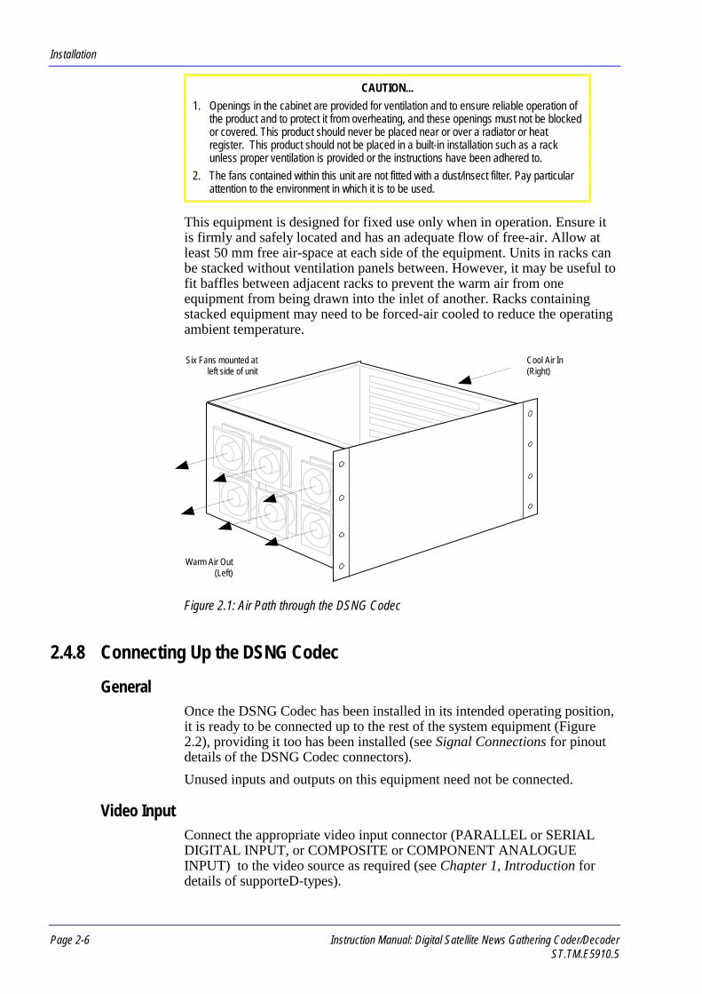
This equipment is designed for fixed use only when in operation. Ensure itis firmly and safely located and has an adequate flow of free-air. Allow atleast 50 mm free air-space at each side of the equipment. Units in racks canbe stacked without ventilation panels between. However, it may be useful tofit baffles between adjacent racks to prevent the warm air from oneequipment from being drawn into the inlet of another. Racks containingstacked equipment may need to be forced-air cooled to reduce the operatingambient temperature.
Figure 2.1: Air Path through the DSNG Codec
2.4.8 Connecting Up the DSNG Codec
GeneralOnce the DSNG Codec has been installed in its intended operating position,it is ready to be connected up to the rest of the system equipment (Figure2.2), providing it too has been installed (see Signal Connections for pinoutdetails of the DSNG Codec connectors).
Unused inputs and outputs on this equipment need not be connected.
Video InputConnect the appropriate video input connector (PARALLEL or SERIALDIGITAL INPUT, or COMPOSITE or COMPONENT ANALOGUEINPUT) to the video source as required (see Chapter 1, Introduction fordetails of supporteD-types).
Cool Air In(Right)
Six Fans mounted atleft side of unit
Warm Air Out(Left)

Installation
Instruction Manual: Digital Satellite News Gathering Coder/Decoder Page 2-7ST.TM.E5910.5
Audio InputsConnect the AUDIO INPUT A and AUDIO INPUT B, LEFT and RIGHTconnectors to the audio source as required (see Chapter 1, Introduction fordetails of supported modes).
Data InputsConnect the DATA INPUTS connectors to the data source as required forthe chosen mode of data/message transfer. One RS-422 synchronous datachannel and two RS-232 asynchronous data channels are provided.
Local / Remote ControlFor local control from the front panel, see Chapter 3, Local Control andOperation for details.
If control from a Remote Control Terminal is required, connect the terminalto the MULTIDROP RS-485/RS-422 connector on the Multiplexer /Baseband Modulator Card to configure the unit (see DSNG Codec RemoteControl Interface Specification ST.TS.E5910 for details).
A RESET/STATUS I/O connector provides a telemetry port.

Installation
Page 2-8 Instruction Manual: Digital Satellite News Gathering Coder/DecoderST.TM.E5910.5
Figure 2.2: Equipment Connectors
DIGITAL SATELLITE NEWS-GATHERING CODEC
IRD INPUTS
L-BAND
IF
TRANSPORT STREAM INPUT/DVBPARALLEL
ENCODER OUTPUT
IF OUTPUT (70/140MHz)
TRANSPORT STREAMOUTPUT/DVB PARALLEL
IF MONITOR 1
IF MONITOR 2 (IRD)
Main modulated QPSK output
Baseband CompressedMPEG-2 output
Modulated QPSK(70/140 MHz) output
Modulated QPSK(70/140 MHz) outputto IRD
ENCODER VIDEO INPUTS
PAL/NTSC-COMPOSITE
PARALLEL DIGITAL
SERIAL DIGITAL
YUV / BETACAMCOMPONENT
Choose any ONE video input
Two composite analogue outputs carrying the same video
One stereo or two mono outputs
Asynchronous datachannel
Synchronous dataA.C. Power
Audio channels(either mono or
stereo pair)
ENCODER AUDIO INPUTS
A LEFT/DIGITAL
A RIGHT
B LEFT/DIGITAL
B RIGHT
ENCODER DATA INPUTS
RS-422 (HIGH RATE)
RS-232-CH A (LOW RATE)
RS-232-CH B (LOW RATE)
Audio inputs(either mono or
stereo pair)
Synchronous datachannel
Asynchronousdata channel
Asynchronousdata channel
This connector can supply ad.c. voltage to an LNB
Modulated QPSK(70/140MHz) input
Baseband CompressedMPEG-2 input
CONTROL AND CONFIG
DOWNLOAD RS-232
REMOTE 1 RS-232
REMOTE 2 RS-232
MULTIDROP RS-485/RS-422
RESET/STATUS
IRD OUTPUTS
COMP VIDEO OUTPUT CH A
COMP VIDEO OUTPUT CH B
AUDIO L
AUDIO R
DATA OUTPUT RS-232
DATA OUTPUT RS-422
Software upgrades
Reserved
Software upgrades
Remote control I/F
Telemetry I/F
NOTE…IRD inputs / outputs only availableon M2/ESN/SNGB option only.
Installation
Instruction Manual: Digital Satellite News Gathering Coder/Decoder Page 2-9ST.TM.E5910.5
Transport Stream / IF OutputConnect either the baseband TRANSPORT STREAM OUTPUT or the IFOUTPUT, as required, to the output equipment.
Baseband / IF/ L-Band IRDConnect signals as required to the IRD Card, either baseband or IF (from theIF Modulator Card) or L-band.
Power SupplyThe following section (Mains Operating Voltage and Fusing) providesdetails regarding power supply fusing, earthing, connection and safety.Please read all instructions carefully and take note of all warnings andcautions.
2.5 Mains Operating Voltage and Fusing
2.5.1 AC Power Supply
2.5.2 AC Power Supply
CAUTION...
This product should be operated only from the type of ac power source indicated on themarking label. If you are not sure of the type of power supply to your installation, consult a
qualified electrical engineer or your local power company.
The power supply used in this equipment is a universal autosensing, a.c.power supply unit designed for use at either 100-120 V a.c. or 220-240 Va.c., 45-440 Hz (see Annex B, Technical Specification for a details). Thereare, therefore, no links or switches to be altered for operation from differenta.c. supplies.
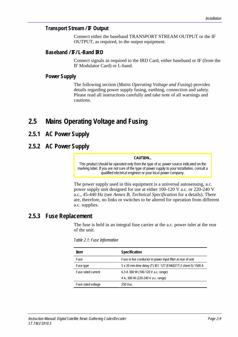
2.5.3 Fuse ReplacementThe fuse is held in an integral fuse carrier at the a.c. power inlet at the rearof the unit.
Table 2.1: Fuse Information
Item Specification
Fuse Fuse in live conductor in power input filter at rear of unit
Fuse type 5 x 20 mm time delay (T) IEC 127 (EN60217-2 sheet 5) 1500 A
Fuse rated current 6.3 A 300 W (100-120 V a.c. range)
4 A, 300 W (220-240 V a.c. range)
Fuse rated voltage 250 Vac.

Installation
Page 2-10 Instruction Manual: Digital Satellite News Gathering Coder/DecoderST.TM.E5910.5
To replace the a.c. power fuse:
WARNING…
BEFORE REPLACING THE REAR PANEL FUSE, DISCONNECT THE EQUIPMENTFROM THE SUPPLY. FAILURE TO DO THIS MAY EXPOSE HAZARDOUS VOLTAGES.
UNPLUG THE EQUIPMENT FROM THE LOCAL SUPPLY SOCKET.
1. Ensure that power is turned off and the power cable is disconnectedfrom the a.c. power inlet.
2. Ease out the fuse carrier by placing a thumbnail (a small, flat-bladedscrewdriver may be used) in the notch at the top of the carrier.
CAUTION...
When replacing the power input fuse, always ensure that you fit a fuse of the correct typeand rating, according to the intended operating voltage. Failure to do so will result in
inadequate protection.
3. Replace the fuse in the carrier at the side corresponding to the operatingvoltage to be used.
4. Insert the fuse carrier back in the a.c. power inlet. Ensure that theorientation of the fuse carrier is correct, according to the operatingvoltage to be used. The active fuse is on the right-hand side, whenviewed from the rear.
Figure 2.3: Orientation of Twin Fuse Carrier
If the replacement fuse also blows, do not continue. Disconnect theequipment and contact Customer support for advice.
2.5.4 Power Cable and EarthingCheck you have been given an a.c. power cable suitable for the country inwhich the equipment is to be used.
ON (I)/OFF(0)Rocker Switch
IO
A.C. Power Inlet
Twin-Fuse Carrier
The supply voltage is set to the valueshown when these two marks arealigned
If required, use a small flat-bladedscrewdriver in the notch at the top ofthe carrier to ease it out
200 - 240
The active fuse is on the right whenviewed from the rear panel

Installation
Instruction Manual: Digital Satellite News Gathering Coder/Decoder Page 2-11ST.TM.E5910.5
WARNINGS...
1. IF THE MOULDED PLUG FITTED TO THE MAINS CABLE SUPPLIED WITH THISEQUIPMENT IS NOT REQUIRED, PLEASE DISPOSE OF IT SAFELY. FAILURE TODO THIS MAY ENDANGER LIFE AS LIVE ENDS MAY BE EXPOSED IF THEREMOVED PLUG IS INSERTED INTO A MAINS OUTLET.
2. POWER-SUPPLY CORDS SHOULD BE ROUTED SO THAT THEY ARE NOTLIKELY TO BE WALKED ON OR PINCHED BY ITEMS PLACED UPON ORAGAINST THEM, PAYING PARTICULAR ATTENTION TO CORDS AT PLUGS,CONVENIENCE RECEPTACLES, AND THE POINT WHERE THEY EXIT FROM THEAPPLIANCE.
This equipment is supplied with a two metre detachable mains supply cablefitted with a moulded plug suitable for either the USA, UK or Europe.
The wires in the mains cable are coloured in accordance with the wirecolour code shown in Table 2.2 .
Table 2.2: Supply Cable Wiring Colours
UK(BS 1363)
EUROPE(CEE 7/7)
USA(NEMA 5-15P)
Earth: Green-and-yellow Green-and-yellow Green
Neutral: Blue Blue White
Live: Brown Brown Black
Functional / Protective Earth
WARNING...
1. THE EQUIPMENT MUST BE CORRECTLY EARTHED THROUGH MOULDED PLUGSUPPLIED WITH THE EQUIPMENT. IF THE LOCAL MAINS SUPPLY DOES NOTHAVE AN EARTH CONDUCTOR DO NOT CONNECT THE EQUIPMENT. CONTACTCUSTOMER SUPPORT FOR ADVICE.
2. THE PROTECTIVE EARTH IS CONNECTED TO THE FUNCTIONAL EARTHTERMINAL WITHIN THE UNIT. IF THE REAR PANEL TERMINAL IS LOOSE, DONOT POWER THE UNIT. CONTACT CUSTOMER SUPPORT FOR ADVICE.
3. BEFORE CONNECTING THE EQUIPMENT TO THE SUPPLY, CHECK THE SUPPLYREQUIREMENTS IN ANNEX B.
This equipment has a Functional Earth terminal located at the rear panel.This is not a Protective Earth for electric shock protection. Ensure that theterminal is clean and corrosion-free before connecting. The terminal isprovided to:
1. Ensure all equipment chassis fixed within a rack are at the same technicalearth potential. To do this, connect a wire between the functional earthterminal and a suitable point on the rack.
2. Eliminate the migration of stray charges when connecting betweenequipments.

Installation
Page 2-12 Instruction Manual: Digital Satellite News Gathering Coder/DecoderST.TM.E5910.5
Connecting the DSNG Codec
WARNING...
DO NOT OVERLOAD WALL OUTLETS AND EXTENSION CORDS AS THIS CANRESULT IN A RISK OF FIRE OR ELECTRIC SHOCK.
To connect the unit to the local a.c. power supply:
1. Ensure the local a.c. supply is switched OFF.
2. Ensure the a.c. power switch at the rear of the DSNG Codec is switchedOFF (0).
3. Ensure the correct fuse type and rating has been fitted to both theequipment (see Fuse Replacement) and the a.c. power cable.
4. Connect the a.c. power cable to the DSNG Codec power inlet connectorand then to the local power supply.
2.6 Signal Connections
2.6.1 GeneralAll signal input/output connectors are located at the rear panel of the DSNGCodec. For a detailed interface specification see Annex B, TechnicalSpecification.
Always use the specified cables supplied for signal integrity and compliancewith EMC requirements.
Figure 2.4: Rear Panel Connectors

Installation
Instruction Manual: Digital Satellite News Gathering Coder/Decoder Page 2-13ST.TM.E5910.5
2.6.2 Audio / Data ConnectorsRS-232 CH A
A 9-way, D-type female connectorprovides a low rate asynchronous,serial communications interface fortransmission of data.
Table 2.3: RS-232 Data Connector
Pin Signal Pin Signal
1 PROTECTIVE GROUND 4 NOT CONNECTED
2 TXD TRANSMIT DATA (O/P) 5 SYSTEM GROUND
3 RXD RECEIVE DATA (I/P) 6-9 NOT CONNECTED
RS-232 CH BA second asynchronous, serial communications interface connector,identical to that above (see RS-232 CH A).
RS-422A 15-way, D-type female connectorprovides a high-rate synchronous,serial communications interface fortransmission of data.
Table 2.4: RS-422 Data Connector
Pin Signal Pin Signal
1 PROTECTIVE GROUND 9 DATA-
2 DATA+ 10-13 NOT CONNECTED
3-6 NOT CONNECTED 14 CLKIN-
7 CLKIN+ 15 NOT CONNECTED
8 GROUND (0V)
Audio Input A (Left/Digital)An XLR female socket provides aninterface for an audio channel whichmay be used as a single analogue ordigital (AES/EBU) input, or may beconfigured as the left channel of astereo pair.
Table 2.5: Audio Input Connector
Pin Signal (Analogue) Signal (Digital)
1 X - CHASSIS GROUND X CHASSIS GROUND
2 L (LINE) - ANALOGUE AUDIO (+) L - DIGITAL AUDIO (+)
3 R (RETURN) - ANALOGUE AUDIO (-) R - DIGITAL AUDIO (-)
3
12
1
9
8
15
1
6
5
9

Installation
Page 2-14 Instruction Manual: Digital Satellite News Gathering Coder/DecoderST.TM.E5910.5
Audio Input A (Right)An XLR female socket provides an interface for an audio channel whichmay be used as a single analogue input, or may be configured as the rightchannel of a stereo pair.
Audio Input B (Left/Digital)A second pair of audio input connectors, identical to that above (see AUDIOINPUT A (LEFT/DIGITAL)).
Audio Input B (Right)A second pair of audio input connectors, identical to that above (see AUDIOINPUT A (RIGHT)).
2.6.3 Video Input Connectors
Digital Parallel InputA 25-way, D-type female connectorprovides a parallel digital video inputto the Encoder. The associated LED islit when this connector is in use.
Table 2.6: Digital Parallel Video Input Connector
Pin Signal Pin Signal
1 CLOCK A 14 CLOCK B
2 PROTECTIVE GROUND 15 PROTECTIVE GROUND
3 DATA 7A (MSB) 16 DATA 7A (MSB)
4 DATA 6A 17 DATA 6B
5 DATA 5A 18 DATA 5B
6 DATA 4A 19 DATA 4B
7 DATA 3A 20 DATA 3B
8 DATA 2A 21 DATA 2B
9 DATA 1A 22 DATA 1B
10 DATA 0A 23 DATA 0B
11 NOT CONNECTED 24 NOT CONNECTED
12 NOT CONNECTED 25 NOT CONNECTED
13 CABLE SHIELD
13 1
25 14

Installation
Instruction Manual: Digital Satellite News Gathering Coder/Decoder Page 2-15ST.TM.E5910.5
Digital Serial InputA 75 Ω BNC connector provides aserial digital video input to the unit.The associated LED is lit when thisconnector is in use.
Table 2.7: Digital Serial Video Input Connector
Pin Signal
CENTRE VIDEO INPUT
SCREEN GROUND
Composite Analogue InputA 75 Ω BNC socket provides adifferential analogue video input foreither a 625 line composite PAL-I/B/G/H or 525 line composite NTSC-M signal. The associated LED is litwhen this connector is in use. TheComposite connector doubles as theY component connector.
Table 2.8: Composite Video Input Connector
Pin Signal
CENTRE VIDEO INPUT
SCREEN GROUND
Component (Y, B-Y, R-Y) InputsThree 75 Ω BNC sockets provide aYUV component or Betacamcomponent analogue video input. Theassociated LEDs are lit when thisconnector is in use. The Y connectordoubles as the composite connector.
Table 2.9: Component Video Input Connectors
Pin Signal
CENTRE VIDEO INPUT
SCREEN GROUND

Installation
Page 2-16 Instruction Manual: Digital Satellite News Gathering Coder/DecoderST.TM.E5910.5
2.6.4 MPEG-2 Video Encoder ConnectorsDownload RS-232
A 9-way, D-type male connector is provided for debug purposes. Softwareupgrades are made via this connector.
2.6.5 Multiplexer / Baseband Modulator ConnectorsReset /Status
A 9-way, D-type female connectorprovides external indication of statusby relay contacts. Permits reset of theDSNG Codec by shorting twocontacts together.
Table 2.10: Reset / Status Connector
Pin Signal Pin Signal
1 PROTECTIVE GROUND 6 MAKE TO FAIL COMMONWHEN OK
2 FAIL (COMMON) 7 MAKE TO FAIL COMMONWHEN NOT OK
3 MAKE TO ALARM COMMON WHEN OK 8 ALARM COMMON
4 MAKE TO ALARM COMMON WHENNOT OK
9 RESET (LINE 1)
5 RESET (LINE 2) SHORTING PIN 5 TOPIN 9, CAUSES A SYSTEM RESET
Remote 1 RS-232A 9-way, D-type male connector is provided for future expansion.
Remote 2 RS-232A 9-way, D-type male connector is provided for debug purposes. Softwareupgrades are made via this connector.
Multidrop RS-485 / RS-422A 9-way, D-type female connector iswired to be compatible with RS-449(mechanical specification of RS-422).Provides remote control using RS-422or RS-485 type signalling.
Table 2.11: Multidrop RS-485 / RS-422 Data Connector
Pin Signal Pin Signal
1 PROTECTIVE GROUND 6 RX DATA B
2 RX READY 7 RTS
3 TX DATA A 8 CTS
4 RX DATA A 9 TX DATA B
5 GROUND (0V)
1
6
5
9
1
6
5
9

Installation
Instruction Manual: Digital Satellite News Gathering Coder/Decoder Page 2-17ST.TM.E5910.5
Transport Stream Output / DVB ParallelA DVB-LVDS, 25-way, D-typefemale connector is provided forthe transport data stream output.
Table 2.12: Transport Stream Output / DVB Parallel Connector (DVB-LVDS)
Pin Signal Pin Signal
1 CLOCK A 14 CLOCK B
2 SYSTEM_GROUND 15 SYSTEM_GROUND
3 DATA 7 A 16 DATA 7 B
4 DATA 6 A 17 DATA 6 B
5 DATA 5 A 18 DATA 5 B
6 DATA 4 A 19 DATA 4 B
7 DATA 3 A 20 DATA 3 B
8 DATA 2 A 21 DATA 2 B
9 DATA 1 A 22 DATA 1 B
10 DATA 0 A 23 DATA 0 B
11 DATA_VALID A 24 DATA_VALID B
12 PSYNC A 25 PSYNC B
13 CABLE_SHIELD
2.6.6 IF Modulator ConnectorsIF Output
A 75 Ω BNC female socket providesthe main QPSK (70/140 MHz)modulated output.
Table 2.13: IF Output Connector
Pin Signal
CENTRE IF OUTPUT
SCREEN GROUND
IF Monitor OutputTwo 75 Ω BNC female socketsprovide QPSK (70/140 MHz)modulated monitoring outputs. Socketnumber 2 is intended for connectionto the IRD Card IF Input.
Table 2.14: IF Monitor Output Connectors
Pin Signal
CENTRE IF OUTPUT
SCREEN GROUND
13 1
25 14

Installation
Page 2-18 Instruction Manual: Digital Satellite News Gathering Coder/DecoderST.TM.E5910.5
NOTE…
The power level on these outputs is fixed at -10 dBm and the output is always enabled.
2.6.7 IRD Connectors (M2/ESN/SNGB option only)
Data Output RS-232A 9-way, D-type female connectorprovides an asynchronous, serialcommunications output for the datachannel.
Table 2.15: Data Output RS-232 Connector
Pin Signal Pin Signal
1 PROTECTIVE GROUND 2 RXD RECEIVE DATA (O/P)
3 TXD TRANSMIT DATA (NOTUSED)
4 NOT CONNECTED
5 GND SYSTEM GROUND 6 NOT CONNECTED
7 RTS REQUEST TO SEND(NOT USED)
8 CTS CLEAR TO SEND (NOTUSED)
9 NOT CONNECTED
Composite Video OutputsTwo 75 Ω BNC female socketsprovide outputs for video. The singlevideo channel is split into twoidentical channels, A and B.
Table 2.16: Composite Video Output Connectors
Pin Signal
CENTRE VIDEO OUTPUT
SCREEN GROUND
Audio Outputs (L/R)Two 600 Ω XLR male sockets areused to output a single stereo channelof audio, or two mono channels. Leftand right signals are available onseparate output connectors.
Table 2.17: Audio Output Connector
Pin Signal
1 X - CHASSIS GROUND
2 L (LINE) - ANALOGUE AUDIO (+)
3 R (RETURN) - ANALOGUE AUDIO (-)
1
6
5
9
3
12
3
12

Installation
Instruction Manual: Digital Satellite News Gathering Coder/Decoder Page 2-19ST.TM.E5910.5
L-band InputA 75 Ω BNC female socket providesan input for an L-band (950-2050 MHz) QPSK modulated signal.This connector is also capable ofproviding a dc voltage supply foran LNB.
Table 2.18: L-band Input Connector
Pin Signal
CENTRE L-BAND INPUT
SCREEN GROUND
IF InputA 75 Ω BNC female sockets accept aQPSK (70/140 MHz) modulatedinput. Socket number 2 on the IFMonitor Card directly above isdedicated for connection to thisconnector.
Table 2.19: IF Input Connector
Pin Signal
CENTRE IF INPUT
SCREEN GROUND
Data Output RS-422A 15-way, D-type male connectorprovides a high-rate synchronousoutput for the data channel.
Table 2.20: Data Output RS-422 Connector
Pin Signal Pin Signal
1 PROTECTIVE GROUND 9 DATA-
2 DATA+ 10 DTR-
3 DTR+ 11 NOT CONNECTED
4 NOT CONNECTED 12 DSR-
5 DSR+ 13 NOT CONNECTED
6 NOT CONNECTED 14 CLOCK-
7 CLOCK+ 15 NOT CONNECTED
8 PROTECTIVE GROUND
1
9
8
15

Installation
Page 2-20 Instruction Manual: Digital Satellite News Gathering Coder/DecoderST.TM.E5910.5
Transport Stream Input / DVB ParallelA DVB-LVDS, 25-way, D-typefemale connector is provided forthe transport data stream input.
Table 2.21: Transport Stream Input / DVB Parallel Connector (DVB-LVDS)
Pin Signal Pin Signal
1 CLOCK A 14 CLOCK B
2 PROTECTIVE GROUND 15 PROTECTIVE GROUND
3 DATA 7 A 16 DATA 7 B
4 DATA 6 A 17 DATA 6 B
5 DATA 5 A 18 DATA 5 B
6 DATA 4 A 19 DATA 4 B
7 DATA 3 A 20 DATA 3 B
8 DATA 2 A 21 DATA 2 B
9 DATA 1 A 22 DATA 1 B
10 DATA 0 A 23 DATA 0 B
11 DATA_VALID A 24 DATA_VALID B
12 PSYNC A 25 PSYNC B
13 PROTECTIVE GROUND
13 1
25 14

Instruction Manual: Digital Satellite News Gathering Coder/Decoder Page 3-1ST.TM.E5910.5
Chapter 33. Local Control and Operation
Contents3.1 Introduction...................................................................3-3
3.1.1 Using Local Control ...........................................3-33.1.2 Using Remote Control .......................................3-3
3.2 Controls and Indicators.................................................3-33.2.1 LED Colour Coding Philosophy .........................3-33.2.2 Front Panel Controls and Indicators..................3-43.2.3 Rear Panel Controls and Indicators...................3-5
3.3 Getting Started .............................................................3-53.3.1 Choosing Parameters........................................3-53.3.2 Automatic Data Rate Selection..........................3-6
IF Operation ........................................................3-6Baseband Operation ...........................................3-7
3.3.3 Manual Data Rate Selection..............................3-73.3.4 Configuration File Loading and Storage............3-8
3.4 Powering Up/Down.......................................................3-93.4.1 Before Powering Up... .......................................3-93.4.2 Powering Up......................................................3-93.4.3 Powering Down ...............................................3-103.4.4 Quick Restart...................................................3-10
3.5 Navigating the Display Screens..................................3-103.5.1 Booting-up .......................................................3-103.5.2 Moving through the Screens ...........................3-113.5.3 Help Screens...................................................3-113.5.4 Idle Screen ......................................................3-11
3.6 Status Screens ...........................................................3-143.6.1 What is Status Mode? .....................................3-143.6.2 Status / System ...............................................3-153.6.3 Status / Modulator ...........................................3-153.6.4 Status / Mux ....................................................3-16
3.6.5 Status / Video.................................................. 3-173.6.6 Status / Audio.................................................. 3-183.6.7 Status / Data ................................................... 3-193.6.8 Status / Receiver............................................. 3-19
Status / Receiver / View Service Info................ 3-20Status / Receiver / View Video.......................... 3-20Status / Receiver / View Audio.......................... 3-20Status / Receiver / View Data ........................... 3-21Status / Receiver / View Input........................... 3-21Status / Receiver / View Tuner ......................... 3-21Status / Receiver / View Demodulator .............. 3-21
3.7 Setup Screens............................................................ 3-223.7.1 What is Setup Mode?...................................... 3-223.7.2 Setup / Load Stored Config............................. 3-223.7.3 Setup / Store Current Conf ............................. 3-233.7.4 Setup / Edit Config Title .................................. 3-233.7.5 Setup / Restor Orig Confgs............................. 3-243.7.6 Setup / Backup Configs................................... 3-243.7.7 Setup / System................................................ 3-26
Setup / System / Service Name ........................ 3-26Setup / System / Setup Remote Ctrl ................. 3-27Setup / System / Display Contrast .................... 3-28Setup / System / Set UTC Offset Hrs................ 3-29Setup / System / Set Time & Date .................... 3-29Setup / System / Alarm/Fail Relays .................. 3-29Setup / System / Keyboard Bleeper.................. 3-30Setup / System / Disable Setup/Diag................ 3-30Setup / System / Chnge Disable Pswd ............. 3-32
3.7.8 Setup / Modulator............................................ 3-33Setup / Modulator / IF Output............................ 3-33Setup / Modulator / IF Power ............................ 3-34
Local Control and Operation
Page 3-2 Instruction Manual: Digital Satellite News Gathering Coder/DecoderST.TM.E5910.5
Setup / Modulator / Modulation......................... 3-34Setup / Modulator / Tx Bandwidth..................... 3-34Setup / Modulator / Symbol Rate...................... 3-35Setup / Modulator / FEC Rate........................... 3-35Setup / Modulator / IF Frequency ..................... 3-36Setup / Modulator / Spectrum Inversion ........... 3-36Setup / Modulator / IF Preset Power................. 3-36Setup / Modulator / Sat Frequency (S5898Ver 2.3 and later) .............................................. 3-37Setup / Modulator / Sat Position (S5898 Ver2.3 and later)..................................................... 3-37Setup / Modulator / Sat Direction (S5898 Ver2.3 and later)..................................................... 3-37Setup / Modulator / Sat Polarisation (S5898Ver 2.3 and later) .............................................. 3-38
3.7.9 Setup / Mux (IF Output Selected) ................... 3-38Setup / Mux / Output Format ............................ 3-38Setup / Mux / Scramble .................................... 3-39Setup / Mux / Scramble Code........................... 3-39
3.7.10 Setup / Mux (Baseband Output Selected) ...... 3-39Setup / Mux / Output Format ............................ 3-40Setup / Mux / Mux Bit Rate ............................... 3-40Setup / Mux / Packet Length............................. 3-41Setup / Mux / RS Code (on/off)......................... 3-41Setup / Mux / Baseband Output........................ 3-41Setup / Mux / Scramble (on/off) ........................ 3-42Setup / Mux / Scramble Code........................... 3-42
3.7.11 Setup / Video .................................................. 3-42Setup / Video / Video Source............................ 3-42Setup / Video / Line Standard........................... 3-43Setup / Video / Pixel Resolution........................ 3-43Setup / Video / Video Bit Rate .......................... 3-44Setup / Video / Coding Mode............................ 3-44Setup / Video / Low Delay Mode ...................... 3-44Setup / Video / O/P on Video Loss ................... 3-45
3.7.12 Setup / Audio .................................................. 3-45Setup / Audio / Setup Channel A ...................... 3-46Setup / Audio / Setup Channel B ...................... 3-48Setup / Audio / Select Extra Lang..................... 3-48Setup / Audio / Add Lang Code ........................ 3-48Setup / Audio / Delete Language...................... 3-49Setup / Audio / Restore Orig Langs .................. 3-49
3.7.13 Setup / Data.................................................... 3-49Setup / Data / RS232 Channel A ...................... 3-50Setup / Data / RS232 Channel B ...................... 3-51Setup / Data / RS422 Channel ......................... 3-51
3.7.14 Setup / Receiver ............................................. 3-52Setup / Receiver / Receiver Mode .................... 3-52Setup / Receiver / Input Interface ..................... 3-52Setup / Receiver / Setup Tuner ........................ 3-53Setup / Receiver / Setup Demodulator ............. 3-54Setup / Receiver / Setup Service...................... 3-56
Setup / Receiver / Video Parameters ................3-58Setup / Receiver / Audio Parameters ................3-60Setup / Receiver / Scramble Code ....................3-60
3.8 Diagnostics Screens...................................................3-623.8.1 What is Diagnostics Mode?.............................3-623.8.2 Diagnostics / Alarms/Failures ..........................3-623.8.3 Diagnostics / Re-initialise DSNG .....................3-633.8.4 Diagnostics / Off-Line Diags............................3-63
Diagnostics / Off-Line Diags / Complete Self-Test ...................................................................3-63Diagnostics / Off-Line Diags / Modulator...........3-64Diagnostics / Off-Line Diags / Multiplexer(Mux) .................................................................3-64Diagnostics / Off-Line Diags / Video..................3-65Diagnostics / Off-Line Diags / Audio..................3-66Diagnostics / Off-Line Diags / Data ...................3-67Diagnostics / Off-Line Diags / Receiver.............3-67Diagnostics / Off-Line Diags / Front PanelDisply.................................................................3-68Diagnostics / Off-Line Diags / Keyboard ...........3-68Diagnostics / Off-Line Diags / Front PanelLEDs..................................................................3-69Diagnostics / Off-Line Diags / Alarm Relay .......3-69
List of TablesTable 3.1: Front Panel Controls and Indicators..............................3-4
List of IllustrationsFigure 3.1: Front Panel Controls and Indicators ............................3-4Figure 3.2: Data Rate Automatic Selection (IF Operation).............3-7Figure 3.3: Data Rate Automatic Selection (Baseband
Operation) .....................................................................3-7Figure 3.4: Data Rate Manual Selection ........................................3-7Figure 3.5: Configuration Loading and Storage .............................3-9Figure 3.6: Typical Boot-up Screens............................................3-10Figure 3.7: Help Screen ...............................................................3-11Figure 3.8: Idle Screen.................................................................3-11Figure 3.9: Display Screens Overview.........................................3-13Figure 3.10: Baseband Output Status Summary Screen .............3-14Figure 3.11: IF Output Status Summary Screen ..........................3-14Figure 3.12: Setup Screen ...........................................................3-22Figure 3.13: Diagnostics Screen ..................................................3-62
Local Control and Operation
Instruction Manual: Digital Satellite News Gathering Coder/Decoder Page 3-3ST.TM.E5910.5
3.1 Introduction3.1.1 Using Local Control
This chapter describes in detail, the Digital Satellite News GatheringCoder/Decoder controls, indicators and display screens, and the operationswhich may be performed using them. The display is ergonomicallydesigned, requiring only a few key presses to access the shallow hierarchy ofmenus, with only meaningful and relevant options displayed.If you are unfamiliar with this equipment a Getting Started guide is providedin this chapter to take you step-by-step through the setting up procedure.Once the equipment is set-up and running, there are normally no furtherOperator actions required, unless there is a requirement to change the set-upto accommodate a different configuration of input or output.
3.1.2 Using Remote ControlEverything which can be controlled and monitored at the front panel displaycan be accessed remotely by using a suitable protocol and set of NDS -proprietary remote commands via the rear panel remote control port (seeDSNG Codec Remote Control Interface Specification ST.TS.E5910).
3.2 Controls and Indicators3.2.1 LED Colour Coding Philosophy
There are three LED colours used in this equipment: Red is used to indicate fault conditions, e.g. a missing or faulty input
signal. For correct operation, all red LEDs must be off, although somemay be on briefly during power-up;
Yellow is used to indicate various system status conditions, e.g.Multiplexer occupancy. Thus, for normal operation, yellow LEDs maybe either on or off, or flashing;
Green is used to indicate correct conditions and correct systemfunctioning. For normal operation, all green LEDs must be oncontinuously.
This colour coding principle was devised to facilitate instant perception bythe Operator of the equipment operational status, i.e. any red LEDs on orgreen LEDs permanently off indicates a fault condition.
NOTE…If operating in Baseband mode, the red LEDs relating to the IF stage will be lit on theMuxMod Card S5898 and IRD Card S5902 (see Chapter 4, Equipment Description for adescription of the rear panel LEDs).

Local Control and Operation
Page 3-4 Instruction Manual: Digital Satellite News Gathering Coder/DecoderST.TM.E5910.5
3.2.2 Front Panel Controls and IndicatorsThe front panel (Figure 3.1) provides various keys and LEDs (Table 3.1).
Figure 3.1: Front Panel Controls and Indicators Table 3.1: Front Panel Controls and Indicators
Key / Indicator Description
Control LEDs:Live This green LED is lit when the equipment is “on-air”.
Local Control This yellow LED is lit when the unit is under local (front panel) control.
Remote Control This yellow LED is lit when the unit is under remote control.
Status LEDs:Alarm This red LED is lit when a failure of the equipment has been detected (accompanies triggering of the ALARM relay,
the contacts of which are available on the rear panel RESET / STATUS connector).
Power This green LED is lit when ac power is being received.
Mode Keys: NOTE…If Setup or Diagnostics are not selected, the unit is in Status mode.
Setup This key selects Setup mode and provides relevant options on the display for changing system setup parameters.The keys contain an integral green LED which is lit when the key is pressed.
Diagnostics This key selects Diagnostics mode and provides relevant options on the display for running system diagnostics.The keys contain an integral green LED which is lit when the key is pressed.
Keypad:0, 1, 2, 3, 4, 5, 6, 7, 8, 9, ., - These keys permit numerical input to be entered on some display pages to select options or enter parameter values.
Clear This key takes you back to the previous display, or cancels any changes to parameter values which have beenkeyed in but not yet entered.
Enter This key is used to select options and to confirm that changes made to parameter values are accepted.
Cursor Keys:< > ∧ ∨
These keys are used to move around the display pages and select menu options. The > key may duplicate thefunction of the Enter key, and the < key duplicate the Clear key on certain pages where these keys would serve noother useful purpose.
Function Keys:System, Modulator, Mux,Video, Audio, Data, Receiver
These keys select the functional areas of the unit and provide relevant options on the display, depending on whetherStatus, Setup or Diagnostics mode is selected. The keys contain an integral green LED which is lit when the key ispressed.

Local Control and Operation
Instruction Manual: Digital Satellite News Gathering Coder/Decoder Page 3-5ST.TM.E5910.5
3.2.3 Rear Panel Controls and IndicatorsLEDs on each of the cards which comprise the DSNG Codec are visible atthe rear panel of the unit. For normal operation, these LEDs are not needed.See Chapter 4, Equipment Description for a description of the on-cardLEDs.
3.3 Getting Started3.3.1 Choosing Parameters
The following check list provides a guide to getting the equipment up andrunning. It assumes that the equipment is to be operated locally using thefront panel display. However, the same sequence of events is also valid forremote operation.Familiarise yourself with the operating controls and indicators on the frontpanel of the unit (see Controls and Indicators). This will enable you to findyour way around the various display pages (see Navigating the DisplayScreens later in this chapter).1. Switch On the DSNG Codec.
With the DSNG Codec correctly installed, switch on the equipment inaccordance with the instructions given in Powering Up/Down. Confirmthat it powers up correctly. If it does not, refer to Chapter 6, FaultFinding.
2. Check Configuration.Check the Status screens to confirm whether the currently setparameters for each functional area (System, Modulator, Mux, Video,Audio, Data and Receiver) meet with your requirements. If they do,then the unit is ready for operation; switch on the audio and dataservices and turn on the video by selecting the input source.
If parameters need to be changed, proceed to next step. If not, proceedto step 4.
3. Change Configuration.If the required parameters are saved as a configuration file then load therelevant file (see Setup / Load Stored Config) and proceed to step 4. Ifnot:a) Set All Audio Parameters.
Enable audio channels, set the coding mode, input type, bit-rate,and all other parameters, as required. See Chapter 1, Introductionfor a table of the supported bit-rates which are dependent on chosenmode.
b) Set All Data Parameters.Enable data channels, set baud-rates, as required.
c) Select IF or Baseband Operation.Using the Setup / Mux / Output Format option, select the requiredoutput format (IF or Baseband). This enables access to the relevantModulator and/or Multiplexer parameters.

Local Control and Operation
Page 3-6 Instruction Manual: Digital Satellite News Gathering Coder/DecoderST.TM.E5910.5
d) Set Multiplexer Parameters.Select and modify the multiplexing parameters as required (bit-rate,packet length, RS encoding, scrambling). Video bit-rate and pixelresolution will be determined automatically to optimise the systemand fully utilise the baseband output bit-rate. By default thebaseband output will be on unless stored as off.
e) Set Modulator and Multiplexer Parameters.Select and modify the modulation parameters as required (IF outputpower, IF frequency, bandwidth, FEC rate, spectrum inversion).Symbol rate, video bit-rate and pixel resolution will be determinedautomatically to optimise the system and fully utilise the availablebandwidth. Set scrambling as required using the Setup / Muxscreen. By default the IF output will be off. Turn IF output andmodulation on when ready to transmit.
f) Check Video Bit-Rate and Resolution.These parameters will have been set automatically according to theselections made above. Check that the values set meet your needs.If not, you may make manual adjustments to reduce the audio anddata requirements to free up more bandwidth to allow higherresolution video to be processed.
g) Set Receiver Parameters.Check that the IRD is connected and set up to receive thetransmission.
NOTE…If manual changes are made to the configuration, and too low a bandwidth / symbol rateis entered for the required services, the display will offer the option to switch off theservices in the following order: Video, Audio B, Audio A, RS422, RS232 Ch A, RS232 ChB. Similarly when increasing bandwidth / symbol rate, the display offers the choice ofwhether to restore services or not.
4. Turn on the OutputTurn the output of the unit on to begin transmitting; Baseband output ison by default, IF Output is off by default. If using the IF output, turn onboth the modulation and the IF output.
3.3.2 Automatic Data Rate Selection
IF OperationThe starting point is usually to enter the bandwidth that has been allocatedfor use on the Satellite Transponder. Normally, the output symbol rate andthe video bit-rate are calculated automatically corresponding to the entry ofbandwidth and FEC rate parameters. In this way the DSNG Codec isoptimised and system capacity is not exceeded. This automated processtakes into account the data rates which have been allocated (manually) toaudio and data services. From the permissible bit-rate, the pixel resolution isselected automatically to maximise the quality of the video channel.

Local Control and Operation
Instruction Manual: Digital Satellite News Gathering Coder/Decoder Page 3-7ST.TM.E5910.5
Figure 3.2: Data Rate Automatic Selection (IF Operation)
Baseband OperationThe starting point is usually to enter the bit-rate and packet lengthrequirements of the telecommunications equipment. Normally, the video bit-rate is calculated automatically corresponding to the entry of theseparameters. In this way the DSNG Codec is optimised and system capacityis not exceeded. This automated process takes into account the data rateswhich have been allocated (manually) to audio and data services. From thepermissible bit-rate, the pixel resolution is selected automatically tomaximise the quality of the video channel.
Figure 3.3: Data Rate Automatic Selection (Baseband Operation)
3.3.3 Manual Data Rate SelectionAutomatic selections may, if required, be overridden to suit particularrequirements. The block diagram below (Figure 3.4) illustrates the generalprinciples and functions which are used in order to calculate the useful datarate which may then be allocated to the video, audio and data services.
Figure 3.4: Data Rate Manual Selection
EnterTx Bandwidth (or
Symbol Rate)FEC Rate
Audio ServicesData Services
Automaticallycalculates
Symbol Rate (orTx Bandwidth)Video Bit Rate
Automatically selectsPixel Resolution
EnterMux Bit Rate
Packet LengthAudio ServicesData Services
Automaticallycalculates
Video Bit Rate
Automatically selectsPixel Resolution
188 or 204 bytes in baseband
Baseband Output2-32 Mbit/s
IF Output1.5-16 MSym/s
Modulator
ConvolutionalFEC
Rates of 1/2, 2/3,3/4, 5/6, 7/8 maybe used
ModulationQPSK
Each symbolrepresents2 bits
Scaling factor ofapprox. 1.28
1 Video1.5-15 Mbit/s
Up to 4 Audio32-384 kbit/s
1 Data (Sync)64-1024 kbit/s
Up to 2 Data (Async)1200-9600 baud
CA/PSI & Overheadapprox. 400 kbit/s
(not selectable)
MPEGFormattingHeaders
184 bytes of dataconverts to 188
Multiplexer Packet Length
188 bytes of dataconverts to 204bytes(selectable)
RSEncoding
Coding expandsevery 188 bytesto 204
Pulse ShapingFilter
Scale factor of 1

Local Control and Operation
Page 3-8 Instruction Manual: Digital Satellite News Gathering Coder/DecoderST.TM.E5910.5
The ratio used for transponder bandwidth over symbol rate is approximately1.28. Therefore, the maximum useful data rate in IF output mode is:
BW x 1 x 2 x FEC x 188 x 184 Mbit/s
1.28 204 188
The maximum useful data rate in Baseband output mode, with RSencoding is:
mux rate x 188 x 184 Mbit/s
204 188
The maximum useful data rate in Baseband output mode, without RSencoding is:
mux rate x 184 Mbit/s
188
3.3.4 Configuration File Loading and StorageThe parameters currently in use may be stored and retrieved as desired toprevent having to re-enter all the corresponding values and settings everytime the unit is borrowed or temporarily changed to suit other requirements.
NOTE…The parameters currently in use are restored when the equipment is turned off and backon again, providing that the configuration has been stored - this happens automaticallywhen the user exits Setup mode.
Using the Setup / Store Current Conf option, the current configurationbeing used may be stored as a file for future use. Up to 16 suchconfigurations may be named and stored as files. Any of theseconfigurations may be loaded as the current configuration by using theSetup / Load Stored Config option. The configurations may be altered byusing the Setup / Edit Confg Title option.In addition, another set of 16 configurations may be stored and retrievedunder password protection using the Setup / Backup Configs option. Thisprevents unauthorised personnel from changing parameters which have beenoptimised for existing situations.The current set of user configurations may also be restored to the originalfactory defaults using the Setup / Restore Orig Confgs option (see Annex Cfor a complete listing of parameter values and settings for the defaultconfigurations).

Local Control and Operation
Instruction Manual: Digital Satellite News Gathering Coder/Decoder Page 3-9ST.TM.E5910.5
Figure 3.5: Configuration Loading and Storage
3.4 Powering Up/Down3.4.1 Before Powering Up...
Before powering up the DSNG Codec, check the following:1. The DSNG Codec enclosure has been properly installed in a suitable
location (see Chapter 2, Installation).2. The DSNG Codec has been connected to external equipment and power
supply, as required.
NOTE…All other connecting equipment, such as an up-converter, video source, etc., may beswitched on either before or after the DSNG Codec and will not result in damage, lock-up, or otherwise interfere with the operation of the DSNG Codec.
3. Power supply has been checked and a good earth provided.4. Ensure the correct fuse type and rating has been fitted to both the
equipment and the ac power cable.
3.4.2 Powering UpTo power up the DSNG Codec:1. Power up the DSNG Codec by setting the integral power switch at the
rear panel power inlet connector to on (I). The equipment will execute a series of power-up initialisation and self-
test routines which may take up to one minute.2. Confirm that power is available throughout the DSNG Codec, if not
refer to Chapter 5, Preventive Maintenance and Fault-finding:a) Front Panel Indicators - Confirm that the green Power LED is lit
and that the red Alarm LED is unlit.b) Rear Panel LEDs - At the rear panel, confirm that there are no
unexpected red LEDs lit, and that all green LEDs are lit (seeChapter 4, Equipment Description).
Backup Configs
16 Customer SpecificConfigurations
Editable Configs
16 Useable /Editable Configurations
Orig Configs
16 FactoryDefault Configurations
Current Config
Load
Restore defaultsStorage andRetrieval ispasswordprotected

Local Control and Operation
Page 3-10 Instruction Man
3. The unit may require a warm-up period of up to 10-15 minutes ifoperating at temperatures below 0°C. Stable operation withinspecification is normally available immediately.
3.4.3 Powering DownTo power down the DSNG Codec simply turn the power switch at the rearof the unit to off (0). The unit will shut down in a controlled manner.
3.4.4 Quick RestartThe DSNG Codec may be restarted from the Diagnostics / Re-initialiseDSNG screen. This provides a quick method of returning it to operationwithout powering down.
3.5 Navigating the Display Screens3.5.1 Booting-up
On power-up, the DSNG Codec runs through a boot-up sequence. Duringthis stage a Boot-up screen (Figure 3.6) is displayed until the equipment isre-initialised and firmware is loaded (accompanied by a bargraph to showthe percentage completed). On completion, the relevant “top-level” statusscreen (see Status Screens) is displayed according to the currently set outputformat (Baseband or IF), see Setup / Mux / Output Format.
D i g i t a l S N G C o d e c( A n y K e y = H E L P )
V 2 . 3 N D S
9 M H z , N T S C , 1 A u d i oB a s e b a n d 1 0 . 0 M b i t / s1 8 8 b y t e sC o n f i g u r i n g V i d e o
Figure 3.6: Typical Boot-up Screens
The display changes on completion of the boot-up sequence to show thecurrent set up.
ual: Digital Satellite News Gathering Coder/DecoderST.TM.E5910.5

Local Control and Operation
Instruction Manual: Digital Satellite News Gathering Coder/Decoder Page 3-11ST.TM.E5910.5
3.5.2 Moving through the ScreensScreens are available by pressing the required mode or function keys (seeFigure 3.9 overleaf). Most of the screens contain a menu of options or a listof parameters which may extend “below” the four-line display. These can beviewed by scrolling the page downward one line at a time using the cursorkeys (press and hold the cursor keys to move more quickly), or press thefunction key repeatedly to scroll down one screen at a time. Some menuoptions lead to a further menu screen in areas requiring many parameters tobe set to achieve complete control.Use the Clear key to step back through the screen levels, one at a time. Nomore than three presses are required to get back to the top-level Statusscreen from anywhere within the screen hierarchy. A message (StoringCurrent Configuration - Please Wait) may be displayed during the two orthree seconds that it takes to store the new configuration and re-display thestatus information.
3.5.3 Help ScreensHelp information is available on the front panel display by pressing theEnter key from the top-level Status page.
H E L P S c r e e n s∧∧∧∧ = P a g e U p∨∨∨∨ = P a g e D o w nC l e a r t o e x i t H e l p
Figure 3.7: Help Screen
18 pages of help text provide an overview of how to use the keys to navigatethe screens and make selections. Press Clear to restore the top-level Statusscreen. The Status screen is automatically restored if the Help screens areinactive, i.e. no keys are pressed, for a few seconds.
3.5.4 Idle ScreenIn the event that the equipment is inactive for a few minutes while in Statusor Setup mode, i.e. no keys are pressed, the equipment will assume that nofurther changes are required, and display a screen saver (Figure 3.4). If theequipment is in Diagnostics mode, the screen saver will not be activateduntil much longer (approximately 20 hours), since the user may be runningand monitoring tests. Press Clear to restore the top-level Status screen.
D S N G C o d e c
N D S
Figure 3.8: Idle Screen

Local Control and Operation
Page 3-12 Instruction Manual: Digital Satellite News Gathering Coder/DecoderST.TM.E5910.5
Top Level Screens Noneof the function keys (right)are selected
System Modulator Mux
Status
Status mode screensare displayed whenneither of the modekeys (below) areselected - press Clear
- The Service Name -Baseband 16.0Mbit/s204 bytes RS ONYUV 625 Audio On
or
- The Service Name -IF ON -27.0dBmMod ON BW 15.4MHzYUV 625 Audio On
Service Name- The Service nameConfig File Name1Control Local
Temp 38°CCooling Fan OnRemote Addr 49Disp Contrast 50%Lcl Time 10:22:23Lcl Date 23/11/1996Version 2.0Video FAIL/ALARMAudio A ALARM RlyAudio b ALARM RlyData ALARM RLYRx DeMod ALARM RlyRx Video ALARM RlyRx Audio ALARM RlyRx Data ALARM Rly
Tx Bandwidth15.360 MHz
Symbol Rate12.000 Msym/s
FEC Rate3/4
IF Frequency70.000 MHz
IF Output Power-27.0 dBm
IF OutputOff
ModulationOn
Spectrum InversionOff
Output FormatIF
ScrambleOff
or
Output FormatBaseband
Mux Bit Rate10.000 Mbit/s
Packet Length204
RS CodeOn
Baseband OutputOn
ScrambleOff
Setup Load Stored Config↑↑↑↑Store Current ConfEdit Config Title ↓↓↓↓
Select Option
Restor Orig ConfgsBackup ConfigsSystem ParametersSetup ModulatorSetup MuxSetup VideoSetup AudioSetup DataSetup ReceiverClose Screen
Service NameSetup Remote CtrlDisplay Contrast ↓↓↓↓
Select Option
Set UTC Offset HrsSet Time & DateAlarm/Fail RelaysKeyboard BleeperDisable Setup/DiagChnge Disable PswdClose Screen
IF Output (on/off)IF PowerModulation(on/off)↓↓↓↓Select Option
Tx BandwidthSymbol RateFEC RateIF FrequencySpectrum InversionIF Preset PowerSat FrequencySat PositionSat DirectionSat PolarisationClose Screen
Output FormatScramble (on/off)Scramble Code ↓↓↓↓Select Option
Close Screen
(IF Output Selected)
or
Save All ConfigsReload Backup CfgsChange Password ↓↓↓↓
Select Option
Close Screen
Local/Remote CtrlRemote Ctrl AddrssRmt Ctrl Baud Rate ↓↓↓↓
Select Option
No. of Data BitsNo. of Stop BitsClose Screen
Output FormatMux Bit RatePacket Length ↓↓↓↓Select Option
RS Code (on/off)Baseband OutputScramble (on/off)Scramble CodeClose Screen
(Baseband OutputSelected)
Diagnostics Alarms/FailuresRe-initialise DSNGOff-Line Diags ↓↓↓↓
Select Option
Close Screen
Complete Self-TestModulatorMultiplexer (Mux) ↓↓↓↓
Select Option
VideoAudioDataReceiverFront Panel DisplyKeyboardFront Panel LEDsAlarm RelayFail RelayClose Screen
(IF Output Selected onMux Setup menu)
or
IF Not Enabled
*Output FormatBASEBAND
(Baseband, IF)
(Baseband OutputSelected on Mux
Setup Menu)
S58898 Version 2.3 and later.

Local Control and Operation
Instruction Manual: Digital Satellite News Gathering Coder/Decoder Page 3-13ST.TM.E5910.5
Video Audio Data Receiver
Video SourceYUV
Line Standard625
Pixel ResolutionAUTO - 544
Video Bit RateAUTO - 13.630 Mbit/sCoding Mode
IBBPLow Delay Mode
OffO/P On Video Loss
Freeze FrameVideo PID
0x134
Channel A:On
Ch A Coding ModeStereo
Channel A Type600 Ohms
Channel A Bit Rate384 kbit/s
Ch A LanguageEnglish
Ch A Level (L-R)
Ch A PID0x100
Channel B:On
Ch B Coding ModeDual Mono
Channel B Type20 kOhms
Channel B Bit Rate384 kbit/s
Ch B Language (L)English
Ch B Language (R)English
Ch B Level (L-R)
Channel B PID0x101
RS232 Channel A:On
RS232 ChA Baud Rate9600 baud
RS232 Ch1 PID0x102
RS232 Channel B:Off
RS232 ChB Baud Rate19200 baud
RS232 ChB PID0x103
RS422 Channel:On
RS422 Bit Rate448 kbits/s
RS422 PID0x104
View Service InfoView VideoView Audio
Select Option
View DataView InputView TunerView DemodulatorClose Screen
Status
Status mode screensare displayed whenneither of the modekeys (below) areselected - press Clear
Video SourceLine StandardPixel Resolution ↓↓↓↓Select Option
Video Bit RateCoding ModeLow Delay ModeO/P on Video LossClose Screen
Setup Channel ASetup Channel BSelect Extra Lang ↓↓↓↓Select Option
Add Lang CodeDelete LanguageRestore Orig LangsClose Screen
RS232 Channel ARS232 Channel BRS422 Channel↓↓↓↓
Select Option
Close Screen
Receiver ModeInput InterfaceSetup Tuner
Select Option
Setup DemodulatorSetup ServiceVideo ParametersAudio ParametersScramble CodeClose Screen
Setup
Ch A (on/mute/tone)Ch A Coding ModeCh A Type ↓↓↓↓Select Option
Ch A Bit RateCh A LanguageCh A View LevelsClose Screen
A similar menu screen isavailable forSetup Channel B
RS232 Ch A (on/off)ChA Baud RateClose Screen
Select Option
A similar menu screen isavailable forRS232 Ch B and RS422Channel
Figure 3.9: Display Screens Overview
Further Screens
Further Screens

Local Control and Operation
Page 3-14 Instruction Manual: Digital Satellite News Gathering Coder/DecoderST.TM.E5910.5
3.6 Status Screens3.6.1 What is Status Mode?
When the mode select keys (Setup and Diagnostics) are inactive, i.e. thegreen LED associated with each key is unlit, the unit is in Status mode.In this mode, status information is displayed on the front panel display,according to the function selected by pressing the System, Modulator,Mux, Video, Audio, Data or Receiver keys. If no keys are pressed, a statussummary screen is displayed showing the current mode of operation: eitherBaseband or IF output. Typical displays are shown below
- T h e S e r v i c e N a m e -B a s e b a n d 1 6 . 0 M b i t / s2 0 4 b y t e s R S O NY U V 6 2 5 A u d i o O n
Figure 3.10: Baseband Output Status Summary Screen
- T h e S e r v i c e N a m e -I F O N - 1 5 . 0 d B mM o d O N B W 9 . 0 M H zY U V 6 2 5 A u d i o O n
Figure 3.11: IF Output Status Summary Screen
Status screens may not be changed directly as they provide a read-onlydisplay of the parameters which have been set using the Setup screens.
Multiplexer Output Bit Rate Reed Solomon Error Correction Audio Services Enabled
IF Modulator Output Power Bandwidth Audio Services Enabled
Output Format
Packet Length
Video Input Source
Output Format
Modulation Enabled
Video Input Source
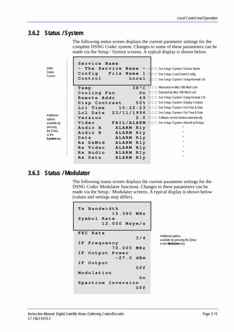
Local Control and Operation
Instruction Manual: Digital Satellite News Gathering Coder/Decoder Page 3-15ST.TM.E5910.5
3.6.2 Status / SystemThe following status screen displays the current parameter settings for thecomplete DSNG Codec system. Changes to some of these parameters can bemade via the Setup / System screens. A typical display is shown below.
S e r v i c e N a m e- T h e S e r v i c e N a m e -C o n f i g F i l e N a m e 1C o n t r o l L o c a l
T e m p 3 8 ° CC o o l i n g F a n O nR e m o t e A d d r 4 9D i s p C o n t r a s t 5 0 %L c l T i m e 1 0 : 2 2 : 2 3L c l D a t e 2 3 / 1 1 / 1 9 9 6V e r s i o n 2 . 0V i d e o F A I L / A L A R MA u d i o A A L A R M R l yA u d i o B A L A R M R l yD a t a A L A R M R l yR x D e M o d A L A R M R l yR x V i d e o A L A R M R l yR x A u d i o A L A R M R l yR x D a t a A L A R M R l y
3.6.3 Status / ModulatorThe following status screen displays the current parameter settings for theDSNG Codec Modulator functions. Changes to these parameters can bemade via the Setup / Modulator screens. A typical display is shown below(values and settings may differ).
T x B a n d w i d t h1 5 . 3 6 0 M H z
S y m b o l R a t e1 2 . 0 0 0 M s y m / s
F E C R a t e3 / 4
I F F r e q u e n c y7 0 . 0 0 0 M H z
I F O u t p u t P o w e r- 2 7 . 0 d B m
I F O u t p u tO f f
M o d u l a t i o nO n
S p e c t r u m I n v e r s i o nO f f
See Setup / System / Service Name See Setup / Load Stored Config See Setup / System / Setup Remote Ctrl
Measured on Mux / BB Mod Card Detected by Mux / BB Mod Card See Setup / System / Setup Remote Ctrl See Setup / System / Display Contrast See Setup / System / Set Time & Date See Setup / System / Set Time & Date Software version loaded automatically See Setup / System / Alarm/Fail Relays
“““““““
Additional optionsavailable by pressing the ∨∨∨∨ keyor the Modulator key
Initial Status Screen
Additional options available by pressing the ∨∨∨∨ key or the System key

Local Control and Operation
Page 3-16 Instruction Manual: Digital Satellite News Gathering Coder/DecoderST.TM.E5910.5
NOTE…In order to display the Status / Modulator screen (shown above), the output format of theMultiplexer must be set to IF (as opposed to Baseband) on the Setup / Mux / OutputFormat screen. If the IF output is not enabled, an advisory message is displayed:Baseband output currently enabled.
3.6.4 Status / MuxThe following status screen displays the current parameter settings for theDSNG Codec Multiplexer functions. Changes to these parameters can bemade via the Setup / Mux screens.With the output mode set to IF, a typical display is shown below (values andsettings may differ).
O u t p u t F o r m a tI F
S c r a m b l e ( o n / o f f )O f f
With the output mode set to Baseband, a typical display is shown below(values and settings may differ).
O u t p u t F o r m a tB a s e b a n d
M u x B i t R a t e1 0 . 0 0 0 M b i t / s
P a c k e t L e n g t h2 0 4
R S C o d eO n
B a s e b a n d O u t p u tO n
S c r a m b l eO f f
NOTE…If 188 byte packet length is selected then RS code (on/off) option is not displayed andcan only be off.
Additional optionsavailable by pressing the ∨∨∨∨ keyor the Mux keyOnly displayed if 204 byte
packets are set

Local Control and Operation
Instruction Manual: Digital Satellite News Gathering Coder/Decoder Page 3-17ST.TM.E5910.5
3.6.5 Status / VideoThe following status screen displays the current parameter settings for theDSNG Codec Video functions. Changes to these parameters can be madevia the Setup / Video screens. A typical display is shown below (values andsettings may differ).
V i d e o S o u r c eY U V
L i n e S t a n d a r d6 2 5
P i x e l R e s o l u t i o nA U T O - 5 4 4
V i d e o B i t R a t eA U T O - 1 3 . 6 3 0 M b i t / sC o d i n g M o d e
I B B PL o w D e l a y M o d e
O f fO ? P O n V i d e o L o s s
F r e e z e F r a m eV i d e o P I D
0 x 1 3 4
NOTE…If Video Source is set to Off then Video Bit Rate is not displayed.
Additional optionsavailable by pressing the ∨∨∨∨ keyor the Video key

Local Control and Operation
Page 3-18 Instruction Manual: Digital Satellite News Gathering Coder/DecoderST.TM.E5910.5
3.6.6 Status / AudioThe following status screen displays the current parameter settings for theDSNG Codec Audio functions. Changes to these parameters can be madevia the Setup / Audio screens. A typical display is shown below (values andsettings may differ).
C h a n n e l A :O n
C h A C o d i n g M o d eS t e r e o
C h a n n e l A T y p e6 0 0 O h m s
C h a n n e l A B i t R a t e3 8 4 k b i t / s
C h A L a n g u a g eE n g l i s h
C h A L e v e l ( L - R )
C h A P I D0 x 1 0 0
C h a n n e l B :O n
C h B C o d i n g M o d eD u a l M o n o
C h a n n e l B T y p e2 0 k O h m s
C h a n n e l B B i t R a t e3 8 4 k b i t / s
C h B L a n g u a g e ( L )E n g l i s h
C h B L a n g u a g e ( R )E n g l i s h
C h B L e v e l ( L - R )
C h a n n e l B P I D0 x 1 0 1
NOTE…If Channel A: (or B:) is set to Mute or Test Tone then Bit Rate information is notdisplayed. Bit rate is set to 64 kbit/s and is not user configurable.
Additional optionsavailable by pressing the ∨∨∨∨ keyor the Audio key
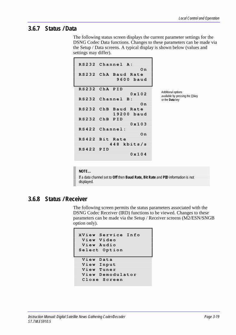
Local Control and Operation
Instruction Manual: Digital Satellite News Gathering Coder/Decoder Page 3-19ST.TM.E5910.5
3.6.7 Status / DataThe following status screen displays the current parameter settings for theDSNG Codec Data functions. Changes to these parameters can be made viathe Setup / Data screens. A typical display is shown below (values andsettings may differ).
R S 2 3 2 C h a n n e l A :O n
R S 2 3 2 C h A B a u d R a t e9 6 0 0 b a u d
R S 2 3 2 C h A P I D0 x 1 0 2
R S 2 3 2 C h a n n e l B :O n
R S 2 3 2 C h B B a u d R a t e1 9 2 0 0 b a u d
R S 2 3 2 C h B P I D0 x 1 0 3
R S 4 2 2 C h a n n e l :O n
R S 4 2 2 B i t R a t e4 4 8 k b i t s / s
R S 4 2 2 P I D0 x 1 0 4
NOTE…If a data channel set to Off then Baud Rate, Bit Rate and PID information is notdisplayed.
3.6.8 Status / ReceiverThe following screen permits the status parameters associated with theDSNG Codec Receiver (IRD) functions to be viewed. Changes to theseparameters can be made via the Setup / Receiver screens (M2/ESN/SNGBoption only).
V i e w S e r v i c e I n f oV i e w V i d e oV i e w A u d i o
S e l e c t O p t i o n
V i e w D a t aV i e w I n p u tV i e w T u n e rV i e w D e m o d u l a t o rC l o s e S c r e e n
Additional optionsavailable by pressing the ∨∨∨∨ keyor the Data key

Local Control and Operation
Page 3-20 Instruction Manual: Digital Satellite News Gathering Coder/DecoderST.TM.E5910.5
Status / Receiver / View Service InfoThe following status screen displays Receiver service information. A typicaldisplay is shown below (values and settings may differ).
N e t w o r k N a m eN D S - D S N G C o d e c
S e r v i c e N a m e9 M H z , P A L , 2 A u d i o
T r a n s p o r t S t r e a m0 x 0 0 0 1
N e t w o r k I D0 x F F F F
Status / Receiver / View VideoThe following status screen displays Receiver video settings. A typicaldisplay is shown below (values and settings may differ).
V i d e o P I D0 x 0 1 3 4
V i d e o B i t R a t e1 1 . 1 4 0 M b i t / s
V i d e o P i x e l R e s .5 4 4 x 5 7 6
Status / Receiver / View AudioThe following status screen displays Receiver audio settings. A typicaldisplay is shown below (values and settings may differ).
A u d i o P I D0 x 0 1 0 0
L a n g u a g eE n g l i s h
A u d i o R o u t i n gS t e r e o L > L , R > R
A u d i o G a i n+ 1 8 d B
Additional optionsavailable by pressing the ∨∨∨∨ keyor the Receiver key
Additional optionsavailable by pressing the ∨∨∨∨ keyor the Receiver key
Additional optionsavailable by pressing the ∨∨∨∨ keyor the Receiver key

Local Control and Operation
Instruction Manual: Digital Satellite News Gathering Coder/Decoder Page 3-21ST.TM.E5910.5
Status / Receiver / View DataThe following status screen displays Receiver data settings. A typicaldisplay is shown below (values and settings may differ).
R S 2 3 2 D a t a S t r e a m0 x 0 1 0 2
R S 4 2 2 D a t a S t r e a m0 x 0 1 0 4
Status / Receiver / View InputThe following status screen displays Receiver input mode. A typical displayis shown below (values and settings may differ).
O p e r a t i n g M o d eT r a c k i n g
I n p u t I n t e r f a c eI n t e r n a l
Status / Receiver / View TunerThe following status screen displays Receiver tuner settings. A typicaldisplay is shown below (values and settings may differ).
C a r r i e r F r e q u e n c y1 1 . 0 7 0 0 0 0 G H z
L N B L O F r e q u e n c y1 0 . 0 0 0 0 0 0 G H z
P o l a r i s a t i o nH o r i z o n a l
L N B P o w e rO f f
S p e c t r u m I n v e r s i o nO f f
Status / Receiver / View DemodulatorThe following status screen displays Receiver Demodulator settings. Atypical display is shown below (values and settings may differ).
D e m o d S t a t u sL o c k e d
S y m b o l R a t e9 . 0 0 0 M s y m / s
F E C R a t e3 / 4
S i g n a l L e v e l1 3 0
B E R1 e - 5
Additional optionsavailable by pressing the ∨∨∨∨ keyor the Receiver key
Additional optionsavailable by pressing the ∨∨∨∨ keyor the Receiver key

Local Control and Operation
Page 3-22 Instruction Manual: Digital Satellite News Gathering Coder/DecoderST.TM.E5910.5
3.7 Setup Screens3.7.1 What is Setup Mode?
Press the Setup key to enter Setup mode; the green LED associated with thekey will be lit.
NOTE…You must exit Diagnostics mode before you can enter Setup mode. Press Clear.
In this mode, setup information is displayed on the front panel display,according to the function selected by pressing the System, Modulator,Mux, Video, Audio, Data or Receiver keys. If no keys are pressed, a toplevel setup screen invites the user to choose one of these functional areas, orenables a configuration file to be loaded, stored, edited, etc.
L o a d S t o r e d C o n f i g ↑↑↑↑S t o r e C u r r e n t C o n fE d i t C o n f i g T i t l e ↓↓↓↓
S e l e c t O p t i o n
R e s t o r O r i g C o n f g sB a c k u p C o n f i g sS y s t e m P a r a m e t e r sS e t u p M o d u l a t o rS e t u p M u xS e t u p V i d e oS e t u p A u d i oS e t u p D a t aS e t u p R e c e i v e rC l o s e S c r e e n
Figure 3.12: Setup Screen
Choose a menu option by using the cursor keys to position the asteriskalongside the required option. Then press the Enter key to confirmselection. Depending on the option selected, either a parameter setup screenor a further list of options will be displayed (see the following headings).Choose the Close Screen option (or press the Clear key) to go back to thetop level Status screen.
3.7.2 Setup / Load Stored ConfigThe following setup screen permits a previously stored system configuration(containing all the parameter values and settings which may be entered atthe front panel display, except for parameters connected with the physicalunit, such as display contrast, keyboard bleeper, etc.) to be loaded, ready tobe used.
Up arrow only appears whenscrolling to indicate that there areoptions above
Additional options available by pressing the ∨∨∨∨ key
Down arrow indicates that thereare options below
Asterisk is moved by cursorkeys to indicate which line is
selected
Non moving user instructions

Local Control and Operation
Instruction Manual: Digital Satellite News Gathering Coder/Decoder Page 3-23ST.TM.E5910.5
F i l e N a m e 1F i l e N a m e 2F i l e N a m e 3 ↓↓↓↓
S e l e c t O p t i o n
F i l e N a m e 4
F i l e N a m e 1 6C l o s e S c r e e n
Up to 16 different configuration files may be stored. The names of thesefiles may be set by the user when they are stored (see Store Current Conf) oredited afterward (see Edit Confg Title). When a new configuration is loaded,it may take a few seconds to reconfigure the machine. During this timemessages may be displayed such as, Re-initialising DSNG, Please wait,and Re-initialising Video Encoder.
3.7.3 Setup / Store Current ConfThe following setup screen allows you to save the current systemconfiguration (containing all the parameter values and settings which maybe entered at the front panel display, except for parameters connected withthe physical unit, such as display contrast, keyboard bleeper, etc.) as aconfiguration file, and to give the file a 12 character name, to recall theconfiguration at a later date.
R e n a m e C o n f i gF i l e N a m e 1
C L E A R = N oE N T E R = Y e s
Press the Enter key to confirm storage.
3.7.4 Setup / Edit Config TitleThe following setup screen allows you to change the name of the 16configuration files.
E d i t C u r r e n t T i t l eE d i t F i l e N a m e 1E d i t F i l e N a m e 2
S e l e c t O p t i o n
E d i t F i l e N a m e 3
E d i t F i l e N a m e 1 6C l o s e S c r e e n

Local Control and Operation
Page 3-24 Instruction Manual: Digital Satellite News Gathering Coder/DecoderST.TM.E5910.5
Use the ∧∧∧∧ and ∨∨∨∨ cursor keys to increment or decrement through analphanumeric list. The numeric keypad may be used to enter numbersdirectly and the function keys may be used to enter the alphabeticalcharacters: S, M, M, V, A, D, R. Use the < and > cursor keys to move backand forth along the file name in order to enter the correct letter or number inthe appropriate place. Press the Enter key to confirm selection.When entered, a message is displayed, Storing new title, please wait(accompanied by a bargraph to show the percentage completed).
3.7.5 Setup / Restor Orig ConfgsThe following setup screen allows you to restore the factory-set defaultconfigurations and erase all 16 currently editable configuration files (seeAnnex C for a complete listing of parameter values and settings for thedefault configurations).
T h i s w i l l e r a s e A L LC o n f i g s . C O N T I N U E ?C L E A R = e x i tE N T E R = c o n f i r m
Press the Enter key to confirm deletion.
3.7.6 Setup / Backup ConfigsThe following setup screen allows you to save or reload a backup set of 16configuration files under password protection, in order that customer definedconfigurations can be safely stored while the equipment is temporarilyborrowed.
S a v e A l l C o n f i g sR e l o a d B a c k u p C f g sC h a n g e P a s s w o r d
S e l e c t O p t i o n
C l o s e S c r e e n
Choose a menu option by using the cursor keys to position the asteriskalongside the required option. Then press the Enter key to confirmselection. A setup screen will be displayed (see the following headings).Choose the Close Screen option (or press the Clear key) to go back to theSetup screen.
Setup / Backup Configs / Save All ConfigsThe following setup screen allows you to save the currently editable set of16 configuration files by overwriting the backup files. This process willtherefore erase the present set of backup configuration files.
T h i s w i l l e r a s e A L LB a c k u p R A M c o n f i g sC L E A R = E x i tE N T E R = C o n t i n u e ?

Local Control and Operation
Instruction Manual: Digital Satellite News Gathering Coder/Decoder Page 3-25ST.TM.E5910.5
Press the Enter key to continue.This action is protected by a password.
IMPORTANT NOTE…The equipment is supplied with password set to PASSWORD_ _ _ _. It is recommendedthat you change this immediately WHETHER YOU INTEND TO USE THIS FEATUREOR NOT. This will ensure that you are not locked out of the equipment either byaccident, or deliberately by someone else entering their own password.
E n t e r P a s s w o r d :_ _ _ _ _ _ _ _ _ _ _ _
U s e < > , C l e a r , E n t e r
A password of up to 12 characters must be entered before the 16configurations can be stored. Use the ∧∧∧∧ and ∨∨∨∨ cursor keys to increment ordecrement through an alphanumeric list. The numeric keypad may be usedto enter numbers directly and the function keys may be used to enter thealphabetical characters: S, M, M, V, A, D, R. Use the < and > cursor keys tomove back and forth along the password in order to enter the correct letter ornumber in the appropriate place.
NOTE…Passwords are case sensitive. Make sure you enter UPPER and lower case characterscorrectly.
TIP…The quickest way to enter “PASSWORD_ _ _ _” is to type in MASSVMRD by pressingthe appropriate function keys, and then to use the cursor keys to go back and change theM to a P, the V to a W, and the other M to an O, to produce PASSWORD.
Press Clear to return to the Setup / Backup Configs screen.
Setup / Backup Configs / Reload Backup CfgsThe following setup screen allows you to reload the backed-up set of 16customer defined configuration files which were previously stored underpassword protection.
Setup / Backup Configs / Change PasswordThe following setup screen allows you to change the password associatedwith Backup configurations.
C u r r e n t P a s s w o r d_ _ _ _ _ _ _ _ _ _ _ _
U s e < > , C l e a r , E n t e r
∧∧∧∧∨∨∨∨
∧∧∧∧∨∨∨∨

Local Control and Operation
Page 3-26 Instruction Manual: Digital Satellite News Gathering Coder/DecoderST.TM.E5910.5
Use the ∧∧∧∧ and ∨∨∨∨ cursor keys to increment or decrement through analphanumeric list. The numeric keypad may be used to enter numbersdirectly and the function keys may be used to enter the alphabeticalcharacters: S, M, M, V, A, D, R. Use the < and > cursor keys to move backand forth along the password in order to enter the correct letter or number inthe appropriate place.
NOTE…Passwords are case sensitive. Make sure you enter UPPER and lower case characterscorrectly.
TIP…The quickest way to enter “PASSWORD_ _ _ _” is to type in MASSVMRD by pressingthe appropriate function keys, and then to use the cursor keys to go back and change theM to a P, the V to a W, and the other M to an O, to produce PASSWORD.
3.7.7 Setup / SystemThe following setup screen permits changes to be made to the currentparameter settings for the overall DSNG Codec system.
S e r v i c e N a m eS e t u p R e m o t e C t r lD i s p l a y C o n t r a s t ↓↓↓↓
S e l e c t O p t i o n
S e t U T C O f f s e t H r sS e t T i m e & D a t eA l a r m / F a i l R e l a y sK e y b o a r d B l e e p e rD i s a b l e S e t u p / D i a gC h n g e D i s a b l e P s w dC l o s e S c r e e n
Choose a menu option by using the cursor keys to position the asteriskalongside the required option. Then press the Enter key to confirmselection. Depending on the option selected, either a parameter setup screenor a further list of options will be displayed (see the following headings).Choose the Close Screen option (or press the Clear key) to go back to thetop level Setup screen.
Setup / System / Service NameThe following setup screen permits a 20-character alphanumeric servicename to be entered.
S e r v i c e N a m e- T h e S e r v i c e N a m e -
U s e < > , C l e a r , E n t e r∧∧∧∧∨∨∨∨
← New Service Name entered here

Local Control and Operation
Instruction Manual: Digital Satellite News Gathering Coder/Decoder Page 3-27ST.TM.E5910.5
Use the ∧∧∧∧ and ∨∨∨∨ cursor keys to increment or decrement through analphanumeric list. The numeric keypad may be used to enter numbersdirectly and the function keys may be used to enter the alphabeticalcharacters: S, M, M, V, A, D, R. Use the < and > cursor keys to move backand forth along the name in order to enter the correct letter or number in theappropriate place.
Setup / System / Setup Remote CtrlThe following setup screen permits the interface parameters of the remotecontrol port to be set.
L o c a l / R e m o t e C t r lR e m o t e C t r l A d d r s sR m t C t r l B a u d R a t e ↓↓↓↓
S e l e c t O p t i o n
N o . o f D a t a B i t sP a r i t yN o . o f S t o p B i t sC l o s e S c r e e n
Choose a menu option by using the cursor keys to position the asteriskalongside the required option. Then press the Enter key to confirmselection. A parameter setup screen will be displayed (see the followingheadings).Choose the Close Screen option (or press the Clear key) to go back to theSetup / System screen.
Setup / System / Setup Remote Ctrl / Local/Remote CtrlThe following setup screen permits the control mode to be selected.
C o n t r o lL O C A L
( L o c a l , R e m o t e )U s e , C l e a r , E n t e r
Use the ∧∧∧∧ and ∨∨∨∨ cursor keys to select the required control mode option(Local or Remote). Press the Enter key to confirm selection.
Setup / System / Setup Remote Ctrl / Remote Ctrl AddrssThe following setup screen permits the address of the DSNG Codec to bespecified. This enables a single remote controller to control and monitorseveral units in a multidrop system.
R e m o t e C t r l A d d r s s4 9
U s e , C l e a r , E n t e r
∧∧∧∧∨∨∨∨
∧∧∧∧∨∨∨∨

Local Control and Operation
Page 3-28 Instruction Manual: Digital Satellite News Gathering Coder/DecoderST.TM.E5910.5
Use the ∧∧∧∧ and ∨∨∨∨ cursor keys, or use the numeric keypad, to select an addressin the available range (49 to 111). Press the Enter key to confirm selection.
Setup / System / Setup Remote Ctrl / Rmt Ctrl Baud RateThe following setup screen permits the baud rate of the remote controlinterface to be specified.
R m t C t r l B a u d R a t e1 9 2 0 0 b a u d
( 5 o p t i o n s )U s e , C l e a r , E n t e r
Use the ∧∧∧∧ and ∨∨∨∨ cursor keys, or use the numeric keypad, to select one of thebaud rate options (1200, 2400, 4800, 9600 or 19200). Press the Enter key toconfirm selection.
Setup / System / Setup Remote Ctrl / No. of Data BitsThe following setup screen permits the number of data bits in each frame ofdata to be specified for transmission over the remote control interface.
N o . o f D a t a B i t s8
( 7 , 8 )U s e , C l e a r , E n t e r
Use the ∧∧∧∧ and ∨∨∨∨ cursor keys, or use the numeric keypad, to select one of theavailable options (7 or 8). Press the Enter key to confirm selection.
Setup / System / Setup Remote Ctrl / No. of Stop BitsThe following setup screen permits the number of stop bits, which signifythe end of each frame of data, to be specified.
N o . o f S t o p B i t s1
( 1 , 2 )U s e , C l e a r , E n t e r
Use the ∧∧∧∧ and ∨∨∨∨ cursor keys, or use the numeric keypad, to select one of theavailable options (1 or 2). Press the Enter key to confirm selection.
Setup / System / Display ContrastThe following setup screen permits the contrast of the display screen to beadjusted to suit the ambient light conditions.
D i s p l a y C o n t r a s t5 0 %
( 2 5 % t o 1 0 0 % )U s e , C l e a r , E n t e r
∧∧∧∧∨∨∨∨
∧∧∧∧∨∨∨∨
∧∧∧∧∨∨∨∨
∧∧∧∧∨∨∨∨

Local Control and Operation
Instruction Manual: Digital Satellite News Gathering Coder/Decoder Page 3-29ST.TM.E5910.5
Use the ∧∧∧∧ and ∨∨∨∨ cursor keys to select the required level from the list ofsupported options (25, 50, 75 or 100%). The numeric keypad may also beused (press 2, 5, 7 or 1). Press the Enter key to confirm selection.
Setup / System / Set UTC Offset HrsThe following setup screen permits the offset to be set between the localtime, displayed on the System / Status display, and the Greenwich MeanTime (GMT) Universal Time Code (UTC) which is transmitted with theservice.
S e t U T C O f f s e t0 H o u r s
( + v e = E a s t , - v e = W e s t )U s e , C l e a r , E n t e r
Use the ∧∧∧∧ and ∨∨∨∨ cursor keys to increment or decrement through the range ofnumbers (+12 to -12). The numeric keypad may be used to enter numbersdirectly. Press the Enter key to confirm time selection.
Setup / System / Set Time & DateThe following setup screen permits the time and date to be set.
S e t L o c a l T i m e1 5 : 0 5 : 2 0
U s e < > , C l e a r , E n t e r
Use the ∧∧∧∧ and ∨∨∨∨ cursor keys to increment or decrement through the range ofnumbers. The numeric keypad may be used to enter numbers directly. Usethe < and > cursor keys to move back and forth along the time segments inorder to enter the correct number in the appropriate place. Press the Enterkey to confirm time selection.Upon entering the time, the display changes to show the currently set date.Changes to the date are made in a similar way. Press the Enter key toconfirm date selection.
Setup / System / Alarm/Fail RelaysThe following setup screen permits video channel alarms and failures to bereported to the Front Panel display and to trigger the Alarm and Fail Relays.These error conditions can be either masked or enabled. When enabled, thenature of the fault determines whether an alarm or a fail is indicated.
V i d e o A l a r m / F a i lO N ( F A I L / A L A R M R L Y S )( 2 o p t i o n s )U s e , C l e a r , E n t e r
Use the ∧∧∧∧ and ∨∨∨∨ cursor keys to select one of the options (on or off). Press theEnter key to confirm selection.
∧∧∧∧∨∨∨∨
∧∧∧∧∨∨∨∨
∧∧∧∧∨∨∨∨

Local Control and Operation
Page 3-30 Instruction Manual: Digital Satellite News Gathering Coder/DecoderST.TM.E5910.5
Another setup screen permits audio channel alarms and failures to bereported to the Front Panel display and to trigger the Alarm relay only, orboth the Alarm and Fail Relays.
A u d i o C h A A l a r m / F a i lA L A R M R E L A Y
( 3 o p t i o n s )U s e , C l e a r , E n t e r
Use the ∧∧∧∧ and ∨∨∨∨ cursor keys to select one of the options (Alarm Relay,Ignore Error, Fail and Alarm Relays). Press the Enter key to confirmselection.A similar screen is displayed to allow changes to be made to audio channelB, followed by a screen for the data channels and the IRD (M2/ESN/SNGBoption only). When these three screens have been viewed, the DSNG Codecstores any changed parameter settings and displays the message StoringData on screen.
Setup / System / Keyboard BleeperThe following setup screen permits an internal bleeper to be enabled whichsounds a tone whenever a key on the front panel is pressed.
K e y b o a r d B l e e p e rO f f
( O n , O f f )U s e , C l e a r , E n t e r
Use the ∧∧∧∧ and ∨∨∨∨ cursor keys to select either on or off. Press the Enter key toconfirm selection.
Setup / System / Disable Setup/DiagThe following setup screen permits password entry to disable access to boththe Setup and Diagnostics screens. This protects the equipment againstchanges being made to the equipment setup, and access to self-test anddiagnostics.
IMPORTANT NOTE…The equipment is supplied with password set to PASSWORD_ _ _ _. It is recommendedthat you change this immediately WHETHER YOU INTEND TO USE THIS FEATUREOR NOT. This will ensure that you are not locked out of the equipment either byaccident, or deliberately by someone else entering their own password.
E n t e r P a s s w o r d :_ _ _ _ _ _ _ _ _ _ _ _
U s e < > , C l e a r , E n t e r
∧∧∧∧∨∨∨∨
∧∧∧∧∨∨∨∨
∧∧∧∧∨∨∨∨
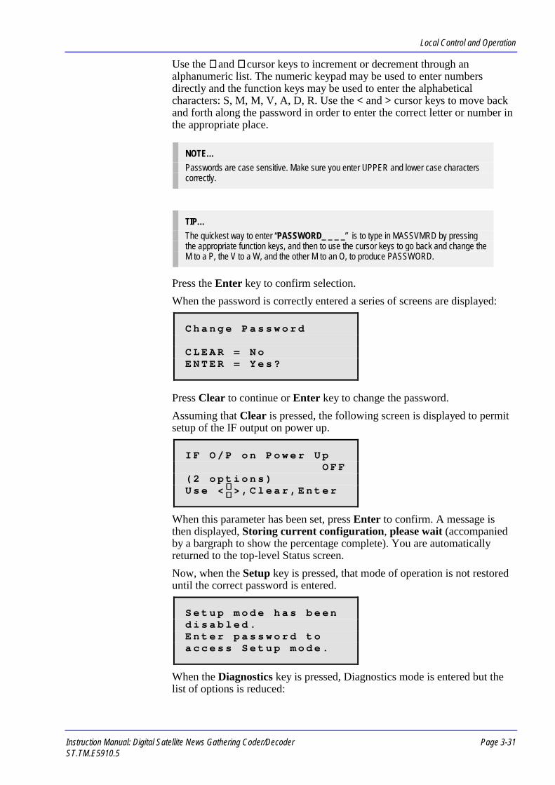
Local Control and Operation
Instruction Manual: Digital Satellite News Gathering Coder/Decoder Page 3-31ST.TM.E5910.5
Use the ∧∧∧∧ and ∨∨∨∨ cursor keys to increment or decrement through analphanumeric list. The numeric keypad may be used to enter numbersdirectly and the function keys may be used to enter the alphabeticalcharacters: S, M, M, V, A, D, R. Use the < and > cursor keys to move backand forth along the password in order to enter the correct letter or number inthe appropriate place.
NOTE…Passwords are case sensitive. Make sure you enter UPPER and lower case characterscorrectly.
TIP…The quickest way to enter “PASSWORD_ _ _ _” is to type in MASSVMRD by pressingthe appropriate function keys, and then to use the cursor keys to go back and change theM to a P, the V to a W, and the other M to an O, to produce PASSWORD.
Press the Enter key to confirm selection.When the password is correctly entered a series of screens are displayed:
C h a n g e P a s s w o r d
C L E A R = N oE N T E R = Y e s ?
Press Clear to continue or Enter key to change the password.Assuming that Clear is pressed, the following screen is displayed to permitsetup of the IF output on power up.
I F O / P o n P o w e r U pO F F
( 2 o p t i o n s )U s e < > , C l e a r , E n t e r
When this parameter has been set, press Enter to confirm. A message isthen displayed, Storing current configuration, please wait (accompaniedby a bargraph to show the percentage complete). You are automaticallyreturned to the top-level Status screen.Now, when the Setup key is pressed, that mode of operation is not restoreduntil the correct password is entered.
S e t u p m o d e h a s b e e nd i s a b l e d .E n t e r p a s s w o r d t oa c c e s s S e t u p m o d e .
When the Diagnostics key is pressed, Diagnostics mode is entered but thelist of options is reduced:
∧∧∧∧∨∨∨∨

Local Control and Operation
Page 3-32 Instruction Manual: Digital Satellite News Gathering Coder/DecoderST.TM.E5910.5
D i s p l a y E r r o r sC l o s e S c r e e n
S e l e c t O p t i o n
To restore full access to both the Setup and Diagnostics screens, simplyenter the correct password when the Setup key is pressed.
Setup / System / Chnge Disable PswdThe following setup screen permits the 12-digit password allowing access toSetup and/or Diagnostics Screens to be changed.
IMPORTANT NOTE…The equipment is supplied with password set to PASSWORD_ _ _ _. It is recommendedthat you change this immediately WHETHER YOU INTEND TO USE THIS FEATUREOR NOT. This will ensure that you are not locked out of the equipment either byaccident, or deliberately by someone else entering their own password.
C u r r e n t P a s s w o r d :_ _ _ _ _ _ _ _ _ _ _ _
U s e < > , C l e a r , E n t e r
Use the ∧∧∧∧ and ∨∨∨∨ cursor keys to increment or decrement through analphanumeric list. The numeric keypad may be used to enter numbersdirectly and the function keys may be used to enter the alphabeticalcharacters: S, M, M, V, A, D, R. Use the < and > cursor keys to move backand forth along the password in order to enter the correct letter or number inthe appropriate place.
NOTE…Passwords are case sensitive. Make sure you enter UPPER and lower case characterscorrectly.
TIP…The quickest way to enter “PASSWORD_ _ _ _” is to type in MASSVMRD by pressingthe appropriate function keys, and then to use the cursor keys to go back and change theM to a P, the V to a W, and the other M to an O, to produce PASSWORD.
Press the Enter key to confirm selection.
∧∧∧∧∨∨∨∨

Local Control and Operation
Instruction Manual: Digital Satellite News Gathering Coder/DecoderST.TM.E5910.5
3.7.8 Setup / ModulatorThe following setup screen permits changes to be made to the currentparameter settings for the DSNG Codec Modulator functions.
I F O u t p u t ( o n / o f f )I F P o w e rM o d u l a t i o n ( o n / o f f ) ↓↓↓↓
S e l e c t O p t i o n
T x B a n d w i d t hS y m b o l R a t eF E C R a t eI F F r e q u e n c yS p e c t r u m I n v e r s i o nI F P r e s e t P o w e rS a t F r e q u e n c yS a t P o s i t i o nS a t D i r e c t i o nS a t P o l a r i s a t i o nC l o s e S c r e e n
NOTE…In order to access the Setup / Modulator Multiplexer must be set to IF (as opposedFormat screen. If the IF output is not enaby a screen which allows you to make thBaseband to IF, then press Enter to conoptions.
Choose a menu option by using thalongside the required option. Theselection. A parameter setup screeheadings).Choose the Close Screen option (top level Setup screen.
Setup / Modulator / IF OutputThe following setup screen permidefault, on power-up or after a coset to off.
NOTES…1. This option may be overridden by t
option.2. IF Monitor Outputs 1 and 2 are alw
When the IF output is enabled, thesignify the equipment is “on-air”.
S5898 Version 2.3 and later.
Page 3-33
options (shown above), the output format of the to Baseband) on the Setup / Mux / Output
bled, an advisory message is displayed followedis selection. Use the cursor keys to changefirm selection and display the Setup / Modulator
e cursor keys to position the asteriskn press the Enter key to confirmn will be displayed (see the following
or press the Clear key) to go back to the
ts the main IF output to be enabled. Bynfiguration load, the IF output is normally
he Setup / System / Disable Setup/Diag
ays switched on.
Live LED on the front panel lights to

Local Control and Operation
Page 3-34 Instruction Manual: Digital Satellite News Gathering Coder/DecoderST.TM.E5910.5
I F O u t p u tO N
( O n , O f f )U s e , C l e a r , E n t e r
Use the ∧∧∧∧ and ∨∨∨∨ cursor keys to select either on or off. Press the Enter key toconfirm selection.
Setup / Modulator / IF PowerThe following setup screen permits the main IF output power level to be set.A (preset) power level may be set as a default for when a new configurationis loaded or when the equipment is switched on, see Setup / Modulator / IFPreset Power.
I F O u t p u t P o w e r- 2 7 . 0 d B m
U s e , C l e a r , E n t e r
Use the ∧∧∧∧ and ∨∨∨∨ cursor keys to increment or decrement the number in therange (+5.0 to -27.0 dBm). The numeric keypad may be used to enternumbers directly. Press the Enter key to confirm selection.
NOTE…Monitor IF outputs are fixed at -10 dBm and always turned on.
Setup / Modulator / ModulationThe following setup screen permits the IF carrier to be modulated.
M o d u l a t i o nO N
( O n , O f f )U s e , C l e a r , E n t e r
Use the ∧∧∧∧ and ∨∨∨∨ cursor keys to select either on or off. Press the Enter key toconfirm selection.
Setup / Modulator / Tx BandwidthThe following setup screen permits the IF output bandwidth to be set.
T x B a n d w i d t h1 0 . 0 0 0 M H z
( 7 . 1 8 2 M s y m / s )U s e , C l e a r , E n t e r
∧∧∧∧∨∨∨∨
∧∧∧∧∨∨∨∨
∧∧∧∧∨∨∨∨
∧∧∧∧∨∨∨∨
Symbol Rate calculatedautomatically from enteredbandwidth

Local Control and Operation
Instruction Manual: Digital Satellite News Gathering Coder/Decoder Page 3-35ST.TM.E5910.5
NOTE…If the IF output is currently set to on, the operator is prompted by a screen to SwitchOFF IF Output, before any changes can be made. When the required changes to the TxBandwidth have been entered, a screen is displayed to enable the operator to SwitchON IF Output.
Use the ∧∧∧∧ and ∨∨∨∨ cursor keys to increment or decrement the number in therange (1.92-20.48 MHz). The numeric keypad may be used to enter numbersdirectly. Press the Enter key to confirm selection.Upon entering a bandwidth value the DSNG Codec automatically calculatesthe maximum permissible symbol rate, the optimum video bit-rate(depending upon the audio and data services selected) and selects anappropriate pixel resolution (see Getting Started). These changes may take afew seconds to process and during this time advisory messages will bedisplayed.
Setup / Modulator / Symbol RateThe following setup screen permits the IF output symbol rate to be set.
S y m b o l R a t e7 . 1 8 2 M s y m / s( 1 0 . 0 0 0 M H z )
U s e C l e a r o r E n t e r
NOTE…Before changes can be made to this screen the operator is prompted with a message toallow the IF output to be turned off.
Use the ∧∧∧∧ and ∨∨∨∨ cursor keys to increment or decrement the number in therange (1.5-16 MSymbol/s). The numeric keypad may be used to enternumbers directly. Press the Enter key to confirm selection.
Setup / Modulator / FEC RateThe following setup screen permits the IF output Forward Error Correction(FEC) rate to be set.
F E C R a t e3 / 4
( 1 / 2 t o 7 / 8 )U s e , C l e a r , E n t e r
Use the ∧∧∧∧ and ∨∨∨∨ cursor keys to select the required rate from the list ofsupported options (1/2, 2/3, 3/4, 5/6, and 7/8). The numeric keypad may alsobe used (press 1, 2, 3, 5 or 7). Press the Enter key to confirm selection.
∧∧∧∧∨∨∨∨
Bandwidth value is calculatedfrom the entered symbol rateautomatically

Local Control and Operation
Page 3-36 Instruction Manual: Digital Satellite News Gathering Coder/DecoderST.TM.E5910.5
Upon entering a new FEC rate, the video bit-rate is automatically re-adjusted (and pixel resolution if necessary) to maintain the samebandwidth/symbol rate. A mid-value of 3/4 is normally used. If the signalneeds more powerful error correction, a value of 1/2 represents themaximum which may be applied, providing one error correction bit forevery one data bit.
Setup / Modulator / IF FrequencyThe following setup screen permits the IF output frequency to be set.
I F F r e q u e n c y7 0 . 0 0 0 M H z
U s e C l e a r o r E n t e r
NOTE…If the IF output is currently set to on, the operator is prompted by a screen to SwitchOFF IF Output, before any changes can be made. When the required changes to the IFFrequency have been entered, a screen is displayed to enable the operator to SwitchON IF Output.
Use the ∧∧∧∧ and ∨∨∨∨ cursor keys to increment or decrement the number in thesupported ranges (50-90 MHz and 100-180 MHz, in steps of 125 kHz). Thenumeric keypad may be used to enter numbers directly. Press the Enter keyto confirm selection.
Setup / Modulator / Spectrum InversionThe following setup screen permits the inversion of the IF spectrum.
S p e c t r u m I n v e r s i o nO F F
( O n / O f f )U s e , C l e a r , E n t e r
Use the ∧∧∧∧ and ∨∨∨∨ cursor keys to select either on or off. Press the Enter key toconfirm selection.
Setup / Modulator / IF Preset PowerThe following setup screen permits the IF preset power to be set. This valueis that to which the IF output will default whenever a configuration is loadedor when the equipment is switched on. To make operational adjustments tothis value use Setup / Modulator, IF Preset Power.
I F P r e s e t P o w e r- 2 7 . 0 d B m
U s e , C l e a r , E n t e r
∧∧∧∧∨∨∨∨
∧∧∧∧∨∨∨∨

Local Control and Operation
Instruction Manual: Digital Satellite News Gathering Coder/Decoder Page 3-37ST.TM.E5910.5
Use the ∧∧∧∧ and ∨∨∨∨ cursor keys to increment or decrement through the availablerange (+5.0 to -27.0 dBm). The numeric keypad may be used to enternumbers directly. Press the Enter key to confirm selection.
NOTE…Monitor IF Outputs are fixed at -10 dBm and are always turned on.
Setup / Modulator / Sat Frequency (S5898 Ver 2.3 and later)The following setup screen permits the Satellite Frequency to be set. Thisvalue is that to which the modulator will default whenever a configuration isloaded or when the equipment is switched on. To make operationaladjustments to this value use Setup / Modulator, Sat Frequency.
S a t e l l i t e F r e q u e n c y1 1 . 4 0 0 G H z
U s e , C l e a r , E n t e r
Use the ∧∧∧∧ and ∨∨∨∨ cursor keys to increment or decrement through the availablerange. The numeric keypad may be used to enter numbers directly. Press theEnter key to confirm selection.
Setup / Modulator / Sat Position (S5898 Ver 2.3 and later)The following setup screen permits the Satellite Position to be set. Thisvalue is that to which the modulator will default whenever a configuration isloaded or when the equipment is switched on. To make operationaladjustments to this value use Setup / Modulator, Sat Position.
S a t e l l i t e P o s i t i o n1 9 . 2 d e g s
U s e , C l e a r , E n t e r
Use the ∧∧∧∧ and ∨∨∨∨ cursor keys to increment or decrement through the availablerange. The numeric keypad may be used to enter numbers directly. Press theEnter key to confirm selection.
Setup / Modulator / Sat Direction (S5898 Ver 2.3 and later)The following setup screen permits the Satellite Direction to be set. Thisvalue is that to which the modulator will default whenever a configuration isloaded or when the equipment is switched on. To make operationaladjustments to this value use Setup / Modulator, Sat Direction.
S a t e l l i t e D i r e c t i o nE A S T
( E a s t , W e s t )U s e , C l e a r , E n t e r
Use the ∧∧∧∧ and ∨∨∨∨ cursor keys to toggle the option (East, West). Press theEnter key to confirm selection.
∧∧∧∧∨∨∨∨
∧∧∧∧∨∨∨∨
∧∧∧∧∨∨∨∨

Local Control and Operation
Page 3-38 Instruction Manual: Digital Satellite News Gathering Coder/DecoderST.TM.E5910.5
Setup / Modulator / Sat Polarisation (S5898 Ver 2.3 and later)The following setup screen permits the Satellite Polarisation to be set. Thisvalue is that to which the modulator will default whenever a configuration isloaded or when the equipment is switched on. To make operationaladjustments to this value use Setup / Modulator, Sat Polarisation.
S a t e l l i t eP o l a r i s a t i o n
L I N E A R H O R( 4 O p t i o n s )U s e , C l e a r , E n t e r
Use the ∧∧∧∧ and ∨∨∨∨ cursor keys to step through the available options (CircRight, Circ Left, Liners Vert, Liner Hor). Press the Enter key to confirmselection.
3.7.9 Setup / Mux (IF Output Selected)The following setup screen permits changes to be made to the currentparameter settings for the DSNG Codec Multiplexer functions when IF isselected as the output format.
NOTE…Additional options may be available on this screen, depending on whether IF orBaseband is selected as the output format, see also Setup / Mux (Baseband OutputSelected).
O u t p u t F o r m a tS c r a m b l e ( o n / o f f )S c r a m b l e C o d e ↓↓↓↓
S e l e c t O p t i o n
C l o s e S c r e e n
Choose a menu option by using the cursor keys to position the asteriskalongside the required option. Then press the Enter key to confirmselection. A parameter setup screen will be displayed (see the followingheadings).Choose the Close Screen option (or press the Clear key) to go back to thetop level Setup screen.
Setup / Mux / Output FormatThe following setup screen permits the format of the data output to be setfor either telecommunications link (baseband) or satellite uplink (IF)operation.
O u t p u t F o r m a tI F
( B a s e b a n d / I F )U s e , C l e a r , E n t e r∧∧∧∧
∨∨∨∨
∧∧∧∧∨∨∨∨

Local Control and Operation
Instruction Manual: Digital Satellite News Gathering Coder/Decoder Page 3-39ST.TM.E5910.5
NOTE…The choice of output format is reflected in the status summary screen.
Use the ∧∧∧∧ and ∨∨∨∨ cursor keys to select the required format from the list ofsupported options (Baseband or IF). Press the Enter key to confirmselection.
Setup / Mux / ScrambleThe following setup screen permits scrambling of the data output to beenabled. If used, a scrambling code must also be entered (see below) inorder that only the data may be accessed by the intended receiver.
S c r a m b l eO F F
( O n / O f f )U s e , C l e a r , E n t e r
Use the ∧∧∧∧ and ∨∨∨∨ cursor keys to select either on or off. Press the Enter key toconfirm selection.
Setup / Mux / Scramble CodeThe following setup screen permits a 7-digit numerical scrambling code tobe set. This code must be used at the receive end to unscramble thetransmission.
S c r a m b l e C o d e9 1 7 1 4 7 3
U s e < > , C l e a r , E n t e r
Use the ∧∧∧∧ and ∨∨∨∨ cursor keys to increment or decrement numbers. Thenumeric keypad may be used to enter numbers directly. Use the < and >cursor keys to move back and forth along the code in order to enter thecorrect number in the appropriate place. Press the Enter key to confirmselection.
3.7.10 Setup / Mux (Baseband Output Selected)The following setup screen permits changes to be made to the currentparameter settings for the DSNG Codec Multiplexer functions whenBaseband is selected as the output format.
NOTE…Fewer options may be available on this screen, depending on whether IF or Baseband isselected as the output format, see also Setup / Mux (IF Output Selected).
∧∧∧∧∨∨∨∨
∧∧∧∧∨∨∨∨

Local Control and Operation
Page 3-40 Instruction Manual: Digital Satellite News Gathering Coder/DecoderST.TM.E5910.5
O u t p u t F o r m a tM u x B i t R a t eP a c k e t L e n g t h ↓↓↓↓
S e l e c t O p t i o n
R S C o d e ( o n / o f f )B a s e b a n d O u t p u tS c r a m b l e ( o n / o f f )S c r a m b l e C o d eC l o s e S c r e e n
Choose a menu option by using the cursor keys to position the asteriskalongside the required option. Then press the Enter key to confirmselection. A parameter setup screen will be displayed (see the followingheadings).Choose the Close Screen option (or press the Clear key) to go back to thetop level Setup screen.
Setup / Mux / Output FormatThe following setup screen permits the format of the data output to be setfor either telecommunications link (baseband) or satellite uplink (IF).
O u t p u t F o r m a tB A S E B A N D
( B a s e b a n d / I F )U s e , C l e a r , E n t e r
NOTE…The choice of output format is reflected in the status summary screen which is displayed.
Use the ∧∧∧∧ and ∨∨∨∨ cursor keys to select the required format from the list ofsupported options (Baseband or IF). Press the Enter key to confirmselection.
Setup / Mux / Mux Bit RateThe following setup screen permits the Multiplexer output bit-rate to be set.
M u x B i t R a t e1 0 . 0 0 0 M b i t / s
U s e , C l e a r , E n t e r
Use the ∧∧∧∧ and ∨∨∨∨ cursor keys to increment or decrement the number in therange (2-32 Mbit/s). The numeric keypad may be used to enter numbersdirectly. Press the Enter key to confirm selection.
∧∧∧∧∨∨∨∨
∧∧∧∧∨∨∨∨
Option only displayed whenPacket Length is set to 204

Local Control and Operation
Instruction Manual: Digital Satellite News Gathering Coder/Decoder Page 3-41ST.TM.E5910.5
Setup / Mux / Packet LengthThe following setup screen permits the Multiplexer packet length to be set.This is normally set according to the requirements of the receivingequipment.
P a c k e t L e n g t h2 0 4
( 1 8 8 , 2 0 4 )U s e , C l e a r , E n t e r
Use the ∧∧∧∧ and ∨∨∨∨ cursor keys to select the required packet length from the listof options (188, 204). The numeric keypad may be used to enter numbersdirectly. Press the Enter key to confirm selection.If 204 is selected, a further option for the selection of Reed-Solomon (RS)encoding is displayed (see below). Thus, the extra 16 bits in each packet canbe filled with forward error correction (FEC) bits.
Setup / Mux / RS Code (on/off)The following setup screen permits the Multiplexer Reed-Solomon errorcorrection to be enabled. For use where there are long runs or RFI betweenthis equipment and the receiving telecommunications equipment, or leftempty (gapped) for use at the receiving end.
NOTE…This option is only displayed when 204 has been previously selected as the packetlength.
R S C o d eO N
( O n , O f f )U s e , C l e a r , E n t e r
Use the ∧∧∧∧ and ∨∨∨∨ cursor keys to select either on or off. Press the Enter key toconfirm selection.
Setup / Mux / Baseband OutputThe following setup screen permits the baseband output to be enabled. TheLive LED on the front panel is lit to signify the equipment is “on-air”.
B a s e b a n d O u t p u tO N
( O n , O f f )U s e , C l e a r , E n t e r
Use the ∧∧∧∧ and ∨∨∨∨ cursor keys to select either on or off. Press the Enter key toconfirm selection.
∧∧∧∧∨∨∨∨
∧∧∧∧∨∨∨∨
∧∧∧∧∨∨∨∨
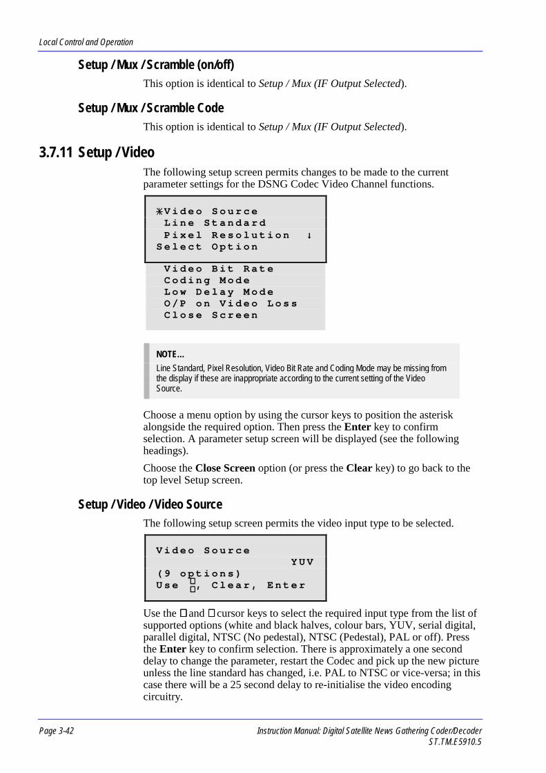
Local Control and Operation
Page 3-42 Instruction Manual: Digital Satellite News Gathering Coder/DecoderST.TM.E5910.5
Setup / Mux / Scramble (on/off)This option is identical to Setup / Mux (IF Output Selected).
Setup / Mux / Scramble CodeThis option is identical to Setup / Mux (IF Output Selected).
3.7.11 Setup / VideoThe following setup screen permits changes to be made to the currentparameter settings for the DSNG Codec Video Channel functions.
V i d e o S o u r c eL i n e S t a n d a r dP i x e l R e s o l u t i o n ↓↓↓↓
S e l e c t O p t i o n
V i d e o B i t R a t eC o d i n g M o d eL o w D e l a y M o d eO / P o n V i d e o L o s sC l o s e S c r e e n
NOTE…Line Standard, Pixel Resolution, Video Bit Rate and Coding Mode may be missing fromthe display if these are inappropriate according to the current setting of the VideoSource.
Choose a menu option by using the cursor keys to position the asteriskalongside the required option. Then press the Enter key to confirmselection. A parameter setup screen will be displayed (see the followingheadings).Choose the Close Screen option (or press the Clear key) to go back to thetop level Setup screen.
Setup / Video / Video SourceThe following setup screen permits the video input type to be selected.
V i d e o S o u r c eY U V
( 9 o p t i o n s )U s e , C l e a r , E n t e r
Use the ∧∧∧∧ and ∨∨∨∨ cursor keys to select the required input type from the list ofsupported options (white and black halves, colour bars, YUV, serial digital,parallel digital, NTSC (No pedestal), NTSC (Pedestal), PAL or off). Pressthe Enter key to confirm selection. There is approximately a one seconddelay to change the parameter, restart the Codec and pick up the new pictureunless the line standard has changed, i.e. PAL to NTSC or vice-versa; in thiscase there will be a 25 second delay to re-initialise the video encodingcircuitry.
∧∧∧∧∨∨∨∨

Local Control and Operation
Instruction Manual: Digital Satellite News Gathering Coder/Decoder Page 3-43ST.TM.E5910.5
NOTEIt is recommended that serial video should not be applied when selecting yuv input(On both 525 and 625 line Standards)
Setup / Video / Line StandardThe following setup screen permits the video input line standard to beselected.
NOTE…This option may be missing from the menu when selection of a line standard isinappropriate according to the current video source, i.e. NTSC or PAL.
L i n e S t a n d a r d6 2 5
( 5 2 5 / 6 2 5 )U s e , C l e a r , E n t e r
Use the ∧∧∧∧ and ∨∨∨∨ cursor keys to select the required line standard from the listof supported options (525 or 625). The numeric keypad may also be used(press 5 or 6). Press the Enter key to confirm selection. There isapproximately a 25 second delay to re-initialise the video encoding circuitry.
Setup / Video / Pixel ResolutionThe following setup screen permits the video input pixel resolution to beselected. Normally, resolution is selected automatically to optimise systemcapacity. However, this value can be overridden and entered manually, if sodesired.
P i x e l R e s o l u t i o nA U T O ( 3 / 4 )
( 6 o p t i o n s )U s e , C l e a r , E n t e r
Use the ∧∧∧∧ and ∨∨∨∨ cursor keys to select the required resolution from the list ofsupported options (Full Res., 3/4 Res., 2/3 Res., 1/2 Res., SIF, Auto).
NOTE…SIF mode bit rates are limited to 1.5 - 5 Mbit/s.
Press the Enter key to confirm selection.
∧∧∧∧∨∨∨∨
∧∧∧∧∨∨∨∨
Brackets indicate that value was selectedautomatically by the software

Local Control and Operation
Page 3-44 Instruction Manual: Digital Satellite News Gathering Coder/DecoderST.TM.E5910.5
Setup / Video / Video Bit RateThe following setup screen permits the video bit-rate to be selected.Normally, bit-rate is selected automatically to optimise system capacity.However, this value can be overridden and entered manually, if so desired.
V i d e o B i t R a t e1 3 . 6 3 0 M b i t / s
U s e , C l e a r , E n t e r
Use the ∧∧∧∧ and ∨∨∨∨ cursor keys to increment or decrement through the availablerange (1.5 to 5 Mbit/s for SIF mode, 2 to 15 Mbit/s all other).The numerickeypad may be used to enter numbers directly. Press the Enter key toconfirm selection.Upon entering the desired bit-rate, the pixel resolution may be re-adjustedautomatically. If bit-rate is entered manually, it will not be alteredautomatically by software unless the output configuration has been changedin such a way that the selected bit-rate is no longer valid, i.e. achievable. Inthis event, an advisory message is displayed. Entering an invalid video bit-rate value for the current configuration will have the same effect. When theVideo Source is set to Off, the bit-rate may be configured for when it isnext turned On.
Setup / Video / Coding ModeThe following setup screen permits the video coding mode to be selected.The different modes allow more or less (or none) bi-directionally predictive(B) frames to be used in the compressed video data stream. IBBP is thedefault mode.
C o d i n g M o d eI B B P
( I P , I B P , I B B P )U s e , C l e a r , E n t e r
Use the ∧∧∧∧ and ∨∨∨∨ cursor keys to select the required mode from the list ofsupported options (IP, IBP, IBBP). Press the Enter key to confirm selection.
NOTE…This option is not available if Low Delay Mode is selected.
Setup / Video / Low Delay ModeThe following setup screen permits the video low delay mode to be enabled.This option minimises the delay in encoding the video signal by trading-offvideo quality. When the low delay mode is enabled, the pixel resolution isset to 1/2 (352) and can not be altered. If a higher resolution is required, themanual resolution option should be selected; higher resolutions are thensupported at the expense of a larger coding delay.
∧∧∧∧∨∨∨∨
∧∧∧∧∨∨∨∨
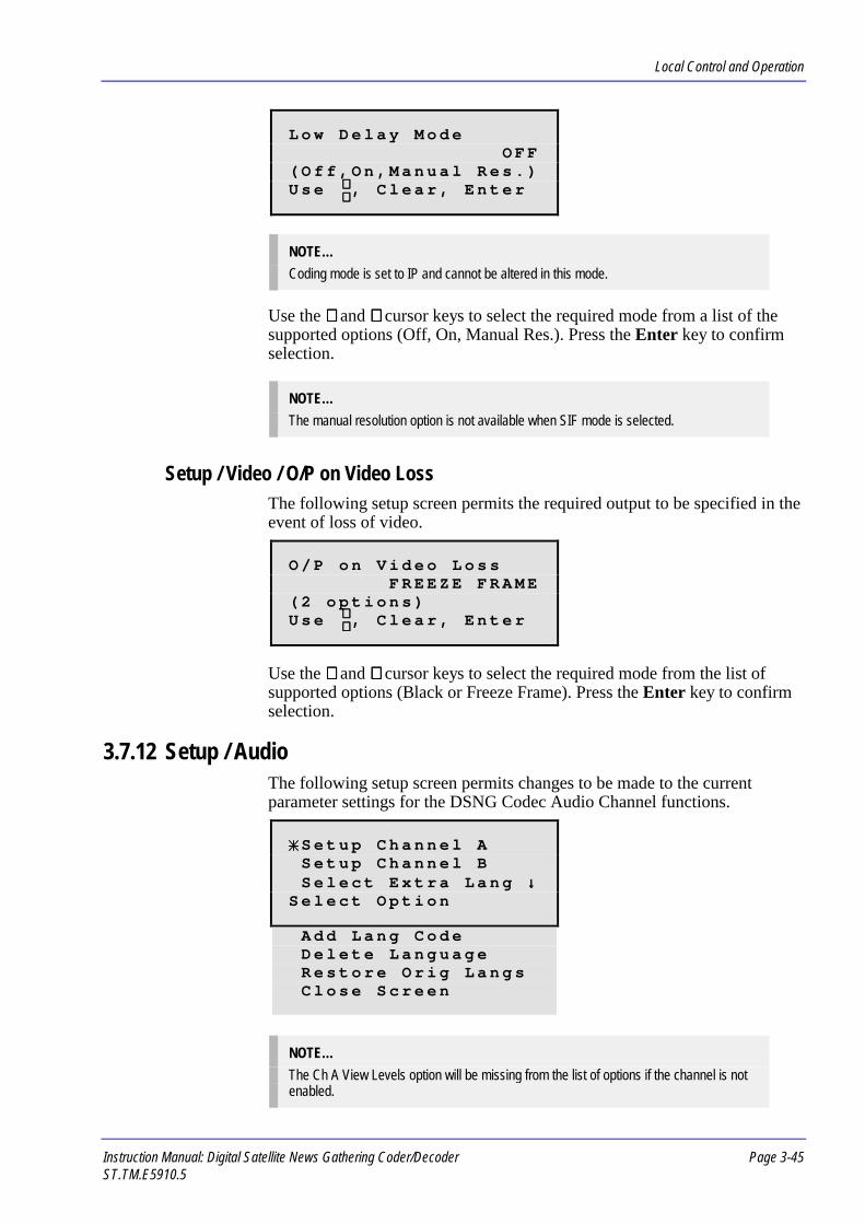
Local Control and Operation
Instruction Manual: Digital Satellite News Gathering Coder/Decoder Page 3-45ST.TM.E5910.5
L o w D e l a y M o d eO F F
( O f f , O n , M a n u a l R e s . )U s e , C l e a r , E n t e r
NOTE…Coding mode is set to IP and cannot be altered in this mode.
Use the ∧∧∧∧ and ∨∨∨∨ cursor keys to select the required mode from a list of thesupported options (Off, On, Manual Res.). Press the Enter key to confirmselection.
NOTE…The manual resolution option is not available when SIF mode is selected.
Setup / Video / O/P on Video LossThe following setup screen permits the required output to be specified in theevent of loss of video.
O / P o n V i d e o L o s sF R E E Z E F R A M E
( 2 o p t i o n s )U s e , C l e a r , E n t e r
Use the ∧∧∧∧ and ∨∨∨∨ cursor keys to select the required mode from the list ofsupported options (Black or Freeze Frame). Press the Enter key to confirmselection.
3.7.12 Setup / AudioThe following setup screen permits changes to be made to the currentparameter settings for the DSNG Codec Audio Channel functions.
S e t u p C h a n n e l AS e t u p C h a n n e l BS e l e c t E x t r a L a n g ↓↓↓↓
S e l e c t O p t i o n
A d d L a n g C o d eD e l e t e L a n g u a g eR e s t o r e O r i g L a n g sC l o s e S c r e e n
NOTE…The Ch A View Levels option will be missing from the list of options if the channel is notenabled.
∧∧∧∧∨∨∨∨
∧∧∧∧∨∨∨∨

Local Control and Operation
Page 3-46 Instruction Manual: Digital Satellite News Gathering Coder/DecoderST.TM.E5910.5
Choose a menu option by using the cursor keys to position the asteriskalongside the required option. Then press the Enter key to confirmselection. Depending on the option selected, either a parameter setup screenor a further list of options will be displayed (see the following headings).Choose the Close Screen option (or press the Clear key) to go back to thetop level Setup screen.
Setup / Audio / Setup Channel AThe following setup screen permits changes to be made to the currentparameter settings for the Channel A audio functions.
C h A ( o n / m u t e / t o n e )C h A C o d i n g M o d eC h A T y p e ↓↓↓↓
S e l e c t O p t i o n
C h A B i t R a t eC h A L a n g u a g eC h A V i e w L e v e l sC l o s e S c r e e n
Choose a menu option by using the cursor keys to position the asteriskalongside the required option. Then press the Enter key to confirmselection. A parameter setup screen will be displayed (see the followingheadings).Choose the Close Screen option (or press the Clear key) to go back to theSetup / Audio screen.
Setup / Audio / Setup Channel A / Ch A (on/mute/tone)The following setup screen permits Channel A to be enabled, or a tone to beinserted for testing/alignment purposes.
C h a n n e l A :O N
( O n , M u t e , T e s t T o n e )U s e , C l e a r , E n t e r
Use the ∧∧∧∧ and ∨∨∨∨ cursor keys to select the required mode from the list ofsupported options (on, mute, test tone). Press the Enter key to confirmselection.Setup / Audio / Setup Channel A / Ch A Coding ModeThe following setup screen permits Channel A coding mode to be selected.
C h A C o d i n g M o d eS T E R E O
( M o n o t o S t e r e o )U s e , C l e a r , E n t e r
∧∧∧∧∨∨∨∨
∧∧∧∧∨∨∨∨

Local Control and Operation
Instruction Manual: Digital Satellite News Gathering Coder/Decoder Page 3-47ST.TM.E5910.5
Use the ∧∧∧∧ and ∨∨∨∨ cursor keys to select the required mode from the list ofsupported options (stereo, joint stereo, dual mono, mono). Press the Enterkey to confirm selection.Setup / Audio / Setup Channel A / Ch A TypeThe following setup screen permits Channel A input type to be selected.
C h a n n e l A T y p e6 0 0 O h m s ( A n a l o g u e )
( 3 o p t i o n s )U s e , C l e a r , E n t e r
Use the ∧∧∧∧ and ∨∨∨∨ cursor keys to select the required mode from the list ofsupported options (600 Ohms (Analogue), 20 kOhms (Analogue), digital).Press the Enter key to confirm selection.
Setup / Audio / Setup Channel A / Ch A Bit RateThe following setup screen permits Channel A input bit rate to be selected.
C h a n n e l A B i t R a t e3 8 4 k b i t / s
( 1 0 o p t i o n s )U s e , C l e a r , E n t e r
Use the ∧∧∧∧ and ∨∨∨∨ cursor keys to select the required bit rate from the list ofsupported options (dependent on selected mode). Press the Enter key toconfirm selection.
NOTE…When Mute or Test Tone is selected, the actual bit rate is fixed at 64 kbit/s. Anyadjustment made to the bit rate will be applied to the audio channel when it is next turnedon.
Setup / Audio / Setup Channel A / Ch A LanguageThe following setup screen permits language identifier to be set as ServiceInformation to the audio channel. Language may be set separately for left (L)and right (R) channels depending on the mode selected.
C h A L a n g u a g eE N G L I S H
( 1 2 o p t i o n s ) ( e n g )U s e , C l e a r , E n t e r
Use the ∧∧∧∧ and ∨∨∨∨ cursor keys to select the required language from a short-form list of default options (English, French, German, Dutch, Spanish,Portuguese, Italian, Danish, Norwegian, Swedish, Finnish or undefined).Press the Enter key to confirm selection. For more language options seeSetup / Audio / Select Extra Lang. If the language you are looking for is notpresent, enter it by using the Add Lang Code option.
∧∧∧∧∨∨∨∨
∧∧∧∧∨∨∨∨
∧∧∧∧∨∨∨∨

Local Control and Operation
Page 3-48 Instruction Manual: Digital Satellite News Gathering Coder/DecoderST.TM.E5910.5
Setup / Audio / Setup Channel A / Ch A View LevelsThe following setup screen permits Channel A input levels to be displayed.
C h a n n e l A :L :R :A n y K e y t o C o n t i n u e
NOTE…This option may be missing from the menu when channels are not enabled.
The screen provides a bargraph-type display of the audio activity on the left(L) and right (R) channels. The bargraph is graded in eight levels, zerocorresponding to silence and level eight corresponding to clipping. Press anykey to return to the Setup / Audio / Setup Channel A screen.
Setup / Audio / Setup Channel BThese screens are the same as for Channel A described above.
Setup / Audio / Select Extra LangThe following setup screen permits additional languages to be added to thedefault 12 option short-form list available to Channels A and B.
S e l e c t L a n g u a g eA F R I K A A N S
( A f r i k a a n s t o W e l s h )U s e < > , C l e a r , E n t e r
Use the ∧∧∧∧ and ∨∨∨∨ cursor keys to select the required language from the full list(Afrikaans to Welsh). Press the Enter key to confirm selection.
Setup / Audio / Add Lang CodeThe following setup screen permits a user defined language identifier to beadded to the default list on Channel A.
E n t e r 3 l e t t e r c o d ea a a
U s e < > , C l e a r , E n t e r
Use the ∧∧∧∧ and ∨∨∨∨ cursor keys to increment or decrement through analphanumeric list. Use the < and > cursor keys to move back and forth alongthe code in order to enter the correct letter in the appropriate place. Press theEnter key to confirm selection.When entered, two further screens are displayed to make the descriptionentry and confirm that the code is included in the list of languages.
∧∧∧∧∨∨∨∨
∧∧∧∧∨∨∨∨

Local Control and Operation
Instruction Manual: Digital Satellite News Gathering Coder/Decoder Page 3-49ST.TM.E5910.5
Setup / Audio / Delete LanguageThe following setup screen permits languages to be deleted from thelanguage list.
D e l e t e L a n g u a g e :G E R M A N
( 1 2 o p t i o n s )U s e , C l e a r , E n t e r
Use the ∧∧∧∧ and ∨∨∨∨ cursor keys to select the required language from the list ofsupported options. Press the Enter key to confirm deletion.
Setup / Audio / Restore Orig LangsThe following option restores the default 12 languages.
S t o r i n g D a t a
The above screen is displayed for a few seconds before returningautomatically to the setup / audio screen.
3.7.13 Setup / DataThe following setup screen permits changes to be made to the currentparameter settings for the DSNG Codec Data Channel functions.
R S 2 3 2 C h a n n e l AR S 2 3 2 C h a n n e l BR S 4 2 2 C h a n n e l ↓↓↓↓
S e l e c t O p t i o n
C l o s e S c r e e n
Choose a menu option by using the cursor keys to position the asteriskalongside the required option. Then press the Enter key to confirmselection. Depending on the option selected, either a parameter setup screenor a further list of options will be displayed (see the following headings).Choose the Close Screen option (or press the Clear key) to go back to thetop level Setup screen.
∧∧∧∧∨∨∨∨

Local Control and Operation
Page 3-50 Instruction Manual: Digital Satellite News Gathering Coder/DecoderST.TM.E5910.5
Setup / Data / RS232 Channel AThe following setup screen permits changes to be made to the currentparameter settings for the DSNG Codec RS232 asynchronous DataChannel A.
R S 2 3 2 C h A ( o n / o f f )C h A B a u d R a t eC l o s e S c r e e n
S e l e c t O p t i o n
Choose a menu option by using the cursor keys to position the asteriskalongside the required option. Then press the Enter key to confirmselection. A parameter setup screen will be displayed (see the followingheadings).Choose the Close Screen option (or press the Clear key) to go back to theSetup / Data screen.
Setup / Data / RS232 Channel A/ RS232 Ch A (on/off)The following setup screen permits RS232 Data Channel A to be enabled.
R S 2 3 2 C h a n n e l AO F F
( O n , O f f )U s e , C l e a r , E n t e r
Use the ∧∧∧∧ and ∨∨∨∨ cursor keys to select either on or off. Press the Enter key toconfirm selection.
Setup / Data / RS232 Channel A/ ChA Baud RateThe following setup screen permits RS232 Data Channel A baud rate to beset.
R S 2 3 2 C h a n n e l A9 6 0 0 b a u d
( 4 o p t i o n s )U s e , C l e a r , E n t e r
Use the ∧∧∧∧ and ∨∨∨∨ cursor keys to select the required baud rate from the list ofsupported options (9600, 4800, 2400, or 1200). Press the Enter key toconfirm selection.
NOTE…When the data channel is turned off, any adjustment made to the baud rate will beactioned when it is next turned on.
∧∧∧∧∨∨∨∨
∧∧∧∧∨∨∨∨

Local Control and Operation
Instruction Manual: Digital Satellite News Gathering Coder/Decoder Page 3-51ST.TM.E5910.5
Setup / Data / RS232 Channel BThese screens are the same as for RS232 Channel A, described above.
Setup / Data / RS422 ChannelThe following setup screen permits changes to be made to the currentparameter settings for the DSNG Codec RS422 synchronous Data Channel.
R S 4 2 2 ( o n / o f f )R S 4 2 2 B i t R a t eC l o s e S c r e e n
S e l e c t O p t i o n
Choose a menu option by using the cursor keys to position the asteriskalongside the required option. Then press the Enter key to confirmselection. A parameter setup screen will be displayed (see the followingheadings).Choose the Close Screen option (or press the Clear key) to go back to theSetup / Data screen.
Setup / Data / RS422 Channel / RS422 (on/off)The following setup screen permits RS422 Data Channel to be enabled.
R S 4 2 2 C h a n n e lO F F
( O n , O f f )U s e , C l e a r , E n t e r
Use the ∧∧∧∧ and ∨∨∨∨ cursor keys to select either on or off. Press the Enter key toconfirm selection.
Setup / Data / RS422 Data Channel / RS422 Bit RateThe following setup screen permits RS422 Data Channel bit-rate to be set.
R S 4 2 2 B i t R a t e4 4 8 k b i t s / s
( 1 6 o p t i o n s )U s e , C l e a r , E n t e r
Use the ∧∧∧∧ and ∨∨∨∨ cursor keys to select the required bit-rate from the list ofsupported options (1024, 960, 896, 832, 768, 704, 640, 576, 512, 448, 384,320, 256, 192, 128, 64). Press the Enter key to confirm selection.
NOTE…When the data channel is turned off, any adjustment made to the bit rate will be actionedwhen it is next turned on.
∧∧∧∧∨∨∨∨
∧∧∧∧∨∨∨∨

Local Control and Operation
Page 3-52 Instruction Manual: Digital Satellite News Gathering Coder/DecoderST.TM.E5910.5
3.7.14 Setup / ReceiverThe following screen permits changes to be made to the Receiverparameters.
R e c e i v e r M o d eI n p u t I n t e r f a c eS e t u p T u n e r
S e l e c t O p t i o n
S e t u p D e m o d u l a t o rS e t u p S e r v i c eV i d e o P a r a m e t e r sA u d i o P a r a m e t e r sS c r a m b l e C o d eC l o s e S c r e e n
Setup / Receiver / Receiver ModeThe following setup screen permits selection of the Receiver input mode.The IRD may be set up to track the transmission generated by the DSNG(internally at baseband, or externally at IF or L-band) or to receive anddecode a totally independent transmission from some other source (atbaseband or L-band).
R e c e i v e r M o d eT R A C K I N G
( 2 o p t i o n s )U s e , C l e a r , E n t e r
Use the ∧∧∧∧ and ∨∨∨∨ cursor keys to select the required input mode from the listof supported options (independent, tracking). Press the Enter key to confirmselection.
Setup / Receiver / Input InterfaceThe following setup screen permits selection of the type of input to bereceived.
I n p u t I n t e r f a c eI N T E R N A L
( 3 o p t i o n s )U s e , C l e a r , E n t e r
Use the ∧∧∧∧ and ∨∨∨∨ cursor keys to select the required input type from the list ofsupported options (L-band, IF, internal). If an independent broadcast isselected (see above) then only two options are displayed: L-band andbaseband. Press the Enter key to confirm selection.
∧∧∧∧∨∨∨∨
∧∧∧∧∨∨∨∨
IF and L-band only(see Input Interface)
independent only(see Receiver Mode)
Only 2 options (L-band andbaseband) if independent isselected

Local Control and Operation
Instruction Manual: Digital Satellite News Gathering Coder/Decoder Page 3-53ST.TM.E5910.5
Setup / Receiver / Setup TunerThe following setup screen permits set up of the Receiver Tuner, when theinput interface (above) has been set to receive either IF or L-band inputs.
C a r r i e r F r e q u e n c yL N B L O F r e q u e n c yL N B P o w e r O n / O f f
S e l e c t O p t i o n
P o l a r i s a t i o nS p e c t r u m I n v e r s i o n
C l o s e S c r e e n
Setup / Receiver / Setup Tuner / Carrier FrequencyThe following setup screen permits the tuner carrier frequency to be set,when receiving an L-band signal.
C a r r i e r F r e q u e n c y1 1 . 0 7 0 0 0 0 G H z
U s e , C l e a r , E n t e r
Use the ∧∧∧∧ and ∨∨∨∨ cursor keys to increment or decrement through the availablerange (1 to 20 GHz). The numeric keypad may be used to enter numbersdirectly. Press the Enter key to confirm selection.
Setup / Receiver / Setup Tuner / LNB LO FrequencyThe following setup screen permits the tuner Low Noise Block localoscillator frequency to be set, when receiving an L-band signal.
L N B L O F r e q u e n c y1 0 . 0 0 0 0 0 0 G H z
U s e , C l e a r , E n t e r
Use the ∧∧∧∧ and ∨∨∨∨ cursor keys to increment or decrement through the availablerange (0 to 20 GHz). The numeric keypad may be used to enter numbersdirectly. Press the Enter key to confirm selection.
Setup / Receiver / Setup Tuner / LNB Power On/OffThe following setup screen permits the tuner Low Noise Block power dcpower supply output to be enabled at the L-band connector.
L N B P o w e rO F F
( O n , O f f )U s e , C l e a r , E n t e r
∧∧∧∧∨∨∨∨
∧∧∧∧∨∨∨∨
∧∧∧∧∨∨∨∨
L-band only
L-band andindependent
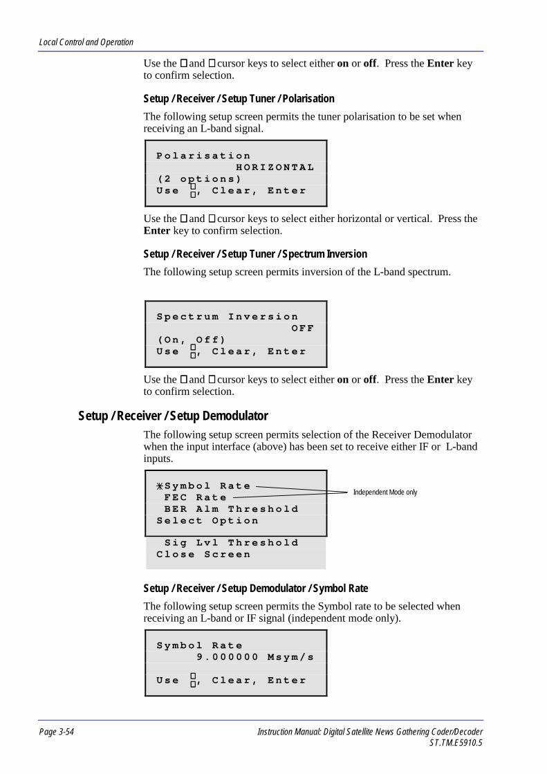
Local Control and Operation
Page 3-54 Instruction Manual: Digital Satellite News Gathering Coder/DecoderST.TM.E5910.5
Use the ∧∧∧∧ and ∨∨∨∨ cursor keys to select either on or off. Press the Enter keyto confirm selection.
Setup / Receiver / Setup Tuner / PolarisationThe following setup screen permits the tuner polarisation to be set whenreceiving an L-band signal.
P o l a r i s a t i o nH O R I Z O N T A L
( 2 o p t i o n s )U s e , C l e a r , E n t e r
Use the ∧∧∧∧ and ∨∨∨∨ cursor keys to select either horizontal or vertical. Press theEnter key to confirm selection.
Setup / Receiver / Setup Tuner / Spectrum InversionThe following setup screen permits inversion of the L-band spectrum.
S p e c t r u m I n v e r s i o nO F F
( O n , O f f )U s e , C l e a r , E n t e r
Use the ∧∧∧∧ and ∨∨∨∨ cursor keys to select either on or off. Press the Enter keyto confirm selection.
Setup / Receiver / Setup DemodulatorThe following setup screen permits selection of the Receiver Demodulatorwhen the input interface (above) has been set to receive either IF or L-bandinputs.
S y m b o l R a t eF E C R a t eB E R A l m T h r e s h o l d
S e l e c t O p t i o n
S i g L v l T h r e s h o l dC l o s e S c r e e n
Setup / Receiver / Setup Demodulator / Symbol RateThe following setup screen permits the Symbol rate to be selected whenreceiving an L-band or IF signal (independent mode only).
S y m b o l R a t e9 . 0 0 0 0 0 0 M s y m / s
U s e , C l e a r , E n t e r
∧∧∧∧∨∨∨∨
∧∧∧∧∨∨∨∨
∧∧∧∧∨∨∨∨
Independent Mode only

Local Control and Operation
Instruction Manual: Digital Satellite News Gathering Coder/Decoder Page 3-55ST.TM.E5910.5
Use the ∧∧∧∧ and ∨∨∨∨ cursor keys to increment or decrement through the availablerange (1.5 to 30 Msym/s). The numeric keypad may be used to enternumbers directly. Press the Enter key to confirm selection.
Setup / Receiver / Setup Demodulator / FEC RateThe following setup screen permits the Forward Error Correction rate to beselected when receiving an L-band or IF signal (independent mode only).
F E C R a t e3 / 4
( 1 / 2 t o 7 / 8 )U s e , C l e a r , E n t e r
Use the ∧∧∧∧ and ∨∨∨∨ cursor keys to increment or decrement through the availablerange (1/2, 2/3, 3/4 , 5/6, 7/8). The numeric keypad may be used to enternumbers directly. Press the Enter key to confirm selection.
Setup / Receiver / Setup Demodulator / BER Alarm ThresholdThe following setup screen permits the Bit Error Rate alarm threshold to beset when receiving an L-band or IF signal.
B E R A l r m T h r e s h o l d1 e - 5
( 1 e - 5 t o 9 e - 2 )U s e , C l e a r , E n t e r
Use the ∧∧∧∧ and ∨∨∨∨ cursor keys to increment or decrement through the availablerange (1 e -5 to 9 e -2). The numeric keypad may be used to enter numbersdirectly. Press the Enter key to confirm selection.
Setup / Receiver / Setup Demodulator / Signl Lvl ThresholThe following setup screen permits the signal level threshold to be set whenreceiving an L-band or IF signal.
S i g n l L v l T h r e s h o l d1 3 0
U s e , C l e a r , E n t e r
Use the ∧∧∧∧ and ∨∨∨∨ cursor keys to increment or decrement through the availablerange (0 to 255). The numeric keypad may be used to enter numbersdirectly. Press the Enter key to confirm selection.
∧∧∧∧∨∨∨∨
∧∧∧∧∨∨∨∨
∧∧∧∧∨∨∨∨
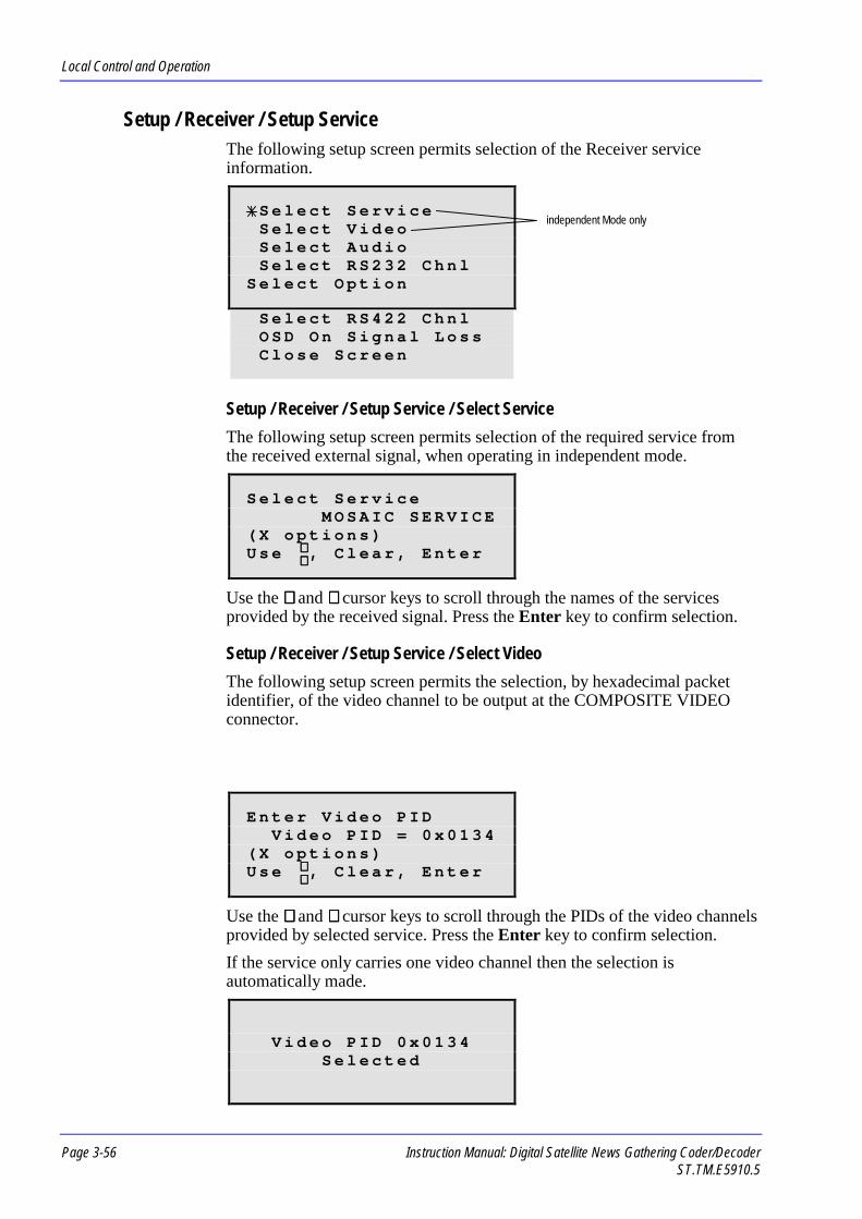
Local Control and Operation
Page 3-56 Instruction Manual: Digital Satellite News Gathering Coder/DecoderST.TM.E5910.5
Setup / Receiver / Setup ServiceThe following setup screen permits selection of the Receiver serviceinformation.
S e l e c t S e r v i c eS e l e c t V i d e oS e l e c t A u d i oS e l e c t R S 2 3 2 C h n l
S e l e c t O p t i o n
S e l e c t R S 4 2 2 C h n lO S D O n S i g n a l L o s sC l o s e S c r e e n
Setup / Receiver / Setup Service / Select ServiceThe following setup screen permits selection of the required service fromthe received external signal, when operating in independent mode.
S e l e c t S e r v i c eM O S A I C S E R V I C E
( X o p t i o n s )U s e , C l e a r , E n t e r
Use the ∧∧∧∧ and ∨∨∨∨ cursor keys to scroll through the names of the servicesprovided by the received signal. Press the Enter key to confirm selection.
Setup / Receiver / Setup Service / Select VideoThe following setup screen permits the selection, by hexadecimal packetidentifier, of the video channel to be output at the COMPOSITE VIDEOconnector.
E n t e r V i d e o P I DV i d e o P I D = 0 x 0 1 3 4
( X o p t i o n s )U s e , C l e a r , E n t e r
Use the ∧∧∧∧ and ∨∨∨∨ cursor keys to scroll through the PIDs of the video channelsprovided by selected service. Press the Enter key to confirm selection.If the service only carries one video channel then the selection isautomatically made.
V i d e o P I D 0 x 0 1 3 4S e l e c t e d
∧∧∧∧∨∨∨∨
∧∧∧∧∨∨∨∨
independent Mode only

Local Control and Operation
Instruction Manual: Digital Satellite News Gathering Coder/Decoder Page 3-57ST.TM.E5910.5
Setup / Receiver / Setup Service / Select AudioThe following setup screen permits the selection, by hexadecimal packetidentifier, of the audio channel to be output at the L and R connectors (seeSetup / Receiver / Audio Parameters / Set Audio Routing for details of thesupported options)
S e l e c t A u d i oE N G L I S H
( X o p t i o n s ) 0 x 0 1 0 0U s e , C l e a r , E n t e r
Use the ∧∧∧∧ and ∨∨∨∨ cursor keys to scroll through the PIDs of the audio channelsprovided by selected service. Press the Enter key to confirm selection.If the service only carries one audio channel then the selection isautomatically made.
A u d i o P I D 0 x 0 1 0 0S e l e c t e d
Use the ∧∧∧∧ and ∨∨∨∨ cursor keys to display the PID from the two audio channels(L and R). Press the Enter key to confirm selection.Setup / Receiver / Setup Service / Select RS232 ChnlThe following setup screen permits the selection, by hexadecimal packetidentifier, of the asynchronous data channel to be output at the RS-232connector.
E n t e r R S 2 3 2 P I DR S 2 3 2 P I D = 0 x 0 1 0 2
( X o p t i o n s )U s e , C l e a r , E n t e r
Use the ∧∧∧∧ and ∨∨∨∨ cursor keys to scroll through the PIDs of the asynchronousdata channels provided by selected service. Press the Enter key to confirmselection.If the service only carries one asynchronous data channel then the selectionis automatically made.
R S 2 3 2 P I D 0 x 0 1 0 2S e l e c t e d
Setup / Receiver / Setup Service / Select RS422 ChnlThe following setup screen permits the selection, by hexadecimal packetidentifier, of the asynchronous data channel to be output at the RS-422connector.
∧∧∧∧∨∨∨∨
∧∧∧∧∨∨∨∨

Local Control and Operation
Page 3-58 Instruction Manual: Digital Satellite News Gathering Coder/DecoderST.TM.E5910.5
E n t e r R S 4 2 2 P I DR S 4 2 2 P I D = 0 x 0 1 0 4
( X o p t i o n s )U s e , C l e a r , E n t e r
Use the ∧∧∧∧ and ∨∨∨∨ cursor keys to scroll through the PIDs of the synchronousdata channels provided by selected service. Press the Enter key to confirmselection.If the service only carries one synchronous data channel then the selection isautomatically made.
R S 4 2 2 P I D 0 x 0 1 0 4S e l e c t e d
Setup / Receiver / Setup Service / OSD on Signal LossThe following setup screen permits selection of the choice of output to besent to the Receiver Monitor on-screen display (OSD) on signal loss.
O S D O n S i g n a l L o s sO N
( O n , O f f )U s e , C l e a r , E n t e r
Use the ∧∧∧∧ and ∨∨∨∨ cursor keys to select either on or off. Press the Enter key toconfirm selection.
Setup / Receiver / Video ParametersThe following setup screen permits selection of the Receiver videoparameters.
6 2 5 L i n e S t a n d a r d5 2 5 L i n e S t a n d a r dO / P o n V i d e o L o s s
S e l e c t O p t i o n
S y n c s o n V i d e o L o s sC l o s e S c r e e n
∧∧∧∧∨∨∨∨
∧∧∧∧∨∨∨∨

Local Control and Operation
Instruction Manual: Digital Satellite News Gathering Coder/Decoder Page 3-59ST.TM.E5910.5
Setup / Receiver / Video Parameters / 625 Line StandardThe following setup screen permits selection of the Receiver video linestandard.
6 2 5 L i n e S t a n d a r dP A L
( A l a r m , P A L )U s e , C l e a r , E n t e r
Use the ∧∧∧∧ and ∨∨∨∨ cursor keys to select the required line standard from the listof supported options (Alarm, PAL). Press the Enter key to confirmselection.
Setup / Receiver / Video Parameters / 525 Line StandardThe following setup screen permits selection of the Receiver video linestandard.
5 2 5 L i n e S t a n d a r dN T S C ( P E D E S T A L )
( 4 o p t i o n s )U s e , C l e a r , E n t e r
Use the ∧∧∧∧ and ∨∨∨∨ cursor keys to select the required line standard from the listof supported options (NSTC (no pedestal), NTSC (pedestal), PAL (525),Alarm). Press the Enter key to confirm selection.
Setup / Receiver / Video Parameters / O/P on Video LossThe following setup screen permits selection of the choice of output to betransmitted from the main video output on signal loss.
O / P o n V i d e o L o s sF R E E Z E F R A M E
( 2 o p t i o n s )U s e , C l e a r , E n t e r
Use the ∧∧∧∧ and ∨∨∨∨ cursor keys to select the required output from the list ofsupported options (freeze frame, black output). Press the Enter key toconfirm selection.
Setup / Receiver / Video Parameters / Syncs on Video LossThe following setup screen permits selection of the picture synchronisationwhen the incoming video signal has been lost. The selected output (freeze,frame or black, see above) can be maintained indefinitely (by selecting 0seconds) or maintained for up to 300 seconds.
S y n c s o n V i d e o L o s s0 s e c o n d s
U s e , C l e a r , E n t e r
∧∧∧∧∨∨∨∨
∧∧∧∧∨∨∨∨
∧∧∧∧∨∨∨∨
∧∧∧∧∨∨∨∨

Local Control and Operation
Page 3-60 Instruction Manual: Digital Satellite News Gathering Coder/DecoderST.TM.E5910.5
Use the ∧∧∧∧ and ∨∨∨∨ cursor keys to increment or decrement the number in therange (0 - 300 seconds). The numeric keypad may be used to enter numbersdirectly. Press the Enter key to confirm selection.
Setup / Receiver / Audio ParametersThe following setup screen permits selection of the Receiver audioparameters.
S e t A u d i o R o u t i n gS e t A u d i o G a i nC l o s e S c r e e n
S e l e c t O p t i o n
Setup / Receiver / Audio Parameters / Set Audio RoutingThe following setup screen permits the routing of audio channel signals tothe rear panel left and right audio connectors. This should be set accordingto the coding mode used by the audio channel.
S e t A u d i o R o u t i n gS T E R E O L > L , R > R
( 4 o p t i o n s )U s e , C l e a r , E n t e r
Use the ∧∧∧∧ and ∨∨∨∨ cursor keys to select the required audio mode from the listof supported options (mono R > L & R, mono L > L & R, mono(L+R)/2 > L & R, stereo L>L R>R). Press the Enter key to confirmselection.
Setup / Receiver / Audio Parameters / Set Audio GainThe following setup screen permits selection of the Receiver audio gain.
S e t A u d i o G a i n+ 1 2 d B m
( + 9 d B m t o + 1 8 d B m )U s e , C l e a r , E n t e r
Use the ∧∧∧∧ and ∨∨∨∨ cursor keys to select the required audio gain from the list ofsupported options (+9, +12, +15, +18 dBm). Press the Enter key to confirmselection.
Setup / Receiver / Scramble CodeThe following setup screen permits selection of the 7-digit numericalscramble code (in independent mode only) which must be entered to matchthat of the transmitted signal.
S c r a m b l e C o d e9 1 7 1 4 7 3
U s e , C l e a r , E n t e r
∧∧∧∧∨∨∨∨
∧∧∧∧∨∨∨∨
∧∧∧∧∨∨∨∨

Local Control and Operation
Instruction Manual: Digital Satellite News Gathering Coder/Decoder Page 3-61ST.TM.E5910.5
Use the ∧∧∧∧ and ∨∨∨∨ cursor keys to increment or decrement numbers. Thenumeric keypad may be used to enter numbers directly. Use the < and >cursor keys to move back and forth along the code in order to enter thecorrect number in the appropriate place. Press the Enter key to confirmselection.
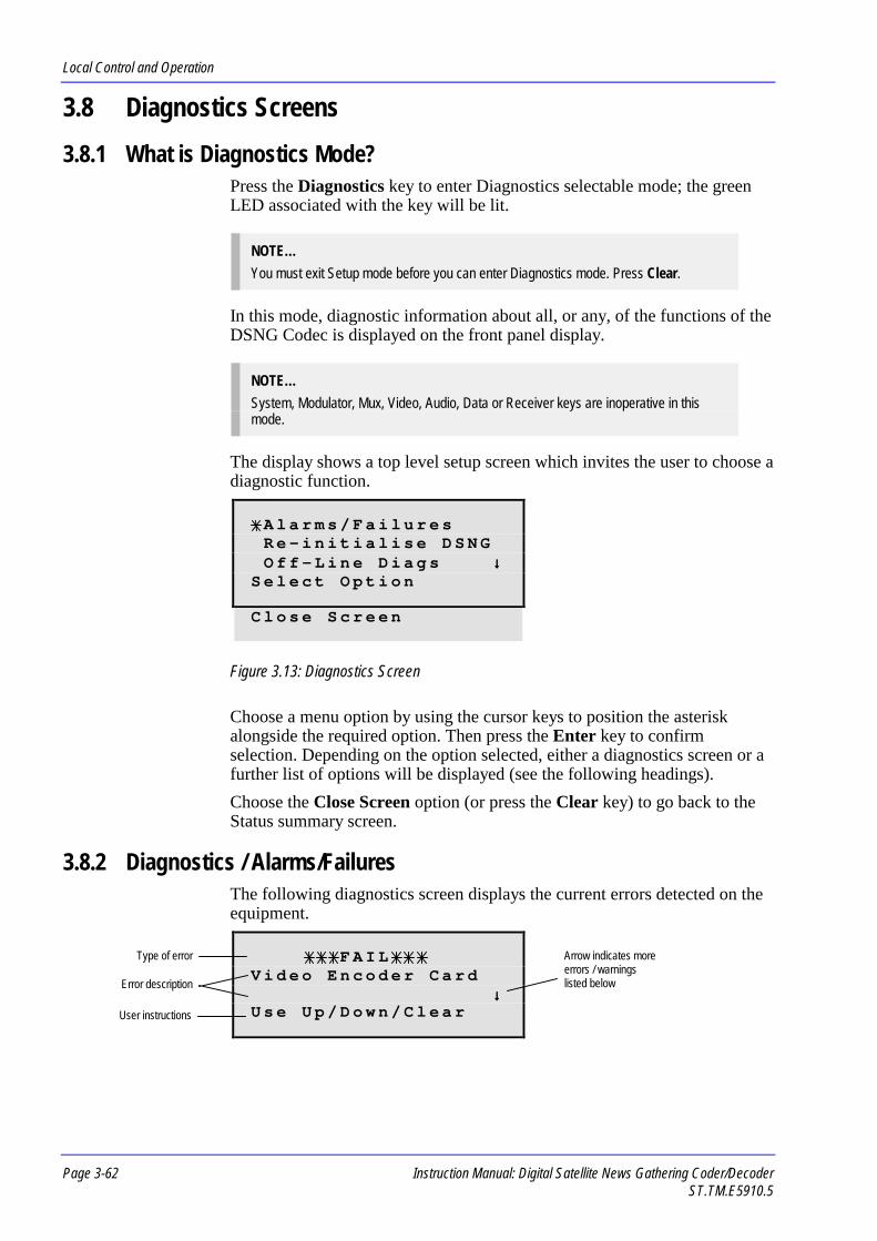
Local Control and Operation
Page 3-62 Instruction Manual: Digital Satellite News Gathering Coder/DecoderST.TM.E5910.5
3.8 Diagnostics Screens3.8.1 What is Diagnostics Mode?
Press the Diagnostics key to enter Diagnostics selectable mode; the greenLED associated with the key will be lit.
NOTE…You must exit Setup mode before you can enter Diagnostics mode. Press Clear.
In this mode, diagnostic information about all, or any, of the functions of theDSNG Codec is displayed on the front panel display.
NOTE…System, Modulator, Mux, Video, Audio, Data or Receiver keys are inoperative in thismode.
The display shows a top level setup screen which invites the user to choose adiagnostic function.
A l a r m s / F a i l u r e sR e - i n i t i a l i s e D S N GO f f - L i n e D i a g s ↓↓↓↓
S e l e c t O p t i o n
C l o s e S c r e e n
Figure 3.13: Diagnostics Screen
Choose a menu option by using the cursor keys to position the asteriskalongside the required option. Then press the Enter key to confirmselection. Depending on the option selected, either a diagnostics screen or afurther list of options will be displayed (see the following headings).Choose the Close Screen option (or press the Clear key) to go back to theStatus summary screen.
3.8.2 Diagnostics / Alarms/FailuresThe following diagnostics screen displays the current errors detected on theequipment.
F A I LV i d e o E n c o d e r C a r d
↓↓↓↓U s e U p / D o w n / C l e a r
Type of error Arrow indicates moreerrors / warningslisted belowError description
User instructions

Local Control and Operation
Instruction Manual: Digital Satellite News Gathering Coder/Decoder Page 3-63ST.TM.E5910.5
Use the ∧∧∧∧ and ∨∨∨∨ cursor keys to scroll through the list of error messages inthe event that several errors are detected (see Chapter 6, Fault Finding for alist of error and warning messages and the action necessary to restoreoperation). If the equipment is functioning correctly, the display reads Noerrors. Press the Clear key to return to the top level Diagnostics screen.
3.8.3 Diagnostics / Re-initialise DSNGThe following option performs a restart of the encoding circuitry and re-enabling the output.
R e - i n i t i a l i s i n gD S N G
3.8.4 Diagnostics / Off-Line DiagsThe following diagnostics screen displays options for testing the functionalareas of the DSNG Codec.
IMPORTANT NOTE…Upon entry into this menu, the output is switched off.
C o m p l e t e S e l f - T e s tM o d u l a t o rM u l t i p l e x e r ( M u x ) ↓↓↓↓
S e l e c t O p t i o n
V i d e oA u d i oD a t aR e c e i v e rF r o n t P a n e l D i s p l yK e y b o a r dF r o n t P a n e l L E D sA l a r m R e l a yF a i l R e l a yC l o s e S c r e e n
Choose a menu option by using the cursor keys to position the asteriskalongside the required option. Then press the Enter key to confirmselection. A diagnostics screen will be displayed (see following headings).Choose the Close Screen option (or press the Clear key) to go back to theDiagnostics screen.
Diagnostics / Off-Line Diags / Complete Self-TestThe following diagnostics screen enables a complete test of the followingfunctional areas:

Local Control and Operation
Page 3-64 Instruction Manual: Digital Satellite News Gathering Coder/DecoderST.TM.E5910.5
Modulator Multiplexer Video Audio DataThe complete self-test takes approximately 3.5 minutes and can not becancelled once selected. These tests may be performed separately if required(see headings below).Press the Enter key to run through the functional tests in sequence.
Diagnostics / Off-Line Diags / ModulatorThe following diagnostics screen enables a test of the modulator functions tobe performed. Initially, a screen is displayed which shows the hardware(card number) and software (version number) to be tested.
I F M o d u l a t o rH a r d w a r e i d : S 5 9 0 0V e r s i o n N o : BA n y K e y t o C o n t i n u e
Press any key to start the test and display the results.
I F M o d u l a t o rP A S S
A n y K e y t o C o n t i n u e
Press any key to return to the Diagnostics / Off-Line Diags screen.
Diagnostics / Off-Line Diags / Multiplexer (Mux)The following diagnostics screen enables a test of the multiplexing functionsto be performed. Initially, a screen is displayed which shows the hardware(card number) and software (version number) to be tested.
M u x M o d C a r dH a r d w a r e i d : S 5 8 9 8S o f t w a r e : 2 . 0A n y K e y t o C o n t i n u e
Press any key to start the test and display the results.
M u x M o d C a r dP A S S
A n y K e y t o C o n t i n u e
Press any key to return to the Diagnostics / Off-Line Diags screen.
Test Results(PASS or error messageand FAIL screens)
Test Results(PASS or error messageand FAIL screens)

Local Control and Operation
Instruction Manual: Digital Satellite News Gathering Coder/Decoder Page 3-65ST.TM.E5910.5
Diagnostics / Off-Line Diags / VideoThe display shows a top level setup screen which invites the user to choose adiagnostic function.
V i d e o E n c o d e rV i d e o I n p u tC l o s e S c r e e n
S e l e c t O p t i o n
Choose a menu option by using the cursor keys to position the asteriskalongside the required option. Then press the Enter key to confirmselection. A diagnostics screen will be displayed (see following headings).Choose the Close Screen option (or press the Clear key) to go back to theStatus summary screen.Diagnostics / Off-Line Diags / Video / Video EncoderThe following diagnostics screen enables a test of the video encodingfunctions to be performed. The Video Encoder diagnostics takeapproximately 3 minutes and can not be cancelled once selected. The card tobe tested is initially interrogated.
T e s t i n g V i d e oE n c o d e r . . .
P l e a s e W a i t
V i d e o E n c o d e r C a r dH a r d w a r e i d : S 5 4 3 0S o f t w a r e : 1 . 5A n y K e y t o C o n t i n u e
Press any key to initiate a simple functional test of the card.
V i d e o E n c o d e r C a r dS t a t u s : P A S S
A n y K e y t o C o n t i n u e
Press any key to start a rigorous test of the Encoder ICs test.
T e s t i n g V i d e oE n c o d e r I C sA : P A S S I C AP l e a s e W a i t –
V i d e o E n c o d e r C a r dP A S S
A n y K e y t o C o n t i n u e
Test Results(PASS or error messageand FAIL screens)
Test Results(PASS or error messageand FAIL screens)
Rotating segmentindicates that the test isprogressing

Local Control and Operation
Page 3-66 Instruction Manual: Digital Satellite News Gathering Coder/DecoderST.TM.E5910.5
Press any key to return to the Diagnostics / Off-Line Diags / Video screen.
Diagnostics / Off-Line Diags / Video / Video InputThe following diagnostics screen enables a test of the video input functionsto be performed. The card to be tested is initially interrogated.
T e s t i n g V i d e oI n p u t . . .
P l e a s e W a i t
V i d e o I n p u t C a r dH a r d w a r e i d : S 5 4 2 4S o f t w a r e : 1 . 7A n y K e y t o C o n t i n u e
Press any key to initiate a simple functional test of the card.
V i d e o I n p u t C a r dS t a t u s : P A S S
A n y K e y t o C o n t i n u e
Press any key to return to the Diagnostics / Off-Line Diags / Video screen.
Diagnostics / Off-Line Diags / AudioThe following diagnostics screen enables a test of the audio functions to beperformed. The card to be tested is initially interrogated.
T e s t i n g A D T C a r d( A u d i o ) . . .
P l e a s e W a i t
A u d i o ( A D T ) C a r dH a r d w a r e i d : S 5 4 2 7S o f t w a r e : 1 . 6A n y K e y t o C o n t i n u e
Press any key to start the test and display the results.
T e s t i n g A u d i oC h a n n e l A . . .
P l e a s e W a i t
Test Results(PASS or error messageand FAIL screens)
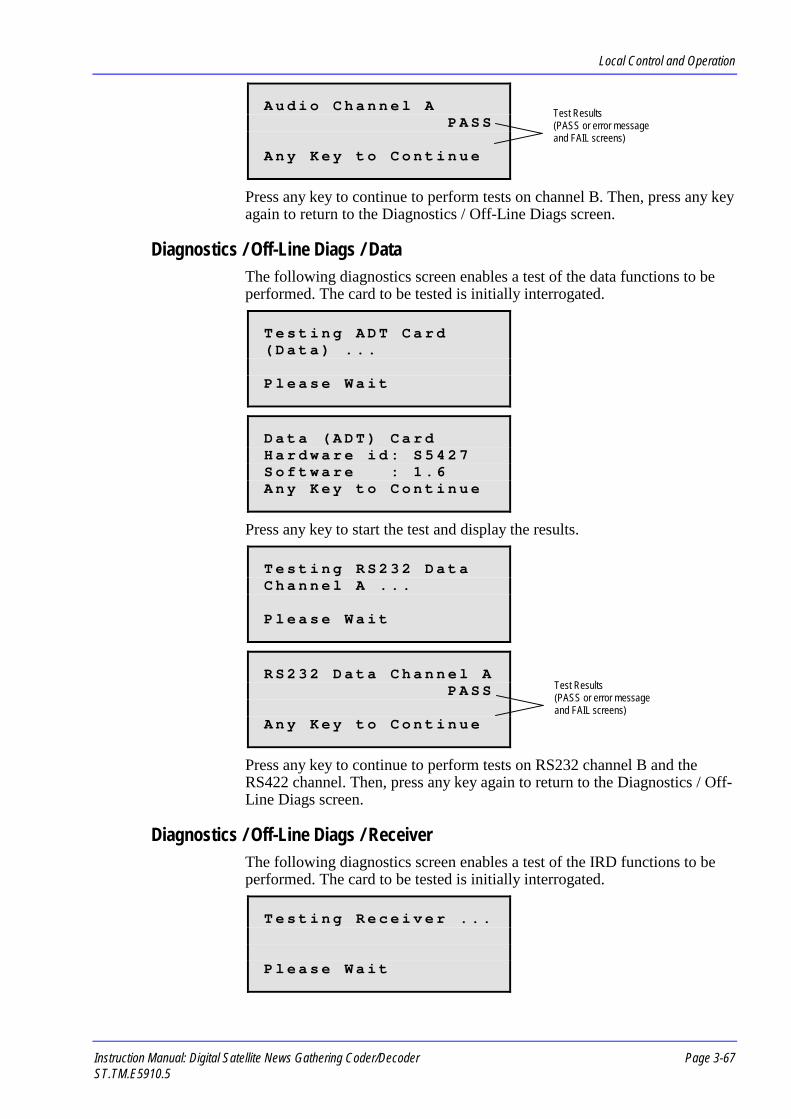
Local Control and Operation
Instruction Manual: Digital Satellite News Gathering Coder/Decoder Page 3-67ST.TM.E5910.5
A u d i o C h a n n e l AP A S S
A n y K e y t o C o n t i n u e
Press any key to continue to perform tests on channel B. Then, press any keyagain to return to the Diagnostics / Off-Line Diags screen.
Diagnostics / Off-Line Diags / DataThe following diagnostics screen enables a test of the data functions to beperformed. The card to be tested is initially interrogated.
T e s t i n g A D T C a r d( D a t a ) . . .
P l e a s e W a i t
D a t a ( A D T ) C a r dH a r d w a r e i d : S 5 4 2 7S o f t w a r e : 1 . 6A n y K e y t o C o n t i n u e
Press any key to start the test and display the results.
T e s t i n g R S 2 3 2 D a t aC h a n n e l A . . .
P l e a s e W a i t
R S 2 3 2 D a t a C h a n n e l AP A S S
A n y K e y t o C o n t i n u e
Press any key to continue to perform tests on RS232 channel B and theRS422 channel. Then, press any key again to return to the Diagnostics / Off-Line Diags screen.
Diagnostics / Off-Line Diags / ReceiverThe following diagnostics screen enables a test of the IRD functions to beperformed. The card to be tested is initially interrogated.
T e s t i n g R e c e i v e r . . .
P l e a s e W a i t
Test Results(PASS or error messageand FAIL screens)
Test Results(PASS or error messageand FAIL screens)

Local Control and Operation
Page 3-68 Instruction Manual: Digital Satellite News Gathering Coder/DecoderST.TM.E5910.5
R e c e i v e r ( I R D ) C a r dH a r d w a r e i d : S 5 9 0 2S o f t w a r e : 1 . 9 . N SA n y K e y t o C o n t i n u e
Press any key to display further information about the IRD.
R e c e i v e r ( I R D ) C a r dS T 9 0 S o f t w a r e : 4 . 1
A n y K e y t o C o n t i n u e
Press any key to start the test and display the results.
R e c e i v e r ( I R D ) C a r dP A S S
A n y K e y t o C o n t i n u e
Press any key to return to the Diagnostics / Off-Line Diags / Receiverscreen.
Diagnostics / Off-Line Diags / Front Panel DisplyThe following diagnostics screen enables a test of the front panel display tobe performed. The test sends various patterned blocks, both stationary andmoving, to the display in order for the user to be able to check whether anyareas or pixels of the screen are no longer functioning. The test takesapproximately 12 seconds to complete.
The test sequences runs automatically and returns to the Diagnostics / Off-Line Diags screen upon completion.
Diagnostics / Off-Line Diags / KeyboardThe following diagnostics screen displays the name of the last front panelkey pressed.
L a s t K e y P r e s s e d :S e t u p
C l e a r t o E x i t
Press any front panel key to see its name identified on this display. Keypresses are accompanied by the beeper. Press Clear followed by Enter inorder to exit and return to the Diagnostics / Off-Line Diags screen.
Test Results(PASS or error messageand FAIL screens)

Local Control and Operation
Instruction Manual: Digital Satellite News Gathering Coder/Decoder Page 3-69ST.TM.E5910.5
Diagnostics / Off-Line Diags / Front Panel LEDsThe following diagnostics screen enables a test of all the front panel LEDsto be performed. The test takes approximately 20 secondes to complete.
L E D t e s tA l l O n
P l e a s e W a i t
The screen displays the corresponding key name which is being lit. TheLEDs are lit in sequence around the front panel in order for the user to beable to check whether any LEDs are no longer functioning. The test startswith the mode keys, the function keys, then the status LEDs at the bottomleft-hand side of the equipment. The test sequences runs automatically andreturns to the Diagnostics / Off-Line Diags screen upon completion.
Diagnostics / Off-Line Diags / Alarm RelayThe following diagnostics screen enables a test of the Alarm and Fail relaysto be performed. The relay is toggled ON and OFF approximately every halfsecond. The click of the relay can be heard, plus the front panel Alarm LEDis lit corresponding to the ON condition.
A L A R M R e l a y O N
A n y K e y t o C o n t i n u e
Press any key to continue to test the FAIL relay in the same way as theAlarm relay described above. Connections to the relay contacts are availableat the rear panel RESET / STATUS connector (see Chapter 2, Installationfor connector details).Press any key again to return to the Diagnostics / Off-Line Diags screen.

Local Control and Operation
Page 3-70 Instruction Manual: Digital Satellite News Gathering Coder/DecoderST.TM.E5910.5
BLANK

Instruction Manual: Digital Satellite News Gathering Coder/Decoder Page 4-1ST.TM.E5910.5
Chapter 44. Equipment Description
Contents4.1 Introduction ...................................................................4-3
4.2 Video Coding.................................................................4-34.2.1 General ................................................................4-34.2.2 Frame Types........................................................4-34.2.3 Frame Sequence .................................................4-4
4.3 Audio Coding.................................................................4-5
4.4 Data Handling ...............................................................4-5
4.5 Codec Functional Description .......................................4-54.5.1 Overview..............................................................4-54.5.2 Codec Enclosure..................................................4-74.5.3 Power Supply Unit ...............................................4-74.5.4 Backplane S5882.................................................4-74.5.5 Audio, Data and Teletext Card S5427 .................4-84.5.6 Video Input Card S5424.......................................4-94.5.7 MPEG-2 Video Encoder Card S5430 ................4-104.5.8 Multiplexer / Baseband Modulator Card
S5898................................................................4-114.5.9 IF Modulator Card S5900...................................4-124.5.10 Integrated Receiver-Decoder Card S5902.......4-13
List of IllustrationsFigure 4.1: Coding Scheme Block Diagram................................... 4-3Figure 4.2: DSNG Codec Block Diagram....................................... 4-6Figure 4.3: Rear Panel LEDs ......................................................... 4-7
List of TablesTable 4.1: Video Input Card LEDs ................................................. 4-9Table 4.2: MPEG-2 Video Encoder Card LEDs ........................... 4-10Table 4.3: Multiplexer / Baseband Modulator Card LEDs............ 4-11Table 4.4: IF Modulator Card LEDs ............................................. 4-12Table 4.5: Integrated Receiver-Decoder Card LEDs ................... 4-13

Equipment Description
Page 4-2 Instruction Manual: Digital Satellite News Gathering Coder/DecoderST.TM.E5910.5
BLANK

Equipment Description
Instruction Manual: Digital Satellite News Gathering Coder/Decoder Page 4-3ST.TM.E5910.5
4.1 IntroductionThis chapter provides a simplified overview of the DSNG Codec andexplains the functions of each of the cards. A description of the on-cardLEDs visible at the rear panel is also given here.
4.2 Video Coding
4.2.1 GeneralThe fundamental objective of the coding scheme is to exploit informationredundancy in the input video signal to minimise the amount of datarequired for successful transmission. To achieve this, the DSNG Codec usesa number of interactive processes. The resultant compressed bit-streamsyntax conforms to the ISO 13818 standard. An explanation of the overallcoding strategy follows.
4.2.2 Frame TypesCoding operates on a frame (or picture) based principle. There are three frametypes:
I (intra-coded frames),
P (predicted frames),
B (bi-directionally predicted frames).
P and B frames are known as inter-coded frames. Coding of I frames occurswithout reference to any other frames. P frames use motion compensationfrom a previous I or P frame. B frames are coded using motion compensationfrom a previous and/or a future I or P frame. Thus, a coding scheme maycontain a mix of I, B and P. Figure 4.1 illustrates the coding process.
Figure 4.1: Coding Scheme Block Diagram
Pre-processingDigital/
AnalogueVideo In
Predicted Frame andDifference Signal
Generation
Common PathProcessing Functions
(DCT codingQuantisation
VLC encoding)
CompressedVideo Out
MotionVectors
Intra
Inter
Error
I Frames →
B or P Frames →

Equipment Description
Page 4-4 Instruction Manual: Digital Satellite News Gathering Coder/DecoderST.TM.E5910.5
The motion-compensated-predicted frame is subtracted from the currentframe to produce a frame difference or prediction-error value. Thisprediction-error value is coded instead of the complete frame information,thus affording a considerable saving in bit-rate; this mode of operation isknown as "inter-frame" coding. The prediction-error information isaugmented by motion vector information which is also coded and enablesrecovery of the current complete frame information by a Decoder.
The I frames and prediction-error values are processed in blocks of 8x8pixels which are first transformed by a Discrete Cosine Transform (DCT).For typical images, the distribution of the coefficients is not uniform due tospatial redundancy, and the energy tends to be concentrated into the lowfrequency coefficients. The number of bits required for a block is reduced bynot transmitting the near-zero coefficients and by quantising the remainingones. Quantisation results in a reduction of the number of possible values tobe transmitted. These values are then entropy-coded using a Variable LengthCode (VLC). The VLC allocates codes which have different lengthdepending upon the probability with which they are expected to occur.
NOTE…
The motion estimation and DCT coding can be field or frame based to achieve a bettercoding efficiency.
4.2.3 Frame SequenceDepending on the coding mode used, P or B frames are produced for intercoding.
The regular transmission of an I frame provides a regular reference fromwhich predicted frames can be generated, thereby ensuring that predictionsdo not become wildly inaccurate and give a starting point for decoding.
The run of frames from the start of an I frame to the start of the next I frameis known as a group of pictures (GOP). Each GOP is identified by a uniqueheader.
The GOP structure for PAL is fixed in length at 12 frames, and can be of thefollowing format:
IPPPPPPPPPPPI, for non-B frame operation (IP)
IBPBPBPBPBPBI, for operation with B frames (IPB)
IBBPBBPBBPBBI, for successive B frames (IBBP)
The GOP structure for NTSC is either 14 or 15 frames, and can be of thefollowing format:
IPPPPPPPPPPPI, for non-B frame operation (IP) - 15 frames
IBPBPBPBPBPBI, for operation with B frames (IPB) - 14 frames
IBBPBBPBBPBBI, for successive B frames (IBBP) - 15 frames

Equipment Description
Instruction Manual: Digital Satellite News Gathering Coder/Decoder Page 4-5ST.TM.E5910.5
4.3 Audio CodingAudio encoding is to the MPEG-2 encoding standard ISO/IEC 13818-3(layer 1 or 2) at a sampling rate of 48 kHz.
The spectrum of the received broad-band audio signal is divided into sub-bands of equal bandwidth by filtering. Each of these sub-bands is separatelysampled and quantised to convert the input analogue signal into a sequenceof discrete sample values. The samples associated with each sub-band areseparately coded according to the psycho-acoustic properties of the humanauditory system. Critical regions are coded more accurately, with less bitsbeing assigned to frequencies at which the ear is less sensitive. Coding isalso dependent on dynamic information such as audio masking, in which aloud sound at one frequency dominates over any quieter sounds at adjacentfrequencies.
Adaptive Differential Pulse Code Modulation (ADPCM) techniques areused to reduce the bit-rate by coding the difference values betweensuccessive samples rather than absolute values. Quantisation step size isadjusted depending on the magnitude of the difference value: a rapid changeproduces a coarse approximation followed by smaller, more precisesuccessive samples.
For all coding modes (stereo, mono, dual mono and joint stereo) the digitallycoded bits are formatted into distinct frames, each of which contains aheader which defines the frame in detail (coding scheme, mode, bit-rate,etc.). Since the number of useful bits varies depending on the psycho-acoustic properties of the corresponding sound samples, the frame can bepadded. The resultant encoded audio output bit-rate is software selectable inthe range 32 kHz to 384 kHz, depending on the mode selected (see Chapter1, Introduction for table of supported bit-rates).
4.4 Data HandlingThe synchronous and asynchronous data channels provided by the Encoderare simple bit-pipes and are not coded in any way. This is due to the factthat the nature of the data to be transmitted is expected to be different forindividual customers and, therefore, a suitable coding scheme cannot beprovided with any guarantee of performance.
4.5 Codec Functional Description
4.5.1 OverviewEither analogue composite / component, or digital parallel / serial video maybe applied to the Video Input Card (Figure 4.2). The Video Input Cardsynchronises the input video to an internal reference clock and digitises thevideo signal to a Y/Cb/Cr 656 format and provides down-sampling, ifrequired.
The MPEG-2 Video Encoder Card takes in the digitised video signal andprocesses it to a compressed encoded bit-stream in accordance with theMPEG-2 video specification.

Equipment Description
Page 4-6 Instruction Manual: Digital Satellite News Gathering Coder/DecoderST.TM.E5910.5
Coded video information (the amount of redundant information removedcan be as high as 95%) is routed to the Multiplexer / Baseband ModulatorCard were it is combined with coded audio and data (uncoded) informationfrom the Audio, Data and Teletext (ADT) Card.
The Multiplexer / Baseband Modulator Card provides a DVB-compliantmultiplexed output of the video, audio and data signals and inserts userConditional Access (CA) and Programme Specific Information (PSI). Theoutput is routed directly to an output connector and to the IRD Card. Data ispassed through a convolutional encoder and a pulse shaping filter (√35%cosine roll-off) before being routed to the IF Modulator Card. The card alsoprovides the user control interface to the front panel for local control, and toa rear panel connector for remote control.
The IF Modulator provides the satellite conditioning to the multiplexedMPEG-2 / DVB transport packets. A 70 / 140 MHz carrier is QPSKmodulated with the data output for routing to Up-converter and HPA.
The IF output may be monitored locally by the Integrated Receiver-Decoder(IRD) Card (M2/ESN/SNGB option only) which provides the necessarydemodulation and demultiplexing to restore the original video, audio anddata signals. Additionally, the IRD also accepts an L-band input or anunmodulated DVB parallel input.
Figure 4.2: DSNG Codec Block Diagram
S5424Video Input Card
PARALLELDIGITAL
SERIAL DIGITAL
ANALOGUECOMPOSITE
ANALOGUECOMPONENT
AUDIO A (L/R)
AUDIO B (L/R)
RS422
RS232 CHA/CHB
TestPacket
Generator
S5430MPEG-2 VideoEncoder Card
S5898Multiplexer /Baseband
Modulator Card
S5427Audio, Data Card
S5900IF Modulator Card
S5902Integrated
Receiver-DecoderCard (option)
CLK
YCrCb
CONTROL
RESET /STATUS
V
A
D
Test PatternGenerator
CAPSIIF OUT
IF MON 1
IF MON 2
BB OUT
BB IN
L-BAND IN
IF IN
VIDEO OUT
AUDIO OUT
DVBProcessing

Equipment Description
Instruction Manual: Digital Satellite News Gathering Coder/Decoder Page 4-7ST.TM.E5910.5
4.5.2 Codec EnclosureThe DSNG Codec is constructed in a 5U enclosure. Mounted at the side ofthe enclosure are six 24 V d.c. fans for general cooling. The rear panel(Figure 4.3) of the enclosure has holes and slots cut into it to allow LEDs onthe cards to show through (see following headings for a description of eachof the LEDs).
4.5.3 Power Supply UnitThe power supply unit used in this equipment is autosensing, accepting aninput in the range 100-120 V a.c., or 220-240 V a.c., 45-440 Hz (see AnnexB, Technical Specification for a details) to provide the regulated voltagesupplies required by the cards in the DSNG Codec.
4.5.4 Backplane S5882The 5U Backplane is mounted toward the front of the enclosure. All cardsmate with the Backplane to allow inter-card communications and powersupply distribution.
Figure 4.3: Rear Panel LEDs
On-Card LED indicators

Equipment Description
Page 4-8 Instruction Manual: Digital Satellite News Gathering Coder/DecoderST.TM.E5910.5
4.5.5 Audio, Data and Teletext Card S5427The Audio, Data and Teletext Card is fitted in slot position 1 (top) of theBackplane. It performs the following functions:
Provides an interface between the non-video sources: audio andsynchronous / asynchronous data, and the Multiplexer/BasebandModulator Card.
Accepts up to four analogue audio inputs, digitises and compresses toMPEG-2 standard, or accepts AES/EBU digital inputs.
Accepts two RS-232 asynchronous data channels running at up to 9600baud (not compressed).
Accepts one RS-422 synchronous data channel at up to 1 Mbit/s (notcompressed).
NOTE…
The teletext feature of this card is not supported in this application.
There are no LED or other indicators displayed at the rear panel.

Equipment Description
Instruction Manual: Digital Satellite News Gathering Coder/Decoder Page 4-9ST.TM.E5910.5
4.5.6 Video Input Card S5424The Video Input Card is fitted in slot position 2 of the Backplane. Itperforms the following functions:
Provides a single video input channel to the MPEG-2 Video EncoderCard, accepting a variety of input types, and conditions the input inpreparation for video encoding
Converts analogue PAL/NTSC composite video signal into digitalYCbCr component CCIR (ITU-R) 656 format
Converts analogue YUV or Betacam component video signals intodigital YCbCr component CCIR (ITU-R) 656 format
Accepts parallel digital video input CCIR (ITU-R) 656 directly
De-serialises serial digital video input CCIR (ITU-R) 656
Incorporates polyphase filters to enable the resolution to be changed.Resolutions supported are 352, 480, 544 and 704 (horizontal)
Provides loss of video detection which results in switching to aninternally-generated test pattern or freeze frame (selectable)
Synchronises input video frames to the 27 MHz system clock referenceprovided by the Multiplexer / Baseband Modulator Card.
Provides internal Test Pattern Generator which may be used as thevideo source for testing purposes
Various LEDs are located along the edge of the card to indicate the cardstatus and functionality.
Table 4.1: Video Input Card LEDs
Annotation Colour Function
+15V Green Lights to indicate supply present
+5V Green Lights to indicate supply present.
-5V Green Lights to indicate supply present
-15V Green Lights to indicate supply present
525 Yellow Lights to indicate equipment configured to accept a 525 line signal.
625 Yellow Lights to indicate equipment configured to accept a 625 line signal.
COMPOSITE Yellow Lights to indicate equipment configured to accept an analogue compositevideo signal.
YUV Yellow Lights to indicate equipment configured to accept an analogue componentvideo signal.
656 PAR. Yellow Lights to indicate equipment configured to accept a parallel digital videosignal.
SERIAL Yellow Lights to indicate equipment configured to accept a serial digital video signal.
TPG ON Yellow Lights to indicate that the internal Test Pattern Generator is active.
SYS CLK Yellow Lights to indicate that video is synchronised with the system reference clock.
SOURCE CLK Yellow Lights to indicate that video is synchronised with the video source itself.
+5V
-5V
+15V
-15V
525625COMPOSITEYUV656 PAR.SERIALTPG ONSYS CLKSOURCE CLK

Equipment Description
Page 4-10 Instruction Manual: Digital Satellite News Gathering Coder/DecoderST.TM.E5910.5
4.5.7 MPEG-2 Video Encoder Card S5430The MPEG-2 Video Encoder Card is fitted in slot position 3 of theBackplane. It performs the following functions:
Receives digital YCrCb component CCIR (ITU-R) 656 format videoinput from the Video Input Card and compresses it according to theMPEG-2 standard to minimise the required bit-rate to transmit the videoinformation
Provides the MPEG-2 video packetised elementary stream to theMultiplexer / Baseband Modulator Card.
Various LEDs are located along the edge of the card to indicate the cardstatus and functionality.
Table 4.2: MPEG-2 Video Encoder Card LEDs
Annotation Colour Function
+12V Green Lights to indicate supply present
+5V Green Lights to indicate supply present.
-5V Green Lights to indicate supply present
INIT Green Lights to indicate that the Encoder has been initialised correctly and theinitial MPEG-2 bit-stream has been output. This LED should be ON whenthe Encoder is running.
U-FLOW Red Lights to indicate underflow of the Encoder buffer.
O-FLOW Red Lights to indicate overflow of the Encoder buffer.
XIBOOT Yellow Lights to indicate that the output stage of the card has been configuredcorrectly. This LED should always be ON.
+5V
-5V
+12V
INITU-FLOWO-FLOWXIBOOT

Equipment Description
Instruction Manual: Digital Satellite News Gathering Coder/Decoder Page 4-11ST.TM.E5910.5
4.5.8 Multiplexer / Baseband Modulator Card S5898The Multiplexer / Baseband Modulator Card is fitted in slot position 4 of theBackplane. It performs the following functions:
Receives / stores video data from the Video Encoder Card and audio /data information from the ADT Card and multiplexes them togetherinto a single baseband transport stream
Forms 188 byte MPEG-2 transport stream packets by adding headers tothe 184 bytes of data received from the requested source (video, audioand data). Inserts NULL packets if no data is available
Data scrambling
Baseband transport stream output to parallel DVB interface
Provides serial transport stream output to the IRD
Provides digital baseband signals to the IF Modulator
Spectral Scrambling and Sync Inversion
Reed-Solomon (204,188) forward error correction and Interleaving
Convolutional Forward Error Correction (FEC)
Pulse shaping filter (√35% cosine roll-off)
Controls the output of CA and PSI packets into the transport stream.
Controls the reset for the entire Codec
Real Time Clock, Temperature Sensor and Front Panel Interface
Various LEDs, indicating card status and functionality, are placed along theedge of the card and are visible through cut-outs in the rear panel.
Table 4.3: Multiplexer / Baseband Modulator Card LEDs
Annotation Colour Function
+15V Green Lights to indicate supply present
+5V Green Lights to indicate supply present
-5V Green Lights to indicate supply present
XIBOOT Yellow Lights to indicate Mux circuitry is correctly configured. Should always be ON.
NULL Yellow Lights to indicate that the currently transmitted packet is a null. Should always beON. Once the system is operating, the LED may glow dimly due to occasionalnulls. If this LED is completely OFF the Multiplexer is in test mode or failed.
BUS Yellow Should always be ON if any of the input sources are active. LED brightnessdepends on the relative number of non null packets sent. If this LED is OFF,there is no information from other sources passing through the Multiplexer.
FAIL Red Lights in conjunction with energising FAIL relay (contacts at RESET/STATUSconnector). A software-controlled indication of problems in the system.
ALARM Red Lights in conjunction with the energising of the ALARM relay (contacts availableat the RESET / STATUS connector). This is a software controlled indication ofless serious (than FAIL) problems in the system.
RESET Red Lights when the external RESET is asserted.
FIFO Red Lights if there is a problem with the clock circuitry on the Multiplexer / Modulatorinterface. This LED should always be off when the equipment is set for IFoutput, but may light for a brief period during configuration changes to theMultiplexer / Modulator, and be on when set for baseband output.
CYPHER Red Lights when the data at the input to the cypher module is of an incorrect format(missing hex 47 sync bytes). This LED should always be OFF.
+5V
-5V
+12V
XIBOOTNULLBUSFAILALARMRESETFIFOCYPHER

Equipment Description
Page 4-12 Instruction Manual: Digital Satellite News Gathering Coder/DecoderST.TM.E5910.5
4.5.9 IF Modulator Card S5900The IF Modulator Card is fitted in slot position 5 of the Backplane. Itperforms the following functions:
Receives digital baseband signals from the Multiplexer / BasebandModulator Card and modulates it for transmission as an IF signal touplink equipment.
Modulates a 70 or 140 MHz carrier with the data output signal usingQuadrature Phase Shift Keying (QPSK)
IF output frequency control over the ranges 70 MHz ± 20 MHz and140 MHz ± 40 MHz in 125 kHz steps
IF output power level control over the range −27 dBm to +5 dBm in0.1 dB steps
Provides the main IF modulated output for routing to the Up-converter /High Power Amplifier equipment
Provides two modulated IF monitoring outputs, one of which isintended to provide a dedicated IF signal feed to the IRD Card (S5902)
Various LEDs are located along the front edge of the cards to indicate cardstatus and functionality.
Table 4.4: IF Modulator Card LEDs
Annotation Colour Function
+15V Green Lights to Indicate supply is present.
+5V Green Lights to Indicate supply is present.
-5V Green Lights to Indicate supply is present.
-15V Green Lights to Indicate supply is present.
ALC Red Automatic level control of the IF signal is not levelled.
SYNTH Red Synthesiser 1 or 2 out of lock.
+5V
-5V
+15V
-15V
ALCSYNTH

Equipment Description
Instruction Manual: Digital Satellite News Gathering Coder/Decoder Page 4-13ST.TM.E5910.5
4.5.10 Integrated Receiver-Decoder Card S5902The Integrated Receiver-Decoder Card (M2/ESN/SNGB option only) isfitted in slot position 6 of the Backplane. It performs the followingfunctions:
Provides a local monitoring facility for the DSNG encoded, multiplexedand modulated video, audio and data channels. The DSNG output canbe monitored at the following stages: baseband, IF or L-band. Thisfacility may also be used to monitor other unrelated baseband or L-bandtransmissions
Demodulates digital QPSK modulated IF signals
Provides Viterbi and Reed-Solomon (204, 188) decoding
Provides descrambling and demultiplexing to restore original video,audio and data signals
Provides video, audio channel decoding, single synchronous andasynchronous data monitoring outputs
Provides a tuneable frequency-synthesised local oscillator for the down-conversion of the L-band input
Generates a dc supply voltage for a Low Noise Block (LNB) which maybe connected via the L-band input
Various LEDs are located along the edge of the cards to indicate card statusand functionality.
Table 4.5: Integrated Receiver-Decoder Card LEDs
Annotation Colour Function
+15V Green Lights to Indicate supply is present.
+5V Green Lights to Indicate supply is present.
-5V Green Lights to Indicate supply is present.
-15V Green Lights to Indicate supply is present.
+30V Green Lights to Indicate supply is present.
LNB POWER Yellow Lights to indicate that the dc power supply is enabled on the L-bandconnector.
SYNC LOCK Green Lights to indicate lock with the transport stream.
ALARM Red Lights to indicate an alarm condition within the IRD. May also light ifeither baseband input is used in the absence of L-band or IF inputs.
CLOCK UNLOCK Red Lights to indicate symbol rate clock synchronisation has been lost.May also light if either baseband input is used in the absence of L-band or IF inputs.
CARRIER UNLOCK Red Lights to indicate that carrier synchronisation has been lost. Mayalso light if either baseband input is used in the absence of L-bandor IF inputs.
+5V
-5V
+15V
-15V
LNB POWER
SYNC LOCK
ALARM
CLOCK UNLOCK
CARRIER UNLOCK
+30V

Equipment Description
Page 4-14 Instruction Manual: Digital Satellite News Gathering Coder/DecoderST.TM.E5910.5
BLANK

Instruction Manual: Digital Satellite News Gathering Coder/Decoder Page 5-1ST.TM.E5910.5
Chapter 55. Preventive Maintenance and Fault-finding
Contents5.1 Preventive Maintenance ...............................................5-3
5.1.1 Routine Inspection ..............................................5-3Cooling Fans .......................................................5-3Rear Panel LEDs.................................................5-3
5.1.2 Cleaning..............................................................5-35.1.3 Servicing .............................................................5-3
Servicing..............................................................5-3Damage Requiring Service..................................5-3Replacement Parts ..............................................5-4Checks on Completion of Servicing.....................5-4
5.1.4 Maintenance .......................................................5-4Warranty ..............................................................5-4Levels of Maintenance Support ...........................5-5
5.2 Fault-finding ..................................................................5-65.2.1 Maintenance Philosophy.....................................5-65.2.2 Fault Diagnosis and Rectification for an
Operator..............................................................5-65.2.3 Error Reporting ...................................................5-7
Categories of Error ..............................................5-7Alarm and Fail Relays .........................................5-7Error Masking and Selection ...............................5-8Error Messages ...................................................5-8
5.2.4 Front Panel Display Problems ..........................5-12Introduction........................................................5-12Screen is Blank..................................................5-12Area of the Screen is Permanently Blank orLit.......................................................................5-12Front Panel LED(s) / Key(s) are NotFunctioning ........................................................5-12Setup and / or Diagnostics Screens Cannotbe Accessed ......................................................5-12Password Does Not Work / Forgotten ...............5-12
Parameters Cannot be Adjusted ....................... 5-13Commands are not Carried Out ........................ 5-13
5.2.5 Video Channel Problems.................................. 5-145.2.6 Audio Channel Problems.................................. 5-155.2.7 Data Channel Problems ................................... 5-165.2.8 Alarm(s) Indicated but Signals are Good.......... 5-175.2.9 Power Supply Problems/LEDs Unlit ................. 5-17
Introduction ....................................................... 5-17Power LED Unlit ................................................ 5-17Rear Panel DC Supply LED(s) Unlit.................. 5-18Alarm LED Unlit when Alarm Occurs ................ 5-18Fan(s) Not Working/Overheating ...................... 5-19
5.3 Disposing of this Equipment ....................................... 5-195.3.1 General............................................................. 5-195.3.2 Lithium Batteries............................................... 5-19
List of IllustrationsFigure 5.1: Typical Error Message .................................................5-8
List of TablesTable 5.1: Error Messages.............................................................5-8Table 5.2: Video Channel Troubleshooting..................................5-14Table 5.3: Audio Channel Troubleshooting..................................5-15Table 5.4: Data Channel Troubleshooting ...................................5-16Table 5.5: Power LED Troubleshooting .......................................5-18Table 5.6: Fans Troubleshooting .................................................5-19

Preventive Maintenance and Fault-finding
Page 5-2 Instruction Manual: Digital Satellite News Gathering Coder/DecoderST.TM.E5910.5
BLANK

Preventive Maintenance and Fault-finding
Instruction Manual: Digital Satellite News Gathering Coder/Decoder Page 5-3ST.TM.E5910.5
5.1 Preventive MaintenanceThis section provides the schedules and instructions, where applicable, forroutine inspection, cleaning and maintenance which should be performed byan Operator.
5.1.1 Routine Inspection
Cooling FansCooling fans are operated in two banks of three; at very low temperatures(below 0°C) all the fans are off, at cold temperatures (between 0°C and20°C) three fans are off, and at normal / high temperatures (above 20°C) allsix fans are on. If the front panel Status / System screen display indicatesovertemperature or fans not working, or if the cooling fans are not rotatingor in the event of overheating problems see Table 5.6.
NOTE...
Failure to ensure a free flow of air around the unit may cause overheating. This conditionmay be detected by a temperature sensor in the PSU which will trigger an automaticshut-down. The PSU will not reset until the temperature has fallen to within normaloperational limits.
Rear Panel LEDsIt is possible for localised faults to arise on this equipment in circuits whichare not currently used, i.e. in a different coding mode or screen resolution.Therefore, it is worthwhile periodically checking the rear of the equipmentto check the status of the LEDs.
5.1.2 CleaningUnplug the equipment from the wall outlet before cleaning. Do not useliquid cleaners or aerosol cleaners. Use a damp cloth for cleaning.
5.1.3 Servicing
ServicingDo not attempt to service this product as opening or removing covers mayexpose dangerous voltages or other hazards. Refer all servicing to servicepersonnel who have been authorised by NDS.
Damage Requiring ServiceUnplug the equipment from the wall outlet and refer servicing to qualifiedservice personnel under the following conditions:
1. When the power-supply cord or plug is damaged.
2. If liquid has been spilled, or objects have fallen into the product.
3. If the product has been exposed to rain or water.

Preventive Maintenance and Fault-finding
Page 5-4 Instruction Manual: Digital Satellite News Gathering Coder/DecoderST.TM.E5910.5
4. If the product does not operate normally by following the operatinginstructions. Adjust only those controls that are covered by the operatinginstructions, as an improper adjustment of other controls may result indamage and will often require extensive work by a qualified technician torestore the product to its normal operation.
5. If the product case has been damaged.
6. When the product exhibits a distinct change in performance.
Replacement PartsWhen replacement parts are required, be sure the service technician has usedparts specified by the manufacturer or have the same characteristics as theoriginal part. Unauthorised substitutions may result in fire, electric shock orother hazards.
Checks on Completion of ServicingUpon completion of any service or repairs to this product, ask the servicetechnician to perform safety checks to determine that the product is in a safeoperating condition. Also, performance and EMC checks may be required.
5.1.4 Maintenance
WarrantyThe equipment supplied to the customer is covered by standard NDSwarranty service for a period of 12 months from delivery.
In the unlikely event that this item of equipment should fail, please use theCustomer Support information at the front of this manual for the procedurecovering its return.
The warranty covers the following:
all material defects in the equipment for a period of 12 months;
all parts and labour charges;
repair of all returned items within 15 working days from receipt at thecustomer care centre;
return of the repaired item to the customer, carriage paid;
assistance to the customer through the Customer Help Line number (seethe Customer Support information at the front of this manual).
The warranty does not cover any engineering visits to the customer’spremises.

Preventive Maintenance and Fault-finding
Instruction Manual: Digital Satellite News Gathering Coder/Decoder Page 5-5ST.TM.E5910.5
Levels of Maintenance Support
During Warranty
The following support is available during the warranty period:
24 hr x 7 days telephone support;
remote diagnostics;
firmware revision control at a repair centre;
NDS remote installation of software enhancements.
Continuing Support
There are four levels of continuing NDS maintenance offered to support thisequipment. These offer extended warranty cover plus additional enhancedlevels of support. A brief overview of the levels of support is given below:
Platinum
Unlimited on-site Technical Support Services
Advanced exchange facility for repair (24 hour dispatch)
On-site critical spares kit
NDS on-site installation of software enhancements
Software maintenance release
Annual system check
Gold
Six on-site support visits
Advanced exchange facility for repair (24 hour dispatch)
NDS on-site installation of software enhancements
Software maintenance release
Annual system check
Silver
Two on-site support visits
15 working day turn around for repair
Software maintenance release
Bronze
15 working day turn around for repair
Software maintenance release
More information can be obtained from NDS Customer Support; contactinformation is given in the preliminary pages of this manual.

Preventive Maintenance and Fault-finding
Page 5-6 Instruction Manual: Digital Satellite News Gathering Coder/DecoderST.TM.E5910.5
5.2 Fault-finding
5.2.1 Maintenance PhilosophyThe following sections provide fault-finding procedures to follow in theevent of a suspected DSNG Codec failure. It is assumed that otherequipment units have been eliminated as the possible cause of the failure(see relevant documentation).
WARNING…
HAZARDOUS VOLTAGES ARE PRESENT WITHIN THIS EQUIPMENT AND MAY BEEXPOSED IF THE COVERS ARE REMOVED. ONLY QUALIFIED AND TRAINED
SERVICE ENGINEERS ARE PERMITTED TO SERVICE THIS EQUIPMENT.
It is the objective of this chapter to provide sufficient information to enablethe rectification of apparent faults by Operator action, or else to identify thesuspect card or module, where possible. In the event that the recommendedaction fails to clear the abnormal condition, call a Service Engineer orcontact Customer Support using the information given in the preliminarypages of this manual.
IMPORTANT NOTE…
Unauthorised maintenance or the use of non-approved replacements may invalidate anywarranties and/or affect the equipment specification.
5.2.2 Fault Diagnosis and Rectification for an OperatorAlways investigate the failure symptoms fully, prior to taking remedialaction. Fault diagnosis for the equipment Operator is limited to thefollowing tasks, since the Operator is not expected to remove the covers ofthe equipment or handle the cards:
1. Monitor equipment status using the display screen error messages.
2. Check the front panel Power and Alarm LEDs.
3. Check the DSNG Codec on-card status LEDs. ALL green LEDs shouldbe lit to indicate connected power supply. If any red LEDs are lit thenrefer to that card’s section in Chapter 4, Equipment Description for adescription of the LED function.
4. Replace external video, audio, data and power sources and cables bysubstitution to check their performance.
5. Confirm the equipment hardware configuration is suitable for thepurpose and has been correctly installed and connected-up Reconfigure/ reconnect as necessary.
6. Confirm that inappropriate Operator action is not causing the problem,and that the equipment software set-up, via the display screens, iscapable of performing the task being asked of it. Change setupparameters as necessary.
7. Perform self-tests using the built-in facilities provided by theDiagnostics screens as necessary.
8. Replace fuse in the power connector at the rear panel.

Preventive Maintenance and Fault-finding
Instruction Manual: Digital Satellite News Gathering Coder/Decoder Page 5-7ST.TM.E5910.5
9. Switch-off the equipment if it becomes unusable, or to protect it fromfurther damage.
10. Call a trained and approved Service Engineer, or contact CustomerSupport) for further troubleshooting, or to replace an internalcomponent or card.
NOTE...
The DSNG Codec must be connected to the monitor IRD in order to carry out tests inisolation.
5.2.3 Error Reporting
Categories of ErrorEquipment status is monitored continuously by the Multiplexer / BasebandModulator Card, and error messages are displayed on the Front Panel (andtransmitted via the remote interface) in the event of a fault, or if pooroperating procedure results in equipment capacity being exceeded. Relaycontacts are also provided.
Three categories of error may be indicated:
1. FATAL - Errors of a serious nature requiring transmission to beterminated immediately to prevent possible damage to otherequipment. The equipment will attempt to turn off the IF outputautomatically but may not be successful due to the nature of the fault.When a FATAL error is indicated, the IF output should be checked and,if necessary, turned off manually. Fatal failures trigger both the Alarmand Fail relays and cause the Front Panel Alarm LED to be lit.
2. FAIL - Errors of a serious nature which may stop the equipment fromworking successfully, but present no danger to other equipment.Failures cause both the Alarm and Fail relays to be triggered and theAlarm LED to be lit.
3. ALARM - Errors of a less serious nature which may or may not preventthe equipment from working successfully. Alarms cause the Alarm relayonly to be triggered and the Alarm LED to be lit.
Alarm and Fail RelaysAlarm and Fail relays are located on the Multiplexer / Baseband ModulatorCard and are switched in response to detected error conditions. Relaycontacts are available at the rear panel RESET / STATUS connector (seeChapter 2, Installation for connector details) to enable the equipment statusto be monitored from a remote location.

Preventive Maintenance and Fault-finding
Page 5-8 Instruction Manual: Digital Satellite News Gathering Coder/DecoderST.TM.E5910.5
Error Masking and SelectionAny errors associated with the IF modulated output are classified as fatalfailures and cannot be masked (disabled). Errors associated withmultiplexing can be either alarms or failures depending on the nature of theerror, and cannot be masked. Errors associated with the audio channels, datachannels and the IRD can be set as alarms or failures or masked by the userusing the Setup / System / Alarm/Fail Relays option. This option controlsthe relay contacts as well as the reporting of error messages on the FrontPanel. Video errors can be either masked or enabled; when enabled, thenature of the fault determines whether an alarm or failure is appropriate.See Table 5.1 for details.
Error MessagesWhenever an error occurs the current display is replaced by an errormessage display. A typical error message is shown in Figure 6.1.
F A T A LI F M o d u l a t o rC o m m s F a i l u r eC l e a r t o E x i t
Figure 5.1: Typical Error Message
Error messages are accompanied by a beeper. After several seconds (2 to 3)the beeper is switched off automatically, and the screen cleared. Press Clearto remove both the beep and the screen immediately; the front panel AlarmLED will remain lit. To view this message again, and any other current errormessages, go to the Diagnostics / Display Errors screen.
Table 6.1 lists the error messages which an Operator is likely to encounter,and the action which should be taken. In the event that an error message isdisplayed which is not listed here, check the rear panel LEDs for additionalerror indications and call a Service Engineer or contact Customer Supportusing the information in the preliminary pages of this manual.
Table 5.1: Error Messages
Error Message Category Possible Cause Remedial Action
ADT CardComms Failure
User selectable(FAIL/ALARM/IGNORE)
ADT Card not fitted.
Faulty ADT Card.
Faulty MuxMod Card (if commsfailure is also indicated on VideoEncoder).
Check card is fitted. Call a ServiceEngineer to fit ADT Card.
Call a Service Engineer to replace ADTCard.
Call a Service Engineer to replaceMuxMod Card.
ADT CardAudio Channel A
User selectable(FAIL/ALARM/IGNORE)
Faulty ADT Card. Call a Service Engineer to replace ADTCard.
ADT CardAudio Channel B
User selectable(FAIL/ALARM/IGNORE)
Faulty ADT Card. Call a Service Engineer to replace ADTCard.
Category of error (FATAL/FAIL/ALARM)
General area or function affected
Specific problem
Operator instructions

Preventive Maintenance and Fault-finding
Instruction Manual: Digital Satellite News Gathering Coder/Decoder Page 5-9ST.TM.E5910.5
Error Message Category Possible Cause Remedial Action
ADT CardRS232 Channel A
User selectable(FAIL/ALARM/IGNORE)
Faulty ADT Card. Call a Service Engineer to replace ADTCard.
ADT CardRS232 Channel B
User selectable(FAIL/ALARM/IGNORE)
Faulty ADT Card. Call a Service Engineer to replace ADTCard.
ADT CardRS422 Channel
User selectable(FAIL/ALARM/IGNORE)
Faulty ADT Card. Call a Service Engineer to replace ADTCard.
IF ModulatorComms Failure
FATAL IF Modulator Card not fitted.
Faulty IF Modulator Card.
Faulty MuxMod Card.
Ensure the IF output is switched off. Checkcard is fitted. Call a Service Engineer to fitIF Modulator Card.
Call a Service Engineer to replace IFModulator Card.
Call a Service Engineer to replaceMuxMod Card.
IF Modulator FATAL Faulty IF Modulator Card Ensure the IF output is switched off. Call aService Engineer to replace IF ModulatorCard.
MuxMod Card FATAL Faulty Multiplexer / BasebandModulator Card
Ensure the IF output is switched off. Call aService Engineer to replace MuxMod Card.
MuxMod CardInvld TrnsprtStream
FATAL Invalid Transport Stream generated.
Faulty Multiplexer / BasebandModulator Card.
Call a Service Engineer to investigate andreplace faulty card.
Ensure the IF output is switched off. Call aService Engineer to replace MuxMod Card.
System ErrorInvalid Elem Stream
FAIL Invalid Elementary Stream receivedfrom source on unknown card.
Faulty MuxMod Card.
Call a Service Engineer to investigate andreplace faulty card.
Call a Service Engineer to replaceMuxMod Card.
Video Encoder CardComms Failure
User selectable(FAIL/IGNORE)
Video Encoder Card not fitted.
Faulty Video Encoder Card.
Faulty MuxMod Card (if commsfailure is also indicated on ADTCard).
Check card is fitted. Call a ServiceEngineer to fit Video Encoder Card.
Call a Service Engineer to replace VideoEncoder Card.
Call a Service Engineer to replaceMuxMod Card.
Video Encoder Card User selectable(FAIL/IGNORE)
Faulty Video Encoder Card.
Faulty/missing Video Input Card
Call a Service Engineer to fit VideoEncoder Card.
Call a Service Engineer to fit Video InputCard.
Video Encoder CardSkipped Frames
User selectable(FAIL/IGNORE)
Bad video source or inputtermination.
Faulty Video Input Card.
Check video source and cable bysubstitution, if available.
Call a Service Engineer to replace VideoInput Card.
Video Encoder CardStartup Error
User selectable(ALARM/IGNORE)
Faulty Video Encoder Card. Call a Service Engineer to replace VideoEncoder Card.

Preventive Maintenance and Fault-finding
Page 5-10 Instruction Manual: Digital Satellite News Gathering Coder/DecoderST.TM.E5910.5
Error Message Category Possible Cause Remedial Action
Video Encoder CardVideo Input Comms
User selectable(ALARM/IGNORE)
Video Input Card not fitted.
Faulty Video Input Card.
Faulty Video Encoder Card
Check card is fitted. Call a ServiceEngineer to fit Video Input Card.
Call a Service Engineer to replace VideoInput Card.
Call a Service Engineer to replace VideoEncoder Card.
Video Input Card User selectable(FAIL/IGNORE)
Wrong line standard.
Faulty Video Input Card.
Faulty MuxMod Card.
Check line standard specification.
Call a Service Engineer to replace VideoInput Card.
Call a Service Engineer to replaceMuxMod Card.
Video Input CardVideo Input Loss
User selectable(ALARM/IGNORE)
Loss of, or poor, input video signal.
Faulty Video Input Card.
Check video source and cable bysubstitution, if available.
Call a Service Engineer to replace VideoInput Card.
Video Input CardSerial Module
User selectable(FAIL/IGNORE)
Faulty Serial Module on Video InputCard.
Call a Service Engineer to replace VideoInput Card.
Video Input CardFrame Sync Error
User selectable(ALARM/IGNORE)
Poor input video.
Faulty Video Input Card.
Check video source and cable bysubstitution, if available.
Call a Service Engineer to replace VideoInput Card.
MuxMod CardTime & Date
ALARM Faulty Real-Time Clock Module onMuxMod Card.
Call a Service Engineer to replaceMuxMod Card.
Cooling Fans ALARM Faulty cooling fan(s).
Power supply failure.
Inspect the fans at the left-hand side grill tosee and feel if the fans are working asintended (see Fan(s) Not Working /Overheating). If not, switch off and call aService Engineer.
Check to see if any of the rear panel greenpower LEDs are not lit. Call CustomerSupport.
Over-TemperatureXX°C
ALARM Faulty cooling fan(s).
Ambient air is too hot (greater than+55°C).
Check cooling fans (see above).
Switch off equipment to protect it. Inspectthe grills at both sides of the equipment toensure good air-flow (see Chapter 2,Installation). Re-locate equipment ifnecessary, or provide additional cooling.
Under-TemperatureXX°C
ALARM Ambient air is too cold (less than-20°C).
Equipment may have been stored /transported in a cold environment.
Re-locate equipment if necessary, orprovide additional heating.
Leave the equipment switched on for 30minutes to warm-up.
Receiver (IRD) CardComms Failure
User selectable(FAIL/IGNORE)
IRD Card not fitted.
Faulty IRD Card.
Check card is fitted. Call a ServiceEngineer to fit IRD Card.
Call a Service Engineer to replace IRDCard.
Receiver (IRD) CardUp-converter
User selectable(FAIL/IGNORE)
Faulty IF input on the IRD Card. Check operation using the internalbaseband and L-band inputs. Call aService Engineer to replace IRD Card.

Preventive Maintenance and Fault-finding
Instruction Manual: Digital Satellite News Gathering Coder/Decoder Page 5-11ST.TM.E5910.5
Error Message Category Possible Cause Remedial Action
Receiver (IRD) CardSignal Level
User selectable(FAIL/IGNORE)
Loss of, or poor, IF modulatedsignal.
Faulty IRD Card.
Check stream input transmissionequipment and cable by substitution, ifavailable.
Call a Service Engineer to replace IRDCard.
Receiver (IRD) CardRS422 Data Lock
User selectable(FAIL/IGNORE)
No RS-422 data present on the inputstream.
Faulty IRD Card.
Check the synchronous data source andre-send data to refresh the clock signal.
Call a Service Engineer to replace IRDCard.
Receiver (IRD) CardRS232 Data Lock
User selectable(FAIL/IGNORE)
No RS-232 data present on the inputstream.
Faulty IRD Card.
Check the asynchronous data source andre-connect the stream to refresh the clocksignal.
Call a Service Engineer to replace IRDCard.
Receiver (IRD) CardAudio Lock
User selectable(FAIL/IGNORE)
No audio present on input stream.
Faulty IRD Card.
Check the audio source and re-send.
Call a Service Engineer to replace IRDCard.
Receiver (IRD) CardUnsupported Vid Std
User selectable(FAIL/IGNORE)
Unsupported Video Standard.
Faulty IRD Card.
Check video source specification.
Call a Service Engineer to replace IRDCard.
Receiver (IRD) CardVideo Lock
User selectable(FAIL/IGNORE)
No video present on input stream.
Faulty IRD Card.
Check video source and re-send.
Call a Service Engineer to replace IRDCard.
Receiver (IRD) CardDemux Lock
User selectable(FAIL/IGNORE)
No valid internal baseband stream.
Faulty IRD Card.
Check IF and L-band operation.
Call a Service Engineer to replace IRDCard.
Receiver (IRD) CardBER Threshold
User selectable(FAIL/IGNORE)
Loss of, or poor, IF modulatedsignal.
Faulty IRD Card.
Check input stream transmissionequipment and cable by substitution, ifavailable.
Call a Service Engineer to replace IRDCard.
Receiver (IRD) CardDemod Lock
User selectable(FAIL/IGNORE)
No valid external modulated stream.
Faulty IRD Card.
Check internal baseband operation.
Call a Service Engineer to replace IRDCard.
System ErrorPSU Error (+15V)
FATAL Faulty PSU or MuxMod Card. Ensure the IF output is switched off. Switchoff the DSNG Codec and call CustomerSupport.
System ErrorPSU Error (-15V)
FATAL Faulty PSU or MuxMod Card. Ensure the IF output is switched off. Switchoff the DSNG Codec and call CustomerSupport.
System ErrorPSU Error (-5V)
FATAL Faulty PSU or MuxMod Card. Ensure the IF output is switched off. Switchoff the DSNG Codec and call CustomerSupport.

Preventive Maintenance and Fault-finding
Page 5-12 Instruction Manual: Digital Satellite News Gathering Coder/DecoderST.TM.E5910.5
5.2.4 Front Panel Display Problems
IntroductionUse the following techniques to troubleshoot the Codec when controls,LEDs or the display is not functioning as expected. The problem may alsobe accompanied by alarm indications at the rear panel LEDs. If the frontpanel Alarm LED is displayed accompanied by an error message, thentroubleshoot in accordance with the message (see Error Messages).
Self-Test functions are described under the relevant screen heading inChapter 3, Local Control and Operation.
If the actions described below fail to clear the fault symptoms, the faultprobably lies with either the Display Module itself or with the Multiplexer /Baseband Modulator Card. In this event, call a Service Engineer or contactCustomer Support.
Screen is BlankThe display may be too dim to be seen in the ambient light conditions.Adjust the contrast setting. Press Setup, System, v, v, Enter, 1, Enter, toset to maximum (100%) contrast.
If the screen remains blank, check that the front panel Power LED and therear panel power supply LEDs on each of the cards are lit. If not, refer toPower Supply Problems / LEDs Unlit.
Area of the Screen is Permanently Blank or LitIf an area of the screen is suspect (either permanently blank or lit), perform aself-test using the Diagnostics / Off Line Diags option to check the FrontPanel Display.
Front Panel LED(s) / Key(s) are Not FunctioningIf the front panel Power LED is not lit, refer to Power Supply Problems /LEDs Unlit.
If an LED or a Key appears not to be functioning, perform a self-test usingthe Diagnostics / Off Line Diags option to check the Front Panel LEDs andKeyboard. See also Setup and / or Diagnostics Screens Cannot be Accessed.
Setup and / or Diagnostics Screens Cannot be AccessedIf the Setup and/or Diagnostics screens are not displayed when the key ispressed it is probable that these have been deliberately protected, to preventchanges being made to the equipment configuration. A Setup / System /Disable Setup/Diags screen enables a password to be set, which must beentered before access to these screens is possible (see Chapter 3, LocalControl and Operation).
Password Does Not Work / ForgottenIn the event that a password used on the equipment does not work or hasbeen forgotten, contact Customer Support.

Preventive Maintenance and Fault-finding
Instruction Manual: Digital Satellite News Gathering Coder/Decoder Page 5-13ST.TM.E5910.5
Parameters Cannot be AdjustedIf parameters cannot be adjusted on screen, check the following:
1. Check that you are in Setup or Diagnostics mode. Changes cannot bemade to the Status screens (see Chapter 3, Local Control andOperation).
2. Check that the Keys are functioning. Perform a self-test using theDiagnostics / Off Line Diags option to check the Keyboard.
Commands are not Carried OutIf changes to parameters entered at the front panel display are seemingly notcarried out, check the following:
1. Check that all changes to parameter settings and values are accepted bythe equipment. The Enter key must be pressed after a parameter hasbeen adjusted in order to implement the changes which have beenselected.
2. Try using remote control to carry out the same instruction, if available.Does the problem still occur?

Preventive Maintenance and Fault-finding
Page 5-14 Instruction Manual: Digital Satellite News Gathering Coder/DecoderST.TM.E5910.5
5.2.5 Video Channel ProblemsIn the event of video channel problems, if video has been lost altogether orperformance is degraded, use Table 5.2 to troubleshoot the Codec. In theevent of persistent problems call a Service Engineer or Customer Support.
Table 5.2: Video Channel Troubleshooting
Step Action If Result of Action is Yes… If Result of Action is No…
1 Check for Error/Alarm Indications. Is anerror message displayed or alarm indicatedat the rear panel LEDs.
Troubleshoot according to the displayedmessage (see Table 5.1) or identify thealarm LED (see Chapter 4, EquipmentDescription). Try to identify the source ofthe problem and the knock-on effects.
Proceed to next step.
2 Check Video Input and Cables. Checkthe video source is functioning correctly byconnecting it directly to local monitoringequipment. Is the video signalpresent/clean?
Check the SYS CLOCK LED is lit toconfirm that the video signal is properlysynchronised. Check the input cables byswapping them with ones of known quality /performance, to see whether it is a cableproblem. Freeze frame or black isindicative of video loss at the input.
Check the video cables by swappingthem with ones of known quality /performance, to see whether it is acable problem. If the cables are fine,troubleshoot the video source.
3 Check Configuration. Is the configurationvalid? Is there sufficient output power, errorcorrection, FEC, RS encoding. Is thecorrect input type set? output scrambled?Are the parameters which have beenselected, workable (see Getting Started inChapter 3, Local Control and Operation)?
Proceed to next step. If in doubt about the configuration, loada configuration which has previouslyproven successful, and try again. Trytemporarily turning off any audio/dataservices and reconfigure the equipmentusing the auto-calculation and selectionmode. This will give better bit-rate andresolution to the video channel.
4 Check Video Input Card. Insert a videosignal of known quality / performance oruse the Setup / Video / Video Sourceoption to insert a test pattern or choose adifferent video source. Is problem fixed?
Possible problem with the Video InputCard. Use the Diagnostics / Off-Line Diags/ Video option to perform a self-test. Call aService Engineer.
Proceed to next step.
5 Check Video Output and Cables. If theproblem is present using the main IFoutput, does the problem exist when usingthe baseband output?
Check the output cable by swapping it withones of known quality / performance, to seewhether it is a cable problem.
Proceed to next step.
6 Check IRD and Cables (M2/ESN/SNGBoption only). Are the problems onlyexhibited on the monitoring IRD and not onthe transmitted signal?
Possible problem with the IRD Card orassociated cables. Use the Diagnostics /Off-Line Diags / Receiver screen to performa self-test. Check IRD cables by swappingthem for ones of known quality /performance. Call a Service Engineer.
Proceed to next step.
7 Check IF Modulator Card. Is the problemonly present when using the main IFoutput?
Possible problem with the IF ModulatorCard. Check whether IF Monitor Outputsare affected. Use the Diagnostics / Off-LineDiags / Modulator option to perform a self-test. Call a Service Engineer.
Proceed to next step.
8 Check MuxMod Card. Are audio/datachannels also affected?
Possible problem with the Multiplexer /Baseband Modulator Card. Use theDiagnostics / Off-Line Diags / Multiplexer toperform a self-test. Call a Service Engineer.
Proceed to next step.
9 Check Video Encoder Card. Picturedistortion may indicate a possible problemwith the MPEG-2 Video Encoder Card. Isthe picture distorted?
Try a different coding mode and see whichareas of the picture are distorting. Use theDiagnostics / Off-Line Diags / Video optionto perform a self-test. Call a ServiceEngineer.
If the fault persists, call a ServiceEngineer.

Preventive Maintenance and Fault-finding
Instruction Manual: Digital Satellite News Gathering Coder/Decoder Page 5-15ST.TM.E5910.5
5.2.6 Audio Channel ProblemsIn the event of audio channel problems, if audio has been lost altogether orperformance is degraded, use Table 5.3 to troubleshoot the Codec. If thevideo channel is also affected, troubleshoot as for Video Channel Problems.In the event of persistent problems call a Service Engineer or contactCustomer Support.
Table 5.3: Audio Channel Troubleshooting
Step Action If Result of Action is Yes… If Result of Action is No…
1 Check for Error/Alarm Indications. Is anerror message displayed or alarm indicatedat the rear panel LEDs.
Troubleshoot according to the displayedmessage (see Table 5.1) or identify thealarm LED (see Chapter 4, EquipmentDescription). Try to identify the source ofthe problem and the knock-on effects.
Proceed to next step.
2 Check Audio Input and Cables. Checkthe audio source is functioning correctly byconnecting it directly to local monitoringequipment. Is the audio signalpresent/clean?
Check the audio level bargraphs on theSetup / Audio / Ch Level screen to confirmthat the audio signal is being received.Check the input cables by swapping themwith ones of known quality / performance,to see whether it is a cable problem.
Check the audio cables by swappingthem with ones of known quality /performance, to see whether it is acable problem. If the cables are fine,troubleshoot the audio source.
3 Check Configuration. Is the configurationvalid? Are the parameters which have beenselected, workable (see Getting Started inChapter 3, Local Control and Operation)?
Proceed to next step. If in doubt about the configuration, loada configuration which has previouslyproven successful, and try again.
4 Check ADT Card. Use the Diagnostics /Off-Line Diags / Audio option to perform aself-test. Is a fault indicated?
Possible problem with the ADT Card.Check whether other audio channels areaffected. Call a Service Engineer.
Proceed to next step.
5 Check MuxMod Card. Use theDiagnostics / Off-Line Diags / Multiplexeroption to perform a self-test. Is a faultindicated?
Possible problem with the Multiplexer /Baseband Modulator Card. Check whetherthe video channel is affected. Call aService Engineer.
Proceed to next step.
6 Check IRD and Cables (M2/ESN/SNGBoption only). Are the problems onlyexhibited on the monitoring IRD and not onthe transmitted signal?
Possible problem with the IRD Card orassociated cables. Use the Diagnostics /Off-Line Diags / Receiver screen to performa self-test. Check IRD cables by swappingthem for ones of known quality /performance. If the fault persists, call aService Engineer.
If the fault persists, call a ServiceEngineer.

Preventive Maintenance and Fault-finding
Page 5-16 Instruction Manual: Digital Satellite News Gathering Coder/DecoderST.TM.E5910.5
5.2.7 Data Channel ProblemsIn the event of data channel problems, if data has been lost altogether orperformance is degraded, use Table 5.4 to troubleshoot the Codec. If thevideo channel is also affected, troubleshoot as for Video Channel Problems.In the event of persistent problems call a Service Engineer or contactCustomer Support.
NOTE...
Data inputs are not compressed by the DSNG Codec.
Table 5.4: Data Channel Troubleshooting
Step Action If Result of Action is Yes… If Result of Action is No…
1 Check for Error/Alarm Indications. Is anerror message displayed or alarm indicatedat the rear panel LEDs.
Troubleshoot according to the displayedmessage (see Table 5.1) or identify thealarm LED (see Chapter 4, EquipmentDescription). Try to identify the source ofthe problem and the knock-on effects.
Proceed to next step.
2 Check Data Input and Cables. Check thedata source is functioning correctly byconnecting it directly to local monitoringequipment. Is the data signalpresent/clean?
Check the input cables by swapping themwith ones of known quality / performance,to see whether it is a cable problem.
Check the input cables by swappingthem with ones of known quality /performance, to see whether it is acable problem. If he cables are fine,troubleshoot the data source..
3 Check Configuration. Is the configurationvalid? Are the parameters which have beenselected, workable (see Getting Started inChapter 3, Local Control and Operation)?
Proceed to next step. If in doubt about the configuration, loada configuration which has previouslyproven successful, and try again.
4 Check ADT Card. Use the Diagnostics /Off-line Diags / Data option to perform aself-test. Is a fault indicated?
Possible problem with the ADT Card.Check whether other data channels areaffected. Call a Service Engineer.
Proceed to next step.
5 Check MuxMod Card. Use theDiagnostics / Off-Line Diags / Multiplexeroption to perform a self-test. Is a faultindicated?
Possible problem with the Multiplexer /Baseband Modulator Card. Check whetherthe video channel is affected. Call aService Engineer.
Proceed to next step.
6 Check IRD and Cables (M2/ESN/SNGBoption only). Are the problems onlyexhibited on the monitoring IRD and not onthe transmitted signal?
Possible problem with the IRD Card orassociated cables. Use the Diagnostics /Off-Line Diags / Receiver screen to performa self-test. Check IRD cables by swappingthem for ones of known quality /performance. If the fault persists, call aService Engineer.
If the fault persists, call a ServiceEngineer.

Preventive Maintenance and Fault-finding
Instruction Manual: Digital Satellite News Gathering Coder/Decoder Page 5-17ST.TM.E5910.5
5.2.8 Alarm(s) Indicated but Signals are GoodIf the front panel Alarm LED is displayed, accompanied by an errormessage, then troubleshoot in accordance with the message (see ErrorMessages).
If the DSNG Codec alarm is raised but video, audio and data transmissionappear to be unaffected, this suggests that there is a very localised problemwith functions not currently in use. Use the Diagnostics / Off-Line Diags /Complete Self-Test Perform option (see Chapter 3, Local Control andOperation) to perform a check on the unit. In the event of persistentproblems call a Service Engineer or contact Customer Support
NOTE…
If operating in baseband mode, the red LEDs relating to the IF output stage will be on.
5.2.9 Power Supply Problems/LEDs Unlit
Introduction
WARNING…
IN THE EVENT OF A POWER SUPPLY FAULT, HAZARDOUS ENERGY LEVELS MAYBE PRESENT ON THE DSNG CODEC CARDS OR ON INTERFACES. IF SUCH AFAULT HAS OCCURRED, OR IS SUSPECTED, DO NOT TOUCH ANY EXPOSED
WIRES, CONNECTORS OR CIRCUITRY.
In the event of a power supply problem, troubleshoot according to theobserved symptom(s).
In the event of persistent problems call a Service Engineer or contactCustomer Support
Power LED UnlitIf the DSNG Codec front panel Power LED is unlit, use Table 5.5 totroubleshoot the problem.

Preventive Maintenance and Fault-finding
Page 5-18 Instruction Manual: Digital Satellite News Gathering Coder/DecoderST.TM.E5910.5
Table 5.5: Power LED Troubleshooting
Step Action If Result of Action is Yes… If Result of Action is No…
1 Check for Error/Alarm Indications. Is anerror message displayed or alarm indicatedat the rear panel LEDs.
Troubleshoot according to the displayedmessage (see Table 5.1) or identify thealarm LED (see Chapter 4, EquipmentDescription)
Proceed to next step.
2 Check Power LED. Is the Codec actuallystill working? Check the rear panel on-cardLEDs.
If the Codec is clearly working normallythen the Power LED itself is probably atfault. Call a Service Engineer.
If none of the rear panel on-card greend.c. supply LEDs are lit, proceed to nextstep.
3 Check AC Power Source. Connect aknown-working piece of equipment to thepower source outlet. Does it work?
The problems lies within the Codec orpower cable. Proceed to next step.
The problem lies with the a.c. powersource. Check building circuit breakers,fuse boxes, etc. If problem persists,contact the electricity supplier.
4 Check Power Cable and Fuse. Unplugthe power connector from the Codec andtry it in another piece of equipment. Does itwork?.
The problems lies within the Codec.Proceed to next step.
The problem lies with either the cableitself, or with the fuse in the plug.Replace the fuse or try substituteanother cable.
5 Check PSU Module and Fuse. Ensure thepower connector is unplugged. Remove thefuse from the rear panel connector andinspect it. Has the fuse blown?
Replace the fuse with one of the correcttype and rating (see Chapter 2,Installation). If the PSU still does not work,unplug the power cable and call a ServiceEngineer.
Possible problem with the PSU Module,call a Service Engineer.
NOTE...
The PSU contains over-temperature sensing circuitry which will shut down the DSNGCodec in the event of a problem (see Fan(s) Not Working/Overheating).
Rear Panel DC Supply LED(s) UnlitIf all the green LEDs at the left-hand side of the rear panel are unlit,troubleshoot as for Power LED Unlit. If the front panel Alarm LED isdisplayed, accompanied by an error message, then troubleshoot inaccordance with the message (see Error Messages).
If one or more of the d.c. supply LEDs is unlit, call a Service Engineer tocheck the continuity of the d.c. supply from the PSU Module to the card(s),and to check that the card(s) is (are) seated properly in the Backplaneconnector.
Alarm LED Unlit when Alarm OccursIf front panel Alarm LED is not lit when an alarm condition is reported onthe front panel, then call a Service Engineer to check the LED signal pathcontinuity.
NOTE...
Some card alarm LEDs do not generate a unit fault condition.

Preventive Maintenance and Fault-finding
Instruction Manual: Digital Satellite News Gathering Coder/Decoder Page 5-19ST.TM.E5910.5
Fan(s) Not Working/OverheatingCooling fans are operated in two banks of three. At very low temperatures(below 0°C), all the fans are off; at cold temperatures (between 0°C and20°C), three fans are off, and at normal / high temperatures (above 20°C),all six fans are on.
If the front panel Status / System screen displays indicates anovertemperature or fans not working warning, or if the cooling fans are notrotating or in the event of other overheating problems, troubleshoot asdetailed in Table 5.6.
CAUTION...
Failure to ensure a free air flow around the unit may cause overheating. This may bedetected by the PSU and trigger an automatic shut-down. The PSU will not reset until the
temperature is within normal operational limits.
Table 5.6: Fans Troubleshooting
Step Action If Result of Action is Yes… If Result of Action is No…
1 Check Panels. All panels must be fitted tothe enclosure for normal operation, toensure correct air-flow around theenclosure. Are the panels fitted?
Proceed to next step. Ensure missing panel(s) are fitted andsecured in position.
2 Check Fan Rotation. Inspect the fanslocated at the sides of the enclosure. Arethe fans rotating as expected (see textabove)?
Check that the Codec has been installedwith sufficient space allowed for air flow(see Chapter 2, Installation). If the ambientair is too hot, additional cooling may berequired.
Possible break in the dc supply from thePSU Module to the suspect fan(s). Calla Service Engineer.
5.3 Disposing of this Equipment
5.3.1 GeneralDispose of this equipment safely at the end of its life. Local codes and/orenvironmental restrictions may affect its disposal. Regulations, policiesand/or environmental restrictions differ throughout the world. Contact yourlocal jurisdiction or local authority for specific advice on disposal.
5.3.2 Lithium BatteriesThe Multiplexer / Baseband Modulator Card uses a Dallas SemiconductorDS1286 device. This component contains a Panasonic BR1225 Poly-carbonmonofluoride Lithium battery. This cell is not a USA EnvironmentalProtection Agency listed hazardous waste. It is fully encapsulated andshould not be tampered with.

Preventive Maintenance and Fault-finding
Page 5-20 Instruction Manual: Digital Satellite News Gathering Coder/DecoderST.TM.E5910.5
BLANK

Instruction Manual: Digital Satellite News Gathering Coder/Decoder Page A-1ST.TM.E5910.5
Annex AA. Glossary
The following list is intended to cover most of the abbreviations, acronyms and terms used inSystem 3000 Technical Manuals. All terms may not be included in this manual.
µm Micro metres (10-6 metres).
3:2 pulldown A technique used when converting film material (which operates at 24 pictures per second) to 525-line video(operating at 30 pictures per second).
4:2:0 Digital video coding method in which the colour difference signals are sampled on alternate lines at half theluminance rate.
4:2:2 Digital video coding method in which the colour difference signals are sampled at half the luminance rate.
5B6B Block code (5 binary bits encoded to 6 binary bits).
ac Alternating Current.
ADPCM (Adaptive DifferentialPulse Code Modulation)
A reduced bit rate variant of PCM audio encoding (see also PCM). This algorithm encodes the difference betweenan actual audio sample amplitude and a predicted amplitude and adapts the resolution based on recent differentialvalues.
ADT Audio, Data And Teletext.
AFC Automatic Frequency Control.
AGC Automatic Gain Control.
AMOL I and II (AutomaticMeasure of Lineups I and II)
Used by automated equipment to measure programme viewing ratings.
ASI Asynchronous Serial Interface.
ASIC (Application-SpecificIntegrated Circuit)
A customised chip designed to perform a specific function.
Async Asynchronous.
ATM (Asynchronous TransferMode)
A source independent transport mechanism, supporting variable bit-rate transmission, which uses fixed lengthpackets (called cells) to transfer user data.
ATSC Advanced Television Standards Committee.
B3ZS Interface code (bipolar with three successive zeros substituted). Similar coding scheme to HDB3.
Backward Compatibility A newer coding standard is backward compatible with an older standard if decoders designed to operate with theolder coding standard are able to continue to operate by decoding all or part of a bit stream produced according tothe newer coding standard.
BAT (Bouquet AssociationTable)
Part of the service information data. The BAT provides information about bouquets. It gives the name of thebouquet and a list of associated services.
Baud Rate The rate of transfer of digital data when the data comprises information symbols that may consist of a number ofpossible states. Equivalent to bit rate when the symbols only have two states (1 and 0). Measured in Baud.

Annex A - Glossary
Page A-2 Instruction Manual: Digital Satellite News Gathering Coder/DecoderST.TM.E5910.5
BER Bit Error Rate: A measure of transmission quality. It is generally shown as a negative exponent, (e.g., 10-7 whichmeans 1 out of 107 bits are in error or 1 out of 10,000,000 bits are in error).
Also:
Bit Error Ratio: The ratio of error bits to total error bits in a transport stream.
Bit-Rate The rate of transfer of digital data when the data comprises two logic states, 1 and 0. Measured in bit/s.
Block; Pixel Block An 8 row by 8 column matrix of luminance sample values, or 64 DCT coefficients (source, quantised, ordequantised).
Bouquet A collection of services (TV, radio, and data, or any combination of the three) grouped and sold together, andidentified in the SI as a group. A single service may be in several bouquets.
B-Picture; B-Frame(Bidirectionally PredictiveCoded Picture/Frame)
A picture that is coded using motion-compensated prediction from previous I or P frames (forward prediction)and/or future I or P frames (backwards prediction). B frames are not used in any prediction.
BPSK (Binary Phase ShiftKeying)
A data modulation technique.
Buffer A memory store used to provide a consistent rate of data flow.
BW Bandwidth.
CA (Conditional Access) The technology used to control the access to viewing services to authorised subscribers through the transmissionof encrypted signals and the programmable regulation of their decryption by a system such as viewing cards.
CAT (Conditional AccessTable)
Part of the Service Information data. The CAT identifies the PID in which conditional access management data(EMMs) is being carried, per CA provider.
C-Band The portion of the electromagnetic spectrum which spans the frequency range of approximately 4 GHz to 6 GHz.Used by communications satellites. Preferred in tropical climates because it is not susceptible to fading.
CCIR See: ITU-R.
CCITT See: ITU-T.
Channel A particular bandwidth on which an individual viewing service is broadcast.
Channel Coding A form of coding for the conversion of a digital signal into a signal that is matched to the characteristics of thetransmission channel.
Closed Captioning A TV picture subtitling system used with 525-line analogue transmissions.
Codec The combination of a coder followed by a complementary decoder located respectively at the input and output of atransmission path.
COFDM (Coded OrthogonalFrequency Division Multiplex)
A modulation system used particularly for terrestrial digital broadcasting.
Compression Reduction in the number of bits used to represent an item of data. For the purposes of a broadcast system, it is theprocess of reducing digital information by discarding redundant portions of information that are not required uponreconstitution to produce viewing clarity.
Compression System Responsible for compressing and multiplexing the video/audio/data bit streams, together with the authorisationstream. The multiplexed data stream is then transmitted to the satellite or cable headend.
Cr/Cb Chrominance difference signals. These signals, in combination with the luminance signal (Y), define the colour of aparticular point on a TV line.
CRC (Cyclic RedundancyCheck)
A mathematical algorithm that computes a numerical value based on the bits in a block of data. This number istransmitted with the data and the receiver uses this information and the same algorithm to insure the accuratedelivery of data by comparing the results of algorithm and the number received. If a mismatch occurs, an error intransmission is presumed.
CVBS (Composite VideoBlanking and Synchronisation)
Analogue TV signals, e.g. PAL, NTSC.
dB (Decibels) A ratio of one quantity (usually signal power) to another. Common variants are suffixed by an additional lettersignifying that a single power measurement is referenced to a standard value:
dBm - decibels relative to 1 mW
dBW - decibels relative to 1 W.
DCE Data Communications Equipment.
DCT (Discrete CosineTransform)
An invertible, discrete orthogonal transformation. The values associated with blocks of pixel samples aretransformed from the spatial domain into the frequency domain, producing coefficients in which spatially redundantinformation can be removed. Can be forward DCT or inverse DCT.

Annex A - Glossary
Instruction Manual: Digital Satellite News Gathering Coder/Decoder Page A-3ST.TM.E5910.5
DDS Direct Digital Synthesiser.
Decoder The unit containing the electronic circuitry necessary to decode encrypted signals. Some decoders are separatefrom the receiver but, in satellite TV broadcasting, the term is often used interchangeably as a name for anIntegrated Receiver Decoder (IRD). (The term IRD, or IRD/Decoder, is usually associated with satellite TVbroadcasting while Cable systems are based on Converters or on Set-Top Boxes/Converters.)
Decoding Time Stamp A field that may be present in a PES packet header that indicates the time that an access unit is to be decoded inthe system target decoder.
Differential Coding Method of source coding using the difference between the value of a sample and a predicted value.
DIL Dual In Line.
DIN Deutsches Institut für Normung.
Downlink The part of the communications satellite circuit that extends from the satellite to the Earth.
DPCM (Differential Pulse CodeModulation)
A process in which a signal is sampled and the difference between each sample of a signal and its predicted valueis derived from the succession of quantised values is converted by coding into a digital signal.
DSNG Digital Satellite News-Gathering.
DSP Digital Signal Processor.
DTE/DCE (Data TerminalEquipment/DataCommunication Equipment)
Components in a packet switching network.
DTH (Direct To Home) The term used to describe uninterrupted transmission from the satellite directly to the subscriber - that is, nointermediary cable or terrestrial network utilised.
DVB (Digital VideoBroadcasting)
A European project which has defined transmission standards for digital broadcasting systems using satellite(DVB-S), cable (DVB-C) and terrestrial (DVB-T) media, created by the EP-DVB group and approved by the ITU.Specifies modulation, error correction, etc. (see ETS 300 421).
DVB SI Digital Video Broadcasting Service Information.
Earth Technical Earth: Ensures that all equipment chassis within a rack are at the same potential, usually by connectinga wire between the Technical earth terminal and a suitable point on the rack. This is sometimes known as aFunctional earth.
Protective Earth: Used for electric shock protection. This is sometimes known as a safety earth.
EBU European Broadcast Union.
EIA Electronics Industries Association (USA).
EIT (Event Information Table) A component of the Service Information (SI) stream which contains information about events or programmes suchas event name, start time, duration, etc.
Elementary Stream A generic term for a coded video, coded audio or coded other bit stream.
EMC Electromagnetic Compatibility.
Ethernet A means by which machines are connected and communicate over a network.
ETS European Telecommunications Standard.
ETSI European Telecommunications Standards Institute.
FCC Federal Communications Commission.
FDM (Frequency DivisionMultiplex)
A common communication channel for a number of signals, each with its own allotted frequency.
FEC Forward Error Correction.
Also:
Future ECM Computer: responsible for preparation of FECMs from Programme Information.
FFT (Fast FourierTransformation)
A fast algorithm for performing a discrete Fourier transform.
FIFO (First In, First Out) A type of buffer.
Footprint The area of the Earth’s surface covered by a satellite’s downlink transmission. Also (generally) the area from whichthe satellite can receive uplink transmissions.
FTP File Transfer Protocol.
G.703 The ITU-T standard which defines the physical and electrical characteristics of hierarchical digital interfaces.

Annex A - Glossary
Page A-4 Instruction Manual: Digital Satellite News Gathering Coder/DecoderST.TM.E5910.5
GOP (Group of Pictures) MPEG video compression works more effectively by processing a number of video frames as a block. The NDSSystem Encoder uses a 12 frame GOP, every twelfth frame is an I frame.
GUI Graphical User Interface.
HDTV High Definition Television.
HPA (High Power Amplifier) Used in the signal path to amplify the modulated and up-converted broadcast signal for feeding to the uplinkantenna.
Hub A device in a multipoint network at which branch nodes interconnect.
ICAM (Integrated ConditionalAccess Module)
Embedded in the IRD and responsible for descrambling and packet filtering and reception. It also contains thephysical interface to the subscriber’s viewing card.
IEC International Electrotechnical Committee.
IF (Intermediate Frequency) Usually refers to the 70 MHz or 140 MHz output of the modulator in satellite and cable transmission applications.
Interframe Coding Predictive coding where values for prediction are taken from the previous and the current frame. That is, codingexploits temporal redundancy by using forward or backward prediction to produce P or B Frames.
Intraframe Coding Coding of a macroblock or picture that uses information only from that macroblock or picture. Exploits spatialredundancy by using DCT to produce I Frames.
IP Internet Protocol.
I-picture; I-frame (IntracodedPicture/Frame)
A picture/frame which is coded using purely intra coding, with reference to no other field or frame information. The Iframe is used as a reference for other compression methods.
IPPV (Impulse Pay Per View) One-time events that the subscriber purchases ‘on impulse’ IRD using pre-arranged credit from the SMS, not aspart of a subscription.
IRD (Integrated ReceiverDecoder)
The receiver with an internal decoder which is connected to the subscriber’s TV. The IRD is responsible forreceiving and de-multiplexing all signals. The unit receives the incoming signal and decodes it when provided acontrol word by the viewing card. (Domestic IRDs are also known as Set Top Units or Set Top Boxes.)
IRE (Institute of RadioEngineers)
No longer in existence but the name lives on as a unit of video amplitude measurement. This unit is 1% of therange between blanking a peak white for a standard amplitude signal.
ISDN (Integrated ServicesDigital Network)
An ISDN line usually refers to a 64 kbit/s data line.
ISO International Standards Organisation.
ITS (Insertion Test Signal) A suite of analogue test signals placed on lines in the VBI. Also known as VITS.
ITT Invitation To Tender.
ITU-R International Telecommunications Union - Radiocommunications Study Groups (was CCIR).
ITU-T International Telecommunications Union - Telecommunications Standardisation Sector (was CCITT).
JPEG (Joint PhotographicExperts Group)
An ISO/IEC international standards group developing an image compression algorithm for continuous tone stillcolour pictures.
Kbps Kilo (thousand) bits per second.
Ku-band The portion of the electromagnetic spectrum which spans the frequency range of approximately 12 GHz to 14 GHz.Used by communications satellites. Preferred for DTH applications because this range of frequency is lesssusceptible to interference.
LAN (Local Area Network) A network which provides facilities for communications within a defined building or group of buildings in closeproximity.
L-band The frequency band from 950 MHz to 2150 MHz which is the normal input frequency range of a domestic IRD. Theincoming signal from the satellite is down-converted to L-band by the LNB.
LED Light Emitting Diode.
LNB (Low Noise Block Down-Converter)
The component of a subscriber satellite transmission receiving dish which amplifies the incoming signal and down-converts it to a suitable frequency to input to the IRD (typically950 MHz - 1600 MHz).
LO Local Oscillator.
LSB Least significant bit.
LVDS Low Voltage Differential Signal.
Also:
Low Voltage Differential Serial interface.

Annex A - Glossary
Instruction Manual: Digital Satellite News Gathering Coder/Decoder Page A-5ST.TM.E5910.5
Macroblock The four 8 x 8 blocks of luminance data and the two (for 4:2:0 chrominance format), four (for 4:2:2) or eight (for4:4:4) corresponding 8 x 8 blocks of chrominance data coming from a 16 x 16 section of the luminance componentof the picture. Macroblock can be used to refer to the sample data and to the coded representation of the samplevalues and other data elements.
Mbps Mega (million) bits per second.
MCC (Multiplex ControlComputer)
A component of the compression system. Using information from the AFS, the MCC sets up the configuration forthe multiplexes under its control. An MCC controls the main and backup multiplexer for each transport stream.
MCPC Multiple Channels Per Carrier.
MMDS (MultichannelMicrowave DistributionSystem)
A terrestrial microwave direct-to-home broadcast transmission system.
Motion Compensation The use of motion vectors to improve the efficiency of the prediction of sample values. The prediction uses motionvectors to provide offsets into the past and/or future reference frames or fields containing previously decodedsample values that are used to form the prediction error signal.
Motion Estimation The process of estimating motion vectors in the encoding process.
Motion Vector A two-dimensional vector used for motion compensation that provides an offset from the co-ordinate position in thecurrent picture or field to the co-ordinates in a reference frame or field.
MP@ML (Main Profile MainLevel)
A subset of the MPEG-2 standard which supports digital video transmissions from around 2 to 15 Mbit/s over bothsatellite and cable channels.
MPEG (Moving PicturesExperts Group)
The name of the ISO/IEC working group which sets up the international standards for digital television sourcecoding.
MPEG-2 Industry standard for video and audio source coding using compression and multiplexing techniques to minimisevideo signal bit-rate in preparation for broadcasting. Also known as ISO/IEC 13818 [1]. Supersedes the MPEG-1standard. The standard is split into layers and profiles defining bit-rates and picture resolutions.
MSB Most significant bit.
MSymbol/s Mega Symbols per second (106 Symbols per second)
Multiplex A number of discrete data streams (typically 8 to 12) from encoders that are compressed together in a single DVBcompliant transport stream for delivery to a modulator.
MUSICAM (Masking patternadapted Universal Sub-bandIntegrated Coding AndMultiplexing)
An audio bit rate reduction system relying on sub-band coding and psycho-acoustic masking.
Mux (Multiplexer) Transmission multiplexer: receives EMMs from the ACC, ECMs from the BCC, video/audio data from the encoders,and the SI stream from the SIC. It then multiplexes them all into a single DVB-compliant transport stream, anddelivers the signal to the uplink after modulation.
The multiplexer also contains the cypher card which scrambles the services according to the control wordssupplied by the BCC.
Network In the context of broadcasting: a collection of MPEG-2 transport stream multiplexes transmitted on a single deliverysystem, for example, all digital channels on a specific cable system.
NICAM Near Instantaneously Companded Audio Multiplex.
NIT (Network InformationTable)
Part of the service information data. The NIT provides information about the physical organization of each transportstream multiplex, and the characteristics of the network itself (such as the actual frequencies and modulation beingused).
nm Nano metres (10-9 metres).
NTSC (National TelevisionSystems Committee)
The group which develops standards used in television broadcast systems in the United States. Also adopted inother countries (e.g. Mexico, Canada, Japan). This system uses 525 picture lines and a 60 Hz field frequency.
NVOD (Near Video OnDemand)
A method of offering multiple showings of movies or events. The showings are timed to start at set intervals,determined by the broadcaster. Each showing of a movie or event can be sold to subscribers separately.
NVRAM (Non-volatile RandomAccess Memory)
Memory devices which, although permitting random read/write access, will not lose their information when power isremoved. Stores the default configuration parameters set by the user.
OFDM Orthogonal Frequency Division Multiplexing.
OSD (On-screen display) Messages and graphics, typically originating from the SMS, and displayed on the subscriber’s TV screen by theIRD, to inform the subscriber of problems or instruct the subscriber to contact the SMS.
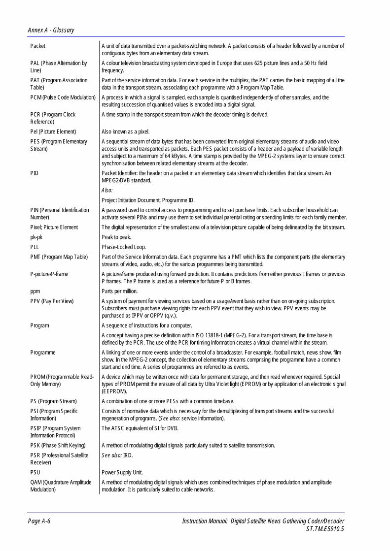
Annex A - Glossary
Page A-6 Instruction Manual: Digital Satellite News Gathering Coder/DecoderST.TM.E5910.5
Packet A unit of data transmitted over a packet-switching network. A packet consists of a header followed by a number ofcontiguous bytes from an elementary data stream.
PAL (Phase Alternation byLine)
A colour television broadcasting system developed in Europe that uses 625 picture lines and a 50 Hz fieldfrequency.
PAT (Program AssociationTable)
Part of the service information data. For each service in the multiplex, the PAT carries the basic mapping of all thedata in the transport stream, associating each programme with a Program Map Table.
PCM (Pulse Code Modulation) A process in which a signal is sampled, each sample is quantised independently of other samples, and theresulting succession of quantised values is encoded into a digital signal.
PCR (Program ClockReference)
A time stamp in the transport stream from which the decoder timing is derived.
Pel (Picture Element) Also known as a pixel.
PES (Program ElementaryStream)
A sequential stream of data bytes that has been converted from original elementary streams of audio and videoaccess units and transported as packets. Each PES packet consists of a header and a payload of variable lengthand subject to a maximum of 64 kBytes. A time stamp is provided by the MPEG-2 systems layer to ensure correctsynchronisation between related elementary streams at the decoder.
PID Packet Identifier: the header on a packet in an elementary data stream which identifies that data stream. AnMPEG2/DVB standard.
Also:
Project Initiation Document, Programme ID.
PIN (Personal IdentificationNumber)
A password used to control access to programming and to set purchase limits. Each subscriber household canactivate several PINs and may use them to set individual parental rating or spending limits for each family member.
Pixel; Picture Element The digital representation of the smallest area of a television picture capable of being delineated by the bit stream.
pk-pk Peak to peak.
PLL Phase-Locked Loop.
PMT (Program Map Table) Part of the Service Information data. Each programme has a PMT which lists the component parts (the elementarystreams of video, audio, etc.) for the various programmes being transmitted.
P-picture/P-frame A picture/frame produced using forward prediction. It contains predictions from either previous I frames or previousP frames. The P frame is used as a reference for future P or B frames.
ppm Parts per million.
PPV (Pay Per View) A system of payment for viewing services based on a usage/event basis rather than on on-going subscription.Subscribers must purchase viewing rights for each PPV event that they wish to view. PPV events may bepurchased as IPPV or OPPV (q.v.).
Program A sequence of instructions for a computer.
A concept having a precise definition within ISO 13818-1 (MPEG-2). For a transport stream, the time base isdefined by the PCR. The use of the PCR for timing information creates a virtual channel within the stream.
Programme A linking of one or more events under the control of a broadcaster. For example, football match, news show, filmshow. In the MPEG-2 concept, the collection of elementary streams comprising the programme have a commonstart and end time. A series of programmes are referred to as events.
PROM (Programmable Read-Only Memory)
A device which may be written once with data for permanent storage, and then read whenever required. Specialtypes of PROM permit the erasure of all data by Ultra Violet light (EPROM) or by application of an electronic signal(EEPROM).
PS (Program Stream) A combination of one or more PESs with a common timebase.
PSI (Program SpecificInformation)
Consists of normative data which is necessary for the demultiplexing of transport streams and the successfulregeneration of programs. (See also: service information).
PSIP (Program SystemInformation Protocol)
The ATSC equivalent of SI for DVB.
PSK (Phase Shift Keying) A method of modulating digital signals particularly suited to satellite transmission.
PSR (Professional SatelliteReceiver)
See also: IRD.
PSU Power Supply Unit.
QAM (Quadrature AmplitudeModulation)
A method of modulating digital signals which uses combined techniques of phase modulation and amplitudemodulation. It is particularly suited to cable networks.

Annex A - Glossary
Instruction Manual: Digital Satellite News Gathering Coder/Decoder Page A-7ST.TM.E5910.5
QPSK (Quadrature PhaseShift Keying)
A form of phase shift keying modulation using four states.
Quantising: Quantisation A process in which the continuous range of values that a quantity may assume is divided into a number ofpredetermined adjacent intervals and in which any value within a given interval is represented by a singlepredetermined value within the interval.
Also:
A restriction of the number of DCT coefficient values, resulting in a limiting of the luminance and chrominanceinformation.
RAM (Random AccessMemory)
A volatile storage device for digital data. Data may be written to, or read from, the device as often as required.When power is removed, the data it contains is lost.
RF Radio Frequency.
ROM (Read-Only Memory) A non-volatile storage device for digital data. Data has been stored permanently in this device. No furtherinformation may be stored (written) there and the data it holds cannot be erased. Data may be read as often asrequired.
RS (Reed Solomon coding) An error detection and correction coding system which is applied to the Transport Stream before transmission tocounter the effects of interference.
RLC (Run Length Coding) Minimisation of the length of a bit stream by replacing repeated characters with an instruction of the form ‘repeatcharacter x y times’.
SCPC Single Channel Per Carrier.
Scrambling Alteration of the characteristics of a television signal in order to prevent unauthorised reception of the information inclear form.
Also:
A process (in digital transmission) used to combine a digital signal with a pseudo-random sequence, producing arandomised digital signal, conveying the same information, in order to facilitate transmission.
SDT (Service DescriptionTable)
Provides information in the SI stream about the services in the system; for example, the name of the service, theservice provider, etc.
SELV Safety Extra Low Voltage (EN 60950).
Set-Top Box (STB) The cable equivalent of the IRD (q.v.)
SFN Single Frequency Network.
SI (Service Information) Digital data describing the delivery system, content and scheduling/timing of broadcast data streams. SI dataprovides information to enable the IRD to automatically demultiplex and decode the various streams ofprogrammes within the multiplex. Specified in ISO/IEC 13818[1].
Smart Card See: Viewing Card.
SMATV (Satellite MastAntenna Television)
A distribution system which provides sound and television signals to the households of a building or group ofbuildings, typically used to refer to an apartment block.
SMPTE Society of Motion Picture and Television Engineers.
SMS (Subscriber ManagementSystem)
A system which handles the maintenance, billing, control and general supervision of subscribers to conditionalaccess technology viewing services provided through cable and satellite broadcasting. The SMS system providedby NDS links a number of Users on a LAN with Batch Processors and a File Server providing access to aDatabase and a separate dedicated Conditional Access Interface Server which communicates with anAuthorisation Control Centre (ACC).
An SMS can be an automatic (e.g. Syntellect) system where subscribers order entitlements by entering informationvia a telephone. Alternatively, an SMS can be a manual system which requires subscribers to speak with anoperator who manually enters their entitlement requests. Some systems support multiple SMSs.
SNG Satellite News-Gathering.
SNMP Simple Network Management Protocol.
Spatial Redundancy Information repetition due to areas of similar luminance and/or chrominance characteristics within a single frame.Removed using DCT and Quantisation (Intra-Frame Coding).
SPI Synchronous Parallel Interface.
Statistical Redundancy Data tables are used to assign fewer bits to the most commonly occurring events, thereby reducing the overall bitrate. Removed using Run Length Coding and Variable Length Coding.
STB (Set-Top Box) See: IRD.

Annex A - Glossary
Page A-8 Instruction Manual: Digital Satellite News Gathering Coder/DecoderST.TM.E5910.5
TAXI (TransparentAsynchronous Tx/Rx Interface)
A proprietary multiplexer interface.
TCP/IP (Transmission ControlProtocol/Internet Protocol)
A set of communications protocols that may be used to connect different types of computers over networks.
TDM (Time Division Multiplex) One common, physical communications channel for a number of signals, each with its own allotted time slot.
TDT (Time and Date Table) Part of the Service Information. The TDT gives information relating to the present time and date.
Temporal Redundancy Information repetition due to areas of little or no movement between successive frames. Removed using motionestimation and compensation (Inter-Frame Coding).
Time Stamp A term that indicates the time of a specific action such as the arrival of a byte or the presentation of a presentationunit.
Transport Stream A set of packetised elementary data streams and SI streams which may comprise more than one programme, butwith common synchronisation and error protection.
The data structure is defined in ISO/IEC 13818-1 [1] and is the basis of the ETSI Digital Video Broadcastingstandards.
Transport Stream PacketHeader
A data structure used to convey information about the transport stream payload.
TS Transport stream. A combination of one or more fixed length PESs with independent timebases into a singlestream.
TSP Transport Stream Processor.
U 44.45 mm (rack height standard).
UART (UniversalAsynchronous ReceiverTransmitter)
Located in the ICAM, provides byte and packet level communication with the viewing card. Also preparesinformation for serial communication.
Upconvert/ Downconvert The process by which the frequency of a broadcast transport stream is shifted to a higher (lower) frequency range.
Uplink The part of the communications satellite circuit that extends from the Earth to the satellite.
UPS (Uninterruptable PowerSupply)
A device that conditions the power supply to equipment to ensure continuous power and the avoidance of powersurges. It also provides power from batteries, for a short time, in case of mains failure.
UTC Universal Time, Co-ordinated (previously Greenwich Mean Time or GMT).
Also
Unique Title Code.
VideoCrypt IVideoCrypt II
A brand name for NDS conditional access technology used by some analogue customers. Videocrypt was jointlydeveloped by Videocrypt and NDS (formerly News Datacom at the time), and produces the chipset. Known asThomson Multimedia in Europe. NDS later developed an independent system called NewsCrypt.
VideoGuard A brand name for News Datacom conditional access technology.
Viewing Card A credit-card sized programmable card. A CA security device in the subscriber’s home, it receives and recordsentitlements from the ACC and checks these against the incoming programme information in the ECMs. If thesubscriber is authorised by the SMS to view the current programme, the card provides the control word to the IRD.(Also known generally as a smart card or subscriber access card.)
VITS Vertical Interval Test Signal. See: ITS.
VPS Video Programming System.
WSS (Wide Screen Switching) Data used in wide-screen analogue services which enables a receiver to select the appropriate display mode.
WST World System Teletext.
XILINX A type of programmable Integrated Circuit.
Y (Luminance) Defines the brightness of a particular point on a TV line.

Instruction Manual: Digital Satellite News Gathering Coder/Decoder Page B-1ST.TM.E5910.5
Annex BB. Technical Specifications
ContentsB.1 Signal Interface ............................................................ B-3
Video Inputs........................................................ B-3Audio Inputs........................................................ B-4RS-422 Synchronous Data Input ........................ B-5RS-232 Asynchronous Data Inputs .................... B-5Transport Stream Output.................................... B-5IF Output (Main) ................................................. B-6IF Monitor Output 1............................................. B-7IF Monitor Output 2 (IRD) ................................... B-7IRD Inputs (M2/ESN/SNGB option only) ............ B-7IRD Outputs (M2/ESN/SNGB option only).......... B-8
B.2 Control and Monitoring Interface.................................. B-9Local Control ...................................................... B-9Remote Control RS-485 / RS-422 ...................... B-9Reset/Status ..................................................... B-10
B.3 Power Supply............................................................. B-10Power Requirements ........................................ B-10
B.4 Physical Details.......................................................... B-11
B.5 Environmental Conditions .......................................... B-12
B.6 Compliance................................................................ B-13Safety ............................................................... B-13EMC.................................................................. B-13
B.7 CE Marking ................................................................ B-13
B.8 C-Tick Mark................................................................ B-14
List of TablesTable B.1: Composite Video Input Specification............................B-3Table B.2: Component Video Input Specification ..........................B-3Table B.3: Digital Parallel Video Input Specification......................B-3Table B.4: Digital Serial Video Input Specification.........................B-4Table B.5: Video Compression Specification.................................B-4Table B.6: Audio Input Specification..............................................B-4Table B.7: RS-422 Synchronous Data Input Specification ............B-5Table B.8: RS-232 Asynchronous Data Input Specification...........B-5Table B.9: Transport Stream Output Specification ........................B-5Table B.10: IF Output (Main) Specification....................................B-6Table B.11: Signal-to-Noise Ratio and FEC Rate..........................B-6Table B.12: IF Monitor Output 1 Specification ...............................B-7Table B.13: IF Monitor Output 2 (IRD) Specification......................B-7Table B.14: IRD L-band Input Specification...................................B-7Table B.15: IRD IF Input Specification...........................................B-8Table B.16: IRD Transport Stream Input Specification ..................B-8Table B.17: IRD Composite Video Output Specification................B-8Table B.18: IRD Audio Output Specification..................................B-8Table B.19: RS-232 Asynchronous Data Output Specification......B-9Table B.20: RS-422 Synchronous Data Output Specification........B-9Table B.21: Remote Control (RS-485 / RS-422) Port
Specification .................................................................B-9Table B.22: Reset/Status Port Specification................................B-10Table B.23: Power Supply Specification......................................B-10Table B.24: Physical Details ........................................................B-11Table B.25: Environmental Specification .....................................B-12

Annex B - Technical Specifications
Page B-2 Instruction Manual: Digital Satellite News Gathering Coder/DecoderST.TM.E5910.5
BLANK

Annex B - Technical Specifications
Instruction Manual: Digital Satellite News Gathering Coder/Decoder Page B-3ST.TM.E5910.5
B.1 Signal InterfaceVideo Inputs
Composite (PAL or NTSC)
Table B.1: Composite Video Input Specification
Item Specification
Analogue input: 625 line composite PAL System B, G, H, I as specified in CCIR (ITU-R) report 624-4 “Characteristics of Television Systems” and“Standards for 625-Line System I Transmissions in the UnitedKingdom”, DTI 1984
or 525 line composite NTSC-M as specified in CCIR (ITU-R) report 624-4“Characteristics of Television Systems”
Connector designation: COMPOSITE/Y
Connector type: BNC female socket
Input impedance: 75 Ω
Input level: 1 V pk-pk nominal ±5%
Return loss: >30 dB up to 6 MHz
Analogue Component (YUV)
Table B.2: Component Video Input Specification
Item Specification
Input standard: Betacam Y, Pr, Pb, syncs on Y
Connector designation: COMPOSITE/Y, B-Y, R-Y
Connector type: Three BNC female sockets
Input impedance: 75 Ω
Input level: 1 V pk-pk nominal ±5%
Return loss: >30 dB up to 6 MHz
Digital Parallel
Table B.3: Digital Parallel Video Input Specification
Item Specification
Input standard (UK/EEC):
Input standard (USA):
CCIR Rec. 656-1 (ITU-R BT.656) 4:2:2 YCbCr (625/525 lines,selectable)
ANSI / SMPTE 125M -1992 “Television - Component Video Signal4:2:2 - Bit Parallel Digital Interface”
Input format: Digital parallel CCIR Rec. 656-1 part 2 (ITU-R BT.656)
Connector designation: PARALLEL
Connector type: 25-way D-type female
Input impedance: 110 Ω ±10 Ω
Input level: ECL-compatible, 2 V pk-pk max.
Int. Test Pattern Generator: All ITU-R BT. 656 codes

Annex B - Technical Specifications
Page B-4 Instruction Manual: Digital Satellite News Gathering Coder/DecoderST.TM.E5910.5
Digital Serial
Table B.4: Digital Serial Video Input Specification
Item Specification
Input standard (UK/EEC):
Input standard (USA)
CCIR Rec. 656-1 (ITU-R BT.656) 4:2:2 YCbCr
ANSI / SMPTE 259M -1993 “Television - 10-bit 4:2:2 - Component and4fsc NTSC Composite Digital Signals - Serial Digital Interface”
Input format: Digital serial CCIR Rec. 656-1 part 3 (ITU-R BT.656)
Connector designation: SERIAL
Connector type: BNC female socket
Input impedance: 75 Ω
Cable length: 125 m, maximum
Input level: 800 mV pk-pk nominal ±10%
Return loss: >15 dB, 10-270 MHz
Video Compression
Table B.5: Video Compression Specification
Item Specification
Resolution (625 line mode): 704 pixels x 576 lines544 pixels x 576 lines480 pixels x 576 lines352 pixels x 576 lines352pixels x 288 lines (SIF)
Resolution (525 line mode): 704 pixels x 480 lines544 pixels x 480 lines480 pixels x 480 lines352 pixels x 480 lines352 pixels x 240 lines (SIF)
Bit-rate: 1.5 - 5 Mbit/s (selectable) - SIF2 - 15 Mbit/s (selectable) - all other resolutions
Compression standard: MPEG-2, Main Profile, Main Level
Audio InputsTable B.6: Audio Input Specification
Item Specification
Input standard (analogue): Balanced analogue
Input level: 0, +3, +6, +9, +12 or 18 dBm (factory set). +12 dBm = default
Input impedance: 600 Ω or 20 kΩ (selectable)
Input standard (digital): AES/EBU digital (selectable)
Sampling rate: 48 kHz
Connector designation: L/DIGITAL, R
Connector type: XLR female socket (left socket is digital I/P)
Coding algorithm: MPEG-1 / MPEG-2 Layer 1 / Layer 2
Supported coding modes: Single channel, dual channel, joint stereo and normal stereo
Supported coded data rate: 32-384 kbit/s (layer 2), 32-448 kbit/s (layer 1) depending on.
selected mode - see Chapter 1, Introduction for details

Annex B - Technical Specifications
Instruction Manual: Digital Satellite News Gathering Coder/Decoder Page B-5ST.TM.E5910.5
RS-422 Synchronous Data Input
Table B.7: RS-422 Synchronous Data Input Specification
Item Specification
Type: ITU-T V.11 (RS-422), synchronous serial data and clock
Connector designation: RS-422
Connector type: 15-way D-type female
Clock frequencies: n x 64 kbit/s from 64 kbit/s to 1024 kbit/s (selectable)
Timestamp: Not supported
Operational modes: Bit-pipe - Transport packet and byte alignment relative to the incomingbit-stream are arbitrary.
RS-232 Asynchronous Data Inputs
Table B.8: RS-232 Asynchronous Data Input Specification
Item Specification
Type: ITU-T V.24/V.28 (RS-232D) asynchronous serial data
Connector designation: RS-232 CH A, RS-232 CH B
Connector type: 9-way D-type female
Supported baud rates: 1200, 2400, 4800, 9600 baud
Control mechanism: XON/XOFF
Timestamp: Not supported
Transport package alignment: Transparent to data source. Port operates as a bit-pipe
Transport Stream Output
Table B.9: Transport Stream Output Specification
Item Specification
Format: Parallel LVDS, as defined in the DVB Physical Interface Rec.
Connector designation: TRANSPORT STREAM OUTPUT DVB PARALLEL
Connector type: 25-way D-type female
Output data rate: 2-32 Mbit/s
Output data format: DVB compliant

Annex B - Technical Specifications
Page B-6 Instruction Manual: Digital Satellite News Gathering Coder/DecoderST.TM.E5910.5
IF Output (Main)
Table B.10: IF Output (Main) Specification
Item Specification
Connector type: BNC female socket
Connector designation: IF OUTPUT
Output Impedance: 75Ω
Output Power: -27 dBm to +5 dBm in 0.1 dB steps
Return loss: 20 dBm min.
Symbol rate: 1.5-16 MSymbol/s
Convolutional FEC rates: 1/2, 2/3, 3/4, 5/6 and 7/8.
Pulse-shaping filter: Nominally square root 35% cosine roll-off
Modulation: QPSK (as per ETS 300 421)
IF spectrum inversion: Selectable on/off
Transmission modes: Modulation on/offCarrier on/off
Carrier frequency: 70 MHz ± 20 MHz140 MHz ± 40 MHzTuneable in 125 kHz steps
Carrier frequency error: < 5 kHz
Carrier ON/OFF ratio: > 50 dB min.60 dB typical at +5 dBm output power
Carrier suppression (QPSKmode):
> 40 dB
Modulator implementation margin is compliant with ETS 300 421, testedwith NDS MPEG-2 Professional IRD. Receive Eb/N0 ratios (referred to thepacket bit-rate Rr) for BER = 2 x 10⁻⁴ at Viterbi Decoder output, Quasi ErrorFree at RS Decoder output are summarised below:
Table B.11: Signal-to-Noise Ratio and FEC Rate
ConvolutionalFEC rate
Eb/N0 ratio
1/2 4.5
2/3 5.0
3/4 5.5
5/6 6.0
7/8 6.4

Annex B - Technical Specifications
Instruction Manual: Digital Satellite News Gathering Coder/Decoder Page B-7ST.TM.E5910.5
IF Monitor Output 1
Table B.12: IF Monitor Output 1 Specification
Item Specification
Format: 70 / 140 MHz QPSK modulated output (tuneable)
Connector type: BNC female socket
Connector designation: IF MONITOR OUTPUT 1
Output power: -10 dB nominal, ±1 dB dependent on IF output power level
Output Impedance: 75 Ω
Return loss: 15 dBm min.
IF Monitor Output 2 (IRD)
Table B.13: IF Monitor Output 2 (IRD) Specification
Item Specification
Format: 70 / 140 MHz QPSK modulated output (tuneable)
Connector type: BNC female socket
Connector designation: IF MONITOR OUTPUT 2 (IRD)
Output power: -10 dB nominal, ±1 dB dependent on IF output power level
Output Impedance: 75 Ω
Return loss: 15 dBm min.
IRD Inputs (M2/ESN/SNGB option only)
L-Band
Table B.14: IRD L-band Input Specification
Item Specification
Connector type: BNC female socket
Connector designation: L-BAND
Input Impedance: 75 Ω
Input power: -30 to -65 dBm
Input frequency: 950 to 2050 MHz
Tuning increment: 125 kHz
IF filter bandwidth: 27 MHz/36 MHz (automatic selection dependent on symbol rate)
LNB control: Receive polarisation control by electrical command via LNB IF feeder(normal and inverse spectrum)
Control voltage: 11.5 to 14 V (polarisation 1), 16 to 19 V (polarisation 2) as ETS 300249 and ETS 300 158
Signal format: As per ETS 300421
Symbol rate: 1.5 to 30 Msym/s

Annex B - Technical Specifications
Page B-8 Instruction Manual: Digital Satellite News Gathering Coder/DecoderST.TM.E5910.5
70 / 140 MHz IF
Table B.15: IRD IF Input Specification
Item Specification
Connector type: BNC female socket
Connector designation: IF
Input power: -10 dBm
Input Impedance: 75 Ω
Input frequency: 70 MHz ±20 MHz
140 MHz ±40 MHz
Tuning increment: 125 kHz
Transport Stream
Table B.16: IRD Transport Stream Input Specification
Item Specification
Format: Parallel LVDS as defined in the DVB Physical Interface Rec.
Connector type: 25-way D-type female socket
Connector designation: TRANSPORT STREAM INPUT DVB PARALLEL
IRD Outputs (M2/ESN/SNGB option only)
Composite Video
Two composite video outputs provide the same video signal.
Table B.17: IRD Composite Video Output Specification
Item Specification
Connector type: BNC female socket
Connector designation: COMPOSITE VIDEO OUTPUTS CH A, CH B
Video standards: PAL-B, -D*, -G, -H, -I, -MNTSC-M
* = some fine detail may be filtered out.
Load Impedance: 75 Ω
Output level: 1 V pk-pk
Audio
Two analogue channels are useable for stereo or two mono outputs.
Table B.18: IRD Audio Output Specification
Item Specification
Connector type: XLR male socket
Connector designation: AUDIO OUTPUTS R, L
Load Impedance: 600 Ω
Output level: +9, +12, +15, +18 dBm

Annex B - Technical Specifications
Instruction Manual: Digital Satellite News Gathering Coder/Decoder Page B-9ST.TM.E5910.5
RS-232 Data
Table B.19: RS-232 Asynchronous Data Output Specification
Item Specification
Type: CCITT V.24/V.28 (RS-232D) asynchronous serial data
Connector designation: DATA OUTPUT RS-232
Connector type: 9-way D-type female
Supported baud rates: 1200, 2400, 4800, 9600 baud
Transport package alignment: XON/XOFF
RS-422 Data
Table B.20: RS-422 Synchronous Data Output Specification
Item Specification
Type: CCITT V.11 (RS-422), synchronous serial data and external clock
Connector designation: DATA OUTPUT RS-422
Connector type: 15-way D-type male
Clock frequencies: n x 64 kbit/s from 64 kbit/s to 1024 kbit/s
B.2 Control and Monitoring Interface
Local ControlLocal control and operation of the unit is effected by a front panelmembrane keypad and associated 20 character by 4 line Vacuum fluorescentdisplay. These are used to display, select and change parameters which arearranged on a series of display menus (for details see Chapter 3, LocalControl and Operation).
Remote Control RS-485 / RS-422An RS-485 / RS-422 interface is provided for the connection of a remotecontrol terminal. This may be used to control the system configuration andoperation (for details see DSNG Codec Remote Control InterfaceSpecification ST.TS.E5910).
Table B.21: Remote Control (RS-485 / RS-422) Port Specification
Item Specification
Connector designation: CONTROL MULTIDROP RS-485/RS-422
Connector type: 9-way D-type female
Baud rate: Selectable - 1200, 2400, 4800, 9600 or 19200 baud
Protocol: Selectable - 7/8 data bits, 1/2 stop bits, no parity
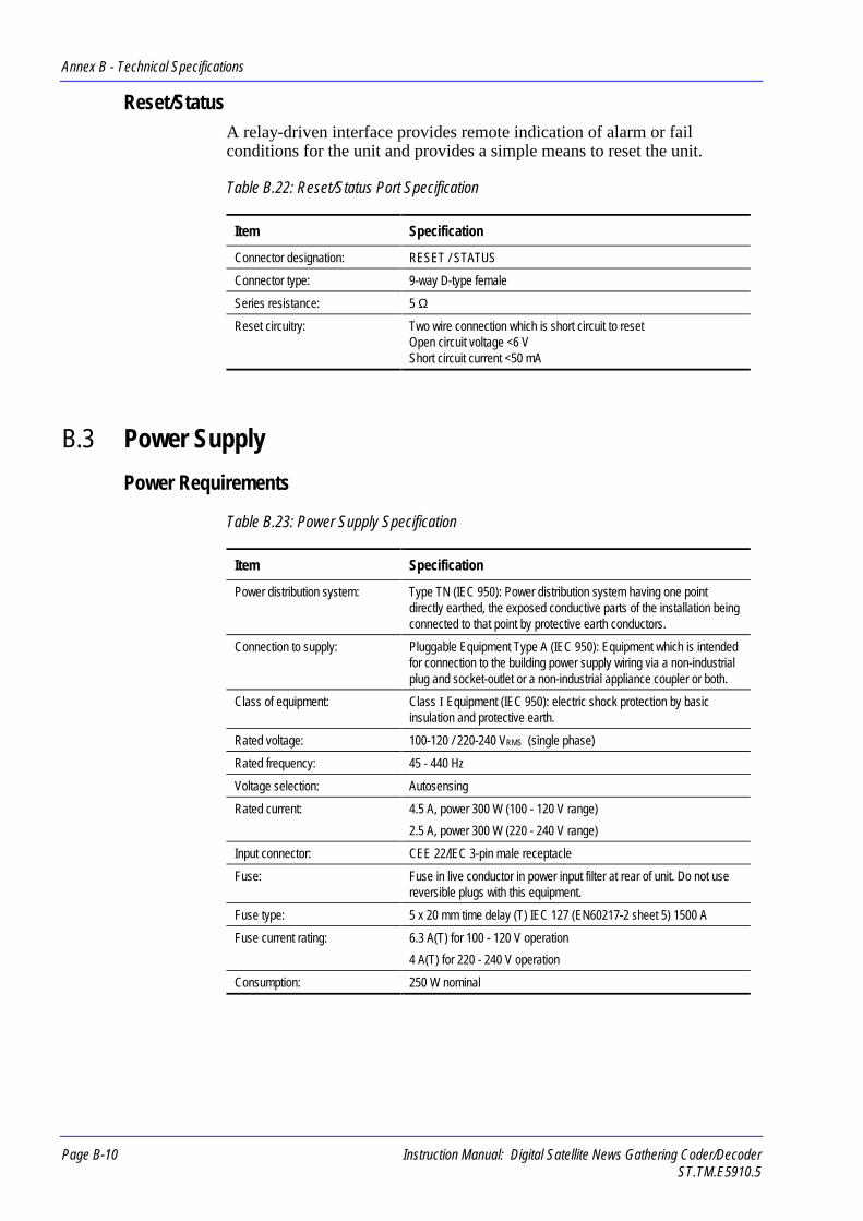
Annex B - Technical Specifications
Page B-10 Instruction Manual: Digital Satellite News Gathering Coder/DecoderST.TM.E5910.5
Reset/StatusA relay-driven interface provides remote indication of alarm or failconditions for the unit and provides a simple means to reset the unit.
Table B.22: Reset/Status Port Specification
Item Specification
Connector designation: RESET / STATUS
Connector type: 9-way D-type female
Series resistance: 5 Ω
Reset circuitry: Two wire connection which is short circuit to resetOpen circuit voltage <6 VShort circuit current <50 mA
B.3 Power Supply
Power Requirements
Table B.23: Power Supply Specification
Item Specification
Power distribution system: Type TN (IEC 950): Power distribution system having one pointdirectly earthed, the exposed conductive parts of the installation beingconnected to that point by protective earth conductors.
Connection to supply: Pluggable Equipment Type A (IEC 950): Equipment which is intendedfor connection to the building power supply wiring via a non-industrialplug and socket-outlet or a non-industrial appliance coupler or both.
Class of equipment: Class I Equipment (IEC 950): electric shock protection by basicinsulation and protective earth.
Rated voltage: 100-120 / 220-240 VRMS (single phase)
Rated frequency: 45 - 440 Hz
Voltage selection: Autosensing
Rated current: 4.5 A, power 300 W (100 - 120 V range)
2.5 A, power 300 W (220 - 240 V range)
Input connector: CEE 22/IEC 3-pin male receptacle
Fuse: Fuse in live conductor in power input filter at rear of unit. Do not usereversible plugs with this equipment.
Fuse type: 5 x 20 mm time delay (T) IEC 127 (EN60217-2 sheet 5) 1500 A
Fuse current rating: 6.3 A(T) for 100 - 120 V operation
4 A(T) for 220 - 240 V operation
Consumption: 250 W nominal

Annex B - Technical Specifications
Instruction Manual: Digital Satellite News Gathering Coder/Decoder Page B-11ST.TM.E5910.5
B.4 Physical DetailsTable B.24: Physical Details
Item Specification
Height: 222 mm (8.75”), 5U chassis
Width: 435 mm (17.13”) excluding fixing brackets
Overall width: 482 mm (19”) including fixing brackets
Depth: 470 mm (18.5”) excluding rear connector clearance
Mounting holes: 465 mm (18.3”) horizontal
Ventilation: 6 PAPST fans located in the right-hand side of the unit
Air flow: Intake on LHS. Exhaust on RHS.
Approximate weight: 23 kg (50.7 lb.)

Annex B - Technical Specifications
Page B-12 Instruction Manual: Digital Satellite News Gathering Coder/DecoderST.TM.E5910.5
B.5 Environmental ConditionsTable B.25: Environmental Specification
Item Specification
Operational
Temperature: -20°C to +50°C ambient with free air flow
NOTE…The operation of this unit to specification can not be guaranteed below0°C due to the commercial specification of the semiconductors used.However, extensive tests show that in practice the unit will operatereliably under these conditions.
Humidity: 0% to 90% (non-condensing)
Cooling requirements: Free air flow for 50 mm around the sides of the unit
Handling/movement: Designed for fixed use when in operation
Warm-up: Unit may require up to 10 minutes warm-up time when operating at -20°C
Waterproofing: Front Panel is splashproof
Storage/ Transportation
Temperature: -20°C to +70°C
Handling/movement: Designed for truck or flyaway transportation (when mounted in asuitable flight case)
Humidity: 0% to 90% (non-condensing)
Transportation Survivability (when properly mounted in a suitable flight case)
Free fall: BS EN 60068-2-32:Part 2 Test Ed:1993
Height of fall: 0.5m
Test surface: concrete
Number of falls: 2 per face
Vibration (sinusoidal): BS 2011:Part 2.1 Fc:1983
Frequency range: 5-8.5 Hz, amplitude 3.5 mm
Frequency range: 8.5-350 Hz, amplitude 1.0g
Sweep rate: 1 octave/minute
Duration: 20 cycles in each mutual perpendicular axis
Vibration (random): BS 2011:Part 2.1 Fdb:1973 with Amendments No. 1 (1977) and No. 2(1984)
Frequency range: 20-20000 Hz
ASD level: 0.048 m2/s3
Duration: 2 hours in each mutually perpendicular axis
Bump: BS 2011:Part 2.1 Eb:1987 with Amendment No. 1 (1993)
Pulse shape: half-sine
Pulse duration: 6 ms
Amplitude: 25 g
Number of bumps: 500 per direction
Please contact Customer Support at the address given at the front of thismanual for recommendations regarding flight case suitability.

Annex B - Technical Specifications
Instruction Manual: Digital Satellite News Gathering Coder/Decoder Page B-13ST.TM.E5910.5
B.6 Compliance1
SafetyThis equipment has been designed and tested to meet the following:
EN 60950:1992
European Safety of information technologyequipment including business equipment(including amendment 2).
IEC950:1992
International Safety of information technologyequipment including business equipment(including amendment 2).
EMC2
This equipment has been designed and tested to meet the following:
EN55022:Aug 1994AS/NZS 3548
European
Australian/New Zealand
Emission StandardLimits and methods of Measurement ofRadio Frequency InterferenceCharacteristics of InformationTechnology Equipment – Class B.
EN50082-1:Jan 1992
European Generic Immunity StandardPart 1: Residential, commercial and lightindustry.
FCC USA Conducted and radiated emission limitsfor a Class A digital device, pursuant tothe Code of Federal Regulations (CFR)Title 47-Telecommunications, Part 15Radio frequency devices, subpart B -Unintentional Radiators, Section 15.10715.109. (FCC Part 15 Class B forcomputer devices)
B.7 CE MarkingThe CE mark is affixed to indicate compliance with the followingdirectives:
89/336/EEC of 3 May 1989 on the approximation of the laws of theMember States relating to electromagnetic compatibility.
73/23/EEC of 19 February 1973 on the harmonisation of the laws of theMember States relating to electrical equipment designed for use withincertain voltage limits.
NOTE...
The CE mark was first affixed to this product in 1996.
1 The version of the standards shown is that applicable at the time of manufacture.2 The EMC tests were performed with the Technical earth attached, and configured using recommended
cables.

Annex B - Technical Specifications
Page B-14 Instruction Manual: Digital Satellite News Gathering Coder/DecoderST.TM.E5910.5
B.8 C-Tick Mark3
The C-Tick mark is affixed to denote compliance with the Australian“Radiocommunications (Compliance and Labelling – IncidentalEmissions) Notice made under s.182 of Radiocommunications Act 1992.
3 All units comply with the C-Tick Mark but only those manufactured after March 1999 carry the label.

Instruction Manual: Digital Satellite News Gathering Coder/Decoder Page C-1ST.TM.E5910.5
Annex CC. Default Configurations
ContentsC.1 Using / Restoring Default Configurations ....................C-3
C.2 Default Configuration 0 (Current) ................................C-3
C.3 Default Configuration 1................................................C-5
C.4 Default Configuration 2................................................C-5
C.5 Default Configuration 3................................................C-6
C.6 Default Configuration 4................................................C-6
C.7 Default Configuration 5................................................C-6
C.8 Default Configuration 6................................................C-7
C.9 Default Configuration 7................................................C-7
C.10 Default Configuration 8..............................................C-8
C.11 Default Configuration 9..............................................C-8
C.12 Default Configuration 10............................................C-9
C.13 Default Configuration 11............................................C-9
C.14 Default Configuration 12............................................C-9
C.15 Default Configuration 13..........................................C-10
C.16 Default Configuration 14..........................................C-10
C.17 Default Configuration 15..........................................C-11
C.18 Default Configuration 16..........................................C-11
List of TablesTable C.1: Default Configuration 0 (Current) ................................ C-3Table C.2: Default Configuration 1................................................ C-5Table C.3: Default Configuration 3................................................ C-6Table C.4: Default Configuration 4................................................ C-6Table C.5: Default Configuration 5................................................ C-6Table C.6: Default Configuration 6................................................ C-7Table C.7: Default Configuration 7................................................ C-7Table C.8: Default Configuration 8................................................ C-8Table C.9: Default Configuration 9................................................ C-8Table C.10: Default Configuration 10............................................ C-9Table C.11: Default Configuration 11............................................ C-9Table C.12: Default Configuration 12............................................ C-9Table C.13: Default Configuration 13.......................................... C-10Table C.14: Default Configuration 14.......................................... C-10Table C.15: Default Configuration 15.......................................... C-11Table C.16: Default Configuration 16.......................................... C-11

Annex C - Default Configurations
Page C-2 Instruction Manual: Digital Satellite News Gathering Coder/DecoderST.TM.E5910.5
BLANK

Annex C - Default Configurations
Instruction Manual: Digital Satellite News Gathering Coder/Decoder Page C-3ST.TM.E5910.5
C.1 Using / Restoring Default ConfigurationsThe DSNG Codec is supplied with 16 default configurations which havebeen set up to suit a wide variety of applications. These configurations areundeleteable and may be restored to the current / editable configurations byusing the Setup / Restore Orig Confgs option.
NOTE…
Restoring the default configuration files will erase all 16 of the current editable files andthe current configuration being used. In order to preserve these customer specificconfigurations use the Setup / Backup Configs option.
The default configuration parameter values and settings are listed here toenable you to see what you are getting before carrying out a Restorecommand.
C.2 Default Configuration 0 (Current)Configuration 0 is the configuration currently in use.
Table C.1: Default Configuration 0 (Current)
Function Parameter Value / Setting
System Service Name 9 MHz, PAL, 2 Audio
Config Title 9 MHz/PAL 2
Setup/Diagnostics Mode Enbaled
Local/Remote Control Local
Remote Control Address 49
Remote Control Baud Rate 19200
Remote Control Parity None
Remote Ctrl No. of Data Bits 8
Remote Ctrl No. of Stop Bits 1
Display Brightness 50%
Modulator Tx Bandwidth 9 MHz
Symbol Rate 7.031 MSym/s
FEC Rate 3/4
Spectrum Inversion Off
Modulation Off
IF Output Off
IF Frequency 70 MHz
IF Preset Output Power -15 dBm
Multiplexer Output Format IF output
Bit-rate 18 Mbit/s
RS Code On
Scrambling Off
Scrambling Code 0000000
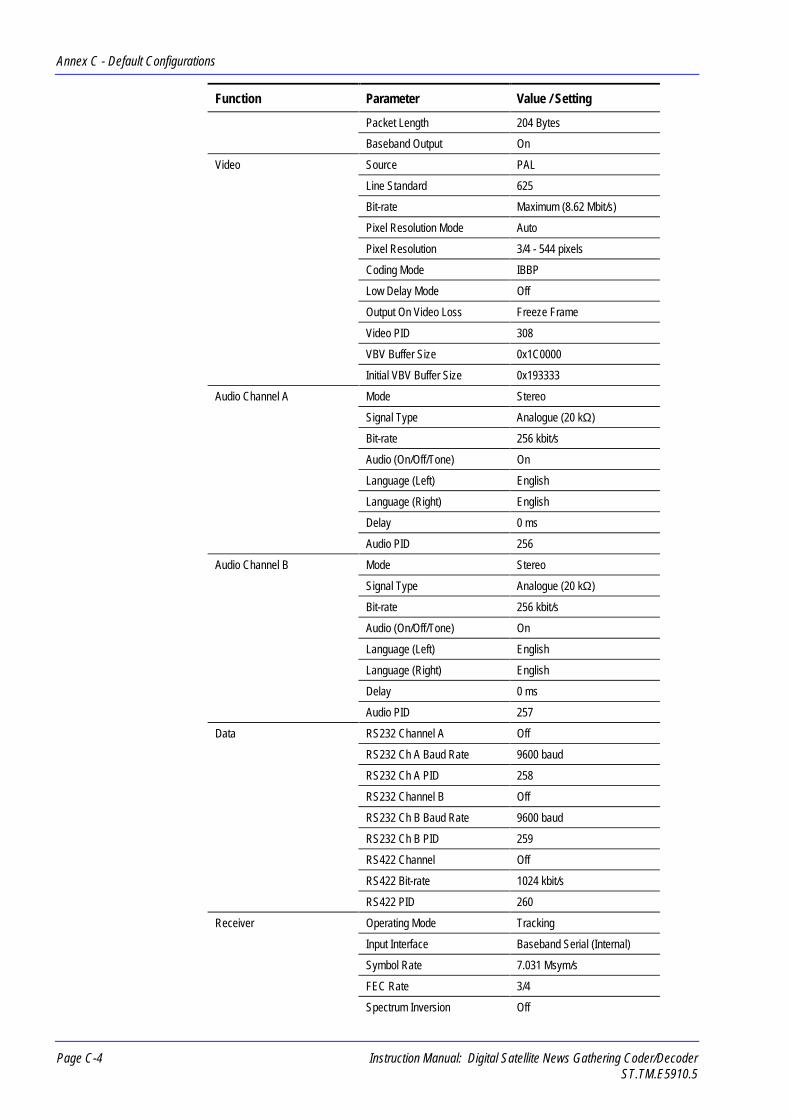
Annex C - Default Configurations
Page C-4 Instruction Manual: Digital Satellite News Gathering Coder/DecoderST.TM.E5910.5
Function Parameter Value / Setting
Packet Length 204 Bytes
Baseband Output On
Video Source PAL
Line Standard 625
Bit-rate Maximum (8.62 Mbit/s)
Pixel Resolution Mode Auto
Pixel Resolution 3/4 - 544 pixels
Coding Mode IBBP
Low Delay Mode Off
Output On Video Loss Freeze Frame
Video PID 308
VBV Buffer Size 0x1C0000
Initial VBV Buffer Size 0x193333
Audio Channel A Mode Stereo
Signal Type Analogue (20 kΩ)
Bit-rate 256 kbit/s
Audio (On/Off/Tone) On
Language (Left) English
Language (Right) English
Delay 0 ms
Audio PID 256
Audio Channel B Mode Stereo
Signal Type Analogue (20 kΩ)
Bit-rate 256 kbit/s
Audio (On/Off/Tone) On
Language (Left) English
Language (Right) English
Delay 0 ms
Audio PID 257
Data RS232 Channel A Off
RS232 Ch A Baud Rate 9600 baud
RS232 Ch A PID 258
RS232 Channel B Off
RS232 Ch B Baud Rate 9600 baud
RS232 Ch B PID 259
RS422 Channel Off
RS422 Bit-rate 1024 kbit/s
RS422 PID 260
Receiver Operating Mode Tracking
Input Interface Baseband Serial (Internal)
Symbol Rate 7.031 Msym/s
FEC Rate 3/4
Spectrum Inversion Off

Annex C - Default Configurations
Instruction Manual: Digital Satellite News Gathering Coder/Decoder Page C-5ST.TM.E5910.5
Function Parameter Value / Setting
Polarisation (L-band) Off
LNB Power (L-band only) Off
LNB Local Oscillator Freq (L-band only)
10 GHz
Carrier Frequency (L-band &70 MHz only)
11.07 GHz
Scramble (On/Off) Off
Scramble Code 0000000
Video Stream PID 308
Audio Stream PID 256
RS232 Stream PID 258
PCR Stream PID 8190
BER Threshold 1e-4
Signal Threshold 130
525 Line Standard NTSC
625 Line Standard PAL
Output on Video Loss Freeze Frame
No. Sync on Video Loss 0 (syncs maintained forever)
On-Screen Display on SignalLoss
On
Audio Routing Stereo, L to left, R to right
Audio Gain +12 dBm
C.3 Default Configuration 1As configuration 0 except for:
Table C.2: Default Configuration 1
Function Parameter Value / Setting
System Service Name 9 MHz, PAL, 1 Audio
Config Title 9 MHz/PAL 1
Video Bit-rate Maximum (8.82 Mbit/s)
Audio Channel B Audio (On/Off/Tone) Test Tone
C.4 Default Configuration 2As configuration 0

Annex C - Default Configurations
Page C-6 Instruction Manual: Digital Satellite News Gathering Coder/DecoderST.TM.E5910.5
C.5 Default Configuration 3As configuration 0 except for:
Table C.3: Default Configuration 3
Function Parameter Value / Setting
System Service Name 9 MHz, PAL, 1 RS232
Config Title 9 MHz/PAL 3
Video Bit-rate Maximum (8.81 Mbit/s)
Audio Channel B Audio (On/Off/Tone) Test Tone
Data RS232 Ch A On
RS232 Ch A Baud Rate 9600 baud
C.6 Default Configuration 4As configuration 0 except for:
Table C.4: Default Configuration 4
Function Parameter Value / Setting
System Service Name 9 MHz, PAL, RS422
Config Title 9 MHz/PAL 4
Video Bit-rate Maximum (7.79 Mbit/s)
Audio Channel B Audio (On/Off/Tone) Test Tone
Data RS422 Channel On
RS422 Bit-rate 1024 kbit/s
C.7 Default Configuration 5As configuration 0 except for:
Table C.5: Default Configuration 5
Function Parameter Value / Setting
System Service Name 9 MHz, PAL, Interview
Config Title 9 MHz/PAL Int
Video Bit-rate Maximum (8.82 Mbit/s)
Low Delay Mode Manual Resolution
Audio Channel B Signal Test Tone

Annex C - Default Configurations
Instruction Manual: Digital Satellite News Gathering Coder/Decoder Page C-7ST.TM.E5910.5
C.8 Default Configuration 6As configuration 0 except for:
Table C.6: Default Configuration 6
Function Parameter Value / Setting
System Service Name 13.5 MHz, PAL, 2 Aud
Config Title 13.5 MHz/PAL
Modulator Tx Bandwidth 13.5 MHz
Symbol Rate 10.547 MSym/s
Video Bit-rate Maximum (13.37 Mbit/s)
Data RS232 Ch A On
RS232 Ch A Baud Rate 9600 baud
C.9 Default Configuration 7As configuration 0 except for:
Table C.7: Default Configuration 7
Function Parameter Value / Setting
System Service Name 18 MHz, PAL, Aud/Data
Config Title 18 MHz/PAL
Modulator Tx Bandwidth 18 MHz
Symbol Rate 14.063 MSym/s
Video Bit-rate Maximum (15.00 Mbit/s)
Data RS232 Ch A On
RS232 Ch A Baud Rate 9600 baud
RS232 Ch B On
RS232 Ch B Baud Rate 9600 baud
RS422 Ch B On
RS422 Bit-rate 1024 kbit/s

Annex C - Default Configurations
Page C-8 Instruction Manual: Digital Satellite News Gathering Coder/DecoderST.TM.E5910.5
C.10 Default Configuration 8As configuration 0 except for:
Table C.8: Default Configuration 8
Function Parameter Value / Setting
System Service Name 18 MHz, PAL, Aud/Data
Config Title Baseband/PAL
Modulator Tx Bandwidth 18 MHz
Symbol Rate 14.063 Msym/s
Multiplexer Output Format IF output
Bit-rate 18 Mbit/s
RS Code On
Packet Length 204 Bytes
Baseband Output On
Video Bit-rate Maximum (14.30 Mbit/s)
Data RS232 Ch A On
RS232 Ch A Baud Rate 9600 baud
RS232 Ch B On
RS232 Ch B Baud Rate 9600 baud
RS422 Channel On
RS422 Bit-rate 1024 kbit/s
C.11 Default Configuration 9As configuration 0 except for:
Table C.9: Default Configuration 9
Function Parameter Value / Setting
System Service Name 9 MHz, NTSC, 1 Audio
Config Title 9 MHz/NTSC 1
Video Video Source NTSC
Bit-rate Maximum (8.82 Mbit/s)
Audio Channel B Audio (On/Off/Test Tone) Test Tone
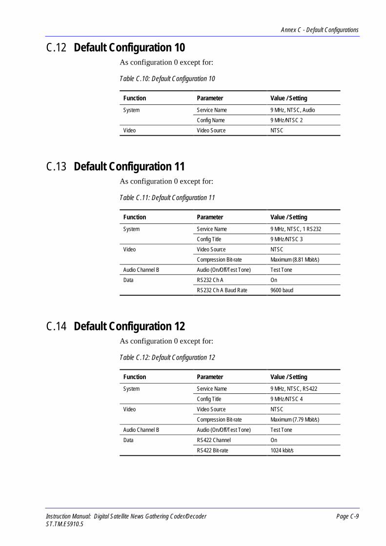
Annex C - Default Configurations
Instruction Manual: Digital Satellite News Gathering Coder/Decoder Page C-9ST.TM.E5910.5
C.12 Default Configuration 10As configuration 0 except for:
Table C.10: Default Configuration 10
Function Parameter Value / Setting
System Service Name 9 MHz, NTSC, Audio
Config Name 9 MHz/NTSC 2
Video Video Source NTSC
C.13 Default Configuration 11As configuration 0 except for:
Table C.11: Default Configuration 11
Function Parameter Value / Setting
System Service Name 9 MHz, NTSC, 1 RS232
Config Title 9 MHz/NTSC 3
Video Video Source NTSC
Compression Bit-rate Maximum (8.81 Mbit/s)
Audio Channel B Audio (On/Off/Test Tone) Test Tone
Data RS232 Ch A On
RS232 Ch A Baud Rate 9600 baud
C.14 Default Configuration 12As configuration 0 except for:
Table C.12: Default Configuration 12
Function Parameter Value / Setting
System Service Name 9 MHz, NTSC, RS422
Config Title 9 MHz/NTSC 4
Video Video Source NTSC
Compression Bit-rate Maximum (7.79 Mbit/s)
Audio Channel B Audio (On/Off/Test Tone) Test Tone
Data RS422 Channel On
RS422 Bit-rate 1024 kbit/s
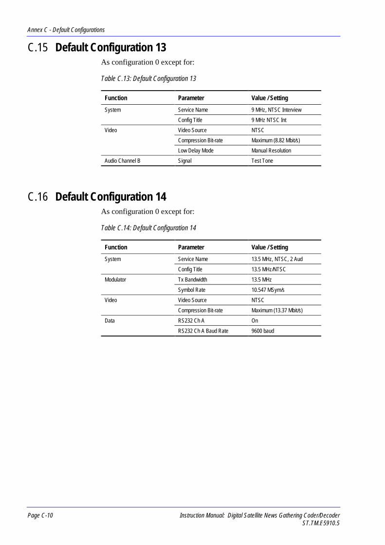
Annex C - Default Configurations
Page C-10 Instruction Manual: Digital Satellite News Gathering Coder/DecoderST.TM.E5910.5
C.15 Default Configuration 13As configuration 0 except for:
Table C.13: Default Configuration 13
Function Parameter Value / Setting
System Service Name 9 MHz, NTSC Interview
Config Title 9 MHz NTSC Int
Video Video Source NTSC
Compression Bit-rate Maximum (8.82 Mbit/s)
Low Delay Mode Manual Resolution
Audio Channel B Signal Test Tone
C.16 Default Configuration 14As configuration 0 except for:
Table C.14: Default Configuration 14
Function Parameter Value / Setting
System Service Name 13.5 MHz, NTSC, 2 Aud
Config Title 13.5 MHz/NTSC
Modulator Tx Bandwidth 13.5 MHz
Symbol Rate 10.547 MSym/s
Video Video Source NTSC
Compression Bit-rate Maximum (13.37 Mbit/s)
Data RS232 Ch A On
RS232 Ch A Baud Rate 9600 baud

Annex C - Default Configurations
Instruction Manual: Digital Satellite News Gathering Coder/Decoder Page C-11ST.TM.E5910.5
C.17 Default Configuration 15As configuration 0 except for:
Table C.15: Default Configuration 15
Function Parameter Value / Setting
System Service Name 18 MHz, NTSC Aud/Data
Config Title 18 MHz/NTSC
Modulator Tx Bandwidth 18 MHz
Symbol Rate 14.063 MSym/s
Video Video Source NTSC
Compression Bit-rate Maximum (15.00 Mbit/s)
Data RS232 Ch A On
RS232 Ch A Baud Rate 9600 baud
RS232 Ch B On
RS232 Ch B Baud Rate 9600 baud
RS422 Ch On
RS422 Bit-rate 1024 kbit/s
C.18 Default Configuration 16As configuration 0 except for:
Table C.16: Default Configuration 16
Function Parameter Value / Setting
System Service Name Bsbnd, NTSC Aud/Data
Config Title Bsband/NTSC
Modulator Tx Bandwidth 18 MHz
Symbol Rate 14.063 Msym/s
Multiplexer Output Format IF format
Bit-rate 18 Mbit/s
RS Code On
Packet Length 204 Bytes
Baseband Output On
Video Video Source NTSC
Compression Bit-rate Maximum (14.30 Mbit/s)
Data RS232 Ch A On
RS232 Ch A Baud Rate 9600 baud
RS232 Ch B On
RS232 Ch B Baud Rate 9600 baud
RS422 Ch On
RS422 Bit-rate 1024 kbit/s

Annex C - Default Configurations
Page C-12 Instruction Manual: Digital Satellite News Gathering Coder/DecoderST.TM.E5910.5
BLANK
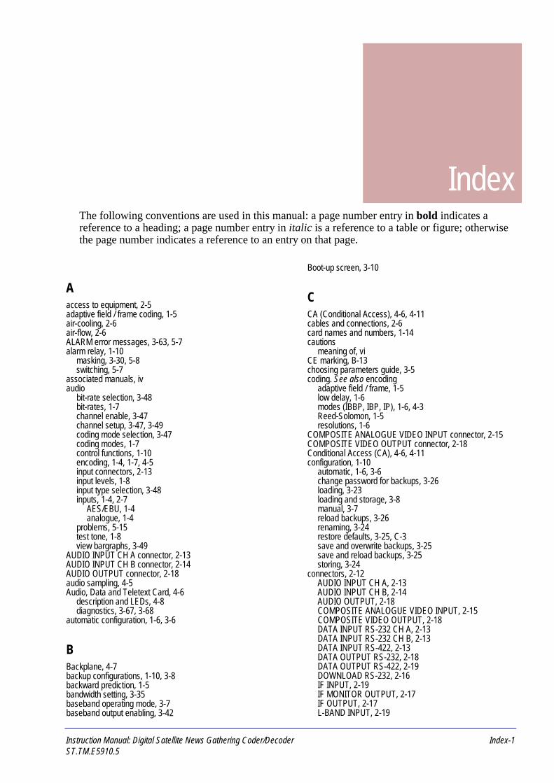
Instruction Manual: Digital Satellite News Gathering Coder/Decoder Index-1ST.TM.E5910.5
IndexThe following conventions are used in this manual: a page number entry in bold indicates areference to a heading; a page number entry in italic is a reference to a table or figure; otherwisethe page number indicates a reference to an entry on that page.
Aaccess to equipment, 2-5adaptive field / frame coding, 1-5air-cooling, 2-6air-flow, 2-6ALARM error messages, 3-63, 5-7alarm relay, 1-10
masking, 3-30, 5-8switching, 5-7
associated manuals, ivaudio
bit-rate selection, 3-48bit-rates, 1-7channel enable, 3-47channel setup, 3-47, 3-49coding mode selection, 3-47coding modes, 1-7control functions, 1-10encoding, 1-4, 1-7, 4-5input connectors, 2-13input levels, 1-8input type selection, 3-48inputs, 1-4, 2-7
AES/EBU, 1-4analogue, 1-4
problems, 5-15test tone, 1-8view bargraphs, 3-49
AUDIO INPUT CH A connector, 2-13AUDIO INPUT CH B connector, 2-14AUDIO OUTPUT connector, 2-18audio sampling, 4-5Audio, Data and Teletext Card, 4-6
description and LEDs, 4-8diagnostics, 3-67, 3-68
automatic configuration, 1-6, 3-6
BBackplane, 4-7backup configurations, 1-10, 3-8backward prediction, 1-5bandwidth setting, 3-35baseband operating mode, 3-7baseband output enabling, 3-42
Boot-up screen, 3-10
CCA (Conditional Access), 4-6, 4-11cables and connections, 2-6card names and numbers, 1-14cautions
meaning of, viCE marking, B-13choosing parameters guide, 3-5coding. See also encoding
adaptive field / frame, 1-5low delay, 1-6modes (IBBP, IBP, IP), 1-6, 4-3Reed-Solomon, 1-5resolutions, 1-6
COMPOSITE ANALOGUE VIDEO INPUT connector, 2-15COMPOSITE VIDEO OUTPUT connector, 2-18Conditional Access (CA), 4-6, 4-11configuration, 1-10
automatic, 1-6, 3-6change password for backups, 3-26loading, 3-23loading and storage, 3-8manual, 3-7reload backups, 3-26renaming, 3-24restore defaults, 3-25, C-3save and overwrite backups, 3-25save and reload backups, 3-25storing, 3-24
connectors, 2-12AUDIO INPUT CH A, 2-13AUDIO INPUT CH B, 2-14AUDIO OUTPUT, 2-18COMPOSITE ANALOGUE VIDEO INPUT, 2-15COMPOSITE VIDEO OUTPUT, 2-18DATA INPUT RS-232 CH A, 2-13DATA INPUT RS-232 CH B, 2-13DATA INPUT RS-422, 2-13DATA OUTPUT RS-232, 2-18DATA OUTPUT RS-422, 2-19DOWNLOAD RS-232, 2-16IF INPUT, 2-19IF MONITOR OUTPUT, 2-17IF OUTPUT, 2-17L-BAND INPUT, 2-19

Index
Index-2 Instruction Manual: Digital Satellite News Gathering Coder/DecoderST.TM.E5910.5
MULTIDROP RS-485 / RS-422, 2-16PARALLEL DIGITAL VIDEO INPUT, 2-14REMOTE 1 RS-232, 2-16REMOTE 2 RS-232, 2-16RESET/STATUS, 2-16SERIAL DIGITAL VIDEO INPUT, 2-15TRANSPORT STREAM INPUT DVB PARALLEL, 2-20TRANSPORT STREAM OUTPUT DVB PARALLEL, 2-17Y, B-Y, R-Y ANALOGUE VIDEO INPUT, 2-15
connectors and indicators, 1-14controls and indicators, 1-13, 3-4convolutional encoding, 1-5Customer Support
address, viireturning equipment to, vii
Ddata
asynchronous, 1-4, 1-8baud rate selection, 3-51channel enable, 3-51channel setup, 3-51, 3-52
control functions, 1-11handling, 4-5input connectors, 2-13inputs, 2-7problems, 5-16synchronous, 1-4
bit-rate selection, 3-52channel enable, 3-52channel setup, 3-52
synchronous, 1-8DATA INPUT RS-232 CH A connector, 2-13DATA INPUT RS-232 CH B connector, 2-13DATA INPUT RS-422 connector, 2-13DATA OUTPUT RS-232 connector, 2-18DATA OUTPUT RS-422 connector, 2-19data rate calculation, 3-8data rate selection (automatic), 3-6data rate selection (manual), 3-7DCT (Discrete Cosine Transform), 4-4default configurations, 1-10, 3-8, C-3diagnostics, 1-10
control functions, 1-12Diagnostics screen, 3-63
Alarms/Failures, 3-63Off-Line Diags, 3-64Off-Line Diags / Alarm Relay, 3-70Off-Line Diags / Audio, 3-67Off-Line Diags / Complete Self-Test, 3-64Off-Line Diags / Data, 3-68Off-Line Diags / Front Panel Disply, 3-69Off-Line Diags / Front Panel LEDs, 3-70Off-Line Diags / Keyboard, 3-69Off-Line Diags / Modulator, 3-65Off-Line Diags / Multiplexer (Mux), 3-65Off-Line Diags / Receiver, 3-68Off-Line Diags / Video, 3-66Off-Line Diags / Video / Video Encoder, 3-66Off-Line Diags / Video / Video Input, 3-67Re-initialise DSNG, 3-64
Discrete Cosine Transform (DCT), 4-4display screen, 1-9, B-9
adjust contrast, 3-29menu hierarchy, 3-14navigation, 3-10problems, 5-12selft-test, 3-69
disposal of equipment, 5-19
DOWNLOAD RS-232 connector, 2-16DSNG Codec overview, 4-5dual mono encoding, 1-7DVB, 1-4, 1-8, 1-9, 4-6, 4-11
transport stream, 1-8, 2-9
Eearthing, 2-11electromagnetic compatibility (EMC), 2-3Electro-magnetic compatibility (EMC), viEMC (Electro-magnetic compatibility), viencoding. See also coding
audio, 1-4, 1-7convolutional, 1-5dual mono, 1-7joint/intensity stereo, 1-7single mono, 1-7stereo, 1-7video, 1-4, 1-5
environmental conditions, 2-3, B-12equipment disposal, 5-19error messages, 3-63, 5-7, 5-8
FFAIL error messages, 5-7fail relay, 1-10
masking, 3-30, 5-8switching, 5-7
fans, 2-6, 4-7, 5-3not working/overheating, 5-19
FATAL error messages, 5-7fault diagnosis, 5-6fault finding, 5-6FEC (Forward Error Correction), 1-5, 4-11FEC rate setting, 3-36flight case, 2-5foreign language
manuals, iiForward Error Correction (FEC), 1-5, 4-11forward prediction, 1-5frame synchronisation, 1-6frames (I, B, P), 4-3freeze frame, 1-6, 4-9front panel
controls and indicators, 1-13, 3-4display. See display screen
fuse replacement, 2-9
Ggetting started guide, 3-5GMT (Greenwich Mean Time), 3-30GOP (Group of Pictures), 4-4Greenwich Mean Time (GMT), 3-30Group of Pictures (GOP), 4-4guided tour, 1-13
Hhandling the equipment, 2-4Help screen, 3-12High Power Amplifier, 1-5, 4-6, 4-12

Index
Instruction Manual: Digital Satellite News Gathering Coder/Decoder Index-3ST.TM.E5910.5
IIdle screen, 3-12IF INPUT connector, 2-19IF modulation, 1-5, 1-8
enabling, 3-35IF Modulator Card, 4-6
description and LEDs, 4-12diagnostics, 3-65
IF monitor output, B-7IF MONITOR OUTPUT connector, 2-17IF operating mode, 3-6IF output
enabling, 3-34frequency setting, 3-37, 4-12
IF OUTPUT connector, 2-17IF power level setting, 3-35, 4-12IF preset power setting, 3-37, 3-38, 3-39installation
accessories, 2-4flight case, 1-13, 2-5free-standing, 1-13, 2-5instructions, 2-4rack-mounting, 2-5
Integrated Receiver-Decoder (IRD), 1-9Integrated Receiver-Decoder Card, 1-5, 1-15, 4-6
description and LEDs, 4-13diagnostics, 3-68
inter-coded frames, 4-3intra-coded frames, 4-3IRD
control functions, 1-11input data rate, 1-9inputs, 2-9, B-7outputs, B-8
IRD (Integrated Receiver-Decoder), 1-9
Jjoint/intensity stereo encoding, 1-7
Kkey code, 1-8keyboard
bleeper enable, 3-31self-test, 3-69
Llanguage
addition, 3-49code addition, 3-49deletion, 3-50restore defaults, 3-50selection, 3-48
language, foreignmanuals, ii
L-band, 1-5, 1-9, 4-6, 4-13L-BAND INPUT connector, 2-19LED colour codes, 3-3lifting the equipment, 2-4lightning protection, 2-3line standard selection, 3-44lithium battery, 5-19LNB (Low Noise Block), 1-5, 1-9, 4-13loading a configuration, 3-8loss of video
output selection, 3-46low delay coding, 1-6low delay mode selection, 3-45Low Noise Block (LNB), 1-5, 1-9, 4-13
Mmaintenance, 5-4
levels of, 5-5maintenance philosophy, 5-6manual configuration, 3-7MCPC (Multi-Channel Per Carrier), 1-9mechanical inspection, 2-4menus
how to navigate, 3-12modulation, 4-12
control functions, 1-11motion estimation and compensation, 1-5, 4-4moving the equipment, 2-4MPEG-2, 1-4, 1-5, 1-7, 1-8, 4-6, 4-8, 4-10, 4-11, B-4MPEG-2 Video Encoder Card, 4-5
description and LEDs, 4-10diagnostics, 3-66
Multi-Channel Per Carrier (MCPC), 1-9MULTIDROP RS-485 / RS-422 connector, 2-16multilpexer bit-rate selection, 3-41Multiplexer / Baseband Modulator Card, 4-6
description and LEDs, 4-11diagnostics, 3-65
multiplexing, 1-5, 1-8control functions, 1-11
Nnavigating the display screens, 3-10notes
meaning of, viNTSC, 2-15, 3-43, 4-9NTSC frame structure, 4-4
Ooperating check list, 3-5operating temperatures, 2-3, 5-3, B-12options and accessories, 1-14output enable (IF or baseband), 3-39, 3-41
Ppacket length setting, 3-42PAL, 2-15, 3-43, 4-9PAL frame structure, 4-4PARALLEL DIGITAL VIDEO INPUT connector, 2-14parameters
automatic configuration of, 1-6password
change access to Backups, 3-26change access to Setup and Diagnostics, 3-33deny access to Setup and Diagnostics, 3-31not working/forgotten, 5-12
power supply, 1-13, 2-3, 2-9, 4-7, B-10cable and wiring, 2-10cable routing, 2-5connection procedure, 2-12fuse holder, 2-10problems, 5-17
powering up/down, 3-9

Index
Index-4 Instruction Manual: Digital Satellite News Gathering Coder/DecoderST.TM.E5910.5
Programme Specific Information (PSI), 1-8, 4-6, 4-11protective earth, 2-11PSI (Programme Specific Information), 1-8, 4-6, 4-11pulse shaping filter, 1-8, 4-11
QQPSK, 4-6, 4-12, 4-13QPSK (Quadrature Phase Shift Keying), 1-9QPSK modulation, 1-8Quadrature Phase Shift Keying (QPSK), 1-9quantisation, 4-4
RRAS (Remote Authorisation System), 1-8rear panel
connectors and indicators, 1-14Reed-Solomon, 4-11, 4-13
code enabling, 3-42coding, 1-5
re-initialising equipment, 3-64re-initialising the equipment, 3-10REMOTE 1 RS-232 connector, 2-16REMOTE 2 RS-232 connector, 2-16Remote Authorisation System (RAS), 1-8remote control interface, 1-9, 2-7, B-9
setting up, 3-28replacement parts, 5-4RESET/STATUS connector, 2-16resolution selection, 3-44routine inspection, 5-3RS-232, 1-8, 1-11, 3-51, 3-52, 3-68, 4-8RS-422, 1-8, 1-11, 3-52, 3-68, 4-8RS-485/RS-422, 1-9, 2-7, B-9
Ssafety compliance, B-13satellite, 1-5, 1-8, 1-9, 1-15, 4-6SCPC (Single Channel Per Carrier), 1-9scrambling, 1-5, 1-8, 4-11
code setting, 3-40, 3-43enabling, 3-40, 3-43
screen saver, 3-12screens. See display screenself-test, 1-10, 3-64
ADT Card (audio), 3-67ADT Card (data), 3-68Alarm / Fail Relays, 3-70complete unit, 3-64Front Panel Display, 3-69Front Panel LEDs, 3-70IF Modulator Card, 3-65IRD Card, 3-68Keyboard, 3-69Multiplexer / Baseband Modulator Card, 3-65selection, 3-64video, 3-66
MPEG-2 Video Encoder Card, 3-66Video Input Card, 3-67
SERIAL DIGITAL VIDEO INPUT connector, 2-15service
change name, 3-27service information
language addition, 3-49language code addition, 3-49language deletion, 3-50
language selection, 3-48restore default languages, 3-50
servicing, 5-3Setup screen, 3-23
Audio, 3-46Audio / Add Lang Code, 3-49Audio / Delete Language, 3-50Audio / Restore Orig Langs, 3-50Audio / Select Extra Lang, 3-49Audio / Setup Channel A, 3-47, 3-49Audio / Setup Channel A / Ch A (on/mute/tone), 3-47Audio / Setup Channel A / Ch A Bit Rate, 3-48Audio / Setup Channel A / Ch A Coding Mode, 3-47Audio / Setup Channel A / Ch A Language, 3-48Audio / Setup Channel A / Ch A Type, 3-48Audio / Setup Channel A / Ch A View Levels, 3-49Backup Configs, 3-25Backup Configs / Change Password, 3-26Backup Configs / Reload Backup Cfgs, 3-26Backup Configs / Save All Configs, 3-25Data, 3-50Data / RS232 Channel A, 3-51, 3-52Data / RS232 Channel A/ ChA Baud Rate, 3-51Data / RS232 Channel A/ RS232 Ch A (on/off), 3-51Data / RS422 Channel, 3-52Data / RS422 Channel / RS422 (on/off), 3-52Data / RS422 Data Channel / RS422 Bit Rate, 3-52Edit Config Title, 3-24Load Stored Config, 3-23Modulator (IF mode), 3-34Modulator / FEC Rate, 3-36Modulator / IF Frequency, 3-37Modulator / IF Output, 3-34Modulator / IF Power, 3-35Modulator / IF Preset Power, 3-37, 3-38, 3-39Modulator / Modulation, 3-35Modulator / Spectrum Inversion, 3-37Modulator / Symbol Rate, 3-36Modulator / Tx Bandwidth, 3-35Mux (Baseband Output Selected), 3-40Mux (IF Output Selected), 3-39Mux / Baseband Output, 3-42Mux / Mux Bit Rate, 3-41Mux / Output Format, 3-39, 3-41Mux / Packet Length, 3-42Mux / RS Code (on/off), 3-42Mux / Scramble, 3-40Mux / Scramble (on/off), 3-43Mux / Scramble Code, 3-40, 3-43Receiver, 3-53Receiver / Audio Parameters, 3-61Receiver / Audio Parameters / Set Audio Gain, 3-61Receiver / Audio Parameters / Set Audio Routing, 3-61Receiver / Input Interface, 3-53Receiver / Receiver Mode, 3-53Receiver / Scramble Code, 3-61Receiver / Setup Demodulator, 3-55Receiver / Setup Demodulator / BER Alarm Threshol, 3-
56Receiver / Setup Demodulator / FEC Rate, 3-56Receiver / Setup Demodulator / Signl Lvl Threshol, 3-56Receiver / Setup Demodulator / Symbol Rate, 3-55Receiver / Setup Service, 3-57Receiver / Setup Service / Carrier Frequency, 3-54Receiver / Setup Service / OSD on Signal Loss, 3-59Receiver / Setup Service / Select Audio, 3-58Receiver / Setup Service / Select RS232 Chnl, 3-58Receiver / Setup Service / Select RS422 Chnl, 3-58Receiver / Setup Service / Select Service, 3-57Receiver / Setup Service / Select Video, 3-57Receiver / Setup Tuner, 3-54

Index
Instruction Manual: Digital Satellite News Gathering Coder/Decoder Index-5ST.TM.E5910.5
Receiver / Setup Tuner / LNB Power On/Off, 3-54Receiver / Setup Tuner / Polarisation, 3-55Receiver / Setup Tuner / Select LNB LO Frequency, 3-54Receiver / Setup Tuner / Spectrum Inversion, 3-55Receiver / Video Parameters, 3-59Receiver / Video Parameters / 525 Line Standard, 3-60Receiver / Video Parameters / 625 Line Standard, 3-60Receiver / Video Parameters / O/P on Video Loss, 3-60Receiver / Video Parameters / Syncs on Video Loss, 3-60Restor Orig Confgs, 3-25Store Current Conf, 3-24System, 3-27System / Alarm/Fail Relays, 3-30System / Chnge Disable Pswd, 3-33System / Disable Setup/Diag, 3-31System / Display Contrast, 3-29System / Keyboard Bleeper, 3-31System / Service Name, 3-27System / Set Time & Date, 3-30System / Set UTC Offset Hrs, 3-30System / Setup Remote Ctrl, 3-28Video, 3-43Video / Coding Mode, 3-45Video / Line Standard, 3-44Video / Low Delay Mode, 3-45Video / O/P on Video Loss, 3-46Video / Pixel Resolution, 3-44Video / Video Bit Rate, 3-45Video / Video Source, 3-43
signal connections, 2-12Single Channel Per Carrier (SCPC), 1-9single mono encoding, 1-7specifications, B-3spectrum inversion, 1-8
enabling, 3-37Status screen, 3-15
Audio, 3-19Data, 3-20Modulator, 3-16Multiplexer, 3-17Receiver, 3-20Receiver / View Audio, 3-21Receiver / View Data, 3-22Receiver / View Demodulator, 3-22Receiver / View Input, 3-22Receiver / View Service Info, 3-21Receiver / View Tuner, 3-22Receiver / View Video, 3-21System, 3-16Video, 3-18
stereo encoding, 1-7storage environment, B-12storing a configuration, 3-8symbol rate setting, 3-36system
control functions, 1-12
Ttemperature range, 1-13, 2-3temperature sensor, 4-11test pattern, 1-5, 4-9test tone, 1-8time and date
setting up, 3-30TRANSPORT STREAM INPUT DVB PARALLEL connector,
2-20TRANSPORT STREAM OUTPUT DVB PARALLEL
connector, 2-17transportation environment, B-12troubleshooting, 5-6
UUniversal Time Code (UTC), 3-30Up-converter, 1-5, 1-9, 4-6, 4-12using the screen menus, 3-12UTC (Universal Time Code), 3-30
VVariable Length Code (VLC), 4-4ventilation, 2-6verson number
software, 1-3video
bit-rate selection, 3-45clock reference, 1-6coding mode selection, 3-45compression, 1-4control functions, 1-10encoding, 1-4, 1-5, 4-3input connectors, 2-14inputs, 1-4, 1-5, 2-6
Betacam component, 1-5EBU N10 YUV component, 1-5NTSC, 1-5PAL, 1-5parallel, 1-5serial digital, 1-5test pattern, 1-5
line standard selection, 3-44low delay mode selection, 3-45problems, 5-14resolution selection, 3-44source selection, 3-43
Video Input Card, 4-5description and LEDs, 4-9diagnostics, 3-67
video lossoutput selection, 3-46
VLC (Variable Length Coding), 4-4
Wwarming up, 1-13, 2-3warnings
meaning of, viwarranty, 5-4
invalidation of, 2-4
YY, B-Y, R-Y ANALOGUE VIDEO INPUT connector, 2-15

Index
Index-6 Instruction Manual: Digital Satellite News Gathering Coder/DecoderST.TM.E5910.5
BLANK