INSTALLATION INSTRUCTIONS R−410A Split System Air ...
16
421 01 5103 02 02/09/15 INSTALLATION INSTRUCTIONS R−410A Split System Air Conditioner N4A3, C4A3, H4A3, T4A3, NXA6, CXA6, HXA6, TXA6 These instructions must be read and understood completely before attempting installation. IMPORTANT: Effective January 1, 2015, all split system and packaged air conditioners must be installed pursuant to applicable regional efficiency standards issued by the Department of Energy. DANGER, WARNING, CAUTION, and NOTE The signal words DANGER, WARNING, CAUTION, and NOTE are used to identify levels of hazard seriousness. The signal word DANGER is only used on product labels to signify an immediate hazard. The signal words WARNING, CAUTION, and NOTE will be used on product labels and throughout this manual and other manuals that may apply to the product. DANGER − Immediate hazards which will result in severe personal injury or death. WARNING − Hazards or unsafe practices which could result in severe personal injury or death. CAUTION − Hazards or unsafe practices which may result in minor personal injury or product or property damage. NOTE − Used to highlight suggestions which will result in enhanced installation, reliability, or operation. Signal Words in Manuals The signal word WARNING is used throughout this manual in the following manner: The signal word CAUTION is used throughout this manual in the following manner: Signal Words on Product Labeling Signal words are used in combination with colors and/or pictures on product labels. WARNING Safety Labeling and Signal Words ! CAUTION WARNING ! TABLE OF CONTENTS Inspect New Unit 2 ............................... Safety Considerations 2 ........................... Location 2 ....................................... Clearances 2 − 3 ................................ Unit Support 4 ................................... Refrigeration System 4 ........................... Electrical Wiring 9 ................................ Start−up Procedure 10 ............................ Refrigerant Charge 10 ............................ Sequence of Operation 14 ......................... Troubleshooting 14 ............................... Maintenance 14 .................................. Comfort Alertt Diagnostics Codes 15 .............. R−410A Quick Reference Guide 16 ................. ! WARNING DEATH, PERSONAL INJURY, AND/OR PROPERTY DAMAGE HAZARD Failure to carefully read and follow this warning could result in equipment malfunction, property damage, personal injury and/or death. Installation or repairs made by unqualified per- sons could result in equipment malfunction, property damage, personal injury and/or death. The information contained in this manual is in- tended for use by a qualified service technician fa- miliar with safety procedures and equipped with the proper tools and test instruments. Installation must conform with local building codes and with the National Electrical Code NFPA70 current edition or Canadian Electrical Code Part 1 CSA C.22.1.
-
Upload
khangminh22 -
Category
Documents
-
view
3 -
download
0
Transcript of INSTALLATION INSTRUCTIONS R−410A Split System Air ...

421 01 5103 02 02/09/15
INSTALLATION INSTRUCTIONSR−410A Split System Air Conditioner
N4A3, C4A3, H4A3, T4A3,NXA6, CXA6, HXA6, TXA6
These instructions must be read and understood completely before attempting installation.
IMPORTANT: Effective January 1, 2015, all split system and packaged air conditioners must be installed pursuant toapplicable regional efficiency standards issued by the Department of Energy.
DANGER, WARNING, CAUTION, andNOTEThe signal words DANGER, WARNING,CAUTION, and NOTE are used to identify levels ofhazard seriousness. The signal word DANGER isonly used on product labels to signify an immediatehazard. The signal words WARNING, CAUTION,and NOTE will be used on product labels andthroughout this manual and other manuals that mayapply to the product.
DANGER − Immediate hazards which will result insevere personal injury or death.
WARNING − Hazards or unsafe practices whichcould result in severe personal injury or death.
CAUTION − Hazards or unsafe practices whichmay result in minor personal injury or product orproperty damage.
NOTE − Used to highlight suggestions which willresult in enhanced installation, reliability, oroperation.
Signal Words in Manuals
The signal word WARNING is used throughout thismanual in the following manner:
The signal word CAUTION is used throughout thismanual in the following manner:
Signal Words on Product Labeling
Signal words are used in combination with colorsand/or pictures on product labels.
WARNING
Safety Labeling and Signal Words
!
CAUTION
WARNING
!
TABLE OF CONTENTSInspect New Unit 2. . . . . . . . . . . . . . . . . . . . . . . . . . . . . . .
Safety Considerations 2. . . . . . . . . . . . . . . . . . . . . . . . . . .
Location 2. . . . . . . . . . . . . . . . . . . . . . . . . . . . . . . . . . . . . . .
Clearances 2 − 3. . . . . . . . . . . . . . . . . . . . . . . . . . . . . . . .
Unit Support 4. . . . . . . . . . . . . . . . . . . . . . . . . . . . . . . . . . .
Refrigeration System 4. . . . . . . . . . . . . . . . . . . . . . . . . . .
Electrical Wiring 9. . . . . . . . . . . . . . . . . . . . . . . . . . . . . . . .
Start−up Procedure 10. . . . . . . . . . . . . . . . . . . . . . . . . . . .
Refrigerant Charge 10. . . . . . . . . . . . . . . . . . . . . . . . . . . .
Sequence of Operation 14. . . . . . . . . . . . . . . . . . . . . . . . .
Troubleshooting 14. . . . . . . . . . . . . . . . . . . . . . . . . . . . . . .
Maintenance 14. . . . . . . . . . . . . . . . . . . . . . . . . . . . . . . . . .
Comfort Alert� Diagnostics Codes 15. . . . . . . . . . . . . .
R−410A Quick Reference Guide 16. . . . . . . . . . . . . . . . .
! WARNING
DEATH, PERSONAL INJURY, AND/OR PROPERTYDAMAGE HAZARD
Failure to carefully read and follow this warningcould result in equipment malfunction, propertydamage, personal injury and/or death.
Installation or repairs made by unqualified per-sons could result in equipment malfunction,property damage, personal injury and/or death.
The information contained in this manual is in-tended for use by a qualified service technician fa-miliar with safety procedures and equipped withthe proper tools and test instruments.
Installation must conform with local buildingcodes and with the National Electrical CodeNFPA70 current edition or Canadian ElectricalCode Part 1 CSA C.22.1.

INSTALLATION INSTRUCTIONS R−410A Split System Air Conditioner
2 421 01 5103 02
INSPECT NEW UNIT
After uncrating unit, inspect thoroughly for hiddendamage. If damage is found, notify the transportationcompany immediately and file a concealed damageclaim.
SAFETY CONSIDERATIONS
Consult a qualified installer, service agency, or thedealer/distributor for information and assistance. Thequalified installer must use factory authorized kits andaccessories when modifying this product. Refer to theindividual instructions packaged with the kit or accessorywhen installing.
The weight of the product requires careful and properhandling procedures when lifting or moving to avoidpersonal injury. Use care to avoid contact with sharp orpointed edges.
Follow all safety codes. Wear safety glasses, protectiveclothing, and work gloves. Use a heat sinking material −such as a wet rag − during brazing operations. Keep a fireextinguisher available. Consult local codes and theNational Electric Code (NEC) for special requirements.
Improper installation, adjustment, alteration, service ormaintenance can void the warranty.
! WARNING
ELECTRICAL SHOCK HAZARD
Failure to turn off the main (remote) electrical dis-connect device could result in personal injury ordeath.
Before installing, modifying or servicing system,turn OFF the main (remote) electrical disconnectdevice. There may be more than one disconnectdevice. Lock out and tag switch with a suitablewarning label.
! CAUTIONPROPERTY DAMAGE HAZARD
Failure to follow this caution may result in proper-ty damage
R−410A systems operate at higher pressures thanR−22 systems. When working with R−410A sys-tems, use only service equipment and replace-ment components specifically rated or approvedfor R−410A service.
LOCATIONCheck local codes for regulations concerning zoning,noise, platforms, and other issues.Locate unit away from fresh air intakes, vents, orbedroom windows. Noise may carry into the openingsand disturb people inside.Locate unit in a well drained area, or support unit highenough so that water runoff will not enter the unit.Locate unit away from areas where heat, lint, or exhaustfumes will be discharged onto unit (as from dryer vents).Locate unit away from recessed or confined areas whererecirculation of discharge air may occur (refer toCLEARANCES section of this document).Roof−top installation is acceptable providing the roof willsupport the unit and provisions are made for waterdrainage and noise/vibration dampening.NOTE: Roof mounted units exposed to wind may requirewind baffles. Consult the manufacturer for additionalinformation.
CLEARANCESWhen installing, allow sufficient space for airflowclearance, wiring, refrigerant piping, and service. Allow24 in. (610 mm) clearance to service end of unit and 48 in.(1219.2 mm) above unit. For proper airflow, a 6 in. (152.4mm) clearance on one side of unit and 12 in. (304.8 mm)on all remaining sides must be maintained. Maintain adistance of 24 in. (609.6 mm) between units or 18 in.(457.2 mm) if no overhang within 12 ft. (3.66 m). Positionso water, snow, or ice from roof or eaves cannot falldirectly on unit.
INSTALLATION INSTRUCTIONS R−410A Split System Air Conditioner
421 01 5103 02 3Specifications subject to change without notice.
UNIT SUPPORTNOTE: Unit must be level + 2 degrees [a ⅜ inch rise or fallper foot of run (10 mm rise or fall per 305 mm of run)] orcompressor may not function properly.
A. GROUND LEVEL INSTALLATIONThe unit must be level and supported above grade bybeams, platform, or a pad. Platform or pad can be ofopen or solid construction but should be of permanentmaterials such as concrete, bricks, blocks, steel, orpressure− treated timbers approved for ground contact.Soil conditions must be considered so that the platformor pad does not shift or settle and leave the unit partiallysupported. Minimum pad dimensions are shown inFigure 1.
If beams or an open platform are used for support, it isrecommended that the soil be treated or area begraveled to reduce the growth of grasses and weeds.
To minimize vibration or noise transmission, it isrecommended that supports not be in contact with thebuilding structure. However, slabs on gradeconstructions with an extended pad are normallyacceptable.
B. ROOF TOP INSTALLATIONThis type of installation is not recommended on woodframe structures where low noise levels are required.
Supporting structure or platform for the unit must belevel. If installation is on a flat roof, locate unit minimum 6inches (152 mm) above roof level.
Place the unit over one or more load bearing walls. Ifthere are several units, mount them on platforms that areself−supporting and span several load bearing walls.These suggestions are to minimize noise and vibrationtransmission through the structure. If the structure is ahome or apartment, avoid locating the unit overbedrooms or study.
NOTE: When unit is to be installed on a bondedguaranteed roof, a release must be obtained from thebuilding owner to free the installer from all liabilities.
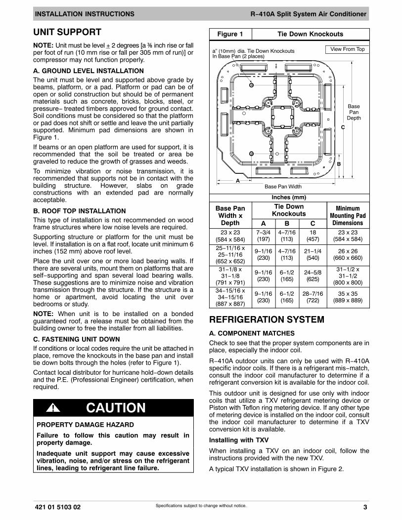
C. FASTENING UNIT DOWNIf conditions or local codes require the unit be attached inplace, remove the knockouts in the base pan and installtie down bolts through the holes (refer to Figure 1).
Contact local distributor for hurricane hold−down detailsand the P.E. (Professional Engineer) certification, whenrequired.
! CAUTIONPROPERTY DAMAGE HAZARD
Failure to follow this caution may result inproperty damage.
Inadequate unit support may cause excessivevibration, noise, and/or stress on the refrigerantlines, leading to refrigerant line failure.
Figure 1 Tie Down Knockouts
BasePan
Depth
C
B
ABase Pan Width
a” (10mm) dia. Tie Down KnockoutsIn Base Pan (2 places)
View From Top
Inches (mm)
Base PanWidth xDepth
Tie DownKnockouts
MinimumMounting PadDimensionsA B C
23 x 23(584 x 584)
7−3/4(197)
4−7/16(113)
18(457)
23 x 23(584 x 584)
25−11/16 x25−11/16
(652 x 652)
9−1/16(230)
4−7/16(113)
21−1/4(540)
26 x 26(660 x 660)
31−1/8 x31−1/8
(791 x 791)
9−1/16(230)
6−1/2(165)
24−5/8(625)
31−1/2 x31−1/2
(800 x 800)34−15/16 x34−15/16
(887 x 887)
9−1/16(230)
6−1/2(165)
28−7/16(722)
35 x 35(889 x 889)
REFRIGERATION SYSTEMA. COMPONENT MATCHESCheck to see that the proper system components are inplace, especially the indoor coil.
R−410A outdoor units can only be used with R−410Aspecific indoor coils. If there is a refrigerant mis−match,consult the indoor coil manufacturer to determine if arefrigerant conversion kit is available for the indoor coil.
This outdoor unit is designed for use only with indoorcoils that utilize a TXV refrigerant metering device orPiston with Teflon ring metering device. If any other typeof metering device is installed on the indoor coil, consultthe indoor coil manufacturer to determine if a TXVconversion kit is available.
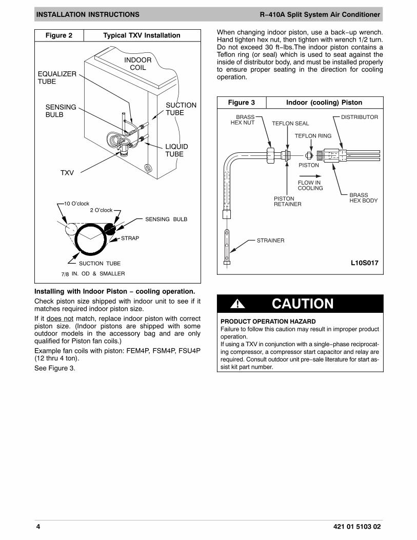
Installing with TXV
When installing a TXV on an indoor coil, follow theinstructions provided with the new TXV.
A typical TXV installation is shown in Figure 2.
INSTALLATION INSTRUCTIONS R−410A Split System Air Conditioner
4 421 01 5103 02
Figure 2 Typical TXV Installation
TXV
SENSINGBULB
EQUALIZERTUBE
INDOORCOIL
SUCTIONTUBE
LIQUIDTUBE
SENSING BULB
STRAP
SUCTION TUBE
IN. OD & SMALLER
10 O’clock2 O’clock
7/8
Installing with Indoor Piston − cooling operation.Check piston size shipped with indoor unit to see if itmatches required indoor piston size.If it does not match, replace indoor piston with correctpiston size. (Indoor pistons are shipped with someoutdoor models in the accessory bag and are onlyqualified for Piston fan coils.)Example fan coils with piston: FEM4P, FSM4P, FSU4P(12 thru 4 ton).
See Figure 3.
When changing indoor piston, use a back−up wrench.Hand tighten hex nut, then tighten with wrench 1/2 turn.Do not exceed 30 ft−lbs.The indoor piston contains aTeflon ring (or seal) which is used to seat against theinside of distributor body, and must be installed properlyto ensure proper seating in the direction for coolingoperation.
Figure 3 Indoor (cooling) Piston
TEFLON SEALBRASS
HEX NUT
STRAINER
PISTONRETAINER
BRASSHEX BODY
DISTRIBUTOR
PISTON
FLOW INCOOLING
TEFLON RING
L10S017
! CAUTIONPRODUCT OPERATION HAZARDFailure to follow this caution may result in improper productoperation.If using a TXV in conjunction with a single−phase reciprocat-ing compressor, a compressor start capacitor and relay arerequired. Consult outdoor unit pre−sale literature for start as-sist kit part number.

INSTALLATION INSTRUCTIONS R−410A Split System Air Conditioner
421 01 5103 02 5Specifications subject to change without notice.
B. REFRIGERANT LINE SETSThe refrigerant line set must be properly sized to assuremaximum efficiency and proper oil circulation.Refer to Product Specifications and Long LineApplications Guideline for line set sizing.NOTE: Total line set length must not exceed 200 feet (61m).A crankcase heater must be used when the refrigerantline length exceeds 80 feet (24.4 m).If outdoor unit is more than 10 feet (3 m) higher than theindoor coil, refer to the Long Line Applications Guidelinefor instructions.When the outdoor unit is higher than the indoor coil, thevertical separation must not exceed 100 feet (30 m).When the outdoor unit is lower than the indoor coil, thevertical separation must not exceed 50 feet (15.2 m).If it is necessary to add refrigerant line in the field, usedehydrated or dry, sealed, deoxidized, copperrefrigeration tubing. Do not use copper water pipe.Do not remove rubber plugs or caps from copper tubinguntil connections are ready to be made.Be extra careful when bending refrigeration tubing.Tubing can “kink” easily, and if this occurs, the entirelength of tubing must be replaced.
! WARNING
PERSONAL INJURY HAZARD
Failure to relieve system pressure could result inpersonal injury and/or death.
Relieve pressure and recover all refrigerant be-fore servicing existing equipment, and before fi-nal unit disposal. Use all service ports and openall flow−control devices, including solenoidvalves.
C. ROUTING AND SUSPENDING REFRIGERANTLINES
Run refrigerant lines as straight and direct as possible,avoiding unnecessary bends and turns. Always insulatethe entire suction line. Both lines should be insulatedwhen routed through an attic or when routed through anunderground raceway.When routing refrigerant lines through a foundation or wall,do not allow refrigerant lines to come in direct contact withthe building structure. Make openings large enough so thatlines can be wrapped with extra insulation. Fill all gaps withRTV caulk. This will prevent noise transmission betweenthe tubing and the foundation or wall.Along floor or ceiling joists, suspend refrigerant lines sothat they do not contact the building structure, waterpipes, or ductwork. Use insulated or suspension typehangers. Metal straps must be at least 1” (25 mm) wide toavoid cutting into the tube insulation. Keep the liquid andsuction lines separate. Refer to Figure 4.
! CAUTIONUNIT OPERATION HAZARD
Failure to follow this caution may result in im-proper product operation.
Do not leave system open to atmosphere any lon-ger than absolutely required for installation. Inter-nal system components − especially refrigerantoils − are extremely susceptible to moisture con-tamination. Keep ends of tubing sealed duringinstallation until the last possible moment.
Figure 4 Routing and Suspending Refrigerant Lines
INSULATION
SUCTION TUBE
LIQUID TUBE
OUTDOOR WALL INDOOR WALL
LIQUID TUBE
SUCTION TUBEINSULATION
CAULKHANGER STRAP
(AROUND SUCTIONTUBE ONLY)
JOIST
1” (25mm)MIN
THROUGH THE WALL SUSPENSION
INSTALLATION INSTRUCTIONS R−410A Split System Air Conditioner
6 421 01 5103 02
! CAUTIONUNIT OPERATION HAZARD
Failure to follow this caution may result in im-proper product operation.
Do not bury more than 36” (1m) of line set under-ground. Refrigerant may migrate to cooler buriedsection during extended periods of unit shut−down, causing refrigerant slugging and possiblecompressor damage at start−up.If ANY section of the line set is buried under-ground, provide a minimum 6” (152mm) verticalrise at the service valve.
D. OUTDOOR UNIT HIGHER THAN INDOOR UNITProper oil return to the compressor should be maintainedwith suction gas velocity. If velocities drop below 1500fpm (feet per minute), oil return will be decreased. Tomaintain suction gas velocity, do not upsize verticalsuction risers.
E. LIQUID LINE FILTER−DRIEROutdoor units are shipped with an appropriate filter−drierfor installation in the liquid line. Leave the plugs in thetube ends until the filter−drier is installed. The optimallocation for the filter−drier is close to the indoor coil.Install the filter−drier with the arrow pointing towards theindoor coil. Refer to Figure 5.
Figure 5 Liquid Line Filter−DrierInstalled at Indoor Coil
38−11−84Filter−Drier(arrow points towards indoor coil)
F. SERVICE VALVESService valves are closed and tube stubs are pluggedfrom the factory. Outdoor units are shipped with a
refrigerant charge sealed in the unit. Leave the servicevalves closed until all other refrigerant system work iscomplete or the charge will be lost. Leave the plugs inplace until line set tubing is ready to be inserted.
Service valve bodies are brass and tube stubs arecopper.
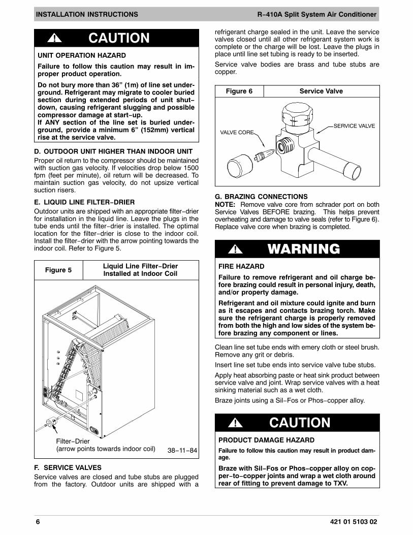
Figure 6 Service Valve
VALVE CORESERVICE VALVE
G. BRAZING CONNECTIONSNOTE: Remove valve core from schrader port on bothService Valves BEFORE brazing. This helps preventoverheating and damage to valve seals (refer to Figure 6).Replace valve core when brazing is completed.
! WARNING
FIRE HAZARD
Failure to remove refrigerant and oil charge be-fore brazing could result in personal injury, death,and/or property damage.
Refrigerant and oil mixture could ignite and burnas it escapes and contacts brazing torch. Makesure the refrigerant charge is properly removedfrom both the high and low sides of the system be-fore brazing any component or lines.
Clean line set tube ends with emery cloth or steel brush.Remove any grit or debris.
Insert line set tube ends into service valve tube stubs.
Apply heat absorbing paste or heat sink product betweenservice valve and joint. Wrap service valves with a heatsinking material such as a wet cloth.
Braze joints using a Sil−Fos or Phos−copper alloy.
! CAUTIONPRODUCT DAMAGE HAZARD
Failure to follow this caution may result in product dam-age.
Braze with Sil−Fos or Phos−copper alloy on cop-per−to−copper joints and wrap a wet cloth aroundrear of fitting to prevent damage to TXV.

INSTALLATION INSTRUCTIONS R−410A Split System Air Conditioner
421 01 5103 02 7Specifications subject to change without notice.
H. EVACUATING LINE SET AND INDOOR COILThe unit is shipped with a factory refrigerant charge. Theliquid line and suction line service valves have been closedafter final testing at the factory. Do not disturb these valvesuntil the line set and indoor coil have been evacuated andleak checked, or the charge in the unit may be lost.NOTE: Do not use any portion of the factory charge forpurging or leak testing. The factory charge is for filling thesystem only after a complete evacuation and leak checkhas been performed.
! CAUTIONPRODUCT DAMAGE HAZARD
Failure to follow this caution may result in product dam-age.
Never use the outdoor unit compressor as a vacu-um pump. Doing so may damage the compressor.
Line set and indoor coil should be evacuated using therecommended deep vacuum method of 500 microns. Ifdeep vacuum equipment is not available, the alternatetriple evacuation method may be used by following thespecified procedure.If vacuum must be interrupted during the evacuationprocedure, always break vacuum with dry nitrogen.Deep Vacuum MethodThe deep vacuum method requires a vacuum pumpcapable of pulling a vacuum to 500 microns and avacuum gauge capable of accurately measuring thisvacuum level. The deep vacuum method is the mostpositive way of assuring a system is free of air and water.Watch the vacuum gauge as the system is pulling down.The response of the gauge is an indicator of the conditionof the system (refer to Figure 7).With no leaks in the system, allow the vacuum pump torun for 30 minutes minimum at the deep vacuum level.
Figure 7 Deep Vacuum Gauge Responseand System Conditions
500
MINUTES0 1 2 4 6
1000
1500
LEAK INSYSTEM
VACUUM TIGHTTOO WET
TIGHTDRY SYSTEM
2000MIC
RO
NS
2500
3000
3500
4000
4500
5000
3 75
Triple Evacuation MethodThe triple evacuation method should only be used whensystem does not contain any water in liquid form andvacuum pump is only capable of pulling down to 28 inchesof mercury (711mm Hg). Refer to Figure 8 and proceed asfollows:
1. Pull system down to 28 inches of mercury(711mm Hg) and allow pump to continueoperating for an additional 15 minutes.
2. Close manifold valves or valve at vacuum pumpand shut off vacuum pump.
3. Connect a nitrogen cylinder and regulator tosystem and fill with nitrogen until system pressureis 2 psig.
4. Close nitrogen valve and allow system to stand for1 hour. During this time, dry nitrogen will diffusethroughout the system absorbing moisture.
5. Repeat this procedure as indicated in Figure 8.6. After the final evacuate sequence, confirm there
are no leaks in the system. If a leak is found,repeat the entire process after repair is made.
Figure 8 Triple Evacuation Sequence
CHECK FOR TIGHT, DRY SYSTEM(IF IT HOLDS DEEP VACUUM)
EVACUATE
BREAK VACUUM WITH DRY NITROGEN
WAIT
EVACUATE
CHARGE SYSTEM
BREAK VACUUM WITH DRY NITROGEN
EVACUATE
WAIT

INSTALLATION INSTRUCTIONS R−410A Split System Air Conditioner
8 421 01 5103 02
I. OPENING SERVICE VALVESOutdoor units are shipped with a refrigerant chargesealed in the unit. Opening the service valves releasesthis charge into the system.NOTE: Open the Suction service valve first. If the Liquidservice valve is opened first, oil from the compressormay be drawn into the indoor coil TXV, restrictingrefrigerant flow and affecting operation of the system.Remove Suction service valve cap and insert a hexwrench into the valve stem. Hold the valve body steadywith an end−wrench and back out the stem by turning thehex wrench counterclockwise. Turn the stem until it justcontacts the rolled lip of the valve body.
After the refrigerant charge has bled into the system,open the Liquid service valve.
NOTE: These are not back−seating valves. It is notnecessary to force the stem tightly against the rolled lip.
The service valve cap is a primary seal for the valve andmust be properly tightened to prevent leaks. Make surecap is clean and apply refrigerant oil to threads andsealing surface on inside of cap.Tighten cap finger tight and then tighten additional 6 of aturn (1 wrench flat) to properly seat the sealing surfaces.
J. GAUGE PORTSCheck for leaks at the schrader ports and tighten valvecores if necessary. Install plastic caps finger tight.
ELECTRICAL WIRING
! WARNING
ELECTRICAL SHOCK HAZARD
Failure to turn off the main (remote) electrical dis-connect device could result in personal injury ordeath.
Before installing, modifying or servicing system,turn OFF the main (remote) electrical disconnectdevice. There may be more than one disconnectdevice.
The supply voltage must be 208/230 volts (197 voltminimum to 253 volts maximum) 60 Hz single phase.
Outdoor units are approved for use with copperconductors only. Do not use aluminum wire.
Refer to unit rating plate for minimum circuit ampacityand circuit protection requirements.
Grounding
Permanently ground unit in accordance with the NationalElectrical Code and local codes or ordinances. Use acopper conductor of the correct size from the groundinglug in control box to a grounded connection in the servicepanel or a properly driven and electrically groundedground rod.
Wiring Connections
Make all outdoor electrical supply (Line Voltage)connections with raintight conduit and fittings. Mostcodes require a disconnect switch outdoors within sightof the unit. Consult local codes for special requirements.
Route electrical supply (Line Voltage) wiring throughknockout hole in bottom of Control Box. Connect wires toContactor and Ground Lug according to Wiring Diagramon unit. Refer to Figure 9.
Route thermostat wiring through rubber grommet inbottom of Control Box. Low voltage lead wires areprovided in the control box for connection to thermostatwires (use wire nuts). Refer to Wiring Diagram on unitand Figure 10 for low voltage wiring examples.
NOTE: Use No. 18 AWG (American Wire Gage)color−coded, insulated (35 ° C minimum) wire. Ifthermostat is located more than 100 feet (31 m) from unitas measured along the control voltage wires, use No. 16AWG color−coded wires to avoid excessive voltagedrop.
NOTE: Some models are factory equipped with ComfortAlert� Diagnostics device. If Comfort Alert is used as afield installed option, then a hot bundle must be run forproper connection.
Figure 9 Electrical Supply (Line Voltage) Connections
DISCONNECTPER NEC AND/OR
LOCAL CODESCONTACTOR
GROUNDLUG
FIELD GROUND
WIRING
FIELD POWERWIRING
11
23 or 13
L1
L2

INSTALLATION INSTRUCTIONS R−410A Split System Air Conditioner
421 01 5103 02 9Specifications subject to change without notice.
Figure 10 Typical Thermostat Connections
24 VAC HOT
24 VAC COM
R
C
G
W/W1
Y/Y2
R
C
C
THERMOSTAT FURNACE
Y
G
WHEAT STAGE 1
COOL STAGE 1
INDOOR FAN
AIR CONDITIONER
24 VAC HOT
24 VAC COM
R
C
G
W/W1
Y/Y2
R
C
C
THERMOSTAT FAN COIL
Y
G
W2HEAT STAGE 1
COOL STAGE 1
INDOOR FAN
AIR CONDITIONER
24 VAC HOT
24 VAC COM
R
C
G
W/W1
Y/Y2
R
C
THERMOSTAT FAN COIL
Y
G
W2HEAT STAGE 1
COOL STAGE 1
INDOOR FAN
AC with Comfort Alert
C
Y
START−UP PROCEDURE1. Set indoor thermostat selector switch to OFF.2. Turn ON all electrical disconnect devices.3. If unit has a crankcase heater, energize the heater
and wait 24 hours before proceeding.4. Set indoor thermostat at desired temperature. Be
sure setpoint is below indoor ambient temperatureor thermostat will not call for cooling.
5. Set indoor thermostat selector switch to COOL.Operate unit for minimum 15 minutes, then checkthe system refrigerant charge.
REFRIGERANT CHARGEFactory charge amount and desired subcooling areshown on unit rating plate. Charging method is shown oninformation plate inside unit.For TXV, use subcooling method.
For Piston, use superheat method.
To properly check or adjust charge, conditions must befavorable for subcooling or superheat charging.Favorable conditions exist when the outdoortemperature is between 70�F and 100�F (21�C and38�C), and the indoor temperature is between 70�F and80�F (21�C and 27�C). Follow the procedure below.
Unit is factory charged for 15 feet (4.6 m) of lineset.Adjust charge by adding or removing 0.6 oz/ft (17 g/mm)of 3/8 liquid line above or below 15 feet (4.6 m)respectively.
For standard refrigerant line lengths 80 feet (24.4 m) orless, allow system to operate in cooling mode at least 15minutes. If conditions are favorable, check systemcharge by super heat method for fixed metering deviceand subcooling method for TXV. If any adjustment isnecessary, adjust charge slowly and allow system tooperate for 15 minutes to stabilize before declaring aproperly charged system.
INSTALLATION INSTRUCTIONS R−410A Split System Air Conditioner
10 421 01 5103 02
If the indoor temperature is above 80�F (27�C), and theoutdoor temperature is in the favorable range, adjustsystem charge by weight based on line length and allowthe indoor temperature to drop to 80�F (27�C) beforeattempting to check system charge by subcoolingmethod as described above.
If the indoor temperature is below 70�F (21�C), or theoutdoor temperature is not in the favorable range, adjustcharge for line set length above or below 15 feet (4.6 m)only. Charge level should then be appropriate for thesystem to achieve rated capacity. The charge level couldthen be checked at another time when the both indoorand outdoor temperatures are in a more favorable range.
NOTE: If line length is beyond 80 feet (24.4 m) or greaterthan 20 feet (6.1 m) vertical separation, See Long LineGuideline for special charging requirements.
A. UNITS WITH COOLING MODE TXVUnits installed with cooling mode TXV require chargingby the subcooling method.
1. Operate unit a minimum of 15 minutes beforechecking charge.NOTE: If outdoor unit has a 2−speed fan motor,motor will operate in low speed when outdoorambient temperature is below 82�F. Pull one ofthe yellow low voltage wires off the fan control andthe unit will default to high speed fan for servicing.Reconnect wire after servicing.
2. Measure liquid service valve pressure byattaching an accurate gage to service port.
3. Measure liquid line temperature by attaching anaccurate thermistor type or electronicthermometer to liquid line near outdoor coil.
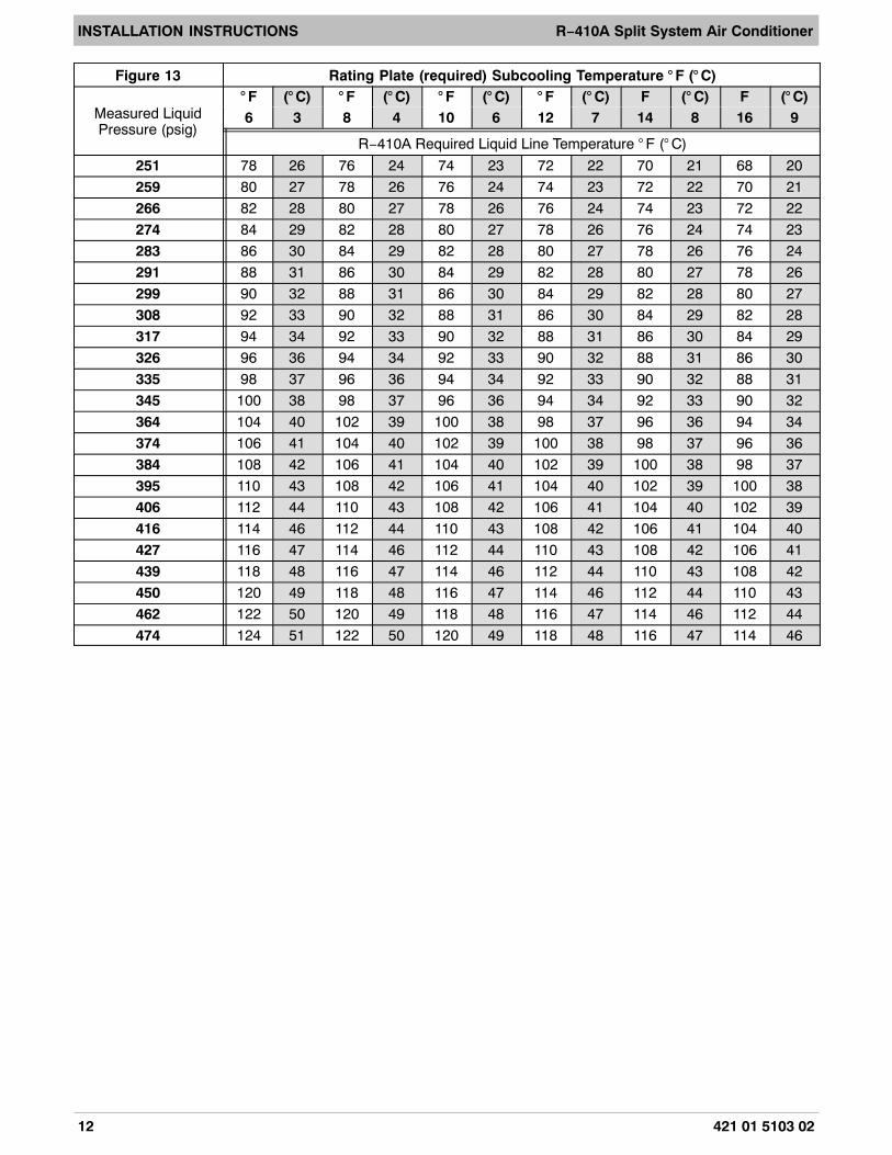
4. Refer to unit rating plate for required subcoolingtemperature.
5. Refer to Figure 13. Find the point where requiredsubcooling temperature intersects measuredliquid service valve pressure.
6. To obtain required subcooling temperature at aspecific liquid line pressure, add refrigerant ifliquid line temperature is higher than indicated orreclaim refrigerant if temperature is lower. Allow atolerance of �3�F (�1.7�C).
B. UNITS WITH INDOOR PISTONUnits installed with indoor pistons require charging by thesuperheat method.
The following procedure is valid when indoor airflow is
within �21 percent of its rated CFM.
1. Operate unit a minimum of 15 minutes beforechecking charge.
2. Measure suction pressure by attaching anaccurate gage to suction valve service port.
3. Measure suction temperature by attaching anaccurate thermistor type or electronicthermometer to suction line at service valve.
4. Measure outdoor air dry−bulb temperature withthermometer.
5. Measure indoor air (entering indoor coil) wet−bulbtemperature with a sling psychrometer.
6. Find outdoor temperature and evaporatorentering air wet−bulb temperature. At thisintersection, note superheat. Where a dash (−−)appears on the table, do not attempt to chargesystem under these conditions or refrigerantslugging may occur. Charge must be weighted in,adding or removing 0.6 oz/ft of 3/8 liquid lineabove or below 15 feet (4.6 m) respectively.
7. Find superheat temperature (from #6 above) andsuction pressure. At this intersection, note suctionline temperature.
8. If unit has a higher suction line temperature thancharted temperature, add refrigerant until chartedtemperature is reached.
9. If unit has a lower suction line temperature thancharted temperature, reclaim refrigerant untilcharted temperature is reached.
10. When adding refrigerant, charge in liquid form intosuction service port using a flow−restrictingdevice.
11. If outdoor air temperature or pressure at suctionvalve changes, charge to new suction linetemperature indicated on chart.
12. Optimum performance will be achieved whenthe operating charge produces 10�F suctionsuperheat at suction service valve with 95�F(35�C) outdoor ambient and 80�F (27�C) drybulb (67�F / 19�C) wet bulb) indoortemperature (DOE “A” test conditions) atrated airflow.

INSTALLATION INSTRUCTIONS R−410A Split System Air Conditioner
421 01 5103 02 11Specifications subject to change without notice.
Figure 11SUPERHEAT CHARGING TABLE
(SUPERHEAT ˚F AT LOW-SIDE SERVICE PORT)SUPERHEAT CHARGING TABLE
(SUPERHEAT ˚C AT LOW-SIDE SERVICE PORT)Outdoor
TempEVAPORATOR ENTEREING AIR ˚F AT WB Outdoor
TempEVAPORATOR ENTEREING AIR ˚C AT WB
˚F = Fahrenheit ˚C = Celsius
˚F 50 52 54 56 58 60 62 64 66 68 70 72 74 76 ˚C 10 11 12 13 14 16 17 18 19 20 21 22 23 24
55 9 12 14 17 20 23 26 29 32 35 37 40 42 45 13 5 7 8 9 11 13 14 16 18 19 21 22 23 25
60 7 10 12 15 18 21 24 27 30 33 35 38 40 43 16 4 6 7 8 10 12 13 15 17 18 19 21 22 24
65 6 10 13 16 19 21 24 27 30 33 36 38 41 18 3 6 7 9 11 12 13 15 17 18 20 21 23
70 7 10 13 16 19 21 24 27 30 33 36 39 21 4 6 7 9 11 12 13 15 17 18 20 22
75 6 9 12 15 18 21 24 28 31 34 37 24 3 5 7 8 10 12 13 16 17 19 21
80 5 8 12 15 18 21 25 28 31 35 27 3 4 7 8 10 12 14 16 17 19
85 8 11 15 19 22 26 30 33 29 4 6 8 11 12 14 17 18
90 5 9 13 16 20 24 27 31 32 3 5 7 9 11 13 15 17
95 6 10 14 18 22 25 29 35 3 6 8 10 12 14 16
100 8 12 15 20 23 27 38 4 7 8 11 13 15
105 5 9 13 17 22 26 41 3 5 7 9 12 14
110 6 11 15 20 25 43 3 6 8 11 14
115 8 14 18 23 46 4 8 10 13
*Optimum performance point, 95°F (35°C) outdoor ambient and (80°F / 27°C dry bulb), (67°F / 19°C wet bulb) indoor conditions. (DOE A Test Conditions)
Where a dash (--) appears do not attempt to charge system under these conditions or refrigerant slugging may occur. Charge must be weighed in.
Note: Superheat °F is at low-side service port, Allow a tolerance of ± 3°F (± 1.7°C)
Note: Indoor dry bulb between 70°F and 80°F (21°C and 27°C)
Figure 12 SUCTION PRESSURE AT SERVICE PORT PSIG SUCTION PRESSURE AT SERVICE PORT kPASUPER-
HEATTEMP F
108 112 117 121 126 131 139 141 146 SUPER-HEAT
TEMP C
743 774 805 836 869 902 957 971 1005REQUIRED SUCTION TUBE TEMPERATURE ˚F(MEASURED AT LOW-SIDE SERVICE PORT)
REQUIRED SUCTION TUBE TEMPERATURE ˚C(MEASURED AT LOW-SIDE SERVICE PORT)
0 35 37 39 41 43 45 47 49 51 0 2 3 4 5 6 7 8 9 112 37 39 41 43 45 47 49 51 53 1 3 4 5 6 7 8 9 11 124 39 41 43 45 47 49 51 53 55 2 4 5 6 7 8 9 11 12 136 41 43 45 47 49 51 53 55 57 3 5 6 7 8 9 11 12 13 148 43 45 47 49 51 53 55 57 59 4 6 7 8 9 11 12 13 14 1510 45 47 49 51 53 55 57 59 61 6 7 8 9 11 12 13 14 15 1612 47 49 51 53 55 57 59 61 63 7 8 9 11 12 13 14 15 16 1714 49 51 53 55 57 59 61 63 65 8 9 11 12 13 14 15 16 17 1816 51 53 55 57 59 61 63 65 67 9 11 12 13 14 15 16 17 18 1918 53 55 57 59 61 63 65 67 69 10 12 13 14 15 16 17 18 19 2120 55 57 59 61 63 65 67 69 71 11 13 14 15 16 17 18 19 21 2222 57 59 61 63 65 67 69 71 73 12 14 15 16 17 18 19 21 22 2324 59 61 63 65 67 69 71 73 75 13 15 16 17 18 19 21 22 23 2426 61 63 65 67 69 71 73 75 77 14 16 17 18 19 21 22 23 24 2528 63 65 67 69 71 73 75 77 79 16 17 18 19 21 22 23 24 25 2630 65 67 69 71 73 75 77 79 81 17 18 19 21 22 23 24 25 26 27
INSTALLATION INSTRUCTIONS R−410A Split System Air Conditioner
12 421 01 5103 02
Figure 13 Rating Plate (required) Subcooling Temperature ° F (° C)
Measured LiquidPressure (psig)
° F (° C) ° F (° C) ° F (° C) ° F (° C) F (° C) F (° C)6 3 8 4 10 6 12 7 14 8 16 9
R−410A Required Liquid Line Temperature ° F (° C)
251 78 26 76 24 74 23 72 22 70 21 68 20
259 80 27 78 26 76 24 74 23 72 22 70 21
266 82 28 80 27 78 26 76 24 74 23 72 22
274 84 29 82 28 80 27 78 26 76 24 74 23
283 86 30 84 29 82 28 80 27 78 26 76 24
291 88 31 86 30 84 29 82 28 80 27 78 26
299 90 32 88 31 86 30 84 29 82 28 80 27
308 92 33 90 32 88 31 86 30 84 29 82 28
317 94 34 92 33 90 32 88 31 86 30 84 29
326 96 36 94 34 92 33 90 32 88 31 86 30
335 98 37 96 36 94 34 92 33 90 32 88 31
345 100 38 98 37 96 36 94 34 92 33 90 32
364 104 40 102 39 100 38 98 37 96 36 94 34
374 106 41 104 40 102 39 100 38 98 37 96 36
384 108 42 106 41 104 40 102 39 100 38 98 37
395 110 43 108 42 106 41 104 40 102 39 100 38
406 112 44 110 43 108 42 106 41 104 40 102 39
416 114 46 112 44 110 43 108 42 106 41 104 40
427 116 47 114 46 112 44 110 43 108 42 106 41
439 118 48 116 47 114 46 112 44 110 43 108 42
450 120 49 118 48 116 47 114 46 112 44 110 43
462 122 50 120 49 118 48 116 47 114 46 112 44
474 124 51 122 50 120 49 118 48 116 47 114 46
INSTALLATION INSTRUCTIONS R−410A Split System Air Conditioner
421 01 5103 02 13Specifications subject to change without notice.
SEQUENCE OF OPERATIONWith power supplied to indoor and outdoor units,transformer is energized.On a call for cooling, the thermostat makes circuits R−Yand R−G. Circuit R−Y energizes contactor, startingoutdoor fan motor and compressor. Circuit R−Genergizes indoor unit blower relay, starting indoor blowermotor.When thermostat is satisfied, its contacts open,de−energizing contactor and blower relay. Compressorand motors stop.NOTE: If indoor unit is equipped with a time−delay relaycircuit, the blower runs an additional length of time toincrease system efficiency.
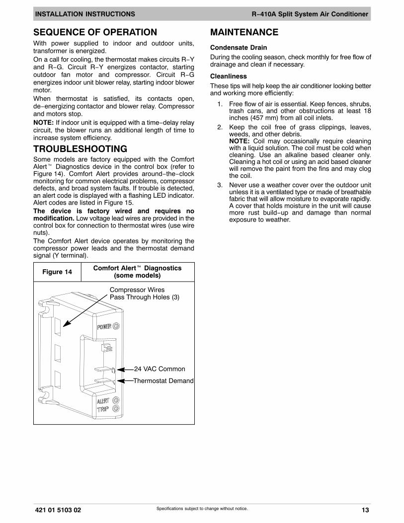
TROUBLESHOOTINGSome models are factory equipped with the ComfortAlert� Diagnostics device in the control box (refer toFigure 14). Comfort Alert provides around−the−clockmonitoring for common electrical problems, compressordefects, and broad system faults. If trouble is detected,an alert code is displayed with a flashing LED indicator.Alert codes are listed in Figure 15.The device is factory wired and requires nomodification. Low voltage lead wires are provided in thecontrol box for connection to thermostat wires (use wirenuts).The Comfort Alert device operates by monitoring thecompressor power leads and the thermostat demandsignal (Y terminal).
Figure 14 Comfort Alert� Diagnostics(some models)
24 VAC Common
Thermostat Demand
Compressor WiresPass Through Holes (3)
MAINTENANCE
Condensate DrainDuring the cooling season, check monthly for free flow ofdrainage and clean if necessary.
CleanlinessThese tips will help keep the air conditioner looking betterand working more efficiently:
1. Free flow of air is essential. Keep fences, shrubs,trash cans, and other obstructions at least 18inches (457 mm) from all coil inlets.
2. Keep the coil free of grass clippings, leaves,weeds, and other debris.NOTE: Coil may occasionally require cleaningwith a liquid solution. The coil must be cold whencleaning. Use an alkaline based cleaner only.Cleaning a hot coil or using an acid based cleanerwill remove the paint from the fins and may clogthe coil.
3. Never use a weather cover over the outdoor unitunless it is a ventilated type or made of breathablefabric that will allow moisture to evaporate rapidly.A cover that holds moisture in the unit will causemore rust build−up and damage than normalexposure to weather.
INSTALLATION INSTRUCTIONS R−410A Split System Air Conditioner
14 421 01 5103 02
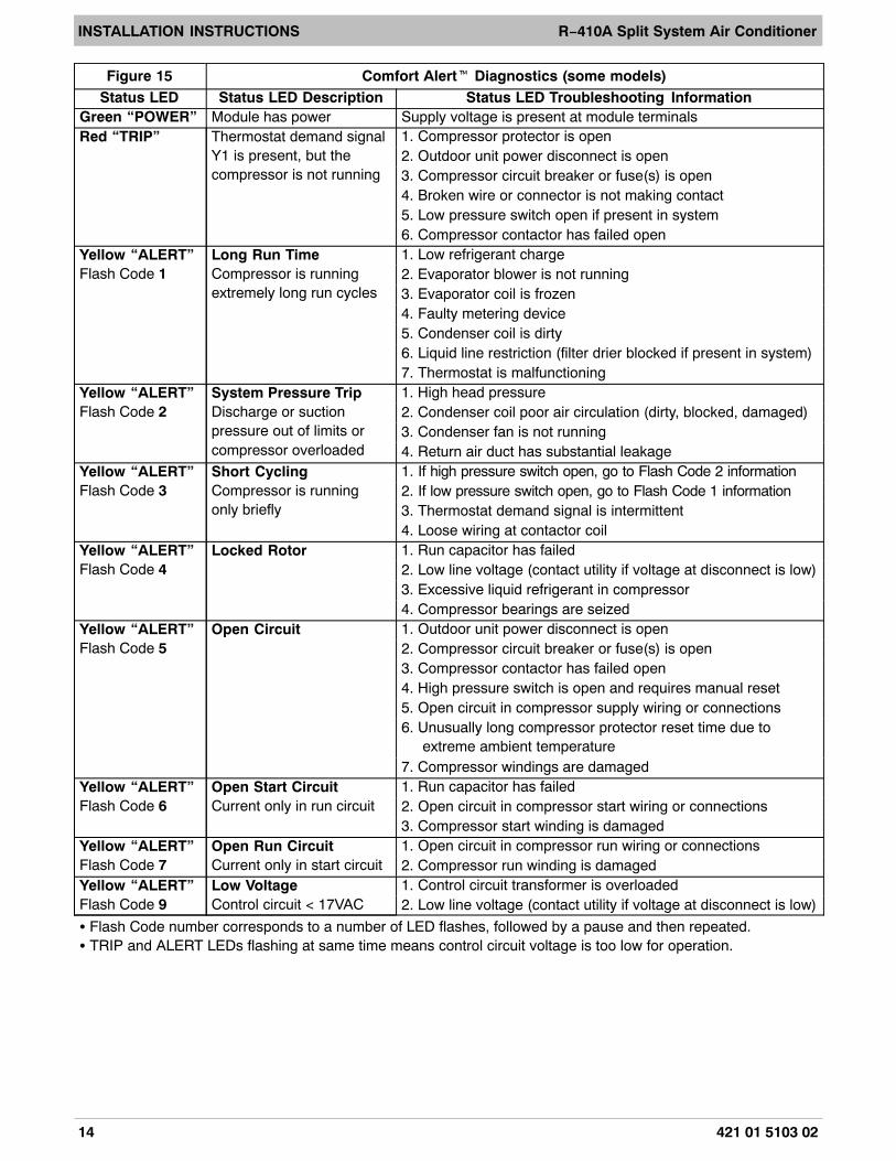
Figure 15 Comfort Alert� Diagnostics (some models)Status LED Status LED Description Status LED Troubleshooting Information
Green “POWER” Module has power Supply voltage is present at module terminalsRed “TRIP” Thermostat demand signal
Y1 is present, but thecompressor is not running
1. Compressor protector is open2. Outdoor unit power disconnect is open3. Compressor circuit breaker or fuse(s) is open4. Broken wire or connector is not making contact5. Low pressure switch open if present in system6. Compressor contactor has failed open
Yellow “ALERT”Flash Code 1
Long Run TimeCompressor is runningextremely long run cycles
1. Low refrigerant charge2. Evaporator blower is not running3. Evaporator coil is frozen4. Faulty metering device5. Condenser coil is dirty6. Liquid line restriction (filter drier blocked if present in system)7. Thermostat is malfunctioning
Yellow “ALERT”Flash Code 2
System Pressure TripDischarge or suctionpressure out of limits orcompressor overloaded
1. High head pressure2. Condenser coil poor air circulation (dirty, blocked, damaged)3. Condenser fan is not running4. Return air duct has substantial leakage
Yellow “ALERT”Flash Code 3
Short CyclingCompressor is runningonly briefly
1. If high pressure switch open, go to Flash Code 2 information2. If low pressure switch open, go to Flash Code 1 information3. Thermostat demand signal is intermittent4. Loose wiring at contactor coil
Yellow “ALERT”Flash Code 4
Locked Rotor 1. Run capacitor has failed2. Low line voltage (contact utility if voltage at disconnect is low)3. Excessive liquid refrigerant in compressor4. Compressor bearings are seized
Yellow “ALERT”Flash Code 5
Open Circuit 1. Outdoor unit power disconnect is open2. Compressor circuit breaker or fuse(s) is open3. Compressor contactor has failed open4. High pressure switch is open and requires manual reset5. Open circuit in compressor supply wiring or connections6. Unusually long compressor protector reset time due to
extreme ambient temperature7. Compressor windings are damaged
Yellow “ALERT”Flash Code 6
Open Start CircuitCurrent only in run circuit
1. Run capacitor has failed2. Open circuit in compressor start wiring or connections3. Compressor start winding is damaged
Yellow “ALERT”Flash Code 7
Open Run CircuitCurrent only in start circuit
1. Open circuit in compressor run wiring or connections2. Compressor run winding is damaged
Yellow “ALERT”Flash Code 9
Low VoltageControl circuit < 17VAC
1. Control circuit transformer is overloaded2. Low line voltage (contact utility if voltage at disconnect is low)
� Flash Code number corresponds to a number of LED flashes, followed by a pause and then repeated.� TRIP and ALERT LEDs flashing at same time means control circuit voltage is too low for operation.
INSTALLATION INSTRUCTIONS R−410A Split System Air Conditioner
421 01 5103 02 15Specifications subject to change without notice.
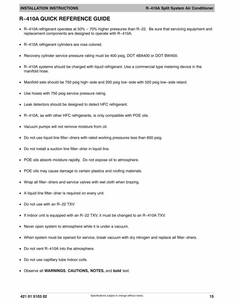
R−410A QUICK REFERENCE GUIDE
• R−410A refrigerant operates at 50% − 70% higher pressures than R−22. Be sure that servicing equipment andreplacement components are designed to operate with R−410A.
• R−410A refrigerant cylinders are rose colored.
• Recovery cylinder service pressure rating must be 400 psig, DOT 4BA400 or DOT BW400.
• R−410A systems should be charged with liquid refrigerant. Use a commercial type metering device in themanifold hose.
• Manifold sets should be 750 psig high−side and 200 psig low−side with 520 psig low−side retard.
• Use hoses with 750 psig service pressure rating.
• Leak detectors should be designed to detect HFC refrigerant.
• R−410A, as with other HFC refrigerants, is only compatible with POE oils.
• Vacuum pumps will not remove moisture from oil.
• Do not use liquid line filter−driers with rated working pressures less than 600 psig.
• Do not install a suction line filter−drier in liquid line.
• POE oils absorb moisture rapidly. Do not expose oil to atmosphere.
• POE oils may cause damage to certain plastics and roofing materials.
• Wrap all filter−driers and service valves with wet cloth when brazing.
• A liquid line filter−drier is required on every unit.
• Do not use with an R−22 TXV.
• If indoor unit is equipped with an R−22 TXV, it must be changed to an R−410A TXV.
• Never open system to atmosphere while it is under a vacuum.
• When system must be opened for service, break vacuum with dry nitrogen and replace all filter−driers.
• Do not vent R−410A into the atmosphere.
• Do not use capillary tube indoor coils.
• Observe all WARNINGS, CAUTIONS, NOTES, and bold text.
INSTALLATION INSTRUCTIONS R−410A Split System Air Conditioner
16 421 01 5103 02Copyright 2015 International Comfort ProductsLewisburg, TN 37091 USA