Catalog 410A
48
® Catalog 410A Energy Conscious A/C Solutions April 2011 / Catalog 410A
-
Upload
khangminh22 -
Category
Documents
-
view
0 -
download
0
Transcript of Catalog 410A
®
Catalog 410AEnergy Conscious A/C Solutions
April 2011 / Catalog 410A
Page 2 — CATALOG 410A
Condensed Catalog 410A April2011
This condensed catalog contains product specifically for R-410A applications. By including a minimum of engineering informa-tion we are able to provide a concise reference to pertinent data and specifications on Sporlan R-410A products. For additional
engineering information, a complete Sporlan Catalog or CD, please contact your nearest Sporlan Sales Office, Authorized Sporlan Wholesaler or log on to www.sporlan.com.
Accumulators . . . . . . . . . . . . . . . . . . . . . . . . . . . . . . . . . . . . . . . . . . . . . . . . . . . . . . . . . . . . . 30 . 40-10-7 .
Acid .Test .Kits . . . . . . . . . . . . . . . . . . . . . . . . . . . . . . . . . . . . . . . . . . . . . . . . . . . . . . . . . . . . . 33 . 40-10 .
Auxiliary .Side .Connectors . . . . . . . . . . . . . . . . . . . . . . . . . . . . . . . . . . . . . . . . . . . . . . . . . . 10 . 20-10
Catch-All® .Filter-Driers .Liquid .& .Suction .Line . . . . . . . . . . . . . . . . . . . . . . . . . . . . . . . . . 23 . 40-10
Discharge .Bypass .Valves . . . . . . . . . . . . . . . . . . . . . . . . . . . . . . . . . . . . . . . . . . . . . . . . . . . .37 . 90-40
Electronic .Temperature .Control .Systems . . . . . . . . . . . . . . . . . . . . . . . . . . . . . . . . . . . . . .41 . 100-9, .100-20, .100-20-1, . . . . . . . . . . . . . . . . . . . . . . . . . . . . . . . . . . . . . . . . . . . . . . . . . . . . . . . . . . . . . . . . . . . . . . . . . . . . . . . . . . . . . . . . . . . . . . . . . . . . . . . . . . . . . . . . . . . . . . . . . . . . . . . . . . . . . . . . . . . . . . . . . . . . . . . . . . . . . . . . . . . . . . . . . . . . . 100-40, .100-50-1 . . . . . . . . . . . . . . . . . . . . . . . . . . . . . . . . . . . . . . . . . . . . . . . . . . . . . . . . . . . . . . . . . . . . . . . . . . . . . 100-50-2 .& .100-60 .
Head .Pressure .Control .Valves . . . . . . . . . . . . . . . . . . . . . . . . . . . . . . . . . . . . . . . . . . . . . . . .34 . 90-30 .
Pressure-Temperature .Chart . . . . . . . . . . . . . . . . . . . . . . . . . . . . . . . . . . . . . . . . . . . . . . . . .46 . Form .10-135 .
Refrigerant .Distributors . . . . . . . . . . . . . . . . . . . . . . . . . . . . . . . . . . . . . . . . . . . . . . . . . . . . . .10 . 20-10
Reversible .Heat .Pump .Filter-Driers . . . . . . . . . . . . . . . . . . . . . . . . . . . . . . . . . . . . . . . . . . .28 . 40-10
See•All® .Moisture .& .Liquid .Indicators . . . . . . . . . . . . . . . . . . . . . . . . . . . . . . . . . . . . . . . .32 . 70-10
Solenoid .Valves . . . . . . . . . . . . . . . . . . . . . . . . . . . . . . . . . . . . . . . . . . . . . . . . . . . . . . . . . . . .13 . 30-10
Suction .Filters . . . . . . . . . . . . . . . . . . . . . . . . . . . . . . . . . . . . . . . . . . . . . . . . . . . . . . . . . . . . . .33 . 80-10
Thermostatic .Expansion .Valves . . . . . . . . . . . . . . . . . . . . . . . . . . . . . . . . . . . . . . . . . . . . . . 3 . 10-9, .10-10 .& .10-10-8
Three .Way .Heat .Reclaim .Valves . . . . . . . . . . . . . . . . . . . . . . . . . . . . . . . . . . . . . . . . . . . . . 20 . 30-20
Terms .of .Sale .With .Warranty .Limitations . . . . . . . . . . . . . . . . . . . . . . . . . . . . . . . . . . . . . 47
CONTENTS Page
*For complete product informationsee Bulletin number listed below.
⚠WARNING – USER RESPONSIBILITYFailure or improper selection or improper use of the products described herein or related items can cause death, personal injury and property damage.
This document and other information from Parker Hannifin Corporation, its subsidiaries and authorized distributors provide product or system options for further investigation by users having technical expertise.
The user, through its own analysis and testing, is solely responsible for making the final selection of the system and components and assuring that all performance, endurance, maintenance, safety and warning requirements of the application are met. The user must analyze all aspects of the application, follow applicable industry standards, and follow the information concerning the product in the current product catalog and in any other materials provided from Parker or its subsidiaries or authorized distributors.
To the extent that Parker or its subsidiaries or authorized distributors provide component or system options based upon data or specifications provided by the user, the user is responsible for determining that such data and specifications are suitable and sufficient for all applications and reasonably foreseeable uses of the components or systems.
OFFER OF SALE
The items described in this document are hereby offered for sale by Parker Hannifin Corporation, its subsidiaries or its authorized distributors. This offer and its acceptance are governed by the provisions stated in the detailed “Offer of Sale” available at www.parker.com.
*To request individual Sporlan Product Bulletins, contact your nearest Sporlan Sales Office or Wholesaler, write Parker Hannifin, Sporlan Division, Washington, Missouri or visit our website at www.sporlan.com.
FOR USE ON REFRIGERATION and/or AIR CONDITIONING SYSTEMS ONLYCatalog 410A, April 2011 supersedes Catalog 410A dated January 2009 and all prior publications.
CATALOG 410A — Page 3
Thermostatic Expansion Valves 410A
VALVE TYPECONNECTIONS - Inches EXTERNAL
EQUALIZER VALVE DESCRIPTION AND APPLICATIONInlet Outlet
ERZE
3/8 .ODF1/2 .ODF5/8 .ODF7/8 .ODF
3/8 .ODF1/2 .ODF5/8 .ODF7/8 .ODF
1-1/8 .ODF1-3/8 .ODF
1/4” .ODFor
1/8” .ODF
CapillaryTube .Lengths
AvailableWith
OR .Without1/4” .SAEFlare .Nut
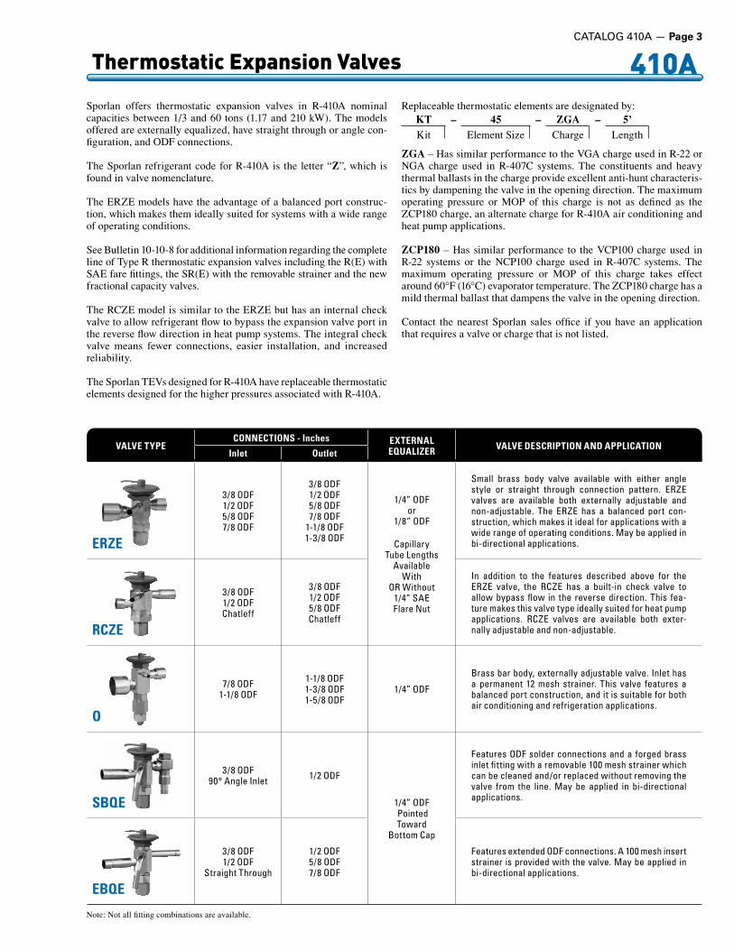
Small . brass . body . valve . available . with . either . angle .style . or . straight . through . connection . pattern . . ERZE .valves . are . available . both . externally . adjustable . and .non-adjustable . . The . ERZE . has . a . balanced . port . con-struction, .which .makes .it .ideal .for .applications .with .a .wide .range .of .operating .conditions . .May .be .applied .in .bi-directional .applications .
RCZE
3/8 .ODF1/2 .ODFChatleff
3/8 .ODF1/2 .ODF5/8 .ODFChatleff
In . addition . to . the . features . described . above . for . the .ERZE . valve, . the . RCZE . has . a . built-in . check . valve . to .allow . bypass . flow . in . the . reverse . direction . . This . fea-ture .makes .this .valve .type .ideally .suited .for .heat .pump .applications . . RCZE . valves . are . available . both . exter-nally .adjustable .and .non-adjustable .
O
7/8 .ODF1-1/8 .ODF
1-1/8 .ODF1-3/8 .ODF1-5/8 .ODF
1/4” .ODF
Brass .bar .body, .externally .adjustable .valve . .Inlet .has .a . permanent . 12 . mesh . strainer . . This . valve . features . a .balanced .port .construction, .and .it .is .suitable .for .both .air .conditioning .and .refrigeration .applications .
SBQE
3/8 .ODF90° .Angle .Inlet 1/2 .ODF
1/4” .ODF .PointedToward
Bottom .Cap
Features .ODF .solder .connections .and .a . forged .brass .inlet .fitting .with .a .removable .100 .mesh .strainer .which .can .be .cleaned .and/or .replaced .without .removing .the .valve . from . the . line . . May . be . applied . in . bi-directional .applications .
EBQE
3/8 .ODF1/2 .ODF
Straight .Through
1/2 .ODF5/8 .ODF7/8 .ODF
Features .extended .ODF .connections . .A .100 .mesh .insert .strainer . is .provided .with .the .valve . .May .be .applied . in .bi-directional .applications .
Sporlan offers thermostatic expansion valves in R-410A nominal capacities between 1/3 and 60 tons (1.17 and 210 kW). The models offered are externally equalized, have straight through or angle con-figuration, and ODF connections.
The Sporlan refrigerant code for R-410A is the letter “Z”, which is found in valve nomenclature.
The ERZE models have the advantage of a balanced port construc-tion, which makes them ideally suited for systems with a wide range of operating conditions.
See Bulletin 10-10-8 for additional information regarding the complete line of Type R thermostatic expansion valves including the R(E) with SAE fare fittings, the SR(E) with the removable strainer and the new fractional capacity valves.
The RCZE model is similar to the ERZE but has an internal check valve to allow refrigerant flow to bypass the expansion valve port in the reverse flow direction in heat pump systems. The integral check valve means fewer connections, easier installation, and increased reliability.
The Sporlan TEVs designed for R-410A have replaceable thermostatic elements designed for the higher pressures associated with R-410A.
Replaceable thermostatic elements are designated by:
ZGA – Has similar performance to the VGA charge used in R-22 or NGA charge used in R-407C systems. The constituents and heavy thermal ballasts in the charge provide excellent anti-hunt characteris-tics by dampening the valve in the opening direction. The maximum operating pressure or MOP of this charge is not as defined as the ZCP180 charge, an alternate charge for R-410A air conditioning and heat pump applications.
ZCP180 – Has similar performance to the VCP100 charge used in R-22 systems or the NCP100 charge used in R-407C systems. The maximum operating pressure or MOP of this charge takes effect around 60°F (16°C) evaporator temperature. The ZCP180 charge has a mild thermal ballast that dampens the valve in the opening direction.
Contact the nearest Sporlan sales office if you have an application that requires a valve or charge that is not listed.
Note: Not all fitting combinations are available.
KT – 45 – ZGA – 5’Kit Element Size Charge Length

Page 4 — CATALOG 410A
410A Thermostatic Expansion Valves
The ERZE valve is an externally adjustable balance ported TEV designed for R-410A air conditioning applications. This makes the ERZE valve an excellent replacement for all OEM BI and BBI valves as well as other applications requiring a R-410A expansion valve such as I and RI valves. The ERZE valve utilizes the KT-45 element design for the higher pressures of R-410A. This valve may also be applied in bi-directional applications.
Type ERZEKnife Edge JointStandard Cap Tube Length 30 in. (76 cm)
VALVETYPE
NOMINAL CAPACITY
(kW)
EVAPORATOR TEMPERATURE °C5 -5 -15
PRESSURE DROP ACROSS VALVE (bar)11 14 14
ERZE-1-GA 4.20 4 .20 4 .64 4 .25ERZE-1-1/2-GA 7.35 7 .35 8 .11 7 .44ERZE-2-GA 9.66 9 .66 10 .7 9 .77ERZE-3-GA 13.4 13 .4 14 .8 13 .6ERZE-4-GA 17.6 17 .6 19 .5 17 .8ERZE-5-GA 21.0 21 .0 23 .2 21 .2ERZE-6-GA 25.2 25 .2 27 .8 23 .7ERZE-8-GA 33.6 33 .6 37 .1 34 .0ERZE-12-1/2-GA 43.8 43 .8 48 .4 44 .3ERZE-15-GA 50.8 50 .8 56 .1 51 .4
VALVETYPE
NOMINAL CAPACITY
(Tons)
EVAPORATOR TEMPERATURE °F40 20 0
PRESSURE DROP ACROSS VALVE (psi)160 200 200
ERZE-1-GA 1 1 .2 1 .3 1 .2ERZE-1-1/2-GA 1-1/2 2 .1 2 .3 2 .0ERZE-2-GA 2 2 .7 3 .0 2 .7ERZE-3-GA 3 3 .8 4 .1 3 .7ERZE-4-GA 4 5 .0 5 .4 4 .9ERZE-5-GA 5 5 .9 6 .5 5 .8ERZE-6-GA 6 7 .1 7 .8 6 .3ERZE-8-GA 8 9 .5 10 .4 9 .3ERZE-12-1/2-GA 12-1/2 12 .3 13 .5 12 .1ERZE-15-GA 15 14 .3 15 .7 14 .0
Capacities Tons n psi n °F kW n bar n °C
LIQUID TEMPERATURE ENTERING TEV °F40 50 60 70 80 90 100 110 120 130 140
CORRECTION FACTOR, CF LIQUID TEMPERATURE1 .39 1 .31 1 .23 1 .17 1 .12 1 .06 1 .00 0 .94 0 .88 0 .82 0 .76
LIQUID TEMPERATURE ENTERING TEV °C5 10 15 20 25 30 35 40 45 50 55 60
CORRECTION FACTOR, CF LIQUID TEMPERATURE1 .46 1 .39 1 .32 1 .25 1 .18 1 .11 1 .04 0 .97 0 .89 0 .81 0 .72 0 .62
EVAPORATORTEMPERATURE
°F
PRESSURE DROP ACROSS TEV (psi)
80 120 160 200 240 280 320 360
CORRECTION FACTOR, CF PRESSURE DROP
40° 0 .71 0 .87 1 .00 1 .12 1 .22 1 .32 1 .41 1 .5020° 0 .63 0 .77 0 .89 1 .00 1 .10 1 .18 1 .26 1 .340° 0 .63 0 .77 0 .89 1 .00 1 .10 1 .18 1 .26 1 .34
EVAPORATORTEMPERATURE
°C
PRESSURE DROP ACROSS TEV (bar)
8 10 11 12 13 14 16 18 20
CORRECTION FACTOR, CF PRESSURE DROP
5° 0 .85 0 .95 1 .00 1 .04 1 .09 1 .13 1 .21 1 .28 1 .35-5° 0 .76 0 .85 0 .89 0 .93 0 .96 1 .00 1 .07 1 .13 1 .20-15° 0 .76 0 .85 0 .89 0 .93 0 .96 1 .00 1 .07 1 .13 1 .20
1.94”49 mm
A B
F
E
D
Cap Tube30”
76 cm
THERMOSTATICCHARGE
Inches mm
ZCP180 0 .50 .OD .x .3 .00 13 .OD .x .76ZGA 0 .75 .OD .x .2 .00 19 .OD .x .51
Bulb Sizes
30°
C1/4” ODF ExternalEqualizerConnection
Top View
VALVETYPE
FITTING SIZE**Inches
Inches mmA B C D E F A B C D E F
ERZE-1, 1-1/2 & 2*
3/8 ODF 1 .69 1 .35
1 .81 2 .17 3 .53 1 .83
42 .9 34 .3
46 .0 55 .1 89 .7 46 .5
1/2 ODF 1 .75* 1 .35 44 .4* 34 .35/8 ODF – 2 .51 – 63 .8
ERZE-3, 4, 5, 6 & 8
3/8 ODF 1 .69 – 42 .9 –1/2 ODF 1 .75 1 .35 44 .5 34 .35/8 ODF 1 .29 2 .51 32 .8 63 .87/8 ODF – 2 .41 – 61 .2
ERZE-12-1/2 & 15
5/8 ODF 1 .52 –
1 .90 2 .30 3 .79 1 .83
38 .6 –
48 .3 58 .4 96 .3 46 .57/8 ODF 2 .08 – 52 .8 –
5/8 ODF Ext. – 2 .51 – 63 .87/8 ODF Ext. – 2 .51 – 63 .8
1-1/8 ODF Ext. – 2 .51 – 63 .8
Dimensions Connections
*1/2 ODF inlet available on 2 ton valves only. ** Not all fitting combinations are available.
TypeERZE

CATALOG 410A — Page 5
Thermostatic Expansion Valves 410A
VALVETYPE
NOMINAL CAPACITY
(kW)
EVAPORATOR TEMPERATURE °C5 -5 -15
PRESSURE DROP ACROSS VALVE (bar)11 14 14
RCZE-1-GA 4.20 4 .20 4 .64 4 .25RCZE-1-1/2-GA 7.35 7 .35 8 .11 7 .44RCZE-2-GA 9.66 9 .66 10 .7 9 .77RCZE-3-GA 13.4 13 .4 14 .8 13 .6RCZE-4-GA 17.6 17 .6 19 .5 17 .8RCZE-5-GA 21.0 21 .0 23 .2 21 .2RCZE-6-GA 25.2 25 .2 27 .8 23 .7
VALVETYPE
NOMINAL CAPACITY
(Tons)
EVAPORATOR TEMPERATURE °F40 20 0
PRESSURE DROP ACROSS VALVE (psi)160 200 200
RCZE-1-GA 1 1 .2 1 .3 1 .2RCZE-1-1/2-GA 1-1/2 2 .1 2 .3 2 .0RCZE-2-GA 2 2 .7 3 .0 2 .7RCZE-3-GA 3 3 .8 4 .1 3 .7RCZE-4-GA 4 5 .0 5 .4 4 .9RCZE-5-GA 5 5 .9 6 .5 5 .8RCZE-6-GA 6 7 .1 7 .8 6 .3
Capacities Tons n psi n °F kW n bar n °C
Type RCZEKnife Edge JointStandard Cap Tube Length 30 in. (76 cm)
The RCZE valve is an externally adjust-able balance ported TEV with an internal check valve for heat pump applications. This makes the RCZE valve an excellent replace-ment for all OEM CBI and CBBI valves as well as other applications requiring a R-410A expansion valve on heat pumps. The RCZE valve may also be used on air conditioning (cool-ing only) applications. This allows you to reduce inventory to also replace the I, RI, BI and BBI valves. The RCZE valves utilize the KT-45 element design for the higher pressures of R-410A systems.
LIQUID TEMPERATURE ENTERING TEV °F40 50 60 70 80 90 100 110 120 130 140
CORRECTION FACTOR, CF LIQUID TEMPERATURE1 .39 1 .31 1 .23 1 .17 1 .12 1 .06 1 .00 0 .94 0 .88 0 .82 0 .76
LIQUID TEMPERATURE ENTERING TEV °C5 10 15 20 25 30 35 40 45 50 55 60
CORRECTION FACTOR, CF LIQUID TEMPERATURE1 .46 1 .39 1 .32 1 .25 1 .18 1 .11 1 .04 0 .97 0 .89 0 .81 0 .72 0 .62
C
D
3.66”93 mm
1.94”49 mm
Cap Tube30”
76 cm
1.81”46 mm
2.30”58 mm
A B
1/4” ODF1.90”
48 mm
30°VALVETYPE
FITTING SIZE**Inches
Inches mmA B A B
RCZE-1, 1-1/2 & 2
3/8 ODF 1 .92 1 .45 48 .8 36 .81/2 ODF 1 .98* 1 .45 50 .3 36 .85/8 ODF – 1 .53 – 38 .9
RCZE-3, 4, 5 & 6
3/8 ODF 1 .92 1 .45 48 .8 36 .81/2 ODF 1 .98 1 .45 50 .3 36 .85/8 ODF – 1 .53 – 38 .9
RCZE Chatleff Fitting 1 .89 1 .71 48 .0 43 .4
DimensionsConnections
THERMOSTATICCHARGE
Inches mmC D C D
ZCP180 0 .50 3 .00 13 76ZGA 0 .75 2 .00 19 51
Bulb Sizes
Top View
ChatleffFitting Option
*1/2 ODF inlet available on 2 ton valves only.** Not all fitting combinations are available.
TypeRCZE
EVAPORATORTEMPERATURE
°F
PRESSURE DROP ACROSS TEV (psi)
80 120 160 200 240 280 320 360
CORRECTION FACTOR, CF PRESSURE DROP
40° 0 .71 0 .87 1 .00 1 .12 1 .22 1 .32 1 .41 1 .5020° 0 .63 0 .77 0 .89 1 .00 1 .10 1 .18 1 .26 1 .340° 0 .63 0 .77 0 .89 1 .00 1 .10 1 .18 1 .26 1 .34
EVAPORATORTEMPERATURE
°C
PRESSURE DROP ACROSS TEV (bar)
8 10 11 12 13 14 16 18 20
CORRECTION FACTOR, CF PRESSURE DROP
5° 0 .85 0 .95 1 .00 1 .04 1 .09 1 .13 1 .21 1 .28 1 .35-5° 0 .76 0 .85 0 .89 0 .93 0 .96 1 .00 1 .07 1 .13 1 .20-15° 0 .76 0 .85 0 .89 0 .93 0 .96 1 .00 1 .07 1 .13 1 .20

Page 6 — CATALOG 410A
410A Thermostatic Expansion Valves
2.31”59 mm
D
C
C
1.70”43 mm
A B
2.43”62 mm
E
4.14”105 mm
Cap Tube5’
1.5 m
Sporlan Type O Valve is a brass bar body, externally adjustable valve with ODF solder connections. The thermostatic element is replaceable, and the inlet connection has a permanent 12 mesh strainer. This valve type features a balanced port construction, and it is designed for both air conditioning and refrigeration applications. A synthetic seating surface provides tight shut-off during sytem off periods.
This valve type has two body styles: a small body which provides capacities up to 35 tons (120 kW) R-410A, and a large body which extends capacities up to 60 tons (210 kW) R-410A.
Refrigerant distributors that will mate directly to this valve are listed below. Refer to Sporlan Bulletin 20-10 for additional application information on this subject.
Outlet Connections Distributors1-1/8” ODF 1115, 1116, 1655R1-3/8” ODF 1117, 1126, 1128, 1657R1-5/8” ODF 1125, 1127, 1143, 1659R
STRAIGHT THRUODF SOLDER
Inches mmA B C A B C
7/8 2 .09 – 0 .75 53 – 19
1-1/8 2 .21 2 .23 0 .91 56 57 23
1-3/8 – 2 .39 0 .97 – 61 25
Dimensions Type O with Number 85 ElementFor use on 20 thru 35 Ton Valves
BA
2.31”59 mm
C
C
5.52”140 mm
1.93”49 mm
D
E
2.90”74 mm
Cap Tube5’
1.5 m
1/4” ODF ExternalEqualizerConnection
1.40”36 mm1/4“ ODF
Top View
1.59”40 mm1/4“ ODF
1/4” ODF ExternalEqualizerConnection
Top View
THERMOSTATICCHARGE
Inches mmD E D E
ZGA 0 .75 2 .00 19 51
Bulb Sizes
STRAIGHT THRUODF SOLDER
Inches mmA B C A B C
1-1/8 2 .69 – 0 .91 68 – 23
1-3/8 – 2 .84 0 .97 – 72 25
1-5/8 – 3 .12 1 .09 – 79 28
Connections
THERMOSTATICCHARGE
Inches mmD E D E
ZGA 0 .75 2 .00 19 51
Bulb Sizes
Type O with Number 85-3 ElementFor use on 50 and 60 Ton Valves
Connections
Type O
Type OKnife Edge JointStandard Cap Tube Length 5 Feet (1.5 m)
CATALOG 410A — Page 7
Thermostatic Expansion Valves 410A
VALVETYPE
NOMINAL CAPACITY
(kW)
EVAPORATOR TEMPERATURE °C5 -5 -15
PRESSURE DROP ACROSS VALVE (bar)11 14 14
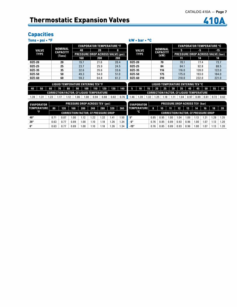
OZE-20 70 70 .1 77 .4 73 .7OZE-25 84 84 .1 92 .8 88 .5OZE-35 116 116 .0 128 .0 122 .0OZE-50 175 175 .0 193 .0 184 .0OZE-60 210 210 .0 232 .0 221 .0
VALVETYPE
NOMINAL CAPACITY
(Tons)
EVAPORATOR TEMPERATURE °F40 20 0
PRESSURE DROP ACROSS VALVE (psi)160 200 200
OZE-20 20 19 .7 21 .6 20 .4OZE-25 25 23 .7 25 .9 24 .5OZE-35 35 32 .6 35 .6 33 .6OZE-50 50 49 .3 54 .0 51 .0OZE-60 60 59 .2 64 .8 61 .2
Capacities Tons n psi n °F kW n bar n °C
LIQUID TEMPERATURE ENTERING TEV °F40 50 60 70 80 90 100 110 120 130 140
CORRECTION FACTOR, CF LIQUID TEMPERATURE1 .39 1 .31 1 .23 1 .17 1 .12 1 .06 1 .00 0 .94 0 .88 0 .82 0 .76
LIQUID TEMPERATURE ENTERING TEV °C5 10 15 20 25 30 35 40 45 50 55 60
CORRECTION FACTOR, CF LIQUID TEMPERATURE1 .46 1 .39 1 .32 1 .25 1 .18 1 .11 1 .04 0 .97 0 .89 0 .81 0 .72 0 .62
EVAPORATORTEMPERATURE
°F
PRESSURE DROP ACROSS TEV (psi)
80 120 160 200 240 280 320 360
CORRECTION FACTOR, CF PRESSURE DROP
40° 0 .71 0 .87 1 .00 1 .12 1 .22 1 .32 1 .41 1 .5020° 0 .63 0 .77 0 .89 1 .00 1 .10 1 .18 1 .26 1 .340° 0 .63 0 .77 0 .89 1 .00 1 .10 1 .18 1 .26 1 .34
EVAPORATORTEMPERATURE
°C
PRESSURE DROP ACROSS TEV (bar)
8 10 11 12 13 14 16 18 20
CORRECTION FACTOR, CF PRESSURE DROP
5° 0 .85 0 .95 1 .00 1 .04 1 .09 1 .13 1 .21 1 .28 1 .35-5° 0 .76 0 .85 0 .89 0 .93 0 .96 1 .00 1 .07 1 .13 1 .20-15° 0 .76 0 .85 0 .89 0 .93 0 .96 1 .00 1 .07 1 .13 1 .20

Page 8 — CATALOG 410A
410A Thermostatic Expansion Valves
Type EBQE & SBQEBalanced Port Replaceable Cartridge StyleKnife Edge JointStandard Cap Tube Length 5 Feet (1.5 m)
FITTING SIZE*Inches
Inches mmA B A B
3/8 2 .50 – 64 –1/2 2 .42 2 .48 61 635/8 – 2 .48 – 637/8 – 2 .39 – 61
Dimensions Type EBQE with Number 45 Element
60°
1.87”47 mmTop View
THERMOSTATICCHARGE
Inches mmC D C D
ZCP180 0 .50 3 .00 13 76ZGA 0 .75 2 .00 19 51
Bulb Sizes
Connections
Type SBQE
A B
1.94”49 mm
C
D2.02”
51 mm
3.93”100 mm
2.53”64 mm
Cap Tube5’
1.5 m
3/8 ODFInsert Strainer
P/N 877-003
1/2 ODFInsert Strainer
P/N 877-004
2.53”64 mm
.84”21mm
1.94”49 mm
C
D
3.93”100 mm
1.39”35 mm
2.48”63 mm
2.02”51 mm
Cap Tube5’
1.5 m
RemovableStrainer
P/N 3427-000
Type SBQE with Number 45 Element
60°
1.87”47 mmTop View
THERMOSTATICCHARGE
Inches mmC D C D
ZCP180 0 .50 3 .00 13 76ZGA 0 .75 2 .00 19 51
Bulb Sizes
Type EBQESporlan Types SBQE & EBQE are small brass bar body valves with extended ODF solder connections and the same balanced port construction as the Type BF valve. Both valves have replaceable thermostatic elements. The Type EBQE has a 100 mesh insert strainer. The Type SBQE has a 100 mesh removable strainer that can be cleaned and/or replaced while the valve is still soldered to
the system tubing. The balanced port construction makes these valves ideally suited for R-410A applications with varying pressure drop across the valve. The EBQE and SBQE may also be applied in bi-directional applications.
ConnectionsOnly available with 3/8” ODF Inlet and 1/2” ODF Outlet.
* Not all fitting combinations are available.

CATALOG 410A — Page 9
Thermostatic Expansion Valves 410A
CARTRIDGE TYPE
NOMINAL CAPACITY
(kW)
EVAPORATOR TEMPERATURE °C5 -5 -15
PRESSURE DROP ACROSS VALVE (bar)11 14 14
AAA 1.47 1 .47 1 .62 1 .46AA 3.15 3 .15 3 .48 3 .14A 6.72 6 .72 7 .42 6 .69B 11.8 11 .8 13 .0 11 .7C 21.8 21 .8 24 .1 21 .7
CARTRIDGE TYPE
NOMINAL CAPACITY
(Tons)
EVAPORATOR TEMPERATURE °F40 20 0
PRESSURE DROP ACROSS VALVE (psi)160 200 200
AAA 1/3 0 .419 0 .458 0 .4AA 2/3 0 .899 0 .981 0 .857A 1-1/2 1 .92 2 .09 1 .83B 3 3 .36 3 .66 3 .20C 5-1/2 6 .23 6 .80 5 .94
Capacities Tons n psi n °F kW n bar n °C
LIQUID TEMPERATURE ENTERING TEV °F40 50 60 70 80 90 100 110 120 130 140
CORRECTION FACTOR, CF LIQUID TEMPERATURE1 .39 1 .31 1 .23 1 .17 1 .12 1 .06 1 .00 0 .94 0 .88 0 .82 0 .76
LIQUID TEMPERATURE ENTERING TEV °C5 10 15 20 25 30 35 40 45 50 55 60
CORRECTION FACTOR, CF LIQUID TEMPERATURE1 .46 1 .39 1 .32 1 .25 1 .18 1 .11 1 .04 0 .97 0 .89 0 .81 0 .72 0 .62
TYPE EBQE TYPE SBQE
CARTRIDGECODE
(Port Size)
NOMINALCAPACITY
RANGE
CONNECTIONS - Inches
BOLD figures are standardand will be furnished
unless otherwise specified.
EXTENDEDODF SOLDER
EXTENDEDODF SOLDER
(with replaceable strainer)
EXTERNAL EQUALIZER TONS kW INLET X OUTLET EXTERNAL EQUALIZER
EBQE-AAA SBQE-AAA AAA 1/4 .– .1/3 0 .88 .– .1 .17 EBQE3/8 x 1/2 ODF1/2 .x .5/8 .ODF1/2 .x .7/8 .ODFStraight .Thru
SBQE3/8 x 1/2 ODF
90° .Angle .Inlet
1/4” .ODFPointed .Toward
Bottom .Cap
EBQE-AA SBQE-AA AA 1/2 .– .3/4 1 .76 .– .2 .64
EBQE-A SBQE-A A 1 .– .1-3/4 3 .52 .– .6 .15
EBQE-B SBQE-B B 2 .– .3-1/2 7 .03 .– .12 .3
EBQE-C SBQE-C C 4 .– .6 14 .1 .– .21 .1
Specifications
EVAPORATORTEMPERATURE
°F
PRESSURE DROP ACROSS TEV (psi)
80 120 160 200 240 280 320 360
CORRECTION FACTOR, CF PRESSURE DROP
40° 0 .71 0 .87 1 .00 1 .12 1 .22 1 .32 1 .41 1 .5020° 0 .63 0 .77 0 .89 1 .00 1 .10 1 .18 1 .26 1 .340° 0 .63 0 .77 0 .89 1 .00 1 .10 1 .18 1 .26 1 .34
EVAPORATORTEMPERATURE
°C
PRESSURE DROP ACROSS TEV (bar)
8 10 11 12 13 14 16 18 20
CORRECTION FACTOR, CF PRESSURE DROP
5° 0 .85 0 .95 1 .00 1 .04 1 .09 1 .13 1 .21 1 .28 1 .35-5° 0 .76 0 .85 0 .89 0 .93 0 .96 1 .00 1 .07 1 .13 1 .20-15° 0 .76 0 .85 0 .89 0 .93 0 .96 1 .00 1 .07 1 .13 1 .20
Page 10 — CATALOG 410A
410A Distributors and Auxiliary Side Connectors
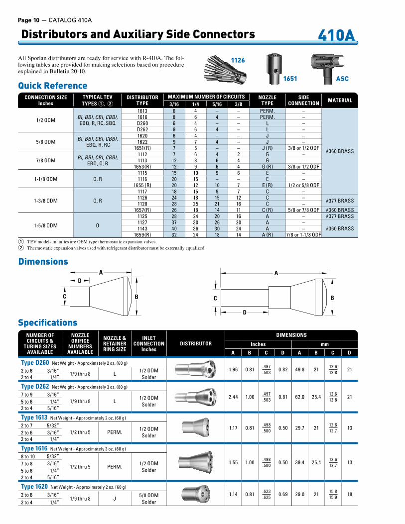
All Sporlan distributors are ready for service with R-410A. The fol-lowing tables are provided for making selections based on procedure explained in Bulletin 20-10.
Quick Reference
1126
1651 ASC
CONNECTION SIZEInches
TYPICAL TEVTYPES Q, W
DISTRIBUTORTYPE
MAXIMUM NUMBER OF CIRCUITS NOZZLETYPE
SIDECONNECTION MATERIAL
3/16 1/4 5/16 3/8
1/2 .ODM BI, BBI, CBI, CBBI,EBQ, .R, .RC, .SBQ .
1613 6 4 – – PERM . –
#360 .BRASS
1616 8 6 4 – PERM . –D260 6 4 – – L –D262 9 6 4 – L –
5/8 .ODM BI, BBI, CBI, CBBI, .EBQ, .R, .RC
1620 6 4 – – J –1622 9 7 4 – J –
1651(R) 7 5 – – J .(R) 3/8 .or .1/2 .ODF
7/8 .ODM BI, BBI, CBI, CBBI,EBQ, .O, .R
1112 7 6 4 2 G –1113 12 8 6 4 G –
1653(R) 12 9 6 4 G .(R) 3/8 .or .1/2 .ODF
1-1/8 .ODM O, .R1115 15 10 9 6 E –1116 20 15 – – E –
1655 .(R) 20 12 10 7 E .(R) 1/2 .or .5/8 .ODF
1-3/8 .ODM O, .R
1117 18 15 9 7 C –1126 24 18 15 12 C – #377 .BRASS1128 28 25 21 16 C –
1657(R) 26 18 14 11 C .(R) 5/8 .or .7/8 .ODF #360 .BRASS
1-5/8 .ODM O
1125 28 24 20 16 A – #377 .BRASS1127 37 30 26 20 A –
#360 .BRASS1143 40 36 30 24 A –1659(R) 32 24 18 14 A .(R) 7/8 .or .1-1/8 .ODF
AD
C B
DimensionsA
D
BC
Q TEV models in italics are OEM type thermostatic expansion valves.W Thermostatic expansion valves used with refrigerant distributor must be externally equalized.
SpecificationsNUMBER OFCIRCUITS &
TUBING SIZESAVAILABLE
NOZZLEORIFICE
NUMBERSAVAILABLE
NOZZLE & RETAINERRING SIZE
INLETCONNECTION
InchesDISTRIBUTOR
DIMENSIONS
Inches mm
A B C D A B C D
Type D260 Net .Weight .- .Approximately .2 .oz . .(60 .g)1 .96 0 .81 .497
.503 0 .82 49 .8 21 12 .612 .8 212 .to .6 3/16” 1/9 .thru .8 L
1/2 .ODMSolder2 .to .4 . 1/4”
Type D262 Net .Weight .- .Approximately .3 .oz . .(80 .g)
2 .44 1 .00 .497 .503 0 .81 62 .0 25 .4 12 .6
12 .8 217 .to .9 3/16”1/9 .thru .8 L
1/2 .ODMSolder5 .to .6 1/4”
2 .to .4 5/16”
Type 1613 Net .Weight .- .Approximately .2 .oz . .(60 .g)
1 .17 0 .81 .498 .500 0 .50 29 .7 21 12 .6
12 .7 132 .to .7 5/32”1/2 .thru .5 PERM .
1/2 .ODMSolder2 .to .6 3/16”
2 .to .4 1/4”
Type 1616 Net .Weight .- .Approximately .3 .oz . .(80 .g)
1 .55 1 .00 .498 .500 0 .50 39 .4 25 .4 12 .6
12 .7 138 .to .10 5/32”
1/2 .thru .5 PERM .1/2 .ODMSolder
7 .to .8 3/16”5 .to .6 1/4”2 .to .4 5/16”
Type 1620 Net .Weight .- .Approximately .2 .oz . .(60 .g)
1 .14 0 .81 .623 .625 0 .69 29 .0 21 15 .8
15 .9 182 .to .6 3/16”1/9 .thru .8 J
5/8 .ODMSolder2 .to .4 1/4”
CATALOG 410A — Page 11
410A Distributors and Auxiliary Side Connectors
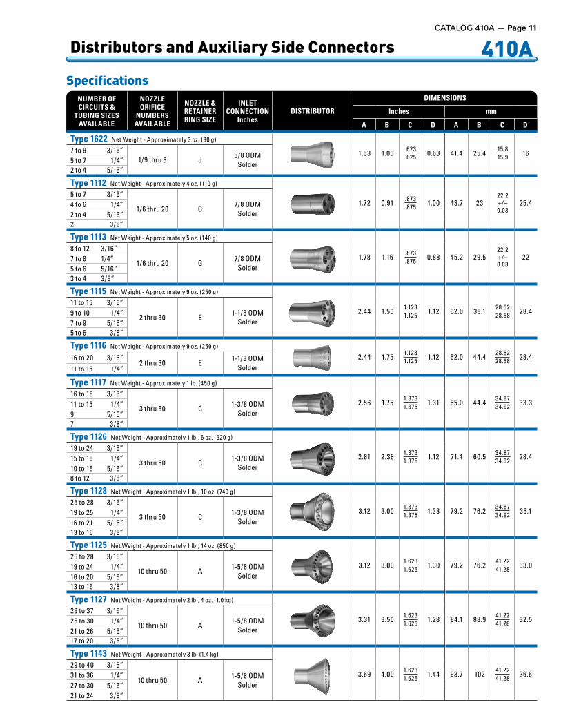
SpecificationsNUMBER OFCIRCUITS &
TUBING SIZESAVAILABLE
NOZZLEORIFICE
NUMBERSAVAILABLE
NOZZLE & RETAINERRING SIZE
INLETCONNECTION
InchesDISTRIBUTOR
DIMENSIONS
Inches mm
A B C D A B C D
Type 1622 Net .Weight .- .Approximately .3 .oz . .(80 .g)
1 .63 1 .00 .623 .625 0 .63 41 .4 25 .4 15 .8
15 .9 167 .to .9 3/16”1/9 .thru .8 J
5/8 .ODMSolder5 .to .7 1/4”
2 .to .4 5/16”
Type 1112 Net .Weight .- .Approximately .4 .oz . .(110 .g)
1 .72 0 .91 .873 .875 1 .00 43 .7 23
22 .2+/–0 .03
25 .45 .to .7 3/16”
1/6 .thru .20 G7/8 .ODM
Solder4 .to .6 1/4”2 .to .4 5/16”2 3/8”
Type 1113 Net .Weight .- .Approximately .5 .oz . .(140 .g)
1 .78 1 .16 .873 .875 0 .88 45 .2 29 .5
22 .2+/–0 .03
228 .to .12 3/16”
1/6 .thru .20 G7/8 .ODM
Solder7 .to .8 1/4”5 .to .6 5/16”3 .to .4 . 3/8”
Type 1115 Net .Weight .- .Approximately .9 .oz . .(250 .g)
2 .44 1 .50 1 .1231 .125 1 .12 62 .0 38 .1 28 .52
28 .58 28 .411 .to .15 3/16”
2 .thru .30 E1-1/8 .ODM
Solder9 .to .10 1/4”7 .to .9 5/16”5 .to .6 3/8”
Type 1116 Net .Weight .- .Approximately .9 .oz . .(250 .g)
2 .44 1 .75 1 .1231 .125 1 .12 62 .0 44 .4 28 .52
28 .58 28 .416 .to .20 3/16”2 .thru .30 E
1-1/8 .ODMSolder11 .to .15 1/4”
Type 1117 Net .Weight .- .Approximately .1 .lb . .(450 .g)
2 .56 1 .75 1 .3731 .375 1 .31 65 .0 44 .4 34 .87
34 .92 33 .316 .to .18 3/16”
3 .thru .50 C1-3/8 .ODM
Solder11 .to .15 1/4”9 5/16”7 3/8”
Type 1126 Net .Weight .- .Approximately .1 .lb ., .6 .oz . .(620 .g)
2 .81 2 .38 1 .3731 .375 1 .12 71 .4 60 .5 34 .87
34 .92 28 .419 .to .24 3/16”
3 .thru .50 C1-3/8 .ODM
Solder15 .to .18 1/4”10 .to .15 5/16”8 .to .12 3/8”
Type 1128 Net .Weight .- .Approximately .1 .lb ., .10 .oz . .(740 .g)
3 .12 3 .00 1 .3731 .375 1 .38 79 .2 76 .2 34 .87
34 .92 35 .125 .to .28 3/16”
3 .thru .50 C1-3/8 .ODM
Solder19 .to .25 1/4”16 .to .21 5/16”13 .to .16 3/8”
Type 1125 Net .Weight .- .Approximately .1 .lb ., .14 .oz . .(850 .g)
3 .12 3 .00 1 .6231 .625 1 .30 79 .2 76 .2 41 .22
41 .28 33 .025 .to .28 3/16”
10 .thru .50 A1-5/8 .ODM
Solder19 .to .24 1/4”16 .to .20 5/16”13 .to .16 3/8”
Type 1127 Net .Weight .- .Approximately .2 .lb ., .4 .oz . .(1 .0 .kg)
3 .31 3 .50 1 .6231 .625 1 .28 84 .1 88 .9 41 .22
41 .28 32 .529 .to .37 3/16”
10 .thru .50 A1-5/8 .ODM
Solder25 .to .30 1/4”21 .to .26 5/16”17 .to .20 3/8”
Type 1143 Net .Weight .- .Approximately .3 .lb . .(1 .4 .kg)
3 .69 4 .00 1 .6231 .625 1 .44 93 .7 102 41 .22
41 .28 36 .629 .to .40 3/16”
10 .thru .50 A1-5/8 .ODM
Solder31 .to .36 1/4”27 .to .30 5/16”21 .to .24 3/8”

Page 12 — CATALOG 410A
Distributors and Auxiliary Side Connectors 410A
NOZZLENUMBER
DISTRIBUTOR NOZZLE CAPACITIESEVAPORATOR TEMPERATURE °F
40 20 0 -20 -401/9 0 .16 0 .13 0 .10 0 .08 0 .071/6 0 .25 0 .20 0 .16 0 .13 0 .111/4 0 .40 0 .31 0 .25 0 .21 0 .171/3 0 .53 0 .41 0 .33 0 .27 0 .231/2 0 .73 0 .57 0 .46 0 .37 0 .313/4 1 .10 0 .86 0 .69 0 .57 0 .471 1 .47 1 .15 0 .92 0 .76 0 .64
1-1/2 2 .14 1 .67 1 .34 1 .10 0 .922 2 .93 2 .30 1 .84 1 .51 1 .27
2-1/2 3 .66 2 .86 2 .30 1 .88 1 .583 4 .39 3 .44 2 .76 2 .26 1 .904 5 .88 4 .60 3 .69 3 .02 2 .545 7 .25 5 .67 4 .55 3 .73 3 .136 8 .69 6 .80 5 .45 4 .47 3 .768 10 .5 8 .19 6 .57 5 .39 4 .53
10 11 .7 9 .18 7 .36 6 .04 5 .0712 14 .5 11 .3 9 .09 7 .46 6 .2615 18 .0 14 .1 11 .3 9 .25 7 .7717 20 .1 15 .7 12 .6 10 .3 8 .6920 24 .2 19 .0 15 .2 12 .5 10 .525 30 .5 23 .8 19 .1 15 .7 13 .230 34 .8 27 .2 21 .8 17 .9 15 .035 41 .9 32 .8 26 .3 21 .5 18 .140 47 .0 36 .8 29 .5 24 .2 20 .350 60 .9 47 .7 38 .2 31 .3 26 .3
Capacities Tons n psi n °F kW n bar n °C
LIQUID TEMPERATURE CORRECTION FOR NOZZLE AND TUBES °F50 60 70 80 90 100 110 120 130 140
CORRECTION FACTOR, CF LIQUID TEMPERATURE2 .10 1 .83 1 .59 1 .37 1 .17 1 .00 0 .85 0 .72 0 .61 0 .52
LIQUID TEMPERATURE CORRECTION FOR NOZZLE AND TUBES °C10 15 20 25 30 35 38 40 45 50 55 60
CORRECTION FACTOR, CF LIQUID TEMPERATURE2 .10 1 .86 1 .64 1 .44 1 .25 1 .09 1 .00 0 .94 0 .81 0 .70 0 .60 0 .52
TUBE LENGTH CORRECTION FACTOR (Inches)12 18 24 30 36 42 48 54 60 66 72
CORRECTION FACTOR, CF PRESSURE DROP1 .36 1 .16 1 .07 1 .00 0 .95 0 .90 0 .86 0 .82 0 .79 0 .76 0 .73
NOZZLENUMBER
DISTRIBUTOR NOZZLE CAPACITIESEVAPORATOR TEMPERATURE °C
5 -5 -15 -30 -401/9 0 .57 0 .46 0 .37 0 .29 0 .241/6 0 .88 0 .71 0 .58 0 .44 0 .381/4 1 .42 1 .14 0 .93 0 .71 0 .611/3 1 .86 1 .49 1 .22 0 .93 0 .801/2 2 .57 2 .06 1 .68 1 .29 1 .103/4 3 .88 3 .11 2 .54 1 .94 1 .661 5 .20 4 .16 3 .40 2 .60 2 .22
1-1/2 7 .56 6 .06 4 .95 3 .78 3 .232 10 .4 8 .31 6 .79 5 .18 4 .44
2-1/2 12 .9 10 .4 8 .47 6 .46 5 .533 15 .5 12 .4 10 .2 7 .76 6 .644 20 .8 16 .7 13 .6 10 .4 8 .895 25 .7 20 .5 16 .8 12 .8 11 .06 30 .8 24 .6 20 .1 15 .4 13 .18 37 .1 29 .7 24 .2 18 .5 15 .8
10 41 .5 33 .3 27 .2 20 .7 17 .712 51 .3 41 .1 33 .5 25 .6 21 .915 63 .6 50 .9 41 .6 31 .8 27 .217 71 .1 57 .0 46 .5 35 .5 30 .420 85 .7 68 .6 56 .1 42 .8 36 .625 108 86 .3 70 .5 53 .8 46 .130 123 98 .6 80 .6 61 .5 52 .635 148 119 96 .9 74 .0 63 .340 166 133 109 83 .0 71 .050 216 173 141 108 92 .1
TUBE LENGTH CORRECTION FACTOR (cm)30 45 60 75 90 105 120 135 150 165 180
CORRECTION FACTOR, CF PRESSURE DROP1 .36 1 .16 1 .07 1 .00 0 .95 0 .90 0 .86 0 .82 0 .79 0 .76 0 .73
TUBEDIAMETER
Inches
DISTRIBUTOR CAPACITY PER TUBE (Tons)EVAPORATOR TEMPERATURE °F
40 20 0 -20 -403/16 0 .41 0 .31 0 .23 0 .18 0 .141/4 1 .19 0 .89 0 .68 0 .52 0 .40
5/16 2 .41 1 .82 1 .38 1 .06 0 .823/8 4 .33 3 .28 2 .50 1 .92 1 .48
TUBEDIAMETER
Inches
DISTRIBUTOR CAPACITY PER TUBE (kW)EVAPORATOR TEMPERATURE °C
5 -5 -15 -30 -403/16 1 .47 1 .13 0 .88 0 .61 0 .481/4 4 .28 3 .28 2 .55 1 .77 1 .40
5/16 8 .72 6 .69 5 .20 3 .60 2 .853/8 15 .8 . 12 .1 9 .40 6 .51 5 .15
For proper distributor type, order by complete Sporlan type listed below. E.g., an 1126 distributor requires an ASC-11-7 Auxiliary Side Connector. Do not use an ASC that is smaller or larger than recommended. Bushing up or down at the outlet defeats the purpose of the internal nozzle tube extension. Do not use an ASC on distributors with permanent nozzles.
TYPE
CONNECTION SIZES - InchesUSED WITH
DISTRIBUTORTYPE
NOZZLESIZE
DIMENSIONS
INLETODM
SOLDER
OUTLETODF
SOLDER
AUXILIARYODF
SOLDER
Inches mm
A (ODM)
B(ODF) C D E F
(ODF)A
(ODM)B
(ODF) C D E F(ODF)
ASC-4-3 1/2 1/2 3/8 D260, .D262 L 1/2 . 1/2 1 .75 0 .85 1 .04 3/8 12 .7 12 .7 44 .4 22 26 .4 9 .52ASC-5-4 5/8 5/8 1/2 1620, .1622 J 5/8 . 5/8 1 .88 0 .95 1 .25 1/2 15 .9 15 .9 47 .8 24 31 .8 12 .7ASC-7-4 7/8 7/8 1/2 1112, .1113 G 7/8 . 7/8 2 .25 1 .06 1 .38 1/2 22 .2 22 .2 51 .2 26 .9 35 .1 12 .7ASC-9-5 1-1/8 1-1/8 5/8 1115, .1116 E 1-1/8 . 1-1/8 2 .81 1 .47 1 .62 5/8 28 .6 28 .6 71 .4 37 .3 41 .1 15 .9ASC-11-7 1-3/8 1-3/8 7/8 1117, .1126, .1128 C 1-3/8 . 1-3/8 3 .53 1 .89 2 .19 7/8 34 .9 34 .9 89 .7 48 .0 55 .6 22 .2ASC-13-9 1-5/8 1-5/8 1-1/8 1125, .1127, .1143 A 1-5/8 1-5/8 3 .85 1 .95 2 .75 1-1/8 41 .3 41 .3 94 .5 46 .5 69 .8 28 .6
Auxiliary Side ConnectorsASC-4-3, ASC-5-4, ASC-7-4, ASC-9-5, ASC-11-7, and ASC-13-9
C
DF
BOutlet
AInlet
E AuxiliaryConnection
CATALOG 410A — Page 13
410A Selection - Capacity Rating
Solenoid Valves
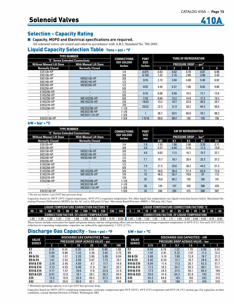
n Capacity, MOPDandElectricalspecificationsarerequired. All solenoid valves are tested and rated in accordance with A.R.I. Standard No. 760-2001.
* Do not use below 1 psi (0.07 bar) pressure drop.
Capacities based on 100°F (38°C) liquid temperature, 40°F (5°C) evaporator temperature. For other liquid line temperatures use liquid correction factors below. Maximum Op-erating Pressure Differential (MOPD) for the AC coil is 450 psid (31 bar). Maximum Rated Pressure (MRP) = 700 psig (48.3 bar).
LIQUID TEMPERATURE CORRECTION FACTORS °F40 50 60 70 80 90 100 110 120 130 140
CORRECTION FACTOR, CF LIQUID TEMPERATURE1 .45 1 .38 1 .30 1 .23 1 .15 1 .08 1 .00 0 .92 0 .83 0 .74 0 .64
LIQUID TEMPERATURE CORRECTION FACTORS °C5 10 15 20 25 30 35 40 45 50 55 60
CORRECTION FACTOR, CF LIQUID TEMPERATURE1 .45 1 .38 1 .32 1 .25 1 .18 1 .11 1 .04 0 .97 0 .90 0 .82 0 .74 0 .64
These factors include corrections for liquid refrigerant density and net refrigerating effect and are based on an average evaporator temperature of 40°F (5°C). For each 10°F (10°C) reduction in evaporating temperature, capacities are reduced by approximately 1-1/2% (2.7%).
* Minimum operating capacity is at 1 psi (0.07 bar) pressure drop.
Capacities based on 100°F (38°C) condensing temperature, isentropic compression plus 50°F (28°C), 40°F (5°C) evaporator and 65°F (18.3°C) suction gas. For capacities at other conditions, consult Sporlan Division of Parker, Washington, MO.
Discharge Gas Capacity - Tons n psi n °F kW n bar n °C
VALVESERIES
DISCHARGE GAS CAPACITIES – TonsPRESSURE DROP ACROSS VALVE – psi
2 5 10 25 50 100E2 . .0 .15 0 .24 0 .35 0 .55 0 .86 1 .08E5 0 .54 0 .86 1 .22 2 .26 3 .02 3 .75B6 & E6 1 .00 1 .57 2 .20 3 .86 5 .06 6 .04B9 & E9 1 .61 2 .54 3 .58 5 .67 7 .72 10 .1B10 & E10 2 .19 3 .46 4 .89 8 .7 11 .7 14 .6B14 & E14 3 .13 4 .93 6 .96 11 .9 16 .1 20 .7B19 & E19 4 .71 7 .47 10 .6 17 .6 23 .9 31 .0B25 & E25 8 .07 12 .8 18 .1 28 .1 38 .2 49 .5E35 12 .0 19 .8 28 .9 49 .3 67 .3 88 .5E42 25 .1 39 .6 56 .0 82 .1 111 144
VALVESERIES
DISCHARGE GAS CAPACITIES – kW PRESSURE DROP ACROSS VALVE – bar
0.15 0.3 0.7 1.5 4 7E2 0 .54 0 .79 1 .22 1 .78 3 .09 3 .50E5 1 .97 2 .81 4 .32 7 .47 11 .2 13 .2B6 & E6 3 .66 5 .14 7 .80 12 .8 18 .7 21 .3B9 & E9 5 .92 8 .34 12 .7 18 .7 28 .9 35 .7B10 & E10 8 .04 11 .4 17 .3 28 .7 43 .3 51 .7B14 & E14 11 .5 16 .2 24 .7 39 .3 60 .1 73 .1B19 & E19 17 .3 24 .5 37 .5 58 .1 89 .4 109B25 & E25 29 .6 41 .9 64 .2 92 .8 143 175E35 44 .3 64 .6 103 162 252 313E42 91 .9 130 198 271 416 510
TYPE NUMBERCONNECTIONS
ODF SOLDERInches
PORTSIZE
Inches
TONS OF REFRIGERATION“E” Series Extended Connections
Without Manual Lift Stem With Manual Lift Stem PRESSURE DROP — psi*Normally Closed Normally Closed 1 2 3 4 5
E2S120-HP – 1/4 0 .075 0 .43 0 .62 0 .76 0 .87 0 .98E5S130-HP – 3/8 0 .150 1 .52 2 .16 2 .66 3 .08 3 .45E6S130-HP ME6S130-HP 3/8 3/16 2 .73 3 .84 4 .68 5 .40 6 .02E6S140-HP ME6S140-HP 1/2E9S240-HP ME9S240-HP 1/2 9/32 4 .44 6 .27 7 .66 8 .83 9 .86E9S250-HP – 5/8E10S240-HP – 1/2 5/16 6 .08 8 .59 10 .5 12 .1 13 .6E10S250-HP – 5/8E14S250-HP ME14S250-HP 5/8 7/16 8 .64 12 .2 14 .9 17 .2 19 .2E19S270-HP ME19S270-HP 7/8 19/32 13 .2 18 .7 22 .9 26 .5 29 .7E25S270-HP – 7/8 25/32 22 .5 31 .9 39 .2 45 .3 50 .6E25S290-HP ME25S290-HP 1-1/8
– ME35S190-HP 1-1/8 1 36 .7 53 .5 66 .8 78 .1 88 .2– ME35S1110-HP 1-3/8E42S2130-HP – 1-5/8 1-5/16 69 .6 98 .4 120 139 156
Liquid Capacity Selection Table Tons n psi n °F
kW n bar n °CTYPE NUMBER
CONNECTIONSODF SOLDER
Inches
PORTSIZEmm
kW OF REFRIGERATION“E” Series Extended Connections
Without Manual Lift Stem With Manual Lift Stem PRESSURE DROP — bar*Normally Closed Normally Closed 0.07 0.1 0.2 0.3 0.4
E25120-HP – 1/4 1 .9 1 .53 1 .80 2 .60 3 .20 3 .71E5S130-HP – 3/8 3 .8 5 .37 6 .44 9 .16 11 .3 13 .0E6S130-HP ME6S130-HP 3/8 4 .8 9 .63 11 .5 16 .1 19 .7 22 .7E6S140-HP ME6S140-HP 1/2E9S240-HP ME9S240-HP 1/2 7 .1 15 .7 18 .7 26 .4 32 .3 37 .2E9S250-HP – 5/8E10S240-HP – 1/2 7 .9 21 .5 25 .6 36 .2 44 .3 51 .2E10S250-HP – 5/8E14S250-HP ME14S250-HP 5/8 11 39 .5 36 .4 51 .4 62 .9 72 .6E19S270-HP ME19S270-HP 7/8 15 46 .5 55 .7 79 .0 97 112E25S270-HP – 7/8 20 79 .6 95 .2 135 165 191E25S290-HP ME25S290-HP 1-1/8
– ME35S190-HP 1-1/8 26 129 157 230 286 335– ME35S1110-HP 1-3/8E42S2130-HP – 1-5/8 34 246 294 415 508 587

Page 14 — CATALOG 410A
410A Solenoid Valves
The E2 Series are hermetic solenoid valves with direct acting con-struction. These valves may be mounted horizontally, on their side or in a vertical line.
The E5 Series are hermetic solenoid valves with pilot operated disc construction. These valves may be mounted horizontally, on their side or in a vertical line.
The E5 series solenoid valves feature extended solder type connec-tions as standard. One important benefit to the user is that all valves in the “E5” series can be installed using either low or no silver content brazing alloy.
The MKC-l coil is Class “F” temperature rated and is provided as standard, therefore a high temperature coil is not required for dis-charge service.
Ordering InstructionsWhen ordering complete valves, specify Valve Type, Connections, Voltage and Cycles. When order-ing Body Assembly, specify Valve Type and Connections. When or-dering Coil Assembly ONLY, specify Coil Type, Voltage and Cycles.Example: MKC-1 120/50-60.
Type E2 and E5 Series
C
DE
B
1.56”40 mm Coil Removal
2.92”74 mm
A
Type E5S130-HP
E2 Series
VALVESERIES TYPE A B C
D E
FITTINGDEPTH
OFF
SET
ODF
Inches
E2 E2S120-HP 4 .63 0 .53 2 .01 0 .31 0 .25
E5 E5S130-HP 4 .56 0 .53 2 .51 0 .31 0 .23
mm
E2 E2S120-HP 117 .6 13 .5 51 .0 8 6 .35
E5 E5S130-HP 116 13 .5 63 .7 8 6
Dimensions
VALVESERIES TYPE
CON
NEC
TIO
NS
OD
F - I
nche
s
PORT SIZE
Inches
MOPDpsi
NOMINAL LIQUIDCAPACITIES
TONS ofREFRIGERATION
AC DC PRESSURE DROP 3 psi
E2 E2S120-HP 1/4 0 .75 450 400 0 .76
E5 E5S130-HP 3/8 0 .150 450 400 2 .66
Specifications - MKC-1 CoilTons n psi n °F kW n bar n °C
VALVESERIES TYPE
CON
NEC
TIO
NS
OD
F - I
nche
s
PORT SIZEmm
MOPDbar
NOMINAL LIQUIDCAPACITIES
kW ofREFRIGERATION
AC DC PRESSURE DROP 0.2 bar
E2 E2S120-HP 1/4 1 .9 31 27 .6 2 .60
E5 E5S130-HP 3/8 3 .8 31 27 .6 9 .16
COIL RATINGS
STANDARDVOLTS/CYCLES
WATTS
AC DC
24/50-60120/50-60
208-240/50-60120-208-240/50-60
10 15
Approved
n Maximum rated pressure 700 psi (48.3 bar).n Capacities based on 100°F (38°C) liquid temperature, 40°F (5°C) evaporator tem-
perature. For other liquid line temperatures use liquid correction factors below. Maximum Operating Pressure Differential (MOPD) for the AC coil is 450 psid (31 bar). Maximum Rated Pressure (MRP) = 700 psig (48.3 bar).
n Dual voltage 4-wire coils, 120-208-240/50-60 are available at slight additional cost. For other voltages and cycles, consult Sporlan Division of Parker, Washington, MO.
n Available with conduit boss, junction box, or DIN at no extra charge.n For capacity at other pressure drops, see page 13.

Solenoid Valves 410A
The E6 Series are compact solenoid valves with pilot operated disc construction for refrigeration and air conditioning. These valves may be mounted horizontally, on their side or in a vertical line. They are suitable for suction line service because very low pressure differ-ential, 1 psi, is required for full operation.
The Type E6 series solenoid valves feature extended solder type connections as standard. One important benefit to the user is that all valves in the “E6” series can be installed without disassembly using either low or no silver content brazing alloy.
The MKC-l coil is Class “F” tem-perature rated and is provided as standard, therefore a high tempera-ture coil is not required for discharge service.
Ordering InstructionsWhen ordering complete valves, specify Valve Type, Connections, Voltage and Cycles. When ordering Body Assembly, specify Valve Type and Connections. When ordering Coil Assembly ONLY, specify Coil Type, Voltage and Cycles. Example: MKC-1 120/50-60.
Type E6 Series
2.92”74 mm
C
D
E*B
1.56”40 mm Coil Removal
A
Type E6S130-HP
E6 Series
n Maximum rated pressure 700 psi (48.3 bar).n Capacities based on 100°F (38°C) liquid temperature, 40°F (5°C) evaporator tem-
perature. For other liquid line temperatures use liquid correction factors below. Maximum Operating Pressure Differential (MOPD) for the AC coil is 450 psid (31 bar). Maximum Rated Pressure (MRP) = 700 psig (48.3 bar).
n Dual voltage 4-wire coils, 120-208-240/50-60 are available at slight additional cost. For other voltages and cycles, consult Sporlan Division of Parker, Washington, MO.
n Available with conduit boss, junction box, or DIN at no extra charge.n For mounting holes and/or bracket information, see Bulletin 30-11n E6 series with mounting holes are NOT standard.n For capacity at other pressure drops, see page 13.
1.64”42 mm
Optional 1/2”Conduit Boss
VALVESERIES TYPE A B* C
D E
FITTINGDEPTH
OFF
SET
ODF
Inches
E6E6S130-HP 4 .63
0 .75 2 .440 .31
0 .31E6S140-HP 5 .00 0 .38
mm
E6E6S130-HP 118
19 627 .9
7 .9E6S140-HP 127 9 .7
Dimensions
VALVESERIES TYPE
CON
NEC
TIO
NS
OD
F - I
nche
s
PORT SIZE
Inches
MOPDpsi
NOMINAL LIQUIDCAPACITIES
TONS ofREFRIGERATION
AC DC PRESSURE DROP 3 psi
E6E6S130-HP
3/83/16 450 400 4 .68ME6S130-HP
ME6S140-HP 1/2
Specifications - MKC-1 CoilTons n psi n °F kW n bar n °C
VALVESERIES TYPE
CON
NEC
TIO
NS
OD
F - I
nche
s
PORT SIZEmm
MOPDbar
NOMINAL LIQUIDCAPACITIES
kW ofREFRIGERATION
AC DC PRESSURE DROP 0.2 bar
E6E6S130-HP
3/84 .8 31 27 .6 16 .1ME6S130-HP
ME6S140-HP 1/2
COIL RATINGS
STANDARDVOLTS/CYCLES
WATTS
AC DC
24/50-60120/50-60
208-240/50-60120-208-240/50-60
10 15
Approved
* Add 1.12” (28 mm) for valves with Manual Lift Stem.
CATALOG 410A — Page 15

Page 16 — CATALOG 410A
410A Solenoid Valves
Types E9, E10, E14, E19 and E25 Series are compact solenoid valves with pilot operated disc construction for refrigeration and air conditioning. These valves may be mounted horizontally, on their side or in a vertical line. These valves are also suitable for suction line service because very low pressure differential, 1 psi, is required for full operation.
The E9, E10, E14, E19 and E25 series solenoid valves feature extended solder type connections as standard. One important benefit to the user is that all valves in the “E9, E10, E14, E19 and E25” series can be installed without disassembly using either low or no silver content brazing alloy.
The MKC-2 and OMKC-2 coils are Class “F” temperature rated and are provided as standard, therefore a high temperature coil is not required for discharge service.
Ordering InstructionsWhen ordering complete valves, specify Valve Type, Connections, Voltage and Cycles. When ordering Body Assembly, specify Valve Type and Connections. When ordering Coil Assembly ONLY, spec-ify Coil Type, Voltage and Cycles. Example: MKC-2 120/50-60; OMKC-2 120/50-60.
Types E9, E10, E14, E19 and E25 Series
VALVESERIES TYPE A *B
C D E
NO
RMA
LLY
CLO
SED
FITT
ING
DEP
TH
OFF
SET
ODF
Inches
E9E9S230-HP 4 .63 0 .69 2 .65 0 .31 0 .39E9S240-HP 5 .00 0 .75 2 .70 0 .38 0 .33E9S250-HP 6 .50 0 .69 2 .74 0 .50 0 .31
E10E10S240-HP 5 .00 0 .85 3 .13 0 .38 0 .38E10S250-HP 6 .50 0 .85 3 .13 0 .50 0 .38
E14 E14S250-HP 6 .88 0 .46 3 .26 0 .50 –E19 E19S270-HP 7 .13 0 .81 3 .41 0 .75 –
E25E25S270-HP 7 .50 0 .72 3 .81 0 .75 –E25S290-HP 8 .50 0 .72 3 .81 0 .91 –
mm
E9E9S230-HP 118 18 .0 67 7 .9 9 .9E9S240-HP 127 9 .7 69 9 .7 7 .9E9S250-HP 165 12 .7 69 13 .0 9 .7
E10E10S240-HP 127 9 .7 80 9 .7 9 .7E10S250-HP 165 9 .7 80 13 .0 9 .7
E14 E14S250-HP 175 11 .7 83 13 .0 –E19 E19S270-HP 181 21 .0 87 19 .0 –
E25E25S270-HP 191 18 .0 97 19 .0 –E25S290-HP 216 18 .0 97 23 .0 –
Dimensions
A
1.75”44 mm Coil Removal
3.17”81 mm
D
C
*BE
Type E14S250-HP
E10 Series
VALV
ESE
RIES
TYPE
CON
NEC
TIO
NS
OD
F - I
nche
s
PORT SIZE
Inches
MOPDpsi
NOMINAL LIQUIDCAPACITIES
TONS ofREFRIGERATION
AC DC PRESSURE DROP 3 psi
E9E9S230-HP 3/8
9/32
450 400
7 .66E9 .& .ME9S240-HP 1/2E9S250-HP 5/8
E10E10 .& .ME10S240-HP 1/2
5/16 10 .5E10 .& .ME10S250-HP 5/8
E14 E14 .& .ME14S250-HP 5/8 7/16 14 .9E19 E19 .& .ME19S270-HP 7/8 19/32 22 .9
E25E25 .& .ME25S270-HP 7/8
25/32 39 .2E25 .& .ME25S290-HP 1-1/8
Specifications - MKC-2 and OMKC-2 CoilTons n psi n °F kW n bar n °C
n Maximum rated pressure 700 psi (48.3 bar).n Capacities based on 100°F (38°C) liquid temperature, 40°F (5°C) evaporator tem-
perature. For other liquid line temperatures use liquid correction factors below. Maximum Operating Pressure Differential (MOPD) for the AC coil is 450 psid (31 bar). Maximum Rated Pressure (MRP) = 700 psig (48.3 bar).
n Dual voltage 4-wire coils, 120-208-240/50-60 are available at slight additional cost. For other voltages and cycles, consult Sporlan Division of Parker, Washington, MO.
n Available with conduit boss, junction box, or DIN at no extra charge.n For capacity at other pressure drops, see page 13.
1.89”48 mm
Optional 1/2”Conduit Boss
COIL RATINGS
STANDARDVOLTS/CYCLES
WATTS
AC DC
24/50-60120/50-60
208-240/50-60120-208-240/50-60
15 18
VALV
ESE
RIES
TYPE
CON
NEC
TIO
NS
OD
F - I
nche
s
PORT SIZEmm
MOPDbar
NOMINAL LIQUIDCAPACITIES
kW ofREFRIGERATION
AC DC PRESSURE DROP0.2 bar
E9E9S230-HP 3/8
7 .1
31 27 .6
32 .3E9 .& .ME9S240-HP 1/2E9S250-HP 5/8
E10E10 .& .ME10S240-HP 1/2
7 .9 44 .3E10 .& .ME10S250-HP 5/8
E14 E14 .& .ME14S250-HP 5/8 11 62 .9E19 E19 .& .ME19S270-HP 7/8 15 97 .0
E25E25 .& .ME25S270-HP 7/8
20 165E25 .& .ME25S290-HP 1-1/8
Approved
* Add 1.12” (28 mm) for valves with Manual Lift Stem.
Listed

CATALOG 410A — Page 17
410A Solenoid Valves
Types E35 Series
VALVESERIES TYPE A B
C D *E
NO
RMA
LLY
CLO
SED
NO
RMA
LLY
OPE
N
FITT
ING
DEP
TH
OFF
SET
ODF
Inches
E35E35S190-HP 10 .06 5 .03
4 .81 5 .940 .91 0 .84
E35S1110-HP 11 .06 5 .53 0 .97 0 .84
mm
E35E35S190-HP 256 128
122 15123 21
E35S1110-HP 281 140 25 21
Dimensions
C
DE
D
1.56”40 mm Coil Removal
AB B
ME35 Series
VALVESERIES TYPE
CON
NEC
TIO
NS
OD
F - I
nche
s
PORT SIZE
Inches
MOPDpsi
NOMINAL LIQUIDCAPACITIES
TONS ofREFRIGERATION
AC DC PRESSURE DROP 3 psi
E35ME35S190-HP 1-1/8
1 450 400 66 .7ME35S1110-HP Q1-3/8
Specifications - MKC-1 and OMKC-1 CoilTons n psi n °F kW n bar n °C
n Maximum rated pressure 700 psi (48.3 bar).n Capacities based on 100°F (38°C) liquid temperature, 40°F (5°C) evaporator tem-
perature. For other liquid line temperatures use liquid correction factors below. Maximum Operating Pressure Differential (MOPD) for the AC coil is 450 psid (31 bar). Maximum Rated Pressure (MRP) = 700 psig (48.3 bar).
n Dual voltage 4-wire coils, 120-208-240/50-60 are available at slight additional cost. For other voltages and cycles, consult Sporlan Division of Parker, Washington, MO.
n Available with conduit boss, junction box, or DIN at no extra charge.n For capacity at other pressure drops, see page 13.
1.64”42 mm
Optional 1/2”Conduit Boss
Approved
* Add 1.12” (28 mm) for valves with Manual Lift Stem.
Types E35 Series solenoid valves are pilot operated for refrigeration and air conditioning applications. They are suitable for suction ser-vice because very low pressure differential, 1 psi, is required for full operation. The E35 Series may be mounted horizontally, on their side or in a vertical line.
The Type E35 series solenoid valves feature extended solder type connections as standard. One important benefit to the user is that all valves in the “E35” series can be installed without disassembly using either low or no silver content brazing alloy.
The MKC-1 and OMKC-1 coils are Class “F” temperature rated and are provided as standard, therefore a high temperature coil is not required for discharge service.
Ordering InstructionsWhen ordering complete valves, specify Valve Type, Connections, Voltage and Cycles. When ordering Body Assembly, specify Valve Type and Connections.
Q 1-5/8” ODM Type L tubing may be slipped over 1-3/8” fitting, without the use of a coupling.
When ordering Coil Assembly ONLY, specify Coil Type, Voltage and Cycles. Example: MKC-1 120/50-60; OMKC-1 120/50-60.
COIL RATINGS
STANDARDVOLTS/CYCLES
WATTS
AC DC
24/50-60120/50-60
208-240/50-60120-208-240/50-60
10 15
VALVESERIES TYPE
CON
NEC
TIO
NS
OD
F - I
nche
s
PORT SIZEmm
MOPDbar
NOMINAL LIQUIDCAPACITIES
kW ofREFRIGERATION
AC DC PRESSURE DROP 0.2 bar
E35ME35S190-HP 1-1/8
26 31 27 .6 230ME35S1110-HP Q1-3/8
Type ME35S1110-HP
Listed

Page 18 — CATALOG 410A
410A Solenoid Valves
Type E42 Series are large capacity, pilot operated solenoid valves designed for refrigeration and air conditioning applications. Suitable for suction service because very low pressure differential, 1 psi, is required for full operation.
The Type E42 series may be brazed into line without disassembly as valves contain extended solder type connections. Use caution to place wet rag or chills on extensions at body to prevent excessive overheating.
The E42 Series may be mounted horizontally, on their side or in a vertical line. The E42 series is a Class “F” temperature rated coil that is provided as standard, therefore a high temperature coil is not required for discharge service.
The E42 series are steel body valves and therefore are not rec-ommended for water or steam service.
Ordering InstructionsWhen ordering complete valves, specify Valve Type, Connections, Voltage and Cycles. When order-ing Body Assembly, specify Valve Type and Connections. When ordering Coil Assembly ONLY, specify Coil Type, Voltage and Cycles. Example: MKC-2 120/50-60;OMKC-2 120/50-60.
Type E42 Series
D
C
3.17”81 mm
A
B
1.75”44 mm Coil Removal
Type ME42210-HP
E42 Series
n Maximum rated pressure 700 psi (48.3 bar).n Capacities based on 100°F (38°C) liquid temperature, 40°F (5°C) evaporator tem-
perature. For other liquid line temperatures use liquid correction factors below. Maximum Operating Pressure Differential (MOPD) for the AC coil is 450 psid (31 bar). Maximum Rated Pressure (MRP) = 700 psig (48.3 bar).
n Dual voltage 4-wire coils, 120-208-240/50-60 are available at slight additional cost. For other voltages and cycles, consult Sporlan Division of Parker, Washington, MO.
n Available with conduit boss, junction box, or DIN at no extra charge.n For capacity at other pressure drops, see page 13.
VALV
ESE
RIES
TYPE A B
C D
NO
RMA
LLY
CLO
SED
NO
RMA
LLY
OPE
N
OFF
SET
ODF
Inches
E42E42 .& .ME42S2130-HP
11 .06 1 .40 5 .70 6 .311 .09
ME42S2170-HP 1 .34
mm
E42ME42S2130-HP
281 36 145 16025
ME42S2170-HP 28
Dimensions
VALVESERIES TYPE
CON
NEC
TIO
NS
OD
F - I
nche
s
PORT SIZE
Inches
MOPDpsi
NOMINAL LIQUIDCAPACITIES
TONS ofREFRIGERATION
AC DC PRESSURE DROP 3 psi
E42 E42 .& .ME42S2130-HP 1-5/8 1-5/16 450 400 120
Specifications - MKC-2 and OMKC-2 CoilTons n psi n °F kW n bar n °C
VALVESERIES TYPE
CON
NEC
TIO
NS
OD
F - I
nche
s
PORT SIZEmm
MOPDbar
NOMINAL LIQUIDCAPACITIES
kW ofREFRIGERATION
AC DC PRESSURE DROP 0.2 bar
E42 ME42S2130-HP 1-5/8 34 31 27 .6 415
COIL RATINGS
STANDARDVOLTS/CYCLES
WATTS
AC DC
24/50-60120/50-60
208-240/50-60120-208-240/50-60
15 18
1.64”42 mm
Optional 1/2”Conduit Boss
ApprovedListed
* Add 2.13” (54 mm) for valves with Manual Lift Stem.
CATALOG 410A — Page 19
410A Solenoid Valves
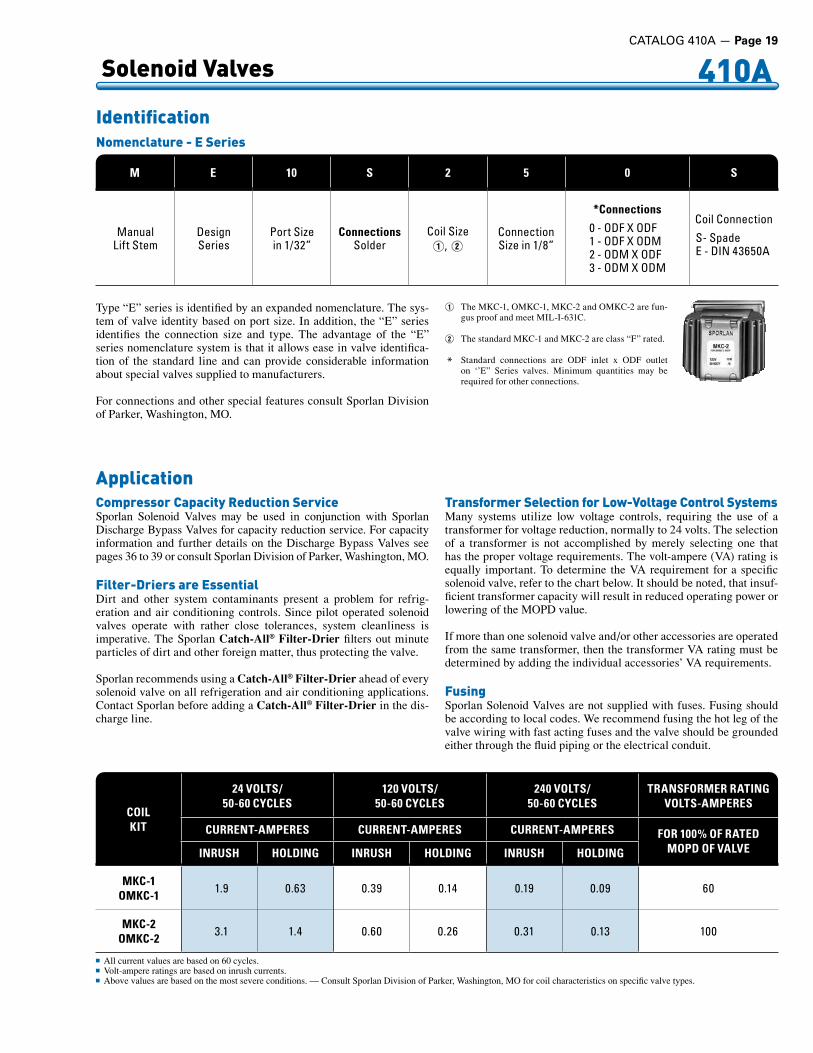
Nomenclature - E Series
Identification
Type “E” series is identified by an expanded nomenclature. The sys-tem of valve identity based on port size. In addition, the “E” series identifies the connection size and type. The advantage of the “E” series nomenclature system is that it allows ease in valve identifica-tion of the standard line and can provide considerable information about special valves supplied to manufacturers.
For connections and other special features consult Sporlan Division of Parker, Washington, MO.
Q The MKC-1, OMKC-1, MKC-2 and OMKC-2 are fun-gus proof and meet MIL-I-631C.
W The standard MKC-1 and MKC-2 are class “F” rated.
* Standard connections are ODF inlet x ODF outlet on ‘’E” Series valves. Minimum quantities may be required for other connections.
M E 10 S 2 5 0 S
ManualLift .Stem
DesignSeries
Port .Sizein .1/32”
ConnectionsSolder
Coil .SizeQ, W
Connection .Size .in .1/8”
*Connections
0 .- .ODF .X .ODF1 .- .ODF .X .ODM2 .- .ODM .X .ODF3 .- .ODM .X .ODM
Coil .Connection
S- .SpadeE .- .DIN .43650A
ApplicationCompressor Capacity Reduction ServiceSporlan Solenoid Valves may be used in conjunction with Sporlan Discharge Bypass Valves for capacity reduction service. For capacity information and further details on the Discharge Bypass Valves see pages 36 to 39 or consult Sporlan Division of Parker, Washington, MO.
Filter-Driers are EssentialDirt and other system contaminants present a problem for refrig-eration and air conditioning controls. Since pilot operated solenoid valves operate with rather close tolerances, system cleanliness is imperative. The Sporlan Catch-All® Filter-Drier filters out minute particles of dirt and other foreign matter, thus protecting the valve.
Sporlan recommends using a Catch-All® Filter-Drier ahead of every solenoid valve on all refrigeration and air conditioning applications. Contact Sporlan before adding a Catch-All® Filter-Drier in the dis-charge line.
Transformer Selection for Low-Voltage Control SystemsMany systems utilize low voltage controls, requiring the use of a transformer for voltage reduction, normally to 24 volts. The selection of a transformer is not accomplished by merely selecting one that has the proper voltage requirements. The volt-ampere (VA) rating is equally important. To determine the VA requirement for a specific solenoid valve, refer to the chart below. It should be noted, that insuf-ficient transformer capacity will result in reduced operating power or lowering of the MOPD value.
If more than one solenoid valve and/or other accessories are operated from the same transformer, then the transformer VA rating must be determined by adding the individual accessories’ VA requirements.
FusingSporlan Solenoid Valves are not supplied with fuses. Fusing should be according to local codes. We recommend fusing the hot leg of the valve wiring with fast acting fuses and the valve should be grounded either through the fluid piping or the electrical conduit.
COILKIT
24 VOLTS/50-60 CYCLES
120 VOLTS/50-60 CYCLES
240 VOLTS/50-60 CYCLES
TRANSFORMER RATING VOLTS-AMPERES
CURRENT-AMPERES CURRENT-AMPERES CURRENT-AMPERES FOR 100% OF RATEDMOPD OF VALVEINRUSH HOLDING INRUSH HOLDING INRUSH HOLDING
MKC-1OMKC-1 1 .9 0 .63 0 .39 0 .14 0 .19 0 .09 60
MKC-2OMKC-2 3 .1 1 .4 0 .60 0 .26 0 .31 0 .13 100
n All current values are based on 60 cycles.n Volt-ampere ratings are based on inrush currents.n Above values are based on the most severe conditions. — Consult Sporlan Division of Parker, Washington, MO for coil characteristics on specific valve types.

Page 20 — CATALOG 410A
410A 3-Way Heat Reclaim Valves
Advantagesn 3-Way Pilot eliminates costly
high-tolow-sideleaks.
n “B”Typereducestotalinstalledcost by eliminating need fornormally open solenoid valveon systems requiring reclaimcondenserpumpout.
n High capacity at minimumpressuredrop.
n Tightsyntheticmainportseating.
n Easilymountedinverticalorhorizontallinetosim-plifypipingrequirements.
n Proven performance backed by Sporlan service,engineeringandtechnicalsupport.
n Standard solenoid coil available at ANY Sporlanwholesaler.
n ULListed,USandCanada File#MH4576,CEApproved
ApplicationValves may be installed in either a horizontal or vertical position. However, it should not be mounted with the coil housing below the valve body.
3-Way Heat Reclaim Valves with 3-way pilot valves are available in a variety of different sizes. These valves are available with an optional “bleed” port, see Figure 1 below. The bleed port allows the refriger-ant to be removed from the heat reclaim coil or heat exchanger when it is not being used. There are two reasons why the refrigerant is
removed from the heat reclaim coil. One is to maintain a proper bal-ance of refrigerant in the system (i.e., refrigerant left in the reclaim coil could result in the remainder of the system operating short of charge). A second reason is to eliminate the potential of having condensed refrigerant in an idle coil. When an idle reclaim coil has condensed or even subcooled liquid refrigerant sitting in the tubes there is a potential for a problem. When refrigerant liquid, either saturated or subcooled, is mixed with hot gas refrigerant, the reaction of the mixing can cause severe liquid hammer. Hot gas mixed with liquid can create thousands of pounds of force and has the potential of breaking refrigerant lines and valves.
An alternate method of removing the refrigerant from a heat reclaim coil is to use a separate normally open solenoid valve and an optional fixed metering device. The separate solenoid valve allows the flex-ibility of pumping out the reclaim heat exchanger as a liquid instead of a vapor. There are two benefits to pumping out the reclaim coil as a liquid: (1) Removal of any oil that may be present in the reclaim heat exchanger. (2) The refrigerating effect of the liquid can be used to lower the superheat of vapor entering the compressor, instead of cooling the heat reclaim heat exchanger.
Sporlan recommends that recognized piping references be consulted for assistance in piping procedures. Sporlan is not responsible for system design, any damage resulting from system design, or for mis-application of its products.
OperationAll Sporlan’s 3-Way Heat Reclaim Valves have a pilot operated design that shifts the refrigerant flow to either the normal condenser or the reclaim condenser based on the heating requirements of the application.
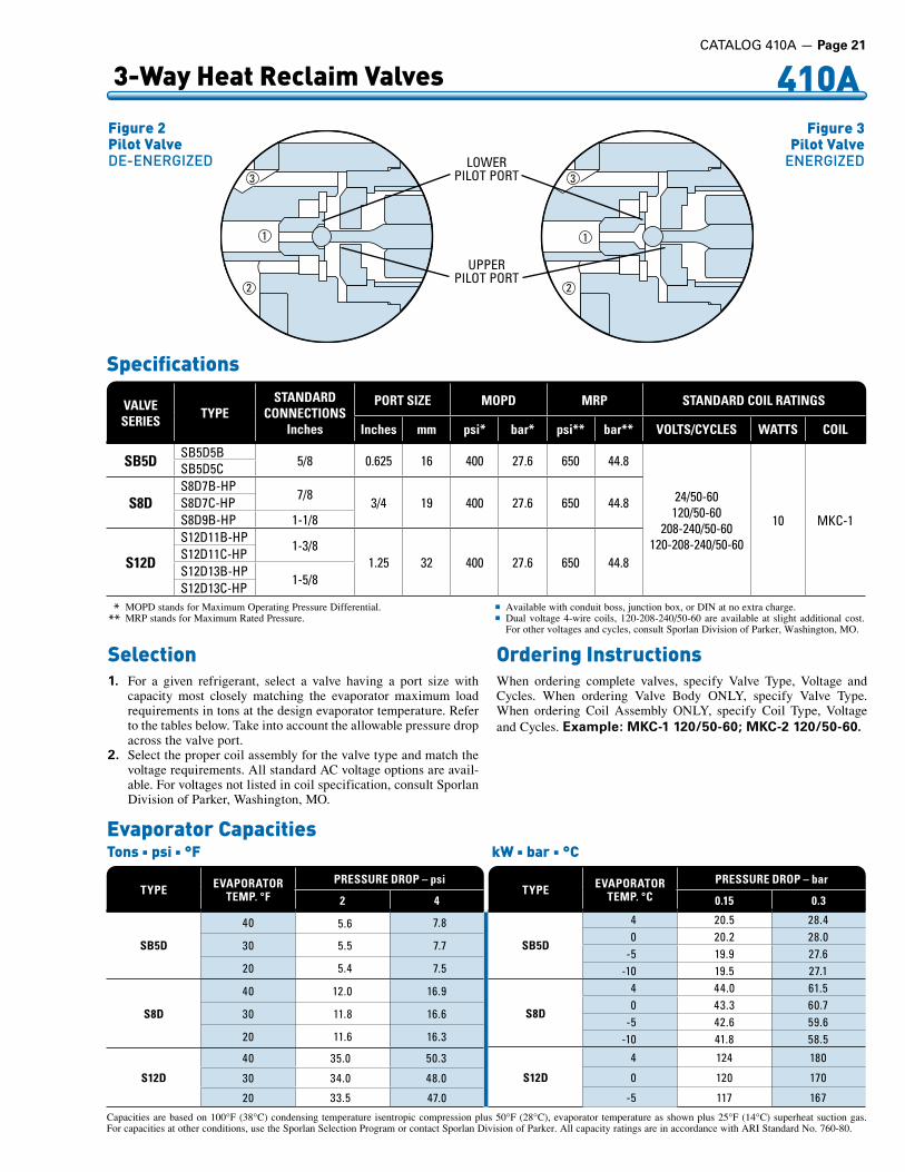
“B” TypeNormal (Outdoor) Condenser – De-energizedSee Figure 2, page 21. With the pilot valve de-energized, high side pressure Q is prevented from entering the cavity above the piston-seat assembly W. At the same time the upper pilot port is opened to suction pressure E. The resulting pressure differential across the piston moves the piston-seat assembly to close the reclaim condenser port (upper main port). In this mode the system refrigerant flows to the normal condenser.
The pilot valve opens the cavity above the piston W, to suction E. This allows the reclaim condenser to be pumped out through a small bleed hole in the piston. The pump out process reduces the reclaim condenser to suction pressure. Once the suction pressure is reached, the flow through the bleed hole in the piston stops. There is no remaining high to low side bleed, with continued operation in the normal condenser mode. For a more efficient pump out of the reclaim condenser, a normally open solenoid valve can be added to the lowest physical location of the heat reclaim coil to remove liquid.
“C” TypeNormal (Outdoor) Condenser – De-energizedSee Bulletin 30-20 for a description of C Type operation.
“B” TypeReclaim (Reheat) Condenser – EnergizedSee Figure 3, page 21. When the pilot valve is energized, high side pressure Q is permitted to flow through the lower pilot port. At the same time, the upper pilot port is closed to suction E. High side pressure Q, builds up on top of the piston, moves the piston-seat assembly to close the normal condenser port, and opens the reclaim (upper) main port. With the upper pilot port closed, there is no high to low side bleed with the system in the reclaim mode.
Type B5D
SuctionConnection
1/4” ODF
Bleed Port
Reclaim Condenser
Type BReclaim Condenser Pump OutFig ure 1
CATALOG 410A — Page 21
410A 3-Way Heat Reclaim Valves
Fig ure 2Pilot ValveDE-ENERGIZED
Fig ure 3Pilot ValveENERGIZED
. * . MOPD stands for Maximum Operating Pressure Differential. .** . MRP stands for Maximum Rated Pressure.
n Available with conduit boss, junction box, or DIN at no extra charge.n . Dual voltage 4-wire coils, 120-208-240/50-60 are available at slight additional cost.
For other voltages and cycles, consult Sporlan Division of Parker, Washington, MO.
VALVE SERIES TYPE
STANDARDCONNECTIONS
Inches
PORT SIZE MOPD MRP STANDARD COIL RATINGS
Inches mm psi* bar* psi** bar** VOLTS/CYCLES WATTS COIL
SB5D SB5D5B5/8 0 .625 16 400 27 .6 650 44 .8
24/50-60120/50-60
208-240/50-60120-208-240/50-60
10 MKC-1
SB5D5C
S8DS8D7B-HP
7/83/4 19 400 27 .6 650 44 .8S8D7C-HP
S8D9B-HP 1-1/8
S12D
S12D11B-HP1-3/8
1 .25 32 400 27 .6 650 44 .8S12D11C-HPS12D13B-HP
1-5/8S12D13C-HP
Specifications
Selection1. For a given refrigerant, select a valve having a port size with
capacity most closely matching the evaporator maximum load requirements in tons at the design evaporator temperature. Refer to the tables below. Take into account the allowable pressure drop across the valve port.
2. Select the proper coil assembly for the valve type and match the voltage requirements. All standard AC voltage options are avail-able. For voltages not listed in coil specification, consult Sporlan Division of Parker, Washington, MO.
Ordering InstructionsWhen ordering complete valves, specify Valve Type, Voltage and Cycles. When ordering Valve Body ONLY, specify Valve Type. When ordering Coil Assembly ONLY, specify Coil Type, Voltage and Cycles. Example: MKC-1 120/50-60; MKC-2 120/50-60.
Evaporator CapacitiesTons n psi n °F kW n bar n °C
TYPE EVAPORATORTEMP. °F
PRESSURE DROP – psi
2 4
SB5D
40 5 .6 7 .8
30 5 .5 7 .7
20 5 .4 7 .5
S8D
40 12 .0 16 .9
30 11 .8 16 .6
20 11 .6 16 .3
S12D
40 35 .0 50 .3
30 34 .0 48 .0
20 33 .5 47 .0
TYPE EVAPORATORTEMP. °C
PRESSURE DROP – bar
0.15 0.3
SB5D
4 20 .5 28 .40 20 .2 28 .0
-5 19 .9 27 .6-10 19 .5 27 .1
S8D
4 44 .0 61 .50 43 .3 60 .7
-5 42 .6 59 .6-10 41 .8 58 .5
S12D
4 124 180
0 120 170
-5 117 167
1
2
3
1
2
3
UPPERPILOT .PORT
LOWERPILOT .PORT
Capacities are based on 100°F (38°C) condensing temperature isentropic compression plus 50°F (28°C), evaporator temperature as shown plus 25°F (14°C) superheat suction gas. For capacities at other conditions, use the Sporlan Selection Program or contact Sporlan Division of Parker. All capacity ratings are in accordance with ARI Standard No. 760-80.

Page 22 — CATALOG 410A
410A 3-Way Heat Reclaim Valves
Dimensions
F
H
C D
A
CompressorDischarge
NormalCondenser
ReclaimCondenser
B
E G
Suction Connection 1/4” ODF
Type SB5D
VALVESERIES TYPE A B C D E F G H J
Inches
SB5DSB5D5B
5 .11 4 .36 3 .22 3 .22 0 .80 5 .11 0 .50 2 .92 1 .64SB5D5C
S8D
S8D7B-HP
5 .11
5 .06
3 .44 3 .44 1 .12 2 .62
0 .75
2 .92 1 .64S8D7C-HP
S8D9B-HP5 .12 0 .91
S8D9C-HP
S12D
S12D11B-HP
6 .73 6 .93 4 .19 4 .19 2 .39 4 .24
0 .97
2 .92 1 .64S12D11C-HP
S12D13B-HP1 .09
S12D13C-HP
mm
SB5DSB5D5B
127 111 82 82 20 98 13 74 42SB5D5C
S8D
S8D7B-HP
125
129
87 87 28 67
19
74 42S8D7C-HP
S8D9B-HP130 23
S8D9C-HP
S12D
S12D11B-HP
171 176 106 106 61 108
25
74 42S12D11C-HP
S12D13B-HP28
S12D13C-HP
H
GE
A
CD
F
BCompressorDischarge
NormalCondenser
ReclaimCondenser
SuctionConnection1/4” ODF
Type S8D
J
Optional 1/2”Conduit Boss
Listed Listed

CATALOG 410A — Page 23
410A AlsoCompatiblewithRefrigerants12,22,134a,404A,407C,502,507
The universal acceptance of the Catch-All® Filter-Drier is due to its unique molded porous core, consisting of a blend of highly effective desiccants. The quality features built into it assure years of service on any refrigeration system.
Moisture – The Catch-All Filter-Drier removes moisture from the refrigerant by adsorbing and retaining it deep within the desiccant granules. The blend of desiccants used in the Catch-All Filter-Drier are specially formulated for exceptional water removal.
Foreign Matter – The Catch-All Filter-Drier will filter out scale, solder particles, carbon, sludge, dirt or any other foreign matter with negligible pressure drop. Fine particles that would go through an ordinary strainer are removed down to a minimum size in one pass filtration. The large filtering area of the Catch-All Filter-Drier core permits it to collect a large amount of dirt without plug up.
Acid – The Catch-All Filter-Drier is unexcelled in acid removal ability. The hydrochloric, hydrofluoric, and various organic acids are adsorbed and held by the desiccant in a manner similar to the
UL and ULC Listed – Guide SMGT-File No. SA-1756A & B. Maximum Rated Pressure of 650 psi, except for the C-140 Series rated at 450 psi and the C-430 Series rated at 500 psi.For complete information see your Sporlan Wholesaler, our website at www.sporlan.com, or write Sporlan and request Bulletin 40-10.
Sealed Type – Liquid Line and Suction Line SpecificationsC US
LISTED
Filter-Driers
“C” SERIES LIQUID LINE TYPE SUCTION LINE TYPE CONNECTION SIZE
InchesVOLUME of DESICCANTCubic Inches
OVERALL LENGTHInches
SOLDER SOCKET DEPTH
Inches
DIAMETER of BODYInchesSAE FLARE ODF SOLDER ODF SOLDER SAE FLARE ODF SOLDER
C-032 C-032-S — 1/4
3
4 .19 3 .81 0 .38
1 .75
— C-032-CAP C-032-CAP-T — Extended .1/4 .Male — 5 .81 —
C-032-F — — 1/4 .Male .- .Inlet1/4 .Female .- .Outlet 3 .81 — —
C-032-FM — — 1/4 .Female .- .Inlet1/4 .Male .- .Outlet 3 .81 — —
C-033 C-033-S — 3/8 4 .69 3 .88 0 .44 C-052
— C-052-S C-0525-S — 1/4
5/16
5
4 .75—
4 .194 .38
0 .380 .44
2 .44 C-052-F — — 1/4 .Male .- .Inlet
1/4 .Female .- .Outlet 4 .19 — —
C-052-FM — — 1/4 .Male .- .Inlet1/4 .Female .- .Outlet 4 .19 — —
C-053 C-053-S — 3/8 5 .19 4 .31 0 .44
C-082—
C-083 C-084
C-082-S C-0825-S C-083-S C-084-S
——
C-083-S-T-HH C-084-S-T-HH
1/45/163/81/2
9
5 .62—
6 .066 .31
5 .125 .315 .255 .44
0 .380 .440 .440 .50
2 .62
C-162—
C-163 C-164 C-165
——
C-162-S C-1625-S C-163-S C-164-S C-165-S
— C-167-S
———
C-164-S-T-HH C-165-S-T-HH C-166-S-T-HH C-167-S-T-HH
1/45/163/81/25/83/47/8
16
6 .25—
6 .756 .947 .25——
5 .755 .945 .886 .006 .316 .756 .93
0 .380 .440 .440 .500 .620 .620 .75
3 .00
C-303 C-304 C-305
———
C-303-S C-304-S C-305-S C-306-S C-307-S C-309-S
——
C-305-S-T-HH C-306-S-T-HH C-307-S-T-HH C-309-S-T-HH
3/81/25/83/47/8
1-1/8
30
9 .699 .8810 .19
———
8 .889 .009 .259 .659 .809 .75
0 .440 .500 .620 .620 .750 .96
3 .00
C-413 C-414 C-415
——
— C-414-S C-415-S C-417-S C-419-S
———
C-417-S-T-HH C-419-S-T-HH
3/81/25/87/8
1-1/8
41
9 .569 .94
10 .25——
—9 .059 .359 .819 .75
—0 .500 .620 .750 .96
3 .50
— —
C-437-S-T-HH C-439-S-T-HH C-4311-S-T-HH C-4313-S-T-HH
7/81-1/81-3/81-5/8
48 —
10 .3410 .7410 .9410 .94
0 .750 .941 .001 .06
4 .75
— C-607-S C-609-S
C-607-S-T-HH C-609-S-T-HH
7/81-1/8 60 — 16 .00
16 .000 .750 .96 3 .00
COMPACT STYLE
C-144-S-TT-HH C-145-S-TT-HH C-146-S-TT-HH C-147-S-TT-HH C-149-S-TT-HH
1/25/83/47/8
1-1/8
14 —
4 .144 .384 .834 .974 .93
0 .500 .660 .660 .750 .96
4 .44

410A AlsoCompatiblewithRefrigerants12,22,134a,404A,407C,502,507
Page 24 — CATALOG 410A
“C” SERIES LIQUID LINE TYPE SUCTION LINE TYPE CONNECTION SIZE
InchesVOLUME of DESICCANT
cm3
OVERALL LENGTHmm
SOLDER SOCKET DEPTH
mm
DIAMETER of BODY
mmSAE FLARE ODF SOLDER ODF SOLDER SAE FLARE ODF SOLDER
C-032 C-032-S — 1/4
49
106 97 10
44
— C-032-CAP C-032-CAP-T — Extended .1/4 .Male — 148 —
C-032-F — — 1/4 .Male .- .Inlet1/4 .Female .- .Outlet 97 — —
C-032-FM — — 1/4 .Female .- .Inlet1/4 .Male .- .Outlet 97 — —
C-033 C-033-S — 3/8 119 99 11 C-052
— C-052-S C-0525-S — 1/4
5/16
82
121—
106111
1011
62 C-052-F — — 1/4 .Male .- .Inlet
1/4 .Female .- .Outlet 106 — —
C-052-FM — — 1/4 .Male .- .Inlet1/4 .Female .- .Outlet 106 — —
C-053 C-053-S — 3/8 132 109 11
C-082—
C-083 C-084
C-082-S C-0825-S C-083-S C-084-S
——
C-083-S-T-HH C-084-S-T-HH
1/45/163/81/2
147
143—154160
130135133138
10111113
67
C-162—
C-163 C-164 C-165
——
C-162-S C-1625-S C-163-S C-164-S C-165-S
— C-167-S
———
C-164-S-T-HH C-165-S-T-HH C-166-S-T-HH C-167-S-T-HH
1/45/163/81/25/83/47/8
262
159—171176184——
146151149152160171176
10111113161619
76
C-303 C-304 C-305
———
C-303-S C-304-S C-305-S C-306-S C-307-S C-309-S
——
C-305-S-T-HH C-306-S-T-HH C-307-S-T-HH C-309-S-T-HH
3/81/25/83/47/8
1-1/8
492
246251259———
226229235245249248
111316161924
76
C-413 C-414 C-415
——
— C-414-S C-415-S C-417-S C-419-S
———
C-417-S-T-HH C-419-S-T-HH
3/81/25/87/8
1-1/8
672
243252260——
—230237249248
—13161924
89
— —
C-437-S-T-HH C-439-S-T-HH C-4311-S-T-HH C-4313-S-T-HH
7/81-1/81-3/81-5/8
787 —
263273278278
19242527
121
— C-607-S C-609-S
C-607-S-T-HH C-609-S-T-HH
7/81-1/8 983 — 406
4061924 76
COMPACT STYLE
. .C-144-S-TT-HH C-145-S-TT-HH C-146-S-TT-HH C-147-S-TT-HH C-149-S-TT-HH
1/25/83/47/8
1-1/8
229 —
105111123126125
1316181924
113
Sealed Type – Liquid Line and Suction Line Specifications
UL and ULC Listed – Guide SMGT-File No. SA-1756A & B. Maximum Rated Pressure of 44.8 bar, except for the C-140 Series rated at 31 bar and the C-430 Series rated at 34.5 bar.For complete information see your Sporlan Wholesaler, our website at www.sporlan.com, or write Sporlan and request Bulletin 40-10.
adsorption of moisture. Tests have demonstrated that the Catch-All Filter-Drier has superior acid removal ability when compared to competitive driers. This ability, along with its excellent ability to clean up the oil, is responsible for the excellent field performance in cleaning up severely contaminated systems.
Oil, Sludge and Varnish – Even the best refrigeration oils break down to produce varnish, sludge and organic acids. Only the Catch-All Filter-Drier is capable of removing these products of oil decomposition.
Special Applications – A special “HH” core Catch-All Filter-Drier is available to remove wax which frequently causes difficulty on low temperature refrigeration systems. For cap tube systems, use the C-032-CAP or C-032-CAP-T Catch-All which has fittings suit-able for attaching to any size capillary tube.
Remember...It’s the CORE that counts!
Filter-Driers
C US
LISTED

CATALOG 410A — Page 25
410A AlsoCompatiblewithRefrigerants12,22,134a,404A,407C,502,507
Filter-Driers
TYPE
ESU
RFA
CE
FILT
ERIN
G A
REA
Squa
re In
ches
WRATINGS AT ARISTANDARD CONDITIONS
SELECTIONRECOMMENDATIONS
(Tons)
WATERCAPACITY- DROPS -
50 PPM
Q
REFRIGERANT FLOW
CAPACITYTons at 1 psi ∆P
AIR CONDITIONING
FIELDREPLACEMENT or
FIELD BUILT UPSYSTEMS75°F 125°F
SEALED TYPEC-032
9 27 201 .4
1/2
C-032-CAPC-032-SC-032-FC-032-FMC-033 3 .4C-033-S 3 .7C-052
15 63 48
2 .03/4 .thru
2
C-052-SC-052-FC-052-FMC-0525-S 3 .3C-053 4 .0C-053-S 4 .5C-082
21 104 78
2 .0
1thru
2
C-082-SC-0825-S 3 .5C-083 4 .4C-083-S 5 .0C-084 7 .9C-084-S 8 .5C-162
33 158 119
2 .0
1-1/2thru
5
C-162-SC-1625-S 3 .5C-163 4 .4C-163-S 5 .0C-164 9 .8C-164-S 10 .7C-165 11 .7C-165-S 13 .4C-303
53 302 227
4 .4
4thru10
C-303-S 5 .0C-304 9 .8C-304-S 10 .7C-305 14 .5C-305-S 16 .4C-307-S 21 .0C-414
67 407 305
11 .1
7-1/2thru15
C-414-S 12 .1C-415 15 .4C-415-S 17 .1C-417-S 21 .5C-419-S 23 .7C-607-S 106 604 454 28 .4 20C-609-S 32 .4
Q Based on 86°F (30°C) liquid line temperature and a refrigerant flow of 2.8 pounds (362 grams) per minute per ton (kW) for Refrigerant 410A. Ratings in accordance to ARI Standard 710.
W 20 drops = 1 gram = 1 cc.
E The filtration area is equal to the core surface area plus the large internal surface available for depth filtration. The variation in flow ratings of filter-driers having the same size core and shell is caused by the difference in connection sizes used.
Sealed TypeLiquid Line Ratings and Selection Recommendations
For complete capacity and selection information see your Sporlan Wholesaler, our website at www.sporlan.com, or write Sporlan and request Bulletin 40-10.
TYPE
ESU
RFA
CE
FILT
ERIN
G A
REA
cm2
WRATINGS AT ARISTANDARD CONDITIONS
SELECTIONRECOMMENDATIONS
(kW)
WATERCAPACITY- GRAMS-
50 PPM
Q
REFRIGERANT FLOW
CAPACITYkW at 0.07 bar
∆P
AIR CONDITIONING
FIELDREPLACEMENT or
FIELD BUILT UPSYSTEMS24°C 52°C
SEALED TYPEC-032
58 1 .4 1 .04 .9
1 .8
C-032-CAPC-032-SC-032-FC-032-FMC-033 11 .9C-033-S 13 .0C-052
97 3 .2 2 .4
7 .02 .6
thru7 .0
C-052-SC-052-FC-052-FMC-0525-S 11 .6C-053 14 .0C-053-S 15 .8C-082
135 5 .2 3 .9
7 .0
3 .5thru7 .0
C-082-SC-0825-S 12 .3C-083 15 .4C-083-S 17 .6C-084 27 .7C-084-S 29 .8C-162
213 7 .9 6 .0
7 .0
5 .3thru17 .6
C-162-SC-1625-S 12 .3C-163 15 .4C-163-S 17 .6C-164 34 .4C-164-S 37 .6C-165 41 .1C-165-S 47 .0C-303
342 15 .1 11 .4
15 .4
14 .1thru35 .2
C-303-S 17 .6C-304 34 .4C-304-S 37 .6C-305 50 .9C-305-S 57 .6C-307-S 73 .7C-414
432 20 .4 15 .3
39 .0
26 .4thru52 .8
C-414-S 42 .5C-415 54 .1C-415-S 60 .0C-417-S 75 .5C-419-S 83 .2C-607-S 684 30 .2 22 .7 99 .7 70 .3C-609-S 113 .7
Tons n °F n psi kW n °C n bar

410A AlsoCompatiblewithRefrigerants12,22,134a,404A,407C,502,507
Page 26 — CATALOG 410A
Filter-Driers
The rugged construction of the Replaceable Core Catch-All has prov-en itself in the field for many years. The design features include:1. The famous molded porous core for maximum contaminant re-
moval. The core cannot swell, powder or pack – assuring ease of installation and removal.
2. The bolt and nut attachment of the end plate provides simple trouble-free installation.
3. The internal construction gives a one piece assembly and assures proper core alignment.
4. A complete line of fitting sizes – all with copper fittings.5. No plastic parts are used – all internal parts are plated steel.6. A corrosion resistant powder paint protects the exterior of the
shell.
UL and ULC Listed – Guide SMGT-File No. SA-1756A & B. C-480 through C-1920 Series shells have a 650 psig (44.8 bar) rating for R-410A.
*Optional Secondary Filter must be purchased separately. O-rings (p/n 621-025) are supplied with each secondary filter, but can be purchased separately. The secondary filter can-not be used if the shell is installed in the suction line.
Type numbers with G suffix indicate that unit is supplied with 1/4” female pipe connection in the end plate and pipe plug. For liquid line service and angle charging valve for system charging purposes can be installed in place of the pipe plug. Angle charging and Schrader type access valves are available from your Sporlan Wholesaler.
Specifications
RCW-48 RC-4864 C-969-G
C US
LISTED
Replaceable Core TypeODF Solder Connections
TYPECONNECTIONS
ODF SOLDERInches
OPTIONAL SECONDARY
FILTER*
NUMBER ofCORES or
FILTER ELEMENTSCORE PART
NUMBER
VOLUME ofDESICCANT
FILTER ELEMENT
PART NUMBERMOUNTING BRACKETS
OVERALLLENGTH
Cubic Inches cm3 Inches mmC-R424-GC-R425-GC-R427-G
1/25/87/8
— 1 RCW-42 42 688 — A-175-19 .009 .069 .44
229230240
C-485-GC-487-GC-489-GC-4811-GC-4813-G
5/87/8
1-1/81-3/81-5/8
FS-480 1
RCW-48,RC-4864 .
orRC-4864-HH
48 787 RPE-48-BD A-685
9 .159 .309 .509 .609 .60
232236241244244
C-967-GC-969-GC-9611-GC-9613-G
7/81-1/81-3/81-5/8
FS-960 2 96 1573 RPE-48-BD A-68514 .8415 .0415 .1415 .14
377382385385
C-1449-GC-14411-GC-14413-G
1-1/81-3/81-5/8
FS-1440 3 144 2360 RPE-48-BD A-68520 .5820 .6820 .68
523525525
C-19211-GC-19213-GC-19217-G
1-3/81-5/82-1/8
FS-19200 4 192 3146 RPE-48-BD A-68526 .2226 .2226 .22
666666666
TYPE
ESU
RFA
CE
FILT
ERIN
G A
REA
Squa
re In
ches
WRATINGS AT ARISTANDARD CONDITIONS
SELECTIONRECOMMENDATIONS
(Tons)
WATERCAPACITY- DROPS -
50 PPM
Q
REFRIGERANT FLOW
CAPACITYTons at 1 psi ∆P
AIR CONDITIONING
FIELDREPLACEMENT or
FIELD BUILT UPSYSTEMS75°F 125°F
REPLACEABLE CORE TYPE WITHHIGH WATER CAPACITY CORES (See page 27)
C-R424-G67 407 305
— 5C-R425-G — 10C-R427-G —C-485-G
64 481 36114 .3 10
C-487-G 23 .3 15C-489-G 42 .2 20C-967-G 128 962 722 38 .3 25C-969-G 47 .5 35C-1449-G 192 1443 1083 57 .9 40C-14411-G 65 .4 50C-19211-G
256 1924 144482 .4 70
C-19213-G 96 .6 80C-19217-G 101 85
Q Based on 86°F (30°C) liquid line temperature and a refrigerant flow of 2.8 pounds (362 grams) per minute per ton (kW) for Refrigerant 410A. Ratings in accordance to ARI Standard 710.
W 20 drops = 1 gram = 1 cc.
E The filtration area is equal to the core surface area plus the large internal surface available for depth filtration.The variation in flow ratings of filter-driers having the same size core and shell is caused by the difference in connection sizes used.
Liquid Line Ratings and Selection Recommendations
TYPE
ESU
RFA
CE
FILT
ERIN
G A
REA
cm2
WRATINGS AT ARISTANDARD CONDITIONS
SELECTIONRECOMMENDATIONS
(kW)
WATERCAPACITY- GRAMS-
50 PPM
Q
REFRIGERANT FLOW
CAPACITYkW at 0.07 bar
∆P
AIR CONDITIONING
FIELDREPLACEMENT or
FIELD BUILT UPSYSTEMS24°C 52°C
REPLACEABLE CORE TYPE WITHHIGH WATER CAPACITY CORES (See page 27)
C-R424-G432 20 .4 15 .3
42 .6 17 .6C-R425-G 60 .1 35 .2C-R427-G 75 .6C-485-G
413 24 .1 18 .150 .3 35 .2
C-487-G 81 .9 52 .8C-489-G 148 70 .3C-967-G 826 48 .1 36 .1 135 87 .9C-969-G 167 123C-1449-G 1239 72 .2 54 .2 204 141C-14411-G 230 176C-19211-G
1652 96 .2 72 .2290 246
C-19213-G 340 281C-19217-G 355 299
Tons n psi n °F kW n bar n °C
For complete information see your Sporlan Wholesaler, our website at www.sporlan.com, or write Sporlan and request Bulletin 40-10.
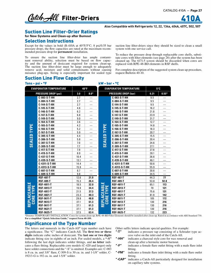
410A AlsoCompatiblewithRefrigerants12,22,134a,404A,407C,502,507
Except for the values in bold (R-410A at 40°F/5°C; 8 psi/0.55 bar pressure drop), the flow capacities are rated at the maximum recom-mended pressure drop for permanent installation.
To ensure the suction line filter-drier has ample contami-nant removal ability, selection must be based on flow capac-ity and the amount of desiccant required for system clean-up. The suction line filter-drier must be large enough to adequately remove acid, moisture and solid contaminants without causing nuisance plug-ups. Sizing is especially important for sealed type
suction line filter-driers since they should be sized to clean a small system with one service call.
To reduce the pressure drop through replaceable core shells, substi-tute cores with filter elements (see page 28) after the system has been cleaned up. The 6171-5 screen should be discarded when cores are replaced with RPE-48-BD elements in RSF shells.
For complete description of the suggested system clean-up procedure, request Bulletin 40-10.
Suction Line Flow CapacityTons n psi n °F kW n bar n °C
*Denotes TEMPORARY INSTALLATION. Cores for system clean-up; RPE-48-BD Filter Elements should be installed after clean-up. Rated in accordance with ARI Standard 730.For a simplified “Quick Selection Guide,” request Form 40-109.
Suction Line Filter-Drier Ratingsfor New Systems and Clean-up after Burnout
Selection Instructions
Filter-Driers
EVAPORATOR TEMPERATURE 40°F
PRESSURE DROP (psi) 3.0 8.0*
SEA
LED
TYP
E
C-083-S-T-HH 2 .7 —C-084-S-T-HH 2 .7 — .C-144-S-T-HH 2 .7 —C-145-S-T-HH 4 .6 —C-146-S-T-HH 6 .2 —C-147-S-T-HH 6 .8 —C-149-S-T-HH 9 .0 —C-164-S-T-HH 3 .6 —C-165-S-T-HH 4 .2 —C-166-S-T-HH 5 .2 —C-167-S-T-HH 5 .9 —C-305-S-T-HH 4 .4 — .C-306-S-T-HH 5 .8 — .C-307-S-T-HH 7 .0 —C-309-S-T-HH 7 .7 —C-417-S-T-HH 7 .9 —C-419-S-T-HH 8 .0 —C-437-S-T-HH 10 .4 —C-439-S-T-HH 13 .1 —C-4311-S-T-HH 14 .4 —C-4313-S-T-HH 15 .9 —C-607-S-T-HH 8 .7 —C-609-S-T-HH 9 .8 —
REPL
ACE
ABL
ECO
RE T
YPE
RSF-487-T 12 .6 21.9RSF-489-T 15 .3 26.4RSF-4811-T 18 .5 32.0RSF-4813-T 19 .9 34.4RSF-4817-T 21 .5 37.3RSF-4821-T 23 .3 40.3RSF-9611-T 29 .8 48.8RSF-9613-T 37 .1 61.3RSF-9617-T 37 .1 61.3RSF-9621-T 37 .1 61.3RSF-9625-T 37 .5 63.4
EVAPORATOR TEMPERATURE 5°C
PRESSURE DROP (bar) 0.21 0.55*
SEA
LED
TYP
E
C-083-S-T-HH 9 .5 —C-084-S-T-HH 9 .5 —C-144-S-T-HH 9 .5 —C-145-S-T-HH 16 .2 —C-146-S-T-HH 21 .8 —C-147-S-T-HH 23 .9 —C-149-S-T-HH 31 .7 —C-164-S-T-HH 12 .7 —C-165-S-T-HH 14 .8 —C-166-S-T-HH 18 .3 —C-167-S-T-HH 20 .7 —C-305-S-T-HH 15 .5 —C-306-S-T-HH 20 .4 —C-307-S-T-HH 24 .6 —C-309-S-T-HH 27 .1 —C-417-S-T-HH 27 .8 —C-419-S-T-HH 28 .1 —C-437-S-T-HH 36 .6 —C-439-S-T-HH 46 .1 —C-4311-S-T-HH 50 .6 —C-4313-S-T-HH 55 .9 —C-607-S-T-HH 30 .6 —C-609-S-T-HH 34 .5 —
REPL
ACE
ABL
ECO
RE T
YPE
RSF-487-T 44 .3 77RSF-489-T 53 .8 92.8RSF-4811-T 65 .1 113RSF-4813-T 70 121RSF-4817-T 75 .6 131RSF-4821-T 81 .9 142RSF-9611-T 105 172RSF-9613-T 130 216RSF-9617-T 130 216RSF-9621-T 130 216RSF-9625-T 132 223
Significance of the Type NumberThe letters and numerals in the Catch-All® type number each have a significance. The “C” indicates Catch-All. The first two or three digits indicate cubic inches of desiccant. The last one or two digits indicate fitting size in eighths of an inch. For sealed models, a “-S” following the last digit indicates solder fittings, and no letter indi-cates a flare fitting. Replaceable core models (C-420 and larger) only have solder connections and the “-S” is omitted. Examples are: C-083 is 8 cu. in. and 3/8” flare, C-309-S is 30 cu. in. and 1-1/8” solder, C-19213-G is 192 cu. in. and 1-5/8” solder.
Other suffix letters indicate special qualities. For example:“-T” indicates a pressure tap consisting of a Schrader type ac-
cess valve on the inlet end of the Catch-All.“-HH” indicates a charcoal style core for wax removal and
clean-up after a hermetic motor burnout.“-F” indicates a female flare outlet fitting with a male flare inlet
fitting.“-FM” indicates a female flare inlet fitting with a male flare outlet
fitting.“-CAP” indicates a Catch-All particularly designed for installation
on capillary tube systems.
CATALOG 410A — Page 27

Page 28 — CATALOG 410A
Cores for replaceable core type filter-driers are molded of exactly the same desiccants that are used in the popular sealed filter-driers.
Cores are individually packed in metal cans, fully activated and her-metically sealed against moisture and dirt.
Filter Elements are dried and packed in individual sealed metal cans. This method of packaging prevents the element from picking up moisture from the atmosphere.
Detailed instructions are printed on each can. Each can contains a “triple gasket” consisting of a new end plate gasket, an end plate gasket for certain competitive filter-driers and a core gasket where desired. See the specifications on page 26 for the number of cores required for each type drier.
RCW-42 – High Water Capacity Core – Order as separate item – Fits ONLY shell type C-R424, C-R425 and C-R427. Designed specially for use with POE oils. This core should be used on systems that have a ruptured water cooled condenser, or that have been exposed to the atmosphere, or for some reason have a high amount of moisture in the system.
RC-4864 – Activated Core – Order as separate item – Fits types C-480 thru C-19200 Series shells and Replaceable Suction Filter (RSF) shells. This is the standard core suitable for most installations in the liquid or suction line applications.
RCW-48 – High Water Capacity Core – Order as separate item – Fits types C-480 thru C-19200 Se-ries shells and Replaceable Suction Filter (RSF) shells. Designed spe-cially for use with POE oils. This core should be used on systems that have a ruptured water cooled condenser, or that have been exposed to the atmosphere, or for some reason have a high amount of moisture in the system.
RC-4864-HH – Activated Charcoal Core – Order as separate item – Fits types C-480 thru C-19200 Series shells and Replaceable Suc-tion Filter (RSF) shells. This core should be used for wax removal on low temperature systems, and for clean-up of systems that have had a hermetic motor burnout.
RPE-48-BD – Filter Element – Order as separate item – Fits types C-480 thru C-19200 Series shells and Replaceable Suction Filter (RSF) shells. This element should be used in RSF shells installed in the suction line to obtain the lowest possible pressure drop. In clean-ing up a system after a hermetic motor burnout, cores should be used first. Then after the system is thoroughly clean, this filter element can be installed in the RSF shell.
Replaceable Cores and Pleated Filter Elements–OrderSeparately
HH Style Catch-All for Wax RemovalSmall amounts of wax are often a problem on low temperature systems. Even well engineered systems frequently contain min-ute quantities of wax which are sufficient to clog expansion valve screens or cause sticking of the valve. Sporlan has developed a spe-cial blend of desiccants including activated charcoal which removes small amounts of wax in the liquid line before this wax can cause trouble at the expansion valve. These Catch-All Filter-Driers have been very successful in correcting trouble jobs in the field.
Select an HH Style Catch-All Filter-Drier if wax problems occur on low temperature systems. In addition to their wax removal ability, these filter-driers will remove all of the other harmful contaminants that the standard filter-driers remove. Listed in the table are various Catch-All models that incorporate the HH style core.
For dimensions, refer to the specifications for standard filter-driers or consult Bulletin 40-10.
410A Filter-Driers
TYPE CONNECTIONSInches TYPE CONNECTIONS
InchesC-052-HH 1/4 .SAE .Flare C-303-HH 3/8 .SAE .FlareC-082-HH 1/4 .SAE .Flare C-304-HH 1/2 .SAE .FlareC-083-HH 3/8 .SAE .Flare C-304-S-HH 1/2 .ODF .SolderC-162-HH 1/4 .SAE .Flare C-305-HH 5/8 .SAE .FlareC-163-HH 3/8 .SAE .Flare C-305-S-HH 5/8 .ODF .SolderC-163-S-HH 3/8 .ODF .Solder C-414-HH 1/2 .SAE .FlareC-164-HH 1/2 .SAE .Flare C-415-HH 5/8 .SAE .FlareC-164-S-HH 1/2 .ODF .Solder C-417-S-HH 7/8 .ODF .SolderC-165-HH 5/8 .SAE .Flare RC-4864-HH Replaceable .
CoreC-165-S-HH 5/8 .ODF .Solder
Design Benefitsn Ashortoveralllength foreasyinstallation.
n Drieroperatesineither flowdirectionwithlowpressuredrop.
n Provenmetalcheckvalvesusedinconstruction–nosyntheticmaterials.
n The Sporlan dependable molded core used formaximumfiltrationability.Whentheflowdirection
reverses,dirtalreadycollectedremainsinthefilter-drier.
n A carefully engineered blend of desiccants formaximum water capacity and acid removal ability.The HPC-160 and HPC-300 series also have an HHstyle core with activated charcoal which offersmaximum ability to remove oleoresin and otherreactivechemicalconstituentsinthelubricant.
n SameruggedconstructionasusedintheCatch-All®.
410A Reversible Heat Pump Filter-Driers
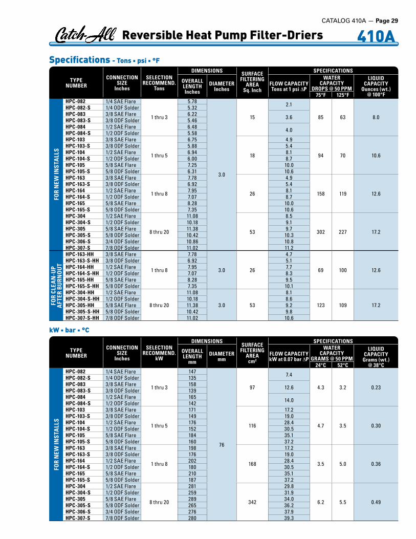
TYPE NUMBER
CONNECTION SIZE
Inches
SELECTIONRECOMMEND.
Tons
DIMENSIONS SURFACE FILTERING
AREASq. Inch
SPECIFICATIONS
OVERALL LENGTHInches
DIAMETERInches
FLOW CAPACITYTons at 1 psi ∆P
WATER CAPACITY
DROPS @ 50 PPM
LIQUID CAPACITY
Ounces (wt.) @ 100°F75°F 125°F
FOR
NEW
INST
ALL
S
HPC-082 1/4 .SAE .Flare
1 .thru .3
5 .78
3 .0
15
2 .1
85 63 8 .0
HPC-082-S 1/4 .ODF .Solder 5 .32HPC-083 3/8 .SAE .Flare 6 .22 3 .6HPC-083-S 3/8 .ODF .Solder 5 .46HPC-084 1/2 .SAE .Flare 6 .48 4 .0HPC-084-S 1/2 .ODF .Solder 5 .58HPC-103 3/8 .SAE .Flare
1 .thru .5
6 .75
18
4 .9
94 70 10 .6
HPC-103-S 3/8 .ODF .Solder 5 .88 5 .4HPC-104 1/2 .SAE .Flare 6 .94 8 .1HPC-104-S 1/2 .ODF .Solder 6 .00 8 .7HPC-105 5/8 .SAE .Flare 7 .25 10 .0HPC-105-S 5/8 .ODF .Solder 6 .31 10 .6HPC-163 3/8 .SAE .Flare
1 .thru .8
7 .78
26
4 .9
158 119 12 .6
HPC-163-S 3/8 .ODF .Solder 6 .92 5 .4HPC-164 1/2 .SAE .Flare 7 .95 8 .1HPC-164-S 1/2 .ODF .Solder 7 .07 8 .7HPC-165 5/8 .SAE .Flare 8 .28 10 .0HPC-165-S 5/8 .ODF .Solder 7 .35 10 .6HPC-304 1/2 .SAE .Flare
8 .thru .20
11 .08
53
8 .5
302 227 17 .2
HPC-304-S 1/2 .ODF .Solder 10 .18 9 .1HPC-305 5/8 .SAE .Flare 11 .38 9 .7HPC-305-S 5/8 .ODF .Solder 10 .42 10 .3HPC-306-S 3/4 .ODF .Solder 10 .86 10 .8HPC-307-S 7/8 .ODF .Solder 11 .02 11 .2
FOR
CLEA
N-U
P A
FTER
BU
RNO
UT
HPC-163-HH 3/8 .SAE .Flare
1 .thru .8
7 .78
3 .0 26
4 .7
69 100 12 .6
HPC-163-S-HH 3/8 .ODF .Solder 6 .92 5 .1HPC-164-HH 1/2 .SAE .Flare 7 .95 7 .7HPC-164-S-HH 1/2 .ODF .Solder 7 .07 8 .3HPC-165-HH 5/8 .SAE .Flare 8 .28 9 .5HPC-165-S-HH 5/8 .ODF .Solder 7 .35 10 .1HPC-304-HH 1/2 .SAE .Flare
8 .thru .20
11 .08
3 .0 53
8 .1
123 109 17 .2HPC-304-S-HH 1/2 .ODF .Solder 10 .18 8 .6HPC-305-HH 5/8 .SAE .Flare 11 .38 9 .2HPC-305-S-HH 5/8 .ODF .Solder 10 .42 9 .8HPC-307-S-HH 7/8 .ODF .Solder 11 .02 10 .6
TYPE NUMBER
CONNECTION SIZE
Inches
SELECTIONRECOMMEND.
kW
DIMENSIONSSURFACE
FILTERING AREAcm2
SPECIFICATIONS
OVERALL LENGTH
mmDIAMETER
mmFLOW CAPACITYkW at 0.07 bar ∆P
WATER CAPACITY
GRAMS @ 50 PPM
LIQUID CAPACITY
Grams (wt.) @ 38°C24°C 52°C
FOR
NEW
INST
ALL
S
HPC-082 1/4 .SAE .Flare
1 .thru .3
147
76
97
7 .4
4 .3 3 .2 0 .23
HPC-082-S 1/4 .ODF .Solder 135HPC-083 3/8 .SAE .Flare 158 12 .6HPC-083-S 3/8 .ODF .Solder 139HPC-084 1/2 .SAE .Flare 165 14 .0HPC-084-S 1/2 .ODF .Solder 142HPC-103 3/8 .SAE .Flare
1 .thru .5
171
116
17 .2
4 .7 3 .5 0 .30
HPC-103-S 3/8 .ODF .Solder 149 19 .0HPC-104 1/2 .SAE .Flare 176 28 .4HPC-104-S 1/2 .ODF .Solder 152 30 .5HPC-105 5/8 .SAE .Flare 184 35 .1HPC-105-S 5/8 .ODF .Solder 160 37 .2HPC-163 3/8 .SAE .Flare
1 .thru .8
198
168
17 .2
3 .5 5 .0 0 .36
HPC-163-S 3/8 .ODF .Solder 176 19 .0HPC-164 1/2 .SAE .Flare 202 28 .4HPC-164-S 1/2 .ODF .Solder 180 30 .5HPC-165 5/8 .SAE .Flare 210 35 .1HPC-165-S 5/8 .ODF .Solder 187 37 .2HPC-304 1/2 .SAE .Flare
8 .thru .20
281
342
29 .8
6 .2 5 .5 0 .49
HPC-304-S 1/2 .ODF .Solder 259 31 .9HPC-305 5/8 .SAE .Flare 289 34 .0HPC-305-S 5/8 .ODF .Solder 265 36 .2HPC-306-S 3/4 .ODF .Solder 276 37 .9HPC-307-S 7/8 .ODF .Solder 280 39 .3
Specifications - Tons n psi n °F
410A Reversible Heat Pump Filter-Driers
kW n bar n °C
CATALOG 410A — Page 29

Page 30 — CATALOG 410A
HPC-100 Series – Core volume is 10 cubic inches (164 cm3). Core surface filtering area is 18 sq. inches (116 cm2). Maximum rated pressure is 650 psig (44.8 bar).HPC-160-HH Series – Core volume is 14 cubic inches (229 cm3). Core surface filtering area is 26 sq. inches (168 cm2). Maximum rated pressure is 650 psig (44.8 bar).HPC-300-HH Series – Core volume is 30 cubic inches (492 cm3). Core filtering area is 53 sq. inches (342 cm2). Maximum rated pressure is 650 psig (44.8 bar).UL and ULC Listed – Guide-SMGT-File No. SA-1756A & B.For complete information see your Sporlan Wholesaler, our website at www.sporlan.com, or write Sporlan and request Bulletin 40-10.
U-Tube Style AccumlatorsThe U-tube accumulator design is a result of extensive laboratory testing plus detailed investigation of the various accumulators cur-rently available. It takes into account essential requirements such as safe holding volume (relative to the system’s total charge), protected flow control for positive refrigerant and oil return, and minimum pressure drop across the accumulator.
Sporlan offers standard accumulator models designed for applica-tion on heat pump and refrigeration systems from 1/4 through 12 tons (0.88 through 42.2 kW). Liquid refrigerant holding requirements of suction accumulator may vary by application. Because of the diver-sity in systems, optimum performance should be determined by the system designer. Consult Sporlan for assistance if required.
Features and Benefitsn Solidcopperconnections
n U-tubedesignformaximumflowofrefrigerantandminimumoilentrapment
n Inlet flow deflector guides refrigerant toward wallforsmoothtangentialflowandgradualexpansion
n U-tube entrance is positioned behind the inlet flowdeflector to prevent unwanted liquid refrigerantfromenteringanddamagingcompressor
n Meteringorificematchedtosystemcapacityassuresoptimumliquidrefrigerantandoilflowbacktocom-pressor
n Protective screen and orifice assembly on U-tubeprotects against contaminants affecting meteringfunction
n Fittings and U-tube are matched to accumulatorholding capacity and total system charge for mini-mumpressuredropandmaximumrefrigerantflow
n U.L.listedfor355psig(24.5bar)maximumworkingpressure.FileNo.SA5172
n Powdercoatingsurpasses500hourASTMsaltspray
n Integral 430°F (221°C) fuse plugs (U.L. File No.SA5441)
Inlet
Mounting Stud.64” / 16.3 mm
Outlet
LengthO.D.
CLCL
Dimensions and Flow DataSee page 30 for dimension values and flow data.
Model PA6
410A Steel Suction Line Accumulators
TYPE NUMBER
CONNECTION SIZE
Inches
SELECTIONRECOMMEND.
kW
DIMENSIONSSURFACE
FILTERING AREAcm2
SPECIFICATIONS
OVERALL LENGTH
mmDIAMETER
mmFLOW CAPACITYkW at 0.07 bar ∆P
WATER CAPACITY
GRAMS @ 50 PPM
LIQUID CAPACITY
Grams (wt.) @ 38°C24°C 52°C
FOR
CLEA
N-U
P A
FTER
BU
RNO
UT
HPC-163-HH 3/8 .SAE .Flare
1 .thru .8
198
76 168
16 .5
3 .5 5 .0 0 .36
HPC-163-S-HH 3/8 .ODF .Solder 176 17 .9HPC-164-HH 1/2 .SAE .Flare 202 27 .0HPC-164-S-HH 1/2 .ODF .Solder 180 29 .1HPC-165-HH 5/8 .SAE .Flare 210 33 .3HPC-165-S-HH 5/8 .ODF .Solder 187 35 .5HPC-304-HH 1/2 .SAE .Flare
8 .thru .20
281
76 342
28 .4
6 .2 5 .5 0 .49HPC-304-S-HH 1/2 .ODF .Solder 259 30 .2HPC-305-HH 5/8 .SAE .Flare 289 32 .3HPC-305-S-HH 5/8 .ODF .Solder 265 34 .4HPC-307-S-HH 7/8 .ODF .Solder 280 37 .2

Dimensions and Flow Data Tons n psi n °F kW n bar n °C
MODEL NUMBER
CONN.Inches(ODF)
DIMENSIONSInches
CAPA
CITY
Oun
ces*
(wt.) EVAP.
TEMP.°F
RECOMMENDEDCAPACITY OF
REFRIGERATION
LENGTH O.D. Tons @1 psi
Min.Tons
PA3060-10-4PA3060-10-5
1/25/8
10 .3510 .35
33
3232
40 1 .93 1 .440 1 .50 0 .65
-20 1 .30 0 .42
PA3060-15-5 5/8 15 .05 3 5040 2 .02 1 .440 1 .57 0 .65
-20 1 .36 0 .42
PA3060-15-6 3/4 15 .05 3 4940 2 .22 1 .440 1 .72 0 .65
-20 1 .49 0 .42
PA4065-9-5C 5/8 9 .62 4 5540 2 .85 1 .440 2 .21 0 .65
-20 1 .93 0 .42
PA4065-9-6C 3/4 9 .62 4 5340 2 .89 1 .440 2 .23 0 .65
-20 1 .95 0 .42
PA5083-9-6C 3/4 9 .62 5 8140 3 .68 2 .160 2 .86 0 .98
-20 2 .48 0 .63
PA5083-9-7C 7/8 9 .63 5 7840 3 .76 2 .160 2 .91 0 .98
-20 2 .53 0 .63
PA5083-12-7C 7/8 12 .88 5 11440 5 .21 3 .030 4 .05 1 .37
-20 3 .52 0 .88
PA5083-11-7C 7/8 11 .33 5 9840 4 .22 2 .160 3 .27 0 .98
-20 2 .84 0 .63
PA5083-11-6C 3/4 11 .33 5 10140 3 .71 2 .160 2 .88 0 .98
-20 2 .49 0 .63
PA5083-15-7C 7/8 15 .34 5 14240 5 .97 3 .030 4 .64 1 .37
-20 4 .02 0 .88
PA5083-17-7C 7/8 17 .25 5 16340 5 .97 3 .030 4 .64 1 .37
-20 4 .02 0 .88
PA6125-15-9C 1-1/8 15 .00 6 19240 8 .67 4 .930 5 .44 2 .23
-20 4 .19 1 .43
PA6125-15-11C 1-3/8 15 .25 6 19540 11 .56 4 .930 7 .28 2 .23
-20 5 .65 1 .43
PA6125-18-9C 1-1/8 18 .00 6 24040 8 .48 4 .930 5 .34 2 .23
-20 4 .19 1 .43
PA6125-18-11C 1-3/8 18 .00 6 24340 10 .59 4 .930 6 .80 2 .23
-20 5 .26 1 .43
PA6125-20-11C 1-3/8 20 .25 6 27540 10 .59 4 .930 6 .80 2 .23
-20 5 .26 1 .43*Holding capacity of R-410A at 40°F (5°C). Divide by 0.7 to obtain recommended maximum system charge on fixed orifice systems. Consult Sporlan for availability.
For complete information see your Sporlan Wholesaler, our website at www.sporlan.com, or write Sporlan and request Bulletin 40-10-7.
410A Steel Suction Line Accumulators
MODEL NUMBER
CONN.Inches(ODF)
DIMENSIONSmm
CAPA
CITY
Gra
ms*
(wt.) EVAP.
TEMP.°C
RECOMMENDEDCAPACITY OF
REFRIGERATION
LENGTH O.D. kW @ 0.07 bar
Min.kW
PA3060-10-4PA3060-10-5
1/25/8
263263
76 .276 .2
907907
4 6 .79 5 .06-18 5 .28 2 .29-29 4 .57 1 .48
PA3060-15-5 5/8 382 76 .2 14174 7 .10 5 .06
-18 5 .52 2 .29-29 4 .78 1 .48
PA3060-15-6 3/4 382 76 .2 13894 7 .81 5 .06
-18 6 .05 2 .29-29 5 .24 1 .48
PA4065-9-5C 5/8 244 102 15594 10 .0 5 .06
-18 7 .77 2 .29-29 6 .79 1 .48
PA4065-9-6C 3/4 244 102 15034 10 .2 5 .06
-18 7 .84 2 .29-29 6 .86 1 .48
PA5083-9-6C 3/4 244 127 22964 12 .9 7 .60
-18 10 .1 3 .45-29 8 .72 2 .22
PA5083-9-7C 7/8 245 127 22114 13 .2 7 .60
-18 10 .2 3 .45-29 8 .9 2 .22
PA5083-12-7C 7/8 327 127 32324 18 .3 10 .7
-18 14 .2 4 .82-29 12 .4 3 .09
PA5083-11-7C 7/8 287 127 27784 14 .8 7 .60
-18 11 .5 3 .45-29 9 .99 2 .22
PA5083-11-6C 3/4 287 127 28634 13 .0 7 .60
-18 10 .1 3 .45-29 8 .76 2 .22
PA5083-15-7C 7/8 390 127 40264 21 .0 10 .7
-18 16 .3 4 .82-29 14 .1 3 .09
PA5083-17-7C 7/8 438 127 46214 21 .0 10 .7
-18 16 .3 4 .82-29 14 .1 3 .09
PA6125-15-9C 1-1/8 381 152 54434 30 .5 17 .3
-18 19 .1 7 .84-29 14 .7 5 .03
PA6125-15-11C 1-3/8 387 152 55284 40 .7 17 .3
-18 25 .6 7 .84-29 19 .9 5 .03
PA6125-18-9C 1-1/8 457 152 68044 29 .8 17 .3
-18 18 .8 7 .84-29 14 .7 5 .03
PA6125-18-11C 1-3/8 457 152 68894 37 .2 17 .3
-18 23 .9 7 .84-29 18 .5 5 .03
PA6125-20-11C 1-3/8 514 152 77964 37 .2 17 .3
-18 23 .9 7 .84-29 18 .5 5 .03
CATALOG 410A — Page 31

Page 32 — CATALOG 410A
410A AlsoCompatiblewithRefrigerants12,22,134a,404A,407C,502,507
SA-12FM SA-14U SA-13UU SA-13FU SA-14SU SA-17S SA-217
Specifications - Inches
CONNEC-TION SIZESInches
MALE FLARE FEMALE & MALE FLARE
MALE FLARE x SWIVEL NUT
SWIVEL NUT xSWIVEL NUT
FEMALE FLARE x SWIVEL NUT
SWIVEL NUT x ODF SOLDER ODF SOLDER
TYPE NO.
OVERALL LENGTHInches
TYPE NO.OVERALL LENGTHInches
TYPE NO.
OVERALL LENGTHInches
TYPE NO.
OVERALL LENGTHInches
TYPE NO.
OVERALL LENGTHInches
TYPE NO.
OVERALL LENGTHInches
TYPENO.
OVERALL LENGTHInches
1/4 SA-12 2 .87 SA-12FM 2 .56 — — — — — — — — SA-12S 4 .623/8 SA-13 3 .37 SA-13FM 2 .97 SA-13U 3 .64 SA-13UU 3 .95 SA-13FU 3 .19 SA-13SU 4 .19 SA-13S1/2 SA-14 3 .81 SA-14FM 3 .44 SA-14U 4 .13 SA-14UU 4 .50 SA-14FU 3 .75 SA-14SU 4 .62 SA-14S 4 .875/8 SA-15 4 .13 — — SA-15U 4 .44 SA-15UU 4 .75 — — SA-15SU 4 .89 SA-15S7/8 — — — — — — — — — — — — SA-17S 6 .311-1/8 — — — — — — — — — — — — SA-19S
1-3/8 — — — — — — — — — — — — QSA-2117 .971-5/8 — — — — — — — — — — — — QSA-213
2-1/8 — — — — — — — — — — — — QSA-217
Maximum Rated Pressure for all models is 650 psig (44.8 bar). Overall width is: 1.31” (33.3 mm) for 1/4” and 3/8” sizes. 1.58” (40.1 mm) for 1/2” and 5/8 sizes, and 1.38” (35.1 mm) for 7/8” and 1-1/8” sizes. Most solder connections can be used as male fittings as well as female fittings. The 1/4” ODF is 3/8” ODM, the 3/8” ODF is 1/2” ODM, the 1/2” ODF is 5/8” ODM, and the 5/8” ODF is 3/4” ODM. Models with female flare and/or swivel nut connections are supplied with a copper gasket in the fitting.
Q These models have copper connections and feature a removable element cartridge – for replacement cartridge specify AC-20.
Listed by Underwriters’ Laboratories, Inc. – Guide SEYW – File No. SA3182
Note: Change or add Catch-All Filter-Drier when paper turns from green to chartreuse.
1. One indicator for refrigerants 12, 22, 134a, 404A, 407C, 410A, 502 and 507. The See•All Moisture and Liquid Indica-tor provides a true moisture indication for Refrigerants 12, 22, 134a, 404A, 407C, 410A, 502 and 507. The See•All® is also suit-able for Refrigerants 401A & B, 402 A & B, 408A and 409A. The dark green indicates dry and a bright yellow indicates wet. The one indicator avoids the confusion found in models with two elements. You cannot pick the wrong element when checking the moisture content of the system.
2. Reliable and accurately calibrated color change points. The See•All Moisture and Liquid Indicator is accurately cali-brated in parts per million of moisture for each refrigerant. All moisture indicators change color on the basis of relative satura-tion of the refrigerant. Therefore, liquid line temperature must be considered if an accurate calibration is to be obtained. For easy comparison, a color chart is part of the label.
3. Color changes are easily distinguished and reversible. The indicator’s color differs so widely between WET and DRY conditions that there is no possibility of confusion between the two. Colors will reverse as often as moisture concentration in the system changes.
4. Large full view sight glass. The See•All Moisture and Liq-uid Indicator has an extra large crystal clear sight glass for view-ing the refrigerant. Bubbles indicate a shortage of refrigerants or a restriction in the liquid line.
5. Indicator protected from discoloration and dirt. The in-dicator is protected by a filter pad and screen. This prevents wash-ing of the indicator by the refrigerant and protects it from system contamination and turbulence.
6. Replaceable indicator element. The color indicator paper can be changed on the new fused glass models without removing the See•All from the line. Replacement is through the bottom (see SA-14SU below). Request the K-SA-4 kit.
7. Disassembly of the smaller sizes not required. The ex-tended fittings on solder models in the smaller sizes make it un-necessary to disassemble for installation.
8. A double duty plastic cap is supplied to keep the glass free from dust, dirt and grease. It also permits the service engineer to use his own discretion concerning instructions to his customers on observing the See•All Moisture and Liquid Indicator.
8 Outstanding Benefits
Moisture and Liquid Indicator
CONNEC-TION SIZESInches
MALE FLARE FEMALE & MALE FLARE
MALE FLARE x SWIVEL NUT
SWIVEL NUT xSWIVEL NUT
FEMALE FLARE x SWIVEL NUT
SWIVEL NUT x ODF SOLDER ODF SOLDER
TYPE NO.
OVERALL LENGTH
mmTYPE NO.
OVERALL LENGTH
mmTYPE NO.
OVERALL LENGTH
mmTYPE NO.
OVERALL LENGTH
mmTYPE NO.
OVERALL LENGTH
mmTYPE NO.
OVERALL LENGTH
mmTYPENO.
OVERALL LENGTH
mm1/4 SA-12 72 .9 SA-12FM 65 .0 — — — — — — — — SA-12S 1173/8 SA-13 85 .6 SA-13FM 75 .4 SA-13U 92 .5 SA-13UU 100 SA-13FU 81 SA-13SU 106 SA-13S1/2 SA-14 96 .8 SA-14FM 87 .4 SA-14U 105 SA-14UU 114 SA-14FU 95 .3 SA-14SU 117 SA-14S 1245/8 SA-15 105 — — SA-15U 113 SA-15UU 121 — — SA-15SU 124 SA-15S7/8 — — — — — — — — — — — — SA-17S 1601-1/8 — — — — — — — — — — — — SA-19S
1-3/8 — — — — — — — — — — — — QSA-2112021-5/8 — — — — — — — — — — — — QSA-213
2-1/8 — — — — — — — — — — — — QSA-217
mm
Moisture Content PPM
SEE•ALL SHOWSR-410A LIQUID LINE TEMPERATURE
75°F 24°CGreen DRY Below .75Chartreuse CAUTION 75-150Yellow WET Above .150
For complete information see your Sporlan Wholesaler, our website at www.sporlan.com, or write Sporlan and request Bulletin 70-10.

The Replaceable Suction Filter shell, used with RPE-48-BD pleated filter element, is designed to be installed in the suction line of new systems to remove circulating contaminants.
Design Benefitsn Highflowcapacity
n Corrosionresistantcoatingonshell
n Canbeusedwithdesiccantcores forclean-upafterburnout
n Variousfittingsizesupto3-1/8”linesize
n Accessvalvesuppliedforpressuredrop measurementorcharging
How It’s UsedSporlan Replaceable Suction Filters are installed in the suction line of refrigeration or air conditioning systems to remove contaminants that may be in the system at startup.
The Replaceable Suction Filter has large fittings permitting the use of a small shell on a system with large line sizes, resulting in consid-erable economy. The angle construction is suitable of flow in either direction, which results in easy installation even on compact racks.
The Replaceable Suction Filters should be used with cores for clean-ing up a system after a hermetic motor burnout. Select the RC-4864, RC-4864-HH or RCW-48 replaceable cores. After cleanup, install RPE-48-BD elements in the shells.
SelectionThe table below gives information for choosing the proper model for a given system. The filter elements are supplied in hermetically sealed metal cans. For flow capacity WITH CORES, see page 27.
Listed by Underwriters’ Laboratories, Inc. Guide SMGT File No. SA-1756A & B. RSF shells have a 500 psig (34.5 bar) M.R.P. rating.Note: Ratings are in accordance with ARI Standards 730. Flow capacity (tons/kW) with cores is approximately 40% of the above values.For complete information see your Sporlan Wholesaler, our website at www.sporlan.com, or write Sporlan and request Bulletin 80-10.
410A Replaceable
RSF-4817-T
Flow Capacity - Tons n psi n °F kW n bar n °C
TYPE
CON
NEC
TIO
NS
Inch
esO
DF
SOLD
ER
FLOW CAPACITY
NU
MB
ER O
F FI
LTER
EL
EMEN
TS
FILT
ER A
REA
Squa
re In
ches
OVE
RALL
LEN
GTH
Inch
esEVAPORATOR
TEMPERATURE40°F
PRESSURE DROP – psi1 2 3
RSF-487-T 7/8 8 .0 11 .3 13 .8
OneRPE-48-BD 388
9 .30RSF-489-T 1-1/8 12 .7 18 .0 22 9 .37RSF-4811-T 1-3/8 18 .5 26 .1 32 9 .60RSF-4813-T 1-5/8 23 .7 33 .5 41 9 .60RSF-4817-T 2-1/8 31 .8 44 .9 55 9 .37RSF-4821-T 2-5/8 41 .6 58 .8 72 9 .75RSF-9611-T 1-3/8 20 .8 29 .4 36
TwoRPE-48-BD 776
15 .14RSF-9613-T 1-5/8 27 .1 38 .4 47 15 .14RSF-9617-T 2-1/8 34 .1 48 .2 59 14 .96RSF-9621-T 2-5/8 46 .8 66 .1 81 15 .43RSF-9625-T 3-1/8 64 .1 90 .6 111 15 .12
TYPE
CON
NEC
TIO
NS
Inch
esO
DF
SOLD
ER
FLOW CAPACITY
NU
MB
ER O
F FI
LTER
EL
EMEN
TS
FILT
ER A
REA
cm2
OVE
RALL
LEN
GTH
mm
EVAPORATORTEMPERATURE
5°CPRESSURE DROP – bar0.07 0.14 0.21
RSF-487-T 7/8 28 .1 39 .7 48 .5
OneRPE-48-BD 2503
236RSF-489-T 1-1/8 44 .7 63 .3 77 .4 238RSF-4811-T 1-3/8 65 .1 91 .8 113 244RSF-4813-T 1-5/8 83 .3 118 144 244RSF-4817-T 2-1/8 112 158 193 238RSF-4821-T 2-5/8 146 207 253 248RSF-9611-T 1-3/8 73 .2 103 127
TwoRPE-48-BD 5006
385RSF-9613-T 1-5/8 95 .3 135 165 385RSF-9617-T 2-1/8 120 170 207 380RSF-9621-T 2-5/8 165 232 285 392RSF-9625-T 3-1/8 225 319 390 384
Designed to Test Mineral, Alkylbenzene and POE Lubricants
n Thoroughlyfieldproven
n Takestheguessworkout ofservicework
Design Benefitsn Builds Customer Confidence – Show the test results of the
acid test kit to customers, or perform the test in their presence. In this way they realize you are using the most up-to-date scien-tific method for system maintenance. Showing customers the test results will also help to convince them to spend the money neces-sary to do a proper clean-up job. Customers who are thoroughly confident of your abilities will be more interested in establishing preventive maintenance programs.
n Accurate and Reliable – Using a simple, scientific method, you can precisely measure the amount of acid in a lubricant sample taken from a contaminated system. The test procedure has been proven by extensive field experience.
n Convenient – Both the TA-1 and AK-3 are convenient to use.
The TA-1 has pre-measured solutions supplied in bottles with screw caps for easy handling. The AK-3 has all solutions and bottles supplied in a small fitted case. Either kit may be used on the job site, or a lubricant sample can be saved and tested in the presence of the equipment owner.
n Lubricant Sample Used for Test – Since lubricant is the scav-enger, it gives the best indication of acid in the system. Less than an ounce of lubricant is required.
n Quick to Use – Once the lubricant sample is obtained...it will take only minutes to perform the test. Simply mix the solutions and lubricant to be tested. Shake, and the resulting color tells the complete story.
n Cost – The cost of the test is very inexpensive, regardless of which kit is used. The TA-1 Kit is more convenient, but for re-peated testing the AK-3 is less costly.
Both the TA-1 and AK-3 Kits are normally used on a “pass or fail” basis. If the user desires and indication of the relative amount of acid in the lubricant, then the AK-3 Kit should be selected.
For complete information see your Sporlan Wholesaler, our website at www.sporlan.com, or write Sporlan and request Bulletin 40-10.
Acid Test Kits - Type TA-1 and AK-3
TA-1
CATALOG 410A — Page 33

Page 34 — CATALOG 410A
410A Head Pressure Control Valves
High and Low Ambient StabilityThe design of air conditioning systems utilizing air cooled condens-ing units involves two main problems that must be solved if the sys-tem is to operate reliably and economically . . . high ambient and low ambient operation. If the condensing unit is properly sized, it will operate satisfactorily during extremely high ambient tempera-tures. However, some units will be required to operate at ambient temperatures below their design dry bulb temperature during most of the year, the solution to low ambient operation is more complex.
Without good head pressure control during low ambient operation, the system can experience both running cycle and off-cycle problems. Since the pressure differential across the thermostatic expansion valve port affects the rate of refrigerant flow, low head pressure generally causes insufficient refrigerant to be fed to the evaporator. Failure to have sufficient head pressure will result in low suction pressure and/or iced evaporator coils.
The primary off-cycle problem is refrigerant migration to the con-denser. Insufficient flow through the TEV will cause a low suction pressure.
The typical method of maintaining normal head pressure in a refrig-eration system during periods of low ambient temperature is to restrict liquid flow from the condenser to the receiver, and at the same time divert hot gas to the inlet of the receiver. This backs liquid refrigerant up into the condenser reducing its capacity which in turn increases the condensing pressure. At the same time the hot gas raises liquid pressure in the receiver, allowing the system to operate normally.
OperationLAC-4 The valve designation LAC stands for Low Ambient Control. The LAC-4 is a three way modulating valve that responds to discharge pressure. As shown in Figure 4, the discharge pressure bleeds around the pushrod to the underside of the diaphragm. The discharge pres-sure opposes the dome pressure. When the outdoor ambient falls, the condensing pressure falls. This causes the discharge pressure to
fall as well. When the discharge pressure falls below the dome pres-sure, the valve modulates open to the discharge port which allows discharge gas to bypass the condenser. Mixing the discharge gas with the liquid creates a high pressure at the condenser outlet, reducing the flow and causing liquid to back up in the condenser. Flooding the condenser reduces the area available for condensing. This reduction in effective condenser surface area results in a rise in condensing
pressure. During summer conditions, the discharge pressure is high thus closing the discharge port. Hence, there is full liquid flow from the condenser to the receiver.
LAC-5 and LAC-10The LAC-5 and LAC-10 are also three-way modulating valves but they respond to receiver pressure. As shown in Figure 5, the receiver pressure acts under the diaphragm. As the receiver pressure drops below the valve setting, the seat moves away from the discharge port allowing discharge gas to bypass the condenser. This discharge gas warms the liquid in the receiver and raises the pressure to the valve setting. At the same time discharge gas is bypassing the condenser, liquid flow from the condenser is restricted, which allows liquid to back up in the condenser. Flooding the condenser reduces the area available for condensing thus raising the condensing pressure. During summer conditions, the seat closes the discharge port due to high pressure in the receiver. Therefore, there is full liquid flow from the condenser to the receiver.
Refrigerant MigrationDuring an off cycle there is a potential for refrigerant to migrate from the warm receiver to the cold condenser. An auxiliary check valve should be used in the liquid line between the LAC and the receiver to prevent this from occurring. See Figure 6.
Piping SuggestionsThe piping schematic shown in Figure 6 is only to illustrate the general location of the head pressure control valves in the system. Sporlan recommends that recognized piping references be consulted for assistance in piping procedures. Sporlan is not responsible for sys-tem design, any damage arising from faulty system design, or for mis-application of its products. If these valves are applied in any manner other than as describe in this bulletin, the Sporlan warranty is void.Discharge
Receiver
CondenserFig ure 4LAC-4
SolenoidValve
Catch-All
Compressor
See-All
TEV
External Equalizer
Check Valve
LAC
Receiver
Evaporator
Distributor
Condenser
Fig ure 6
Discharge
Receiver
CondenserFig ure 5LAC-5, LAC-10
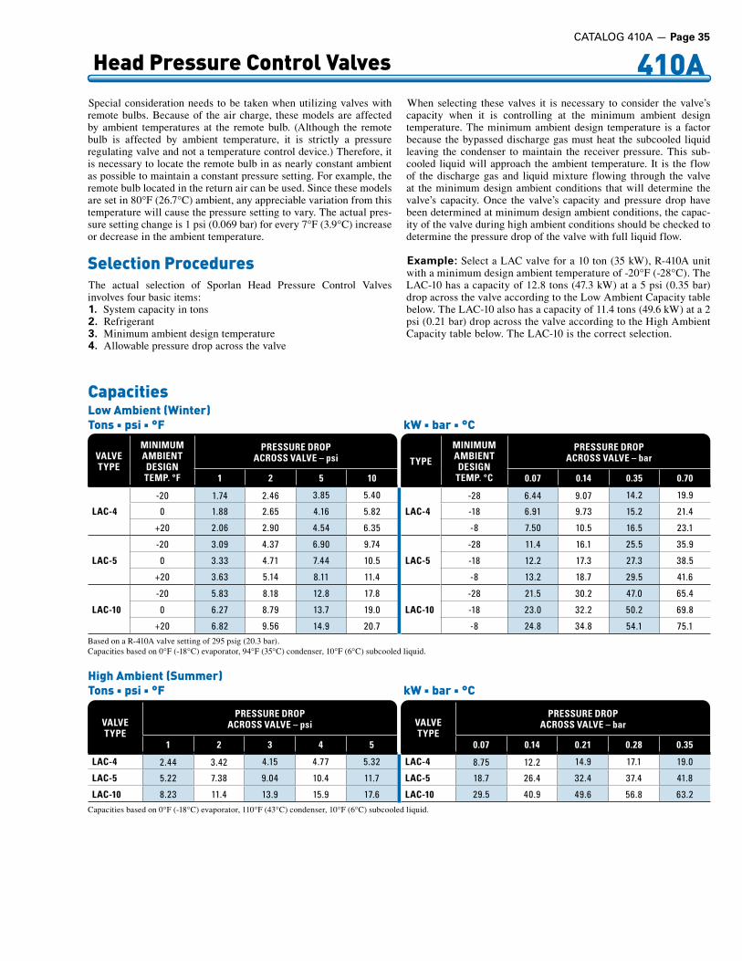
410A Head Pressure Control Valves
CapacitiesLow Ambient (Winter)Tons n psi n °F kW n bar n °C
VALVETYPE
MINIMUMAMBIENTDESIGNTEMP. °F
PRESSURE DROPACROSS VALVE – psi
1 2 5 10
LAC-4
-20 1 .74 2 .46 3 .85 5 .40
0 1 .88 2 .65 4 .16 5 .82
+20 2 .06 2 .90 4 .54 6 .35
LAC-5
-20 3 .09 4 .37 6 .90 9 .74
0 3 .33 4 .71 7 .44 10 .5
+20 3 .63 5 .14 8 .11 11 .4
LAC-10
-20 5 .83 8 .18 12 .8 17 .8
0 6 .27 8 .79 13 .7 19 .0
+20 6 .82 9 .56 14 .9 20 .7Based on a R-410A valve setting of 295 psig (20.3 bar).Capacities based on 0°F (-18°C) evaporator, 94°F (35°C) condenser, 10°F (6°C) subcooled liquid.
TYPE
MINIMUMAMBIENTDESIGN
TEMP. °C
PRESSURE DROPACROSS VALVE – bar
0.07 0.14 0.35 0.70
LAC-4
-28 6 .44 9 .07 14 .2 19 .9
-18 6 .91 9 .73 15 .2 21 .4
-8 7 .50 10 .5 16 .5 23 .1
LAC-5
-28 11 .4 16 .1 25 .5 35 .9
-18 12 .2 17 .3 27 .3 38 .5
-8 13 .2 18 .7 29 .5 41 .6
LAC-10
-28 21 .5 30 .2 47 .0 65 .4
-18 23 .0 32 .2 50 .2 69 .8
-8 24 .8 34 .8 54 .1 75 .1
VALVETYPE
PRESSURE DROPACROSS VALVE – psi
1 2 3 4 5
LAC-4 2 .44 3 .42 4 .15 4 .77 5 .32
LAC-5 5 .22 7 .38 9 .04 10 .4 11 .7
LAC-10 8 .23 11 .4 13 .9 15 .9 17 .6Capacities based on 0°F (-18°C) evaporator, 110°F (43°C) condenser, 10°F (6°C) subcooled liquid.
High Ambient (Summer)Tons n psi n °F kW n bar n °C
VALVETYPE
PRESSURE DROPACROSS VALVE – bar
0.07 0.14 0.21 0.28 0.35
LAC-4 8 .75 12 .2 14 .9 17 .1 19 .0
LAC-5 18 .7 26 .4 32 .4 37 .4 41 .8
LAC-10 29 .5 40 .9 49 .6 56 .8 63 .2
Special consideration needs to be taken when utilizing valves with remote bulbs. Because of the air charge, these models are affected by ambient temperatures at the remote bulb. (Although the remote bulb is affected by ambient temperature, it is strictly a pressure regulating valve and not a temperature control device.) Therefore, it is necessary to locate the remote bulb in as nearly constant ambient as possible to maintain a constant pressure setting. For example, the remote bulb located in the return air can be used. Since these models are set in 80°F (26.7°C) ambient, any appreciable variation from this temperature will cause the pressure setting to vary. The actual pres-sure setting change is 1 psi (0.069 bar) for every 7°F (3.9°C) increase or decrease in the ambient temperature.
Selection ProceduresThe actual selection of Sporlan Head Pressure Control Valves involves four basic items:1. System capacity in tons2. Refrigerant3. Minimum ambient design temperature4. Allowable pressure drop across the valve
When selecting these valves it is necessary to consider the valve’s capacity when it is controlling at the minimum ambient design temperature. The minimum ambient design temperature is a factor because the bypassed discharge gas must heat the subcooled liquid leaving the condenser to maintain the receiver pressure. This sub-cooled liquid will approach the ambient temperature. It is the flow of the discharge gas and liquid mixture flowing through the valve at the minimum design ambient conditions that will determine the valve’s capacity. Once the valve’s capacity and pressure drop have been determined at minimum design ambient conditions, the capac-ity of the valve during high ambient conditions should be checked to determine the pressure drop of the valve with full liquid flow.
Example: Select a LAC valve for a 10 ton (35 kW), R-410A unit with a minimum design ambient temperature of -20°F (-28°C). The LAC-10 has a capacity of 12.8 tons (47.3 kW) at a 5 psi (0.35 bar) drop across the valve according to the Low Ambient Capacity table below. The LAC-10 also has a capacity of 11.4 tons (49.6 kW) at a 2 psi (0.21 bar) drop across the valve according to the High Ambient Capacity table below. The LAC-10 is the correct selection.
CATALOG 410A — Page 35
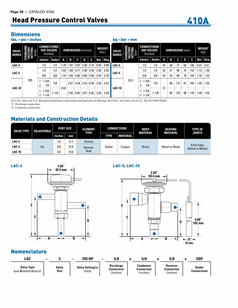
Page 36 — CATALOG 410A
410A Head Pressure Control Valves
Dimensionslbs. n psi n inches kg n bar n mm
VALVE SERIES
STA
ND
ARD
FACT
ORY
SETT
ING
(psi
g)
CONNECTIONSODF SOLDER
(Inches)DIMENSIONS (Inches) WEIGHT
(lbs .)
Inlet(s) Outlet A B C D E Net Ship
LAC-4
295
1/2 1/2 1 .78 1 .87 3 .02 2 .38 4 .73 0 .82 0 .90
LAC-51/2 1/2 1 .65 1 .60 3 .77 2 .99 5 .59 2 .50 2 .65
5/8 5/8 1 .74 1 .69 3 .86 3 .08 5 .68 2 .55 2 .70
LAC-10
Q
W
1-3/87/8
7/8
2 .82
2 .67 4 .39 3 .43 6 .49 3 .20 3 .42
Q
W
1-3/81-1/8
1-1/8 2 .56 4 .83 3 .87 6 .93 3 .28 3 .50
VALVE SERIES
STA
ND
ARD
FACT
ORY
SETT
ING
(bar
)
CONNECTIONSODF SOLDER
(Inches)DIMENSIONS (mm) WEIGHT
(kg)
Inlet(s) Outlet A B C D E Net Ship
LAC-4
20 .3
1/2 1/2 45 48 77 60 120 0 .37 0 .41
LAC-51/2 1/2 42 41 96 76 142 1 .13 1 .20
5/8 5/8 44 43 98 78 144 1 .16 1 .22
LAC-10
Q
W
1-3/87/8
7/8
72
68 112 87 165 1 .45 1 .55
Q
W
1-3/81-1/8
1-1/8 65 123 98 176 1 .49 1 .59
1.94”49.3 mm
A
E
C
B
D
E
C
A B .75”19 mm
D4.00”
102 mm
2.34”59.4 mm
LAC-4 LAC-5, LAC-10
Materials and Construction Details
VALVE TYPE ADJUSTABLEPORT SIZE ELEMENT
TYPECONNECTIONS BODY
MATERIALSEATING
MATERIALTYPE OFJOINTS
Inches mm TYPE MATERIAL
LAC-4
No
1/2 12 .7 Domed
Solder Copper Brass Metal .to .Metal Knife .Edge(Metal .to .Metal)LAC-5 5/8 15 .9 Remote
BulbLAC-10 3/4 19 .0
All LAC valves are U.L. Recognized and have a maximum rated pressure of 680 psig (46.9 bar). All valves are in U.L. file SA-5460-SFJQ2.Q Discharge connection.W Condenser connection.
LAC – 5 – 295 HP – 5/8 x 5/8 x 5/8 x ODF
Valve TypeLow .Ambient .Control
ValveSize
Valve Setting(s)(psig)
DischargeConnection
(Inches)
CondenserConnection
(Inches)
ReceiverConnection
(Inches)
SolderConnections
Nomenclature
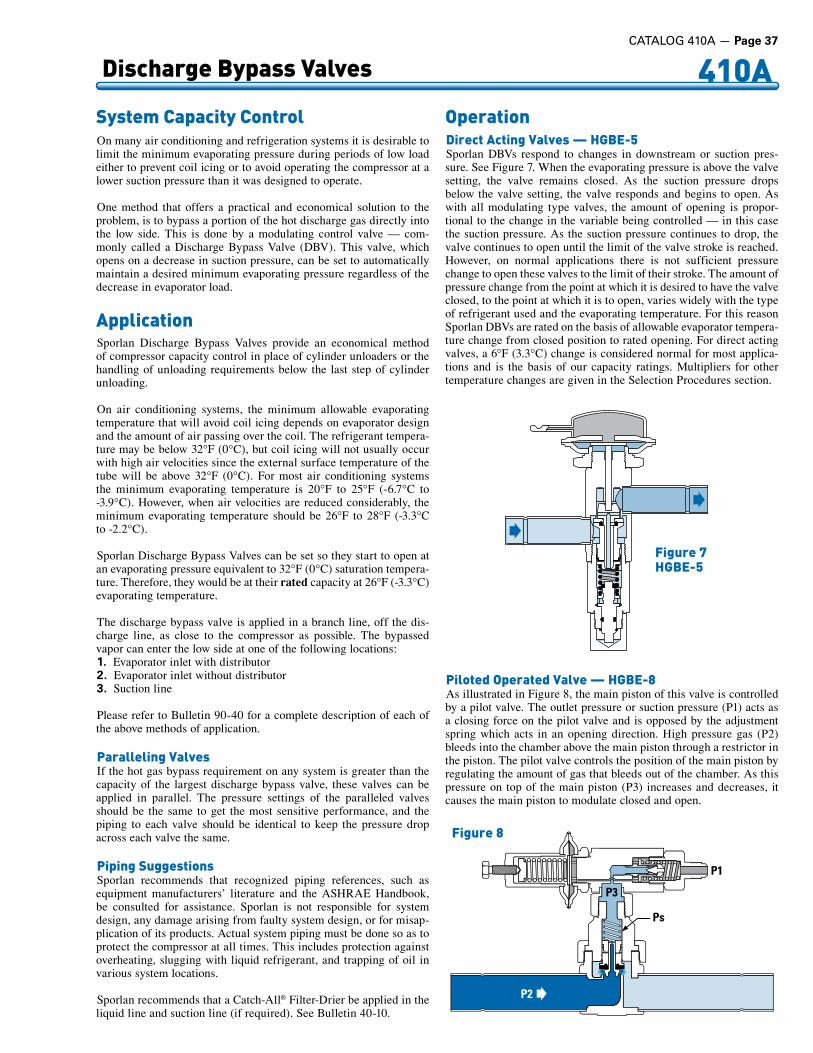
410A Discharge Bypass Valves
System Capacity ControlOn many air conditioning and refrigeration systems it is desirable to limit the minimum evaporating pressure during periods of low load either to prevent coil icing or to avoid operating the compressor at a lower suction pressure than it was designed to operate.
One method that offers a practical and economical solution to the problem, is to bypass a portion of the hot discharge gas directly into the low side. This is done by a modulating control valve — com-monly called a Discharge Bypass Valve (DBV). This valve, which opens on a decrease in suction pressure, can be set to automatically maintain a desired minimum evaporating pressure regardless of the decrease in evaporator load.
ApplicationSporlan Discharge Bypass Valves provide an economical method of compressor capacity control in place of cylinder unloaders or the handling of unloading requirements below the last step of cylinder unloading.
On air conditioning systems, the minimum allowable evaporating temperature that will avoid coil icing depends on evaporator design and the amount of air passing over the coil. The refrigerant tempera-ture may be below 32°F (0°C), but coil icing will not usually occur with high air velocities since the external surface temperature of the tube will be above 32°F (0°C). For most air conditioning systems the minimum evaporating temperature is 20°F to 25°F (-6.7°C to -3.9°C). However, when air velocities are reduced considerably, the minimum evaporating temperature should be 26°F to 28°F (-3.3°C to -2.2°C).
Sporlan Discharge Bypass Valves can be set so they start to open at an evaporating pressure equivalent to 32°F (0°C) saturation tempera-ture. Therefore, they would be at their rated capacity at 26°F (-3.3°C) evaporating temperature.
The discharge bypass valve is applied in a branch line, off the dis-charge line, as close to the compressor as possible. The bypassed vapor can enter the low side at one of the following locations:1. Evaporator inlet with distributor2. Evaporator inlet without distributor3. Suction line
Please refer to Bulletin 90-40 for a complete description of each of the above methods of application.
Paralleling ValvesIf the hot gas bypass requirement on any system is greater than the capacity of the largest discharge bypass valve, these valves can be applied in parallel. The pressure settings of the paralleled valves should be the same to get the most sensitive performance, and the piping to each valve should be identical to keep the pressure drop across each valve the same.
Piping SuggestionsSporlan recommends that recognized piping references, such as equipment manufacturers’ literature and the ASHRAE Handbook, be consulted for assistance. Sporlan is not responsible for system design, any damage arising from faulty system design, or for misap-plication of its products. Actual system piping must be done so as to protect the compressor at all times. This includes protection against overheating, slugging with liquid refrigerant, and trapping of oil in various system locations.
Sporlan recommends that a Catch-All® Filter-Drier be applied in the liquid line and suction line (if required). See Bulletin 40-10.
OperationDirect Acting Valves — HGBE-5Sporlan DBVs respond to changes in downstream or suction pres-sure. See Figure 7. When the evaporating pressure is above the valve setting, the valve remains closed. As the suction pressure drops below the valve setting, the valve responds and begins to open. As with all modulating type valves, the amount of opening is propor-tional to the change in the variable being controlled — in this case the suction pressure. As the suction pressure continues to drop, the valve continues to open until the limit of the valve stroke is reached. However, on normal applications there is not sufficient pressure change to open these valves to the limit of their stroke. The amount of pressure change from the point at which it is desired to have the valve closed, to the point at which it is to open, varies widely with the type of refrigerant used and the evaporating temperature. For this reason Sporlan DBVs are rated on the basis of allowable evaporator tempera-ture change from closed position to rated opening. For direct acting valves, a 6°F (3.3°C) change is considered normal for most applica-tions and is the basis of our capacity ratings. Multipliers for other temperature changes are given in the Selection Procedures section.
Piloted Operated Valve — HGBE-8As illustrated in Figure 8, the main piston of this valve is controlled by a pilot valve. The outlet pressure or suction pressure (P1) acts as a closing force on the pilot valve and is opposed by the adjustment spring which acts in an opening direction. High pressure gas (P2) bleeds into the chamber above the main piston through a restrictor in the piston. The pilot valve controls the position of the main piston by regulating the amount of gas that bleeds out of the chamber. As this pressure on top of the main piston (P3) increases and decreases, it causes the main piston to modulate closed and open.
Figure 7HGBE-5
P1
P2
Ps
P3
Fig ure 8
CATALOG 410A — Page 37

Page 38 — CATALOG 410A
410A Discharge Bypass Valves
As the suction pressure (P1) falls below the pilot valve’s setting, the pilot port modulates open. This bleeds refrigerant from the chamber above the piston through the pilot valve at a faster rate than it is entering, so the pressure decreases. As this pressure (P3) plus the pressure from the spring (Ps) falls below the inlet pressure (P2), the inlet pressure pushes the piston up, modulating the valve open. As the suction pressure rises above the setting of the pilot valve, the pilot port modulates closed. This allows pressure to build on top of the main piston. As this pressure (P3) approaches the inlet pressure (P2), the force combined with the force from the spring (Ps) pushes the piston down, modulating the valve closed.
Adjustment Ranges Pressure SettingAdjustable Spring Heads on Direct Acting ValvesThe adjustable type utilizes a spring assembly which can be fixed at the desired pressure setting (opening pressure). This setting will not be affected by other factors such as ambient or hot gas temperatures. The HGBE-5 is available with an adjustment range of 95/115 psig
(6.6/7.93 bar). The standard factory setting for this valve is 105 psig (7.24 bar).
Pilot Operated ValvesThe HGBE-8 is adjustable from 75 to 150 psi (5.2 to 10.3 bar). The standard factory setting is 120 psig (8.27 bar). Adjustment is made by turning the adjustment screw on the pilot valve. Turning this screw clockwise will increase the valve’s setting and a counterclockwise rotation will decrease the valve’s setting.
Adjusting these valves can be complicated because the load must be varied during the setting procedure. The load on the system must be decreased to lower the suction pressure so that the valve can control. The valve should then be adjusted to maintain the desired pressure. The load on the system should then be increased to raise the suc-tion pressure above the valve setting to close the valve. Once this is accomplished, the valve setting can be checked by slowly decreasing the load until the discharge bypass valve begins to open (a hissing sound and/or an accompanying pressure rise at the outlet connection will indicate that the bypass valve has opened).
VALVETYPE
STANDARD COPPER
CONNECTIONSODF - Inches
PORT SIZE ADJUSTMENTRANGE BODY
MATERIALSEATING
MATERIAL
SOCKETDEPTH
EXTERNALEQUALIZER
ODFInches
NETWEIGHT
Inches mm psi bar Inches mm lbs. kg
HGB-53/8, .1/2, .5/8 1/2 13 95/115 6 .6/7 .93
Brass SyntheticMetal
0 .31 7 .9
1/4 1 .25 0 .570 .37 9 .4HGBE-5 0 .50 12 .7
HGB-87/8, .1-1/8 0 .43 11 75/150 5 .2/10 .3
0 .75 191/4 3 .0 1 .4
HGBE-8 0 .91 23
Specifications
Both the HGB-8 and HGBE-8 are U.L. Recognized valves. They have a maximum rated pressure of 700 psig (48.3 bar). Both valves are in U.L. file SA-5460-SFJQ2.n Maximum Fluid Temperature of 240°F (116°C).n Maximum Ambient Temperature of 120°F (48.9°C).
1.94”49.3 mm
3.12”79.2 mm
BA
IN
2.48”63.0 mm
3.50”88.9 mm
4.96”126 mm
1.84”46.7 mm1/4” ODF
ExternalEqualizerConnection
C
D
ODF SOLDERInches
Inches mmA B C D A B C D
3/8 1 .87 1 .78 0 .38 0 .31 47 .5 45 .2 9 .65 7 .9
1/2 2 .12 2 .03 0 .50 0 .37 53 .8 51 .6 12 .7 9 .4
5/8 2 .43 2 .34 0 .63 0 .50 61 .7 59 .4 16 .0 12 .7
Dimensions HGBE-5 Top View
Connections

410A Discharge Bypass Valves
Selection ProceduresThe selection of a discharge bypass valve, and the necessary com-panion devices, is simplified if complete system information is available. This will result in the most economical selection because the components will match the system requirements.
Besides the discharge bypass valve, a specific application may require a hot gas solenoid valve, an auxiliary side connection distributor or ASC adapter, and a desuperheating TEV with a companion liquid line solenoid valve. Once the type of application (review Application Section on page 37) is determined, the necessary valves can be selected from the information discussed in this section.
Discharge Bypass ValvesThe selection of a Sporlan Discharge Bypass Valve involves five basic items:1. Refrigerant – valve capacities vary considerably for different
refrigerants.2. Minimum allowable evaporating temperature at the
reduced load condition – depending on the system, this value must be set to prevent coil icing and/or compressor short cycling. For example, this may be 32°F to 34°F (0°C to 1.1°C) for a water chiller; 26°F to 28°F (-3.3°C to -2.2°C) for a normal air condition-ing system.
3. Compressor capacity (tons/kW) at minimum allow-able evaporating temperature – consult compressor capac-ity ratings for this value.
4. Minimum evaporator load (tons/kW) at which the system is to be operated – most systems are not required to operate down to zero load but this value will depend on the type of system. For example, most air conditioning systems only need to operate down to 15-25% of full load. However, air conditioning systems for data processing and “white” rooms, and most refrig-eration systems may be required to bypass to zero load conditions.
5. Condensing temperature when minimum load exists – since the capacity ratings of the bypass valves are a function of condensing temperature, it is vital that proper head pressure is maintained, especially during low load operation. As the capacity table indicates, a condensing temperature of 80°F (27°C) is con-sidered the minimum allowable for satisfactory system operation. See Bulletin 90-30 for information on Sporlan’s Head Pressure Control Valves.
The discharge bypass valve must be selected to handle the difference between items 3 and 4 above. If the minimum evaporator load (item 4) is zero, the hot gas bypass requirement is simply the compressor capacity at the minimum allowable evaporating temperature (item 3). The following discussion on Capacity Ratings, and the example, show how these factors affect a selection on a typical air conditioning system.
Capacity Ratings – As the Discharge Bypass Valve Capacity Table indicates, valve ratings are dependent on the evaporating and condensing temperature at the reduced load condition and the refrigerant used. Therefore, once this information and the hot gas bypass requirement in tons/kW is determined, a discharge bypass valve can be selected.
As the capacity table heading indicates, these are valve capacities, not the system capacity on which the valve is applied. The ratings are the sum of the hot gas bypassed and the liquid refrigerant for desuperheat-ing, regardless of whether the liquid is fed through the system TEV or the auxiliary desuperheating TEV. The capacities are based on an evaporator temperature change of 6°F (3.3°C) from a closed position to the rated opening. This is a nominal rating value based on years of application experience. Since a discharge bypass valve is actually a pressure regulating valve, it should be pointed out that the capacity ratings based on a 6°F (3.3°C) evaporator temperature change takes into account that a 6°F (3.3°C) change @ 40°F (4.4°C) on R-410A is a 14.2 psi (0.98 bar) change. The 6°F (3.3°C) nominal change is
Dimensions HGBE-8 Externally Equalized HGB-8 Internally Equalized
3.00”76.2 mm
0.58” 15 mm
1.97”50.0 mm
4.57”116 mm
4.66”118 mm
4.66”118 mm
3.00”76.2 mm
0.58” 15 mm
1.97”50.0 mm
4.57”116 mm
4.66”118 mm
4.66”118 mm
Capacity MultipliersFor Evaporator Temperature Changes Other Than 6°F (3.3°C) Nominal ChangeTons n psi n °F kW n bar n °C
EVAPORATORTEMPERATURE
CHANGE °F
EVAPORATOR TEMPERATURE °F
40 26 20
2 0 .45 0 .40 0 .38
4 0 .82 0 .78 0 .76
8 1 .08 1 .11 1 .13
10 1 .11 1 .17 1 .20
EVAPORATORTEMPERATURE
CHANGE °C
EVAPORATOR TEMPERATURE °C
5 -3 -10
1 0 .41 0 .35 0 .312 0 .77 0 .72 0 .673 0 .96 0 .95 0 .944 1 .05 1 .08 1 .105 1 .09 1 .14 1 .206 1 .11 1 .18 1 .25
CATALOG 410A — Page 39
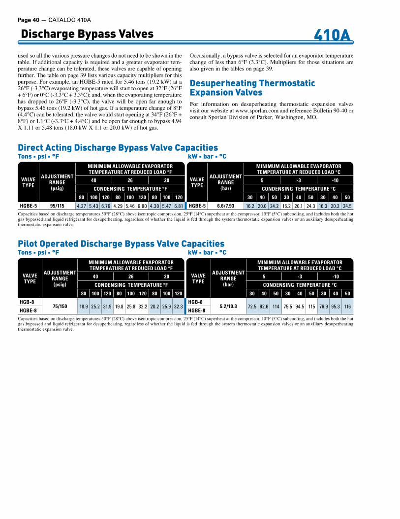
Page 40 — CATALOG 410A
410ADischarge Bypass Valves
VALVETYPE
ADJUSTMENT RANGE(psig)
MINIMUM ALLOWABLE EVAPORATORTEMPERATURE AT REDUCED LOAD °F
40 26 20
CONDENSING TEMPERATURE °F
80 100 120 80 100 120 80 100 120
HGBE-5 95/115 4 .27 5 .43 6 .76 4 .29 5 .46 6 .80 4 .30 5 .47 6 .81
Direct Acting Discharge Bypass Valve CapacitiesTons n psi n °F kW n bar n °C
VALVETYPE
ADJUSTMENT RANGE
(bar)
MINIMUM ALLOWABLE EVAPORATORTEMPERATURE AT REDUCED LOAD °C
5 -3 -10
CONDENSING TEMPERATURE °C
30 40 50 30 40 50 30 40 50
HGBE-5 6.6/7.93 16 .2 20 .0 24 .2 16 .2 20 .1 24 .3 16 .3 20 .2 24 .5Capacities based on discharge temperatures 50°F (28°C) above isentropic compression, 25°F (14°C) superheat at the compressor, 10°F (5°C) subcooling, and includes both the hot gas bypassed and liquid refrigerant for desuperheating, regardless of whether the liquid is fed through the system thermostatic expansion valves or an auxiliary desuperheating thermostatic expansion valve.
VALVETYPE
ADJUSTMENT RANGE(psig)
MINIMUM ALLOWABLE EVAPORATORTEMPERATURE AT REDUCED LOAD °F
40 26 20
CONDENSING TEMPERATURE °F
80 100 120 80 100 120 80 100 120
HGB-875/150 18 .9 25 .2 31 .9 19 .8 25 .8 32 .2 20 .2 25 .9 32 .3
HGBE-8
Pilot Operated Discharge Bypass Valve CapacitiesTons n psi n °F kW n bar n °C
Capacities based on discharge temperatures 50°F (28°C) above isentropic compression, 25°F (14°C) superheat at the compressor, 10°F (5°C) subcooling, and includes both the hot gas bypassed and liquid refrigerant for desuperheating, regardless of whether the liquid is fed through the system thermostatic expansion valves or an auxiliary desuperheating thermostatic expansion valve.
VALVETYPE
ADJUSTMENT RANGE
(bar)
MINIMUM ALLOWABLE EVAPORATORTEMPERATURE AT REDUCED LOAD °C
5 -3 -10
CONDENSING TEMPERATURE °C
30 40 50 30 40 50 30 40 50
HGB-85.2/10.3 72 .5 92 .6 114 75 .5 94 .5 115 76 .9 95 .3 116
HGBE-8
used so all the various pressure changes do not need to be shown in the table. If additional capacity is required and a greater evaporator tem-perature change can be tolerated, these valves are capable of opening further. The table on page 39 lists various capacity multipliers for this purpose. For example, an HGBE-5 rated for 5.46 tons (19.2 kW) at a 26°F (-3.3°C) evaporating temperature will start to open at 32°F (26°F + 6°F) or 0°C (-3.3°C + 3.3°C); and, when the evaporating temperature has dropped to 26°F (-3.3°C), the valve will be open far enough to bypass 5.46 tons (19.2 kW) of hot gas. If a temperature change of 8°F (4.4°C) can be tolerated, the valve would start opening at 34°F (26°F + 8°F) or 1.1°C (-3.3°C + 4.4°C) and be open far enough to bypass 4.94 X 1.11 or 5.48 tons (18.0 kW X 1.1 or 20.0 kW) of hot gas.
Occasionally, a bypass valve is selected for an evaporator temperature change of less than 6°F (3.3°C). Multipliers for those situations are also given in the tables on page 39.
Desuperheating ThermostaticExpansion ValvesFor information on desuperheating thermostatic expansion valves visit our website at www.sporlan.com and reference Bulletin 90-40 or consult Sporlan Division of Parker, Washington, MO.

CATALOG 410A — Page 41
410A AlsoCompatiblewithRefrigerants12,22,134a,404A,407C,502,507,744
Electric Expansion ValvesSporlan Electric Expansion Valves (EEVs) are currently available in nominal R-410A capacities from 2.5 to 210 tons (8.9 to 735 kW). Therefore, they are applicable on all the same types of systems found in the air conditioning and refrigeration industry as thermostatic expansion valves.
Sporlan electric valves are designed for compatibility with all current halocarbon refrigerants, including CFCs, HCFCs and HFCs, R-410A and R-744. Specific system conditions will dictate which product is necessary to control the application. Details can be reviewed with the Sporlan Sales Engineer.
The SER, SERI and SEH are Electronically Operated Step Motor flow control valves, intended for the precise control of liquid refriger-ant flow. Synchronized signals to the motor provide discrete angu-lar movement, which translates into precise linear positioning of the valve piston. Valve pistons and ports are uniquely characterized, pro-
viding improved flow resolution and performance. The SER and SEH valves are easily interfaced with microprocessor based controllers, including Sporlan supplied controllers.
All Sporlan SER and SERI valves are rated for at least 700 psig (48 bar) MRP. The SEH(I) 175 is rated for 620 psig (43 bar) MRP.
VALVETYPE INLET – Inches (ODF) OUTLET – Inches (ODF) CONFIGURATION
CABLE LENGTHFeet Meters
SER-B* 1/4, .3/8 3/8, .1/2, .5/8 Angle 10, .20 3, .6SER-C* 1/4, .3/8 3/8, .1/2, .5/8 Angle 10, .20 3, .6SER-D* 3/8, .1/2, .5/8 1/2, .5/8, .7/8, .1-1/8 Straight .Through .Offset 10, .20 3, .6SERI-G* 5/8, .7/8 1/2, .5/8, .7/8, .1-1/8
Angle .orStraight .Through .Offset
10, .40 3, .12SERI-J* 7/8, .1-1/8 7/8, .1-1/8, .1-3/8 10, .40 3, .12SERI-K** 1-1/8 7/8, .1-1/8, .1-3/8, .1-5/8 10, .40 3, .12SERI-L** 1-1/8, .1-3/8 1-1/8, .1-3/8, .1-5/8 10, .40 3, .12SEH(I) 175 1-1/8, .1-3/8, .1-5/8 2-1/8 Straight .Through .Offset 10, .20, .30, .40 3, .6, .9, .12
For complete information see your Sporlan Wholesaler, our website at www.sporlan.com, or write Sporlan and request Bulletin 100-20.
Specifications
Electronic Temperature Control Systems
SERI-JS
SER-C
SERI-K
VALVETYPE
NOMINAL CAPACITY
(Tons)
40°F 20°F 0°F PRESSURE DROP ACROSS VALVE (psi)
80 120 160 200 240 280 320 360 80 120 160 200 240 280 320 360 80 120 160 200 240 280 320 360SER-B 2 .5 1 .78 2 .19 2 .52 2 .82 3 .09 3 .34 3 .57 3 .79 1 .75 2 .14 2 .47 2 .76 3 .02 3 .27 3 .49 3 .70 1 .70 2 .08 2 .40 2 .69 2 .94 3 .18 3 .40 3 .61SER-C 6 .8 4 .84 5 .93 6 .84 7 .65 8 .38 9 .05 9 .68 10 .3 4 .73 5 .80 6 .70 7 .49 8 .20 8 .86 9 .47 10 .0 4 .61 5 .65 6 .52 7 .29 7 .98 8 .62 9 .22 9 .78SER-D 14 9 .84 12 .1 13 .9 15 .6 17 .0 18 .4 19 .7 20 .9 9 .63 11 .8 13 .6 15 .2 16 .7 18 .0 19 .3 20 .4 9 .38 11 .5 13 .3 14 .8 16 .2 17 .5 18 .8 19 .9SERI-G 27 19 .1 23 .4 27 .0 30 .2 33 .1 35 .8 38 .3 40 .6 18 .7 22 .9 26 .4 29 .5 32 .3 34 .9 37 .3 39 .6 18 .1 22 .2 25 .6 28 .7 31 .4 33 .9 36 .3 38 .5SERI-J 49 34 .4 42 .2 48 .7 54 .4 59 .6 64 .4 68 .8 73 .0 33 .6 41 .1 47 .5 53 .1 58 .2 62 .8 67 .2 71 .2 32 .6 40 .0 46 .1 51 .6 56 .5 61 .0 65 .2 69 .2SERI-K 88 62 .4 76 .4 88 .2 98 .7 108 117 125 132 60 .9 74 .6 86 .1 96 .3 105 114 122 129 59 .1 72 .4 83 .6 93 .5 102 111 118 125SERI-L 119 83 .8 103 119 133 145 157 168 178 82 .0 100 116 130 142 153 164 174 79 .9 97 .8 113 126 138 149 160 169SEH(I) 175 210 148 182 210 234 257 277 296 314 145 177 204 229 250 271 289 307 140 172 199 222 243 263 281 298
VALVETYPE
NOMINAL CAPACITY
(kW)
5°C -10°C -20°C PRESSURE DROP ACROSS VALVE (bar)
5 8 11 14 17 20 23 26 5 8 11 14 17 20 23 26 5 8 11 14 17 20 23 26SER-B 8 .9 5 .98 7 .56 8 .86 10 .0 11 .0 12 .0 12 .8 13 .6 5 .85 7 .40 8 .67 9 .78 10 .8 11 .7 12 .5 13 .3 5 .69 7 .20 8 .44 9 .53 10 .5 11 .4 12 .2 13 .0SER-C 24 16 .2 20 .5 24 .0 27 .1 29 .9 32 .4 34 .8 36 .9 15 .9 20 .1 23 .5 26 .5 29 .2 31 .7 34 .0 36 .2 15 .4 19 .5 22 .9 25 .8 28 .5 30 .9 33 .1 35 .2SER-D 49 33 .0 41 .7 48 .9 55 .1 60 .8 65 .9 70 .7 75 .2 32 .3 40 .8 47 .8 54 .0 59 .5 64 .5 69 .2 73 .5 31 .4 39 .7 46 .6 52 .5 57 .9 62 .8 67 .3 71 .6SERI-G 95 63 .9 80 .8 95 .2 107 118 128 137 145 61 .8 78 .1 91 .8 104 114 123 133 141 60 .1 76 .1 89 .3 100 111 120 129 137SERI-J 171 115 145 171 192 212 230 247 263 111 140 165 186 205 223 238 253 108 137 161 181 200 217 232 247SERI-K 309 208 264 309 349 384 417 447 475 201 255 299 337 371 403 433 460 196 248 291 328 361 392 421 447SERI-L 416 281 355 416 470 518 561 602 640 275 347 407 460 506 549 589 626 267 338 397 447 493 535 573 610SEH(I) 175 735 495 626 735 829 913 990 1062 1129 479 605 710 801 883 957 1027 1091 466 589 691 779 859 932 999 1062
Capacities Tons n psi n °F
kW n bar n °C
*Suitable for bi-directional applications.**Bi-sealing, reduced flow in reverse direction.
CORRECTION FACTOR, CF LIQUID TEMPERATURE °F0 10 20 30 40 50 60 70 80 90 100 110 120 130 140
1 .79 1 .71 1 .63 1 .55 1 .47 1 .40 1 .32 1 .24 1 .16 1 .08 1 .00 0 .92 0 .83 0 .73 0 .62
CORRECTION FACTOR, CF LIQUID TEMPERATURE °C-18 -12 -7 -1 4 10 16 21 27 32 38 43 49 54 601 .79 1 .71 1 .63 1 .55 1 .47 1 .40 1 .32 1 .24 1 .16 1 .08 1 .00 0 .92 0 .83 0 .73 0 .62

Page 42 — CATALOG 410A
410A AlsoCompatiblewithRefrigerants12,22,134a,404A,407C,502,507,744
SpecificationsTYPE CONNECTIONS
ODF SOLDER – Inches CONFIGURATIONCABLE LENGTH
CABLE ENDSFeet Meters
CDS-4 1/2, .5/8, .7/8 Straight .Through
1020
36 S-Stripped .and .Tinned
CDS-7 5/8, .7/8, .1-1/8, .1-3/8 Straight .ThroughCDS-9 5/8, .7/8, .1-1/8, .1-3/8 Straight .ThroughCDS-16 1-3/8 AngleCDS-17 1-3/8, .1-5/8, .2-1/8 Straight .Through
For complete information see your Sporlan Wholesaler, our website at www.sporlan.com, or write Sporlan and request Bulletin 100-40.
Electronic Temperature Control Systems
The CDS valves are designed for more precise and energy efficient control of tempera-tures in evaporators. Proper temperature is obtained by regulating refrigerant flow in the evaporator in response to signals generated by an elec-tronic controller and sensor combination. The valves are built around balanced ports, which allows input power of less than 4 watts, less than one quarter of the power used by older heat motor and analog designs. When not actively stepping, power to the motor is removed for further energy savings. The step motors used are standard 12-volt DC bipolar designs, which in concert with the integral gear reduc-tion, give the valves unsurpassed accuracy and repeatability over the entire operating range. Since the valves are powered from an exter-nal controller, no pilot lines or high to low side bleeds are required.
The properly applied CDS valve and controller can replace standard mechanical evaporator pressure regulators (EPR), suction stop sole-noid valves, and conventional thermostats.
CDS-4, CDS-7, CDS-9 and CDS-17 valves may be applied as heat reclaim, head pressure control, or liquid line differential valves for R-410A. Contact Sporlan for more information. All Sporlan CDS valves are rated at least 680 psig (47 bar) MRP.
Due to the step motor design, the CDS series are the first evaporator control valves that may be sized to contribute NO additional pressure drop to the suction line.
Simplified cartridge design allows all moving parts to be replaced as a unit. Only the valve body is left in the line. This will allow mainte-nance or repair without unsweating the entire valve.
Electric Evaporator Control ValvesCDS-4, -7, -9, -16 and -17
CDS-7
Flow Capacity - Suction VaporTons n psi n °F kW n bar n °C
TYPE EVAPORATORTEMP. °F
PRESSURE DROP ACROSS VALVE – psi0.5 1 3 5 10
CDS-4
. 40 1 .37 1 .93 3 .30 4 .23 5 .94 . 20 1 .13 1 .59 2 .73 3 .50 4 .97 . 0 0 .92 1 .29 2 .22 2 .85 3 .92 . -20 0 .74 1 .03 1 .77 2 .24 2 .97
CDS-7
. 40 3 .87 5 .35 8 .95 11 .4 15 .7 . 20 3 .22 4 .46 7 .45 9 .47 13 .6 . 0 2 .64 3 .65 6 .11 7 .76 10 .5 . -20 2 .12 2 .94 4 .91 6 .08 7 .75
CDS-9
. 40 5 .78 8 .02 13 .5 17 .2 23 .9 . 20 4 .80 6 .67 11 .2 14 .3 20 .5 . 0 3 .92 5 .45 9 .18 11 .7 16 .1 . -20 3 .15 4 .37 7 .36 9 .23 12 .2
CDS-16
. 40 9 .90 13 .8 23 .4 30 .0 41 .8 . 20 8 .21 11 .5 19 .4 24 .8 34 .7 . 0 6 .70 9 .34 15 .9 20 .3 26 .7 . -20 5 .36 7 .48 12 .7 15 .5 19 .3
CDS-17
. 40 10 .3 14 .4 24 .3 31 .0 43 .1 . 20 8 .58 11 .9 20 .2 25 .7 37 .0 . 0 7 .01 9 .75 16 .5 21 .0 29 .1 . -20 5 .62 7 .82 13 .2 16 .7 21 .9
TYPE EVAPORATORTEMP. °C
PRESSURE DROP ACROSS VALVE – bar0.03 0.06 0.2 0.4 0.7
CDS-4
. 5 4 .55 6 .39 11 .5 16 .2 21 .3 . -10 3 .51 4 .93 8 .88 12 .5 16 .4 . -20 2 .90 4 .07 7 .34 10 .3 13 .2 . -30 2 .36 3 .31 5 .97 8 .17 10 .2
CDS-7
. 5 12 .9 17 .8 31 .2 43 .2 56 .2 . -10 10 .0 13 .9 24 .3 33 .7 44 .7 . -20 8 .34 11 .5 20 .3 28 .3 35 .2 . -30 6 .84 9 .46 16 .6 22 .0 26 .4
CDS-9
. 5 19 .2 26 .7 47 .2 65 .6 85 .5 . -10 14 .9 20 .7 36 .7 50 .9 67 .8 . -20 12 .4 17 .2 30 .5 42 .6 54 .2 . -30 10 .1 14 .1 24 .9 33 .6 41 .8
CDS-16
. 5 32 .9 45 .9 81 .8 114 .2 149 .4 . -10 25 .5 35 .5 63 .4 88 .4 113 .9 . -20 21 .1 29 .4 52 .5 72 .3 88 .8 . -30 17 .2 24 .0 42 .9 55 .8 65 .6
CDS-17
. 5 34 .3 47 .8 84 .8 118 .0 154 .1 . -10 26 .6 37 .1 65 .8 91 .6 122 .4 . -20 22 .1 30 .8 54 .6 77 .1 97 .5 . -30 18 .1 25 .1 44 .6 60 .6 74 .9
Flow Capacity - LiquidTons n psi n °F kW n bar n °C
TYPE CvPRESSURE DROP ACROSS VALVE – psi
0.5 1 3 5 10CDS-4 2 .88 7 .65 10 .7 18 .4 23 .6 33 .1CDS-7 7 .28 20 .0 27 .7 46 .3 58 .8 81 .3CDS-9 11 .2 30 .5 42 .4 71 .4 91 .0 126CDS-16 17 .9 53 .6 74 .7 127 162 226CDS-17 20 .4 55 .1 76 .7 130 165 230
TYPE KvPRESSURE DROP ACROSS VALVE – bar
0.03 0.06 0.2 0.4 0.7CDS-4 2 .49 25 .0 35 .1 63 .2 88 .7 117CDS-7 6 .30 65 .5 90 .6 159 220 286CDS-9 9 .72 99 .9 139 246 341 445CDS-16 15 .5 175 244 436 608 796CDS-17 17 .6 180 251 446 620 810
CORRECTION FACTOR, CF LIQUID TEMPERATURE °F0 10 20 30 40 50 60 70 80 90 100
1 .28 1 .24 1 .19 1 .14 1 .10 1 .05 1 .00 0 .95 0 .90 0 .85 0 .80
CORRECTION FACTOR, CF LIQUID TEMPERATURE °C-18 -12 -7 -1 4 10 16 21 27 32 381 .28 1 .24 1 .19 1 .14 1 .10 1 .05 1 .00 0 .95 0 .90 0 .85 0 .80
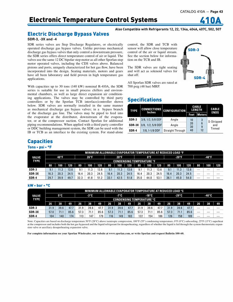
CATALOG 410A — Page 43
410A AlsoCompatiblewithRefrigerants12,22,134a,404A,407C,502,507
VALVETYPE
MINIMUM ALLOWABLE EVAPORATOR TEMPERATURE AT REDUCED LOAD °F40°F 26°F 20°F 0°F -20°F -40°F
CONDENSING TEMPERATURE °F80 100 120 80 100 120 80 100 120 80 100 120 80 100 120 80 100 120
SDR-3 9 .1 11 .3 13 .6 9 .1 11 .3 13 .6 9 .1 11 .3 13 .6 9 .1 11 .3 13 .6 9 .1 11 .3 13 .6 — — —SDR-3X 16 .3 20 .3 24 .5 16 .4 20 .3 24 .5 16 .4 20 .3 24 .5 16 .4 20 .3 24 .5 16 .4 20 .3 24 .5 — — —SDR-4 29 .7 39 .9 49 .7 32 .3 41 .8 51 .2 33 .1 42 .5 51 .8 35 .0 44 .0 53 .1 36 .1 45 .0 54 .0 — — —
Note: Capacities are based on discharge temperature 50°F (28°C) above isentropic compression, 100°F (55°) condensing temperature, 0°F (0°C) subcooling, 25°F (13°C) superheat at the compressor and includes both the hot gas bypassed and the liquid refrigerant for desuperheating, regardless of whether the liquid is fed through the system thermostatic expan-sion valve or auxiliary desuperheating expansion valve.
For complete information see your Sporlan Wholesaler, our website at www.sporlan.com, or write Sporlan and request Bulletin 100-60.
SDR series valves are Step Discharge Regulators, or electrically operated discharge gas bypass valves. Unlike previous mechanical discharge gas bypass valves that only control a downstream pressure, the SDR series offers direct temperature control of air or liquid. The valves use the same 12 DC bipolar step motor as all other Sporlan step motor operated valves, including the CDS valves above. Balanced pistons and ports, uniquely characterized for hot gas flow, have been incorporated into the design. Seating materials, motors and gears have all been laboratory and field proven in high temperature gas applications.
With capacities up to 30 tons (140 kW) nominal R-410A, the SDR series is suitable for use in small process chillers and environ-mental chambers, as well as large direct expansion air condition-ing applications. The valves may be controlled by third party controllers or by the Sporlan TCB interface/controller shown below. SDR valves are normally installed in the same manner as mechanical discharge gas bypass valves; in a bypass branch of the discharge gas line. The valves may be piped to feed into the evaporator at the distributor, downstream of the evapora-tor, or at the compressor suction. Contact Sporlan for additional piping recommendations. When applied with a third party controller or DDC building management system, the SDR can be used with the IB or TCB as an interface to the existing system. For stand-alone
control, the SDR and TCB with sensor will allow close temperature control of the air or liquid stream. See the section below for informa-tion on the TCB and IB.
The SDR valves are tight seating and will act as solenoid valves for shut off.
All Sporlan SDR valves are rated at 700 psig (48 bar) MRP.
Specifications
Electronic Temperature Control Systems
Electric Discharge Bypass ValvesSDR-3, -3X and -4
TYPE CONNECTIONSInches CONFIGURATION
CABLE LENGTH CABLE
ENDSFeet Meters
SDR-3 3/8, .1/2, .5/8 .ODF Angle 10203040
369
12
S-Stripped .and
TinnedSDR-3X 3/8, . .1/2, .5/8 .ODF Angle
SDR-4 7/8, .1-1/8 .ODF Straight .Through
CapacitiesTons n psi n °F
VALVETYPE
MINIMUM ALLOWABLE EVAPORATOR TEMPERATURE AT REDUCED LOAD °C5°C -3°C -7°C -18°C -29°C -40°C
CONDENSING TEMPERATURE °C26 38 49 26 38 49 26 38 49 26 38 49 26 38 49 26 38 49
SDR-3 31 .9 39 .6 47 .7 31 .9 39 .6 47 .7 31 .9 39 .6 47 .7 31 .9 39 .6 47 .7 31 .9 39 .6 47 .7 — — —SDR-3X 57 .0 71 .1 85 .6 57 .3 71 .1 85 .6 57 .3 71 .1 85 .6 57 .3 71 .1 85 .6 57 .3 71 .1 85 .6 — — —SDR-4 104 140 174 113 147 179 116 149 . . .183 122 154 186 126 158 189 — — —
kW n bar n °C
SDR-4
SDR-3

410A AlsoCompatiblewithRefrigerants12,22,134a,404A,407C,502,507
Page 44 — CATALOG 410A
Sporlan offers a variety of controllers for use in refrigeration and air conditioning systems. Applications include self-contained food ser-vice equipment, cold rooms and chillers. With over 80 different mod-els, Sporlan can satisfy almost any customer requirement.
Small, standalone controllers include the compact Kelvin and larger Superheat and Refrigeration controllers. All are designed to provide true pressure/temperature superheat control of any system using Sporlan Electric Expansion Valves (EEVs). Chiller controllers offer true pressure/temperature superheat control for two Sporlan EEVs and are available in Fahrenheit/psi or Celsius/Bar versions.
Sporlan offers many purpose built controllers, such as subcoolers for supermarket refrigeration, as well as head pressure, temperature only and pressure only.
Cold rooms can be controlled with RCS, which has onboard remote communication, and master-slave settings for defrost control. In-cluded real time clocks allow defrost initialization times to be set precisely and relays allow control of fans, solenoids, alarms and compressors. Many of the controllers can be customized for specific needs, or supplied in an enclosure, please contact Product Manager, Electronic Products, Sporlan Division.
CONTROLLER PACKAGES DISPLAY COMMUNICATION RELAYS INPUTS* VALVES
Kelvin Optional RS-485 One 1 .Press, .2 .Temp . 1 .SER, .SEI, .ESX .or .SEHIRCS 3 .Alphanumeric RS-485 Four 1 .Press, .4 .Temp . 1 .SER, .SEI, .ESX .or .SEHISubcooler 2 .Numeric None None 1 .Press, .2 .Temp . 1 .SER, .SEI, .ESX .or .SEHIChiller 2 .Numeric None Three 1 .Press, .4 .Temp . 2 .SER, .SEI, .ESX .or .SEHIChiller European 2 .Numeric .(C°/Bar) None Three 1 .Press, .4 .Temp . 2 .SER, .SEI, .ESX .or .SEHIPressure 2 .Numeric None None 1 .Press 1 .CDS .or .1 .SDRDual Pressure Control 2 .Numeric None None 2 .Press 2 .CDS .or .2 .SDR .or .1 .of .eachTemperature Control 2 .Numeric None None 1 .Temperature 1 .CDS .or .1 .SDRDual Temp. Control 2 .Numeric None None 2 .Temperature 2 .CDS .or .2 .SDR .or .1 .of .eachSuperheat 2 .Numeric None None 1 .Press, .2 .Temp . 1 .SER, .SEI, .ESX, .or .SEHISuperheat Low Temp. 2 .Numeric None None 1 .Press, .2 .Temp . 1 .SER, .SEI, .ESX, .or .SEHIRefrigeration 2 .Numeric None None 1 .Press, .2 .Temp . 1 .SER, .SEI, .ESX, .or .SEHI
SELF CONTAINED EQUIPMENT
Unistat – Med. Temp. Optional None One Temperature** N/AUnistat – Low Temp. Optional None Two Defrost** N/AOmnistat – Low Temp. 3 .Digit RS .485 .Optional One Defrost, .Product, .Digital** N/AOmnistat – Med. Temp. 3 .Digit RS .485 .Optional Three Defrost, .Product, .Digital** N/A
* See accessories page 45, only Sporlan approved sensors may be used.** All products control temperature, other functions not available on all models.
Kelvin RCS Chiller
Electronic Temperature Control Systems
Controller Packages
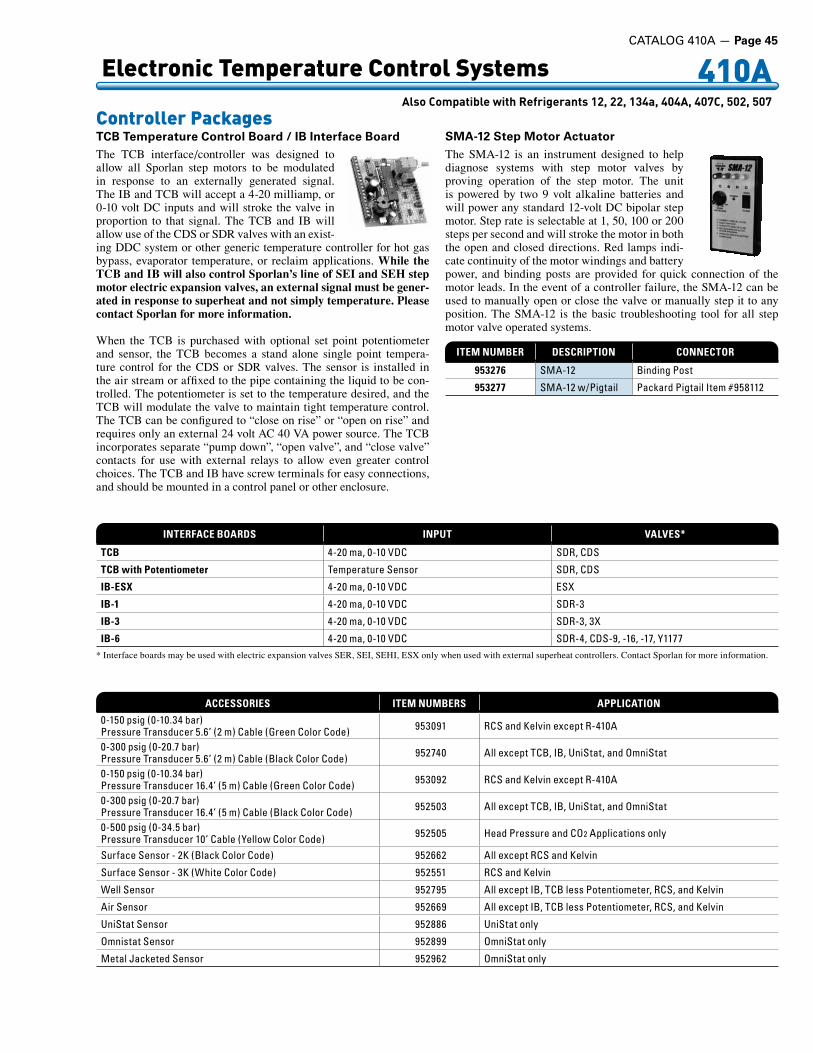
CATALOG 410A — Page 45
410A AlsoCompatiblewithRefrigerants12,22,134a,404A,407C,502,507
ACCESSORIES ITEM NUMBERS APPLICATION
0-150 .psig .(0-10 .34 .bar)Pressure .Transducer .5 .6’ .(2 .m) .Cable .(Green .Color .Code) . 953091 RCS .and .Kelvin .except .R-410A
0-300 .psig .(0-20 .7 .bar)Pressure .Transducer .5 .6’ .(2 .m) .Cable .(Black .Color .Code) 952740 All .except .TCB, .IB, .UniStat, .and .OmniStat
0-150 .psig .(0-10 .34 .bar)Pressure .Transducer .16 .4’ .(5 .m) .Cable .(Green .Color .Code) 953092 RCS .and .Kelvin .except .R-410A
0-300 .psig .(0-20 .7 .bar)Pressure .Transducer .16 .4’ .(5 .m) .Cable .(Black .Color .Code) 952503 All .except .TCB, .IB, .UniStat, .and .OmniStat
0-500 .psig .(0-34 .5 .bar)Pressure .Transducer .10’ .Cable .(Yellow .Color .Code) 952505 Head .Pressure .and .CO2 .Applications .only
Surface .Sensor .- .2K .(Black .Color .Code) 952662 All .except .RCS .and .Kelvin
Surface .Sensor .- .3K .(White .Color .Code) 952551 RCS .and .Kelvin
Well .Sensor 952795 All .except .IB, .TCB .less .Potentiometer, .RCS, .and .Kelvin
Air .Sensor 952669 All .except .IB, .TCB .less .Potentiometer, .RCS, .and .Kelvin
UniStat .Sensor 952886 UniStat .only
Omnistat .Sensor 952899 OmniStat .only
Metal .Jacketed .Sensor 952962 OmniStat .only
The TCB interface/controller was designed to allow all Sporlan step motors to be modulated in response to an externally generated signal. The IB and TCB will accept a 4-20 milliamp, or 0-10 volt DC inputs and will stroke the valve in proportion to that signal. The TCB and IB will allow use of the CDS or SDR valves with an exist-ing DDC system or other generic temperature controller for hot gas bypass, evaporator temperature, or reclaim applications. While the TCB and IB will also control Sporlan’s line of SEI and SEH step motor electric expansion valves, an external signal must be gener-ated in response to superheat and not simply temperature. Please contact Sporlan for more information.
When the TCB is purchased with optional set point potentiometer and sensor, the TCB becomes a stand alone single point tempera-ture control for the CDS or SDR valves. The sensor is installed in the air stream or affixed to the pipe containing the liquid to be con-trolled. The potentiometer is set to the temperature desired, and the TCB will modulate the valve to maintain tight temperature control. The TCB can be configured to “close on rise” or “open on rise” and requires only an external 24 volt AC 40 VA power source. The TCB incorporates separate “pump down”, “open valve”, and “close valve” contacts for use with external relays to allow even greater control choices. The TCB and IB have screw terminals for easy connections, and should be mounted in a control panel or other enclosure.
The SMA-12 is an instrument designed to help diagnose systems with step motor valves by proving operation of the step motor. The unit is powered by two 9 volt alkaline batteries and will power any standard 12-volt DC bipolar step motor. Step rate is selectable at 1, 50, 100 or 200 steps per second and will stroke the motor in both the open and closed directions. Red lamps indi-cate continuity of the motor windings and battery power, and binding posts are provided for quick connection of the motor leads. In the event of a controller failure, the SMA-12 can be used to manually open or close the valve or manually step it to any position. The SMA-12 is the basic troubleshooting tool for all step motor valve operated systems.
ITEM NUMBER DESCRIPTION CONNECTOR
953276 SMA-12 Binding .Post
953277 SMA-12 .w/Pigtail Packard .Pigtail .Item .#958112
INTERFACE BOARDS INPUT VALVES*
TCB 4-20 .ma, .0-10 .VDC SDR, .CDS
TCB with Potentiometer Temperature .Sensor SDR, .CDS
IB-ESX 4-20 .ma, .0-10 .VDC ESX
IB-1 4-20 .ma, .0-10 .VDC SDR-3
IB-3 4-20 .ma, .0-10 .VDC SDR-3, .3X
IB-6 4-20 .ma, .0-10 .VDC SDR-4, .CDS-9, .-16, .-17, .Y1177* Interface boards may be used with electric expansion valves SER, SEI, SEHI, ESX only when used with external superheat controllers. Contact Sporlan for more information.
Electronic Temperature Control Systems
Controller PackagesTCB Temperature Control Board / IB Interface Board SMA-12 Step Motor Actuator

Page 46 — CATALOG 410A
410A
At Sea Level
Pressure Temperature Chart
At Altitude – 5,000 ft. (1,524 m) Above Sea Level
Refrigerant 410A n Sporlan Code Z n Color Designation Rose (PMS 507)
OBTAIN SUCTION PRESSURE120 psig (8.27 barg) at bulb
Temperaturehere reads
52°F (11°C)40°F (4°C)12°F (7°C)SUPERHEAT
REFRIGERANT 410A
psig barg Temperature°F °C
. 5* -0 .17 -74 -59 . 4* -0 .14 -73 -58 . 3* -0 .10 -71 -57 . 2* -0 .07 -70 -57 . 1* -0 .03 -68 -56
0 0 .00 -67 -551 0 .07 -64 -532 0 .14 -62 -523 0 .21 -59 -514 0 .28 -57 -495 0 .34 -55 -486 0 .41 -53 -477 0 .48 -51 -468 0 .55 -49 -459 0 .62 -47 -44
10 0 .69 -45 -4311 0 .76 -44 -4212 0 .83 -42 -4113 0 .90 -40 -4014 0 .97 -39 -3915 1 .03 -37 -3816 1 .10 -36 -3817 1 .17 -34 -3718 1 .24 -33 -3619 1 .31 -32 -3520 1 .38 -30 -3521 1 .45 -29 -3422 1 .52 -28 -3323 1 .59 -27 -3324 1 .65 -25 -3225 1 .72 -24 -3126 1 .79 -23 -3127 1 .86 -22 -3028 1 .93 -21 -2929 2 .00 -20 -2930 2 .07 -19 -2831 2 .14 -18 -2832 2 .21 -17 -2733 2 .28 -16 -2634 2 .34 -15 -2635 2 .41 -14 -2536 2 .48 -13 -2537 2 .55 -12 -2438 2 .62 -11 -2439 2 .69 -10 -2340 2 .76 -9 -2342 2 .90 -7 -2244 3 .03 -5 -2146 3 .17 -4 -2048 3 .31 -2 -1950 3 .45 -1 -1852 3 .59 1 -1754 3 .72 2 -1656 3 .86 4 -1658 4 .00 5 -1560 4 .14 7 -1462 4 .27 8 -1364 4 .41 9 -1366 4 .55 11 -1268 4 .69 12 -11
psig barg Temperature°F °C
70 4 .83 13 -1072 4 .96 15 -1074 5 .10 16 -976 5 .24 17 -878 5 .38 18 -880 5 .52 19 -785 5 .86 22 -590 6 .21 25 -495 6 .55 28 -2
100 6 .89 30 -1105 7 .24 33 0110 7 .58 35 2115 7 .93 37 3120 8 .27 40 4125 8 .62 42 5130 8 .96 44 7135 9 .31 46 8140 9 .65 48 9145 10 .0 50 10150 10 .3 52 11155 10 .7 54 12160 11 .0 55 13165 11 .4 57 14170 11 .7 59 15175 12 .1 61 16180 12 .4 62 17185 12 .8 64 18190 13 .1 66 19195 13 .4 67 20200 13 .8 69 20205 14 .1 70 21210 14 .5 72 22220 15 .2 75 24230 15 .9 78 25240 16 .5 80 27250 17 .2 83 28260 17 .9 86 30275 19 .0 89 32290 20 .0 93 34305 21 .0 97 36320 22 .1 100 38335 23 .1 103 40350 24 .1 106 41365 25 .2 109 43380 26 .2 112 45400 27 .6 116 47420 29 .0 120 49440 30 .3 123 51460 31 .7 127 53480 33 .1 130 54500 34 .5 133 56520 35 .9 136 58540 37 .2 139 60560 38 .6 142 61580 40 .0 145 63600 41 .4 148 64625 43 .1 151 66650 44 .8 154 68675 46 .5 158 70
. 681c 46 .9 158 70
psig bargTemperature°F °C
70 4 .83 15 -972 4 .96 16 -974 5 .10 17 -876 5 .24 19 -778 5 .38 20 -780 5 .52 21 -685 5 .86 24 -590 6 .21 26 -395 6 .55 29 -2
100 6 .89 31 0105 7 .24 34 1110 7 .58 36 2115 7 .93 38 4120 8 .27 41 5125 8 .62 43 6130 8 .96 45 7135 9 .31 47 8140 9 .65 49 9145 10 .0 51 10150 10 .3 53 11155 10 .7 55 13160 11 .0 56 14165 11 .4 58 15170 11 .7 60 15175 12 .1 62 16180 12 .4 63 17185 12 .8 65 18190 13 .1 66 19195 13 .4 68 20200 13 .8 70 21205 14 .1 71 22210 14 .5 73 23220 15 .2 75 24230 15 .9 78 26240 16 .5 81 27250 17 .2 84 29260 17 .9 86 30275 19 .0 90 32290 20 .0 94 34305 21 .0 97 36320 22 .1 100 38335 23 .1 104 40350 24 .1 107 42365 25 .2 110 43380 26 .2 113 45400 27 .6 117 47420 29 .0 120 49440 30 .3 124 51460 31 .7 127 53480 33 .1 130 55500 34 .5 134 56520 35 .9 137 58540 37 .2 140 60560 38 .6 143 61580 40 .0 145 63600 41 .4 148 65625 43 .1 152 66650 44 .8 155 68675 46 .5 158 70
. 678c 46 .8 158 70
psig bargTemperature°F °C
. 5* -0 .17 -67 -55 . 4* -0 .14 -66 -54 . 3* -0 .10 -64 -53 . 2* -0 .07 -63 -53 . 1* -0 .03 -62 -52
0 0 .00 -61 -511 0 .07 -58 -502 0 .14 -56 -493 0 .21 -54 -484 0 .28 -52 -475 0 .34 -50 -456 0 .41 -48 -447 0 .48 -46 -438 0 .55 -44 -429 0 .62 -43 -42
10 0 .69 -41 -4111 0 .76 -40 -4012 0 .83 -38 -3913 0 .90 -37 -3814 0 .97 -35 -3715 1 .03 -34 -3616 1 .10 -32 -3617 1 .17 -31 -3518 1 .24 -30 -3419 1 .31 -28 -3420 1 .38 -27 -3321 1 .45 -26 -3222 1 .52 -25 -3223 1 .59 -24 -3124 1 .65 -22 -3025 1 .72 -21 -3026 1 .79 -20 -2927 1 .86 -19 -2828 1 .93 -18 -2829 2 .00 -17 -2730 2 .07 -16 -2731 2 .14 -15 -2632 2 .21 -14 -2633 2 .28 -13 -2534 2 .34 -12 -2535 2 .41 -11 -2436 2 .48 -10 -2437 2 .55 -9 -2338 2 .62 -9 -2339 2 .69 -8 -2240 2 .76 -7 -2242 2 .90 -5 -2144 3 .03 -3 -2046 3 .17 -2 -1948 3 .31 0 -1850 3 .45 1 -1752 3 .59 3 -1654 3 .72 4 -1556 3 .86 6 -1558 4 .00 7 -1460 4 .14 8 -1362 4 .27 10 -1264 4 .41 11 -1266 4 .55 12 -1168 4 .69 14 -10
* Includes inches of mercury below one atmosphere. c = critical point

CATALOG 410A — Page 47
OFFEROFSALE
The items described in this document and other documents and descriptions provided by Parker Hannifin Corporation, its subsidiaries and its authorized distributors (“Seller”) are hereby offered for sale at prices to be established by Seller. This offer and its acceptance by any customer (“Buyer”) shall be governed by all of the following Terms and Conditions. Buyer’s order for any item described in its document, when communicated to Seller verbally, or in writing, shall constitute acceptance of this offer. All goods or work described will be referred to as “Products”.
1. Terms and Conditions. Seller’s willingness to offer Products, or accept an order for Products, to or from Buyer is expressly conditioned on Buyer’s as-sent to these Terms and Conditions and to the terms and conditions found on-line at www.parker.com/saleterms/. Seller objects to any contrary or additional term or condition of Buyer’s order or any other docu-ment issued by Buyer.2. Price Adjustments; Payments. Prices stated on the reverse side or preceding pages of this document are valid for 30 days. After 30 days, Seller may change prices to reflect any increase in its costs resulting from state, federal or local legislation, price increases from its suppliers, or any change in the rate, charge, or classification of any carrier. The prices stated on the reverse or preceding pages of this document do not include any sales, use, or other taxes unless so stated specifically. Unless otherwise specified by Seller, all prices are F.O.B. Seller’s facility, and pay-ment is due 30 days from the date of invoice. After 30 days, Buyer shall pay interest on any unpaid invoices at the rate of 1.5% per month or the maximum allow-able rate under applicable law.3. Delivery Dates; Title and Risk; Shipment. All delivery dates are approximate and Seller shall not be responsible for any damages resulting from any delay. Regardless of the manner of shipment, title to any products and risk of loss or damage shall pass to Buyer upon tender to the carrier at Seller’s facility (i.e., when it’s on the truck, it’s yours). Unless otherwise stated, Seller may exercise its judgment in choosing the carrier and means of delivery. No deferment of shipment at Buyers’ request beyond the respec-tive dates indicated will be made except on terms that will indemnify, defend and hold Seller harmless against all loss and additional expense. Buyer shall be responsible for any additional shipping charges incurred by Seller due to Buyer’s changes in shipping, product specifications or in accordance with Section 13, herein.4. Warranty. Seller warrants that the Products sold hereunder shall be free from defects in material or workmanship for a period of twelve months from the date of delivery to Buyer or 2,000 hours of normal use, whichever occurs first. This warranty is made only to Buyer and does not extend to anyone to whom Products are sold after purchased from Seller. The prices charged for Seller’s products are based upon the exclusive limited warranty stated above, and upon the following disclaimer: DISCLAIMER OF WARRANTY: THIS WARRANTY COMPRISES THE SOLE AND ENTIRE WARRANTY PERTAINING TO PRODUCTS PROVIDED HEREUNDER. SELLER DISCLAIMS ALL OTHER WARRANTIES, EXPRESS AND IMPLIED, INCLUDING MERCHANTABILITY AND FITNESS FOR A PARTICULAR PURPOSE.5. Claims; Commencement of Actions. Buyer shall promptly inspect all Products upon delivery. No claims for shortages will be allowed unless reported to the Seller within 10 days of delivery. No other claims against Seller will be allowed unless asserted in writing within 60 days after delivery or, in the case of an alleged breach of warranty, within 30 days after the date within the warranty period on which the de-fect is or should have been discovered by Buyer. Any action based upon breach of this agreement or upon any other claim arising out of this sale (other than an action by Seller for any amount due to Seller from Buyer) must be commenced within thirteen months from the date of tender of delivery by Seller or, for a cause of action based upon an alleged breach of war-ranty, within thirteen months from the date within the warranty period on which the defect is or should have been discovered by Buyer.6. LIMITATION OF LIABILITY. UPON NOTIFICA-TION, SELLER WILL, AT ITS OPTION, REPAIR OR RE-PLACE A DEFECTIVE PRODUCT, OR REFUND THE PURCHASE PRICE. IN NO EVENT SHALL SELLER BE LIABLE TO BUYER FOR ANY SPECIAL, INDI-RECT, INCIDENTAL OR CONSEQUENTIAL DAM-AGES ARISING OUT OF, OR AS THE RESULT OF, THE SALE, DELIVERY, NON-DELIVERY, SERVIC-ING, USE OR LOSS OF USE OF THE PRODUCTS OR ANY PART THEREOF, OR FOR ANY CHARGES OR EXPENSES OF ANY NATURE INCURRED WITHOUT SELLER’S WRITTEN CONSENT, EVEN
IF SELLER HAS BEEN NEGLIGENT, WHETHER IN CONTRACT, TORT OR OTHER LEGAL THEORY. IN NO EVENT SHALL SELLER’S LIABILITY UNDER ANY CLAIM MADE BY BUYER EXCEED THE PUR-CHASE PRICE OF THE PRODUCTS.7. Contingencies. Seller shall not be liable for any default or delay in performance if caused by circum-stances beyond the reasonable control of Seller.8. User Responsibility. The user, through its own analysis and testing, is solely responsible for making the final selection of the system and Product and as-suring that all performance, endurance, maintenance, safety and warning requirements of the application are met. The user must analyze all aspects of the application and follow applicable industry standards and Product information. If Seller provides Product or system options, the user is responsible for determin-ing that such data and specifications are suitable and sufficient for all applications and reasonably foresee-able uses of the Products or systems.9. Loss to Buyer’s Property. Any designs, tools, patterns, materials, drawings, confidential information or equipment furnished by Buyer or any other items which become Buyer’s property, may be considered obsolete and may be destroyed by Seller after two consecutive years have elapsed without Buyer plac-ing an order for the items which are manufactured using such property. Seller shall not be responsible for any loss or damage to such property while it is in Seller’s possession or control.10. Special Tooling. A tooling charge may be imposed for any special tooling, including without limitation, dies, fixtures, molds and patterns, acquired to manufacture Products. Such special tooling shall be and remain Seller’s property notwithstanding pay-ment of any charges by Buyer. In no event will Buyer acquire any interest in apparatus belonging to Seller which is utilized in the manufacture of the Products, even if such apparatus has been specially converted or adapted for such manufacture and notwithstanding any charges paid by Buyer. Unless otherwise agreed, Seller shall have the right to alter, discard or otherwise dispose of any special tooling or other property in its sole discretion at any time.11. Buyer’s Obligation; Rights of Seller. To secure payment of all sums due or otherwise, Seller shall retain a security interest in the goods delivered and this agreement shall be deemed a Security Agree-ment under the Uniform Commercial Code. Buyer authorizes Seller as its attorney to execute and file on Buyer’s behalf all documents Seller deems necessary to perfect its security interest. Seller shall have a se-curity interest in, and lien upon, any property of Buyer in Seller’s possession as security for the payment of any amounts owed to Seller by Buyer.12. Improper use and Indemnity. Buyer shall indemnify, defend, and hold Seller harmless from any claim, liability, damages, lawsuits, and costs (including attorney fees), whether for personal injury, property damage, patent, trademark or copyright in-fringement or any other claim, brought by or incurred by Buyer, Buyer’s employees, or any other person, arising out of: (a) improper selection, improper ap-plication or other misuse of Products purchased by Buyer from Seller; (b) any act or omission, negligent or otherwise, of Buyer; (c) Seller’s use of patterns, plans, drawings, or specifications furnished by Buyer to manufacture Product; or (d) Buyer’s failure to comply with these terms and conditions. Seller shall not indemnify Buyer under any circumstance except as otherwise provided.13. Cancellations and Changes. Orders shall not be subject to cancellation or change by Buyer for any reason, except with Seller’s written consent and upon terms that will indemnify, defend and hold Seller harmless against all direct, incidental and conse-quential loss or damage. Seller may change product features, specifications, designs and availability with notice to Buyer.14. Limitation on Assignment. Buyer may not assign its rights or obligations under this agreement without the prior written consent of Seller.15. Entire Agreement. This agreement contains the entire agreement between the Buyer and Seller and constitutes the final, complete and exclusive expression of the terms of the agreement. All prior
or contemporaneous written or oral agreements or negotiations with respect to the subject matter are herein merged. 16. Waiver and Severability. Failure to enforce any provision of this agreement will not waive that provi-sion nor will any such failure prejudice Seller’s right to enforce that provision in the future. Invalidation of any provision of this agreement by legislation or other rule of law shall not invalidate any other provision herein. The remaining provisions of this agreement will remain in full force and effect.17. Termination. This agreement may be terminated by Seller for any reason and at any time by giving Buyer thirty (30) days written notice of termination. In addition, Seller may by written notice immediately terminate this agreement for the following: (a) Buyer commits a breach of any provision of this agreement (b) the appointment of a trustee, receiver or custodian for all or any part of Buyer’s property (c) the filing of a petition for relief in bankruptcy of the other Party on its own behalf, or by a third party (d) an assignment for the benefit of creditors, or (e) the dissolution or liquidation of the Buyer.18. Governing Law. This agreement and the sale and delivery of all Products hereunder shall be deemed to have taken place in and shall be governed and construed in accordance with the laws of the State of Ohio, as applicable to contracts executed and wholly performed therein and without regard to conflicts of laws principles. Buyer irrevocably agrees and consents to the exclusive jurisdiction and venue of the courts of Cuyahoga County, Ohio with respect to any dispute, controversy or claim arising out of or relating to this agreement. Disputes between the parties shall not be settled by arbitration unless, after a dispute has arisen, both parties expressly agree in writing to arbitrate the dispute. 19. Indemnity for Infringement of Intellectual Property Rights. Seller shall have no liability for infringement of any patents, trademarks, copyrights, trade dress, trade secrets or similar rights except as provided in this Section. Seller will defend and indem-nify Buyer against allegations of infringement of U.S. patents, U.S. trademarks, copyrights, trade dress and trade secrets (“Intellectual Property Rights”). Seller will defend at its expense and will pay the cost of any settlement or damages awarded in an action brought against Buyer based on an allegation that a Product sold pursuant to this Agreement infringes the Intellec-tual Property Rights of a third party. Seller’s obliga-tion to defend and indemnify Buyer is contingent on Buyer notifying Seller within ten (10) days after Buyer becomes aware of such allegations of infringement, and Seller having sole control over the defense of any allegations or actions including all negotiations for settlement or compromise. If a Product is subject to a claim that it infringes the Intellectual Property Rights of a third party, Seller may, at its sole expense and option, procure for Buyer the right to continue using the Product, replace or modify the Product so as to make it noninfringing, or offer to accept return of the Product and return the purchase price less a reason-able allowance for depreciation. Notwithstanding the foregoing, Seller shall have no liability for claims of infringement based on information provided by Buyer, or directed to Products delivered hereunder for which the designs are specified in whole or part by Buyer, or infringements resulting from the modification, combination or use in a system of any Product sold hereunder. The foregoing provisions of this Section shall constitute Seller’s sole and exclusive liability and Buyer’s sole and exclusive remedy for infringement of Intellectual Property Rights.20. Taxes. Unless otherwise indicated, all prices and charges are exclusive of excise, sales, use, property, occupational or like taxes which may be imposed by any taxing authority upon the manufacture, sale or delivery of Products.21. Equal Opportunity Clause. For the perfor-mance of government contracts and where dollar value of the Products exceed $10,000, the equal employment opportunity clauses in Executive Order 11246, VEVRAA, and 41 C.F.R. §§ 60-1.4(a), 60-741.5(a), and 60-250.4, are hereby incorporated.

Parker Hannifin CorporationSporlan Division206 Lange Drive • Washington, MO 63090 USAphone 636 239 1111 • fax 636 239 9130www.sporlan.com
42011 / Catalog 410A© 2011 Parker Hannifin Corporation