R-410A J**ZT SERIES 10 - Johnson Controls
64
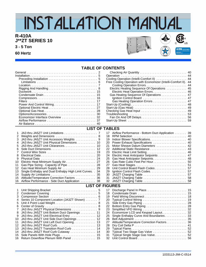
R-410A J**ZT SERIES 10 3 - 5 Ton 60 Hertz 1033113-JIM-C-0514 TABLE OF CONTENTS General . . . . . . . . . . . . . . . . . . . . . . . . . . . . . . . . . . . . . . . . . . 2 Installation . . . . . . . . . . . . . . . . . . . . . . . . . . . . . . . . . . . . . . . . 5 Preceding Installation . . . . . . . . . . . . . . . . . . . . . . . . . . . . . 5 Limitations . . . . . . . . . . . . . . . . . . . . . . . . . . . . . . . . . . . . 6 Location. . . . . . . . . . . . . . . . . . . . . . . . . . . . . . . . . . . . . . . . 7 Rigging And Handling . . . . . . . . . . . . . . . . . . . . . . . . . . . . . 8 Ductwork . . . . . . . . . . . . . . . . . . . . . . . . . . . . . . . . . . . . . . 15 Condensate Drain . . . . . . . . . . . . . . . . . . . . . . . . . . . . . . . 15 Compressors . . . . . . . . . . . . . . . . . . . . . . . . . . . . . . . . . . . 16 Filters . . . . . . . . . . . . . . . . . . . . . . . . . . . . . . . . . . . . . . . . 17 Power And Control Wiring . . . . . . . . . . . . . . . . . . . . . . . . . 17 Optional Electric Heat . . . . . . . . . . . . . . . . . . . . . . . . . . . . 27 Optional Gas Heat. . . . . . . . . . . . . . . . . . . . . . . . . . . . . . . 28 Options/Accessories . . . . . . . . . . . . . . . . . . . . . . . . . . . . . 30 Economizer Interface Overview . . . . . . . . . . . . . . . . . . . . 32 Airflow Performance . . . . . . . . . . . . . . . . . . . . . . . . . . . . . 37 Air Balance . . . . . . . . . . . . . . . . . . . . . . . . . . . . . . . . . . . . 40 Checking Air Quantity . . . . . . . . . . . . . . . . . . . . . . . . . . . . 40 Operation . . . . . . . . . . . . . . . . . . . . . . . . . . . . . . . . . . . . . . . 44 Cooling Operation (Intelli-Comfort II) . . . . . . . . . . . . . . . . . . 44 Free Cooling Operation with Economizer (Intelli-Comfort II) . 44 Cooling Operation Errors . . . . . . . . . . . . . . . . . . . . . . . . 44 Electric Heating Sequence Of Operations . . . . . . . . . . . . 45 Electric Heat Operation Errors . . . . . . . . . . . . . . . . . . . . 46 Gas Heating Sequence Of Operations . . . . . . . . . . . . . . . 47 Ignition Control Board . . . . . . . . . . . . . . . . . . . . . . . . . . 47 Gas Heating Operation Errors . . . . . . . . . . . . . . . . . . . . 47 Start-Up (Cooling) . . . . . . . . . . . . . . . . . . . . . . . . . . . . . . . . . 48 Start-Up (Gas Heat) . . . . . . . . . . . . . . . . . . . . . . . . . . . . . . . 49 Checking Gas Heat Input . . . . . . . . . . . . . . . . . . . . . . . . . . . 49 Troubleshooting . . . . . . . . . . . . . . . . . . . . . . . . . . . . . . . . . . 53 Fan On And Off Delays . . . . . . . . . . . . . . . . . . . . . . . . . . . 56 Start-Up Sheet . . . . . . . . . . . . . . . . . . . . . . . . . . . . . . . . . . . 59 LIST OF TABLES 1 JA3 thru JA5ZT Unit Limitations . . . . . . . . . . . . . . . . . . . . 7 2 Weights and Dimensions . . . . . . . . . . . . . . . . . . . . . . . . . 8 3 JA3 thru JA5ZT Unit Accessory Weights . . . . . . . . . . . . . 9 4 JA3 thru JA5ZT Unit Physical Dimensions . . . . . . . . . . . 10 5 JA3 thru JA5ZT Unit Clearances . . . . . . . . . . . . . . . . . . . 10 6 Side Duct Dimensions . . . . . . . . . . . . . . . . . . . . . . . . . . . 12 7 Control Wire Sizes . . . . . . . . . . . . . . . . . . . . . . . . . . . . . 19 8 Electrical Data . . . . . . . . . . . . . . . . . . . . . . . . . . . . . . . . . 20 9 Physical Data . . . . . . . . . . . . . . . . . . . . . . . . . . . . . . . . . 24 10 Electric Heat Minimum Supply Air . . . . . . . . . . . . . . . . . . 27 11 Gas Pipe Sizing - Capacity of Pipe . . . . . . . . . . . . . . . . . 28 12 Gas Heat Minimum Supply Air . . . . . . . . . . . . . . . . . . . . 29 13 Single Enthalpy and Dual Enthalpy High Limit Curves. . 34 14 Supply Air Limitations . . . . . . . . . . . . . . . . . . . . . . . . . . . 35 15 Altitude/Temperature Correction Factors . . . . . . . . . . . . 36 16 Airflow Performance - Side Duct Application . . . . . . . . . 38 17 Airflow Performance - Bottom Duct Application . . . . . . . 39 18 RPM Selection . . . . . . . . . . . . . . . . . . . . . . . . . . . . . . . . 40 19 Indoor Blower Specifications . . . . . . . . . . . . . . . . . . . . . . 40 20 Power Exhaust Specifications . . . . . . . . . . . . . . . . . . . . 40 21 Motor Sheave Datum Diameters . . . . . . . . . . . . . . . . . . 42 22 Additional Static Resistance . . . . . . . . . . . . . . . . . . . . . . 43 23 Electric Heat Limit Setting . . . . . . . . . . . . . . . . . . . . . . . . 46 24 Electric Heat Anticipator Setpoints . . . . . . . . . . . . . . . . . 47 25 Gas Heat Anticipator Setpoints . . . . . . . . . . . . . . . . . . . . 48 26 Gas Rate Cubic Feet Per Hour . . . . . . . . . . . . . . . . . . . . 50 27 Gas Heat Stages . . . . . . . . . . . . . . . . . . . . . . . . . . . . . . . 51 28 Unit Control Board Flash Codes . . . . . . . . . . . . . . . . . . . 57 29 Ignition Control Flash Codes . . . . . . . . . . . . . . . . . . . . . . 57 30 JA3ZT Charging Table . . . . . . . . . . . . . . . . . . . . . . . . . . 57 31 JA4ZT Charging Table . . . . . . . . . . . . . . . . . . . . . . . . . . 58 32 JA5ZT Charging Table . . . . . . . . . . . . . . . . . . . . . . . . . . 58 LIST OF FIGURES 1 Unit Shipping Bracket . . . . . . . . . . . . . . . . . . . . . . . . . . . 5 2 Condenser Covering . . . . . . . . . . . . . . . . . . . . . . . . . . . . 5 3 Compressor Section . . . . . . . . . . . . . . . . . . . . . . . . . . . . 6 4 Series 10 Component Location (JA3ZT Shown) . . . . . . . 7 5 Unit 4 Point Load Weight . . . . . . . . . . . . . . . . . . . . . . . . . 8 6 Center of Gravity . . . . . . . . . . . . . . . . . . . . . . . . . . . . . . . 8 7 JA3 thru JA5ZT Physical Dimensions . . . . . . . . . . . . . . . 9 8 JA3 thru JA5ZT Unit Bottom Duct Openings . . . . . . . . . 11 9 JA3 thru JA5ZT Unit Electrical Entry . . . . . . . . . . . . . . . 12 10 JA3 thru JA5ZT Unit Side Duct Openings . . . . . . . . . . . 12 11 JA3 thru JA5ZT Unit Left Duct Opening . . . . . . . . . . . . . 13 12 JA3 thru JA5ZT Roof Curb . . . . . . . . . . . . . . . . . . . . . . . 13 13 JA3 thru JA5ZT Transition Roof Curb . . . . . . . . . . . . . . 14 14 JA3 thru JA5ZT Roof Curb Cutaway . . . . . . . . . . . . . . . 14 15 Side Panels With Hole Plugs . . . . . . . . . . . . . . . . . . . . . 15 16 Return Downflow Plenum With Panel . . . . . . . . . . . . . . 15 17 Discharge Panel In Place . . . . . . . . . . . . . . . . . . . . . . . . 15 18 Condensate Drain . . . . . . . . . . . . . . . . . . . . . . . . . . . . . 15 19 Field Wiring Disconnect . . . . . . . . . . . . . . . . . . . . . . . . . 18 20 Typical Control Wiring . . . . . . . . . . . . . . . . . . . . . . . . . . 19 21 Side Entry Gas Piping . . . . . . . . . . . . . . . . . . . . . . . . . . 28 22 Bottom Entry Gas Piping . . . . . . . . . . . . . . . . . . . . . . . . 28 23 Simplified VFD Wiring . . . . . . . . . . . . . . . . . . . . . . . . . . 32 24 Economizer LCD and Keypad Layout. . . . . . . . . . . . . . . 32 25 Single Enthalpy Curve And Boundaries . . . . . . . . . . . . . 33 26 Belt Adjustment . . . . . . . . . . . . . . . . . . . . . . . . . . . . . . . 35 27 Altitude/Temperature Correction Factors . . . . . . . . . . . . 36 28 Dry Coil Delta P . . . . . . . . . . . . . . . . . . . . . . . . . . . . . . . 41 29 Typical Flame . . . . . . . . . . . . . . . . . . . . . . . . . . . . . . . . . 52 30 Typical Two Stage Gas Valve . . . . . . . . . . . . . . . . . . . . 52 31 Typical Single Stage Gas Valve . . . . . . . . . . . . . . . . . . . 52 32 Unit Control Board . . . . . . . . . . . . . . . . . . . . . . . . . . . . . 56
-
Upload
khangminh22 -
Category
Documents
-
view
1 -
download
0
Transcript of R-410A J**ZT SERIES 10 - Johnson Controls
R-410AJ**ZT SERIES 10
3 - 5 Ton
60 Hertz
1033113-JIM-C-0514
TABLE OF CONTENTSGeneral . . . . . . . . . . . . . . . . . . . . . . . . . . . . . . . . . . . . . . . . . . 2Installation . . . . . . . . . . . . . . . . . . . . . . . . . . . . . . . . . . . . . . . . 5
Preceding Installation . . . . . . . . . . . . . . . . . . . . . . . . . . . . . 5Limitations . . . . . . . . . . . . . . . . . . . . . . . . . . . . . . . . . . . . 6
Location. . . . . . . . . . . . . . . . . . . . . . . . . . . . . . . . . . . . . . . . 7Rigging And Handling . . . . . . . . . . . . . . . . . . . . . . . . . . . . . 8Ductwork . . . . . . . . . . . . . . . . . . . . . . . . . . . . . . . . . . . . . . 15Condensate Drain . . . . . . . . . . . . . . . . . . . . . . . . . . . . . . . 15Compressors. . . . . . . . . . . . . . . . . . . . . . . . . . . . . . . . . . . 16Filters . . . . . . . . . . . . . . . . . . . . . . . . . . . . . . . . . . . . . . . . 17Power And Control Wiring. . . . . . . . . . . . . . . . . . . . . . . . . 17Optional Electric Heat . . . . . . . . . . . . . . . . . . . . . . . . . . . . 27Optional Gas Heat. . . . . . . . . . . . . . . . . . . . . . . . . . . . . . . 28Options/Accessories . . . . . . . . . . . . . . . . . . . . . . . . . . . . . 30Economizer Interface Overview . . . . . . . . . . . . . . . . . . . . 32Airflow Performance . . . . . . . . . . . . . . . . . . . . . . . . . . . . . 37Air Balance . . . . . . . . . . . . . . . . . . . . . . . . . . . . . . . . . . . . 40
Checking Air Quantity . . . . . . . . . . . . . . . . . . . . . . . . . . . . 40Operation . . . . . . . . . . . . . . . . . . . . . . . . . . . . . . . . . . . . . . . 44Cooling Operation (Intelli-Comfort II) . . . . . . . . . . . . . . . . . . 44Free Cooling Operation with Economizer (Intelli-Comfort II) . 44
Cooling Operation Errors . . . . . . . . . . . . . . . . . . . . . . . . 44Electric Heating Sequence Of Operations . . . . . . . . . . . . 45
Electric Heat Operation Errors . . . . . . . . . . . . . . . . . . . . 46Gas Heating Sequence Of Operations . . . . . . . . . . . . . . . 47
Ignition Control Board . . . . . . . . . . . . . . . . . . . . . . . . . . 47Gas Heating Operation Errors . . . . . . . . . . . . . . . . . . . . 47
Start-Up (Cooling) . . . . . . . . . . . . . . . . . . . . . . . . . . . . . . . . . 48Start-Up (Gas Heat) . . . . . . . . . . . . . . . . . . . . . . . . . . . . . . . 49Checking Gas Heat Input . . . . . . . . . . . . . . . . . . . . . . . . . . . 49Troubleshooting . . . . . . . . . . . . . . . . . . . . . . . . . . . . . . . . . . 53
Fan On And Off Delays. . . . . . . . . . . . . . . . . . . . . . . . . . . 56Start-Up Sheet . . . . . . . . . . . . . . . . . . . . . . . . . . . . . . . . . . . 59
LIST OF TABLES1 JA3 thru JA5ZT Unit Limitations . . . . . . . . . . . . . . . . . . . . 72 Weights and Dimensions . . . . . . . . . . . . . . . . . . . . . . . . . 83 JA3 thru JA5ZT Unit Accessory Weights . . . . . . . . . . . . . 94 JA3 thru JA5ZT Unit Physical Dimensions . . . . . . . . . . . 105 JA3 thru JA5ZT Unit Clearances . . . . . . . . . . . . . . . . . . . 106 Side Duct Dimensions . . . . . . . . . . . . . . . . . . . . . . . . . . . 127 Control Wire Sizes . . . . . . . . . . . . . . . . . . . . . . . . . . . . . 198 Electrical Data . . . . . . . . . . . . . . . . . . . . . . . . . . . . . . . . . 209 Physical Data . . . . . . . . . . . . . . . . . . . . . . . . . . . . . . . . . 24
10 Electric Heat Minimum Supply Air . . . . . . . . . . . . . . . . . . 2711 Gas Pipe Sizing - Capacity of Pipe . . . . . . . . . . . . . . . . . 2812 Gas Heat Minimum Supply Air . . . . . . . . . . . . . . . . . . . . 2913 Single Enthalpy and Dual Enthalpy High Limit Curves. . 3414 Supply Air Limitations . . . . . . . . . . . . . . . . . . . . . . . . . . . 3515 Altitude/Temperature Correction Factors . . . . . . . . . . . . 3616 Airflow Performance - Side Duct Application . . . . . . . . . 38
17 Airflow Performance - Bottom Duct Application . . . . . . . 3918 RPM Selection . . . . . . . . . . . . . . . . . . . . . . . . . . . . . . . . 4019 Indoor Blower Specifications . . . . . . . . . . . . . . . . . . . . . . 4020 Power Exhaust Specifications . . . . . . . . . . . . . . . . . . . . 4021 Motor Sheave Datum Diameters . . . . . . . . . . . . . . . . . . 4222 Additional Static Resistance . . . . . . . . . . . . . . . . . . . . . . 4323 Electric Heat Limit Setting . . . . . . . . . . . . . . . . . . . . . . . . 4624 Electric Heat Anticipator Setpoints . . . . . . . . . . . . . . . . . 4725 Gas Heat Anticipator Setpoints . . . . . . . . . . . . . . . . . . . . 4826 Gas Rate Cubic Feet Per Hour . . . . . . . . . . . . . . . . . . . . 5027 Gas Heat Stages . . . . . . . . . . . . . . . . . . . . . . . . . . . . . . . 5128 Unit Control Board Flash Codes . . . . . . . . . . . . . . . . . . . 5729 Ignition Control Flash Codes . . . . . . . . . . . . . . . . . . . . . . 5730 JA3ZT Charging Table . . . . . . . . . . . . . . . . . . . . . . . . . . 5731 JA4ZT Charging Table . . . . . . . . . . . . . . . . . . . . . . . . . . 5832 JA5ZT Charging Table . . . . . . . . . . . . . . . . . . . . . . . . . . 58
LIST OF FIGURES1 Unit Shipping Bracket . . . . . . . . . . . . . . . . . . . . . . . . . . . 52 Condenser Covering . . . . . . . . . . . . . . . . . . . . . . . . . . . . 53 Compressor Section . . . . . . . . . . . . . . . . . . . . . . . . . . . . 64 Series 10 Component Location (JA3ZT Shown) . . . . . . . 75 Unit 4 Point Load Weight . . . . . . . . . . . . . . . . . . . . . . . . . 86 Center of Gravity . . . . . . . . . . . . . . . . . . . . . . . . . . . . . . . 87 JA3 thru JA5ZT Physical Dimensions . . . . . . . . . . . . . . . 98 JA3 thru JA5ZT Unit Bottom Duct Openings . . . . . . . . . 119 JA3 thru JA5ZT Unit Electrical Entry . . . . . . . . . . . . . . . 12
10 JA3 thru JA5ZT Unit Side Duct Openings . . . . . . . . . . . 1211 JA3 thru JA5ZT Unit Left Duct Opening . . . . . . . . . . . . . 1312 JA3 thru JA5ZT Roof Curb . . . . . . . . . . . . . . . . . . . . . . . 1313 JA3 thru JA5ZT Transition Roof Curb . . . . . . . . . . . . . . 1414 JA3 thru JA5ZT Roof Curb Cutaway . . . . . . . . . . . . . . . 1415 Side Panels With Hole Plugs . . . . . . . . . . . . . . . . . . . . . 1516 Return Downflow Plenum With Panel . . . . . . . . . . . . . . 15
17 Discharge Panel In Place . . . . . . . . . . . . . . . . . . . . . . . . 1518 Condensate Drain . . . . . . . . . . . . . . . . . . . . . . . . . . . . . 1519 Field Wiring Disconnect . . . . . . . . . . . . . . . . . . . . . . . . . 1820 Typical Control Wiring . . . . . . . . . . . . . . . . . . . . . . . . . . 1921 Side Entry Gas Piping . . . . . . . . . . . . . . . . . . . . . . . . . . 2822 Bottom Entry Gas Piping . . . . . . . . . . . . . . . . . . . . . . . . 2823 Simplified VFD Wiring . . . . . . . . . . . . . . . . . . . . . . . . . . 3224 Economizer LCD and Keypad Layout. . . . . . . . . . . . . . . 3225 Single Enthalpy Curve And Boundaries . . . . . . . . . . . . . 3326 Belt Adjustment . . . . . . . . . . . . . . . . . . . . . . . . . . . . . . . 3527 Altitude/Temperature Correction Factors . . . . . . . . . . . . 3628 Dry Coil Delta P . . . . . . . . . . . . . . . . . . . . . . . . . . . . . . . 4129 Typical Flame . . . . . . . . . . . . . . . . . . . . . . . . . . . . . . . . . 5230 Typical Two Stage Gas Valve . . . . . . . . . . . . . . . . . . . . 5231 Typical Single Stage Gas Valve . . . . . . . . . . . . . . . . . . . 5232 Unit Control Board . . . . . . . . . . . . . . . . . . . . . . . . . . . . . 56

1033113-JIM-C-0514
2 Johnson Controls Unitary Products
General
Johnson Controls Series 10 units are single package air conditioners with optional gas heating designed for outdoor installation on a rooftop or slab and for non-residential use. These units can be equipped with factory or field installed electric heaters for heating applications.
These units are completely assembled on rigid, permanently attached base rails. All piping, refrigerant charge, and electrical wiring is factory installed and tested. The units require electric power, gas supply (where applicable), and duct connections. The electric heaters have nickel-chrome elements and utilize single-point power connection.
Safety Considerations
This is a safety alert symbol. When you see this symbol on labels or in manuals, be alert to the potential for personal injury.
Understand and pay particular attention the signal words DANGER, WARNING or CAUTION.
DANGER indicates an imminently hazardous situation, which, if not avoided, will result in death or serious injury.
WARNING indicates a potentially hazardous situation, which, if not avoided, could result in death or serious injury.
CAUTION indicates a potentially hazardous situation, which, if not avoided may result in minor or moderate injury. It is also used to alert against unsafe practices and hazards involving only property damage.
Due to system pressure, moving parts, and electrical components, installation and servicing of air conditioning equipment can be hazardous. Only qualified, trained service personnel should install, repair, or service this equipment. Untrained personnel can perform basic maintenance functions of cleaning coils and filters and replacing filters.
Observe all precautions in the literature, labels, and tags accompanying the equipment whenever working on air conditioning equipment. Be sure to follow all other applicable safety precautions and codes including ANSI Z223.1 or CSA-B149.1- latest edition.
Wear safety glasses and work gloves. Use quenching cloth and have a fire extinguisher available during brazing operations.
Improper installation may create a condition where the operation of the product could cause personal injury or property damage. Improper installation, adjustment, alteration, service or maintenance can cause injury or property damage. Refer to this manual for assistance or for additional information, consult a qualified contractor, installer or service agency.
This product must be installed in strict compliance with the installation instructions and any applicable local, state and national codes including, but not limited to building, electrical, and mechanical codes.
Before performing service or maintenance operations on unit, turn off main power switch to unit. Electrical shock could cause personal injury. Improper installation, adjustment, alteration, service or maintenance can cause injury or property damage. Refer to this manual. For assistance or additional information consult a qualified installer, service agency or the gas supplier.
This system uses R-410A Refrigerant which operates at higher pressures than R-22. No other refrigerant may be used in this system. Gage sets, hoses, refrigerant containers and recovery systems must be designed to handle R-410A. If you are unsure, consult the equipment manufacturer. Failure to use R-410A compatible servicing equipment may result in property damage or injury.
If the information in this manual is not followed exactly, a fire or explosion may result causing property damage, personal injury or loss of life.
Do not store or use gasoline or other flammable vapors and liquids in the vicinity of this or any other appliance.
WHAT TO DO IF YOU SMELL GAS:
a. Do not try to light any appliance.
b. Do not touch any electrical switch; do not use any phone in your building.
c. Immediately call your gas supplier from a neighbor’s phone. Follow the gas supplier’s instructions.
d. If you cannot reach your gas supplier, call the fire department.
Installation and service must be performed by a qualified installer, service agency or the gas supplier.

1033113-JIM-C-0514
Johnson Controls Unitary Products 3
Inspection
As soon as a unit is received, it should be inspected for possible damage during transit. If damage is evident, the extent of the damage should be noted on the carrier’s freight bill. A separate request for inspection by the carrier’s agent should be made in writing.
Reference
Additional information is available in the following reference forms:
• Technical Guide - JA3 thru JA5ZT, 1041167
• General Installation - JA3 thru JA5ZT, 1033113
• Pre-start & Post-start Check List
• Economizer Accessory -Downflow Factory InstalledDownflow Field InstalledHorizontal Field Installed
• Motorized Outdoor Air Damper
• Manual Outdoor Air Damper (0-100%)
• Manual Outdoor Air Damper (0-35%)
• Gas Heat Propane Conversion Kit
• Gas Heat High Altitude Kit (Natural Gas)
• Gas Heat High Altitude Kit (Propane)
• –60F Gas Heat Kit
• Electric Heater Accessory
Renewal Parts
Contact your local Johnson Controls parts distribution center for authorized replacement parts.
Approvals
Design certified by CSA as follows:
1. For use as a cooling only unit, cooling unit with supplemental electric heat or a forced air furnace.
2. For outdoor installation only.
3. For installation on combustible material and may be installed directly on combustible flooring or, in the U.S., on wood flooring or Class A, Class B or Class C roof covering materials.
4. For use with natural gas (convertible to LP with kit).
This product must be installed in strict compliance with the enclosed installation instructions and any applicable local, state and national codes including, but not limited to, building, electrical, and mechanical codes.
The furnace and its individual shut-off valve must be disconnected from the gas supply piping system during any pressure testing at pressures in excess of 1/2 PSIG.
Pressures greater than 1/2 PSIG will cause gas valve damage resulting in a hazardous condition. If it is subjected to a pressure greater than 1/2 PSIG, the gas valve must be replaced.
The furnace must be isolated from the gas supply piping system by closing its individual manual shut-off valve during any pressure testing of the gas supply piping system at test pressures equal to or less than 1/2 PSIG
This product must be installed in strict compliance with the enclosed installation instructions and any applicable local, state, and national codes including, but not limited to, building, electrical, and mechanical codes.
Improper installation may create a condition where the operation of the product could cause personal injury or property damage.
This system uses R-410A Refrigerant which operates at higher pressures than R-22. No other refrigerant may be used in this system.

1033113-JIM-C-0514
4 Johnson Controls Unitary Products
Nomenclature
Z TJA5 N08 A 2 A ZZ 1 0 1 2 4 A
Product Category
T = 18 SEER Ultra High Eff. A/C
Product Generation
1 = First Generation
C00 = Cooling Only. No heat installed
Heat Type and Nominal Heat Capacity(Unit Size Allowed)
A05 = 49 MBH Output Aluminized Steel, Single Stage (JA3, JA4)A07 = 65 MBH Output Aluminized Steel, Single Stage (JA3, JA4, JA5)A09 = 97 MBH Output Aluminized Steel, Single Stage (JA3, JA4, JA5)A13 = 129 MBH Output Aluminized Steel, Single Stage (JA5)B05 = 49 MBH Output Stainless Sleel, Single Stage (JA3, JA4)B07 = 65 MBH Output Stainless Steel, Single Stage (JA3, JA4, JA5)B09 = 97 MBH Output Stainless Steel, Single Stage (JA3, JA4, JA5)B13 = 129 MBH Output Stainless Steel, Single Stage (JA5)
E03 = 3 KW (JA3)E06 = 6 KW (JA3, JA4, JA5)E08 = 9 KW (JA3, JA4, JA5)E15 = 15 KW (JA3, JA4, JA5)E20 = 20 KW (JA4, JA5)E23 = 24 KW (JA5)
Single Stage Natural Gas Heat Options
Electric Heat Options
Nominal Cooling Capacity
JA3 = 3 TonJA4 = 4 TonJA5 = 5 Ton
Product Identifier
Z = A/C, Single Pkg. R410A
Voltage
2 = 208/230-3-604 = 460-3-605 = 575-3-60
Product Style
A = Style AB = Style BC = Style C
A = No Options Installed
Installation Options
B = Option 1C = Option 2D = Options 1 & 2E = Option 3F = Option 4G = Options 1 & 3H = Options 1 & 4J = Options 1, 2 & 3K = Options 1, 2, & 4L = Options 1,3 & 4M = Options 1, 2, 3, & 4N = Options 2 & 3P = Options 2 & 4Q = Options 2, 3, & 4R = Options 3 & 4S = Option 5T = Options 1 & 5U = Options 1, 3, & 5V = Options 1, 4, & 5W = Options 1, 3, 4, & 5X = Options 3 & 5Y = Options 4 & 5Z = Options 3, 4 & 5
1 = Disconnect2 = Non-Pwr'd Conv. Outlet3 = Smoke Detector S.A.4 = Smoke Detector R.A.5 = Pwr'd Conv. Outlet
Options
3-5 Ton JCI Series 10 Model Number Nomenclature
Two Stage Natural Gas Heat Options
N05 = 49 MBH Output Aluminized Steel, Two Stage (JA3, JA4)N07 = 65 MBH Output Aluminized Steel, Two Stage (JA3, JA4, JA5)N09 = 97 MBH Output Aluminized Steel, Two Stage (JA3, JA4, JA5)N13 = 129 MBH Output Aluminized Steel, Two Stage (JA5)S05 = 49 MBH Output Stainless Sleel, Two Stage (JA3, JA4)S07 = 65 MBH Output Stainless Steel, Two Stage (JA3, JA4, JA5)S09 = 97 MBH Output Stainless Steel, Two Stage (JA3, JA4, JA5)S13 = 129 MBH Output Stainless Steel, Two Stage (JA5)
Johnson Controller Metasys FEC-2611 (BACnet MS/TP protocol), SAS, RAS, OAS, DFS, APS
SS Drain Pan
Configuration Options (not required for all units)
CPC Controller, DFS, APSJohnson Controller UNT 1126 (N2 protocol), DFS, APS
Honeywell Controller, DFS, APSNovar Controller, DFS, APS
Simplicity IntelliComfort II Controller
Simplicity IntelliComfort II Controller w/Simplicity®Linc
2" Pleated Filters, MERV 7
BAS Ready Unit with Economizer
Any Combination of Additional Options that Don’t Have an Option Code Pre-assigned
Phase MonitorCoil GuardDirty Filter Switch
Additional Options
American FlagTechnicoat Condenser CoilTechnicoat Evaporator Coil
ZZ = If desired option combination is not listed above, ZZ will be assigned and configuration options will belocated in digits 15-18.
Commercial Comfort System (CCS) Rtu Controller
4" Pleated Filters, MERV 13
ElectroFin Condenser CoilElectroFin Evaporator Coil
Shipping Bag
A = Std. MotorD = Std. Motor/Motorized Damper (Downflow Only)H = Std Motor/Low Leak Econ/Barometric Relief (Downflow, Slab Economizer Only)J = Std Motor/Low Leak Econ/Power Exhaust (Downflow, Slab Economizer Only)E = Std Motor/Horizontal Economizer (No Baro)N = Hi StaticR = Hi Static/Motorized Damper (Downflow Only)V = Hi Static Mtr/Low Leak Econ/Barometric Relief (Downflow, Slab Economizer Only)W = Hi Static Mtr/Low Leak Econ/Power Exhaust (Downflow, Slab Economizer Only)S = Hi Static Mtr/Horizontal Economizer (No Baro)
Airflow

1033113-JIM-C-0514
Johnson Controls Unitary Products 5
Installation
Installation Safety Information
Read these instructions before continuing this appliance installation. This is an outdoor combination heating and cooling unit. The installer must assure that these instructions are made available to the consumer and with instructions to retain them for future reference.
1. Refer to the unit rating plate for the approved type of gas for this product.
2. Install this unit only in a location and position as specified on Page 7 of these instructions.
3. Never test for gas leaks with an open flame. Use commercially available soap solution made specifically for the detection of leaks when checking all connections, as specified on Pages 5, 29, 30 and 49 of these instructions.
4. Always install furnace to operate within the furnace's intended temperature-rise range with the duct system and within the allowable external static pressure range, as specified on the unit name/rating plate, specified on Page 52 of these instructions.
5. This equipment is not to be used for temporary heating of buildings or structures under construction.
It is permitted to use the unit for heating and cooling of buildings or structures under construction where the application and use must comply with all manufacturer's installation instructions including:
• Proper installation of vent outlet air and combustion air intake hoods;
• Unit must be operated under thermostatic control;
• Return and supply air ducts must be sealed to the unit;
• Air filters in place;
• Unit furnace input rate and temperature rise must be set per rating plate marking;
• Return air temperature maintained between 55ºF (13ºC) and 80ºF (27ºC);
• Upon completion of the construction phase and prior to formal start up and commissioning, the unit, duct work and components should be thoroughly cleaned and inspected to assure that operation of the unit during construction has not contaminated the unit.
NOTE: Should the unit be used during the construction phase the standard limited warranty provisions go into effect once the unit is placed into operation.
Preceding Installation
1. Remove the two screws holding the brackets in the front, rear and compressor side fork-lift slots.
Figure 1: Unit Shipping Bracket
2. Turn each bracket toward the ground and the protective plywood covering will drop to the ground.
3. Remove the condenser coil external protective covering prior to operation.
4. Remove the toolless doorknobs and instruction packet prior to installation.
Figure 2: Condenser Covering
FIRE OR EXPLOSION HAZARD
Failure to follow the safety warning exactly could result in serious injury, death or property damage.
Never test for gas leaks with an open flame. use a commercially available soap solution made specifically for the detection of leaks to check all connections. A fire or explosion may result causing property damage, personal injury or loss of life.
BracketScrews Turn down
Condenser Coil External Protective Covering
Barometric Relief Hood in Shipping Location(if Included)

1033113-JIM-C-0514
6 Johnson Controls Unitary Products
Figure 3: Compressor Section
5. If a factory option convenience outlet is installed, the weatherproof outlet cover must be field installed. The cover shall be located behind the filter access panel. To install the cover, remove the shipping label covering the convenience outlet, follow the instructions on the back of the weatherproof cover box, and attach the cover to the unit using the (4) screws provided.
Limitations
These units must be installed in accordance with the following:
In U.S.A.:
1. National Electrical Code, ANSI/NFPA No. 70 - Latest Edition
2. National Fuel Gas Code, ANSI Z223.1 - Latest Edition
3. Gas-Fired Central Furnace Standard, ANSI Z21.47a. - Latest Edition
4. Local building codes, and
5. Local gas utility requirements
In Canada:
1. Canadian Electrical Code, CSA C22.1
2. Installation Codes, CSA - B149.1.
3. Local plumbing and waste water codes, and
4. Other applicable local codes.
Refer to unit application data found in this document.
After installation, gas fired units must be adjusted to obtain a temperature rise within the range specified on the unit rating plate.
If components are to be added to a unit to meet local codes, they are to be installed at the dealer’s and/or customer’s expense.
Size of unit for proposed installation should be based on heat loss/heat gain calculation made according to the methods of Air Conditioning Contractors of America (ACCA).
This furnace is not to be used for temporary heating of buildings or structures under construction.
208/230-3-60 units with factory installed Powered Convenience Outlet Option are wired for 230v power supply. Change tap on transformer for 208-3-60 operation. See unit wiring diagram.
Toolless Doorknobs
Installation Instruction Packet
The Simplicity® control board used in this product will effectively operate the cooling system down to 0°F when this product is applied in a comfort cooling application for people. An economizer is typically included in this type of application. When applying this product for process cooling applications (computer rooms, switchgear, etc.), please reference applications bulletin AE-011-07 or call the applications department for Unitary Products @ 1-877-UPG-SERV for guidance. Additional accessories may be needed for stable operation at temperatures below 30° F.

1033113-JIM-C-0514
Johnson Controls Unitary Products 7
Figure 4: Series 10 Component Location (JA3ZT Shown)
Location
Use the following guidelines to select a suitable location for these units:
1. Unit is designed for outdoor installation only.
2. Condenser coils must have an unlimited supply of air. Where a choice of location is possible, position the unit on either north or east side of building.
3. Suitable for mounting on roof curb.
4. For ground level installation, use a level concrete slab with a minimum thickness of 4 inches. The length and width should be at least 6 inches greater than the unit base rails. Do not tie slab to the building foundation.
5. Roof structures must be able to support the weight of the unit and its options/accessories. Unit must be installed on a solid, level roof curb or appropriate angle iron frame.
6. Maintain level tolerance to 1/2” across the entire width and length of unit.
Intelligent control board for safe and efficient
operation
w/screw connectors for T-stat wiring and Network
ConnectionsDisconnect location
(optional disconnect switch)
Filter access (2" or 4”
filter options)
Filter drier (solid core)
Slide out motor and blower assembly for
easy adjustment and service
Base rails w/forklift slots
(three sides) and lifting
holes
Toolless door latch
Side entry power and control wiring
knockouts
Premium EfficiencyBelt-drive blower motor
Power ventor motor
20-gauge aluminized steel tubular heat
exchanger for long life (stainless steel option)
One or Two stage gas heating to maintain warm, comfortable
temperatureSlide-out drain pan with ¾" NPT connection
Compressor access (High-Efficiency 2-Stage compressor)
Second model nameplate inside hinged access
panel
Roof curbs in eight-andfourteen-inch heights.
Roof curbs for transitioningfrom Series 5 footprint
to the ZT Series 10 footprintare available
(field-installed accessory)
Micro-Channel AluminumTube/Aluminum Fin
Condenser
High EfficiencySineWave Fin Evaporator Coil“Simplicity®” Intelli-Comfort II™
w/IntelliSpeed™ Supply Fan Controls
ECM Outdoor Fan motor
VFD
Table 1: JA3 thru JA5ZT Unit Limitations
Size(Tons)
Model Unit Voltage
Unit Limitations
Applied Voltage Outdoor DB Temp
Min Max Max (°F)
JA3(3.0)
J**ZT
208/230-3-60 187 252 125
460-3-60 432 504 125
575-3-60 540 630 125
JA4(4.0)
J**ZT
208/230-3-60 187 252 125
460-3-60 432 504 125
575-3-60 540 630 125
JA5(5.0)
J**ZT
208/230-3-60 187 252 125
460-3-60 432 504 125
575-3-60 540 630 125

1033113-JIM-C-0514
8 Johnson Controls Unitary Products
Clearances
All units require particular clearances for proper operation and service. Installer must make provisions for adequate combustion and ventilation air in accordance with section 5.3 of Air for Combustion and Ventilation of the National Fuel Gas Code, ANSI Z223.1 – Latest Edition (in U.S.A.), or Sections 7.2, 7.3, or 7.4 of Gas Installation Codes, CSA-B149.1 (in Canada) - Latest Edition, and/or applicable provisions of the local building codes. Refer to Table 5 for clearances required for combustible construction, servicing, and proper unit operation.
Rigging And Handling
Exercise care when moving the unit. Do not remove any packaging until the unit is near the place of installation. Rig the unit by attaching chain or cable slings to the lifting holes provided in the base rails. Spreader bars, whose length exceeds the largest dimension across the unit, MUST be used across the top of the unit.
Units may be moved or lifted with a forklift. Slotted openings in the base rails are provided for this purpose.
LENGTH OF FORKS MUST BE A MINIMUM OF 60 INCHES.
Figure 5: Unit 4 Point Load Weight
Figure 6: Center of Gravity
Excessive exposure of this furnace to contaminated combustion air may result in equipment damage or personal injury. Typical contaminates include: permanent wave solution, chlorinated waxes and cleaners, chlorine based swimming pool chemicals, water softening chemicals, carbon tetrachloride, Halogen type refrigerants, cleaning solvents (e.g. perchloroethylene), printing inks, paint removers, varnishes, hydrochloric acid, cements and glues, antistatic fabric softeners for clothes dryers, masonry acid washing materials.
Do not permit overhanging structures or shrubs to obstruct condenser air discharge outlet, combustion air inlet or vent outlets.
If a unit is to be installed on a roof curb other than a Johnson Controls roof curb, gasketing must be applied to all surfaces that come in contact with the unit underside.
Before lifting, make sure the unit weight is distributed equally on the rigging cables so it will lift evenly.
All panels must be secured in place when the unit is lifted.
The condenser coils should be protected from rigging cable damage with plywood or other suitable material.
D
A
CBLEFTFRONT
XY
LEFTFRONT
Table 2: Weights and Dimensions
Size(Tons)
ModelWeight (lbs.) Center of Gravity 4 Point Load Location (lbs.)
Shipping Operating X Y A B C DJA3(3)
J**ZT 927 922 42.4 24.7 202 184 255 281
JA4(4)
J**ZT 965 960 42.5 25.5 217 198 260 285
JA55)
J**ZT 973 968 41.6 25.5 223 196 257 293

1033113-JIM-C-0514
Johnson Controls Unitary Products 9
Figure 7: JA3 thru JA5ZT Physical Dimensions
Table 3: JA3 thru JA5ZT Unit Accessory Weights
Unit AccessoryWeight (lbs.)
Shipping OperatingEconomizer 90 85
Power Exhaust 40 35Electric Heat1 49 49
Gas Heat2 110 110
1. Weight given is for the maximum heater size available (24KW).2. Weight given is for the maximum number of tube heat exchangers
available (8 tube).
LEFT
A
59.00
CD
E
F
4.19
27.31
89.00
21.19
11.38
15.38
59.00
15.38
29.69
15.25
FRONT
SEE DETAIL BFOR DRAIN LOCATION
SEE DETAIL A FOR GAS INLET
B
2X Ø 24.38

1033113-JIM-C-0514
10 Johnson Controls Unitary Products
Detail A Detail B
Table 4: JA3 thru JA5ZT Unit Physical Dimensions
Unit Model NumberDimension (in.)
A B C D E FJA3ZT 42 89 22 1/8 18 3/16 15 3/16 6 3/16JA4ZT 42 89 22 1/8 18 3/16 15 3/16 6 3/16JA5ZT 42 89 22 1/8 18 3/16 15 3/16 6 3/16
42” CABINET
Ø 3.126
Ø 2.000
3.184
4.727
7.705
14.594
Gas Pipe Inlet
Gas Exhaust Vent
5-3/8
3/4” FPT
Table 5: JA3 thru JA5ZT Unit Clearances
Direction Distance (in.) Direction Distance (in.)Top1
1. Units must be installed outdoors. Over hanging structure or shrubs should not obscure condenser air discharge outlet.
72 Right 12Front 36 Left 36Rear 36 Bottom2
2. Units may be installed on combustable floors made from wood or class A, B or C roof covering materials.
0

1033113-JIM-C-0514
Johnson Controls Unitary Products 11
TOP VIEW
Figure 8: JA3 thru JA5ZT Unit Bottom Duct Openings
Bottom condensate drain
Bottom gassupply entry
FRONT
RETURN
AIR
SUPPLY
AIR
RIGHTLEFT
20 1/8 19 1/8 17 1/8
6 13/16
6 13/16
32 11/16
14 1/2
16 3/8
18 1/16
25 9/16
12 5/16
27 1/224
2118
89
Ø 2.469
3X Ø 0.875
Bottom power, controland convenience outlet
wiring entry

1033113-JIM-C-0514
12 Johnson Controls Unitary Products
Figure 9: JA3 thru JA5ZT Unit Electrical Entry
Figure 10: JA3 thru JA5ZT Unit Side Duct Openings
Disconnect Swith Cover
Power Entry Ø 2-1/2
Control Entry Ø 7/8
Power Entry Ø 2-1/2
Convenience Outlet Cover
Convenience OutletPower Entry Ø 7/8 FRONT
D o t P l u g s
5 - 5 /3 2
3 1 - 1 1 /1 6
2 - 3 1 /3 2
1 8 - 1 /4
ReturnAir
Supply Air
A
B
C
D
Table 6: Side Duct Dimensions
Unit Model NumberDimension (in.)
A B C D
JA3ZT 27 3/4 12 1/16 27 1/2 16
JA4ZT 27 3/4 12 1/16 27 1/2 16
JA5ZT 27 3/4 12 1/16 27 1/2 16

1033113-JIM-C-0514
Johnson Controls Unitary Products 13
Figure 11: JA3 thru JA5ZT Unit Left Duct Opening
Figure 12: JA3 thru JA5ZT Roof Curb
4-5/16
30-3/8
8 or 14
50-1/2
30
20
20
80-5/8
6
2 TYP.
INSULATED DECK UNDERCOMPRESSOR SECTION
INSULATED DECK UNDERCONDENSER SECTION
FRONT
RIGHT
SUPPLY
RETURN

3/4” X 1-1/4” WIDE GASKETING FOR CURB FRAME AND ALL DUCT SUPPORT SURFACES
2“
UNIT BASE
WOOD NAILER
8“ MIN. ABOVE FINISHED ROOF
CURB FRAME
INSULATION
UNIT BASE RAILS
COUNTERFLASHING
CAN’T STRIP
INSULATION AND ROOFING MATERIAL
ROOF DECK AND SUPPORT STRUCTURE
14”
3.56”
3.75”
1033113-JIM-C-0514
14 Johnson Controls Unitary Products
Figure 13: JA3 thru JA5ZT Transition Roof Curb
Figure 14: JA3 thru JA5ZT Roof Curb Cutaway
76-5/8
94
50-1/2 30-1/2
64-1/4
59-1/4
10
23 4
26 80-5/8
2 TYP
FRONT RIGHT
SUPPLY
RETURN

1033113-JIM-C-0514
Johnson Controls Unitary Products 15
Ductwork
Ductwork should be designed and sized according to the methods in Manual D of the Air Conditioning Contractors of America (ACCA) or as recommended by any other recognized authority such as ASHRAE or SMACNA.
A closed return duct system should be used. This will not preclude use of economizers or outdoor fresh air intake. The supply and return air duct connections at the unit should be made with flexible joints to minimize noise.
The supply and return air duct systems should be designed for the CFM and static pressure requirements of the job. They should NOT be sized to match the dimensions of the duct connections on the unit.
Refer to Figure 8 for bottom air duct openings. Refer to Figures 10, 11 and Table 6 for side air duct openings.
Duct Covers
Units are shipped with the side duct openings covered and a covering over the bottom of the unit. For bottom duct application, no duct cover changes are necessary. For side duct application, remove the side duct covers and install over the bottom duct openings. The panels removed from the side duct connections are designed to be reused by securing each panel to its respective downflow opening. But keep in mind that the supply panel is installed with the painted surface UP, facing the heat exchanger, while the return panel is installed with the painted surface DOWN, facing the downflow duct opening. The supply panel is secured with the bracket (already in place from the factory) and two screws. It’s a snug fit for the panel when sliding it between the heat exchanger and unit bottom, but there is room. The return panel is secured with four screws.
Figure 15: Side Panels With Hole Plugs
NOTE: Orientation. Panel is “insulation” side up.
Figure 16: Return Downflow Plenum With Panel
Figure 17: Discharge Panel In Place
Condensate Drain
The side condensate drain is reversible and maybe re-oriented to the rear of the cabinet to facilitate condensate piping. A condensate drain connection is available through the base pan for piping inside the roof curb. Trap the connection per Figure 18. The trap and drain lines should be protected from freezing.
Plumbing must conform to local codes. Use a sealing compound on male pipe threads. Install condensate drain line from the 3/4 inch NPT female connection on the unit to an open drain.
Figure 18: Condensate Drain
When fastening ductwork to side duct flanges on unit, insert screws through duct flanges only. DO NOT insert screws through casing. Outdoor ductwork must be insulated and water-proofed.
3" Minimum

1033113-JIM-C-0514
16 Johnson Controls Unitary Products
Compressors
The scroll compressor used in this product is specifically designed to operate with R-410A Refrigerant and cannot be interchanged.
The compressor also uses a polyolester (POE oil), Mobil 3MA POE. This oil is extremely hygroscopic, meaning it absorbs water readily. POE oil can absorb 15 times as much water as other oils designed for HCFC and CFC refrigerants. Take all necessary precautions to avoid exposure of the oil to the atmosphere.
POE (polyolester) compressor lubricants are known to cause long term damage to some synthetic roofing materials.
Procedures which risk oil leakage include, but are not limited to, compressor replacement, repairing refrigerant leaks, replacing refrigerant components such as filter drier, pressure switch, metering device or coil.
Units are shipped with compressor mountings which are factory-adjusted and ready for operation.
This system uses R-410A Refrigerant which operates at higher pressures than R-22. No other refrigerant may be used in this system.
Do not leave the system open to the atmosphere. Unit damage could occur due to moisture being absorbed by the POE oil in the system. This type of oil is highly susceptible to moisture absorption
Exposure, even if immediately cleaned up, may cause embrittlement (leading to cracking) to occur in one year or more. When performing any service that may risk exposure of compressor oil to the roof, take precautions to protect roofing.
Do not loosen compressor mounting bolts.

1033113-JIM-C-0514
Johnson Controls Unitary Products 17
Filters
Two-inch filters are supplied with each unit. One-inch filters may be used with no modification to the filter racks. Filters must always be installed ahead of evaporator coil and must be kept clean or replaced with same size and type. Dirty filters reduce the capacity of the unit and result in frosted coils or safety shutdown. Refer to physical data tables, for the number and size of filters needed for the unit. The unit should not be operated without filters properly installed.
Power And Control Wiring
Field wiring to the unit, fuses, and disconnects must conform to provisions of National Electrical Code (NEC), ANSI/NFPA No. 70 – Latest Edition (in U.S.A.), current Canadian Electrical Code C221, and/or local ordinances. The unit must be electrically grounded in accordance with NEC and CEC as specified above and/or local codes.
Voltage tolerances which must be maintained at the compressor terminals during starting and running conditions are indicated on the unit Rating Plate and Table 1.
The internal wiring harnesses furnished with this unit are an integral part of the design certified unit. Field alteration to
comply with electrical codes should not be required. If any of the wire supplied with the unit must be replaced, replacement wire must be of the type shown on the wiring diagram and the same minimum gauge as the replaced wire.
A disconnect must be utilized for these units. Factory installed disconnects are available. If installing a disconnect (field supplied or Johnson Controls supplied accessory), refer to Figure 4 for the recommended mounting location.
NOTE: Since not all local codes allow the mounting of a disconnect on the unit, please confirm compliance with local code before mounting a disconnect on the unit.
Electrical line must be sized properly to carry the load. USE COPPER CONDUCTORS ONLY. Each unit must be wired with a separate branch circuit fed directly from the meter panel and properly fused.
Refer to Figures 19 and 20 for typical field wiring and to the appropriate unit wiring diagram mounted inside control doors for control circuit and power wiring information.
Make sure that panel latches are properly positioned on the unit to maintain an airtight seal.
208/230-3-60 units control transformers are factory wired for 230v power supply. Change tap on transformer for 208-3-60 operation. See unit wiring diagram.
Avoid damage to internal components if drilling holes for disconnect mounting.
When connecting electrical power and control wiring to the unit, water-proof connectors must be used so that water or moisture cannot be drawn into the unit during normal operation. The above water-proofing conditions will also apply when installing a field supplied disconnect switch.

1033113-JIM-C-0514
18 Johnson Controls Unitary Products
Power Wiring Detail
Units are factory wired for the voltage shown on the unit nameplate. Refer to Electrical Data Table 8 to size power wiring, fuses, and disconnect switch.
Power wiring is brought into the unit through the side of the unit or the basepan inside the curb.
Figure 19: Field Wiring Disconnect
THREEPHASE POWER SUPPLY
FACTORY OR FIELD SUPPLIED DISCONNECT
GROUND LUG
TERMINAL BLOCK TB1

1033113-JIM-C-0514
Johnson Controls Unitary Products 19
Thermostat Wiring
The thermostat should be located on an inside wall approximately 56 inch above the floor where it will not be subject to drafts, sun exposure or heat from electrical fixtures or appliances. Follow the manufacturer's instructions enclosed with thermostat for general installation procedure. Seven (7) color-coded, insulated wires should be used to connect the
thermostat to the unit. Refer to Table 7 for control wire sizing and maximum length.
Typical Control Wiring Detail
Figure 20: Typical Control Wiring
Table 7: Control Wire Sizes
Wire Size Maximum Length1
1. From the unit to the thermostat and back to the unit.
18 AWG 150 Feet
RC
RH
Y1
Y2
W1
W2
G
LED 1
LED 2
COM
A1
A2
T
T
B
R
Y1
Y2
G
C
X
OCC
W2
W1
THERMOSTAT1
TERMINALS UNIT TERMINALSTRIP TB1 24 VOLT
TRANSFORMER
TO REMOTE SENSOR2TH040702224 IF USED
NOTUSED
ADDJUMPER
ADDJUMPER
4
4
3
2
1 ELECTRONIC PROGRAMMABLE THERMOSTAT 2ET04700224 (INCLUDES SUBBASE).
2 SECOND STAGE COOLING IS NOT REQUIRED ON UNITS LESS ECONOMIZER.
3 SECOND STAGE HEATING IS ONLY REQUIRED ON UNITS WITH A TWO STAGE ELECTRIC HEATER OR 2 STAGE GAS HEAT.
4 REMOVE JUMPER J2 FROM TERMINALS 4 AND 9 ON JUMPER PLUG CONNECTORP6 ON UNITS WITH ECONOMIZER. TERMINALS A1 AND A2 PROVIDE A RELAYOUT-PUT TO CLOSE THE OUTDOOR ECONOMIZER DAMPERS WHEN THETHERMOSTAT SWITCHES TO THE SET-BACK POSITION.
COOLING / HEATING (ELECTRONIC THERMOSTAT)MULTI STAGE
RH
RC
Y
W
G
R
Y1
W1
C
G
ADDJUMPER
THERMOSTAT1
TERMINALS UNIT TERMINALSTRIP TB1
24 VOLTTRANSFORMER
1ELECTRONIC PROGRAMMABLE THERMOSTAT 2ET07701024 (INCLUDES SUBBASE).TO CONTROL THE ECONOMIZER ON SECOND STAGE COOLING, USE THERMOSTAT2TH04700224.
COOLING / HEATING (ELECTRONIC THERMOSTAT)SINGLE STAGE
RV
YC
GF
R
Y1
C
Y2
THERMOSTAT1
TERMINALSUNIT TERMINAL
STRIP TB1
24 VOLTTRANSFORMER
124 VOLT THERMOSTAT 2TH07701024. TO CONTROL THE ECONOMIZERON SECOND STAGE COOLING, USE THE THERMOSTAT 2TH0401224.
G
COOLING ONLY (24 VOLT THERMOSTAT)
RC
Y
R
Y1
Y2
W1W
W2
G
C
G
RH
THERMOSTATTERMINALS
UNIT TERMINALSTRIP TB1
24 VOLTTRANSFORMER
ADDJUMPER
1
24 VOLT THERMOSTAT 2ET07701024. TO CONTROL THE ECONOMIZER ON THE SECONDSTAGE COOLING OR TO HAVE AN ELECTRIC HEAT ACCESSORY WITH TWO STAGES OFHEAT, USE THERMOSTAT 2TH0471024.
1
COOLING / HEATING (24 VOLT THERMOSTAT)
1033113-JIM-C-0514
20 Johnson Controls Unitary Products
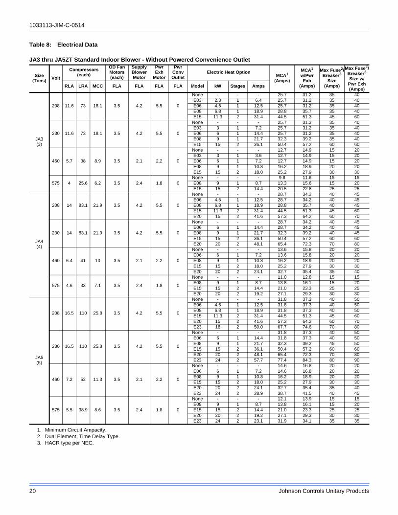
Table 8: Electrical Data
JA3 thru JA5ZT Standard Indoor Blower - Without Powered Convenience Outlet
Size(Tons)
Volt
Compressors(each)
OD FanMotors(each)
SupplyBlowerMotor
PwrExh
Motor
PwrConvOutlet
Electric Heat OptionMCA1
(Amps)
1. Minimum Circuit Ampacity.
MCA1
w/PwrExh
(Amps)
Max Fuse2/Breaker3
Size(Amps)
2. Dual Element, Time Delay Type.3. HACR type per NEC.
Max Fuse2/Breaker3 Size w/
Pwr Exh(Amps)
RLA LRA MCC FLA FLA FLA FLA Model kW Stages Amps
JA3(3)
208 11.6 73 18.1 3.5 4.2 5.5 0
None - - - 25.7 31.2 35 40E03 2.3 1 6.4 25.7 31.2 35 40E06 4.5 1 12.5 25.7 31.2 35 40E08 6.8 1 18.9 28.8 35.7 35 40E15 11.3 2 31.4 44.5 51.3 45 60
230 11.6 73 18.1 3.5 4.2 5.5 0
None - - - 25.7 31.2 35 40E03 3 1 7.2 25.7 31.2 35 40E06 6 1 14.4 25.7 31.2 35 40E08 9 1 21.7 32.3 39.2 35 40E15 15 2 36.1 50.4 57.2 60 60
460 5.7 38 8.9 3.5 2.1 2.2 0
None - - - 12.7 14.9 15 20E03 3 1 3.6 12.7 14.9 15 20E06 6 1 7.2 12.7 14.9 15 20E08 9 1 10.8 16.2 18.9 20 20E15 15 2 18.0 25.2 27.9 30 30
575 4 25.6 6.2 3.5 2.4 1.8 0None - - - 9.8 11.6 15 15E08 9 1 8.7 13.3 15.6 15 20E15 15 2 14.4 20.5 22.8 25 25
JA4(4)
208 14 83.1 21.9 3.5 4.2 5.5 0
None - - - 28.7 34.2 40 45E06 4.5 1 12.5 28.7 34.2 40 45E08 6.8 1 18.9 28.8 35.7 40 45E15 11.3 2 31.4 44.5 51.3 45 60E20 15 2 41.6 57.3 64.2 60 70
230 14 83.1 21.9 3.5 4.2 5.5 0
None - - - 28.7 34.2 40 45E06 6 1 14.4 28.7 34.2 40 45E08 9 1 21.7 32.3 39.2 40 45E15 15 2 36.1 50.4 57.2 60 60E20 20 2 48.1 65.4 72.3 70 80
460 6.4 41 10 3.5 2.1 2.2 0
None - - - 13.6 15.8 20 20E06 6 1 7.2 13.6 15.8 20 20E08 9 1 10.8 16.2 18.9 20 20E15 15 2 18.0 25.2 27.9 30 30E20 20 2 24.1 32.7 35.4 35 40
575 4.6 33 7.1 3.5 2.4 1.8 0
None - - - 11.0 12.8 15 15E08 9 1 8.7 13.8 16.1 15 20E15 15 2 14.4 21.0 23.3 25 25E20 20 2 19.2 27.1 29.3 30 30
JA5(5)
208 16.5 110 25.8 3.5 4.2 5.5 0
None - - - 31.8 37.3 40 50E06 4.5 1 12.5 31.8 37.3 40 50E08 6.8 1 18.9 31.8 37.3 40 50E15 11.3 2 31.4 44.5 51.3 45 60E20 15 2 41.6 57.3 64.2 60 70E23 18 2 50.0 67.7 74.6 70 80
230 16.5 110 25.8 3.5 4.2 5.5 0
None - - - 31.8 37.3 40 50E06 6 1 14.4 31.8 37.3 40 50E08 9 1 21.7 32.3 39.2 45 50E15 15 2 36.1 50.4 57.2 60 60E20 20 2 48.1 65.4 72.3 70 80E23 24 2 57.7 77.4 84.3 80 90
460 7.2 52 11.3 3.5 2.1 2.2 0
None - - - 14.6 16.8 20 20E06 6 1 7.2 14.6 16.8 20 20E08 9 1 10.8 16.2 18.9 20 20E15 15 2 18.0 25.2 27.9 30 30E20 20 2 24.1 32.7 35.4 35 40E23 24 2 28.9 38.7 41.5 40 45
575 5.5 38.9 8.6 3.5 2.4 1.8 0
None - - - 12.1 13.9 15 15E08 9 1 8.7 13.8 16.1 15 20E15 15 2 14.4 21.0 23.3 25 25E20 20 2 19.2 27.1 29.3 30 30E23 24 2 23.1 31.9 34.1 35 35
1033113-JIM-C-0514
Johnson Controls Unitary Products 21
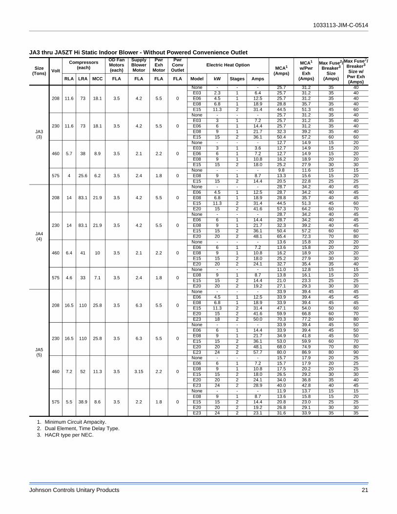
JA3 thru JA5ZT Hi Static Indoor Blower - Without Powered Convenience Outlet
Size(Tons)
Volt
Compressors(each)
OD FanMotors(each)
SupplyBlowerMotor
PwrExh
Motor
PwrConvOutlet
Electric Heat OptionMCA1
(Amps)
1. Minimum Circuit Ampacity.
MCA1
w/PwrExh
(Amps)
Max Fuse2/Breaker3
Size(Amps)
2. Dual Element, Time Delay Type.3. HACR type per NEC.
Max Fuse2/Breaker3 Size w/
Pwr Exh(Amps)
RLA LRA MCC FLA FLA FLA FLA Model kW Stages Amps
JA3(3)
208 11.6 73 18.1 3.5 4.2 5.5 0
None - - - 25.7 31.2 35 40E03 2.3 1 6.4 25.7 31.2 35 40E06 4.5 1 12.5 25.7 31.2 35 40E08 6.8 1 18.9 28.8 35.7 35 40E15 11.3 2 31.4 44.5 51.3 45 60
230 11.6 73 18.1 3.5 4.2 5.5 0
None - - - 25.7 31.2 35 40E03 3 1 7.2 25.7 31.2 35 40E06 6 1 14.4 25.7 31.2 35 40E08 9 1 21.7 32.3 39.2 35 40E15 15 2 36.1 50.4 57.2 60 60
460 5.7 38 8.9 3.5 2.1 2.2 0
None - - - 12.7 14.9 15 20E03 3 1 3.6 12.7 14.9 15 20E06 6 1 7.2 12.7 14.9 15 20E08 9 1 10.8 16.2 18.9 20 20E15 15 2 18.0 25.2 27.9 30 30
575 4 25.6 6.2 3.5 2.4 1.8 0None - - - 9.8 11.6 15 15E08 9 1 8.7 13.3 15.6 15 20E15 15 2 14.4 20.5 22.8 25 25
JA4(4)
208 14 83.1 21.9 3.5 4.2 5.5 0
None - - - 28.7 34.2 40 45E06 4.5 1 12.5 28.7 34.2 40 45E08 6.8 1 18.9 28.8 35.7 40 45E15 11.3 2 31.4 44.5 51.3 45 60E20 15 2 41.6 57.3 64.2 60 70
230 14 83.1 21.9 3.5 4.2 5.5 0
None - - - 28.7 34.2 40 45E06 6 1 14.4 28.7 34.2 40 45E08 9 1 21.7 32.3 39.2 40 45E15 15 2 36.1 50.4 57.2 60 60E20 20 2 48.1 65.4 72.3 70 80
460 6.4 41 10 3.5 2.1 2.2 0
None - - - 13.6 15.8 20 20E06 6 1 7.2 13.6 15.8 20 20E08 9 1 10.8 16.2 18.9 20 20E15 15 2 18.0 25.2 27.9 30 30E20 20 2 24.1 32.7 35.4 35 40
575 4.6 33 7.1 3.5 2.4 1.8 0
None - - - 11.0 12.8 15 15E08 9 1 8.7 13.8 16.1 15 20E15 15 2 14.4 21.0 23.3 25 25E20 20 2 19.2 27.1 29.3 30 30
JA5(5)
208 16.5 110 25.8 3.5 6.3 5.5 0
None - - - 33.9 39.4 45 45E06 4.5 1 12.5 33.9 39.4 45 45E08 6.8 1 18.9 33.9 39.4 45 45E15 11.3 2 31.4 47.1 54.0 50 60E20 15 2 41.6 59.9 66.8 60 70E23 18 2 50.0 70.3 77.2 80 80
230 16.5 110 25.8 3.5 6.3 5.5 0
None - - - 33.9 39.4 45 50E06 6 1 14.4 33.9 39.4 45 50E08 9 1 21.7 34.9 41.8 45 50E15 15 2 36.1 53.0 59.9 60 70E20 20 2 48.1 68.0 74.9 70 80E23 24 2 57.7 80.0 86.9 80 90
460 7.2 52 11.3 3.5 3.15 2.2 0
None - - - 15.7 17.9 20 25E06 6 1 7.2 15.7 17.9 20 25E08 9 1 10.8 17.5 20.2 20 25E15 15 2 18.0 26.5 29.2 30 30E20 20 2 24.1 34.0 36.8 35 40E23 24 2 28.9 40.0 42.8 40 45
575 5.5 38.9 8.6 3.5 2.2 1.8 0
None - - - 11.9 13.7 15 15E08 9 1 8.7 13.6 15.8 15 20E15 15 2 14.4 20.8 23.0 25 25E20 20 2 19.2 26.8 29.1 30 30E23 24 2 23.1 31.6 33.9 35 35

1033113-JIM-C-0514
22 Johnson Controls Unitary Products
JA3 thru JA5ZT Standard Indoor Blower - With Powered Convenience Outlet
Size(Tons)
Volt
Compressors(each)
OD FanMotors(each)
SupplyBlowerMotor
PwrExh
Motor
PwrConvOutlet
Electric Heat OptionMCA1
(Amps)
1. Minimum Circuit Ampacity.
MCA1
w/PwrExh
(Amps)
Max Fuse2/Breaker3
Size(Amps)
2. Dual Element, Time Delay Type.3. HACR type per NEC.
Max Fuse2/Breaker3 Size w/
Pwr Exh(Amps)
RLA LRA MCC FLA FLA FLA FLA Model kW Stages Amps
JA3(3)
208 11.6 73 18.1 3.5 4.2 5.5 10
None - - - 35.7 41.2 45 50E03 2.3 1 6.4 35.7 41.2 45 50E06 4.5 1 12.5 35.7 41.2 45 50E08 6.8 1 18.9 41.3 48.2 45 50E15 11.3 2 31.4 57.0 63.8 60 70
230 11.6 73 18.1 3.5 4.2 5.5 10
None - - - 35.7 41.2 45 50E03 3 1 7.2 35.7 41.2 45 50E06 6 1 14.4 35.8 42.7 45 50E08 9 1 21.7 44.8 51.7 45 60E15 15 2 36.1 62.9 69.7 70 70
460 5.7 38 8.9 3.5 2.1 2.2 5
None - - - 17.7 19.9 20 25E03 3 1 3.6 17.7 19.9 20 25E06 6 1 7.2 17.9 20.6 20 25E08 9 1 10.8 22.4 25.2 25 30E15 15 2 18.0 31.4 34.2 35 35
575 4 25.6 6.2 3.5 2.4 1.8 4None - - - 13.8 15.6 15 20E08 9 1 8.7 18.3 20.6 20 25E15 15 2 14.4 25.5 27.8 30 30
JA4(4)
208 14 83.1 21.9 3.5 4.2 5.5 10
None - - - 38.7 44.2 50 50E06 4.5 1 12.5 38.7 44.2 50 50E08 6.8 1 18.9 41.3 48.2 50 50E15 11.3 2 31.4 57.0 63.8 60 70E20 15 2 41.6 69.8 76.7 70 80
230 14 83.1 21.9 3.5 4.2 5.5 10
None - - - 38.7 44.2 50 50E06 6 1 14.4 38.7 44.2 50 50E08 9 1 21.7 44.8 51.7 50 60E15 15 2 36.1 62.9 69.7 70 70E20 20 2 48.1 77.9 84.8 80 90
460 6.4 41 10 3.5 2.1 2.2 5
None - - - 18.6 20.8 25 25E06 6 1 7.2 18.6 20.8 25 25E08 9 1 10.8 22.4 25.2 25 30E15 15 2 18.0 31.4 34.2 35 35E20 20 2 24.1 38.9 41.7 40 45
575 4.6 33 7.1 3.5 2.4 1.8 4
None - - - 15.0 21.0 15 20E08 9 1 8.7 18.8 21.1 20 25E15 15 2 14.4 26.0 28.3 30 30E20 20 2 19.2 32.1 34.3 35 35
JA5(5)
208 16.5 110 25.8 3.5 4.2 5.5 10
None - - - 41.8 47.3 50 60E06 4.5 1 12.5 41.8 47.3 50 60E08 6.8 1 18.9 41.8 48.2 50 60E15 11.3 2 31.4 57.0 63.8 60 70E20 15 2 41.6 69.8 76.7 70 80E23 18 2 50.0 80.2 87.1 90 90
230 16.5 110 25.8 3.5 4.2 5.5 10
None - - - 41.8 47.3 50 60E06 6 1 14.4 41.8 47.3 50 60E08 9 1 21.7 44.8 51.7 50 60E15 15 2 36.1 62.9 69.7 70 70E20 20 2 48.1 77.9 84.8 80 90E23 24 2 57.7 89.9 96.8 90 100
460 7.2 52 11.3 3.5 2.1 2.2 5
None - - - 19.6 21.8 25 25E06 6 1 7.2 19.6 21.8 25 25E08 9 1 10.8 22.4 25.2 25 30E15 15 2 18.0 31.4 34.2 35 35E20 20 2 24.1 38.9 41.7 40 45E23 24 2 28.9 45.0 47.7 45 50
575 5.5 38.9 8.6 3.5 2.4 1.8 4
None - - - 16.1 17.9 20 20E08 9 1 8.7 18.8 21.1 20 25E15 15 2 14.4 26.0 28.3 30 30E20 20 2 19.2 32.1 34.3 35 35E23 24 2 23.1 36.9 39.1 40 40

1033113-JIM-C-0514
Johnson Controls Unitary Products 23
JA3 thru JA5ZT Hi Static Blower - With Powered Convenience Outlet
Size(Tons)
Volt
Compressors(each)
OD FanMotors(each)
SupplyBlowerMotor
PwrExh
Motor
PwrConvOutlet
Electric Heat OptionMCA1
(Amps)
1. Minimum Circuit Ampacity.
MCA1
w/PwrExh
(Amps)
Max Fuse2/Breaker3
Size(Amps)
2. Dual Element, Time Delay Type.3. HACR type per NEC.
Max Fuse2/Breaker3 Size w/
Pwr Exh(Amps)
RLA LRA MCC FLA FLA FLA FLA Model kW Stages Amps
JA3(3)
208 11.6 73 18.1 3.5 4.2 5.5 10
None - - - 35.7 41.2 45 50E03 2.3 1 6.4 35.7 41.2 45 50E06 4.5 1 12.5 35.7 41.2 45 50E08 6.8 1 18.9 41.3 48.2 45 50E15 11.3 2 31.4 57.0 63.8 60 70
230 11.6 73 18.1 3.5 4.2 5.5 10
None - - - 35.7 41.2 45 50E03 3 1 7.2 35.7 41.2 45 50E06 6 1 14.4 35.8 42.7 45 50E08 9 1 21.7 44.8 51.7 45 60E15 15 2 36.1 62.9 69.7 70 70
460 5.7 38 8.9 3.5 2.1 2.2 5
None - - - 17.7 19.9 20 25E03 3 1 3.6 17.7 19.9 20 25E06 6 1 7.2 17.9 20.6 20 25E08 9 1 10.8 22.4 25.2 25 30E15 15 2 18.0 31.4 34.2 35 35
575 4 25.6 6.2 3.5 2.4 1.8 4None - - - 13.8 15.6 15 20E08 9 1 8.7 18.3 20.6 20 25E15 15 2 14.4 25.5 27.8 30 30
JA4(4)
208 14 83.1 21.9 3.5 4.2 5.5 10
None - - - 38.7 44.2 50 50E06 4.5 1 12.5 38.7 44.2 50 50E08 6.8 1 18.9 41.3 48.2 50 50E15 11.3 2 31.4 57.0 63.8 60 70E20 15 2 41.6 69.8 76.7 70 80
230 14 83.1 21.9 3.5 4.2 5.5 10
None - - - 38.7 44.2 50 50E06 6 1 14.4 38.7 44.2 50 50E08 9 1 21.7 44.8 51.7 50 60E15 15 2 36.1 62.9 69.7 70 70E20 20 2 48.1 77.9 84.8 80 90
460 6.4 41 10 3.5 2.1 2.2 5
None - - - 18.6 20.8 25 25E06 6 1 7.2 18.6 20.8 25 25E08 9 1 10.8 22.4 25.2 25 30E15 15 2 18.0 31.4 34.2 35 35E20 20 2 24.1 38.9 41.7 40 45
575 4.6 33 7.1 3.5 2.4 1.8 4
None - - - 15.0 21.0 15 20E08 9 1 8.7 18.8 21.1 20 25E15 15 2 14.4 26.0 28.3 30 30E20 20 2 19.2 32.1 34.3 35 35
JA5(5)
208 16.5 110 25.8 3.5 6.3 5.5 10
None - - - 43.9 49.4 60 60E06 4.5 1 12.5 43.9 49.4 60 60E08 6.8 1 18.9 44.0 50.8 60 60E15 11.3 2 31.4 59.6 66.5 70 70E20 15 2 41.6 72.4 79.3 80 80E23 18 2 50.0 82.8 89.7 90 90
230 16.5 110 25.8 3.5 6.3 5.5 10
None - - - 43.9 49.4 60 60E06 6 1 14.4 43.9 49.4 60 60E08 9 1 21.7 47.4 54.3 60 60E15 15 2 36.1 65.5 72.4 70 80E20 20 2 48.1 80.5 87.4 90 90E23 24 2 57.7 92.5 99.4 100 100
460 7.2 52 11.3 3.5 3.15 2.2 5
None - - - 20.7 22.9 25 30E06 6 1 7.2 20.7 22.9 25 30E08 9 1 10.8 23.7 26.5 25 30E15 15 2 18.0 32.7 35.5 35 40E20 20 2 24.1 40.3 43.0 45 45E23 24 2 28.9 46.3 49.0 50 50
575 5.5 38.9 8.6 3.5 2.2 1.8 4
None - - - 15.9 17.7 20 20E08 9 1 8.7 18.6 20.8 20 25E15 15 2 14.4 25.8 28.0 30 30E20 20 2 19.2 31.8 34.1 35 35E23 24 2 23.1 36.6 38.9 40 40

1033113-JIM-C-0514
24 Johnson Controls Unitary Products
Table 9: Physical Data
JA3 thru JA5ZT Single Stage Gas Heat Physical Data
ComponentModels
JA3ZT JA4ZT JA5ZT
Nominal Tonnage 3.0 4.0 5.0
AHRI COOLING PERFORMANCE
Gross Capacity @ AHRI A point (MBh) 39000 54000 66000
AHRI net capacity (MBh) 38000 52000 64000
EER 14.15 14.35 13.85
SEER 18.1 18 17.5
IPLV - - -
Nominal CFM 1200 1600 2000
System power (KW) 2.70 3.64 4.62
Refrigerant type R-410A R-410A R-410A
Refrigerant charge (lb-oz)
System 1 9-12 13-2 12-7
System 2 - - -
AHRI HEATING PERFORMANCE
Heating model A05 A07 A09 A05 A07 A09 A07 A09 A13
Heat input (K Btu) 60 80 120 60 80 120 80 120 160
Heat output (K Btu) 49 65 97 49 65 97 65 97 129
AFUE % - - - - - -
Steady state efficiency (%) 81.5 81 81 81.5 81 81 81 81 80.5
No. burners 4 4 6 4 4 6 4 6 8
No. stages 1 1 1 1 1 1 1 1 1
Temperature Rise Range (ºF) 20-50°F 25-65°F 35-80°F 20-50°F 25-65°F 35-80°F 25-65°F 35-80°F 45-75°F
Gas Limit Setting (ºF) 200 235 290 200 235 290 235 290 240
Gas piping connection (in.) 3/4 3/4 3/4 3/4 3/4 3/4 3/4 3/4 3/4
DIMENSIONS (inches)
Length 89 89 89
Width 59 59 59
Height 42 42 42
OPERATING WT. (lbs.) 922 960 968
COMPRESSORS
Type 2-stage scroll 2-stage scroll 2-stage scroll
Quantity 1 1 1
Unit Capacity Steps (%) 67/100 67/100 67/100
CONDENSER COIL DATA
Face area (Sq. Ft.) 12.2 12.2 12.2
Rows 1 1 1
Fins per inch 23 23 23
Tube diameter (in./MM) .98/25 .98/25 .98/25
Circuitry Type 2-pass Microchannel 2-pass Microchannel 2-pass Microchannel
EVAPORATOR COIL DATA
Face area (Sq. Ft.) 10.56 10.56 10.56
Rows 3 4 4
Fins per inch 15 15 15
Tube diameter 0.375 0.375 0.375
Refrigerant control TXV TXV TXV

1033113-JIM-C-0514
Johnson Controls Unitary Products 25
CONDENSER FAN DATA
Quantity of fans 2 2 2
Fan diameter (Inch) 24 24 24
Type Prop Prop Prop
Drive type Direct ECM Direct ECM Direct ECM
Quantity of motors 2 2 2
Motor HP each 1/3 1/3 1/3
No. speeds Var. Var. Var.
RPM 850 850 850
Nominal total CFM 7000 7000 7000
BELT DRIVE EVAP FAN DATA
Quantity 1 1 1
Fan Size (Inch) 12 x 9 12 x 9 12 x 9
Type Centrifugal Centrifugal Centrifugal
Motor Sheave 1VL40 1VL40 1VL34 1VL44 1VL40 1VM50
Blower Sheave AK79 AK61 AK64 AK69 AK61 AK64
Belt A47 A45 A47 A47 A45 A47
Motor HP each 1-1/2 1-1/2 1-1/2 1-1/2 1-1/2 2
RPM 1725 1725 1725 1725 1725 1725
Frame size 56 56 56 56 56 56
FILTERS
Quantity - Size4 - (24 x 16 x 2)1,2 4 - (24 x 16 x 2)1,2 4 - (24 x 16 x 2)1,2
4 - (24 x 16 x 4)3 4 - (24 x 16 x 4)3 4 - (24 x 16 x 4)3
1. 2 In. Throwaway, Standard, MERV (Minimum Efficiency Reporting Value) 2. 2 In. Pleated, Optional, MERV 7.3. 4 In. Pleated, Optional, MERV 13.
JA3 thru JA5ZT Single Stage Gas Heat Physical Data (Continued)
ComponentModels
JA3ZT JA4ZT JA5ZT
Nominal Tonnage 3.0 4.0 5.0

1033113-JIM-C-0514
26 Johnson Controls Unitary Products
JA3 thru JA5ZT Two Stage Gas Heat Physical Data
ComponentModels
JA3ZT JA4ZT JA5ZT
Nominal Tonnage 3.0 4.0 5.0
AHRI COOLING PERFORMANCE
Gross Capacity @ AHRI A point (MBh) 39000 54000 66000
AHRI net capacity (MBh) 38000 52000 64000
EER 14.15 14.35 13.85
SEER 18.1 18 17.5
IPLV - - -
Nominal CFM 1200 1600 2000
System power (KW) 2.70 3.64 4.62
Refrigerant type R-410A R-410A R-410A
Refrigerant charge (lb-oz)
System 1 9-12 13-2 12-7
System 2 - - -
AHRI HEATING PERFORMANCE
Heating model N05 N07 N09 N05 N07 N09 N07 N09 N13
Heat input (K Btu) 60 80 120 60 80 120 80 120 160
Heat output (K Btu) 49 65 97 49 65 97 65 97 129
AFUE % - - - - - -
Steady state efficiency (%) 81.5 81 81 81.5 81 81 81 81 80.5
No. burners 4 4 6 4 4 6 4 6 8
No. stages 21 22 22 21 22 22 22 22 22
Temperature Rise Range (ºF) 20-50°F 25-65°F 35-80°F 20-50°F 25-65°F 35-80°F 25-65°F 35-80°F 45-75°F
Gas Limit Setting (ºF) 200 235 290 200 235 290 235 290 240
Gas piping connection (in.) 3/4 3/4 3/4 3/4 3/4 3/4 3/4 3/4 3/4
DIMENSIONS (inches)
Length 89 89 89
Width 59 59 59
Height 42 42 42
OPERATING WT. (lbs.) 922 960 968
COMPRESSORS
Type 2-stage scroll 2-stage scroll 2-stage scroll
Quantity 1 1 1
Unit Capacity Steps (%) 67/100 67/100 67/100
CONDENSER COIL DATA
Face area (Sq. Ft.) 12.2 12.2 12.2
Rows 1 1 1
Fins per inch 23 23 23
Tube diameter (in./MM) .98/25 .98/25 .98/25
Circuitry Type 2-pass Microchannel 2-pass Microchannel 2-pass Microchannel
EVAPORATOR COIL DATA
Face area (Sq. Ft.) 10.56 10.56 10.56
Rows 3 4 4
Fins per inch 15 15 15
Tube diameter 0.375 0.375 0.375
Refrigerant control TXV TXV TXV

1033113-JIM-C-0514
Johnson Controls Unitary Products 27
1. 1st Stage Capacity is 75% of Full Capacity.2. 1st Stage Capacity is 70% of Full Capacity.3. 2 In. Throwaway, Standard, MERV (Minimum Efficiency Reporting Value) 3.4. 2 In. Pleated, Optional, MERV 7.5. 4 In. Pleated, Optional, MERV 13.
Optional Electric Heat
The factory-installed heaters are wired for single point power supply. Power supply need only be brought into the single point terminal block.
These CSA approved heaters are located within the central compartment of the unit with the heater elements extending in to the supply air chamber.
Fuses are supplied, where required, by the factory. Some kW sizes require fuses and others do not. refer to Table 10 for minimum CFM limitations and to Table 8 for electrical data.
CONDENSER FAN DATA
Quantity of fans 2 2 2
Fan diameter (Inch) 24 24 24
Type Prop Prop Prop
Drive type Direct ECM Direct ECM Direct ECM
Quantity of motors 2 2 2
Motor HP each 1/3 1/3 1/3
No. speeds Var. Var. Var.
RPM 850 850 850
Nominal total CFM 7000 7000 7000
BELT DRIVE EVAP FAN DATA
Quantity 1 1 1
Fan Size (Inch) 12 x 9 12 x 9 12 x 9
Type Centrifugal Centrifugal Centrifugal
Motor Sheave 1VL40 1VL40 1VL34 1VL44 1VL40 1VM50
Blower Sheave AK79 AK61 AK64 AK69 AK61 AK64
Belt A47 A45 A47 A47 A45 A47
Motor HP each 1-1/2 1-1/2 1-1/2 1-1/2 1-1/2 2
RPM 1725 1725 1725 1725 1725 1725
Frame size 56 56 56 56 56 56
FILTERS
Quantity - Size4 - (24 x 16 x 2)3,4 4 - (24 x 16 x 2)3,4 4 - (24 x 16 x 2)3,4
4 - (24 x 16 x 4)5 4 - (24 x 16 x 4)5 4 - (24 x 16 x 4)5
JA3 thru JA5ZT Two Stage Gas Heat Physical Data (Continued)
ComponentModels
JA3ZT JA4ZT JA5ZT
Nominal Tonnage 3.0 4.0 5.0
Table 10: Electric Heat Minimum Supply Air
Size(Tons)
Model VoltageMinimum Supply Air (CFM)
Heater kW3 6 9 15 20 24
JA3(3)
J**ZT208/230-3-60 960 960 1020 1000 - -
460-3-60 980 960 960 960 - -600-3-60 - - 960 960 - -
JA4(4)
J**ZT208/230-3-60 - 1280 1420 1400 1400 -
460-3-60 - 1400 1400 1400 1400 -600-3-60 - - 1400 1400 1400 -
JA5(5)
J**ZT208/230-3-60 - 1600 1600 1600 1600 1600
460-3-60 - 1600 1600 1600 1600 1600600-3-60 - - 1600 1600 1600 1600

1033113-JIM-C-0514
28 Johnson Controls Unitary Products
Optional Gas Heat
These gas-fired heaters have aluminized-steel or optional stainless steel, tubular heat exchangers with spark ignition.
Gas Piping
Proper sizing of gas piping depends on the cubic feet per hour of gas flow required, specific gravity of the gas and the length of run. "National Fuel Gas Code" Z223.1 (in U.S.A.) or the current Gas Installation Codes CSA-B149.1 (in Canada) should be followed in all cases unless superseded by local codes or gas utility requirements. Refer to the Pipe Sizing Table 11. The heating value of the gas may differ with locality. The value should be checked with the local gas utility.
Figure 21: Side Entry Gas Piping
Figure 22: Bottom Entry Gas Piping
NOTE: Maximum capacity of pipe in cubic feet of gas per hour based upon a pressure drop of 0.3 inch W.C. and 0.6 specific gravity gas.
NOTE: There may be a local gas utility requirement specifying a minimum diameter for gas piping. All units require a 3/4 inch pipe connection at the entrance fitting. Line should not be sized smaller than the entrance fitting size.
OPTIONAL COIL GUARDSHOWN
Table 11: Gas Pipe Sizing - Capacity of Pipe
Length of Pipe (ft.)
Nominal Iron Pipe Size
3/4 in. 1 in. 1-1/4 in.
10 278 520 1050
20 190 350 730
30 152 285 590
40 130 245 500
50 115 215 440
60 105 195 400
70 96 180 370
80 90 170 350
90 84 160 320
100 79 150 305
OPTIONALCOIL GUARDSHOWN

1033113-JIM-C-0514
Johnson Controls Unitary Products 29
Gas Connection
The gas supply line can be routed within the space and roof curb, exiting through the unit’s basepan. Refer to Figures and 9 for the gas piping inlet location. Typical supply piping arrangements are shown in Figures 21 and 22. All pipe nipples, fittings, and the gas cock are field supplied or may be purchased in UP accessory kit #1GP0405.
Gas piping recommendations:
1. A drip leg and a ground joint union must be installed in the gas piping.
2. Where required by local codes, a manual shut-off valve must be installed outside of the unit.
3. Use wrought iron or steel pipe for all gas lines. Pipe dope should be applied sparingly to male threads only.
4. All piping should be cleaned of dirt and scale by hammering on the outside of the pipe and blowing out loose particles. Before initial start-up, be sure that all gas lines external to the unit have been purged of air.
5. The gas supply should be a separate line and installed in accordance with all safety codes as prescribed under “Limitations”.
6. A 1/8-inch NPT plugged tapping, accessible for test gage connection, must be installed immediately upstream of the gas supply connection to the unit.
7. After the gas connections have been completed, open the main shut-off valve admitting normal gas pressure to the mains. Check all joints for leaks with soap solution or other material suitable for the purpose. NEVER USE A FLAME.
LP Units, Tanks And Piping
All gas heat units are shipped from the factory equipped for natural gas use only. The unit may be converted in the field for use with LP gas with accessory kit model numbers 1NP0454 or 1NP0455.
All LP gas equipment must conform to the safety standards of the National Fire Protection Association.
Table 12: Gas Heat Minimum Supply Air
Size(Tons)
Model Heat SizeSupply Air (CFM)
HeatingMin Max
JA3(3)
J**ZTA05 / N05 890 2220A07 / N07 915 2370A09 / N09 1130 1800
JA4(4)
J**ZTA05 / N05 890 2220A07 / N07 915 2370A09 / N09 1290 2250
JA5(5)
J**ZTA07 / N07 915 2370A09 / N09 1380 2570A13 / N13 1580 2630
Natural gas may contain some propane. Propane is an excellent solvent and will quickly dissolve white lead and most standard commercial compounds. A special pipe dope must be used when assembling wrought iron or steel pipe. Shellac based compounds such as Gaskolac or Stalastic, and compounds such as Rectorseal #5, Clydes’s or John Crane may be used.
FIRE OR EXPLOSION HAZARD
Failure to follow the safety warning exactly could result in serious injury, death or property damage.
Never test for gas leaks with an open flame. use a commercially available soap solution made specifically for the detection of leaks to check all connections. A fire or explosion may result causing property damage, personal injury or loss of life.
The furnace and its individual shut-off valve must be disconnected from the gas supply piping system during any pressure testing at pressures in excess of 1/2 PSIG.
Pressures greater than 1/2 PSIG will cause gas valve damage resulting in a hazardous condition. If it is subjected to a pressure greater than 1/2 PSIG, the gas valve must be replaced.
The furnace must be isolated from the gas supply piping system by closing its individual manual shut-off valve during any pressure testing of the gas supply piping system at test pressures equal to or less than 1/2 PSIG.
Threaded joints should be coated with a sealing compound that is resistant to the action of liquefied petroleum gases. Do not use Teflon tape.

1033113-JIM-C-0514
30 Johnson Controls Unitary Products
For satisfactory operation, LP gas pressure must be 10.5 inch W.C. at the unit under full load. Maintaining proper gas pressure depends on three main factors:
1. The vaporization rate which depends on the temperature of the liquid and the “wetted surface” area of the container(s).
2. The proper pressure regulation. (Two-stage regulation is recommended).
3. The pressure drop in the lines between regulators and between the second stage regulator and the appliance. Pipe size required will depend on the length of the pipe run and the total load of all appliances.
Complete information regarding tank sizing for vaporization, recommended regulator settings, and pipe sizing is available from most regulator manufacturers and LP gas suppliers.
Check all connections for leaks when piping is completed using a soap solution. NEVER USE A FLAME.
Vent And Combustion Air
Venting slots in the heating compartment access panel remove the need for a combustion air hood. The gas heat flue exhaust is routed through factory installed exhaust piping with screen. If necessary, a flue exhaust extension may be installed at the point of installation.
Options/Accessories
Electric Heat
Electric heaters are available as factory-installed options or field-installed accessories. Refer to electric heat instructions for
installation. These heaters mount in the heat compartment with the heating elements extending into the supply air chamber. All electric heaters are fused and intended for use with single point power supply.
Smoke Detectors
The factory-installed smoke detector will shut down operation of the unit by interrupting power to the UCB when smoke is detected within its mounting compartment. The smoke detector option is available for both supply and/or return air configura-tions. Be aware that the supply air configuration has the sensor component mounted in the blower section, with its control mod-ule mounted in the return air compartment.
The detector must be tested and maintained on a regular basis according to NFPA 72 requirements and cleaned at least once a year. For specific troubleshooting and maintenance procedures, please refer to the smoke detector's installation instructions which accompanies the unit.
LP gas is an excellent solvent and will quickly dissolve white lead and most standard commercial compounds. A special pipe dope must be used when assembling wrought iron or steel pipe for LP. Shellac base compounds such as Gaskolac or Stalastic, and compounds such as Rectorseal #5, Clyde’s, or John Crane may be used.
FIRE OR EXPLOSION HAZARD
Failure to follow the safety warning exactly could result in serious injury, death or property damage.
Never test for gas leaks with an open flame. use a commercially available soap solution made specifically for the detection of leaks to check all connections. A fire or explosion may result causing property damage, personal injury or loss of life.
The use of duct smoke detectors have specific limitations as established by the National Fire Protection Association. Duct smoke detectors are; NOT a substitute for an open area smoke detector, NOT a substitute for early warning detection, and NOT a replacement for a building's regular fire detection system. Refer to NFPA Code 72 and Standard 90A for additional information.
Factory-installed smoke detectors may be subjected to extreme temperatures during "off" times due to outside air infiltration. These smoke detectors have an operational limit of -4°F to 158°F. Smoke detectors installed in areas that could be outside this range will have to be relocated to prevent false alarms.
To assure adequate airflow reaches the smoke detector's sensor, make sure that the holes of the sampling tube face into the air stream, and that the far-end of the sampling tube is sealed with the plastic end cap.
In addition, the unit's supply airflow must be adjusted to provide a pressure differential across the smoke detector's sampling and exhaust ports of at least 0.01 inches of water and no more than 1.11 inches of water, as measured by a manometer.

1033113-JIM-C-0514
Johnson Controls Unitary Products 31
Motorized Outdoor Damper
The Motorized Outdoor Damper can be a factory installed option or a field installed accessory. If factory installed, refer to the instructions included with the outdoor air hood to complete the assembly. Field installed Motorized Outdoor Damper accessories include complete instructions for installation.
Economizer
The Economizer can be a factory installed option or a field installed accessory. If factory installed, refer to the instructions included with the outdoor air hood to complete the assembly. Field installed Economizer accessories include complete instructions for installation.
There are two Economizer options:
1. Down Flow application with barometric relief hood standard.
2. Horizontal Flow application that requires the purchase of a barometric relief hood.
Power Exhaust
The Power Exhaust can be a factory installed option or a field installed accessory. If factory installed, refer to the instructions included with the outdoor air hood to complete the assembly. Field installed Power Exhaust accessories include complete instructions for installation.
The Power Exhaust factory installed option is for Down Flow application only.
There are two field installed Power Exhaust accessories:
1. Down Flow application.
2. Horizontal Flow application that requires the purchase of a barometric relief hood.
Rain Hood
All of the hood components, including the filters, the gasketing and the hardware for assembling, are packaged and located between the condenser coil section and the main unit cabinet, if the unit has factory installed options. If field installed accessories are being installed all parts necessary for the installation comes in the accessory.
INTELLI-Comfort II Control Board
The control board, located in the control box, is used to convert the pressure transducer input signal into a speed reference signal that the drive uses to control the speed of the blower motor. This modulating speed reference signal is generated using an algorithm which continuously calculates an output value.
A brief description of the board's I/O terminals that are used follows;
Inputs:
• DUCT PRES - a 0-5 VDC analog input provided by a factory-installed duct static pressure transducer located in the unit's control box.
• SAT - analog input provided by a factory-installed 10k-ohm, type 3 thermistor located in the unit's supply air compartment.
• RAT - analog input provided by a factory-installed 10k-ohm, type 3 thermistor located in the unit's return air compartment.
• OAT - analog input provided by a factory-installed 10k-ohm, type 3 thermistor located in the unit’s compressor compartment within the base rail.
• ST - analog input provided by field-installed space temperature sensor.
• OH - a 0-10 VDC analog input provided by a field installed outdoor air relative humidity sensor for single enthalpy economizer configuration.
• RH - a 0-10 VDC analog input provided by a field-installed return air relative humidity sensor for dual enthalpy economizer configuration (used with OH).
• IAQ - a 0-10 VDC analog input provided by a field-installed carbon dioxide sensor which monitors indoor air quality (CO2 concentration) and enables call for Demand Ventilation mode for units installed with economizer option.
• OAQ - a 0-10 VDC analog input provided by a field-installed carbon dioxide sensor which monitors outdoor air quality (CO2 concentration) and, along with IAQ, enables call for Differential Demand Ventilation mode for units installed with economizer option.
• APS - a 24 VAC binary input provided by a field-installed air proving switch which monitors the pressure difference across the indoor blower.
• PUR - a 24 VAC binary input for building purge calls from an external source.
• OCC - a 24 VAC binary input used to set the building occupancy status for the control.
• LIMIT 2 - a 24 VAC binary input which either confirms 2nd-stage gas heat operation or receives an error signal from the variable frequency drive.
Outputs:
• FAN - a 2-10 VDC analog output signal sent to the VFD to modulate the speed of the indoor blower motor.
• ECON - a 2-10 VDC analog output signal sent to the economizer actuator to modulate position of the return air and outdoor air dampers (optional).
• EXH ~ - a 24 VAC binary output signal used to turn on/off the power exhaust relay (optional).
Factory-installed VFD (Standard)
The factory-installed VFD is mounted in the blower access compartment. The drive comes wired from the factory to include both 3-phase power and control connections (run permit signal, speed reference signal & fault signal). All required drive parameters are pre-programmed at the factory, except in the case of 208-volt applications, in which the parameter that defines motor nameplate voltage must be changed to a value of

1033113-JIM-C-0514
32 Johnson Controls Unitary Products
208.00 and the parameter that defines motor-rated current must be changed to the appropriate value appearing on the motor's nameplate. Refer to the enclosed drive material or access the UPGnet Commercial Product Catalog website for instructions on changing parameter settings.
Manual Bypass
An optional, factory-installed manual bypass switch available with factory-installed VFD can be found in the Blower Motor Access compartment and has the following three positions:
• DRIVE - routes power through the VFD for modulating control of the indoor blower motor.
• LINE (or BYPASS) - routes power directly to the motor which provides full-speed motor operation and complete electrical isolation of the drive.
• TEST - routes power to the VFD but not to the motor to allow for drive programming and/or diagnostics.
If a drive failure occurs, the unit does not automatically switch to bypass mode. The LINE/DRIVE/TEST switch must be manually switched to the LINE (BYPASS) position. If there is a call for the fan, the indoor blower motor will run at full-speed while in the bypass mode.
Figure 23: Simplified VFD Wiring
Economizer Interface Overview
This section describes how to use the Economizer’s user interface for:
• Keypad and menu navigation
• Settings and parameter changes
• Menu structure and selection
User Interface
The user interface consists of an LCD display and a 4-button keypad on the front of the Economizer module. The LCD is a 16 character by 2 line dot matrix display.
Figure 24: Economizer LCD and Keypad Layout.
Keypad
The four navigation buttons illustrated in Fig. 24 are used to scroll through the menus and menu items, select menu items, and to change parameter and configuration settings.
Using the Keypad with Menus
To use the keypad when working with menus:
• Press the button to move to the previous menu.
• Press the button to move to the next menu.
Before beginning any service, disconnect all power to the drive. Be aware that high voltages are present in the drive even after power has been disconnected. Capacitors within the drive must be allowed to discharge before beginning service.
Do not connect AC power to the T1, T2, T3 drive terminals to prevent damage to the VFD.
ELEMENTARY DIAGRAM
VFD
TB8 (IN CONTROL BOX)
RUN PERMIT(DIGITAL)
SPEED REF(ANALOG)(2-10 VDC)
GND
GRN
GND
GRNGND
1 DMTR118 / BK
119 / BR
120 / Y
3
M(T1)
(T2)
(T3)
( )
(L1)
(L3)
(L2)
722 / BK
725 / BR
728 / Y
720 / PR
723 / BR
726 / O
TB1FU3
FU5
FU4
1 2 3 4 5 6
L3
L2
L1 T1
T2
T3
The fuses (FU3, FU4, FU5) supplied with the unit are sized according to the electrical load of the blower motor, but may not provide adequate protection to the customer-installed drive, depending upon its specifications. Once a drive has been selected and installed, refer to the drive manufacturer's recommendations for proper fuse sizing.
MENU UP(EXIT)
BUTTONSCROLL
(UP/DOWN)BUTTONS
SELECT (ENTER)BUTTONS
2 LINELCD

1033113-JIM-C-0514
Johnson Controls Unitary Products 33
• Press the button (Enter) to display the first item in the currently displayed menu.
• Press the button (Menu up) to exit a menu’s item and return to the list of menus.
Using the Keypad with Settings and Parameters
To use the keypad when working with Setpoints, System and
Advanced Settings, Checkout tests, and Alarms:
• Navigate to the desired menu.
• Press the button (Enter) to display the first item in the currently displayed menu.
• Use the and buttons to scroll to the desired parameter.
• Press the button (Enter) to display the value of the
• Press the button to increase (change) the displayed parameter value.1
• Press the button to decrease (change) the displayed parameter value.
• Press the button to accept the displayed value and store it in non-volatile RAM.
• CHANGE STORED displays.
• Press the button (MenuUp/Exit) to return to the previous menu.
Menu Structure
The Menus in display order are:
• STATUS
• SETPOINTS
• SYSTEM SETUP
• ADVANCED SETUP
• CHECKOUT
• ALARMS
NOTE: Your menu parameters will be different depending on your configuration. See the JADE™ Economizer Module accessory instruction P/N 1150208-UAI-A-0514 included in this instruction packet for additional menu information.
Economizer Setup And Configuration
Before being placed into service, the JADE™ Economizer module must be setup and configured for the installed system.
NOTE: During setup, the Economizer module is live at all times.
The setup process uses a hierarchical menu structure that is easy to use. You press the and arrow buttons to move forward and backward through the menus and press the button to select and confirm setup item changes.
Time-out and Screensaver
When no buttons have been pressed for 10 minutes, the LCD displays a screen saver, which cycles through the Status items. Each Status items displays in turn and cycles to the next item after 5 seconds.
Figure 25: Single Enthalpy Curve And Boundaries
1. When values are displayed, pressing and holding the and button causes the display to automatically increment.
TEMPERATURE
RATE
MP
ABSO
LUTE
HU
MID
ITY
ES4ES5 ES3 ES2 ES1 HL
DUAL ENTHALPYHIGH LIMIT
ECONOMIZING
SINGLE ENTHALPY
AVAILABLE
NOT AVAILABLE
P2 (T,RH)
P1 (T,RH)
ENTHALPYRA HUM (%
RH)

1033113-JIM-C-0514
34 Johnson Controls Unitary Products
Enthalpy Settings
When the OA temperature, enthalpy and dew point are below the respective setpoints, the Outdoor Air can be used for economizing. Fig. 25 shows the new single enthalpy boundaries in the W7220. There are 5 boundaries (setpoints ES1 through ES5), which are defined by dry bulb temperature, enthalpy and dew point.
Refer to Table 13 for the ENTH CURVE setpoint values.
To use enthalpy the W7220 must have a C7400S Sylkbus sensor for OA. The W7220 calculates the enthalpy and dew point using the OA temperature and humidity input from the OA sensor. When the OA temperature, OA humidity and OA dew point are all below the selected boundary, the economizer sets the economizing mode to YES, economizing is available.
When conditions are above the selected boundary, the conditions are not good to economize and the mode is set to NO.
Fig. 25 shows the 5 current boundaries. There is also a high limit boundary for differential enthalpy. The high limit boundary is ES1 when there are no stages of mechanical cooling energized and HL when a compressor stage is energized.
Table 13 provides the values for each boundary limit.
Two-Speed Fan Operation
The later versions of the W7220 Jade controller have the capability to work with a system using a 2-speed supply fan. The W7220 does not control the supply directly but uses the following input status to determine the speed of the supply fan and controls the OA damper to the required position.
The W (heating mode) is not controlled by the W7220 but it requires the status to know where to position the OA damper for minimum position for the fan speed.
The 2 speed fan delay is available when the system is programmed for 2 speed fan (in the System Setup menu item). The 2 speed fan delay is defaulted to 5 minutes and can be changed in the Advanced Setup menu item. When the unit has a call for Y1 In and in the free cooling mode and there is a call for Y2 In, the 2-speed fan delay starts and the OA damper will modulate 100% open, the supply fan should be set to high speed by the unit controller. After the delay one of two actions will happen:
• The Y2 In call will be satisfied with the damper 100% open and fan on high speed and the call will turn off.
OR
• If the call for additional cooling in the space has not been satisfied then the first stage of mechanical cooling will be enabled through Y1 Out or Y2 Out.
Indoor Air Quality AQ
Indoor Air Quality (indoor sensor input): Terminal AQ accepts a +2 to +10 Vdc signal with respect to the (AQ1) terminal. When the signal is below it's set point, the actuator is allowed to modulate normally in accordance with the enthalpy and mixed air sensor inputs. When the AQ signal exceeds it's set point setting and there is no call for free cooling, the actuator is proportionately modulated from the 2 to 10 Vdc signal, with 2 Vdc corresponding to full closed and 10 Vdc corresponding to full open. When there is no call for free cooling, the damper position is limited by the IAQ Max damper position setting. When the signal exceeds it's set point (Demand Control Ventilation Set Point) setting and there is a call for free cooling, the actuator modulates from the minimum position to the full open position based on the highest call from either the mixed air sensor input or the AQ voltage input.
• Optional CO2 Space Sensor Kit Part # 2AQ04700324
• Optional CO2 Sensor Kit Part # 2AQ04700424
Replace the top rear access panel on the unit.
Phasing
Series 10 units are properly phased at the factory. Check for proper compressor rotation. If the blower or compressors rotate in the wrong direction at start-up, the electrical connection to the unit is misphased. Change the phasing of the Field Line
Table 13: Single Enthalpy and Dual Enthalpy High Limit Curves.
EnthalpyCurve
Temp.Dry-Bulb (°F)
Temp. Dewpoint (°F)
Enthalpy(btu/lb/da)
Point P1 Point P2
Temp. °F Humidity %RH Temp. °F Humidity %RH
ES1 80.0 60.0 28.0 80.0 36.8 66.3 80.1
ES2 75.0 57.0 26.0 75.0 39.6 63.3 80.0
ES3 70.0 54.0 24.0 70.0 42.3 59.7 81.4
ES4 65.0 51.0 22.0 65.0 44.8 55.7 84.2
ES5 60.0 48.0 20.0 60.0 46.9 51.3 88.5
HL 86.0 66.0 32.4 86.0 38.9 72.4 80.3
State Fan Speed
OCC Low
Y1 Low
Y2 High
W High

1033113-JIM-C-0514
Johnson Controls Unitary Products 35
Connection at the factory or field supplied disconnect to obtain proper rotation. (Scroll compressors operate in only one direction. If the scroll is drawing low amperage, has similar suction and discharge pressures, or producing a high noise level, the scroll is misphased.)
Blower Rotation
Check for proper supply air blower rotation. If the blower is rotating backwards, the line voltage at the unit point of power connection is misphased (See ‘PHASING’).
Belt Tension
The tension on the belt should be adjusted as shown in Figure 26.
Figure 26: Belt Adjustment
CFM Static Pressure and Power-Altitude and Temperature Corrections
The information below should be used to assist in application of product when being applied at altitudes at or exceeding 1000 feet above sea level.
The air flow rates listed in the standard blower performance tables are based on standard air at sea level. As the altitude or temperature increases, the density of air decreases. In order to use the indoor blower tables for high altitude applications, certain corrections are necessary.
A centrifugal fan is a "constant volume" device. This means that, if the rpm remains constant, the CFM delivered is the same regardless of the density of the air. However, since the air at high altitude is less dense, less static pressure will be generated and less power will be required than a similar application at sea level. Air density correction factors are shown in Table 15 and Figure 27.
Scroll compressors require proper rotation to operate correctly. Units are properly phased at the factory. Do not change the internal wiring to make the blower condenser fans, or compressor rotate correctly.
Table 14: Supply Air Limitations
Unit Size (Ton) Minimum Maximum
JA3 (3.0) 900 1500
JA4 (4.0) 1200 2000
JA5 (5.0) 1500 2500
A
A
A
B
SPAN LENGTH
DEFL. FORCE
C** NEVER LOOSEN
Procedure for adjusting belt tension:1. Loosen six nuts (top and bottom) A.2. Adjust by turning (B).3. Never loosen nuts (C).4. Use belt tension checker to apply a perpendicular
force to one belt at the midpoint of the span as shown. Deflection distance of 4mm (5/32”) is obtained.
To determine the deflection distance from normal position, use a straight edge from sheave to sheave as reference line. The recommended deflection force is as follows:Tension new belts at the max. deflection force recommended for the belt section. Check the belt tension at least two times during the first 24 hours of operation. Any retensioning should fall between the min. and max. deflection force values.5. After adjusting retighten nuts (A).

1033113-JIM-C-0514
36 Johnson Controls Unitary Products
Figure 27: Altitude/Temperature Correction Factors
The examples below will assist in determining the airflow performance of the product at altitude.
Example 1: What are the corrected CFM, static pressure, and BHP at an elevation of 5,000 ft. if the blower performance data is 6,000 CFM, 1.5 IWC and 4.0 BHP?
Solution: At an elevation of 5,000 ft. the indoor blower will still deliver 6,000 CFM if the rpm is unchanged. However, Table 14 must be used to determine the static pressure and BHP. Since no temperature data is given, we will assume an air temperature of 70°F. Table 16 shows the correction factor to be 0.832.
Corrected static pressure = 1.5 x 0.832 = 1.248 IWC
Corrected BHP = 4.0 x 0.832 = 3.328
Example 2: A system, located at 5,000 feet of elevation, is to deliver 6,000 CFM at a static pressure of 1.5". Use the unit
blower tables to select the blower speed and the BHP requirement.
Solution: As in the example above, no temperature information is given so 70°F is assumed.
The 1.5" static pressure given is at an elevation of 5,000 ft. The first step is to convert this static pressure to equivalent sea level conditions.
Sea level static pressure = 1.5 / .832 = 1.80"
Enter the blower table at 6000 CFM and static pressure of 1.8". The rpm listed will be the same rpm needed at 5,000 ft.
Suppose that the corresponding BHP listed in the table is 3.2. This value must be corrected for elevation.
BHP at 5,000 ft. = 3.2 x .832 = 2.66
Table 15: Altitude/Temperature Correction Factors
AirTemp.
Altitude (Ft.)0 1000 2000 3000 4000 5000 6000 7000 8000 9000 10000
40 1.060 1.022 0.986 0.950 0.916 0.882 0.849 0.818 0.788 0.758 0.72950 1.039 1.002 0.966 0.931 0.898 0.864 0.832 0.802 0.772 0.743 0.71560 1.019 0.982 0.948 0.913 0.880 0.848 0.816 0.787 0.757 0.729 0.70170 1.000 0.964 0.930 0.896 0.864 0.832 0.801 0.772 0.743 0.715 0.68880 0.982 0.947 0.913 0.880 0.848 0.817 0.787 0.758 0.730 0.702 0.67690 0.964 0.929 0.897 0.864 0.833 0.802 0.772 0.744 0.716 0.689 0.663
100 0.946 0.912 0.880 0.848 0.817 0.787 0.758 0.730 0.703 0.676 0.651
0.600
0.650
0.700
0.750
0.800
0.850
0.900
0.950
1.000
1.050
1.100
40 50 60 70 80 90 100Air Temperature (ºF)
Co
rre
cti
on
Fa
cto
r Sea Level
1000 ft
2000 ft
3000 ft
4000 ft
6000 ft7000 ft
8000 ft9000 ft10000 ft
5000 ft

1033113-JIM-C-0514
Johnson Controls Unitary Products 37
Drive Selection
1. Determine side or bottom supply duct Application.
2. Determine desired airflow.
3. Calculate or measure the amount of external static pressure.
4. Using the operating point determined from steps 1, 2 & 3, locate this point on the appropriate supply air blower performance table. (Linear interpolation may be necessary.)
5. Noting the RPM and BHP from step 4, locate the appropriate motor and, or drive.
6. Review the BHP compared to the motor options available. Select the appropriate motor and, or drive.
7. Review the RPM range for the motor options available. Select the appropriate drive if multiple drives are available for the chosen motor.
8. Determine turns open to obtain the desired operation point.
Example
1. 2400 CFM
2. 1.6 IWC
3. Using the supply air blower performance table below, the following data point was located: 1230 RPM & 1.62 BHP.
4. Using the RPM selection table below, Size X and Model Y is found.
5. 1.62 BHP exceeds the maximum continuous BHP rating of the 1.5 HP motor. The 2 HP motor is required.
6. 1230 RPM is within the range of the 2 HP drives.
7. Using the 2 HP motor and drive, .5 turns open will achieve 1230 RPM.
Airflow Performance
Example Supply Air Blower Performance
Air Flow(CFM)
Available External Static Pressure - IWG0.2 0.4 0.6 0.8 1.0 1.2 1.4 1.6 1.8 2.0
RPM BHP RPM BHP RPM BHP RPM BHP RPM BHP RPM BHP RPM BHP RPM BHP RPM BHP RPM BHP1.5 HP & Field Supplied Drive Standard 1.5 HP & Drive Hi Static 2 HP & Drive
2100 759 0.65 819 0.77 881 0.87 943 0.98 1005 1.08 1065 1.18 1121 1.28 1172 1.38 1217 1.48 1254 1.59
2200 778 0.73 838 0.84 900 1.95 962 1.05 1024 1.15 1083 1.25 1139 1.35 1191 1.45 1236 1.56 1273 1.66
2300 797 0.81 857 0.92 919 1.03 981 1.13 1043 1.23 1103 1.33 1159 1.43 1210 1.53 1255 1.64 1292 1.74
2400 817 1.90 877 1.01 939 1.12 1002 1.22 1063 1.32 1123 1.42 1179 1.52 1230 1.62 1275 1.73 1312 1.83
Table X: RPM Selection
Size(Tons)
Model HPMaxBHP
MotorSheave
BlowerSheave
6 TurnsOpen
5 TurnsOpen
4 TurnsOpen
3 TurnsOpen
2 TurnsOpen
1 TurnOpen
FullyClosed
X Y1.5 1.73 1VL40 AK61 N/A 787 847 908 968 1029 1089
2 2.30 1VP56 AK74 N/A 1035 1084 1134 1183 1232 1281

1033113-JIM-C-0514
38 Johnson Controls Unitary Products
Table 16: Airflow Performance - Side Duct Application
JA3ZT (3.0 Ton) Side Duct
Air Flow(CFM)
Available External Static Pressure - IWG1
1. Blower performance includes gas heat exchangers and 2” filters. See STATIC RESISTANCE table for additional applications.2. See RPM SELECTION table to determine desired motor sheave setting and to determine the maximum continuous BHP.3. kW = BHP x 0.932.4. Field Supplied Drive
0.2 0.4 0.6 0.8 1.0 1.2 1.4 1.6 1.8 2.0RPM BHP RPM BHP RPM BHP RPM BHP RPM BHP RPM BHP RPM BHP RPM BHP RPM BHP RPM BHP
FS4 Standard 1.5 Hp & Drive High Static 1.5 Hp & Drive FS4
900 468 0.24 563 0.27 652 0.36 736 0.46 814 0.56 887 0.67 955 0.76 1017 0.87 1074 1.01 1126 1.09
1000 479 0.25 578 0.29 670 0.38 756 0.47 837 0.57 911 0.68 979 0.78 1041 0.89 1098 1.03 1148 1.11
1100 494 0.27 594 0.31 688 0.40 775 0.49 856 0.59 931 0.69 999 0.79 1061 0.90 1117 1.04 1167 1.13
1200 509 0.28 608 0.37 701 0.46 788 0.55 870 0.65 945 0.75 1015 0.85 1078 0.95 1136 1.06 1188 1.17
1300 524 0.30 623 0.39 716 0.48 804 0.58 886 0.68 961 0.78 1032 0.88 1096 0.99 1154 1.09 1207 1.20
1400 540 0.32 639 0.41 732 0.51 819 0.61 901 0.71 977 0.82 1048 0.92 1113 1.03 1172 1.14 1226 1.26
1500 562 0.34 660 0.44 753 0.54 840 0.65 921 0.75 998 0.85 1069 0.96 1135 1.07 1195 1.18 - -
JA4ZT (4.0 Ton) Side Duct
Air Flow(CFM)
Available External Static Pressure - IWG1
1. Blower performance includes gas heat exchangers and 2” filters. See STATIC RESISTANCE table for additional applications.2. See RPM SELECTION table to determine desired motor sheave setting and to determine the maximum continuous BHP.3. kW = BHP x 0.932.4. Field Supplied Drive.
0.2 0.4 0.6 0.8 1.0 1.2 1.4 1.6 1.8 2.0RPM BHP RPM BHP RPM BHP RPM BHP RPM BHP RPM BHP RPM BHP RPM BHP RPM BHP RPM BHP
Standard 1.5 Hp & Drive High Static 1.5 Hp & Drive FS4
1200 - - 618 0.34 695 0.40 783 0.47 864 0.54 940 0.60 983 0.69 1073 0.76 1119 0.88 1178 0.94
1300 - - 638 0.38 712 0.43 799 0.50 876 0.59 954 0.65 995 0.74 1080 0.81 1130 0.94 1188 1.00
1400 - - 653 0.40 729 0.46 815 0.54 888 0.63 965 0.72 1007 0.78 1088 0.87 1140 1.00 1198 1.06
1500 574 0.36 666 0.42 747 0.50 831 0.59 900 0.68 975 0.78 1019 0.83 1096 0.92 1151 1.06 1207 1.11
1600 596 0.39 689 0.44 766 0.54 847 0.63 912 0.73 983 0.84 1031 0.88 1103 0.97 1162 1.13 1217 1.18
1700 619 0.43 711 0.49 786 0.58 863 0.68 925 0.79 991 0.89 1043 0.94 1112 1.04 1172 1.19 1227 1.25
1800 643 0.47 734 0.54 808 0.64 878 0.73 936 0.84 998 0.95 1055 1.00 1121 1.10 1183 1.27 1237 1.33
1900 669 0.52 757 0.61 831 0.71 894 0.79 948 0.91 1004 1.00 1067 1.06 1130 1.16 1194 1.35 - -
2000 697 0.58 779 0.67 856 0.78 910 0.85 960 0.98 1010 1.05 1079 1.13 1140 1.23 - - - -
JA5ZT (5.0 Ton) Side Duct
Air Flow(CFM)
Available External Static Pressure - IWG1
1. Blower performance includes gas heat exchangers and 2” filters. See STATIC RESISTANCE table for additional applications.2. See RPM SELECTION table to determine desired motor sheave setting and to determine the maximum continuous BHP.3. kW = BHP x 0.932.4. Field Supplied Drive.
0.2 0.4 0.6 0.8 1.0 1.2 1.4 1.6 1.8 2.0RPM BHP RPM BHP RPM BHP RPM BHP RPM BHP RPM BHP RPM BHP RPM BHP RPM BHP RPM BHP
FS4 Standard 1.5 Hp & Drive High Static 2.0 Hp & Drive
1500 - - 667 0.40 747 0.50 837 0.58 904 0.59 972 0.73 1039 0.88 1096 0.92 1151 1.06 1207 1.11
1600 - - 689 0.44 766 0.54 844 0.60 917 0.65 982 0.79 1047 0.93 1103 0.97 1162 1.13 1217 1.18
1700 615 0.43 711 0.48 786 0.58 852 0.64 931 0.73 994 0.86 1057 1.00 1112 1.04 1172 1.19 1227 1.25
1800 641 0.48 734 0.53 808 0.64 863 0.68 945 0.80 1006 0.93 1067 1.06 1121 1.10 1183 1.27 1237 1.33
1900 666 0.52 757 0.59 831 0.71 878 0.76 959 0.87 1018 0.99 1077 1.12 1130 1.16 1194 1.35 1246 1.40
2000 692 0.58 781 0.65 842 0.73 914 0.82 973 0.94 1031 1.06 1089 1.19 1140 1.23 1204 1.43 1256 1.49
2100 718 0.64 806 0.73 863 0.75 934 0.88 987 1.01 1044 1.14 1101 1.26 1151 1.31 1215 1.53 1266 1.58
2200 744 0.71 832 0.81 886 0.83 954 0.95 1002 1.09 1059 1.22 1116 1.36 1164 1.40 1226 1.63 1276 1.67
2300 770 0.79 859 0.91 907 0.90 972 1.02 1017 1.16 1074 1.31 1131 1.45 1178 1.50 1236 1.72 1286 1.78
2400 796 0.87 887 1.03 927 0.98 990 1.09 1032 1.24 1091 1.40 1150 1.56 1195 1.62 1247 1.83 1295 1.87
2500 822 0.96 916 1.17 946 1.06 1006 1.17 1047 1.32 1112 1.52 1177 1.73 1219 1.79 1258 1.95 - -

1033113-JIM-C-0514
Johnson Controls Unitary Products 39
Table 17: Airflow Performance - Bottom Duct Application
JA3ZT (3.0 Ton) Bottom Duct
Air Flow(CFM)
Available External Static Pressure - IWG1
1. Blower performance includes gas heat exchangers and 2” filters. See STATIC RESISTANCE table for additional applications.2. See RPM SELECTION table to determine desired motor sheave setting and to determine the maximum continuous BHP.3. kW = BHP x 0.932.4. Field Supplied Drive.
0.2 0.4 0.6 0.8 1.0 1.2 1.4 1.6 1.8 2.0RPM BHP RPM BHP RPM BHP RPM BHP RPM BHP RPM BHP RPM BHP RPM BHP RPM BHP RPM BHP
FS4 Standard 1.5 Hp & Drive High Static 1.5 Hp & Drive FS4
900 469 0.26 580 0.34 682 0.43 775 0.52 860 0.60 936 0.69 1004 0.78 1063 0.87 1113 0.96 1155 1.05
1000 486 0.27 597 0.36 699 0.45 793 0.54 879 0.63 956 0.72 1024 0.81 1083 0.91 1135 1.00 1177 1.10
1100 504 0.29 613 0.38 714 0.47 807 0.56 892 0.66 969 0.75 1037 0.84 1098 0.93 1151 1.02 1196 1.12
1200 526 0.31 635 0.40 736 0.50 828 0.59 911 0.69 986 0.78 1053 0.87 1112 0.97 1162 1.06 1203 1.15
1300 552 0.33 657 0.42 755 0.52 844 0.62 926 0.71 1001 0.81 1067 0.90 1126 0.99 1177 1.08 1220 1.17
1400 577 0.35 679 0.46 774 0.56 862 0.65 943 0.75 1017 0.84 1084 0.93 1144 1.02 1198 1.11 - -
1500 610 0.39 707 0.49 797 0.60 882 0.70 959 0.79 1031 0.89 1095 0.98 1154 1.07 1206 1.15 - -
JA4ZT (4.0 Ton) Bottom Duct
Air Flow(CFM)
Available External Static Pressure - IWG1
1. Blower performance includes gas heat exchangers and 2” filters. See STATIC RESISTANCE table for additional applications.2. See RPM SELECTION table to determine desired motor sheave setting and to determine the maximum continuous BHP.3. kW = BHP x 0.932.4. Field Supplied Drive.
0.2 0.4 0.6 0.8 1.0 1.2 1.4 1.6 1.8 2.0RPM BHP RPM BHP RPM BHP RPM BHP RPM BHP RPM BHP RPM BHP RPM BHP RPM BHP RPM BHP
Standard 1.5 Hp & Drive High Static 1.5 Hp & Drive FS4
1200 - - 633 0.38 728 0.47 816 0.56 898 0.65 973 0.75 1042 0.85 1104 0.95 1159 1.05 1208 1.16
1300 - - 656 0.41 748 0.50 834 0.59 914 0.68 988 0.77 1056 0.87 1118 0.96 1174 1.07 1224 1.17
1400 586 0.37 680 0.46 769 0.55 852 0.65 930 0.74 1003 0.84 1070 0.93 1132 1.02 1189 1.12 - -
1500 612 0.40 703 0.50 790 0.59 871 0.69 948 0.78 1019 0.88 1086 0.97 1148 1.07 1205 1.17 - -
1600 643 0.44 731 0.53 814 0.63 893 0.73 967 0.82 1037 0.92 1103 1.01 1164 1.11 1221 1.21 - -
1700 671 0.47 756 0.57 837 0.67 914 0.77 987 0.87 1056 0.97 1121 1.07 1183 1.17 - - - -
1800 699 0.53 781 0.63 860 0.73 935 0.84 1006 0.94 1074 1.04 1139 1.14 1199 1.24 - - - -
1900 726 0.58 805 0.69 881 0.80 954 0.90 1024 1.01 1092 1.12 1157 1.22 1218 1.33 - - - -
2000 755 0.64 831 0.75 905 0.86 977 0.97 1046 1.08 1113 1.19 1178 1.3 - - - - - -
JA5ZT (5.0 Ton) Bottom Duct
Air Flow(CFM)
Available External Static Pressure - IWG1
1. Blower performance includes gas heat exchangers and 2” filters. See STATIC RESISTANCE table for additional applications.2. See RPM SELECTION table to determine desired motor sheave setting and to determine the maximum continuous BHP.3. kW = BHP x 0.932.4. Field Supplied Drive.
0.2 0.4 0.6 0.8 1.0 1.2 1.4 1.6 1.8 2.0RPM BHP RPM BHP RPM BHP RPM BHP RPM BHP RPM BHP RPM BHP RPM BHP RPM BHP RPM BHP
FS4 Standard 1.5 Hp & Drive High Static 2.0 Hp & Drive
1500 616 0.39 696 0.50 771 0.60 841 0.71 907 0.81 968 0.91 1024 1.02 1075 1.12 1122 1.23 1164 1.33
1600 643 0.43 719 0.54 791 0.64 858 0.74 921 0.85 980 0.95 1034 1.06 1084 1.16 1130 1.26 1171 1.37
1700 671 0.47 746 0.58 817 0.68 884 0.78 947 0.88 1006 0.98 1062 1.09 1113 1.19 1160 1.29 1203 1.39
1800 698 0.52 771 0.62 840 0.72 905 0.83 967 0.93 1025 1.03 1080 1.13 1131 1.24 1178 1.34 1222 1.44
1900 725 0.57 796 0.67 864 0.77 929 0.88 990 0.98 1048 1.09 1102 1.19 1154 1.29 1202 1.40 1246 1.50
2000 753 0.62 822 0.73 888 0.83 952 0.94 1012 1.04 1069 1.15 1123 1.25 1174 1.36 1222 1.46 1267 1.57
2100 782 0.68 849 0.79 913 0.89 975 1.00 1033 1.11 1090 1.21 1143 1.32 1194 1.43 1243 1.54 1288 1.64
2200 809 0.74 874 0.85 936 0.96 997 1.07 1055 1.18 1110 1.29 1164 1.39 1215 1.50 1264 1.61 1310 1.72
2300 837 0.82 900 0.93 960 1.04 1019 1.15 1076 1.26 1132 1.37 1185 1.48 1236 1.59 1285 1.70 1333 1.81
2400 865 0.89 925 1.01 984 1.12 1042 1.23 1098 1.35 1152 1.46 1205 1.57 1256 1.69 1306 1.80 - -
2500 893 0.98 952 1.09 1009 1.21 1065 1.33 1120 1.44 1173 1.56 1226 1.67 1277 1.79 1327 1.91 - -

1033113-JIM-C-0514
40 Johnson Controls Unitary Products
Air Balance
Start the supply air blower motor. Adjust the resistances in both the supply and the return air duct systems to balance the air distribution throughout the conditioned space. The job specifications may require that this balancing be done by someone other than the equipment installer.
Checking Air Quantity
Method One
1. Remove the dot plugs from the duct panel (for location of the dot plugs see Figures 10 and 11).
2. Insert eight-inches of 1/4 inch metal tubing into the airflow on both sides of the indoor coil.
NOTE: The tubes must be inserted and held in a position perpendicular to the air flow so that velocity pressure will not affect the static pressure readings.
3. Use an Inclined Manometer or Magnehelic to determine the pressure drop across a dry evaporator coil. Since the moisture on an evaporator coil can vary greatly, measuring the pressure drop across a wet coil under field conditions could be inaccurate. To assure a dry coil, the compressors should be de-activated while the test is being run.
Table 18: RPM Selection
Size(Tons)
Model Airflow Option HPMaxBHP
MotorSheave
BlowerSheave
6 TurnsOpen
5 TurnsOpen
4 TurnsOpen
3 TurnsOpen
2 TurnsOpen
1 TurnOpen
FullyClosed
JA3(3)
J**ZT
Field Supplied 1.5 1.5 1VL34 AK79 N/A 465 512 557 606 651 695
Std. 1.5 1.5 1VL40 AK79 N/A 612 661 707 752 799 844
H. Static 1.5 1.5 1VL40 AK61 N/A 782 846 906 968 1022 1085
Field Supplied 1.5 1.5 1VL40 AK54 N/A 896 960 1030 1090 166 1238
JA4(4)
J**ZT
Std. 1.5 1.5 1VL34 AK64 N/A 576 631 688 747 800 859
H. Static 1.5 1.5 1VL44 AK69 N/A 792 844 892 944 996 1045
Field Supplied 1.5 1.5 1VL44 AK59 N/A 915 989 1050 1113 1173 1238
JA5(5)
J**ZT
Field Supplied 1.5 1.5 1VL40 AK79 N/A 609 656 703 746 792 839
Std. 1.5 1.5 1VL40 AK61 N/A 782 846 906 968 1022 1085
Field Supplied 2 2 1VL40 AK54 N/A 896 960 1030 1090 1166 1238
H. Static 2 2 1VM50 AK64 N/A 1022 1079 1135 1190 1246 1297
Table 19: Indoor Blower Specifications
Size(Tons)
ModelMotor Motor Sheave Blower Sheave
BeltHP RPM Eff. SF Frame
Datum Dia.(in.)
Bore (in.) ModelDatum Dia.
(in.)Bore (in.) Model
JA3(3)
J**ZTStd. 1-1/2 1725 0.86 1.15 56 2.4 - 3.4 7/8 1VL40 7.5 1 AK79
H. Static 1-1/2 1725 0.86 1.15 56 2.4 - 3.4 7/8 1VL40 5.7 1 AK61JA4(4)
J**ZTStd. 1-1/2 1725 0.86 1.15 56 1.9 - 2.9 7/8 1VL34 6 1 AK64
H. Static 1-1/2 1725 0.86 1.15 56 2.8 - 3.8 7/8 1VL44 6.5 1 AK69JA5(5)
J**ZTStd. 1-1/2 1725 0.86 1.15 56 2.4 - 3.4 7/8 1VL40 5.7 1 AK61
H. Static 2 1725 0.86 1.15 56 3.4 - 4.4 7/8 1VM50 6 1 AK64
Table 20: Power Exhaust Specifications
Model VoltageMotor Motor
Fuse SizeCFM @0.1 ESPHP RPM1
1. Motors are multi-tapped and factory wired for high speed.
QTY LRA FLA MCA2PE04703225 208/230-1-60 3/4 1075 1 7.8 5 6.3 10 38002PE04703246 460-1-60 3/4 1075 1 3.4 2.2 2.8 5 38002PE04703258 575-1-60 3/4 1050 1 2.9 1.5 1.9 4 3800
Belt drive blower systems MUST be adjusted to the specific static and CFM requirements for the application. The Belt drive blowers are NOT set at the factory for any specific static or CFM. Adjustments of the blower speed and belt tension are REQUIRED. Verify proper sheave alignment; tighten blower pulley and motor sheave set screws after these adjustments. Re-checking set screws after 10-12 hrs. run time is recommended.

1033113-JIM-C-0514
Johnson Controls Unitary Products 41
NOTE: De-energize the compressors before taking any test measurements to assure a dry evaporator coil.
4. The CFM through the unit can be determined from the pressure drop indicated by the manometer by referring to Figure 28. In order to obtain an accurate measurement, be certain that the air filters are clean.
5. To adjust Measured CFM to Required CFM, see.
6. After readings have been obtained, remove the tubes and replace the dot plugs.
7. Tighten blower pulley and motor sheave set screws after any adjustments. Re-check set screws after 10-12 hrs. run time is recommended.
Method Two
1. Drill two 5/16 inch holes, one in the return air duct as close to the inlet of the unit as possible, and another in the supply air duct as close to the outlet of the unit as possible.
2. Using the whole drilled in step 1, insert eight inches of 1/4 inch metal tubing into the airflow of the return and supply air ducts of the unit.
NOTE: The tubes must be inserted and held in position perpendicular to the airflow so that velocity pressure will not affect the static pressure readings.
3. Use an Inclined Manometer or Magnehelic to determine the pressure drop across the unit. This is the External Static Pressure (ESP). In order to obtain an accurate measurement, be certain that the air filters are clean.
4. Determine the number of turns the variable motor sheave is open.
5. Select the correct blower performance table for the unit from Tables 16 and 17. Tables are presented for side and downflow configuration.
6. Determine the unit Measured CFM from the Blower Performance Table, External Static Pressure and the number of turns the variable motor sheave is open.
7. To adjust Measured CFM to Required CFM, see SUPPLY AIR DRIVE ADJUSTMENT.
8. After reading has been obtained, remove the tubes and seal holes.
9. Tighten blower pulley and motor sheave set screws after any adjustments. Re-check set screws after 10-12 hrs. run time is recommended.
NOTE: With the addition of field installed accessories repeat this procedure.
Figure 28: Dry Coil Delta P
Failure to properly adjust the total system air quantity can result in extensive blower damage.
Failure to properly adjust the total system air quantity can result in extensive blower damage.
850
1050
1250
1450
1650
1850
2050
2250
2450
2650
0 0.02 0.04 0.06 0.08 0.1 0.12
Air
Flow
(CFM
)
Dry Coil Delta P (IWG)
JA3
JA4, JA5
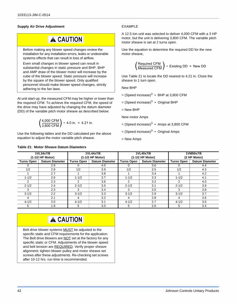
1033113-JIM-C-0514
42 Johnson Controls Unitary Products
Supply Air Drive Adjustment
At unit start-up, the measured CFM may be higher or lower than the required CFM. To achieve the required CFM, the speed of the drive may have adjusted by changing the datum diameter (DD) of the variable pitch motor sheave as described below:
Use the following tables and the DD calculated per the above equation to adjust the motor variable pitch sheave.
EXAMPLE
A 12.5 ton unit was selected to deliver 4,000 CFM with a 3 HP motor, but the unit is delivering 3,800 CFM. The variable pitch motor sheave is set at 2 turns open.
Use the equation to determine the required DD for the new motor sheave,
Use Table 21 to locate the DD nearest to 4.21 in. Close the sheave to 1 turn open.
New BHP
= (Speed increase)3 • BHP at 3,800 CFM
= (Speed increase)3 • Original BHP
= New BHP
New motor Amps
= (Speed increase)3 • Amps at 3,800 CFM
= (Speed increase)3 • Original Amps
= New Amps
Before making any blower speed changes review the installation for any installation errors, leaks or undesirable systems effects that can result in loss of airflow.
Even small changes in blower speed can result in substantial changes in static pressure and BHP. BHP and AMP draw of the blower motor will increase by the cube of the blower speed. Static pressure will increase by the square of the blower speed. Only qualified personnel should make blower speed changes, strictly adhering to the fan laws.
Table 21: Motor Sheave Datum Diameters
1VL34x7/8(1-1/2 HP Motor)
1VL44x7/8(1-1/2 HP Motor)
1VL40x7/8(1-1/2 HP Motor)
1VM50x7/8(2 HP Motor)
Turns Open Datum Diameter Turns Open Datum Diameter Turns Open Datum Diameter Turns Open Datum Diameter0 2.9 0 4.0 0 3.6 0 4.4
1/2 2.8 1/2 3.9 1/2 3.5 1/2 4.31 2.7 1 3.8 1 3.4 1 4.2
1-1/2 2.6 1-1/2 3.7 1-1/2 3.3 1-1/2 4.12 2.3 2 3.6 2 3.2 2 4.0
2-1/2 2.4 2-1/2 3.5 2-1/2 3.1 2-1/2 3.93 2.3 3 3.4 3 3.0 3 3.8
3-1/2 2.2 3-1/2 3.3 3-1/2 2.9 3-1/2 3.74 2.1 4 3.2 4 2.8 4 3.6
4-1/2 2.0 4-1/2 3.1 4-1/2 2.7 4-1/2 3.55 1.9 5 3.0 5 2.6 5 3.4
Belt drive blower systems MUST be adjusted to the specific static and CFM requirements for the application. The Belt drive blowers are NOT set at the factory for any specific static or CFM. Adjustments of the blower speed and belt tension are REQUIRED. Verify proper sheave alignment; tighten blower pulley and motor sheave set screws after these adjustments. Re-checking set screws after 10-12 hrs. run time is recommended.

1033113-JIM-C-0514
Johnson Controls Unitary Products 43
Table 22: Additional Static Resistance
Size(Tons)
Model CFM Cooling Only1
1. Add these values to the available static resistance in the respective Blower Performance Tables.
Economizer2 3
2. Deduct these values from the available external static pressure shown in the respective Blower Performance Tables.3. The pressure drop through the economizer is greater for 100% outdoor air than for 100% return air. If the resistance of the return air duct
is less than 0.25 IWG, the unit will deliver less CFM during full economizer operation.
4” Pleated Filter2 Electric Heat kW2
3 6 9 15 20 24
JA3 (3) J**ZT
900 0.05 -0.05 0.01 0.00 0.00 0.00 0.01 0.01 0.01
1000 0.05 -0.03 0.02 0.00 0.00 0.00 0.02 0.02 0.02
1100 0.04 -0.02 0.03 0.01 0.01 0.01 0.02 0.02 0.02
1200 0.04 0.00 0.04 0.01 0.01 0.01 0.02 0.02 0.02
1300 0.03 0.01 0.05 0.01 0.01 0.01 0.03 0.03 0.03
1400 0.03 0.03 0.07 0.02 0.02 0.02 0.03 0.03 0.03
1500 0.03 0.04 0.08 0.02 0.02 0.02 0.04 0.04 0.04
JA4 (4)JA5 (5)
J**ZT
1200 -0.01 0.10 0.05 0.01 0.01 0.01 0.02 0.02 0.02
1300 -0.01 0.11 0.06 0.01 0.01 0.01 0.03 0.03 0.03
1400 -0.01 0.12 0.06 0.02 0.02 0.02 0.03 0.03 0.03
1500 -0.01 0.13 0.07 0.02 0.02 0.02 0.04 0.04 0.04
1600 -0.01 0.14 0.08 0.02 0.02 0.02 0.04 0.04 0.04
1700 -0.01 0.15 0.08 0.03 0.03 0.03 0.05 0.05 0.05
1800 -0.02 0.16 0.09 0.03 0.03 0.03 0.05 0.05 0.05
1900 -0.02 0.17 0.10 0.04 0.04 0.04 0.06 0.06 0.06
2000 -0.02 0.18 0.10 0.04 0.04 0.04 0.07 0.07 0.07
2100 -0.03 0.19 0.11 0.05 0.05 0.05 0.07 0.07 0.07
2200 -0.03 0.20 0.12 0.06 0.06 0.06 0.08 0.08 0.08
2300 -0.04 0.21 0.12 0.06 0.06 0.06 0.09 0.09 0.09
2400 -0.04 0.22 0.13 0.07 0.07 0.07 0.10 0.10 0.10
2500 -0.05 0.23 0.14 0.08 0.08 0.08 0.11 0.11 0.11

1033113-JIM-C-0514
44 Johnson Controls Unitary Products
Operation
Cooling Operation (Intelli-Comfort II)
• With a demand for first stage cooling either from a thermostat or space sensor, the low-voltage control circuit to "C1" and "G" is completed. For first stage cooling, the compressor is energized and the 1st stage operates (67% capacity). The UCB will energize the VFD equipped blower motor at low speed as set in the Intelli-Comfort II control. When the thermostat calls for the second stage of cooling, the low-voltage control circuit to "C2" is completed. The control board energizes the 2nd stage of the compressor (100% capacity). If there is an initial call for both stages of cooling, the UCB will delay energizing the 2nd stage of the compressor by 30 seconds in order to avoid a power rush. Once the thermostat has been satisfied, it will de-energize C1 and C2. If the compressor has satisfied the minimum run time (3 min default), the compressors and condenser fans are de-energized. Otherwise, the unit operates until the minimum run has been completed. Upon the compressor de-energizing, the blower is stopped following the elapse of the fan off delay for cooling.
• To be available, a compressor must not be locked-out due to a high or low-pressure switch or freezestat trip and the Anti- Short Cycle Delay (5 min default) must have elapsed.
Free Cooling Operation with Economizer (Intelli-Comfort II)
• With a demand for first stage cooling either from a thermostat or space sensor and the outside air is suitable for free cooling, the dampers will be modulated to maintain supply air temperature to within +/- 1 degree of the Free Cooling SAT Upper Setpoint. If the output to the economizer actuator is at 10 vdc and the supply air temperature cannot be controlled to within 5 degrees of the Free Cooling SAT Upper Setpoint, one compressor will be energized. The economizer will then be modulated to maintain supply air temperature to within +/- 1 degree of the Free Cooling SAT Upper Setpoint.
• If a demand for second stage cooling occurs and the economizer is already modulating to maintain the supply air temperature to the Cooling SAT Upper Setpoint, the setpoint will be changed to the Free Cooling SAT Lower Setpoint. Any compressors that are energized will remain energized and the economizer dampers will be modulated to maintain supply air temperature to within +/- 1 degree of the Cooling SAT Lower Setpoint. If the output to the economizer actuator is at 10 vdc and the supply air temperature cannot be controlled to within 5 degrees of the Cooling SAT Lower Setpoint, compressor stage 2 will be energized. The economizer will then be modulated to maintain supply air temperature to within +/- 1 degree of the Cooling SAT Lower Setpoint.
• If the output to the economizer actuator is at minimum position and the supply air temperature drops more than 5 degrees below the current economizer SAT setpoint, the highest stage compressor will be de-energized as long as the minimum run time has elapsed.
Economizer With Single Enthalpy Sensor
When the room thermostat calls for cooling, the low voltage control circuit from “R” to “G” and “Y1” is completed. The UCB energizes the blower motor (if the fan switch on the room thermostat is set in the “AUTO” position) and drives the economizer dampers from fully closed to their minimum position. If the enthalpy of the outdoor air is below the setpoint of the enthalpy controller (previously determined), “Y1” energizes the economizer. The dampers will modulate to maintain a constant supply air temperature as monitored by the discharge air sensor. If the outdoor air enthalpy is above the setpoint, “Y1” energizes the compressor and condenser fan motor only.
Once the thermostat has been satisfied, it will de-energize “Y1”. If the compressor has satisfied its minimum run time, the compressor and condenser fan are de-energized. Otherwise, the unit operates the cooling system until the minimum run times for the compressor has been completed. After the compressor de-energizes, the blower is stopped following the elapse of the fan off delay for cooling, and the economizer damper goes to the closed position. If the unit is in continues fan operation the economizer damper goes to the min. position.
Economizer With Dual Enthalpy Sensors
The operation with the dual enthalpy sensors is identical to the single sensor except that a second enthalpy sensor is mounted in the return air. This return air sensor allows the economizer to choose between outdoor air and return air, whichever has the lowest enthalpy value, to provide maximum operating efficiency.
Economizer With Power Exhaust
A unit equipped with an economizer (single or dual enthalpy) and a power exhaust operates as specified above with one addition. The power exhaust motor is energized 45 seconds after the actuator position exceeds the exhaust fan set point on the economizer control. As always, the "R" to "G" connection provides minimum position but does not provide power exhaust operation.
Motorized Outdoor Air Dampers
This system operation is the same as the units with no outdoor air options with one exception. When the "R" to "G" circuit is complete, the motorized damper drives open to a position set by the thumbwheel on the damper motor. When the "R" to "G" circuit is opened, the damper spring returns fully closed.
Cooling Operation Errors
Each cooling system is monitored for operation outside of the intended parameters. Errors are handled as described below. All system errors override minimum run times for compressors.

1033113-JIM-C-0514
Johnson Controls Unitary Products 45
High-Pressure Limit Switch
During cooling operation, if a high-pressure limit switch opens, the UCB will de-energize the associated compressor, initiate the ASCD (Anti-short cycle delay), and, if the other compressor is idle, stop the condenser fans. If the call for cooling is still present at the conclusion of the ASCD, the UCB will re-energize the halted compressor.
Should a high-pressure switch open three times within two hours of operation, the UCB will lock-out the associated compressor and flash a code (see Table 28). If the other compressor is inactive, the condenser fans will be de-energized.
Low-Pressure Limit Switch
The low-pressure limit switch is not monitored during the initial 30 seconds of a cooling system's operation. For the following 30 seconds, the UCB will monitor the low-pressure switch to ensure it closes. If the low-pressure switch fails to close after the 30-second monitoring phase, the UCB will de-energize the associated compressor, initiate the ASCD, and, if the other compressor is idle, stop the condenser fans.
Once the low-pressure switch has been proven (closed during the 30-second monitor period described above), the UCB will monitor the low-pressure limit switch for any openings. If the low-pressure switch opens for greater than 5 seconds, the UCB will de-energize the associated compressor, initiate the ASCD, and, if the other compressor is idle, stop the condenser fans.
If the call for cooling is still present at the conclusion of the ASCD, the UCB will re-energize the halted compressor.
Should a low-pressure switch open three times within one hour of operation, the UCB will lock-out the associated compressor and flash a code (Table 28). If the other compressor is inactive, the condenser fans will be de-energized.
Freezestat
During cooling operation, if a freezestat opens, the UCB will de-energize the associated compressor, initiate the ASCD, and, if the other compressor is idle, stop the condenser fans. If the call for cooling is still present at the conclusion of the ASCD, the UCB will re-energize the halted compressor.
Should a freezestat open three times within two hours of operation, the UCB will lock-out the associated compressor and flash a code (Table 28). If the other compressor is inactive, the condenser fans will be de-energized.
Safety Controls
The unit control board monitors the following inputs for each cooling system:
1. A suction line freezestat to protect against low evaporator temperatures due to a low airflow or a low return air temperature, (opens at 26 ± 5 °F and resets at 38 ± 5°F).
2. A high-pressure switch to protect against excessive discharge pressures due to a blocked condenser coil or a condenser motor failure, (opens at 625 ± 25 psig).
3. A low-pressure switch to protect against loss of refrigerant charge, (opens at 50 ± 5 psig).
The above pressure switches are hard-soldered to the unit. The refrigeration systems are independently monitored and controlled. On any fault, only the associated system will be affected by any safety/preventive action. The other refrigerant system will continue in operation unless it is affected by the fault as well.
The unit control board monitors the temperature limit switch of electric heat units and the temperature limit switch and the gas valve of gas furnace units.
Compressor Protection
In addition to the external pressure switches, the compressors also have inherent (internal) protection. If there is an abnormal temperature rise in a compressor, the protector will open to shut down the compressor. The UCB incorporates features to minimize compressor wear and damage. An Anti-Short Cycle Delay (ASCD) is utilized to prevent operation of a compressor too soon after its previous run. Additionally, a minimum run time is imposed any time a compressor is energized.
The ASCD is initiated on unit start-up and on any compressor reset or lock-out.
Flash Codes
The UCB will initiate a flash code associated with errors within the system. Refer to UNIT CONTROL BOARD FLASH CODES Table 28.
Reset
Remove the call for cooling, by raising thermostat setting higher than the conditioned space temperature. This resets any pressure or freezestat flash codes.
Electric Heating Sequence Of Operations
The following sequence describes the operation of the electric heat section.
Two-stage heating:
a. Upon a call for first stage heat by the thermostat, the heater relay (RA) will be energized. After completing the specified fan on delay for heating, the UCB will energize the blower motor. If the second stage of heat is required, heater relay (RB) will be energized. After completing the specified fan on delay for heating, the UCB will energize the blower motor.
b The thermostat will cycle the electric heat to satisfy the heating requirements of the conditioned space.

1033113-JIM-C-0514
46 Johnson Controls Unitary Products
Electric Heat Operation Errors
Temperature Limit
If the UCB senses zero volts from the high temperature limit, the indoor blower motor is immediately energized.
This limit is monitored regardless of unit operation status, i.e. the limit is monitored at all times.
If the temperature limit opens three times within one hour, it will lock-on the indoor blower motor and a flash code is initiated (See Table 28).
Safety Controls
The UCB monitors the temperature limit switch of electric heat units.
The control circuit includes the following safety controls:
Limit Switch (Ls)
This control is located inside the heater compartment and is set to open at the temperature indicated in the Electric Heat Limit Setting Tables 23. It resets automatically. The limit switch operates when a high temperature condition, caused by inadequate supply air flow occurs, thus shutting down the heater and energizing the blower.
Flash Codes
The UCB will initiate a flash code associated with errors within the system. Refer to UNIT CONTROL BOARD FLASH CODES Table 28.
Reset
Remove the call for heating by lowering the thermostat setting lower than the conditioned space temperature.This resets any flash codes.
Electric Heat Anticipator Setpoints
It is important that the anticipator setpoint be correct. Too high of a setting will result in longer heat cycles and a greater temperature swing in the conditioned space. Reducing the value below the correct setpoint will give shorter “ON” cycles and may result in the lowering of the temperature within the
Table 23: Electric Heat Limit Setting
UNIT (TONS) VOLTAGEHEATER
kW
LIMIT SWITCH
OPENS °F
JA3ZT (3) 208/230
3 1556 1559 170
15 170
JA4ZT (4) 208/230
6 1559 170
15 17020 170
JA5ZT (5) 208/230
6 1559 170
15 17020 17024 170
JA3ZT (3) 480
3 1556 1559 170
15 170
JA4ZT (4) 480
6 1559 170
15 17020 170
JA5ZT (5) 480
6 1559 170
15 17020 17024 170
JA3ZT (3) 6009 170
15 170
JA4ZT (4) 6009 170
15 17020 170
JA5ZT (5) 600
9 17015 17020 17024 170

1033113-JIM-C-0514
Johnson Controls Unitary Products 47
conditioned space. Refer to Table 24 for the required electric heat anticipator setting.
Gas Heating Sequence Of Operations
When the thermostat calls for the first stage of heating, the low-voltage control circuit from “R” to “W1” is completed. A call for heat passes through the UCB to the Ignition Control Board (ICB). The UCB monitors the “W1” call and acts upon any call for heat by monitoring the Gas Valve (GV). Once voltage has been sensed at the GV, the UCB will initiate the fan on delay for heating, energizing the indoor blower the specified delay has elapsed.
When the thermostat has been satisfied, heating calls are ceased. The GV is immediately closed. The blower is de-energized after the fan off delay for heating has elapsed. The draft motor performs a 30-second post purge.
Ignition Control Board
First Stage Of Heating
When the ICB receives a call for first stage of heating, “W1,” the draft motor is energized. Once the draft motor has been proven, a 30-second purge is initiated. At the end of the purge, the GV is opened, and the spark ignitor is energized for 10 seconds. The ICB then checks for the presence of flame. If flame is detected, the ICB enters a flame stabilization period. If flame was not detected, the GV closes, and a retry operation begins.
During the flame stabilization period, a loss of the flame for 2 seconds will cause the GV to close and the retry operation to begin. After the flame stabilization period, a loss of flame for 3/4 second will cause the GV to close and the retry operation to begin.
At the conclusion of the flame stabilization period, the ICB will operate the gas heat in high fire for an additional 60 seconds (for a total for 120 seconds of high fire operation). After this 60 seconds, the ICB will then use the call for the second stage of heat to control second stage operation of the GV.
When “W1” is satisfied, both valves are closed.
Second Stage Of Heating
When the ICB receives a call for the second stage of heating, “W2,” the ICB conducts a complete first stage ignition sequence. If this sequence is satisfied, the second main valve of the GV is opened.
When “W2” is satisfied, the second main valve is closed.
Retry Operation
When a flame is lost or is not detected during an attempt to achieve ignition, a retry operation occurs. A 30-second purge is performed between ignition attempts.
If the unit fails after three ignition attempts, the furnace is locked-out for one hour. The furnace is monitored during this one-hour period for unsafe conditions.
Recycle Operation
When a flame is lost after the flame stabilization period, a recy-cle operation occurs. If the unit fails after five recycle attempts, the furnace is locked-out for one hour.
Gas Heating Operation Errors
Lock-Out
A one-hour lockout occurs following three retries or five recycles. During the one-hour lockout, flame detection, limit conditions, and main valves are tested. Any improper results will cause the appropriate action to occur. Recycling the low voltage power cancels the lock-out.
Temperature Limit
If the UCB senses zero volts from the high temperature limit, the indoor blower motor is immediately energized. When the UCB again senses 24 volts from the temperature limit, the draft motor will perform a 15-second post-purge and the indoor blower will be de-energized following the elapse of the fan off delay for heating.
This limit is monitored regardless of unit operation status, i.e. this limit is monitored at all times.
If the temperature limit opens three times within one hour, it will lock-on the indoor blower motor and flash code is initiated (See Table 28).
Flame Sense
Flame sensing occurs at all times. If “W1” is not present and a flame is sensed for 2 seconds, the draft motor is energized and the GV is kept off. The ICB halts any operation until a flame is not detected. Once the flame detection is lost, the ICB performs a post-purge. Normal operation is allowed concurrently with the purge (i.e. this purge can be considered the purge associated with a call for “W1”).
If “W1” is present, a flame is sensed, but the GV is not energized, the draft motor is energized until the flame detection is lost. Normal operation is now allowed.
The flame detection circuitry continually tests itself. If the ICB finds the flame detection circuitry to be faulty, the ICB will not permit an ignition sequence and the draft motor is energized. If this failure should occur during an ignition cycle the failure is counted as a recycle.
Table 24: Electric Heat Anticipator Setpoints
SETTING, AMPS
W1 W2
0.13 0.1

1033113-JIM-C-0514
48 Johnson Controls Unitary Products
Gas Valve
The UCB and ICB continuously monitor the GV.
If the ICB senses voltage at the GV when not requested, the ICB will energize the draft motor. The ICB will not operate the furnace until voltage is no longer sensed at the GV. The draft motor is stopped when voltage is not sensed at the GV.
Any time the UCB senses voltage at the GV without a call for heat for a continuous five-minute period, the UCB will lock-on the indoor blower and a flash code is initiated (Table 29). When voltage is no longer sensed at the GV, the UCB will de-energize the indoor blower following the elapse of the fan off delay for heating.
If voltage has been sensed at the GV for at least 15 seconds during the fan on delay for heating and GV voltage or “W1” is lost, the indoor blower is forced on for the length of the fan off delay for heating.
During a call for heat, if the UCB does not sense voltage at the GV for a continuous five-minute period the UCB will initiate a flash code (Table 28). The indoor blower motor will not be locked-on while there is no GV voltage.
Safety Controls
The UCB monitors the temperature limit switch of gas heat units.
The control circuit includes the following safety controls:
Limit Switch (LS)
This control is located inside the gas heat compartment and is set to open at the temperature indicated in Table 9. It resets automatically. The limit switch operates when a high temperature condition, caused by inadequate supply air flow occurs, thus shutting down the heater and energizing the blower.
Auxiliary Limit Switch (ALS)
This control is located inside the supply air compartment and is set to open at the temperature indicated in Table 9. It resets manually. The limit switch operates when a high temperature condition, caused by inadequate supply air flow occurs, thus shutting down the heater and energizing the blower.
The auxiliary limit switch is wired in series with the limit switch. As such, the UCB cannot distinguish the auxiliary limit and the gas heat limit switch operation except the auxiliary is manual reset. Consequently, the control will respond in the same manner as outlined above under “Limit Switch”.
The ICB monitors the Pressure and Rollout switches of gas heat units.
The control circuit includes the following safety controls:
Pressure Switch (PS)
Once the draft motor has reached full speed and closes the pressure switch during a normal ignition sequence, if the pressure sw opens for 2 seconds, the GV will be de-energized, the ignition cycle is aborted, and the ICB flashes the appropriate code. See Table 29 Ignition Control Flash Codes. The draft motor is energized until the pressure switch closes or “W1” is lost.
Rollout Switch (ROS)
The rollout switch is wired in series with the pressure switch. As such, the ICB cannot distinguish the rollout switch operation from that of the pressure switch.
Consequently, the control will only respond in the same manner as outlined above under “Pressure Switch”. An open rollout will inhibit the gas valve from actuating.
Internal Microprocessor Failure
If the ICB detects an internal failure, it will cease all outputs, ignore inputs, and display the proper flash code for control replacement. The ICB remains in this condition until replaced.
Flash Codes
The ICB will initiate a flash code associated with errors within the system. Refer to IGNITION CONTROL FLASH CODES Table 29.
Resets
Remove the call for heating by lowering the thermostat setting lower than the conditioned space temperature. This resets any flash codes.
Gas Heat Anticipator Setpoints
It is important that the anticipator setpoint be correct. Too high of a setting will result in longer heat cycles and a greater temperature swing in the conditioned space. Reducing the value below the correct setpoint will give shorter “ON cycles and may result in the lowering of the temperature within the conditioned space. Refer to Table 25 for the required gas heat anticipator setting.
Start-Up (Cooling)
Prestart Check List
After installation has been completed:
1. Check the electrical supply voltage being supplied. Be sure that it is the same as listed on the unit nameplate.
Table 25: Gas Heat Anticipator Setpoints
SETTING, AMPS
W1 W2
0.65 0.1

1033113-JIM-C-0514
Johnson Controls Unitary Products 49
2. Set the room thermostat to the off position.
3. Turn unit electrical power on.
4. Set the room thermostat fan switch to on.
5. Check indoor blower rotation.
• If blower rotation is in the wrong direction. Refer to Phasing Section in general information section.
Check blower drive belt tension.
6. Check the unit supply air (CFM).
7. Measure evaporator fan motor's amp draw.
8. Set the room thermostat fan switch to off.
9. Turn unit electrical power off.
Operating Instructions
1. Turn unit electrical power on.
NOTE: Prior to each cooling season, the crankcase heaters must be energized at least 10 hours before the system is put into operation.
2. Set the room thermostat setting to lower than the room temperature.
3. First stage compressors will energize after the built-in time delay (five minutes).
4. The second stage of the thermostat will energize second stage compressor if needed.
Post Start Check List
1. Verify proper system pressures for both circuits.
2. Measure the temperature drop across the evaporator coil.
Start-Up (Gas Heat)
Pre-Start Check List
Complete the following checks before starting the unit.
1. Check the type of gas being supplied. Be sure that it is the same as listed on the unit nameplate.
2. Make sure that the vent outlet and combustion air inlet are free of any debris or obstruction.
Operating Instructions
Lighting The Main Burners
1. Turn “OFF” electric power to unit.
2. Turn room thermostat to lowest setting.
3. Turn gas valve counter-clockwise to “ON” position (See Figure 30).
4. Turn “ON” electric power to unit.
5. If thermostat set temperature is above room temperature, the main burners will ignite. If a second stage of heat is called for, the main burners for second stage heat will ignite for the second stage heat.
Post Start Checklist
After the entire control circuit has been energized and the heating section is operating, make the following checks:
1. Check for gas leaks in the unit piping as well as the supply piping.
2. Check for correct manifold gas pressures. (See CHECKING GAS INPUT.)
3. Check the supply gas pressure. It must be within the limits shown on the rating nameplate. Supply pressure should be checked with all gas appliances in the building at full fire. At no time should the standby gas pressure exceed 10.5 in. or the operating pressure drop below 4.5 in for natural gas units. If gas pressure is outside these limits, contact the local gas utility or propane supplier for corrective action.
Shut Down
1. Set the thermostat to the lowest temperature setting.
2. Turn “OFF” all electric power to unit.
3. Open gas heat access panel.
4. Turn gas valve clockwise to “OFF” position (See Figure 30).
Checking Gas Heat Input
This unit has two stages of gas heat. The first stage is 70% of the full fire input and is considered the minimum input for the furnace. The intended input for each furnace is shown in Table 27. The table applies to units operating on 60 Hz power only.
To determine the rate of gas flow (Second Stage).
1. Turn off all other gas appliances connected to the gas meter.
2. Turn on the furnace and make sure the thermostat is calling for Second stage (100% input) heat.
This furnace is equipped with an automatic re-ignition system. DO NOT attempt to manually light the pilot.
FIRE OR EXPLOSION HAZARD
Failure to follow the safety warning exactly could result in serious injury, death or property damage.
Never test for gas leaks with an open flame. use a commercially available soap solution made specifically for the detection of leaks to check all connections. A fire or explosion may result causing property damage, personal injury or loss of life.

1033113-JIM-C-0514
50 Johnson Controls Unitary Products
3. Measure the time needed for one revolution of the hand on the smallest dial on the meter. A typical gas meter has a 1/2 or a 1 cubic foot test dial.
4. Using the number of seconds it takes for one revolution of the dial, calculate the cubic feet of gas consumed per hour. (See example below).
5. If necessary, adjust the high pressure regulator as discussed in the section “Manifold Gas Pressure Adjustment”. Be sure not to over-fire the furnace on Second stage. If in doubt, it is better to leave the Second stage of the furnace slightly under-fired. Repeat Steps 1-5.
To determine the rate of gas flow (First Stage)
1. Turn off all other gas appliances connected to the gas meter.
2. Turn on the furnace and make sure the thermostat is calling for first stage (70% input) heat.
3. Even when the thermostat is calling for first stage heat, the unit will light on second stage and will run on Second stage for 1 minute. Allow this one-minute time period to expire and be certain the unit is running on first stage.
4. Measure the time needed for one revolution of the hand on the smallest dial on the meter. A typical gas meter has a 1/2 or a 1 cubic foot test dial.
5. Using the number of seconds it takes for one revolution of the dial, calculate the cubic feet of gas consumed per hour (See example below).
6. If necessary, adjust the low pressure regulator as discussed in the section “Manifold Gas Pressure Adjustment”. Be sure not to under-fire the furnace on first stage. If in doubt, it is better to leave the first stage of the furnace slightly over-fired (greater than 70% input). Repeat Steps 1-6.
NOTE: To find the Btu input, multiply the number of cubic feet of gas consumed per hour by the Btu content of the gas in your particular locality (contact your gas company for this information as it varies widely from area to area).
EXAMPLE
By actual measurement, it takes 19 seconds for the hand on a 1 cubic foot dial to make a revolution with a 192,000 Btuh furnace running. To determine rotations per minute, divide 60 by 19 = 3.16. To calculate rotations per hour, multiply 3.16 60 = 189.6. Multiply 189.6 1 (0.5 if using a 1/2 cubic foot dial) = 189.6. Multiply 189.6 (the Btu rating of the gas). For this example, assume the gas has a Btu rating of 1050 Btu/ft.3. The result of 199,000 Btuh is within 5% of the 192,000 Btuh rating of the furnace.
Manifold Gas Pressure Adjustment
This gas furnace has two heat stages. Therefore, the gas valve has two adjustment screws located under a plastic protective cover. The second stage (100% input) adjustment screw is adjacent to the “HI” marking on the valve and the first stage (60% input) adjustment screw is located adjacent to the “LO” marking on the valve (See Figure 30).
Manifold pressure adjustment procedure.
Adjust second stage (100% input) pressure first, then adjust first stage (70% input) pressure.
Table 26: Gas Rate Cubic Feet Per Hour
Seconds forOne Rev.
Size of Test Dial1/2 cu. ft. 1 cu. ft.
10 180 36012 150 30014 129 25716 113 22518 100 20020 90 18022 82 16424 75 15026 69 13828 64 12930 60 12032 56 11334 53 10636 50 10038 47 9540 45 9042 43 8644 41 8246 39 7848 37 7550 36 7252 35 6954 34 6756 32 6458 31 6260 30 60

1033113-JIM-C-0514
Johnson Controls Unitary Products 51
1. Turn off all power to the unit.
2. Using the outlet pressure port on the gas valve, connect a manometer to monitor the manifold pressure.
3. Remove plastic cap covering HI and LO pressure adjustment screws.
4. Turn on power to the unit.
5. Set thermostat to call for second stage heat and start furnace.
6. If necessary, using a screwdriver, turn the second stage adjustment screw (adjacent to the “HI” marking on the valve) clockwise to increase manifold pressure or counterclockwise to decrease manifold pressure. Be sure not to over-fire the unit on second stage.
7. After the high manifold pressure has been checked, adjust the thermostat to call for first stage heat.
8. If necessary, using a screwdriver, turn the first stage adjustment screw (adjacent to the “LO” marking on the valve) clockwise to increase manifold pressure or counterclockwise to decrease manifold pressure. Be sure not to under-fire the unit on first stage.
9. Once pressure has been checked, replace the plastic cap covering the HI and LO pressure adjustment screws.
NOTE: When using natural gas, the manifold pressure for second stage (100% input) should be 3.5 IWG ± 0.3.
The manifold pressure for first stage (60% input) when using natural gas should be 1.5 IWG ± 0.3.
Table 27: Gas Heat Stages
Unit# of Burner
Tubes1st Stage
Input (Mbh)
2nd Stage Input(Mbh)
Total Input (Mbh)
Size Opt.
JA3
A05 4 60 - 60A07 4 80 - 80A09 6 120 - 120N05 4 45 15 60N07 4 56 24 80N09 6 84 36 120
JA4
A05 4 60 - 60A07 4 80 - 80A09 6 120 - 120N05 4 45 15 60N07 4 56 24 80N09 6 84 36 120
JA5
A07 4 80 - 80A09 6 120 - 120A13 8 160 - 160N07 4 56 24 80N09 6 84 36 120N13 8 112 48 160

1033113-JIM-C-0514
52 Johnson Controls Unitary Products
Adjustment Of Temperature Rise
The temperature rise (the difference of temperature between the return air and the heated air from the furnace) must lie within the range shown on the CSA rating plate and the data in Table 9.
After the temperature rise has been determined, the CFM can be calculated as follows:
After about 20 minutes of operation, determine the furnace temperature rise. Take readings of both the return air and the heated air in the ducts (about 6 feet from the furnace) where they will not be affected by radiant heat. Increase the blower CFM to decrease the temperature rise; decrease the blower CFM to increase the rise (See SUPPLY AIR DRIVE ADJUSTMENT).
NOTE: Each gas heat exchanger size has a minimum allowable CFM. Below this CFM, the limit will open.
Burners/Orifices Inspection/Servicing
Before checking or changing burners, pilot or orifices, CLOSE MAIN MANUAL SHUT-OFF VALVE AND SHUT OFF ALL POWER TO THE UNIT.
1. Open the union fitting just upstream of the unit gas valve and downstream from the main manual shut-off valve in the gas supply line.
2. Remove the screws holding each end of the manifold to the manifold supports.
3. Disconnect wiring to the gas valves and spark igniter(s). Remove the manifold & gas valve assembly. Orifices can now be inspected and/or replaced.
To service burners, complete step 4.
4. Remove the heat shield on top of the manifold supports. Burners are now accessible for inspection and/or replacement.
NOTE: Reverse the above procedure to replace the assemblies.
Make sure that burners are level and seat at the rear of the gas orifice.
Figure 29: Typical Flame
Figure 30: Typical Two Stage Gas Valve
Figure 31: Typical Single Stage Gas Valve
HEAT EXCHANGER TUBE
BURNER FLAME(BLUE ONLY)
IGNITORBURNER BRACKET
BURNER
GASSUPPLY
PIPE
INLETPRESSURE
TAP
HIGH & LOW GAS ADJUSTMENT
OUTLETPRESSURE
TAP
MATE-N-LOCKCONNECTORS
HILO
ON
OFF
MV
C
HI
INLETPRESSURE
TAP
OUTLET PRESSURE
TAP
GASADJUSTMENT
ELECTRICAL TERMINALS

1033113-JIM-C-0514
Johnson Controls Unitary Products 53
Troubleshooting
On calls for cooling, if the compressors are operating but the supply air blower motor does not energize after a short delay (the room thermostat fan switch is in the “AUTO” position).
1. Turn the thermostat fan switch to the ON position. If the supply air blower motor does not energize, go to Step 3.
2. If the blower motor runs with the fan switch in the ON position but will not run after the compressor has energized when the fan switch is in the AUTO position, check the room thermostat for contact between R and G in the AUTO position during calls for cooling.
3. If the supply air blower motor does not energize when the fan switch is set to ON, check that line voltage is being supplied to the contacts of the M3, contactor, and that the contactor is pulled in. Check for loose wiring between the contactor and the supply air blower motor.
4. If M3 is pulled in and voltage is supplied to M3, lightly touch the supply air blower motor housing. If it is hot, the motor may be off on internal protection. Cancel any thermostat calls and set the fan switch to AUTO. Wait for the internal overload to reset. Test again when cool.
5. If M3 is not pulled in, check for 24 volts at the M3 coil. If 24 volts are present at M3 but M3 is not pulled in, replace the contactor.
6. Failing the above, if there is line voltage supplied at M3, M3 is pulled in, and the supply air blower motor still does not operate, replace the motor.
7. If 24 volts is not present at M3, check that 24 volts is present at the UCB supply air blower motor terminal, “FAN”. If 24 volts is present at the FAN, check for loose wiring between the UCB and M3.
8. If 24 volts is not present at the “FAN” terminal, check for 24 volts from the room thermostat. If 24 volts are not present from the room thermostat, check for the following:
a. Proper operation of the room thermostat (contact between R and G with the fan switch in the ON position and in the AUTO position during operation calls).
b. Proper wiring between the room thermostat and the UCB.
c. Loose wiring from the room thermostat to the UCB.
9. If 24 volts is present at the room thermostat but not at the UCB, check for proper wiring between the thermostat and the UCB, i.e. that the thermostat G terminal is connected to the G terminal of the UCB, and for loose wiring.
10. If the thermostat and UCB are properly wired, replace the UCB.
On a call for cooling, the supply air blower motor is operating but the compressor is not (the room thermostat fan switch is in the “AUTO” position).
1. If installed, check the position of the economizer blades. If the blades are open, the economizer is providing free cooling and the compressors will not immediately operate. If both stages of cooling are requested simultaneously and the economizer provides free cooling, following a short delay the compressor will be energized unless it is locked out, unless this option has been disabled through computer communications.
2. If no economizer is installed or the economizer is not opening to provide free cooling and the compressor does not energize on a call for cooling, check for line voltage at the compressor contactor, M1, and that the contactor is pulled in. Check for loose wiring between the contactor and the compressor.
3. If M1 is pulled in and voltage is supplied at M1, lightly touch the compressor housing. If it is hot, the compressor may be off on inherent protection. Cancel any calls for cooling and wait for the internal overload to reset. Test again when cool.
4. If M1 is not pulled in, check for 24 volts at the M1 coil. If 24 volts are present and M1 is not pulled in, replace the contactor.
5. Failing the above, if voltage is supplied at M1, M1 is pulled in, and the compressor still does not operate, replace the compressor.
6. If 24 volts is not present at M1, check for 24 volts at the UCB terminal, C1. If 24 volts is present, check for loose wiring between C1 and the compressor contactor.
7. If 24 volts is not present at the C1 terminal, check for 24 volts from the room thermostat at the UCB Y1 terminal. If 24 volts is not present from the room thermostat, check for the following:
a. 24 volts at the thermostat Y1 terminal
b. Proper wiring between the room thermostat and the UCB, i.e. Y1 to Y1, Y2 to Y2
c. Loose wiring from the room thermostat to the UCB.
Troubleshooting of components may require opening the electrical control box with the power connected to the unit. Use extreme care when working with live circuits! Check the unit nameplate for the correct line voltage and set the voltmeter to the correct range before making any connections with line terminals.
When not necessary, shut off all electric power to the unit prior to any of the following maintenance procedures so as to prevent personal injury.
Label all wires prior to disconnection when servicing controls. Wiring errors can cause improper and dangerous operation which could cause injury to person and/or damage unit components. Verify proper operation after servicing.

1033113-JIM-C-0514
54 Johnson Controls Unitary Products
8. If 24 volts is present at the UCB Y1 terminal, the compressor may be out due to an open high-pressure switch, low-pressure switch, or freezestat. Check for 24 volts at the HPS1, LPS1, and FS1 terminals of the UCB. If a switch has opened, there should be a voltage potential between the UCB terminals, e.g. if LPS1 has opened, there will be a 24-volt potential between the LPS1 terminals.
9. If 24 volts is present at the UCB Y1 terminal and none of the protection switches have opened, the UCB may have locked out the compressor for repeat trips. The UCB should be flashing an alarm code. If not, press and release the ALARMS button on the UCB. The UCB will flash the last five alarms on the LED. If the compressor is locked out, cancel any call for cooling. This will reset any compressor lock outs.
NOTE: While the above step will reset any lockouts, the compressor may be held off for the ASCD. See the next step.
10. If 24 volts is present at the UCB Y1 terminal and none of the switches are open and the compressor is not locked out, the UCB may have the compressor in an ASCD. Check the LED for an indication of an ASCD cycle. The ASCD should time out within 5 minutes. Press and release the TEST button to reset all ASCDs.
11. If 24 volts is present at the UCB Y1 terminal and the compressor is not out due to a protective switch trip, repeat trip lock out, or ASCD, the economizer terminals of the UCB may be improperly wired. Check for 24 volts at the Y1 “OUT” terminal of the UCB. If 24 volts is present, trace the wiring from Y1 “OUT” for incorrect wiring. If 24 volts is not present at the Y1 “OUT” terminal, the UCB must be replaced.
12. For units without economizers: If 24 volts is present at the Y1 OUT terminal, check for 24 volts at the Y1 “ECON” terminal. If 24 volts is not present, check for loose wiring from the Y1 “OUT” terminal to the Mate-N-Lock plug, the jumper in the Mate-N-Lock plug, and in the wiring from the Mate-N-Lock plug to the Y1 “ECON” terminal.
13. For units with economizers: If 24 volts is present at the Y1 “OUT” terminal, check for 24 volts at the Y1 “ECON” terminal. If 24 volts is not present, check for loose wiring from the Y1 “OUT” terminal to the Mate-N-Lock plug, a poor connection between the UCB and economizer Mate-N-Lock plugs, loose wiring from the Mate-N-Lock plug to the economizer, back to the Mate-N-Lock plug, and from the Mate-N-Lock plug to the Y1 “ECON” terminal. If nothing is found, the economizer actuator may have faulted and is failing to return the 24-volt “call” to the Y1 “ECON” terminal even though the economizer is not providing free cooling. To test, disconnect the Mate-N-Locks and jumper between
the WHITE and YELLOW wires of the UCB’s Mate-N-Lock plug. If the compressor energizes, there is a fault in the economizer wiring or actuator.
14. The UCB can be programmed to lock out compressor operation during free cooling and in low ambient conditions. These options are not enabled by default. Local distributors can test the UCB for this programming.
For units with factory installed economizers, the UCB is programmed to lock out compressor operation when the LAS set point is reached.
For units without factory installed or with field installed economizers, the UCB allows compressor operation all the time. This programming can be checked or changed by the local distributor.
15. If none of the above correct the error, replace the UCB.
Gas Heat Troubleshooting Guide
Troubleshooting of components may require opening the electrical control box with the power connected to the unit. Use extreme care when working with live circuits! Check the unit nameplate for the correct line voltage and set the voltmeter to the correct range before making any connections with line terminals.
When not necessary, shut off all electric power to the unit prior to any of the following maintenance procedures so as to prevent personal injury.
Label all wires prior to disconnection when servicing controls. Wiring errors can cause improper and dangerous operation, which could cause injury to person and/or damage unit components. Verify proper operation after servicing.
The furnace may shut down on a high temperature condition during the procedure. If this occurs, the UCB energize the supply air blower motor until the high temperature limit has reset. Caution should be used at all times as the supply air blower may energize regardless of the room thermostat fan switch position.

1033113-JIM-C-0514
Johnson Controls Unitary Products 55
On calls for heating, the draft motor operates and the furnace lights but the supply air blower motor does not energize after a short delay (the room thermostat fan switch is in “AUTO” position).
1. Place the thermostat fan switch in the “ON” position. If the supply air blower motor energizes, go to Step 9.
2. If the supply air blower motor does not energize when the fan switch is set to “ON,” check that line voltage is being supplied to the contacts of the M3 contactor, and that the contactor is pulled in. Check for loose wiring between the contactor and the supply air blower motor.
3. If M3 is pulled in and voltage is supplied at M3, lightly touch the supply air blower motor housing. If it is hot, the motor may be off on inherent protection. Cancel any thermostat calls and set the fan switch to “AUTO”, wait for the internal overload to reset. Test again when cool.
4. If M3 is not pulled in, check for 24 volts at the M3 coil. If 24 volts is present at M3 but M3 is not pulled in, replace the contactor.
5. Failing the above, if there is line voltage supplied at M3, M3 is pulled in, and the supply air blower motor still does not operate, replace the motor.
6. If 24 volts is not present at M3, check that 24 volts is present at the supply air blower motor terminal on the UCB. If 24 volts is present at the UCB terminal, check for loose wiring between the UCB and M3.
a. If 24 volts is not present at the UCB supply air blower motor terminal, check for 24 volts from the room thermostat. If 24 volts is not present from the room thermostat, check for the following:
• Proper operation of the room thermostat (contact between R and G with the fan switch in the “ON” position and in the “AUTO” position during operation calls.)
• Proper wiring between the room thermostat and the UCB, and
• Loose wiring from the room thermostat to the UCB
7. If 24 volts is present at the room thermostat but not at the UCB, check for proper wiring between the thermostat and the UCB, i.e. that the thermostat G terminal is connected to the G terminal of the UCB, and for loose wiring.
8. If the thermostat and UCB are properly wired, replace the UCB.
9. If the blower motor runs with the fan switch in the “ON” position but does not run shortly after the furnace has ignited when the fan switch is in the “AUTO” position, check the room thermostat for contact between R and G during “W1” calls.
On calls for heating, the supply air blower operates but the draft motor does not (the room thermostat fan switch is in the “AUTO” position).
1. The draft motor has inherent protection. If the motor shell is hot to the touch, wait for the internal overload to reset.
2. If the motor shell is cold with the room thermostat calling for heat, check for line voltage at the motor leads. If line voltage is present, replace the draft motor.
3. If line voltage is not present, check for line voltage on the ignition control at the “inducer” terminal draft motor relay (DMR or DMC) contacts in the main control box and check to see if the (DMR or DMC) is pulled in.
The draft motor runs but the furnace does not light and the spark igniter does not spark.
1. Check for 24 volts at the spark igniter from the ignition control board (ICB). Check the 24-volt wiring from the ICB to the spark igniter. Check for 24 volts at the ICB spark igniter terminal.
2. Check the ground wiring for the ICB and the gas valve is intact and making good electrical connection. Check the ceramic insulator on the spark igniter for breaks or cracks. Replace the spark igniter if damaged.
3. With the draft motor running, check for 24 volts at the pressure switch terminal on the ICB. If not present, check for 24 volts on the terminal from the pressure switch. If present, go to step 4. If 24 volts is not present, the either pressure or roll out switch is not closed. Or the draft motor is not sufficiently evacuating the heat exchanger tubes or the pressure switch has failed. Check the operation of the pressure switch. Check the line voltage to the unit; if line voltage is low, call the local power company. If the problem persists, the draft motor may need replacement.
4. If the furnace is hot, it may be out on a high temperature limit open; wait for limit reset.
5. If all are intact replace the ICB.
The draft motor runs and the spark igniter sparks at the burner, but the burner does not ignite and a gas odor is not detected at the draft motor outlet.
1. Check to ensure gas is being supplied to the unit. Confirm that the gas pressure to the unit is within the proper limits as described in the “POST START CHECKLIST”.
2. Check the voltage at the gas valve and at the gas valve terminals on the ICB. Check all wiring between the ICB and the gas valve. Check to make sure the ground connections are intact.
3. If 24 volts is present, remove the pilot burner and the orifice. The removal procedure is described in “BURNER/ORIFICE INSPECTION/SERVICING.” Inspect the orifice for obstruction. If it is clear, replace the gas valve.
Main burners light but exhibit erratic flame characteristics.
1. Check the main burner orifices for obstruction and alignment. The removal procedure is described in “BURNER/ORIFICE INSPECTION/SERVICING”. Clean or replace burner orifices and burners as needed.
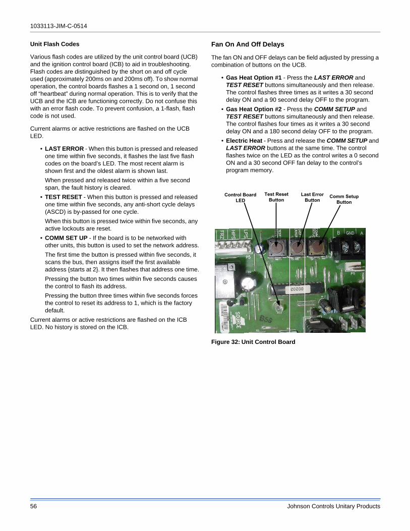
1033113-JIM-C-0514
56 Johnson Controls Unitary Products
Unit Flash Codes
Various flash codes are utilized by the unit control board (UCB) and the ignition control board (ICB) to aid in troubleshooting. Flash codes are distinguished by the short on and off cycle used (approximately 200ms on and 200ms off). To show normal operation, the control boards flashes a 1 second on, 1 second off “heartbeat” during normal operation. This is to verify that the UCB and the ICB are functioning correctly. Do not confuse this with an error flash code. To prevent confusion, a 1-flash, flash code is not used.
Current alarms or active restrictions are flashed on the UCB LED.
• LAST ERROR - When this button is pressed and released one time within five seconds, it flashes the last five flash codes on the board’s LED. The most recent alarm is shown first and the oldest alarm is shown last.
When pressed and released twice within a five second span, the fault history is cleared.
• TEST RESET - When this button is pressed and released one time within five seconds, any anti-short cycle delays (ASCD) is by-passed for one cycle.
When this button is pressed twice within five seconds, any active lockouts are reset.
• COMM SET UP - If the board is to be networked with other units, this button is used to set the network address.
The first time the button is pressed within five seconds, it scans the bus, then assigns itself the first available address {starts at 2}. It then flashes that address one time.
Pressing the button two times within five seconds causes the control to flash its address.
Pressing the button three times within five seconds forces the control to reset its address to 1, which is the factory default.
Current alarms or active restrictions are flashed on the ICB LED. No history is stored on the ICB.
Fan On And Off Delays
The fan ON and OFF delays can be field adjusted by pressing a combination of buttons on the UCB.
• Gas Heat Option #1 - Press the LAST ERROR and TEST RESET buttons simultaneously and then release. The control flashes three times as it writes a 30 second delay ON and a 90 second delay OFF to the program.
• Gas Heat Option #2 - Press the COMM SETUP and TEST RESET buttons simultaneously and then release. The control flashes four times as it writes a 30 second delay ON and a 180 second delay OFF to the program.
• Electric Heat - Press and release the COMM SETUP and LAST ERROR buttons at the same time. The control flashes twice on the LED as the control writes a 0 second ON and a 30 second OFF fan delay to the control’s program memory.
Figure 32: Unit Control Board
Comm Setup
Button
Last Error
Button
Test Reset
ButtonControl Board
LED

1033113-JIM-C-0514
Johnson Controls Unitary Products 57
Table 30: JA3ZT Charging Table
Table 28: Unit Control Board Flash Codes
Flash Code DescriptionOn Steady Control Failure - Replace ControlHeart Beat Normal Operation
1 Flash Not Applicable2 Flashes Control waiting ASCD1
1. These flash codes do not represent alarms.
3 Flashes HPS1 - Compressor Lock out5 Flashes LPS1 - Compressor Lock out7 Flashes FS1 - Compressor Lock out
9 FlashesIgnition Control Locked Out/Ignition Control Failure / Limit Switch Trip / No Jumper Plug in Heat Section
10 FlashesCompressors Locked Out On Low Outdoor Air Temperature1
11 FlashesCompressors Locked Out Because The Economizer Is Using Free Cooling1
13 Flashes Compressor Held Off Due To Low Voltage1
14 Flashes EEPROM Storage Failure (Control Failure)OFF No Power or Control Failure
Table 29: Ignition Control Flash Codes
Flashes Fault Conditions Check
Steady On Control Failure Control
Heartbeat Normal Operation
1 Not Applicable
2Pressure Switch Stuck Closed
Pressure Switch
3Pressure Switch FailedTo Close
Venter Pressure SwitchVent Blocked
4 Limit Switch OpenMain LimitAUX Limit
5
Flame Present With GasOff First Stage Gas ValveEnergized With W1 OffSecond Stage Gas ValveEnergized With First StageGas Valve Off
Gas Valve
6 Ignition Lockout
Gas FlowGas PressureGas ValveFlame Sensor
Steady OffNo Power Or ControlFailure
24VAC or Control
Air FlowIndoor Db/Wb
OutdoorDB
Suction Pressure
Suction Temp.
Liquid Pressure
LiquidTemp.
Delta TDb
CompressorAmps
300 Cfm/Ton80/62
75 134 57 259 77 -25 7.6
85 133 56 302 87 -26 8.1
95 133 54 345 96 -26 8.6
300 Cfm/Ton80/67
75 134 58 258 77 -25 7.6
85 137 57 303 87 -24 8.0
95 139 56 347 97 -23 8.5
300 Cfm/Ton80/72
75 135 60 258 77 -25 7.5
85 140 59 303 87 -23 8.0
95 146 58 348 97 -20 8.4
300 Cfm/Ton75/62
75 128 53 258 77 -23 7.6
85 129 52 301 86 -22 8.1
95 129 52 344 96 -22 8.6
400 Cfm/Ton80/62
75 140 62 261 77 -23 7.9
85 141 61 304 87 -23 8.3
95 143 60 347 97 -22 8.8
400 Cfm/Ton80/67
75 141 63 261 77 -23 7.8
85 144 62 305 87 -22 8.3
95 146 60 349 97 -21 8.8
400 Cfm/Ton80/72
75 143 64 261 77 -22 7.8
85 146 62 306 87 -20 8.3
95 149 60 351 97 -19 8.7
400 Cfm/Ton75/62
75 134 58 259 77 -21 7.8
85 136 57 303 87 -20 8.3
95 138 56 346 96 -19 8.8

1033113-JIM-C-0514
58 Johnson Controls Unitary Products
Table 31: JA4ZT Charging Table
Table 32: JA5ZT Charging Table
Air FlowIndoor Db/Wb
OutdoorDB
Suction Pressure
Suction Temp.
Liquid Pressure
LiquidTemp.
Delta TDb
CompressorAmps
300 Cfm/Ton80/62
75 140 63 262 77 -27 9.8
85 139 60 304 87 -27 10.5
95 138 57 346 97 -28 11.2
300 Cfm/Ton80/67
75 141 62 261 78 -26 9.9
85 143 61 306 87 -25 10.6
95 145 61 351 97 -25 11.3
300 Cfm/Ton80/72
75 142 60 260 79 -26 10.0
85 147 63 308 87 -24 10.7
95 152 66 356 96 -22 11.4
300 Cfm/Ton75/62
75 134 59 261 77 -24 9.8
85 134 57 304 87 -24 10.5
95 135 56 347 96 -24 11.2
400 Cfm/Ton80/62
75 144 66 264 77 -24 10.2
85 146 63 306 87 -24 10.9
95 147 61 349 98 -24 11.6
400 Cfm/Ton80/67
75 147 66 265 77 -23 10.3
85 149 64 308 87 -22 11.0
95 152 62 352 98 -22 11.7
400 Cfm/Ton80/72
75 149 65 265 78 -22 10.4
85 153 65 310 88 -21 11.1
95 156 64 354 98 -20 11.8
400 Cfm/Ton75/62
75 139 62 262 77 -22 10.2
85 141 60 305 87 -21 10.9
95 143 59 349 97 -20 11.6
Air FlowIndoor Db/Wb
OutdoorDB
Suction Pressure
Suction Temp.
Liquid Pressure
LiquidTemp.
Delta TDb
CompressorAmps
300 Cfm/Ton80/62
75 139 60 271 79 -27 10.4
85 137 57 316 88 -27 11.3
95 135 54 361 96 -27 12.2
300 Cfm/Ton80/67
75 139 59 274 79 -27 10.6
85 141 59 320 88 -26 11.5
95 143 59 366 97 -25 12.5
300 Cfm/Ton80/72
75 139 59 277 80 -27 10.7
85 145 62 324 89 -24 11.7
95 151 65 371 97 -22 12.8
300 Cfm/Ton75/62
75 133 56 270 78 -24 10.4
85 133 55 317 87 -24 11.3
95 133 54 363 96 -23 12.2
400 Cfm/Ton80/62
75 143 63 272 79 -24 10.5
85 144 61 318 89 -23 11.4
95 145 59 364 98 -23 12.3
400 Cfm/Ton80/67
75 145 62 275 79 -23 10.7
85 147 61 322 88 -22 11.7
95 149 61 369 97 -21 12.6
400 Cfm/Ton80/72
75 147 61 279 79 -23 10.9
85 150 62 326 88 -21 11.9
95 153 62 374 96 -20 12.9
400 Cfm/Ton75/62
75 138 59 272 79 -21 10.5
85 139 58 319 88 -20 11.4
95 140 57 365 97 -20 12.4

1034350-UCL-A-0313
START-UP & SERVICE DATA INSTRUCTION
START-UP CHECKLIST
Date: _______________________________________________________________________________________________________
Job Name: __________________________________________________________________________________________________
Customer Name: _____________________________________________________________________________________________
Address: ____________________________________________________________________________________________________
City: ______________________________ State: ______________________________ Zip: ________________________________
Evaporator Model Number: _______________________________ Serial Number: __________________________________________
Condenser Model Number: _______________________________ Serial Number: __________________________________________
Qualified Start-up Technician: _________________________________ Signature: _________________________________________
HVAC Contractor: _________________________________________________________ Phone: _____________________________
Address: ____________________________________________________________________________________________________
Contractor’s E-mail Address: ____________________________________________________________________________________
Electrical Contractor: _________________________________________________________ Phone:___________________________
Distributor Name: ___________________________________________________________ Phone: ___________________________
WARRANTY STATEMENT
Johnson Controls/UPG is confident that this equipment will operate to the owner's satisfaction if the proper procedures are followed and checks are made at initial start-up. This confidence is supported by the 30 day dealer protection coverage portion of our standard warranty policy which states that Johnson Controls/UPG will cover parts and labor on new equipment start-up failures that are caused by a defect in factory workmanship or material, for a period of 30 days from installation. Refer to current standard warranty policy and warranty manual found on UPGnet for details.
In the event that communication with Johnson Controls/UPG is required regarding technical and/or warranty concerns, all parties to the discussion should have a copy of the equipment start-up sheet for reference. A copy of the original start-up sheet should be filed with the Technical Services Department.
The packaged unit is available in constant or variable air volume versions with a large variety of custom options and accessories available. Therefore, some variation in the startup procedure will exist depending upon the products capacity, control system, options and accessories installed.
This start-up sheet covers all startup check points common to all package equipment. In addition it covers essential startup check points for a number of common installation options. Depending upon the particular unit being started not all sections of this startup sheet will apply. Complete those sections applicable and use the notes section to record any additional information pertinent to your particular installation.
Warranty claims are to be made through the distributor from whom the equipment was purchased.
EQUIPMENT STARTUP
Simplicity PC is required to complete the start-up. Simplicity
PC software can be downloaded from www.york.com.
A copy of the completed start-up sheet should be kept on file
by the distributor providing the equipment and a copy sent to:
Johnson Controls/UPGTechnical Services Department5005 York DriveNorman, OK 73069
COMMERCIAL SPLIT SYSTEMS
7.5 To 50.0 TON
1033113-JIM-C-0514
Johnson Controls Unitary Products 59
Start-Up Sheet

1033113-JIM-C-0514
60 Johnson Controls Unitary Products
1034349-UCL-A-0313
2 Unitary Products Group
SAFETY WARNINGS
The inspections and recording of data outlined in this procedure are required for start-up of Johnson Controls/UPG's packaged products. Industry recognized safety standards and practices must be observed at all times. General industry knowledge and experience are required to assure technician safety. It is the responsibility of the technician to assess all potential dangers and take all steps warranted to perform the work in a safe manner. By addressing those potential dangers, prior to beginning any work, the technician can perform the work in a safe manner with minimal risk of injury.
NOTE: Read and review this entire document before beginningany of the startup procedures.
DESIGN APPLICATION INFORMATION
This information will be available from the specifying engineer who selected the equipment. If the system is a VAV system the CFM will be the airflow when the remote VAV boxes are in the
full open position and the frequency drive is operating at 60 HZ. Do not proceed with the equipment start-up without the
design CFM information.
Design Supply Air CFM: __________________________ Design Return Air CFM: ______________________________________
Design Outdoor Air CFM At Minimum Position: ________________________________________________________________
Total External Static Pressure: _______________________________________________________________________________
Supply Static Pressure: ____________________________________________________________________________________
Return Static Pressure: _____________________________________________________________________________________
Design Building Static Pressure: _____________________________________________________________________________
Outside Air Dilution: Economizer Position Percentage: ____________________________________ _ CFM: ________________
Supply Gas Pressure After Regulator W/o Heat Active _____________________________________ Inches_________________
ADDITIONAL APPLICATION NOTES FROM SPECIFYING ENGINEER:
Lethal voltages are present during some start-up checks. Extreme caution must be used at all times.
Moving parts may be exposed during some startup checks. Extreme caution must be used at all times.

1033113-JIM-C-0514
Johnson Controls Unitary Products 61
1034349-UCL-A-0313
Unitary Products Group 3
REFERENCE
General Inspection Completed See Notes
Unit inspected for shipping, storage, or rigging damage
Unit installed with proper clearances
Unit installed within slope limitations
Refrigeration system checked for gross leaks (presence of oil)
Terminal screws and wiring connections checked for tightness
Filters installed correctly and clean
Economizer hoods installed in operating position
Condensate drain trapped properly, refer to Installation Manual
Economizer damper linkage tight
Gas Heat vent hood installed
All field wiring (power and control) complete
Air Moving Inspection Completed See Notes
Alignment of drive components
Belt tension adjusted properly
Blower pulleys tight on shaft, bearing set screws tight, wheel tight to shaft
Pressure switch or transducer tubing installed properly
Exhaust Inspection Powered Barometric Relief Completed See Notes
Check hub for tightness
Check fan blade for clearance
Check for proper rotation
Check for proper mounting (screen faces towards unit)
Prove operation by increasing minimum setting on economizer
Economizer Inspection Standard BAS Completed See Notes
CO2 sensor installed Yes No
Check economizer setting A B C D
Prove economizer open/close through PC or Control Module
Reheat Mode Normal or Alternate Not Applicable
Humidistat Location _____________________________________________Note: BAS System Control Reheat through Intellicomfort/VAV Board

1033113-JIM-C-0514
62 Johnson Controls Unitary Products
1034349-UCL-A-0313
4 Unitary Products Group
Operating Measurements - Air Flow
ELECTRICAL DATA
T1 - T2 ____________________________ Volts
Control Voltage ______________________ Volts
T2 - T3 ____________________________ Volts
T1 - T3 ____________________________ Volts
Fan operates with proper rotation ID Fans Exh. Fans Cond. Fans
Pressure drop across dry evaporator coil (At maximum design CFM) 1
1. Consult the proper airflow to pressure drop table to obtain the actual airflow at the measured pressure differential.
IWC
External Static Pressure IWC
Return Static Pressure IWC
Supply Static Pressure IWC
Supply Air CFM Using Dry Coil Chart CFM
Final Adjusted Supply Air CFM2
2. Was a motor pulley adjustment or change required to obtain the correct airflow?Was it necessary to increase of decrease the airflow to meet the design conditions?If the motor pulley size was changed, measure the outside diameters of the motor and blower pulleys and record those diameters here;
Blower Motor HP _______________________________FLA________ RPM________
Pulley Pitch Diameter ______________Turns Out________ Final Turns Out________
Blower Pulley Pitch Diameter ________________ Fixed Sheave_________________
CFM
Device NameplateMeasured
List All Three Amperages
Supply Fan Motor1, 2
1. VAV units with heat section - simulate heat call to drive VAV boxes and VFD/IGV to maximum design airflow position.2. VAV units without heat section - VAV boxes must be set to maximum design airflow position.
AMPS AMPS
Exhaust Motor (Dampers 100%) AMPS AMPS
Condenser Fan #1 AMPS AMPS
Condenser Fan #2 (if equipped) AMPS AMPS
Condenser Fan #3 (if equipped) AMPS AMPS
Condenser Fan #4 (if equipped) AMPS AMPS
Compressor #1 AMPS AMPS
Compressor #2 (if equipped) AMPS AMPS
Compressor #3 (if equipped) AMPS AMPS
Compressor #4 (if equipped) AMPS AMPS

1033113-JIM-C-0514
Johnson Controls Unitary Products 63
1034349-UCL-A-0313
Unitary Products Group 5
OPERATING MEASUREMENTS - COOLING
REFRIGERANT SAFETIES
OPERATING MEASUREMENTS - GAS HEATING
Fuel Type: Natural Gas LP Gas
StageDischarge
Pressure
Discharge
Temp.
Liquid Line
Temp.1
1. Liquid temperature should be taken before filter/drier.
Subcooling2
2. Subtract 10 psi from discharge pressure for estimated liquid line pressure
Suction
Pressure
Suction
Temp.Superheat
First # ° ° ° # ° °Second (if equipped) # ° ° ° # ° °Third (if equipped) # ° ° ° # ° °Fourth (if equipped) # ° ° ° # ° °Reheat 1st Stage # ° ° ° # ° °
Outside air temperature ________________ °F db ________________ °F wb ________________ %RH
Return Air Temperature ________________ °F db ________________ °F wb ________________ %RH
Mixed Air Temperature ________________ °F db ________________ °F wb ________________ %RH
Supply Air Temperature ________________ °F db ________________ °F wb ________________ %RH
Action Completed See Notes
Prove Compressor Rotation (3 phase only) by gauge pressure
Prove High Pressure Safety, All Systems
Prove Low Pressure Safety, All Systems
Action Completed See Notes
Check for gas leaks
Prove Ventor Motor Operation
Prove Primary Safety Operation
Prove Auxiliary Safety Operation
Prove Rollout Switch Operation
Prove Smoke Detector Operation
Manifold Pressure
Stage 1 IWC
Stage 2 (If Equipped) IWC
Stage 3 (If Equipped) IWC
Supply gas pressure at full fire IWC
Check temperature rise1
1. Input X Eff. (BTU output) 1.08 X Temp. Rise
measured at full fire °F

Subject to change without notice. Printed in U.S.A. 1033113-JIM-C-0514Copyright © 2014 by Johnson Controls, Inc. All rights reserved. Supersedes: 1033113-JIM-B-1113
York International Corporation5005 York Drive
Norman, OK 73069
OPERATIONAL MEASUREMENTS - STAGING CONTROLS
FINAL - INSPECTION
OBSERVED PRODUCT DIFFICIENCIES & CONCERNS:
________________________________________________________________________________________________________
________________________________________________________________________________________________________
________________________________________________________________________________________________________
________________________________________________________________________________________________________
________________________________________________________________________________________________________
________________________________________________________________________________________________________
________________________________________________________________________________________________________
________________________________________________________________________________________________________
________________________________________________________________________________________________________
________________________________________________________________________________________________________
________________________________________________________________________________________________________
________________________________________________________________________________________________________
________________________________________________________________________________________________________
________________________________________________________________________________________________________
________________________________________________________________________________________________________
Verify Proper Operation of Heating/Cooling Staging Controls
Create a cooling demand at the Thermostat, BAS System or Simplicity PCVerify that cooling/economizer stages are energized.
Create a heating demand at the Thermostat, BAS System or Simplicity PCVerify that heating stages are energized.
Verify Proper Operation of the Variable Frequency Drive (If Required)
Verify that motor speed modulates with duct pressure change.
Verify that all operational control set points have been set to desired valueScroll through all setpoints and change as may be necessary to suit the occupant requirements.
Verify that all option parameters are correctScroll through all option parameters and ensure that all installed options are enabled in the software and all others are disabled in the software. (Factory software settings should match the installed options)
Verify that all access panels have been closed and secured