Instabilities of soft elastic microtubes filled with viscous fluids: Pearls, wrinkles, and sausage...
11
PHYSICAL REVIEW E 84, 031603 (2011) Instabilities of soft elastic microtubes filled with viscous fluids: Pearls, wrinkles, and sausage strings Gaurav Tomar, 1,* Dipankar Bandopadhayay, 2,† and Ashutosh Sharma 3,4,‡ 1 Department of Mechanical Engineering, Indian Institute of Science, Bangalore, India 2 Department of Chemical Engineering, Indian Institute of Technology, Guwahati, India 3 Department of Chemical Engineering, Indian Institute of Technology, Kanpur, India 4 School of Mechanical Engineering, Yeungnam University, Gyongsan, South Korea (Received 21 June 2011; revised manuscript received 15 August 2011; published 16 September 2011) A linear stability analysis is presented to study the self-organized instabilities of a highly compliant elastic cylindrical shell filled with a viscous liquid and submerged in another viscous medium. The prototype closely mimics many components of micro- or nanofluidic devices and biological processes such as the budding of a string of pearls inside cells and sausage-string formation of blood vessels. The cylindrical shell is considered to be a soft linear elastic solid with small storage modulus. When the destabilizing capillary force derived from the cross-sectional curvature overcomes the stabilizing elastic and in-plane capillary forces, the microtube can spontaneously self-organize into one of several possible configurations; namely, pearling, in which the viscous fluid in the core of the elastic shell breaks up into droplets; sausage strings, in which the outer interface of the mircrotube deforms more than the inner interface; and wrinkles, in which both interfaces of the thin-walled mircrotube deform in phase with small amplitudes. This study identifies the conditions for the existence of these modes and demonstrates that the ratios of the interfacial tensions at the interfaces, the viscosities, and the thickness of the microtube play crucial roles in the mode selection and the relative amplitudes of deformations at the two interfaces. The analysis also shows asymptotically that an elastic fiber submerged in a viscous liquid is unstable for Y = γ/(G e R) > 6 and an elastic microchannel filled with a viscous liquid should rupture to form spherical cavities (pearling) for Y> 2, where γ , G e , and R are the surface tension, elastic shear modulus, and radius, respectively, of the fiber or microchannel. DOI: 10.1103/PhysRevE.84.031603 PACS number(s): 68.03.−g, 47.55.nb, 47.61.−k, 46.35.+z I. INTRODUCTION Recent advances in the miniaturization of the technological devices have offered a renewed interest in studying the self-organized deformations of compliant tubes, sheets, and fibers of micro- or nanodimensions. Self-organizing flexible tubular or sheet-like structures are very common in micro- electromechanical systems (MEMS) [1,2], drug delivery mod- ules [3–5], cell cytoskeletons [6], and sensor applications [7,8]. Deforming “soft” microfibers or microtubes also mimics some biological phenomena; for example, budding of a string of pearls during the cell locomotion and in Golgi bodies [9,10], fusion and fission of cell membranes [11], instabilities in the axons and dendrons [12–17], and sausage-string patterns in blood vessels during high blood pressure [18], among others. Interestingly, instabilities of fibrous structures such as in electrospun micro- or nanofibers [19,20] and in the buckling of large-aspect-ratio fibrillar adhesives on gecko feet [21–25] also show Rayleigh instability characteristics. Thus, extensive research has been directed to the self-organized instabilities of microfibers and mircrotubes, especially when they are composed of compliant smart materials such as soft polymers, gels, and biological tissues. Previous studies show that polymer gels can undergo phase transitions and elastic instabilities in response to thermal or solutal variations [10,11]. Matsuo and Tanaka showed that the cylindrical gels can deform into bubbles and/or * [email protected] † [email protected] ‡ [email protected] bamboo patterns on a shrinking gel when the outer shell is denser [12,13]. These studies point to the fact that the instabilities in soft microfibers and mircrotubes are similar to the Rayleigh-Plateau instability [26,27] of a liquid discharging from a faucet at low flow rates and breaking into droplets. In such situations, the length scale of the instability is determined from the competing stabilizing capillary forces because of the curvature in the plane containing the axis of the cylinder and the destabilizing capillary force, which is a function of the local radius of the cylinder [26, 28]. The critical condition for the onset of this instability is kR < 1, where k is the wave number and R is the radius of the cylinder [26]. The wavelength and growth rate of the dominant mode can be determined by considering the rate-determining kinetic parameters such as viscosity [27,29]. In contrast to liquid threads, which are unconditionally unstable under the Raleigh-Plateau instability, the elastic energy penalty against deformations tends to stabilize elastic tubes and fibers. Thus, a soft compliant tube can become unstable for a set of modes determined by the competition between the stabilizing elastic and destabilizing capillary forces when a critical magnitude of destabilization is present. Capillary instabilities in thin solid films have been analyzed by McCallum et al. [30] by including surface diffusion as the mode of mass transfer in contrast to fluids where viscous flow dominates. It was concluded that all the unstable perturbations are of the varicose type. Following a similar approach, Yang and Song analyzed the linear stability of elastic axisymmetrical surface coatings [31]. In the present study, we analyze the elastic instabilities of a linearly elastic tube filled with and surrounded by similar or dissimilar viscous liquids, as schematically shown in Fig. 1. 031603-1 1539-3755/2011/84(3)/031603(11) ©2011 American Physical Society
-
Upload
independent -
Category
Documents
-
view
0 -
download
0
Transcript of Instabilities of soft elastic microtubes filled with viscous fluids: Pearls, wrinkles, and sausage...
PHYSICAL REVIEW E 84, 031603 (2011)
Instabilities of soft elastic microtubes filled with viscous fluids: Pearls, wrinkles, and sausage strings
Gaurav Tomar,1,* Dipankar Bandopadhayay,2,† and Ashutosh Sharma3,4,‡1Department of Mechanical Engineering, Indian Institute of Science, Bangalore, India
2Department of Chemical Engineering, Indian Institute of Technology, Guwahati, India3Department of Chemical Engineering, Indian Institute of Technology, Kanpur, India
4School of Mechanical Engineering, Yeungnam University, Gyongsan, South Korea(Received 21 June 2011; revised manuscript received 15 August 2011; published 16 September 2011)
A linear stability analysis is presented to study the self-organized instabilities of a highly compliant elasticcylindrical shell filled with a viscous liquid and submerged in another viscous medium. The prototype closelymimics many components of micro- or nanofluidic devices and biological processes such as the budding of astring of pearls inside cells and sausage-string formation of blood vessels. The cylindrical shell is consideredto be a soft linear elastic solid with small storage modulus. When the destabilizing capillary force derived fromthe cross-sectional curvature overcomes the stabilizing elastic and in-plane capillary forces, the microtube canspontaneously self-organize into one of several possible configurations; namely, pearling, in which the viscousfluid in the core of the elastic shell breaks up into droplets; sausage strings, in which the outer interface of themircrotube deforms more than the inner interface; and wrinkles, in which both interfaces of the thin-walledmircrotube deform in phase with small amplitudes. This study identifies the conditions for the existence ofthese modes and demonstrates that the ratios of the interfacial tensions at the interfaces, the viscosities, and thethickness of the microtube play crucial roles in the mode selection and the relative amplitudes of deformationsat the two interfaces. The analysis also shows asymptotically that an elastic fiber submerged in a viscous liquidis unstable for Y = γ /(GeR) > 6 and an elastic microchannel filled with a viscous liquid should rupture to formspherical cavities (pearling) for Y > 2, where γ , Ge, and R are the surface tension, elastic shear modulus, andradius, respectively, of the fiber or microchannel.
DOI: 10.1103/PhysRevE.84.031603 PACS number(s): 68.03.−g, 47.55.nb, 47.61.−k, 46.35.+z
I. INTRODUCTION
Recent advances in the miniaturization of the technologicaldevices have offered a renewed interest in studying theself-organized deformations of compliant tubes, sheets, andfibers of micro- or nanodimensions. Self-organizing flexibletubular or sheet-like structures are very common in micro-electromechanical systems (MEMS) [1,2], drug delivery mod-ules [3–5], cell cytoskeletons [6], and sensor applications [7,8].Deforming “soft” microfibers or microtubes also mimics somebiological phenomena; for example, budding of a string ofpearls during the cell locomotion and in Golgi bodies [9,10],fusion and fission of cell membranes [11], instabilities inthe axons and dendrons [12–17], and sausage-string patternsin blood vessels during high blood pressure [18], amongothers. Interestingly, instabilities of fibrous structures such asin electrospun micro- or nanofibers [19,20] and in the bucklingof large-aspect-ratio fibrillar adhesives on gecko feet [21–25]also show Rayleigh instability characteristics. Thus, extensiveresearch has been directed to the self-organized instabilitiesof microfibers and mircrotubes, especially when they arecomposed of compliant smart materials such as soft polymers,gels, and biological tissues.
Previous studies show that polymer gels can undergo phasetransitions and elastic instabilities in response to thermalor solutal variations [10,11]. Matsuo and Tanaka showedthat the cylindrical gels can deform into bubbles and/or
*[email protected]†[email protected]‡[email protected]
bamboo patterns on a shrinking gel when the outer shellis denser [12,13]. These studies point to the fact that theinstabilities in soft microfibers and mircrotubes are similar tothe Rayleigh-Plateau instability [26,27] of a liquid dischargingfrom a faucet at low flow rates and breaking into droplets. Insuch situations, the length scale of the instability is determinedfrom the competing stabilizing capillary forces because of thecurvature in the plane containing the axis of the cylinder andthe destabilizing capillary force, which is a function of thelocal radius of the cylinder [26, 28]. The critical conditionfor the onset of this instability is kR < 1, where k is the wavenumber and R is the radius of the cylinder [26]. The wavelengthand growth rate of the dominant mode can be determined byconsidering the rate-determining kinetic parameters such asviscosity [27,29].
In contrast to liquid threads, which are unconditionallyunstable under the Raleigh-Plateau instability, the elasticenergy penalty against deformations tends to stabilize elastictubes and fibers. Thus, a soft compliant tube can becomeunstable for a set of modes determined by the competitionbetween the stabilizing elastic and destabilizing capillaryforces when a critical magnitude of destabilization is present.Capillary instabilities in thin solid films have been analyzedby McCallum et al. [30] by including surface diffusion as themode of mass transfer in contrast to fluids where viscous flowdominates. It was concluded that all the unstable perturbationsare of the varicose type. Following a similar approach, Yangand Song analyzed the linear stability of elastic axisymmetricalsurface coatings [31].
In the present study, we analyze the elastic instabilities ofa linearly elastic tube filled with and surrounded by similar ordissimilar viscous liquids, as schematically shown in Fig. 1.
031603-11539-3755/2011/84(3)/031603(11) ©2011 American Physical Society

TOMAR, BANDOPADHAYAY, AND SHARMA PHYSICAL REVIEW E 84, 031603 (2011)
Surrounding Liquid (s)
Elastic Shell (e)
Viscous Core (c)
r
Ro Ri
Axis z
FIG. 1. (Color online) Schematic of axisymmetric and cross-sectional view of a hollow cylinder filled and surrounded by viscousliquids.
The theoretical framework employed here is similar to thestability analysis of thin soft elastic solid films [32–58] thatare rendered unstable by an externally applied field, such as vander Waals [32–36,40–43,48,52,57,58] and electrostatic forces[49,53,57], and stabilized by the elastic strain energy andthe in-plane curvature. This theoretical approach has shownagreement with experiments on thin soft cross-linked poly-dimethylsiloxane (PDMS) films [32,59–64]. In contrast to theprevious thin film studies, destabilization is caused by the out-of-plane curvature in the microtubes being considered here,and the instability modes are also modified by the presence ofviscous fluids in the core and outer surroundings of the tube.The linear stability analysis (LSA) of the governing equationsshows different types of self-organized interfacial patterns:(i) pearling, in which the viscous fluid in the core breaksup into structures resembling a string of pearls or peapods[Fig. 2(a)]; (ii) sausage strings, in which the outer interfaceof the mircrotube deforms more than the inner interface[Fig. 2(b)]; and (iii) wrinkles, which consists of in-phasesmall-amplitude deformations of the mircrotube [Fig. 2(c)].The LSA for an elastic annulus surrounded by viscous fluidsalso demonstrate the characteristics of a number of asymptoticcases; namely, the flow of a thin liquid microcapillary thread
(a)
(b)
(c)
FIG. 2. (Color online) Schematic showing the possible modes ofdeformations of the inner and outer surfaces: (a) pearling, (b) sausagestrings, and (c) wrinkling.
surrounded by an elastic medium and a thin elastic fibersubmerged in a viscous fluid. The salient features of theinstabilities of these asymptotic systems are also studied indetail.
II. PROBLEM FORMULATION
The schematic of the viscous core, elastic annulus, and thesurrounding viscous medium under study is shown in Fig. 1.The inner and outer radii of the elastic annulus are representedby Ri and Ro, respectively. The broken lines depict possibledeformations of amplitude εi and εo at the inner and outersurfaces, respectively. The viscosity of the liquid inside thecore is μc and that of the surrounding liquid is μs . The elasticshear modulus of the homogeneous isotropic elastic annulusis Ge. The liquids and the elastic material are assumed to beincompressible. The inertial forces are neglected as the radiusof the elastic tube is small and the surrounding medium is ina quiescent state. The following radial (r component) and theaxial (z component) equations of motion and the continuityequations describe the motion of an axisymmetric elastic an-nulus with a viscous core and a surrounding viscous medium.
A. Governing equations
The following equations describe the dynamics of theviscous core and the viscous fluid surrounding the elasticcylindrical shell:
μi
[1
r
∂
∂r
(r∂v(i)
z
∂r
)+ ∂2v(i)
z
∂z2
]− ∂Pi
∂z= 0, (1)
μi
[∂
∂r
(1
r
∂(rv(i)
r
)∂r
)+ ∂2v(i)
r
∂z2
]− ∂Pi
∂r= 0, (2)
1
r
∂(rv(i)
r
)∂r
+ ∂v(i)z
∂z= 0. (3)
The equations of motion for the liquid are written interms of velocity {v(i)
r ,v(i)z } and pressure Pi , where i in
the subscript or superscript is a placeholder for “c” and“s” denoting the viscous core and the surrounding viscousmedium, respectively. Subscripts “r” and “z” denote the radialand axial direction components, respectively.
The following equations of motion and the condition forincompressibility describe the deformations in the elastic tube:
Ge
[1
r
∂
∂r
(r∂u(e)
z
∂r
)+ ∂2u(e)
z
∂z2
]− ∂Pe
∂z= 0, (4)
Ge
[∂
∂r
(1
r
∂(ru(e)
r
)∂r
)+ ∂2u(e)
r
∂z2
]− ∂Pe
∂r= 0, (5)
1
r
∂(ru(e)
r
)∂r
+ ∂u(e)z
∂z= 0. (6)
In the absence of the body forces and inertia, the stress fieldσ of an incompressible linear elastic material satisfies∇ · σ =0 [yielding Eqs. (4) and (5)], where σ = −PeI + Ge(∇u(e) +∇u(e)T ) and u = {u(e)
r ,u(e)z } is the displacement field. Here, the
superscripts and subscripts “e” denote quantities for the elasticmedium. The momentum balance equations are supplementedby an explicit incompressibility condition given by Eq. (6).
031603-2

INSTABILITIES OF SOFT ELASTIC MICROTUBES . . . PHYSICAL REVIEW E 84, 031603 (2011)
Since the elastic deformations are instantaneous (or have afast time scale), the time scale of instability in this system isgoverned by the viscous nature of the two fluids that surroundthe tube wall.
B. Boundary conditions
We assume that the flow is axisymmetric and there is noradial flow at r = 0:
v(c)r = 0, (7)
∂v(c)z
∂r= 0. (8)
At r = Ri , continuity of velocity components, the normalstress balance, shear stress balance, and the kinematic condi-tion are given by
v(c)r = ∂u(e)
r
∂tand v(c)
z = ∂u(e)z
∂t, (9)
Pc − Pe − 2μc
∂v(c)r
∂r+ 2Ge
∂u(e)r
∂r+ γiκi = 0, (10)
μc
(∂v(c)
z
∂r+ ∂v(c)
r
∂z
)= Ge
(∂u(e)
z
∂r+ ∂u(e)
r
∂z
), (11)
∂Ri
∂t+ v(c)
z
∣∣Ri
∂Ri
∂z= v(c)
r
∣∣Ri
. (12)
Here, a|Ri implies any variable a evaluated at the innerradius Ri of the elastic tube, κi is the curvature at the innersurface, and γi is the surface tension coefficient at the innersurface of the tube.
At the outer radius of the elastic tube, r = Ro, continuityof the velocity components, the normal stress, the shear stressbalance, and the kinematic condition are given respectively by
v(s)r = ∂u(e)
r
∂tand v(s)
z = ∂u(e)z
∂t, (13)
Pe − Ps + 2μs
∂v(s)r
∂r− 2Ge
∂u(e)r
∂r+ γoκo = 0, (14)
μs
(∂v(s)
z
∂r+ ∂v(s)
r
∂z
)= Ge
(∂u(e)
z
∂r+ ∂u(e)
r
∂z
), (15)
∂Ro
∂t+ v(s)
z
∣∣Ro
∂Ro
∂z= v(s)
r
∣∣Ro
, (16)
where γo is the surface tension coefficient at the outer surfaceof the tube and κo is the curvature at the outer surface ofthe elastic tube. Curvatures at the inner and outer radius inthe small-slope approximation are given by κi ≈ Ri,zz + 1/Ri
and κo ≈ Ro,zz + 1/Ro, respectively, where the subscript “zz”represents the second derivative with respect to the axialdirection z.
III. LINEAR STABILTY ANALYSIS
The dimensional form of Eqs. (1)–(16) can be nondimen-sionalized as follows: The radial r and axial z coordinates anddisplacements in the elastic annulus are nondimensionalizedby the inner radius of the elastic annulus, Ri . The velocityfield and the pressure and stress are nondimensionalized byγi/(μcRi) and γi/Ri , respectively, and time is nondimension-alized by the parameter γi/(μcR
2i ). In what follows, all quan-
tities (time, velocities, displacements, and pressure) are in thenondimensional form, including the coordinates r and z. In or-der to perform LSA, the nondimensionalized form of the gov-erning equations [Eqs. (1)−(6)] are linearized using the follow-ing nondimensional axisymmetric normal linear modes:v(c)
z =v(c)
z e�t+iKz, v(c)r = v(c)
r e�t+iKz, u(e)z = u(e)
z e�t+iKz, u(e)r =
u(e)r e�t+iKz, v(s)
z = v(s)z e�t+iKz, v(s)
r = v(s)r e�t+iKz, Pj = Pj +
Pj e�t+iKz, where � and K are the nondimensional linear
growth rate and wave number, respectively, subscript j standsfor “c,” “e,” and “s” representing the parameters in the core,soft elastic solid, and the surrounding medium, respectively,and Pj is the base state pressure. The base state pressureis the capillary pressure in the undeformed cylinder due tothe radius of the cylinder. The nondimensional linear growthrate (�) and the wave number (K) of the instability can bewritten in terms of the dimensional growth rate ω and wavenumber k as � = ωγi/(μcR
2i ) and K = kRi , respectively.
Perturbed radii Rj = Rj + εj e�t+iKz + O(ε2
j ) where j = i ando represents the value of the local nondimensional radius at theinner (Ri = 1) and the outer surface (Ro = 1/β), respectively,of the elastic annulus. Here, Rj is the nondimensionalizedperturbed radius and Rj is the base state nondimensionalizedradius. The parameter β = Ri/Ro is the ratio of the inner andouter radii of the elastic annulus. A nondimensional parametergiving a measure of the stabilizing elastic forces in comparisonto the destabilizing capillary pressure can be written as Y =γi/(GeRi). The sinuous perturbations on an axisymmetric fibercorrespond to a second-order change in the base state radius[O(ε2
j )] for volume conservation, which we neglect in our first-order analysis. Using the above defined nondimensionalizedlinearized parameters the governing equations [Eqs. (1)–(6)]can be written as
−iKPc +[
1
r
∂
∂r
(r∂v(c)
z
∂r
)− K2v(c)
z
]= 0, (17)
−∂Pc
∂r+
[∂
∂r
(1
r
∂(rv(c)
r
)∂r
)− K2v(c)
r
]= 0, (18)
v(c)z = − 1
iKr
∂(rv(c)
r
)∂r
, (19)
−iKPe + 1
Y
[1
r
∂
∂r
(r∂u(e)
z
∂r
)− K2u(e)
z
]= 0, (20)
−∂Pe
∂r+ 1
Y
[∂
∂r
(1
r
∂(ru(e)
r
)∂r
)− K2u(e)
r
]= 0, (21)
u(e)z = − 1
iKr
∂(ru(e)
r
)∂r
, (22)
−iKPs + 1 − M
M
[1
r
∂
∂r
(r∂v(s)
z
∂r
)− K2v(s)
z
]= 0, (23)
−∂Ps
∂r+ 1 − M
M
[∂
∂r
(1
r
∂(rv(s)
r
)∂r
)− K2v(s)
r
]= 0, (24)
v(s)z = − 1
iKr
∂(rv(s)
r
)∂r
. (25)
where the variables v(c)z , v(c)
r , u(e)z , u(e)
r ,v(s)z , v(s)
r ,Pj , and εj
(subscript j = i and o represents inner and outer surfaces of
031603-3

TOMAR, BANDOPADHAYAY, AND SHARMA PHYSICAL REVIEW E 84, 031603 (2011)
the elastic annulus, respectively) are functions of the radialcoordinate r only. The parameter M is a function of the ratio ofthe viscosities of the core and surrounding fluids and is givenby M = μc/(μc + μs). EliminatingPc, Pe, and Ps forms thelinearized governing equations [Eqs. (17)–(25)] and we obtainthe following biharmonic equations in v(c)
r , u(e)r , and v(s)
r :{d
dr
1
r
d
dr
[r
d
dr
(1
r
d(rv(c)
r
)dr
)]
− 2K2
(d
dr
1
r
d(rv(c)
r
)dr
)+ K4v(c)
r
}= 0, (26)
{d
dr
1
r
d
dr
[r
d
dr
(1
r
d(ru(e)
r
)dr
)]
− 2K2
(d
dr
1
r
d(ru(e)
r
)dr
)+ K4u(e)
r
}= 0, (27)
{d
dr
1
r
d
dr
[r
d
dr
(1
r
d(rv(s)
r
)dr
)]
− 2K2
(d
dr
1
r
d(rv(s)
r
)dr
)+ K4v(s)
r
}= 0. (28)
The general solutions of Eqs. (26)−(28) are the following:
v(c)r (r) = A1rK0(Kr) +A2K1(Kr) +A3rI0(Kr) +A4I1(Kr),
(29)
u(e)r (r) = B1rK0(Kr) +B2K1(Kr) +B3rI0(Kr) +B4I1(Kr),
(30)
v(s)r (r) = C1rK0(Kr) +C2K1(Kr) +C3rI0(Kr) +C4I1(Kr).
(31)
Here, the coefficientsAi , Bi , and Ci (i = 1 to 4) areconstants. Functions Iα and Kα are the modified Besselfunctions of first and second kind, respectively, where thesubscript α denotes the order of the Bessel functions. Theboundary conditions [Eqs. (7)–(16)] are linearized as follows:
At r = 0,
v(c)r = ∂v(c)
r
∂r= 0. (32)
At the inner interface of the annulus [r = 1; Eqs. (9) to(12)],
v(c)r = �u(e)
r and v(c)z = �u(e)
z , (33)
Pc − Pe − 2∂v(c)
r
∂r+ 2
Y
∂u(e)r
∂r= (K2 − 1)εi, (34)(
∂v(c)x
∂z+ iKv(c)
z
)− 1
Y
(∂u(e)
x
∂z+ iKu(e)
z
)= 0, (35)
εi = v(c)z
�
∣∣∣∣r=1
. (36)
At the outer interface of the annulus [r = Ro/Ri = 1/β;Eqs. (13)–(16)],
Pe − Ps + 2
μr
∂v(s)r
∂r− 2
Y
∂u(e)r
∂r= 1
γr
(K2 − β2)εo, (37)
1
μr
(∂v(s)
x
∂z+ iKv(s)
z
)− 1
Y
(∂u(e)
x
∂z+ iKu(e)
z
)= 0, (38)
v(s)r = �u(e)
r and v(s)z = �u(e)
z , (39)
εo = u(e)z
∣∣r=1/β
= v(s)z
�
∣∣∣∣r=1/β
. (40)
Here, γr = γi/γo is the ratio of the surface tension coeffi-cient at the inner and outer interface of the elastic annulus.
In this study, we consider the viscous fluid surrounding thetube to be unbounded in the r direction. Therefore, the con-stants C3 and C4 can be assumed to be zero because the func-tions I0(Kr) and I1(Kr) go to infinity as r → ∞. Theboundary conditions in Eq. (32) imply that A2 is zero forthe velocity v(c)
r which, at r = 0, is finite and zero. Also, A1 iszero since the flow is assumed to be axisymmetric. Therefore,the general solutions for v(c)
r , u(e)r , and v(s)
r [Eqs. (29)–(31)]reduce to the following:
v(c)r (r) = A3rI0(Kr) + A4I1(Kr), (41)
u(e)r (r) = B1rK0(Kr) +B2K1(Kr) +B3rI0(Kr) +B4I1(Kr),
(42)
v(s)r (r) = C1rK0(Kr) + C2K1(Kr). (43)
The linearized parameters v(c)z , u(e)
z , v(s)z , Pc, Pe, and Ps can
be obtained from the above general solutions [Eqs. (41)–(43)].Substituting these variables (v(c)
z , u(e)z , v(s)
z , v(c)r , u(e)
r , v(s)r , Pc,
Pe, and Ps) in the boundary conditions [Eqs. (33)–(35) and(37)–(39)] yields a set of eight homogeneous linear algebraicequations involving eight unknown constants Ai and Ci (i = 1to 2) and Bi (i = 1 to 4). Equating the determinant of thecoefficient matrix of these linear equations to zero, we obtainthe general dispersion relation for the annular cylinder.
The solution of the dispersion relation yields the growthcoefficient of the instability as a function of the wave number,� = f (K,β,Y,M,γr ). The expression for the general disper-sion relation can be written in the form of a determinant of amatrix and is shown in the appendix. The necessary conditionfor the instability is � > 0 for real positive values of K.The dominant growth coefficient (�m) and the correspondingwavelength (m = 2π/Km) of instability are obtained byfinding the global maxima of � and the correspondingwavelength ( = 2π/K), respectively, from the dispersionrelation.
The modes (squeezing or bending) and the subsequentrelative interfacial deformations can also be predicted fromthe LSA. Prescribing an arbitrary infinitesimal deformationur |Ro = εo at the upper elastic-air interface in the r direction,the ratio of the deformations at the inner and outer interfaces ofthe elastic annulus (εr = εi/εo) can be obtained as a functionof g (M , β, γr , Y , Km, �m). The sign and the magnitudeof εr yield information about the deformation mode and theresulting relative amplitudes at the interfaces, respectively. Themode of deformation is bending if εr > 0 and squeezing ensues
031603-4

INSTABILITIES OF SOFT ELASTIC MICROTUBES . . . PHYSICAL REVIEW E 84, 031603 (2011)
if εr < 0. Furthermore, the upper interface deforms more when|εr | < 1 and the lower interface deforms more when |εr | > 1.
IV. RESULTS AND DISCUSSION
Soft linear elastic cylindrical shells submerged in viscousliquids is a simple biomimetic prototype for the study ofthe deformations of blood vessels, neurons, and intracellularstructures [12,13]. In such systems, the elastic forces andthe component of curvature in the axial plane act as stabi-lizing forces, whereas the radial component of the curvaturepromotes instability. When the surface tensions at the innerand outer radii of the annulus are the same, the destabilizingcapillary pressure at the inner interface is always higher thanthat at the outer interface of the cylinder and, therefore, themore unstable inner interface would lead to the “pearling”instability of the liquid confined inside the cylinder, as shownin Fig. 2(a). However, when the surface tensions at the innerand outer radii are different, the ratio of the interfacial tensionsand the ratio of the inner to outer radii of the cylinder determinethe dominant destabilizing force. A more unstable outerinterface would lead to the breaking of the elastic cylinder intoseveral toroidal structures or the formation of “sausage-string”[Fig. 2(b)] patterns [18]. Purely kinetic parameters such as theratio of viscosity of the liquids inside and outside the shell alsoplay a crucial role in the force distribution. A highly viscousfluid associated to one interface always retards its deformationand thus reduces the instability growth rate. Therefore, theradial curvatures of the cylinder at the inner and outer interfacecan promote instability with different characteristic lengthscales at the interfaces. For example, a highly viscous fluid atthe core can have a stabilizing influence at the inner interfaceand, thus, the dominant mode can grow by deforming the outerinterface more. For such a case, even though the destabilizingforce at the inner interface is more, the smaller growth rateat the inner interface makes the upper interface more unstableowing to kinetic reasons.
In what follows, we discuss the results obtained from thelinear stability analysis. In particular, we show the effect of theratios of the inner to outer radius of the elastic cylinder (β),the interfacial tensions at the interfaces, and viscosities of thetwo fluids on the length and time scales of the instability. Wealso calculate the relative amplitude and signs of deformationsat the two interfaces and predict the dominant mode (bendingor squeezing) of instability. In addition, we discuss twoasymptotically interesting systems; namely, an elastic fibersubmerged in a liquid and a liquid-filled microchannel in anelastic bulk medium. Various asymptotes can be obtainedby choosing limiting values of the parameters M and β.The parameter M = μc/(μc + μs) → 0 can be obtained bysubstituting either μc → 0 or μs → ∞. In the former case, thefluid in the core of the elastic annulus is inviscid. In the lattercase, the viscosity of the surrounding fluid tends to infinity andits flow ceases. Another limit of M = μc/(μc + μs) → 1 canbe obtained by setting either μc → ∞ or μs → 0. The firstcase corresponds to a nonflowing rigid core of the elastic tubeand the second case denotes an inviscid surrounding fluid.Similarly, β = Ri/R0 → 0, can be obtained by setting theinner radius to zero, which corresponds to an elastic fiberof radius R0. The parameter β → 0 can also be obtained
by choosing R0 → ∞ which corresponds to a cylindricalmicrochannel of radius Ri embedded in an elastic bulk. Thephysical configurations denoted by these asymptotes shouldbe carefully interpreted from the nondimensional LSA results,which depend on the length scale and time scale chosen forthe nondimensionalization. Thus, a proper renormalizationof the nondimensional variables becomes necessary for thelimiting cases. For example, when μc is chosen for the nondi-mensionalization of the time scale, as done in the equationsabove, the limiting case of M → 0 is to be interpreted to meanthat μc is finite but μs → ∞. Furthermore, for M → 1, thenondimensional case corresponds to choosing μs → 0 ratherthan the case of μc → ∞. Similarly, since we have chosenthe radius of the inner interface for nondimensionalizing thelength scale, the case β → 0 corresponds to R0 → ∞ (i.e., acylindrical channel containing a viscous fluid imbedded in abulk elastic solid). Thus when we analyze the case of an elasticfiber (Ri → 0) dipped in a viscous fluid, we would renormalizethe length scale with the radius of the outer interface, R0, anduse μs in the nondimensionalization of the time scale.
Soft elastic tubes (Ge ∼ 100 kPa) become unstable when theinner radius reduces to below a few micrometers. Figure 3(a)shows the variation in the growth rate (�) with wave number(K) for two different values of inner radius Ri = 100 nmand Ri = 10 μm, respectively, with γi = 0.1 N/m, Ge = 100kPa, β = 0.5, and M = 0.5. For Ri = 100 nm (Y = 10)the dispersion curve shows positive growth rate implyinginstability whereas for Ri = 10 μm (Y = 0.1) the elasticshell is found to be completely stable. This figure confirmsthat this type of instability occurs readily for the soft micro-and nanochannels where the effects of the destabilizing radial(cross-sectional) curvatures are stronger than the stabilizingelastic and the in-plane curvatures. Figures 3(b) and 3(c) showthe LSA results obtained by varying β when other parametersare held constant at M = 0.5, γr = 1, and Y = 1000. Theparameter M = 0.5 and γr = 1 indicate that the viscosity andinterfacial tensions at the inner and outer elastic interfacesare equal. Figure 3(b) shows the variation of � with K fordifferent values of β. For β = 0.1, the dominant wave number(Kmax) is ∼0.25 (λmax = 25.1Ri). Figure 3(b) clearly indicatesa nonmonotonic change in the dominant wavelength with β asit shows an increase (decrease) in wave number (wavelength)around β = 0.5. Figure 3(c) shows the variations of thedominant wavelength (m), dominant growth rate (�m), andthe magnitude and sign of the relative deformations at the twointerfaces (εr ) with change in β. For smaller values of β, theelastic tube wall is thick and the destabilizing capillary force atthe inner interface is much stronger than at the outer interface.Hence, the instability is governed by the inner interface withthe outer surface largely responding to the deformations ofthe inner surface. Thus, a pearling instability is anticipatedunder the conditions of a relatively larger deformation at theinner interface [εr � 1 for low β in Fig. 3(c)]. The positivevalues of εr indicate the bending mode where the interfacialdeformations of the two interfaces are in phase with eachother. The inset in Fig. 3(c) also shows that �m displaysa local minimum with β, after which the deformation ofthe outer surface becomes more prominent, signaling that amode changeover from pearling to sausage string occurs. Thismode transition is accompanied by an abrupt shift from a
031603-5

TOMAR, BANDOPADHAYAY, AND SHARMA PHYSICAL REVIEW E 84, 031603 (2011)
FIG. 3. (a) Dispersion curves for two different values of internal radius of the elastic microtubule. The surface tension coefficient γi =0.1 N/m and the elastic modulus of the microtubule is assumed to be 100 kPa and parameters β = 0.5, γr = 1, and M = 0.5. The inner radiiRi = 0.1 μm and 10 μm correspond to Y = 10 and 0.1, respectively. (b) Dispersion curves for different values of β and Y = 1000, γr = 1,and M = 0.5. (c) Variations in dominant growth rate �m, corresponding wavelength m, and relative deformation at the inner and the outerinterface εr .
shorter-wave mode (solid line for β = 0.3 in Fig. 4) to alonger-wave mode (broken line at β = 0.35) as shown inFig. 4. Figure 3(c) confirms that the changeover of modestakes place at βc ∼ 0.33 and the bimodal behavior of the � vsK plots [Fig. 3(b)] confirms the coexistence of both pearlingand sausage-string modes in the transition region near βc. Thechangeover of the dominant mode from the inner to outerinterface is reflected in the sharp change of εr from ∼5 to∼0.86 in Fig. 3(c), which suggests that, for β < βc, the innerinterface deforms more, resulting in the pearling instability,whereas, for β > βc, the outer interface deforms more, leadingto the sausage-string instability. Figure 3(c) also shows thatthe instability now grows by adopting an in-phase “bending”mode (εr > 0) with larger deformation at the outer interface(εr < 1).
The transition from pearling to sausage-string instabilitiescan be envisaged in the following manner: (a) The pearlinginstability with a shorter wavelength is observed for thedestabilizing force because the inner radial curvature isdominant at low β. (b) Upon increasing β, as the thicknessof the elastic tube reduces, a transition zone appears wherethe inner wall deforms more to promote a pearling but theouter wall deform enough to cause a sausage-string instability
to the elastic tube. In this situation, although the outer walldeforms less under a weaker destabilizing radial curvatureforce corresponding to the outer interface, it still deformsenough to cause the sausage-string instability to the thinnerelastic tube near β ∼ βc. (c) For thinner elastic shells (β > βc),the sausage-string instability dominates over the pearling insta-bility mode. Since the sausage-string instability is governed bythe weaker destabilizing radial curvature force, correspondingto the outer interface, it grows with a larger wavelength ascompared with the pearling instability. Figure 3(c) shows that,near the transition zone and after the upward jump in m, itagain continues to decrease because, with increasing β, thestrength of the destabilizing radial curvature corresponding tothe outer interface increases. Interestingly, when β is furtherincreased, the inner-surface amplitude increases more than theouter one, which shows saturation. At a high value of β ∼ 0.95,both amplitudes grow to a similar magnitude of εr ≈ 1.0,which corresponds to a pure bending mode without a changein the tube thickness. This is referred to as the “wrinkling”instability of the elastic tube. The wrinkling instabilities occurwhen the elastic shell is very thin and noncompliant [47]. Thecompliance of the shell can nominally be defined as the ratioof the thickness of the shell to the shear modulus of the tube.
031603-6

INSTABILITIES OF SOFT ELASTIC MICROTUBES . . . PHYSICAL REVIEW E 84, 031603 (2011)
FIG. 4. Dispersion curves for β = 0.3 and 0.35 showing jump inthe most dominant wavelength.
The reduction in �m and m at high values of β (>0.9) canalso be attributed to the lesser compliance for thinner shells.Figures 3 and 4 clearly show that, with the variation in β, threedistinct domains (i.e., pearling, sausage-string, and wrinklinginstabilities) can be obtained for an elastic shell surrounded byviscous liquids.
Figure 5 demonstrates that the kinetic parameters such asviscosity can strongly influence the onset of the instability andtransition to different modes. Fig. 5(a) shows variations in �m,m, and εr with M for β = 0.5, γr = 1, and Y = 1000. Forlower values of M, when the liquid in the core is less viscous,the most dominant wavelength is shorter and a pearling modeis observed at the inner interface. With an increase in M, a jumpis observed in m to a higher value at Mc = 0.28. The εr plotin this figure confirms that, for M < Mc, a pearling instabilitymode (εr > 1) persists whereas the sausage-string mode (εr
< 1) appears for M > Mc. Figure 5(b) shows the bimodalbehavior of the � vs K plots near Mc, which clearly showsthe jump in the dominant mode from the shorter wavelengthsfor low values of M [solid line for M = 0.25 in Fig 5(b)] to
longer wavelengths for M > Mc (broken line for M = 0.30). Acomparison between Figs. 3(c) and 5(a) reveals that that, whenthe viscosities of the liquid in the core and surrounding aresame (M = 0.5), the transition from pearling to sausage-stringmode occurs at a lower β = 0.33 [Fig. 3(c)]. When the innercore has lower viscosity [M = 0.28; Fig. 5(a)], the changeoverof modes takes place at a higher β = 0.5. A lowering of theinner viscosity allows the inner interface to be more unstable,so that the transition to sausage strings can occur only whenthe destabilization engendered by the outer cross-sectionalcurvature is made stronger by a further decrease in the outerradius. Thus, the kinetic parameters such as the ratio of theviscosity of the fluids in the core and the surrounding mediumcan substantially influence the condition for transition frompearling and sausage-string instabilities or vice versa. BeyondM > Mc, a progressive reduction of m is observed whereas,in the absence of any viscous resistance in the surroundingmedium, �m sharply increases as M → 1. Interestingly, theplot of εr in Fig. 5(a) indicates that, for M → 0, when theviscous resistance at the outer elastic wall is much highercompared to the inner wall, the instability is dominated by thedeformation of the inner interface (εr � 1). However, whenM → 1 (μs → 0) the lower viscous resistance felt at the outersurface allows it to govern the amplitude (εr � 1) and thelength scale of the instability. These asymptotes provide uswith two different systems, of which the former correspondsto an elastic shell with a viscous core and surrounded by ahighly viscous nonflowing liquid (like a rigid hollow cylinder)and the latter corresponds to an elastic shell with a highlyviscous nonflowing liquid (a rigid fiber) in the core. Thedominant mode of instability in the former has a wavelength∼15Ri whereas the latter shows patterns with wavelength∼21Ri .
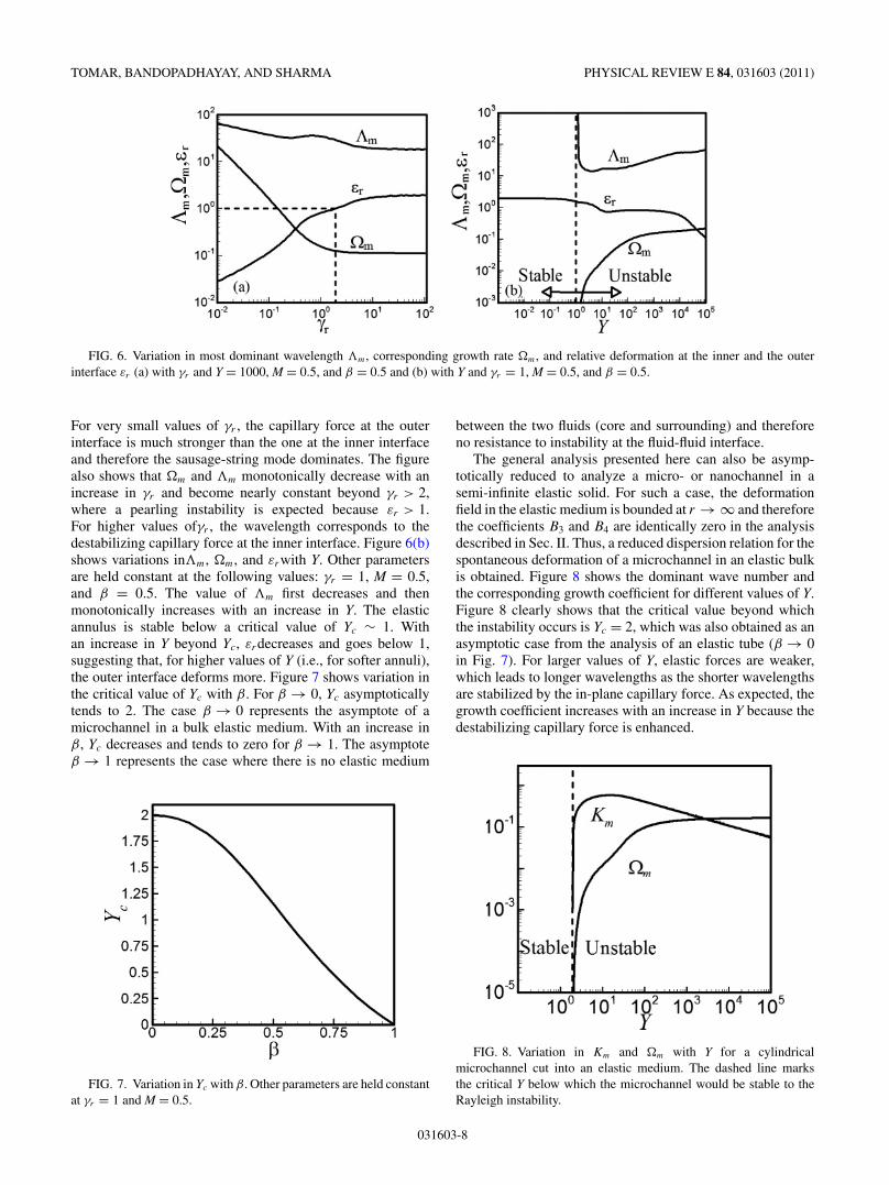
The other parameters that can significantly influence thetransition of the instability modes are the ratio of the interfacialtensions at the interfaces (γr ) and the ratio of the surfacetension to the elastic force (Y). Figure 6(a) shows the variationsinm, �m, and εrwith γr for β = 0.5, M = 0.5, and Y = 1000.For γr < 2, the value of εr < 1 suggests that the outer interfacedeforms more than the inner surface of the elastic annulus.
FIG. 5. (a)Variation in most dominant wavelength m, corresponding growth rate �m, and relative deformation at the inner and the outerinterface εr with M and Y = 1000, γr = 1, and β = 0.5. (b) Dispersion curves for M = 0.25 and 0.3 showing jump in the most dominantwavelength. The critical β for M = 0.33 is 0.5.
031603-7
TOMAR, BANDOPADHAYAY, AND SHARMA PHYSICAL REVIEW E 84, 031603 (2011)
FIG. 6. Variation in most dominant wavelength m, corresponding growth rate �m, and relative deformation at the inner and the outerinterface εr (a) with γr and Y = 1000, M = 0.5, and β = 0.5 and (b) with Y and γr = 1, M = 0.5, and β = 0.5.
For very small values of γr , the capillary force at the outerinterface is much stronger than the one at the inner interfaceand therefore the sausage-string mode dominates. The figurealso shows that �m and m monotonically decrease with anincrease in γr and become nearly constant beyond γr > 2,where a pearling instability is expected because εr > 1.For higher values ofγr , the wavelength corresponds to thedestabilizing capillary force at the inner interface. Figure 6(b)shows variations inm, �m, and εrwith Y. Other parametersare held constant at the following values: γr = 1, M = 0.5,and β = 0.5. The value of m first decreases and thenmonotonically increases with an increase in Y. The elasticannulus is stable below a critical value of Yc ∼ 1. Withan increase in Y beyond Yc, εrdecreases and goes below 1,suggesting that, for higher values of Y (i.e., for softer annuli),the outer interface deforms more. Figure 7 shows variation inthe critical value of Yc with β. For β → 0, Yc asymptoticallytends to 2. The case β → 0 represents the asymptote of amicrochannel in a bulk elastic medium. With an increase inβ, Yc decreases and tends to zero for β → 1. The asymptoteβ → 1 represents the case where there is no elastic medium
FIG. 7. Variation in Yc with β. Other parameters are held constantat γr = 1 and M = 0.5.
between the two fluids (core and surrounding) and thereforeno resistance to instability at the fluid-fluid interface.
The general analysis presented here can also be asymp-totically reduced to analyze a micro- or nanochannel in asemi-infinite elastic solid. For such a case, the deformationfield in the elastic medium is bounded at r → ∞ and thereforethe coefficients B3 and B4 are identically zero in the analysisdescribed in Sec. II. Thus, a reduced dispersion relation for thespontaneous deformation of a microchannel in an elastic bulkis obtained. Figure 8 shows the dominant wave number andthe corresponding growth coefficient for different values of Y.Figure 8 clearly shows that the critical value beyond whichthe instability occurs is Yc = 2, which was also obtained as anasymptotic case from the analysis of an elastic tube (β → 0in Fig. 7). For larger values of Y, elastic forces are weaker,which leads to longer wavelengths as the shorter wavelengthsare stabilized by the in-plane capillary force. As expected, thegrowth coefficient increases with an increase in Y because thedestabilizing capillary force is enhanced.
FIG. 8. Variation in Km and �m with Y for a cylindricalmicrochannel cut into an elastic medium. The dashed line marksthe critical Y below which the microchannel would be stable to theRayleigh instability.
031603-8

INSTABILITIES OF SOFT ELASTIC MICROTUBES . . . PHYSICAL REVIEW E 84, 031603 (2011)
FIG. 9. Variation in Km and �m with Y for a soft elastic fiber. Thedashed line shows the critical Y below which the microfiber is stableto the Rayleigh instability.
Another asymptotic system that can easily be analyzed fromthe general formulation shown in Sec. II is the deformationof an elastic fiber submerged in a bulk viscous fluid. Therenormalized dispersion relation is now obtained by setting thecoefficients B1 and B2 to zero because the terms multiplyingthese diverge as r → 0. The scaling parameters used here tostudy this case of a solid fiber are K = kRo, � = ωμsRo/γo
and Y = γo/(GeRo). Note that the radius and surface tensionof the outer surface of the annular cylinder, Ro, and theviscosity of the surrounding medium has been used fornondimensionalization. Figure 9 shows the dominant wavenumber and the corresponding growth rate as a function ofY. Interestingly, the trend is similar to that discussed earlierfor a micro- or nanochannel. However, the critical value of Ybelow which the fiber is stable is 6 as compared to 2 for amicrochannel in an elastic medium. The critical value of Y ishigher for an elastic fiber because it is less compliant comparedto the elastic bulk containing the microchannel. Interestingly,the critical value of Yc = 6 for the onset of instability inelastic fibers (Yc = 2 for a microchannel) is independent ofthe surrounding (core) viscous fluid. Figure 9 also shows thatthe critical wave number for an elastic fiber increases with anincrease in Y and asymptotically attains a value which can bepredicted purely based on the minimization of the free energy,neglecting the elastic energy penalty (kcRo = 1). This is notsurprising because, in the limit of zero shear modulus, theelastic fibers would behave like an inviscid fluid and deformwithout any resistance. This also validates our linear stabilityanalysis results.
V. CONCLUSIONS
We performed a linear stability analysis (LSA) on aninitially quiescent system to show that, below a critical shearmodulus [Y = γi/(GeRi) > 1 for γr = 1, M = 0.5, andβ = 0.5], an elastic annulus is unstable and may show oneof the following modes of instability: (i) a pearling instabilitywhere the inner interface deforms more that the outer interface,(ii) sausage strings with the formation of beads when the outer
interface deforms more and may even lead to the breakup ofthe annulus into rings, and (iii) wrinkling when the wall ofthe annulus is thin and both inner and outer interfaces deformequally (see Fig. 2). Instability is the result of a competitionbetween the elastic penalty due to deformation in the tube andthe destabilizing radial curvature at the inner and the outerinterfaces. Both the inner interface of the annulus and theouter interface have different characteristic lengths, and kineticeffects choose the dominant mode.
Based on the results from linear stability analysis, we showthat a thicker elastic tube would show breakup of the innerfluid cylinder into a string of pearls or a peapod, whereas anextremely thinner elastic tube shows bending modes (wrin-kling) with shorter wavelengths. In the intermediate regimeone would observe the formation of sausage strings with theouter surface deforming more than the inner interface. Suchinstabilities have been observed in the breakup of polymernanotubes into capsules and in blood vesicles, which show theformation of sausage strings [18].
We also show that a thin microchannel in an elastic bulkcan be stable and rupture into thin spherical cavities if theparameter Y is greater than 2. A thin soft elastic fiber wouldbreak up into droplets like a liquid jet if the parameter Y isgreater than 6. With the advent of nanomanufacturing andthe miniaturization of existing systems to enhance efficiencyand reduce power consumption, the present study providesguidelines for designing stable microfibers, microtubes, andmicrovessels.
ACKNOWLEDGMENTS
Discussions with V. Shankar, IITK, are gratefully acknowl-edged. The support of Ministry of Education, Science andTechnology, South Korea under the World Class University(WCU) is acknowledged by Ashutosh Sharma under programR32-2008-000-20082-0.
APPENDIX
The dispersion relation can be written in the determinantform: ∣∣∣∣∣∣∣∣∣∣∣∣
a11 a12 · · · a17 a18
a21 a28
.... . .
...
a71 a78
a81 a82 . . . a87 a88
∣∣∣∣∣∣∣∣∣∣∣∣= 0.
The nonzero components of the matrix are given in termsof the modified Bessel functions of the first and second kind:
a13 = [�K0(K/β)]/β, a14 = �K1(K/β),
a15 = [�I0(K/β)]/β, a16 = �I1(K/β),
a17 = −[K0(K/β)]/β, a18 = −K1(K/β),
a21 = −I0(K), a22 = −I1(K), a23 = �K0(K),
a24 = �K1(K), a25 = �I0(K), a26 = �I1(K),
031603-9

TOMAR, BANDOPADHAYAY, AND SHARMA PHYSICAL REVIEW E 84, 031603 (2011)
a33 = �[2βK0(K/β) − KK1(K/β)]
β2,
a34 = −K�K0(K/β)
β, a35 = �[2βI0(K/β) + KI1(K/β)]
β2,
a36 = K�I0(K/β)
β, a37 = −2βI0(K/β) + KI1(K/β)
β2,
a38 = KK0(K/β)
β,
a41 = −2I0(K) − KI1(K), a42 = −KI0(K),
a43 = �[2K0(K) − KK1(K)],
a44 = −K�K0(K), a45 = �[2I0(K) + KI1(K)],
a46 = K�I0(K),
a53 = 2K[KK0(K/β) − βK1(K/β)]
Yβ,
a54 = 2K2K1(K/β)
Y, a55 = 2K[KI0(K/β) + βI1(K/β)]
Yβ,
a56 = 2K2I1(K/β)
Y,
a57 = 2K(M − 1)[KK0(K/β) − βK1(K/β)]
Mβ,
a58 = 2K2(M − 1)K1(K/β)
M,
a61 = −2K[KI0(K) + I1(K)], a62 = −2K2I1(K),
a63 = 2K[KK0(K) − K1(K)]
Y,
a64 = 2K2K1(K)
Y, a65 = 2K[KI0(K) + I1(K)]
Y,
a66 = 2K2I1(K)
Y,
a73 = 2KK1(K/β)
Yβ, a74 = 2[KK0(K/β) + βK1(K/β)]
Y, a75 = −2KI1(K/β)
Yβ,
a76 = 2[−KI0(K/β) + βI1(K/β)]
Y, a77 = M(β2 − K2)K0(K/β) + 2K(M − 1)γr�K1(K/β)
Mβγr�,
a78 = 2K(M − 1)γr�K0(0,K/β) + [−K2M + β(Mβ − 2γr� + 2Mγr�)]K1(1,K/β)
Mγr�,
a81 = − (K2 − 1)I0(K) + 2K�I1(K)
�, a82 = −2K�I0(K) + (1 − K2 + 2�)I1(K)
�, a83 = −2KK1(K)
Y,
a84 = −2[KK0(K) + K1(K)]
Y, a85 = 2KI1(K)
Y, a86 = 2[KI0(K) − I1(K)]
Y.
[1] M. W. J. Prins, W. J. J. Welters, and J. W. Weekamp, Science291, 277 (2001).
[2] M. A. Unger, H. Chou, T. Thorsen, A. Scherer, and S. R. Quake,Science 288, 113 (2000).
[3] G. M. Whitesides and A. D. Stroock, Phys. Today 54, 42 (2001).[4] D. V. McAllister, M. G. Allen, and M. R. Prausnitz, Annual
Review of Biomedical Engineering 2, 289 (2000).[5] M. R. Abidian, D. H. Kim, and D. C. Martin, Advanced Materials
18, 405 (2006).[6] A. Migliore, F. Vozzi, G. Vozzi, and A. Ahluwalia, Biomed
Microdevices 10, 81 (2008).[7] R. Dersch, M. Steinhart, U. Boudriot, A. Greiner, and J. H.
Wendorff, Polym. Adv. Technol. 16, 276 (2005).[8] J. Jang, S. Ko, and Y. Kim, Adv. Funct. Mater. 16, 754 (2006).[9] K. Sekimoto and K. Kawasaki, J. Phys. Soc. Jpn. 56, 2997
(1987).[10] A. Onuki, Phys. Rev. A 39, 5932 (1989).[11] E. S. Matsuo and T. Tanaka, J. Chem. Phys. 89, 1695 (1988).[12] E. S. Matsuo and T. Tanaka, Nature (London) 358, 482 (1992).
[13] P. Nelson, T. Powers, and U. Seifert, Phys. Rev. Lett. 74, 3384(1995).
[14] B. Barriere, K. Sekimoto, and L. Leibler, J. Chem. Phys. 105,1735 (1996).
[15] D. E. Discher and A. Eisenberg, Science 297, 967 (2002).[16] Q. He, W. Song, H. Mohwald, and J. Li, Langmuir 24, 5508
(2008).[17] I. Tsafrir, Y. Caspi, M. Guedeau-Boudeville, T. Arzi, and
J. Stavans, Phys. Rev. Lett. 91, 138102 (2003).[18] P. Alstrøm, V. M. Eguıluz, M. Colding-Jørgensen, F. Gustafsson,
and N. Holstein-Rathlou, Phys. Rev. Lett. 82, 1995 (1999).[19] J. Xie, X. Li, and Y. Xia, Macromol Rapid Commun. 29, 1775
(2008).[20] D. H. Reneker and I. Chun, Nanotechnology 7, 216 (1996).[21] K. Autumn, Y. A. Liang, S. T. Hsieh, W. Zesch, W. P. Chan,
T. W. Kenny, R. Fearing, and R. J. Full, Nature (London) 405,681 (2000).
[22] T. S. Kustandi, V. D. Samper, D. K. Yi, W. S. Ng, P. Neuzil, andW. Sun, Adv. Funct. Mater. 17, 2211 (2007).
031603-10
INSTABILITIES OF SOFT ELASTIC MICROTUBES . . . PHYSICAL REVIEW E 84, 031603 (2011)
[23] N. J. Glassmaker, A. Jagota, C.-Y. Hui, and J. Kim, J. R. Soc.Interface 1, 23 (2004).
[24] M. T. Northen, C. Greiner, E. Arzt, and K. L Turner, Adv. Mater.20, 3905 (2008).
[25] D. Chandra and S. Yang, Langmuir 25, 10430 (2009).[26] J. W. Strutt and Lord Rayleigh, Philosophical Magazine Ser. 5
34, 177 (1892).[27] J. Plateau, Acad. Sci. Bruxelles Mem. 23, 5 (1849).[28] Lord Rayleigh, Proc. Roy. Soc. Lond. 29, 71 (1879).[29] J. Eggers and E. Villermaux, Rep. Prog. Phys. 71, 036601 (2008).[30] M. S. McCallum, P. W. Voorhees, M. J. Miksis, S. H. Davis, and
H. Wong, J. Appl. Phys. 79, 7604 (1996).[31] F. Yang and W. Song, Int. J. Solid Struct. 43, 6767 (2006).[32] A. Ghatak, M. Chaudhury, V. Shenoy, and A. Sharma, Phys.
Rev. Lett. 85, 4329 (2000).[33] V. Shenoy and A. Sharma, Phys. Rev. Lett. 86, 119 (2001).[34] W. Monch and S. Herminghaus, Europhys. Lett. 53, 525 (2001).[35] V. Shenoy and A. Sharma, J. Mech. and Phys. Solids 50, 1155
(2002).[36] C. Q. Ru, J. Appl. Mech. 69, 97 (2002).[37] H. Hsueh and P. Miranda, J. Mater. Res. 18, 1275 (2003).[38] R. E. Webber and K. R. Shull, Phys. Rev. E 68, 021805 (2003).[39] S. Kumar, Langmuir 19, 2473 (2003).[40] S. Kumar and O. K. Matar, J. Colloid Interface Sci. 273, 581
(2004).[41] J. Sarkar, V. Shenoy, and A. Sharma, Phys. Rev. Lett. 93, 018302
(2004).[42] G. F. Wang, P. Schiavone, and C. Q. Ru, Acta Mechanica 180, 1
(2005).[43] O. K. Matar, V. Gkanis, and S. Kumar, J. Colloid Interface Sci.
286, 319 (2005).[44] S.-Q. Huang, Q.-Y. Li, X.-Q. Feng, and S.-W. Yu, Mechanics Of
Materials 38, 88 (2006).[45] S. J. Kwon, J. App. Phys. 99, 063503 (2006).
[46] S. J. Kwon and J. G. Park, J. Phys. Chem. C 111, 4404 (2007).[47] C. D. Coman and A. P. Bassom, J. Mech. Phys. Solids 55, 1601
(2007).[48] H. Zeng, Y. Tian, B. Zhao, M. Tirrell, and J. Israelachvili,
Macromolecules 40, 8409 (2007).[49] J. Sarkar, V. Shenoy, and A. Sharma, Phys. Rev. E 77, 031604
(2008).[50] C. C. Lin, F. Q. Yang, and S. Lee, Langmuir 24, 13627 (2008).[51] J. Nase, A. Lindner, and C. Creton, Phys. Rev. Lett. 101, 074503
(2008).[52] D. Bandyopadhyay, A. Sharma, and V. Shankar, J. Chem. Phys.
128, 154909 (2008).[53] D. Bandyopadhyay, A. Sharma, U. Thiele, and P. D. S. Reddy,
Langmuir 25, 9108 (2009).[54] X.-H. Pan, S.-Q. Huang, S.-W. Yu, and X.-Q. Feng, J. of Phys.
D-App. Phys. 42, 055302 (2009).[55] L. H. He and K. Li, Thin Solid Films 518, 3853 (2010).[56] C. W. Lim and X. S. Xu, App. Mech. Rev. 63, 050802 (2010).[57] D. Bandyopadhyay, A. Sharma, and V. Shankar, Euro. Phys.
Lett. 89, 36002 (2010).[58] B. Li, H. P. Zhao, and X. Q. Feng, J. Mech. and Phys. Solids 59,
610 (2011).[59] N. Arun, A. Sharma, V. Shenoy, and K. S. Narayan, Adv.
Materials 18, 660 (2006).[60] J.-Y. Chung, K. Kim, M. K. Chaudhury, J. Sarkar, and
A. Sharma, Euro. Phys. J. E 20, 47 (2006).[61] M. Gonuguntala, A. Sharma, J. Sarkar, S. A. Subramanian,
M. Ghosh, and V. Shenoy, Phys. Rev. Lett. 97, 018303 (2006).[62] M. Gonuguntala, A. Sharma, R. Mukherjee, and S. A.
Subramanian, Langmuir 22, 7066 (2006).[63] R. Mukherjee, R. Pangule, A. Sharma, and G. Tomar, Adv. Func.
Mat. 17, 2356 (2007).[64] N. Arun, A. Sharma, P. S. G. Pattader, I. Banerjee, H. M. Dixit,
and K. S. Narayan, Phys. Rev. Lett. 102, 254502 (2009).
031603-11