Design of a flexible rockfall barrier using explicit dynamic ...
Upload
khangminh22Category
view
0download
0
Slope Stability 2013 – P.M. Dight (ed) © 2013 Australian Centre for Geomechanics, Perth, ISBN 978-0-9870937-5-2
Slope Stability 2013, Brisbane, Australia 1245
West Gully Upper – innovative rockfall and debris flow protection systems
H.P. Anderson Geovert Ltd, New Zealand
A. Teen Geovert Global PTE, Singapore
H. Salzmann Free Fall Geotechnical Engineering ZT GmbH, Austria
Abstract
Within PT Freeport Indonesia’s (PTFI) mining operation in Papua, Indonesia the Mill Area complex is subject to rockfall and debris flow events which initiate from a source area approximately 1,000 m up in a steep gully known as the ‘West Gully’. Active barrier protection systems, RXI-500 (5,000 kJ) barrier, were installed to reduce likelihood of these geohazards impacting the Mill Area. However, during August 2011 an estimated 45,000 m³ failure event occurred from the West Gully Upper source area due to differential erosion and the sites tectonic setting. The mass and velocity of this failure easily exceeded the capacity of the two RX-500 barriers located in the lower section of the gully. The failure event caused significant damage and economic interruption to the Mill Area complex and blocked the critical transport corridor (Ridwan Napitupulu Road).
Following a site visit Geovert provided an options report and formally recommended increasing the overall capacity of the rockfall/debris flow protection system for the West Gully by significantly increasing individual barrier capacity from 5,000 to 8,000 kJ. PTFI as a true industry innovator committed to the GBE-8000A system prior to public knowledge of its existence and prior to the system achieving certification at the Swiss Governmental testing facility in Walenstadt. Certification was later achieved at Walenstadt in October 2011. Free Fall Geotechnical Engineering ZT GmbH modelled rockfall and debris flow anticipated trajectories and impact forces for the West Gully protection system. This modelling supported recommendations to increase the protection system capacity utilising GBE-8000A barrier technology. Rockfall 7.1 beta, by Dr. Spang Ltd, modelling confirmed 3 locations for GBE-8000A barriers to suitability retain rockfall and debris flow events in the West Gully. The proposal included provision for installation of temporary protection works to protect against geohazards while constructing barrier’s in the West Gully and contingency planning to allow for safe repair works of barrier systems if a major failure event occurs. Climatic, environmental and physical conditions were critical in pre-construction planning and during construction execution to compensate for; frequent heavy bursts of precipitation (estimated at 11 m/yr at the Mill Area complex), consideration of the project site situated at approximately 3,600 masl and no road access to the site resulting in complete reliance on tailored Helicopter transportation of all personnel, equipment and materials to site.
1 Project background
1.1 Introduction
Freeport McMoRan Copper & Gold Inc. subsidiary PT Freeport Indonesia – (PTFI) conducts its mining operation in the remote highlands of the Sudirman Mountain Range in the province of Papua, Indonesia. Mining operations include open pit and underground ore extraction from one of the world’s largest recoverable copper and the largest gold reserve. All extracted ore is primarily crushed onsite then it is transported to the Mill Area (MP72) to undergo further crushing, grinding and flotation to produce a copper–gold concentrate. This concentrate is mixed to form a slurry to allow piping down to the port at Amamapare where it is shipped to smelters.
doi:10.36487/ACG_rep/1308_88_Anderson

West Gully Upper – innovative rockfall and debris flow protection systems H.P. Anderson et al.
1246 Slope Stability 2013, Brisbane, Australia
1.2 Problem definition
A steep gully (West Gully) approximately 1,000 m above the Mill Area complex has, for several years, been releasing boulders (generally >1 m size) and considerable loose material in the form of rockfall and debris flows. Geovert has previously been contracted by PTFI to construct two RXI-500 (5,000 kJ) rockfall protection barriers in the mid and lower West Gully, directly above the Mill Area complex. Barrier modelling was carried out as presented in the ‘Rockfall protection of ore processing facilities in Papua – Design and implementation of high energy flexible rockfall barrier’ paper by Salzmann et al. (2010). In August 2011 a significant rockfall/debris flow failure event occurred, estimated in size as 45,000 m³ This topple-planar type failure event experienced significant momentum in the West Gully which easily exceeded the capacity of the two existing RXI-500 (5,000 kJ) barriers situated at mid and lower gully levels. The mid gully level RXI-500 barrier was significantly damaged by high impact forces and due to the large volume of material while the lower RXI-500 barrier was buried with rock and debris easily overtopping it and continuing down to inundate the Ridwan Napitupulu Road and impact Mill Area complex. This event caused disruption to the PTFI Mill Area operations, damage to Mill Area assets, and compromised the safety of personnel prompting greater concern for mine personnel and property.
1.3 Proposal and project feasibility
Multiple site visits were carried out to inspect the West Gully project site following the August 2011 rockfall/debris flow event. During a site visit Geovert gave a presentation recommending use of Geobrugg prototype 8,000 kJ barrier system, to provide permanent protection against rockfall and debris flow hazards, although this barrier was still to be officially certified. Freefall Geohazard Solutions ZT GmbH were commissioned to give supporting assessment for developing the largest barrier protection system (8,000 kJ) soon to be available on the market. An options report (the proposal) was then presented for this protection system solution to PTFI. PTFI placed a purchase order for the first 8,000 kJ barrier system (GBE−8000A) prior to the official certification in Switzerland. Geobrugg achieved the required certification at the Swiss Governmental testing facility in Walenstadt in October 2011 with a category A ETAG 27 awarded. See reference to the GBE-8000A rockfall protection barrier (Geobrugg, 2011).
The proposal included provision for temporary protection works to protect workers from rockfall while constructing these permanent barriers in the West Gully. Temporary protection targeted geohazards from both the West Gully Upper source area and the ridge-line above. In addition, early in 2012 a near miss rockfall event sourced from the heavily vegetated ridge-line above the West Gully Upper source area lead to the exposure of further unstable rock requiring treatment. Most of this unstable rock was identified under vegetation and soil cover.
Key considerations during the feasibility stage was risk management and contingency of geohazards to the Mill Area complex. Focus was on developing a robust series of rockfall and debris flow protection barriers capable of withstanding large volume and high failure impact events, namely design, development and installation of the 8,000 kJ barriers. Contingency planning considered the ‘what if’ scenario focusing on continued protection for the Mill Area complex and repair crews following a significant failure event, i.e. replacement of damaged barrier elements such as mesh panels and posts would render that barrier ineffective during the repair process.
The West Gully project is a test piece show-casing to the latest innovative design and engineering solutions available to for asset protection against large scale geohazards. This project involves significant site specific challenges considering construction is executed in one of the world’s most remote and challenging environments (Section 3).
1.4 West Gully site layout – proposed protection works
The West Gully project site is essentially divided into the three main work packages representing solutions for particular areas as annotated in Figure 1 and outlined below:

Wall control
Slope Stability 2013, Brisbane, Australia 1247
Figure 1 An oblique aerial photo of the eastern aspect of this range showing the West Gully project site: Ridge-line protection works, West Gully Upper source area, west gully track and run-out into the Mill Area production plant complex. Existing SPIDER® NET S4-230 (Geobrugg, 2013) installation of ridge-line and West Gully source area are annotated by the yellow outlined areas. Proposed locations are annotated for the GBE−8000 (8,000 kJ) debris flow and rockfall barriers. The West Gully upper camp is on the western aspect of this range (other side over the ridgeline)
GBE-8000A debris flow barrier. Approx. elev. 3,460 masl
GBE-8000A rockfall barrier 1. Approx. elev. 3,150 masl
GBE-8000A rockfall barrier 2. Approx. elev. 3,050 masl
West Gully Upper source area. Approx. elev. 3,600 to 3,500 masl
Ridge-line protection works area. Approx. elev. 3,680 masl
Source Area
Track and secondary source area
Run-out area
Mill Area Complex
Ridwan Napitupulu Road. Approx. elev. 2,920 masl
West Gully Upper – innovative rockfall and debris flow protection systems H.P. Anderson et al.
1248 Slope Stability 2013, Brisbane, Australia
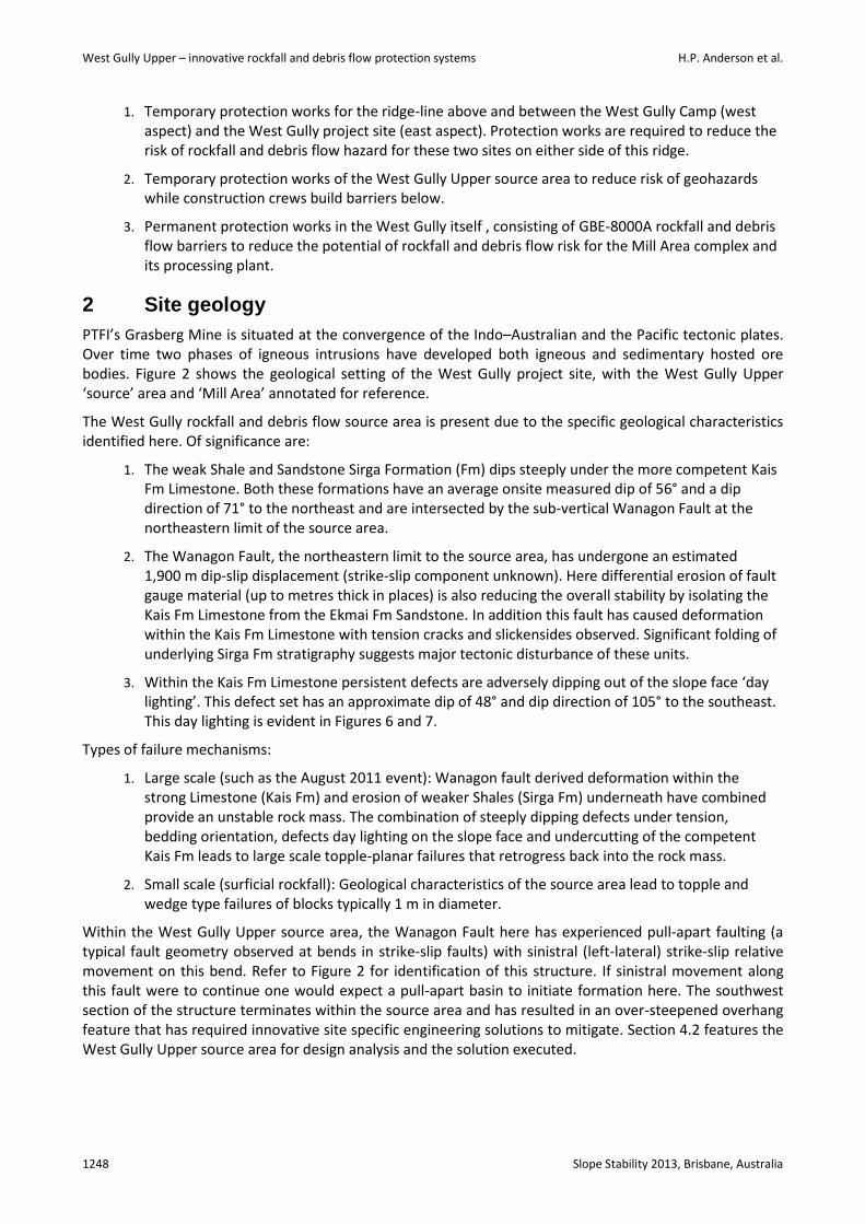
1. Temporary protection works for the ridge-line above and between the West Gully Camp (west aspect) and the West Gully project site (east aspect). Protection works are required to reduce the risk of rockfall and debris flow hazard for these two sites on either side of this ridge.
2. Temporary protection works of the West Gully Upper source area to reduce risk of geohazards while construction crews build barriers below.
3. Permanent protection works in the West Gully itself , consisting of GBE-8000A rockfall and debris flow barriers to reduce the potential of rockfall and debris flow risk for the Mill Area complex and its processing plant.
2 Site geology
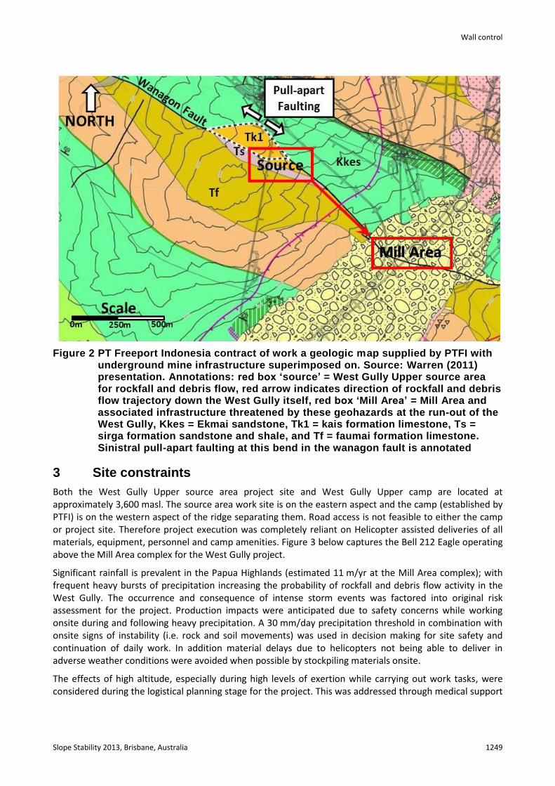
PTFI’s Grasberg Mine is situated at the convergence of the Indo–Australian and the Pacific tectonic plates. Over time two phases of igneous intrusions have developed both igneous and sedimentary hosted ore bodies. Figure 2 shows the geological setting of the West Gully project site, with the West Gully Upper ‘source’ area and ‘Mill Area’ annotated for reference.
The West Gully rockfall and debris flow source area is present due to the specific geological characteristics identified here. Of significance are:
1. The weak Shale and Sandstone Sirga Formation (Fm) dips steeply under the more competent Kais Fm Limestone. Both these formations have an average onsite measured dip of 56° and a dip direction of 71° to the northeast and are intersected by the sub-vertical Wanagon Fault at the northeastern limit of the source area.
2. The Wanagon Fault, the northeastern limit to the source area, has undergone an estimated 1,900 m dip-slip displacement (strike-slip component unknown). Here differential erosion of fault gauge material (up to metres thick in places) is also reducing the overall stability by isolating the Kais Fm Limestone from the Ekmai Fm Sandstone. In addition this fault has caused deformation within the Kais Fm Limestone with tension cracks and slickensides observed. Significant folding of underlying Sirga Fm stratigraphy suggests major tectonic disturbance of these units.
3. Within the Kais Fm Limestone persistent defects are adversely dipping out of the slope face ‘day lighting’. This defect set has an approximate dip of 48° and dip direction of 105° to the southeast. This day lighting is evident in Figures 6 and 7.
Types of failure mechanisms:
1. Large scale (such as the August 2011 event): Wanagon fault derived deformation within the strong Limestone (Kais Fm) and erosion of weaker Shales (Sirga Fm) underneath have combined provide an unstable rock mass. The combination of steeply dipping defects under tension, bedding orientation, defects day lighting on the slope face and undercutting of the competent Kais Fm leads to large scale topple-planar failures that retrogress back into the rock mass.
2. Small scale (surficial rockfall): Geological characteristics of the source area lead to topple and wedge type failures of blocks typically 1 m in diameter.
Within the West Gully Upper source area, the Wanagon Fault here has experienced pull-apart faulting (a typical fault geometry observed at bends in strike-slip faults) with sinistral (left-lateral) strike-slip relative movement on this bend. Refer to Figure 2 for identification of this structure. If sinistral movement along this fault were to continue one would expect a pull-apart basin to initiate formation here. The southwest section of the structure terminates within the source area and has resulted in an over-steepened overhang feature that has required innovative site specific engineering solutions to mitigate. Section 4.2 features the West Gully Upper source area for design analysis and the solution executed.
Wall control
Slope Stability 2013, Brisbane, Australia 1249
Figure 2 PT Freeport Indonesia contract of work a geologic map supplied by PTFI with underground mine infrastructure superimposed on. Source: Warren (2011) presentation. Annotations: red box ‘source’ = West Gully Upper source area for rockfall and debris flow, red arrow indicates direction of rockfall and debris flow trajectory down the West Gully itself, red box ‘Mill Area’ = Mill Area and associated infrastructure threatened by these geohazards at the run-out of the West Gully, Kkes = Ekmai sandstone, Tk1 = kais formation limestone, Ts = sirga formation sandstone and shale, and Tf = faumai formation limestone. Sinistral pull-apart faulting at this bend in the wanagon fault is annotated
3 Site constraints
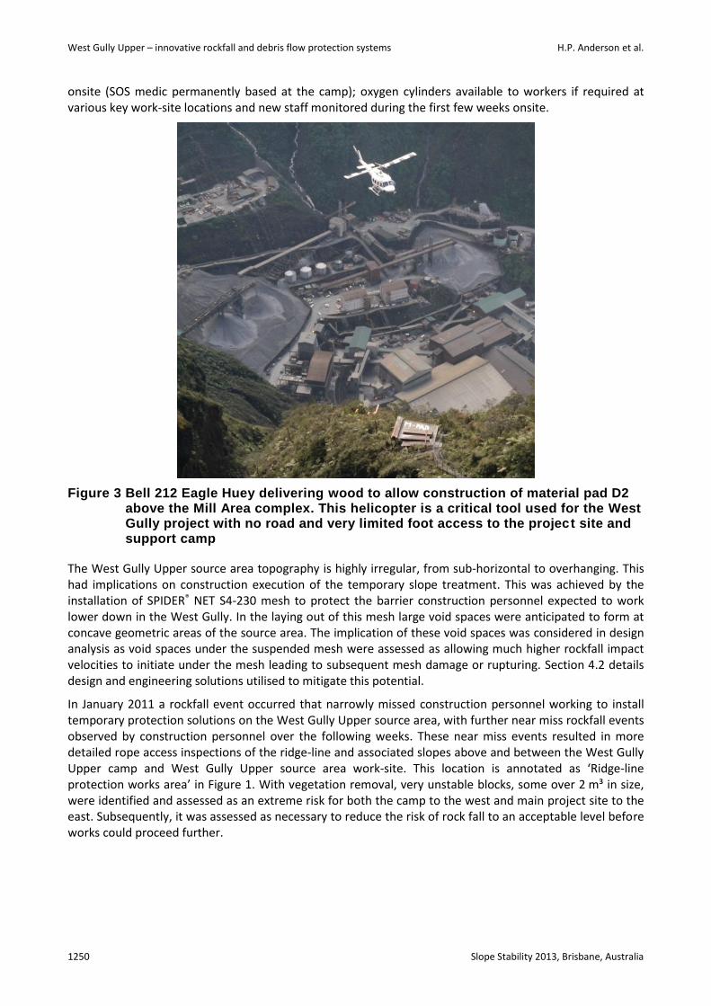
Both the West Gully Upper source area project site and West Gully Upper camp are located at approximately 3,600 masl. The source area work site is on the eastern aspect and the camp (established by PTFI) is on the western aspect of the ridge separating them. Road access is not feasible to either the camp or project site. Therefore project execution was completely reliant on Helicopter assisted deliveries of all materials, equipment, personnel and camp amenities. Figure 3 below captures the Bell 212 Eagle operating above the Mill Area complex for the West Gully project.
Significant rainfall is prevalent in the Papua Highlands (estimated 11 m/yr at the Mill Area complex); with frequent heavy bursts of precipitation increasing the probability of rockfall and debris flow activity in the West Gully. The occurrence and consequence of intense storm events was factored into original risk assessment for the project. Production impacts were anticipated due to safety concerns while working onsite during and following heavy precipitation. A 30 mm/day precipitation threshold in combination with onsite signs of instability (i.e. rock and soil movements) was used in decision making for site safety and continuation of daily work. In addition material delays due to helicopters not being able to deliver in adverse weather conditions were avoided when possible by stockpiling materials onsite.
The effects of high altitude, especially during high levels of exertion while carrying out work tasks, were considered during the logistical planning stage for the project. This was addressed through medical support
West Gully Upper – innovative rockfall and debris flow protection systems H.P. Anderson et al.
1250 Slope Stability 2013, Brisbane, Australia
onsite (SOS medic permanently based at the camp); oxygen cylinders available to workers if required at various key work-site locations and new staff monitored during the first few weeks onsite.
Figure 3 Bell 212 Eagle Huey delivering wood to allow construction of material pad D2 above the Mill Area complex. This helicopter is a critical tool used for the West Gully project with no road and very limited foot access to the project site and support camp
The West Gully Upper source area topography is highly irregular, from sub-horizontal to overhanging. This had implications on construction execution of the temporary slope treatment. This was achieved by the installation of SPIDER® NET S4-230 mesh to protect the barrier construction personnel expected to work lower down in the West Gully. In the laying out of this mesh large void spaces were anticipated to form at concave geometric areas of the source area. The implication of these void spaces was considered in design analysis as void spaces under the suspended mesh were assessed as allowing much higher rockfall impact velocities to initiate under the mesh leading to subsequent mesh damage or rupturing. Section 4.2 details design and engineering solutions utilised to mitigate this potential.
In January 2011 a rockfall event occurred that narrowly missed construction personnel working to install temporary protection solutions on the West Gully Upper source area, with further near miss rockfall events observed by construction personnel over the following weeks. These near miss events resulted in more detailed rope access inspections of the ridge-line and associated slopes above and between the West Gully Upper camp and West Gully Upper source area work-site. This location is annotated as ‘Ridge-line protection works area’ in Figure 1. With vegetation removal, very unstable blocks, some over 2 m³ in size, were identified and assessed as an extreme risk for both the camp to the west and main project site to the east. Subsequently, it was assessed as necessary to reduce the risk of rock fall to an acceptable level before works could proceed further.

Wall control
Slope Stability 2013, Brisbane, Australia 1251
4 Design analysis and engineering solutions
The West Gully project to date highlights the successful collaboration of various companies and their associated departments to provide innovative engineering solutions for significant site and design challenges encountered.
PTFI commissioned Geovert to carry out assessment, design and build best practice engineering solutions to provide adequate Mill Area protection for rockfall and debris flow events. Freefall Geotechnical Engineering ZT GmbH assisted in providing a robust protection system for the Mill Area complex. In addition temporary slope treatment was designed and engineering solutions implemented to provide a safe work environment for personnel constructing these permanent barriers.
To provide a robust engineering solution with contingency, design focused on a complete protection system rather than a single barrier. The recommended solution included:
1. Rockfall and debris flow source area treatment utilising SPIDER® NET S4-230 mesh dimensioned anchorage and drape system installation.
2. One Geobrugg GBE-8000A (8,000 kJ) debris flow barrier.
3. Two Geobrugg GBE-8000A (8,000 kJ) rockfall barriers.
A protection system that utilises multiple barriers as opposed to one single barrier provides greater risk reduction (detailed in Section 4.3 West Gully Rockfall and Debris Flow Protection Barriers).This contingency reduces overall risk for the Mill Area complex by considering the following:
1. During rockfall and debris flow failure event occurrence. This protection system provides three barriers to absorb impact forces and velocity of material at three locations along the West Gully alignment to halt its flow.
2. Following failure event occurrence. Significant repair works are possible on one or more barriers. Constructing a protection system that incorporates three separate barriers retains a level of protection for the Mill Area complex while one or two damaged barriers are repaired. Reliance on one barrier only could easily result in complete exposure of Mill Area complex to further impacts from rockfall and debris flow while it is under repair. Anticipated stability is expected to be questionable following a significant event.
The following is a summary of some of the key innovative solutions executed to date following a top down sequence mimicking the ‘top down’ safe work philosophy.
4.1 Protection works above West Gully Upper camp and project area
As previously discussed, unstable rock mass above the camp and project area was exposed following near−miss rockfall occurrences in early 2012. The extensive area of unstable rock was not identified until this point due to significant vegetation and soil-mass coverage.
Quantitative risk assessment indicated an extreme risk of rockfall for both the West Gully Upper camp and the West Gully project sites. Assessment was based on best practise and the industry accepted risk matrix that compares probability of a hazard occurring with the expected consequences. As with most hazards encountered in this industry, complete elimination is not possible or often financially unfeasible and therefore methods to reduce hazards are focused on. The two sites were assessed as extreme risk with potential for future rockfall impacting work-sites, camp amenities or site personnel (Wasson, 2012).
On identification and assessment both sites incurred an unacceptable risk potential with activity below to cease until the rockfall hazard is eliminated or reduced to as low as reasonably practical. Immediate mitigation was required with near 100% human habitation rates at the camp giving an extreme temporal probability of severe injury and/or fatality to camp personnel during potential rockfall events.
West Gully Upper – innovative rockfall and debris flow protection systems H.P. Anderson et al.
1252 Slope Stability 2013, Brisbane, Australia
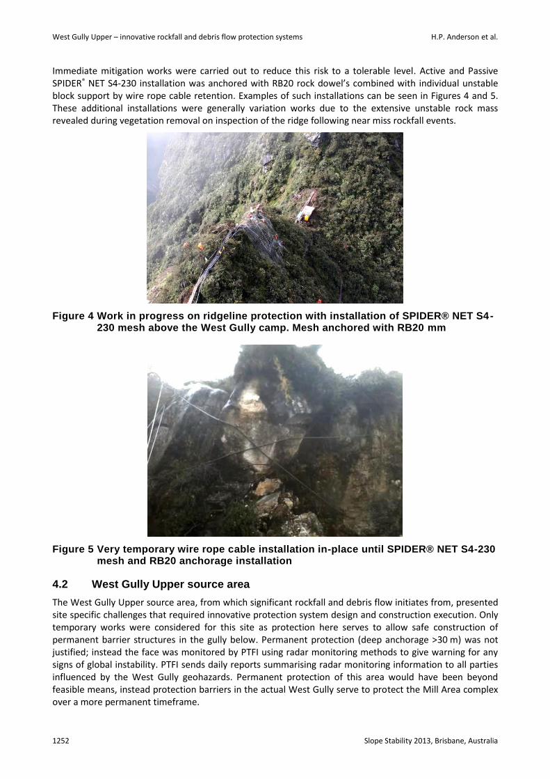
Immediate mitigation works were carried out to reduce this risk to a tolerable level. Active and Passive SPIDER® NET S4-230 installation was anchored with RB20 rock dowel’s combined with individual unstable block support by wire rope cable retention. Examples of such installations can be seen in Figures 4 and 5. These additional installations were generally variation works due to the extensive unstable rock mass revealed during vegetation removal on inspection of the ridge following near miss rockfall events.
Figure 4 Work in progress on ridgeline protection with installation of SPIDER® NET S4-230 mesh above the West Gully camp. Mesh anchored with RB20 mm
Figure 5 Very temporary wire rope cable installation in-place until SPIDER® NET S4-230 mesh and RB20 anchorage installation
4.2 West Gully Upper source area
The West Gully Upper source area, from which significant rockfall and debris flow initiates from, presented site specific challenges that required innovative protection system design and construction execution. Only temporary works were considered for this site as protection here serves to allow safe construction of permanent barrier structures in the gully below. Permanent protection (deep anchorage >30 m) was not justified; instead the face was monitored by PTFI using radar monitoring methods to give warning for any signs of global instability. PTFI sends daily reports summarising radar monitoring information to all parties influenced by the West Gully geohazards. Permanent protection of this area would have been beyond feasible means, instead protection barriers in the actual West Gully serve to protect the Mill Area complex over a more permanent timeframe.

Wall control
Slope Stability 2013, Brisbane, Australia 1253
To install effective temporary protection innovative thinking was required due to the source areas:
1. Significant size at approximately 6,800 m².
2. Irregular surface topography (varying from overhanging to sub-horizontal).
3. Unstable jointed Limestone rock (average 1 m³ size) from multiple locations within the West Gully Upper source area.
4. High load capacity potential from larger topple and planar failures, temporary protection works to minimise initiation of such failures in combination with PTFI monitoring for large scale movements.
Based on the above site characteristics temporary protection works required the highest load capacity mesh system on the market) and innovative solutions to minimise cost while providing a robust engineered solution for PTFI. Critical in this selection was protection against either or both failure potentials: multiple surficial rockfalls (1 m³ size) from a large area (6,800 m²) and larger topple-planar failures. Both standard types of mesh installation methodologies were considered and assessed:
1. Active mesh system: Mesh installation and dimension anchorage (pattern typically 3 × 3 m grid offset) of the entire West Gully Upper source area (6,800 m²). This system involves dimensioning rock dowel anchorage followed by the application of a mesh drape to create an active stabilisation pressure across the treated slope area. For localised rock fall events and stabilisation of boulders, this presents the most effective reduction of risk and control of hazards. However, it is time-consuming and subsequently increased the duration of risk exposure and is costly to construct.
2. Passive mesh drape system: Mesh drape installation with anchorage at top to secure the system and any additional rockfall activity loads under the mesh drape. The lack of dimensioning anchorage over the entire system means that a drape system does not apply an active restoring force to the slope but rather a passive stabilisation of boulders and loose rocks. Mesh drape serves to limit the velocities, and hence kinetic energy, of rockfall events underneath it.
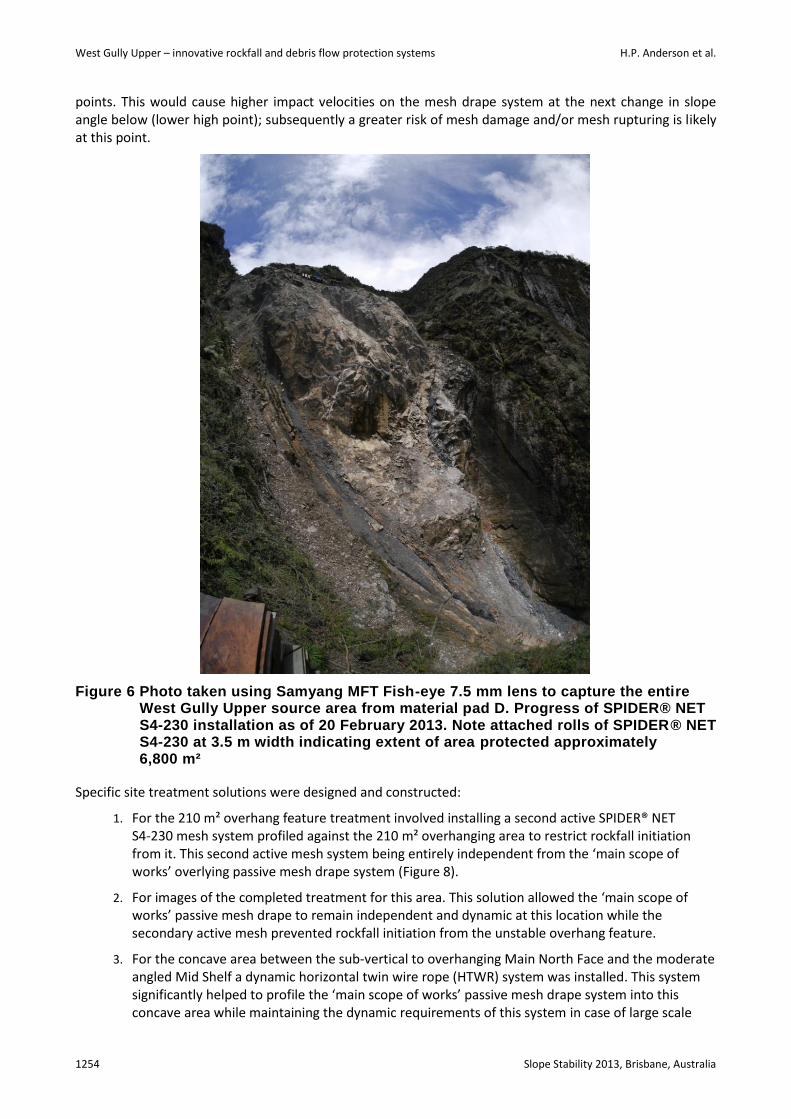
A combination of active and passive mesh systems was assessed as providing the best value while maintaining a tolerable level of temporary protection to allow permanent barrier construction works below. This is in combination with management of other site constraints, i.e. reducing site risk by restricting works in rockfall and debris flow run-out areas during high precipitation or during PTFI red alert radar warnings potentially indicating larger site movement. Detailed design analysis was carried out utilising standard anchor load assessment (BS8081) to determine the number of anchors required to support load from the mesh drape system and a 10 m³ design rockfall event. 180 rock dowels with an assumed worst case scenario of 1 m fixed bond length was calculated to resist these loads. A grid matrix of 25 rows and six to eight columns (dependant on site specific topography) provided the required 180 rock dowels. Figure 6 highlights progress of the mesh installation as of 20 February 2013.
Innovative engineering design solutions were required to support the mesh drape system and additional load during potential rockfall initiation behind the mesh drape system. As the mesh is dynamic in the vertical direction of pull the mesh drape and additional loading is not evenly distributed between all rock dowels in the anchorage grid matrix; load is mainly concentrated on the base row of rock dowels. To compensate for this, wire rope cables were installed from upper and mid rows down to the base row to evenly distribute this load over all rock dowel anchorages installed.
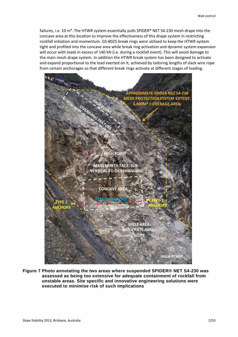
The 210 m² overhang feature formed by the pull-apart fault structure and the concave area at the base of the Main North Face required specific treatment to improve the mesh drape performance at these locations and to compensate for the significant face irregularities. During design analysis, the mesh drape system was anticipated to significantly span over high points at these two locations (Figure 7). A span of the mesh between such high points would form a void under this drape were any rockfall that initiates would be able to fall unrestricted and gain momentum under the mesh suspended between these two high
West Gully Upper – innovative rockfall and debris flow protection systems H.P. Anderson et al.
1254 Slope Stability 2013, Brisbane, Australia
points. This would cause higher impact velocities on the mesh drape system at the next change in slope angle below (lower high point); subsequently a greater risk of mesh damage and/or mesh rupturing is likely at this point.
Figure 6 Photo taken using Samyang MFT Fish-eye 7.5 mm lens to capture the entire West Gully Upper source area from material pad D. Progress of SPIDER® NET S4-230 installation as of 20 February 2013. Note attached rolls of SPIDER® NET S4-230 at 3.5 m width indicating extent of area protected approximately 6,800 m²
Specific site treatment solutions were designed and constructed:
1. For the 210 m² overhang feature treatment involved installing a second active SPIDER® NET S4-230 mesh system profiled against the 210 m² overhanging area to restrict rockfall initiation from it. This second active mesh system being entirely independent from the ‘main scope of works’ overlying passive mesh drape system (Figure 8).
2. For images of the completed treatment for this area. This solution allowed the ‘main scope of works’ passive mesh drape to remain independent and dynamic at this location while the secondary active mesh prevented rockfall initiation from the unstable overhang feature.
3. For the concave area between the sub-vertical to overhanging Main North Face and the moderate angled Mid Shelf a dynamic horizontal twin wire rope (HTWR) system was installed. This system significantly helped to profile the ‘main scope of works’ passive mesh drape system into this concave area while maintaining the dynamic requirements of this system in case of large scale
Wall control
Slope Stability 2013, Brisbane, Australia 1255
failures, i.e. 10 m³. The HTWR system essentially pulls SPIDER® NET S4-230 mesh drape into the concave area at this location to improve the effectiveness of this drape system in restricting rockfall initiation and momentum. GS-8025 break rings were utilised to keep the HTWR system tight and profiled into the concave area while break ring activation and dynamic system expansion will occur with loads in excess of 140 kN (i.e. during a rockfall event). This will avoid damage to the main mesh drape system. In addition the HTWR break system has been designed to activate and expand proportional to the load exerted on it, achieved by tailoring lengths of slack wire rope from certain anchorages so that different break rings activate at different stages of loading.
Figure 7 Photo annotating the two areas where suspended SPIDER® NET S4-230 was assessed as being too extensive for adequate containment of rockfall from unstable areas. Site specific and innovative engineering solutions were executed to minimise risk of such implications

West Gully Upper – innovative rockfall and debris flow protection systems H.P. Anderson et al.
1256 Slope Stability 2013, Brisbane, Australia
Figure 8 Two opposite perspectives highlighting the significant void space under the passive mesh drape system suspended due to the systems weight below. At annotated white point A the secondary active mesh system can be seen profiled in against the unstable jointed kais Fm limestone 201 m² overhang area
4.3 West Gully rockfall and debris flow protection barriers
Specific design was required for both the debris flow and rockfall barriers for this site. Prior to the West Gully Upper project, the greatest capacity barriers available on the market were Geobrugg’s RXI series that could withstand up to 5,000 kJ of impact energy. The two RXI-500 (5,000 kJ) rockfall barriers constructed in 2007, situated in themed and lower West Gully, were insufficient in retaining the 45,000 m³ rockfall/debris flow event that occurred during August 2011. Figures 9 to 11 highlight the extent of destruction from high impact forces that were experienced during the August 2011 event, easily exceeding the barrier’s 5,000 kJ capacity.
(a) (b) (c)
Figure 9 (a) Destroyed RXI-500; (b) activated breakrings; and (c) bent RXI post
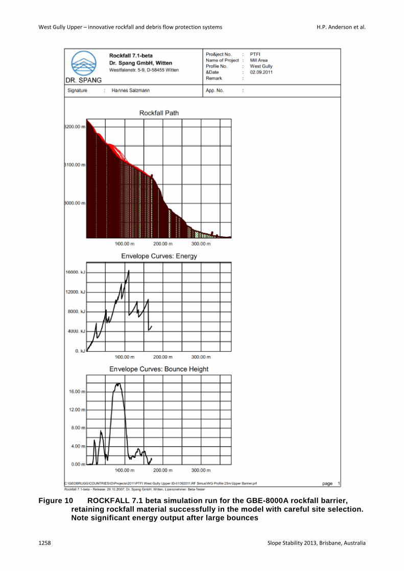
Rockfall modelling identified three ideal locations to construct 8,000 kJ barriers, as shown in Figure 1, in order to enhance Mill Area protection and overall system contingency. Software used was ROCKFALL 7.1 beta software by Dr. Spang GmbH. This 2D software was utilised due to the narrow characteristic of the West Gully; 3D modelling was not considered beneficial for this particular assessment. This modelling focused on the location of the three barriers (2 × rockfall and 1 × debris flow) to maximise catch effectiveness through assessing bounce height and impact energies for various size rockfall events. Figure 10 is an example of the ROCKFALL 7.1 beta simulation with the GBE-8000A Rockfall Barrier effectively retaining material.
The GBE-8000A barrier was designed to provide a more robust retainment system. The critical improvements of the GBE-8000A relative to its predecessor the RXI−500 include:
1. Inclusion of transmission ropes to dissipate forces during high impacts to a manageable level.
A
A

Wall control
Slope Stability 2013, Brisbane, Australia 1257
2. Newly developed U-Brake elements which work solely on plastic deformation, compared to the plastic-elastic deformation characteristics of the RXI Brake ring elements.
West Gully Upper – innovative rockfall and debris flow protection systems H.P. Anderson et al.
1258 Slope Stability 2013, Brisbane, Australia
Figure 10 ROCKFALL 7.1 beta simulation run for the GBE-8000A rockfall barrier, retaining rockfall material successfully in the model with careful site selection. Note significant energy output after large bounces
Wall control
Slope Stability 2013, Brisbane, Australia 1259
4 Conclusions
This project was commissioned by PTFI to Geovert Ltd to permanently protect the Mill Area complex at the base of the West Gully from geohazards (rockfall and debris flow) while maintaining a safe working environment for construction crews carrying out these works. Throughout this project the critical control was and still is safety and this is evident by the ‘top down’ philosophy adhered to in project stage planning and utilisation of IRATA standards on this work site. Herein, this paper follows the same sequential format.
Many innovative engineering solutions have been executed to date in order to overcome site specific challenges at the West Gully project site. Collaboration of various companies and departments has allowed successful project progress.
Site specific constraints were assessed in great detail during the design stage of this project, and these constraints are closely monitored onsite to allow for their successful management.
The West Gully Upper project site and associated camp amenities are situated at approximately 3,600 masl on very steep terrain with no road access to the remainder of the mine site. Therefore all personnel, equipment and material deliveries are completely reliant on tailored Bell 212 Eagle transportation. As expected for operations in Papua, Helicopter derived site access is influenced by weather conditions and therefore all Helicopter operations must be closely managed to avoid progress delays.
Temporary protection works have been carried out on the ridge-line above and between the West Gully Camp and West Gully project site to reduce rockfall risk to an acceptable level. This was achieved through a combination of active and passive SPIDER® NET S4-230 installations and individual securing of unstable blocks by wire rope retention cabling. Best value solutions were critical for this package of work as the significant source area for this geohazards was considered unforseen, on such a large scale. Initial feasibility failed to identify the extent of unstable rock mass with significant vegetation coverage and difficult terrain to inspect that limited estimate confidence. The seriousness of this hazard was exposed after a rockfall incident narrowly missed workers on the main West Gully project site. Subsequent vegetation removal along the ridge-line exposed further rockfall hazard’s that were assessed as extreme risk to both the West Gully project site and the associated camp and site access walkways.
Temporary protection works were designed and constructed for the West Gully Upper source area (top of the West Gully project site) to protect the construction sites of permanent protection systems further down gully. Temporary works included a combination of active dimensional and passive drape SPIDER® NET S4-230 mesh systems. Rock dowel dimensioned anchorage in the upper 21 m of the mesh system provides sufficient support for loading of the mesh drape system below with contingency for rockfall initiation under this drape system. In addition, wire rope connectors tensioned from upper and mid rows of rock dowels down to the lowest row helps to dissipate overall mesh drape load evenly over the dimensioned rock dowel anchorage area.
Two problematic areas, identified as the 210 m² overhang feature and the concave area at the base of the Main North Wall, required specific treatment. This was necessary to avoid formation of a large void spaces under the mesh drape system due to its suspension on irregular slope surfaces. An excessive void space under the mesh drape system allows high impact velocities for any rockfall initiated and has the potential to rupture the drape system at the next change in slope angle below. Key innovative solutions include:
1. A secondary active SPIDER® NET S4-230 mesh system was profiled to the 210 m² overhang feature to treat this area while being entirely independent from the main overlying passive mesh drape system. This solution allowed the overlying passive mesh drape system to remain dynamic while the secondary active mesh prevented rockfall initiation from the unstable overhang feature.
2. A specialised Horizontal Twin Wire Rope (HTWR) system was designed and built to treat the concave area under the Main North Face. The system profiled (pulled in) the main passive mesh drape into this concavity (restricting rockfall initiation and momentum under the mesh drape)

West Gully Upper – innovative rockfall and debris flow protection systems H.P. Anderson et al.
1260 Slope Stability 2013, Brisbane, Australia
while the use of break rings (Geobrugg GS-8025) in the system will allow the mesh drape to still function dynamically during any future large failures.
This project instigated an innovative upgrade in barrier protection technology with the development of the new and improved GBE-8000A barrier protection system. The rockfall/debris flow event observed during August 2011 easily exceeded anticipated event volumes which subsequently inundated and destroyed the two RXI-500 barriers installed to protect the Mill Area. A greater impact capacity system, the GBE-8000A (8,000 kJ) barrier, was designed to improve protection requirements for the Mill Area complex. ROCKFALL 7.1 beta modelling was used to assess the most effective positions for construction of the recommended GBE-8000A debris flow and two rockfall barriers.
A two-level debris flow barrier immediately below the West Gully Upper source area and two rockfall barriers at mid and low West Gully elevations are proposed to provide contingency for the Mill Area complex protection. This is anticipated to maintain Mill Area protection even after a significant rockfall/debris follow event and if subsequent maintenance is carried out on damaged sections of the protection system (i.e. upper debris flow barrier repairs).
Combining temporary and permanent engineering solutions provided a protection system that addresses the significant West Gully project site challenges. With continued collaboration and industry best practise methodologies utilised, a robust protection system is expected for PTFI’s Mill Area complex. On completion, this project is anticipated to show-case to the Slope Stability industry the effectiveness of these protection systems.
Acknowledgement
The authors are grateful to Geobrugg Geohazard Solutions and Freefall Geotechnical Engineering ZT GmbH, Switzerland, for continual consultation in all phases of this project.
The outstanding collaboration between PT Freeport and Geovert must also be acknowledged with gratitude. This positive work relationship has made this project possible in very challenging environment. Special thanks to Wahyu Sunyoto, Eman Widijanto, Munsi Nasution, Mike Swtawski, Paul Warren, Kamil Afrizal, Bagus Utama and the entire Geotechnical Department at PTFI.
References
Geobrugg (2011) 8000 kJ The Rockfall Barrier GBE-8000A withstands impact energy that would be too much for even concrete galleries to bear, GBE-8000A rockfall protection barrier, http://www.geobrugg.com/contento/Portals/35/media/Download-Brochures/Geobrugg-AG_GBE_8000A_en.pdf.
Geobrugg (2013) SPIDER NET S4-230, http://www.geobrugg.com/contento/Portals/35/media/Download-Brochures/Geobrugg-AG_SPIDER_Avalanche_en.pdf.
Salzmann, H., Roth, A. and Haller, B. (2010) Rockfall Protection of Ore Processing Facilities in Papua – Design and Implementation of High Energy Flexible Rockfall Barriers, in Proceedings 11th IAEG Congress, A.L. Williams, G.M. Pinches, C.Y. Chin, T.J. McMorran, C.I. Massey (eds), 5–10 September 2010, Auckland, New Zealand, CRC Press.
Warren, P.Q. (2011) The Upper West Gully Problem Area, PT Freeport – McMoran Copper & Gold, Tembagapura, Papua, PT Freeport-McMoran Copper & Gold, Tembagapura, Papua (unpublished presentation).
Wasson, Z. and Anderson, H.P. (2012) Options Report and Progress, 120315 – ZW – West Gully Scaling Make-Safe and Rock Fall Mitigation, Geovert Ltd (unpublished report).

Wall control
Slope Stability 2013, Brisbane, Australia 1261
Copyright © 2022 FDOKUMEN