Influence of vascular morphology on hemodynamic changes after flow diverter placement in saccular...
10
Influence of vascular morphology on hemodynamic changes after flow diverter placement in saccular intracranial aneurysms Ignacio Larrabide 1,2 , Arjan J. Geers 2,1 , Martha L. Aguilar 2,1 , Hern´ an G. Morales 2,1 , Daniel Rufenacht 3 , and Alejandro F. Frangi 2,1,4 1 Networking Research Center on Bioengineering, Biomaterials and Nanomedicine (CIBER-BBN), 08019 Barcelona, Spain 2 Universitat Pompeu Fabra, c/Tanger 122-140, 08018, Barcelona, Spain 3 Hirslanden Clinic, Zrich, Switzerland 4 Department of Mechanical Engineering, University of Sheffield, Sheffield, UK [email protected] Abstract. Flow diverter stents (FDs) are becoming widely used for the treatment of intracranial aneurysms, particularly for cases that present difficulties for other treatments such as coiling or clipping. The relation- ship between the surrounding vascular morphology and the effect of these devices on the changes of hemodynamic forces in the aneurysm, which has not been assessed so far, is studied in this paper. The Vascular Mod- eling Toolkit (VMTK) has been used for the characterization of vascular morphology. CFD simulations have been performed on untreated and virtually treated geometries of 16 saccular intracranial aneurysms. Our results indicate that distance of the aneurysm with respect to the pre- vious curvature peak of the vessel and the angle of the aneurysm with respect to the parent vessel osculating plane are closely related to the changes of hemodynamic variables inside the aneurysm after placement of a FD. Keywords: Intracranial aneurysm, vascular morphology, flow diverter, hemodynamics 1 Introduction FDs are stent-like devices designed to divert the flow along the normal anatom- ical course of the vessel and away from the aneurysm neck and dome. These devices have shown to be most useful in cases that are difficult to treat by other means [1]. Stagnation of the flow activity in the aneurysm stimulates thrombosis and, ultimately, occlusion of the aneurysm. This process induces reverse remod- eling of the aneurysm and reconstruction of the parent artery. Although animal experiments and clinical series have already shown impressive effectiveness of this technology, the effects on local hemodynamics are yet not fully understood [2]. Longer term persisting patency and delayed aneurysm ruptures have been re- ported in some cases after FD treatment. Still, complete angiographic occlusion Demirci, Lee, Radeva, Unal (Eds.): MICCAI-STENT 2012. 7
-
Upload
independent -
Category
Documents
-
view
3 -
download
0
Transcript of Influence of vascular morphology on hemodynamic changes after flow diverter placement in saccular...
Influence of vascular morphology onhemodynamic changes after flow diverter
placement in saccular intracranial aneurysms
Ignacio Larrabide1,2, Arjan J. Geers2,1, Martha L. Aguilar2,1, Hernan G.Morales2,1, Daniel Rufenacht3, and Alejandro F. Frangi2,1,4
1 Networking Research Center on Bioengineering, Biomaterials and Nanomedicine(CIBER-BBN), 08019 Barcelona, Spain
2 Universitat Pompeu Fabra, c/Tanger 122-140, 08018, Barcelona, Spain3 Hirslanden Clinic, Zrich, Switzerland 4 Department of Mechanical Engineering,
University of Sheffield, Sheffield, [email protected]
Abstract. Flow diverter stents (FDs) are becoming widely used for thetreatment of intracranial aneurysms, particularly for cases that presentdifficulties for other treatments such as coiling or clipping. The relation-ship between the surrounding vascular morphology and the effect of thesedevices on the changes of hemodynamic forces in the aneurysm, whichhas not been assessed so far, is studied in this paper. The Vascular Mod-eling Toolkit (VMTK) has been used for the characterization of vascularmorphology. CFD simulations have been performed on untreated andvirtually treated geometries of 16 saccular intracranial aneurysms. Ourresults indicate that distance of the aneurysm with respect to the pre-vious curvature peak of the vessel and the angle of the aneurysm withrespect to the parent vessel osculating plane are closely related to thechanges of hemodynamic variables inside the aneurysm after placementof a FD.
Keywords: Intracranial aneurysm, vascular morphology, flow diverter,hemodynamics
1 Introduction
FDs are stent-like devices designed to divert the flow along the normal anatom-ical course of the vessel and away from the aneurysm neck and dome. Thesedevices have shown to be most useful in cases that are difficult to treat by othermeans [1]. Stagnation of the flow activity in the aneurysm stimulates thrombosisand, ultimately, occlusion of the aneurysm. This process induces reverse remod-eling of the aneurysm and reconstruction of the parent artery. Although animalexperiments and clinical series have already shown impressive effectiveness ofthis technology, the effects on local hemodynamics are yet not fully understood[2]. Longer term persisting patency and delayed aneurysm ruptures have been re-ported in some cases after FD treatment. Still, complete angiographic occlusion
Demirci, Lee, Radeva, Unal (Eds.): MICCAI-STENT 2012. 7

2 I. Larrabide et al.
is reported in the majority of the cases [3–5]. The effectiveness of FD treatmentis related to factors ranging from physiology to the blood flow mechanics [6].
Proposals have been made for quantifying the effectiveness of the treatment(e.g., porosity, permeability) [7]. In this study, we relate the vascular morphol-ogy to the reduction in hemodynamic forces in the aneurysm after flow divertertreatment. Vascular morphology is studied and quantified following methodolo-gies proposed in previous studies [8, 9].
2 Material and Methods
Sixteen saccular aneurysms were used in this study and drawn from the @neurISTdatabase, which was collected in different centers and processed by different ob-servers following the same data processing protocol. All selected aneurysms werelocated at the supraclinoid segment of the ICA to reduce differences in parentvessel flow rate due. Anatomical models were obtained from diagnostic 3DRA im-ages, acquired through an IntegrisTM Allura System (Philips Healthcare, Best,The Netherlands) or an AXIOM Artis (Siemens Medical Solutions, Erlangen,Germany). Voxel sizes in the reconstructed 3D images ranged from 0.208 mm3
to 0.378 mm3.
Vascular extraction and geometric characterization
Images were segmented using a GAR method, and a 3D model consisting ofa triangulated surface mesh was generated [10]. Triangle removal, hole fillingand volume preserving optimized Laplacian smoothing were employed to re-move imperfections in the vascular models. GIMIAS software was used for theseoperations [11]. Vascular morphology was described in terms of centerline, vesseldiameter and curvature using the Vascular Modeling Toolkit (VMTK) package[9]. From the centerline, two variables were considered following the work ofPiccinelli et. al [9] (Fig. 1):
– Dpc: distance from the aneurysm ostium location over the centerline (originof the bifurcating branch going into the aneurysm) to the peak curvaturebefore the aneurysm.
– ao: angle between the aneurysm vector (vector pointing into the aneurysmof the local reference system defined in the aneurysm bifurcation) and thelocal osculating plane (defined form the local Frenet frame on the parentvessel at the location of the bifurcation).
Also, all vascular geometries where also characterized in terms of the length ofthe model lS , defined as the length between the proximal end of the ICA visiblefrom the model and the ICA bifurcation.
Virtual treatment and CFD analysis
Geometric models of the FDs, consisting of 48 wires of 60 µm thickness were cre-ated and deployed in the vascular models using the Fast Virtual Stenting method
Demirci, Lee, Radeva, Unal (Eds.): MICCAI-STENT 2012. 8

Assessment of vascular morphology effect on aneurysm treatment 3
Dpc
(a)
ao
(b)
lS
Fig. 1. (a) Graphical representation of the distance from the aneurysm neck to thecurvature peak measured along the centerline. The red dot represents the locationorigin in the aneurysm bifurcation. (b) Angle between the osculating plane (dark gray)and the aneurysm vector (green).
Demirci, Lee, Radeva, Unal (Eds.): MICCAI-STENT 2012. 9
4 I. Larrabide et al.
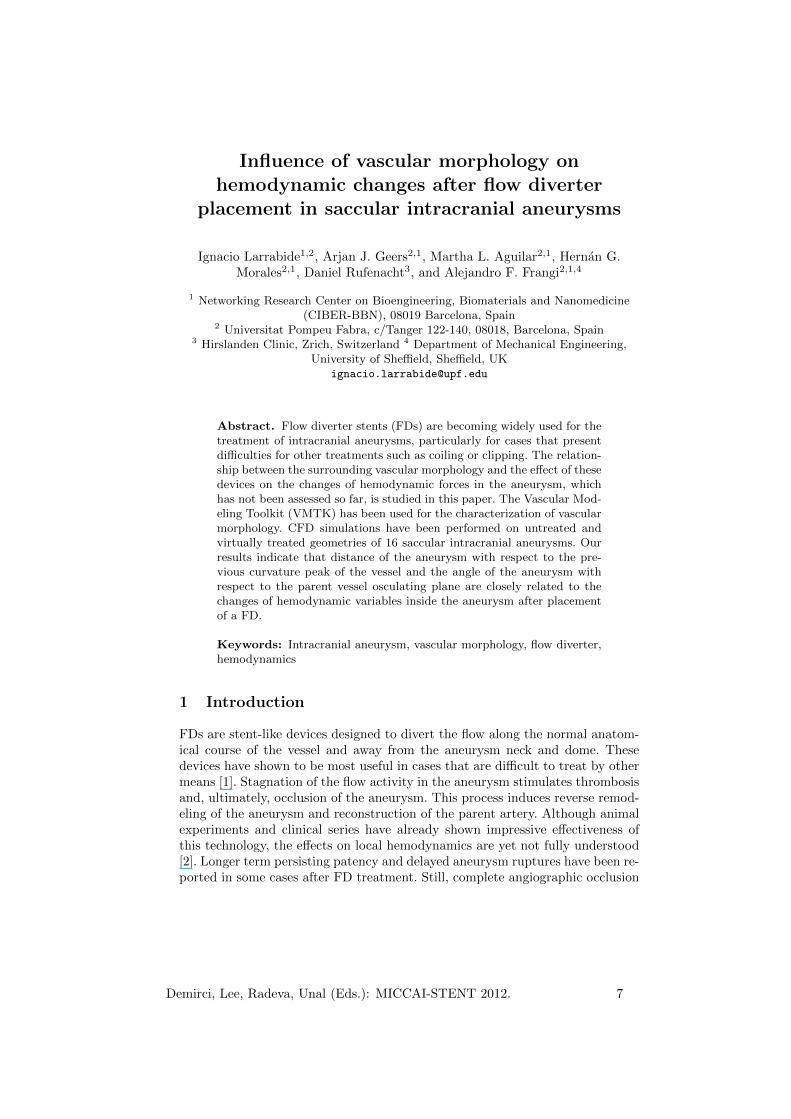
Fig. 2. Changes of hemodynamic variables measured on the aneurysm region.
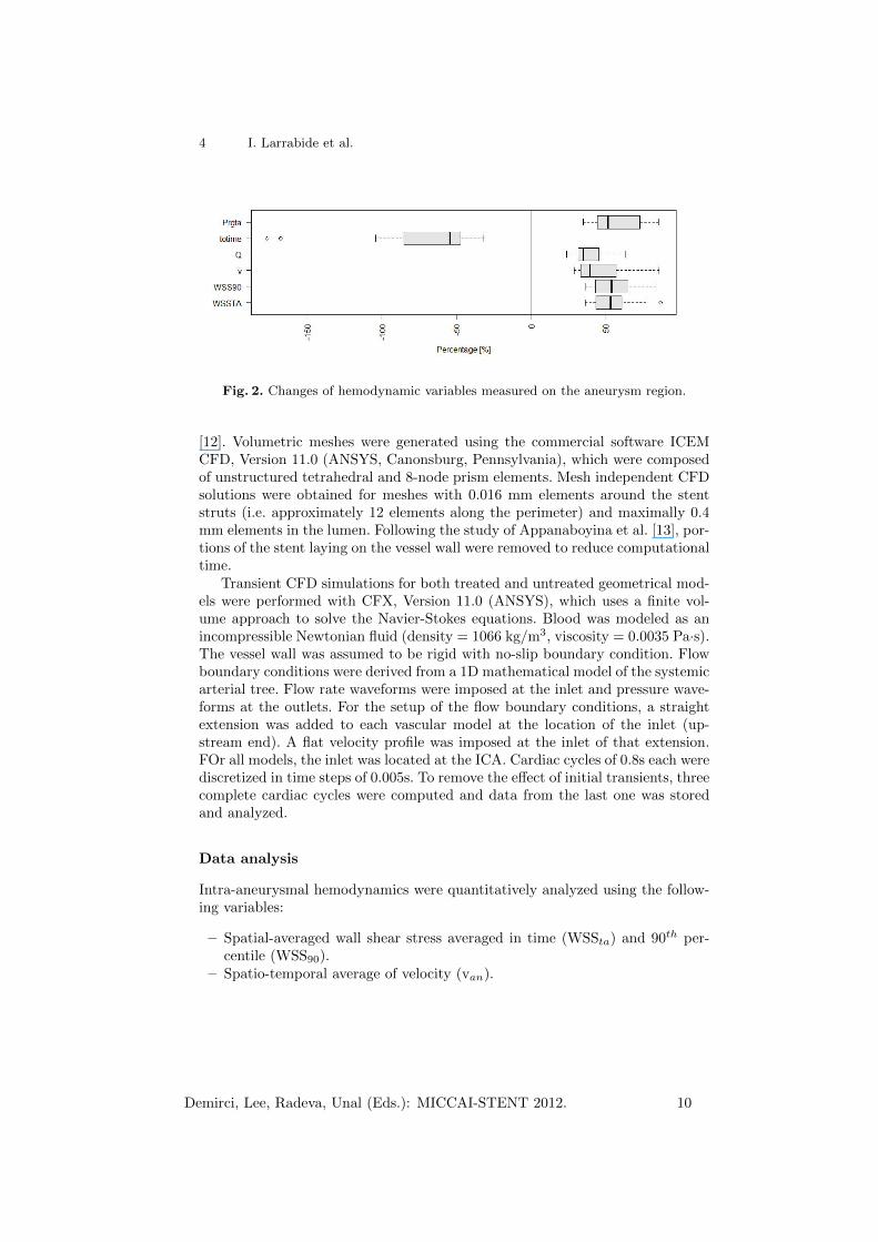
[12]. Volumetric meshes were generated using the commercial software ICEMCFD, Version 11.0 (ANSYS, Canonsburg, Pennsylvania), which were composedof unstructured tetrahedral and 8-node prism elements. Mesh independent CFDsolutions were obtained for meshes with 0.016 mm elements around the stentstruts (i.e. approximately 12 elements along the perimeter) and maximally 0.4mm elements in the lumen. Following the study of Appanaboyina et al. [13], por-tions of the stent laying on the vessel wall were removed to reduce computationaltime.
Transient CFD simulations for both treated and untreated geometrical mod-els were performed with CFX, Version 11.0 (ANSYS), which uses a finite vol-ume approach to solve the Navier-Stokes equations. Blood was modeled as anincompressible Newtonian fluid (density = 1066 kg/m3, viscosity = 0.0035 Pa·s).The vessel wall was assumed to be rigid with no-slip boundary condition. Flowboundary conditions were derived from a 1D mathematical model of the systemicarterial tree. Flow rate waveforms were imposed at the inlet and pressure wave-forms at the outlets. For the setup of the flow boundary conditions, a straightextension was added to each vascular model at the location of the inlet (up-stream end). A flat velocity profile was imposed at the inlet of that extension.FOr all models, the inlet was located at the ICA. Cardiac cycles of 0.8s each werediscretized in time steps of 0.005s. To remove the effect of initial transients, threecomplete cardiac cycles were computed and data from the last one was storedand analyzed.
Data analysis
Intra-aneurysmal hemodynamics were quantitatively analyzed using the follow-ing variables:
– Spatial-averaged wall shear stress averaged in time (WSSta) and 90th per-centile (WSS90).
– Spatio-temporal average of velocity (van).
Demirci, Lee, Radeva, Unal (Eds.): MICCAI-STENT 2012. 10

Assessment of vascular morphology effect on aneurysm treatment 5
– Average aneurysm inflow (Qan).– Turn-over time inside the aneurysm (defined as totime = Van/Qan, with Van
being the aneurysm volume).– Time-average of the aneurysm pressure range (prgta), defined as the differ-
ence between the highest and lowest pressure (in mmHg) in the aneurysmat each time point averaged over time.
These variables were recorded before and after virtual placement of the FD. Thechanges of each variable x was computed as:
xchanges = 100% ∗ (xuntreated − xtreated)/xuntreated (1)
A negative change indicates an effective increase of the variable and a decreaseotherwise. Data analysis was performed using the R statistical package software[14]. Spearman’s test was used to study correlation between the morphologi-cal variables and hemodynamics reduction. Results were considered statisticallysignificant for p<0.05.
3 Results
lS [mm] Dpc[mm] ao[degrees]
mean (SD) 49.98 (16.78) -8.39 (5.19) 92.77 (32.83)min 29.76 -18.50 49.60max 86.49 -2.56 144.23
Table 1. Vascular morphological descriptors for the cases studied
Table 1 summarizes the morphological variables in terms of mean, standarddeviation (SD), minimum and maximum values. The lS went from 26.76 to86.49mm and the average Dpc was 8.39mm (SD = 5.19mm). The average anglebetween the aneurysm and the osculating plane of the parent vessel at thatlocation was 92.77 degrees (SD = 32.83). After FD deployment, a mean porosityof 72.8% (SD = 5.4%) was measured in all our cases.
Fig. 2 presents boxplots of the reduction in hemodynamic variables. All vari-ables have been reduced after the placement of the FD with the exception oftotime that consistently increased after FD placement, which renders as a neg-ative reduction (Fig. 2). Changes in hemodynamic variables were statisticallysignificant.
Fig. 3 presents scatter plots relating the hemodynamic and morphologicalvariables. Regarding Dpc, significant correlation was found for WSSta (ρ = -0.53). Although not statistically significant, high correlation was found for Qan
(ρ = -0.47, p= 0.06) and totime (ρ = 0.41, p= 0.06). For WSS90, van and prgta nosignificant correlation was found. This findings suggest that, the further away theaneurysm is located from the curvature peak, the higher the FD induced changes
Demirci, Lee, Radeva, Unal (Eds.): MICCAI-STENT 2012. 11
6 I. Larrabide et al.
in inflow and WSS. One possible explanation is that the further downstream weare from curvature peaks, secondary flow disappears, main flow is re-stabilizedand oriented in the vessel longitudinal direction. In this condition, the FD mighthave a stronger influence on hemodynamic variables.
Fig. 4(a) presents the hemodynamic results for two cases that illustrate thisdifference. For the aneurysm far from the curvature peak, the flow into theaneurysm is largely reduced. For the aneurysm near the curvature peak, a strongvortex generated at that location progresses into the aneurysm creating a majorflow stream into it. After placement of the FD, the first case presents a strongercessation of flow motion inside the aneurysm. On the other hand, the inflow inthe aneurysm near the curvature peak is not strongly affected by the presenceof the FD.
When looking at ao, significant correlations are observed for WSSta (ρ =0.58), WSS90 (ρ = 0.64), van (ρ = 0.58) and prgta (ρ = 0.65). No significantcorrelation was found for Qan (ρ= 0.26) and totime (ρ= -0.26). It was found thatas the aneurysm angle is leaning towards the outer side of the bend (ao > 90◦),the relative reduction of hemodynamic variables is larger. In such geometricalcondition, the changes induced by the presence of a FD have a stronger effecton hemodynamic changes is higher. Fig. 4(b) presents hemodynamic results fortwo exemplary cases, one where the aneurysm between the aneurysm and theosculating plane is wide (top) and another with a narrow angle (bottom). Weobserve for the case on the top (wide angle) that the part of the main flow jetgoing into the aneurysm is small and the presence of a FD redirects the flowto the parent vessel. When the angle between the aneurysm and the osculatingplane is narrow (bottom) the presence of the FD induces smaller changes in thelocal flow.
In the present work, we make use and extend previous work by Piccinelli etal. [8] by looking at the effect of FDs in relation to vascular morphology. In thisway, we provide a link which has not been assessed before. Still, further work isrequired to set the basis for such studies and their future use in clinical practice.
One limitation of this work is that is only based on simulation results andnot on experimental or clinical observations. Nevertheless, special care has beenput on the extraction of the anatomical models to ensure their fidelity ( byusing state-of-the-art image analysis techniques) and on the boundary conditionschosen (ensuring realistic flow conditions in all models). In this way, we expectthat the results reported by the models are, at least, within physiological ranges.
4 Conclusions
In this study we investigated the effect vascular morphology on hemodynamicsafter FD. CFD simulations were performed before and after virtual placementof the FD. We found that time-averaged WSS is more reduced in aneurysmsfar away from the curvature peak. This larger reduction is attributed to thatsecondary flow is reduced further downstream from the curvature peak. Thisis reflected by the high correlation observed between Dpc and Qan. We also
Demirci, Lee, Radeva, Unal (Eds.): MICCAI-STENT 2012. 12
Assessment of vascular morphology effect on aneurysm treatment 7
observed high correlations with statistical significance for reduction of WSS,velocity and pressure range in the aneurysm with respect to the angle betweenthe local osculating plane and the aneurysm. Local hemodynamics are largelyaffected by the incidence angle of the aneurysm, which strongly influences thedirection the aneurysm inflow jet angle.
The hemodynamic variable reduction can be correlated to vascular morphol-ogy nearby the aneurysm. Still, to provide proper predictive estimations of flowin complex vascular geometries, a deeper understanding of the relationship be-tween geometry and hemodynamics is fundamental.
Acknowledgements
This research has been partially funded by the Industrial and Technological De-velopment Center(CDTI) under the CENIT-CDTEAM and CENIT-cvREMODprograms, the European Commissions project @neurIST (IST-2005-027703) andPhilips Healthcare (Best, The Netherlands), and from the Catalonian Depart-ment of Innovation, Universities and Enterprise (DIUE), through the EndoTreatproject (exp. VALOR2010-00064).
References
1. Nelson, P.K., Lylyk, P., Szikora, I., Wetzel, S.G., Wanke, I., Fiorella, D.: Thepipeline embolization device for the intracranial treatment of aneurysms trial.AJNR. American journal of neuroradiology 32(1) (January 2011) 34–40
2. Sadasivan, C., Lieber, B.B., Gounis, M.J., Lopes, D.K., Hopkins, L.N.: Angio-graphic quantification of contrast medium washout from cerebral aneurysms afterstent placement. AJNR. American journal of neuroradiology 23(7) (August 2002)1214–21
3. Cebral, J.R., Mut, F., Raschi, M., Scrivano, E., Ceratto, R., Lylyk, P., Putman,C.M.: Aneurysm Rupture Following Treatment with Flow-Diverting Stents: Com-putational Hemodynamics Analysis of Treatment. AJNR. American journal ofneuroradiology (November 2010) 1–7
4. Kulcsar, Z., Houdart, E., Bonafe, A., Parker, G., Millar, J., Goddard, a.J.P.,Renowden, S., Gal, G., Turowski, B., Mitchell, K., Gray, F., Rodriguez, M.,van den Berg, R., Gruber, A., Desal, H., Wanke, I., Rufenacht, D.a.: Intra-Aneurysmal Thrombosis as a Possible Cause of Delayed Aneurysm Rupture af-ter Flow-Diversion Treatment. AJNR. American journal of neuroradiology 23(1)(November 2010) 20–25
5. Klisch, J., Turk, a., Turner, R., Woo, H.H., Fiorella, D.: Very late thrombosis offlow-diverting constructs after the treatment of large fusiform posterior circulationaneurysms. AJNR. American journal of neuroradiology 32(4) (April 2011) 627–32
6. Lieber, B.B., Sadasivan, C.: Endoluminal scaffolds for vascular reconstruction andexclusion of aneurysms from the cerebral circulation. Stroke; a journal of cerebralcirculation 41(10 Suppl) (October 2010) S21–5
7. Sadasivan, C., Cesar, L., Seong, J., Wakhloo, A.K., Lieber, B.B.: Treatment ofrabbit elastase-induced aneurysm models by flow diverters: development of quan-tifiable indexes of device performance using digital subtraction angiography. IEEEtransactions on medical imaging 28(7) (July 2009) 1117–25
Demirci, Lee, Radeva, Unal (Eds.): MICCAI-STENT 2012. 13

8 I. Larrabide et al.
8. Piccinelli, M., Bacigaluppi, S., Boccardi, E., Ene-Iordache, B., Remuzzi, A.,Veneziani, A., Antiga, L.: Geometry of the internal carotid artery and recur-rent patterns in location, orientation and rupture status of lateral aneurysms: animage-based computational study. Neurosurgery 68(5) (January 2011) 1270–1285
9. Piccinelli, M., Veneziani, A., Steinman, D.a., Remuzzi, A., Antiga, L.: A frameworkfor geometric analysis of vascular structures: application to cerebral aneurysms.IEEE transactions on medical imaging 28(8) (August 2009) 1141–55
10. Hernandez, M., Frangi, A.F.: Non-parametric geodesic active regions: method andevaluation for cerebral aneurysms segmentation in 3DRA and CTA. Medical imageanalysis 11(3) (June 2007) 224–41
11. Larrabide, I., Omedas, P., Martelli, Y., Planes, X., Nieber, M., Moya, J.A., Bu-takoff, C., Sebastian, R., Camara, O., de Craene, M., Bijnens, B.H., Frangi, A.F.:GIMIAS: An open source framework for efficient development of research toolsand clinical prototypes. In: Functional Imaging and Modeling of the Heart. Vol-ume 5528/2009 of Lecture Notes in Computer Science. (2009) 417–426
12. Larrabide, I., Kim, M., Augsburger, L., Villa-Uriol, M.C., Rufenacht, D., Frangi,A.F.: Fast virtual deployment of self-expandable stents: Method and in vitro eval-uation for intracranial aneurysmal stenting. Medical image analysis (May 2010)
13. Appanaboyina, S., Mut, F., Lohner, R., Putman, C., Cebral, J.: Simulation ofintracranial aneurysm stenting: Techniques and challenges. Computer Methods inApplied Mechanics and Engineering 198(45-46) (2009) 3567–3582
14. Team, R.D.C.: R: A Language and Environment for Statistical Computing (2008)
Demirci, Lee, Radeva, Unal (Eds.): MICCAI-STENT 2012. 14

Assessment of vascular morphology effect on aneurysm treatment 9
●
●
●
●●
●
●
●
●
●
●
●●
●●
●
●
●
●
●
●
●
●
−15 −10 −5
4050
6070
80
Dpc [mm]
WSS
ta [P
a]
* p = 0.005 rho = −0.577
●
●
●
●●
●
●
●
●●●
●●
●
●
●
●
●
●
●
●
●●
−15 −10 −5
4050
6070
80Dpc [mm]
WSS
90 [P
a]
p = 0.013 rho = −0.515
●
●
●
●
●
●
●
●
●
●
●
●
●
●
●
●
●
●
●
●
●
●
●
−15 −10 −5
3050
70
Dpc [mm]
v ta [m
ms]
p = 0.037 rho = −0.44
●
●
●
●
●
●
●
●
●
●
●
●
●
●
●
●
●
●●
●
●●
●
−15 −10 −5
3040
5060
Dpc [mm]
Qan
[cm
3s]
p = 0.102 rho = −0.35
●
●
●
●
●
●
●
●
●
●
●
●●
●●
●
●●
●
●
●●
●
−15 −10 −5
−150
−100
−50
Dpc [mm]
totim
e [s
]
p = 0.1 rho = 0.352
●
●●
●
●
●
●
●
●
● ●
●
●
●●
●
●●
●
●
●●
●
−15 −10 −5
4050
6070
80Dpc [mm]
p rgt
a [m
mH
g]
p = 0.149 rho = −0.31
●
●
●
●●
●
●
●
●
●
●
●●
●●
●
●
●
●
●
●
●
●
60 80 100 140
4050
6070
80
αo [degrees]
WSS
ta [P
a]
* p = 0.011 rho = 0.528
●
●
●
●●
●
●
●
● ●●
●●
●
●
●
●
●
●
●
●
●●
60 80 100 140
4050
6070
80
αo [degrees]
WSS
90 [P
a]
* p = 0.005 rho = 0.578
●
●
●
●
●
●
●
●
●
●
●
●
●
●
●
●
●
●
●
●
●
●
●
60 80 100 140
3050
70
αo [degrees]
v ta [m
ms]
* p = 0.023 rho = 0.474
●
●
●
●
●
●
●
●
●
●
●
●
●
●
●
●
●
●●
●
●●
●
60 80 100 140
3040
5060
αo [degrees]
Qan
[cm
3s]
p = 0.171 rho = 0.295
●
●
●
●
●
●
●
●
●
●
●
●●
●●
●
●●
●
●
●●
●
60 80 100 140
−150
−100
−50
αo [degrees]
totim
e [s
]
p = 0.186 rho = −0.286
●
●●
●
●
●
●
●
●
●●
●
●
●●
●
●●
●
●
●●
●
60 80 100 140
4050
6070
80
αo [degrees]
p rgt
a [m
mH
g]
* p = 0.037 rho = 0.44
Fig. 3. Scatter plots for the relation between morphological and hemodynamic variablesstudied. Also, locally-weighted polynomial (blue) regression is shown for each plot.
Demirci, Lee, Radeva, Unal (Eds.): MICCAI-STENT 2012. 15

10 I. Larrabide et al.
Dpc ao
Far
Near
Wid
eN
arr
ow
Untreated Treated Untreated Treated
(a) (b)
Fig. 4. Qualitative hemodynamic simulations results for four selected cases are pre-sented. Each group of images presents streamlines (top), velocity magnitude on a crosssection plane across the aneurysm (bottom), untreated (left) and treated (right). (a)Two cases with extreme values of Dpc and on the right two extreme cases for ao. Onthe left, the one on the top is an aneurysm laying far from the curvature peak (highDpc) and on the one the bottom is very near to the peak (low Dpc). (b) The one ontop presents a wide angle with respect to the osculating plane (high ao) and the oneon the bottom has a narrow angle with respect to it (low ao).
Demirci, Lee, Radeva, Unal (Eds.): MICCAI-STENT 2012. 16