Helical and Helical-Bevel Gear Units X / Operating Instructions ...
3368 IEEE TRANSACTIONS ON MAGNETICS, VOL. 40, NO. 5, SEPTEMBER 2004
Influence of AC Magnetic Field Amplitude on theSurface Magnetoimpedance Tensor in Amorphous
Wire With Helical Magnetic AnisotropyA. P. Chen, M. R. Britel, V. Zhukova, A. Zhukov, L. Dominguez, A. B. Chizhik, J. M. Blanco, and Julián González
Abstract—We have performed experimental and theoreticalstudies on the influence of ac magnetic field amplitude on the mag-netoimpedance tensor in an amorphous wire with helical magneticanisotropy. For the experimental measurements, we used an amor-phous wire of composition (Co0 94Fe0 06)72 5Si12 5B15 withnegative, nearly zero magnetostriction constant, excited either byan ac circular or by an axial magnetic field created by anac electric current. We changed the ac current amplitude from7.5 to 40 mA and the current frequency from 1.5 to 20 MHz.The values of the asymmetric giant magnetoimpedance ratioassociated with the sweeping direction of the dc field ex and thecorresponding sensitivity were 211% and 0.64 V/Oe, respectively,for an ac current of 37.5 mA at 3 MHz. For the theoretical studybased on the magnetization rotation, we obtained the second-orderharmonic of the ac magnetization (2) induced by the relativelyhigh ac magnetic field by solving the Landau–Lifshitz–Gilbert(LLG) equation. We also considered a second-order surfaceimpedance tensor ^(2), which allowed us to analyze quantitativelythe influence of the ac magnetic field amplitude on the impedancetensor of the wire. We obtained the domain model of the wirewith helical magnetic anisotropy having multidomains and themagnetization vector 0 directed in the easy direction, andthe corresponding static magnetic configurations, by solving thestatic LLG equation. For the given magnetic configurations, wecalculated the second-order impedance tensor ^(2). The resultscan well explain the irregular field characteristics of the voltageresponses at low dc field value, when the wire was excited at highfrequency and at large ac magnetic field.
Index Terms—Impedance tensor, induced anisotropy, magne-toimpedance effect.
I. INTRODUCTION
G IANT MAGNETOIMPEDANCE (GMI) effect in amor-phous and polycrystalline ferromagnetic materials has
been intensively studied during the past decade owing to theirexciting technological applications in developing new-gen-eration magnetic sensors of high performance [1]–[10]. TheGMI effect in amorphous wire deals with a large and sensitive
Manuscript received August 28, 2003; revised June 4, 2004.A. P. Chen, M. R. Britel, A. Zhukov, A. B. Chizhik, and J. González are
with the Department of Material Physics, Chemistry Faculty, Universidad delPais Vasco (UPV), 20080 San Sebastián, Spain (e-mail: [email protected];[email protected]; [email protected]; [email protected]; [email protected]).
V. Zhukova is with the Instituto de Ciencias de Materiales, CSIC, Canto-blanco, 28049 Madrid, Spain, and also with “TAMag Iberica” S.L., Parque Tec-nológico de Miramón, 20009 San Sebastián, Spain.
L. Dominguez and J. M. Blanco are with the Department of Applied Physics I,EUPDS, UPV/EHU, San Sebastián 20018, Spain (e-mail: [email protected];[email protected]).
Digital Object Identifier 10.1109/TMAG.2004.833433
change of the voltage response induced between the wireends, or in a pickup coil wound on the wire on a dc externalmagnetic field [1]–[10]. Using the asymptotic-series-ex-pansion method of solving Maxwell equations for a wire,and considering the ac permeability tensor associated withmagnetization rotation, the linear voltage responses can bedescribed by an impedance tensor, . In this way, it has beenpossible to develop a rigorous quantitative analysis of the MIcharacteristics in wires excited by an ac electric current or/andac axial magnetic field, as depending on the longitudinal dc biasmagnetic field. The theory agrees quite well with numericalexperimental data at relatively low ac magnetic field created byan ac electric current of small amplitude [9], [10].
On the other hand, in relation to the ac magnetization process,the ac current amplitude becomes an important parameter inGMI effect. It has been observed that the MI effect could beenhanced by selecting the adequate ac current amplitude at thefrequency range from 100 kHz to 1 MHz in amorphous wiresof various compositions [11], [12]. It has been reported thatby increasing the ac current amplitude from 2.5 to 25 mA, theGMI profiles display an evolution from double peaks to singlepeak in thermally treated Co-based conventional wire at currentfrequencies 100 kHz [13]. At higher ac current amplitude than25 mA, the voltage response becomes nonlinear (nonsinu-soidal); when the amplitude exceeds some threshold value,the circular coercivity field would be overcome associatedto a Barkhausen jump in the circular magnetization process[14]–[19]. In this case, it has been detected that the secondharmonic of [17] and the even harmonics of [16], [18],[19] are strongly dependent on the axial dc magnetic field. Itcan be noted that extremely high sensitivity of the MI effectcould be found by studying higher harmonics of the voltagesignal of the GMI element [16]–[19].
The present paper deals with the experimental and theoreticalstudy of the voltage responses and in amorphous wirespresenting helical magnetic anisotropy, excited by an ac circular
, or axial , magnetic field at high frequency and high am-plitude. The paper is organized as follows. Section II presentsthe experimental scheme and the measuring results. Section IIIdeals with the magnetization rotation, the second order of the acmagnetization , and the static magnetic structures of twodomains with opposite sign of the magnetization vector ,obtained by solving the Landau–Lifshitz–Gilbert equation. Fol-lowing Faraday’s law, the voltage responses and havebeen calculated and expressed in terms of the surface impedancetensor . It is demonstrated that the field behavior of the second
0018-9464/04$20.00 © 2004 IEEE
CHEN et al.: INFLUENCE OF AC MAGNETIC FIELD AMPLITUDE ON THE SURFACE MI TENSOR 3369
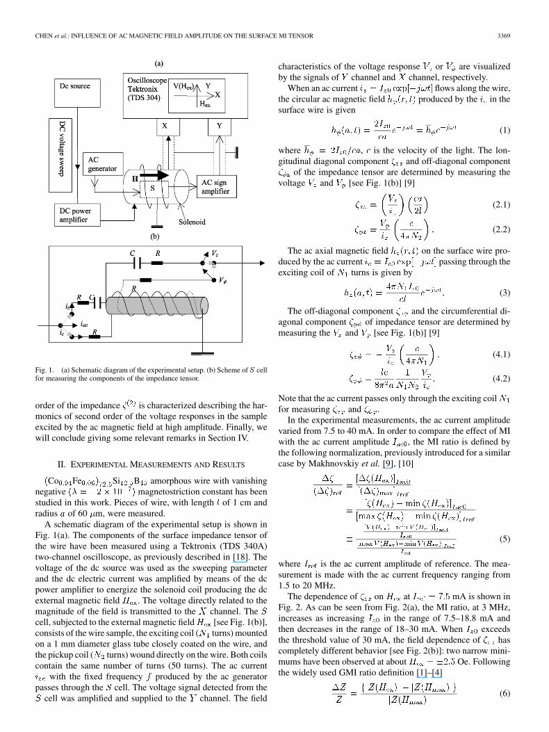
Fig. 1. (a) Schematic diagram of the experimental setup. (b) Scheme of S cellfor measuring the components of the impedance tensor.
order of the impedance is characterized describing the har-monics of second order of the voltage responses in the sampleexcited by the ac magnetic field at high amplitude. Finally, wewill conclude giving some relevant remarks in Section IV.
II. EXPERIMENTAL MEASUREMENTS AND RESULTS
Co Fe Si B amorphous wire with vanishingnegative magnetostriction constant has beenstudied in this work. Pieces of wire, with length of 1 cm andradius of 60 m, were measured.
A schematic diagram of the experimental setup is shown inFig. 1(a). The components of the surface impedance tensor ofthe wire have been measured using a Tektronix (TDS 340A)two-channel oscilloscope, as previously described in [18]. Thevoltage of the dc source was used as the sweeping parameterand the dc electric current was amplified by means of the dcpower amplifier to energize the solenoid coil producing the dcexternal magnetic field . The voltage directly related to themagnitude of the field is transmitted to the channel. Thecell, subjected to the external magnetic field [see Fig. 1(b)],consists of the wire sample, the exciting coil ( turns) mountedon a 1 mm diameter glass tube closely coated on the wire, andthe pickup coil ( turns) wound directly on the wire. Both coilscontain the same number of turns (50 turns). The ac current
with the fixed frequency produced by the ac generatorpasses through the cell. The voltage signal detected from the
cell was amplified and supplied to the channel. The field
characteristics of the voltage response or are visualizedby the signals of channel and channel, respectively.
When an ac current flows along the wire,the circular ac magnetic field produced by the in thesurface wire is given
(1)
where , is the velocity of the light. The lon-gitudinal diagonal component and off-diagonal component
of the impedance tensor are determined by measuring thevoltage and [see Fig. 1(b)] [9]
(2.1)
(2.2)
The ac axial magnetic field on the surface wire pro-duced by the ac current passing through theexciting coil of turns is given by
(3)
The off-diagonal component and the circumferential di-agonal component of impedance tensor are determined bymeasuring the and [see Fig. 1(b)] [9]
(4.1)
(4.2)
Note that the ac current passes only through the exciting coilfor measuring and .
In the experimental measurements, the ac current amplitudevaried from 7.5 to 40 mA. In order to compare the effect of MIwith the ac current amplitude , the MI ratio is defined bythe following normalization, previously introduced for a similarcase by Makhnovskiy et al. [9], [10]
(5)
where is the ac current amplitude of reference. The mea-surement is made with the ac current frequency ranging from1.5 to 20 MHz.
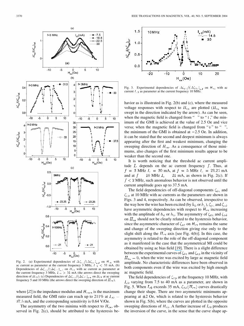
The dependence of on at mA is shown inFig. 2. As can be seen from Fig. 2(a), the MI ratio, at 3 MHz,increases as increasing in the range of 7.5–18.8 mA andthen decreases in the range of 18–30 mA. When exceedsthe threshold value of 30 mA, the field dependence of hascompletely different behavior [see Fig. 2(b)]: two narrow mini-mums have been observed at about Oe. Followingthe widely used GMI ratio definition [1]–[4]
(6)
3370 IEEE TRANSACTIONS ON MAGNETICS, VOL. 40, NO. 5, SEPTEMBER 2004
Fig. 2. (a) Experimental dependencies of �� =(�� ) on H withac current as parameter at the current frequency 3 MHz, I < 31 mA. (b)Dependencies of �� =(�� ) on H with ac current as parameter atthe current frequency 3 MHz, I > 31 mA (the arrows direct the sweepingdirection of H ). (c) Dependencies of �� =(�� ) on H at ac currentfrequency 5 and 10 MHz (the arrows direct the sweeping direction of H ).
where is the impedance modulus and is the maximummeasured field, the GMI ratio can reach up to 211% at
mA, and the corresponding sensitivity is 0.64 V/Oe.The asymmetry of the two minima with respect to , ob-
served in Fig. 2(c), should be attributed to the hysteresis be-
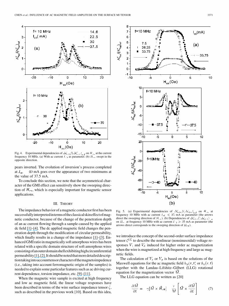
Fig. 3. Experimental dependencies of �� =(�� ) on H with accurrent I as parameter at the current frequency 10 MHz.
havior as is illustrated in Fig. 2(b) and (c), where the measuredvoltage responses with respect to are plotted ( wasswept in the direction indicated by the arrow). As can be seen,when the magnetic field is changed from “ ” to “ ,” the min-imum of the GMI is achieved at the value of 2.5 Oe and viceversa; when the magnetic field is changed from “ ” to “ ”,the minimum of the GMI is obtained at 2.5 Oe. In addition,it can be stated that the second and deepest minimum is alwaysappearing after the first and weakest minimum, changing thesweeping direction of . As a consequence of those mini-mums, also changes of the first minimum results appear to beweaker than the second one.
It is worth noticing that the threshold ac current ampli-tude depends on the ac current frequency . Thus, at
MHz mA, at MHz mAand at MHz mA, as shown in Fig. 2(c). If
MHz, such anomalous behavior is not observed until thecurrent amplitude goes up to 37.5 mA.
The field dependencies of off-diagonal components andat 10 MHz with ac currents as the parameters are shown in
Figs. 3 and 4, respectively. As can be observed, irrespective tothe way how the wire has been excited (by or ), andhave asymmetric dependencies with respect to increasingwith the amplitude of or . The asymmetry of andon should not be clearly related to the hysteresis behavior,since the asymmetric character of on remains the sameand change of the sweeping direction giving rise only to theslight shift along the axis [see Fig. 4(b)]. In this case, theasymmetry is related to the role of the off-diagonal componentas it manifested in the case that the asymmetrical MI could beobtained by using ac bias field [19]. There is a slight differencebetween the experimental curves of and in the vicinity of
, when the wire was excited by large ac magnetic fieldamplitude. No characteristic differences have been observed inboth components even if the wire was excited by high enoughac magnetic field.
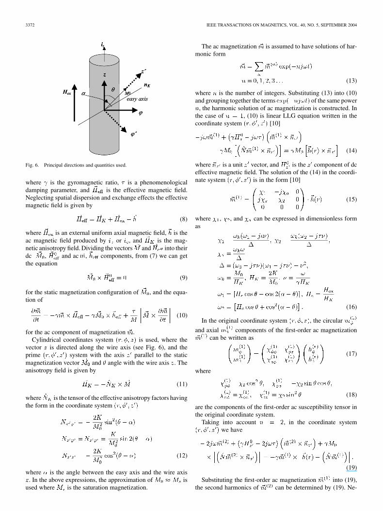
The field dependencies of at the frequency 10 MHz, withvarying from 7.5 to 40 mA as a parameter, are shown in
Fig. 5. When exceeds 35 mA, curves drasticallychange their shape. There are two asymmetric minimums ap-pearing at 2 Oe, which is related to the hysteresis behaviorshown in Fig. 5(b), where the curves are plotted in the oppositesweeping directions of . A further increase of producesthe inversion of the curve, in the sense that the curve shape ap-
CHEN et al.: INFLUENCE OF AC MAGNETIC FIELD AMPLITUDE ON THE SURFACE MI TENSOR 3371
Fig. 4. Experimental dependencies of�� =(�� ) onH at the currentfrequency 10 MHz. (a) With ac current I as parameter. (b) H swept in theopposite direction.
pears inverted. The evolution of inversion’s process completedat mA goes over the appearance of two minimums atthe value of 37.5 mA.
To conclude this section, we note that the asymmetrical char-acter of the GMI effect can sensitively show the sweeping direc-tion of , which is especially important for magnetic sensorapplications.
III. THEORY
The impedancebehavior of a magnetic conductor first has beensuccessfullyinterpretedintermsoftheclassicalskineffectofmag-netic conductor, because of the change of the penetration depthof an ac current flowing through a sample caused by the applieddc field [1]–[4]. The dc applied magnetic field changes the pen-etration depth through the modification of circular permeability,which finally results in a change of the impedance [1]–[3]. En-hanced GMI ratio in magnetically soft amorphous wires has beenrelated with a specific domain structure of soft amorphous wiresconsistingofanouterdomainshellexhibitinghighcircumferentialpermeability[1],[2].Itshouldbenotedthatmoredetaileddescrip-tiontakingintoaccounttensorcharacterofthemagnetoimpedence(i.e., taking into account ferromagnetic origin of the samples) isneeded to explain some particular features such as ac driving cur-rent dependence, torsion impedance, etc. [9]–[11].
When the magnetic wire sample is excited at high frequencyand low ac magnetic field, the linear voltage responses havebeen described in terms of the wire surface impedance tensor ,such as described in the previous work [10]. Based on this idea,
Fig. 5. (a) Experimental dependencies of �� =(�� ) on H atfrequency 10 MHz with ac current I < 35 mA as parameter (the arrowsdirect the sweeping direction of H ). (b) Dependencies of �� =(�� )on H at frequency 10 MHz with ac current I > 35 mA as parameter (thearrows direct corresponds to the sweeping direction of H ).
we introduce the concept of the second-order surface impedancetensor to describe the nonlinear (nonsinusoidal) voltage re-sponses and induced for higher order ac magnetizationwhen the wire is magnetized at high frequency and large ac mag-netic fields.
The calculation of or is based on the solutions of theMaxwell equations for the ac magnetic field ortogether with the Landau–Lifshitz–Gilbert (LLG) rotationalequation for the magnetization vector .
The LLG equation can be written as [20]
(7)
3372 IEEE TRANSACTIONS ON MAGNETICS, VOL. 40, NO. 5, SEPTEMBER 2004
Fig. 6. Principal directions and quantities used.
where is the gyromagnetic ratio, is a phenomenologicaldamping parameter, and is the effective magnetic field.Neglecting spatial dispersion and exchange effects the effectivemagnetic field is given by
(8)
where is an external uniform axial magnetic field, is theac magnetic field produced by or , and is the mag-netic anisotropy field. Dividing the vectors and into theirdc , and ac , components, from (7) we can getthe equation
(9)
for the static magnetization configuration of , and the equa-tion of
(10)
for the ac component of magnetization .Cylindrical coordinates system is used, where the
vector is directed along the wire axis (see Fig. 6), and theprime system with the axis parallel to the staticmagnetization vector and angle with the wire axis . Theanisotropy field is given by
(11)
where is the tensor of the effective anisotropy factors havingthe form in the coordinate system
(12)
where is the angle between the easy axis and the wire axis. In the above expressions, the approximation of is
used where is the saturation magnetization.
The ac magnetization is assumed to have solutions of har-monic form
(13)
where is the number of integers. Substituting (13) into (10)and grouping together the terms of the same power
, the harmonic solution of ac magnetization is constructed. Inthe case of , (10) is linear LLG equation written in thecoordinate system [10]
(14)
where is a unit vector, and is the component of dceffective magnetic field. The solution of the (14) in the coordi-nate system is in the form [10]
(15)
where , , and can be expressed in dimensionless formas
(16)
In the original coordinate system , the circular
and axial components of the first-order ac magnetizationcan be written as
(17)
where
(18)
are the components of the first-order ac susceptibility tensor inthe original coordinate system.
Taking into account , in the coordinate systemwe have
(19)
Substituting the first-order ac magnetization into (19),the second harmonics of can be determined by (19). Ne-
CHEN et al.: INFLUENCE OF AC MAGNETIC FIELD AMPLITUDE ON THE SURFACE MI TENSOR 3373
glecting the second-order radial component [10], [16] andusing the rotating conversional matrix, the second harmoniccomponents of can be converted to the original coordinatesystem as
(20)
where
(21)
are the components of the second-order ac susceptibility deter-mined by the first order ac susceptibility , and the anglefunction ,
(22)
It is worth noting that the second-order ac susceptibilitytensor is strongly dependent on the magnetic configura-tion. In the case of the wire sample having a circular anisotropy,
leads to .The field dependence of the static magnetic configuration
can be determined from (10), which indicates that inthe coordinate system , the component of the dc ef-fective magnetic field must be zero
(23)
Following (23), at the angle that determines thedirection of with respect to the wire axis must satisfy thecondition
(24)
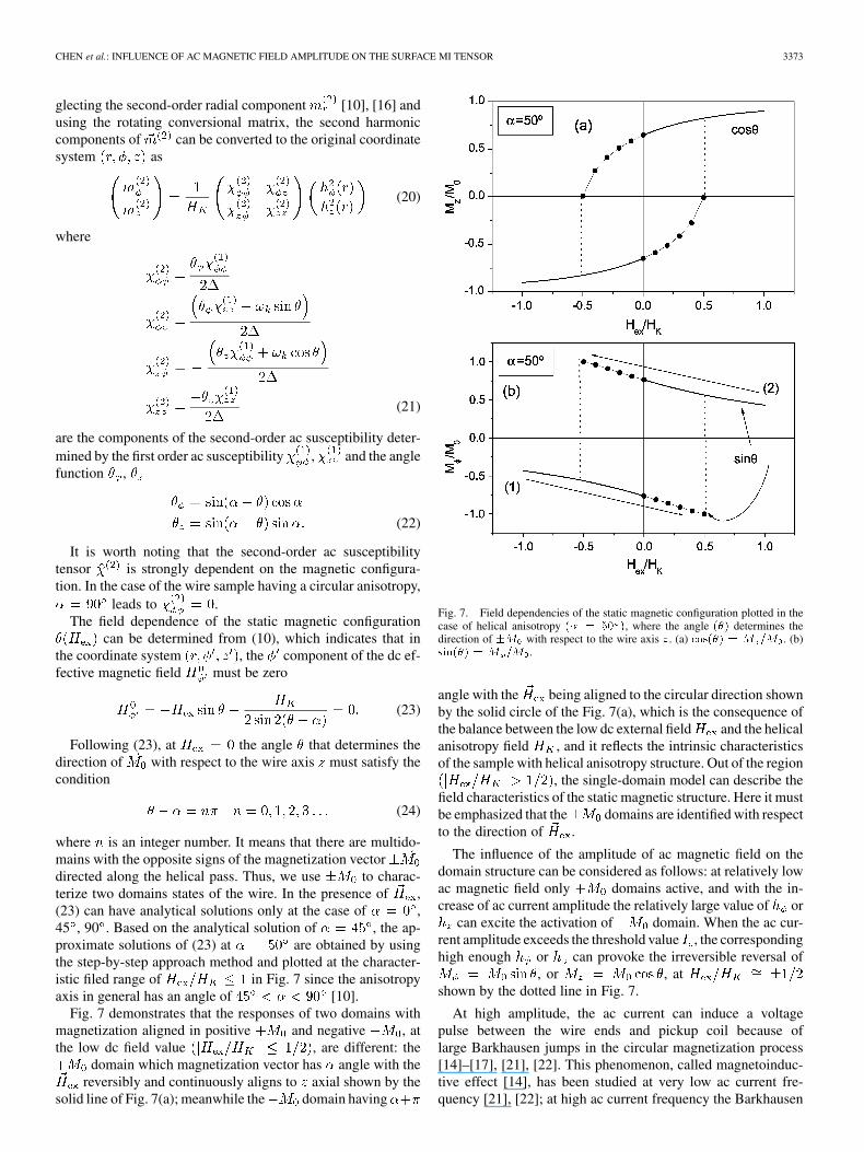
where is an integer number. It means that there are multido-mains with the opposite signs of the magnetization vectordirected along the helical pass. Thus, we use to charac-terize two domains states of the wire. In the presence of ,(23) can have analytical solutions only at the case of ,45 , 90 . Based on the analytical solution of , the ap-proximate solutions of (23) at are obtained by usingthe step-by-step approach method and plotted at the character-istic filed range of in Fig. 7 since the anisotropyaxis in general has an angle of [10].
Fig. 7 demonstrates that the responses of two domains withmagnetization aligned in positive and negative , atthe low dc field value , are different: the
domain which magnetization vector has angle with thereversibly and continuously aligns to axial shown by the
solid line of Fig. 7(a); meanwhile the domain having
Fig. 7. Field dependencies of the static magnetic configuration plotted in thecase of helical anisotropy (� = 50 ), where the angle (�) determines thedirection of �M with respect to the wire axis z. (a) cos(�) = M =M . (b)sin(�) = M =M .
angle with the being aligned to the circular direction shownby the solid circle of the Fig. 7(a), which is the consequence ofthe balance between the low dc external field and the helicalanisotropy field , and it reflects the intrinsic characteristicsof the sample with helical anisotropy structure. Out of the region
, the single-domain model can describe thefield characteristics of the static magnetic structure. Here it mustbe emphasized that the domains are identified with respectto the direction of .
The influence of the amplitude of ac magnetic field on thedomain structure can be considered as follows: at relatively lowac magnetic field only domains active, and with the in-crease of ac current amplitude the relatively large value of or
can excite the activation of domain. When the ac cur-rent amplitude exceeds the threshold value , the correspondinghigh enough or can provoke the irreversible reversal of
, or , atshown by the dotted line in Fig. 7.
At high amplitude, the ac current can induce a voltagepulse between the wire ends and pickup coil because oflarge Barkhausen jumps in the circular magnetization process[14]–[17], [21], [22]. This phenomenon, called magnetoinduc-tive effect [14], has been studied at very low ac current fre-quency [21], [22]; at high ac current frequency the Barkhausen
3374 IEEE TRANSACTIONS ON MAGNETICS, VOL. 40, NO. 5, SEPTEMBER 2004
jump occurs twice at each cycle [16], [24], [25], and, conse-quently, the reversal of the dominates the ac magnetizationprocess.
The threshold value of ac magnetic field can be estimatedby the Stoner–Wolfharth approach [16], [23]
Oe (25)
for Oe, . The corresponding thresholdac current amplitude passing along the wire, as follows from(1), is approximately 34 mA for the conventional wire. The cur-rent flowing along the wire surface is the sum of both the drivencurrent and the inductive current that has the same di-rection of and its value is proportional to the frequency of[26]. As increasing the frequency of , an increase of is ob-served and the need of the value of for achieving the thresholdvalue results to be small than that at the low frequency, whichcan explain the measured data of Fig. 2(c).
Furthermore, Fig. 7(b) indicates that if is changed from“ ” to “ ”, the corresponding curve of denoting 1 has themaximum absolute value of 1, or the achieves the max-imum , at the points of . Vice versa,if is changed from “ ” to “ ,” the curve of denotingas 2 has the maximum absolute value at .This can be also stated as follows: during the sweeping ofin the maximum values with opposed sign, the circular magne-tization has two jumps at the points of . Inaddition, the absolute value of the circular magnetizationat the second jump is always larger than at the first
. This statement later will help us to under-stand the asymmetry of GMI effect with respect to relatedto its sweeping direction.
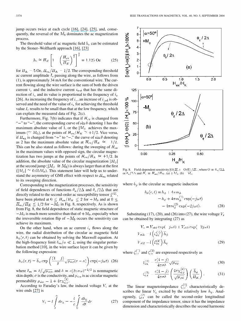
Corresponding to the magnetization processes, the sensitivityof field dependences of functions and that aredirectly related to the second-order ac susceptibility tensor ,have been plotted at for and at
for in Fig. 8, respectively. As is shownfrom Fig. 8, the field dependence of static magnetic structure of
is much more sensitive than that of , especially whenthe irreversible rotation flip of occurs the sensitivity canachieve its maximum.
On the other hand, when an ac current flows along thewire, the radial distribution of the circular ac magnetic field
can be obtained by solving the Maxwell equation. Atthe high-frequency limit , using the singular pertur-bation method [10], in the wire surface layer it can be given bythe following expression:
(26)
where , and is nonmagneticskin depth; is the conductivity, and is ac circular magneticpermeability .
According to Faraday’s law, the induced voltage at thewire ends [27] is
(27)
Fig. 8. Field-dependent sensitivity j�(H )��(0)j=H , where� = � =2�or � =2� and H = H =H . (a) +M . (b) �M .
where is the circular ac magnetic induction
(28)
Substituting (17), (20), and (26) into (27), the wire voltagecan be obtained by integrating (27) as
(29)
where and are expressed respectively as
(30)
(31)
The linear magnetoimpedance characteristically de-scribes the linear excited by the relatively low . Anal-ogously, can be called the second-order longitudinalcomponent of the impedance tensor, since it has the impedancedimension and characteristically describes the second harmonic
CHEN et al.: INFLUENCE OF AC MAGNETIC FIELD AMPLITUDE ON THE SURFACE MI TENSOR 3375
of . Using the approximation of , can bewritten as
(32)
where the sign “ ” represents the domain. As shown by(32), is strongly dependent on the magnetic configurationand the amplitude of .
Following Faraday’s law, the voltage induced in thepickup coil with turns is equal to [16]
(33)
Introducing (17) and (20) into (33), the voltage can beexpressed in terms of off-diagonal component of impedancetensor
(34)
where
(35.1)
(35.2)
At high-frequency ac current flowing through the excitingcoil directly wound on the wire, the induced ac axial mag-netic field distribution in the wire surface layer athigh-frequency limit is given by the followingexpression:
(36)
where . Proceeding in a similar way, the firstand second order of can be determined by the followingexpressions:
(37.1)
(37.2)
and
(38.1)
(38.2)
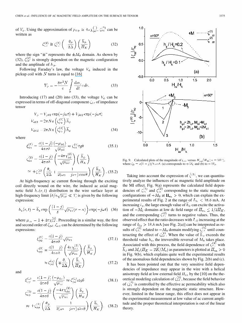
Fig. 9. Calculated plots of the magnitude of � versus H =H (� = 50 ),where � = c(1� j)=4���. (a) corresponds to +M and (b) to �M .
Taking into account the expression of , we can quantita-tively analyze the influences of ac magnetic field amplitude onthe MI effect. Fig. 9(a) represents the calculated field depen-dencies of and corresponding to the static magneticconfigurations of at , which can explain the ex-perimental results of Fig. 2 at the range of mA. Atincreasing , the large enough value of can excite the activa-tion of domains at low dc field range of ,and the corresponding turns to negative values. Thus, theobserved effect that the ratio decreases with increasing at therange of mA [see Fig. 2(a)] can be interpreted as re-sults of related to domain modifying until coun-teracting the effect of . When the value of exceeds thethreshold value , the irreversible reversal of takes place.Associated with this process, the field dependence of with
and as parameters is plotted atin Fig. 9(b), which explains quite well the experimental resultsof the anomalous field dependencies shown by Fig. 2(b) and (c).
It has been pointed out that the very sensitive field depen-dencies of impedance may appear in the wire with a helicalanisotropy field at low external field by the [10] on the the-oretical modeling calculation of , because the field behaviorof is controlled by the effective ac permeability which alsois strongly dependent on the magnetic static structure. How-ever, limited in the linear range, this effect does not appear inthe experimental measurement at low value of ac current ampli-tude and the proper theoretical interpretation is out of the lineartheory.
3376 IEEE TRANSACTIONS ON MAGNETICS, VOL. 40, NO. 5, SEPTEMBER 2004
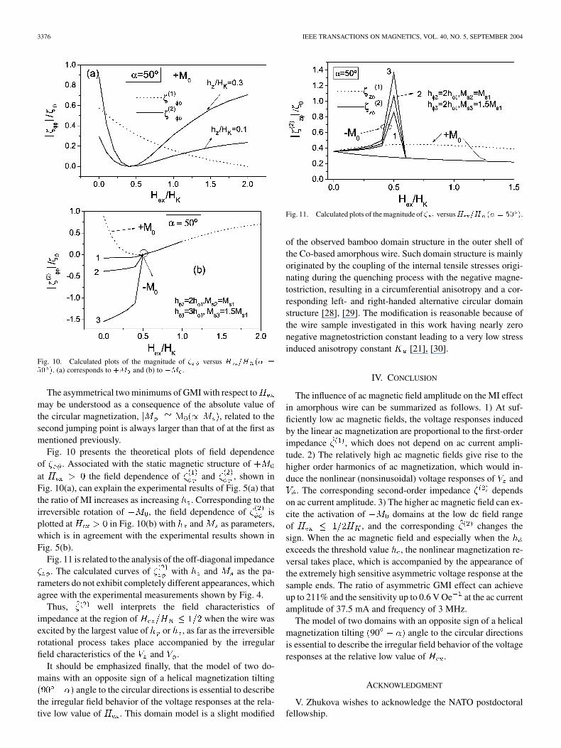
Fig. 10. Calculated plots of the magnitude of � versus H =H (� =50 ). (a) corresponds to +M and (b) to �M .
The asymmetrical two minimums of GMI with respect tomay be understood as a consequence of the absolute value ofthe circular magnetization, , related to thesecond jumping point is always larger than that of at the first asmentioned previously.
Fig. 10 presents the theoretical plots of field dependenceof . Associated with the static magnetic structure ofat the field dependence of and , shown inFig. 10(a), can explain the experimental results of Fig. 5(a) thatthe ratio of MI increases as increasing . Corresponding to theirreversible rotation of , the field dependence of isplotted at in Fig. 10(b) with and as parameters,which is in agreement with the experimental results shown inFig. 5(b).
Fig. 11 is related to the analysis of the off-diagonal impedance. The calculated curves of with and as the pa-
rameters do not exhibit completely different appearances, whichagree with the experimental measurements shown by Fig. 4.
Thus, well interprets the field characteristics ofimpedance at the region of when the wire wasexcited by the largest value of or , as far as the irreversiblerotational process takes place accompanied by the irregularfield characteristics of the and .
It should be emphasized finally, that the model of two do-mains with an opposite sign of a helical magnetization tilting
angle to the circular directions is essential to describethe irregular field behavior of the voltage responses at the rela-tive low value of . This domain model is a slight modified
Fig. 11. Calculated plots of the magnitude of � versusH =H (� = 50 ).
of the observed bamboo domain structure in the outer shell ofthe Co-based amorphous wire. Such domain structure is mainlyoriginated by the coupling of the internal tensile stresses origi-nating during the quenching process with the negative magne-tostriction, resulting in a circumferential anisotropy and a cor-responding left- and right-handed alternative circular domainstructure [28], [29]. The modification is reasonable because ofthe wire sample investigated in this work having nearly zeronegative magnetostriction constant leading to a very low stressinduced anisotropy constant [21], [30].
IV. CONCLUSION
The influence of ac magnetic field amplitude on the MI effectin amorphous wire can be summarized as follows. 1) At suf-ficiently low ac magnetic fields, the voltage responses inducedby the linear ac magnetization are proportional to the first-orderimpedance , which does not depend on ac current ampli-tude. 2) The relatively high ac magnetic fields give rise to thehigher order harmonics of ac magnetization, which would in-duce the nonlinear (nonsinusoidal) voltage responses of and
. The corresponding second-order impedance dependson ac current amplitude. 3) The higher ac magnetic field can ex-cite the activation of domains at the low dc field rangeof , and the corresponding changes thesign. When the ac magnetic field and especially when theexceeds the threshold value , the nonlinear magnetization re-versal takes place, which is accompanied by the appearance ofthe extremely high sensitive asymmetric voltage response at thesample ends. The ratio of asymmetric GMI effect can achieveup to 211% and the sensitivity up to 0.6 V Oe at the ac currentamplitude of 37.5 mA and frequency of 3 MHz.
The model of two domains with an opposite sign of a helicalmagnetization tilting 90 angle to the circular directionsis essential to describe the irregular field behavior of the voltageresponses at the relative low value of .
ACKNOWLEDGMENT
V. Zhukova wishes to acknowledge the NATO postdoctoralfellowship.
CHEN et al.: INFLUENCE OF AC MAGNETIC FIELD AMPLITUDE ON THE SURFACE MI TENSOR 3377
REFERENCES
[1] R. S. Beach and A. E. Berkowitz, “Giant magnetic field dependentimpedance of amorphous FeCoSiB wire,” Appl. Phys. Lett., vol. 64, p.3652, 1994.
[2] L. V. Panina and K. Mohri, “Magneto-impedance effect in amorphouswires,” Appl. Phys. Lett., vol. 65, p. 1185, 1994.
[3] J. Velázquez, M. Vázquez, D.-X. Chen, and A. Hernando, “Giant mag-netoimpedance in nonmagnetostrictive amorphous wires,” Phys. Rev. B,vol. 50, p. 16 737, 1994.
[4] K. V. Rao, F. B. Humphrey, and J. L. Costa-Krämer, “Very large mag-netoimpedance in amorphous soft ferromagnetic wires,” J. Appl. Phys.,vol. 76, p. 6204, 1994.
[5] K. Mohri, L. V. Panina, K. T. Uchiyama, K. Bushida, and M. Noda,“Sensitive and quick response micro magnetic sensor utilizing magneto-impedance in Co-rich amorphous wires,” IEEE Trans. Magn., vol. 31,pp. 1266–1275, Mar. 1995.
[6] L. V. Panina, K. Mohri, K. Bushida, and M. Noda, “Giant magneto-impedance in Co-rich amorphous wires and films,” IEEE Trans. Magn.,vol. 31, pp. 1249–1260, Mar. 1995.
[7] M. Vazquez and A. Hernado, “A soft magnetic wire for sensor applica-tions,” J. Phys. D, Appl. Phys., vol. 29, p. 939, 1996.
[8] A. Yelon, D. Ménard, M. Britel, and P. Ciureanu, “Calculations of giantmagnetoimpedance and of ferromagnetic resonance response are rigor-ously equivalent,” Appl. Phys. Lett., vol. 69, p. 3084, 1996.
[9] D. P. Makhnovskiy, L. V. Panina, and D. J. Mapps, “Measurement offield-dependent surface impedance tensor in amorphous wires with cir-cumferential anisotropy,” J. Appl. Phys., vol. 87, p. 4804, 2000.
[10] , “Field-dependent surface tensor in amorphous wires with twotypes of magnetic anisotropy: helical and circumferential,” Phys. Rev.B, vol. 63, p. 144 424, 2001.
[11] P. Aragoneses, A. P. Zhukov, J. Gonzalez, J. M. Blanco, and L.Dominguez, “Effect of AC driving current on magneto-impedanceeffect,” Sens. Actuators A, vol. 81, p. 86, 2000.
[12] L. Domínguez, J. M. Blanco, P. Aragoneses, and J. González, “Circum-ferential magnetization processes in CoFeBSi wires,” J. Appl. Phys., vol.79, p. 6539, 1996.
[13] J. J. Freijo, Ph.D. dissertation, Univ. Complutense de Madrid, Madrid,Spain, 2001.
[14] R. S. Beach, M. Smith, C. L. Platt, F. Jeffers, and A. E. Berkowitz, “Mag-netoimpedance effect in NiFe plated wire,” Appl. Phys. Lett., vol. 68, p.2753, 1996.
[15] H. Chiriac, E. Hristoforou, M. Neagu, I. Darie, and F. Barariu, “D.C.magnetic field measurements based on the inverse Wiedemann effect inFe-rich glass covered amorphous wires,” IEEE Trans. Magn., vol. 35,pp. 3625–3627, Sept. 1999.
[16] A. S. Antonov, N. A. Buznikov, I. T. Iakubov, A. N. Lagarkov, and A. L.Rakhmanov, “Nonlinear magnetization reversal of Co-based amorphousmicrowires induced by an ac current,” J. Phys. D, Appl. Phys., vol. 34,p. 752, 2001.
[17] C. Gómez-Polo, M. Vazquez, K. R. Pirota, and M. Knobel, “Giant mag-netoimpedance modeling using Fourier analysis in soft magnetic amor-phous wires,” Phys. B, vol. 299, p. 322, 2001.
[18] V. A. Zhukova, A. B. Chizhik, J. González, D. P. Makhnovskiy, L. V.Panina, D. J. Mapps, and A. P. Zhukov, “Effect of annealing under tor-sion stress on the field dependence of the impedance tensor in amorphouswires,” J. Magn. Magn. Mater., vol. 249, p. 324, 2002.
[19] D. P. Makhnovskiy, L. V. Panina, and D. J. Mapps, “Asymmetrical mag-netoimpedance in as-cast CoFeSiB amorphous wires due to ac bias,”Appl. Phys. Lett., vol. 77, p. 121, 2000.
[20] L. D. Landau and E. M. Lifshitz, Electrodynamics of Continuous Media,2nd ed. New York: Pergamon, 1984.
[21] K. Mohri et al., “Large Barkhausen and Matteucci effects in FeCoSiB,FeCrSiB and FeNiSiB amorphous wires,” IEEE Trans. Magn., vol. 26,pp. 1789–1791, Sept. 1990.
[22] F. B. Humphrey and K. Mohri et al., “Re-entrant magnetic flux reversalin amorphous wires,” in Magnetic Properties of Amorphous Metals,A. Hernando, V. Madurga, M. C. Sánchez-Trujillo, and M. Vázquez,Eds. Amsterdam, The Netherlands: North-Holland, 1987, vol. 110.
[23] E. C. Stoner and E. P. Wohlfarth, “A mechanism of magnetic hysteresisin heterogeneous alloys,” Phil. Trans. R. Soc., vol. A-240, pp. 599–642,1948.
[24] A. S. Antonov, N. A. Buznikov, A. B. Granovsky, I. T. Iakubov, A.F. Prodoshin, A. L. Radhmanov, and A. M. Yakunin, “Magnetizationreversal process and nonlinear magnetoimpedance in Cu/NiFe andNb/NiFe composite wires,” J. Magn. Magn. Mater., vol. 249, p. 315,2002.
[25] A. S. Antonov, N. A. Buznikov, M. M. Filatov, V. P. Goncharov, A. A.Rakhmano, and A. L. Rakhmanov, “Effects of longitudinal AC magneticfield on frequency spectrum of voltage response of soft magnetic con-ductors,” J. Magn. Magn. Mater., vol. 258, p. 198, 2003.
[26] K. H. Zhao and X. M. Chen, “Electromagnetism (II),” in People’s Edu-cation: Bei Jin P, 1978, p. 207.
[27] D.-X. Chen, L. Pascual, F. J. Castaño, M. Vazquez, and A. Hernando,“Revised core-shell domain model for magnetostrictive amorphouswires,” IEEE Trans. Magn., vol. 37, pp. 994–1002, Mar. 2001.
[28] M. Takajo, J. Yamasaki, and F. B. Humphrey, “Domain observations ofFe and Co based amorphous wires,” IEEE Trans. Magn., vol. 30, pp.3484–3486, Nov. 1993.
[29] I. Ogasawara and K. Mohri, “Preparation and properties of amorphouswires,” IEEE Trans. Magn., vol. 26, p. 1219, 1995.
[30] A. Chizhik, V. Zhukova, A. Zhukov, J. M. Blanco, and J. Gonzalez, “Ef-fect of annealing on surface domain structure and magnetostriction ofnear-zero magnetostrictive Co-rich wire,” J. Magn. Magn. Mater., vol.242, p. 244, 2002.
Copyright © 2022 FDOKUMEN