
Influence de l'électrolyte et/ou du liant sur la chimie de surface ...
205
HAL Id: tel-03722801 https://pastel.archives-ouvertes.fr/tel-03722801 Submitted on 13 Jul 2022 HAL is a multi-disciplinary open access archive for the deposit and dissemination of sci- entific research documents, whether they are pub- lished or not. The documents may come from teaching and research institutions in France or abroad, or from public or private research centers. L’archive ouverte pluridisciplinaire HAL, est destinée au dépôt et à la diffusion de documents scientifiques de niveau recherche, publiés ou non, émanant des établissements d’enseignement et de recherche français ou étrangers, des laboratoires publics ou privés. Influence de l’électrolyte et/ou du liant sur la chimie de surface et les performances électrochimiques de l’électrode à base de Si et de l’électrode métallique Li pour batteries au lithium Zhanyu Wu To cite this version: Zhanyu Wu. Influence de l’électrolyte et/ou du liant sur la chimie de surface et les performances électrochimiques de l’électrode à base de Si et de l’électrode métallique Li pour batteries au lithium. Chimie analytique. Université Paris sciences et lettres, 2021. Français. NNT : 2021UPSLC005. tel-03722801
-
Upload
khangminh22 -
Category
Documents
-
view
0 -
download
0
Transcript of Influence de l'électrolyte et/ou du liant sur la chimie de surface ...

HAL Id: tel-03722801https://pastel.archives-ouvertes.fr/tel-03722801
Submitted on 13 Jul 2022
HAL is a multi-disciplinary open accessarchive for the deposit and dissemination of sci-entific research documents, whether they are pub-lished or not. The documents may come fromteaching and research institutions in France orabroad, or from public or private research centers.
L’archive ouverte pluridisciplinaire HAL, estdestinée au dépôt et à la diffusion de documentsscientifiques de niveau recherche, publiés ou non,émanant des établissements d’enseignement et derecherche français ou étrangers, des laboratoirespublics ou privés.
Influence de l’électrolyte et/ou du liant sur la chimie desurface et les performances électrochimiques de
l’électrode à base de Si et de l’électrode métallique Lipour batteries au lithium
Zhanyu Wu
To cite this version:Zhanyu Wu. Influence de l’électrolyte et/ou du liant sur la chimie de surface et les performancesélectrochimiques de l’électrode à base de Si et de l’électrode métallique Li pour batteries au lithium.Chimie analytique. Université Paris sciences et lettres, 2021. Français. �NNT : 2021UPSLC005�.�tel-03722801�

Ecole doctorale n° 388 Chimie physique et chimie analytique de Paris centre
Spécialité Physico-chimie
Composition du jury :
Mme Nathalie Herlin Boime Directrice de Recherche, CEA Présidente M. Alexandre Chagnes Professeur, Université de Lorraine Rapporteur M. Eric de Vito Ingénieur de recherche, CEA Rapporteur M. Philippe Marcus Directeur de Recherche, Chimie ParisTech Co-encadrant Mme Jolanta Światowska Directrice de Recherche, Chimie ParisTech Directrice de thèse
Soutenue par Zhanyu WU Le 2 mars 2021
Préparée à Chimie ParisTech
Influence of electrolyte and/or binder on surface chemistry and electrochemical performances of Si-based and Li metal
electrodes for lithium batteries


III
Table of contents
Abstract ................................................................................................. 1
Chapter 1 Bibliographic studies ........................................................ 5
1.1 Brief introduction of lithium ion batteries ......................................... 5
1.1.1 History of LIB ................................................................................................5
1.1.2 Working principle of LIBs..............................................................................6
1.2 Towards higher energy density LIBs ................................................ 8
1.3 Anode materials ................................................................................ 9
1.3.1 Carbon-based materials ..................................................................................9
1.3.2 Conversion materials ......................................................................................9
1.3.3 Lithium alloys .............................................................................................. 10
1.3.3.1 Sn-, Sb-, Al- and Ge-based anodes ........................................................... 10
1.3.3.2 Si-based materials .................................................................................... 11
1.3.3.2.1 Nanostructured Si-based anode materials ............................................ 12
1.3.3.2.2 Si-based composite materials .............................................................. 13
1.3.4 Li metal anode .............................................................................................. 14
1.4 Binders ..........................................................................................16
1.5 Electrolyte .......................................................................................19
1.5.1 Electrolyte for graphite anode ....................................................................... 20
1.5.2 Electrolyte for Si anode ................................................................................ 20
1.5.3 Electrolyte for Li metal anode ...................................................................... 22
1.6 Interface characterization techniques ...............................................22
1.6.1 X-ray photoelectron spectroscopy................................................................. 23
1.6.2 Time-of-flight secondary ion mass spectrometry .......................................... 24

IV
1.6.3 Fourier-transform infrared spectroscopy ....................................................... 24
1.7 Objectives and primary content of thesis .........................................25
References ...........................................................................................28
Chapter 2 Instruments and experimental methods ........................45
2.1. X-ray photoelectron spectroscopy (XPS) ........................................45
2.2 Time-of-flight secondary ion mass spectrometry (ToF-SIMS) .........46
2.3 Fourier transform infrared spectroscopy (FTIRS) ............................47
2.4 Raman spectroscopy ........................................................................48
2.5 Scanning electron microscopy (SEM) ..............................................49
2.6 Atomic force microscope (AFM) .....................................................49
2.7 Thermogravimetric analysis (TGA) .................................................50
2.8 Electrochemical measurements ........................................................50
2.8.1 Cyclic voltammetry (CV) ............................................................................. 50
2.8.2 Linear sweep voltammetry (LSV) ................................................................. 51
2.8.3 Galvanostatic charge-discharge .................................................................... 51
2.8.4 Electrochemical impedance spectroscopy (EIS) ............................................ 51
2.9 Magnetron sputtering .......................................................................52
References ...........................................................................................53
Chapter 3 Influence of carbonate solvents on SEI composition
over Si electrode monitored by in situ and ex situ spectroscopies................................................................................................................55
3.1 Introduction .....................................................................................55
3.2 Experimental part ............................................................................57
3.2.1 Sample preparation ....................................................................................... 57

V
3.2.2 Electrochemical tests .................................................................................... 57
3.2.3 X-ray photoelectron spectroscopy................................................................. 58
3.2.4 In situ microscope Fourier transform infrared spectroscopy .......................... 59
3.2.5 Time-of-flight secondary ion mass spectrometry .......................................... 59
3.3 Results and discussion .....................................................................59
3.3.1 Influence of lithiation/delithiation on the surface modifications of Si by XPS
........................................................................................................ 59
3.3.1.1 Cyclic voltammetry of Si thin film electrode for sample preparation ........ 59
3.3.1.2 SEI layer formation in DMC-based electrolyte studied by XPS ................ 60
3.3.1.3 SEI layer evolution in EC-DMC, DMC and PC-based electrolytes ........... 64
3.3.1.4 SEI layer evolution with cycling .............................................................. 66
3.3.2 Surface and bulk thin film Si electrode modifications by ToF-SIMS ion depth
profiles ........................................................................................................ 67
3.3.3 Influence of lithiation/delithiation on the electrolyte components by in situ
MFTIRS ........................................................................................................ 73
3.3.3.1 Cyclic voltammetry of Si thin film electrode during in situ MFTIRS ....... 73
3.3.3.2 In situ MFTIRS........................................................................................ 74
3.3.4 Morphology of Si electrodes after 1 CV cycle in different electrolytes .......... 76
3.3.5 Galvanostatic tests of Si thin film electrode in different electrolytes ............. 77
3.3.6 Summary on surface and interface characterizations ..................................... 78
3.4 Conclusions .....................................................................................79
References ...........................................................................................80
Supplementary informations ..................................................................87
Chapter 4 Influence of different binders on SEI formation on Si-
based electrode ....................................................................................97
4.1 Introduction .....................................................................................97

VI
4.2 Experimental part ............................................................................98
4.2.1 Electrode preparations .................................................................................. 98
4.2.2 Electrochemical tests .................................................................................... 99
4.2.3 XPS characterizations ................................................................................... 99
4.3 Results and discussion ................................................................... 100
4.3.1 Cyclic voltammetry tests for XPS characterizations .................................... 100
4.3.2 Surface characterizations by XPS ............................................................... 100
4.3.3 Galvanostatic results................................................................................... 112
4.4 Conclusions ................................................................................... 113
References ......................................................................................... 115
Supplementary informations ................................................................ 119
Chapter 5 Development of a binder free Si@C-network electrode
and its influence on SEI layer formation ...................................... 121
5.1 Introduction ................................................................................... 121
5.2 Experimental part .......................................................................... 122
5.2.1 Electrode preparation ................................................................................. 122
5.2.1.1 Preparation of Si@C-network electrode ................................................. 122
5.2.1.2 Preparation of binder containing Si-XG-AB electrode............................ 122
5.2.2 Characterizations of pristine electrodes....................................................... 123
5.2.3 XPS and ToF-SIMS analyzations ................................................................ 123
5.2.3.1 Sample preparation for XPS and ToF-SIMS ........................................... 123
5.2.3.2 XPS and ToF-SIMS experimental conditions ......................................... 124
5.2.4 Galvanostatic tests ...................................................................................... 124
5.3 Results and discussion ................................................................... 124
5.3.1 Fourier transform infrared spectrometry, Raman spectroscopy and

VII
thermogravimetric analyzations........................................................................... 124
5.3.2 Morphology characterizations and electrochemical tests ............................. 126
5.3.2.1 Morphological characterization of electrodes by SEM and TEM ............ 126
5.3.2.2 Galvanostatic tests ................................................................................. 127
5.3.3 XPS surface characterizations..................................................................... 128
5.3.4 ToF-SIMS surface and bulk characterizations ............................................. 135
5.4 Conclusions ................................................................................... 140
References ......................................................................................... 141
Supplementary informations ................................................................ 145
Chapter 6 Heterogeneous SEI film with outer/inner hybrid
electronic/ionic conductive structure for high-energy density of
Li-metal batteries .............................................................................. 147
6.1 Introduction ................................................................................... 147
6.2 Experimental part .......................................................................... 149
6.2.1 Materials .................................................................................................... 149
6.2.2 Cell fabrication and electrochemical tests ................................................... 149
6.2.3 Materials characterization ........................................................................... 150
6.2.4 Calculation methods ................................................................................... 151
6.3 Results and discussion ................................................................... 151
6.3.1 The mechanism of heterogeneous SEI film formation ................................. 151
6.3.2 Identification of heterogeneous SEI stucture ............................................... 153
6.3.3 Effect of heterogeneous SEI film on Li dendrites and Li loss ...................... 158
6.3.4 Effect of heterogeneous SEI film on Li/electrolyte interface ....................... 159
6.3.5 High-cyclability and high-voltage Li metal batteries ................................... 161
6.4 Conclusions ................................................................................... 163

VIII
References ......................................................................................... 165
Supplementary informations ................................................................ 169
Annexe 1: List of abbreviations ............................................... 175
Annexe 2 : Résumé étendu en français des travaux présentés dans
la thèse ..................................................................................... 179
Conclusions and perspectives ......................................................... 191
Acknowledgements .......................................................................... 195

1
Abstract
Lithium ion batteries (LIBs) are nowadays widely applied all over the world as the most
popular energy storage devices for portable electronic equipment and electric vehicles.
However, the current commercial electrode materials for LIBs no longer meet the increasing
demands of energy density, cycle life, rate capability. Therefore, it is imperative to develop new
generation negative and positive electrode materials to meet these requirements.
Si has been considered as a promising candidate for negative electrode material due to its
low cost, natural abundance and especially its high theoretical capacity (3580 mAh g-1).
However, Si suffers from large volume changes during the charge/discharge processes, which
results in material pulverizations and capacity fading. In addition, the huge volume changes
break the solid electrolyte interface (SEI) layer every cycle and results in the SEI continuous
formation, which irreversibly consumes a considerable amount of the electrolyte.
Li metal has been employed as the negative electrode material for the earliest commercial
rechargeable Li batteries in 1970s. However, growth of Li dendrites during electrodeposition
inhibits its application for many years. The growth of Li dendrites not only causes the short
circuit problem of the battery, but also makes Li trapped by the SEI layer around it and results
in “dead Li”, which decreases the coulombic efficiency. In recent years, with the developments
of electrolytes, separators, and other battery components, the Li metal anode has attracted more
and more research interests.
As introduced above, the SEI layer plays a key role for the reversibility of Si-based anode
and Li metal anode. The aim of this work was to explore the SEI layer formation processes
when influenced by different factors. Here, the influence of electrolytes, additives and binders
to the formation of SEI layer were chosen to be investigated.
Several surface analytical techniques, such as X-ray Photoelectron Spectroscopy (XPS),
Fourier-transform infrared spectroscopy (FTIRS) and Time-of-Flight Secondary Ion Mass
Spectrometry (ToF-SIMS), can be applied to study the composition of SEI layer. XPS can be
used to identify species at different chemical states on the surface. By the ion gun sputtering, it
can give the information of sample with depth. FTIR can show the small bonding energy
difference between different organic species on electrode surface or in electrolyte. ToF-SIMS
can give the elements/species distribution on the sample surface and the bulk. In this work, XPS,
FTIRS and ToF-SIMS methods were ex situ and in situ applied to investigate the changes of

2
SEI layer with the variation of potential on the electrode.
This manuscript contains six chapters.
Chapter 1 is a bibliographic study, which starts with the introduction of LIBs, history and
working principle. Then, different kinds of anode materials for high energy density LIBs are
introduced, especially the Si-based anode and Li metal anode. After that, the binders and the
electrolytes, which are both important components in the battery system are presented. Then
the application of surface analytical techniques, XPS, FTIRS and ToF-SIMS, on batteries
especially on Si-based anode and Li metal anode are summarized. Finally, the objective of this
work is presented.
Chapter 2 presents the analyzation and material fabrication methods used in this work. The
main surface analytical methods XPS, FTIRS and ToF-SIMS are introduced. Then, the other
surface characterization and electrochemical techniques, which are used to confirm the surface
processes and the sample preparation, are presented. At last, the magnetron sputtering method
for electrode fabrication is introduced.
Chapter 3 compares the different SEI formation on Si thin film electrode with three LiPF6-
based carbonate electrolytes. The linear carbonate DMC, cyclic carbonate PC and the mixture
of cyclic and linear carbonate EC-DMC were used as the solvents, respectively. The electrode
surfaces were analyzed by XPS, ToF-SIMS and in situ FTIRS at different electrochemical states
during the cyclic voltammetry (CV) tests. The different roles of linear and cyclic carbonate
solvents during the SEI formation are discussed.
Chapter 4 compares the SEI layer formed on Si nanoparticle anodes with different binders,
which have different functional groups (-OH, -COOH, -NH2, etc.). XPS is used to analyze the
surface layer at fully lithiated and fully delithiated states. Different comparisons were made to
demonstrate the influence of -COOH, -OH, -NH2 and cross-link structure of binders.
Chapter 5 introduces the design and fabrication of binder-free Si@C-network electrode.
Then the SEI layer formed on Si@C-network electrode was investigated by XPS and ToF-
SIMS at different states of lithiation and delithiation.
Chapter 6 is the work performed in cooperation with the group in Xiamen University. It
shows the electrochemical performance of Li metal anode, which is significantly improved with
the addition of LiNO3 and EC in tetra-ethylene glycol dimethyl ether (TEGDME)-based
electrolyte. Then, the composition of SEI layer on the electrode with this electrolyte were
investigated by XPS with ion sputtering, atomic force microscopy (AFM) and density

3
functional theory (DFT) calculations. A heterogenous SEI model with two layers was proposed
based on the characterization results.
In the final part, the main conclusions and perspectives of this thesis are given.

4

5
Chapter 1
Bibliographic studies
1.1 Brief introduction of lithium ion batteries
With the developments of scientific technologies, the demand of energy supplement is
continuous increasing in our society. However, the massive utilization of fossil fuels in the past
several decades results in many environmental and ecological problems (e.g. global greenhouse
effect, water and air pollution, etc.). Therefore, it is very important to develop renewable
energies and to achieve the sustainable development of human society.
In recent years, the researches about renewable energies such as solar energy, tidal energy
and wind energy attract extensive attention. The proportions of renewable energy supplements
are increasing in many countries. However, these energies cannot be output constantly for a
long time due to the limits by time and space. Thus, it is very necessary to establish a stable
system for energy conversion and storage. The rechargeable battery system is one of the most
commonly used methods.
Comparing with the traditional rechargeable batteries, such as Ni-H battery and Pb-acid
battery, lithium ion battery (LIB) shows many advantages. It is more environmentally friendly.
It has higher work potential, higher energy density, longer cycle life and no memory effect
during charge/discharge processes. It has been widely used in portable electronic equipment,
electric vehicles (EVs) and hybrid electric vehicles (HEVs). When establishing an energy
conversion and storage system, LIB is also more competitive than other traditional secondary
batteries [1].
1.1.1 History of LIB
In 1950s, researchers put forward the idea of lithium primary battery with lithium as the
negative electrode because lithium shows the lowest density (0.534 g cm-1) and the lowest
standard electrode potential (-3.045 V) which result in relatively high work potential and high
energy density of the primary lithium battery [2].
In 1970s, the lithium primary battery was industrialized and the lithium secondary battery
was being developed. However, during the charge/discharge processes of the lithium secondary
battery, the dendrites will easily form on the lithium surface, which puncture the separator and

6
result in the short circuit [3]. In order to solve this safety problem, the lithium ion secondary
battery which achieves the energy storage by lithium ion insertion and extraction was proposed
and received widespread attention. In 1970s, Whittingham et al. purposed the concept of
intercalation electrodes and developed the first working rechargeable battery based on lithium
ion transfer with TiS2 cathode and Li metal anode [4]. In 1980, Goodenough et al. first reported
the layered oxide LiCoO2 could be used as the cathode material for LIB [5]. In 1985, Yoshino
et al. developed carbonaceous material as the anode material of the LIB [6]. Six years later,
SONY company achieved the commercial application of lithium ion secondary battery using
LiCoO2 as the cathode material and graphite as the anode material, which successfully solved
the problem of lithium dendrite formation and greatly improved the safety of battery. In 2019,
John B. Goodenough, M. Stanley Whittingham and Akira Yoshino received the Nobel Prize in
Chemistry for their contribution to the key development of LIBs.
In the recent 30 years, LIBs have entered thousands of households along with electronic
devices such as mobile phones, cameras, and laptop computers, and successfully used as the
power source for EVs and HEVs, occupying an important position in the field of energy storage.
With the development of LIBs’ commercial application, more and more researches about LIBs
have been reported. From 1990 to 2010, around 79,000 papers about LIBs were published.
From 2010 to 2020, this number increases to more than 337,000 (data provided by Google
scholar).
1.1.2 Working principle of LIBs
The working principle of LIB is shown in Fig. 1.1. When the battery is charged, Li+ is
released from the cathode material loaded on the Al current collector, and then solvated into the
electrolyte. On the anode, Li+ migrates from the electrolyte into the anode material with a
desolvation reaction. During this process, electrons migrate from the positive electrode to the
negative electrode. The discharge process of the battery is the opposite. Li in the anode material
is oxidized to Li+ and extracted into the electrolyte. On the positive electrode, Li+ transfers from
the electrolyte and intercalates into the cathode material. In the external circuit, the electrons
move from the positive electrode to the negative electrode during the charging process.
For example, in the most widely used LiCoO2/graphite lithium-ion battery, LiCoO2 is used
as the battery cathode material, layered graphite (C6) is used as the anode material. The
electrolyte is prepared by dissolving 1 mol L-1 LiPF6 in a mixture of ethylene carbonate (EC),
dimethyl carbonate (DMC) and diethyl carbonate (DEC) with 1:1:1 volume ratio. The battery

7
system can be shown as follows:
(-) C6 | 1M LiPF6-EC: DMC: DEC (1:1:1) | LiCoO2 (+)
The charge-discharge battery reactions can be shown as:
Fig. 1.1 Schematic illustration of the first Li-ion battery (LiCoO2/Li+ electrolyte/graphite) [7].
During the electrochemical processes of the battery, if the cathode potential is below the
highest occupied molecular orbital (HOMO) of electrolyte, the electrolyte will oxidized unless
a passivation Cathode electrolyte interphase (CEI) layer blocks electron transfer from the
electrolyte HOMO to the cathode. If the anode potential is above the lowest unoccupied
molecular orbital (LUMO) of electrolyte, the electrolyte will be reduced unless a passivation
solid electrolyte interphase (SEI) layer creates a barrier to electron transfer from the anode to
the electrolyte LUMO. Therefore, thermodynamic stability requires locating the cathode and

8
anode electrochemical potentials within the window of the electrolyte. The passivation layer at
the electrode/electrolyte boundary can give a kinetic stability to a larger opencircuit voltage
(Eanode-Ecathode) of a battery cell [8].
1.2 Towards higher energy density LIBs
In nowadays, the different demands of energy storage equipment are continuously rising,
such as higher energy density, longer cycle life, faster charging capability, lower price, less
harmful to environment and good safety. The current commercial cathode and anode materials
for lithium-ion batteries no longer meet the increasing requirements. Thus, it is imperative to
develop a new generation battery system with these good properties.
The energy density of battery can be calculated by the following formula:
P = E * C (1-4)
P: Specific energy or energy density (Wh/kg);
E: Battery nominal voltage (V);
C: Battery specific capacity rating (Ah/kg)
Therefore, the researches on high voltage cathode materials and high specific capacity cathode
and anode materials and high voltage stable electrolytes are the key ways to improve battery
energy density. Currently, the research interests of cathode materials for lithium-ion batteries
Fig. 1.2 Schematic illustration of active anode materials for the next generation of lithium
batteries. Potential vs. Li/Li+ and the corresponding capacity density are shown [19].

9
mainly focus on LiNixCoyMnzO2, LiNixCoyAlzO2 materials, Li-rich materials and so on [9-12].
The anode material studies for LIBs mainly focus on Si, Ge, Sn and Sb alloy materials,
transition metal compound materials and Li metal anode materials [13-17]. Fig. 1.2 shows the
candidates of the anode materials for next generation LIBs with their working potentials and
corresponding theoretical capacity regions. The alloy materials, transition metal compounds
and Li metal anode materials present higher capacity than the graphite anode. However, they
still have different disadvantages need to be solved, such as huge volume expansion, poor
conductivity, high working potential or Li dendrite growth [18]. The detail introduction of these
new generation anode materials will be shown in the next section of this chapter.
1.3 Anode materials
1.3.1 Carbon-based materials
The main anode materials used in commercial lithium-ion batteries now are carbon-based
materials. This type of material has the advantages of good conductivity, small volume change
during charge and discharge, high charge and discharge coulombic efficiency, low price, and
no pollution. There are different kinds of the carbon-based material such as graphite, mesophase
carbon microspheres (MCMB), hard carbon and graphene [20-22]. Graphite is most widely
applied among them.
Graphite is a kind of anode material with a layered structure. The carbon atoms in each
layer are distributed in a hexagonal honeycomb plane. The theoretical specific capacity of the
graphite anode is 372 mAh g-1. During the discharge process, lithium ions enter the graphite
layer to form LiC6 with an obvious discharge plateau at the potential lower than 0.3 V. The van
der Waals force between the graphite layers is relatively weak. Thus, during the charging and
discharging process, the graphite layers will easily shift, peel off and expand the layer spacing
due to the co-intercalation of Li+ and solvent molecules. The main method to solve this problem
is adding EC and other components to the electrolyte solvent to reduce the electrolyte during
the first discharge process to form a SEI layer covering the surface of the graphite and protecting
it from further electrolyte decomposition [23,24]. However, it results in a high irreversible
capacity of graphite anode during the first charge-discharge process.
1.3.2 Conversion materials
The transition metal compounds, such as oxides, phosphides, nitrides and sulfides were

10
demonstrated as the anode materials for Li ion batteries with relatively high theoretical
capacities (~500 mAh g-1-1400 mAh g-1).
The lithium insertion processes into these transition compounds are called conversion reactions.
As shown in the reaction (1-5), during discharge process, Li+ reacts with negative electrode
material AxBy to produce LixB and A0 (A = Fe, Co, Ni, Mn, Cu, Zn, Cr, etc., B = O, P, N, S).
The LixB and A0 are reversibly converted into Li+ and AxBy during the charge process [19].
(1-5)
The transition metal compound anode materials usually exhibit relatively low volume
expansion during the charge-discharge processes. However, these materials usually have high
lithium insertion potential, poor conductivity and reversibility. To solve these problems,
researchers often use methods such as nanomaterial synthesis and carbon coating to improve
their electrochemical performance [19,25-27].
1.3.3 Lithium alloys
1.3.3.1 Sn-, Sb-, Al- and Ge-based anodes
Sn, Sb, Al, Ge and some other materials (elements of 13, 14 and 15 column/groups of
periodic table of elements) can be used as the anode materials for Li-ion batteries. These
materials form an alloy with lithium during the discharge process. Not like the lithium metal
anodes, these alloy anode materials do not generate lithium dendrites during lithium insertion.
Comparing with graphite anodes, these alloy anode materials do not have the problem of solvent
molecule co-intercalation, which makes the battery safer. At the same time, the alloy-type
compound has higher theoretical lithium insertion amount. Thus, the alloy-type anode materials
usually have higher theoretical specific capacities (e.g. LixSn 788 mA h g-1, LixSb 660 mA h
g−1, LixAl 2235 mAh g-1 and LixGe 1623 mAh g-1) [28,29]. However, due to the large amount
of lithium insertion and extraction during charge-discharge processes, there is often a huge
volume variation during the cycling, which causes the electrode material broken, pulverized
and peeled off from the current collector. Then the capacity is rapidly attenuated. In addition,
several of the alloy-type compounds are semiconductor materials, and the intrinsic conductivity
of these materials is low, resulting in poor rate performance of the electrode [29]. To solve these
problems, researchers tried to fabricate nanomaterials and composites to reduce cracks caused
by volume changes [30-32], or carbon coated materials to buffer the volume changes and
enhance the conductivity [33,34].

11
1.3.3.2 Si-based materials
Silicon, which also forms an alloy with lithium, is a promising anode material for next
generation of high energy density lithium ion batteries. It has the highest theoretical specific
capacity (4200 mAh g-1), higher natural abundance and lower working potential [35]. However,
silicon also exhibits some typical shortcomings of alloy anode materials. It presents the huge
volume change of 300% during the charge and discharge processes, which makes the silicon
electrode material severely pulverized and peels off from the electrode surface, resulting in
rapid electrode capacity fading [28]. On the other hand, the intrinsic conductivity of silicon is
only 6.7*10-4 S cm-1, which seriously limits the rate performance of the silicon anode.
The charge-discharge processes of Si in lithium ion battery are shown as follows:
Fig. 1.3 Charge and discharge curves of silicon anode. Red line: discharge curve (room
temperature); green line: charge curve (room temperature); black line: theoretical lithium
insertion and removal curve (450 °C) [36].
As shown in Fig. 1.3, theoretically, silicon will undergo multiple phase transitions during
the high-temperature lithium insertion process to form LixSi alloys with different lithium
insertion numbers, as shown by the black line. However, at room temperature, the silicon anode
exhibits the charge and discharge curves as the red and green lines. During the lithium insertion
process, the crystalline silicon first changes to amorphous LixSi and then forms crystalline
Li3.75Si when x>3.25. During the delithiation process, crystalline Li3.75Si changes to amorphous

12
Si. There is no Li4.4Si phase formed during charging and discharging at room temperature.
In recent years, in order to improve the electrochemical performance of silicon anode
materials and promote their practical application, researchers made attempts in the preparation
and modification of electrode materials, the development and modification of binders, and the
optimization of electrolytes.
1.3.3.2.1 Nanostructured Si-based anode materials
Liu et al. found that when silicon nanoparticles are small enough, no cracks will occur
during the lithium insertion process by in situ transmission electron microscopy (TEM). The
critical size for the silicon particle which will not crack during lithiation is 150 nm, as shown
in Fig. 1.4 [37]. Similarly, silicon nanowires and silicon nanorods also have critical dimensions
for cracking during lithium insertion [38-40].
Fig. 1.4 Schematic illustration of the critical size of Si nanoparticles during lithiation [37].
Various of methods were used to fabricate different kinds of nano-sized silicon. Gauthier
et al. made nanostructured Si (~10 nm) with micrometric agglomerates (~10 mm) by a low-cost
high energy ball milling method. It provides four times higher tap density than normal Si
nanoparticles and exhibits better cycle stability [41]. Vapor deposition and silica reduction
methods are also widely used for preparing nano-silicon particles [42,43]. Aminu et al. let Si
nanowires grown on a novel 3D interconnected network of binary-phase Cu-silicide nanofoam
substrate. This Si nanowire electrode has an area-loading in excess of 1.0 mg cm-2 and exhibits
a stable areal capacity of ≈2.0 mAh cm-2 after 550 cycles [44]. Chemical etching and
electrochemical deposition can also be used to fabricate silicon nanowires electrode [45,46].
The template method is very popular to prepare Si nanotubes, Si hollow spheres and Si hollow
cubes [47-49]. The nanosized Si thin film electrodes are usually prepared by magnetron
sputtering and chemical vapor deposition (CVD) methods [50-54]. Zhang et al. prepared a 3D

13
nanostructured multilayer Si/Al film electrode, in which Si and Al films were deposited
alternatively onto a 3D nanostructured Cu current collector using magnetron sputtering method.
The multilayer Si/Al film electrode shows high and stable reversible capacity at high current
density of 4.2 A g-1 due to its good conductivity and electrode stability [55]
1.3.3.2.2 Si-based composite materials
The manufacture of Si-based composites is another good way to improve the
electrochemical performance of Si-based anode. Usually the Si-based composite will reduce
the volume expansion during lithium insertion, enhance the conductivity and improve the
interface properties between the electrode and the electrolyte. The experimental conditions and
the choose of experimental materials are more diverse during the synthesis of Si-based
composites. Therefore, it attracts many research interests in these years.
The synthesis of Si/C composites receives the most attention among various fabrications
of Si-based composites, due to the high conductivity and low volume effect during
electrochemical processes of carbon materials. Carbon can effectively buffer the volume change
of silicon and improve rate performance of Si/C composites electrode. Moreover, the synthesis
of Si/C composites usually has simple steps and low cost, which is conducive to large-scale
production and promotes the practical application.
Fig. 1.5 (a) TEM image of Si/C composite; (b) thermogravimetric analysis (TGA) curves of
SiNPs, Si/C composite and pure carbon in air condition from 30 to 800 °C at a heating rate of
10 °C min−1. [67].
There are various ways to prepare Si/C materials. The physical method, mechanical ball
milling, is often utilized to mix silicon with different carbon materials (e.g. graphite, hard

14
carbon, carbon nanotube, graphene, etc.) to be the composites [56-60]. The high temperature
pyrolysis and hydrothermal methods are common used with different carbon sources (e.g. resins,
sugars, organic acids, etc) to coat a carbon layer on the Si surface [61-67]. The TEM image of
the Si/C composite showing a thin carbon layer formed on Si surface and the thermogravimetric
analysis (TGA) curves indicating the carbon weight ratio on this Si/C composite are shown in
Fig. 1.5. The Si/C composites with yolk-shell structure can be obtained by template method
[68-70]. Compared with the core-shell structure which the carbon material is directly coated on
the silicon surface, the yolk-shell structure is more conducive to buffering the volume effect of
silicon particles during the charge and discharge processes and improve the cycle performance.
Some of the Si/C composites prepared by pyrolysis and electrospinning methods can be
applied as the electrode directly without extra binder and current collector (carbon plays the
role of conductive network and substrate at the same time) [71,72]. However, this kind of
electrode can be easily destroyed due to the brittleness of carbon substrate caused by the
insertion/extraction of lithium ion during charge and discharge process [73]. Therefore, in
recent two years, several Si/C electrodes synthesized on the current collector without binder
have been reported [74-76]. Shao et al. demonstrated that carbonized gelatin can form the
conductive network for Si anode, play as conductive skeleton of the electrode and immobilize
the Si particles on the current collector [75].
Silicon can be also compounded with the materials which are reactive with lithium at low
potential, such as Ge and Sn. Because the Li insertion potentials for each material are different,
these materials can buffer the volume change of each other during the charge and discharge
processes. The conductivity of the composites may also be improved compared to pure Si
[51,77-81]. The materials which are not reactive with lithium at low potential (e.g. Fe, Cu, Mn,
etc.) can also be chosen to fabricate composites with Si. These inactive materials mainly play a
role in buffering volume changes and enhancing conductivity [82-85].
1.3.4 Li metal anode
The earliest commercial rechargeable Li batteries appeared in the 1970s, employed Li
metal as the anode [3]. However, metallic Li electrodes were quickly discarded due to the Li
dendrite growth during electrodeposition. Li dendrites can cause short circuit of the cell. At the
same time, the unlimited growing Li will be trapped by the SEI layer growing around it and
result in “dead Li” and the decrease of coulombic efficiency (schematic shown in Fig. 1.6) [86].
Then, the most researchers turned to investigate the LIBs using graphite as anode without the

15
dendrite problem [87]. Now the latest LIBs are gradually approaching the theoretical limit. Thus,
the Li metal anode has attracted the research interests again with the development of advanced
electrolytes, separators, and other battery components.
Fig. 1.6 Schematic of electrochemical Li plating/stripping, dendrite formation, and inactive Li formation [86].
Tremendous efforts have been devoted to modify the interfacial property and thus extend
the lifespan of Li metal anode [88-92]. Li et al. prepared an artificial Li3PO4 film on Li metal
anode and characterize it by Atomic Force Microscopy (AFM). It exhibits a smooth surface and
a Young’s modulus of 10-11 GPa, which can sufficiently suppress the Li dendrite growth [93].
Liu et al. reported a Cu3N + styrene butadiene rubber (SBR) artificial SEI, which can be
prepared on Cu or Li substrate. This artificial SEI has both inorganic nanoparticles and
polymeric binder. It exhibits high mechanical strength (0.81 GPa), good flexibility and high Li
ion conductivity. Thus, it could successfully keep integrity during Li plating/stripping. The
Li|LiFePO4 battery with this artificial SEI film shows 1000 safe cycles with a coulombic
efficiency of 99.5%. including electrolyte formulations [94]. Zhang et al. applied agarose as a
protective layer on Cu substrate and then do electrochemical deposition on it to prepare Li metal
anode. The electrode delivers a low overpotential of ~40 mV and exhibits no obvious increase
after 250 cycles even at a high current density of 2 mA cm−2 [95]. The modification of
electrolyte is also a very important way to improve the interfacial properties of Li metal anode.
This part will be introduced later in section 1.5.3.

16
1.4 Binders
The main function of the binder is to fix the active material and the conductive agent on
the current collector and inhibit their peeling off. On the Si anode, the huge volume expansion
of electrode material during lithium insertion makes it easier to break conductive network on
the electrode surface and results in the capacity loss. Therefore, it is particularly important to
reduce the detachment of active materials through the mechanical strength of the binder in the
silicon anode system.
The polyvinylidene fluoride (PVDF) binder, which is commonly used in commercial
lithium-ion batteries, has low mechanical strength and weak interactions with Si surface, which
is difficult to inhibit the huge volume changes on Si-based electrode [96]. Therefore, researchers
need to develop new functional binders to replace PVDF and improve the cycle performance
of silicon anode. Generally speaking, there are two ways to develop new binders. One is to
apply existing artificial or natural polymers as binders for electrode. The other is the
modifications of polymers, such as cross-linking, grafting and functional group substitution.
The binders for Si anode usually have polar functional groups such as hydroxyl and carboxyl
groups, which can form hydrogen bonds with a small amount of SiOx layer on the Si surface.
The hydrogen bonds are much stronger than the van der Waals force between PVDF and Si.
Thus, these binders can adhere more effectively on Si materials. On the other hand, these
binders usually have higher mechanical strength than PVDF, which is more conducive to
maintain the conductive network on the electrode surface from cracking and reducing the
detachment of active materials. Polyacrylic acid (PAA) is an artificial polymer originally used
as a water treatment agent. There are a large number of carboxyl groups on the molecular chain,
which has strong interaction on the silicon surface. When PAA is used as the binder for Si anode,
the electrode exhibits good electrochemical performance [96]. When PAA is mixed with alkalis,
e.g, KOH, NaOH and LiOH, the electrochemical performance can be further improved [97].
Some other functional polymer materials, such as PEDOT:PSS, polyacrylonitrile, polyimide
and polyaniline, are also introduced into the silicon anode binder system and brought better
cycle and rate performance [98-103].
Natural polymers are also very popular to be the silicon anode binders. Mazouzi et al.
reported sodium carboxymethyl cellulose (CMC), which is a derivative of cellulose, as the
binder for Si anode. The hydroxyl and carboxyl functional groups in CMC can generate a large
number of hydrogen bonds with the silicon surface, which is beneficial to the maintenance of
the electrode surface structure [104]. Kovalenko et al. reported that sodium alginate (Na-alg),

17
a natural polysaccharide, can be used as a binder for silicon anodes. Its molecule contains a
large number of hydroxyl and carboxyl groups, has high mechanical strength and is insoluble
in electrolyte, which makes Na-alg effectively inhibiting the shedding of active materials from
the electrode. Based on these advantages, the Si anode with Na-alg exhibits better cycle
performance than the silicon negative electrode using PVDF or CMC binder (shown in Fig. 1.7)
[105].
Fig. 1.7 (a) Alginate origin. Giant kelp forest (Macrocystis pyrifera algae) in the Pacific Ocean,
photographed near the coast of California,USA. The insets show the chemical structure of
mannuronic (left) and guluronic (right) acids. (b) Reversible Li-extraction capacity of nano-Si
electrodes with alginate, CMC, and PVDF binders versus cycle number collected for the current
density of 4200 mA g-1 for cells cycled in the potential window of 0.01 to 1 V versus Li/Li+
(electrode density = 0.50 g cm-3, weight ratio of Si:C = 3:1) [105]
In the following few years, researchers have successively developed a variety of natural
polymers as silicon anode binders, such as
- β-cyclodextrin, which has a hyperbranched network structure and has a strong effect on
silicon materials [106].
- gum arabic, which contains polysaccharide chains and glycoprotein chains in its
molecule, and has high mechanical strength [107],
- xanthan gum, which has a large number of hydroxyl and carboxyl groups on the side
chain, forming a "millipede" structure to tightly adhere the silicon surface [108],
- guar gum, which has high mechanical strength and can promote Li+ transport to improve
both cycle performance and rate performance [109]
and carboxymethyl chitosan, gellan gum, Karaya gum, Konjac Glucomannan, spider silk, etc.
[110-114].
The modification of polymers is an important way to obtain new binders with different

18
advantages. Ryou et al. tried to link dopamine with Na-Alg and PAA as a side chain to enhance
the adhesion of binder on Si anode [115]. Cao et al. synthesized catechol-functionalized
chitosan cross-linked by glutaraldehyde as a multifunctional binder, which has high mechanical
property, adhesion force and peel stress, for Si-based anode [116]. Liu et al. reported a simple
method to crosslink Na-alg molecule chains by Ca2+ coordination. The crosslink structure
enhances the mechanical property of binder for Si/C electrode significantly [67]. After that,
many different cations (e.g. Ba2+, Ni2+, Al3+, etc) were also applied to make the crosslink
structures binders to further improve mechanical strength [117,118]. Zeng et al. assembled
polyethylene oxide and polyethylenimine on poly(3,4‐ethylenedioxythiophene):
poly(styrenesulfonate) chains to obtain a conductive binder, which shows lithium‐ion
diffusivity and electron conductivity that are 14 and 90 times higher than CMC binder [119].
Several other methods are also employed to synthesis the functional binders with strong
interaction with active materials, high mechanical properties to buffer the volume change of Si
or good conductivity to improve the rate performance of the electrode [120-126].
Fig. 1.8 Proposed stress dissipation mechanism of PR-PAA binder for SiMP anodes. (a) The
pulley principle to lower the force in lifting an object. (b) Graphical representation of the
operation of PR-PAA binder to dissipate the stress during repeated volume changes of SiMPs
[129].
The binders mentioned above works well on nano-sized Si-based electrodes. However,

19
when micro-sized silicon is used as the electrode material, which undergoes not only volume
change but also pulverization during the cycles and these binders cannot work properly. Bao et
al. reported a self-healing polymer (SHP) as the binder for Si microparticles (SiMPs). It could
repair the cracks and damages on SiMPs by the randomly branched hydrogen-bonding structure
[127]. Several years later, they incorporate polyethylene glycol (PEG) into SHP to improve the
Li ionic conductivity of binder and demonstrated a better cycle performance of the SiMPs
electrode [128]. Choi et al. reported the polyrotaxane-PAA (PR-PAA) binder with high
elasticity which can keep pulverized silicon particles coalesced without disintegration, enabling
stable cycle life for Si microparticle anodes (schematic shown in Fig. 1.8) [129]. Luo et al.
applied lignin-graft-NaPAA binder on microsized Si anode. It retains a capacity of 1914 mAh
g-1 after 100 cycles at 840 mA g-1 [130]. Xu et al. synthesized a self-healing multiple network
binder, PAA-poly(2-hydroxyethyl acrylate-co-dopamine methacrylate), and applied it on
SiMPs electrode. The SiMPs electrode with this binder exhibits a capacity around 1800 mAh
g-1 at the rate of 5 A g-1 and keeps a stable cycle life for 250 cycles [131].
Since Si is the electrode material which has the highest volume expansion during the
lithiation, the binders which are successfully applied on Si anode can also buffer the volume
change on other kinds of electrode materials. On the Sn anode and LiFePO4 cathode the binders
can buffer the volume changes and improve the cycle stability [132-136]. Moreover, some other
functions of binders were proved when they were applied on Li-S battery, Li-rich cathode, etc.
In Li-S batteries, binder can not only buffer the volume change of active material but also
protect the sulfur molecules from the shuttle effect [137-141]. On Li-rich cathode material,
binder can inhibit the dissolution of Mn cations into electrolyte and reduce the capacity fading
[142-145]. In the case of 5 V Li-ion battery, the well-chosen binder can suppress the free radical
chain reaction and protect the carbonate-based electrolyte from decomposition [146].
1.5 Electrolyte
The electrolyte plays an important role in the LIB system to transfer Li ion between cathode
and anode. There are three kinds of electrolytes which can be used in LIBs: liquid electrolytes
(lithium salt in aprotic solvents), polymer electrolytes (solid or gel systems) and ionic liquids
(ILs, with lithium salts). Here we mainly introduce the liquid electrolytes with aprotic solvents.
Generally speaking, an ideal liquid electrolyte solvent should be able to dissolve lithium
salts to sufficient concentration, have low viscosity to achieve fast Li ion transport, low melting
point and high boiling point, good wettability of the electrodes and the separator, be inactive
20
and not corrosive to the other battery components [147]. For different practical electrodes, there
might be some specific requirements. On the surface of anode materials, the insoluble solid
electrolyte interface layer formed by electrolyte decomposition during the electrochemical
processes is very important. The SEI layer for LIB has high electrical resistance and Li ion
selectivity and permeability to keep Li ion transmission and at the same time to stop the
dissolution, corrosion or some other side reactions when anode contacts with electrolyte directly.
To protect the anode material, SEI layer should also be stable when suffering volume,
temperature and potential changes. On the other hand, the consumption of electrolyte during
the SEI layer formation should also be taken into consideration, since it was previously
demonstrated that the SEI is founded continue to grow over repeated charge/discharge cycles
[148].
1.5.1 Electrolyte for graphite anode
When the electrolyte is applied on commercial graphite anode, the co-intercalation of Li
ion and solvent molecules into graphite, which will break the graphite layered structure should
be avoided. Therefore, the carbonate solvent EC, which can reduce and form a stable SEI layer
on graphite to stop the solvent co-intercalation, should be one of the ingredients in the
electrolyte. Other solvent, such as DMC, DEC or ethyl methyl ether (EMC), can be mixed
together to decrease the viscosity and melting point of the electrolyte [149]. Several additives
(e.g. ethyltriacetoxysilane, 1,3-benzoldioxole, vinylene carbonate, vinylene trithiocarbonate,
ammonium perfluorocaprylate, dimethyl acetamide, etc.) can also be added into the electrolyte
to form denser and more uniform SEI layer, to enhance the thermal stability of battery, to
passivate the electrode’s surface before electrolyte reduction, to decrease the resistance or to
inhibit the influence of trace water in the electrolyte [150-154].
1.5.2 Electrolyte for Si anode
On Si anode, the SEI layer should be stable to keep electrode integrity when suffering huge
volume changes and be thin obtain a better coulombic efficiency and better conductivity of
electrode. The electrolyte additives are popular used to improve the stability of SEI layer. Chen
et al. studied the influence of vinylene carbonate (VC) as an electrolyte additive on the silicon
thin film electrode. The SEI layer formed with VC shows more smooth and uniform
morphology. The impedance of VC-containing electrode is very stable during cycling while the
impedance of VC-free electrode increasing, indicating the SEI layer is growing on VC-

21
containing electrode every cycle but not on VC-free electrode. Therefore, the cycle stability of
silicon thin film electrodes has been significantly improved by VC additive [155]. Choi et al.
applied fluoroethylene carbonate (FEC) as an electrolyte additive on silicon thin film electrode.
The addition of FEC makes the SEI layer smoother, more stable and less porous, which
significantly improves electrochemical performance of electrode [156]. FEC can also
significantly improve the cycle performance of silicon nanowires and nano-silicon particles
[157,158]. Profatilova et al. prove that the presence of FEC and VC additives can significantly
improve the thermal stability of nano-LixSi anode. The additives form a robust “primary SEI”
during the first cycle that is rich in polycarbonate species and stable at elevated temperatures.
In addition, the thermal degradation of FEC and VC yields a highly resistive “secondary SEI”
protecting the electrode from thermal runaway up to 200 ℃ (schematic shown in Fig. 1.9) [159].
Fig. 1.9 A schematic diagram showing the thermal events in the LixSi-Ref system that occur
while heating up to 200 ℃. Upon thermal degradation, the FEC and VC additives in contact
with LixSi provide the "secondary SEI" layer, which does not allow direct interaction between
LixSi and the electrolyte [159].
Other electrolyte additives, such as succinic anhydride, lithium bis(oxalato)borate (LiBOB),
tris(pentafluorophenyl) borane (TPFPB), lithium difluorooxalatoborate (LiDFOB) and so on,
are also demonstrated beneficial to the SEI formation on Si-based anode and therefore improve
the cycle performance of battery [160-165]. Many other solvents and salts are investigated on
Si anode to improve the electrolyte stability at high voltage, high temperature or form a more
stable SEI layer with different compositions, including different alkyl carbonates, 1,3-dioxolane
(DOL), sulfone, LiClO4, lithium bis(trifluoromethanesulfonyl)imide (LiTFSI) and so on [166-
171].

22
1.5.3 Electrolyte for Li metal anode
Electrolyte is very important for Li metal batteries to obtain a stable and uniform SEI layer.
The solvent molecules are easily reduced to form the SEI layer on the Li surface due to the high
reactivity of Li. Studies show that ethers are usually more stable against reduction than alkyl
carbonate and the cyclic carbonates are more beneficial to form a uniform SEI layer than linear
carbonate [172-176]. Therefore, DOL, 1,4-dioxane (DX), dimethoxyethane (DME), EC, and
PC are often used as the solvent for Li metal batteries [176-178]. FEC and VC have similar
molecular structure as EC. Thus, they could be applied on Li metal anode as additives to
improve the uniformity and stability of SEI and obtain better coulombic efficiency [179-181].
Li salts are also very important for the formation of SEI layer and relatively influence the Li
deposition on Li metal anode. Many Li salts, such as LiPF6, LiTFSI, LiBOB, LiAsF6, lithium
bis(fluorosulfonyl) imide (LiFSI) and so on, have been reported applied in the electrolyte for
Li metal anode [182-185]. Xiang et al. reported the reduction decomposition voltages for
different Li salts, LiBOB (1.2 V) >> LiTFSI > LiPF6, based on experimental and density
functional theory (DFT) calculation results [186]. The combination of two types of Li salts has
also been investigated [187-189]. Li et al. calculated (by DFT) and tested the effects of lithium
imide (LiTFSI and LiFSI) and lithium orthoborate (LiBOB and LiDFOB) dual-salt electrolytes
in carbonate solvents on the cycling stability of Li metal batteries. Both the experimental and
calculation results show that the chemical and electrochemical stabilities rank of these dual-salt
electrolytes is: LiTFSI-LiBOB > LiTFSI-LiDFOB > LiFSI-LiDFOB > LiFSI-LiBOB [190].
1.6 Interface characterization techniques
As introduced above, the SEI layer is a critical component role in the in the Li ion batteries
and Li metal batteries. Therefore, it is very important to understand the formation mechanism
and the composition of SEI layer. For this purpose, many in situ and ex situ interface
characterizations techniques have been applied, including electrochemical impedance
spectroscopy (EIS), differential capacity analysis (dQ/dV), linear sweep voltammetry (LSV),
cyclic voltammetry (CV), electrochemical quartz crystal microbalance (EQCM), scanning
electron microscope (SEM), TEM, AFM, X-ray absorption fine structure (XAFS), Fourier-
transform infrared spectroscopy (FTIR), nuclear magnetic resonance (NMR), X-ray
photoelectron spectroscopy (XPS), secondary ion mass spectrometry (SIMS), Raman
spectroscopy, cryogenic electron microscopy (cryo-EM) and so on [37,40,191-203]. Here, we
mainly introduce the XPS, FTIR and time-of-flight secondary ion mass spectrometry (ToF-

23
SIMS) techniques for anode interface characterizations.
1.6.1 X-ray photoelectron spectroscopy
XPS is a very popular surface analytical technique which can give the information of
elements at different chemical states. Therefore, it can help us to know the surface chemical
composition on the electrode. Chan et al. studied SEI formation on a Si nanowire anode in a
LiPF6/EC-DEC electrolyte by ex situ XPS. They found that when the anode discharged to 0.5
V, the SEI layer was composed of similar amounts of hydrocarbons, Li fluoride, Li ethers, Li
alkyl carbonates LiPF6 and PEO-type oligomers along with a small amount of LixPFyOz. When
the anode was full discharged to 0.01 V, the SEI was found to be mainly composed of Li2CO3
and LiF. During the second cycle, the SEI composition remained the same [204]. Philippe et al.
used soft X-rays (100-800 eV) and hard X-rays (2000-7000 eV) from two different synchrotron
facilities to analysis the lithium insertion/extraction processes and SEI formation mechanism
on Si/C/CMC composite electrode. At the very beginning of discharge (0.5 V vs Li+/Li), the
lithiation of Si has not yet happened but a thin SEI layer has already formed. When further
discharged to 0.1 V, the Li-Si alloy started to form and the thickness of the SEI increased. The
Li2O, LixSiOy and Li−Si signals could be observed. After full discharged to 0.01 V, the amount
of Li2O and the thickness of the SEI layer has continue increased. After full charge (0.9 V vs
Li+/Li), the thickness of the SEI layer has only slightly decreased and Li2O has disappeared
[198]. Jeschull et al. compared the nano Si electrode degradation with different binders (PAA
and CMC) and different conductive additives (Ketjenblack and acetylene black) by mapping
the differential capacity versus potential over all cycles and synchrotron-based XPS. They
found that the SiOx layer is better preserved on the electrode with low surface area acetylene
black, because too strong adhesion of binder molecules to the conductive additive will make
the Si surface less protected. Therefore, the relative surface areas of all components in the
composite should be taken into account in the electrode fabrication process [194]. Miao et al.
analyzed the Li metal anode surface cycled in LiFSI-LiTFSI/DOL-DME electrolyte by XPS.
They found that the surface composition in LiTFSI electrolyte is more complicated than that in
LiFSI-LiTFSI electrolyte. The FSI- anion may competitively react with lithium to form a more
flexible surface layer and result in more uniform current density distribution on the surface and
eventually more uniform lithium deposit [205]. Zhang et al. used XPS to investigate the effect
of FEC additive for Li deposition on Li metal anode. They found a Li-F rich SEI layer was
formed with the addition of FEC in the electrolyte. LiF has low diffusing energy and high

24
surface energy for Li ions. Thus, it enhanced the surface diffusion of Li+ during
electrodeposition and directing a uniform and dendrite-free morphology [181].
1.6.2 Time-of-flight secondary ion mass spectrometry
ToF-SIMS is usually applied to investigate the elements/species distribution on the
material surface and the bulk by chemical mapping and depth profiling. In LIBs, it is less
common than XPS for the characterization of SEI layer. Ota et al. investigated the influence of
VC additive for the SEI formation on the graphite anode using evolved gas analysis by ToF-
SIMS. The presence of VC in the EC-based electrolyte decreased the evolved reductive gases,
such as C2H4, in EC-DMC solvent [206]. Shi et al. studied the Li ion transportation through the
SEI on a Cu electrode by theoretical calculation, XPS, TEM and ToF-SIMS. A two-layer/two-
mechanism model was put forward to explain the Li-ion diffusion in SEI layer. In outer porous
organic part, Li+ can diffuse faster, while in inner dense inorganic part (mainly crystalline
Li2CO3) Li+ diffused slowly via a repetitive knockoff with lattice Li-ion sites within the (100)
surface of the Li2CO3 [207]. Our group analyzed the SEI layer formation processes on different
kinds of anodes, including Cr2O3, iron oxide, Si-based and Sn-based anodes, by ToF-SIMS
depth profiling and mapping together with XPS [171,208-213]. Periyapperuma et al. studied
the Li metal anode by XPS and ToF-SIMS. They found that a thin, LiF-riched SEI composition
and a uniform Li morphology are beneficial to reach higher cycling efficiency at high rate [214].
Otto et al. systematically characterized various Li samples with XPS, ToF-SIMS and energy-
dispersive X-ray spectroscopy (EDX). They found there is usually a nanometer-thick inorganic
passivation layer on Li metal surface consisting of an outer LiOH + carbonate layer and an
inner LiOH-rich region. The specific thickness and composition of the passivation layer depend
on the treatment before use and the storage and transport conditions [215].
1.6.3 Fourier-transform infrared spectroscopy
FTIR is a technique used to obtain an infrared spectrum of absorption, reflection or
emission of sample. It could show the small bonding energy difference between the rotational
and vibrational states of different species. Therefore, ex situ and in situ FTIR is popular used
on electrode surface and electrolyte analyzation [216-220]. Hou et al. investigated the influence
of FEC on LiPF6/EC electrolytes for Si anodes through FTIR, molecular dynamics (MD)
simulation and first-principles calculations. FEC can significantly modify the solvation and
reduction behavior of the electrolyte while being innocuous to transport properties. The Li+-

25
FEC is found to reduce prior to form the passive layer with LiF on the surface than EC and free
FEC at an early onset (~0.3 V higher than EC) [221]. Pekarek et al. characterized the surface
stability of Si anode when contacted with electrolyte before electrochemical treatment by FTIR
and molecular dynamics/density functional perturbation theory (DFPT) calculation. They found
that the electrolyte will be easier to react with the hydride-terminated Si and the silyl ether
surface functionalities are more robust than silyl esters surface. The alkaline SiO2 on Si surface
is more chemically stable than the acidic SiO2. The amorphous Li2SiO3 has the tendency to
coordinate with carbonate solvent, while amorphous Li4SiO4 is comparably unreactive [222].
Koo et al. studied the lithiation mechanism of different amorphous methylated Si thin film
electrodes by Operando attenuated total reflection FTIR (ATR-FTIR) spectroscopy. At low
methyl concentration (< 5%), the lithium concentration in the invading Li-rich phase decrease
when the methyl concentration increase. This effect is ascribed to the softening of the material
due to a methyl-induced lowering of its reticulation degree and cohesion. At high methyl
concentration (> 5%), the lithium concentration in the invading Li-rich phase increase when the
methyl concentration increase. This effect is ascribed to the presence of nanovoids with high
methyl content [223]. Liu et al. employed in situ FTIR to demonstrate that the organic
supramolecular protective layer using in this work inhibits the generation of Li dendrite and
thus prevent the electrolyte degradation [224].
As introduced above, XPS, ToF-SIMS and FTIR are powerful analytical methods to
provide the surface information of the electrodes. On Si-based anode and Li metal anode, they
are demonstrated to investigate the formation of SEI layer, the lithiation mechanism, Li
diffusion model in the SEI layer and so on. Therefore, these methods were chosen as the main
techniques to analyze the variation of SEI layer at different states during the electrochemical
treatment in this work.
1.7 Objectives and primary content of thesis
As introduced in the previous sections, the formation of SEI layer can be influenced by
many factors, such as the electrode, the electrolyte and its additives and the surface electrode
pretreatment with an artificial layer. Therefore, as the first principal objective, the influence
of different electrolytes on the formation of SEI layer on Si-based and Li metal negative
electrodes was established. However, the composite electrode materials usually have a
complex chemical composition, which may result in difficulties in data analysis and in species
attribution, thus the 500 nm-Si thin film and Li foil were chosen as the model electrodes, in

26
order to simplify the analysis by surface sensitive techniques.
On Si anode, the SEI layer formed in three LiPF6 based electrolytes with three different
carbonate solvents were investigated. The solvents for these electrolytes have different
molecular structures. The linear carbonate DMC, cyclic carbonate PC and the mixture of cyclic
and linear carbonate EC-DMC were used as the solvents, respectively. Therefore, the surface
analysis of the electrodes cycled in these three kinds of electrolyte is necessary to understand
the influence of linear and cyclic carbonate molecules on the SEI formation and surface
modifications of Si thin film electrode. The main surface analytical methods using in this part
are XPS, ToF-SIMS and in situ FTIRS.
On Li metal anode, it was founded electrochemical performance significantly improved
with the addition of LiNO3 and EC in tetra-ethylene glycol dimethyl ether (TEGDME) solvent
with the collaboration of the group in Xiamen University. Therefore, the influences of LiNO3
and EC during the formation of SEI layer on Li metal anode were investigated. The XPS surface
characterization and in-depth profiling were used to build the model of SEI layer.
On the other hand, the binders for Si anode are founded have strong hydrogen bonding with
the Si oxide layer on the Si surface by different functional groups (e.g. -OH, -COOH and -NH2).
In some cases, the binder plays similar role as the artificial SEI or the additive on the Si
electrode surface. Thus, the second principal objective of this thesis is to know if the
different functional groups on the binders can influence the formation of SEI layer. The
Si nanoparticle (SiNP) electrodes fabricated with different binders (polyvinylidene difluoride,
guar gum, xanthan gum, Al-alginate, Ba-alginate and gum arabic) and acetylene black (AB)
were used to investigate this problem. Moreover, to precise roles of these different components
during the SEI formation, a binder-free Si@C-network anode was designed to analyze the SEI
formation on it for comparison with the Si thin film electrode and the SiNPs-binder-AB
electrode. Understanding the formation processes of SEI is necessary to improve battery
performance and develope related models and theories.
The thesis contains 6 chapters, the main results are described in Chapter 3, 4, 5, and 6. In
Chapter 3, the influences of different electrolytes (1M LiPF6/EC-DMC, 1M LiPF6/DMC and
1M LiPF6/PC) to the SEI variations on Si thin film electrodes were analyzed and discussed by
XPS, ToF-SIMS and in situ FTIRS. Then the influences of different binders to the SEI
formations on Si nanoparticle electrodes were investigated in Chapter 4 and the SEI formation
processes on binder-free Si@C-network electrode were studied in Chapter 5. In Chapter 6, in a
frame of a collaboration with the group in Xiamen University we were working on development

27
of the electrolyte for Li metal anode by performing in-depth characterization of the properties
of SEI layer on Li surface.

28
References [1] L. Lu, X. Han, J. Li, J. Hua, M. Ouyang, A review on the key issues for lithium-ion battery
management in electric vehicles, J. Power Sources. 226 (2013) 272-288. https://doi.org/10.1016/j.jpowsour.2012.10.060.
[2] W.S. Harris, Electrochemical studies in cyclic esters, University of California Radiation Laboratory, 1958.
[3] M.S. Whittingham, Electrical Energy Storage and Intercalation Chemistry, Science. 192 (1976) 1126-1127. https://doi.org/10.1126/science.192.4244.1126.
[4] B.G. Silbernagel, M.S. Whittingham, An NMR study of the alkali metal intercalation phase Li xTiS2: Relation to structure, thermodynamics, and ionicity, J. Chem. Phys. 64 (1976) 3670-3673. https://doi.org/10.1063/1.432731.
[5] K. Mizushima, P.C. Jones, P.J. Wiseman, J.B. Goodenough, LixCoO2 (0<x⩽1): A new cathode material for batteries of high energy density, Mater. Res. Bull. 15 (1980) 783-789. https://doi.org/10.1016/0025-5408(80)90012-4.
[6] D.T. Wrublewski, Analysis for Science Librarians of the 2019 Nobel Prize in Chemistry: Lithium-Ion Batteries, Sci. Technol. Libr. 39 (2020) 51-67. https://doi.org/10.1080/0194262X.2020.1717405.
[7] J.B. Goodenough, K.-S. Park, The Li-Ion Rechargeable Battery: A Perspective, J. Am. Chem. Soc. 135 (2013) 1167-1176. https://doi.org/10.1021/ja3091438.
[8] J.B. Goodenough, Y. Kim, Challenges for Rechargeable Li Batteries, Chem. Mater. 22 (2010) 587-603. https://doi.org/10.1021/cm901452z.
[9] E. Markevich, G. Salitra, P. Hartmann, J. Kulisch, D. Aurbach, K.-J. Park, C.S. Yoon, Y.-K. Sun, New Insights Related to Rechargeable Lithium Batteries: Li Metal Anodes, Ni Rich LiNixCoyMnzO2 Cathodes and Beyond Them, J. Electrochem. Soc. 166 (2019) A5265-A5274. https://doi.org/10.1149/2.0261903jes.
[10] D. Wang, W. Liu, X. Zhang, Y. Huang, M. Xu, W. Xiao, Review of Modified Nickel-Cobalt Lithium Aluminate Cathode Materials for Lithium-Ion Batteries, Int. J. Photoenergy. 2019 (2019) 1-13. https://doi.org/10.1155/2019/2730849.
[11] M.K. Shobana, Metal oxide coated cathode materials for Li ion batteries - A review, J. Alloys Compd. 802 (2019) 477-487. https://doi.org/10.1016/j.jallcom.2019.06.194.
[12] W. Yan, S. Yang, Y. Huang, Y. Yang, Guohui Yuan, A review on doping/coating of nickel-rich cathode materials for lithium-ion batteries, J. Alloys Compd. 819 (2020) 153048. https://doi.org/10.1016/j.jallcom.2019.153048.
[13] W.-F. Ren, Y. Zhou, J.-T. Li, L. Huang, S.-G. Sun, Si anode for next-generation lithium-ion battery, Curr. Opin. Electrochem. 18 (2019) 46-54. https://doi.org/10.1016/j.coelec.2019.09.006.
[14] E. Kamali-Heidari, A. Kamyabi-Gol, M. Heydarzadeh sohi, A. Ataie, Electrode Materials for Lithium Ion Batteries: A Review, J. Ultrafine Grained Nanostructured Mater. 51 (2018). https://doi.org/10.22059/jufgnsm.2018.01.01.
[15] Z. Yi, Z. Wang, Y. Cheng, L. Wang, Sn-based Intermetallic Compounds for Li-ion Batteries: Structures, Lithiation Mechanism, and Electrochemical Performances, Energy Environ. Mater. 1 (2018) 132-147. https://doi.org/10.1002/eem2.12016.
[16] J. He, Y. Wei, T. Zhai, H. Li, Antimony-based materials as promising anodes for rechargeable lithium-ion and sodium-ion batteries, Mater. Chem. Front. 2 (2018) 437-455. https://doi.org/10.1039/C7QM00480J.
[17] X.-B. Cheng, R. Zhang, C.-Z. Zhao, Q. Zhang, Toward Safe Lithium Metal Anode in Rechargeable Batteries: A Review, Chem. Rev. 117 (2017) 10403-10473.

29
https://doi.org/10.1021/acs.chemrev.7b00115. [18] J.-M. Tarascon, M. Armand, Issues and challenges facing rechargeable lithium batteries,
Nature. 414 (2001) 359-367. https://doi.org/10.1038/35104644. [19] S. Goriparti, E. Miele, F. De Angelis, E. Di Fabrizio, R. Proietti Zaccaria, C. Capiglia,
Review on recent progress of nanostructured anode materials for Li-ion batteries, J. Power Sources. 257 (2014) 421-443. https://doi.org/10.1016/j.jpowsour.2013.11.103.
[20] M. Yoshio, H. Wang, K. Fukuda, T. Umeno, T. Abe, Z. Ogumi, Improvement of natural graphite as a lithium-ion battery anode material, from raw flake to carbon-coated sphereElectronic supplementary information (ESI) available: colour versions of Figs. 6, 8 and 9. See http://www.rsc.org/suppdata/jm/b3/b316702j/, J. Mater. Chem. 14 (2004) 1754. https://doi.org/10.1039/b316702j.
[21] G. Xu, C. Pang, B. Chen, J. Ma, X. Wang, J. Chai, Q. Wang, W. An, X. Zhou, G. Cui, L. Chen, Prescribing Functional Additives for Treating the Poor Performances of High-Voltage (5 V-class) LiNi0.5Mn1.5O4/MCMB Li-Ion Batteries, Adv. Energy Mater. 8 (2018) 1701398. https://doi.org/10.1002/aenm.201701398.
[22] J. Xiang, W. Lv, C. Mu, J. Zhao, B. Wang, Activated hard carbon from orange peel for lithium/sodium ion battery anode with long cycle life, J. Alloys Compd. 701 (2017) 870-874. https://doi.org/10.1016/j.jallcom.2017.01.206.
[23] K. Edström, M. Herstedt, D.P. Abraham, A new look at the solid electrolyte interphase on graphite anodes in Li-ion batteries, J. Power Sources. 153 (2006) 380-384. https://doi.org/10.1016/j.jpowsour.2005.05.062.
[24] A.M. Andersson, K. Edström, Chemical Composition and Morphology of the Elevated Temperature SEI on Graphite, J. Electrochem. Soc. 148 (2001) A1100. https://doi.org/10.1149/1.1397771.
[25] S.-H. Yu, S.H. Lee, D.J. Lee, Y.-E. Sung, T. Hyeon, Conversion Reaction-Based Oxide Nanomaterials for Lithium Ion Battery Anodes, Small. 12 (2016) 2146-2172. https://doi.org/10.1002/smll.201502299.
[26] M. Sun, H. Liu, J. Qu, J. Li, Earth-Rich Transition Metal Phosphide for Energy Conversion and Storage, Adv. Energy Mater. 6 (2016) 1600087. https://doi.org/10.1002/aenm.201600087.
[27] P. Geng, S. Zheng, H. Tang, R. Zhu, L. Zhang, S. Cao, H. Xue, H. Pang, Transition Metal Sulfides Based on Graphene for Electrochemical Energy Storage, Adv. Energy Mater. 8 (2018) 1703259. https://doi.org/10.1002/aenm.201703259.
[28] C.-M. Park, J.-H. Kim, H. Kim, H.-J. Sohn, Li-alloy based anode materials for Li secondary batteries, Chem. Soc. Rev. 39 (2010) 3115. https://doi.org/10.1039/b919877f.
[29] W.-J. Zhang, A review of the electrochemical performance of alloy anodes for lithium-ion batteries, J. Power Sources. 196 (2011) 13-24. https://doi.org/10.1016/j.jpowsour.2010.07.020.
[30] H. Li, L. Shi, Q. Wang, L. Chen, X. Huang, Nano-alloy anode for lithium ion batteries, Solid State Ion. 148 (2002) 247-258. https://doi.org/10.1016/S0167-2738(02)00061-9.
[31] X. Xiao, X. Li, S. Zheng, J. Shao, H. Xue, H. Pang, Nanostructured Germanium Anode Materials for Advanced Rechargeable Batteries, Adv. Mater. Interfaces. 4 (2017) 1600798. https://doi.org/10.1002/admi.201600798.
[32] M. Tokur, H. Algul, M. Uysal, T. Cetinkaya, A. Alp, H. Akbulut, Electrolytic coating of Sn nano-rods on nickel foam support for high performance lithium ion battery anodes, Surf. Coat. Technol. 288 (2016) 62-68. https://doi.org/10.1016/j.surfcoat.2016.01.015.
[33] J.H. Lee, S.H. Oh, S.Y. Jeong, Y.C. Kang, J.S. Cho, Rattle-type porous Sn/C composite fibers with uniformly distributed nanovoids containing metallic Sn nanoparticles for high-
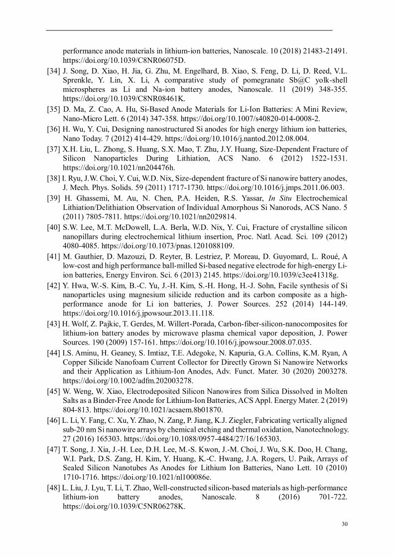
30
performance anode materials in lithium-ion batteries, Nanoscale. 10 (2018) 21483-21491. https://doi.org/10.1039/C8NR06075D.
[34] J. Song, D. Xiao, H. Jia, G. Zhu, M. Engelhard, B. Xiao, S. Feng, D. Li, D. Reed, V.L. Sprenkle, Y. Lin, X. Li, A comparative study of pomegranate Sb@C yolk-shell microspheres as Li and Na-ion battery anodes, Nanoscale. 11 (2019) 348-355. https://doi.org/10.1039/C8NR08461K.
[35] D. Ma, Z. Cao, A. Hu, Si-Based Anode Materials for Li-Ion Batteries: A Mini Review, Nano-Micro Lett. 6 (2014) 347-358. https://doi.org/10.1007/s40820-014-0008-2.
[36] H. Wu, Y. Cui, Designing nanostructured Si anodes for high energy lithium ion batteries, Nano Today. 7 (2012) 414-429. https://doi.org/10.1016/j.nantod.2012.08.004.
[37] X.H. Liu, L. Zhong, S. Huang, S.X. Mao, T. Zhu, J.Y. Huang, Size-Dependent Fracture of Silicon Nanoparticles During Lithiation, ACS Nano. 6 (2012) 1522-1531. https://doi.org/10.1021/nn204476h.
[38] I. Ryu, J.W. Choi, Y. Cui, W.D. Nix, Size-dependent fracture of Si nanowire battery anodes, J. Mech. Phys. Solids. 59 (2011) 1717-1730. https://doi.org/10.1016/j.jmps.2011.06.003.
[39] H. Ghassemi, M. Au, N. Chen, P.A. Heiden, R.S. Yassar, In Situ Electrochemical Lithiation/Delithiation Observation of Individual Amorphous Si Nanorods, ACS Nano. 5 (2011) 7805-7811. https://doi.org/10.1021/nn2029814.
[40] S.W. Lee, M.T. McDowell, L.A. Berla, W.D. Nix, Y. Cui, Fracture of crystalline silicon nanopillars during electrochemical lithium insertion, Proc. Natl. Acad. Sci. 109 (2012) 4080-4085. https://doi.org/10.1073/pnas.1201088109.
[41] M. Gauthier, D. Mazouzi, D. Reyter, B. Lestriez, P. Moreau, D. Guyomard, L. Roué, A low-cost and high performance ball-milled Si-based negative electrode for high-energy Li-ion batteries, Energy Environ. Sci. 6 (2013) 2145. https://doi.org/10.1039/c3ee41318g.
[42] Y. Hwa, W.-S. Kim, B.-C. Yu, J.-H. Kim, S.-H. Hong, H.-J. Sohn, Facile synthesis of Si nanoparticles using magnesium silicide reduction and its carbon composite as a high-performance anode for Li ion batteries, J. Power Sources. 252 (2014) 144-149. https://doi.org/10.1016/j.jpowsour.2013.11.118.
[43] H. Wolf, Z. Pajkic, T. Gerdes, M. Willert-Porada, Carbon-fiber-silicon-nanocomposites for lithium-ion battery anodes by microwave plasma chemical vapor deposition, J. Power Sources. 190 (2009) 157-161. https://doi.org/10.1016/j.jpowsour.2008.07.035.
[44] I.S. Aminu, H. Geaney, S. Imtiaz, T.E. Adegoke, N. Kapuria, G.A. Collins, K.M. Ryan, A Copper Silicide Nanofoam Current Collector for Directly Grown Si Nanowire Networks and their Application as Lithium‐Ion Anodes, Adv. Funct. Mater. 30 (2020) 2003278. https://doi.org/10.1002/adfm.202003278.
[45] W. Weng, W. Xiao, Electrodeposited Silicon Nanowires from Silica Dissolved in Molten Salts as a Binder-Free Anode for Lithium-Ion Batteries, ACS Appl. Energy Mater. 2 (2019) 804-813. https://doi.org/10.1021/acsaem.8b01870.
[46] L. Li, Y. Fang, C. Xu, Y. Zhao, N. Zang, P. Jiang, K.J. Ziegler, Fabricating vertically aligned sub-20 nm Si nanowire arrays by chemical etching and thermal oxidation, Nanotechnology. 27 (2016) 165303. https://doi.org/10.1088/0957-4484/27/16/165303.
[47] T. Song, J. Xia, J.-H. Lee, D.H. Lee, M.-S. Kwon, J.-M. Choi, J. Wu, S.K. Doo, H. Chang, W.I. Park, D.S. Zang, H. Kim, Y. Huang, K.-C. Hwang, J.A. Rogers, U. Paik, Arrays of Sealed Silicon Nanotubes As Anodes for Lithium Ion Batteries, Nano Lett. 10 (2010) 1710-1716. https://doi.org/10.1021/nl100086e.
[48] L. Liu, J. Lyu, T. Li, T. Zhao, Well-constructed silicon-based materials as high-performance lithium-ion battery anodes, Nanoscale. 8 (2016) 701-722. https://doi.org/10.1039/C5NR06278K.

31
[49] Y. Yi, G.-H. Lee, J.-C. Kim, H.-W. Shim, D.-W. Kim, Tailored silicon hollow spheres with Micrococcus for Li ion battery electrodes, Chem. Eng. J. 327 (2017) 297-306. https://doi.org/10.1016/j.cej.2017.06.103.
[50] H. Guo, H. Zhao, C. Yin, W. Qiu, A nanosized silicon thin film as high capacity anode material for Li-ion rechargeable batteries, Mater. Sci. Eng. B. 131 (2006) 173-176. https://doi.org/10.1016/j.mseb.2006.04.008.
[51] C.-M. Hwang, J.-W. Park, Electrochemical characterizations of multi-layer and composite silicon-germanium anodes for Li-ion batteries using magnetron sputtering, J. Power Sources. 196 (2011) 6772-6780. https://doi.org/10.1016/j.jpowsour.2010.10.061.
[52] V. Baranchugov, E. Markevich, E. Pollak, G. Salitra, D. Aurbach, Amorphous silicon thin films as a high capacity anodes for Li-ion batteries in ionic liquid electrolytes, Electrochem. Commun. 9 (2007) 796-800. https://doi.org/10.1016/j.elecom.2006.11.014.
[53] H. Jung, M. Park, S.H. Han, H. Lim, S.-K. Joo, Amorphous silicon thin-film negative electrode prepared by low pressure chemical vapor deposition for lithium-ion batteries, Solid State Commun. 125 (2003) 387-390. https://doi.org/10.1016/S0038-1098(02)00849-9.
[54] A. Mukanova, A. Nurpeissova, A. Urazbayev, S.-S. Kim, M. Myronov, Z. Bakenov, Silicon thin film on graphene coated nickel foam as an anode for Li-ion batteries, Electrochimica Acta. 258 (2017) 800-806. https://doi.org/10.1016/j.electacta.2017.11.129.
[55] Q. Zhang, J. Liu, Z.-Y. Wu, J.-T. Li, L. Huang, S.-G. Sun, 3D nanostructured multilayer Si/Al film with excellent cycle performance as anode material for lithium-ion battery, J. Alloys Compd. 657 (2016) 559-564. https://doi.org/10.1016/j.jallcom.2015.10.123.
[56] W. Sun, R. Hu, M. Zhang, J. Liu, M. Zhu, Binding of carbon coated nano-silicon in graphene sheets by wet ball-milling and pyrolysis as high performance anodes for lithium-ion batteries, J. Power Sources. 318 (2016) 113-120. https://doi.org/10.1016/j.jpowsour.2016.04.016.
[57] X. Tie, Q. Han, C. Liang, B. Li, J. Zai, X. Qian, Si@SiOx/Graphene Nanosheets Composite: Ball Milling Synthesis and Enhanced Lithium Storage Performance, Front. Mater. 4 (2018) 47. https://doi.org/10.3389/fmats.2017.00047.
[58] T. Xu, N. Lin, W. Cai, Z. Yi, J. Zhou, Y. Han, Y. Zhu, Y. Qian, Stabilizing Si/graphite composites with Cu and in situ synthesized carbon nanotubes for high-performance Li-ion battery anodes, Inorg. Chem. Front. 5 (2018) 1463-1469. https://doi.org/10.1039/C8QI00173A.
[59] J.H. Lee, C.S. Yoon, J.-Y. Hwang, S.-J. Kim, F. Maglia, P. Lamp, S.-T. Myung, Y.-K. Sun, High-energy-density lithium-ion battery using a carbon-nanotube-Si composite anode and a compositionally graded Li[Ni0.85Co0.05Mn0.10]O2 cathode, Energy Environ. Sci. 9 (2016) 2152-2158. https://doi.org/10.1039/C6EE01134A.
[60] M.H. Parekh, A.D. Sediako, A. Naseri, M.J. Thomson, V.G. Pol, In Situ Mechanistic Elucidation of Superior Si‐C‐Graphite Li‐Ion Battery Anode Formation with Thermal Safety Aspects, Adv. Energy Mater. 10 (2020) 1902799. https://doi.org/10.1002/aenm.201902799.
[61] J. Liang, X. Li, Y. Zhu, C. Guo, Y. Qian, Hydrothermal synthesis of nano-silicon from a silica sol and its use in lithium ion batteries, Nano Res. 8 (2015) 1497-1504. https://doi.org/10.1007/s12274-014-0633-6.
[62] Q. Zhao, W. Xiao, X. Yan, S. Qin, B. Qu, L. Zhao, Effect of pyrolytic polyacrylonitrile on electrochemical performance of Si/graphite composite anode for lithium-ion batteries, Ionics. 23 (2017) 1685-1692. https://doi.org/10.1007/s11581-017-1992-2.
[63] M. Li, X. Hou, Y. Sha, J. Wang, S. Hu, X. Liu, Z. Shao, Facile spray-drying/pyrolysis synthesis of core-shell structure graphite/silicon-porous carbon composite as a superior

32
anode for Li-ion batteries, J. Power Sources. 248 (2014) 721-728. https://doi.org/10.1016/j.jpowsour.2013.10.012.
[64] W. Weng, C. Zeng, W. Xiao, In Situ Pyrolysis Concerted Formation of Si/C Hybrids during Molten Salt Electrolysis of SiO2@Polydopamine, ACS Appl. Mater. Interfaces. 11 (2019) 9156-9163. https://doi.org/10.1021/acsami.9b00265.
[65] Z. Fan, S. Zheng, S. He, Y. Ye, J. Liang, A. Shi, Z. Wang, Z. Zheng, Preparation of micron Si@C anodes for lithium ion battery by recycling the lamellar submicron silicon in the kerf slurry waste from photovoltaic industry, Diam. Relat. Mater. 107 (2020) 107898. https://doi.org/10.1016/j.diamond.2020.107898.
[66] Y. Li, W. Liu, Z. Long, P. Xu, Y. Sun, X. Zhang, S. Ma, N. Jiang, Si@C Microsphere Composite with Multiple Buffer Structures for High-Performance Lithium-Ion Battery Anodes, Chem. - Eur. J. 24 (2018) 12912-12919. https://doi.org/10.1002/chem.201801417.
[67] J. Liu, Q. Zhang, Z.-Y. Wu, J.-H. Wu, J.-T. Li, L. Huang, S.-G. Sun, A high-performance alginate hydrogel binder for the Si/C anode of a Li-ion battery, Chem. Commun. 50 (2014) 6386. https://doi.org/10.1039/c4cc00081a.
[68] X. Li, Y. Xing, J. Xu, Q. Deng, L.-H. Shao, Uniform yolk-shell structured Si-C nanoparticles as a high performance anode material for the Li-ion battery, Chem. Commun. 56 (2020) 364-367. https://doi.org/10.1039/C9CC07997A.
[69] S. Guo, X. Hu, Y. Hou, Z. Wen, Tunable Synthesis of Yolk-Shell Porous Silicon@Carbon for Optimizing Si/C-Based Anode of Lithium-Ion Batteries, ACS Appl. Mater. Interfaces. 9 (2017) 42084-42092. https://doi.org/10.1021/acsami.7b13035.
[70] L. Hu, B. Luo, C. Wu, P. Hu, L. Wang, H. Zhang, Yolk-shell Si/C composites with multiple Si nanoparticles encapsulated into double carbon shells as lithium-ion battery anodes, J. Energy Chem. 32 (2019) 124-130. https://doi.org/10.1016/j.jechem.2018.07.008.
[71] A.K. Roy, M. Zhong, M.G. Schwab, A. Binder, S.S. Venkataraman, Ž. Tomović, Preparation of a Binder-Free Three-Dimensional Carbon Foam/Silicon Composite as Potential Material for Lithium Ion Battery Anodes, ACS Appl. Mater. Interfaces. 8 (2016) 7343-7348. https://doi.org/10.1021/acsami.5b12026.
[72] Z.-L. Xu, B. Zhang, J.-K. Kim, Electrospun carbon nanofiber anodes containing monodispersed Si nanoparticles and graphene oxide with exceptional high rate capacities, Nano Energy. 6 (2014) 27-35. https://doi.org/10.1016/j.nanoen.2014.03.003.
[73] Y. Liu, H. Zheng, X.H. Liu, S. Huang, T. Zhu, J. Wang, A. Kushima, N.S. Hudak, X. Huang, S. Zhang, S.X. Mao, X. Qian, J. Li, J.Y. Huang, Lithiation-Induced Embrittlement of Multiwalled Carbon Nanotubes, ACS Nano. 5 (2011) 7245-7253. https://doi.org/10.1021/nn202071y.
[74] H. Cho, K. Kim, C.-M. Park, G. Jeong, In situ fabrication of nanohybrid carbon/polyamide film providing robust binding and conductive network in silicon anode for lithium-ion battery, J. Power Sources. 410-411 (2019) 25-30. https://doi.org/10.1016/j.jpowsour.2018.11.005.
[75] R. Shao, J. Niu, F. Zhu, M. Dou, Z. Zhang, F. Wang, A facile and versatile strategy towards high-performance Si anodes for Li-ion capacitors: Concomitant conductive network construction and dual-interfacial engineering, Nano Energy. 63 (2019) 103824. https://doi.org/10.1016/j.nanoen.2019.06.020.
[76] Z. Li, J. Ji, Q. Wu, D. Wei, S. Li, T. Liu, Y. He, Z. Lin, M. Ling, C. Liang, A new battery process technology inspired by partially carbonized polymer binders, Nano Energy. 67 (2020) 104234. https://doi.org/10.1016/j.nanoen.2019.104234.
[77] Q. Hao, J. Hou, J. Ye, H. Yang, J. Du, C. Xu, Hierarchical macroporous Si/Sn composite: Easy preparation and optimized performances towards lithium storage, Electrochimica Acta. 306 (2019) 427-436. https://doi.org/10.1016/j.electacta.2019.03.163.

33
[78] Q. Zhang, H. Chen, L. Luo, B. Zhao, H. Luo, X. Han, J. Wang, C. Wang, Y. Yang, T. Zhu, M. Liu, Harnessing the concurrent reaction dynamics in active Si and Ge to achieve high performance lithium-ion batteries, Energy Environ. Sci. 11 (2018) 669-681. https://doi.org/10.1039/C8EE00239H.
[79] A. Desrues, J.P. Alper, F. Boismain, D. Zapata Dominguez, C. Berhaut, P. Coulon, A. Soloy, F. Grisch, S. Tardif, S. Pouget, S. Lyonnard, C. Haon, N. Herlin‐Boime, Best Performing SiGe/Si Core‐Shell Nanoparticles Synthesized in One Step for High Capacity Anodes, Batter. Supercaps. 2 (2019) 970-978. https://doi.org/10.1002/batt.201900094.
[80] N.-S. Choi, Y. Yao, Y. Cui, J. Cho, One dimensional Si/Sn - based nanowires and nanotubes for lithium-ion energy storage materials, J. Mater. Chem. 21 (2011) 9825. https://doi.org/10.1039/c0jm03842c.
[81] Z. Edfouf, F. Cuevas, M. Latroche, C. Georges, C. Jordy, T. Hézèque, G. Caillon, J.C. Jumas, M.T. Sougrati, Nanostructured Si/Sn-Ni/C composite as negative electrode for Li-ion batteries, J. Power Sources. 196 (2011) 4762-4768. https://doi.org/10.1016/j.jpowsour.2011.01.046.
[82] S. Wang, T. Wang, Y. Zhong, Q. Deng, Y. Mao, G. Wang, Structure and Electrochemical Properties of Si-Mn/C Core-Shell Composites for Lithium-Ion Batteries, JOM. 72 (2020) 3037-3045. https://doi.org/10.1007/s11837-020-04214-4.
[83] L. Deng, Z.-Y. Wu, Z.-W. Yin, Y.-Q. Lu, Z.-G. Huang, J.-H. You, J.-T. Li, L. Huang, S.-G. Sun, High-performance Si Mn/C composite anodes with integrating inactive Mn4Si7 alloy for lithium-ion batteries, Electrochimica Acta. 260 (2018) 830-837. https://doi.org/10.1016/j.electacta.2017.12.048.
[84] L. Lin, Y. Ma, Q. Xie, L. Wang, Q. Zhang, D.-L. Peng, Copper-Nanoparticle-Induced Porous Si/Cu Composite Films as an Anode for Lithium Ion Batteries, ACS Nano. 11 (2017) 6893-6903. https://doi.org/10.1021/acsnano.7b02030.
[85] N. Fukata, M. Mitome, Y. Bando, W. Wu, Z.L. Wang, Lithium ion battery anodes using Si-Fe based nanocomposite structures, Nano Energy. 26 (2016) 37-42. https://doi.org/10.1016/j.nanoen.2016.05.007.
[86] C. Fang, X. Wang, Y.S. Meng, Key Issues Hindering a Practical Lithium-Metal Anode, Trends Chem. 1 (2019) 152-158. https://doi.org/10.1016/j.trechm.2019.02.015.
[87] R. Xu, X.-B. Cheng, C. Yan, X.-Q. Zhang, Y. Xiao, C.-Z. Zhao, J.-Q. Huang, Q. Zhang, Artificial Interphases for Highly Stable Lithium Metal Anode, Matter. 1 (2019) 317-344. https://doi.org/10.1016/j.matt.2019.05.016.
[88] K. Yan, H.-W. Lee, T. Gao, G. Zheng, H. Yao, H. Wang, Z. Lu, Y. Zhou, Z. Liang, Z. Liu, S. Chu, Y. Cui, Ultrathin Two-Dimensional Atomic Crystals as Stable Interfacial Layer for Improvement of Lithium Metal Anode, Nano Lett. 14 (2014) 6016-6022. https://doi.org/10.1021/nl503125u.
[89] F. Liu, Q. Xiao, H.B. Wu, L. Shen, D. Xu, M. Cai, Y. Lu, Fabrication of Hybrid Silicate Coatings by a Simple Vapor Deposition Method for Lithium Metal Anodes, Adv. Energy Mater. 8 (2018) 1701744. https://doi.org/10.1002/aenm.201701744.
[90] N.-W. Li, Y. Shi, Y.-X. Yin, X.-X. Zeng, J.-Y. Li, C.-J. Li, L.-J. Wan, R. Wen, Y.-G. Guo, A Flexible Solid Electrolyte Interphase Layer for Long-Life Lithium Metal Anodes, Angew. Chem. 130 (2018) 1521-1525. https://doi.org/10.1002/ange.201710806.
[91] X. Liang, Q. Pang, I.R. Kochetkov, M.S. Sempere, H. Huang, X. Sun, L.F. Nazar, A facile surface chemistry route to a stabilized lithium metal anode, Nat. Energy. 2 (2017) 17119. https://doi.org/10.1038/nenergy.2017.119.
[92] C. Yan, X.-B. Cheng, Y.-X. Yao, X. Shen, B.-Q. Li, W.-J. Li, R. Zhang, J.-Q. Huang, H. Li, Q. Zhang, An Armored Mixed Conductor Interphase on a Dendrite-Free Lithium-Metal Anode, Adv. Mater. 30 (2018) 1804461. https://doi.org/10.1002/adma.201804461.

34
[93] N.-W. Li, Y.-X. Yin, C.-P. Yang, Y.-G. Guo, An Artificial Solid Electrolyte Interphase Layer for Stable Lithium Metal Anodes, Adv. Mater. 28 (2016) 1853-1858. https://doi.org/10.1002/adma.201504526.
[94] Y. Liu, D. Lin, P.Y. Yuen, K. Liu, J. Xie, R.H. Dauskardt, Y. Cui, An Artificial Solid Electrolyte Interphase with High Li-Ion Conductivity, Mechanical Strength, and Flexibility for Stable Lithium Metal Anodes, Adv. Mater. 29 (2017) 1605531. https://doi.org/10.1002/adma.201605531.
[95] S.-J. Zhang, Z.-G. Gao, W.-W. Wang, Y.-Q. Lu, Y.-P. Deng, J.-H. You, J.-T. Li, Y. Zhou, L. Huang, X.-D. Zhou, S.-G. Sun, A Natural Biopolymer Film as a Robust Protective Layer to Effectively Stabilize Lithium-Metal Anodes, Small. 14 (2018) 1801054. https://doi.org/10.1002/smll.201801054.
[96] A. Magasinski, B. Zdyrko, I. Kovalenko, B. Hertzberg, R. Burtovyy, C.F. Huebner, T.F. Fuller, I. Luzinov, G. Yushin, Toward Efficient Binders for Li-Ion Battery Si-Based Anodes: Polyacrylic Acid, ACS Appl. Mater. Interfaces. 2 (2010) 3004-3010. https://doi.org/10.1021/am100871y.
[97] Z.-J. Han, K. Yamagiwa, N. Yabuuchi, J.-Y. Son, Y.-T. Cui, H. Oji, A. Kogure, T. Harada, S. Ishikawa, Y. Aoki, S. Komaba, Electrochemical lithiation performance and characterization of silicon-graphite composites with lithium, sodium, potassium, and ammonium polyacrylate binders, Phys. Chem. Chem. Phys. 17 (2015) 3783-3795. https://doi.org/10.1039/C4CP04939J.
[98] T.M. Higgins, S.-H. Park, P.J. King, C. (John) Zhang, N. McEvoy, N.C. Berner, D. Daly, A. Shmeliov, U. Khan, G. Duesberg, V. Nicolosi, J.N. Coleman, A Commercial Conducting Polymer as Both Binder and Conductive Additive for Silicon Nanoparticle-Based Lithium-Ion Battery Negative Electrodes, ACS Nano. 10 (2016) 3702-3713. https://doi.org/10.1021/acsnano.6b00218.
[99] S. Uchida, M. Mihashi, M. Yamagata, M. Ishikawa, Electrochemical properties of non-nano-silicon negative electrodes prepared with a polyimide binder, J. Power Sources. 273 (2015) 118-122. https://doi.org/10.1016/j.jpowsour.2014.09.096.
[100] L. Luo, Y. Xu, H. Zhang, X. Han, H. Dong, X. Xu, C. Chen, Y. Zhang, J. Lin, Comprehensive Understanding of High Polar Polyacrylonitrile as an Effective Binder for Li-Ion Battery Nano-Si Anodes, ACS Appl. Mater. Interfaces. 8 (2016) 8154-8161. https://doi.org/10.1021/acsami.6b03046.
[101] X. Yu, H. Yang, H. Meng, Y. Sun, J. Zheng, D. Ma, X. Xu, Three-Dimensional Conductive Gel Network as an Effective Binder for High-Performance Si Electrodes in Lithium-Ion Batteries, ACS Appl. Mater. Interfaces. 7 (2015) 15961-15967. https://doi.org/10.1021/acsami.5b04058.
[102] X. He, R. Han, P. Jiang, Y. Chen, W. Liu, Molecularly Engineered Conductive Polymer Binder Enables Stable Lithium Storage of Si, Ind. Eng. Chem. Res. 59 (2020) 2680-2688. https://doi.org/10.1021/acs.iecr.9b05838.
[103] M. Zheng, C. Wang, Y. Xu, K. Li, D. Liu, A water-soluble binary conductive binder for Si anode lithium ion battery, Electrochimica Acta. 305 (2019) 555-562. https://doi.org/10.1016/j.electacta.2019.02.080.
[104] D. Mazouzi, B. Lestriez, L. Roué, D. Guyomard, Silicon Composite Electrode with High Capacity and Long Cycle Life, Electrochem. Solid-State Lett. 12 (2009) A215. https://doi.org/10.1149/1.3212894.
[105] I. Kovalenko, B. Zdyrko, A. Magasinski, B. Hertzberg, Z. Milicev, R. Burtovyy, I. Luzinov, G. Yushin, A Major Constituent of Brown Algae for Use in High-Capacity Li-Ion Batteries, Science. 334 (2011) 75-79. https://doi.org/10.1126/science.1209150.
[106] Y.K. Jeong, T. Kwon, I. Lee, T.-S. Kim, A. Coskun, J.W. Choi, Hyperbranched β-

35
Cyclodextrin Polymer as an Effective Multidimensional Binder for Silicon Anodes in Lithium Rechargeable Batteries, Nano Lett. 14 (2014) 864-870. https://doi.org/10.1021/nl404237j.
[107] M. Ling, Y. Xu, H. Zhao, X. Gu, J. Qiu, S. Li, M. Wu, X. Song, C. Yan, G. Liu, S. Zhang, Dual-functional gum arabic binder for silicon anodes in lithium ion batteries, Nano Energy. 12 (2015) 178-185. https://doi.org/10.1016/j.nanoen.2014.12.011.
[108] Y.K. Jeong, T. Kwon, I. Lee, T.-S. Kim, A. Coskun, J.W. Choi, Millipede-inspired structural design principle for high performance polysaccharide binders in silicon anodes, Energy Environ. Sci. 8 (2015) 1224-1230. https://doi.org/10.1039/C5EE00239G.
[109] J. Liu, Q. Zhang, T. Zhang, J.-T. Li, L. Huang, S.-G. Sun, A Robust Ion-Conductive Biopolymer as a Binder for Si Anodes of Lithium-Ion Batteries, Adv. Funct. Mater. 25 (2015) 3599-3605. https://doi.org/10.1002/adfm.201500589.
[110] L. Yue, L. Zhang, H. Zhong, Carboxymethyl chitosan: A new water soluble binder for Si anode of Li-ion batteries, J. Power Sources. 247 (2014) 327-331. https://doi.org/10.1016/j.jpowsour.2013.08.073.
[111] S. Klamor, M. Schröder, G. Brunklaus, P. Niehoff, F. Berkemeier, F.M. Schappacher, M. Winter, On the interaction of water-soluble binders and nano silicon particles: alternative binder towards increased cycling stability at elevated temperatures, Phys. Chem. Chem. Phys. 17 (2015) 5632-5641. https://doi.org/10.1039/C4CP04090B.
[112] Y. Bie, J. Yang, Y. Nuli, J. Wang, Natural karaya gum as an excellent binder for silicon-based anodes in high-performance lithium-ion batteries, J. Mater. Chem. A. 5 (2017) 1919-1924. https://doi.org/10.1039/C6TA09522D.
[113] S. Guo, H. Li, Y. Li, Y. Han, K. Chen, G. Xu, Y. Zhu, X. Hu, SiO2 ‐Enhanced Structural Stability and Strong Adhesion with a New Binder of Konjac Glucomannan Enables Stable Cycling of Silicon Anodes for Lithium‐Ion Batteries, Adv. Energy Mater. 8 (2018) 1800434. https://doi.org/10.1002/aenm.201800434.
[114] D. Choi, K.L. Choy, Spider silk binder for Si-based anode in lithium-ion batteries, Mater. Des. 191 (2020) 108669. https://doi.org/10.1016/j.matdes.2020.108669.
[115] M.-H. Ryou, J. Kim, I. Lee, S. Kim, Y.K. Jeong, S. Hong, J.H. Ryu, T.-S. Kim, J.-K. Park, H. Lee, J.W. Choi, Mussel-Inspired Adhesive Binders for High-Performance Silicon Nanoparticle Anodes in Lithium-Ion Batteries, Adv. Mater. 25 (2013) 1571-1576. https://doi.org/10.1002/adma.201203981.
[116] P.-F. Cao, G. Yang, B. Li, Y. Zhang, S. Zhao, S. Zhang, A. Erwin, Z. Zhang, A.P. Sokolov, J. Nanda, T. Saito, Rational Design of a Multifunctional Binder for High-Capacity Silicon-Based Anodes, ACS Energy Lett. 4 (2019) 1171-1180. https://doi.org/10.1021/acsenergylett.9b00815.
[117] Z.-Y. Wu, L. Deng, J.-T. Li, Q.-S. Huang, Y.-Q. Lu, J. Liu, T. Zhang, L. Huang, S.-G. Sun, Multiple hydrogel alginate binders for Si anodes of lithium-ion battery, Electrochimica Acta. 245 (2017) 371-378. https://doi.org/10.1016/j.electacta.2017.05.094.
[118] Y. Gu, S. Yang, G. Zhu, Y. Yuan, Q. Qu, Y. Wang, H. Zheng, The effects of cross-linking cations on the electrochemical behavior of silicon anodes with alginate binder, Electrochimica Acta. 269 (2018) 405-414. https://doi.org/10.1016/j.electacta.2018.02.168.
[119] W. Zeng, L. Wang, X. Peng, T. Liu, Y. Jiang, F. Qin, L. Hu, P.K. Chu, K. Huo, Y. Zhou, Enhanced Ion Conductivity in Conducting Polymer Binder for High-Performance Silicon Anodes in Advanced Lithium-Ion Batteries, Adv. Energy Mater. 8 (2018) 1702314. https://doi.org/10.1002/aenm.201702314.
[120] Q. Ye, P. Zheng, X. Ao, D. Yao, Z. Lei, Y. Deng, C. Wang, Novel multi-block conductive binder with polybutadiene for Si anodes in lithium-ion batteries, Electrochimica Acta. 315 (2019) 58-66. https://doi.org/10.1016/j.electacta.2019.05.093.

36
[121] Y. Zhao, L. Yang, Y. Zuo, Z. Song, F. Liu, K. Li, F. Pan, Conductive Binder for Si Anode with Boosted Charge Transfer Capability via n-Type Doping, ACS Appl. Mater. Interfaces. 10 (2018) 27795-27800. https://doi.org/10.1021/acsami.8b08843.
[122] T. Liu, Q. Chu, C. Yan, S. Zhang, Z. Lin, J. Lu, Interweaving 3D Network Binder for High-Areal-Capacity Si Anode through Combined Hard and Soft Polymers, Adv. Energy Mater. 9 (2019) 1802645. https://doi.org/10.1002/aenm.201802645.
[123] G. Zhang, Y. Yang, Y. Chen, J. Huang, T. Zhang, H. Zeng, C. Wang, G. Liu, Y. Deng, A Quadruple-Hydrogen-Bonded Supramolecular Binder for High-Performance Silicon Anodes in Lithium-Ion Batteries, Small. 14 (2018) 1801189. https://doi.org/10.1002/smll.201801189.
[124] J. Li, G. Zhang, Y. Yang, D. Yao, Z. Lei, S. Li, Y. Deng, C. Wang, Glycinamide modified polyacrylic acid as high-performance binder for silicon anodes in lithium-ion batteries, J. Power Sources. 406 (2018) 102-109. https://doi.org/10.1016/j.jpowsour.2018.10.057.
[125] S. Kim, Y.K. Jeong, Y. Wang, H. Lee, J.W. Choi, A “Sticky” Mucin-Inspired DNA-Polysaccharide Binder for Silicon and Silicon-Graphite Blended Anodes in Lithium-Ion Batteries, Adv. Mater. 30 (2018) 1707594. https://doi.org/10.1002/adma.201707594.
[126] Y. Cai, Y. Li, B. Jin, A. Ali, M. Ling, D. Cheng, J. Lu, Y. Hou, Q. He, X. Zhan, F. Chen, Q. Zhang, Dual Cross-Linked Fluorinated Binder Network for High-Performance Silicon and Silicon Oxide Based Anodes in Lithium-Ion Batteries, ACS Appl. Mater. Interfaces. 11 (2019) 46800-46807. https://doi.org/10.1021/acsami.9b16387.
[127] C. Wang, H. Wu, Z. Chen, M.T. McDowell, Y. Cui, Z. Bao, Self-healing chemistry enables the stable operation of silicon microparticle anodes for high-energy lithium-ion batteries, Nat. Chem. 5 (2013) 1042-1048. https://doi.org/10.1038/nchem.1802.
[128] T. Munaoka, X. Yan, J. Lopez, J.W.F. To, J. Park, J.B.-H. Tok, Y. Cui, Z. Bao, Ionically Conductive Self-Healing Binder for Low Cost Si Microparticles Anodes in Li-Ion Batteries, Adv. Energy Mater. 8 (2018) 1703138. https://doi.org/10.1002/aenm.201703138.
[129] S. Choi, T. Kwon, A. Coskun, J.W. Choi, Highly elastic binders integrating polyrotaxanes for silicon microparticle anodes in lithium ion batteries, Science. 357 (2017) 279-283. https://doi.org/10.1126/science.aal4373.
[130] C. Luo, L. Du, W. Wu, H. Xu, G. Zhang, S. Li, C. Wang, Z. Lu, Y. Deng, Novel Lignin-Derived Water-Soluble Binder for Micro Silicon Anode in Lithium-Ion Batteries, ACS Sustain. Chem. Eng. 6 (2018) 12621-12629. https://doi.org/10.1021/acssuschemeng.8b01161.
[131] Z. Xu, J. Yang, T. Zhang, Y. Nuli, J. Wang, S. Hirano, Silicon Microparticle Anodes with Self-Healing Multiple Network Binder, Joule. 2 (2018) 950-961. https://doi.org/10.1016/j.joule.2018.02.012.
[132] J. He, H. Zhong, J. Wang, L. Zhang, Investigation on xanthan gum as novel water soluble binder for LiFePO 4 cathode in lithium-ion batteries, J. Alloys Compd. 714 (2017) 409-418. https://doi.org/10.1016/j.jallcom.2017.04.238.
[133] Y. Zhao, L. Yang, D. Liu, J. Hu, L. Han, Z. Wang, F. Pan, A Conductive Binder for High-Performance Sn Electrodes in Lithium-Ion Batteries, ACS Appl. Mater. Interfaces. 10 (2018) 1672-1677. https://doi.org/10.1021/acsami.7b13692.
[134] S.-L. Chou, X.-W. Gao, J.-Z. Wang, D. Wexler, Z.-X. Wang, L.-Q. Chen, H.-K. Liu, Tin/polypyrrole composite anode using sodium carboxymethyl cellulose binder for lithium-ion batteries, Dalton Trans. 40 (2011) 12801. https://doi.org/10.1039/c1dt10396b.
[135] M. Sun, H. Zhong, S. Jiao, H. Shao, L. Zhang, Investigation on Carboxymethyl Chitosan as New Water Soluble Binder for LiFePO4 Cathode in Li-Ion Batteries, Electrochimica Acta. 127 (2014) 239-244. https://doi.org/10.1016/j.electacta.2014.02.027.
[136] S. Hu, Y. Li, J. Yin, H. Wang, X. Yuan, Q. Li, Effect of different binders on

37
electrochemical properties of LiFePO4/C cathode material in lithium ion batteries, Chem. Eng. J. 237 (2014) 497-502. https://doi.org/10.1016/j.cej.2013.08.119.
[137] J. Liu, D.G.D. Galpaya, L. Yan, M. Sun, Z. Lin, C. Yan, C. Liang, S. Zhang, Exploiting a robust biopolymer network binder for an ultrahigh-areal-capacity Li-S battery, Energy Environ. Sci. 10 (2017) 750-755. https://doi.org/10.1039/C6EE03033E.
[138] C.Y. Kwok, Q. Pang, A. Worku, X. Liang, M. Gauthier, L.F. Nazar, Impact of the Mechanical Properties of a Functionalized Cross-Linked Binder on the Longevity of Li-S Batteries, ACS Appl. Mater. Interfaces. 11 (2019) 22481-22491. https://doi.org/10.1021/acsami.9b06456.
[139] Y. Mo, Y. Wu, Z. Yin, W. Ren, Z. Gao, P. Zhang, J. Lin, Y. Zhou, J. Li, L. Huang, S. Sun, High Cycling Performance Li‐S Battery via Fenugreek Gum Binder Through Chemical Bonding of the Binder with Polysulfides in Nanosulfur@CNFs Cathode, ChemistrySelect. 5 (2020) 8969-8979. https://doi.org/10.1002/slct.202002471.
[140] Y.-Q. Lu, J.-T. Li, X.-X. Peng, T. Zhang, Y.-P. Deng, Z.-Y. Wu, L. Deng, L. Huang, X.-D. Zhou, S.-G. Sun, Achieving high capacity retention in lithium-sulfur batteries with an aqueous binder, Electrochem. Commun. 72 (2016) 79-82. https://doi.org/10.1016/j.elecom.2016.09.004.
[141] S. Kim, M. Cho, Y. Lee, Saponin-containing multifunctional binder toward superior long-term cycling stability in Li-S batteries, J. Mater. Chem. A. 8 (2020) 10419-10425. https://doi.org/10.1039/D0TA03051A.
[142] H.Q. Pham, G. Kim, H.M. Jung, S.-W. Song, Fluorinated Polyimide as a Novel High-Voltage Binder for High-Capacity Cathode of Lithium-Ion Batteries, Adv. Funct. Mater. 28 (2018) 1704690. https://doi.org/10.1002/adfm.201704690.
[143] S.-J. Zhang, Y.-P. Deng, Q.-H. Wu, Y. Zhou, J.-T. Li, Z.-Y. Wu, Z.-W. Yin, Y.-Q. Lu, C.-H. Shen, L. Huang, S.-G. Sun, Sodium-Alginate-Based Binders for Lithium-Rich Cathode Materials in Lithium-Ion Batteries to Suppress Voltage and Capacity Fading, ChemElectroChem. 5 (2018) 1321-1329. https://doi.org/10.1002/celc.201701358.
[144] Z.-W. Yin, T. Zhang, S.-J. Zhang, Y.-P. Deng, X.-X. Peng, J.-Q. Wang, J.-T. Li, L. Huang, H. Zheng, S.-G. Sun, Understanding the role of water-soluble guar gum binder in reducing capacity fading and voltage decay of Li-rich cathode for Li-ion batteries, Electrochimica Acta. 351 (2020) 136401. https://doi.org/10.1016/j.electacta.2020.136401.
[145] T. Zhang, J. Li, J. Liu, Y. Deng, Z. Wu, Z. Yin, D. Guo, L. Huang, S. Sun, Suppressing the voltage-fading of layered lithium-rich cathode materials via an aqueous binder for Li-ion batteries, Chem. Commun. 52 (2016) 4683-4686. https://doi.org/10.1039/C5CC10534J.
[146] Y. Ma, K. Chen, J. Ma, G. Xu, S. Dong, B. Chen, J. Li, Z. Chen, X. Zhou, G. Cui, A biomass based free radical scavenger binder endowing a compatible cathode interface for 5 V lithium-ion batteries, Energy Environ. Sci. 12 (2019) 273-280. https://doi.org/10.1039/C8EE02555J.
[147] M. Marcinek, J. Syzdek, M. Marczewski, M. Piszcz, L. Niedzicki, M. Kalita, A. Plewa-Marczewska, A. Bitner, P. Wieczorek, T. Trzeciak, M. Kasprzyk, P.Łężak, Z. Zukowska, A. Zalewska, W. Wieczorek, Electrolytes for Li-ion transport - Review, Solid State Ion. 276 (2015) 107-126. https://doi.org/10.1016/j.ssi.2015.02.006.
[148] E. Peled, S. Menkin, Review—SEI: Past, Present and Future, J. Electrochem. Soc. 164 (2017) A1703-A1719. https://doi.org/10.1149/2.1441707jes.
[149] K. Xu, A. von Cresce, Interfacing electrolytes with electrodes in Li ion batteries, J. Mater. Chem. 21 (2011) 9849. https://doi.org/10.1039/c0jm04309e.
[150] M. Herstedt, H. Rensmo, H. Siegbahn, K. Edström, Electrolyte additives for enhanced thermal stability of the graphite anode interface in a Li-ion battery, Electrochimica Acta.

38
49 (2004) 2351-2359. https://doi.org/10.1016/j.electacta.2004.01.016. [151] Q. Huang, T. Wang, M. Yan, Z. Jiang, Ammonium Perfluorocaprylate: An Electrolyte
Additive for Lithium-Ion Batteries with Carbonaceous Anodes, J. Electrochem. Soc. 153 (2006) A2363. https://doi.org/10.1149/1.2359693.
[152] C.-C. Chang, S.-H. Hsu, Y.-F. Jung, C.-H. Yang, Vinylene carbonate and vinylene trithiocarbonate as electrolyte additives for lithium ion battery, J. Power Sources. 196 (2011) 9605-9611. https://doi.org/10.1016/j.jpowsour.2011.06.058.
[153] W. Li, B.L. Lucht, Inhibition of the Detrimental Effects of Water Impurities in Lithium-Ion Batteries, Electrochem. Solid-State Lett. 10 (2007) A115. https://doi.org/10.1149/1.2458913.
[154] F.-M. Wang, M.-H. Yu, C.-S. Cheng, S.A. Pradanawati, S.-C. Lo, J. Rick, Phenylenedimaleimide positional isomers used as lithium ion battery electrolyte additives: Relating physical and electrochemical characterization to battery performance, J. Power Sources. 231 (2013) 18-22. https://doi.org/10.1016/j.jpowsour.2012.12.093.
[155] L. Chen, K. Wang, X. Xie, J. Xie, Effect of vinylene carbonate (VC) as electrolyte additive on electrochemical performance of Si film anode for lithium ion batteries, J. Power Sources. 174 (2007) 538-543. https://doi.org/10.1016/j.jpowsour.2007.06.149.
[156] N.-S. Choi, K.H. Yew, K.Y. Lee, M. Sung, H. Kim, S.-S. Kim, Effect of fluoroethylene carbonate additive on interfacial properties of silicon thin-film electrode, J. Power Sources. 161 (2006) 1254-1259. https://doi.org/10.1016/j.jpowsour.2006.05.049.
[157] V. Etacheri, O. Haik, Y. Goffer, G.A. Roberts, I.C. Stefan, R. Fasching, D. Aurbach, Effect of Fluoroethylene Carbonate (FEC) on the Performance and Surface Chemistry of Si-Nanowire Li-Ion Battery Anodes, Langmuir. 28 (2012) 965-976. https://doi.org/10.1021/la203712s.
[158] Y.-M. Lin, K.C. Klavetter, P.R. Abel, N.C. Davy, J.L. Snider, A. Heller, C.B. Mullins, High performance silicon nanoparticle anode in fluoroethylene carbonate-based electrolyte for Li-ion batteries, Chem. Commun. 48 (2012) 7268. https://doi.org/10.1039/c2cc31712e.
[159] I.A. Profatilova, C. Stock, A. Schmitz, S. Passerini, M. Winter, Enhanced thermal stability of a lithiated nano-silicon electrode by fluoroethylene carbonate and vinylene carbonate, J. Power Sources. 222 (2013) 140-149. https://doi.org/10.1016/j.jpowsour.2012.08.066.
[160] G.-B. Han, M.-H. Ryou, K.Y. Cho, Y.M. Lee, J.-K. Park, Effect of succinic anhydride as an electrolyte additive on electrochemical characteristics of silicon thin-film electrode, J. Power Sources. 195 (2010) 3709-3714. https://doi.org/10.1016/j.jpowsour.2009.11.142.
[161] Y. Li, G. Xu, Y. Yao, L. Xue, S. Zhang, Y. Lu, O. Toprakci, X. Zhang, Improvement of cyclability of silicon-containing carbon nanofiber anodes for lithium-ion batteries by employing succinic anhydride as an electrolyte additive, J. Solid State Electrochem. 17 (2013) 1393-1399. https://doi.org/10.1007/s10008-013-2005-7.
[162] N.-S. Choi, K.H. Yew, H. Kim, S.-S. Kim, W.-U. Choi, Surface layer formed on silicon thin-film electrode in lithium bis(oxalato) borate-based electrolyte, J. Power Sources. 172 (2007) 404-409. https://doi.org/10.1016/j.jpowsour.2007.07.058.
[163] G.-B. Han, J.-N. Lee, J.W. Choi, J.-K. Park, Tris(pentafluorophenyl) borane as an electrolyte additive for high performance silicon thin film electrodes in lithium ion batteries, Electrochimica Acta. 56 (2011) 8997-9003. https://doi.org/10.1016/j.electacta.2011.07.136.
[164] T. Jaumann, J. Balach, M. Klose, S. Oswald, J. Eckert, L. Giebeler, Role of 1,3-Dioxolane and LiNO3 Addition on the Long Term Stability of Nanostructured Silicon/Carbon Anodes for Rechargeable Lithium Batteries, J. Electrochem. Soc. 163 (2016) A557-A564. https://doi.org/10.1149/2.1011603jes.

39
[165] S. Dalavi, P. Guduru, B.L. Lucht, Performance Enhancing Electrolyte Additives for Lithium Ion Batteries with Silicon Anodes, J. Electrochem. Soc. 159 (2012) A642. https://doi.org/10.1149/2.076205jes.
[166] T. Takamura, M. Uehara, J. Suzuki, K. Sekine, K. Tamura, High capacity and long cycle life silicon anode for Li-ion battery, J. Power Sources. 158 (2006) 1401-1404. https://doi.org/10.1016/j.jpowsour.2005.10.081.
[167] V. Etacheri, U. Geiger, Y. Gofer, G.A. Roberts, I.C. Stefan, R. Fasching, D. Aurbach, Exceptional Electrochemical Performance of Si-Nanowires in 1,3-Dioxolane Solutions: A Surface Chemical Investigation, Langmuir. 28 (2012) 6175-6184. https://doi.org/10.1021/la300306v.
[168] C. Li, Y. Chen, Y. Chen, B. Lao, L. Qi, H. Wang, Stability analysis for 5V high energy density pouch batteries of Si anode and SL/EMC electrolytes, J. Alloys Compd. 773 (2019) 105-111. https://doi.org/10.1016/j.jallcom.2018.09.249.
[169] M.N. Obrovac, L. Christensen, Structural Changes in Silicon Anodes during Lithium Insertion/Extraction, Electrochem. Solid-State Lett. 7 (2004) A93. https://doi.org/10.1149/1.1652421.
[170] W. Xu, S.S.S. Vegunta, J.C. Flake, Surface-modified silicon nanowire anodes for lithium-ion batteries, J. Power Sources. 196 (2011) 8583-8589. https://doi.org/10.1016/j.jpowsour.2011.05.059.
[171] C. Pereira-Nabais, J. Światowska, A. Chagnes, F. Ozanam, A. Gohier, P. Tran-Van, C.-S. Cojocaru, M. Cassir, P. Marcus, Interphase chemistry of Si electrodes used as anodes in Li-ion batteries, Appl. Surf. Sci. 266 (2013) 5-16. https://doi.org/10.1016/j.apsusc.2012.10.165.
[172] D. Aurbach, H. Gottlieb, The electrochemical behavior of selected polar aprotic systems, Electrochimica Acta. 34 (1989) 141-156. https://doi.org/10.1016/0013-4686(89)87079-3.
[173] X. Wang, E. Yasukawa, S. Mori, Electrochemical Behavior of Lithium Imide/Cyclic Ether Electrolytes for 4 V Lithium Metal Rechargeable Batteries, J. Electrochem. Soc. 146 (1999) 3992-3998. https://doi.org/10.1149/1.1392581.
[174] J.-G. Zhang, W. Xu, W.A. Henderson, Lithium Metal Anodes and Rechargeable Lithium Metal Batteries, Springer International Publishing, Cham, 2017. https://doi.org/10.1007/978-3-319-44054-5.
[175] W. Xu, J. Wang, F. Ding, X. Chen, E. Nasybulin, Y. Zhang, J.-G. Zhang, Lithium metal anodes for rechargeable batteries, Energy Env. Sci. 7 (2014) 513-537. https://doi.org/10.1039/C3EE40795K.
[176] F. Ding, W. Xu, X. Chen, J. Zhang, M.H. Engelhard, Y. Zhang, B.R. Johnson, J.V. Crum, T.A. Blake, X. Liu, J.-G. Zhang, Effects of Carbonate Solvents and Lithium Salts on Morphology and Coulombic Efficiency of Lithium Electrode, J. Electrochem. Soc. 160 (2013) A1894-A1901. https://doi.org/10.1149/2.100310jes.
[177] J. Qian, W.A. Henderson, W. Xu, P. Bhattacharya, M. Engelhard, O. Borodin, J.-G. Zhang, High rate and stable cycling of lithium metal anode, Nat. Commun. 6 (2015) 6362. https://doi.org/10.1038/ncomms7362.
[178] R. Miao, J. Yang, Z. Xu, J. Wang, Y. Nuli, L. Sun, A new ether-based electrolyte for dendrite-free lithium-metal based rechargeable batteries, Sci. Rep. 6 (2016) 21771. https://doi.org/10.1038/srep21771.
[179] H. Ota, K. Shima, M. Ue, J. Yamaki, Effect of vinylene carbonate as additive to electrolyte for lithium metal anode, Electrochimica Acta. 49 (2004) 565-572. https://doi.org/10.1016/j.electacta.2003.09.010.
[180] Y. Qian, C. Schultz, P. Niehoff, T. Schwieters, S. Nowak, F.M. Schappacher, M. Winter, Investigations on the electrochemical decomposition of the electrolyte additive vinylene

40
carbonate in Li metal half cells and lithium ion full cells, J. Power Sources. 332 (2016) 60-71. https://doi.org/10.1016/j.jpowsour.2016.09.100.
[181] X.-Q. Zhang, X.-B. Cheng, X. Chen, C. Yan, Q. Zhang, Fluoroethylene Carbonate Additives to Render Uniform Li Deposits in Lithium Metal Batteries, Adv. Funct. Mater. 27 (2017) 1605989. https://doi.org/10.1002/adfm.201605989.
[182] K. Nishikawa, Y. Fukunaka, T. Sakka, Y.H. Ogata, J.R. Selman, Measurement of Concentration Profiles during Electrodeposition of Li Metal from LiPF[sub 6]-PC Electrolyte Solution, J. Electrochem. Soc. 154 (2007) A943. https://doi.org/10.1149/1.2767404.
[183] V. Nilsson, A. Kotronia, M. Lacey, K. Edström, P. Johansson, Highly Concentrated LiTFSI-EC Electrolytes for Lithium Metal Batteries, ACS Appl. Energy Mater. 3 (2020) 200-207. https://doi.org/10.1021/acsaem.9b01203.
[184] H. Saruwatari, T. Kuboki, T. Kishi, S. Mikoshiba, N. Takami, Imidazolium ionic liquids containing LiBOB electrolyte for lithium battery, J. Power Sources. 195 (2010) 1495-1499. https://doi.org/10.1016/j.jpowsour.2009.08.081.
[185] D. Aurbach, Y. Cohen, Morphological Studies of Li Deposition Processes in LiAsF6 / PC Solutions by In Situ Atomic Force Microscopy, J. Electrochem. Soc. 144 (1997) 3355-3360. https://doi.org/10.1149/1.1838018.
[186] H. Xiang, P. Shi, P. Bhattacharya, X. Chen, D. Mei, M.E. Bowden, J. Zheng, J.-G. Zhang, W. Xu, Enhanced charging capability of lithium metal batteries based on lithium bis(trifluoromethanesulfonyl)imide-lithium bis(oxalato)borate dual-salt electrolytes, J. Power Sources. 318 (2016) 170-177. https://doi.org/10.1016/j.jpowsour.2016.04.017.
[187] H. Zheng, H. Xiang, F. Jiang, Y. Liu, Y. Sun, X. Liang, Y. Feng, Y. Yu, Lithium Difluorophosphate‐Based Dual‐Salt Low Concentration Electrolytes for Lithium Metal Batteries, Adv. Energy Mater. 10 (2020) 2001440. https://doi.org/10.1002/aenm.202001440.
[188] T.T. Beyene, H.K. Bezabh, M.A. Weret, T.M. Hagos, C.-J. Huang, C.-H. Wang, W.-N. Su, H. Dai, B.-J. Hwang, Concentrated Dual-Salt Electrolyte to Stabilize Li Metal and Increase Cycle Life of Anode Free Li-Metal Batteries, J. Electrochem. Soc. 166 (2019) A1501-A1509. https://doi.org/10.1149/2.0731908jes.
[189] W. Fan, N.-W. Li, X. Zhang, S. Zhao, R. Cao, Y. Yin, Y. Xing, J. Wang, Y.-G. Guo, C. Li, A Dual-Salt Gel Polymer Electrolyte with 3D Cross-Linked Polymer Network for Dendrite-Free Lithium Metal Batteries, Adv. Sci. 5 (2018) 1800559. https://doi.org/10.1002/advs.201800559.
[190] X. Li, J. Zheng, M.H. Engelhard, D. Mei, Q. Li, S. Jiao, N. Liu, W. Zhao, J.-G. Zhang, W. Xu, Effects of Imide-Orthoborate Dual-Salt Mixtures in Organic Carbonate Electrolytes on the Stability of Lithium Metal Batteries, ACS Appl. Mater. Interfaces. 10 (2018) 2469-2479. https://doi.org/10.1021/acsami.7b15117.
[191] C.C. Nguyen, B.L. Lucht, Comparative Study of Fluoroethylene Carbonate and Vinylene Carbonate for Silicon Anodes in Lithium Ion Batteries, J. Electrochem. Soc. 161 (2014) A1933-A1938. https://doi.org/10.1149/2.0731412jes.
[192] H. Ota, T. Akai, H. Namita, S. Yamaguchi, M. Nomura, XAFS and TOF-SIMS analysis of SEI layers on electrodes, J. Power Sources. 119-121 (2003) 567-571. https://doi.org/10.1016/S0378-7753(03)00291-X.
[193] N. Dupré, P. Moreau, E. De Vito, L. Quazuguel, M. Boniface, A. Bordes, C. Rudisch, P. Bayle-Guillemaud, D. Guyomard, Multiprobe Study of the Solid Electrolyte Interphase on Silicon-Based Electrodes in Full-Cell Configuration, Chem. Mater. 28 (2016) 2557-2572. https://doi.org/10.1021/acs.chemmater.5b04461.
[194] F. Jeschull, F. Lindgren, M.J. Lacey, F. Björefors, K. Edström, D. Brandell, Influence of

41
inactive electrode components on degradation phenomena in nano-Si electrodes for Li-ion batteries, J. Power Sources. 325 (2016) 513-524. https://doi.org/10.1016/j.jpowsour.2016.06.059.
[195] K.L. Browning, R.L. Sacci, M. Doucet, J.F. Browning, J.R. Kim, G.M. Veith, The Study of the Binder Poly(acrylic acid) and Its Role in Concomitant Solid-Electrolyte Interphase Formation on Si Anodes, ACS Appl. Mater. Interfaces. 12 (2020) 10018-10030. https://doi.org/10.1021/acsami.9b22382.
[196] M.T. McDowell, S.W. Lee, J.T. Harris, B.A. Korgel, C. Wang, W.D. Nix, Y. Cui, In Situ TEM of Two-Phase Lithiation of Amorphous Silicon Nanospheres, Nano Lett. 13 (2013) 758-764. https://doi.org/10.1021/nl3044508.
[197] M. Haruta, Y. Kijima, R. Hioki, T. Doi, M. Inaba, Artificial lithium fluoride surface coating on silicon negative electrodes for the inhibition of electrolyte decomposition in lithium-ion batteries: visualization of a solid electrolyte interphase using in situ AFM, Nanoscale. 10 (2018) 17257-17264. https://doi.org/10.1039/C8NR05354E.
[198] B. Philippe, R. Dedryvère, J. Allouche, F. Lindgren, M. Gorgoi, H. Rensmo, D. Gonbeau, K. Edström, Nanosilicon Electrodes for Lithium-Ion Batteries: Interfacial Mechanisms Studied by Hard and Soft X-ray Photoelectron Spectroscopy, Chem. Mater. 24 (2012) 1107-1115. https://doi.org/10.1021/cm2034195.
[199] C. Cao, I.I. Abate, E. Sivonxay, B. Shyam, C. Jia, B. Moritz, T.P. Devereaux, K.A. Persson, H.-G. Steinrück, M.F. Toney, Solid Electrolyte Interphase on Native Oxide-Terminated Silicon Anodes for Li-Ion Batteries, Joule. 3 (2019) 762-781. https://doi.org/10.1016/j.joule.2018.12.013.
[200] W. Huang, J. Wang, M.R. Braun, Z. Zhang, Y. Li, D.T. Boyle, P.C. McIntyre, Y. Cui, Dynamic Structure and Chemistry of the Silicon Solid electrolyte Interphase Visualized by Cryogenic Electron Microscopy, Matter. 1 (2019) 1232-1245. https://doi.org/10.1016/j.matt.2019.09.020.
[201] Y. Chu, Y. Shen, F. Guo, X. Zhao, Q. Dong, Q. Zhang, W. Li, H. Chen, Z. Luo, L. Chen, Advanced Characterizations of Solid Electrolyte Interphases in Lithium-Ion Batteries, Electrochem. Energy Rev. (2019). https://doi.org/10.1007/s41918-019-00058-y.
[202] X.-B. Cheng, R. Zhang, C.-Z. Zhao, F. Wei, J.-G. Zhang, Q. Zhang, A Review of Solid Electrolyte Interphases on Lithium Metal Anode, Adv. Sci. 3 (2016) 1500213. https://doi.org/10.1002/advs.201500213.
[203] T. Fukushima, Y. Matsuda, H. Hashimoto, R. Arakawa, Studies on Solvation of Lithium Ions in Organic Electrolyte Solutions by Electrospray Ionization-Mass Spectroscopy, Electrochem. Solid-State Lett. 4 (2001) A127. https://doi.org/10.1149/1.1383428.
[204] C.K. Chan, R. Ruffo, S.S. Hong, Y. Cui, Surface chemistry and morphology of the solid electrolyte interphase on silicon nanowire lithium-ion battery anodes, J. Power Sources. 189 (2009) 1132-1140. https://doi.org/10.1016/j.jpowsour.2009.01.007.
[205] R. Miao, J. Yang, X. Feng, H. Jia, J. Wang, Y. Nuli, Novel dual-salts electrolyte solution for dendrite-free lithium-metal based rechargeable batteries with high cycle reversibility, J. Power Sources. 271 (2014) 291-297. https://doi.org/10.1016/j.jpowsour.2014.08.011.
[206] H. Ota, Y. Sakata, A. Inoue, S. Yamaguchi, Analysis of Vinylene Carbonate Derived SEI Layers on Graphite Anode, J. Electrochem. Soc. 151 (2004) A1659. https://doi.org/10.1149/1.1785795.
[207] S. Shi, P. Lu, Z. Liu, Y. Qi, L.G. Hector, H. Li, S.J. Harris, Direct Calculation of Li-Ion Transport in the Solid Electrolyte Interphase, J. Am. Chem. Soc. 134 (2012) 15476-15487. https://doi.org/10.1021/ja305366r.
[208] J.-T. Li, V. Maurice, J. Swiatowska-Mrowiecka, A. Seyeux, S. Zanna, L. Klein, S.-G. Sun, P. Marcus, XPS, time-of-flight-SIMS and polarization modulation IRRAS study of Cr2O3

42
thin film materials as anode for lithium ion battery, Electrochimica Acta. 54 (2009) 3700-3707. https://doi.org/10.1016/j.electacta.2009.01.052.
[209] J.-T. Li, J. Swiatowska, A. Seyeux, L. Huang, V. Maurice, S.-G. Sun, P. Marcus, XPS and ToF-SIMS study of Sn-Co alloy thin films as anode for lithium ion battery, J. Power Sources. 195 (2010) 8251-8257. https://doi.org/10.1016/j.jpowsour.2010.07.043.
[210] J.-T. Li, J. Światowska, V. Maurice, A. Seyeux, L. Huang, S.-G. Sun, P. Marcus, XPS and ToF-SIMS Study of Electrode Processes on Sn−Ni Alloy Anodes for Li-Ion Batteries, J. Phys. Chem. C. 115 (2011) 7012-7018. https://doi.org/10.1021/jp201232n.
[211] B. Tian, J. Światowska, V. Maurice, S. Zanna, A. Seyeux, P. Marcus, Binary iron-chromium oxide as negative electrode for lithium-ion micro-batteries - spectroscopic and microscopic characterization, Appl. Surf. Sci. 353 (2015) 1170-1178. https://doi.org/10.1016/j.apsusc.2015.07.041.
[212] B. Tian, J. Światowska, V. Maurice, S. Zanna, A. Seyeux, L.H. Klein, P. Marcus, Combined Surface and Electrochemical Study of the Lithiation/Delithiation Mechanism of the Iron Oxide Thin-Film Anode for Lithium-Ion Batteries, J. Phys. Chem. C. 117 (2013) 21651-21661. https://doi.org/10.1021/jp4064438.
[213] A. Bordes, E. De Vito, C. Haon, A. Boulineau, A. Montani, P. Marcus, Multiscale Investigation of Silicon Anode Li Insertion Mechanisms by Time-of-Flight Secondary Ion Mass Spectrometer Imaging Performed on an In Situ Focused Ion Beam Cross Section, Chem. Mater. 28 (2016) 1566-1573. https://doi.org/10.1021/acs.chemmater.6b00155.
[214] K. Periyapperuma, E. Arca, S. Harvey, C. Ban, A. Burrell, D.R. MacFarlane, C. Pozo-Gonzalo, M. Forsyth, P.C. Howlett, Towards high rate Li metal anodes: enhanced performance at high current density in a superconcentrated ionic liquid, J. Mater. Chem. A. 8 (2020) 3574-3579. https://doi.org/10.1039/C9TA12004A.
[215] S.-K. Otto, Y. Moryson, T. Krauskopf, K. Peppler, J. Sann, J. Janek, A. Henss, In-Depth Characterization of Lithium-Metal Surfaces with XPS and ToF-SIMS: Toward Better Understanding of the Passivation Layer, Chem. Mater. 33 (2021) 859-867. https://doi.org/10.1021/acs.chemmater.0c03518.
[216] P. Verma, P. Maire, P. Novák, A review of the features and analyses of the solid electrolyte interphase in Li-ion batteries, Electrochimica Acta. 55 (2010) 6332-6341. https://doi.org/10.1016/j.electacta.2010.05.072.
[217] N. Delpuech, D. Mazouzi, N. Dupré, P. Moreau, M. Cerbelaud, J.S. Bridel, J.-C. Badot, E. De Vito, D. Guyomard, B. Lestriez, B. Humbert, Critical Role of Silicon Nanoparticles Surface on Lithium Cell Electrochemical Performance Analyzed by FTIR, Raman, EELS, XPS, NMR, and BDS Spectroscopies, J. Phys. Chem. C. 118 (2014) 17318-17331. https://doi.org/10.1021/jp503949y.
[218] Y. Ikezawa, T. Ariga, In situ FTIR spectra at the Cu electrode/propylene carbonate solution interface, Electrochimica Acta. 52 (2007) 2710-2715. https://doi.org/10.1016/j.electacta.2006.09.050.
[219] F. Joho, P. Novák, SNIFTIRS investigation of the oxidative decomposition of organic-carbonate-based electrolytes for lithium-ion cells, Electrochimica Acta. 45 (2000) 3589-3599. https://doi.org/10.1016/S0013-4686(00)00480-1.
[220] S.-W. Song, S.-W. Baek, Surface layer formation on Sn anode: ATR FTIR spectroscopic characterization, Electrochimica Acta. 54 (2009) 1312-1318. https://doi.org/10.1016/j.electacta.2008.09.021.
[221] T. Hou, G. Yang, N.N. Rajput, J. Self, S.-W. Park, J. Nanda, K.A. Persson, The influence of FEC on the solvation structure and reduction reaction of LiPF6/EC electrolytes and its implication for solid electrolyte interphase formation, Nano Energy. 64 (2019) 103881. https://doi.org/10.1016/j.nanoen.2019.103881.

43
[222] R.T. Pekarek, A. Affolter, L.L. Baranowski, J. Coyle, T. Hou, E. Sivonxay, B.A. Smith, R.D. McAuliffe, K.A. Persson, B. Key, C. Apblett, G.M. Veith, N.R. Neale, Intrinsic chemical reactivity of solid electrolyte interphase components in silicon-lithium alloy anode batteries probed by FTIR spectroscopy, J. Mater. Chem. A. 8 (2020) 7897-7906. https://doi.org/10.1039/C9TA13535A.
[223] B.M. Koo, D.A.D. Corte, J.-N. Chazalviel, F. Maroun, M. Rosso, F. Ozanam, Lithiation Mechanism of Methylated Amorphous Silicon Unveiled by Operando ATR-FTIR Spectroscopy, Adv. Energy Mater. 8 (2018) 1702568. https://doi.org/10.1002/aenm.201702568.
[224] T. Liu, J. Ge, Y. Xu, L.-P. Lv, W. Sun, Y. Wang, Organic supramolecular protective layer with rearranged and defensive Li deposition for stable and dendrite-free lithium metal anode, Energy Storage Mater. 32 (2020) 261-271. https://doi.org/10.1016/j.ensm.2020.07.007.

44

45
Chapter 2
Instruments and experimental methods
2.1. X-ray photoelectron spectroscopy (XPS)
XPS is a physical method based on the photoelectric effect for surface chemical
characterizations. It was developed in 1960s by K. Siegbahn group. This method is also known
as Electro Spectroscopy for Chemical Analysis (ESCA) due to its superiority to determine the
elemental composition and chemical state of compounds. It has a wide detective range of nearly
all the elements from the core to the valence levels in principle, except for H and He [1].
In the XPS analysis chamber under ultra-high vacuum (UHV), when an X-ray beam of
energy h hits the sample surface, the photoelectrons of all elements (except for H and He) will
be consequently emitted. The kinetic energy of photoelectron, Ek, expressed in eV, could be
determined by the electron energy analyzer on the XPS instrument. Then the binding energy of
the electron in a particular level, Eb, can be calculated by the equation:
Ek = h− Eb (2-1)
If the incident photon is sufficiently energetic, many different levels of electrons will be
excited to be a spectrum displaying as a distribution of photoelectrons with kinetic energy or
binding energy [2]. The area of peaks on the spectrum depend on the quantity of the
corresponding element and also the sensitivity factors. The shape and peak positions on the
spectrum depend on the chemical state of the elements. The analysis depth of XPS is usually
less than 10 nm with no destruction on the sample. When using the destructive ion beam to etch
the sample, XPS could detect the sample composition several hundred nanometers below the
surface. It should be noticed that the sputtering may change the oxide states of elements and
induce surface reactions.
In this work, the XPS experiments were carried out on a VG ESCALAB 250 spectrometer
with a UHV preparation chamber directly connected to a glove box (shown in Fig. 2.1). An Al
Ka monochromatized radiation (h = 1486.6 eV) was employed as X-ray source. The operating
pressure of analysis chamber was maintained ~10-9 mbar. Spectra were taken at 90°
photoelectron take-off angle. A pass energy of 100 eV and 20 eV was used to record a survey
spectrum and the high resolution spectra (e.g. Si 2p, C 1s, O 1s, F 1s), respectively. The data
processing (peak fitting and decomposition) were performed with CASA software, using a

46
Shirley-type background and Gaussian/Lorentzian peak shapes with a fixed ratio of 70/30. The
binding energies were corrected by setting the lower energy component of the C 1s peak at
285.0 eV (corresponding to C-C bonding).
Fig. 2.1 (a) XPS (ESCALAB 250) with direct connection to the glove box and the analysis
chamber. (b) Schematic diagram of the set up [3].
2.2 Time-of-flight secondary ion mass spectrometry (ToF-SIMS)
ToF-SIMS is a surface analysis technique which can analyze the surface composition by
measuring the secondary ions by a time of flight mass spectrometer. In ToF-SIMS, a pulsed
primary ion beam is used to bombard the surface. Part of the ion beam energy makes the atoms
and molecular fragments come off the surface to generate secondary species. A small

47
percentage of these secondary species are either positive or negative secondary ions, while most
of them are neutral. The resulting secondary ions are accelerated into a mass spectrometer,
where their masses are analyzed by measuring their time-of-flight from the sample surface to
the detector [4,5]. The mass of ion (m) can be calculated by following equations:
Ek = 1/2mv2, v=d/t ➔ m=2Ek t2/d2 (2-2)
in which Ek is the kinetic energy of the secondary ion, v is the speed of the secondary ion during
the flight, d is the distance of the secondary ion flight and t is the time of the secondary ion
flight. It could investigate the spatial distribution of different elements/species on the surface
and the bulk by chemical mapping and depth profiling.
Fig. 2.2 ToF-SIMS 5 spectrometer (IONTOF) with direct connection to the glove box and the
analysis chamber
In this work, the samples for ToF-SIMS measurements were introduced into the instrument
through the glove box directly connected with the ToF-SIMS 5 spectrometer (IONTOF GmbH,
Munster, Germany, shown in Fig. 2.2). ToF-SIMS ion depth profiles were carried out at an
operating pressure of 10-9 mbar. The 25 keV Bi+ beam (100*100 m2) was used for analysis,
delivering the target current of 1.2 pA. The 2 keV Cs+ beam (300* 300 m2 or 500* 500 m2)
was employed for sputtering, delivering the target current of 90 nA. Data acquisition and post-
processing analysis were performed with Ion-Spec software.
2.3 Fourier transform infrared spectroscopy (FTIRS)
FTIRS is a technique used to obtain an infrared spectrum of absorption, reflection or
emission of sample. It could show the small bonding energy difference between the rotational
and vibrational states of different species. Therefore, FTIRS has the advantages to provide

48
information at molecular level.
In Chapter 3, the electrochemical in situ microscope FTIRS (in situ MFTIRS) is used to
investigate the variation of the interfacial layer on the electrode with the potential change. It
was carried out on Thermo Nicolet Nexus iN10 FTIR spectrometer equipped with a microscope
and a liquid-N2 cooled HgCdTe detector. 400 interferograms was collected and coadded at a
spectral resolution of 4 cm-1 to obtain every single beam spectrum. A in situ microscope IR cell
is employed for the measurements as shown in Fig. 2.3. The cell was dried, assembled with
electrode and electrolyte in the glove box before FTIR measurements. The counter and
reference electrodes are both Li foils. A KBr disk was used as the IR window. Between the
electrode and the window, there is only a thin layer of electrolyte. Therefore, the strong IR
absorption of electrolyte can be avoided. The resulting spectrum was defined according to the
equation:
ΔR/R=(R(ES)-R(ER))/ER (2-3)
where R(ES) represents the single beam spectrum collected at potential ES and R(ER) represents
the single beam spectrum recorded at reference potential ER [6]. In chapter 5, the FTIRS is used
to analyze the powder materials (pelletized with KBr) by a transition mode over the range of
3950 to 750 cm-1.
Fig. 2.3 Schematic diagram of in situ three-electrode microscope FTIRS cell.
2.4 Raman spectroscopy
Raman spectroscopy is a spectroscopic technique mainly used to determine vibrational
modes of molecules together with the information of rotational and other low-frequency modes
of systems. It relies on inelastic scattering of photons. Usually a monochromatic light from near

49
infrared to near ultraviolet range is used for the measurement. The laser light interacts with the
molecular vibrations, phonons or other excitations of the system, resulting in an increase or
decrease of the energy of the laser photons, and the vibrational modes can be known from the
change of the energy. This is similar to the basic principle of FTIRS, but the information
obtained by these two methods are usually complementary [7].
In chapter 5, the Raman spectroscopy (XploRA, HORIBA) is used to characterize the
molecular structure change with the mixture and carbonization of materials.
2.5 Scanning electron microscopy (SEM)
SEM is an electron microscope that produces an image of the sample surface by scanning
the surface of the sample with a focused electron beam. Electrons interact with atoms in the
sample to generate various signals that contain information about the surface mapping
topography and composition of the sample. The electron beam is usually scanned in a raster
scan pattern, and the position of the beam is combined with the detected signal to produce an
image. Some SEMs can obtain the images with the resolution better than 1 nm. The observation
of samples can be achieved under high vacuum, low vacuum, wet conditions (by environmental
scanning electron microscope) and at a wide range of cryogenic or elevated temperatures with
specialized instruments [8].
In this work, the morphological characterizations of Si anode in Chapter 3-5 were
performed by SEM (Zeiss Ultra55 microscope with high-resolution field emission gun,
Schottky SEM-FEG). The morphological characterizations of Li metal anode in Chapter 6 were
performed by Field emission scanning electron microscope (FESEM, Hitachi S-4800).
2.6 Atomic force microscope (AFM)
Atomic Force Microscope (AFM), also known as Scanning Force Microscope (SFM) is a
nano-scale high-resolution scanning probe microscope, which is 1000 times better than the
optical diffraction limit. The predecessor of the AFM was the scanning tunneling microscope
(STM), which was designed by Calvin Kuit, Gerd Binning and Gerber of the IBM Zurich
Research Laboratory in 1986.
AFM is a very important tool for manipulating materials at the nanometer scale: the surface
topography and other material properties such as mechanical, electric, dielectric, optical and
thermal properties of the surface. Information is collected by the micro cantilever and the thin
probe on the cantilever. The current bias of the sample can be measured with the conductive

50
cantilever and the conductive AFM accessory. Thus, the signals form the probe on the cantilever
can be amplified to achieve the atomic resolution [9].
In Chapter 6, the AFM (SPM 5500, Keysight Technologies in an Ar-filled glove box) was
used to explore the SEI structure and physical properties according to the typical force curves.
The Young’s modulus, E, is obtained by fitting the retracting curve using the equation below:
𝐹 =3𝐸 tan 𝜃
4(1−𝑣2) 𝛿2 (2-4)
In which, F is the force response (nN), is indentation depth (nm), the half open angles () for
pyramid tip is 20º, is Poisson’s ratio, which is taken to be =0.5.
2.7 Thermogravimetric analysis (TGA)
Thermogravimetric analysis is a method of changing the physical and chemical properties
of materials as function of temperature or time. TGA can provide information about physical
phenomena, such as evaporation, sublimation, adsorption and desorption. Similarly, TGA can
also provide information about chemical phenomena, including chemical adsorption,
desolvation (especially dehydration), decomposition and solid-gas phase reactions (such as
oxidation or reduction) [10].
In Chapter 5, TGA is used to investigate the degrees of carbonization of the Si@C-network
material. The TGA were performed on a TA Q600 with a heating rate of 10 °C min-1 from 25 °C
to 800 °C.
2.8 Electrochemical measurements 2.8.1 Cyclic voltammetry (CV)
Cyclic voltammetry (CV) is a type of potentiodynamic electrochemical measurement. In
a CV measurement the potential of working electrode is changed with a fixed rate. When it
reaches the set potential, the potential ramp is inverted back to the starting potential at the same
rate to complete a cycle. The cycle can be repeated many times during the measurement. The
current at the working electrode is plotted versus the applied voltage to obtain the CV profile.
The cathodic current usually represents the reduction reactions during the scan from high
potential to low potential, while the anodic current usually represents the oxidation reactions
during the scan from low potential to high potential. Therefore, the CV method can help us to
determine at which potential the oxidation/reduction reaction will occur [11].

51
In Chapter 3 and 4, the CV is performed at room temperature at the rate of 0.2 mV s-1 using
a VMP3 Biologic multi-channel potentiostat/galvanostat with Swagelok cell. There are also
other CV tests performed in chapter 3 at the rate of 0.05 mV s-1 using CHI660E electrochemical
working station (Chenhua, China) with in situ MFTIRS cell.
2.8.2 Linear sweep voltammetry (LSV)
LSV is a voltammetric method where the current at a working electrode is measured while
the working potential is swept linearly in time. Oxidation or reduction is reflected as the current
signal at the potential where the reaction happens [12].
In Chapter 6, LSV is used to investigate the stability of electrolyte with the increase of
potential in Li/Al cells with the CHI660E electrochemical workstation (Chenhua, Shanghai).
The LSV curves of Li/Al cells were scan at a voltage range of 3-6 V with a fixed scan rate of 5
mV s-1.
2.8.3 Galvanostatic charge-discharge
Galvanostatic techniques generally apply a constant current to the cell between working
electrode and counter electrode and obtain the potential response. The plateaus on the charge-
discharge profile can be used to analyze the electrochemical processes happened at specific
potential [13]. The specific capacity of charge/discharge process can be calculated with the
galvanostatic charge-discharge profile by the equation:
C = I * t / m (2-5)
in which I is the constant current, t is the time of charge or discharge and m is the mass of active
material on the electrode. For anode material, the coulombic efficiency can be calculated by the
ratio of charge capacity/discharge capacity. The capacity retention after numbers of cycles and
the coulombic efficiency can be used to evaluate the battery’s expected cycle life.
In chapter 4 and 5, the galvanostatic charge-discharge tests were performed at room
temperature using a VMP3 Biologic multi-channel potentiostat/galvanostat with Swagelok cell.
In chapter 3 and 6, the galvanostatic charge-discharge tests were performed at 30℃ using
LAND battery system (Wuhan, China).
2.8.4 Electrochemical impedance spectroscopy (EIS)
EIS is a non-destructive technique used to establish the electrical response of chemical
systems with highly sensitive. EIS systems characterize the time response of chemical systems

52
using low amplitude alternating current (AC) voltages at any constant direct current (DC) range
over a range of frequencies. The impedance of the system can be calculated by the equations:
Et = E0 sin(t); It = I0 sin(t+); Z = Et/It; exp(j) = cos() + j sin(); Z0 = E0/I0
➔ Z()=Z0 (cos +j sin ) (2-6)
in which Et is the potential at time t, E0 is the amplitude of the signal, is the radial frequency.
In a linear system, It is the response signal, is the phase shift, I0 is the amplitude of response
signal [14].
In Chapter 6, EIS is applied to analyze the impedance of the surface film formed after
electrochemical treatment on the Li metal anode with the VersaSTATV3 potentiostat. A Li/Li
cell is used in the EIS test. The range of frequency was from 105 Hz to 1 Hz, and an AC
perturbation signal of 5 mV was adopted.
2.9 Magnetron sputtering
Magnetron sputtering is a deposition technology making the atoms liberated form the
material to be deposited which is also called ‘target’, and deposit on the substrate to form a thin
film. First, the sputtering gas with the plasma is flowed in to a high vacuum chamber, which
usually makes the pressure regulated to millitorr range. Then, a high voltage is applied between
the sputtering gas and the target to make the plasma ionized and hit the surface of the target
with high energy. The surface of the target is eroded by high-energy ions and the liberated
atoms pass through the vacuum environment and deposit onto the substrate [15].
In Chapter 3, the JS3X-100B magnetron sputtering system was adopted to deposit a thin
layer of Si on the 20 μm thick Cu substrate. The thickness of Si layer was 500 nm. Before
deposition, Cu substrate was washed with deionized water and acetone (Sinopharm, Chemical
Reagent Co., Ltd., China).

53
References
[1] J.M. Hollander, W.L. Jolly, X-ray photoelectron spectroscopy, Acc. Chem. Res. 3 (1970) 193-200.
[2] A.M. Venezia, X-ray photoelectron spectroscopy (XPS) for catalysts characterization, Catal. Today. 77 (2003) 359-370. https://doi.org/10.1016/S0920-5861 (02)00380-2.
[3] J. Światowska-Mrowiecka, V. Maurice, S. Zanna, L. Klein, P. Marcus, XPS study of Li ion intercalation in V2O5 thin films prepared by thermal oxidation of vanadium metal, Electrochimica Acta. 52 (2007) 5644-5653. https://doi.org/10.1016/j.electacta.2006.12.050.
[4] R.N.S. Sodhi, Time-of-flight secondary ion mass spectrometry (TOF-SIMS):—versatility in chemical and imaging surface analysis, The Analyst. 129 (2004) 483-487. https://doi.org/10.1039/B402607C.
[5] A. Benninghoven, Chemical Analysis of Inorganic and Organic Surfaces and Thin Films by Static Time-of-Flight Secondary Ion Mass Spectrometry (TOF-SIMS), Angew. Chem. Int. Ed. Engl. 33 (1994) 1023-1043. https://doi.org/10.1002/anie.199410231.
[6] H. Gong, S.-G. Sun, J.-T. Li, Y.-J. Chen, S.-P. Chen, Surface combinatorial studies of IR properties of nanostructured Ru film electrodes using CO as probe molecule, Electrochimica Acta. 48 (2003) 2933-2942. https://doi.org/10.1016/S0013-4686 (03)00358-X.
[7] D.A. Long, Raman spectroscopy, N. Y. (1977) 1-12. [8] D. Stokes, Principles and practice of variable pressure/environmental scanning electron
microscopy (VP-ESEM), John Wiley & Sons, 2008. [9] F.J. Giessibl, Principle of NC-AFM, in: S. Morita, R. Wiesendanger, E. Meyer (Eds.),
Noncontact At. Force Microsc., Springer Berlin Heidelberg, Berlin, Heidelberg, 2002: pp. 11-46. https://doi.org/10.1007/978-3-642-56019-4_2.
[10] P. Gabbott, Principles and applications of thermal analysis, Blackwell Pub, Oxford; Ames, Iowa, 2010.
[11] J.F. Rusling, S.L. Suib, Characterizing Materials with Cyclic Voltammetry, Adv. Mater. 6 (1994) 922-930. https://doi.org/10.1002/adma.19940061204.
[12] R.R. Fike, D.J. Curran, Determination of catecholamines by thin-layer linear sweep voltammetry, Anal. Chem. 49 (1977) 1205-1210. https://doi.org/10.1021/ac50016a037.
[13] J.M. Hale, Transients in convective systems, J. Electroanal. Chem. 1959. 6 (1963) 187-197. https://doi.org/10.1016/0022-0728 (63)80161-8.
[14] C. Gabrielli, Electrochemical impedance spectroscopy: principles, instrumentation, and applications, Phys. Electrochem. Princ. Methods Appl. (1995) 243-292.
[15] S. Swann, Magnetron sputtering, Phys. Technol. 19 (1988) 67-75. https://doi.org/10.1088/0305-4624/19/2/304.

54

55
Chapter 3
Influence of carbonate solvents on SEI composition over Si
electrode monitored by in situ and ex situ spectroscopies
3.1 Introduction
Silicon is one of the most promising candidates for the next generation of negative
electrodes for Li-ion batteries due to its remarkably high specific capacity (reaching 3579 mAh
g-1 at room temperature which corresponds to the formation of Li3.75Si alloy), high safety and
low cost [1-5]. The Si-based electrode materials were applied for the first time in Li-ion
batteries in the 70’s of last century [6], and high number of research focused on development
of Si-based electrode materials has been published since the last 20 years [7-9]. However, the
commercial application of Si is still very limited due to several drawbacks such as a huge
volume expansion of Si (around 280% upon lithiation) resulting from the high ratio of Li in Li-
Si alloy [10-13]. The volume expansion causes material pulverization [14], electrical contact
loss and poor cycle performance [15-17]. Moreover, the volume expansion/contraction during
each cycle of lithiation/delithiation process also damages the solid electrolyte interphase (SEI)
layer formed on the surface of Si electrode [18]. Thus, the SEI layer has to reconstruct on the
uneven electrode surface and consumes an extra amount of lithium and electrolyte components
during every cycle, which leads to irreversible capacity [3,19]. The irreversible capacity
observed during the first lithiation can be as high as 30 %[16]. The composition of the SEI
depends on the electrode material [20], the nature of electrolyte (salt, solvent, additive) [21,22]
and the conditions of lithiation/delithiation [15]. The SEI is formed by the electrochemical
reduction of electrolyte at low potentials (close to 0.5 V) [15]. The properties of the SEI can
significantly influence the reversible capacity (columbic efficiency and energy efficiency) and
battery cycle life [20,23]. Therefore, understanding the SEI formation mechanism and
interfacial properties are considered as one of the key parameters for Li-ion battery design. The
formation and composition of SEI were widely studied on the graphite electrode materials but
much less on Si-based electrode materials. For commercial graphite anode, ethylene carbonate
(EC) is an indispensable electrolyte co-solvent because it plays a key role in formation of a
passive layer on the graphite surface to protect the graphite from Li-solvent co-intercalation
[24]. The carbonate solvents used alone (e.g. DMC, PC and diethyl carbonate (DEC)) cannot
be applied as electrolyte for graphite anode, because they could not form an efficient, protective
passive layer leading to co-intercalatations of solvated molecules into the graphene layers,

56
graphite exfoliation and continuous decomposition of electrolyte [24,25]. However, they could
be used as the solvent alone for Si anode, because Si does not have a layered structure. The
electrolyte for Si anode is required to form the SEI layer that has better mechanical properties
to adapt the volume changes and to have a lower thickness allowing a good electrode
conductivity [23]. Therefore, different kinds of electrolytes were employed on the Si-based
anodes. Ohara et al. applied two different electrolytes 1 M LiClO4/PC and 1 M LiClO4/EC-
DMC (1:1) on Si film electrodes. The electrodes in both electrolytes exhibit long stable cycle
life [26]. Schroder et al. applied the 1 M LiPF6/EC DEC (1:1) electrolyte on Si wafer electrodes
and tested the cells by linear sweep voltammetry (LSV), cyclic voltammetry (CV) and
chronoamperometry (CA) methods. X-ray photoelectron spectroscopy (XPS) results showed
that the ratio of different species in the SEI layers became quite different after these
electrochemical treatments [27]. Our research group employed previously1 M LiClO4/PC and
1 M LiPF6/EC-DMC electrolytes on a-Si:H and Si nanowire electrodes and analyzed the SEI
layers by XPS and time-of-flight secondary ion mass spectrometry (ToF-SIMS) [28]. These
studies allowed to conclude that the SEI layer formed in the PC-based electrolytes was thicker
and richer in alkyl carbonate species, than that formed in EC:DMC-based electrolytes, which
was mainly composed of salt decomposition products (LiCl or LiF).
In order to improve the Si-based electrode performances and the SEI properties on these
electrodes, the electrolyte additives were also widely investigated for Si-based electrode
materials such as vinylene carbonate (VC) [29-35] and fluoroethylene carbonate (FEC) [36-46].
These additives have some advantages as an easy decomposition at potentials higher than the
decomposition potential of the main electrolyte leading to formation of the SEI layer. However,
the addition of the VC leads to higher cell impedance due to formation of the thicker SEI layer
[47]. The FEC in electrolyte results in gas evolution at high temperatures and fast FEC
consumption and finally a cell failure [38]. Therefore, the understanding of the reaction
mechanisms of each single electrolyte component and the formulation of new electrolytes are
necessary to optimize the performance of Si electrode materials and their application in Li-ion
based batteries.
The efficient approach in the chemical and structural characterization of the SEI layer is
also very important and not straightforward. For example, a lot of information about the organic
species on the SEI layer could be obtained by FTIRS method. However, it is not very sensitive
to the inorganic parts. Thus, FTIR is a useful method for investigating the electrode surface
reactions in many nonaqueous electrolyte solutions [48,49]. In situ FTIRS was already applied
for SEI studies on Si electrode [45,50-53]. Another powerful technique in characterization of

57
the surface chemistry of electrode materials and most particularly the chemical composition of
SEI layer is XPS [19,28,49,54-58]. However, XPS has also different limitations: it is an ultra-
vacuum ex situ technique, i.e. the sample needs to be rinsed and dried before analysis, which
can lead to some surface modifications. Moreover, some of the peaks corresponding to different
species can be overlapped (e.g. the Si-O or Si-F bonds in the region of Si 2p core level like
demonstrated hereafter). ToF-SIMS, a surface sensitive analytical method, can be used to
analyze the both surface and bulk electrode modifications (by means of ion depth profiles)
[28,37,59,60]. However, ToF-SIMS as the vacuum technique has similar limitations as XPS.
Therefore, the combination of different techniques is necessary to characterize electrode
materials and SEI layer.
In this work, the systematic studies of surface characterization of Si thin film electrode in
three electrolytes (1 M LiPF6/EC-DMC, 1 M LiPF6/DMC and 1 M LiPF6/PC) were performed
in order to better understand the influence of solvent on the SEI layer composition. Application
of thin film electrode allowed to avoid interference from other electrode components such as
binder of carbon and easier determine the different surface reaction mechanisms. The analyses
of the Si thin film were performed at different lithiation and delithiation potentials and after
several cycles (5 cycles) by XPS, in situ microscope FTIR spectroscopy and ToF-SIMS. The
morphology of the Si thin film electrode was also examined by scanning electron microscopy
(SEM). The capacity and columbic efficiency induced by cycling of Si thin film electrode were
also tested as a function of electrolyte composition.
3.2 Experimental part
3.2.1 Sample preparation
To prepare the Si electrode, JS3X-100B magnetron sputtering system was adopted to
deposit a 500 nm thick Si layer on the Cu foil (20 μm thick). Before deposition, Cu substrate
was washed with deionized water and acetone (Sinopharm, Chemical Reagent Co., Ltd., China).
Then, the morphological characterizations of Si anode were performed by SEM (Zeiss Ultra55
microscope with high-resolution field emission gun, Schottky SEM-FEG). The crystal structure
of the Si layer was checked by means of X-ray diffraction (XRD, PANalytical X’pert PRO,
Philip, Cu Kα radiation).
3.2.2 Electrochemical tests
Three types of electrolytes were used in this study to illustrate the influence of different

58
organic electrolytes on the formation and stability of the SEI layer: 1 M LiPF6 in EC- DMC
(1:1), 1 M LiPF6 in DMC and 1 M LiPF6 in PC. The electrolytes were purchased from Sigma
Aldrich (battery grade) without further treatment.
The electrochemical measurements were performed in the Swagelok cell with Si thin film
electrode as the working electrode and lithium foil (99.9% purity, Alfa Aesar) as counter
electrode was used for the sample preparation. The CV measurements were performed at scan
rate of 0.2 mV s-1 using a VMP3 Biologic multi-channel potentiostat/galvanostat. The lithiation
or delithiation was stopped at different potentials during the CV tests (as detailed in results and
discussion) and then these potentials were fixed for more than 10 hours in order to form a stable
surface layer suitable for XPS and ToF-SIMS analyses. After the cells disassembling in the Ar-
filled glove box, the cycled Si electrodes were rinsed by DMC, dried with Ar-flow and
transferred directly to the XPS or ToF-SIMS analysis chamber under anaerobic and anhydrous
conditions.
The in situ microscope FTIRS (in situ MFTIRS) cell (schematically illustrated in Fig. 3-
S1) consisting of a KBr disk as the IR window, Si electrode as the working electrode, Li metal
foil (China Energy Lithium Co., Ltd. China) as the reference and counter electrodes and
electrolyte was assembled in the Ar-filled glove box. The battery grade electrolytes were
purchased from Dodochem, Suzhou, China. CV measurements were performed using CHI660E
electrochemical working station (Chenhua, China) simultaneously with a measurements of
reflectance MFTIRS at different voltages of the first cycle were recorded.
The long-term galvanostatic cycle performance was carried out between 0.01 and 1.2 V
with a current density of 0.1 C (1 C = 3580 mAh g-1) at 30 ℃ in 2025 type coin cells using
LAND battery testing instrument. The cells were assembled with Si thin film electrode, Celgard
2400 membrane as the separator, metallic lithium wafer as the counter electrode and different
electrolytes.
3.2.3 X-ray photoelectron spectroscopy
XPS analysis was conducted on a ThermoElectron ESCALAB 250 spectrometer under
ultra-high-vacuum (UHV) condition (under ~10-9 mbar) equipped with an Al Kα X-ray
radiation source (h=1486.6 eV). Spectra were taken at 90° photoelectron take-off angle. A pass
energy of 100 eV and 20 eV was used to record a survey spectrum and the high resolution
spectra (Si 2p, C 1s, O 1s, F 1s), respectively. Charge effects were corrected by setting the lower
energy component of the C 1s peak at 285.0 eV (corresponding to C-C bonding). Peak fitting
and decomposition were performed with CASA software, using a Shirley-type background and

59
Gaussian/Lorentzian peak shapes with a fixed ratio of 70/30.
3.2.4 In situ microscope Fourier transform infrared spectroscopy
In situ MFTIRS was carried out on Thermo Nicolet Nexus iN10 FTIR spectrometer
equipped with a microscope and a liquid-N2 cooled HgCdTe detector. 400 interferograms were
collected and coadded at a spectral resolution of 4 cm-1 to obtain every single beam spectrum.
The resulting spectrum was defined according to ΔR/R=(R(ES)-R(ER))/ER, in which R(ES)
represents the single beam spectrum collected at potential ES and R(ER) corresponds to the
single beam spectrum recorded at reference potential ER [48]. The three-electrode cell for in
situ MFTIRS is shown in Fig. 3-S1. The CV was performed starting with a negative scan at the
scan rate of 0.05 mV s-1.
3.2.5 Time-of-flight secondary ion mass spectrometry
ToF-SIMS ion depth profiles were carried out at an operating pressure of 10-9 mbar using
the ToF-SIMS 5 spectrometer (IONTOF GmbH, Munster, Germany). The 25 keV Bi+ beam
(100*100 m2) was used for analysis, delivering the target current of 1.2 pA. The 2 keV Cs+
beam (300*300 m2 or 500*500 m2) was employed for sputtering, delivering the target current
of 90 nA. Data acquisition and post-processing analysis were performed with Ion-Spec software
(version 6.8).
3.3 Results and discussion 3.3.1 Influence of lithiation/delithiation on the surface modifications of Si by XPS
3.3.1.1 Cyclic voltammetry of Si thin film electrode for sample preparation
The first cycle (CV curves) performed on Si thin film electrodes in different electrolytes
(1 M LiPF6/EC-DMC, 1 M LiPF6/DMC and 1 M LiPF6/PC) is shown in Fig. 3.1. The two broad
cathodic peaks particularly visible for EC-DMC electrolyte between 0.3 V and 2.0 V (also
shown in the inset of Fig. 3.1) correspond principally to the decomposition of electrolyte and
the formation of SEI layer [61]. The peak corresponding to the electrolyte decomposition on
the Si-based electrodes is the peak observed frequently at around 0.75 V [15,28,45,53,62]. Here
for EC-DMC electrolyte, this peak is observed between C1 and C2 point. A reduction of small
quantity of surface contaminations and/or traces of water occurring at higher potentials of
around 1.5-1.0 V cannot be completely ruled out [28,45]. The most intense, narrow cathodic
peaks between 0.01 V and 0.4 V correspond to the formation of Li-Si amorphous phases (LixSi)

60
[63-65], whereas the high intensity two anodic peaks between 0.1 and 0.6 V corresponds to the
phase transfer from Li-Si alloy to amorphous Si [14,66-69]. It should be noted that CV curves
does not show a significant influence of electrolyte on theirs shapes. To demonstrate difference
in the surface composition of Si electrode cycled in these three different electrolytes six points
of lithiation (cathodic, C1-C4) and delithiation (anodic, A1 to A2) were chosen for XPS analysis:
- point C1 (~0.9 V) corresponding to the state after electrolyte decomposition and
SEI formation and point C2 (~0.25 V) to the state before lithiation,
- points C3 (~0.08 V) and C4 (~0.01 V) corresponding to the state after the first and
the second lithation peak,
- point A1 (at ~0.015 V) corresponding to the beginning of delithiation process and
point A2 (~1.0 V) to the end of delithiation process.
0.0 0.5 1.0 1.5 2.0 2.5 3.0
-9000
-6000
-3000
0
3000
6000
0.5 1.0 1.5 2.0 2.5 3.0
-1800
-1500
-1200
-900
-600
-300
0
C2
Cu
rre
nt
/ m
A g
-1
Potential / V vs. Li+/Li
EC DMC
DMC
PC
C1
v=0.2 mV s-1
Start
A2A1
C4
C3
C2
Cu
rre
nt
/ m
A g
-1
Potential / V vs. Li+/Li
EC-DMC
DMC
PC
C1
Fig. 3.1 First CV cycle for Si thin film electrodes performed in different electrolytes: 1 M
LiPF6/EC-DMC, 1 M LiPF6/DMC or 1 M LiPF6/PC (scan rate v = 0.02 mV s-1).
3.3.1.2 SEI layer formation in DMC-based electrolyte studied by XPS
The high resolution XPS spectra of Si 2p, C 1s, F 1s and O 1s for pristine Si electrodes
and for the Si electrode after formation of SEI layer (point C2) and before delithiation (point
A1) and after delithiation (point A2) in 1 M LiPF6/DMC electrolyte are shown in Fig. 3.2. For
clarity of presentation, the detailed decomposition was only presented here for selected stages
of lithiation/delithiation of Si in 1 M LiPF6/DMC. The XPS decompositions (C 1s, F 1s and O

61
1s peaks) for all electrolytes and at all stages of lithiation/delithiation (points C1 to C4 and A1,
A2) are presented in the supplementary information (Fig. 3-S2, S3 and S4, Table. S1).
In Fig. 3.2, the Si 2p spectrum displays Si 2p3/2 and Si 2p1/2 spin orbit doublet. A theoretical
value (1:2) of area ratio of Si 2p1/2:Si 2p3/2 peak was fixed for decomposition. The
decomposition of Si 2p core level peak shows that the surface of the pristine Si thin film
electrode prepared by magnetron sputtering is covered by a thin native Si oxide layer. The
lowest binding energy peak at ~99.1 eV (Si 2p3/2) can be attributed to Si0 [62,70] and three
higher binding energy peaks (Si 2p3/2) can be attributed to different Si oxides (Si+ at ~100.1 eV,
Si2+ at ~101.8 eV and Si4+ at ~103.5 eV) [67,70-73]. After the lithiation (C2) and delithiation
(A1 and A2), the SEI layer was formed on the surface of Si thin film, the intensity of Si signal
decrease significantly, but it could still be detected from the electrode bulk, probably due to the
fractures, pores in the SEI layer or its not homogenous formation. After the corrections of
binding energy versus carbon peak (C-C at 285.0 eV), the Si 2p peaks shift to lower binding
energies because of the differential charging effect on different compounds formed on the
surface of Si electrode [28,67]. Therefore, after electrochemical processes these Si 2p peaks
were assigned to different Si compounds by calculating the difference in the binding energies
corresponding to Si0 and other Si peaks (BE=BESi0-BESi2+ or 4+). Then, the Si 2p3/2 peak at
~97.8 eV was assigned to Si0, a peak at ~100.8 eV to Si2+ (Si-O, Si-F or LiSixOy) [67,71,72,74].
The Si 2p3/2 peak at ~102.9 eV could be assigned to Si4+ oxide and fluoride [71,74]. The peak
at ~104.7 eV corresponds to SiOxFy [70,71,75].
The C 1s profile shows a large C-H, C-C peak (~285.0 eV) and small peaks corresponding
to the -OCH3 (~287.1 eV) and O-C=O (~288.9 eV) contaminations on pristine Si sample
[3,4,28,76,77]. After the electrolyte decomposition and SEI formation processes (point C2), the
-OCH3 peak becomes very intense principally due to the electrochemical reduction of DMC
solvent according to reaction (3) shown in Scheme. 1 [24,45,78]. A small amount of -CH2OCO2-,
Li2CO3 (~290.0 eV) can be also observed [3,4,15,28,77,79,80]. The most probably due to
presence of DMC solvent the principal component here is Li2CO3 formed according to reaction
(5). The relative intensities of O-C=O and -CH2OCO2-, Li2CO3 peaks becomes much higher
after lithiation (at point A1). This phenomenon could be related to the changes of SEI layer
composition during the lithiation process. After delithiation (at point A2), the -CH2OCO2-,
Li2CO3 peak disappears and the intensity of O-C=O peak decreases, while the intensity of peak
-OCH3 peak increase. It probably indicates that the -CH2OCO2- and Li2CO3 species
decomposed or some new C-H, C-C and -OCH3 species formed and covered the surface during
the delithiation process on the Si electrode in 1 M LiPF6/DMC electrolyte.

62
Fig. 3.2 High resolution Si 2p, C 1s, F 1s and O 1s core level spectra obtained on the pristine
surface of Si thin film electrode and on Si thin film after different stages of lithiation/delithiation
(points C2, A1 and A2) in 1 M LiPF6 /DMC.
There is no F on the pristine Si sample. However, the high intensity of F 1s peak appears
already after the first stage of lithiation (point C2). This peak can be decomposed in three
components: Li-F (at ~685.1 eV) [3,4,15,28,77,80], SiOF (at ~686.8 eV) [71,72,74,81] and P-
F (at ~688.1 eV) [3,4,28,77,80]. A very high intensity of SiOF component (e.g. SiOxFy) at
different stages of lithiation/delithiation illustrates that the SEI layer formed on the Si electrode
in 1 M LiPF6/DMC samples is not very thick. The P-F signal (at ~688.1 eV) keeps at a relatively
low intensity during the whole cycle and the Li-F signal (~685.1 eV), increases during the
lithiation process and decreases during the delithiation process, demonstrating a formation and
decomposition of LiF salt according to reactions (11)-(15) [35,45,82,83].
The O 1s profile for pristine Si sample shows as a major component the peak at ~532.9 eV
corresponding to Si-O bonding, which is in agreement of Si 2p core level peak where the
presence of SiOx is observed [3,4,28,79,80]. The other two peaks at around 533.6 eV and 531.8
eV correspond to -CH2OCO2- and C=O surface organic compounds and/or organic surface
contaminations, respectively. After electrolyte decomposition and SEI formation processes
(point C2), RCH2OCO2Li, P=O species and Li2CO3 were formed. Thus, the RCH2OCO2Li
(~533.5 eV) and C=O, P=O peaks show the higher intensity. After the lithiation process, a new

63
peak corresponding to ROLi, Li4SiO4 (~530.5 eV) appears [4,24,71,80,84,85]. Then, after the
delithiation process, this peak still exists, but shows a slightly lower intensity. The formation of
silicates (Li4SiO4) according to reaction (18) cannot be ruled out. The RCH2OCO2Li (~533.6
eV) peak decreases, which is in agreement of C 1s core level peak where the -CH2OCO2- peak
is observed.
Scheme. 1 Reduction reactions on Si thin film electrode with different electrolytes (1 M
LiPF6/EC-DMC, 1 M LiPF6/DMC and 1 M LiPF6/PC).

64
3.3.1.3 SEI layer evolution in EC-DMC, DMC and PC-based electrolytes
To discuss the surface modifications of the Si electrode, the evolution of the amount of Si
was measured by XPS on the Si thin film pristine electrode surface and at different stages of
lithiation and delithiation of Si in three electrolytes. To do so the atomic percentage of Si (a
total Si 2p core level signal) was calculated. From the Si 2p intensity variation (as observed in
Fig. 3.2 and S2), the SEI thickness modifications can be deduced. As discussed above after
formation of SEI layer (C2) or at lithiated state (A1), the principal Si 2p components are the Si
oxide and Si fluoride species, which are difficult to be distinguished due to their close binding
energies and problems of overlapping [71,74]. Thus, the changes of Si-related species on the Si
electrode as a function of different electrolytes are not straightforward. However, it can be
concluded that the SEI layer is not stable during the first cycle of lithiation and delithiation in
these three electrolytes and undergoes the thickening and thinning, respectively (as shown in
Fig. 3-S2). In the end of the delithiation process the Si 2p signal is considerably attenuated
comparing with the C1 point confirming the irreversible surface modifications after the first
cycle. The similar behavior was observed on the nanosilicon composite electrodes cycled in
LiPF6/EC-DEC [3,15,62,86]. This dynamic behavior of the SEI layer, showing its thickening
and thinning during lithiation and delithiation, respectively, was also observed on the other
types of negative electrode materials [56].
To compare other surface components than the Si-related components formed on Si
electrodes cycled in 3 different electrolytes (1 M LiPF6/EC-DMC, 1 M LiPF6/DMC and 1 M
LiPF6/PC), the relative intensity ratios for C 1s, F 1s and O 1s peaks were calculated for
different lithiation/delithiation potentials (C1-C4, A1, A2) (Fig. 3.3). The details of peak
decompositions are shown in supplementary information (Fig. 3-S3, S4 and S5). From Fig. 3.3
for C 1s peak, it can be observed that the major species formed on the Si electrode cycled in 1
M LiPF6/EC-DMC are RCH2OCO2Li, Li2CO3, -OCH3 and C-O ether link, which are typical
species issued an electrochemical decomposition of EC and DMC solvents according to the
reactions (1)-(4), (9), (10), (19) and (20) [24,45,78,82,83,85]. The main species on the Si
electrode cycled in 1 M LiPF6/DMC is -OCH3, due to the electrochemical decomposition of
DMC according to reaction (3) [24,45]. The quantity of RCH2OCO2Li species are lower and
no signal of C-O ether link (~286.5 eV) is shown on Si sample cycled in 1 M LiPF6/DMC than
in other two electrolytes. The ether species are clearly evidenced in PC- and EC-DMC-based
electrolytes in agreement with previous works [80,87]. It is reported that LiPF6 could react with
solvents EC and DMC differently according to the reactions (8), (11), (12), (19) and (20) [82,83].
A component with C-O ether link could form in the electrolyte with ring EC structure but could

65
not form with only linear DMC molecules, which supports the XPS results. The electrode in 1
M LiPF6/PC also shows C-O ether link during the cycling. Thus, the reaction (21) between
LiPF6 and ring structure PC molecules could be inferred. On the surface of Si electrode cycled
in 1 M LiPF6/PC, the peaks corresponding to RCH2OCO2Li, Li2CO3, according to
electrochemical reactions (6) and (7), increase during the lithiation and then decrease during
the delithiation, indicating the thickness changes of the SEI layer.
Looking at the presence relative intensity ratios of F-like components (F 1s profiles in Fig.
3.3), the SiOF signal is the principle peak on the electrode cycled in 1 M LiPF6/DMC, while
the Li-F is the principle peak on the electrode cycled in 1 M LiPF6/EC-DMC and 1 M LiPF6/PC.
The SiOF signal can be attributed to the formation of SiOxFy on the bulk electrode material
[88,89]. Therefore, SiOF signal decrease can be attributed to the increase of the SEI layer
thickness. On the other hand, the volume variations of Si during the lithiation and delithiation
processes could lead to the fracture of the SEI layer and the exposition of the Si electrode not
covered by the SEI layer. The SiOF signal can be a fingerprint of these revealed parts of the Si
electrode. Therefore, it is difficult to firmly conclude about the changes of SiOF signal as a
function of lithiation/delithiation as the signal intensity can be influenced by a modified
morphology of the Si electrode (e.g. the increased roughness). However, it can be observed a
clear tendency for PC and EC-DMC electrolytes showing a decrease of SiOF signal intensity
with lithiation and increase with delithiation confirming respectively a thickening and thinning
the SEI layer as discussed above. The highest relative intensity of SiOF signal observed for
DMC electrolyte can confirm the formation of the thinner SEI layer than in the other two
electrolytes.
In the O 1s profiles (Fig. 3.3), the Si-O signals could be only observed in the beginning of
lithiation corresponding to decomposition of electrolyte (point C1) on the electrodes cycled in
1 M LiPF6/EC-DMC or 1 M LiPF6/PC. Then, the Si-O signal disappears suggesting that the
surface of Si electrode is covered by a thick SEI layer. While, the Si-O signal is well observed
during the whole cycle on the electrode cycled in 1 M LiPF6/DMC, demonstrating a formation
of thinner SEI layer. After the full lithiation (C4), the Si electrode can undergo a huge volume
change which results in some cracks on the SEI layer. Thus, a small Li2O signal near the Si
surface is detected, and then disappears when the volume change decreased after delithiation
(A2) in these three different electrolytes. The formation of Li2O can be according to reaction
(16) [86]. On the electrode with 1 M LiPF6/DMC, -OCH3 becomes the main species at the
lithiated state (point C4) as already confirmed from decomposition of C 1s peak, while the Si-
O signal becomes lower, indicating the thicker SEI layer at this point.

66
Fig. 3.3 A comparative analysis of relative intensity ratios of different species for C 1s, F 1s and
O 1s core levels peaks obtained for Si electrodes lithiated and delithiated at different potentials
(C1-C4, A1, A2) in three different electrolytes (1 M LiPF6/EC-DMC, 1 M LiPF6/DMC and 1
M LiPF6/PC).
3.3.1.4 SEI layer evolution with cycling
Fig. 3.4 shows the C 1s, F 1s and O 1s core level spectra for Si electrodes obtained after 5
cycles (CV) at delithated state in three different electrolytes (1 M LiPF6/EC-DMC, 1 M
LiPF6/DMC and 1 M LiPF6/PC). Comparing with the XPS spectra after the delithation stage of
the first cycle (point A2, shown in Fig. 3-S3, S4 and S5), the shapes of the spectra on the
electrode with 1 M LiPF6/PC do not show significant changes, but the intensities of F 1s peak
decrease significantly. It demonstrates that the ratios fluorine-related components decrease in
the SEI layer after 5 cycles. On the electrode with 1 M LiPF6/DMC, the shape of the F 1s and
O 1s spectra after 5 cycles are similar to those after the first cycle, illustrating that the thickness
of the SEI layer on the electrode does not change a lot. The C 1s peak shows a significant
difference with the -OCH3 relative intensity decreases, while a C-O ether linkage peak (~286.5
eV) and a small -CH2OCO2-, Li2CO3 peak (~290.0 eV) appears, which can be attributed to the
reactions (5) and (8) [45,78,85]. On the electrode with 1 M LiPF6/EC-DMC, the shape of O 1s

67
after 5 cycles is nearly the same with that after the first cycle, while the SiOF and P-F relative
intensities decrease in the F 1s region, indicating the SEI layer becomes thicker and more LiF
instead of P-F are generated. The C 1s peak shows the C-O ether linkage ratio increases, while
the -OCH3 and -CH2OCO2-, Li2CO3 relative intensities decrease. It demonstrates that more
polymer with C-O ether linkage are formed instead of CH3OLi, RCH2OCO2Li and Li2CO3 on
the surface [82,83].
Fig. 3.4 High resolution C 1s, F 1s and O 1s core level spectra obtained for Si electrodes after
5 CV cycles in three different electrolytes (1 M LiPF6/EC-DMC, 1 M LiPF6/DMC and 1 M
LiPF6/PC).
3.3.2 Surface and bulk thin film Si electrode modifications by ToF-SIMS ion depth profiles
To have a better insight into the surface and bulk modifications of Si thin film electrode
material induced by lithiation and delithiation process in the three different electrolytes a ToF-
SIMS in depth profile analysis was performed and at fully lithiated (0.01 V) and delithiated (3.0
V) states. First, the ToF-SIMS ion depth profiles (expressed as a function of sputtering time) is
presented for the pristine Si thin film (Fig. 3.5(a)) and then compared with a fully lithiated (Fig.
3.5(b)) and delithiated (Fig. 3.5(c)) samples in LiPF6/DMC electrolyte. The used sputtering

68
conditions and specifically the sputtered area (300 m*300 m) are optimized to get a
sufficiently high sputtering rate to be able to reach the Cu substrate, while maintaining a
sufficiently high depth resolution to have a good overview of surface as well as bulk
modifications of Si electrode material. The intensities are shown with the logarithmic scale in
order to magnify the low intensity signals.
For the pristine Si thin electrode (Fig. 3.5(a)), the stable intensities of SiH- and SiO- in the
beginning 255 s of sputtering time can be attributed to a homogenous Si thin film distribution
over the sputtered depth. Then, between 255 s and 400 s, one enters the interfacial region
between Si thin film and Cu substrate, where an obvious increase of Cu- signal and decrease of
SiH- and SiO- signals are observed. In the interfacial region, the maximum intensity for SiC-, P-
and CH2- signals (attributed to Si electrode material and some electrode and/or Cu substrate
contaminations) can be observed. These intensities increase at the interfacial region can be
explained by enrichment in carbon, hydrocarbon and phosphore-like contaminations on the
surface of Cu substrate (current collector). At the longer sputtering times (over 400 s), the Cu-
intensity becomes high and stable while the all other signals are decreasing, indicating that the
Cu substrate is reached.
Fig. 3.5(b) shows the ion depth profiles of Si thin film electrode after half CV cycle
performed in LiPF6/DMC. Comparing with the pristine Si, the significant increased intensities
of organic (CH3O- and CH2-), lithium (Li-, LiF-, LiO- and LiSi-) and P- related species, illustrate
the formation of SEI and the diffusion of electrolyte decomposition products into the Si film.
The presence of organic (C-H- like components) and inorganic (Li-containing components) is
in agreement with XPS results discussed above. The high intensity of organic and inorganic
components is particularly observed for around first 200 s of sputtering time. Appearance of
new LiSi- signal showing a high intensity over the long sputtering time (up to ~1500 s), confirms
the formation of LixSi alloy. The decrease of the SiO- and SiC- intensity can be also attributed
to the formation of LixSi alloy.
The sputtering time to reach the interfacial region increases from around 255 s (for pristine
Si electrode, Fig. 3.5(a)) to around 1400 s (for lithiated Si electrode, Fig. 3.5(b)), demonstrating
the increase of thickness of Si thin film electrode material related to volume change and the
pulverization of Si electrode after lithiation. The increase of sputtering time is higher than 5
times indicating huge electrode modifications. This high increase of sputtering time can be also
related to changes in the electrode composition (formation of LixSi alloy) thus a slower
sputtering yield of the lithiated sample than the pristine sample. The significant increase in the
sputtering time is also observed for the interfacial region (from around 150 s for the prist ine

69
sample to over 1000 s for the lithiated sample) which can be related to the roughness increase
induced by formation of LixSi alloy. Similar huge increase of interfacial region of Si thin film
electrode after electrochemical treatment has also been observed by the energy-dispersive X-
ray (EDX) line in previous report [90].
Fig. 3.5(c) shows the Si electrode after a full CV cycle performed in LiPF6/DMC. The
sputtering time to reach the interface region decreases to around 400 s, indicating the Si
electrode contraction. However, the electrode contraction is not completely reversible as it can
be deduced from the lower sputtering time of Si pristine electrode (around 255 s). The
irreversible process of delithiation can be explained by some Li trapping in the Si thin film
electrode material [37,60], which can also be confirmed from the relatively high intensity of
LiSi- signal in the delithiated sample. The intensities of CH3O- and CH2- decrease in the bulk Si
in comparison to lithiated Si electrode (Fig. 3.5(b)) but not on the surface confirming the
presence of SEI layer on the electrode surface after delithiation. The significant decrease of SEI
sputtering time for the delithiated sample (around 30 s) in comparison to lithiated sample (200
s) can be observed, indicating the thinning of the SEI layer. This dynamic behavior of the SEI
layer with the increase and successive decrease of the SEI layer was previously reported for Si-
based [62,91] and conversion-type negative electrodes [92].
Fig. 3.5 ToF-SIMS negative ion depth profiles for (a) pristine Si thin film; (b) Si electrode after
half CV cycle in LiPF6/DMC; (c) Si electrode after a full CV cycle in LiPF6/DMC (sputtering
area 300 m*300 m, CV scan rate 0.2 mV s-1).
In order to better observe and understand the surface modifications and the composition
of SEI layer on the Si electrodes cycled in different electrolytes after half and full CV cycle,
ToF-SIMS depth profiling with lower sputtering rate (by enlarging the sputtering area from 300
m*300 m to 500 m*500 m) are obtained, as shown in Fig. 3.6. The ion depth-profile

70
intensities obtained after half and the full CV cycles were normalized by the Cu - signal, which
becomes stable in the Si electrode region, respectively, assuming that the Cu signal was not
interfered by the lithiation and delithiation processes. As the variations of SiC-, SiO-, Cu- and
P- ion depth profiles are more obvious when the faster sputtering rate was applied (Fig. 3.5)
then for slower sputtering rate (Fig. 3.6), thus these profiles are not shown in Fig. 3.6. The
results presented in Fig. 3.6 shows the significant differences in the ion profile shapes and their
intensities after half and full cycle.
Fig. 3.6 ToF-SIMS negative ion depth profiles Si thin film electrode after half and full CV cycle
(scan rate 0.2 mV s-1) in LiPF6/EC-DMC, LiPF6/DMC and LiPF6/PC electrolyte, respectively.
Sputtering area 500 m * 500 m.
For the lithiated (after half cycle, Fig. 3.6) Si electrodes, a high intensity of Li- signals can
be observed indicating the formation of Li-Si phase. The high Li- signal intensity over 300 s
indicates that the Cu substrate was not reached, contrary to the Li- ion profiles showed in Fig.
3.5 (b) where a decrease of this ion signal can be observed at around 2300 s. In the first 20-25

71
s of sputtering of lithiated samples (Fig. 3.6), the peaks and then the abrupt decreases of lithiated
species (LiO-, LiSi-, and LiF2-) can be observed. However, the Li- signal has not the same shape
in the beginning of sputtering. Thus, these LiO-, LiSi-, and LiF2- peaks can be ascribed to uneven
morphology of the Si electrode induced by lithiation and huge volume changes of Si and
resulting in patchy surface layer. The LiO- profiles shows a small peak in the first 25 s,
indicating the presence of oxide layer on the extreme surface. After 20-25 s, the Li-related (Li-,
LiO-, LiSi-, and LiF2-) and organic-related (CH2
- and CH3O-) signals exhibit different shapes as
the functions of sputtering time, indicating different species distributions in the SEI layer. In
the inner part of the SEI layer a slow intensity decrease of LiO- signal (more or less important
depending on the electrolyte) indicates a relatively homogenous distribution of LiO-related
species over the SEI. At the minimum intensity of LiSi- signal (at around 25 s of sputtering) the
maximum intensity of CH2- and CH3O- signals corresponding to organic species can be
observed indicating that the concentration of organic species decrease and is less important in
the inner part of the SEI layer closer to lihitated Si electrode. The LiF2- profiles corresponding
to LiF salt show the maximum intensity peak at the same sputtering time as the LiO-, LiSi- and
profiles indicating the uneven morphology caused by the huge volume changes leads to
revealing some species attributed to the inner layer. After reaching the maximum intensity, a
significant slope in the LiF- profile can be observed with a higher decreasing rate than LiO-
profile, indicating that these species are present principally in the outer than in the inner part of
SEI layer. After 200-250 s, SiH- and LiSi- profiles become relatively stable, indicating the
sputtering reaches the Si lithiated electrode.
For the lithiated samples it is difficult to discuss the surface and bulk differences in
chemical composition induced by different electrolytes. However, some differences in the
signal ratios can be observed. The CH2- signal is higher than LiO- signal up to 200 s on the
electrode with LiPF6/EC-DMC and LiPF6/PC, while the CH2- signal becomes lower than the
LiO- signal at 55 s on the electrode cycled in LiPF6/DMC, illustrating the differences of the SEI
layer composition. More important differences can be observed as function of the sputtering
time in the different electrodes. In the case of Si electrode cycled in LiPF6/DMC a more rapid
increase of SiH- signal to high intensity, than in other two electrolytes, leading to intersection
with Li- ion profile at around 200 s can be observed. This intersection point can be considered
as the limit of the SEI layer and the beginning of lithiated Si electrode where a more stable LiSi-
signal intensity can be detected. The intersection of SiH- and Li- ion profiles is shifted to higher
sputtering time (~250 s) for Si electrode cycled in LiPF6/PC and no intersection can be observed
for Si cycled LiPF6/EC-DMC indicating much thicker SEI layer in these two electrolytes.

72
However, it should be noted that the sputtering time increase of the interface region can be also
affected by more significant morphological modifications induced by lithiation and material
pulverization as already demonstrated before [28,93].
It can be concluded from these results that the SEI layer has a LiF-like and organic-rich
thin outer layer. The inorganic LiO-species can be found in SEI layers as well as in the bulk of
the lithiated LixSi phase. The thinnest SEI layer was observed on the surface of Si electrode
cycled in LiPF6/DMC electrolyte.
After the full cycle of lithiation and delithiation (Fig. 3.6), the principal high intensity
signal observed in the bulk delithiated Si electrode is SiH-. In the case of all three electrolytes,
similar shapes and relative intensity signal can be observed in the second region corresponding
to the area of Si delithiated electrode and they are similar to the pristine electrode (Fig. 3.5 (a)).
In comparison to the pristine electrode, in the bulk of delithiated samples the higher intensity
of Li-, LiO-, LiF2- and most particularly LiSi- can be observed. However, delithiation lead to
lowering the LiSi- signal intensity when comparing to the lithiated samples due to removal of
most of the lithium. The other compounds related to products of electrolyte decomposition
(CH2- and CH3O-) diffuse into the bulk of the electrode and are trapped in the electrode’s
structure.
More significant modifications of the delithiated samples comparing with the lithiated
samples can be observed in the first region related to the SEI layer. The LiO - signal shows the
same shape as Li- signal confirming the presence of Li2O in the SEI layer. The higher quantity
of Li2O can be observed on the surface of Si electrode cycled in LiPF6/EC-DMC and LiPF6/PC
than on the Si electrode cycled in LiPF6/DMC. The presence of Li2O is a result of reaction (16)
and it was already confirmed by XPS on the lithiated samples.
Together with a high intensity of Li-, LiF2- and LiO- signals, a decrease of organic species
such as CH3O- and CH2- like species can be observed after delithiation with more homogenous
in-depth distribution (in the SEI layer and in the delithiated Si electrode region), indicating the
presence of some organic species in the SEI layer after delithiation.
Here from the intensity changes of signals as a function of sputtering time, the apparent
differences in the SEI layer thickness can be also evidenced. As aforementioned, the influence
of the increased roughness induced by the morphological changes (cracks, pulverization) on the
shape of ion profiles and then related to it increased sputtering time cannot be ruled out.
Considering that the delithiated Si electrode was reached after reaching the stable intensity of
the SiH- signal, the region before the plateau of SiH- can be attributed to the SEI layer. This
region can be characterized by the high intensity of Li-, LiF2- and LiO- signals and also slightly

73
higher signal of CH3O- and CH2-. As illustrated on the lithiated samples, the lowest sputtering
time for the SEI layer present on the delithiated sample can be observed for the Si electrode
cycled in LiPF6/DMC electrolyte (~45 s) in comparison to ~60-70 s for other two electrolytes.
The SEI layer on all delithiated samples is considerably thinner than on the lithiated samples.
These results are in agreement with previously published research [28,93]. The SEI double-
layer structure (with the outer and inner layer) is less evident on the surface of delithiated than
lithiated samples.
3.3.3 Influence of lithiation/delithiation on the electrolyte components by in situ MFTIRS
3.3.3.1 Cyclic voltammetry of Si thin film electrode during in situ MFTIRS
The in situ MFTIRS was adopted to illustrate the molecular level of the interface chemistry.
The shapes of the CV performed in three different electrolytes (1 M LiPF6/EC-DMC, 1 M
LiPF6/DMC and 1 M LiPF6/PC) are similar thus only the result for the Si electrode cycled in 1
M LiPF6/EC-DMC is shown in Fig. 3.7 as an example. This CV curve exhibits more peaks
during the cathodic process than those curves shown in Fig. 3.1 because of its lower scan rate
and different cell geometry. Before lithiation taking place, a single beam spectrum was recorded
at the reference potential ER and then, the other single beam spectrums were collected at
different cathodic (C1-C3) and anodic (A1-A4) potentials during lithiation and delithiation
processes, respectively. The selected in situ MFTIR spectra (at C1, C3, A1 and A3 points)
focusing on the changes of C=O and C-H bonds are shown in Fig. 3.8. The detail in situ MFTIR
Fig. 3.7 The first cycle CV of Si electrode tested in 3-electrode in situ MFTIRS cell in 1 M
LiPF6/EC-DMC (scan rate v = 0.05 mV s-1).

74
spectra from 800-2000 cm-1 at all cathodic and anodic potentials are shown in Fig. 3-S7,S8 and
S9, respectively.
3.3.3.2 In situ MFTIRS
Previous research shows that Li ions could solvate with carbonate solvent molecules
resulting in the formation of Li(sol)n+ species (sol: EC, DMC and PC) [25,94,95]. The schematic
molecular structure of Li+ solvated carbonates are shown in Fig. 3-S6. During this process, the
coordination of Li+…O=C may lead to the weaken of C=O bond in the Li(sol)n+ species,
resulting in the red shift of the C=O of Li(sol)n+ related to the free solvent molecules,
respectively [25,96,97]. During the lithiation process, the desolvated Li+ ions from Li(sol)n+
complex could alloy with Si, as the result, the free solvent molecules will increase and the
amount of Li(sol)n+ species decrease.
Fig. 3.8(a) shows the spectra of the Si electrode with cyclic carbonate solvent PC during
the first CV cycle. The spectra are calculated according to the definition of ΔR/R recorded at
different ES values during the first lithiation and subsequent delithiation processes. Here ER was
chosen at 0.611 V. The lithiation and delithiation was accompanied with the reduction of the
thin-layer electrolyte between the IR window and Si electrode, indicating by the presence of
obvious downward/upward of IR bands in the spectra. The band at 1780 cm−1 is assigned to the
stretching vibration of C=O. Due to the solvation of PC with Li ions, this band is shifted to
1760 cm−1 towards the low frequency end [52,98]. The intensity of the upward band at 1780
cm−1 correlating to free PC decreases during the lithiation process and then increases during the
delithiation process. The intensity of the upward band at 1760 cm−1 correlating to Li(PC)n+
shows an opposite trend. It increases during the lithiation process, decreases during the
delithiation process and becomes downward at 0.660 V of delithiation. The peak at 1386 cm−1
is attributed to the scissoring vibration of CH3 and the wagging vibration of O-CH2 of PC. The
peak at 1354 cm−1 is assigned to the bending vibration of the PC ring and the symmetric bending
vibration of CH3 of PC. Due to the solvation of PC with Li ions, the original bands at 1386 and
1354 cm−1 are shifted to 1408 and 1362 cm−1 towards the high frequency end [98]. The upward
peaks during the lithiation
process at 1408 and 1362 cm−1 correlating to Li(PC)n+ change to downward peaks during the
delithiation process. The downward peaks during the lithiation process at 1386 and 1354 cm−1
corresponding to free PC change to upward peaks during the delithiation process. It
demonstrates that during the lithiation, Li(PC)n+ decreases with a decrease in potential, while
the free PC increases. During the delithiation process, free PC decreases with an increase in

75
potential, while Li(PC)n+ increases. In a diffuse double layer, it has been assumed that a decrease
in the potential causes an increase in the cation concentration, as well as a decrease in the anion
concentration, and the ion concentrations change with an opposite trend when the potential
increases. Therefore, an intensity growth at 844 cm−1 (PF6-) is observed in Fig. 3-S7 during the
lithiation process. It decreases during the delithiation.
Similar experiment has been performed on Si electrode with linear carbonate solvent DMC,
as shown in Fig. 3.8(b). The peaks at 1754 cm-1 and 1724 cm-1 can be correlated with the C=O
of unsolvated DMC and Li(DMC)n+, respectively [50,99]. The upward band of 1724 cm-1
correlating with the C=O of Li(DMC)n+ decrease obviously during the delithiation process,
indicating the increase of Li(DMC)n+ concentration. When the Li ions extract from the Li-Si
alloy, Li ions will solvate with free solvent molecules. In the same case, the peak corresponding
to C-H of Li(DMC)n+ at 1468 cm-1 increases during the lithiation process and decrease during
the subsequent delithiation, since Li(DMC)n+ concentration decrease when Li+ alloy with Si
and then increase when Li ions extract from the Li-Si alloy. The peak at 1453 cm-1
corresponding to C-H of free DMC shows an opposite trend of intensity variety comparing with
the peak at 1468 cm-1. In Fig. 3-S8, the peaks correlating toC-O of free DMC and the peak of
Li(DMC)n+ species can be found at 1274 cm-1 and 1319 cm-1, respectively [99]. The upward
peak of C-O for Li(DMC)n+ at 1319 cm-1 is found enhanced during lithiation process and
weaken during lithiation process. The peak correlating to PF6- can be observed at 844 cm−1.
For experiment performed on Si electrode with mixed solvent EC-DMC, ER was chosen
as 0.617 V. The results are shown in Fig. 3.8(c). The upward peak at 1775 cm-1 corresponding
to C=O of free EC and the downward peak at 1764 cm-1 corresponding to C=O of Li(EC)n+
decrease during the lithiation process [100], and then increase during the delithiation process.
It demonstrates that the concentration of free EC increase during the lithiation and decrease
during the delithiation, while the concentration of Li(EC)n+ exhibits the opposite changing trend
during the first CV cycle. However, the upward peak corresponding to Li(DMC)n+ at 1724 cm-
1 decreases during the lithiation and changes to be a downward peak during the delithiation
[100]. Thus, EC plays the main role to coordinate with Li ions in the electrolyte. The upward
peaks at 1409 and 1468 cm-1 correspond to C-H of Li(sol)n+ [50,99]. The downward peaks at
1390 and 1453 cm-1 corresponds to C-H of solvent molecules. To ensure the balance of electric
during the Li+ alloying process with Si electrode, an obvious 842 cm-1 upward peak was found
in Fig. 3-S9, correlating with PF6- anions [33].
Comparing the intensities of in situ MFIRS (ΔR/R) on the Si electrode with these three
electrolytes, the Si electrode with LiPF6/DMC shows less significant change during the

76
lithiation and delithiation processes, illustrating that fewer DMC molecules take part in the
interfacial reactions, which probably results in a thinner SEI layer on the electrode.
Fig. 3.8 In situ MFTIR spectra of Si electrode in (a) 1 M LiPF6/PC (ER = 0.611 V), (b) 1 M
LiPF6/DMC (ER = 0.590 V)and (c) 1 M LiPF6/EC-DMC (ER = 0.671 V) at C1, C3, A1 and A3
points during the first CV cycle.
3.3.4 Morphology of Si electrodes after 1 CV cycle in different electrolytes
The morphology and composition of the SEI layer depend strongly on the electrolyte
components. Fig. 3.9 shows SEM micrographs of Si thin film electrode after 1 CV cycle and 5
CV cycles in different electrolytes and for comparison the pristine sample is shown in Fig. 3-
S10(a). After one complete cycle in LiPF6/EC-DMC the Si electrode (Fig. 3.9(a)) exhibits
several slight cracks. A homogeneous surface shows the Si electrode cycled in LiPF6/DMC (Fig.
3.9(c)), while the surface of Si electrode cycled in LiPF6/PC ((Fig. 3.9(e)) is more uneven. After
5 CV cycles, the Si electrode cycled in LiPF6/DMC still exhibits a homogeneous surface ((Fig.
3.9(d)), while the Si electrodes cycled in LiPF6/EC-DMC ((Fig. 3.9(b)) and LiPF6/PC (Fig.
3.9(f)) show many deep cracks.

77
Fig. 3.9 Morphology of Si electrodes with (a)(b) LiPF6/EC-DMC, (c)(d) LiPF6/DMC and (e)(f)
LiPF6/PC after the 1 CV cycle (left) and 5 CV cycles (right) in the Swagelok cells (scan rate
0.2 mV s-1).
3.3.5 Galvanostatic test of Si thin film electrode in different electrolytes
Galvanostatic charge-discharge test of the Si electrode with different electrolytes was
performed to investigate the influence of the electrode solvents on capacity retention (Fig. 3.10).
The Si electrode cycled in LiPF6/DMC electrolyte exhibits an initial charge capacity of 2704.5
mAh g−1 and a capacity retention of 77.2% after 60 cycles. However, the employment of
LiPF6/EC-DMC electrolyte resulted in lower initial charge capacity (2532.3 mAh g−1) and
capacity retention (47.7%). The higher initial capacity of 3074.1 mAh g−1 was observed in

78
LiPF6/PC however with the low capacity retention of 40.4% after 60 cycles. The electrode
cycled in LiPF6/EC-DMC shows unstable coulombic efficiency, while the electrodes cycled in
other two electrolytes show relatively stable and similar coulombic efficiencies. The better
cycle performance in LiPF6/DMC also demonstrates that this electrolyte is beneficial to form
of a good interface layer on the Si electrode.
Fig. 3.10 Cycle performance of Si electrode in different electrolytes at current density of 0.1 C.
3.3.6 Summary on surface and interface characterizations
The ToF-SIMS characterization converge well with the XPS data showing the existence
and content changes of -OCH3, -SiO, -LiF species on the surface of Si thin film electrode. On
the other hand, the in situ MFTIRs illustrates the species changes in electrolyte. The
combination of these ex situ and in situ methods enables us to demonstrate different aspects of
the Si electrode surface chemistry from which it can be summarized that Li2CO3, RCH2OCO2Li,
-OCH3 and LiF species are commonly observed on the Si in three different electrolytes during
the first cycle. The -OCH3 is one of the main species formed in LiPF6/DMC due to presence of
two -OCH3 functional groups in DMC molecule. The species with C-O ether linkage are only
found on the electrodes with LiPF6/EC-DMC and LiPF6/PC, due to the ring structures of solvent
molecules. The higher intensities of SiOF and Si-O signals in F 1s, O 1s and Si 2p XPS profiles
on the electrode cycled in LiPF6/DMC, indicate the formation of thinner SEI layer. These results
were well confirmed by differences in the lower sputtering rate by ToF-SIMS. The schematic
representation of the SEI layer with different composition depending on electrolytes is shown
in Fig. 3.11. After 5 CV cycles, more LiF species are generated in LiPF6/EC-DMC and
LiPF6/DMC. The ratio of the species with C-O ether linkage increase significantly in LiPF6/EC-
0 10 20 30 40 50 600
1000
2000
3000
4000
5000
Ca
pa
cit
y /
mA
h g
-1
Cycle Number
EC-DMC
DMC
PC
0
20
40
60
80
100
Eff
icie
nc
y /
%

79
DMC. The peaks corresponding to Li2CO3, RCH2OCO2Li and C-O ether linkage appears on
the electrode cycled in LiPF6/DMC, while the ratio of -OCH3 species decreases. The intensities
of the peaks related to LiF and P-F species decrease in LiPF6/PC. In LiPF6/DMC the obvious
SiOF and Si-O signals can be observed, indicating that the SEI layer does not increase after 5
cycles. In this work, the influence of single DMC solvent to the formation of SEI layer was
discussed, which is not reported in previous studies.
Fig. 3.11 Schematic of SEI composition on Si thin film electrodes cycled in different
electrolytes (1 M LiPF6/EC-DMC, 1 M LiPF6/DMC and 1 M LiPF6/PC) after a full CV cycle.
3.4 Conclusions
By the characterizations using XPS, in situ and ToF-SIMS on the interface of Si thin film
electrode together with SEM and galvanostatic tests, we have illustrated valuable information
on the role of different LiPF6 based electrolytes for the chemistry of Si electrode during the
cycling and after a few cycles. The XPS and ToF-SIMS prove the evolutions of the surface layer
at different electrochemical states. The stronger SiOF and Si-O signals in F 1s and O 1s profiles
demonstrate that a thinner and more stable SEI layer is formed on the Si thin film electrode
with LiPF6/DMC. The in situ FTIRS is much focused on the changes in the electrolyte near the
electrode surface. It proves that the coordination between Li+ and DMC is weaker and fewer
DMC molecules may take part in the formation of SEI layer. The Si electrode with LiPF6/DMC
exhibits better cycle performance than the electrodes with other two electrolytes which confirms
with the surface characterization results.

80
References [1] P. Meister, H. Jia, J. Li, R. Kloepsch, M. Winter, T. Placke, Best Practice: Performance and
Cost Evaluation of Lithium Ion Battery Active Materials with Special Emphasis on Energy Efficiency, Chem. Mater. 28 (2016) 7203-7217. https://doi.org/10.1021/acs.chemmater.6b02895.
[2] M.N. Obrovac, L. Christensen, Structural Changes in Silicon Anodes during Lithium Insertion/Extraction, Electrochem. Solid-State Lett. 7 (2004) A93. https://doi.org/10.1149/1.1652421.
[3] B. Philippe, R. Dedryvère, M. Gorgoi, H. Rensmo, D. Gonbeau, K. Edström, Role of the LiPF 6 Salt for the Long-Term Stability of Silicon Electrodes in Li-Ion Batteries - A Photoelectron Spectroscopy Study, Chem. Mater. 25 (2013) 394-404. https://doi.org/10.1021/cm303399v.
[4] P. Verma, P. Maire, P. Novák, A review of the features and analyses of the solid electrolyte interphase in Li-ion batteries, Electrochimica Acta. 55 (2010) 6332-6341. https://doi.org/10.1016/j.electacta.2010.05.072.
[5] W.-J. Zhang, A review of the electrochemical performance of alloy anodes for lithium-ion batteries, J. Power Sources. 196 (2011) 13-24. https://doi.org/10.1016/j.jpowsour.2010.07.020.
[6] S.-C. Lai, Solid lithium-silicon electrode, J. Electrochem. Soc. 123 (1976) 1196. [7] A. Mukanova, A. Jetybayeva, S.-T. Myung, S.-S. Kim, Z. Bakenov, A mini-review on the
development of Si-based thin film anodes for Li-ion batteries, Mater. Today Energy. 9 (2018) 49-66. https://doi.org/10.1016/j.mtener.2018.05.004.
[8] D. Ma, Z. Cao, A. Hu, Si-Based Anode Materials for Li-Ion Batteries: A Mini Review, Nano-Micro Lett. 6 (2014) 347-358. https://doi.org/10.1007/s40820-014-0008-2.
[9] H. Kim, E.-J. Lee, Y.-K. Sun, Recent advances in the Si-based nanocomposite materials as high capacity anode materials for lithium ion batteries, Mater. Today. 17 (2014) 285-297. https://doi.org/10.1016/j.mattod.2014.05.003.
[10] S.D. Beattie, D. Larcher, M. Morcrette, B. Simon, J.-M. Tarascon, Si Electrodes for Li-Ion Batteries—A New Way to Look at an Old Problem, J. Electrochem. Soc. 155 (2008) A158. https://doi.org/10.1149/1.2817828.
[11] M.T. McDowell, S.W. Lee, W.D. Nix, Y. Cui, 25th Anniversary Article: Understanding the Lithiation of Silicon and Other Alloying Anodes for Lithium-Ion Batteries, Adv. Mater. 25 (2013) 4966-4985. https://doi.org/10.1002/adma.201301795.
[12] K.-X. Wang, X.-H. Li, J.-S. Chen, Surface and Interface Engineering of Electrode Materials for Lithium-Ion Batteries, Adv. Mater. 27 (2015) 527-545. https://doi.org/10.1002/adma.201402962.
[13] G.G. Eshetu, E. Figgemeier, Confronting the Challenges of Next‐Generation Silicon Anode‐Based Lithium‐Ion Batteries: Role of Designer Electrolyte Additives and Polymeric Binders, ChemSusChem. 12 (2019) 2515-2539. https://doi.org/10.1002/cssc.201900209.
[14] M. Green, E. Fielder, B. Scrosati, M. Wachtler, J.S. Moreno, Structured Silicon Anodes for Lithium Battery Applications, Electrochem. Solid-State Lett. 6 (2003) A75. https://doi.org/10.1149/1.1563094.
[15] C.K. Chan, R. Ruffo, S.S. Hong, Y. Cui, Surface chemistry and morphology of the solid electrolyte interphase on silicon nanowire lithium-ion battery anodes, J. Power Sources. 189 (2009) 1132-1140. https://doi.org/10.1016/j.jpowsour.2009.01.007.
[16] J.H. Ryu, J.W. Kim, Y.-E. Sung, S.M. Oh, Failure Modes of Silicon Powder Negative

81
Electrode in Lithium Secondary Batteries, Electrochem. Solid-State Lett. 7 (2004) A306. https://doi.org/10.1149/1.1792242.
[17] M.N. Obrovac, L.J. Krause, Reversible Cycling of Crystalline Silicon Powder, J. Electrochem. Soc. 154 (2007) A103. https://doi.org/10.1149/1.2402112.
[18] Y. Jin, B. Zhu, Z. Lu, N. Liu, J. Zhu, Challenges and Recent Progress in the Development of Si Anodes for Lithium-Ion Battery, Adv. Energy Mater. 7 (2017) 1700715. https://doi.org/10.1002/aenm.201700715.
[19] E. Peled, S. Menkin, Review—SEI: Past, Present and Future, J. Electrochem. Soc. 164 (2017) A1703-A1719. https://doi.org/10.1149/2.1441707jes.
[20] Y. Chu, Y. Shen, F. Guo, X. Zhao, Q. Dong, Q. Zhang, W. Li, H. Chen, Z. Luo, L. Chen, Advanced Characterizations of Solid Electrolyte Interphases in Lithium-Ion Batteries, Electrochem. Energy Rev. (2019). https://doi.org/10.1007/s41918-019-00058-y.
[21] A. Chagnes, J. Swiatowska, Electrolyte and Solid electrolyte Interphase Layer in Lithium-Ion Batteries, in: I. Belharouak (Ed.), Lithium Ion Batter. - New Dev., InTech, 2012: pp. 145-172. https://doi.org/10.5772/31112.
[22] A. Chagnes, B. Carré, P. Willmann, R. Dedryvère, D. Gonbeau, D. Lemordant, Cycling Ability of γ-Butyrolactone-Ethylene Carbonate Based Electrolytes, J. Electrochem. Soc. 150 (2003) A1255. https://doi.org/10.1149/1.1597882.
[23] S. Zhang, M. He, C.-C. Su, Z. Zhang, Advanced electrolyte/additive for lithium-ion batteries with silicon anode, Curr. Opin. Chem. Eng. 13 (2016) 24-35. https://doi.org/10.1016/j.coche.2016.08.003.
[24] K. Xu, A. von Cresce, Interfacing electrolytes with electrodes in Li ion batteries, J. Mater. Chem. 21 (2011) 9849. https://doi.org/10.1039/c0jm04309e.
[25] M. Nie, D.P. Abraham, D.M. Seo, Y. Chen, A. Bose, B.L. Lucht, Role of Solution Structure in Solid Electrolyte Interphase Formation on Graphite with LiPF 6 in Propylene Carbonate, J. Phys. Chem. C. 117 (2013) 25381-25389. https://doi.org/10.1021/jp409765w.
[26] S. Ohara, J. Suzuki, K. Sekine, T. Takamura, Li insertion/extraction reaction at a Si film evaporated on a Ni foil, J. Power Sources. 119-121 (2003) 591-596. https://doi.org/10.1016/S0378-7753(03)00301-X.
[27] K.W. Schroder, H. Celio, L.J. Webb, K.J. Stevenson, Examining Solid Electrolyte Interphase Formation on Crystalline Silicon Electrodes: Influence of Electrochemical Preparation and Ambient Exposure Conditions, J. Phys. Chem. C. 116 (2012) 19737-19747. https://doi.org/10.1021/jp307372m.
[28] C. Pereira-Nabais, J. Światowska, A. Chagnes, F. Ozanam, A. Gohier, P. Tran-Van, C.-S. Cojocaru, M. Cassir, P. Marcus, Interphase chemistry of Si electrodes used as anodes in Li-ion batteries, Appl. Surf. Sci. 266 (2013) 5-16. https://doi.org/10.1016/j.apsusc.2012.10.165.
[29] L. Chen, K. Wang, X. Xie, J. Xie, Effect of vinylene carbonate (VC) as electrolyte additive on electrochemical performance of Si film anode for lithium ion batteries, J. Power Sources. 174 (2007) 538-543. https://doi.org/10.1016/j.jpowsour.2007.06.149.
[30] S. Dalavi, P. Guduru, B.L. Lucht, Performance Enhancing Electrolyte Additives for Lithium Ion Batteries with Silicon Anodes, J. Electrochem. Soc. 159 (2012) A642. https://doi.org/10.1149/2.076205jes.
[31] M. Ulldemolins, F. Le Cras, B. Pecquenard, V.P. Phan, L. Martin, H. Martinez, Investigation on the part played by the solid electrolyte interphase on the electrochemical performances of the silicon electrode for lithium-ion batteries, J. Power Sources. 206 (2012) 245-252. https://doi.org/10.1016/j.jpowsour.2012.01.095.
[32] T. Jaumann, J. Balach, U. Langklotz, V. Sauchuk, M. Fritsch, A. Michaelis, V. Teltevskij,

82
D. Mikhailova, S. Oswald, M. Klose, G. Stephani, R. Hauser, J. Eckert, L. Giebeler, Lifetime vs. rate capability: Understanding the role of FEC and VC in high-energy Li-ion batteries with nano-silicon anodes, Energy Storage Mater. 6 (2017) 26-35. https://doi.org/10.1016/j.ensm.2016.08.002.
[33] Y.B. Yohannes, S.D. Lin, N.-L. Wu, In Situ DRIFTS Analysis of Solid Electrolyte Interphase of Si-Based Anode with and without Fluoroethylene Carbonate Additive, J. Electrochem. Soc. 164 (2017) A3641-A3648. https://doi.org/10.1149/2.0681714jes.
[34] A. Rezqita, M. Sauer, A. Foelske, H. Kronberger, A. Trifonova, The effect of electrolyte additives on electrochemical performance of silicon/mesoporous carbon (Si/MC) for anode materials for lithium-ion batteries, Electrochimica Acta. 247 (2017) 600-609. https://doi.org/10.1016/j.electacta.2017.06.128.
[35] I.A. Profatilova, C. Stock, A. Schmitz, S. Passerini, M. Winter, Enhanced thermal stability of a lithiated nano-silicon electrode by fluoroethylene carbonate and vinylene carbonate, J. Power Sources. 222 (2013) 140-149. https://doi.org/10.1016/j.jpowsour.2012.08.066.
[36] H. Gao, L. Xiao, I. Plümel, G.-L. Xu, Y. Ren, X. Zuo, Y. Liu, C. Schulz, H. Wiggers, K. Amine, Z. Chen, Parasitic Reactions in Nanosized Silicon Anodes for Lithium-Ion Batteries, Nano Lett. 17 (2017) 1512-1519. https://doi.org/10.1021/acs.nanolett.6b04551.
[37] H. Nakai, T. Kubota, A. Kita, A. Kawashima, Investigation of the Solid Electrolyte Interphase Formed by Fluoroethylene Carbonate on Si Electrodes, J. Electrochem. Soc. 158 (2011) A798. https://doi.org/10.1149/1.3589300.
[38] A. Schiele, B. Breitung, T. Hatsukade, B.B. Berkes, P. Hartmann, J. Janek, T. Brezesinski, The Critical Role of Fluoroethylene Carbonate in the Gassing of Silicon Anodes for Lithium-Ion Batteries, ACS Energy Lett. 2 (2017) 2228-2233. https://doi.org/10.1021/acsenergylett.7b00619.
[39] R. Jung, M. Metzger, D. Haering, S. Solchenbach, C. Marino, N. Tsiouvaras, C. Stinner, H.A. Gasteiger, Consumption of Fluoroethylene Carbonate (FEC) on Si-C Composite Electrodes for Li-Ion Batteries, J. Electrochem. Soc. 163 (2016) A1705-A1716. https://doi.org/10.1149/2.0951608jes.
[40] K. Kim, I. Park, S.-Y. Ha, Y. Kim, M.-H. Woo, M.-H. Jeong, W.C. Shin, M. Ue, S.Y. Hong, N.-S. Choi, Understanding the thermal instability of fluoroethylene carbonate in LiPF6 -based electrolytes for lithium ion batteries, Electrochimica Acta. 225 (2017) 358-368. https://doi.org/10.1016/j.electacta.2016.12.126.
[41] J.M. Park, S. Kim, J.H. Ha, S.W. Kim, J. Lee, S. Park, B.-W. Cho, H.-J. Choi, Enhancing the stability of silicon nanosheets electrodes by fluoroethylene carbonate, Chem. Phys. Lett. 684 (2017) 383-389. https://doi.org/10.1016/j.cplett.2017.07.009.
[42] Y. Jin, N.-J.H. Kneusels, P.C.M.M. Magusin, G. Kim, E. Castillo-Martínez, L.E. Marbella, R.N. Kerber, D.J. Howe, S. Paul, T. Liu, C.P. Grey, Identifying the Structural Basis for the Increased Stability of the Solid Electrolyte Interphase Formed on Silicon with the Additive Fluoroethylene Carbonate, J. Am. Chem. Soc. 139 (2017) 14992-15004. https://doi.org/10.1021/jacs.7b06834.
[43] Y. Horowitz, H.-L. Han, F.A. Soto, W.T. Ralston, P.B. Balbuena, G.A. Somorjai, Fluoroethylene Carbonate as a Directing Agent in Amorphous Silicon Anodes: Electrolyte Interface Structure Probed by Sum Frequency Vibrational Spectroscopy and Ab Initio Molecular Dynamics, Nano Lett. 18 (2018) 1145-1151. https://doi.org/10.1021/acs.nanolett.7b04688.
[44] N.-S. Choi, K.H. Yew, K.Y. Lee, M. Sung, H. Kim, S.-S. Kim, Effect of fluoroethylene carbonate additive on interfacial properties of silicon thin-film electrode, J. Power Sources. 161 (2006) 1254-1259. https://doi.org/10.1016/j.jpowsour.2006.05.049.
[45] V. Etacheri, O. Haik, Y. Goffer, G.A. Roberts, I.C. Stefan, R. Fasching, D. Aurbach, Effect

83
of Fluoroethylene Carbonate (FEC) on the Performance and Surface Chemistry of Si-Nanowire Li-Ion Battery Anodes, Langmuir. 28 (2012) 965-976. https://doi.org/10.1021/la203712s.
[46] A. Bordes, K. Eom, T.F. Fuller, The effect of fluoroethylene carbonate additive content on the formation of the solid electrolyte interphase and capacity fade of Li-ion full-cell employing nano Si-graphene composite anodes, J. Power Sources. 257 (2014) 163-169. https://doi.org/10.1016/j.jpowsour.2013.12.144.
[47] Y.-S. Hu, R. Demir-Cakan, M.-M. Titirici, J.-O. Müller, R. Schlögl, M. Antonietti, J. Maier, Superior Storage Performance of a Si@SiOx/C Nanocomposite as Anode Material for Lithium-Ion Batteries, Angew. Chem. Int. Ed. 47 (2008) 1645-1649. https://doi.org/10.1002/anie.200704287.
[48] H. Gong, S.-G. Sun, J.-T. Li, Y.-J. Chen, S.-P. Chen, Surface combinatorial studies of IR properties of nanostructured Ru film electrodes using CO as probe molecule, Electrochimica Acta. 48 (2003) 2933-2942. https://doi.org/10.1016/S0013-4686(03)00358-X.
[49] N. Delpuech, D. Mazouzi, N. Dupré, P. Moreau, M. Cerbelaud, J.S. Bridel, J.-C. Badot, E. De Vito, D. Guyomard, B. Lestriez, B. Humbert, Critical Role of Silicon Nanoparticles Surface on Lithium Cell Electrochemical Performance Analyzed by FTIR, Raman, EELS, XPS, NMR, and BDS Spectroscopies, J. Phys. Chem. C. 118 (2014) 17318-17331. https://doi.org/10.1021/jp503949y.
[50] J. Yang, N. Solomatin, A. Kraytsberg, Y. Ein-Eli, In-Situ Spectro-electrochemical Insight Revealing Distinctive Silicon Anode Solid Electrolyte Interphase Formation in a Lithium-ion Battery, ChemistrySelect. 1 (2016) 572-576. https://doi.org/10.1002/slct.201600119.
[51] D.A. Dalla Corte, A.C. Gouget-Laemmel, K. Lahlil, G. Caillon, C. Jordy, J.-N. Chazalviel, T. Gacoin, M. Rosso, F. Ozanam, Molecular grafting on silicon anodes: artificial Solid electrolyte Interphase and surface stabilization, Electrochimica Acta. 201 (2016) 70-77. https://doi.org/10.1016/j.electacta.2016.03.105.
[52] B.M. Koo, D.A.D. Corte, J.-N. Chazalviel, F. Maroun, M. Rosso, F. Ozanam, Lithiation Mechanism of Methylated Amorphous Silicon Unveiled by Operando ATR-FTIR Spectroscopy, Adv. Energy Mater. 8 (2018) 1702568. https://doi.org/10.1002/aenm.201702568.
[53] C.C. Nguyen, S.-W. Song, Characterization of SEI layer formed on high performance Si-Cu anode in ionic liquid battery electrolyte, Electrochem. Commun. 12 (2010) 1593-1595. https://doi.org/10.1016/j.elecom.2010.09.003.
[54] J.-T. Li, V. Maurice, J. Swiatowska-Mrowiecka, A. Seyeux, S. Zanna, L. Klein, S.-G. Sun, P. Marcus, XPS, time-of-flight-SIMS and polarization modulation IRRAS study of Cr2O3 thin film materials as anode for lithium ion battery, Electrochimica Acta. 54 (2009) 3700-3707. https://doi.org/10.1016/j.electacta.2009.01.052.
[55] J.-T. Li, J. Swiatowska, A. Seyeux, L. Huang, V. Maurice, S.-G. Sun, P. Marcus, XPS and ToF-SIMS study of Sn-Co alloy thin films as anode for lithium ion battery, J. Power Sources. 195 (2010) 8251-8257. https://doi.org/10.1016/j.jpowsour.2010.07.043.
[56] F. Liao, J. Światowska, V. Maurice, A. Seyeux, L.H. Klein, S. Zanna, P. Marcus, Electrochemical lithiation and passivation mechanisms of iron monosulfide thin film as negative electrode material for lithium-ion batteries studied by surface analytical techniques, Appl. Surf. Sci. 283 (2013) 888-899. https://doi.org/10.1016/j.apsusc.2013.07.039.
[57] H. Ota, Y. Sakata, A. Inoue, S. Yamaguchi, Analysis of Vinylene Carbonate Derived SEI Layers on Graphite Anode, J. Electrochem. Soc. 151 (2004) A1659. https://doi.org/10.1149/1.1785795.

84
[58] B. Tian, J. Światowska, V. Maurice, S. Zanna, A. Seyeux, P. Marcus, Binary iron-chromium oxide as negative electrode for lithium-ion micro-batteries - spectroscopic and microscopic characterization, Appl. Surf. Sci. 353 (2015) 1170-1178. https://doi.org/10.1016/j.apsusc.2015.07.041.
[59] H. Ota, T. Akai, H. Namita, S. Yamaguchi, M. Nomura, XAFS and TOF-SIMS analysis of SEI layers on electrodes, J. Power Sources. 119-121 (2003) 567-571. https://doi.org/10.1016/S0378-7753(03)00291-X.
[60] A. Bordes, E. De Vito, C. Haon, A. Boulineau, A. Montani, P. Marcus, Multiscale Investigation of Silicon Anode Li Insertion Mechanisms by Time-of-Flight Secondary Ion Mass Spectrometer Imaging Performed on an In Situ Focused Ion Beam Cross Section, Chem. Mater. 28 (2016) 1566-1573. https://doi.org/10.1021/acs.chemmater.6b00155.
[61] H. Tang, J. Zhang, Y.J. Zhang, Q.Q. Xiong, Y.Y. Tong, Y. Li, X.L. Wang, C.D. Gu, J.P. Tu, Porous reduced graphene oxide sheet wrapped silicon composite fabricated by steam etching for lithium-ion battery application, J. Power Sources. 286 (2015) 431-437. https://doi.org/10.1016/j.jpowsour.2015.03.185.
[62] B. Philippe, R. Dedryvère, J. Allouche, F. Lindgren, M. Gorgoi, H. Rensmo, D. Gonbeau, K. Edström, Nanosilicon Electrodes for Lithium-Ion Batteries: Interfacial Mechanisms Studied by Hard and Soft X-ray Photoelectron Spectroscopy, Chem. Mater. 24 (2012) 1107-1115. https://doi.org/10.1021/cm2034195.
[63] L.-F. Cui, R. Ruffo, C.K. Chan, H. Peng, Y. Cui, Crystalline-Amorphous Core−Shell Silicon Nanowires for High Capacity and High Current Battery Electrodes, Nano Lett. 9 (2009) 491-495. https://doi.org/10.1021/nl8036323.
[64] B. Laïk, D. Ung, A. Caillard, C. Sorin Cojocaru, D. Pribat, J.-P. Pereira-Ramos, An electrochemical and structural investigation of silicon nanowires as negative electrode for Li-ion batteries, J. Solid State Electrochem. 14 (2010) 1835-1839. https://doi.org/10.1007/s10008-010-1045-5.
[65] X. Hou, M. Zhang, J. Wang, S. Hu, X. Liu, Z. Shao, High yield and low-cost ball milling synthesis of nano-flake Si@SiO2 with small crystalline grains and abundant grain boundaries as a superior anode for Li-ion batteries, J. Alloys Compd. 639 (2015) 27-35. https://doi.org/10.1016/j.jallcom.2015.03.127.
[66] E. Pollak, G. Salitra, V. Baranchugov, D. Aurbach, In Situ Conductivity, Impedance Spectroscopy, and Ex Situ Raman Spectra of Amorphous Silicon during the Insertion/Extraction of Lithium, J. Phys. Chem. C. 111 (2007) 11437-11444. https://doi.org/10.1021/jp0729563.
[67] M. Gauthier, J. Danet, B. Lestriez, L. Roué, D. Guyomard, P. Moreau, Nanoscale compositional changes during first delithiation of Si negative electrodes, J. Power Sources. 227 (2013) 237-242. https://doi.org/10.1016/j.jpowsour.2012.11.047.
[68] L.B. Chen, J.Y. Xie, H.C. Yu, T.H. Wang, An amorphous Si thin film anode with high capacity and long cycling life for lithium ion batteries, J. Appl. Electrochem. 39 (2009) 1157-1162. https://doi.org/10.1007/s10800-008-9774-1.
[69] V. Baranchugov, E. Markevich, E. Pollak, G. Salitra, D. Aurbach, Amorphous silicon thin films as a high capacity anodes for Li-ion batteries in ionic liquid electrolytes, Electrochem. Commun. 9 (2007) 796-800. https://doi.org/10.1016/j.elecom.2006.11.014.
[70] F. Jeschull, F. Lindgren, M.J. Lacey, F. Björefors, K. Edström, D. Brandell, Influence of inactive electrode components on degradation phenomena in nano-Si electrodes for Li-ion batteries, J. Power Sources. 325 (2016) 513-524. https://doi.org/10.1016/j.jpowsour.2016.06.059.
[71] A. Ermolieff, F. Martin, A. Amouroux, S. Marthon, J.F.M. Westendorp, Surface composition analysis of HF vapour cleaned silicon by X-ray photoelectron spectroscopy,

85
Appl. Surf. Sci. 48-49 (1991) 178-184. https://doi.org/10.1016/0169-4332(91)90327-G. [72] Ch. Cardinaud, A. Rhounna, G. Turban, B. Grolleau, Analyse XPS des surfaces de Si et
SiO2 exposées aux plasmas de CHF3 et CHF3—C2F6. Polymérisation et gravure, Rev. Phys. Appliquée. 24 (1989) 309-321. https://doi.org/10.1051/rphysap:01989002403030900.
[73] A. Lehner, G. Steinhoff, M.S. Brandt, M. Eickhoff, M. Stutzmann, Hydrosilylation of crystalline silicon (111) and hydrogenated amorphous silicon surfaces: A comparative x-ray photoelectron spectroscopy study, J. Appl. Phys. 94 (2003) 2289-2294. https://doi.org/10.1063/1.1593223.
[74] K.J. Gruntz, L. Ley, R.L. Johnson, Photoelectron spectra of fluorinated amorphous silicon ( a -Si: F), Phys. Rev. B. 24 (1981) 2069-2080. https://doi.org/10.1103/PhysRevB.24.2069.
[75] B. Philippe, R. Dedryvère, M. Gorgoi, H. Rensmo, D. Gonbeau, K. Edström, Improved Performances of Nanosilicon Electrodes Using the Salt LiFSI: A Photoelectron Spectroscopy Study, J. Am. Chem. Soc. 135 (2013) 9829-9842. https://doi.org/10.1021/ja403082s.
[76] K. Konstadinidis, P. Zhang, R.L. Opila, D.L. Allara, An in-situ X-ray photoelectron study of the interaction between vapor-deposited Ti atoms and functional groups at the surfaces of self-assembled monolayers, Surf. Sci. 338 (1995) 300-312. https://doi.org/10.1016/0039-6028(95)80048-4.
[77] B. Philippe, M. Hahlin, K. Edström, T. Gustafsson, H. Siegbahn, H. Rensmo, Photoelectron Spectroscopy for Lithium Battery Interface Studies, J. Electrochem. Soc. 163 (2015) A178-A191. https://doi.org/10.1149/2.0051602jes.
[78] V. Etacheri, U. Geiger, Y. Gofer, G.A. Roberts, I.C. Stefan, R. Fasching, D. Aurbach, Exceptional Electrochemical Performance of Si-Nanowires in 1,3-Dioxolane Solutions: A Surface Chemical Investigation, Langmuir. 28 (2012) 6175-6184. https://doi.org/10.1021/la300306v.
[79] A.M. Andersson, K. Edström, Chemical Composition and Morphology of the Elevated Temperature SEI on Graphite, J. Electrochem. Soc. 148 (2001) A1100. https://doi.org/10.1149/1.1397771.
[80] S. Malmgren, K. Ciosek, M. Hahlin, T. Gustafsson, M. Gorgoi, H. Rensmo, K. Edström, Comparing anode and cathode electrode/electrolyte interface composition and morphology using soft and hard X-ray photoelectron spectroscopy, Electrochimica Acta. 97 (2013) 23-32. https://doi.org/10.1016/j.electacta.2013.03.010.
[81] L.A. Zazzera, XPS and SIMS Study of Anhydrous HF and UV/Ozone-Modified Silicon (100) Surfaces, J. Electrochem. Soc. 136 (1989) 484. https://doi.org/10.1149/1.2096659.
[82] C.L. Campion, W. Li, B.L. Lucht, Thermal Decomposition of LiPF6-Based Electrolytes for Lithium-Ion Batteries, J. Electrochem. Soc. 152 (2005) A2327. https://doi.org/10.1149/1.2083267.
[83] S. Wilken, M. Treskow, J. Scheers, P. Johansson, P. Jacobsson, Initial stages of thermal decomposition of LiPF6-based lithium ion battery electrolytes by detailed Raman and NMR spectroscopy, RSC Adv. 3 (2013) 16359. https://doi.org/10.1039/c3ra42611d.
[84] N. Dupré, P. Moreau, E. De Vito, L. Quazuguel, M. Boniface, A. Bordes, C. Rudisch, P. Bayle-Guillemaud, D. Guyomard, Multiprobe Study of the Solid Electrolyte Interphase on Silicon-Based Electrodes in Full-Cell Configuration, Chem. Mater. 28 (2016) 2557-2572. https://doi.org/10.1021/acs.chemmater.5b04461.
[85] R. Dedryvère, L. Gireaud, S. Grugeon, S. Laruelle, J.-M. Tarascon, D. Gonbeau, Characterization of Lithium Alkyl Carbonates by X-ray Photoelectron Spectroscopy: Experimental and Theoretical Study, J. Phys. Chem. B. 109 (2005) 15868-15875. https://doi.org/10.1021/jp051626k.
[86] E. Radvanyi, E. De Vito, W. Porcher, S. Jouanneau Si Larbi, An XPS/AES comparative

86
study of the surface behaviour of nano-silicon anodes for Li-ion batteries, J Anal Spectrom. 29 (2014) 1120-1131. https://doi.org/10.1039/C3JA50362C.
[87] S.-H. Kang, D.P. Abraham, A. Xiao, B.L. Lucht, Investigating the solid electrolyte interphase using binder-free graphite electrodes, J. Power Sources. 175 (2008) 526-532. https://doi.org/10.1016/j.jpowsour.2007.08.112.
[88] S. Zhuk, V. Isaev, O. Grishenkova, A. Isakov, A. Apisarov, Y. Zaykov, Silicon electrodeposition from chloride-fluoride melts containing K2SiF6 and SiO2, J. Serbian Chem. Soc. 82 (2017) 51-62. https://doi.org/10.2298/JSC160712109Z.
[89] M. Gaudig, V. Naumann, J. Hirsch, M. Werner, S. Großer, C. Hagendorf, N. Bernhard, D. Lausch, Formation and Evolution of the SiOxFy Masking Layer Caused by Plasma Texturing, in: IEEE, 2018: pp. 0036-0040.
[90] J.P. Maranchi, A.F. Hepp, A.G. Evans, N.T. Nuhfer, P.N. Kumta, Interfacial Properties of the a-Si∕Cu:Active-Inactive Thin-Film Anode System for Lithium-Ion Batteries, J. Electrochem. Soc. 153 (2006) A1246. https://doi.org/10.1149/1.2184753.
[91] C. Cao, I.I. Abate, E. Sivonxay, B. Shyam, C. Jia, B. Moritz, T.P. Devereaux, K.A. Persson, H.-G. Steinrück, M.F. Toney, Solid Electrolyte Interphase on Native Oxide-Terminated Silicon Anodes for Li-Ion Batteries, Joule. 3 (2019) 762-781. https://doi.org/10.1016/j.joule.2018.12.013.
[92] S.J. Rezvani, F. Nobili, R. Gunnella, M. Ali, R. Tossici, S. Passerini, A. Di Cicco, SEI Dynamics in Metal Oxide Conversion Electrodes of Li-Ion Batteries, J. Phys. Chem. C. 121 (2017) 26379-26388. https://doi.org/10.1021/acs.jpcc.7b08259.
[93] J.-T. Li, J. Światowska, V. Maurice, A. Seyeux, L. Huang, S.-G. Sun, P. Marcus, XPS and ToF-SIMS Study of Electrode Processes on Sn−Ni Alloy Anodes for Li-Ion Batteries, J. Phys. Chem. C. 115 (2011) 7012-7018. https://doi.org/10.1021/jp201232n.
[94] M. Morita, Y. Asai, N. Yoshimoto, M. Ishikawa, A Raman spectroscopic study of organic electrolyte solutions based on binary solvent systems of ethylene carbonate with low viscosity solvents which dissolve different lithium salts, J. Chem. Soc. Faraday Trans. 94 (1998) 3451-3456. https://doi.org/10.1039/a806278a.
[95] T. Fukushima, Y. Matsuda, H. Hashimoto, R. Arakawa, Studies on Solvation of Lithium Ions in Organic Electrolyte Solutions by Electrospray Ionization-Mass Spectroscopy, Electrochem. Solid-State Lett. 4 (2001) A127. https://doi.org/10.1149/1.1383428.
[96] M. Masia, M. Probst, R. Rey, Ethylene Carbonate−Li + : A Theoretical Study of Structural and Vibrational Properties in Gas and Liquid Phases, J. Phys. Chem. B. 108 (2004) 2016-2027. https://doi.org/10.1021/jp036673w.
[97] Y. Wang, P.B. Balbuena, Theoretical studies on cosolvation of Li ion and solvent reductive decomposition in binary mixtures of aliphatic carbonates, Int. J. Quantum Chem. 102 (2005) 724-733. https://doi.org/10.1002/qua.20466.
[98] Y. Ikezawa, T. Ariga, In situ FTIR spectra at the Cu electrode/propylene carbonate solution interface, Electrochimica Acta. 52 (2007) 2710-2715. https://doi.org/10.1016/j.electacta.2006.09.050.
[99] F. Joho, P. Novák, SNIFTIRS investigation of the oxidative decomposition of organic-carbonate-based electrolytes for lithium-ion cells, Electrochimica Acta. 45 (2000) 3589-3599. https://doi.org/10.1016/S0013-4686(00)00480-1.
[100] D. Aurbach, A Comparative Study of Synthetic Graphite and Li Electrodes in Electrolyte Solutions Based on Ethylene Carbonate-Dimethyl Carbonate Mixtures, J. Electrochem. Soc. 143 (1996) 3809. https://doi.org/10.1149/1.1837300.

87
Supplementary informations
Fig. 3-S1 Schematic diagram of in situ three-electrode microscope FTIRS cell
Fig. 3-S2 Evolution of Si quantity (in atomic %) at the surface of Si thin film electrode at
different stages of lithiation and delithiation performed in different electrolytes.

88
Fig. 3-S3 High resolution C 1s core level spectra obtained for Si electrodes at different states
during the first CV cycle in three different electrolytes (1M LiPF6/EC-DMC, 1M LiPF6/DMC
and 1M LiPF6/PC).

89
Fig. 3-S4 High resolution F 1s core level spectra obtained for Si electrodes at different states
during the first CV cycle in three different electrolytes (1M LiPF6/EC-DMC, 1M LiPF6/DMC
and 1M LiPF6/PC).

90
Fig. 3-S5 High resolution O 1s core level spectra obtained for Si electrodes at different states
during the first CV cycle in three different electrolytes (1M LiPF6/EC-DMC, 1M LiPF6/DMC
and 1M LiPF6/PC).

91
Fig. 3-S6 Schematic molecular structure of (a) EC, (b) DMC and (c) PC solvated with lithium
ion.
Fig. 3-S7 In situ MFTIR spectra of Si electrode in 1 M LiPF6/PC during the first lithiation and
delithiation process. All spectra were calculated by setting 0.611 V as reference potential.

92
Fig. 3-S8 In situ MFTIR spectra of Si electrode in 1 M LiPF6/DMC during the first lithiation
and delithiation process. All spectra were calculated by setting 0.59 V as reference potential.

93
Fig. 3-S9 In situ MFTIR spectra of Si electrode in 1 M LiPF6/EC-DMC (1:1) during the first
lithiation and delithiation process. All spectra were calculated by setting 0.671 V as reference
potential.

94
Fig. 3-S10 (a) Top-view SEM image of Si thin film electrode. The inserts are the high
magnification image (top right) and the EDS of Si thin film electrode (bottom right). (b) XRD
pattern of Si thin film electrode.
Fig. 3-S10(a) presents the SEM micrograph of pristine Si thin film electrode. It exhibits a
flake-like structure on the Cu substrate. The EDS of the Si thin film inserted to Fig. 3-S10(a)
confirms the existence of Si and copper. The existence of copper attributes to the Cu current
collector. Fig. 3-S10(b) displays the XRD pattern of Si thin film electrode, all reflections of this
sample are assignable to standard copper (JCPDS No. 48-1550), and no peak matches with
crystalline Si indicating the present of amorphous Si on the Cu current collector.

95
C 1s species C-H, C-C C-O ether
linkage -OCH3 O-C=O -CH2OCO2-, Li2CO3
Binding energy (±
0.1 eV) 285.0 286.5 287.1 288.8 290.0
F 1s species Li-F SiOF P-F
Binding energy (±
0.1 eV) 685.0 686.8 688.1
O 1s species Li-O ROLi,
LixSiOy C=O, P=O Si-O, C-O RCH2OCO2Li
Binding energy (±
0.1 eV) 528.1 530.5 531.8 532.9 533.6
Table. S1. Binding energies of different species in C 1s, F 1s and O 1s XPS spectra.

96

97
Chapter 4
Influence of different binders on SEI formation on Si-based
electrode
4.1 Introduction
The application of different binders is a very popular way to tackle the electrode
degradation problem caused by huge volume changes on Si anode [1-3]. The binder molecules
could inhibit the electrode components separation and the loss of electrical contact caused by
volume changes during lithiation/delithiation. The mechanical properties of binder and the
interaction between binder molecules and electrode surface are considered as the key issues of
the binder for Si anode [4]. The enhancement of the binder mechanical properties is usually
achieved by different polymer modification methods [3,5].
More than 10 years ago, it was demonstrated that some binders could form hydrogen bonds
with the thin oxide layer on Si surface [6,7]. This interaction is much stronger than the Van de
Waals force between classical polyvinylidene fluoride (PVDF) binder and Si. Therefore, the Si
anode with the binders, which could form hydrogen bonds exhibits much better cycle
performance than the Si anode with PVDF [1,6]. As introduced in Chapter 1, in the following
years, many polymers with -COOH, -OH, or -NH2 functional groups, which could form
hydrogen bond with Si-O have been successfully applied as the binders for Si anode [1,5].
However, there are still some problems have not been solved. As we know from the principles
of electrochemistry and the experiments, the electrolyte should infiltrate the binder around the
Si particles and then lead to transfer of Li ions between the electrode materials and the
electrolyte. During the lithiation/delithiation process, there will be the decomposition of
electrolyte and the formation of solid electrolyte interface (SEI) layer [8,9]. Then, there is a
question, if the functional groups/chemical composition of the binders can influence the
electrolyte decomposition or not? It was demonstrated that the polar groups on binder molecules
significantly influenced the SEI formation on graphite anode [10-13]. However, the influence
of binders on the SEI composition on Si anode was less investigated [14,15].
Here in this work, five polysaccharide binders with different functional groups or elements
were chosen to applied on Si nanoparticle (SiNP) anode to explore this problem. The electrodes
were prepared using SiNPs, acetylene black (AB) and different binders. The molecular

98
structures of binders using in this chapter are shown in Fig. 4.1. Guar gum (GG) only has -OH
group to form hydrogen bond. Xanthan gum (XG) has both -COOH and -OH groups. Gum
Arabic (GA) is a mixture of polysaccharide and proteins with -OH, -COOH and -NH2 groups.
Ba-alg is prepared by mixing sodium alginate binder with a small amount of Ba2+. The Ba2+
ions will coordinate with -COO- on the molecule chains to obtain a cross-link structure and
enhance the mechanical properties. Ba-alg has both -COOH and -OH groups to form hydrogen
bond with Si surface and the exist of Ba2+ may influence the SEI formation. Al-alg is prepared
by similar processes with Ba-alg using Al3+ instead of Ba2+. It may form a more complicate
cross-link structure due to the higher valence of Al3+ ion, as shown in Fig. 4.1 (f). The presence
of Al3+ may also influence the SEI formation. The PVDF binder which cannot form hydrogen
bond with Si is used for comparison. The SiNP electrodes with different binders were cycled to
full lithiated and delithiated states and then characterized by XPS.
Fig. 4.1 Schematic molecular structures of (a) polyvinylidene fluoride (PVDF), (b) xanthan
gum (XG), (c) guar gum (GG), (d) gum Arabic (GA) [16], (e) Ba-hydrogel alginate (Ba-alg)
and (f) Al-hydrogel alginate (Al-alg).
4.2 Experimental part
4.2.1 Electrode preparations
All the binder slurries were prepared at room temperature. 0.02 g GG (Hongjian, Shanghai,
China), GA (Aladdin, Shanghai, China) and XG (Sigma-Aldrich, Shanghai, China) were stirred
homogeneously with 1.0 mL water to form the binder slurries, respectively. 0.02 g PVDF was

99
stirred with 1.0 mL N-Methyl-2-pyrrolidone (NMP). 0.02 g SA (Maichao, Shanghai, China)
was stirred homogeneously with 1.0 mL 1.8 mmol L-1 BaCl2 solutions to form Ba-alg binder.
The Al-alg binder was prepared with 1.0 mL 0.9 mmol L-1 Al2(SO4)3 solution and 0.02 g SA
using the same method.
For each binder slurry, 0.06 g SiNPs (Alfa Aesar, Tianjin, China) and 0.02 g AB were
grinded together and then mixed with the binder.
Then, the slurries with different binders were coated on the copper current collectors. The
electrodes were dried in vacuum at 100 °C for 10 h. The mass loading of the active Si was 0.3-
0.5 mg cm-2 on each as-prepared electrode. The morphologies of these electrodes with different
binders are shown in Fig. 4-S1.
4.2.2 Electrochemical tests
The Swagelok cells were assembled for electrochemical tests in the Ar-filled glove box
using the SiNP electrodes with different binders as the working electrode, the Li foil (99.9%
purity, Alfa Aesar) as the counter electrode, 1M LiPF6/EC-DMC (1:1, Battery grade, Sigma
Aldrich) as the electrolyte and the glass fiber (grade 691, VWR) as the separator. The
galvanostatic and cyclic voltammetry (CV) tests were performed using a VMP3 Biologic multi-
channel potentiostat/galvanostat. The galvanostatic tests were performed between 0.01 and 4.0
V with a current density of 200 mAh g-1 for the initial 3 cycles and then 0.2 C for 100 cycles (1
C = 3580 mAh g-1).
The electrodes with different binders for XPS analysis were also prepared by performing
CV measurements between 0.01 and 3.0 V with a scan rate of 0.2 mV s-1. The cells were stopped
at half cycle (discharged to 0.01 V) and a full cycle (charged to 3.0 V) during the CV tests and
fixed at that potential for more than 10 hours to form a stable surface layer. After that, the cycled
electrodes were disassembled in the Ar-filled glove box and rinsed by dimethyl carbonate
(DMC), dried with Ar-flow and transferred directly to the XPS analysis chamber under
anaerobic and anhydrous conditions.
4.2.3 XPS characterizations
The XPS analysis conditions were the same as the conditions described in Chapter 3
section 3.2.3.

100
4.3 Results and discussion
4.3.1 Cyclic voltammetry tests for XPS characterization
The CV profiles of SiNP electrode with different binders are shown in Fig. 4.2. As
introduced above, the cells were stopped at half CV cycle and a full CV cycle to prepare the
samples for XPS analysis. All the CV profiles do not exhibit significant differences. During the
discharge process, some CV curves present a small cathodic peak between 1.0-0.5 V
corresponding to the electrolyte decomposition and SEI formation [17-21], and a huge cathodic
peak at lower than 0.1 V corresponding to the Li insertion into crystalline Si [22-24]. Then
during the charge process, they show two anodic peaks between 0.1 and 0.6 V corresponding
to the Li extraction from Li-Si alloy and the formation of amorphous Si [25-29]. These CV
profiles show low currents but no peak between 3.0 and 1.5 V, which could be attributed to the
polarization of battery [30-32]. These polarizations are probably ascribed to the Swagelok cell
and the glass fibber separator used in the experiments, because the same kinds of electrodes
tested in coin cells with Celgard separator do not show the polarization like this [16,33-35].
Fig. 4.2 CV profiles of SiNP electrode with (a) GG, (b) XG, (c) GA, (d) Al-alg, (e) Ba-alg and
(f) PVDF binders performed in 1M LiPF6/EC-DMC electrolyte with a scan rate of 0.2 mV s-1.
4.3.2 Surface characterizations by XPS
Fig. 4.3 presents the C 1s profiles and peak decomposition of the pristine samples, the
samples after half CV cycle and the samples after a full CV cycle of SiNP electrodes with
different binders in 1M LiPF6/EC-DMC (1:1) electrolyte. All the peaks are corrected by the C-

101
H, C-C sp3 peak at 285.0 eV. For the profiles that C-H, C-C sp3 peak is not easy to distinguish,
the carbonate peak at 290.0 eV and the Si0 2p3/2 peak at 99.1 eV (only for pristine samples) is
used to help in the peak binding energy correction [15,17,18,21,36-40]. The relative intensity
ratios for C 1s, F 1s, O 1s and Si 2p core levels peaks of the pristine samples, the samples after
half CV cycle and the samples after a full CV cycle of SiNP electrodes with different binders
were calculated and shown in Fig. 4-S2 to support the discussion.
All the pristine samples with different binders exhibit a narrow peak at ~284.0 eV
corresponding to C-C sp2 bond, which is related to the 20 wt% of AB on the electrode [21]. The
pristine electrodes with the polysaccharide binders (GG, XG, GA, Al-alg and Ba-alg) present
high C-H (285.0 eV), C-O (286.5 eV and 287.1 eV) and O-C=O (288.9 eV) peaks which could
be attributed to their molecular structures as shown in Fig. 4.1 [18,21,39-42]. The pristine
electrode with PVDF shows a peak at 291.2 eV corresponding to the -CF2 group in PVDF. Since
there is no carbonate species provided by the binders, the small carbonate peak at 290.0 eV
might be from the AB or the contaminations from the air. For similar reasons, the C-O and O-
C=O peaks on the pristine electrode with PVDF may also be the contaminations from the air or
AB or the NMP solvent during electrode preparation.
After half CV cycle, the peak corresponding to C-C sp2 bond disappears on these samples
and a new small intensity peak corresponding to C-Li appears at 282.5 eV [40], indicating the
Li insertion into AB [43]. The intensities of C-Li peak are much lower than the C-C sp2 peak
for the pristine samples. Therefore, it can be concluded that most of the signals correspond to
the surface layer formed by electrolyte decomposition above the SiNPs-AB-binder region. The
decrease of -CF2 peak on the electrode with PVDF also confirms this. Thus, the organic species
formed after half CV cycle shown here can be mainly attributed to the SEI layer and not to the
organic species in the binders. On the electrode with Ba-alg, the C-Li peak cannot be observed,
demonstrating the SEI layer formed on this electrode is thicker than those formed on other
samples. The intensity of the -CH2OCO2-, Li2CO3 peak increases significantly in all the samples,
indicating the formation of carbonate species by electrolyte decomposition. The related
reactions are shown in Scheme. 4.1 reactions (1)-(5) and (8) [44-46]. The C-OH, -OCH3 become
one of the major species on the electrodes with GG, XG, and Al-alg binder, corresponding to
the decomposition of DMC (reaction (3), (4), (8)-(10) and (17)) whereas the C-O ether linkage
corresponding to the decomposition of EC (reactions (9), (10) and (18)) becomes one of the
major species on the SiNP electrode with PVDF.

102
Fig. 4.3 High resolution C 1s core level spectra obtained for the pristine samples, the samples
after half CV cycle (0.01 V) and the samples after a full CV cycle (3.0 V) of SiNP electrodes
with different binders (GG, XG, GA, Al-alg, Ba-alg, and PVDF).
After a full CV cycle, the peak attributed to C-C sp2 bond appears again, indicating the
delithiation of AB. The higher intensity of C-C sp2 peak of these samples after a full cycle
comparing with C-Li peak intensity at half CV cycle demonstrates the thickness of SEI layer
decrease during delithiation. However, the C-C sp2 peaks are not as high as those on the pristine

103
samples, demonstrating that the SEI layer is still present on the electrode surface which partly
shields the signals from binder. Therefore, the XPS profiles here not only shows the components
of the SEI layer but also the functional groups of the binders. On the electrode with PVDF, the
intensity ratio of peaks C-C sp2 and -CF2, which are two species in the SiNPs-AB-binder region,
decreases differently in the C 1s profiles from the pristine sample to the full cycled sample. The
peak intensity ratio of -CF2 decreases from 21.04% to 15.61% while the ratio of C-C sp2 which
corresponding to the AB on the electrode decrease from 25.63% to 1.66%, as indicated in Fig.
4-S2. The small decrease -CF2 ratio can be ascribed to the thin SEI layer formed on the surface
as mentioned above. However, the huge decrease of C-C sp2 ratio cannot be clearly explained.
As demonstrated previously, the PVDF binder has weak interactions to Si surface and it exhibits
poor mechanical property [47]. Thus, during the lithiation, the huge volume expansion of
electrode led to the shifting and displacement of SiNPs and AB from their initial positions.
During the following delithiation process, the electrode volume shrinks, but the SiNPs and AB
cannot move back because of the poor mechanical properties of PVDF. It leads to the partial
detachment of SiNPs and AB from the current collector, and therefore makes the C-C sp2 ratio
decrease significantly. For the electrodes with other 5 binders, the decrease of C-C sp2 peak for
the electrode after the first full cycle in comparison to the pristine electrode could be mainly
assigned to the formation of SEI layer, because these binders are all reported have strong
mechanical properties [16,33-35]. The electrodes with GG and Al-alg show the carbonates and
C-OH, -OCH3 corresponding to reactions (1)-(5) and (8), as the major species after one full
cycle. The peaks corresponding to C-O ether linkage, C-OH, -OCH3, O-C=O and carbonate
species on the electrodes with XG, GA and Ba-alg present relatively equal ratios comparing
with the electrodes with GG and Al-alg, as shown in Fig. 4-S2.
The F 1s profiles of pristine SiNP electrode, the electrodes after half CV cycle and the
electrodes after a full CV cycle with different binders are shown in Fig. 4.4. On the pristine
samples, only the electrode with PVDF shows a C-F peak at 690.0 eV [48,49], while the other
samples do not exhibit F-related signal. After half CV cycle, on for all samples three peaks can
be observed: a peak at 685.0 eV corresponding to Li-F species, at 686.7 eV to SiOF and at 688.0
eV to P-F [36,48,50-52]. The electrodes with GG, XG, Al-alg and Ba-alg present similar shapes
of F 1s profiles with a high intensity Li-F peak and two other peaks with much lower intensity
than Li-F. Comparing with these four samples, the electrode with GA exhibits higher intensities
of SiOF and P-F peaks. Since SiOF signal is from bulk Si, it demonstrates that the SEI layer on
this sample is thinner than on the others, confirming the results related to the decomposition of

104
C 1s after half cycle presented above. On the electrode with PVDF, the P-F peak shows higher
intensity than Li-F peak, which is quite different from the other samples, demonstrating a
different electrolyte decomposition on it. There are two possible explanations. One is that the -
CF2 functional groups in PVDF influence the SEI formation. The other is that the lack of
hydrogen bonds in the case of PVDF leads to less decomposition of LiPF6 salt forming LiF
(reaction (9)-(12)). Thus, less LiF and more P-F species (PF2OOCH3, PF2(OCH2CH2)nF or
LiPF6) are formed (reaction (17) and (18)) or deposited in the SEI layer on the surface of the
electrode with PVDF.
Scheme. 4.1 Reduction reactions on Si electrode in 1 M LiPF6/EC-DMC electrolyte.
After a full CV cycle, the intensity ratio of SiOF increase on the electrodes with GG, XG,
GA, Al-alg and Ba-alg, indicating that the SEI layer becomes thinner. It shows a slight change
of P-F peak on the electrodes with XG, GG, Al-alg and Ba-alg, which could be attributed to the

105
accumulation of P-F species on the surface. As mentioned above, the electrode with GA shows
that more P-F species can be formed after the half CV cycle. After a full CV cycle, the intensity
of P-F peak has further increased, indicating that more P-F species formed on electrode after
delithiation and/or that P-F species are formed in the inner part of the SEI layer on the half
cycled electrode with GA and they became visible after the full cycle due to the decomposition
of outer part of the SEI layer. On the electrode with PVDF after a full CV cycle, a very small
Fig. 4.3 High resolution F 1s core level spectra obtained for the pristine samples, the samples
after half CV cycle (0.01 V) and the samples after a full CV cycle (3.0 V) of SiNP electrodes
with different binders (GG, XG, GA, Al-alg, Ba-alg, and PVDF).

106
peak corresponding to C-F species is shown, indicating that most of the signals originate from
the layer formed above the SiNPs-AB-binder region. The P-F species is the major species on
this sample. As discussed above, it could be attributed to the influence of -CF2 functional groups
or the interaction between binder and Si.
The O 1s profiles of pristine SiNP electrode, the electrodes after half CV cycle and the
electrodes after a full CV cycle with different binders are shown in Fig. 4.4. It shows a peak at
532.0 eV corresponding to C=O, a peak at 532.9 eV corresponding to Si-O, C-O and a peak at
533.6 eV corresponding to O-C=O species on all the pristine samples
[14,18,36,37,39,40,44,50,53]. On the electrodes with XG and GA binder, the O-C=O peak
intensities are significantly higher than the C=O peak, demonstrating the presence of -COOH
functional groups in the binder structure. On the electrodes with Al-alg and Ba-alg binders, also
rich in -COOH functional groups, the presence of the higher C=O peak than O-C=O peak, can
be explained by the coordination between -COO- and Al3+ or Ba2+ ions. On the electrode with
GG binder, a high intensity of the Si-O, C-O peak and much lower intensities of other two peaks
can be observed, demonstrating that -OH is the main functional groups in GG. However, the
Si-O signal from SiNPs are overlapped with the C-O signal from binder here. Thus, the content
of C-O species in different binders cannot be discussed in details. On the electrode with PVDF,
the C=O and O-C=O species may correspond to the contaminations from the air or the AB
conductive agent or the NMP solvent during electrode preparation. The C-O, Si-O peak may
also partly be assigned to these contaminations, and partly assigned to the signals of SiNPs.
As we know from the C 1s and F 1s spectra, after half CV cycle, the XPS profiles could be
mainly attributed to the signals of SEI layer. The O 1s spectra of all the electrodes with different
electrodes after half CV cycle present the peaks at 528.0 eV to Li-O species, at 530.5 eV
corresponding to ROLi, LixSiOy, at 531.9 eV to C=O, P=O, at 532.9 eV to C-O and at 533.6
eV to O-C=O [14,21,37,40,44,50,53,54]. The Li-O, ROLi and LixSiOy species are not observed
on the pristine samples. The major species on these electrodes are C=O. The Li-O peak are not
very significant on these samples, because the Li-O species are formed by reaction (14) between
Si oxide and Li ion [54]. Therefore, the formed Li2O should be presented in the inner part of
SEI layer close to the SiNPs surface thus this signal will be mostly shielded by the other species
in the SEI layer. The ROLi, LixSiOy species are formed by the reactions (3), (15) and (16)
[19,44,46]. The peak intensity ratios are similar on these samples (around 12 %).
As demonstrated above by the C 1s and F 1s spectra, after a full CV cycle, the XPS profiles
become a mixture of the signals from the SiNPs-AB-binder region and the SEI layer. The ROLi,

107
LixSiOy signals should originate from the SEI layer, since they are not observed on the pristine
samples. On the electrodes with GG, XG and GA, the C=O, P=O species are mainly related to
the SEI layer since the intensity ratio of C=O, P=O are very low on their corresponding pristine
samples. On the electrodes with Al-alg, Ba-alg and PVDF, it is hard to distinguish the
attributions from the SEI layer and the SiNPs-AB-binder region, because the C=O, P=O signals
are also high on their corresponding pristine samples. For the same reason, the change of the
Fig. 4.4 High resolution O 1s core level spectra obtained for the pristine samples, the samples
after half CV cycle (0.01 V) and the samples after a full CV cycle (3.0 V) of SiNP electrodes
with different binders (GG, XG, GA, Al-alg, Ba-alg, and PVDF).

108
Si-O, C-O and O-C=O species on all the samples after full CV cycle could not be discussed in
details here.
The Si 2p profiles of pristine SiNP electrode, the electrodes after half CV cycle and the
electrodes after a full CV cycle with different binders are shown in Fig. 4.5. For the pristine and
full cycled electrode with Ba-alg, the profiles are difficult to be decomposed and to give a
correct peak attribution, probably due to the satellite peaks of Ba 4d overlapped with Si 2p
profiles or the formation of Si-Ba bond [55,56]. For a half CV cycle sample, only a very small
peak corresponding to SiOxFy species can be observed [15,27,50], demonstrating the thick SEI
layer.
For pristine samples of the electrodes with the other five kinds of binders, they exhibit
similar shape of Si 2p profiles with the peaks corresponding to Si0 2p3/2 at 99.1 eV and Si+, Si2+
and Si4+ oxides at higher binding energies [15,27,48,50,57]. After a full CV cycle, and after the
corrections of binding energy of all core level peaks versus carbon peak (C-H, C-C at 285.0
eV), the Si 2p peaks shift to too low binding energies due to the differential charging effect on
different compounds formed on the surface of Si electrode [18,27]. The more conductive Si-
species are not charging. Therefore, these Si 2p peaks can be assigned to different Si-related
species by calculating the difference in the binding energies corresponding to Si0 and other Si
peaks. On the electrode with GA and Al-alg, there are mainly Si0 and Si2+ oxide, fluoride or
LiSixOy species on the surface [27,48,50,51]. On the electrode with XG, it shows one more peak
corresponding to Si4+ oxide, fluoride species [50,51]. On the electrode with GG, these three
peaks can also be observed, while a small Si 2p3/2 peak corresponding to SiOxFy species is
shown at 104.4 eV (Si0 2p3/2 at 98.4 eV) [15,27,50]. On the electrode with PVDF, it presents
four peaks corresponding to Si0, Si+, Si2+ and Si4+ species, respectively [15,27,48,50,57]. It
should be noted that the peak corresponding to Si+ oxide and fluoride is not observed on the
electrodes with other binders after a full cycle, indicating the differences of Si related chemical
composition on the electrode with PVDF.
The intensities of the Si 2p profiles for the samples after half CV cycle are much lower
than those for pristine and full cycled samples, due to the formation of thick SEI layer. With
such low signal intensities and high noises, it is difficult to decompose each Si 2p species to
split Si 2p3/2 and Si 2p1/2 peaks. Therefore, the peak attributions are made briefly by the peak
position differences. The related peak ratios are shown in Fig. 4-S2. Similar to samples after
the full cycle, the Si 2p peaks is shifted to lower binding energies after peak correction versus
carbon peak (C-H, C-C at 285.0 eV). A peak at 96.0 eV which can be assigned to Li-Si alloy

109
Fig. 4.5 High resolution Si 2p core level spectra obtained for the pristine samples, the samples
after half CV cycle (0.01 V) and the samples after a full CV cycle (3.0 V) of SiNP electrodes
with different binders (GG, XG, GA, Al-alg, Ba-alg, and PVDF).
are shown on the electrodes with GG, XG, GA, Al-alg and PVDF [21,27,36]. The Si-Li peak
on the electrode with Al-alg is much lower than those on the other electrodes, indicating a
thicker SEI layer formed on it. The electrodes with GG, XG and GA show a peak corresponding
to Si2+ oxide, fluoride or LiSixOy species while the other electrodes do not, illustrating the
difference of the formation of surface compounds on different electrodes. The electrodes with

110
XG, GA, Al-alg, Ba-alg exhibit a peak corresponding to SiOxFy species after half CV cycle,
while this peak disappears on their corresponding samples after a full CV cycle, indicating the
SiOxFy species decomposed. The electrodes with GG do not show this SiOxFy peak after half
cycle, but SiOxFy peak is presented after a full CV cycle. It demonstrates that the potential for
the formation of SiOxFy species on the electrode with GG is different from the other samples.
The electrode with PVDF shows the peaks corresponding to Si+ and Si4+ species on the sample
after half CV cycle which is different from the other samples. After a full CV cycle, these two
peaks can also be observed on the electrode with PVDF, indicating its different surface
composition.
Based on the molecular structure of different binders shown in Fig. 4.1, it could be deduced
that there are some other elements, such as N in GA binder, Al in Al-alg binder and Ba in Ba-
alg binder, could be observed by XPS. It should be also considered if these elements participate
and/or even catalyze the electrolyte decomposition and the SEI formation processes. The N 1s,
Al 2p, Ba 3d spectra on the electrodes with GA, Al-alg, Ba-alg, respectively, at different states
(pristine, half CV cycled and full CV cycled) are shown in Fig. 4.6, respectively. All of them
show the peaks on their pristine samples at their corresponding spectra. However, after half CV
cycle and full CV cycle, the peaks decrease a lot, even disappear. Thus, it is difficult to make
peak decomposition on these profiles.
Fig. 4.6 High resolution core level spectra for the pristine samples, the samples after half CV
cycle (0.01 V) and the samples after a full CV cycle (3.0 V) of SiNP electrodes. (a) N 1s spectra
for the electrodes with GA, (b) Al 2p spectra for the electrodes with Al-alg, (c) Ba 3d spectra
for the electrodes with Ba-alg.
On the other hand, the atomic ratio of N element on the surface of pristine electrode with
GA is only 0.47 %. The addition of BaCl2 in the electrode with Ba-alg is less than 0.4 wt% and
the addition of Al2(SO4)3 in the electrode with Al-alg is around 0.3 wt%, calculated by the data
in sample preparation part. Thus, the influence of -NH2 functional groups, Al3+ and Ba2+ on the
SEI formation might have a different influence on the electrolyte decomposition, without

111
formation on significant amount of N-, Al- or Ba-related species. So, due to difficulty in
interpretation of N 1s, Al 2p, Ba 3d spectra showing very low intensity, our analysis of SEI
formation on the electrodes with different binders is focused on the differences of C 1s, F 1s, O
1s and Si 2p spectra.
A summary of the XPS above is shown in Table. 4.1. The electrode with PVDF, which
has -CF2 functional groups and no hydrogen bond between SiNPs and binder, formed an SEI
layer with higher ratio of P-F species (PF2OOCH3, PF2(OCH2CH2)nF and LiPF6) than Li-F. The
electrode with GG, which has -OH groups to form hydrogen bond with Si surface, but not -
COOH and -NH2 groups, shows a significant difference from other electrodes in Si 2p spectra.
It does not form the SiOxFy species after half CV cycle, but then forms a little after a full CV
cycle, while the electrode with the other polysaccharide binders present an obvious SiOxFy peak
after half CV cycle, but do not show it after a full CV cycle. It demonstrates that the -COOH
Binder in SiNP-based
electrode
Pristine Half CV cycle Full CV cycle
GG high C-O (O 1s) high C-OH, -OCH3 (C 1s),
Si2+ oxide, fluoride or LiSixOy (Si 2p)
main species C-OH, -OCH3 and carbonate (C 1s), high C=O, P=O (O 1s), small
amount of SiOxFy (Si 2p)
XG O-C=O > C=O (O 1s)
high C-OH, -OCH3 (C 1s), Si2+ oxide, fluoride or
LiSixOy, SiOxFy (Si 2p)
C-O ether linkage, C-OH, -OCH3, O-C=O and carbonate have relatively small
difference (C 1s), high C=O, P=O (O 1s)
GA O-C=O > C=O (O 1s)
high P-F (F 1s), Si2+ oxide, fluoride or LiSixOy, SiOxFy
(Si 2p)
C-O ether linkage, C-OH, -OCH3, O-C=O and carbonate have relatively small
difference (C 1s), high P-F (F 1s), high C=O, P=O (O 1s), no Si4+ (Si 2p)
Al-alg C=O > O-C=O (O
1s, due to Al3+ coordination)
high C-OH, -OCH3 (C 1s), SiOxFy, no Li-Si (Si 2p)
main species C-OH, -OCH3 and carbonate (C 1s), no Si4+ (Si 2p)
Ba-alg
C=O > O-C=O (O 1s, due to Ba2+
coordination), poor conductivity
/thicker layer (Si 2p, C1s)
poor conductivity /thicker layer (C 1s, O 1s, Si 2p), SiOxFy, no Li-Si (Si 2p)
poor conductivity /thicker layer (Si 2p, C1s), C-O ether linkage, C-OH, -OCH3,
O-C=O and carbonate have relatively small difference (C 1s)
PVDF C-F (C 1s, F1s) main species P-F (F 1s),
high C-O ether linkage (C 1s), Si+, Si4+ (Si 2p)
main species P-F (F 1s), low C-Li peak (C 1s), high C-O ether linkage, C-OH, -OCH3
and carbonate (C 1s), C-F (C 1s, F 1s)
Features in
common
High intensity of C-C sp2 on pristine samples, high intensity of carbonate peak on half cycle samples (C 1s). The shape of O 1s profiles are similar after half CV, the main species is C=O,
P=O, has Li-O peak (O 1s). ROLi, LixSiOy formed after half and full CV cycle (O 1s and Si 2p), layer thickness decreases from half CV to full CV (F 1s, Si 2p)
Table. 4.1 XPS species features of the Si electrodes with different binders (GG, XG, GA, Al-
alg, Ba-alg and PVDF) at different states (pristine, half CV cycle (0.01 V) and full CV cycle
(3.0 V)).

112
group influence the formation of SiOxFy species. The electrode with GA, the only one which
has -NH2 groups, exhibits a higher P-F peak than the electrodes with other polysaccharide
binders, indicating the -NH2 groups enhance a formation of P-F species. The electrode with Al-
alg which has the same functional groups as the electrode with XG, but has a small amount of
Al3+ and a high mechanical property cross-link molecular structure, present only a SiOxFy peak
after half CV cycle, but no Li-Si peak and Si2+ peak in the Si 2p profiles. It indicates the
influence of Al3+ or the crosslink structure on the formation of a SiOxFy layer on the surface of
Si and the alloying of Si inside the shell. The Ba-alg binder also has a crosslink molecular
structure as the Al-alg binder, and gives much stronger mechanical properties [34,58]. However,
it decreases the conductivity of the electrode or forms a thicker binder layer on the Si surface
as proved by C 1s and O 1s spectra. It also exhibits only a SiOxFy peak after half CV cycle, and
confirms the formation of SiOxFy layer on Si surface. The SEI layer on the electrode with Ba-
alg is quite different from that on the electrode with Al-alg. It shows lower intensities of C-OH,
-OCH3 and carbonate species in C 1s spectra and higher intensity of ROLi, LixSiOy peaks in O
1s spectra after a full CV cycle, indicating a lower quantity of DMC decomposition products
such as CH3OLi and more LixSiOy.
4.3.3 Galvanostatic results
The galvanostatic test results of SiNP electrodes with different binders are shown in Fig.
4.7. The electrode with PVDF shows a rapid capacity fading in its initial 5 cycles, confirming
that the Van de Waal’s force between PVDF and Si is too weak to keep the electrode integrity.
On the other hand, the biggest difference between the SEI layer formed on the electrodes with
PVDF and other binders is that the electrode with PVDF showed more P-F species and less Li-
F species on the surface. Therefore, the SEI layer with more LiF salt might also be an important
factor to improve the capacity retention of the electrode. The electrodes with the other binders
do not show the superior cycle performances as reported in previous reports [16,33-35], because
in order to simplify the kinds of species in the SEI layer, only a 1M LiPF6/EC-DMC (1:1)
electrolyte is used without any additives to further improve the electrochemical performances
of the electrodes in this chapter. After 100 cycles, the capacity retentions of the electrodes with
GG, XG, GA, Al-alg and Ba-alg are all between 30% and 40%, without a significant difference,
because the cycle performances are influenced by the binder from different aspects, such as the
formation of SEI layer, the interactions between binder and Si surface and the mechanical
properties of binders.
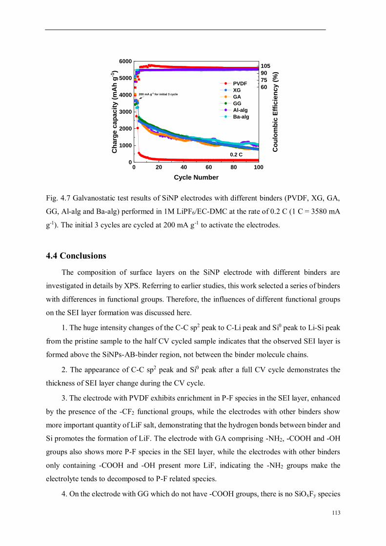
113
Fig. 4.7 Galvanostatic test results of SiNP electrodes with different binders (PVDF, XG, GA,
GG, Al-alg and Ba-alg) performed in 1M LiPF6/EC-DMC at the rate of 0.2 C (1 C = 3580 mA
g-1). The initial 3 cycles are cycled at 200 mA g-1 to activate the electrodes.
4.4 Conclusions
The composition of surface layers on the SiNP electrode with different binders are
investigated in details by XPS. Referring to earlier studies, this work selected a series of binders
with differences in functional groups. Therefore, the influences of different functional groups
on the SEI layer formation was discussed here.
1. The huge intensity changes of the C-C sp2 peak to C-Li peak and Si0 peak to Li-Si peak
from the pristine sample to the half CV cycled sample indicates that the observed SEI layer is
formed above the SiNPs-AB-binder region, not between the binder molecule chains.
2. The appearance of C-C sp2 peak and Si0 peak after a full CV cycle demonstrates the
thickness of SEI layer change during the CV cycle.
3. The electrode with PVDF exhibits enrichment in P-F species in the SEI layer, enhanced
by the presence of the -CF2 functional groups, while the electrodes with other binders show
more important quantity of LiF salt, demonstrating that the hydrogen bonds between binder and
Si promotes the formation of LiF. The electrode with GA comprising -NH2, -COOH and -OH
groups also shows more P-F species in the SEI layer, while the electrodes with other binders
only containing -COOH and -OH present more LiF, indicating the -NH2 groups make the
electrolyte tends to decomposed to P-F related species.
4. On the electrode with GG which do not have -COOH groups, there is no SiOxFy species
0 20 40 60 80 1000
1000
2000
3000
4000
5000
6000
0.2 C
Ch
arg
e c
ap
ac
ity
(m
Ah
g-1
)
Cycle Number
PVDF
XG
GA
GG
Al-alg
Ba-alg
200 mA g-1 for initial 3 cycle
60
75
90
105
Co
ulo
mb
ic E
ffic
ien
cy
(%
)

114
formed after half CV cycle but a little quantity can be observed after a full CV cycle. In
comparison, the electrodes with XG, GA, Al-alg and Ba-alg which have -COOH groups, exhibit
a SiOxFy peak at half CV cycle and do not show this peak after a full CV cycle. It demonstrates
that -COOH groups could influence the formation of SiOxFy species on the electrode.
5. The electrodes with Ba-alg shows only a very weak peak corresponding to SiOxFy
species after half CV cycle although it was fully lithiated (proved by CV and galvanostatic
profiles), while the electrode with Al-alg shows mainly a SiOxFy peak with a small amount of
Li-Si species. On the other hand, the electrode with Ba-alg shows no C-Li signal in C 1s profile,
while the electrode with Al-alg exhibits a small C-Li peak, demonstrating that the surface layer
on the electrode with Ba-alg is thicker than that with Al-alg. Therefore, it indicates that the
formation of SiOxFy species is on the surface of Si so that it can be detected on the electrode
with Ba-alg and the Li-Si alloying takes place more inside the SiNPs thus it is not visible when
the surface layer is thicker.
6. The XPS spectra of N 1s, Al 2p and Ba 3d profiles for the electrodes with GA, Al-alg
and Ba-alg, respectively, indicate that very low amounts of N, Al and Ba species are present in
the corresponding electrodes. These species are not significantly changing the chemical surface
composition of the SEI layer but can have influence on the decomposition of electrolyte.

115
References [1] J.-T. Li, Z.-Y. Wu, Y.-Q. Lu, Y. Zhou, Q.-S. Huang, L. Huang, S.-G. Sun, Water Soluble
Binder, an Electrochemical Performance Booster for Electrode Materials with High Energy Density, Adv. Energy Mater. 7 (2017) 1701185. https://doi.org/10.1002/aenm.201701185.
[2] T. Kwon, J.W. Choi, A. Coskun, The emerging era of supramolecular polymeric binders in silicon anodes, Chem. Soc. Rev. 47 (2018) 2145-2164. https://doi.org/10.1039/C7CS00858A.
[3] S. Huang, J. Ren, R. Liu, M. Yue, Y. Huang, G. Yuan, The progress of novel binder as a non-ignorable part to improve the performance of Si-based anodes for Li-ion batteries, Int. J. Energy Res. 42 (2018) 919-935. https://doi.org/10.1002/er.3826.
[4] S. Choi, T. Kwon, A. Coskun, J.W. Choi, Highly elastic binders integrating polyrotaxanes for silicon microparticle anodes in lithium ion batteries, Science. 357 (2017) 279-283. https://doi.org/10.1126/science.aal4373.
[5] F. Zou, A. Manthiram, A Review of the Design of Advanced Binders for High‐Performance Batteries, Adv. Energy Mater. 10 (2020) 2002508. https://doi.org/10.1002/aenm.202002508.
[6] D. Mazouzi, B. Lestriez, L. Roué, D. Guyomard, Silicon Composite Electrode with High Capacity and Long Cycle Life, Electrochem. Solid-State Lett. 12 (2009) A215. https://doi.org/10.1149/1.3212894.
[7] A. Magasinski, B. Zdyrko, I. Kovalenko, B. Hertzberg, R. Burtovyy, C.F. Huebner, T.F. Fuller, I. Luzinov, G. Yushin, Toward Efficient Binders for Li-Ion Battery Si-Based Anodes: Polyacrylic Acid, ACS Appl. Mater. Interfaces. 2 (2010) 3004-3010. https://doi.org/10.1021/am100871y.
[8] E. Peled, S. Menkin, Review—SEI: Past, Present and Future, J. Electrochem. Soc. 164 (2017) A1703-A1719. https://doi.org/10.1149/2.1441707jes.
[9] Y. Chu, Y. Shen, F. Guo, X. Zhao, Q. Dong, Q. Zhang, W. Li, H. Chen, Z. Luo, L. Chen, Advanced Characterizations of Solid Electrolyte Interphases in Lithium-Ion Batteries, Electrochem. Energy Rev. (2019). https://doi.org/10.1007/s41918-019-00058-y.
[10] T. Zhang, I. de Meatza, X. Qi, E. Paillard, Enabling steady graphite anode cycling with high voltage, additive-free, sulfolane-based electrolyte: Role of the binder, J. Power Sources. 356 (2017) 97-102. https://doi.org/10.1016/j.jpowsour.2017.04.073.
[11] J.-P. Yen, C.-M. Lee, T.-L. Wu, H.-C. Wu, C.-Y. Su, N.-L. Wu, J.-L. Hong, Enhanced High-Temperature Cycle-Life of Mesophase Graphite Anode with Styrene-Butadiene Rubber/Carboxymethyl Cellulose Binder, ECS Electrochem. Lett. 1 (2012) A80-A82. https://doi.org/10.1149/2.008206eel.
[12] E.M.C. Jones, Ö.Ö. Çapraz, S.R. White, N.R. Sottos, Reversible and Irreversible Deformation Mechanisms of Composite Graphite Electrodes in Lithium-Ion Batteries, J. Electrochem. Soc. 163 (2016) A1965-A1974. https://doi.org/10.1149/2.0751609jes.
[13] K. Ui, D. Fujii, Y. Niwata, T. Karouji, Y. Shibata, Y. Kadoma, K. Shimada, N. Kumagai, Analysis of solid electrolyte interface formation reaction and surface deposit of natural graphite negative electrode employing polyacrylic acid as a binder, J. Power Sources. 247 (2014) 981-990. https://doi.org/10.1016/j.jpowsour.2013.08.083.
[14] N. Dupré, P. Moreau, E. De Vito, L. Quazuguel, M. Boniface, A. Bordes, C. Rudisch, P. Bayle-Guillemaud, D. Guyomard, Multiprobe Study of the Solid Electrolyte Interphase on Silicon-Based Electrodes in Full-Cell Configuration, Chem. Mater. 28 (2016) 2557-2572. https://doi.org/10.1021/acs.chemmater.5b04461.
[15] F. Jeschull, F. Lindgren, M.J. Lacey, F. Björefors, K. Edström, D. Brandell, Influence of inactive electrode components on degradation phenomena in nano-Si electrodes for Li-ion batteries, J. Power Sources. 325 (2016) 513-524.

116
https://doi.org/10.1016/j.jpowsour.2016.06.059. [16] M. Ling, Y. Xu, H. Zhao, X. Gu, J. Qiu, S. Li, M. Wu, X. Song, C. Yan, G. Liu, S. Zhang,
Dual-functional gum arabic binder for silicon anodes in lithium ion batteries, Nano Energy. 12 (2015) 178-185. https://doi.org/10.1016/j.nanoen.2014.12.011.
[17] C.K. Chan, R. Ruffo, S.S. Hong, Y. Cui, Surface chemistry and morphology of the solid electrolyte interphase on silicon nanowire lithium-ion battery anodes, J. Power Sources. 189 (2009) 1132-1140. https://doi.org/10.1016/j.jpowsour.2009.01.007.
[18] C. Pereira-Nabais, J. Światowska, A. Chagnes, F. Ozanam, A. Gohier, P. Tran-Van, C.-S. Cojocaru, M. Cassir, P. Marcus, Interphase chemistry of Si electrodes used as anodes in Li-ion batteries, Appl. Surf. Sci. 266 (2013) 5-16. https://doi.org/10.1016/j.apsusc.2012.10.165.
[19] V. Etacheri, O. Haik, Y. Goffer, G.A. Roberts, I.C. Stefan, R. Fasching, D. Aurbach, Effect of Fluoroethylene Carbonate (FEC) on the Performance and Surface Chemistry of Si-Nanowire Li-Ion Battery Anodes, Langmuir. 28 (2012) 965-976. https://doi.org/10.1021/la203712s.
[20] C.C. Nguyen, S.-W. Song, Characterization of SEI layer formed on high performance Si-Cu anode in ionic liquid battery electrolyte, Electrochem. Commun. 12 (2010) 1593-1595. https://doi.org/10.1016/j.elecom.2010.09.003.
[21] B. Philippe, R. Dedryvère, J. Allouche, F. Lindgren, M. Gorgoi, H. Rensmo, D. Gonbeau, K. Edström, Nanosilicon Electrodes for Lithium-Ion Batteries: Interfacial Mechanisms Studied by Hard and Soft X-ray Photoelectron Spectroscopy, Chem. Mater. 24 (2012) 1107-1115. https://doi.org/10.1021/cm2034195.
[22] L.-F. Cui, R. Ruffo, C.K. Chan, H. Peng, Y. Cui, Crystalline-Amorphous Core−Shell Silicon Nanowires for High Capacity and High Current Battery Electrodes, Nano Lett. 9 (2009) 491-495. https://doi.org/10.1021/nl8036323.
[23] B. Laïk, D. Ung, A. Caillard, C. Sorin Cojocaru, D. Pribat, J.-P. Pereira-Ramos, An electrochemical and structural investigation of silicon nanowires as negative electrode for Li-ion batteries, J. Solid State Electrochem. 14 (2010) 1835-1839. https://doi.org/10.1007/s10008-010-1045-5.
[24] X. Hou, M. Zhang, J. Wang, S. Hu, X. Liu, Z. Shao, High yield and low-cost ball milling synthesis of nano-flake Si@SiO2 with small crystalline grains and abundant grain boundaries as a superior anode for Li-ion batteries, J. Alloys Compd. 639 (2015) 27-35. https://doi.org/10.1016/j.jallcom.2015.03.127.
[25] M. Green, E. Fielder, B. Scrosati, M. Wachtler, J.S. Moreno, Structured Silicon Anodes for Lithium Battery Applications, Electrochem. Solid-State Lett. 6 (2003) A75. https://doi.org/10.1149/1.1563094.
[26] E. Pollak, G. Salitra, V. Baranchugov, D. Aurbach, In Situ Conductivity, Impedance Spectroscopy, and Ex Situ Raman Spectra of Amorphous Silicon during the Insertion/Extraction of Lithium, J. Phys. Chem. C. 111 (2007) 11437-11444. https://doi.org/10.1021/jp0729563.
[27] M. Gauthier, J. Danet, B. Lestriez, L. Roué, D. Guyomard, P. Moreau, Nanoscale compositional changes during first delithiation of Si negative electrodes, J. Power Sources. 227 (2013) 237-242. https://doi.org/10.1016/j.jpowsour.2012.11.047.
[28] L.B. Chen, J.Y. Xie, H.C. Yu, T.H. Wang, An amorphous Si thin film anode with high capacity and long cycling life for lithium ion batteries, J. Appl. Electrochem. 39 (2009) 1157-1162. https://doi.org/10.1007/s10800-008-9774-1.
[29] V. Baranchugov, E. Markevich, E. Pollak, G. Salitra, D. Aurbach, Amorphous silicon thin films as a high capacity anodes for Li-ion batteries in ionic liquid electrolytes, Electrochem. Commun. 9 (2007) 796-800. https://doi.org/10.1016/j.elecom.2006.11.014.
[30] X. Huang, Z. Wang, R. Knibbe, B. Luo, S.A. Ahad, D. Sun, L. Wang, Cyclic Voltammetry in Lithium-Sulfur Batteries—Challenges and Opportunities, Energy Technol. (2019)

117
ente.201801001. https://doi.org/10.1002/ente.201801001. [31] L. Shan, C. Yurong, Y. Jing, R. Feixia, W. Jun, S. Babu, Y. Xin, G. Junkuo, Y. Juming,
Entrapment of polysulfides by a Ketjen Black & mesoporous TiO2 modified glass fiber separator for high performance lithium-sulfur batteries, J. Alloys Compd. 779 (2019) 412-419. https://doi.org/10.1016/j.jallcom.2018.11.261.
[32] Z.A. Ghazi, X. He, A.M. Khattak, N.A. Khan, B. Liang, A. Iqbal, J. Wang, H. Sin, L. Li, Z. Tang, MoS2/Celgard Separator as Efficient Polysulfide Barrier for Long-Life Lithium-Sulfur Batteries, Adv. Mater. 29 (2017) 1606817. https://doi.org/10.1002/adma.201606817.
[33] J. Liu, Q. Zhang, T. Zhang, J.-T. Li, L. Huang, S.-G. Sun, A Robust Ion-Conductive Biopolymer as a Binder for Si Anodes of Lithium-Ion Batteries, Adv. Funct. Mater. 25 (2015) 3599-3605. https://doi.org/10.1002/adfm.201500589.
[34] Z.-Y. Wu, L. Deng, J.-T. Li, Q.-S. Huang, Y.-Q. Lu, J. Liu, T. Zhang, L. Huang, S.-G. Sun, Multiple hydrogel alginate binders for Si anodes of lithium-ion battery, Electrochimica Acta. 245 (2017) 371-378. https://doi.org/10.1016/j.electacta.2017.05.094.
[35] Y.K. Jeong, T. Kwon, I. Lee, T.-S. Kim, A. Coskun, J.W. Choi, Millipede-inspired structural design principle for high performance polysaccharide binders in silicon anodes, Energy Environ. Sci. 8 (2015) 1224-1230. https://doi.org/10.1039/C5EE00239G.
[36] B. Philippe, R. Dedryvère, M. Gorgoi, H. Rensmo, D. Gonbeau, K. Edström, Role of the LiPF 6 Salt for the Long-Term Stability of Silicon Electrodes in Li-Ion Batteries - A Photoelectron Spectroscopy Study, Chem. Mater. 25 (2013) 394-404. https://doi.org/10.1021/cm303399v.
[37] P. Verma, P. Maire, P. Novák, A review of the features and analyses of the solid electrolyte interphase in Li-ion batteries, Electrochimica Acta. 55 (2010) 6332-6341. https://doi.org/10.1016/j.electacta.2010.05.072.
[38] B. Philippe, M. Hahlin, K. Edström, T. Gustafsson, H. Siegbahn, H. Rensmo, Photoelectron Spectroscopy for Lithium Battery Interface Studies, J. Electrochem. Soc. 163 (2015) A178-A191. https://doi.org/10.1149/2.0051602jes.
[39] A.M. Andersson, K. Edström, Chemical Composition and Morphology of the Elevated Temperature SEI on Graphite, J. Electrochem. Soc. 148 (2001) A1100. https://doi.org/10.1149/1.1397771.
[40] S. Malmgren, K. Ciosek, M. Hahlin, T. Gustafsson, M. Gorgoi, H. Rensmo, K. Edström, Comparing anode and cathode electrode/electrolyte interface composition and morphology using soft and hard X-ray photoelectron spectroscopy, Electrochimica Acta. 97 (2013) 23-32. https://doi.org/10.1016/j.electacta.2013.03.010.
[41] K. Konstadinidis, P. Zhang, R.L. Opila, D.L. Allara, An in-situ X-ray photoelectron study of the interaction between vapor-deposited Ti atoms and functional groups at the surfaces of self-assembled monolayers, Surf. Sci. 338 (1995) 300-312. https://doi.org/10.1016/0039-6028(95)80048-4.
[42] S.-H. Kang, D.P. Abraham, A. Xiao, B.L. Lucht, Investigating the solid electrolyte interphase using binder-free graphite electrodes, J. Power Sources. 175 (2008) 526-532. https://doi.org/10.1016/j.jpowsour.2007.08.112.
[43] F. Chang-Ling, X. Zhong-Yu, Lithium storage function of acetylene black in the negative electrodes of lithium ion batteries, Carbon Tech. (2007) 19-21.
[44] K. Xu, A. von Cresce, Interfacing electrolytes with electrodes in Li ion batteries, J. Mater. Chem. 21 (2011) 9849. https://doi.org/10.1039/c0jm04309e.
[45] A. Bordes, K. Eom, T.F. Fuller, The effect of fluoroethylene carbonate additive content on the formation of the solid electrolyte interphase and capacity fade of Li-ion full-cell employing nano Si-graphene composite anodes, J. Power Sources. 257 (2014) 163-169. https://doi.org/10.1016/j.jpowsour.2013.12.144.
[46] V. Etacheri, U. Geiger, Y. Gofer, G.A. Roberts, I.C. Stefan, R. Fasching, D. Aurbach,

118
Exceptional Electrochemical Performance of Si-Nanowires in 1,3-Dioxolane Solutions: A Surface Chemical Investigation, Langmuir. 28 (2012) 6175-6184. https://doi.org/10.1021/la300306v.
[47] I. Kovalenko, B. Zdyrko, A. Magasinski, B. Hertzberg, Z. Milicev, R. Burtovyy, I. Luzinov, G. Yushin, A Major Constituent of Brown Algae for Use in High-Capacity Li-Ion Batteries, Science. 334 (2011) 75-79. https://doi.org/10.1126/science.1209150.
[48] Ch. Cardinaud, A. Rhounna, G. Turban, B. Grolleau, Analyse XPS des surfaces de Si et SiO2 exposées aux plasmas de CHF3 et CHF3—C2F6. Polymérisation et gravure, Rev. Phys. Appliquée. 24 (1989) 309-321. https://doi.org/10.1051/rphysap:01989002403030900.
[49] D.T. Clark, W.J. Feast, D. Kilcast, W.K.R. Musgrave, Applications of ESCA to polymer chemistry. III. Structures and bonding in homopolymers of ethylene and the fluoroethylenes and determination of the compositions of fluoro copolymers, J. Polym. Sci. Polym. Chem. Ed. 11 (1973) 389-411. https://doi.org/10.1002/pol.1973.170110207.
[50] A. Ermolieff, F. Martin, A. Amouroux, S. Marthon, J.F.M. Westendorp, Surface composition analysis of HF vapour cleaned silicon by X-ray photoelectron spectroscopy, Appl. Surf. Sci. 48-49 (1991) 178-184. https://doi.org/10.1016/0169-4332(91)90327-G.
[51] K.J. Gruntz, L. Ley, R.L. Johnson, Photoelectron spectra of fluorinated amorphous silicon (a -Si: F), Phys. Rev. B. 24 (1981) 2069-2080. https://doi.org/10.1103/PhysRevB.24.2069.
[52] L.A. Zazzera, XPS and SIMS Study of Anhydrous HF and UV/Ozone-Modified Silicon (100) Surfaces, J. Electrochem. Soc. 136 (1989) 484. https://doi.org/10.1149/1.2096659.
[53] R. Dedryvère, L. Gireaud, S. Grugeon, S. Laruelle, J.-M. Tarascon, D. Gonbeau, Characterization of Lithium Alkyl Carbonates by X-ray Photoelectron Spectroscopy: Experimental and Theoretical Study, J. Phys. Chem. B. 109 (2005) 15868-15875. https://doi.org/10.1021/jp051626k.
[54] E. Radvanyi, E. De Vito, W. Porcher, S. Jouanneau Si Larbi, An XPS/AES comparative study of the surface behaviour of nano-silicon anodes for Li-ion batteries, J Anal Spectrom. 29 (2014) 1120-1131. https://doi.org/10.1039/C3JA50362C.
[55] P.J.W. Weijs, J.C. Fuggle, P.A.M. van der Heide, The Ba/Si(100)-2 × 1 interface, Surf. Sci. 260 (1992) 97-101. https://doi.org/10.1016/0039-6028(92)90022-X.
[56] J. Zachariae, H. Pfnür, Growth conditions, stoichiometry, and electronic structure of lattice-matched Sr O ∕ Ba O mixtures on Si(100), Phys. Rev. B. 72 (2005) 075410. https://doi.org/10.1103/PhysRevB.72.075410.
[57] A. Lehner, G. Steinhoff, M.S. Brandt, M. Eickhoff, M. Stutzmann, Hydrosilylation of crystalline silicon (111) and hydrogenated amorphous silicon surfaces: A comparative x-ray photoelectron spectroscopy study, J. Appl. Phys. 94 (2003) 2289-2294. https://doi.org/10.1063/1.1593223.
[58] J. Liu, Q. Zhang, Z.-Y. Wu, J.-H. Wu, J.-T. Li, L. Huang, S.-G. Sun, A high-performance alginate hydrogel binder for the Si/C anode of a Li-ion battery, Chem. Commun. 50 (2014) 6386. https://doi.org/10.1039/c4cc00081a.

119
Supplementary informations
Fig. 4-S1 SEM images of pristine SiNP electrodes with (a) GG, (b) XG, (c) GA, (d) Al-alg, (e)
Ba-alg and (f) PVDF binders.
The morphology of SiNP electrodes with different binders are shown in Fig. 4-S1. The
size of the SiNPs are around 50-100 nm. The particles much smaller than SiNPs should be the
AB conductive agent on the electrode. It could be observed that two or more SiNPs are usually
connected together by the using of binders. Therefore, the SiNPs exhibit different degrees of
aggregation on different electrodes. The electrode with PVDF shows the aggregation degree
much lower than the other electrodes, demonstrating the weak mechanical properties of PVDF.

120
Fig. 4-S2 A comparative analysis of relative intensity ratios of different species for C 1s, F 1s
O 1s and Si 2p core levels peaks obtained for Si electrodes with different binders (GG, XG, GA,
Al-alg, Ba-alg and PVDF) at different states (pristine, after half CV cycle (0.01 V) and after
full CV cycle (3.0 V)).

121
Chapter 5
Development of a binder free Si@C-network electrode and its
influence on SEI layer formation
5.1 Introduction
Numerous strategies have been proposed in the last decade to overcome the challenges in
the application of Si anode. The synthesis of Si composites, such as Si-C [1,2] and Si-alloy
composites [3,4] can improve the electric conductivity and reduce the interfacial reactions to
optimize the electrochemical performance. The exploitation of novel functional binders for Si
based electrodes has received widespread attention in recent years to keep the electrode
integrity and thus improve the electrochemical performance [5,6]. However, the ratio of active
Si on the electrode is usually decreased by these strategies. Therefore, the binder-free electrode
structure was proposed aiming at reducing the non-conductive and inactive components,
changing a typical contact mode between Si particle and conductive agent, and improving the
electrode conductivity and practical capacity.
Removing copper collector, the Si electrode with pure carbon substrate becomes a research
hot topic [7,8]. However, this kind of electrode can be easily destroyed due to the brittleness of
carbon substrate caused by the insertion/extraction of lithium ion during charge and discharge
process [9]. In recent two years, several binder-free Si electrodes fabricated on the current
collector have been reported [10-12]. However, according to our knowledge, the SEI layer
formation on these new binder-free Si-based electrode materials was not discussed.
In this chapter, a Si@C-network electrode using a high viscosity water-based polymer as
the conductive network precursor was designed and prepared in the collaboration of the group
in Xiamen University. Then, the in-depth surface characterization of this binder-free Si@C-
network electrode material with application of X-ray photoelectron spectroscopy (XPS) and
Time-of-Flight Secondary Ion Mass Spectrometry (ToF-SIMS) techniques was performed in
our laboratory at Chimie-ParisTech to investigate the surface modifications as a function of
lithiation and delithiations potentials. The material synthesis, Fourier transform infrared
spectrometry (FTIR), Raman spectroscopy, thermogravimetric analysis (TGA) and
transmission electron microscopy (TEM) presented in this chapter have been included in our
paper published recently [13]. The binder-free Si@C-network electrode was compared with the
binder-containing Si electrode (Si-XG-acetylene black (Si-XG-AB)). The surface

122
characterizations of these samples at different states of lithiation/delithiation are going to be the
object of the next paper (in preparation).
5.2 Experimental part
5.2.1 Electrode preparation
5.2.1.1 Preparation of Si@C-network electrode
The Si@C-network electrode was prepared by the in situ carbonization. The material
synthesis was performed in collaboration with Xiamen University and presented in the recent
paper [13]. 0.05 g xanthan gum (XG, Aladdin, Shanghai, China, USP) was dissolved in 1.5 mL
deionized water, then 0.05 g Si (Alfa Aesar, 50-100 nm) was mixed together to form a
homogeneous gel by magnetic stirring for 24 hours. The homogeneous gel was then coated on
a roughened copper current collector (by using a 300 mesh sandpaper) to make the gel well
adhered on the copper. After that, it was air-dried to evaporate the water, and dried overnight at
100 °C in vacuum to prepare the Si-XG precursor. The copper current collectors with or without
Si-XG were weighed respectively to calculate the weight of Si active material. Finally, the
Si@C-network electrode was obtained by the carbonization of Si-XG precursor at 600 °C under
Ar atmosphere for 2 hours with the heating rate of 5 °C min-1. The scheme of preparation
process of Si@C-network electrode is illustrated in Fig. 5.1. The XG polymer surrounding the
Si nanoparticles
Fig. 5.1 Schematic illustration of the preparation of Si@C-network electrode [13].
5.2.1.2 Preparation of binder containing Si-XG-AB electrode
For a comparison, the Si-XG-AB electrode was prepared by coating the homogeneous
slurry, which composed of Si nanoparticles (SiNPs, 60 wt%), AB (20 wt%), and XG (20 wt%),
on the copper current collector. After drying in air, the electrode was dried overnight in a
vacuum at 100 °C. The mass loading of the active Si is 0.4 mg cm-2 on both Si@C-network
electrode and Si-XG-AB electrode.

123
5.2.2 Characterizations of pristine electrodes
The Fourier transform infrared (FTIR, NICOLET IN10) spectrometry was performed
between the range of 3950 to 750 cm-1 on Si-XG precursor and Si@C-network electrode to
investigate the interaction changes before and after carbonization. The Raman spectroscopy
(XploRA, HORIBA) was performed between the range of 2500 to 200 cm-1to observe the
structure change information on the same samples before and after carbonization.
Thermogravimetric analysis were performed using TA Q600 with a heating rate of 10 °C min-1
from 25 °C to 800 °C to investigate the Si weight ratio on Si@C-network electrode. The
morphological characterizations of Si-XG-AB electrode and Si@C-network electrode were
performed by SEM (Zeiss Ultra55 microscope with high-resolution field emission gun,
Schottky SEM-FEG). The transmission electron microscopy (JEOL, JEM2100) operates at 200
kV were employed to analyze the microstructure of Si nanoparticles and Si@C-network
composite.
5.2.3 XPS and ToF-SIMS analyzations
5.2.3.1 Sample preparation for XPS and ToF-SIMS
Fig. 5.2 shows the first cycle charge-discharge curves for XPS and ToF-SIMS sample
preparations performed in 1M LiPF6/dimethyl carbonate (DMC) electrolyte at 200 mA g-1 in
Swagelok cells. As shown in Fig. 5.2 (a) and (b), during the first cycle charge-discharge, 4
points were chosen for each type of electrode to prepare the samples for XPS and ToF-SIMS
characterizations:
- point 1 (~0.8-1.0 V) corresponding to the state after electrolyte decomposition and
SEI formation [14-18],
- point 2 (~0.1-0.3 V) corresponding to the further formation of SEI layer before the
lithiation of crystalline Si [19-21],
- points 3 (0.01 V) corresponding to the full lithiated state of the electrode [22-24],
- point 4 (3.0 V) corresponding to the full delithiated state of the electrode.
At each point, the cycling was stopped and the sample was immediately transferred into
the Ar-filled glove box. Then, the cell was disassembled and rinsed with DMC, dried with Ar-
flow and transferred directly to the XPS or ToF-SIMS analysis chamber under anaerobic and
anhydrous conditions.

124
Fig. 5.2 The first cycle charge-discharge curves of (a) Si-XG-AB electrode and (b) Si@C-
network electrode for XPS and ToF-SIMS sample preparations performed in 1M LiPF6/DMC
electrolyte at 200 mA g-1.
5.2.3.2 XPS and ToF-SIMS experimental conditions
The XPS and ToF-SIMS conditions were almost the same as the conditions described in
Chapter 3 section 3.2.3 and 3.2.5. The only difference is that the sputtering area for ToF-SIMS
depth profiles in this chapter was only 300* 300 m2. The 500* 500 m2 sputtering area was
not used here.
5.2.4 Galvanostatic tests
The long-term galvanostatic test for Si-XG-AB and Si@C-network electrodes were
performed by a VMP3 Biologic multi-channel potentiostat/galvanostat at the rate of 0.2 C (1 C
= 3580 mAh g-1) in 1M LiPF6/DMC. The initial cycle was performed with the current of 200
mA g-1 to activate the electrodes.
5.3 Results and discussion
5.3.1 Fourier transform infrared spectrometry, Raman spectroscopy and
thermogravimetric analyzations
The FTIR spectrometry was used to detect the interactions between Si and XG, as
displayed in Fig. 5.3 (a). The silanol groups of silica layer on the surface of Si particle are the
crucial factor to form the interactions between Si and XG [25]. The formation of hydrogen
bonding between Si and XG is proved by the shift of the stretching of O-H and CH2-OH bonds,
which shift from 3378 cm-1 and 1049 cm-1 to 3389 cm-1 and 1073 cm-1 after XG mixed with
SiNPs. The antisymmetric and symmetric stretching of COO- shift from 1605 cm-1 and 1405

125
cm-1 to 1611 cm-1 and 1414 cm-1, suggesting the ion-dipole interaction exists between Si and
XG. This FTIR result is consistent with the reported works [26,27]. After carbonization, the
stretching bands of CH2-OH and the antisymmetric and symmetric stretching of COO- almost
disappear on Si@C-network composite. Besides, Si@C-network composite has a strong
absorption peak at 1243 cm-1, originated from the Si-O bond on the surface of Si.
Fig. 5.3 (a) The FTIR spectra of Si, XG, Si-XG precursor and Si@C-network composite. (b)
Raman spectra of Si, Si-XG precursor and Si@C-network composite. (c) TG curves of Si and
Si@C-network composite tested in air atmosphere.
As shown in Fig. 5.3 (b), the formation of carbon-network in Si@C-network composite
can be demonstrated by Raman spectroscopy. For Si-XG composite, one prominent peak is
observed at 503 cm-1, corresponding to the lattice vibration of polysilicon. Besides, two peaks
at 927 cm-1 and 283 cm-1 are classified to the stretching vibration and the bending vibration of
Si-O-Si from silica, indicating that the nanosized-Si particle is covered by a silica thin layer
[28-31]. After carbonization, two emerged peaks at 1335 cm-1 and 1600 cm-1 belong to the D
and G bands of carbon, respectively [28]. What is noteworthy is that the peak of polysilicon
lattice vibration of SiNPs is 517 cm-1, which is different from that of Si-XG and Si@C-network
composites. This difference is attributed to the transverse optical mode by the previous reports,
indicating a thin carbon layer on the SiNPs and a facial contact mode between SiNPs and
conductive carbon [32-34].
In order to analyze the content of carbon in Si@C-network composite, the Si and Si@C-
network composite were tested by TG in air atmosphere, as displayed in Fig. 5.3 (c). The mass

126
of Si increases with the temperature rise corresponding to the formation of silica, while the
mass of C decreasing because of the formation of CO2. Therefore, the difference mass loss
between Si and Si@C-network composite at 600 °C is about 16.6%, indicating the Si content
is 83.4 wt.% in Si@C-network composite.
5.3.2 Morphology characterizations and electrochemical tests
5.3.2.1 Morphological characterization of electrodes by SEM and TEM
The SEM images of Si-XG-AB and Si@C-network electrodes before and after cycling are
shown in Fig. 5.4. Before cycling, the Si@C-network electrode presents the SiNPs sized 50-
100 nm covered by carbon-network (Fig. 5.4 (b)), while the Si-XG-AB exhibits the SiNPs sized
50-100 nm together with the AB particles sized 5-10 nm covered by XG binder (Fig. 5.4. (a)).
The zoomed figures of pristine Si-XG-AB and Si@C-network electrodes are shown in Fig. 5-
S1 to present the SiNPs and AB particles more clearly. Si nanoparticles and Si@C-network
composite was also analyzed by TEM and the results are shown in Fig. 5-S2. The Si
nanoparticles with the diameter of about 50 nm (Fig. 5-S2 (a)) are covered by the silica layer
with average thickness of 1.7 nm (Fig. 5-S2 (b)). In the HR-TEM image of Si nanoparticle (Fig.
5-S2 (b)), the lattice spacing of the Si crystal ((111) plane) is 0.31 nm [31]. In Fig. 5-S2 (c) and
(d) the facial connection of Si nanoparticle with the amorphous carbon can be clearly observed,
which constitutes the carbon conductive network. The active component, Si nanoparticles, is
coated homogenously by the amorphous carbon and interconnects with each other through the
carbon conductive network.
After 100 cycles of galvanostatic tests, the Si@C-network electrode (Fig. 5.4 (d)) shows a
grainy morphology with bigger particle sizes than pristine sample. The Si-XG-AB electrode
(Fig. 5.4 (c)) also exhibits the bigger particles. However, it seems that more deposits were
formed on the particles, probably due to more significant decomposition of the electrolyte,
leading to a more flattened morphology. These flattened surfaces present more cracks, and
formation of SEI layer inside the cracks and thus consuming the electrolyte at each cycle, as
shown in Fig. 5.4 (e) and (f). The particle size increase observed for both types of electrodes
can be explained by the SEI layer deposited on the particle surface. Due to much less significant
formation of cracks in the case of Si@C (Fig. 5.4 (f)), it can be supposed that the electrode is
more stable during the 100 cycles and there is lower consumption of electrolyte can occur.

127
Fig. 5.4 Morphology of pristine (a) Si-XG-AB electrode, (b) Si@C-network electrode and after
galvanostatic cycling in LiPF6/DMC at 0.2 C for 100 cycles (c) (e) Si-XG-AB and (d) (f) Si@C-
network electrode.
5.3.2.2 Galvanostatic tests
Fig. 5.6 shows the long-term galvanostatic test results of Si-XG-AB and Si@C-network
electrodes at the rate of 0.2 C in 1M LiPF6/DMC. The initial cycle was performed with the
current of 200 mA g-1 to activate the electrodes. The Si-XG-AB and Si@C-network electrodes
exhibit their initial charge capacity of 2568.1 mAh g-1 and 2866.4 mAh g-1, respectively. After
100 cycles at 0.2 C, the Si-XG-AB electrode shows a very low capacity of 54.3 mAh g-1,
whereas the Si@C-network electrode still presents a capacity of 952.2 mAh g-1. The coulombic
128
efficiency of the Si-XG-AB electrode is very unstable during the 100 cycles, while the
coulombic efficiency of the Si@C-network electrode is relatively stable and slowly increasing
during the 100 cycles. The unstable coulombic efficiency of the Si-XG-AB electrode can be
explained by the continuous SEI layer formation every cycle due to the formation of cracks (as
demonstrated by SEM in Fig. 5.5) caused by the large volume changes of Si during the charge-
discharge processes. On the other hand, the continuous formation of SEI layer makes the
conductive agent loss the contact with Si and thus break the conductive network. The Si@C-
network electrode is more stable because the carbon layer around Si provides a good conductive
network which is more difficult to break. Thanks to this, the electrode shows less cracks (as
demonstrated by SEM in Fig. 5.5), and as a consequence less electrolyte is consumed during
the cycling.
Fig. 5.6 The galvanostatic test results of Si-XG-AB and Si@C-network electrode at the rate of
0.2 C (1C = 3580 mA g-1) in 1M LiPF6/DMC electrolyte with the initial cycle at 200 mA g-1 to
activate the electrodes.
5.3.3 XPS surface characterizations
XPS surface characterizations of Si-XG-AB electrode
In order to better understand the influence of binder-free Si-based electrode on the surface
modifications at different stages of lithiation and delithiation, the XPS was performed. First of
all, the XPS results are presented for binder-containg Si electrode, which is Si-XG-AB electrode.
Fig. 5.7 shows the high resolution XPS spectra of C 1s, F 1s, O 1s and Si 2p and the peak
0 20 40 60 80 1000
1000
2000
3000
4000
Si-XG-AB
Si@C-network
Ch
arg
e C
ap
ac
ity
/ m
Ah
g-1
Cycle Number
I = 0.2 C
0
20
40
60
80
100
Co
ulo
mb
ic E
ffic
ien
cy
/ %

129
decompositions for pristine and after different electrochemical states (point 1-4) during the first
charge-discharge cycle of Si-XG-AB electrodes (shown in Fig. 5.2). The binding energies of
all spectra were corrected with reference to C-H, C-C sp3 peak at 285.0 eV.
The pristine Si-XG-AB electrode exhibit a narrow peak at ~284.0 eV corresponding to C-
C sp2 bond [18], which is related to the 20 wt% of AB present in the electrode. The high
intensities of C-H, C-C sp3 peak and C-OH, -OCH3 peak (~287.1 eV) [15,35-38] can be
attributed to the organic species in XG binder molecule. After the electrolyte decomposition
and SEI formation (point 1), the intensity ratio of C-C sp2 peak decreases a little, illustrating
the formation of a thin SEI layer on the electrode. However, the intensities of the other species
do not show significant changes with the formation of SEI layer because the signals form XG
is stronger and overlapped with SEI signals. At more negative potential, after the further stages
of the SEI formation and the lithiation of Si oxide (point 2), the intensity ratio of C-C sp2 peak
decreases and the full width at half maximum (FWHM) of this peak increase from 1.15 eV to
1.5 eV. The attenuation of C-C sp2 peak confirms the thickening of SEI layer. The intensities of
the peaks at 286.5 eV, 288.9 eV and 290.0 eV increase, indicating the formation of C-O ether
linkage, O-C=O and carbonate species on the electrode surface, respectively. After the full
lithiation of Si electrode (point 3), there is a new peak formed at 282.5 eV corresponding to the
lithiation of AB [39]. The intensity of this peak is much lower than the C-C sp2 peak on the
sample before the lithiation of carbon, demonstrating a thick SEI layer formed on the surface,
which shield the signals from the SiNPs-AB-binder region. A small C-C sp2 peak can be still
observed at point 3, demonstrating that the AB is partly lithiated during the cycling. This
phenomenon was not observed on the Si-XG-AB electrode cycled in 1 M LiPF6/EC-DMC in
Chapter 4, demonstrating the SEI layer formed with 1 M LiPF6/DMC is thinner, which agrees
with the experimental results about the influence of the electrolytes in Chapter 3. The amount
of C-O ether linkage and carbonate species have further increased at this point, corresponding
to reactions (2)-(4) and (6) shown in Scheme 5.1. At point 4 of delithiation, the C-Li peak
disappears due to the C-Li delithiation. The peaks corresponding to C-O ether linkage and
carbonate species decrease a lot, indicating the decomposition of these species during the
delithiation. The shape of the XPS profiles at points 2 and 4 looks similar but quite different
from the profile of point 3, indicating that the SEI layer formed at the fully lithiated state is not
stable and easily decomposed.

130
Fig. 5.7 High resolution C 1s, F 1s, O 1s and Si 2p core level spectra obtained on the pristine
surface of the Si-XG-AB electrode and on the Si-XG-AB electrode after different stages of
lithiation/delithiation (points 1-4) in 1 M LiPF6/DMC.
There is no F 1s signal on the pristine Si-XG-AB electrode. At point 1, the intensity of F
1s signal is very weak. At point 2, a high intensity of Li-F species at 685.0 eV
[14,15,35,36,38,39] with a small amount of SiOF at 686.8 eV [40-43] corresponding to the
signals from Si surface can be observed. After full lithiation (point 3), the intensity of Li-F peak
becomes much higher, while the peaks corresponding to SiOF and P-F (688.0 eV) are nearly
invisible (total intensity ratio 5.40 % in F 1s spectra) [15,35,36,38,39], illustrating the thick SEI
layer formed on the electrode surface. After the full cycle at the delithiation state (point 4), the
SiOF signal from the Si surface becomes obvious, indicating the SEI layer becomes thinner.

131
Scheme 5.1 Reduction reactions on Si electrode in 1 M LiPF6/DMC electrolyte.
The O-C=O (533.6 eV), Si-O, C-O (532.9 eV) and C=O, P=O (532.0 eV) peaks
[15,35,36,39,40,44-47] are present in the O 1s spectra of Si-XG-AB pristine sample (Fig. 5.7).
The presence of the organic species can be attributed to the XG binder molecules. At point 1,
the C=O, P=O and C-O peak intensities increase significantly [36,39,40,45-47], due to the
formation of related organic species in the SEI layer. At point 2, the peak corresponding to
ROLi, LixSiOy (531.9 eV) appear, confirming the lithiation of Si oxide (reactions (13) and (14))
[18,45,48,49]. At point 3, at a fully lithiated state, the intensity of ROLi, LixSiOy peak further
increases and a Li-O peak appears at 530.5 eV according to the reaction (12) [50]. The decrease
of C-O, Si-O peak at this point can be attributed to the thickening of SEI layer, since the Si-O
signal is related to the bulk Si, and Si-O undergoes lithiation. After delithiation (point 4), the
LixSiOy decrease confirms a partial delithiation. The Li-O peak disappears and C=O, P=O
become the main species on the electrode.
The Si 2p spectrum displays Si 2p3/2 and Si 2p1/2 spin orbit doublet. The decomposition of
Si 2p core level peak shows that the surface of the pristine Si-XG-AB electrode is covered by
a thin layer composed of different Si oxides, which confirms the presence of Si-O signal in the
region of O 1s core level peak as aforementioned. The lowest binding energy peak at ~99.1 eV

132
(Si 2p3/2) can be attributed to Si0 [18,51] and the higher binding energy Si 2p3/2 peaks can be
attributed to different Si oxides (Si+ at ~100.1 eV, Si2+ at ~101.8 eV and Si4+ at ~103.5 eV)
[40,41,51-53]. At point 1, the Si 2p3/2 peaks corresponding to Si+ and Si2+ increase and the Si4+
peak decrease. It can be not only attributed to the reduction of Si oxide during discharge, but
also it can be assigned to the formation of Si fluorides, because the Si 2p peaks of Si oxides and
fluorides with the same Si valence are usually overlapped [40,41,51-53]. At point 2, the
intensities of the Si 2p peaks do not show significant changes, but the peaks are shifted to lower
binding energies because of the differential charging effect on different compounds formed on
the surface of Si electrode [15,52]. Therefore, after this point, the Si 2p peaks were assigned to
different Si compounds by calculating the difference in the binding energies corresponding to
Si0 and other Si peaks. After full lithiation (point 3), the intensity of Si 2p profiles becomes
much lower, indicating the SEI layer formed with 1 M LiPF6/DMC in thinner than those formed
with 1 M LiPF6/EC-DMC (shown in Chapter 4). The Si 2p3/2 peak at lowest binding energy
(96.2 eV) can be attributed to the Li-Si alloy [18]. The Si 2p3/2 peak 2.2 eV higher than Li-Si
can be attributed to Si+ and at that 3.9 eV higher than Li-Si can be attributed to Si2+ species
[40,41,51-53]. After delithiation (point 4), the Si 2p peaks are shifted back to higher binding
energy but still lower than those observed for the pristine sample. The peaks corresponding to
Si0, different oxides and fluorides and a new peak corresponding to SiOxFy (104.5 eV) [40,51,52]
can be distinguished.
XPS surface characterizations of Si@C-network electrode
This section presents the XPS results on the binder free Si@C-network electrode. Fig. 5.8
shows the high resolution XPS spectra of C 1s, F 1s, O 1s and Si 2p and the peak decompositions
for pristine and at different electrochemical states (point 1-4) during the first charge-discharge
cycle of Si@C-network electrode. Like for Si-XG-AB electrode binding energies of all spectra
were also corrected with reference to the C-H, C-C sp3 peak at 285.0 eV.
The C 1s profile at point 1 is nearly the same as the C 1s profile of the pristine sample.
Both of them present a very high peak corresponding to the carbon-network on the surface (C-
C sp2, 284.0 eV), a smaller peak corresponding to C-H, C-C sp3 contamination, while the other
peaks are nearly invisible, demonstrating that almost all the ingredients of XG are carbonized.
Although, the C 1s profiles have similar shapes for pristine sample and after the first lithiation
(point 1), the SEI formation can be evidenced comparing the F 1s and O 1s profiles showing
several differences. The pristine sample shows no F 1s signal while at point 1 a high intensity
of Li-F (685.0 eV) peak and lower intensities of SiOF (686.8 eV) and P-F peaks (688.0 eV) can

133
be observed. The pristine sample shows a high peak in O 1s corresponding to Si oxide (532.9
eV), while at point 1, the major species are C=O, P=O formed due to the decomposition of
electrolyte [18,36,39]. A decrease of the Si0 signal intensity in Si 2p core level region for the
sample at point 1 with reference to the pristine sample also confirms the formation of SEI layer.
Combining the results on C 1s, F 1s, O 1s and Si 2p together, it can be concluded that the SEI
formed on the surface of Si@C-network electrode at point 1 mainly occurs in the zones between
SiNPs and carbon inside the carbon-network as shown in Fig. 5.9.
At point 2 of lithiation, the C-C sp2 peak disappears and the C-H, C-C sp3 becomes the
major species, indicating the further growth of SEI layer, which covers the carbon-network of
the electrode. The decrease of SiOF peak in F 1s demonstrates the thicker SEI layer. The high
intensity peak at 531.9 eV can be mainly attributed to ROLi species and not to LixSiOy, because
even the carbon-network surrounding the SiNPs are covered by SEI layer, less Si-related signal
can be detected by XPS. The schematic diagram of the SEI growth at point 2 is also shown in
Fig. 5.9. Similar to the Si 2p profiles of the Si-XG-AB electrode (described above), the peaks
are shifted to lower binding energy because of the differences of charging effect of different
species. The intensity of Si 2p profile decrease significantly at point 2.
At point 3, the Si@C-network electrode is fully lithiated and the SEI layer is further
growing. The species distinguished in C 1s core level region are C-OH, -OCH3 and carbonate,
which are the main components originating from the decomposition of DMC solvent, as
reported in Chapter 3. The high intensities of ROLi, LixSiOy and C=O, P=O peaks in O 1s
spectra confirm the formation of CH3OLi and carbonate. There is a Li-O peak which is
commonly observed on Si-based electrode at fully lithiated state in previous chapters. The main
species in the area of F 1s spectra is Li-F, while the P-F and SiOF species are nearly invisible.
The Si 2p signal is significantly attenuated due to formation of the SEI layer thus difficult to be
decomposed. It can be deduced that there are Li-Si, Si2+, Si4+ and SiOxFy species with the
calculation of the differences between peak positions.
After the delithiation at point 4, the C 1s profile shows some slight modifications,
indicating that the composition of C-related species is negligible. The carbon-network is still
covered by the SEI layer. There is no C-O ether linkage species formed after the cycle in 1 M
LiPF6/DMC, which is in agreement with the results in Chapter 3. The SiOF peak in F 1s spectra
increases a little, illustrating the thickness of SEI layer decrease (as shown in Fig. 5.9). The Li-
O peak disappears after delithation and C=O, P=O becomes the major species in O 1s spectra.
In Si 2p spectra, the Li-Si peak disappears and the Si0 peak reappears with a high Si4+ signal.

134
Fig. 5.8 High resolution C 1s, F 1s, O 1s and Si 2p core level spectra obtained on the pristine
and after different stages of lithiation/delithiation (points 1-4) in 1 M LiPF6/DMC of Si@C-
network electrode.
Summarizing the XPS results, it could be concluded that many SEI layer species are easily
formed during the lithiation and then easily undergoes a decomposition during the delithiation
on the Si-XG-AB electrode. Therefore, the Si-XG-AB electrode consumes a high quantity of
electrolyte to form SEI layer at every cycle, which may decrease the coulombic efficiency.
What’s more, the continuous formation of SEI layer every cycle will isolate the SiNPs and the
AB particles and therefore break the conductive network on the electrode and result in the
capacity fading.
The SEI layer on Si@C-network electrode formed on the Si surface inside the carbon layer
in the beginning of lithiation (point 1), and then grew thicker to cover the carbon-network when

135
the electrode is further lithiated (points 2 and 3). During delithiation (point 4), the SEI layer
thickness slightly decreases but still covers the carbon-network, and the components SEI layer
do not change a lot during this process. Therefore, the Si@C-network electrode exhibits a more
stable SEI layer which is beneficial to the coulombic efficiency and cycle life of the electrode.
Fig. 5.9 Schematic diagram of the pristine Si@C-network electrode and after different stages
of lithiation/delithiation (points 1-4) on the Si@C-network electrode.
5.3.4 ToF-SIMS surface and bulk characterizations
To have a better insight into the surface variation of Si-XG-AB and Si@C-network
electrodes, a ToF-SIMS ion depth profile analysis was performed at all states of
lithiation/delithiation as for the XPS tests presented above. Fig. 5.10 shows the ToF-SIMS
negative ion depth profiles for Si-XG-AB and Si@C-network pristine electrodes with a
sputtering area of 300 m * 300 m. As observed by SEM in Fig. 5.5, the diameter of the SiNPs
on Si-XG-AB and Si@C-network electrodes are 50-100 nm. Thus, in the 100*100 m2
analyzed area, the high quantity of SiNPs can be sputtered and characterized. However, the
SiNPs are not homogenously and evenly distributed on the surface (as demonstrated on SEM
images in Fig. 5.5). Thus, the all particles will be not etched at the same time. In the beginning
of sputtering, the signals corresponding to binder layer on Si-XG-AB electrode and carbon-
network on Si@C-network electrode of the particles present on the top surface at higher
position will be detected. With the sputtering time increase, the particles present on the top
surface will be partially etched while the particles present deeper at lower position might be
still intact. As a result, a mixture of signals corresponding to the surface and inside of different
particles can be detected. For long sputtering time (of around 1000 s, not shown here), a stable
intensity of all ions can be observed already after around 150 s of sputtering. This stable signal
intensity can be explained by an in-depth uniform electrode composition made of homogenous
slurries. Therefore, our discussion here is focused on the signals of the first 200 s of sputtering
time corresponding to the layer covering the Si surface.

136
In this chapter, all the ToF-SIMS depth profiles are normalized by Cu- signal intensity
considering the Cu substrate is inactive during the cycle. The Cu signal observed in all profiles
can indicate that the electrode materials (Si-XG-AB and Si@C-network) do not form a
complete and compact layer on the Cu current collector.
In Fig. 5.10 (a), in the initial 24 s of the depth profile for pristine Si-XG-AB electrode,
shows increasing intensities of C3- signal from AB. SiC- signal from SiNPs shows also a slight
increase. The higher intensities of CH2- and CH3O- signals (corresponding to organic species)
in the beginning of sputtering show the enrichment in binder. Cu- signal from Cu substrate,
increase rapidly to reach a plateau at around 24 s of sputtering.
On the Si@C-network electrode, clearly a C3- peak before the Si3-, SiC and Cu- signals can
be observed, indicating the existence of carbon-network on the Si surface like demonstrated on
TEM images presented in Fig. 5-S2 (d).
Fig. 5.10 ToF-SIMS negative ion depth profiles for pristine (a) Si-XG-AB electrode; (b) Si@C-
network electrode (sputtering area 300 m * 300 m).
The ToF-SIMS depth profiles for Si-XG-AB electrode and Si@C-network electrodes at
point 1 and point 2 are shown in Fig. 5.11. At point 1 (Fig. 5.11 (a)), the Si-XG-AB electrode
shows a maximum intensity at around 25 s and a small decrease of the Li- and LiSi- species for
74 s, while the intensities of LiF2- increase in first 20 s and then become stable, demonstrating
there is a Li-rich area in the beginning.
For the Si@C-network electrode at point 1 (Fig. 5.11 (b)), the LiF2- signal shows the
maximum in the beginning and then decrease rapidly until 40 s. The C3- profile reach the
maximum at 10 s and then decrease. The CH2- profile reaches the maximum at 25 s and then

137
Fig. 5.11 ToF-SIMS negative ion depth profiles for Si-XG-AB electrode at (a) point 1 (c) point
2; Si@C-network electrode at (b) point 1 (d) point 2 (sputtering area 300 m *300 m).
decrease. The Cu- and Si3- signals becomes stable at 40 s. It demonstrates that LiF species in
the SEI layer deposited on surface of the carbon-network and the CH2- related organic species
mainly formed between carbon-network and Si particles. This is in agreement with the XPS
results at point 1. There are two interpretations for the enrichment of LiF and organic species
in different areas. One is that LiF salt is easier to deposit on the porous carbon-network than
organic species. The other is that the formation of LiF consumes the HF in the electrolyte
(reaction (8)-(11)), but the SEI layer form on carbon-network hinders the diffusion of HF from
the electrolyte into the area between carbon-network and Si. Therefore, it is more difficult for
LiF formation in the area between carbon-network and Si than the surface. At the same time,

138
more Li carbonate salt (organic species) retained without the reactions with HF in the area
between carbon-network and Si.
At point 2 (Fig. 5.11 (c)), the Si-XG-AB electrode presents the peaks of Li-, LiF2-, CH2
-,
LiO- and CH3O- before the C3-, Cu- and Si3- signals become stable, indicating that the SEI layer
is enriched in Li salt and organic compounds formed on the electrode surface. Comparing with
point 1 (Fig. 5.11 (a)), the intensities of Li-, LiO-, CH2-, CH3O- and LiSi- species have
significantly increased, indicating the further formation of SEI layer and the partial lithiation of
Si.
Similar with point 1 (Fig. 5.11 (b)), the LiF2- profile shows the maximum intensity in the
beginning and then a rapid decrease until 46 s on the Si@C-network electrode, indicating LiF
deposited on the surface of carbon at point 2 (Fig. 5.11 (d)). It exhibits the peaks of C3-, Li-,
CH2-, CH3O- and LiO- before showing the stable signals of Cu- and Si3-, demonstrating that the
organic species are well mixed with the carbon-network, different from the profiles obtained at
point 1 which shows organic species-rich area between carbon-network and Si. The intensities
of Li-, LiO-, CH2-, CH3O- and LiSi- signals show increase with reference to the profiles obtained
at point 1, demonstrating the growth of SEI layer and the partial lithiation of Si, similar to the
Si-XG-AB electrode.
The ToF-SIMS depth profiles for Si-XG-AB electrode and Si@C-network electrodes at
point 3 and point 4 are shown in Fig. 5.12. At point 3, the Si-XG-AB electrode is fully lithiated,
thus the Li-, LiF2- and LiSi- intensities become very high (Fig. 5.12 (a)). It shows LiF2
- and CH2-
peaks before obtaining the stable signals of Si3- and C3- corresponding to Si electrode material
and AB conductive agent, which is in agreement with the high intensities of LiF and organic
species observed by XPS at point 3. On Si@C-network electrode, it does not show a high signal
of C3- species (Fig. 5.12 (b)) as those at point 1 and 2 (Fig. 5.11 (b)(d)). This can be explained
by the plenty of organic species well mixed with the carbon-network because the organic
species can be also responsible for C3- signal which can decrease the intensity ratio of C3
- signal
originating from the carbon-network. Therefore, when the SEI layer is mixed with carbon layer,
it becomes enriched in organic species leading to the disappearing of C3- peak. It also shows
high intensities of LiF2- and CH2
- peaks before reaching stable Si3- and Cu- signals, confirming
the SEI layer is rich in LiF and organic species.
After delithiation at point 4 (Fig. 5.12 (c)), the LiSi- intensity decrease and Li- profile
changes from a stable signal at point 3 (Fig. 5.12 (a)) to a peak in the beginning, demonstrating
the dealloying of Li-Si. It still exhibits high CH2- and LiF2
- peaks in the beginning of sputtering,
illustrating that SEI layer is still present after delithiation. However, these two species show

139
Fig. 5.12 ToF-SIMS negative ion depth profiles for Si-XG-AB electrode at (a) point 3 (c) point
4; Si@C-network electrode at (b) point 3 (d) point 4 (sputtering area 300 m *300 m).
faster decrease than the Si-XG-AB electrode at point 3, indicating the SEI becomes thinner after
delithiation. After the delithiation of Si@C-network electrode (point 4, Fig. 5.12 (d)), the C3-,
Li-, CH2- and LiO- species present their peaks at the same position, similar to the Si@C-network
electrode at point 2 (Fig. 5.11 (d)), indicating the Li carbonate salts is still well mixed with the
carbon-network after delithiation. The LiF2- peak becomes wider than that at point 2, indicating
the LiF salt is also formed in the inner part of SEI layer after a full cycle. Comparing with point
3, most of the species at point 4 show the intensities decrease except for Si3-, demonstrating the
dealloying of Li-Si and the decomposition of Li-related and organic species in the SEI layer,
which is in agreement with XPS results in Fig. 5.8. The sputtering time for the Li and organic

140
species rich area at point 4 is 76 s, less than that at point 3 (102 s), indicating the SEI layer is
getting thinner during delithiation.
5.4 Conclusions
A binder-free Si@C-network electrode was designed and fabricated by in situ
carbonization. The Si@C-network electrode exhibits the active Si ratio of 83.4% with a loading
mass of 0.4 mg cm-1. The Si@C-network electrode shows a capacity retention of 33.2%, while
the Si-XG-AB electrode shows only exhibits a capacity retention of 2.1%, when cycled in 1M
LiPF6/DMC at 0.2 C for 100 cycles. The XPS results demonstrate that the SEI layer formed on
Si-XG-AB electrode will decompose from the fully lithiated state (main species carbonate and
C-O ether linkage) to the fully delithiated state (main species -OCH3 and O-C=O), while on the
Si@C-network electrode, the SEI layer only shows slight change during the delithiation (main
species -OCH3 and carbonate). The ToF-SIMS results illustrate that on the Si@C-network
electrode, a SEI layer rich in LiF on carbon-network surface and rich in organic species on Si
surface was formed in the beginning of lithiation. Then, the SEI layer covered the carbon-
network during further lithiation and grew thicker when the electrode was fully lithiated. After
full delithiation, the SEI layer became thinner but still covering the carbon-network. The
significant changes of the Si-XG-AB electrode from the fully lithiated state to the fully
delithiated state were also proved by ToF-SIMS. The ToF-SIMS and XPS results are in a good
agreement.

141
References
[1] H.J. Kwon, J.-Y. Hwang, H.-J. Shin, M.-G. Jeong, K.Y. Chung, Y.-K. Sun, H.-G. Jung,
Nano/Microstructured Silicon-Carbon Hybrid Composite Particles Fabricated with Corn Starch Biowaste as Anode Materials for Li-Ion Batteries, Nano Lett. 20 (2020) 625-635. https://doi.org/10.1021/acs.nanolett.9b04395.
[2] J.-Y. Li, G. Li, J. Zhang, Y.-X. Yin, F.-S. Yue, Q. Xu, Y.-G. Guo, Rational Design of Robust Si/C Microspheres for High-Tap-Density Anode Materials, ACS Appl. Mater. Interfaces. 11 (2019) 4057-4064. https://doi.org/10.1021/acsami.8b20213.
[3] L. Deng, Z.-Y. Wu, Z.-W. Yin, Y.-Q. Lu, Z.-G. Huang, J.-H. You, J.-T. Li, L. Huang, S.-G. Sun, High-performance Si Mn/C composite anodes with integrating inactive Mn4Si7 alloy for lithium-ion batteries, Electrochimica Acta. 260 (2018) 830-837. https://doi.org/10.1016/j.electacta.2017.12.048.
[4] S. Chae, M. Ko, S. Park, N. Kim, J. Ma, J. Cho, Micron-sized Fe-Cu-Si ternary composite anodes for high energy Li-ion batteries, Energy Environ. Sci. 9 (2016) 1251-1257. https://doi.org/10.1039/C6EE00023A.
[5] T. Kwon, J.W. Choi, A. Coskun, The emerging era of supramolecular polymeric binders in silicon anodes, Chem. Soc. Rev. 47 (2018) 2145-2164. https://doi.org/10.1039/C7CS00858A.
[6] J.-T. Li, Z.-Y. Wu, Y.-Q. Lu, Y. Zhou, Q.-S. Huang, L. Huang, S.-G. Sun, Water Soluble Binder, an Electrochemical Performance Booster for Electrode Materials with High Energy Density, Adv. Energy Mater. 7 (2017) 1701185. https://doi.org/10.1002/aenm.201701185.
[7] A.K. Roy, M. Zhong, M.G. Schwab, A. Binder, S.S. Venkataraman, Ž. Tomović, Preparation of a Binder-Free Three-Dimensional Carbon Foam/Silicon Composite as Potential Material for Lithium Ion Battery Anodes, ACS Appl. Mater. Interfaces. 8 (2016) 7343-7348. https://doi.org/10.1021/acsami.5b12026.
[8] Z.-L. Xu, B. Zhang, J.-K. Kim, Electrospun carbon nanofiber anodes containing monodispersed Si nanoparticles and graphene oxide with exceptional high rate capacities, Nano Energy. 6 (2014) 27-35. https://doi.org/10.1016/j.nanoen.2014.03.003.
[9] Y. Liu, H. Zheng, X.H. Liu, S. Huang, T. Zhu, J. Wang, A. Kushima, N.S. Hudak, X. Huang, S. Zhang, S.X. Mao, X. Qian, J. Li, J.Y. Huang, Lithiation-Induced Embrittlement of Multiwalled Carbon Nanotubes, ACS Nano. 5 (2011) 7245-7253. https://doi.org/10.1021/nn202071y.
[10] H. Cho, K. Kim, C.-M. Park, G. Jeong, In situ fabrication of nanohybrid carbon/polyamide film providing robust binding and conductive network in silicon anode for lithium-ion battery, J. Power Sources. 410-411 (2019) 25-30. https://doi.org/10.1016/j.jpowsour.2018.11.005.
[11] R. Shao, J. Niu, F. Zhu, M. Dou, Z. Zhang, F. Wang, A facile and versatile strategy towards high-performance Si anodes for Li-ion capacitors: Concomitant conductive network construction and dual-interfacial engineering, Nano Energy. 63 (2019) 103824. https://doi.org/10.1016/j.nanoen.2019.06.020.
[12] Z. Li, J. Ji, Q. Wu, D. Wei, S. Li, T. Liu, Y. He, Z. Lin, M. Ling, C. Liang, A new battery process technology inspired by partially carbonized polymer binders, Nano Energy. 67 (2020) 104234. https://doi.org/10.1016/j.nanoen.2019.104234.
[13] L. Deng, Z. Wu, J. You, Z. Yin, W. Ren, P. Zhang, B. Xu, Y. Zhou, J. Li, The Si@C‐Network Electrode Prepared by an In Situ Carbonization Strategy with Enhanced Cycle Performance, ChemElectroChem. 7 (2020) 4999-5004. https://doi.org/10.1002/celc.202001388.
[14] C.K. Chan, R. Ruffo, S.S. Hong, Y. Cui, Surface chemistry and morphology of the solid

142
electrolyte interphase on silicon nanowire lithium-ion battery anodes, J. Power Sources. 189 (2009) 1132-1140. https://doi.org/10.1016/j.jpowsour.2009.01.007.
[15] C. Pereira-Nabais, J. Światowska, A. Chagnes, F. Ozanam, A. Gohier, P. Tran-Van, C.-S. Cojocaru, M. Cassir, P. Marcus, Interphase chemistry of Si electrodes used as anodes in Li-ion batteries, Appl. Surf. Sci. 266 (2013) 5-16. https://doi.org/10.1016/j.apsusc.2012.10.165.
[16] V. Etacheri, O. Haik, Y. Goffer, G.A. Roberts, I.C. Stefan, R. Fasching, D. Aurbach, Effect of Fluoroethylene Carbonate (FEC) on the Performance and Surface Chemistry of Si-Nanowire Li-Ion Battery Anodes, Langmuir. 28 (2012) 965-976. https://doi.org/10.1021/la203712s.
[17] C.C. Nguyen, S.-W. Song, Characterization of SEI layer formed on high performance Si-Cu anode in ionic liquid battery electrolyte, Electrochem. Commun. 12 (2010) 1593-1595. https://doi.org/10.1016/j.elecom.2010.09.003.
[18] B. Philippe, R. Dedryvère, J. Allouche, F. Lindgren, M. Gorgoi, H. Rensmo, D. Gonbeau, K. Edström, Nanosilicon Electrodes for Lithium-Ion Batteries: Interfacial Mechanisms Studied by Hard and Soft X-ray Photoelectron Spectroscopy, Chem. Mater. 24 (2012) 1107-1115. https://doi.org/10.1021/cm2034195.
[19] D. Aurbach, M.D. Levi, E. Levi, A. Schechter, Failure and Stabilization Mechanisms of Graphite Electrodes, J. Phys. Chem. B. 101 (1997) 2195-2206. https://doi.org/10.1021/jp962815t.
[20] H. Ota, Y. Sakata, A. Inoue, S. Yamaguchi, Analysis of Vinylene Carbonate Derived SEI Layers on Graphite Anode, J. Electrochem. Soc. 151 (2004) A1659. https://doi.org/10.1149/1.1785795.
[21] Y. Hu, W. Kong, H. Li, X. Huang, L. Chen, Experimental and theoretical studies on reduction mechanism of vinyl ethylene carbonate on graphite anode for lithium ion batteries, Electrochem. Commun. 6 (2004) 126-131. https://doi.org/10.1016/j.elecom.2003.10.024.
[22] L.-F. Cui, R. Ruffo, C.K. Chan, H. Peng, Y. Cui, Crystalline-Amorphous Core−Shell Silicon Nanowires for High Capacity and High Current Battery Electrodes, Nano Lett. 9 (2009) 491-495. https://doi.org/10.1021/nl8036323.
[23] B. Laïk, D. Ung, A. Caillard, C. Sorin Cojocaru, D. Pribat, J.-P. Pereira-Ramos, An electrochemical and structural investigation of silicon nanowires as negative electrode for Li-ion batteries, J. Solid State Electrochem. 14 (2010) 1835-1839. https://doi.org/10.1007/s10008-010-1045-5.
[24] X. Hou, M. Zhang, J. Wang, S. Hu, X. Liu, Z. Shao, High yield and low-cost ball milling synthesis of nano-flake Si@SiO2 with small crystalline grains and abundant grain boundaries as a superior anode for Li-ion batteries, J. Alloys Compd. 639 (2015) 27-35. https://doi.org/10.1016/j.jallcom.2015.03.127.
[25] S. Jiang, B. Hu, Z. Shi, W. Chen, Z. Zhang, L. Zhang, Re‐Engineering Poly(Acrylic Acid) Binder toward Optimized Electrochemical Performance for Silicon Lithium‐Ion Batteries: Branching Architecture Leads to Balanced Properties of Polymeric Binders, Adv. Funct. Mater. 30 (2020) 1908558. https://doi.org/10.1002/adfm.201908558.
[26] Y.K. Jeong, T. Kwon, I. Lee, T.-S. Kim, A. Coskun, J.W. Choi, Millipede-inspired structural design principle for high performance polysaccharide binders in silicon anodes, Energy Environ. Sci. 8 (2015) 1224-1230. https://doi.org/10.1039/C5EE00239G.
[27] B. Koo, H. Kim, Y. Cho, K.T. Lee, N.-S. Choi, J. Cho, A Highly Cross-Linked Polymeric Binder for High-Performance Silicon Negative Electrodes in Lithium Ion Batteries, Angew. Chem. 124 (2012) 8892-8897. https://doi.org/10.1002/ange.201201568.
[28] Q. Yun, X. Qin, W. Lv, Y.-B. He, B. Li, F. Kang, Q.-H. Yang, “Concrete” inspired construction of a silicon/carbon hybrid electrode for high performance lithium ion battery, Carbon. 93 (2015) 59-67. https://doi.org/10.1016/j.carbon.2015.05.032.

143
[29] K. Kitahara, R. Yamazaki, T. Kurosawa, K. Nakajima, A. Moritani, Analysis of Stress in Laser-Crystallized Polysilicon Thin Films by Raman Scattering Spectroscopy, Jpn. J. Appl. Phys. 41 (2002) 5055-5059. https://doi.org/10.1143/JJAP.41.5055.
[30] R. Yi, J. Zai, F. Dai, M.L. Gordin, D. Wang, Improved rate capability of Si-C composite anodes by boron doping for lithium-ion batteries, Electrochem. Commun. 36 (2013) 29-32. https://doi.org/10.1016/j.elecom.2013.09.004.
[31] M. Chen, B. Li, X. Liu, L. Zhou, L. Yao, J. Zai, X. Qian, X. Yu, Boron-doped porous Si anode materials with high initial coulombic efficiency and long cycling stability, J. Mater. Chem. A. 6 (2018) 3022-3027. https://doi.org/10.1039/C7TA10153H.
[32] Y.-S. Hu, R. Demir-Cakan, M.-M. Titirici, J.-O. Müller, R. Schlögl, M. Antonietti, J. Maier, Superior Storage Performance of a Si@SiOx/C Nanocomposite as Anode Material for Lithium-Ion Batteries, Angew. Chem. Int. Ed. 47 (2008) 1645-1649. https://doi.org/10.1002/anie.200704287.
[33] H. Mi, Y. Li, P. Zhu, X. Chai, L. Sun, H. Zhuo, Q. Zhang, C. He, J. Liu, Insitu coating of nitrogen-doped graphene-like nanosheets on silicon as a stable anode for high-performance lithium-ion batteries, J Mater Chem A. 2 (2014) 11254-11260. https://doi.org/10.1039/C4TA01876A.
[34] S. Chen, P. Bao, X. Huang, B. Sun, G. Wang, Hierarchical 3D mesoporous silicon@graphene nanoarchitectures for lithium ion batteries with superior performance, Nano Res. 7 (2014) 85-94. https://doi.org/10.1007/s12274-013-0374-y.
[35] B. Philippe, R. Dedryvère, M. Gorgoi, H. Rensmo, D. Gonbeau, K. Edström, Role of the LiPF 6 Salt for the Long-Term Stability of Silicon Electrodes in Li-Ion Batteries - A Photoelectron Spectroscopy Study, Chem. Mater. 25 (2013) 394-404. https://doi.org/10.1021/cm303399v.
[36] P. Verma, P. Maire, P. Novák, A review of the features and analyses of the solid electrolyte interphase in Li-ion batteries, Electrochimica Acta. 55 (2010) 6332-6341. https://doi.org/10.1016/j.electacta.2010.05.072.
[37] K. Konstadinidis, P. Zhang, R.L. Opila, D.L. Allara, An in-situ X-ray photoelectron study of the interaction between vapor-deposited Ti atoms and functional groups at the surfaces of self-assembled monolayers, Surf. Sci. 338 (1995) 300-312. https://doi.org/10.1016/0039-6028(95)80048-4.
[38] B. Philippe, M. Hahlin, K. Edström, T. Gustafsson, H. Siegbahn, H. Rensmo, Photoelectron Spectroscopy for Lithium Battery Interface Studies, J. Electrochem. Soc. 163 (2015) A178-A191. https://doi.org/10.1149/2.0051602jes.
[39] S. Malmgren, K. Ciosek, M. Hahlin, T. Gustafsson, M. Gorgoi, H. Rensmo, K. Edström, Comparing anode and cathode electrode/electrolyte interface composition and morphology using soft and hard X-ray photoelectron spectroscopy, Electrochimica Acta. 97 (2013) 23-32. https://doi.org/10.1016/j.electacta.2013.03.010.
[40] A. Ermolieff, F. Martin, A. Amouroux, S. Marthon, J.F.M. Westendorp, Surface composition analysis of HF vapour cleaned silicon by X-ray photoelectron spectroscopy, Appl. Surf. Sci. 48-49 (1991) 178-184. https://doi.org/10.1016/0169-4332(91)90327-G.
[41] Ch. Cardinaud, A. Rhounna, G. Turban, B. Grolleau, Analyse XPS des surfaces de Si et SiO2 exposées aux plasmas de CHF3 et CHF3—C2F6. Polymérisation et gravure, Rev. Phys. Appliquée. 24 (1989) 309-321. https://doi.org/10.1051/rphysap:01989002403030900.
[42] K.J. Gruntz, L. Ley, R.L. Johnson, Photoelectron spectra of fluorinated amorphous silicon (a -Si: F), Phys. Rev. B. 24 (1981) 2069-2080. https://doi.org/10.1103/PhysRevB.24.2069.
[43] L.A. Zazzera, XPS and SIMS Study of Anhydrous HF and UV/Ozone-Modified Silicon (100) Surfaces, J. Electrochem. Soc. 136 (1989) 484. https://doi.org/10.1149/1.2096659.
[44] A.M. Andersson, K. Edström, Chemical Composition and Morphology of the Elevated Temperature SEI on Graphite, J. Electrochem. Soc. 148 (2001) A1100. https://doi.org/10.1149/1.1397771.

144
[45] K. Xu, A. von Cresce, Interfacing electrolytes with electrodes in Li ion batteries, J. Mater. Chem. 21 (2011) 9849. https://doi.org/10.1039/c0jm04309e.
[46] N. Dupré, P. Moreau, E. De Vito, L. Quazuguel, M. Boniface, A. Bordes, C. Rudisch, P. Bayle-Guillemaud, D. Guyomard, Multiprobe Study of the Solid Electrolyte Interphase on Silicon-Based Electrodes in Full-Cell ConFig.uration, Chem. Mater. 28 (2016) 2557-2572. https://doi.org/10.1021/acs.chemmater.5b04461.
[47] R. Dedryvère, L. Gireaud, S. Grugeon, S. Laruelle, J.-M. Tarascon, D. Gonbeau, Characterization of Lithium Alkyl Carbonates by X-ray Photoelectron Spectroscopy: Experimental and Theoretical Study, J. Phys. Chem. B. 109 (2005) 15868-15875. https://doi.org/10.1021/jp051626k.
[48] A. Bordes, K. Eom, T.F. Fuller, The effect of fluoroethylene carbonate additive content on the formation of the solid electrolyte interphase and capacity fade of Li-ion full-cell employing nano Si-graphene composite anodes, J. Power Sources. 257 (2014) 163-169. https://doi.org/10.1016/j.jpowsour.2013.12.144.
[49] V. Etacheri, U. Geiger, Y. Gofer, G.A. Roberts, I.C. Stefan, R. Fasching, D. Aurbach, Exceptional Electrochemical Performance of Si-Nanowires in 1,3-Dioxolane Solutions: A Surface Chemical Investigation, Langmuir. 28 (2012) 6175-6184. https://doi.org/10.1021/la300306v.
[50] E. Radvanyi, E. De Vito, W. Porcher, S. Jouanneau Si Larbi, An XPS/AES comparative study of the surface behaviour of nano-silicon anodes for Li-ion batteries, J Anal Spectrom. 29 (2014) 1120-1131. https://doi.org/10.1039/C3JA50362C.
[51] F. Jeschull, F. Lindgren, M.J. Lacey, F. Björefors, K. Edström, D. Brandell, Influence of inactive electrode components on degradation phenomena in nano-Si electrodes for Li-ion batteries, J. Power Sources. 325 (2016) 513-524. https://doi.org/10.1016/j.jpowsour.2016.06.059.
[52] M. Gauthier, J. Danet, B. Lestriez, L. Roué, D. Guyomard, P. Moreau, Nanoscale compositional changes during first delithiation of Si negative electrodes, J. Power Sources. 227 (2013) 237-242. https://doi.org/10.1016/j.jpowsour.2012.11.047.
[53] A. Lehner, G. Steinhoff, M.S. Brandt, M. Eickhoff, M. Stutzmann, Hydrosilylation of crystalline silicon (111) and hydrogenated amorphous silicon surfaces: A comparative x-ray photoelectron spectroscopy study, J. Appl. Phys. 94 (2003) 2289-2294. https://doi.org/10.1063/1.1593223.

145
Supplementary informations
Fig. 5-S1 The zoomed images of pristine (a) Si-XG-AB electrode and (b) Si@C-network
electrode.
Fig. 5-S2 TEM (a) and HR-TEM (b) images of Si nanoparticles, TEM image with different
magnifications of Si@C composite (c, d).

146

147
Chapter 6
Heterogeneous SEI film with outer/inner hybrid electronic/ionic
conductive structure for high-energy density of Li-metal batteries
6.1 Introduction
Rechargeable lithium metal batteries are a transformative technology that could
revolutionize the energy storage sector because of their high theoretical specific capacity (3860
mAh g-1) and low redox potential (-3.04 V vs. standard hydrogen electrode) of the Li-metal
anode [1]. The Li-metal anode can be coupled with a variety of cathodes, including traditional
layered oxides (440 Wh Kg-1), sulfur (650 Wh Kg-1) and oxygen (950 Wh Kg-1) [2], but there
are two important issues: (1) limited cyclability and coulombic efficiency (CE) due to the
continuous interaction between Li metal and electrolyte and (2) formation of uneven dendrites
and instable Li/electrolyte interface. The latter results in active Li loss and possible penetration
of dendrites through the separator, leading to an internal short circuit of batteries [3].
Tremendous efforts have been made to address these issues in order to apply Li metal
anodes. Strategies such as artificial protective films [4-9], stable porous host skeletons [10-15],
electrolytes optimization [16-18] etc. were studied to suppress dendrite growth and enhance the
cycling performance of Li metal batteries. Electrolyte optimization has proven itself to a simple
but effective method to create high-performance Li metal batteries. It was reported that
increasing the concentration of Li salt can improve the compatibility between Li and
electrolytes [19-21]. However, high viscosity and low ionic conductivities impede the charge
and mass transportation, which results in sluggish reaction kinetics and hinders its practical
application. Another approach is to adjust the chemical and physical properties of the Li
electrolyte interface via film-forming electrolyte components or functional additives [22-25].
A fast Li-ionic transfer ability for SEI film on the Li anodes can lead to a homogenous Li
ion flux and increase the ionic concentration beneath of the SEI film, which aids with uniform
Li deposition [26]. While the surface electron leakage would result in the electron acquisition
of electrolyte components, which lead to the further reduction of electrolyte [27]. It is reported
that only 2 nm LiF or 3 nm Li2CO3 are thick enough to block electron tunneling, which
significantly attributes in blocking the SEI generation, leading to less irreversible capacity loss
at initial cycles [28]. Thus, a desirable SEI film for Li metal anodes should be a combination of
enhanced ability for Li ion transfer and good passive properties. However, the investigation of

148
rational design of SEI film with heterogenous electronic/ionic conductive structure is still
missing.
Batteries with high-energy-density commercial cathodes (high-voltage LiCoO2, etc.)
matching with ultra-thin Li anodes can be one of the most promising approaches for the
practical application of Li-metal batteries. However, combination of high-voltage properties
and Li interface stability still is the big challenge. Commercial carbonate electrolytes (i.e. 1 M
LiPF6 in EC/DMC/EMC 1/1/1 v/v/v) deliver high-voltage stable potential window, while poor
Li stability [29] and ester-based electrolytes (i.e. 1 M LiTFSI in DME/DOL) are more
compatible with Li, however, a narrow stable potential window limits their application. Tetra
ethylene glycol dimethyl ether (TEGDME) is one of the promising candidates as electrolyte
solvents for Li-metal-based batteries, which were able to deliver an excellent cycling
performance in Li-O2 batteries with high-voltage tolerance (4.5 V) [2]. Unfortunately,
TEGDME cannot form efficient SEI films on the Li anodes due to the porous Li structure
formation. This leads to the continuous reaction with lithium and thick SEI film. Consequently,
applying a TEGDME-based electrolyte results in a low CE and short battery lifetime [30].
Herein, rational design of the SEI film with heterogenous electronic/ionic conductive structure
can remarkably enhance the Li stability of TEGDME-based electrolyte with a major leap in Li
CE from less than 20% to 99.0%.
Thus, we propose a novel strategy to rationally design electronic/ionic transfer pathway in
a heterogeneous SEI film via selective reduction of LiNO3 and EC components in electrolyte,
which can efficiently adjust Li deposition behavior and suppress interface side-reaction. Owing
to the thermodynamically feasible reaction between metallic Li and LiNO3, the LiNO3 additive
in electrolyte will fast be consumed during repeating cycles. Besides, narrow band gap of
LiNO3-induced products, LixNOy, cannot prohibit the leaking electron, leading to the
continuous electrolyte decomposition. Thus, the performance of the batteries in LiNO3-only
electrolyte suffers fast degradation. Differently, some typical SEI constitutions, like LiF,
Li2CO3 etc. has a wide band gap, meaning the poor electronic conductivity, which can be a
desirable component to passive the SEI surface and to prohibit the leaking electron. However,
poor ionic conductivity of this component cannot provide enough ionic transfer pathway to
control the Li ion flux, leading to the dendrite growth, and continuous breaking/repairing of
SEI film. Aiming to suppress both dendrite and electrolyte consumption, one desirable SEI film
can be a heterogeneous hierarchical structure with different electronic/ionic conductivity. The
inner shell with fast ionic transfer pathway to adjust the Li deposition and suppress the dendrite,
while outer shell with electronic insulation to prevent the leaking electron and to block the

149
electrolyte decomposition. To our knowledge, LiNO3 has a smaller lowest unoccupied
molecular orbital (LUMO) energy than ethylene carbonate (EC), meaning the prior reduction
of LiNO3 with Li metal. Thus, we combined the LiNO3 additive and EC co-solvent to take
advantage of the high-voltage stability in TEGDME, leading to a desirable electrolyte system
comprised of both Li stability and anti-oxidation properties. The inner components of SEI,
dominated by LiNO3 reduction products, LixNOy or Li3N, can provide enough Li ion diffusion
pathway, and outer components of SEI film, mainly constituted by EC or Li salt reduction
products, Li2CO3, LiF etc. can prohibit the decomposition of electrolyte [27,31,32].
6.2 Experimental part
6.2.1 Materials
Battery-grade lithium bis(trifluoromethanesulphonyl)imide (LiTFSI), lithium
bis(oxalate)borate (LiBOB), ethylene carbonate (EC), dimethyl carbonate (DMC),ethyl methyl
carbonate (EMC), tetra (ethylene glycol) dimethyl ether (TEGDME), and LiNO3 (>99.9%)
were purchased from Sigma-Aldrich. All solvents were further stored with molecular sieves for
2 weeks to remove residual water and all of Li salts were dried at 120 ºC overnight before use.
The LiCoO2 electrodes (4.25 V) with an active mass loading of 19.64 mg cm-2 were provided
by the Contemporary Amperex Technology Limited (CATL). Before use, the electrodes were
pre-dried at 100ºC in vacuum overnight. LiCoO2 powder (4.5 V) was provided by Xiamen
Tungsten Co., Ltd (XTC). To prepare the high-voltage LiCoO2 electrodes, the LiCoO2 power,
polyvinylidene fluoride (PVDF), and acetylene black with a weight ratio of 100:3:2 was mixed
into slurry with N-methyl-2-pyrrolidone (NMP) as solvent under constant stirring for 10 h. Then,
the slurry was uniformly coated on Al foils and dried at 120 ºC in vacuum overnight. The as-
prepared LiCoO2 electrodes were further compacted with a compaction density of about 3.2 g
cm-3 and the areal mass loading was ~13 mg cm-2.
6.2.2 Cell fabrication and electrochemical tests
Li Coulombic efficiency was measured in Li/Cu cells, in which a piece of Cu foil (15 m
thick, 2 cm2), a separator, and a Li foil (200 m thick) were sandwiched together in a CR2025-
type coin cell and crimped inside an argon-filled glovebox. A Celgard 2400 separator (~24 m)
was used in cells. During the tests, a designable amount of Li was plated on the Cu foils at a
constant current density, and a fixed voltage was carried out to strip the Li from the Cu foils.
The Li Coulombic efficiency is defined as the ratios of the amount of Li during stripping process

150
and plating process. For the symmetric Li/Li cells, the Cu foil was replaced by a Li foil. Fixed
current density (2 mA cm-2) and cycled Li quantity (2 mAh cm-2) were used to repeated plating
and stripping Li from the Li foils, and the voltage-time curves were carried out to monitor any
instability in the Li/Li cells. For the LiCoO2/Li cells, a changeable charging rate of 0.2 C or 0.5
C and the cut-off voltage range of charge/discharge processes of the LiCoO2/Li cells were 2.8-
4.25 V for the LiCoO2 provide by CATL (1 C = 150 mA g-1) and 2.8-4.5 V for the high-voltage
LiCoO2 provide by XTC (1 C = 180 mA g-1). The LiCoO2/Li pouch cell was fabricated in the
dry house. The cathode electrodes were two-side casted by LiCoO2 with an aerial capacity of
~3 mAh cm-2 for each side. And ultra-thin Li foils with thickness of 25 m were used as anodes.
Additionally, an additional constant voltage charging step at corresponding ceiling voltage until
the current decrease to 0.25 C and a fixed discharging rate of 0.2 C were adopted. The linear
sweep voltammetry (LSV) of the Li/Al cells were carried out in CHI660E electrochemical
workstation (Chenhua, Shanghai). The LSV curves of Li/Al cells were scan at a voltage range
of 3-6 V with a fixed scan rate of 5 mV s-1. For the EIS measurements of Li/Li cells, the range
of frequency was from 105 Hz to 1 Hz, and an AC perturbation signal of 5 mV was adopted.
6.2.3 Materials characterization
Viscosities of electrolytes were measured with Brookfield CAP 2000+ viscometer, which
was equipped with a circulating bath for temperature control. Electrolyte conductivities were
tested on an ECscan10L/M/H portable conductivity meter. The FTIR spectra and Raman
spectra of the solvents and electrolytes were carried out with Nicolet IS50-type infrared
spectrometer and Horiba XploRA Raman spectrometer, respectively. Field emission scanning
electron microscope (FESEM, Hitachi S-4800) was used to observe the morphologies of the Li
metal anodes. XPS analysis was conducted on a VG ESCALAB 250 spectrometer under ultra-
high-vacuum (UHV) condition equipped with an Al Kα X-ray radiation source (hv=1486.6 eV).
The operating pressure of analysis chamber was maintained ~10-9 mbar. Spectra were taken at
90ºphotoelectron take-off angle. The surface of the specimen is sputtered by insert gas ion
bombardment with a sputter parameter of 3keV, 2.2 A, corresponding to a sputter rate of 8 nm
(SiO2 as standard reference) for each time, spectra then collected from the center of etched area.
The Atomic Force Microscope (AFM, SPM 5500, Keysight Technologies in an Ar-filled glove
box) was used to explore the SEI structure and physical properties according to the typical force
curves. The Young’s modulus, E, is obtained by fitting the retracting curve using the equation
below:

151
𝐹 =3𝐸 tan 𝜃
4(1 − 𝑣2) 𝛿2
In which, F is the force response (nN), is indentation depth (nm), the half open angles () for
pyramid tip is 20º, v is Poisson’s ratio, which is taken to be v=0.5.
6.2.4 Calculation methods
Density functional theory (DFT) calculations were carried out using the Gaussian 09
package. The geometric structures were optimized at the B3LYP/6-311++G (d, p) level. To
investigate the effects of bulk solvents, the structures were optimized by using the polarized
continuum model (PCM), with a dielectric constant of 20.5 (acetone) as the default solvent.
All spin-polarized DFT calculations were performed using the Vienna Ab initio
Simulation Package (VASP) code [33]. The projector augmented wave method with plane
wave basis sets are implemented in VASP within the generalized gradient approximation
(GGA) of Perdew-Burke-Ernzerhof (PBE) to describe electron exchange and correlation
[34,35]. An energy cutoff of 500 eV was used with a Monkhorst-Pack k-point grid of 2 × 2 ×
2. All atoms were relaxed until the forces on each atomic site were below 10 meV/Å and the
total energy of the system was below 10-3 meV. The 4 × 4 × 1 supercells of Li (100) surface
consisting of 90 atoms with 10 Å vacuum for the slab surface were used. Seven LiNO3, four
EC and three TEGDME molecules were used to model the interactions between the electrolytes
and the Li metal in the system. The bond valence mismatch (BVM) method was used to estimate
the Li-ion diffusion channels in inorganic compounds. The BVM method has been proven to
be valid and reliable[36,37].
6.3 Results and discussion
6.3.1 The mechanism of heterogeneous SEI film formation
Tunning of SEI structure is necessary to enhance the performance and stability of Li
anodes in Li-metal-based full cells. In order to consider the high oxidation potential window
and Li anode stability, TEGDME can be applied to serve as the bulk solvent of high-voltage
electrolyte system, and EC and LiNO3 to form a heterogeneous SEI stucture with diverse
electronic/ionic conductivity. The formation of SEI layer can be controlled by the reduction
sequences of electrolyte components to achieve a stable Li electrolyte interface and dendrite-
free morphology. A LixNOy-rich SEI near the surface of Li metal can lead to a fast ion transfer

152
pathway, and EC decomposed in the outside shell of SEI film can block the electron trasfer and
passive the SEI film.
Fig. 6.1 Schematic diagram of SEI formation. (a) Highest occupied molecular orbital (HOMO)
and lowest unoccupied molecular orbital (LUMO) energies and (b) the typical Li deposition
curves in EC/TEGDME-50/50 and EC/TEGDME-50/50+0.1 M LiNO3 electrolytes. (c) The
schematic diagrams for the heterogeneous SEI structure.
First, the DFT calculations were performed to evaluate the reduction of electrolyte
components. As presented in Fig. 6.1a, the LUMO energy of LiNO3 is -1.421 eV. Thus, another
film-forming electrolyte component should have a higher LUMO energy, which enables LiNO3
to preferentially reduce on Li anodes. EC, a desirable film-forming molecule on anodes, which
exhibits a LUMO energy of -0.215 eV, can be reduced after LiNO3 to form an outer passive
layer on the Li anode. Thus, the TEGDME-based electrolytes combining both co-solvent EC
and additive LiNO3 were thoroughly investigated. Among several different compositions of
electrolyte, 50 Vol% TEGDME, 50 Vol% EC and 0.1 M LiNO3 additive (EC/TEGDME-
50/50+0.1 M LiNO3) demonstrated the most interesting performance of Li anodes. The Li
deposition curves in EC/TEGDME-50/50 and EC/TEGDME-50/50+0.1 M LiNO3 were
analyzed to investigate the reduction sequence of EC and LiNO3 (Fig. 6.1b). The deposition
curve in EC/TEGDME-50/50 electrolyte exhibits a plateau at around 0.5 V, which can be
atrributed to the reduction of the EC on the Li surface. After adding LiNO3, besides the EC
reduction plateau, a new plateau appears at approximately 0.8 V, corresponding to the reduction

153
of LiNO3. The higher reduction potential of LiNO3 indicates that the SEI film formation of
LiNO3 can occur before EC, which means that a heterogeneous SEI film can be directionally
generated by selective reduction of the LiNO3 and EC.
The mechanism of heterogeneous SEI film formation is illustrated by schematic diagram
in Fig. 6.1c. The inner shell of SEI film is a ionic conductor which provides a fast Li ion transfer
channel and enables a uniform Li nucleas formation. The outer shell of SEI film, electronically
insulating layer blocks the electronic transfer, prohibits the electrolyte components to capture
the electron and can be reduced by Li metal. Thus, uniform Li+ flux can occur on the Li surface
and guide the Li deposition behavior, leading to a noudle-like Li morphology.
6.3.2 Identification of heterogeneous SEI stucture
The chemical and physical properties of SEI films play crucial roles in the control
morphology and improved electrochemical performance of Li metal anodes. To analyze the SEI
layer composition and structure, the XPS in-depth analysis and Atomic Force Microscope
(AFM) were carried on the Li electrode cycled in different electrolytes.
The high-resolution C 1s spectra, obtained on the surface Li metal cycled in
EC/TEGDME-50/50+0.1 M LiNO3 (Fig. 6.2a), shows the main components of the SEI layer
such as -C-O-C- bonding, which can correspond to poly(ethylene oxide) (PEO, CH2-CH2-
O)n-) and/or RC-O-CO2Li at ~286.5 eV, -C=O bonding at ~288.6 eV and carbonate groups (-
CO3 and/or RC-O-CO2Li) at ~289.6 eV). The presence of these C peaks originates from the
electrochemical reduction of EC [38,39], however, the high intensity of carbon peak at ~286.5
eV can be related to the reductive decomposition of TEGDME [40]. The presence of
hydrocarbon (~285 eV (C-C)) can be related to the typical surface contamination usually
present on the electrode surface. The in-depth composition (after sputtering of the SEI layer,
Fig. 6.2a) shows the decrease intensity of the higher binding energy peaks (at B.E. higher that
286 eV) and increase of the hydrocarbon peak at 285.0 eV. Moreover, a new peak appears at
lower binding energy (of around 283.0 eV), which can be attributed to carbides (C-Li) [41,42].
The SEI layer carbon-oxygen containing species was also confirmed by analysis of O 1s
peak (Fig. 6.2b), showing three peaks at ~530.5 eV corresponding to -(C-O), at 531.8 eV to
poly(CO3) and/or RC-O-CO2Li and the peak at ~533.7 eV, which can be attributed to -C-O-C-
(including RC-O-CO2Li and/or PEO (CH2-CH2-O)n-) [39]. The O 1s peak at 531.8 eV can be
also overlayered with the peak corresponding to N-O bonding [31]. As discussed in the
literature one of the possible SEI layer components formed on Li anode in the presence of
carbonate electrolytes can be the polycarbonates, showing the high O 1s and C 1s binding

154
energy peaks (at around 534 eV and over 291 eV, respectively) [24,43]. However, here, no high
binding energy C 1s peaks were observed, thus the presence of polycarbonates can be discarded
(Fig. 6.2a). Concerning the O 1s peak, the low binding energy peak at around 529 eV
corresponding to Li2O[44,45] can be also observed. The in-depth analysis (Fig. 6.2d) shows the
enrichment of the bulk SEI layer in Li2O as well as PEO (CH2-CH2-O)n-) components.
The SEI layer formed on the Li negative electrode cycled in EC/TEGDME-50/50+0.1 M
LiNO3 is also enriched in N-containing species as shown by N 1s spectra in Fig. 6.2c. The N 1s
peak at around 399 eV is quite large (FWHM of more than 2 eV), thus, the presence of different
products of LiNO3 decomposition can be present such as Li3N and LixNOy as previously
demonstrated on Li electrode cycled in FEC/LiNO3 electrolyte [32]. As shown there,
LixNOy/Li3N contributes to formation of uniform lithium deposition and ionic conductivity of
the SEI layer [46]. The second N 1s peak at higher binding energy of around 401 eV can be
attributed to LiNO2 [31]. The in-depth analysis (Fig. 6.2d) shows the increase of N-like
components while a decrease of C-like components (as discussed above) can be observed in the
inner part of the SEI layer.
In the carbonate electrolyte system (EC/DMC/EMC), the SEI layer is mainly composed
of carbonate and Li-alkyl carbonates (Li2CO3/RC-O-CO2Li) as shown by high intensity of
carbon peak at ~289.6 eV (Fig. 6-S1). The presence of high quantity of carbonate and Li-alkyl
carbonates on the surface of the negative electrode cycled in carbonate-based electrolytes was
already confirmed in numerous previous studies [38,39,47,48]. When replaced by the pure
TEGDME electrolyte, the lower quantity of carbonates and/or Li-alkyl carbonates can be
observed, however, the increased quantity of species composed of -C-O-C- bonding can be
clearly seen. Thus, it can be concluded that the SEI layer is principally composed of PEO (CH2-
CH2-O)n-) and/or RC-O-CO2Li (Fig. 6-S2).
After introducing LiNO3 additive into the TEGDME-containing electrolyte, the N 1s peak
can be clearly observed on the surface of the cycled Li electrode (Fig. 6-S3). From sputtering
with different times corresponding to different depths, a relatively homogenous distribution of
N-like components can be observed within the SEI layer (Fig. 6-S3 a-d). However, the
TEGDME decomposition product as demontrsated by high intensity of C 1s and O1s peaks
corresponding to PEO -(CH2-CH2-O)n- is still significant, indicating that both TEGDME and
LiNO3 participate in the formation of the SEI layer.
A relatively uniform in-depth distribution of the SEI layer can be also observed in the case
of EC-only TEGDME electrolyte (EC/TEGDME-50/50) (Fig. 6-S3 e-h). The presence of EC
shows more important enrichment in carbonate and Li-alkyl carbonates (Li2CO3/RC-O-CO2Li)

155
than in the TEGDME-LiNO3 electrolyte (Fig. 6-S3 a-d) and the presence of TEGDME related
components is less obvious. When comparing depth profiles obtained in different electrolytes,
it is worth to note that the unique heterogeneous SEI structure can be observed in
EC/TEGDME-50/50+0.1 M LiNO3 electrolyte (Fig. 6.2d). As aforemontioned LiNO3 leads to
formation of a LixNOy and/or Li3N component on the Li anode (Fig. 6.2c); the content of
LixNOy and/or Li3N component gradually increases with sputtering depth (<24 nm) and
maintains stable in the inner part of the SEI layer (>24 nm). The in-depth increase of LixNOy
and/or Li3N component is accompanied by the suppression of C-species components. These
results are consistent with the selective reduction of LiNO3 and EC due to their stepwise
increase of LUMO energies as discussed in the 6.3.1 part.
The various SEIs formed in several electrolytes were studied by the electrochemical
impedance spectroscpy (EIS) using Li/Li symmetric battery at temperature range of 10 to 60 oC (Fig. 6-S4). The activation energy (Ea) for Li ion diffusion through SEI films was calculated
using the Arrhenius equation: RSEI-1=A exp (
-Ea
R∙T) [26,49]. A lower Ea corresponds to faster
kinetics of Li ion diffusion through the SEI film, which results in a larger Li ion concentration
beneath SEI, which is a key factor for the generation of big Li particles instead of Li dendrites
[26]. As one can observe from the Fig. 6.2e, the Ea of Li+ ion diffusion through SEI film formed
in EC/TEGDME-50/50 electrolyte is 60.8 kJ mol-1, while the Ea in TEGDME+0.1 M LiNO3 is
38.3 kJ mol-1. These results indicate that the N-rich SEI film generated in LiNO3-contained
electrolyte has a higher Li+ ion conductivity. Consequently, a smaller Ea (47.1 kJ mol-1) was
observed in EC/TEGDME-50/50 with LiNO3 as additive, indicating a higher Li ion
concentration beneath SEI, benefiting large Li particle formation.
In order to estimate the physical properties of SEI films formed in the target electrolyte,
typical force curves showing mechanical responses of SEI films were measured using Atomic
Force Microscope (AFM). To prevent the growth of Li dendrites, the SEI films generated on Li
surface must to show a high Young’s module (>1 GPa) [50]. A typical mechanical response of
SEI film can be divided into two regions: elastic region and yield region (Fig. 6.2f). The
Young’s module of SEI film can be obtained with data in the elastic region [51,52]. Young’s
module of SEI film formed in TEGDME+0.1 M LiNO3 (1.87±0.12 GPa) is smaller than that
obtained in EC/TEGDME-50/50 (3.25±0.17 GPa), which may be a result of the large amount
of stiff inorganic particles (Li2CO3, ROCO2Li etc.) generated by EC component. In contrast,
the SEI film formed in EC/TEGDME-50/50+0.1M LiNO3 electrolyte displays a typical
heterogeneous SEI structure, which corresponds well to the results revealed by XPS (Fig. 6.2g).
The inner sub-layer SEI film with a thickness of ~25.0 nm, shows a Young’s module of

156
approximately 2.02 GPa, associated well with the N-richness. However, in the outer C-rich sub-
layer, a soft SEI film (~ 0.32 GPa) with a thickness of ~34.3 nm is detected. This unique soft-
rigid heterogeneous SEI structure can contribute to the Li morphology and suppress the
electrolyte decomposition.
Fig. 6.2 Chemical and physical analyzation of SEI. The in-depth XPS spectra of SEI layer
formed on Li metal cycled in EC/TEGDME-50/50+0.1M LiNO3 electrolyte: (a) C 1s spectra,
(b) O 1s spectra, (c) N 1s spectra and (d) corresponding depth profiles showing a distribution
of SEI components from the surface to the bulk. (e) The Arrhenius behavior of the reciprocal
and the Ea derived for the ion diffusion through the SEI formed in different electrolytes. The
typical force curves obtained by AFM showing mechanical responses of SEI film generated in
(f) EC/EC/TEGDME-50/50, TEGDME+0.1 M LiNO3 and (g) EC/TEGDME-50/50+0.1 M
LiNO3 electrolytes.
To explain outer C-rich and inner N-rich sub-layers of SEI on Li metal anode, we simulated the
interactions between electrolyte molecules and Li metal surface by DFT as shown in Fig. 6.3.
Fig. 6.3a demonstrates that LiNO3 molecules undergone strongly chemical reaction with Li
metal surface. The outer Li-ions on Li metal surface react with LiNO3 molecules and to create
an amorphous form, and inner Li-ions within Li metal also undergo large displacement.

157
However, Li metal surface with EC and TEGDME molecules can maintain stable molecular
geometries and Li-metal configuration, indicating that there is no strong interaction between
carbon-based molecules and Li metal. Thus, we assumed that inner N-rich SEI layer of (Li3N,
LixNyOz compounds) is more likely to contribute in the high reactivity of LiNO3, which is easily
reduced with Li metal.
Fig. 6.3 Theoretical calculation of the SEI properties. (a) The interactions of electrolytes and Li
metal surface. The stability of electrolytes with Li metal was assessed by relaxing the
configurations. The right insets suggested that LiNO3 molecules undergone strongly interfacial
chemical reaction. However, Li metal surface with EC and TEGDME molecules maintain stable
after relaxation. (b) The potential diffusion pathway in α-Li3N, β-Li3N, Li1.4N0.4O0.1, and
LixNyOz (Li8NO3, Li8N3O, and Li4NO belong to the same space group) illustrated by the bond
valence mismatch method. Green, red, while, dark brown, and light blue spheres represent Li,
O, H, C, and N atoms, respectively. (c) The total density of states (TDOS) of Li1.4N0.4O0.1 and
Li8NO3. Energies are referenced to the Fermi level.
It has been accepted that Li-ion diffusion barrier governs the structure of the plated/striped
surface: the higher Li ion diffusivity in SEI layer, the lower tendency to form Li dendrites. We
next checked the Li-ion diffusivity in α-Li3N, β-Li3N, Li1.4N0.4O0.1, and LixNyOz compounds
(Li8NO3, Li8N3O, and Li4NO belong to the same space group) by bond valence mismatch
method as shown in Fig. 6.3b. All three configurations offer connected Li-ion diffusion
channels and short Li-Li distance. More importantly, α-Li3N and β-Li3N have been proven to

158
be fast Li-ion conductors and can suppress dendrite growth. In Fig. 6.3c, for the compounds of
the inner shell of SEI film, such as Li1.4N0.4O0.1 and Li8NO3, have narrow band gap ranging
from 2.0 to 4.5 eV. For outer sub-layer of SEI film, such as Li2CO3 and LiF, their band gaps as
large as 5.0 and 9.5 eV, respectively, indicate that they are good electron insulators to avoid the
electrolyte components capture the electron and be reduced. Consequently, a heterogeneous
SEI structure with high Li-ions conductivity in the inner shell while with electronic insulation
in the outer shell is generated.
6.3.3 Effect of heterogeneous SEI film on Li dendrites and Li loss
The formation of Li dendrites is the one of the main challenges that threatens the practical
application of Li metal batteries. To explore the effect of heterogeneous structure of SEI film
on Li dendrite formation and Li loss, scanning electron microscopy (SEM) was employed to
observed the evolution of Li metal after 30 cycles at a current density and Li capacity of 2.0
mA cm-2, 2.0 mAh cm-2, respectively, in different electrolytes. After cycling in EC/DMC/EMC
electrolyte, Li surface becomes porous and heterogenous with numerous filament-like Li
growth (Fig. 6-S5a) with the thickness of the porous Li layer of ~53 m (Fig. 6-S5b). The
surface of Li foil cycled in the TEGDME electrolyte displays a nodule-like morphology and
easily peels off during cycling, resulting in a large quantity of dead Li formed on the separator
(Fig. 6-S5c, black color). The introduction of LiNO3 additive into TEGDME electrolyte shows
a similar morphology compared with the bare one (Fig. 6.4a), however, the thickness of porous
Li layer decreases from 136 m (Fig. 6-S5d) to 60 m (Fig. 6.4b), showing the efficient film-
forming additive, where LiNO3 contributes to a compact Li deposition. However, the LiNO3-
only TEGDME electrolyte cannot avoid the active Li loss during long-term cycling processes
as evidenced by the presence of some dead Li deposited on the separator (inserted in Fig. 6.4b,
black color). After replacing the electrolyte with EC/TEGDME-50/50, the Li surface exhibits a
hybrid morphology with both filament-like and nodule-like Li growth (Fig. 6.4c). In this case
the formation of dead Li on separator is effectively suppressed (inserted in Fig. 6.4c, black
color)). The thickness of porous Li layer is reduced to only 38 m (Fig. 6.4d), proving that the
mixture of EC and TEGDME aids in formation of a tighter Li layer. Differently, big Li particles
with brick-shape are obtained and the bi-functional structure in EC/TEGDME-50/50+0.1 M
LiNO3 electrolyte. The Li surface here is much flatter than others, and there is no dead Li
formed on the separator (Fig. 6.4e). Moreover, the thickness of porous Li layer is only ~ 6 m,
embedded with packed Li-particles (Fig. 6.4f). The larger particle size of Li mitigates an
internal short circuit and improves safety and reduces the parasitic interfacial reactions by

159
decreasing the contact area between Li and electrolyte. It allows for a higher Li Coulombic
efficiency and longer lifespan of Li metal anodes [53].
Fig. 6.4 Elucidation of the morphological evolution of lithium metal anodes. The SEM top- and
side-view images of the Li foils cycled in different electrolytes for 30 cycles at 2.0 mA cm-2,
2.0 mAh cm-2: (a, b) TEGDME+0.1 M LiNO3, (c, d) EC/TEGDME-50/50, (e, f) EC/TEGDME-
50/50+0.1M LiNO3. Corresponding optical photographs of separators after 30 cycles inserted
in Fig. 6.4a, c, e.
6.3.4 Effect of heterogeneous SEI film on Li/electrolyte interface
We then attempted to identify the heterogeneous SEI structure and investigate its
electrochemical properties. The Li/Cu cell in TEGDME+0.1 M LiNO3 increase the Li
coulombic efficiency to over 90%, compared to efficiency of 14.6% observed in a LiNO3-free
TEGDME electrolyte (Fig. 6.5a). This improvement is a direct result of LiNO3 forming a
relative stable SEI film on the Li anodes. However, deterioration of the Li performance in
TEGDME+0.1 M LiNO3 occurs after only 25 cycles due to the depletion of LiNO3 additive.
According to the narrow band gap of LiNO3 reductive products (LixNOy), the fast degradation
of Li CE in TEGDME+0.1 M LiNO3 can be ascribed to the electronic conductivity SEI film,
which cannot prohibit the constant electrolyte consumption. A feasible solution is to introduce
EC as co-solvent to form a passive outer layer, which stabilizes the Li electrolyte interface. The
EC/TEGDME-50/50 electrolyte exhibits a Li coulombic efficiency of 97.5% (Fig. 6.5a).
However, it is still far to fulfill the practical battery requirements. Combining EC and LiNO3 in
TEGDME-based electrolyte elevates the Li Coulombic efficiency. An enhanced Li average
coulombic efficiency of 99.0 % for 200 cycles at 0.5 mA cm-2, 0.5 mAh cm-2 was achieved with
further 0.1 M LiNO3 addition (Fig. 6.5a), indicating that the heterogeneous SEI structure is

160
effective in stabilizing Li electrolyte interface. The superior performance of EC/TEGDME-
50/50+0.1 M LiNO3 electrolyte was observed under higher current density and Li capacity
Fig. 6.5 Coulombic efficiency and cycling stability of lithium metal anodes. (a) Li Coulombic
efficiency of Li/Cu half-cells with different electrolytes at 0.5 mA cm-2, 0.5 mAh cm-2. The
typical charge/discharge curves of Li/Cu half-cells with EC/TEGDME-50/50+0.1 M LiNO3
electrolyte at different conditions: (b) 1.0 mA cm-2, 3.0 mAh cm-2, (c) 3.0 mA cm-2, 3.0 mAh
cm-2. (d) The voltage-time curves and (inserted in Fig. 6.5d) corresponding voltage hysteresis
of the symmetric Li/Li cells with different electrolytes at 2 mA cm-2, 2 mAh cm-2.

161
cycled for each cycle. For instance, 98.1% at 1.0 mA cm-2, 3.0 mAh cm-2 Fig. 6.5b) and 97.2%
at 3.0 mA cm-2, 3.0 mAh cm-2 (Fig. 6.5c).
The long-term stability of the Li electrolyte interface was compared to the voltage-time
profiles of symmetric Li/Li cells. As shown in Fig. 6.5d, the initial voltage hysteresis of about
70 mV was measured with different electrolytes at 2.0 mA cm-2, 2.0 mAh cm-2. Gradual
increase followed by sudden subsequent drop in voltage was observed after 120 cycles in
TEGDME+0.1 M LiNO3 electrolyte and 300 cycles in EC/TEGDME-50/50 (inserted in Fig.
6.5d), corresponding to an internal short circuit of the cells [54]. On the contrary, the
EC/TEGDME-50/50+0.1 M LiNO3 electrolyte delivers a lower hysteresis without short
circuiting after 300 cycles, proving that the heterogeneous SEI film can efficiently suppress the
electrolyte decomposition and stabilize the Li electrolyte interface.
6.3.5 High-cyclability and high-voltage Li metal batteries
After identifying the optimum electrolyte composition, its electrochemical performance in
both coin cells and pouch cells with commercial cathodes (LiCoO2, LCO) and a thin Li foil (25
or 200 m) were studied. We first investigated the cyclability LCO/Li coin cells (loading: 19.64
mg cm-2/3 mAh cm-2, Li: 200 m, operating voltage region: 2.8-4.25 V) in different electrolytes
at 0.2 C and 0.5 C. In pure TEGDME electrolyte, the specific capacity of LCO/Li cell drops to
less than 25 mAh g-1 after only 10 cycles at 0.2 C (Fig. 6-S6). Similar degradation also occurs
for the LCO/Li cells with commercial electrolyte (EC/DMC/EMC) (Fig. 6-S6), resulting in
the large amount of dead Li formation during cycling. As shown in Fig. 6-S7, LiNO3-only
TEGDME (TEGDME+0.1 M LiNO3) electrolyte exhibits an improvement in cycling
performance over the pure TEGDME electrolyte, but still suffers rapid capacity decay in the
following cycles.
The lifespan of the LCO/Li coin cells with an EC-only TEGDME electrolyte
(EC/TEGDME-50/50) can be enhanced to 106 cycles at 0.2 C and 75 cycles at 0.5C with a 80%
capacity retention, demonstrating that EC can generate efficient passive layer to deter the
formation of dead Li (Fig. 6-S7 and S15). The heterogenous SEI film obtained in
EC/TEGDME-50/50+0.1 M LiNO3 significantly improves the cycling stability of the LCO/Li
cell. This cell can deliver an initial capacity of 158.2 mAh g-1 (3.1 mAh cm-2), and 138.6 mAh
g-1 after 130 cycles at 0.2 C, corresponding to a capacity retention of 87.6% (Fig. 6-S7).
Similarly, a desirable capacity retention of 86.1% after 100 cycles can be achieved at 0.5 C (Fig.
6-S8).

162
To achieve a higher energy density than tranditional LIBs, the cell requires the
combination of high-areal-capacity cathodes (>2.5 mAh cm-2) and ultra-thin Li foils (<60 m).
Hence, cathodes were fabricated by casting LiCoO2 on both sides of Al foils with an areal
capacity of 3 mAh cm-2 for each side, and two pieces of ultra-thin Li chips with a thickness of
only 25 m were employed as anodes, corresponding to a low N/P (negative/positive capacity)
ratio of 1.67, (Fig. 6.6a). As the perfomance shown in Fig. 6.6b, the pouch cells with this
configuration were fabricated with an initial capacity of 150 mAh in total. An unprecedented
capacity retention of 91.6% after 160 cycles was achieved with EC/TEGDME-50/50+0.1 M
LiNO3 as electrolyte, which demonstrates the promising practical application of the target
electrolyte.
Fig. 6.6 Electrochemical performance under practically relevant conditions. (a) The structure
of pouch cells and (d) Cycling performance of the pouch cell with ultra-thin Li foil (25 m).
The cycling performance of the LiCoO2/Li coin cells with different electrolytes at (e) 0.2 C and
(f) 0.5 C at a cut-off voltage range of 2.8-4.5 V. The typical charge-discharge curves of the
4.5V LCO/Li cells in different electrolytes: (e) TEGDME+0.1M LiNO3, (f) EC/TEGDEM-
50/50 and (g) EC/TEGDME-50/50+0.1 M LiNO3.

163
The linear sweep voltammetry (LSV) curves suggest that the TEGDME can achieve a
stable anodic potential as high as 4.8 V, and decrease slightly to 4.5 V after introducing 50
Vol.% EC, indicating the potential application of EC/TEGDME-50/50 electrolyte in high-
voltage battery systems (Fig. 6-S9). To further evaluate the anti-oxidation property of the
optimum electrolyte, high-loading (~13 mg cm-2, ~2.5 mAh cm-2) LiCoO2 cathodes were used
with thin Li foils (200 m) in the LCO/Li coin cells, which underwent an elevated charging
voltage of 4.5 V (Fig. 6.6c and d). Herein, 1 C is defined as 180 mA g-1. The cell cycled in
TEGDME+0.1 M LiNO3 electrolyte had a high initial capacity of 187.9 mAh g-1 (2.44 mAh
cm-2) but suffered a sharp capacity decay in the following cycles. From the corresponding
charge-discharge curves we can know that the polarization of the cells significantly increases
after 20 cycles and is associated with the capacity degradation, and reaches ~20 mAh g -1 after
30 cycles (Fig. 6.6e). With the EC/TEGDME-50/50 electrolyte, LCO/Li coin cells achieve 148
cycles and 157 cycles at 0.2 C and 0.5 C, respectively. An excellent cycling performance was
obtained in EC/TEGDME-50/50+0.1M LiNO3 with a capacity retention of 91.5% after 180
cycles at 0.2 C (Fig. 6.6c). At higher current rate (0.5C), a remarkable long-term cycling
performance over 300 cycles with a capacity retention of 85.7% is possible when using
EC/TEGDME-50/50+0.1M LiNO3 electrolyte (Fig. 6.6d).
As revealed in Fig. 6.6f and g, the LCO/Li cell cycled in EC/TEGDME-50/50+0.1 M
LiNO3 displays smaller polarization and less capacity decay than that cycled in EC/TEGDME-
50/50. Even after 300 cycles, there is only slight increase in polarization, indicating that the
desirable heterogenous SEI structure significantly stabilizes the Li inteface.
6.4 Conclusions
A novel and straightforward method to directionally design heterogenous SEI layer with
inner-outer electronic/ionic conductivity via selective reduction of electrolyte components is
found to be able to achieve a high Li utilization and to limit oxidation at higher voltages in Li
metal battery. TEGDME-based electrolyte suffers poor performance on Li metal anodes,
resulting in the constant decomposition of TEGDME however LiNO3 efficiently stabilizes the
Li electrode/electrolyte interface. In this electrolyte the batteries still suffer signifcant
degradation with the consumption of LiNO3 but by introducing 50 Vol.% EC to replace part of
the TEGDME in electrolyte, significantly suppresses the exhaustion of LiNO3 additive.
Consequently, a remarkable Li coulombic efficiency of 99.0% is attained using EC/TEGDME-
50/50+0.1 M LiNO3. DFT calculations and XPS depth analysis demonstrate that the LiNO3 is

164
reduced by Li metal prior to the EC. A heterogenous SEI film with an outer C-rich region and
an inner N-rich region is generated on the Li surface. In the film, the inner region exhibits high
Li+ conductivity, leading to the round-shape Li deposition, while the outer region with
electronic insulation serves as a passive layer delivering less electrolyte consumption. The AFM
SEI film study confirmed the formation of the heterogenous bi-layered SEI structure and their
physical properties, consisting of an inner rigid region (~2.02 GPa) and outer soft region (~0.32
GPa). This novel heterogenous SEI structure leads to formation of the nodule-like morphology
of Li metal and the low thickness of the porous Li layer of only 6 m, which is significantly
thinner than that in bare TEGDME electrolyte (136 m). The LCO/Li full cells tests performed
in EC/TEGDME-55+0.1 M LiNO3 showed the promising results. Pouch cells with ultra-high-
loading (3 mAh cm-2) LiCoO2 electrodes and ultra-thin Li foils (25 m) deliver an outstanding
cycling performance with a capacity retention of 91.6% after 160 cycles. The high-voltage
LCO/Li (4.5 V) batteries with modified configuration show 85.7% capacity retention after 300
cycles, demonstrating superb Li utilization and high voltage tolerance of electrolytes. This
approach can be considered as a suitable strategy to generate a desirable SEI structure on the
Li surface for application in rechargeable Li metal batteries, which would be compatible with
most of the existing Li battery systems in the pursuit of high energy densities.

165
References [1] J.-M. Tarascon, M. Armand, Issues and challenges facing rechargeable lithium batteries,
Nature. 414 (2001) 359-367. https://doi.org/10.1038/35104644. [2] X. Gao, Y. Chen, L.R. Johnson, Z.P. Jovanov, P.G. Bruce, A rechargeable lithium-oxygen
battery with dual mediators stabilizing the carbon cathode, Nat. Energy. 2 (2017) 17118. https://doi.org/10.1038/nenergy.2017.118.
[3] H. Kim, G. Jeong, Y.-U. Kim, J.-H. Kim, C.-M. Park, H.-J. Sohn, Metallic anodes for next generation secondary batteries, Chem. Soc. Rev. 42 (2013) 9011. https://doi.org/10.1039/c3cs60177c.
[4] Q. Xu, J. Lin, C. Ye, X. Jin, D. Ye, Y. Lu, G. Zhou, Y. Qiu, W. Li, Air‐Stable and Dendrite‐Free Lithium Metal Anodes Enabled by a Hybrid Interphase of C 60 and Mg, Adv. Energy Mater. 10 (2020) 1903292. https://doi.org/10.1002/aenm.201903292.
[5] K. Liao, S. Wu, X. Mu, Q. Lu, M. Han, P. He, Z. Shao, H. Zhou, Developing a “Water-Defendable” and “Dendrite-Free” Lithium-Metal Anode Using a Simple and Promising GeCl 4 Pretreatment Method, Adv. Mater. 30 (2018) 1705711. https://doi.org/10.1002/adma.201705711.
[6] M. Bai, K. Xie, K. Yuan, K. Zhang, N. Li, C. Shen, Y. Lai, R. Vajtai, P. Ajayan, B. Wei, A Scalable Approach to Dendrite-Free Lithium Anodes via Spontaneous Reduction of Spray-Coated Graphene Oxide Layers, Adv. Mater. 30 (2018) 1801213. https://doi.org/10.1002/adma.201801213.
[7] E.K. Jang, J. Ahn, S. Yoon, K.Y. Cho, High Dielectric, Robust Composite Protective Layer for Dendrite‐Free and LiPF 6 Degradation‐Free Lithium Metal Anode, Adv. Funct. Mater. 29 (2019) 1905078. https://doi.org/10.1002/adfm.201905078.
[8] Y.-T. Weng, H.-W. Liu, A. Pei, F. Shi, H. Wang, C.-Y. Lin, S.-S. Huang, L.-Y. Su, J.-P. Hsu, C.-C. Fang, Y. Cui, N.-L. Wu, An ultrathin ionomer interphase for high efficiency lithium anode in carbonate based electrolyte, Nat. Commun. 10 (2019) 5824. https://doi.org/10.1038/s41467-019-13783-1.
[9] S.-J. Zhang, Z.-G. Gao, W.-W. Wang, Y.-Q. Lu, Y.-P. Deng, J.-H. You, J.-T. Li, Y. Zhou, L. Huang, X.-D. Zhou, S.-G. Sun, A Natural Biopolymer Film as a Robust Protective Layer to Effectively Stabilize Lithium-Metal Anodes, Small. 14 (2018) 1801054. https://doi.org/10.1002/smll.201801054.
[10] S. Liu, X. Xia, Y. Zhong, S. Deng, Z. Yao, L. Zhang, X.-B. Cheng, X. Wang, Q. Zhang, J. Tu, 3D TiC/C Core/Shell Nanowire Skeleton for Dendrite-Free and Long-Life Lithium Metal Anode, Adv. Energy Mater. 8 (2018) 1702322. https://doi.org/10.1002/aenm.201702322.
[11] H. Shi, C.J. Zhang, P. Lu, Y. Dong, P. Wen, Z.-S. Wu, Conducting and Lithiophilic MXene/Graphene Framework for High-Capacity, Dendrite-Free Lithium-Metal Anodes, ACS Nano. 13 (2019) 14308-14318. https://doi.org/10.1021/acsnano.9b07710.
[12] C. Sun, A. Lin, W. Li, J. Jin, Y. Sun, J. Yang, Z. Wen, In Situ Conversion of Cu 3 P Nanowires to Mixed Ion/Electron‐Conducting Skeleton for Homogeneous Lithium Deposition, Adv. Energy Mater. 10 (2020) 1902989. https://doi.org/10.1002/aenm.201902989.
[13] Q. Xu, X. Yang, M. Rao, D. Lin, K. Yan, R. Du, J. Xu, Y. Zhang, D. Ye, S. Yang, G. Zhou, Y. Lu, Y. Qiu, High energy density lithium metal batteries enabled by a porous graphene/MgF2 framework, Energy Storage Mater. 26 (2020) 73-82. https://doi.org/10.1016/j.ensm.2019.12.028.
[14] J. Chen, J. Zhao, L. Lei, P. Li, J. Chen, Y. Zhang, Y. Wang, Y. Ma, D. Wang, Dynamic Intelligent Cu Current Collectors for Ultrastable Lithium Metal Anodes, Nano Lett. 20 (2020) 3403-3410. https://doi.org/10.1021/acs.nanolett.0c00316.

166
[15] X. Gao, X. Yang, K. Adair, J. Liang, Q. Sun, Y. Zhao, R. Li, T. Sham, X. Sun, Fast Charging All Solid‐State Lithium Batteries Enabled by Rational Design of Dual Vertically‐Aligned Electrodes, Adv. Funct. Mater. 30 (2020) 2005357. https://doi.org/10.1002/adfm.202005357.
[16] Z. Peng, X. Cao, P. Gao, H. Jia, X. Ren, S. Roy, Z. Li, Y. Zhu, W. Xie, D. Liu, Q. Li, D. Wang, W. Xu, J. Zhang, High‐Power Lithium Metal Batteries Enabled by High‐Concentration Acetonitrile‐Based Electrolytes with Vinylene Carbonate Additive, Adv. Funct. Mater. 30 (2020) 2001285. https://doi.org/10.1002/adfm.202001285.
[17] X. Cao, X. Ren, L. Zou, M.H. Engelhard, W. Huang, H. Wang, B.E. Matthews, H. Lee, C. Niu, B.W. Arey, Y. Cui, C. Wang, J. Xiao, J. Liu, W. Xu, J.-G. Zhang, Monolithic solid-electrolyte interphases formed in fluorinated orthoformate-based electrolytes minimize Li depletion and pulverization, Nat. Energy. 4 (2019) 796-805. https://doi.org/10.1038/s41560-019-0464-5.
[18] G. Zheng, Y. Xiang, S. Chen, S. Ganapathy, T.W. Verhallen, M. Liu, G. Zhong, J. Zhu, X. Han, W. Wang, W. Zhao, M. Wagemaker, Y. Yang, Additives synergy for stable interface formation on rechargeable lithium metal anodes, Energy Storage Mater. 29 (2020) 377-385. https://doi.org/10.1016/j.ensm.2019.12.027.
[19] L. Suo, W. Xue, M. Gobet, S.G. Greenbaum, C. Wang, Y. Chen, W. Yang, Y. Li, J. Li, Fluorine-donating electrolytes enable highly reversible 5-V-class Li metal batteries, Proc. Natl. Acad. Sci. 115 (2018) 1156-1161. https://doi.org/10.1073/pnas.1712895115.
[20] J. Qian, W.A. Henderson, W. Xu, P. Bhattacharya, M. Engelhard, O. Borodin, J.-G. Zhang, High rate and stable cycling of lithium metal anode, Nat. Commun. 6 (2015) 6362. https://doi.org/10.1038/ncomms7362.
[21] X. Dong, Y. Lin, P. Li, Y. Ma, J. Huang, D. Bin, Y. Wang, Y. Qi, Y. Xia, High‐Energy Rechargeable Metallic Lithium Battery at −70 °C Enabled by a Cosolvent Electrolyte, Angew. Chem. 131 (2019) 5679-5683. https://doi.org/10.1002/ange.201900266.
[22] X. Shangguan, G. Xu, Z. Cui, Q. Wang, X. Du, K. Chen, S. Huang, G. Jia, F. Li, X. Wang, D. Lu, S. Dong, G. Cui, Additive‐Assisted Novel Dual‐Salt Electrolyte Addresses Wide Temperature Operation of Lithium-Metal Batteries, Small. 15 (2019) 1900269. https://doi.org/10.1002/smll.201900269.
[23] P. Shi, L. Zhang, H. Xiang, X. Liang, Y. Sun, W. Xu, Lithium Difluorophosphate as a Dendrite-Suppressing Additive for Lithium Metal Batteries, ACS Appl. Mater. Interfaces. 10 (2018) 22201-22209. https://doi.org/10.1021/acsami.8b05185.
[24] J. Zheng, M.H. Engelhard, D. Mei, S. Jiao, B.J. Polzin, J.-G. Zhang, W. Xu, Electrolyte additive enabled fast charging and stable cycling lithium metal batteries, Nat. Energy. 2 (2017) 17012. https://doi.org/10.1038/nenergy.2017.12.
[25] H. Ye, Y.-X. Yin, S.-F. Zhang, Y. Shi, L. Liu, X.-X. Zeng, R. Wen, Y.-G. Guo, L.-J. Wan, Synergism of Al-containing solid electrolyte interphase layer and Al-based colloidal particles for stable lithium anode, Nano Energy. 36 (2017) 411-417. https://doi.org/10.1016/j.nanoen.2017.04.056.
[26] X. Chen, Y. Yao, C. Yan, R. Zhang, X. Cheng, Q. Zhang, A Diffusion‐‐Reaction Competition Mechanism to Tailor Lithium Deposition for Lithium‐Metal Batteries, Angew. Chem. 132 (2020) 7817-7821. https://doi.org/10.1002/ange.202000375.
[27] J. Fu, X. Ji, J. Chen, L. Chen, X. Fan, D. Mu, C. Wang, Lithium Nitrate Regulated Sulfone Electrolytes for Lithium Metal Batteries, Angew. Chem. 132 (2020) 22378-22385. https://doi.org/10.1002/ange.202009575.
[28] Y.-X. Lin, Z. Liu, K. Leung, L.-Q. Chen, P. Lu, Y. Qi, Connecting the irreversible capacity loss in Li-ion batteries with the electronic insulating properties of solid electrolyte interphase (SEI) components, J. Power Sources. 309 (2016) 221-230. https://doi.org/10.1016/j.jpowsour.2016.01.078.

167
[29] C.-C. Su, M. He, R. Amine, Z. Chen, R. Sahore, N. Dietz Rago, K. Amine, Cyclic carbonate for highly stable cycling of high voltage lithium metal batteries, Energy Storage Mater. 17 (2019) 284-292. https://doi.org/10.1016/j.ensm.2018.11.003.
[30] J. Heine, P. Hilbig, X. Qi, P. Niehoff, M. Winter, P. Bieker, Fluoroethylene Carbonate as Electrolyte Additive in Tetraethylene Glycol Dimethyl Ether Based Electrolytes for Application in Lithium Ion and Lithium Metal Batteries, J. Electrochem. Soc. 162 (2015) A1094-A1101. https://doi.org/10.1149/2.0011507jes.
[31] C. Yan, Y.-X. Yao, X. Chen, X.-B. Cheng, X.-Q. Zhang, J.-Q. Huang, Q. Zhang, Lithium Nitrate Solvation Chemistry in Carbonate Electrolyte Sustains High-Voltage Lithium Metal Batteries, Angew. Chem. Int. Ed. 57 (2018) 14055-14059. https://doi.org/10.1002/anie.201807034.
[32] X.-Q. Zhang, X. Chen, X.-B. Cheng, B.-Q. Li, X. Shen, C. Yan, J.-Q. Huang, Q. Zhang, Highly Stable Lithium Metal Batteries Enabled by Regulating the Solvation of Lithium Ions in Nonaqueous Electrolytes, Angew. Chem. 130 (2018) 5399-5403. https://doi.org/10.1002/ange.201801513.
[33] Y. Sun, Y. Wang, New insights into the electroreduction of ethylene sulfite as an electrolyte additive for facilitating solid electrolyte interphase formation in lithium ion batteries, Phys. Chem. Chem. Phys. 19 (2017) 6861-6870. https://doi.org/10.1039/C6CP07646G.
[34] J.P. Perdew, K. Burke, M. Ernzerhof, Generalized Gradient Approximation Made Simple, Phys. Rev. Lett. 77 (1996) 3865-3868. https://doi.org/10.1103/PhysRevLett.77.3865.
[35] P.E. Blöchl, Projector augmented-wave method, Phys. Rev. B. 50 (1994) 17953-17979. https://doi.org/10.1103/PhysRevB.50.17953.
[36] S. Adams, Relationship between bond valence and bond softness of alkali halides and chalcogenides, Acta Crystallogr. B. 57 (2001) 278-287. https://doi.org/10.1107/S0108768101003068.
[37] B. Zhang, Z. Lin, H. Dong, L.-W. Wang, F. Pan, Revealing cooperative Li-ion migration in Li 1+x Al x Ti 2−x (PO 4 ) 3 solid state electrolytes with high Al doping, J. Mater. Chem. A. 8 (2020) 342-348. https://doi.org/10.1039/C9TA09770H.
[38] C. Pereira-Nabais, J. Światowska, A. Chagnes, F. Ozanam, A. Gohier, P. Tran-Van, C.-S. Cojocaru, M. Cassir, P. Marcus, Interphase chemistry of Si electrodes used as anodes in Li-ion batteries, Appl. Surf. Sci. 266 (2013) 5-16. https://doi.org/10.1016/j.apsusc.2012.10.165.
[39] J. Światowska, V. Lair, C. Pereira-Nabais, G. Cote, P. Marcus, A. Chagnes, XPS, XRD and SEM characterization of a thin ceria layer deposited onto graphite electrode for application in lithium-ion batteries, Appl. Surf. Sci. 257 (2011) 9110-9119. https://doi.org/10.1016/j.apsusc.2011.05.108.
[40] M. Carboni, A.G. Marrani, R. Spezia, S. Brutti, Degradation of LiTfO/TEGME and LiTfO/DME Electrolytes in Li-O 2 Batteries, J. Electrochem. Soc. 165 (2018) A118-A125. https://doi.org/10.1149/2.0331802jes.
[41] J. Zheng, P. Yan, D. Mei, M.H. Engelhard, S.S. Cartmell, B.J. Polzin, C. Wang, J.-G. Zhang, W. Xu, Highly Stable Operation of Lithium Metal Batteries Enabled by the Formation of a Transient High-Concentration Electrolyte Layer, Adv. Energy Mater. 6 (2016) 1502151. https://doi.org/10.1002/aenm.201502151.
[42] D. Aurbach, K. Gamolsky, B. Markovsky, Y. Gofer, M. Schmidt, U. Heider, On the use of vinylene carbonate (VC) as an additive to electrolyte solutions for Li-ion batteries, Electrochimica Acta. 47 (2002) 1423-1439. https://doi.org/10.1016/S0013-4686(01)00858-1.
[43] V. Shutthanandan, M. Nandasiri, J. Zheng, M.H. Engelhard, W. Xu, S. Thevuthasan, V. Murugesan, Applications of XPS in the characterization of Battery materials, J. Electron Spectrosc. Relat. Phenom. 231 (2019) 2-10. https://doi.org/10.1016/j.elspec.2018.05.005.

168
[44] S. Tanaka, M. Taniguchi, H. Tanigawa, XPS and UPS studies on electronic structure of Li2O, J. Nucl. Mater. 283-287 (2000) 1405-1408. https://doi.org/10.1016/S0022-3115(00)00251-8.
[45] K.P.C. Yao, D.G. Kwabi, R.A. Quinlan, A.N. Mansour, A. Grimaud, Y.-L. Lee, Y.-C. Lu, Y. Shao-Horn, Thermal Stability of Li 2 O 2 and Li 2 O for Li-Air Batteries: In Situ XRD and XPS Studies, J. Electrochem. Soc. 160 (2013) A824-A831. https://doi.org/10.1149/2.069306jes.
[46] K. Park, B.-C. Yu, J.B. Goodenough, Li 3 N as a Cathode Additive for High-Energy-Density Lithium-Ion Batteries, Adv. Energy Mater. 6 (2016) 1502534. https://doi.org/10.1002/aenm.201502534.
[47] B. Tian, J. Światowska, V. Maurice, S. Zanna, A. Seyeux, L.H. Klein, P. Marcus, Combined Surface and Electrochemical Study of the Lithiation/Delithiation Mechanism of the Iron Oxide Thin-Film Anode for Lithium-Ion Batteries, J. Phys. Chem. C. 117 (2013) 21651-21661. https://doi.org/10.1021/jp4064438.
[48] C. Pereira-Nabais, J. Światowska, A. Chagnes, A. Gohier, S. Zanna, A. Seyeux, P. Tran-Van, C.-S. Cojocaru, M. Cassir, P. Marcus, Insight into the Solid Electrolyte Interphase on Si Nanowires in Lithium-Ion Battery: Chemical and Morphological Modifications upon Cycling, J. Phys. Chem. C. 118 (2014) 2919-2928. https://doi.org/10.1021/jp409762m.
[49] Z. Wang, F. Qi, L. Yin, Y. Shi, C. Sun, B. An, H. Cheng, F. Li, An Anion‐Tuned Solid Electrolyte Interphase with Fast Ion Transfer Kinetics for Stable Lithium Anodes, Adv. Energy Mater. 10 (2020) 1903843. https://doi.org/10.1002/aenm.201903843.
[50] Y. Liu, D. Lin, P.Y. Yuen, K. Liu, J. Xie, R.H. Dauskardt, Y. Cui, An Artificial Solid Electrolyte Interphase with High Li-Ion Conductivity, Mechanical Strength, and Flexibility for Stable Lithium Metal Anodes, Adv. Mater. 29 (2017) 1605531. https://doi.org/10.1002/adma.201605531.
[51] J. Zhang, R. Wang, X. Yang, W. Lu, X. Wu, X. Wang, H. Li, L. Chen, Direct Observation of Inhomogeneous Solid Electrolyte Interphase on MnO Anode with Atomic Force Microscopy and Spectroscopy, Nano Lett. 12 (2012) 2153-2157. https://doi.org/10.1021/nl300570d.
[52] H.-J. Butt, B. Cappella, M. Kappl, Force measurements with the atomic force microscope: Technique, interpretation and applications, Surf. Sci. Rep. 59 (2005) 1-152. https://doi.org/10.1016/j.surfrep.2005.08.003.
[53] S. Chen, J. Zheng, D. Mei, K.S. Han, M.H. Engelhard, W. Zhao, W. Xu, J. Liu, J.-G. Zhang, High-Voltage Lithium-Metal Batteries Enabled by Localized High-Concentration Electrolytes, Adv. Mater. 30 (2018) 1706102. https://doi.org/10.1002/adma.201706102.
[54] Q. Li, S. Zhu, Y. Lu, 3D Porous Cu Current Collector/Li-Metal Composite Anode for Stable Lithium-Metal Batteries, Adv. Funct. Mater. 27 (2017) 1606422. https://doi.org/10.1002/adfm.201606422.

169
Supplementary informations
Fig. 6-S1 The XPS spectra of SEI layer formed on Li metal after 5 cycles at 1 mA cm-2, 1 mAh
cm-2 in EC/DMC/EMC electrolyte at 1 mA cm-2 (a) C 1s and (b) O 1s.
Fig. 6-S2 The XPS spectra of SEI layer formed on Li metal after 5 cycles at 1 mA cm-2, 1 mAh
cm-2 in TEGDME electrolyte (a) C 1s and (b) O 1s.

170
Fig. 6-S3 The in-depth XPS spectra of SEI layer formed on Li metal cycled in (a-d)
TEGDME+0.1M LiNO3 and (e-h) EC/TEGDME-50/50 electrolytes after 5 cycles at 1 mA cm-
2, 1 mAh cm-2: (a, e) C 1s spectra, (b, f) O 1s spectra, (c, g) N 1s spectra and (d, g) corresponding
depth profiles showing a distribution of SEI components from the surface to the bulk.

171
Fig. 6-S4 The Nyquist plots at a temperature range from 10 ºC to 60 ºC of the Li/Li symmetric
batteries in (a) TEGDME + 0.1M LiNO3, (b) EC/TEGDME -50/50 and (c) EC/TEGDME -
50/50+ 0.1M LiNO3 after 5 cycles at 1 mA cm-2, 1 mAh cm-2.

172
Fig. 6-S5 The SEM top- and side-view images of the Li foils cycled in different electrolytes for
30 cycles at 2 mA cm-2, 2 mAh cm-2: (a, b) EC/DMC/EMC, (c, d) TEGDME.
Fig. 6-S6 The cycling performance at 0.2C of LCO/Li coin cells operated at a potential range
of 2.8-4.25 V in TEGDME and EC/DMC/EMC electrolytes.

173
Fig. 6-S7 The cycling performance at 0.2 C of LCO/Li coin cells operated at a potential range
of 2.8-4.25 V in different electrolytes.
Fig. 6-S8 The cycling performance at 0.5 C of LCO/Li coin cells operated at a potential range
of 2.8-4.25 V in different electrolytes.

174
Fig. 6-S9 The linear sweep voltammetry (LSV) curves of the Al/Li cells with different
electrolytes.

175
Annexe 1: List of abbreviations
Acetylene black (AB)
Alternating current (AC)
Atomic force microscope (AFM)
Al-hydrogel alginate (Al-alg)
Attenuated total reflection (ATR)
Ba-hydrogel alginate (Ba-alg)
Bond valence mismatch (BVM)
Chronoamperometry (CA)
Contemporary Amperex Technology Limited (CATL)
Coulombic efficiency (CE)
Cathode electrolyte interphase (CEI)
Sodium carboxymethyl cellulose (CMC)
Cyclic voltammetry (CV)
Chemical vapor deposition (CVD)
Direct current (DC)
Diethyl carbonate (DEC)
Density functional perturbation theory (DFPT)
Density functional theory (DFT)
Dimethyl carbonate (DMC)
Dimethoxyethane (DME)
1,3-dioxolane (DOL)
1,4-dioxane (DX)
Activation energy (Ea)
Ethylene carbonate (EC)
Energy-dispersive X-ray spectroscopy (EDX)
Electrochemical impedance spectroscpy (EIS)
Ethyl methyl ether (EMC)
Electro Spectroscopy for Chemical Analysis (ESCA)
Electrochemical quartz crystal microbalance (EQCM)
Electric vehicles (EVs)
Fluoroethylene carbonate (FEC)
Field emission scanning electron microscope (FESEM)

176
Fourier transform infrared spectroscopy (FTIRS)
Full width at half maximum (FWHM)
Gum Arabic (GA)
Guar gum (GG)
Gradient approximation (GGA)
Hybrid electric vehicles (HEVs)
Highest occupied molecular orbital (HOMO)
Ionic liquids (ILs)
Lithium bis(oxalato)borate (LiBOB)
Lithium ion batteries (LIBs)
Lithium difluorooxalatoborate (LiDFOB)
Lium bis(fluorosulfonyl) imide (LiFSI)
Lithium bis(trifluoromethanesulfonyl)imide (LiTFSI)
Linear sweep voltammetry (LSV)
Lowest unoccupied molecular orbital (LUMO)
Mesophase carbon microspheres (MCMB)
Molecular dynamics (MD)
Sodium alginate (Na-alg)
N-Methyl-2-pyrrolidone (NMP)
Nuclear magnetic resonance (NMR)
Polyacrylic acid (PAA)
Perdew-Burke-Ernzerhof (PBE)
Polarized continuum model (PCM)
Polyethylene glycol (PEG)
Poly(ethylene oxide) (PEO)
Polyrotaxane (PR)
Polyvinylidene fluoride (PVDF)
Styrene butadiene rubber (SBR)
Solid electrolyte interphase (SEI)
Scanning electron microscopy (SEM)
Scanning Force Microscope (SFM)
Self-healing polymer (SHP)
Si microparticles (SiMPs)
Si nanoparticles (SiNPs)

177
Scanning tunneling microscope (STM)
Total density of states (TDOS)
Tetra-ethylene glycol dimethyl ether (TEGDME)
Transmission electron microscopy (TEM)
Thermogravimetric analysis (TGA)
Time-of-flight secondary ion mass spectrometry (ToF-SIMS)
Tris(pentafluorophenyl) borane (TPFPB)
Ultra-high-vacuum (UHV)
Vienna Ab initio Simulation Package (VASP)
Vinylene carbonate (VC)
X-ray absorption fine structure (XAFS)
Xanthan gum (XG)
X-ray photoelectron spectroscopy (XPS)
X-ray diffraction (XRD)

178

179
Annexe 2 : Résumé étendu en français des travaux présentés dans la
thèse
Les batteries au lithium-ion (LIB) sont aujourd'hui largement utilisées dans le monde entier
en tant que dispositif de stockage d'énergie le plus populaire des équipements électroniques
portables et des véhicules électriques. Cependant, les matériaux d'électrodes commerciaux
actuels pour les LIB ne répondent plus aux demandes croissantes de densité d'énergie, de durée
de vie et de capacité... Par conséquent, il est impératif de développer des matériaux d'électrode
de nouvelle génération pour répondre à l'exigence.
Le Si a été considéré comme un candidat prometteur en raison de son faible coût, de son
abondance naturelle et surtout de sa capacité théorique élevée (3580 mAh g-1). Cependant, le
Si souffre d'un changement de volume important pendant les processus de charge / décharge,
ce qui entraîne des pulvérisations de matière et une diminution de la capacité. De plus, l'énorme
changement volumique rompt la couche d'interface d'électrolyte solide (SEI) à chaque cycle et
entraîne la formation continue de SEI, qui consomme de manière irréversible une quantité
considérable d'électrolyte.
Le métal Li a été utilisé comme matériau d'anode pour les premières batteries Li
rechargeables du commerce dans les années 1970. Cependant, la croissance des dendrites de Li
pendant l'électrodéposition rend son application impossible. La croissance des dendrites de Li
cause non seulement le problème de court-circuit de la batterie, mais conduit également au
piégeage du Li dans la couche SEI et entraîne la formation du «Li mort» qui diminue l'efficacité
coulombique de batterie. Ces dernières années, avec les développements des électrolytes, des
séparateurs et autres composants de batterie, l'anode métallique Li attire de plus en plus de
recherche.
La couche SEI joue un rôle clé pour la réversibilité de l'anode à base de Si et de l'anode
métallique Li donc en conséquence de la stabilité de batterie. Dans ce travail, l'objectif est
d'explorer les processus de formation de la couche SEI lorsqu'ils sont influencés par différents
facteurs. Ici, l'influence des électrolytes, des additifs et des liants sur la formation de la couche
SEI sont choisis pour être étudiés.
Plusieurs techniques d'analyse de surface, telles que la spectroscopie photoélectronique
aux rayons X (XPS), la spectroscopie infrarouge à transformée de Fourier (FTIRS) et la
180
spectrométrie de masse d'ions secondaires à temps de vol (ToF-SIMS), peuvent être appliquées
pour étudier la composition de la couche SEI. XPS est utilisé pour identifier des espèces à
différents états chimiques sur la surface. FTIR est utilisé pour distinguer différentes espèces
organiques sur la surface de l'électrode ou dans l'électrolyte en utilisant la petite différence
d'énergie de liaison entre ces espèces. ToF-SIMS permet identifier la distribution des espèces
(ions) sur la surface de l'échantillon et dans le volume. Dans ce travail, les méthodes ex situ
XPS et ToF-SIMS et in situ FTIRS ont été appliquées pour étudier les changements de couche
SEI formée sur la surface de Si en fonction de lithiation / délithiation.
Ce manuscrit contient six chapitres.
Le chapitre 1 présente l'étude bibliographique. Après la brève introduction des LIB,
différents types de matériaux d'anode pour les LIB à haute densité d'énergie sont introduits, en
particulier l'anode à base de Si et l'anode métallique de Li. Ensuite, les recherches sur les liants
et les électrolytes, des composants importants du système de batterie, sont présentées. Après,
l'application des techniques d'analyse de surface, XPS, FTIRS et ToF-SIMS, sur des batteries
en particulier sur anode à base de Si et anode métallique de Li est résumée. Enfin, l'objectif de
ce travail est presenté.
Le chapitre 2 présente les méthodes d'analyse et de fabrication des matériaux utilisées dans
ce travail. Les principales méthodes d'analyse de surface XPS, FTIRS et ToF-SIMS sont
introduites. Ensuite, les autres techniques de caractérisation de surface et les techniques
électrochimiques ainsi la préparation des échantillons comme le procédé de pulvérisation
magnétron pour la fabrication d'électrodes sont présentées.
Le chapitre 3 présente l’influence de trois électrolytes de carbonate à base de LiPF6 sur la
formation de la couche SEI sur la surface d’une couche mince de Si . Le carbonate linéaire
DMC, le carbonate cyclique PC et le mélange de carbonate cyclique et linéaire EC-DMC ont
été utilisés respectivement comme solvants. Les surfaces des électrodes ont été analysées par
XPS, ToF-SIMS et FTIRS in situ à différents états de lithiation et délithiation par la voltamétrie
cyclique (CV). Le rôle des solvants carbonates linéaires et cycliques au cours de la formation
de SEI, le lithiation/délithiation a été discuté.
Le chapitre 4 compare la couche SEI formée sur des anodes de nanoparticules de Si avec
différents liants ayant différents groupes fonctionnels (-OH, -COOH, -NH2, etc.). XPS est
utilisé pour analyser la surface à l’états lithiés et délithiés. Différentes comparaisons ont été

181
faites pour démontrer l'influence de -COOH, -NH2 et de la structure de réticulation du liant
respectivement.
Le chapitre 5 présente la conception et la fabrication d'électrodes de réseau Si@C sans
liant. Ensuite, la couche SEI formée sur l'électrode du réseau Si@C a été étudiée par XPS et
ToF-SIMS en fonction de lithiation/délithiation. L'étude du chapitre 3-5 fournit différents
modèles de formation SEI sur une électrode de Si pur (chapitre 3), une électrode Si-carbone
(chapitre 5) et une électrode Si-carbone-liant (chapitre 4). Par conséquent, l'influence de
différents composants sur l'électrode en Si peut être discutée.
Le chapitre 6 est en coopération avec le groupe de l'Université de Xiamen. Il a été fondé
que la performance électrochimique de l'anode métallique Li peut être considérablement
améliorée avec l'ajout de LiNO3 et EC dans l'électrolyte à base d'éther diméthylique de
tétraéthylène glycol (TEGDME). Ensuite, la composition de la couche SEI sur l'électrode avec
cet électrolyte a été étudiée par XPS (sur la surface et en profondeur par décapage ionique), de
microscopie à force atomique (AFM) et de la théorie de la fonctionnelle de la densité (DFT). A
l’issue de cette étude un modèle SEI hétérogène à deux couches a été construit.
Chapitre 1
Ce chapitre bibliographique commence par une brève introduction des LIB. De nos jours,
les différentes demandes d'équipements de stockage d'énergie ne cessent d'augmenter, telles
qu'une densité d'énergie plus élevée, une durée de vie plus longue, une capacité de charge plus
rapide, un prix plus bas, moins nocif pour l'environnement et une bonne sécurité. Les matériaux
commerciaux actuels de cathode et d'anode pour les batteries lithium-ion ne répondent plus aux
exigences croissantes. Ainsi, il est impératif de développer un système de batterie de nouvelle
génération avec ces bonnes propriétés.
Comme le montre la figure Annexe-1, les anodes métalliques de Si et Li ont une capacité
supérieure parmi de matériaux d'anode de nouvelle génération. Le silicium, qui forme
également un alliage avec le lithium, a la capacité spécifique théorique la plus élevée (4200
mAh g-1), une abondance naturelle plus élevée et un bas potentiel de lithiation. Cependant, le
silicium présente certains inconvénients typiques des matériaux d'anode en alliage comme
l'énorme changement volumique de 300% pendant les processus de charge et de décharge, ce
qui rend le matériau d'électrode sévèrement pulvérisé ensuite détaché de collecteur de courant,
ce qui entraîne une chute de la capacité de l'électrode. En revanche, la conductivité intrinsèque

182
du silicium n'est que de 6,7*10-4 S cm-1, ce qui limite sérieusement les performances
électrochimiques de Si.
Fig. Annexe-1 llustration schématique des matériaux d'anode actifs (potentiel vs capacité) pour
la prochaine génération de batteries au lithium.*
Afin d'améliorer les performances électrochimiques de l'anode en Si et de promouvoir son
application pratique, les chercheurs ont tenté de préparer et de modifier des matériaux
d'électrode, de développer et de modifier des liants et d'optimiser les électrolytes.
La fabrication de composites à base de Si est un moyen populaire d'améliorer les
performances électrochimiques de l'anode à base de Si. Habituellement, le composite à base de
Si réduira l'expansion du volume pendant l'insertion du lithium, améliorera la conductivité et
les propriétés d'interface entre l'électrode et l'électrolyte.
Le développement de liants fonctionnels pour fixer le matériau actif et l'agent conducteur
sur le collecteur de courant et empêcher leur décollement est un autre bon moyen d'améliorer
les performances de Si. Le liant polyfluorure de vinylidène (PVDF), qui est couramment utilisé
dans les batteries lithium-ion commerciales, a une faible résistance mécanique et de faibles
___________________________________________________________________________
* S. Goriparti, E. Miele, F. De Angelis, E. Di Fabrizio, R. Proietti Zaccaria, C. Capiglia, J.
Power Sources. 257 (2014) 421-443.

183
interactions avec la surface de Si, ce qui n’est pas favorable aux énormes changements
volumique de Si. Les nouveaux liants développés pour l'anode Si ont généralement des groupes
fonctionnels polaires tels que des groupes hydroxyle et carboxyle, qui peuvent former des
liaisons hydrogène avec une petite quantité de couche de SiOx sur la surface de Si. Les liaisons
hydrogènes entre PVDF et Si sont beaucoup plus fortes que la force de Van der Waals. Ainsi,
ces liants peuvent être plus efficaces. D'autre part, ces liants ont généralement une résistance
mécanique plus élevée que le PVDF, ce qui est plus propice à maintenir le réseau conducteur
sur la surface de l'électrode contre la fissuration et à réduire le détachement des matériaux actifs.
Les recherches d'électrolyte sur anode en Si sont très importantes pour former une couche
SEI stable qui peut conserver l'intégrité de l'électrode en cas de changements de volume
énormes et être mince pour obtenir une meilleure efficacité coulombique et une meilleure
conductivité de l'électrode. Les additifs électrolytiques sont couramment utilisés pour améliorer
la stabilité de la couche SEI, y compris le carbonate de vinylène (VC) et le carbonate de
fluoroéthylène (FEC).
L'application de l'anode métallique Li est principalement entravée par la croissance de la
dendrite Li pendant l'électrodéposition, ce qui pose un problème de sécurité et une diminution
de l'efficacité coulombique. La préparation d'une couche artificielle avant le dépôt de Li est un
moyen efficace de supprimer la croissance dendritique de de Li. La modification d’électrolyte
parait comme un autre bon moyen d'obtenir une couche SEI stable et uniforme sur l'anode
métallique Li. Les molécules de solvant sont facilement réduites pour former la couche SEI sur
la surface de Li en raison de la réactivité élevée de Li. Des études montrent que les éthers sont
généralement plus stables contre la réduction que le carbonate d'alkyle et que les carbonates
cycliques sont plus avantageux pour former une couche SEI uniforme que le carbonate linéaire.
Comme présenté ci-dessus, la couche SEI est un composant critique dans les batteries Li-
ion et les batteries Li métal. Par conséquent, il est très important de comprendre le mécanisme
de formation et la composition de la couche SEI. À cette fin, de nombreuses techniques de
caractérisation d'interface in situ et ex situ ont été appliquées, notamment XPS, ToF-SIMS et
FTIRS. Il a été démontré que ces techniques sont les moyens très efficaces pour étudier la
formation de la couche SEI, le mécanisme de lithiation, le diffusion de Li dans la couche
SEI, ,etc. sur une anode à base de Si et une anode de Li. Par conséquent, ces méthodes ont été
choisies comme techniques principales pour analyser la variation de la couche SEI à différents
états de lithiation/délithiation.
Après la revue bibliographique, les objectifs de ce travail de thèse ont été fixés. Le premier

184
objectif est d'étudier l'influence de l'électrolyte sur les anodes métalliques Si et Li. Le deuxième
objectif est d'étudier l'influence des liants sur l'anode Si en analysant la surface de l'anode Si
avec différents liants et une électrode Si@C sans liant.
Chapitre 2
Ce chapitre presente la préparation des échantillons et les méthodes d'analyse utilisées
dans ce travail. Ici, nous introduisons principalement les conditions expérimentales des
techniques d'analyse de surface.
Dans ce travail, les expériences XPS ont été réalisées avec le spectromètre VG ESCALAB
250 avec une chambre de préparation UHV directement reliée à une boîte à gants (représentée
sur la figure 2.1). Un rayonnement monochromatisé Al K (h = 1486,6 eV) a été utilisé comme
source de rayons X. La pression de fonctionnement de la chambre d'analyse a été maintenue
autour de 10-9 mbar. Les spectres ont été pris à un angle de décollage des photoélectrons de 90°.
Une énergie de passage de 100 eV et 20 eV a été utilisée pour enregistrer un spectre général
(survey) et les spectres à haute résolution (par exemple Si 2p, C 1s, O 1s, F 1s), respectivement.
Le traitement des données (ajustement et décomposition des pics) a été effectué avec le logiciel
CASA, en utilisant un fond de type Shirley et des formes de pics gaussiennes / lorentziennes
avec un rapport fixe de 70/30. Les énergies de liaison ont été corrigées en réglant la composante
d'énergie inférieure du pic C 1s à 285,0 eV (correspondant à la liaison C-C).
Les échantillons pour les mesures ToF-SIMS ont été introduits dans l'instrument à travers
la boîte à gants directement connectée au spectromètre ToF-SIMS 5 (IONTOF GmbH, Munster,
Allemagne). Les profils de profondeur d'ions ToF-SIMS ont été réalisés à une pression de
fonctionnement de 10 à 9 mbar. Le faisceau Bi+ de 25 keV (100* 100 m2) a été utilisé pour
l'analyse, fournissant le courant cible de 1,2 pA. Le faisceau 2 keV Cs+ (300 * 300 m2 ou 500
* 500 m2) a été utilisé pour la pulvérisation, délivrant le courant cible de 90 nA. L'acquisition
des données et l'analyse post-traitement ont été effectuées avec le logiciel Ion-Spec.
Dans le chapitre 3, le microscope électrochimique in situ FTIRS (in situ MFTIRS) est
utilisé pour étudier la variation de la couche interfaciale sur l'électrode en fonction de potentiel.
Elle a été réalisée sur un spectromètre Thermo Nicolet Nexus iN10 FTIR équipé d'un
microscope et d'un détecteur HgCdTe refroidi au N2 liquide. 400 interférogrammes ont été
collectés et co-additionnés à une résolution spectrale de 4 cm-1 pour obtenir chaque spectre de
faisceau unique. Une cellule IR de microscope in situ est utilisée pour les mesures. La cellule a

185
été séchée, assemblée avec l'électrode et l'électrolyte dans la boîte à gants avant les mesures
FTIR. Les électrodes de comptage et de référence sont toutes deux des feuilles de Li. Un disque
KBr a été utilisé comme fenêtre IR. Entre l'électrode et la fenêtre, il n'y a qu'une fine couche
d'électrolyte. Par conséquent, la forte absorption IR de l'électrolyte peut être évitée. Le spectre
résultant a été défini selon l'équation :
ΔR/R=(R(ES)-R(ER))/ER
où R(ES) représente le spectre de faisceau unique collecté au potentiel ES et R(ER) représente le
spectre de faisceau unique enregistré au potentiel de référence ER. Dans le chapitre 5, le FTIRS
est utilisé pour analyser les matériaux en poudre (granulés avec KBr) par un mode de transition
sur la gamme de 3950 à 750 cm-1.
La voltamétrie cyclique (CV) est un type de mesure électrochimique potentiodynamique.
Dans une mesure CV, le potentiel de l'électrode de travail est modifié avec un taux fixe.
Lorsqu'elle atteint le potentiel défini, la rampe de potentiel est inversée au potentiel de départ
avec la même vitesse pour terminer un cycle. Le cycle peut être répété plusieurs fois pendant la
mesure. Le courant au niveau de l'électrode de travail est tracé en fonction de la tension
appliquée pour obtenir le profil CV. Le courant cathodique représente généralement les
réactions de réduction pendant le balayage d'un potentiel élevé à un potentiel faible, tandis que
le courant anodique représente généralement les réactions d'oxydation pendant le balayage d'un
potentiel faible à un potentiel élevé. Par conséquent, la méthode CV peut nous aider à
déterminer à quel potentiel la réaction d'oxydation / réduction se produira.
Dans les chapitres 3 et 4, le CV est effectué à température ambiante avec la vitesse de
balayage de 0,2 mV s-1 à l'aide d'un potentiostat / galvanostat multicanal VMP3 Biologic avec
cellule Swagelok. Il existe également d'autres tests CV effectués dans le chapitre 3 avec la
vitesse de balayage de 0,05 mV s-1 en utilisant la station de travail électrochimique CHI660E
(Chenhua, Chine) avec cellule MFTIRS in situ.
Chapitre 3
Dans ce chapitre, nous avons réalisé des études systématiques de caractérisation de surface
d'électrode à couche mince de Si dans trois électrolytes (1 M LiPF6/EC-DMC, 1 M LiPF6/DMC
et 1 M LiPF6/PC) afin de mieux comprendre l'influence du solvant sur la composition de la
couche SEI.

186
Le film mince de 500 nm de Si obtenu par pulvérisation magnétron est choisi pour sa
composition relativement simple (principalement Si et une petite quantité d'oxyde de Si). Les
surfaces des électrodes testées dans différents électrolytes ont été caractérisées à différents
potentiels de lithiation / délithiation.
Au cours du premier cycle CV, les espèces RCH2OCO2Li, Li2CO3, -OCH3 et LiF sont
couramment observées sur ces surfaces d'échantillons. L'électrode cyclée dans 1M LiPF6/DMC
présente -OCH3 comme l'une des espèces principales qui est différente des électrodes cyclées
dans les deux autres types d'électrolytes, car la molécule DMC a deux groupes fonctionnels -
OCH3. Les espèces avec liaison éther C-O ne se trouvent que sur les électrodes cyclées dans
1M LiPF6/EC-DMC et 1M LiPF6/PC, en raison de la décomposition et de la polymérisation des
molécules de structure cyclique EC et PC. Les intensités plus élevées des signaux SiOF et Si-
O provenant du Si massif dans les profils F 1s et O 1s sur l'électrode cyclée dans LiPF6/DMC
1M indiquent la formation d'une couche SEI plus mince. Les profils de profondeur ToF-SIMS
confirment les informations sur la composition et l'épaisseur de la couche SEI obtenues par
XPS.
Après 5 cycles CV, plus d'espèces de LiF se génèrent sur les échantillons cyclés dans 1M
LiPF6/EC-DMC et 1M LiPF6/DMC. Le rapport des espèces avec liaison éther C-O augmente
significativement sur l'électrode cyclée dans 1M LiPF6 / EC-DMC. Les pics correspondant à la
liaison Li2CO3, RCH2OCO2Li et C-O éther apparaissent sur l'électrode avec 1M LiPF6/DMC,
tandis que le rapport des espèces -OCH3 diminue. Les intensités des pics liés aux espèces LiF
et P-F diminuent sur l'électrode cyclée dans 1M LiPF6/PC. L'électrode cyclée dans 1M
LiPF6/DMC montre toujours des signaux SiOF et Si-O dans les profils F 1s et O 1s, indiquant
que la couche SEI ne s'épaissit pas significativement après 5 cycles. Les profils de profondeur
ToF-SIMS confirment ces les résultats XPS.
Le FTIRS in situ démontre les changements dans l'électrolyte près de la surface de
l'électrode. Cela prouve que la coordination entre Li+ et DMC est plus faible et que moins de
molécules DMC peuvent participer à la formation de la couche SEI. L'électrode Si cyclée dans
LiPF6/DMC 1M présente de meilleures performances de cycle que les électrodes avec deux
autres électrolytes, ce qui confirme la caractérisation de surface.
Chapitre 4
Dans ce chapitre, cinq liants polysaccharidiques avec différents groupes fonctionnels ou

187
éléments sont choisis pour être appliqués sur une anode de nanoparticules de Si (SiNP) pour
explorer ce problème. Les électrodes ont été préparées avec nanoparticules de Si (SiNPs), du
noir d'acétylène (AB) et différents liants, respectivement. Le schéma des structures
moléculaires du liant utilisé dans ce chapitre est présenté dans la Fig. Annexe-2.
Fig. Annexe-2. Schéma de (a) PVDF, (b) XG, (c) GG, (d) GA, (e) Ba-alg et (f) Al-alg structures
moléculaires.
La gomme de guar (GG) n'a qu'un groupe -OH pour former une liaison hydrogène. La
gomme xanthane (XG) possède à la fois des groupes -COOH et -OH. La gomme arabique (GA)
est un mélange de polysaccharide et de protéines avec des groupes -OH, -COOH et -NH2. Le
Ba-alg est préparé en mélangeant un liant d'alginate de sodium (SA) avec une petite quantité de
Ba2+. Les ions Ba2+ se coordonneront avec -COO- sur les chaînes moléculaires pour obtenir une
structure de réticulation et améliorer la propriété mécanique. Ba-alg a à la fois des groupes -
COOH et -OH pour former une liaison hydrogène avec une surface de Si et l'existence de Ba2+
peut influencer la formation de SEI. Al-alg est préparé par des procédés similaires avec Ba-alg
en utilisant Al3+ au lieu de Ba2+. Il peut former une structure de réticulation plus compliquée en
raison de la valence plus élevée de l'ion Al3+. L'existence d'Al3+ peut également influencer la
formation de SEI. Le liant PVDF qui ne peut pas former de liaison hydrogène avec Si est utilisé
à titre de comparaison.
La composition de la couche de surface sur l'électrode SiNP avec différents liants est
étudiée par XPS. En se référant à des études antérieures, dans ce travail on a sélectionné une
série de liants avec des différences dans les groupes fonctionnels. Par conséquent, les influences
de différents groupes fonctionnels sur la formation de la couche SEI peuvent être discutées,

188
comme :
1. Les énormes changements d'intensité du pic C-C sp2 au pic C-Li et du pic Si0 au pic Li-
Si de l'échantillon vierge à l'échantillon lithié indiquent que la couche SEI est formée au-dessus
de la région du liant SiNPs-AB.
2. La réapparition du pic C-C sp2 et du pic Si0 après un cycle CV complet à l’état délithiée
démontre que l'épaisseur de la couche SEI change pendant le cycle CV.
3. L'électrode avec PVDF présente beaucoup d'espèces P-F dans sa couche SEI, tandis que
les électrodes avec d'autres liants sont plus riches en sel LiF, démontrant que les liaisons
hydrogène entre le liant et le Si favorisent la formation de LiF ou les groupes fonctionnels -CF2
font l'électrolyte plus facile à former des espèces apparentées à la P-F. L'électrode avec GA qui
a des groupes -NH2 montre également plus d'espèces P-F dans la couche SEI, tandis que les
électrodes avec d'autres liants contenant -COOH et -OH présentent plus de LiF, indiquant que
les groupes -NH2 font que l'électrolyte a tendance à se décomposer en espèces apparentées à P-
F.
4. Sur l'électrode avec GG qui n'ont pas de groupes -COOH, il n'y a pas d'espèce SiOxFy
formée après un demi-cycle CV et ensuite formée un peu après un cycle CV complet. En
comparaison, les électrodes avec XG, GA, Al-alg et Ba-alg qui ont des groupes -COOH,
présentent un pic SiOxFy à un demi-cycle CV et ne présentent pas ce pic après un cycle CV
complet. Il démontre que les groupes -COOH pourraient influencer la formation d'espèces
SiOxFy sur l'électrode.
5. Les électrodes avec des liants Al-alg et Ba-alg ne présentent un pic correspondant à
l'espèce SiOxFy qu'après un demi-cycle CV, tandis que l'électrode avec un liant XG qui ont les
mêmes types de groupes fonctionnels présente un pic Li-Si, un pic Si2+ et SiOxFy. Cela indique
qu'une couche de SiOxFy est formée sur la surface de Si et que l'alliage Li-Si se forme
principallement à l'intérieur des SiNPs en raison de la structure de réticulation de Al-alg et Ba-
alg ou de l'existence d'ions Al3+ et Ba2+.
6. Les spectres XPS des profils N 1s pour l'électrode GA, Al 2p pour l'électrode Al-alg et
Ba 3d pour l'électrode Ba-alg indiquent que la fonction principale des éléments N, Al, Ba dans
le les électrodes ne forment pas les composés apparentés N, Al, Ba dans la couche SEI, mais
affectent la décomposition de l'électrolyte ou les réactions entre la surface de Si et l'électrolyte.

189
Chapitre 5
Dans ce chapitre, une électrode cœur-coquille (Si@C) combinant les avantages des
composites Si, du polymère fonctionnel et du concept sans liant a été conçue et fabriquée avec
la collaboration du groupe de l'Université de Xiamen. L'illustration schématique de la
préparation de l'électrode Si@C est présentée dans la Fig. Annexe-3. L'électrode Si@C présente
un rapport de Si actif de 83,4% avec une masse de charge de 0,4 mg cm-1. Si@C montre une
rétention de capacité de 33,2%, tandis que l'électrode Si-XG-AB montre seulement une
rétention de capacité de 2,1%, lorsqu'elle est cyclée dans 1M LiPF6/DMC à 0,2 C pendant 100
cycles.
Ensuite, les techniques de caractérisation de surface XPS et ToF-SIMS ont été appliquées
pour étudier la variation de la composition de surface induite par lithiation / délithiation.
Fig. Annexe-3. Illustration schématique de la préparation de l'électrode cœur-coquille Si@C.
Les résultats XPS démontrent qu'il y a une formation continue de SEI sur l'électrode Si-
XG-AB à chaque cycle tandis que la couche SEI formée sur l'électrode Si@C est plus stable.
Les images SEM des électrodes Si-XG-AB et Si@C après 100 cycles confirment ce résultat.
ToF-SIMS illustre que dans le cas l'électrode Si@C une couche SEI est formée sous la couche
de réseau de carbone au début de la décharge, puis la couche de SEI recouvre le réseau de
carbone lorsqu'elle est déchargée à un potentiel inférieur, ce qui correspond bien aux résultats
XPS. De plus, cette étude nous permet de mieux comprendre l'influence des différents
composants de la batterie sur la formation de la couche SEI lorsque nous combinons les résultats
de la caractérisation de surface du film mince Si, de l'électrode réseau Si@C et de l'électrode
SiNP avec différents liants.
Chapitre 6
Un procédé nouveau et simple pour concevoir de manière directionnelle une SEI
hétérogène avec une conductivité électronique/ionique interne-externe via une réduction

190
sélective des composants électrolytiques s'avère capable d'atteindre à la fois une utilisation
élevée de Li et une tolérance à l'oxydation élevée pour une batterie Li métal. L'électrolyte à
base de TEGDME souffre de mauvaises performances sur les anodes métalliques Li, ce qui
entraîne la décomposition constante du TEGDME par Li métallique. LiNO3 stabilise
efficacement l'interface électrolyte Li, cependant, les batteries subissent toujours une forte
dégradation avec la consommation de LiNO3. L'introduction de 50 Vol.% EC pour remplacer
une partie du TEGDME dans l'électrolyte supprime considérablement l'épuisement de l'additif
LiNO3. Par conséquent, une efficacité coulombique Li remarquable de 99,0% est atteinte en
utilisant EC/TEGDME-50/50 + 0,1 M LiNO3. Les calculs DFT et l'analyse de surface et en
profondeur de Li par XPS démontrent que le LiNO3 est réduit par Li avant la réduction de CE.
Un film SEI hétérogène avec une région externe riche en C et une région interne riche en N est
généré sur la surface de Li. Dans le film, la région intérieure présente une conductivité Li+
élevée, conduisant au dépôt de Li en forme de billes, tandis que la région extérieure avec
isolation électronique sert de couche passive-protectrice contre la consommation excessive
d'électrolyte. L'étude du film SEI par AFM a confirmé la formation de la structure hétérogène
de SEI et démontré d’existance d’une région rigide interne (~2,02 GPa) et une région molle
externe (~0,32 GPa). Bénéficiant de cette nouvelle structure SEI hétérogène, la morphologie
nodulaire du Li métallique a été observée avec une épaisseur de la couche poreuse environs 6
µm, ce qui est significativement plus mince que celle formée dans l'électrolyte TEGDME sans
additif (136 µm). Les cellules complètes LCO/Li ont également été étudiées pour démontrer
l'applicabilité de EC/TEGDME-50/50 + 0,1 M LiNO3 avec d'excellents résultats. Les piles
boutons avec électrodes LiCoO2 (LCO) (3 mAh cm-2) et feuilles Li ultra-minces (25 m) offrent
une performance de cyclage exceptionnelle avec une rétention de capacité de 91,6% après 160
cycles. Les batteries LCO/Li haute tension (4,5 V) à configuration modifiée offrent une
rétention de capacité de 85,7% après 300 cycles, démontrant une superbe utilisation du Li et
une tolérance à haute tension des électrolytes. Cette approche peut être considérée comme une
stratégie appropriée pour générer une structure SEI souhaitable sur la surface Li pour obtenir
des batteries métalliques Li rechargeables, qui seraient compatibles avec la plupart des systèmes
de batteries Li existants dans la poursuite de densités d'énergie élevées.

191
Conclusions and perspectives
The investigation of the SEI layer has long been a hot topic in the research field of Li ion
batteries and Li metal batteries. A detailed analysis of the composition of SEI layer and
understanding its morphological modifications and variations during the electrochemical
treatment is prerequisite for the design of battery components (e.g. electrolyte, binder, material,
etc.) and the development of the models and theories on SEI formation in relevant battery
systems.
The first aim of this dissertation was to investigate the SEI variations in different
electrolytes, and for different binders on Si-based anodes by using XPS, ToF-SIMS and in situ
FTIR.
1. The 500 nm Si thin film obtained by magnetron sputtering is used to investigate the
influence of different LiPF6-based electrolyte on Si anode for its relatively simple composition
(mainly Si and a small quantity of Si oxide). The surfaces of the electrodes tested in different
electrolytes were characterized at different potentials before or after different
lithiation/delithiation states.
During the first CV cycle, the RCH2OCO2Li, Li2CO3, -OCH3 and LiF species are
commonly observed on these sample surfaces. The electrode cycled in 1M LiPF6/DMC exhibits
-OCH3 as one of the main species, which is different from the electrodes cycled in the other two
kinds of electrolytes, because DMC molecule has two -OCH3 functional groups. The species
with C-O ether linkage are only found on the electrodes cycled in 1M LiPF6/EC-DMC and 1M
LiPF6/PC, due to the decomposition and polymerization of ring structure of EC and PC. The
higher intensities of SiOF and Si-O signals from the bulk Si in F 1s and O 1s profiles on the
electrode cycled in 1M LiPF6/DMC indicate the formation of thinner SEI layer. The ToF-SIMS
depth profiles confirm the information about the composition and the thickness of SEI layer
obtained by XPS.
After 5 CV cycles, more LiF species generate on the samples cycled in 1M LiPF6/EC-
DMC and 1M LiPF6/DMC. The ratio of the species with C-O ether linkage increases
significantly on the electrode cycled in 1M LiPF6/EC-DMC. The peaks corresponding to
Li2CO3, RCH2OCO2Li and C-O ether linkage appears on the electrode cycled in 1M
LiPF6/DMC, while the ratio of -OCH3 species decreases. The intensities of the peaks related to

192
LiF and P-F species decrease on the electrode cycled in 1M LiPF6/PC. The electrode cycled in
1M LiPF6/DMC still shows obvious SiOF and Si-O signals form the bulk Si in F 1s and O 1s
profiles, indicating the SEI layer does not getting thicker after 5 cycles. The ToF-SIMS depth
profiles confirm the XPS results.
The in situ FTIRS is much focused on the changes in the electrolyte near the electrode
surface. It proves that the coordination between Li+ and DMC is weaker and fewer DMC
molecules may take part in the formation of SEI layer. The Si electrode cycled in 1M
LiPF6/DMC exhibits an initial charge capacity of 2704.5 mAh g−1 and a capacity retention of
77.2% after 60 cycles, which is much better than the electrodes cycled in 1M LiPF6/EC-DMC
(capacity retention 47.7%) and 1M LiPF6/PC (capacity retention 40.4%). The galvanostatic
performance of these electrode cycled in different electrolytes are in agreement with the surface
characterization results.
2. The Si nanoparticle (SiNP, 50-100 nm) anodes with different binders (guar gum,
xanthan gum, gum Arabic, Al-alg, Ba-alg and PVDF) are fabricated to investigate the influence
of different binders on the SEI formation. The fabrication of these SiNP anodes were performed
in collaboration with Xiamen University.
The composition of surface layer on the SiNP electrode with different binders are
characterized by XPS. The huge intensity changes of the C-C sp2 peak to C-Li peak and Si0
peak to Li-Si peak from the pristine sample to the half CV cycled sample indicates a SEI layer
formed above the SiNPs-AB-binder region. The intensity changes of C-C sp2/C-Li peak and Si0
peak demonstrates that the thickness of SEI layer is changing during the CV cycle.
The functional groups of the binders influence the formation of LiF salt in the SEI layer.
The ability of promoting LiF formation on the electrode with the binders containing different
functional follows this order: -OH, -COOH (guar gum, xanthan gum, Al-alg and Ba-alg
binders) >-NH2 (gum Arabic binder)> C-F (PVDF binder).
The electrode without -COOH groups does not show SiOxFy signal during lithiation but a
little one after delithiation, while the other electrodes with -COOH groups exhibit a SiOxFy peak
during lithiation which disappears after delithiation. It demonstrates that -COOH groups
influence the formation of SiOxFy species on the electrode.
The cross-link structure of Al-alg and Ba-alg or the existence of Al3+ and Ba2+ ions hinder
the presence of Li-Si and Si2+ peaks at the fully lithiated state.
3. A binder-free Si@C-network electrode is designed in order to investigate the SEI

193
formation process on SiNP electrode with carbon but without binder. The fabrication of the
Si@C-network electrode was performed in collaboration with Xiamen University. The Si@C-
network electrode is fabricated by in situ carbonization at 600 °C under Ar atmosphere. The
Si@C-network electrode exhibits the active Si ratio of 83.4% with a loading mass of 0.4 mg
cm-1. The Si@C-network electrode shows a superior capacity retention than the Si-XG-AB
electrode when cycled in 1M LiPF6/DMC at 0.2 C for 100 cycles. The SEM images of Si-XG-
AB electrode after 100 cycles shows more cracks than the Si@C-network electrode, which may
lead to more electrolyte consumption break the conductive network on the electrode. The XPS
results demonstrate the continuous SEI formation on the Si-XG-AB electrode every cycle while
the SEI layer formed on Si@C-network electrode is more stable. ToF-SIMS illustrates that the
SEI layer on Si@C-network electrode is formed under the carbon-network, then covers the
carbon-network when fully lithiated without a SEI decomposition after delithiation, which is
well matched with the XPS results.
The second aim of this dissertation was to investigate the influence of the electrolyte on
the SEI formation on Li metal anode.
The electrolyte formulation and the long-term electrochemical tests were done in
collaboration with Xiamen University whereas the surface characterizations of Li metal anode
with different electrolytes was performed in Paris by XPS. A high Li utilization and high
oxidation tolerance for Li metal battery is obtained in EC/TEGDME-50/50+0.1 M LiNO3
electrolyte. The introducing of 50 Vol.% EC into the electrolyte significantly suppresses the
exhaustion of LiNO3 additive which is used to stabilize the Li electrolyte interface.
The DFT calculations and XPS depth analysis demonstrate that a heterogenous SEI film
with an outer C-rich region and an inner N-rich region is generated on the Li surface. The inner
N-rich sub-layer of SEI film delivers fast Li+ transfer pathway, leading to nodule-like Li
deposition, while the outer C-rich sub-layer of SEI film exhibits an electronic insulation
property to block electrolyte decomposition. Consequently, a remarkable Li coulombic
efficiency of 99.0% is attained. The AFM verified the formation of the heterogenous SEI
structure consisting of an inner rigid region (~2.02 GPa) and outer soft region (~0.32 GPa).
Pouch cells with ultra-high-loading (3 mAh cm-2) LiCoO2 electrodes and ultra-thin Li foils
(25 m) in EC/TEGDME-50/50+0.1 M LiNO3 electrolyte deliver an outstanding cycling
performance with a capacity retention of 91.6% after 160 cycles. The high-voltage LCO/Li (4.5

194
V) batteries in this electrolyte with modified configuration deliver an 85.7% capacity retention
after 300 cycles, demonstrating superb Li utilization and high voltage tolerance of electrolytes.
Several perspectives for further work can be proposed based on the present research work.
It will be interesting to investigate the SEI variations of SiNP anode with different binders
by XPS and ToF-SIMS depth analyzations. Considering that the Si can easily form SiC with
the carbon from binder polymers during the Ar+ sputtering of XPS, it will be better to use a
synchrotron radiation as non-destructive methods. Moreover, the electrode at other
electrochemical states can also be tested, similarly with the experiments done on Si thin film
electrode.
The influence of different functional groups on the SEI formation can be further clarified
by using the polymers with only one kind of functional group, e.g. polyacrylic acid with only -
COOH groups, poly(vinyl alcohol) with only -OH groups and polyethylenimine with -NH- and
-NH2 groups. The theoretical calculation can also be performed to predict the reactions of
different functional groups with the solvents/salts at different potentials.
As proved in our work and previous articles, the composition of SEI layer, the interactions
between binder and Si surface and the mechanical properties of binders, they all can contribute
to the capacity retention. However, their contributions are difficult to be distinguished. Thus,
we can use the same binder polymer with different polymerization degrees to investigate the
influence of mechanical properties on the cycle life. On the other hand, we can select different
kinds of binders with similar mechanical properties and interaction strength to the Si surface to
investigate the influence of SEI layer to the capacity retentions.
The influence of different electrolytes (1M LiPF6/EC-DMC and 1M LiPF6/DMC) on Si
thin film electrodes (in Chapter 3) and on Si-XG-AB electrodes (in Chapters 4 and 5) seems
different and worth to be discussed. To have a more comprehensive understanding of the roles
of different components in the cells during the SEI formation, the Si@C-network electrodes
should also be tested in these two electrolytes for comparison.

195
Acknowledgements
The work presented in this thesis was mainly carried out in the laboratory Physico-
Chemistry of Surfaces (PCS) at the Institut de Recherche de Chimie Paris (IRCP) / CNRS
(UMR 8247), Chimie ParisTech (ENSCP) of the Université de recherche Paris-Sciences-et-
Lettres (PSL). Some experiments were carried out in cooperation with Prof. Shi-gang Sun’s
group in Xiamen University.
I would like to first and foremost express my heartfelt gratitude to my supervisor, Jolanta
Światowska, for her accepting me as the PhD student, for giving me concrete instruction, for
her helpful suggestions, enthusiastic support and concern.
I would like to express my sincere appreciation to my co-supervisors, Philippe Marcus and
Vincent Maurice, for their zealous support and guidance during my PhD study.
Moreover, I would like to express my sincerely thanks to Sandrine Zanna and Antoine
Seyeux, for their support of XPS and ToF-SIMS experiments and data analyzations.
Special thanks to Prof. Jun-tao Li, Li Deng, Yan-Qiu Lu, Shao-jian Zhang and many other
people from Prof. Shi-gang Sun’s group in Xiamen University, for their collaboration works on
FTIR studies, sample preparations, electrochemical tests and so on.
Thanks to Luntao Wang, Zuocheng Wang, Meicheng Li, Li Ma, Yaqing Zhou, Xiaocui
Wu, Xueying Wang, Hu Chen for their help to my studies and daily life.
Thanks to all the members in the lab for sharing a good time together.
I am grateful to China Scholarship Council (CSC) for my thesis grant (No. 201706310139).
In the end, I would like to express my appreciation to my family and friends, for all their
supports during my 3 years PhD study.
Zhanyu Wu
December 2020, in Paris

ABSTRACT Lithium ion batteries (LIBs) are nowadays widely applied all over the world as the most popular energy storage devices for portable electronic equipment and electric vehicles. However, the current commercial electrode materials for LIBs no longer meet the increasing demands of energy density, cycle life, rate capability. Therefore, it is imperative to develop new generation negative and positive electrode materials to meet these requirements. Si has been considered as a promising candidate for negative electrode due to its low cost, natural abundance and especially its high theoretical capacity (3580 mAh g-1). However, Si suffers from large volume changes during the charge/discharge processes, which results in material pulverizations and capacity fading. In addition, the huge volume changes break the solid electrolyte interface (SEI) layer every cycle and results in the SEI continuous formation, which irreversibly consumes a considerable amount of the electrolyte. Li metal has been employed as the negative electrode material for the earliest commercial rechargeable Li batteries in 1970s. However, growth of Li dendrites during electrodeposition has inhibited its application for many years. The growth of Li dendrites not only causes the short circuit problem of the battery, but also makes Li trapped by the SEI layer around it and results in “dead Li” which decreases the coulombic efficiency. In recent years, with the developments of electrolytes, separators, and other battery components, the Li metal anode has attracted more and more research interests. As introduced above, the SEI layer plays a key role for the reversibility of Si-based anode and Li metal anode. The aim of this work was to explore the SEI layer formation processes when influenced by different factors. Here, the influence of electrolytes, additives and binders to the formation of SEI layer were chosen to be investigated. Several surface analytical techniques, such as X-ray Photoelectron Spectroscopy (XPS), Fourier-transform infrared spectroscopy (FTIRS) and Time-of-Flight Secondary Ion Mass Spectrometry (ToF-SIMS) were applied to study the composition of SEI layer.
MOTS CLÉS Processus d'électrode, Anode à base de Si, Anode en métal Li, Batteries à lithium
RÉSUMÉ
Les batteries au lithium-ion (LIB) sont aujourd'hui largement utilisées dans le monde entier en tant que dispositif de stockage d'énergie le plus populaire pour des équipements électroniques portables et des véhicules électriques. Cependant, les matériaux d'électrodes commerciaux actuels pour les LIB ne répondent plus aux demandes croissantes de densité d'énergie, de durée de vie de cycle et de taux de charge. Par conséquent, il est impératif de développer des matériaux d'électrode de nouvelle génération pour répondre à l'exigence. Si a été considéré comme un candidat prometteur come électrode négatif en raison de son faible coût, de son abondance naturelle et surtout de sa capacité théorique élevée (3580 mAh g-1). Cependant, le Si souffre d'un changement de volume important pendant les processus de charge / décharge, ce qui entraîne des pulvérisations de matériau et une diminution de la capacité. De plus, l'énorme changement de volume rompt la couche d'interface d'électrolyte solide (SEI) à chaque cycle et entraîne la formation continue de SEI, qui consomme de manière irréversible une quantité considérable d'électrolyte. Li métallique a été utilisé comme matériau d'anode pour les premières batteries Li rechargeables commerciales dans les années 1970. Cependant, la formation des dendrites de Li pendant l'électrodéposition a freine son application pendant de nombreuses années. La croissance des dendrites de Li cause non seulement le problème de court-circuit de la batterie, mais piège du Li dans la couche SEI qui l'entoure et entraîne la formation «Li mort» qui diminue l'efficacité coulombique. Ces dernières années, avec les développements des électrolytes, des séparateurs et autres composants de batterie, l'anode métallique Li a attiré de plus en plus d'intérêts de recherche. Comme présenté ci-dessus, la couche SEI joue un rôle clé pour la réversibilité de l'anode à base de Si et de l'anode métallique Li. L'objectif de ce travail est d'explorer les processus de formation de la couche SEI lorsqu'ils sont influencés par différents facteurs. Ici, l'influence des électrolytes, des additifs et des liants sur la formation de la couche SEI est choisie pour être étudiée. Plusieurs techniques d'analyse de surface, telles que la spectroscopie photoélectronique aux rayons X (XPS), la spectroscopie infrarouge à transformée de Fourier (FTIRS) et la spectrométrie de masse d'ions secondaires à temps de vol (ToF-SIMS) ont été appliquées pour étudier la composition de la couche SEI.
KEYWORDS Electrode Processes, Si-based Anode, Li metal anode, Lithium Batteries