Inertial Confinement Fusion Research at LOS Alamos National Laboratory
40
Inertial Confinement Fusion Research at Los Alamos National Laboratory Steven H. Batha Inertial Confinement Fusion Program Manager Deputy Group Leader, Plasma Physics Current Trends in Fusion Research March 7, 2007 LA-UR-07-1307
-
Upload
independent -
Category
Documents
-
view
1 -
download
0
Transcript of Inertial Confinement Fusion Research at LOS Alamos National Laboratory
Inertial Confinement FusionResearch at Los Alamos
National Laboratory
Steven H. BathaInertial Confinement Fusion Program Manager
Deputy Group Leader, Plasma Physics
Current Trends in Fusion ResearchMarch 7, 2007
LA-UR-07-1307
2
Collaborators from LANL include design,experiment, theory, engineering, and operations
Brian Albright, Paul A. Bradley, James A. Cobble,James Cooley, Robert D. Day, Kimberly DeFriend,
Norman D. Delamater, Evan Dodd, Valerie Fatherley,Kirk Flippo, S. Robert Goldman, Gary Grim, Hans W.
Herrmann, Nelson Hoffman, Randall P. Johnson, FrankLopez, Paul Keiter, John L. Kline, George A. Kyrala,
Shengnian Luo, Joseph M. Mack, Glenn R. Magelssen,David S. Montgomery, John A. Oertel, Harvey A. Rose,Derek Schmidt, Mark J. Schmitt, Achim Seifter, Leslie
Sherrill, Tsutomu Shimada, Damian C. Swift, MarkWilke, Douglas C. Wilson, Lin Yin

3
LANL program is small and focused on theNational Ignition Campaign• Concentrate on
– High-leverage areas– LANL strengths– Cross-cutting applicability to HED physics
• Physics areas:– Laser-plasma interaction - more efficient energy coupling– Ablator materials (laser-based material loading) - optimize designs– Symmetry (“symergy”) - correlate symmetry with yield
• Technology areas:– Trident laser - multi-user facility - supports many different programs– Be capsule machining - risk mitigation capsule material
• Neutron diagnostics– Neutron imaging system - ultimate measure of symmetry– Gamma bang time - measure absorbed energy

4
Outline
• TRIDENT laser laboratory
• Laser-plasma interaction theory, modeling, andexperiment
• Symergy
• Materials research
• Target fabrication, machined Be capsules
• High-energy-density physics research
• Neutron diagnostics
5
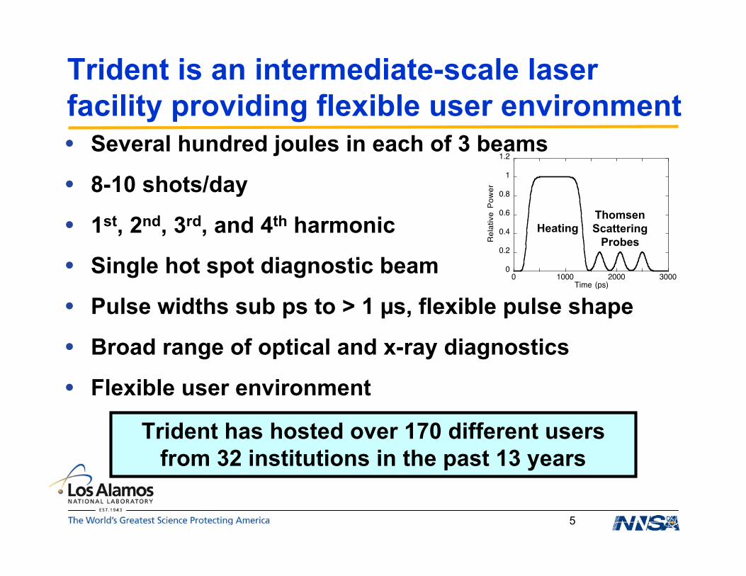
• Several hundred joules in each of 3 beams
• 8-10 shots/day
• 1st, 2nd, 3rd, and 4th harmonic
• Single hot spot diagnostic beam
• Pulse widths sub ps to > 1 µs, flexible pulse shape
• Broad range of optical and x-ray diagnostics
• Flexible user environment
Trident is an intermediate-scale laserfacility providing flexible user environment
Trident has hosted over 170 different usersfrom 32 institutions in the past 13 years
0
0.2
0.4
0.6
0.8
1
1.2
0 1000 2000 3000
Re
lative
P
ow
er
Time (ps)
HeatingThomsenScattering
Probes

6
TRIDENT is a very versatile facility enablingscience, technology & technique development
0
100
200
300
400
500
600
700
800
En
erg
y (J
)
Pulsewidth100 fs 1 ps 1 ns 1 µs
TEX Goal
527 nm
1054 nm
BoostTHz EMP
Fast Ignition Ion Generation
X-Ray RadiographyProton Radiography
Detector Development LPI SSAA Program
X-Ray Generation Diagnostic Development
Dynamic Materials Properties
Dynamic Materials PropertiesFlyer-Plate DriveSNM Properties
• Pulse length variable over 6.5 orders of magnitude
7
Trident facility has 2 target chambers & manydiagnostics in place
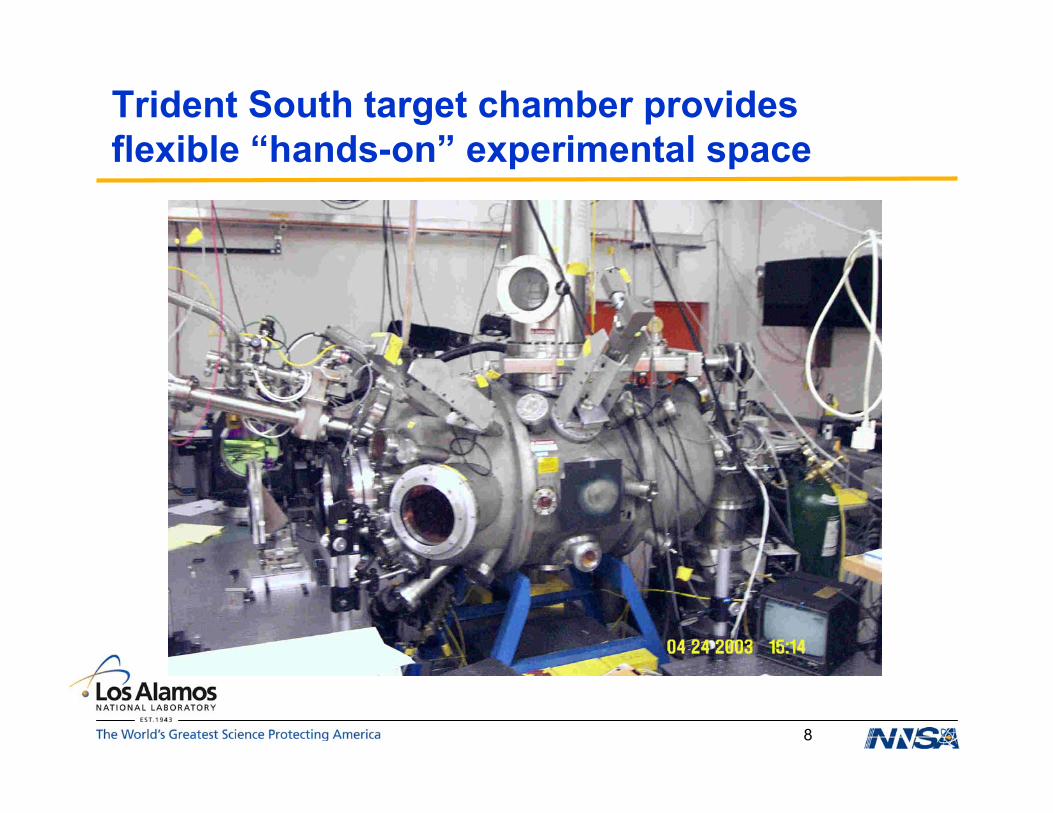
• South target chamber - elliptical shape, lots of room
• North target chamber - sphere; TIM attached
• West target chamber - being designed– Optimized for short-pulse experiments - 12 sided, cylindrical,
lots of access
• Multiple target chambers allow– Two experiments on same laser pulse– Flexible set up - choose optimal geometry for physics– Efficient experimental preparations (parallel work)
• Full range of laser diagnostics on every short-pulseshot
8
Trident South target chamber providesflexible “hands-on” experimental space

9
Trident North target chamber provides compatibleport configurations for NIF & Omega diagnostics
10
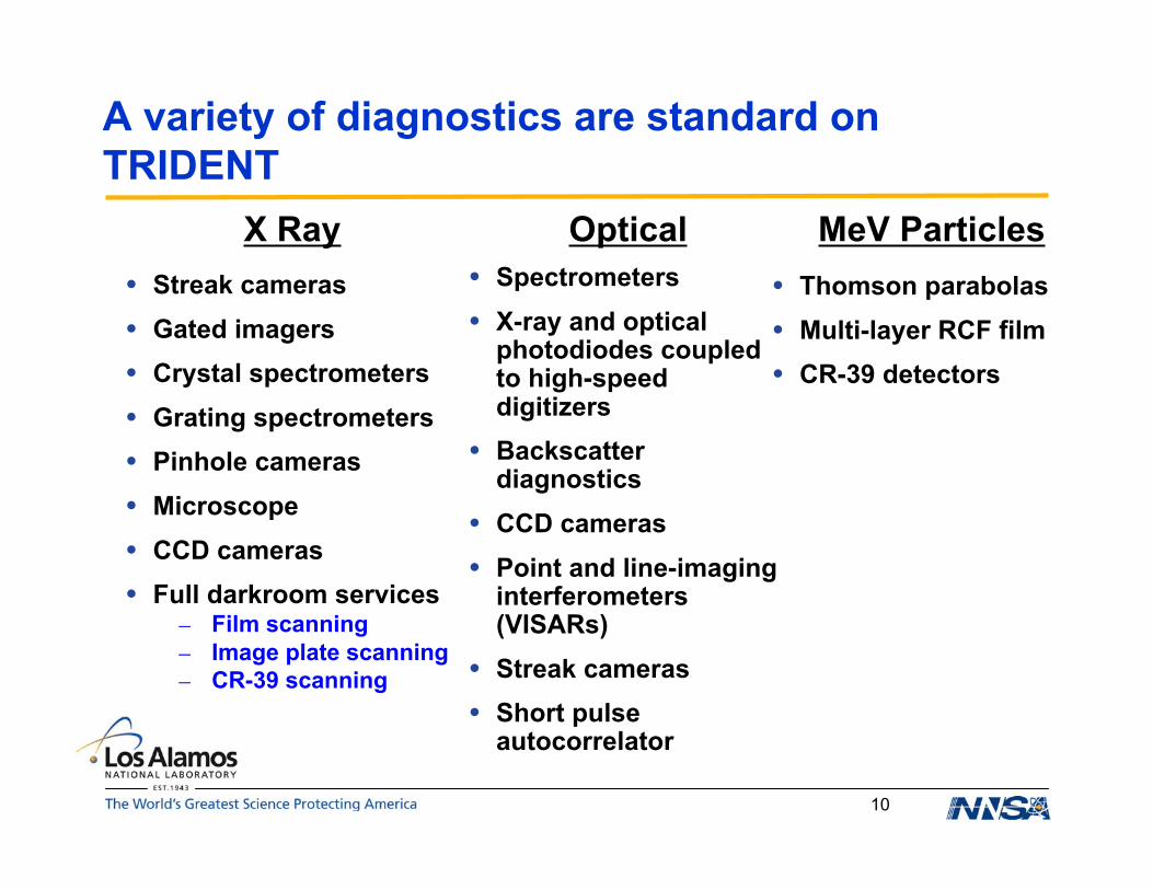
A variety of diagnostics are standard onTRIDENT
• Streak cameras• Gated imagers• Crystal spectrometers• Grating spectrometers• Pinhole cameras• Microscope• CCD cameras• Full darkroom services
– Film scanning– Image plate scanning– CR-39 scanning
• Spectrometers• X-ray and optical
photodiodes coupledto high-speeddigitizers
• Backscatterdiagnostics
• CCD cameras• Point and line-imaging
interferometers(VISARs)
• Streak cameras• Short pulse
autocorrelator
X Ray Optical MeV Particles• Thomson parabolas• Multi-layer RCF film• CR-39 detectors

11
Trident enhancement will increase laser energyin short-pulses
• Increased energy in short-pulse beam to > 200 J
• Added vacuum compressor with large dielectricgratings
• New beam transport, active beam quality control withadaptive optics, beam diagnostics
• High-quality front-end
• Schedule for completion in early summer
12
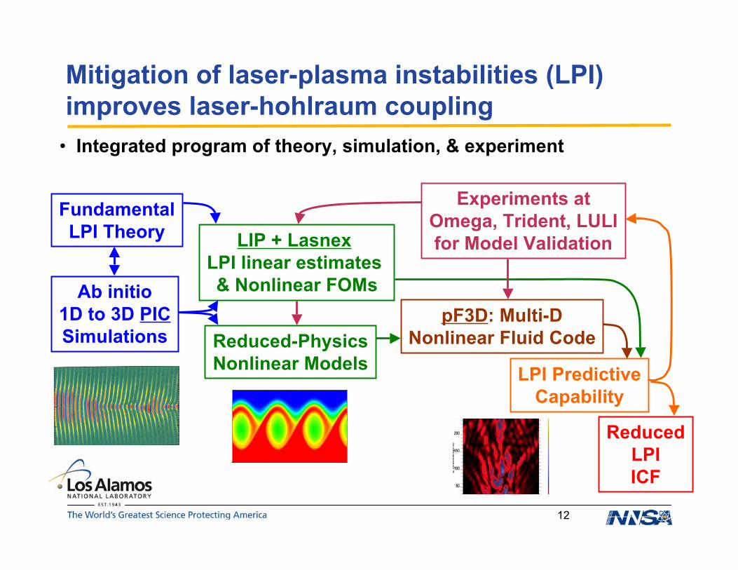
Mitigation of laser-plasma instabilities (LPI)improves laser-hohlraum coupling
• Integrated program of theory, simulation, & experiment
0 10 20 30 40
2.0
2.5
3.0
3.5
4.0
Ab initio1D to 3D PICSimulations
FundamentalLPI Theory
Reduced-PhysicsNonlinear Models
Experiments atOmega, Trident, LULIfor Model ValidationLIP + Lasnex
LPI linear estimates & Nonlinear FOMs
pF3D: Multi-DNonlinear Fluid Code
LPI PredictiveCapability
ReducedLPIICF

13
Preliminary VPIC 3D LPI simulation showsgrowth of filamentary structures
Simulation parameters:5.75x10⁸ cells1.8x1010 particles32 particles/cell1008 processors onLightning/BoltTe=700 eV, λDe=0.037 µmI0=1x10¹⁶ W/cm2, λ0=527 nm
Simulation domain
Longitudinal E field
18 µm90.4 µm
18 µm
Shaded regionshown below
laser
ωpet=842 ωpet=1894Isosurfaces at Ex= +/- 0.025 Isosurfaces at Ex= +/- 0.03
14
Short-pulse, single-hot-spot experiments givefundamental understanding
• Particle-in-Cell (PIC) codes only simulate a few ps
• SRS gain time is of order a ps
• “Single-hot-spot” (SHS) experiments use a very cleanoptical beam that mimics a single speckle in asmoothed laser beam
• “Short-pulse” experiments use pulses of order ≈ 5 ps
• High-quality diagnostics– Electron temperature and density, reflectivity, transmission
• Combining these elements gives a clean quantitativetest of fundamental modeling of SRS
15
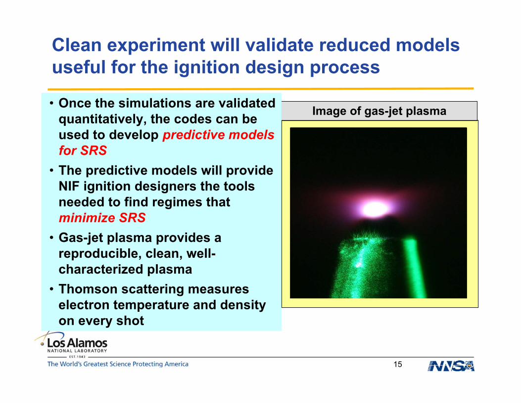
Image of gas-jet plasma
Clean experiment will validate reduced modelsuseful for the ignition design process
• Once the simulations are validatedquantitatively, the codes can beused to develop predictive modelsfor SRS
• The predictive models will provideNIF ignition designers the toolsneeded to find regimes thatminimize SRS
• Gas-jet plasma provides areproducible, clean, well-characterized plasma
• Thomson scattering measureselectron temperature and densityon every shot
16
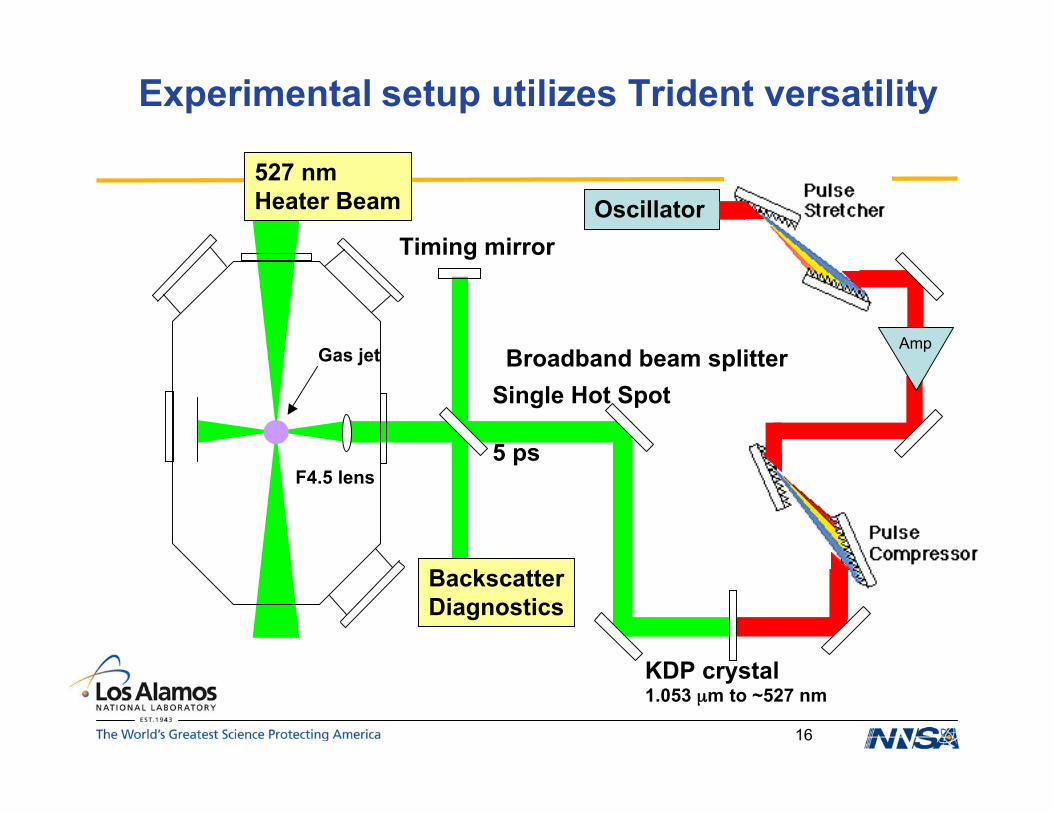
Experimental setup utilizes Trident versatility
BackscatterDiagnostics
Oscillator527 nmHeater Beam
KDP crystal1.053 µm to ~527 nm
Broadband beam splitter
Timing mirror
F4.5 lens
Gas jet Amp
Single Hot Spot
5 ps
17
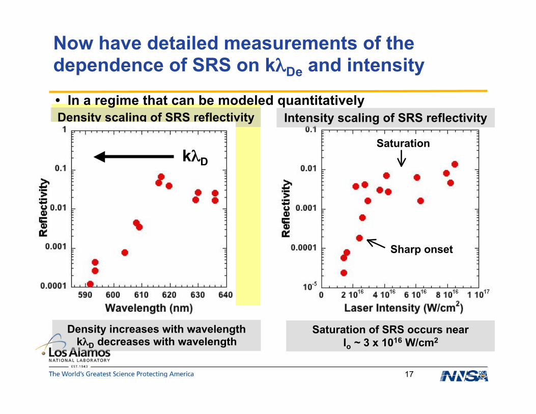
Now have detailed measurements of thedependence of SRS on kλDe and intensity
Density scaling of SRS reflectivity
Io = 1.6 - 2.2 x 10¹⁶ W/cm2
Density increases with wavelengthkλD decreases with wavelength
Intensity scaling of SRS reflectivity
Saturation of SRS occurs nearIo ~ 3 x 10¹⁶ W/cm2
Sharp onset
SaturationkλD
• In a regime that can be modeled quantitatively
18
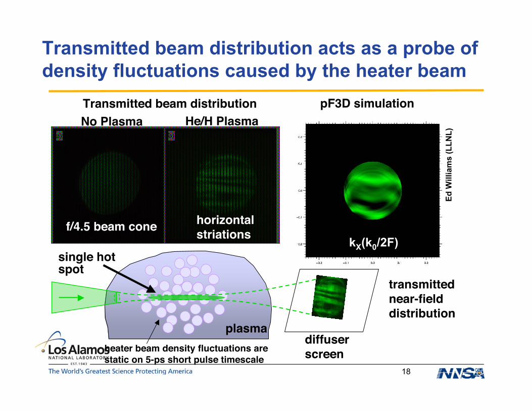
Transmitted beam distribution acts as a probe ofdensity fluctuations caused by the heater beam
No Plasma He/H PlasmapF3D simulationTransmitted beam distribution
plasmaheater beam density fluctuations arestatic on 5-ps short pulse timescale
f/4.5 beam cone
single hotspot
transmittednear-fielddistribution
diffuserscreen
horizontalstriations kX(k0/2F)
Ed W
illia
ms
(LLN
L)

19
Mitigation: Addition of high-Z dopant decreasesStimulated Raman Scattering (SRS)
Theory/model predictions Omega results showingreduced SRS with Xe
• Adding a high-Z dopant (Xe) decreases the thermal filamentation threshold• More filamentation increases “beam spray,” reducing the speckle/correlation length and resultant SRS gain length
IncreasedIncreasedHigh-ZHigh-Zdopantdopant
Wavelength (nm)
Tim
e (n
s)
0% Xe
400 450 500 550 600 650
2.0
1.5
1.0
0.5
0.0
2.0
1.5
1.0
0.5
0.0
9% Xe
20
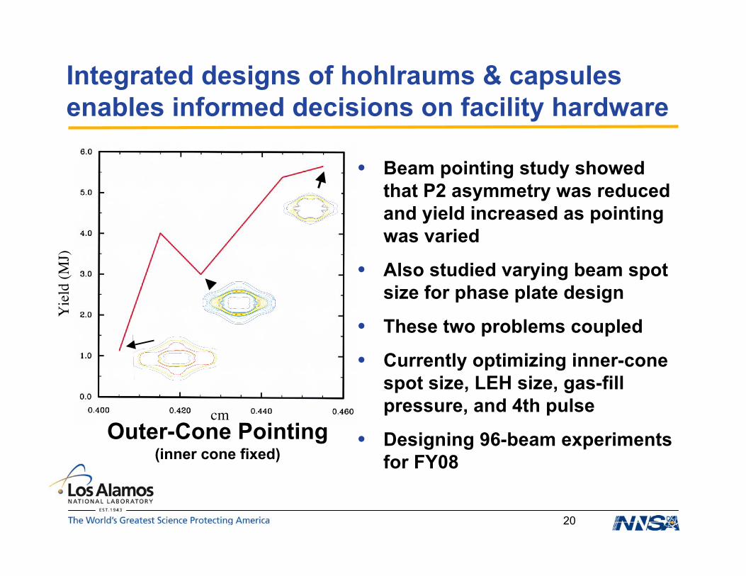
Integrated designs of hohlraums & capsulesenables informed decisions on facility hardware
• Beam pointing study showedthat P2 asymmetry was reducedand yield increased as pointingwas varied
• Also studied varying beam spotsize for phase plate design
• These two problems coupled
• Currently optimizing inner-conespot size, LEH size, gas-fillpressure, and 4th pulse
• Designing 96-beam experimentsfor FY08
Yie
ld (M
J)
cmOuter-Cone Pointing
(inner cone fixed)
21
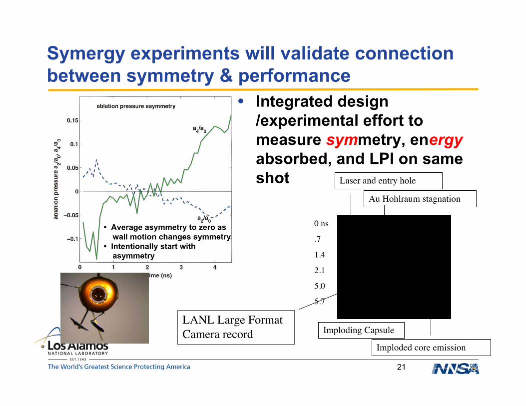
Symergy experiments will validate connectionbetween symmetry & performance
• Integrated design/experimental effort tomeasure symmetry, energyabsorbed, and LPI on sameshot
• Average asymmetry to zero aswall motion changes symmetry
• Intentionally start withasymmetry
Laser and entry hole
Imploding Capsule
0 ns
.7
1.4
2.1
5.0
5.7
LANL Large FormatCamera record
Imploded core emission
Au Hohlraum stagnation

22
Understanding, to a fine degree, berylliumproperties is necessary for ignition
• Choosing a robust ignition configuration requires detailedknowledge of material response, particularly melt pressure
• Materials with grains can cause shock roughness– Degrade implosion by enhancing mixing
Dynamic ellipsometry showing optical detection of bandstructure effect of a phase change (melting) in Sn through LiFrelease window.
X-ray diffraction from Ga crystal showing detection of a phasechange (melting). Shock: laser ablation.
Phase changes
23
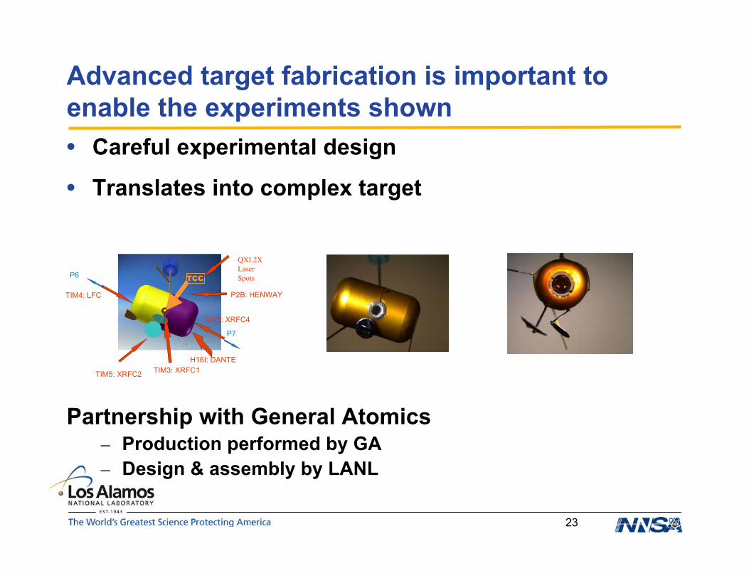
Advanced target fabrication is important toenable the experiments shown• Careful experimental design
• Translates into complex target
Partnership with General Atomics– Production performed by GA– Design & assembly by LANL
TCCP6
P7
TIM5: XRFC2
H16I: DANTE
P2B: HENWAY
TIM6: XRFC4
TIM4: LFC
TIM3: XRFC1
QXI,2XLaserSpots
24
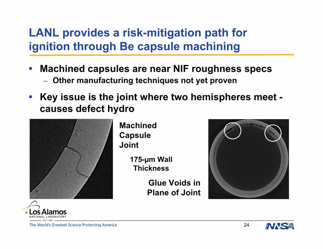
LANL provides a risk-mitigation path forignition through Be capsule machining
• Machined capsules are near NIF roughness specs– Other manufacturing techniques not yet proven
• Key issue is the joint where two hemispheres meet -causes defect hydro
MachinedCapsuleJoint
Glue Voids inPlane of Joint
175-µm WallThickness
25
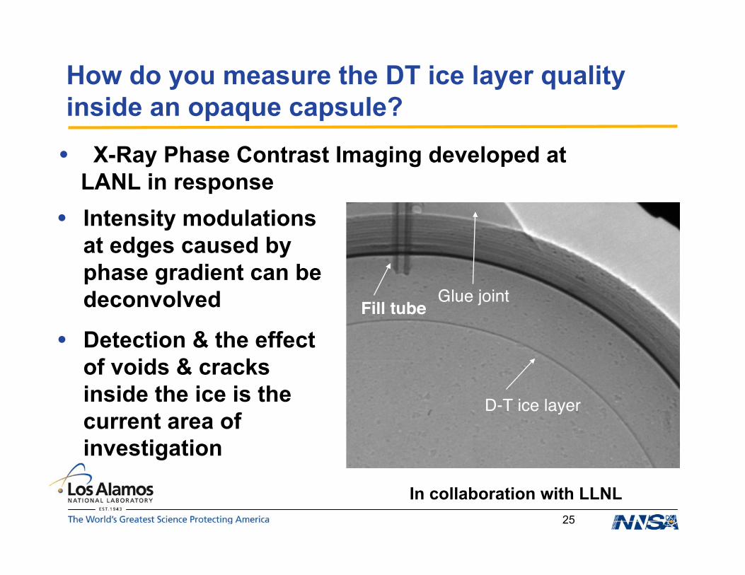
How do you measure the DT ice layer qualityinside an opaque capsule?
• Intensity modulationsat edges caused byphase gradient can bedeconvolved
• Detection & the effectof voids & cracksinside the ice is thecurrent area ofinvestigation
D-T ice layer
Fill tubeGlue joint
• X-Ray Phase Contrast Imaging developed atLANL in response
In collaboration with LLNL
26
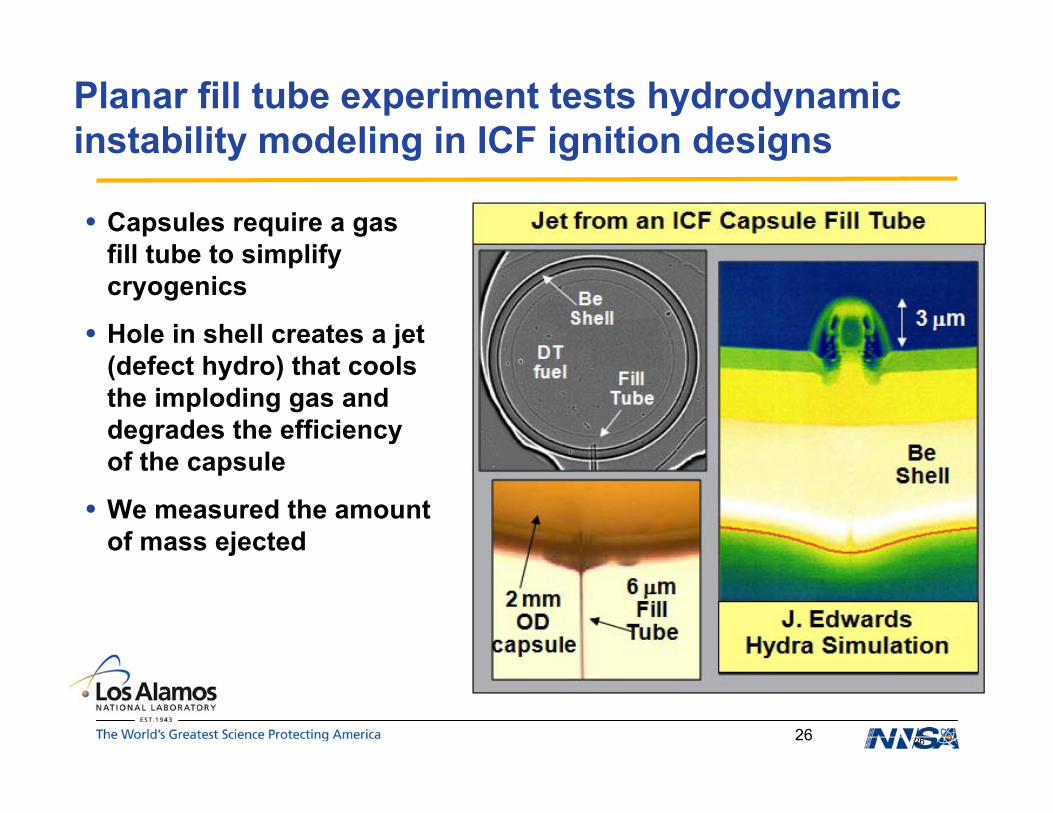
Planar fill tube experiment tests hydrodynamicinstability modeling in ICF ignition designs
26
• Capsules require a gasfill tube to simplifycryogenics
• Hole in shell creates a jet(defect hydro) that coolsthe imploding gas anddegrades the efficiencyof the capsule
• We measured the amountof mass ejected

27
Experiment measures jet mass and compares tosimulations
27
50 mg/ccCRF foam
200 µm thickBeCu(3%)washer
100 µm thickBeCu(3%) ablator
20-100 µmdiameter hole
• Gold hohlraum is heatedto 200 eV bu the laser drivebeams• Radiation ablates one sideof the Be disk launching ashock• Radiation travels down thehole, ablating Be materialfrom the sides of the walls• The shock breaks into thehole jetting more Bematerial forward. Thisprocess forms the Be jetthat is observed in theseexperiments.• Jet mass inferred fromradiographs•
Hohlraum
Laser DriveGold Cone(diagnostic shield)

28
Including a small amount of preheatis required to match observations
28
177 µm230 µm
330 µm
0 µm
False color radiograph
Pedestal
Jet
Shock
Simulated Radiograph
Jim
Elli
ott (
LLN
L)
• 50 micron diameter hole• 15 ns after drive• 0.175 eV preheat in simulations
29
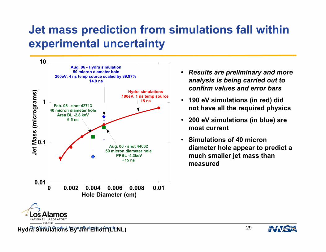
Jet mass prediction from simulations fall withinexperimental uncertainty
29
• Results are preliminary and moreanalysis is being carried out toconfirm values and error bars
• 190 eV simulations (in red) didnot have all the required physics
• 200 eV simulations (in blue) aremost current
• Simulations of 40 microndiameter hole appear to predict amuch smaller jet mass thanmeasured
Hydra Simulations By Jim Elliott (LLNL)
0.01
0.1
1
10
0 0.002 0.004 0.006 0.008 0.01
Je
t M
as
s (
mic
rog
ram
s)
Hole Diameter (cm)
Feb. 06 - shot 4271340 micron diameter hole
Area BL -2.8 keV6.5 ns
Aug. 06 - shot 4466250 micron diameter hole
PPBL -4.3keV~15 ns
Aug. 06 - Hydra simulation50 micron diameter hole
200eV, 4 ns temp source scaled by 89.97% 14.9 ns
Hydra simulations190eV, 1 ns temp source
15 ns
30
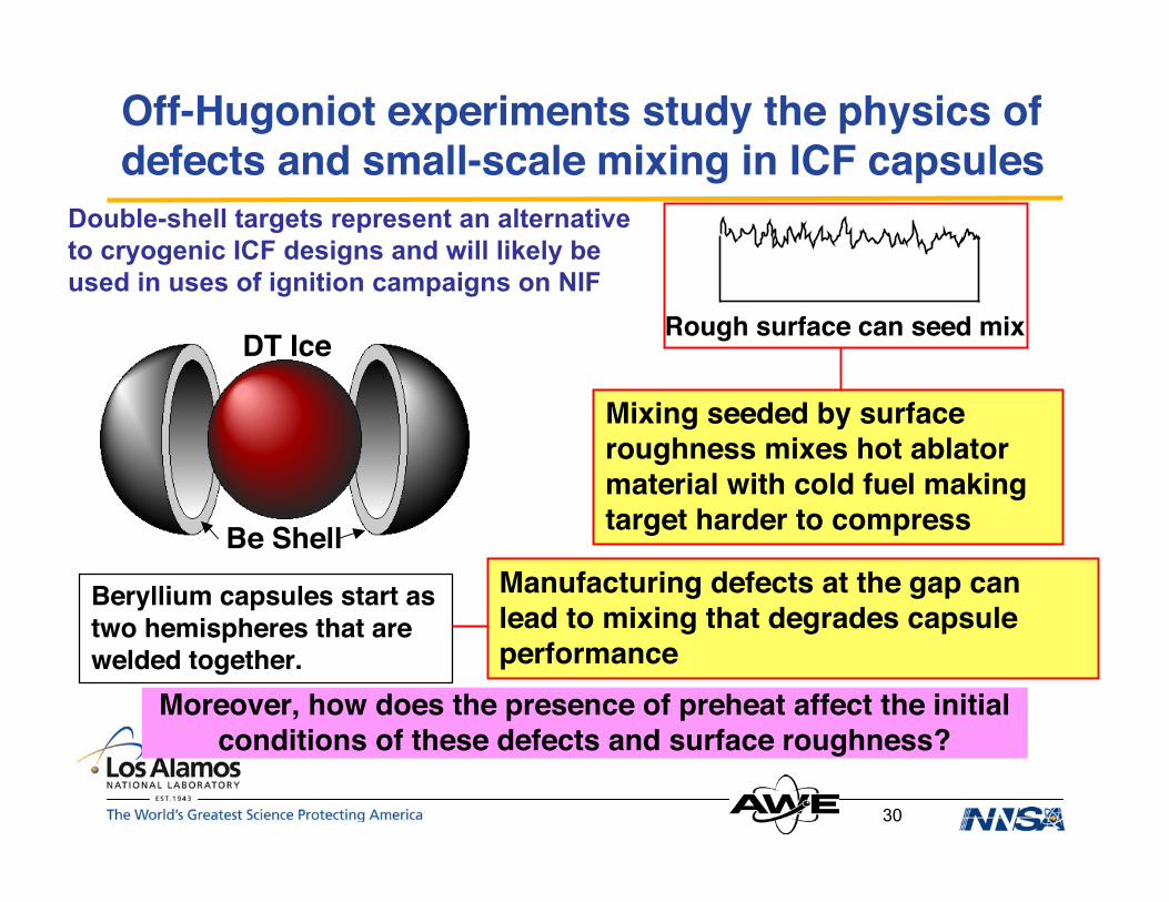
Moreover, how does the presence of preheat affect the initialconditions of these defects and surface roughness?
Off-Hugoniot experiments study the physics ofdefects and small-scale mixing in ICF capsules
Beryllium capsules start astwo hemispheres that arewelded together.
Manufacturing defects at the gap canlead to mixing that degrades capsuleperformance
Mixing seeded by surfaceroughness mixes hot ablatormaterial with cold fuel makingtarget harder to compress
Rough surface can seed mixDT Ice
Be Shell
Double-shell targets represent an alternativeto cryogenic ICF designs and will likely beused in uses of ignition campaigns on NIF

31
Principal Objective: Develop a platform to studythe evolution of defect-driven hydrodynamics
• Study evolution ofheated andindependentlyshockedhydrodynamicsystems
• Experimentprogresses in 4phases:
HeatingShockBacklighterDiagnostic
Backlighter
BafflingCone
Ta ApertureThin SnCoating
Beryllium Housing
EpoxyAblator
Epoxy/FoamPackage
HeatingBeams
Shock DriveBeams
32
43731
42009 4201842005
43729
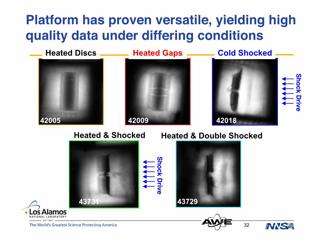
Platform has proven versatile, yielding highquality data under differing conditions
Cold Shocked
Heated & Shocked
Heated Discs Heated Gaps
Heated & Double Shocked
Shock Drive
Shock Drive

33
Highly resolved density profiles provide tightconstraint for PETRA-NYM EoS models
With the EoS model constrained, PETRA-NYM accuratelycaptures the key physical features for preheated defects
PETRA-NYM quantitatively matches horizontal expansion.Vertical evolution is qualitatively similar.
34
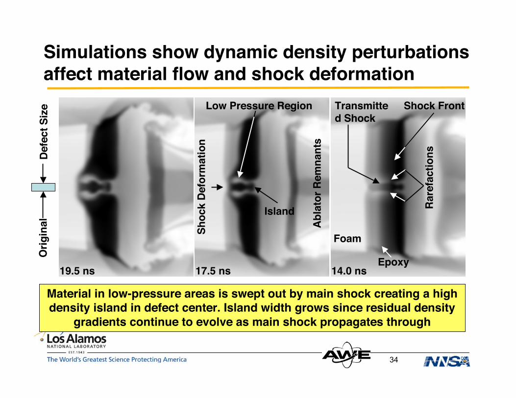
Simulations show dynamic density perturbationsaffect material flow and shock deformation
19.5 ns 17.5 ns 14.0 ns
Shock Front
Abla
tor R
emna
nts
Rare
fact
ions
Transmitted Shock
Epoxy
FoamShoc
k De
form
atio
n
Low Pressure Region
Material in low-pressure areas is swept out by main shock creating a highdensity island in defect center. Island width grows since residual density
gradients continue to evolve as main shock propagates through
Island
Defe
ct S
ize
Orig
inal
35
Defect-driven hydrodynamic experiments testmodeling and margins of ignition capsules
• These experiments study the impact ofmanufacturing defects on ICF capsule performanceby providing quantitative data for hydrodynamicscode validation in complex systems
• The presence of heated defects results in dynamicdensity variations that adversely affect shockmorphology
• The spatial extent of these variations are much largerthan the initial defect
36
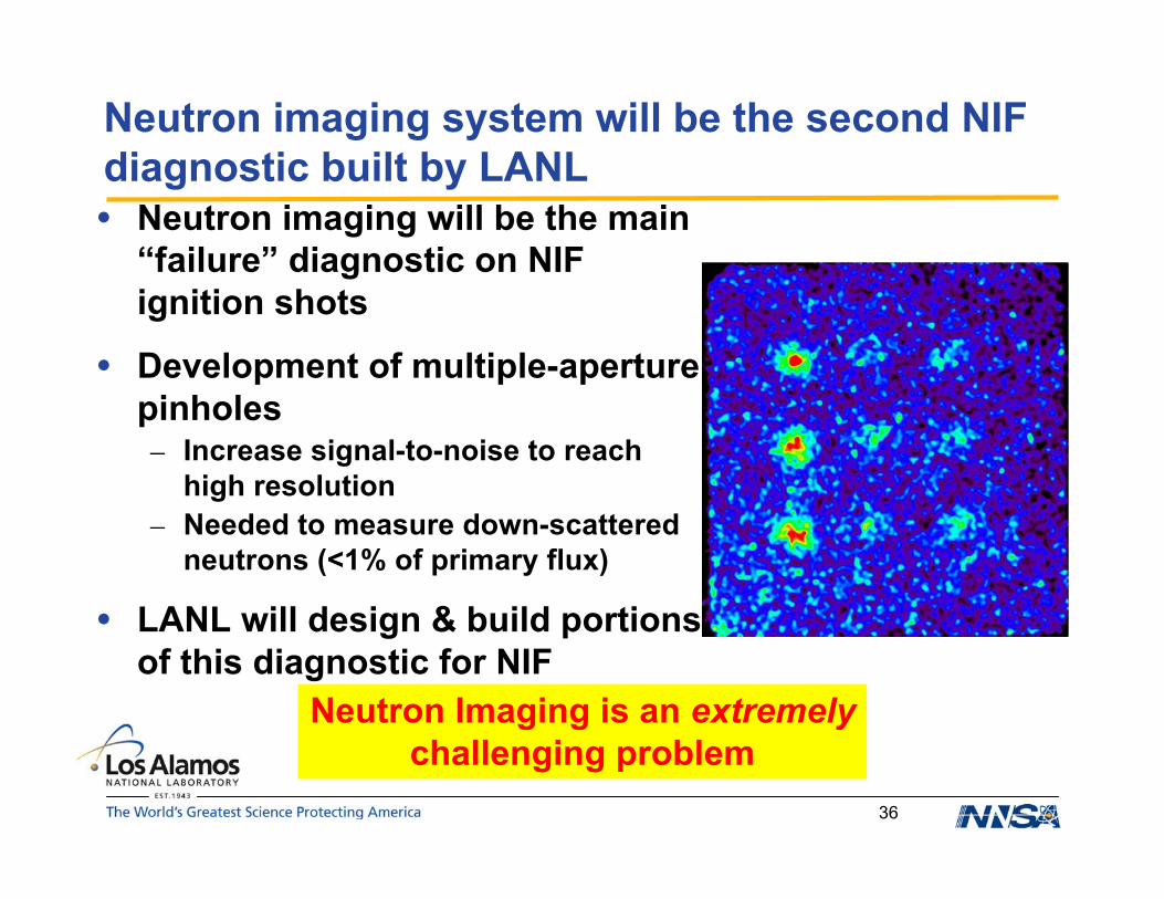
Neutron imaging system will be the second NIFdiagnostic built by LANL• Neutron imaging will be the main
“failure” diagnostic on NIFignition shots
• Development of multiple-aperturepinholes– Increase signal-to-noise to reach
high resolution– Needed to measure down-scattered
neutrons (<1% of primary flux)
• LANL will design & build portionsof this diagnostic for NIF
Neutron Imaging is an extremelychallenging problem

37
• Reduces uncertainty in a key modeling parameter
• Burn-history measurement can be made with eitherfusion neutrons or fusion gamma rays
• Neutrons are slow and affected by path
• Gamma rays travel at speed of light
Time of maximum burn is a stringent measureof capsule absorbed energy
γ(16.7 MeV)(12 MeV?) + 5He
0n1(14.1 MeV) + 4He
0.99999
~10-5
D + T

38
Measure the gamma ray by converting to anelectron
• Then record the Cerenkov radiation from electron
Be Converter
W shielding
Secondary mirror
Primary mirror
DetectorAl chamber
CO2
Burn-history measurements can be madewith either fusion neutrons or fusion γ rays.

39
Gas-Cerenkov Detector has same precision ascurrent diagnostics & better time resolution
• Compare GCD with neutron temporal diagnostic - standarddiagnostic but not scalable to NIF
• Ultimate goal is a full-coverage reaction history diagnostic for NIF– Critical for ignition capsule performance assessment
• Essential collaboration with AWE, NSTec, LLE, LLNL
40
Summary
• Providing key contributions to the National IgnitionCampaign
• Our program is focused on exploiting– LANL strengths– Key areas for ignition– Leveraging towards the future
• Concentrating on– Laser-plasma interactions– Ablator material science– Symergy– Defect-driven hydrodynamics– Neutron diagnostics– Trident laser laboratory now being upgraded to 200 TW