Inelastic transient dynamic analysis of three-dimensional problems by BEM
20
INTERNATIONAL JOURNAL FOR NUMERICAL METHODS IN ENGINEERING, VOL. 29, 371-390 (1990) INELASTIC TRANSIENT DYNAMIC ANALYSIS OF THREE-DIMENSIONAL PROBLEMS BY BEM s. AHMAD* AND P. K. BANERJEE‘ Department of Civil Engineering, State University of New York at Buffalo, Buffalo, New York 14260, U.S.A. SUMMARY A direct Boundary Element formulation and its numerical implementation for inelastic transient dynamic analysis of three-dimensional solids is presented. The formulation is based on an initial stress approach and is the first ever of its kind in the field ofrthe Boundary Element Method. This formulation employs the Navierzauchy equation of motion, Graffis dynamic reciprocal theorem, Stokes’ fundamental solution and the Divergence theorem, together with Kinematical and Constitutive equations to obtain the pertinent integral equations of the problem in the time domain within the context of small displacement theory of elastoplasticity. The boundary integral equations are cast in an incremental form, in which elastoplastic relations of the incremental type are used for the material description. These equations are then solved using a time-stepping algorithm in conjunction with an iterative solution scheme to satisfy the constitutive relations. Higher order shape functions are used to appraximate the field quantities in space as well as in time. Finally, the applicability of this methodology is demonstrated by presenting a few example problems. INTRODUCTION Dynamic analysis of engineering problems involving solids which exhibit non-linear material behaviour has been a subject of intense research for the last two decades. For these problems, because of their complexity, closed form analytical solutions are almost impossible to obtain and hence numerical methods have been invariably used. For non-linear dynamic analysis, the Finite Element Method (FEM) has been the most widely used technique since it is the most versatile of all the existing numerical methods. However, the deficiency of the FEM in handling dynamic problems involving semi-infinite and infinite media is well known. In recent years, the Boundary Element Method (BEM) has emerged as a powerful tool for solving problems of continuum mechanics. It has been successfully used for the sojution of a very wide range of physical problems, as it is evident in a number of textbooks on the subject, e.g. Banerjee and Butterfield,’ Mukherjee,2 Liggett and L ~ u , ~ Brebbia el aL4 For linear elastic problems under static or dynamic loading, the BEM has a number of distinct advantages over the FEM, as explained in the above mentioned books and in Banerjee et ~l.,~ Banerjee and Ahmad,6 Ahmad,’ etc. Some of these advantages for transient dynamic problems are: (i) accurate and efficient solutions of problems involving a semi-infinite or infinite domain, because the radiation condition at infinity is automatically satisfied by the Stokes’ fundamental Assistant Professor + Professor 0029-5981/90/020371-20%10.00 0 1990 by John Wiley & Sons, Ltd. Received 16 June 1988 Revised 5 July 1989
-
Upload
independent -
Category
Documents
-
view
2 -
download
0
Transcript of Inelastic transient dynamic analysis of three-dimensional problems by BEM

INTERNATIONAL JOURNAL FOR NUMERICAL METHODS I N ENGINEERING, VOL. 29, 371-390 (1990)
INELASTIC TRANSIENT DYNAMIC ANALYSIS OF THREE-DIMENSIONAL PROBLEMS BY BEM
s. AHMAD* AND P. K. BANERJEE‘
Department of Civil Engineering, State University of New York at Buffalo, Buffalo, N e w York 14260, U.S.A.
SUMMARY
A direct Boundary Element formulation and its numerical implementation for inelastic transient dynamic analysis of three-dimensional solids is presented. The formulation is based on an initial stress approach and is the first ever of its kind in the field ofrthe Boundary Element Method. This formulation employs the Navierzauchy equation of motion, Graffis dynamic reciprocal theorem, Stokes’ fundamental solution and the Divergence theorem, together with Kinematical and Constitutive equations to obtain the pertinent integral equations of the problem in the time domain within the context of small displacement theory of elastoplasticity. The boundary integral equations are cast in an incremental form, in which elastoplastic relations of the incremental type are used for the material description. These equations are then solved using a time-stepping algorithm in conjunction with an iterative solution scheme to satisfy the constitutive relations. Higher order shape functions are used to appraximate the field quantities in space as well as in time. Finally, the applicability of this methodology is demonstrated by presenting a few example problems.
INTRODUCTION
Dynamic analysis of engineering problems involving solids which exhibit non-linear material behaviour has been a subject of intense research for the last two decades. For these problems, because of their complexity, closed form analytical solutions are almost impossible to obtain and hence numerical methods have been invariably used. For non-linear dynamic analysis, the Finite Element Method (FEM) has been the most widely used technique since it is the most versatile of all the existing numerical methods. However, the deficiency of the FEM in handling dynamic problems involving semi-infinite and infinite media is well known.
In recent years, the Boundary Element Method (BEM) has emerged as a powerful tool for solving problems of continuum mechanics. It has been successfully used for the sojution of a very wide range of physical problems, as it is evident in a number of textbooks on the subject, e.g. Banerjee and Butterfield,’ Mukherjee,2 Liggett and L ~ u , ~ Brebbia el aL4
For linear elastic problems under static or dynamic loading, the BEM has a number of distinct advantages over the FEM, as explained in the above mentioned books and in Banerjee et ~ l . , ~ Banerjee and Ahmad,6 Ahmad,’ etc. Some of these advantages for transient dynamic problems are: (i) accurate and efficient solutions of problems involving a semi-infinite or infinite domain, because the radiation condition at infinity is automatically satisfied by the Stokes’ fundamental
Assistant Professor + Professor
0029-5981/90/020371-20%10.00 0 1990 by John Wiley & Sons, Ltd.
Received 16 June 1988 Revised 5 July 1989

312 S. AHMAD AND P. IC. BANERJEE
solution; (ii) reduction of the dimensionality of the problem by one, resulting in a discretization of just the surface of the domain instead of the whole domain (as required in the FEM). However, for problems with material non-linearity, in addition to the boundary discretization, an interior discretization of a small part of the domain where non-linear behaviour is expected becomes necessary. Since the number of unknowns in the resulting algebraic system of equations depends only on the boundary discretization, still a considerable reduction in the size of the problem is achieved. Moreover, stresses can be determined more accurately by the BEM in a pointwise fashion than they can be obtained by the FEM. The accuracy of stress computation is of great importance in a non-linear analysis, because the inelastic strain rates, which are to be calculated during the analysis, are proportional to stress ratios. This advantage of the BEM is evident in elastoplasticity and viscoplasticity under static or quasistatic loadings as explained in Banerjee and Butterfield', Mukherjee,z etc. The only major disadvantage of the BEM is that the final system matrix is full and non-symmetric, thereby the solution cost is somewhat increased.
All of the existing works on dynamic analysis by the BEM are based on the assumption of linear elastic behaviour, and most of them assume steady-state (time-harmonic) conditions. However, for realistic engineering problems, steady-state conditions and linear elastic behaviour are at best a first order approximation. For a truly transient process, it is thus mandatory to consider time dependent response and non-linear behaviour.
The work described in this paper (previously reported in a non-archival report for NASA contract NAS3-23697 by Wilson and Banerjee,' in the Ph.D. dissertation of Ahmad7 and through private communication to Manolis and Beskosg ) represents the first ever effort towards the development of a general numerical methodology for solving non-linear transient dynamic problems by using the BEM. This work essentially combines the knowledge and experience from our recent work in time domain transient el as to dynamic^^*^*'^.' and static elastoplas- ticity. ''- l 4
GOVERNING EQUATIONS OF DYNAMIC PLASTICITY
In the context of theory of small deformation, the equation of motion for an elastoplastic body, having a volume V enclosed by a surface S, experiencing motion under the influence of dynamic loading can be expressed as
AaijSj + Ab, - pAu, = 0 in V where
Aoi j = Aaij(x, T ) are the incremental components of the stress tensor, Ahi = Ab,(x, T ) are the incremental components of the body force vector, Aui = Aui(x, T) are the incremental components of the displacement vector, p = the mass density of the body, x = position vector
and commas indicate differentiation w.r.t. spatial co-ordinates, dots indicate differentiaion w.r.1. time 'T ' , repeated indices imply summation convention and indices receive the values 1, 2, 3 (Cartesian co-ordinates) for three-dimensional problems.
In a well posed boundary-initial value problem, the equation of motion is accompanied by appropriate boundary and initial conditions. The displacements and tractions satisfy the bound- ary conditions
Aui(x, T ) = Aqi(x, T ) on S ,
Ati (x , T ) = Api(x, T) on S, (2b)

TRANSIENT DYNAMIC ANALYSIS BY BEM 373
and the following initial conditions,
Aui(x, T = 0) = AUp(x) in V
brii(x, T = o)= A@(x) in v where
s = s, + s,, Ati are the incremental components of the traction vector, Aqi and Api are the incremental prescribed displacements and tractions, respectively, and AUp and A U p are the incremental initial values of displacement and velocity, respectively.
The stress and traction on the boundary surface of the body are related via the Cauchy traction relation as
Ati = Aaijnj (3)
and for small deformations strain is related to displacement via the' following kinematical relationship:
A E ~ , = O . ~ ( A U , , ~ + A ~ j , i ) (4)
In equation (3), nj are the components of the unit outward normal vector to the boundary surface S.
The incremental strain tensor Aqj can be decomposed into an elastic strain rate tensor A&rj and an inelastic strain rate tensor
A€ I J . = Ace. ,I +.A&?. CJ ( 5 )
The elastic strain is directly related to stress aij through the elastic constitutive relations
Aaii = D;jki where
D;jki = A6,,6ki + 2/.dik6ji (7)
dij is the Kronecker delta, and A and p are Lame constants.
strain, i.e. The inelastic strain rate, by definition, is the difference between the total strain and the elastic
A&
314 S. A H M A D A N D P. K. BANERJEE
been used for an inelastic static p r ~ b l e m . ' ~ ' ~ - ' ~ Under zero initial conditions and zero body forces, the boundary integral equation for inelastic transient dynamics can be expressed as
ci j (S)Aui(S, T ) = CGij(x,S, T ) * A t i ( x , T ) - F i j ( x , L T ) * A u i ( x , r ) l d S ( x ) ss +
where * denotes convolution
Bi, j ( x , 6, T) * ~ a g ( x , ~ ) d ~ ( x ) (1 1)
G i j * A t i = G i j ( x , T ; t , r ) A t i ( x , r ) d 7
6 and x are the space positions of the receiver (field point) and the source (source point), respectively,
B. = G..
The fundamental solutions G , and Fij are the displacement ui and traction t i , respectively, at a point x at time T due to a unit force vector applied at a point 6 at a preceding time T. These functions are listed in Appendix I.
Since constitutive equations expressing the material behaviour in the inelastic range are given only in incremental form (equation (9)), it is necessary for the incremental boundary integral equations, for the inelastic transient dynamic problem, to be integrated over the entire loading history. In the elastodynamic problem, this is automatically achieved through the Reimann convolution of incremental boundary displacements and surface tractions as well as the initial stress histories as exemplified in equation (1 1).
s: I l l 1 J . l
Stresses at interior points
The integral equations for the stress increment at an interior point can be obtained by taking derivatives of the boundary integral equation for an interior point (i.e. equation (1 1) with cij = S i j ) , and using incremental constitutive equation (9) and kinematic equations (4) and (5). These equations have the form
ACjk(6, T ) = [G;jk(X,S, T)*Ari(x, T)-Fyjk(X,C, T ) * A u i ( x , T)]dS ss + J: & , j k ( X , 5, T ) * A a g ( x , T)dV + JiljkAfJ?l(S, T ) (12)
The functions Gyjk, F;jk, B;,jk and J i l j e are defined in Appendix 11. In equation (12), the volume integral is singular, therefore it must be evaluated in the sense of
( V - V,) with limit V, -P 0. Because of the singularity, the tensor Jiljk is the so-called stress jump term obtained from the analytical treatment of the integral over V,. This jump term is the same as that of static plasticity and is independent of the size of the exclusion VE, provided the initial stress distribution is homogeneous within V."-14
Stresses at boundary points
The stresses (incremental) at the boundary points and at points very close to the boundary cannot be evaluated by using equation (12), owing to the strongly singular nature of the integrals involved. However, the equations for obtaining stresses (incremental) at boundary points can be

TRANSIENT DYNAMIC ANALYSIS BY BEM 315
constructed by combining the constitutive equation, the directional derivatives of the displa- cement vector and the values of the field variables in an accurate matrix formulation. Using this scheme, the incremental stresses at boundary point tb can be obtained by coupling the following set of equations:
Aaij(Sb, T ) =ICLaijAurn,m(Sb, T ) + p{Aui,j(Sb, TI + AUj,i(Sbl T I } ] - Aa?j(Sb, T ) (134
Ati(Sb, T)= Aaij(Sb, T)nj(Sb) (13b)
where ‘1. is a set of local axes at the field point (5’). The above equations can be combined together and written in a matrix form as
CWl {PI = (41 (14)
where [W] is a 15 x 15 matrix which contains unit normals, a 3 x 3 unit matrix and material constants; { p } is the unknown vector of Aaij and aAui/atj; and {q} is a vector containing the known tractions Ati and local derivatives of the displacements Aui.
The displacement Aui and traction Ati at a boundary point gb can be expressed in terms of the nodal values as
Aui(Sb) = N,Auq (154
Ati(Sb)= NaAt: (1 5b) where Nu are the element shape functions, and Auq and At; are the nodal values of displacements and tractions, respectively.
By making use of the set of equations (1 5), the right hand side of equation (14) can be written as
where [ E l is a 15 x 48 matrix of shape functions and derivatives of shape functions; and { g } is a vector of incremental nodal tractions and displacements over all of the local element nodes.
Inverting matrix [ W ] and utilizing equation (16), the set of equations (14) can be rearranged to form
AOjk(Sb, T ) = Gjk&(Sb, T ) - c j k A u i ( & b , T ) + RljkAa?l(Sb, T ) (17)
Equation (17) will be used to evaluate the incremental stresses on the boundary points. It should be noted that this equation is free of any integration and time convolution. The bars on the functions in equation (17) indicate that these functions are different from their counterparts in equation (1 2).
CONSTITUTIVE MODEL
In dynamic plasticity, the choice of an appropriate constitutive model depends largely on the material properties and the loading conditions of the problem in hand. For this reason various constitutive models have been used for dynamic plasticity. However, for simplicity, the von Mises model with isotropic variable hardening is used here.
In this model, the behaviour in the elastoplastic region is governed by the stress-strain relations
V 3si j Aaij = 2p AEij + -6ijAEkk - [ 1 - v 2ai ( l + H / 3 p )

376 S. A H M A D A N D P. K. BANERJEE
where Aaij = D;Tk,AEk, = incremental stress tensor, D:Tk, = incremental elastoplastic material modulus, p = elastic shear modulus, v = Poisson’s ratio, a. = uniaxial yield stress = J3sijsij/2, S i j = deviatoric stress = aij - hijakkf3 and H = plastic-hardening modulus, the current slope of the uniaxial plastic stress-strain curve.
The present implementation is such that any other constitutive model can be included without major difficulty.
NUMERICAL IMPLEMENTATION
The boundary integral equations (1 1) and (12) along with equation (17) provide the formal basis for developing the algorithm for the inelastic transient dynamic analysis. However, the initial stresses AoYj defined in these equations are not known a priori and have to be evaluated by satisfying the constitutive relations (i.e. equation (1 8) for the present work). Thus, equations ( 1 l), (12), (17) and (18) can be regarded as a coupled system of non-linear equations. Analytical solution of such a system is not possible and therefore it has to be done numerically.
The numerical implementations of integral equations essentially consist of: discretization of the surface of the body, interior discretization of the part of the domain where inelastic material behaviour is expected, numerical integration, assembly and the iterative solution of the final system equations.
Details of the numerical schemes for surface discretization, spatial and temporal boundary integrations, spatial volume integration and assembly of system equations can be found in References 5-7, 10, 13 and 14. In this paper, only the discretization and temporal integration of the volume integrals, the time-marching schm, and the iterative solution algorithm used in the present work are presented in detail. However, for completeness a brief description of the rest of the numerical schemes is provided in the following paragraphs.
The surface modelling is done using either 6-noded triangles or 8- or 9-noded quadrilateral elements; the modelling of necessary parts of the domain is done using 20-noded volume cells.
The spatial variation of the field variables over an element or a cell can be either linear or quadratic or a mixture of linear and quadratic. The temporal variation of the field variables can be either linear or constant.
The spatial integration is carried out to a pre-selected three to five digit precision for all integrals. The time integrations at every time step have been done analytically. The details of the temporal integration can be found in References 7 and 10.
DOMAIN INTEGRATION
Since the volume integrals of equations ( 1 1) and (12) related to inelastic stress vanish except in regions of non-linear material response, approximations of interior geometry and field quantities are required only where non-linearity is expected. In the present work, isoparametric 20-noded volume cells are used for approximating the geometry and the variation of initial stresses such that

TRANSIENT DYNAMIC ANALYSIS BY BEM 377
where x i are Cartesian co-ordinates, (Xi), are nodal co-ordinates of the volume cell, N , is a quadratic shape function for the volume cell, p represents the nodal points of the volume cell and an overbar denotes a nodal quantity.
The volume integral of equation ( 1 1) can be then represented as f T P
Bilj(x, T;kb, ~ ) A a ; ( x , ~ ) d V d r J O J v
where
gb is the field point on the boundary (boundary node), x"(q) is the point in cell m, (Ad:);; are the nodal values of incremental initial stress of the mth cell, V, is the mth volume cell and L is the total number of cells.
Similarly, the volume integral of interior stress equation (12) can be expressed as
J o Jv I PT P
In equations (20) and (21), the temporal integration is performed analytically, and is identical to the temporal integration of surface integrals explained in Reference 10.
Time-marching scheme
into N equal time intervals, i.e. In order to obtain the non-linear transient response at a time TN, the time axis is discretized
N TN= nAT
n = l
where AT is the time step.
can be written as Using the definition of time convolution and equation (22), the boundary integral equation ( 1 1)
cijAUi(5, - js [GijAti - FijAui]dSds - IT:-, Iv Bi1 jAa;d v d r
= IT::' [GijAti - FijAui]dSdr + Iv BiljAaedodr (23)
where the integral on the right hand side is the contribution due to past dynamic history. Details of obtaining equation (23) can be found in References 5, 7 and 10.

378 S. AHMAD A N D P. K . BANERJEE
It is of interest that equation (23), like equation (1 l), still remains an exact formulation of the problem since no approximation has yet been introduced. However, in order to solve equa- tion (23), one has to approximate the time variation of the field quantities in addition to the usual approximation of spatial variation. For this purpose, a linear interpolation function is used which is described with the resulting time-stepping algorithm as follows.
The field variables (i.e. displacements, tractions or stresses) are assumed to vary linearly during a time step, i.e.
N
Ui(X, T ) = [M;UY-'(X) + MFU;(X)] (244 n = l
where N is the total number of the time steps, u ; ( x ) and t ; ( x ) represent the spatial variation of ui and t i , respectively, at time T,, M , and M, are the temporal interpolation functions related to local time nodes I and F,I0 and are of the form
where 4 " ( ~ ) = 1 for ( n - l ) A T < T < nAT, and
= 0 otherwise; or
& ( T ) = [ H { ~ - ( n - l ) d T } - H { r - n A T } ] H being the Heaviside function.
Thus, after the usual discretization and integrations" (both time and spatial), the integral equation (24) is transformed into an assembled system equation of the form
[ A : ] { A X N 1 - CBbI { A YN 1 - [GI { ( A a o ) N 1 N
= - 1 [ [ A F + A y - l ] { A X N - n + ' } - [BF + By- ' 3 { A Y N - n + ' } n = 2
+ [CF + C y - ' ] { A c r O } N - n + l 1
[ A b ] { A X N ) = [ B : ] { A Y " ) + [ C ~ ] ( ( A a o ) N } + {RN)
(2W or
( 2 W or
A A X N = A b N + AcN (27)
A and B are the matrices related to the unknown and known incremental displacements and tractions, C is the matrix related to the initial stresses,
where

TRANSIENT DYNAMIC ANALYSIS BY BEM 379
A X and A Y are the vectors of unknown and known incremental displacements and tractions, for A X , A Y and Aa', the superscript denotes time, i.e. at time n, A X " = X" - X"- ', for matrices A, B and C, the superscript denotes the time step when they are calculated, and the subscript denotes the local time node ( I or F), R N is the effect of past dynamic history,
AbN = [ B b ] { A Y N } + { R N }
A = [A:]
AcN = [ C:] { ( A u ' ) ~ } (28c)
(29)
Similarly, the integral equation for stresses can be written in a discretized form as
{ACT"} = [A:],{AXN} + [B: l , {AYN} + [C:],{AO')~} + { R N } ,
or A a N = A, AXN + Ab: + A C r
where A, = [A:],
A b r = [B;],{AYN} + { R N } ,
Acr = [C;],{(Aao)N}
The system equations (27) and (30) along with the constitutive equation (18) form the backbone
It may appear at first glance that in this formulation a prodigious calculation of coefficients is
(if if the time step size is constant, the [A;], [B:] and [C:] matrices do not change from time step to time step,
(ii) for each time step, a new { R N } vector needs to be formed. This involves the evaluation of a new set of coefficient matrices [A;], [Bf], [Cf], [A:], [B;] and [C;] involving the effects of the dynamic history of the first time interval on the current time node. Eventually, however, this contribution to { R N } reduces to zero and from that point onwards no new coefficients need to be evaluated.
of the inelastic transient dynamic analysis algorithm presented in this paper.
involved. However, a closer examination will reveal that:
ITERATIVE SOLUTION ALGORITHM FOR DYNAMIC PLASTICITY
The algorithm described here provides the solution of the system equations given by (27) and (30). The solution of these system equations requires complete knowledge of the initial stress distribution {( A G ' ) ~ } within the yielded region, induced by the imposition of the current increment of boundary loading. This, unfortunately, is not known a priori for a particular load increment and therefore an iterative process must be employed within each time step. This iterative algorithm is somewhat similar to the one employed in static inelasticity,' and it can be described as follows.
(i) Obtain the transient elastic solution for an arbitrary increment of boundary loading AYN during the time interval TN- I to TN as
A A X N = A b N

3 80 S. AHMAD A N D P. K. BANERJEE
and AaN = A,AXN + A b t
where N is the time step number. If the material has not yielded yet, accumulate X-vector, i.e. X N = X N - ' + AXN.
(ii) If the material had yielded before go to step (vi). (iii) Check whether any node has yielded during the current time step. If the material has not
yielded yet, accumulate stress and strain, and go back to step (i). (iv) Calculate the value of initial stress co and equivalent stress by using aT = aN-' + AaN as
the stress changes, and compile a list of yielded nodes. For elastic nodes accumulate the stress and strain, i.e. aN = aT and c N = c N - + [De]- 'AoN. Calculate the correct stress at the elastoplastic nodes by using the elastoplastic stress-strain relations AaeP = DeP A& and the elastic strain increments as a first approximation. Modify the stress history for yielded cells aN = aN- + Aaep. Calculate initial stress An' = aT - aN.
(v) Assume AbN = 0 and A b t = 0, and using the generated initial stress ha' calculate a new AX: by using equation (27) and AaN by using equation (31). Calculate the equivalent stresses by using the history aT = aN + AaN and compile a list of yielded nodes. For elastic nodes, accumulate the stress aN = a' and strain. For the elastoplastic nodes calculate the current stress AaCp= DePA&. The initial stresses generated are Aao = AaN - A d P . Modify the stress history for the yielded nodes aN = oN + AaeP. Accumulate A X N and (Aa')" (i.e. AXN = AXN + AX: and ( A o ' ) ~ = + Aa'), so that they can be used in the next time step for past convolution.
(vi) Check if the initial stresses Ano are less than the acceptable norm and if so go to step (i) and if not go back to step (v). If the number of iteration exceeds, say, 80, then it is reasonable to assume that collapse has occurred.
EXAMPLES O F APPLICATIONS
A number of representative problems were solved in order to test the present methodology. In all cases, SI units are used with metre (m) for length, kilograms (kg) for mass and seconds (s) for time, except if otherwise specified.
(a) Surface response of an elastic half-space due to uniform initial strain in a subsurface cuboidal region
This example was chosen mainly to thoroughly test the boundary integral equations (1 1H13) and their subsequent numerical implementation. This also verified the newly developed volume kernels, the incremental time-stepping algorithm and the convolution scheme. Since in the present example the initial stresses (or strains) were known a priori, the iterative scheme for non- linear analysis was not tested.
The choice of a proper time step (AT) which will ensure convergence and stability of the results is one of the important elements of a time domain numerical analysis. As a result of a thorough convergence study, it was found that for better accuracy and stability the time step should remain smaller than or equal to L / C , (where L is the smallest distance between two corner nodes of an element or cell, and C, is the pressure wave velocity). This limitation on the size of time step is a characteristic of the present BEM time-stepping algorithm, which ensures the causality property of the BEM formulation. Results of a number of convergence studies for our time-stepping algorithm for transient elastodynamics have already been reported in References 10 and 11.

TRANSIENT DYNAMIC ANALYSIS BY BEM 38 1
As shown in Figure l(a) a cuboidal region of dimensions 2b x 2b x 2b, embedded at a depth D within a semi-infinite solid, is subjected to a uniform initial strain. This problem was first examined by Chiu” under a static initial strain system. He was able to obtain a closed form solution for surface deformation and stresses.
Essentially the same problem has been examined here under a dynamic initial strain disturb- ance such as that likely to occur in a solid due to the dynamic inelastic strain development. The time history of the applied dynamic initial strain is shown in Figure l(b), where T, denotes the time for the initial strain to rise to its maximum value. The purpose of choosing this type of time history was to ensure that the response asymptotically approaches its static value at later times. The necessary details of geometry and material properties are: b = 1.0, E = 1O00, v = 0 3 and p = 1.0. The depth of embedment D and rise time r, were assigned different values ( D / b = 1.5, 2.0 and 3.0; T, = 0.03 and 0.06 s).
For the BEM analysis of this problem, the ground surface was modelled by sixteen 8- noded quadrilateral surface elements and the cuboidal region was modelled by a 20-noded volume cell. Three different time steps AT = 0.01,0.015 and 0.03 were used to solve this problem. However, since the difference between the results was within 2 to 4 per cent, only the results corresponding to AT = 0.015 s are reported here.
Figure l(c) shows the effect of the depth of embedment ( D / b ) on the horizontal stresses (al = oz2) at point A (Figure l(a)) on the free surface due to volumetric initial strain E~ with rise time r, = 0.06 s. The stress is plotted as a non-dimensional quantity ~ , ~ / [ E ( ~ ~ ) m a x ] . It can be seen that the results for all three depths of embedment first rise to a peak value and then at larger times asymptotically approach Chiu’sI5 exact static solution. The dynamic magnification factors for D / b = 1-5,2.0 and 3.0 are 1.59, 1.58 and 1.95, respectively. The dynamic magnification factor is the ratio between the peak value and the static value. It can also be seen from Figure l(c) that the time for reaching the peak value decreases with the decreasing depth of embedment.
Figure 2(a) shows essentially similar results for vertical ground displacements at point A, normalized as uJ[b(~~)max]. As before, it can be seen that the results from the present analysis asymptotically approach the static solution of ChiuI5 at later times. From Figure 2(a), it is also evident that the magnification factors for vertical displacements are smaller than those of horizontal stresses. However, for a given depth of embedment (Dlb), both the vertical displace- ment and the horizontal stress reach their respective peak values at the same time (e.g. for D / b = 1.5, time for maximum response is 009 s).
Finally, Figure 2(b) shows the comparison of the vertical displacements at point A due to three cases of initial strains (volumetric and two direct strains) considered separately for a rise time T, = 0.03 s and a depth of embedment D / b = 1.5. Both the volumetric and vertical initial strain cases lead to higher displacements. Once again all the dynamic solutions finally d w y to their respective static values at larger times. Thus, the boundary integral formulation (equa- tions (llH13)) and their present numerical implementation seem to be correct.
(b) Elastoplastic wave propagation in a circular bar
In order to establish the accuracy of the present analysis, in this example the problem of elastoplastic wave propagation in a circular bar is examined. The results obtained from the present analysis (three-dimensional) are compared with the closed form analytical solution for one-dimensional elastoplastic wave propagation in a rod presented by Donnell.I6 Using the Finite Element Method, this problem was also examined by Game1 and Armen.17*18
The problem essentially consists of a circular prismatic bar held along its sides by lubricated rollers, fixed at one end, and subjected at its free end to a suddenly applied and maintained

382 S. A H M A D A N D P. K . BANERJEE
Figure l(a). A cube embedded in an elastic half-space Figure I(b). Time history of applied initial strains
1.5
1.2
. 9 0
E' co)mx
.6
. 3
.a
. . - D/b = 1.5
. . - D/b = 1.5 = 2.0
= 3.0
Static result. Chiu (1978) ........
1
_ - - _ . .--- -. - r
...... ...... . . . . .................. ........ .............. I . ...............
I 1 , I t I L
.aE .a I2 . I8 . 2 4 . 3 0 .36 4 2
Time (sec. )
Figure l(c). Time history of horizontal stresses ( u I , = u Z 2 ) ( T, = 0.06 s.; I = cZ2 = &33 = E,,)
uniform compression po = 1.2 Y, where Y is the uniaxial yield stress of the bar. The modulus of elasticity of the bar is El = 1.0 x lo5, Poisson's ratio v = 0.0 (simulating one-dimensional character- istics), mass density p=2.0 and yield stress Y=300. A bilinear stress-strain relation with E J E , =O-2 ( E , = H=plastic-hardening modulus), as shown in Figure 3(a), is assumed to describe the bar's elastoplastic material behaviour. The dimensions of the bar are length L = 5 and radius = 0 5 .
For the BEM analysis of this problem, the boundary surface of the bar is modelled by a total of twenty-two 8-noded quadrilateral surface elements resulting in 68 nodes. The volume of the bar is discretized by using five 20-noded volume cells of equal dimensions. The time step used in this example is AT = 0.2 T,, where T, is the time required for the elastic compressive wave to travel the length of the bar.
Figure 3(b) shows the elastoplastic response of the bar at time t* = 0.8 (where t* = T/T,) obtained from the present analysis is plotted against the one-dimensional analytical solution of Donnell.16 In this plot, the normal stress 0 is plotted as a non-dimensional quantity a / E , , and the

TRANSIENT DYNAMIC ANALYSIS BY BEM
2 . 0
1.6
383
- D/b = 1.5
= 2.0
= 3.0
Sta t ic results: C h i u 11978)
- - - -
1 ....... -
Figure 2(a). Time history of vertical displacements ( E , = cz2 = = to; T, = 0.06 s)
1.80 - I + Static results
1 - _ _ - _ 5 _ - - - _ _ - - - - - - _ _ c - -
- c
- - -_ E~~ = rO
= c Z 2 = c3) = c o [Case 11 11 [case 21
[Case 31
"3
b( E0)max ........ cll = c0
............................................................................ ............... .... ......... .....
-.3m .BB .A .;2 .;o .A .;m .A . ;z .;I3 .;* \k
Time (sec . )
Figure 2(b). Time history of vertical displacements ( D / b = 1.5; T, = 0.03 s)
distance along the bar x is normalized by the length of the bar L. It can be seen that the numerical results from the present analysis are in good agreement with the analytical solution, except for the sharp jumps in stress at elastic and plastic wave fronts which are diffused in the numerical analysis. This difficulty has been observed elsewhere as well.' 7 * ' * In Figure 3(b), the elastic wave front (i.e. the leading wave front) is propagating with the elastic wave speed, C, = and the plastic wave front (i.e. the preceding wave front) is travelling with a slower wave speed known as the plastic wave speed, C, = JE,/p( = m).

384
i S. A H M A D A N D P. K. BANERJEE
Figure 3(a). Bilinear stress-strain curve
Yield Stress N
.- - Analytical W
- 0.1
b 0.0 I 1 I I I I 1 I I 1
0.2 0.4 0.6 0.8 1.0
X/L
Figure 3(b). Axial stresses in the bar at time t * = 0.8
(c) Inelastic dynamic analysis of hollow sphere subjected to internal pressure
To demonstrate the applicability of the BEM inelastic dynamic formulation presented in this paper, a hollow sphere subjected to dynamic internal pressure was analysed. The dimensions of the hollow sphere were: internal radius a = 10 and external radius Re = 2a. The material was assumed to exhibit perfectly elastoplastic behaviour with the following material properties: elastic modulus E = lO,OOO, Poisson's ratio v=0.3, mass density p = 1.0 and uniaxial yield stress, go = 600 (von Mises yield criterion). Based on the material properties the pressure and shear wave velocities were C, = 116 and C2 = 62, respectively.
Since this problem has both geometric and loading symmetries in two tangential directions, only a small segment of the hollow sphere was modelled. The inclined faces of this representative portion of the hollow sphere were held by lubricated rollers to restrict displacements in tangential directions. The inner face of this model was subjected to a dynamic pressure P(t ) . The time history of this applied internal pressure is shown in Figure 4.
The BEM mesh for this problem consisted of eighteen quadrilateral surface elements resulting in 56 nodes and four 20-noded isoparametric volume cells. The time step used was AT = 0.2 T,, where T, is the time required for the pressure wave to travel a distance equal to the internal radius of the sphere. To ensure convergence and stability, this problem was also solved using time step

TRANSIENT DYNAMIC ANALYSIS BY BEM 385
1.0 7
--0.883
(P/g )
I I I I 1 2.0 4.0 6.0 8.0 10.0
Figure 4. Time history of the applied internal pressure on a hollow sphere
A T = 0-15 and the results were found to be essentially the same as those obtained with AT = 0.25 T,.
Figure 5(a) shows the normalized radial displacements u,G/a,a (where u, is the radial displace- ment, and G is the shear modulus) of the inner surface plotted against normalized time T C , / a (where T is the actual time in seconds). The dotted line shows the elastic response and the continuous line shows the inelastic response. The corresponding static s ~ l u t i o n s ' ~ are plotted on the right hand side of the figure. It can be seen that the results obtained from the present analyses have been found to converge to the static solution at later times. From Figure 5(a), it can also be observed that the first yielding occurs at t* = 2.25, and the maximum radial displacement from inelastic dynamic analysis is about 1.5 times that obtained from elastodynamic analysis. This shows the importance of incorporating inelastic material behaviour in the dynamic analysis. Another important point to note is the difference between the dynamic and static results. A good measure of this is the dynamic magnification factor, which for the present case has a value of 1.5 for elastic response and 1.8 for elastoplastic response.
Figure 5(b) shows essentially similar results for radial displacements of the outer surface of the hollow sphere. The ratio between the maximum elastoplastic (inelastic) displacement and the maximum elastic displacement is about 1-2, much smaller than that in the case of radial displacement of the inner surface. This is because the outer surface remains elastic until a later time t* =40. The dynamic magnification factors for elastic and elastoplastic responses are 1.9 and 1-8, respectively.
CONCLUSIONS
A general direct boundary element formulation and its numerical implementation for solving transient dynamic problems of three-dimensional isotropic homogeneous or piecewise homoge- neous solids involving material non-linearities is presented for the first time in the published literature. The present algorithm was found to produce accurate results for static non-linear problems by using large time steps (i.e. when the loading is done very slowly). Similarly, when a large value of yield stress was selected, the incremental inelastic transient algorithm was found to

386 S. AHMAD AND P. K. BANERJEE
.7
. 6
.5
. 4
. 3
.2
. I
.0
- "lG o a
inelastic
Static results
1 - --
I L I I 0 1.0 2.0 3 .0 4 . 0 5 . 0 6 . 0 7 . 0 ' I t -
* r t =A
Figure ya). Displacement time history of inner surface (hollow sphere)
. 4
. 3
.z
. I
.0
I t -
inelastic Static results
1 - --
I 1 1 I I it .0 1.0 2 . 0 3 .0 4 .8 5 . 0 6 . 0 7 . 0
* w t =1
a
C
Figure 5(b). Displacement time history of outer surface (hollow sphere)
produce results identical to those obtained by the elastodynamic analysis. This algorithm seems to be a stable time-marching scheme. However, for better accuracy and stability, it is recom- mended that the time step should remain smaller than or equal to L/C1,'O,'' where L is the smallest distance between two comer nodes of an element and C, is pressure wave velocity.
In the present work, the von Mises constitutive relationship is used to model the material behaviour. However, for materials like soils, a more realistic material model needs to be included in the present code. Once the new material models are included, the proposed methodology for time-domain non-linear transient dynamic analysis has the potential to provide a valuable tool

TRANSIENT DYNAMIC ANALYSIS BY BEM 387
for solving soil-structure interaction problems, which cannot be accomplished by the available BEM frequency domain algorithms.
ACKNOWLELXEMENT
The work presented in this paper was made possible by the NASA Contract NAS3 23697. The authors are indebted to Dr C. Chamis, the NASA Project Manager, and Dr E. Todd, the Pratt and Whitney Project Manager, for their support and encouragement, and Dr R. B. Wilson and N. Miller of Pratt and Whitney and Dr D. Henry of SUNY/Buffalo for valuable discussions.
APPENDIX I
Boundary kernels for transient dynamics
The tensors Gij , Fij and Bi, are as follows:
G i j ( x , T ; ~ , T )
+ aij{(l/cZ)6(u- r / c l ) - ( l / c $ ) 6 ( u - r / c z ) } + ( b i j / c $ ) 6 ( u - r / c z ) ] (Al) where
V = T - T
aij = y i y j / r 3
y . = x. - <. b. .= 6. . /r
I J I J
1 1 .
A 6 ( u - I r ) d A + ( 1 2 a i j - 2 b i j )
x { S ( u - r / c 2 ) - (cz/cl)26(o - r / c l )} +(2rai j /cz ) {6’ (u - r / c z )
- (cz/cl ) 3 6 ’ ( u - r / c l ) } - c i j ( l - 2c:/c:){ 6 ( u - r / c l ) + ( r / c , ) b ‘ ( v - r / c l ) }
- d i j { 6 ( u - r / c 2 ) + ( r /c , )S’ (u - r / c 2 } (A2) 1 where
388
where
S. AHMAD AND P. K . BANERJEE
u = T - r
ailj= yiyryj/r5
ciij= (6i jYf + 6tjyi ) /r3
bir j= c i f j + airy j / r3
The indices i, j , k and I receive the values of 1 , 2 and 3.
A P P E N D I X 11
Interior stress kernels for transient dynomics
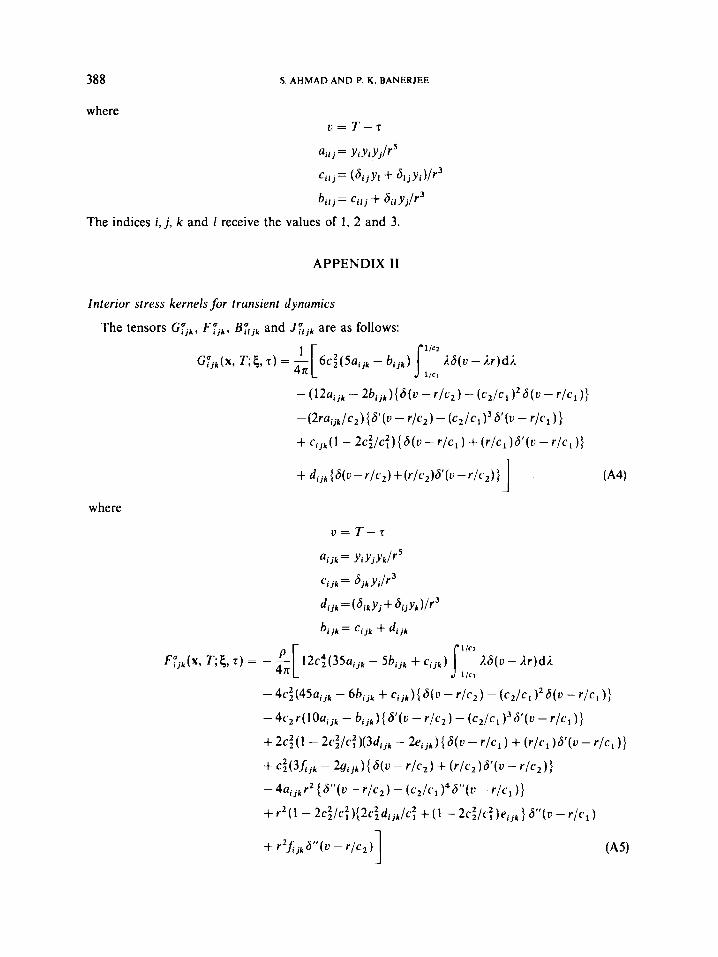
The tensors G;jk, Fyjk, B:ljk and J;ljk are as follows:
where

TRANSIENT DYNAMIC ANALYSIS BY BEM
where
389
where
For 3-01
REFERENCES
I. P. K. Banerjee and R. Butterfield, Boundary Element Methods in Engineering Science, McGraw-Hill, Maidenhead,
2. S. Mukherjee, Boundary Elements in Creep and Fracture. Elsevier Applied Science Publishers, London, 1982. U.K., 1981.

390 S. A H M A D A N D P. K . BANERJEE
3. J . Ligget and P. Liu, Boundary Integral Equationfor Porous Media Flow. Allen and Unwin, London, 1983. 4. C. A. Brebbia, J. C. Telles and L. C. Wrobel, Boundary Element Techniques-Theory and Application in Engineering,
Springer-Verlag, New York, 1984. 5. P. K. Banerjee, S. Ahmad and G. D. Manolis. 'Transient elasto-dynamic analysis of 3D problems by boundary
element method', Earthquake eng. srrucr. dyn.. 14, 933-949 (1986). 6. P. K. Banerjee and S. Ahmad. 'Advanced three-dimensional dynamic analysis of 3-D problems by boundary element,'
Proc. A S M E Conf: on Aduanced Topics in Boundary Element Analysis, Florida, AMD Vol. 72, ASME, 1985, pp. 65-81. 7. S. Ahmad, Linear and nonlinear dynamic analysis by boundary element method', Ph.D. Thesis, Department of Civil
Engineering. State University of New York at Buffalo, 1986. 8. R. B. Wilson and P. K. Banerjee. '3-D inelastic analysis methods for hot section components', Third Annual Status
Reporr (Feburary 15. 1985 ro February 15, 1986) Vol. 11. N A S A Confract Report No. 179517. 1987. 9. G. D. Manolis and D. Beskos. Private communication with a copy of Reference 7 to University of Patras, Greece,
May 1986. 10. S . Ahmad and P. K. Banerjee. 'Time domain transient elasto-dynamic analysis of 3-D solids by BEM', In?. j . numer.
merhods eny., 26, 1709-1728 (1988). I I . G. D. Manolis, S. Ahmad and P. K. Banerjee, 'Boundary element method implementation for three-dimensional
elastodynamics,' in P. K. Banerjee and J. 0. Watson (eds.), Deueloprnents it1 Boundary Element Merhods-1 V. Elsevier Applied Science Publishers. London 1985. Chapter 2, pp. 29-63.
12. P. K. Banerjee and T. G. Davies, 'Advanced implementation of boundary element methods for three-dimensional problems of elastoplasticity and viscoplasticity'. in Developments in Boundary Element Methods--3, Elsevier Applied Science Publishers, London, 1984. Chapter I , pp. 1-26.
13. P. K. Banerjee and S. T. Raveendra. 'Advanced boundary element analysis of two and three-dimensional problems of elasto-plasticity'. Inr. j. numer. rnerhods m y . , 23, 985-1002 (1986).
14. D. P. Henry, Jr., 'Advanced development of the boundary element method for elastic and inelastic thermal stress analysis', PkD. Thesis, Department of Civil Engineering, State University of New York at Buffalo, 1987.
15. Y. P. Chiu. 'On the stress field and surface deformation in a half space with a cuboidal zone in which initial strains are uniform', J. Appl. Mech. A S M E , 45, 302-306 (1978).
16. L. H. Donnell. 'Longitudinal wave transmission and impact', Trans. A S M E , 52, 153-167 (1930). 17. H. Garnet and H. Armen, 'One dimensional elastoplastic wave interaction and boundary reflections', Comp. Strucr.. 5,
18. H. Garnet and H. Armen. 'Variable time step method for determining plastic stress reflections from boundaries',
19. R. Hill, The Mathemarical Theory of Plasficify, Clarendon Press, Oxford, 1950.
327-334 (1975).
A I A A J.. 13. 532-533 (1975).