Industrial training(1)(1)
53
INDUSTRIAL TRAINING IN TCC LTD presented by JOHAN GEORGE K 12 MI01 040
-
Upload
independent -
Category
Documents
-
view
0 -
download
0
Transcript of Industrial training(1)(1)
INDUSTRIAL TRAINING IN TCC LTD
presented byJOHAN GEORGE K12 MI01 040

CONTENTS2
INTRODUCTION
PRODUCTS AND PRODUCTION PROCESS CASE STUDY

INTRODUCTION3
TCC is the first unit in India to manufacture Rayon grade Caustic Soda.
It is the heart of the industrial sector in udyogamandal sector
Only chlor-alkali process industry in Kerala
Only manufacturer of caustic soda in Kerala

HISTORY4
• FACT• MCIC
Chlor alkali unit
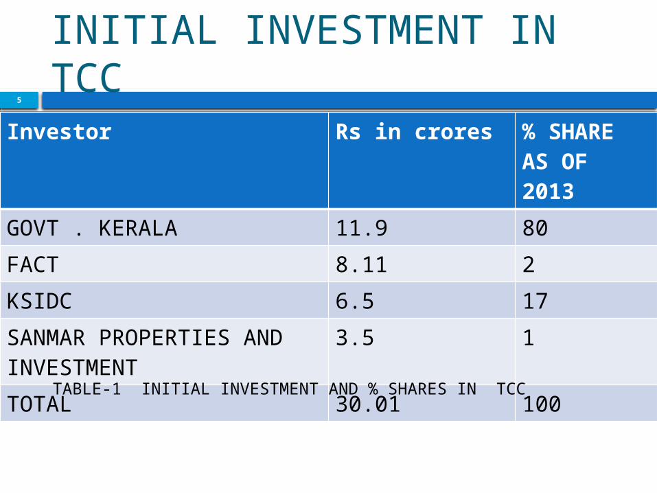
INITIAL INVESTMENT IN TCC
5
Investor Rs in crores % SHARE AS OF 2013
GOVT . KERALA 11.9 80FACT 8.11 2KSIDC 6.5 17SANMAR PROPERTIES AND INVESTMENT
3.5 1
TOTAL 30.01 100TABLE-1 INITIAL INVESTMENT AND % SHARES IN TCC

GROWTH STAGES6
YEAR GROWTH1956 A continuous Caustic Fusion Plant 20
TPD for producing Caustic Soda flakes1958 Started Chlorine Liquefaction Plant 1960 Capacity enhanced to 30 TPD further
to 40 TPD.1975 Added another 100 TPD Caustic Soda
Membrane Unit thereby increased the production capacity 200 TPD
1997 100 TPD Caustic Soda manufacturing unit using Membrane technology capacity 125 TPD.
2005 Addition 25 TPD2006 Addition 25 TPD
table 2. growth stages of TCC

MISSION AND COMPANY POLICIES7
MISSION TCC is committed to have Customer satisfaction and with its major concern for environment and Safety
QUALITY POLICY committed to enhance customer satisfaction by continually improving Quality Management System.
ENERGY POLICY TCC always committed to conservation of energy by all possible means

GOALS OR OBJECTIVES OF MANAGEMENT8
Cost effectiveness in all our operations
Regular upgrading of technologies used in processing
Compliance with laws and statutory regulations
Technological up gradation to reduce specific energy consumption
Contacting other organisations and enriching our experiences on energy conservation
Using renewable energy sources to the extend possible
Low energy fuels also to be tried depending upon feasibility

ACHIEVEMENTS9
YEAR ACHIEVEMENTS1981 Best Performance Award for Safety in the
State from Directorate of Factories & Boilers, Government of Kerala
1988-89
Best Pollution Control Award under group "Heavy Inorganic Industries" in Kerala, from Kerala State Pollution Control Board
1989 Award for Best Performance in Safety in India under "Chemical Industries" group from National Safety Council.
1989-90
Prize for Productivity from Kerala State Productivity Council.
1993 -94
Best Performance award for Energy Conservation in the State of Kerala under group "Chemical & Fertilizers – above 3000 KVA" from Government of Kerala.
Table 3. achievements of TCC
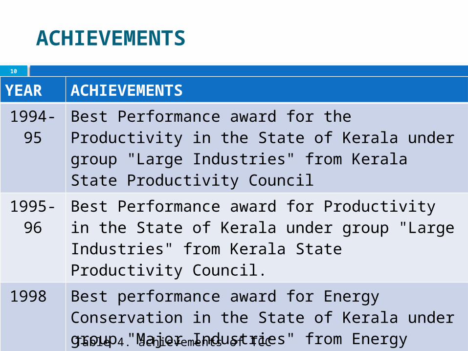
ACHIEVEMENTS10
YEAR ACHIEVEMENTS1994-95
Best Performance award for the Productivity in the State of Kerala under group "Large Industries" from Kerala State Productivity Council
1995-96
Best Performance award for Productivity in the State of Kerala under group "Large Industries" from Kerala State Productivity Council.
1998 Best performance award for Energy Conservation in the State of Kerala under group "Major Industries" from Energy Management Centre, Govt.of Kerala.
1998 Performance award for Energy Conservation under group "Chlor-alkali Sector". Ministry of Power, Government of India.
Table 4. achievements of TCC

ACHIEVEMENTS11
YEAR ACHIEVEMENTS2003 Kerala State Energy Conservation Award
(2000) in the category of Large Scale Industry
2005 National Energy Conservation Award "Chlor-alkali Sector
2012 achieved zero effluentTable 5. achievements of TCC

SALES12
ITEM SALES
YEARIN LAKHS
2012-2013 136892011-2012 124582010-2011 110642009-2010 105722008-2009 120632007-2008 93602006-2007 8869
2006-2007
2007-2008
2008-2009
2009-2010
2010-2011
2011-2012
2012-2013
8500
9500
10500
11500
12500
13500
14500
SALES IN LAKHS
SALES
Table 6. Sales data from annual reportFig 1 .sales trend of TCC
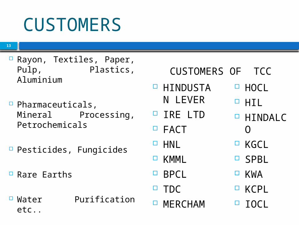
CUSTOMERS
HINDUSTAN LEVER
IRE LTD FACT HNL KMML BPCL TDC MERCHAM
HOCL HIL HINDALCO
KGCL SPBL KWA KCPL IOCL
13
Rayon, Textiles, Paper, Pulp, Plastics, Aluminium
Pharmaceuticals, Mineral Processing, Petrochemicals
Pesticides, Fungicides
Rare Earths
Water Purification etc..
CUSTOMERS OF TCC
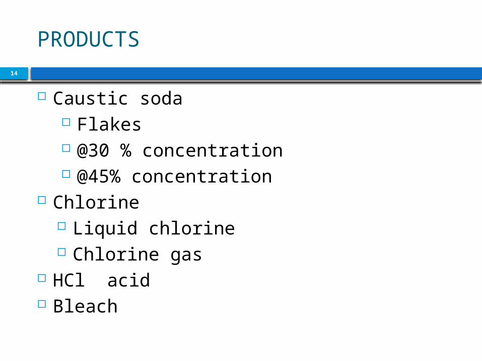
PRODUCTS14
Caustic soda Flakes @30 % concentration @45% concentration
Chlorine Liquid chlorine Chlorine gas
HCl acid Bleach
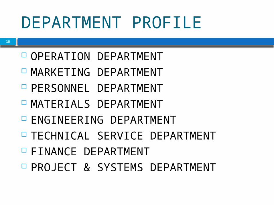
DEPARTMENT PROFILE15
OPERATION DEPARTMENT MARKETING DEPARTMENT PERSONNEL DEPARTMENT MATERIALS DEPARTMENT ENGINEERING DEPARTMENT TECHNICAL SERVICE DEPARTMENT FINANCE DEPARTMENT PROJECT & SYSTEMS DEPARTMENT

DEPARTMENT PROFILE16
department-OPERATIONS DEPT. Headed by-AGMOP

PRODUCTION PROCESS17
saturator
PPT A
PPT B
CLASSIFIER
CBT
The salt storage yard
barium carbonate
Sulphate precipitation
Sodium bisulphate
calcium
flocculants
Particles from gravity settling

PRODUCTION PROCESS18
CBT
PBFPFBT
SBF
UPBT
anthracite material packing to remove solid particles
HCL acid to increase Ph
ion exchange processIon separator for ultra
purification
HE
HT

PRODUCTION PROCESS-CAUSTIC SODA19

CHEMICAL REACTION20
ANODE CATHODE

PLANTS [CAUSTIC SODA]21
UHDE1-25MTPD
UHDE2-25MTPD
AGC-125MTPD
TOTAL-175MTPD

PRODUCTION –CAUSTIC SODA O/P22
UHDE-1, UHDE-2, AGC
MAIN STORAGE TANK [32%
MAX]
EV-1
EV-2
EV-3
MAIN STORAGE TANK [48%
MAX]PLATED DRUM
TRIPPLE EFFECT EVAPOURATOR
FLAKES STORAGE
cutting the plates we get flakes

PRODUCTION –CHLORINE O/P23
UHDE-1, UHDE-2, AGC
Chlorine gas storage
HCl plant
Drying Tower
Compressor
HE
Liquid chlorine
storage tank Freon gas @-11°C

PRODUCTION-HCL ACID24
Water is sprayed to dissolve the fumed HCl gas to acid
Oven for HCl production
There is an igniters for burning the hydrogen and chlorine gasAbsorpti
on tower
HCl Storage Tank

PRODUCTION –SODIUM HYPO CHLORITE25
Chlorine gas storage
Waste chlorine from seal overflow or leakage
32 % NaOH lye
Chlorine is passed
through NaOH solution
Sodium hypochlorite
Cl2 + 2 NaOH → NaCl + NaClO + H2O

SWOT ANALYSIS26
OPPORTUNITY New project is mainly for helping isro for making solid propellant

SWOT ANALYSIS27
STRENGTH Only chlor alkali unit in state Financed by government Building block of many other industry
Low human intervention in process Raising demand of product Accidents are very least in TCC Raising demand of product

SWOT ANALYSIS28
WEAKNESS Lack of manpower Lack of profit motive Unrevised price policy

SWOT ANALYSIS29
OPPORTUNITY New project is mainly for helping isro for making solid propellant
Increasing the hydrogen utilization from the present level of 76% to 95% by installing an additional Hydrogen Blower.

SWOT ANALYSIS30
THREAT High price of electricity Competitor from abroad Infrastructure is obselete

FUNCTIONS31
Maximizing production confirming to specification
Optimizing consumption of electricity
Minimize overheads
Fixes the monthly target
Modification of production process
Act as emergency controller
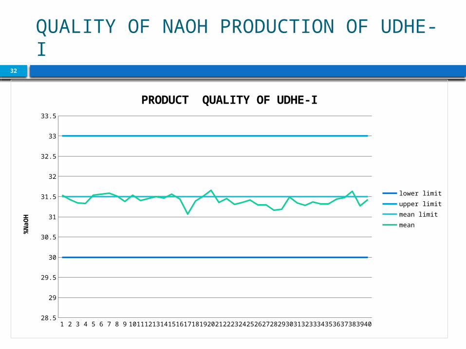
QUALITY OF NAOH PRODUCTION OF UDHE-I
32
1 2 3 4 5 6 7 8 9 1011121314151617181920212223242526272829303132333435363738394028.5
29
29.5
30
30.5
31
31.5
32
32.5
33
33.5
PRODUCT QUALITY OF UDHE-I
lower limitupper limitmean limitmean
%NaO
H

QUALITY OF NAOH PRODUCTION OF UDHE-II
33
1 2 3 4 5 6 7 8 9 1011121314151617181920212223242526272829303132333435363738394028.5
29
29.5
30
30.5
31
31.5
32
32.5
33
33.5
PRODUCT QUALITY OF UDHE II
MLLLUL% NaOH IN UDHE 2
% Na
OH -
UDHE
II

QUALITY OF NAOH PRODUCTION OF AGC34
1 2 3 4 5 6 7 8 9 1011121314151617181920212223242526272829303132333435363738394028.5
29
29.5
30
30.5
31
31.5
32
32.5
33
33.5
PRODUCT QUALITY-AGC
LLULMLMEAN % NaOH
% Na
OH -
AGC
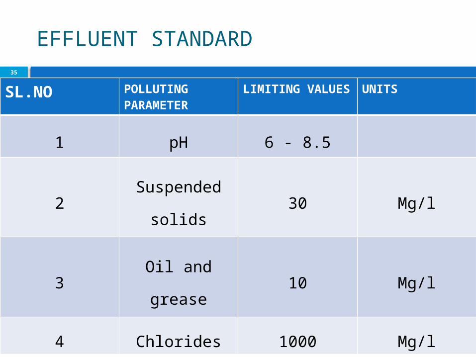
EFFLUENT STANDARD35
SL.NO POLLUTING PARAMETER
LIMITING VALUES UNITS
1 pH 6 - 8.5
2Suspended
solids30 Mg/l
3Oil and
grease10 Mg/l
4 Chlorides 1000 Mg/l

EMISSION STANDARDS36
SL.N
OEMISSION SOURCE PARAMETER
LIMIT(mg/
mm3)
1 HCL UNIT1.CL 15
2.HCL 35
2 SALT HEATER1.SO2 1200
2.NOX 450
3 BOILER
particulate
matter150
2.SO2 200
4SODIUM
HYPOCHLORITE1.CL 15

Zero effluent37
No discharge to the river in any form
This is achieved either by recycling from the source into appropriate process step
utilizing for useful purposes such as horticulture after required treatment or rectification.
Reduce , reuse and recycle is the basic principle adopted for attainment of the zero discharge status

The effluent treatment system
38
consist of the following1. High density polyethylene pipes for the
collection and routing acidic/alkaline effluent
2. Acidic alkali proof brick lined tanks, collection pit and reaction pit
3. Buffer storage for treatment4. Acid or alkali proof brick lined pits for
acidic and alkaline water collection in brine purification
5. Acid and alkaline effluent can be used for maintaining pH and they combine to form ultrapurified brine
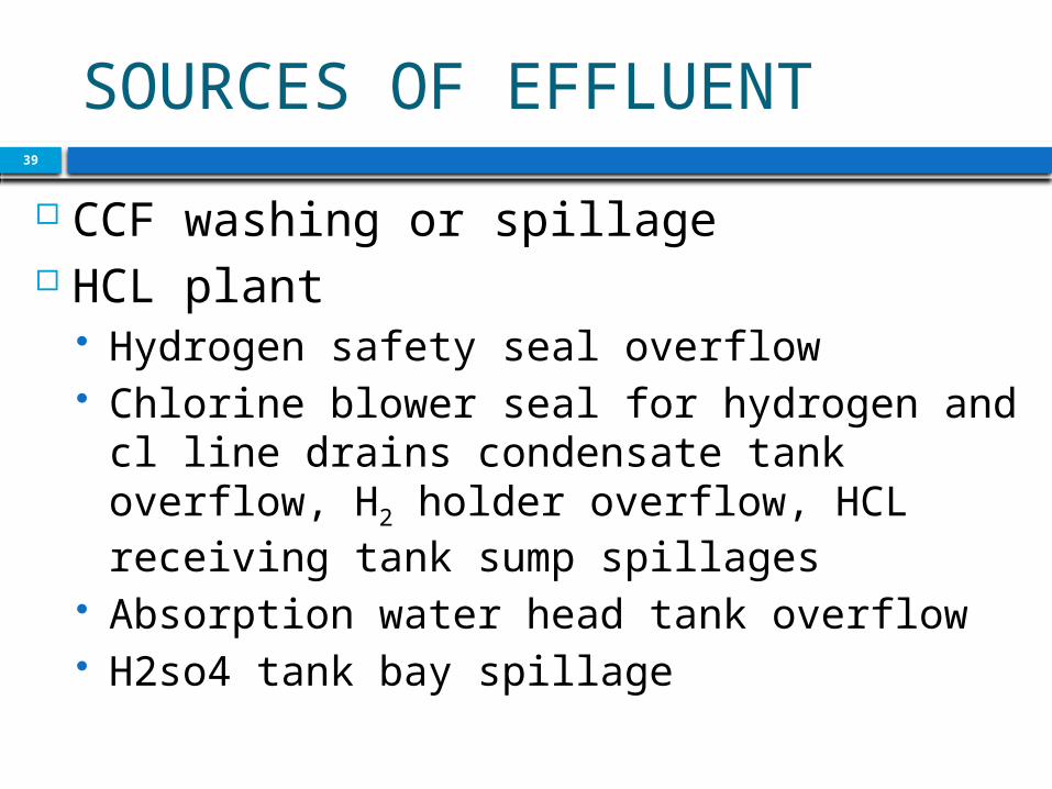
SOURCES OF EFFLUENT39
CCF washing or spillage HCL plant
Hydrogen safety seal overflow Chlorine blower seal for hydrogen and cl line drains condensate tank overflow, H2 holder overflow, HCL receiving tank sump spillages
Absorption water head tank overflow H2so4 tank bay spillage

SOURCES OF EFFLUENT40
Chlorine liquefaction H2SO4 spillage
AGC plant Receiving tank bay spillage from cell house
Condensate from separator after H2 cooler
Bisulphate from seal leaks Caustic spillage from product cooling area

SOURCES OF EFFLUENT41
Dm water unit Acidic/Alkaline effluent from regeneration steps of cationic or anionic and mixed bed resin tower
Secondary brine purification plant
Acidic or alkaline effluent from regeneration steps
Chlorine cylinder filling station
Cylinder washing effluent

SOURCES OF EFFLUENT42
Sodium hypochlorite plant Chlorine line seal overflow Effluent from lab spillages
UHDE I & I Alkaline condensate from hydrogen lines
Sources of oil spillage Main furnace oil storage tank area Furnace oil day tank area in CCF and boiler houses
Oil spillages from boiler house

ALKALINE EFFLUENT43
HDPE pipes are laid to collect and bring alkaline water from the secondary resin towers and DM water units to a collection pit having the capacity of 25m3.
The main sources are CCF, regeneration steps and resin towers for DM water and secondary brine purification system
Treatment Sodium hypochlorite productionCylinder washingAcidic effluent neutralization

ACIDIC EFFLUENT44
HDPE pipe are laid to collect and bring the acidic water to the collection pit identified for acidic water.
The source are regenerated steps in DM water units and secondary brine purification system
MSRL tank is provided as a buffer tank for storing acidic effluent.
The acidic or alkaline effluent can be used to regulate the pH of the effluent
pH of the ultra purified brine to the electrolysis.
Acid effluent from HCL plant and alkaline effluent from CCF can be used to produced the raw material ie purified brine

EFFLUENT TREATMENT45
The mixed effluent is led to the effluent collection pit directly.
Acidic and alkaline water from various sources collected in buffer storage tank are used for treatment and neutralization as per the requirement.
There is an online pH measuring instrument that will monitor the pH of the water and make the treatment accordingly
NaHSO3 is added to kill any chlorine present. pH is monitored continuously. After neutralization it is pumped out to drain lending to delay pond . from the delay pond, water is being pumped for horticulture.

AIR POLLUTION46
The major sources of air pollution are Stack emission from molten salt heater in ccf plant
Stack emission from boiler house Vent to HCL synthesis unit

EMISSION CONTROL47
STACK EMISSION FROM MOLTEN SALT HEATER AND BOILER Here furnace oil is used as the fuel. For ensuring proper combustion the burner is equipped with air fuel ratio controller.
A significant quantity of hydrogen from UDHE 1&II and AGC is utilized here as a fuel thus reducing furnace oil consumption
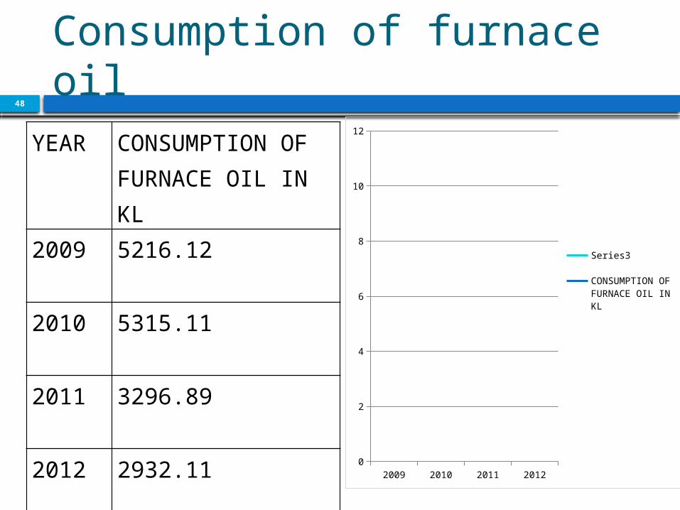
Consumption of furnace oil
48
YEAR CONSUMPTION OF FURNACE OIL IN KL
2009 5216.12
2010 5315.11
2011 3296.89
2012 2932.11 2009 2010 2011 20120
2
4
6
8
10
12
Series3
CONSUMPTION OF FURNACE OIL IN KL

EMISSION CONTROL49
EMISSION CONTROL IN VENT EMISSION hydrogen is always kept in 10% excess than the stoichiometric requirement
For immediate corrective action a bubbler system, where stack gases are drawn continuously trough bubbler having methyl orange indicator
The HCL concentration is checked frequently and maintained in the range 30 to 32% for complete absorption of HCL gas.
A tail gas absorber is mounted over the unit and fresh water is fed to this unit to absorb residual gases from HCL synthesis unit below.
This ensures that HCL gas is almost nil in stacks

Added advantage50
Ensure 100% utilization of raw material Maintenance cost will be reduced by 29% Frequency of plugging of pipe lines due to scale formation is less
Tax benefit is also there as company is having high quality environmental management
The chemical ingredient requirement for the process also decreased

FINDINGS51
Depends heavily on electricity Accidents are very least in TCC, Pricing policy is unrevised No strikes reveals workers management healthy relation
TCC has high regard from customers in matter of quality of product and timely delivery

SUGGESTION 52
Find the opportunity of producing more products
Improving combustion efficiency of furnace oil by using fuel additions
Use of roof transparent sheets wherever possible, to avoid electric lighting during day time.
Persuade to use more safety equipments
Necessary steps to increase net profit
Revise the pricing policy

53