Training-Manual.pdf - 1 File Download
376
-
Upload
khangminh22 -
Category
Documents
-
view
3 -
download
0
Transcript of Training-Manual.pdf - 1 File Download


AceCad StruCad AceCad
Training Manual for StruCad i
The World’s Leading 3-D Structural Steel Detailing System
Copyright © 1986 to 2008 AceCad Software Ltd
All Rights Reserved Users and distributors of StruCad are reminded that no part of this training publication may be reproduced or transmitted in any form or by any means, whether it be electronic, mechanical, photocopying, recording or otherwise, except for their specific use related to the authorised and licensed training in the use of StruCad® and its related products.
AceCad Software Ltd makes no warranty regarding these materials; either expressed or implied (including any implied warranties of merchandising or fitness for a particular purpose), and makes such materials available solely on an “as-is” basis.
AceCad reserves the right to revise and improve its products as it sees fit. This publication describes the state of the version of the StruCad product to which it refers, at the time of publication on the front cover, and it may not reflect the product at all times in the future.
For conditions of use, and for permission to use these materials for translation and publication in languages other than English, contact AceCad Software Ltd.
Editor’s Note This StruCad Training Manual is published to support StruCad and is designed to teach you the basics of how to use StruCad. The manual forms the basis of the formal StruCad training courses that are given by StruCad staff at your local StruCad Training Centre, or on your own site. It is recommended most strongly that you have formal training wherever possible, to ensure that you get the best out of StruCad, and benefit fully from the timesavings that come with its proper use.
These notes are supported by user information that is available in the StruCad Reference Manuals and in StruCad’s On-line Help, which should be studied in the early stages of training. To view the books on-line, use WordViewer with the books from the \manuals directory that can be installed from the StruCad CD, or by browsing on the CD itself. Special users guides are available for particular features of StruCad, such as 2D Drafting or Stairs and Handrails macros. If you do not have a copy of a particular document, its Word document file will be found in the \Manuals directory on your CD.
Associated Manuals and Guides 1. StruCad Reference Manual for the 3D Modelling Environment. 2. Drawing Reference Manual for the 2D Drawing Environment. 3. StruCad Setup and Installation Guide. 4. StruCad Advanced Training Course and associated documents. AceCad and StruCad are registered Trade Marks of the RDS Group. AceCad’s policy is one of continual improvement and product specifications may be subject to change without notice.
RV15-1 - -082 16

This StruCube will help you identify the Local Axes and Rotations of
members of various sections – UB, RSC, TEE, RHS & RSA.
End B
X
Y
End A
X
Y
+ +
Acecad Software Ltd
Truro House
Stephenson’s Way
Wyvern Business Park
Derby DE21 6LY
Tel: 01332 545800 Fax: 01332 545801
E-mail: [email protected]
Website: www.acecad.co.uk
Assemble the StruCube. ®

Exercise 1 StruCad Basic CAD Principles
Training Manual for StruCad
The World’s Leading 3-D Structural Steel Detailing System
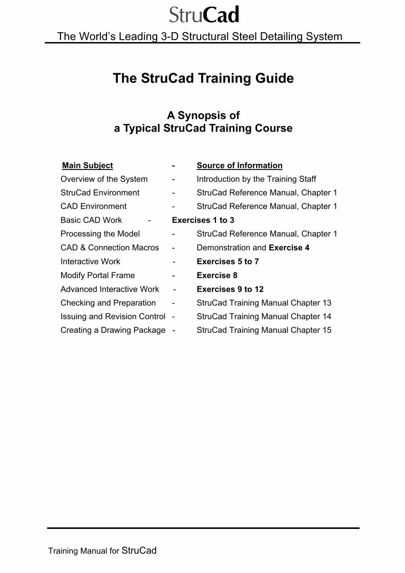
The StruCad Training Guide
A Synopsis of a Typical StruCad Training Course
Main Subject - Source of Information Overview of the System - Introduction by the Training Staff StruCad Environment - StruCad Reference Manual, Chapter 1 CAD Environment - StruCad Reference Manual, Chapter 1
Basic CAD Work - Exercises 1 to 3 Processing the Model - StruCad Reference Manual, Chapter 1
CAD & Connection Macros - Demonstration and Exercise 4 Interactive Work - Exercises 5 to 7 Modify Portal Frame - Exercise 8 Advanced Interactive Work - Exercises 9 to 12 Checking and Preparation - StruCad Training Manual Chapter 13 Issuing and Revision Control - StruCad Training Manual Chapter 14 Creating a Drawing Package - StruCad Training Manual Chapter 15


Contents StruCad Contents
Training Manual for StruCad
The World’s Leading 3-D Structural Steel Detailing System
The StruCad Training Guide CONTENTS Overview Introducing a Typical Training Course ii-vi Summary and Checklist of the Basic StruCad Activities vii-xii
STRUCAD TRAINING COURSE WORKING EXERCISES
Exercise 1 ............................... Basic Cad Principles
Exercise 2 ............................... Beam and Column Structure
Exercise 3 ............................... Portal Frame Structure
Exercise 4 ............................... Macro Connections - Principles and Examples
Exercise 5 ............................... Interactively Reposition CHS Eaves Tie
Exercise 6 ............................... Interactive Base Plate
Exercise 7 .............................. Connection to Toes of Supporting Beam
Exercise 8 ............................... Portal Frame Including Lattice and Hips
Exercise 9 ............................... Interactive Double Angle Cleat
Exercise 10 ............................... Interactive Sloping Connections
Exercise 11 ............................... Interactive Haunch Connection -
Utilising Dummy Members
Exercise 12 ............................... Interactive Eaves Bracket Connection
Issue Procedure .........................Checking, Issuing and creating Packages
i

Notes StruCad Notes
ii
The World’s Leading 3-D Structural Steel Detailing System
STRUCAD TRAINING COURSE
Overview
Introduction In general, StruCad training can take any number of forms, and this Training Manual will guide you during your particular training process.
Many of the procedures and activities will be demonstrated to you as your training proceeds, but all the basic user information on how to use StruCad and its CAD environment is also explained in the StruCad Reference Manual, Chapter 1 and in the On-line HELP.
The Training Course consists of a number of worked exercises, which teach you how to use StruCad to carry out all the detailing activities that you need complete a normal contract.
The Training Course will teach you the basics of StruCad, and by the end of the course you will know enough about StruCad to input almost any type of structure. You may not think so, but it is just a case of applying the principles and techniques that you have learned to different situations. It is extremely important that you inform the Trainer if you do not understand anything whilst on the course, so that you can go over the activity or exercise again until you do understand it. Finally, do not be scared of StruCad - it is a program, which, if used correctly as a tool in your office, will provide great benefits to your company.
If there is time at the end of your course, you may be introduced to some of StruCad’s more advanced features. Otherwise, special extra training can be arranged for this.
You cannot break the program; at the very worst you will input something wrong which can easily be re-done or corrected - so be adventurous, try things and, if you have spare time, look at commands that are new and explore the programme. You will learn more about the StruCad System by experimenting for yourselves and, as you will soon realise, you will learn more about StruCad in the first few weeks

Exercise 1 StruCad Basic CAD Principles
Training Manual for StruCad 1-1
1
The World’s Leading 3-D Structural Steel Detailing System
Exercise 1
BASIC CAD PRINCIPLES
The objectives of this exercise are to use and understand the StruCad menu system, the major commands required to build a simple model, and the basic concepts of 3D modelling.
SEQUENCE
Starting StruCad and Creating a Structure
(1) Create Grid Lines
(2) Create Levels
(3) Add Top Level Lines
(4) Add Bottom Level Lines
(5) Add Vertical Lines
(6) Add Triangular lines
(7) Add Lines Between Sloping Lines
(8) Manipulate your On-screen View

Exercise 1 StruCad Basic CAD Principles
1-2 Training Manual for StruCad
The World’s Leading 3-D Structural Steel Detailing System
StruCad V15.lnk
Exercise 1
BASIC CAD PRINCIPLES
HINT
You can type “U” for UNDO immediately after you have done something that you would like to do again (either because it is wrong, or because you would like to try it again). If it was a reversible action, StruCad will undo it after you have OK’d the confirmation box. Irreversible activities (e.g. modelling) are ignored by UNDO. If you select a command by mistake you can cancel this command at any time by pressing the ESC key on the keyboard.
PROCEDURE
Starting StruCad
On the desktop double click on the StruCad Icon:
Or alternatively use the Start menu from the prompt bar and select the StruCad option from the Programs toolbar:
The StruCad splash screen will appear with a welcome message. This will quickly disappear, to be followed by the StruCad Software Licence Agreement screen, which is displayed for confirmation. After you press Accept, the StruCad Workspace will appear.

Exercise 1 StruCad Basic CAD Principles
Training Manual for StruCad 1-3
1
The World’s Leading 3-D Structural Steel Detailing System
At the StruCad Workspace, click onto the New button - this will create the framework for a new StruCad model. A dialog box for the new model will now appear, as below.
Define the correct Language Dataset for use with this model. For this exercise we will use the ‘UK’ option. Fill in the Model Name, Contract Name, Description and your own details as shown and click on the OK button. Note that this information will appear on the final material lists, fabrication drawings, etc, so it must be correct (although it can be edited at a later date). The StruCad 3-D Modelling Environment will then start - it is within this environment that we will create the 3-D simulation of the structure.
The main On-line Help is started by pressing the Help button at the Workspace Minimise it ready for re-use when you have finished referring to it.
NOTE: You can also start the On-line Help when in the modelling environments, by clicking a command button (for details see later).

Exercise 1 StruCad Basic CAD Principles
1-4 Training Manual for StruCad
The World’s Leading 3-D Structural Steel Detailing System
The StruCad 3-D Modelling Environment
Command Access and Locations
1) The Icon Tool Bar Menu System Framing the StruCad model workspace, to both sides and the top, there are a series of default toolbars. These toolbars will access most of the commands within the StruCad 3D modelling environment. Additional toolbars may be added, as required, by selecting the ‘toolbars’ command from the bottom of the left-hand screen menu. The composition and locations of these toolbars may be varied, or completely new ones may be created to suit personal preferences. 2
The Icon Toolbar Menu System
2) The Pull-down Menu System If you move the cursor to the ‘written’ toolbar at the top of the screen and depress the left-hand mouse button, a pull-down menu system will appear as shown - the most common commands are found here. Select the required command by placing the cursor over the command, (it will highlight blue) and then pressing the left-hand mouse button, (alternatively, keep the left mouse button depressed and release over desired command). Some of these pull-down menus are tiered, as indicated by a small arrow to the right of a command. These tiers will contain commands, which are relevant to, or an extension of the parent command.

Exercise 1 StruCad Basic CAD Principles
Training Manual for StruCad 1-5
1
The World’s Leading 3-D Structural Steel Detailing System
The Pull-down Menu System
3) The Floating Menu System Another menu system can be accessed by moving the mouse cursor into free space within the StruCad modelling environment, and then pressing the third (right-hand) button on the mouse. This menu system is referred to as the floating menu system, and it gives you rapid access to all the main commands used for a particular activity. The working area of the screen is split into logical areas for the purpose of generating these right-click floating menus:
Right clicking in each of these areas brings forward a different floating menu system. For example, if you click in the top left-hand area you will get the menu of commands, as shown left, to be used for Creation activities:
The Icon Toolbar floating menu To get help on a command in an Icon Toolbar floating menu, depress the ‘Shift’ key and left click the command button.

Exercise 1 StruCad Basic CAD Principles
1-6 Training Manual for StruCad
The World’s Leading 3-D Structural Steel Detailing System
4) Typing Commands All StruCad commands are also typeable in the Command Line. Any command, such as MEMBER, can be executed by simply typing in “member” when the Command Line says “Ready”. Most commands have typeable shortcuts, such as MEM for the member command – these shortcuts are highlighted in upper case letters on most menus.
Creating a Structure within StruCad
When creating a structure within StruCad, there are two major building blocks that may be used. The first of these building blocks is the grid, which consists of a matrix of intersecting centre lines or grid lines on which the building is constructed.
Most grids will fall into one or other of two main categories; -
The first category would be a Regular Grid, in which all bay sizes would be equal in either direction. For this type of grid we would use the command GLayout. The second category would be an Irregular Grid, in which bay sizes may vary in size in either, or both, directions. For this type of grid we would use the command SLAyout.
(1) Create Grid Lines sk 1.1 SLAyout - (Select from the Icon Toolbar menu system) Choose the SLAyout command since it allows the user to input an irregular matrix of grid lines.
Use Default Settings, ie: Attributes Table: Separation in X = 5000,5000 Separation in Y = 6000 Accept this layout, and then press Enter (or click the middle mouse button) to fix the location of grid lines. Confirm that the layout displayed as in sk 1.1 is OK by accepting yes in the yes/no dialog box when it appears:

Exercise 1 StruCad Basic CAD Principles
Training Manual for StruCad 1-7
1
The World’s Leading 3-D Structural Steel Detailing System
(2) Create Levels The second building block for a StruCad structure is to input the datum levels of the structure.
LEVEl - (Select from the Icon Toolbar menu system) The Level command allows the user to input into the StruCad model the basic structural levels required.
Select ‘New’

Exercise 1 StruCad Basic CAD Principles
1-8 Training Manual for StruCad
The World’s Leading 3-D Structural Steel Detailing System
Create two levels: BOT 0.0 Red TOP 6000 Magenta
Each level must be entered independently:
(3) Add Top Level Lines sk 1.2 • Change Working Level to Top
SETLEv - (Select from the Icon Toolbar menu system)
The SETLEv command allows the user to move the grid lines up and down between any defined levels.

Exercise 1 StruCad Basic CAD Principles
Training Manual for StruCad 1-9
1
The World’s Leading 3-D Structural Steel Detailing System
Choose TOP level (This moves the grid to the top level we have just created and also sets the current layer to TOP.) Note: Layers and levels are independent of each other.
• Add Lines
The LINE command allows the user to introduce construction lines into the StruCad model. These lines are used for setting out points etc, and are invisible to the structure itself - they will not be shown on fabrication drawings or material lists etc. LINE - (Select from the Icon Toolbar menu system)
When inputting any entity within StruCad, a start point and end point must be defined. One way to define these points is to use SNAP points, (for further explanation see the main Reference Manual, Chapter 1). A ‘Snap Modes’ menu of snaps is available when a command, such as LINE, is being executed and then the right button on the mouse is pressed. So, in this case, the order of commands is as follows: Select LINE command from the Icon Toolbar, you will then be asked for a start point. Press right button on the mouse to get Snap Modes box. With left button, select snap mode Intersection, then select the start intersection point in the model (again with left mouse button). You will then be asked for an end point.
Again press the right (or third) button on the mouse to open Snap Modes, and (with left mouse button) select snap mode ‘Intersection’, then select the end intersection point in the model.

Exercise 1 StruCad Basic CAD Principles
1-10 Training Manual for StruCad
The World’s Leading 3-D Structural Steel Detailing System
Using this method draw lines in the model as follows: Start Point ........ INT (Intersection of Grid line 1 and Grid line A) To Point ......... INT (Intersection of Grid line 1 and Grid line B) To Point ......... INT (Intersection of Grid line 2 and Grid line B) To Point ......... INT (Intersection of Grid line 2 and Grid line A) To Point ......... INT (Intersection of Grid line 1 and Grid line A) This will draw a rectangle over the grid lines at the top level of the building as shown in sk1.2.
To end the LINE command, press the Esc key on your keyboard, or press the middle (accept/exit) mouse button.
Exercise 1 StruCad Basic CAD Principles
Training Manual for StruCad 1-11
1
The World’s Leading 3-D Structural Steel Detailing System
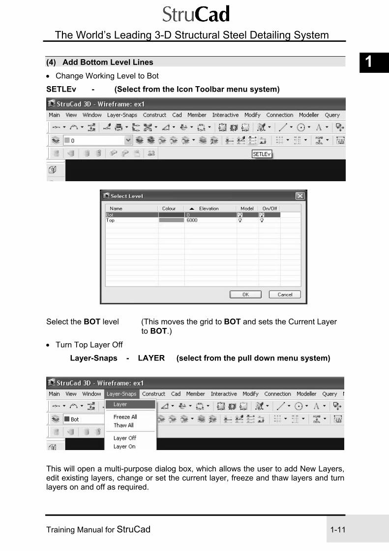
(4) Add Bottom Level Lines • Change Working Level to Bot
SETLEv - (Select from the Icon Toolbar menu system)
Select the BOT level (This moves the grid to BOT and sets the Current Layer to BOT.)
• Turn Top Layer Off
Layer-Snaps - LAYER (select from the pull down menu system)
This will open a multi-purpose dialog box, which allows the user to add New Layers, edit existing layers, change or set the current layer, freeze and thaw layers and turn layers on and off as required.

Exercise 1 StruCad Basic CAD Principles
1-12 Training Manual for StruCad
The World’s Leading 3-D Structural Steel Detailing System
TOP - Double click left mouse button to switch off ‘Light Bulb’ and layer, or, right mouse button to open the options table shown, and select ‘Off’
Add Lines
LINE - (Select from the Icon Toolbar menu system)
Start Point ........ INT (Intersection of Grid line 1 and Grid line A) To Point ......... INT (Intersection of Grid line 1 and Grid line B) To Point ......... INT (Intersection of Grid line 2 and Grid line B) To Point ......... INT (Intersection of Grid line 2 and Grid line A) To Point ......... INT (Intersection of Grid line 1 and Grid line A)
This will draw a rectangle over the grid lines at the bottom level of the building as shown in sk1.2.
Press the Esc key on your keyboard to end the line command.

Exercise 1 StruCad Basic CAD Principles
Training Manual for StruCad 1-13
1
The World’s Leading 3-D Structural Steel Detailing System
(5) Add Vertical Lines • Create a New Working Layer
Layer-Snaps - LAYER (select from the pull down menu system)
Select ‘New’ - Name = Verts Colour = Yellow
• Display Other Layers
Layer-Snaps - All On (select from the pull down menu system)
Accept

Exercise 1 StruCad Basic CAD Principles
1-14 Training Manual for StruCad
The World’s Leading 3-D Structural Steel Detailing System
• Change Working View to View Wireframe Model from another Direction.
View - View - ISO Above (4 o’clock position) (select from the pull-down menu system)
• Add Vertical Lines
LINE - (Select from the Icon Toolbar menu system)
See Sketch. sk 1.3

Exercise 1 StruCad Basic CAD Principles
Training Manual for StruCad 1-15
1
The World’s Leading 3-D Structural Steel Detailing System
Line-1 Start Point ........ INT (Intersection of Grid line 1 and Grid line A @ BOT level) To Point ......... INT (Intersection of Grid line 1 and Grid line A @ TOP level) Press Enter twice (once to finish line, and again to re-select the LINE command)
Line-2 Start Point ........ INT (Intersection of Grid line 1 and Grid line B @ BOT level) To Point ......... INT (Intersection of Grid line 1 and Grid line B @ TOP level)
Press Enter twice
Line-3 Start Point ........ INT (Intersection of Grid line 2 and Grid line A @ BOT level) To Point ......... INT (Intersection of Grid line 2 and Grid line A @ TOP level)
Press Enter twice
Line-4 Start Point ........ INT (Intersection of Grid line 2 and Grid line B @ BOT level) To Point ......... INT (Intersection of Grid line 2 and Grid line B @ TOP level) Press Esc to finish.
(6) Add Triangular Lines sk 1.4 • Create a New Layer
LAYER - (select from the Icon Toolbar menu system)
Select ‘New’ Name = Triangle Colour = Magenta

Exercise 1 StruCad Basic CAD Principles
1-16 Training Manual for StruCad
The World’s Leading 3-D Structural Steel Detailing System
• Add Lines
LINE - (Select from the Icon Toolbar menu system)
Again, use Snap Modes (right mouse button) to pick points, described below, shown in sketch sk 1.4 Start Point ........ INT (Intersection of Grid line2 and Grid line A at BOT level) To Point ......... MID (Midpoint of line at TOP level) Use middle mouse button to make the line ‘string’ (i.e. start the next line where the previous one finished.) Finish Point ….. INT (Intersection of Grid line 2 and Grid line B at BOT level)

Exercise 1 StruCad Basic CAD Principles
Training Manual for StruCad 1-17
1
The World’s Leading 3-D Structural Steel Detailing System
• Copy Lines
COPY - (Select from the Icon Toolbar menu system)
Select Entities .... Select both sloping lines then press Enter or use middle mouse button to confirm selection.
Base Point ........ INT (Intersection of Grid line 2 and Grid line A @ BOT level)
New Point ..….....INT (Intersection of Grid line 3 and Grid line A @ BOT level)

Exercise 1 StruCad Basic CAD Principles
1-18 Training Manual for StruCad
The World’s Leading 3-D Structural Steel Detailing System
(7) Add Lines between Sloping Lines z
Top Line sk 1.5 • Set UDS to Plane of Slope
UDS - 3 Points (Select from the Icon Toolbar menu system)
Select 3 Points shown in sk 1.5 ... INT , INT , INT
This aligns the vectors of the UDS with the sloping plane of the model, and allows easy positioning of lines between the two sloping lines.
By aligning the UDS (User Defined Space) to the slope of the triangle,
it allows us to easily position lines along that slope.

Exercise 1 StruCad Basic CAD Principles
Training Manual for StruCad 1-19
1
The World’s Leading 3-D Structural Steel Detailing System
• Add Line
LINE - (Select from the Icon Toolbar menu system) Use Right mouse button to access ‘Snap Modes’ Start Point ...... REF, INT/END, (INT/END means INT or END) - Select Intersection at 3 . .
End Point …….. PERP (Perpendicular) to sloping line on grid line 3 - see sk 1.5 .
A Reference Point allows you to position your required point relative to the point you choose (see Reference Manual, Chapter 1).
Lower Line sk 1.6
Y = -1000

Exercise 1 StruCad Basic CAD Principles
1-20 Training Manual for StruCad
The World’s Leading 3-D Structural Steel Detailing System
• Set UDS back to WORLD
UDS - World (Select from the Icon Toolbar menu system)
• Add Line
LINE - (Select from the Icon Toolbar menu system)
Select - LINE - Along
The ‘Along’ SNAP is another way of positioning lines along a slope without changing the UDS.
Start Point - Select Line ‘X’ (the line to reference along)
Ref point INT/END point (the point to Reference from)
Direction INT/END point (the Direction along the line)
Distance - 1000 (Type in from keyboard)
End Point – Select Perpendicular from Snap Modes Select sloping line on grid line 3

Exercise 1 StruCad Basic CAD Principles
Training Manual for StruCad 1-21
1
The World’s Leading 3-D Structural Steel Detailing System
`
(8) Manipulate your On-screen View
Use Zoom In, Zoom Out, PZI or PZO (see Note below), Window in, Pan, Fit, Previous, Layers, Views and Ports until you fully understand them, since you will be using them all the time.
(You can select them from the Icon Toolbar, a floating menu ( top right ) or from the pull down menu system.)
WI ZI
ZO FIT
PREV
PAN

Exercise 1 StruCad Basic CAD Principles
1-22 Training Manual for StruCad
The World’s Leading 3-D Structural Steel Detailing System
NOTE on Zoom Commands There is a slight difference between the ZO command and the PZO command, and also between ZI and PZI. ZO and ZI operate just once and then exit, whereas PZO and PZI are perpetual, and allow the middle button to execute the opposite action. In general, you are best using PZO, where the left button zooms out and the middle button zooms in. Press Esc to finish.
Main Exit Save
NOTES

Exercise 2 StruCad Beams and Columns
Training Manual for StruCad 2-1
2
The World’s Leading 3-D Structural Steel Detailing System
Exercise 2
BEAM AND COLUMN STRUCTURE (New model)
Exercise 2 takes the commands that you have learnt in Exercise 1 and applies them to the construction of a solid structure of beams and columns.
SEQUENCE
Create a New Model
(1) Create Grid Lines
(2) Create Levels and Layers
(3) Add Primary Members to First Floor
(4) Add Secondary Members
(5) Add More Secondary Members

Exercise 2 StruCad Beams and Columns
2-2 Training Manual for StruCad
The World’s Leading 3-D Structural Steel Detailing System
(6) Copy Primary Members to Second Floor
(7) Add Columns from USBP up to 2nd Floor
(8) Add Columns from USBP up to 1st Floor
(9) Add Offsets to Primary Members
(10) Create Construction Lines
(11) Automatically Add Offsets
(12) Add Top of Steel Flag to Sloping Members
(13) Add Side of Steel Flag
(14) Update the Model
(15) Working in Wire or Solid Format
(16) Produce Material Lists

Exercise 2 StruCad Beams and Columns
Training Manual for StruCad 2-3
2
The World’s Leading 3-D Structural Steel Detailing System
Exercise 2 BEAM AND COLUMN STRUCTURE
PROCEDURE
Create a New Model

Exercise 2 StruCad Beams and Columns
2-4 Training Manual for StruCad
The World’s Leading 3-D Structural Steel Detailing System
(1) Create Grid Lines sk 2.1 SLAyout - (Select from the Icon Toolbar menu system)
• Create 7 “numeric” lines (with separations in x direction) and 5 “alpha” lines.
Change settings to: Separation in X = 6000,6000,6000,6000,6000,6000 Separation in Y = 6100,6100,6100,6100
Use default grid line name labels. ACCEPT this layout.
When asked for location of Grid Origin in the Command Line, press Enter to accept default 0,0,0. The grid lines should then be displayed as shown in the layout below. If layout is OK, confirm by accepting the YES/NO dialog box.
The Basic Grid Created by SLAYOUT

Exercise 2 StruCad Beams and Columns
Training Manual for StruCad 2-5
2
The World’s Leading 3-D Structural Steel Detailing System
• Remove Grids 6,7 Erase - (Select from the Icon Toolbar menu system)
Select Grid Lines 6,7 to be erased:
The Grid Layout after Erasing Grid Lines 6 and 7
• Add New Grid Line 6
Sgrid - (Select from the Icon Toolbar menu system) This command will add a single grid line.
Enter grid line name (Enter number 6) Start Point of grid line ........ REF, INT (Intersection of Grid lines A and 5, X = 5000) End Point of grid line ......... REF, INT (Intersection of Grid lines B and 5, X = 7500)
Note - To find ‘Reference’ and ‘Intersection’ (REF, INT) above, use right mouse button to access ‘Snap Modes’ each time you need either REF or INT.

Exercise 2 StruCad Beams and Columns
2-6 Training Manual for StruCad
The World’s Leading 3-D Structural Steel Detailing System
The Grid Layout after Adding Grid Line 6
• Add New Grid Line 7
Trim - OFFSet - Distance - (Select from the Icon Toolbar menu system Using the ‘down arrow’ to the right of Trim)
The OFFSet command will copy an entity by a specified distance from its current position. Enter offset Distance = 5000 Select the Grid line to Offset (Line 6)
Direction (Select right hand side of Grid Line 6) (Middle button to cancel command)
• Rename the new grid line that was offset, using the EDGrid command. Move the cursor so it is over the new Grid Line 6 then press the right-hand button on the mouse. A choice of commands will appear (these menus are known as “object driven menus”.) This menu has commands appropriate only to grid lines, and will apply the one you choose to the line selected.

Exercise 2 StruCad Beams and Columns
Training Manual for StruCad 2-7
2
The World’s Leading 3-D Structural Steel Detailing System
Grid line - EDGrid (Select from the object driven menu system)
Enter new grid line name 7
• Trim Grids Back (by creating temporary construction lines using existing grids)
Trim - OFFSet - Distance - (Select from the Icon Toolbar menu system)
Distance = 2000 Select Grid 5 Direction (Select Right of Grid)

Exercise 2 StruCad Beams and Columns
2-8 Training Manual for StruCad
The World’s Leading 3-D Structural Steel Detailing System
HINT You can return to your last-used command if you press your middle mouse button.
Press middle button to repeat Offset command – distance remains set at 2000 Select Grid B Direction (Select above Grid) Press middle button to repeat Offset command – distance remains set at 2000) Select Grid A Direction (Select below Grid) (Middle button or ESC to cancel)
Trim - (Select from the Icon Toolbar menu system)
Select Temporary Grid 5 Select Grids C, D (to right of Temporary Grid 5) Extend - (Select from the Icon Toolbar menu system as above) Select Temporary Grid B Select Grids 6, 7 Extend - (Select from the Icon Toolbar menu system as above) Select Temporary Grid A Select Grid 6 then Grid 7 Gstretch (Select from the Icon Toolbar menu system as above Using the ‘down arrow’ to the right of GLayout Select numbered Grids 1-5 in turn (see sk 2.1e) For Base Point, select intersection with Grid E For New Point, select intersection with Grid D ERase (Select from the Icon Toolbar menu system) Select Grid E, which is not required.
EXTend TRIM

Exercise 2 StruCad Beams and Columns
Training Manual for StruCad 2-9
2
The World’s Leading 3-D Structural Steel Detailing System
• Erase Temporary Grid Lines
ERase - (Press middle mouse button to repeat previous command) Select temporary grid lines
Final Grid Layout
Window - Fit (select from the pull-down menu system)

Exercise 2 StruCad Beams and Columns
2-10 Training Manual for StruCad
The World’s Leading 3-D Structural Steel Detailing System
(2) Create Levels and Layers LAYERWiz - (Select from the Icon Toolbar menu system)
Select - ‘Run’ and then ‘Setup’ and Accept
Edit the resulting file as shown to create new Levels and Layers.

Exercise 2 StruCad Beams and Columns
Training Manual for StruCad 2-11
2
The World’s Leading 3-D Structural Steel Detailing System
Layer Colour Make Level Level USBP Yellow 1 (yes) -425 (Underside of Base Plate)
First Cyan 1 (yes) 3800 (Top of Steel at First floor level)
Second Green 1 (yes) 7000 (Top of Steel at Second floor level)
Columns White 0 (no) 0 (Produces a Layer only for Columns)
When the editing of the file is complete, close the file and save the changes.
Select Accept to produce the required Levels and Layers
The existence of these new levels and layers may now be checked.
Level - (Select from the Icon Toolbar menu system)

Exercise 2 StruCad Beams and Columns
2-12 Training Manual for StruCad
The World’s Leading 3-D Structural Steel Detailing System
(3) Add Primary Members to First Floor sk 2.2
• Set Level to 1st Floor
SETLEv - (Select from the Icon Toolbar menu system)
Select First. This will move the grid line matrix to the 1st level.
• Setting ‘Snaps’ An alternative to selecting snaps as they are required, is to ‘Set’ them to be available at all times, This may be done either by choosing ‘Snaps’ from the snap modes selection list; from the ‘Layer-Snaps’ pull-down menu; the F11 function key, or from the Icon Toolbar menu.

Exercise 2 StruCad Beams and Columns
Training Manual for StruCad 2-13
2
The World’s Leading 3-D Structural Steel Detailing System
The required ‘snap’ selection can now be made by switching ‘on’ the relevant boxes. Select ‘Intersection’ for this exercise. To remove the ‘free point’ option and to warn if a snap point is missed or inaccessible, the ‘Warn if not snapped’ box should also be switched on
Note Your ‘snap’ selection may be saved for this and all future models, if you wish to, by switching the Local/Global toggle to Global
• Add Members
MEMber - (Select from the Icon Toolbar menu system)
A dialog menu will appear as shown below. This dialog box contains all the information about the new member, such as section stock size, grades, rotations, offsets, etc. The default Stock Size may then be edited to the section size required. All other Attributes will be left at their default values.

Exercise 2 StruCad Beams and Columns
2-14 Training Manual for StruCad
The World’s Leading 3-D Structural Steel Detailing System
When this Member Attribute Table opens, choose the Stock Size option at the top of the dialog box. This will open the StruCad Steel Section Catalogue at the location of the currently displayed member. You may now navigate to another member within the same category, or, by selecting the ‘Home’ button, return to the front of the catalogue, from where the entire StruCad Steel Section Catalogue may be accessed.

Exercise 2 StruCad Beams and Columns
Training Manual for StruCad 2-15
2
The World’s Leading 3-D Structural Steel Detailing System
Select the steel section catalogue you want to use, e.g. British Steel Sections (Click NEXT, and you will get a menu of sections as shown ):
In this dialog box, first select the UB category. (Click NEXT) Then, in the menu of UB section sizes, select the first of the required stock sizes: Stock Size…..305x165x40UB ..(a “horizontal” member in sk 2.2 ).
If this is not immediately visible, scroll across to adjacent columns (Click on required member and click on FINISH) (Click on ACCEPT in member attributes table)

Exercise 2 StruCad Beams and Columns
2-16 Training Manual for StruCad
The World’s Leading 3-D Structural Steel Detailing System
Insert members along Grid Line ‘D’ first, noting the direction of members.
First member Start Point ........... Intersection of Grid Lines 1 and D End Point ........... Intersection of Grid Lines 2 and D
Second member Start Point ........... Intersection of Grid Lines 2 and D End Point ........... Intersection of Grid Lines 3 and D Alternatively, if you press the middle mouse button, this will automatically start your next member from where the previous member finished. I.e.
Third member Start Point ........... Middle mouse button End Point ........... Intersection of Grid Lines 4 and D
Fourth member Start Point ........... Middle mouse button End Point ........... Intersection of Grid Lines 5 and D Press ESC to finish
Re-select the MEMBER command, (press middle button) select a new stock size as shown and insert new members along Grid Line 1. Stock Size .......... 406x178x60UB (see plan view sk 2.2) Start Point ........... Intersection of Grid Lines 1 and A End Point ........... Intersection of Grid Lines 1 and B Repeat to complete line and press ESC to finish

Exercise 2 StruCad Beams and Columns
Training Manual for StruCad 2-17
2
The World’s Leading 3-D Structural Steel Detailing System
• Copy the lines of members on to the other grid lines.
Use COPY, MCOPY and COPY MULTIPLE. COPY / MCopy - (Select from the Icon Toolbar menu system) For MCopy use the ‘down arrow’ to the right of COPY
COPY – (As Exercise 1) MCopy – select objects (All members on Grid D)
Base point – (INT grids 1&D) Second point – (INT grids 1&C) Number of copies = 3
To COPY Multiple. COPY – Select objects (All vertical members on Grid 1) Confirm selection by pressing middle button or ‘enter’ Prompt bar will read;- COMMAND COPY:<Base Point or Displacement>/Multiple Type ‘M’ from keyboard Base Point – (INT grids A&1) Second Point – (INT grids A&2, A&3 etc)
Copies can only be the same lengths as the originals. For beams between Grids 5-7 and A-B, where the lengths of the new members will be different from the originals, use CLONE. CLONE - (Select from the Icon Toolbar menu system)
Select a member of the correct stock size to be cloned. Insert the clone between appropriate intersections in the same way as when copying members.
NOTE The positions of all the beams input so far default to Wireframe = Top of Steel (as they are horizontal) (i.e. the Top of Steel flag is Off).

Exercise 2 StruCad Beams and Columns
2-18 Training Manual for StruCad
The World’s Leading 3-D Structural Steel Detailing System
(4) Add Secondary Members sk 2.3 MEMber - (Select from the Icon Toolbar menu system)
Edit the Member Attributes dialog box to show the correct Stock Size, and add members to model. Stock Size ............... 203x133x25UB Insert members ‘A’ and ‘B’ in sk 2.3
Start Point ............. REF, INT, X = 1600 to position Point End Point ............. REF, INT, Y = -1500 to position Point Start Point ............. REF, INT, X = -1600 to position Point End Point ............. REF, INT, Y = -1500 to position Point
Note The two members in this bay adjacent to Grid Line C may be added in the same way, or they may be Mirrored across the bay using the MMirror command.

Exercise 2 StruCad Beams and Columns
Training Manual for StruCad 2-19
2
The World’s Leading 3-D Structural Steel Detailing System
• Mirror Members to Grid Line C
Align - MMirror - (Select from the Icon Toolbar menu system) Open the sub-menu by selecting the ‘down arrow’ to the right of ALIgn. Select - MMirror
Select Members A & B ( Left mouse button ) Confirm member selection ( Middle mouse button ) Access ‘Snap Modes’ ( Right mouse button ) Select ‘Midpoint’ snap 1st Point of Mirror Line - select midpoint of Member Select ‘Midpoint’ snap again 2nd Point of Mirror Line - select midpoint of Member Note As we will see later in the course, members with offsets, eccentricities or rotations may be mirrored using this command as it is the member and it’s attributes which are mirrored, not just the ‘wireframe’. CAD Lines and Grid Lines, however, may be mirrored using the Mirror command, which only mirrors the visible entity and takes no account of any added attributes. This command may also be used, with care, for some Curved Members, and members, which have no offsets, eccentricities or rotations.
• Copy four Secondary Members to other two frames (see sk 2.3)
COPY - MCopy - (Select from the Icon Toolbar menu system) Select Members and confirm using middle mouse button. Base Point ............INT (Remember, always pick your base point first!!) – Grids D/5 New Point .............INT – Grids C/5 Number of copies = 2

Exercise 2 StruCad Beams and Columns
2-20 Training Manual for StruCad
The World’s Leading 3-D Structural Steel Detailing System
(5) Add More Secondary Members sk 2.4
MEMber - (Select from the top left Floating Menu shown)
Stock Size ... 180X90PFC (note direction of members) Start Point ... REF, INT/END Y = -2000 End Point ... PERP Start Point ... REF, INT/END Y = -1800 End Point ... PERP
MEMber (Use middle mouse button to repeat command) Stock Size ... 150X75X10RSA Start Point ... REF, INT/END X = 2250 End Point ... PERP Start Point ... REF, INT/END X = 750 End Point ... PERP
MEMber (Use middle mouse button to repeat command) Stock Size ... 203X133X25UB Start Point ......... REF, INT/END Y = -2100 End Point ......... PERP

Exercise 2 StruCad Beams and Columns
Training Manual for StruCad 2-21
2
The World’s Leading 3-D Structural Steel Detailing System
COPY - (Select from the Icon Toolbar menu system) Select the 203 x133x25 UB, and press middle mouse button to confirm.
Select Basepoint - Use right mouse button and choose ‘End’
Select END ( see sketch sk2.4 )
New point – Use right mouse button and choose ‘Relative’, Y = -2800
• Inspect Secondary Members to check orientations
View - Iso (Select from the pull-down menu system)
Changes the view to ISO ABOVE (4 o'clock) See below.

Exercise 2 StruCad Beams and Columns
2-22 Training Manual for StruCad
The World’s Leading 3-D Structural Steel Detailing System
Window - WI (select from the pull-down menu system)
View the orientation of the channels and angles by creating a window around the secondary members. Note that it is important that you draw members in the correct direction.
• Check orientation of Channel
Query - VSEc (select from the pull-down menu system)
Select one of the PFC members. Its parameters are displayed in a table:
Click the HELP button. The “helpshape” diagram for the RSC shape will appear. Drag the window off to one side to move the shape diagram and view the table at the same time.

Exercise 2 StruCad Beams and Columns
Training Manual for StruCad 2-23
2
The World’s Leading 3-D Structural Steel Detailing System
The PFC diagram above shows you the shape file of a channel viewed from the B end of the member (the “end” joint), looking towards the A end of the member (the “start” joint), as shown by the bold arrows (refer your cube). From this you can see that it is important to draw the member in the correct direction, so that the channel toes are pointing the correct way. The same principle also applies to the angle members that you have input - you can also check the orientation of those members using either your cube or using VSEC for an RSA and by observing the cross-sectional icon of the member in the wireframe.
• View model on Plan
View - PLAN - (Select from the pull-down menu system)

Exercise 2 StruCad Beams and Columns
2-24 Training Manual for StruCad
The World’s Leading 3-D Structural Steel Detailing System
(6) Copy Primary Members to Second Floor sk 2.5 LEVCopy - (Select from the Icon Toolbar menu system) The LEVCOPY command will copy horizontal members from one defined level to another level. In this case we will be copying members from the 1st level to the 2nd level.
Select Members.........Window (click approx point then click approx point )
Press right-hand button and select Remove. Select all secondary members and members to right of Grid Line 5. Confirm final selection with middle mouse button.

Exercise 2 StruCad Beams and Columns
Training Manual for StruCad 2-25
2
The World’s Leading 3-D Structural Steel Detailing System This will open the Levels Dialog box, asking you to select the level that you want to copy the steel to. Select Second Level, and OK. The primary steel will now be copied to the second level, but will not be visible as the layer is currently switched off.
Select level ........... Second
(7) Add Columns from USBP to Second Floor sk 2.6
• Set the Level to USBP
SETLEv - (Select from the Icon Toolbar menu system)
Select USBP. This will move the grid line matrix to the Base level.

Exercise 2 StruCad Beams and Columns
2-26 Training Manual for StruCad
The World’s Leading 3-D Structural Steel Detailing System
Turn 1st Floor Beams Off
Layer-Snaps - LAYER (Select from the pull down menu system)
First - Switch off layer
• Select Isometric Viewpoint
View - View - ISO ABOVE (4 o'clock position) (From the pull-down menu)

Exercise 2 StruCad Beams and Columns
Training Manual for StruCad 2-27
2
The World’s Leading 3-D Structural Steel Detailing System
• Set Layer for Columns (Note that layers are independent of levels, even though they were created together using ‘LAYERWiz’ )
SETLAy - (Select from the Icon Toolbar menu system)
The SETLAy command is invoked by opening the ‘Combo Box’ and selecting one of the displayed Layers, - Select – Columns
• Insert Columns
Member - MEMber (Select from the pull down menu system)
Edit the Member Attributes dialog box to show the correct Stock Size, and add members to model.
Stock Size ............ 305X305X97UC Start Point ............ INT (On grid lines) End Point .............. INT/END (On members at 2nd floor level)
Note the orientation of the column when input. A column with 0º rotation is positioned with its local X-Y axis the same as the world UDS (use HELPSHAPE for UB to confirm). Also, because it is a non-horizontal member (i.e. vertical or sloping), it is automatically positioned on its neutral axis.

Exercise 2 StruCad Beams and Columns
2-28 Training Manual for StruCad
The World’s Leading 3-D Structural Steel Detailing System
(Use COPY, MCOPY, COPY MULTIPLE or CLONE to place remainder of columns as sk 2.6 )
• Change column rotation
EDMem - (Select from the Icon Toolbar menu system)
Select members... Pick all columns on grid line A Rotation Angle = 180 (to keep top flange to outside)
NOTE: The reasons for changing the rotations of columns will be explained and demonstrated by the course Tutor. These reasons are also explained in exercise 3.

Exercise 2 StruCad Beams and Columns
Training Manual for StruCad 2-29
2
The World’s Leading 3-D Structural Steel Detailing System
(8) Add Columns from USBP to First Floor sk 2.7 • Turn 1st Floor Beams on, 2nd Floor Beams off
Layer-Snaps - LAYER (Select from the pull down menu system)
First - Double mouse click to switch on ‘Light Bulb’ and layer Second - Double mouse click to switch off ‘Light Bulb’ and layer
• Add Members
MEMber - (Type ‘mem' from keyboard) Edit the Member Attributes dialog box to show the correct Stock Size, and add members to model.
Stock Size ... 203X203X60UC Start Point ... INT (Grid Level) End Point .......INT / END (1st Floor Level)

Exercise 2 StruCad Beams and Columns
2-30 Training Manual for StruCad
The World’s Leading 3-D Structural Steel Detailing System
Note: Remember to change rotation for the two new columns on grid line A.
(9) Add Offsets to Primary Members sk 2.8
• Local Offsets
Move the cursor over Member Number and press the third, right-hand button on the mouse. The following menu will appear: Menus opened in this way are known as ‘Object driven’ menus.

Exercise 2 StruCad Beams and Columns
Training Manual for StruCad 2-31
2
The World’s Leading 3-D Structural Steel Detailing System
Wire member - EDMem (From the object driven menu system) From this menu select the EDMem command. This command will allow you to change any properties of the member, or ‘Member Attributes’ as they are known, such as stock size, rotations, offsets, etc.
Apply an X offset to Member in sk 2.8 as follows.
Local X Offset ... -25 (offsets Member � 25mm off grid – outside the building using the Local ‘X’ axis of the member)
Refer to your ‘StruCube’ to determine the direction of the Local ‘X’ Axis of the member.

Exercise 2 StruCad Beams and Columns
2-32 Training Manual for StruCad
The World’s Leading 3-D Structural Steel Detailing System
Select Member with the right mouse button. Choose EDMEM from menu and then apply a Local ‘Y’ offset.
Local Y Offset ... 25 (offsets column member 25mm outside the building using its Local axes)
• Global Offsets
Select Member with the third button on the mouse. Choose EDMEM then apply a Global offset (a global offset allows you to offset any end of the member in any direction).
Please refer to your StruCube for help
Z Offset End B ... -300 (see below before pressing ACCEPT) This drops the B end of Member vertically 300mm. This member has, in effect, now become a sloping member (although the wireframe is still horizontal), and so the default wireframe position is now on the member's neutral axis, rather than the Top of Steel. We must, therefore, toggle the Top of Steel flag to On, so that the member reverts back to the top flange being the Top of Steel.
Top of Steel …... ON
Top of Steel = ON

Exercise 2 StruCad Beams and Columns
Training Manual for StruCad 2-33
2
The World’s Leading 3-D Structural Steel Detailing System
(10) Create Construction Lines sk 2.9 • Create New Layer for Construction Lines
Layer-Snaps - LAYER (Select from the pull down menu system)
Select ‘New’ and add a new layer for Construction Lines
Name………Construct, Colour………Pale Yellow
• Change the Working View
WI - (Select from the Icon Toolbar menu system)

Exercise 2 StruCad Beams and Columns
2-34 Training Manual for StruCad
The World’s Leading 3-D Structural Steel Detailing System
Use ‘Window In’ Command to create new working view as Sketch sk2.9. • Add Construction Lines
Cad - LINE (Select from the pull down menu system) Start Point ........... INT/END End Point ........... REF, INT/END, Z = -300 (This line represents the top flange position of Member ‘A’) Start Point ........... INT/END End Point ........... REL, Z = -500 (This line represents the centre line of Member ‘B’ and indicates its Intersection with the top flange of Member A) Start Point ........... INT/END End Point ........... REL, Z = -500 (This line represents the centre line of Member ‘C’ and indicates its Intersection with the top flange of Member A) Where these construction Lines cross are the points at which the flanges of the beams will join
(11) Automatically Add Offsets sk 2.10 ENDAdjust - ECCent - (Select from the Icon Toolbar menu system) For ECCent use the ‘down arrow’ to the right of ENDAdjust

Exercise 2 StruCad Beams and Columns
Training Manual for StruCad 2-35
2
The World’s Leading 3-D Structural Steel Detailing System
The ECCent command automatically applies global offsets to members, such as Z offset at End A or Y offset at End B, when one end is selected, and then a point, which describes the eccentricity, is then selected. Here we have created these points by using construction lines.
• Add eccentricities to members Select Member End (Select near the end of the member) Select Actual End Point INT (The intersection between construction lines) Select Member End (Select near the end of the member Select Actual End Point INT (The intersection between construction lines)
(12) Add Top of Steel Flag to Sloping Members
These members have now become sloping members, so we must toggle the Top of Steel option. Edit member’s and in turn by using the same techniques used previously. Wire member - Edmem (Select from the object driven menu system) Top of Steel = ON (Exercise 3 has more about Top of Steel) Examine the 3 members that have offsets, being Members A, B and C in sk 2.9.

Exercise 2 StruCad Beams and Columns
2-36 Training Manual for StruCad
The World’s Leading 3-D Structural Steel Detailing System
Member - Properties - EDState (Select from the pull-down menu system )
Select FULL EXTRUDED, then SELECT. Select the 3 members we have offset to view their true positions.
View - View (Select from the pull down menu system)
View from different view presets i.e. Front, Right , Isometric etc
Remove EDState after viewing solid, by reapplying ARROW+SECTION to the selected members

Exercise 2 StruCad Beams and Columns
Training Manual for StruCad 2-37
2
The World’s Leading 3-D Structural Steel Detailing System
(13) Add Side of Steel Flag sk 2.11
EDMem - (Select from the Icon Toolbar menu system)
Select Members Select the two Angle Members shown below
Side of Steel = ON This will position the angle on the heel - see below.

Exercise 2 StruCad Beams and Columns
2-38 Training Manual for StruCad
The World’s Leading 3-D Structural Steel Detailing System
(14) Update the Model
UPdate - (Select from the Icon Toolbar menu system)
The UPdate command will read all of the information about the model that has been defined by the wire frame, such as member sizes, grades, offsets, connections, etc, and then converts this into a real solid simulation of the steel structure. It is from this updated simulation that manufacturing information can be extracted, such as General Arrangement drawings, fabrication drawings, material lists or CNC data. Also, you cannot view any particular part the model in solid form until it is updated or modelled in some way. Once the UPdate command has been executed, the user has the choice of whether to work on the model in solid steel or in wire frame format.
NOTE You cannot produce any Fabrication Drawings, Material Listings etc until the model has been marked.
Mark-Issue - Mark Model (Select from the pull-down menu)

Exercise 2 StruCad Beams and Columns
Training Manual for StruCad 2-39
2
The World’s Leading 3-D Structural Steel Detailing System
(15) Working in Wire or Solid Format Up until this point, the model had been displayed in a ‘Wireframe’ format. Now that the UPDATE command has been run, the model is shown in a ‘Solid’ or ‘Rendered’ format, and you can continue to work in this manner. Alternatively, you can choose to continue working on the model as a ‘Wireframe’ by switching the sold off.
To switch off the solid in the model, there are two alternatives – Undisplay (and Display to re-instate solids), and Soltoggle.
Undisplay
View - Solid Graphics - Undisplay (Select from the pull-down menu)
Select the ALL SOLID option, and the model will return to the ‘Wireframe’ format. Instead of switching off all solids, single members may have the solid switched off by selecting ONE SOLID or SELECT SOLID, and then picking the members required. The MEMBER + JOINTS option will also switch off solids to single members, together with any joint solids, i.e. end plates, cleats, bolts etc.
The JOINT + MEMBERS option is similar, switching off joint solids and member solids, and is activated by selecting a joint, which automatically selects all members entering that joint. The JOINT option switches off joint solids only, in the selected joints.

Exercise 2 StruCad Beams and Columns
2-40 Training Manual for StruCad
The World’s Leading 3-D Structural Steel Detailing System
Display
View - Solid Graphics - Display (Select from the pull-down menu)
Select the MEMBERS+JOINTS option. Then press the right-hand mouse button to get the “Select Objects” menu - choose VISIBLE (this selects all the members you can see on screen). Then press Enter on the keyboard (or the middle mouse button) - after a few seconds processing time, all the visible members will be returned in full solid format. The JOINT + MEMBERS option will display joint solids and all wire solids of members which are in the joint
selected The JOINT option displays joint solids only, for each selected joint. The MEMBER ONLY option displays wire solids only, for the members selected. The JOINTS ALONG MEMBER option displays joint solids only, for all joints associated with the member or members selected. The MEMBER + JOINTS + MEMBERS option displays joint solids and member solids for the member selected, together with all members which share joints with the selected member.
Note
The function keys F4 for ‘Display’ and F5 for ‘Undisplay’ may be used as shortcuts, instead of the pull-down menu.

Exercise 2 StruCad Beams and Columns
Training Manual for StruCad 2-41
2
The World’s Leading 3-D Structural Steel Detailing System
Soltoggle
Soltoggle - (Select from the Icon Toolbar menu system)
The WIREToggle command acts in the same way to ‘toggle’ between ‘wire on’ and ‘wire off’. These two commands allow the user to work with any combination of wire and solid, easily and quickly. The SOLToggle command allows the user to ‘toggle’ between the ‘Rendered’ or ‘Solid’ format and the ‘Wireframe’ format. When the button appears depressed, as shown in the picture, the solid will be displayed. This is the default setting. If the button appears flat, then the solid will not be displayed.
Working in Solid Mode

Exercise 2 StruCad Beams and Columns
2-42 Training Manual for StruCad
The World’s Leading 3-D Structural Steel Detailing System
Working in Wire Frame Mode
As an exercise in using these commands, change various members from wire to solid and back to wire again, in various combinations, utilising the above commands. Note, however, that the “joints” will not have any effect until connections are added (Exercise 4). This feature is one of the most important parts of the StruCad modelling system, so do not progress any further until you have mastered these commands and fully understand them.
• Setting-up Working Modes - CADMODES The system can also be set up so that, provided the model has been updated, all of the members are automatically shown in wireframe format, without having to use the UNDISPLAY command. To do this, the user pre-sets his preferred method of working using the CADMODES command.

Exercise 2 StruCad Beams and Columns
Training Manual for StruCad 2-43
2
The World’s Leading 3-D Structural Steel Detailing System
Main - Settings - Cad Modes (Select from the pull-down menu)
In this particular context, the CADMODES option we are interested in is the DISPLAY NEW SOLID option. There are three different types of working mode available to us using this option:
CADMODES - DISPLAY NEW SOLID NONE Wireframe default for new members after modelling. Solid only
displayed on demand. AUTO Only members/connections already displayed in solid will be
regenerated in solid. New members are left as wireframe entities.
ALL Any new members/connections/changes will be shown in solid as soon as they are modelled, as well as all members that you have already displayed solid.
Select the Automatic option.

Exercise 2 StruCad Beams and Columns
2-44 Training Manual for StruCad
The World’s Leading 3-D Structural Steel Detailing System
(16) Produce Material Lists
MATList - (Select from the Icon Toolbar menu system)
Choose the RUN/SETUP option - this will allow you to choose which material lists you want to produce.
If you are informed that the model marking is not up to date, and asked to mark the model, select ‘Yes’
You will now be asked “Do you want to re-export StruCad data?” choose ‘YES’, unless you are certain the data is up to date. The batch process will then proceed in its own window. Upon completion select ‘OK’
The Report Set-up menu will now appear within the main window, asking which material lists you want to produce.
First click the Clear All button to clear all the default options off. Then check the following lists On (i.e. ticked):
assembly Assembly List membysec All Members by Section

Exercise 2 StruCad Beams and Columns
Training Manual for StruCad 2-45
2
The World’s Leading 3-D Structural Steel Detailing System
Then choose Save Selection and Run Selected.

Exercise 2 StruCad Beams and Columns
2-46 Training Manual for StruCad
The World’s Leading 3-D Structural Steel Detailing System
When the “Select User Attribute” window appears, select ‘All Contract’ and ‘OK’. The material lists will now be produced and displayed in a notepad window. (See below) (StruCad exports the data from the solid model into a material lists database, and it is from this database that material lists are compiled.)
NOTE: Reports may be printed from this notepad window, or as the following page, for a more selective method.
File - EXIT

Exercise 2 StruCad Beams and Columns
Training Manual for StruCad 2-47
2
The World’s Leading 3-D Structural Steel Detailing System
• Viewing and Printing the Material Lists To view and/or print the material lists you have produced, select the MATLIST command again by pressing the middle button of the mouse (equivalent to Enter). In the dialog that appears, select the PRINT/VIEW option this time.
You now get a list of all the reports run so far on this model.
Use the left button on the mouse to check off the material lists that you have just run, then press either the View Selected or Print buttons as required. The material lists will then be displayed in the main window, or printed out, as requested.
Main EXIT SAVE

Exercise 2 StruCad Beams and Columns
2-48 Training Manual for StruCad
The World’s Leading 3-D Structural Steel Detailing System
NOTES

Exercise 3 StruCad Portal Frame
Training Manual for StruCad 3-1
3
The World’s Leading 3-D Structural Steel Detailing System
Exercise 3
PORTAL FRAME STRUCTURE (New model)
Exercise 3 takes the commands that you have used so far and applies them to the construction of a full portal frame structure. We will then produce General Arrangement drawings of it.
SEQUENCE
Create a New Model
(1) Create Grid Lines
(2) Create Levels and Layers
(3) Add Eaves Ties
(4) Add Main Portal Columns
(5) Add Portal Rafters

Exercise 3 StruCad Portal Frame
3-2 Training Manual for StruCad
The World’s Leading 3-D Structural Steel Detailing System
(6) Add Purlins to First Bay
(7) Input a Double-spanning Purlin System
(8) Add Roof Brace to Last Bay
(9) Add Gable Posts to Grid Line 8
(10) Add Gable Posts to Grid Line 1
(11) Add Portal Bracing Columns
(12) Produce General Arrangement Drawings
(13) Produce Material Lists
(14) Preliminary Marks and Transmark

Exercise 3 StruCad Portal Frame
Training Manual for StruCad 3-3
3
The World’s Leading 3-D Structural Steel Detailing System
Exercise 3
PORTAL FRAME STRUCTURE
PROCEDURE
Create a new model

Exercise 3 StruCad Portal Frame
3-4 Training Manual for StruCad
The World’s Leading 3-D Structural Steel Detailing System
(1) Create Grid Lines sk 3.1
SLAyout - (Select from the Icon Toolbar menu system) (For grids with variable spacing)
Separation in X ........... 6000,6200,6200,6200,6200,6200,6000 Separation in Y ........... 7500,7500
Hit Return to accept Grid origin (0,0,0)

Exercise 3 StruCad Portal Frame
Training Manual for StruCad 3-5
3
The World’s Leading 3-D Structural Steel Detailing System
(2) Create Levels and Layers LAYERWiz - (Select from the Icon Toolbar menu system)
Select - ‘Run’ and then ‘Setup’ and Accept
Edit the resulting file as shown to create new Levels and Layers.

Exercise 3 StruCad Portal Frame
3-6 Training Manual for StruCad
The World’s Leading 3-D Structural Steel Detailing System
Layer Colour Make Level Level USBP Yellow 1 (yes) -425 (Underside of Base Plate)
FFL Green 1 (yes) 0 (Level of the finished floor)
Eaves Cyan 1 (yes) 6000 (Top of Steel at Eaves level)
Columns Orange 0 (no) 0 (Produces a Layer only for Columns)
Rafters Magenta 0 (no) 0 (Produces a Layer only for Rafters)
Purlins White 0 (no) 0 (Produces a Layer only for Purlins)
When the editing of the file is complete, close the file and save the changes.
Select Accept to produce the required Levels and Layers
These new levels and layers have now been created.
(3) Add Eaves Ties sk 3.2 • Change Working Level to Eaves
SETLEv - Eaves - (Select from the Icon Toolbar menu system)
Highlight ‘Eaves’ and
select OK

Exercise 3 StruCad Portal Frame
Training Manual for StruCad 3-7
3
The World’s Leading 3-D Structural Steel Detailing System
• Add Members
MEMber - (Select from the Icon Toolbar menu system)
A dialog menu will appear as shown below. This dialog box contains all the information about the new member, such as section stock size, grades, rotations, offsets, etc. The default Stock Size may then be edited to the section size required. All other Attributes will be left at their default values.
When this Member Attribute Table opens, choose the Stock Size option at the top of the dialog box. This will open the StruCad Steel Section Catalogue at the location of the currently displayed member. You may now navigate to another member within the same category, or, by selecting the ‘Home’ button, return to the front of the catalogue, from where the entire StruCad Steel Section Catalogue may be accessed.

Exercise 3 StruCad Portal Frame
3-8 Training Manual for StruCad
The World’s Leading 3-D Structural Steel Detailing System
Select the steel section catalogue you want to use, e.g. British Steel Sections (Click NEXT, and you will get a menu of sections as shown ):
In this dialog box, first select the CHS category. (Click NEXT) Then, in the menu of CHS section sizes, select the required stock size:

Exercise 3 StruCad Portal Frame
Training Manual for StruCad 3-9
3
The World’s Leading 3-D Structural Steel Detailing System
Select Stock Size ........... 88.9X3.2CHS
Start Point ........... INT ( Select Intersection at Grid Ref A1) End Point ............. INT ( Select Intersection at Grid Ref A2) Continue by re-selecting Grid Ref A2 , or by depressing middle mouse button - this will cause command to ‘string’ - continue to Grid Ref A3 etc.
sk 3.2
Add Eaves Ties
Note the direction of CHS Eaves Tie members. This will be important later on, when we start applying offsets to members.
Exercise 3 StruCad Portal Frame
3-10 Training Manual for StruCad
The World’s Leading 3-D Structural Steel Detailing System
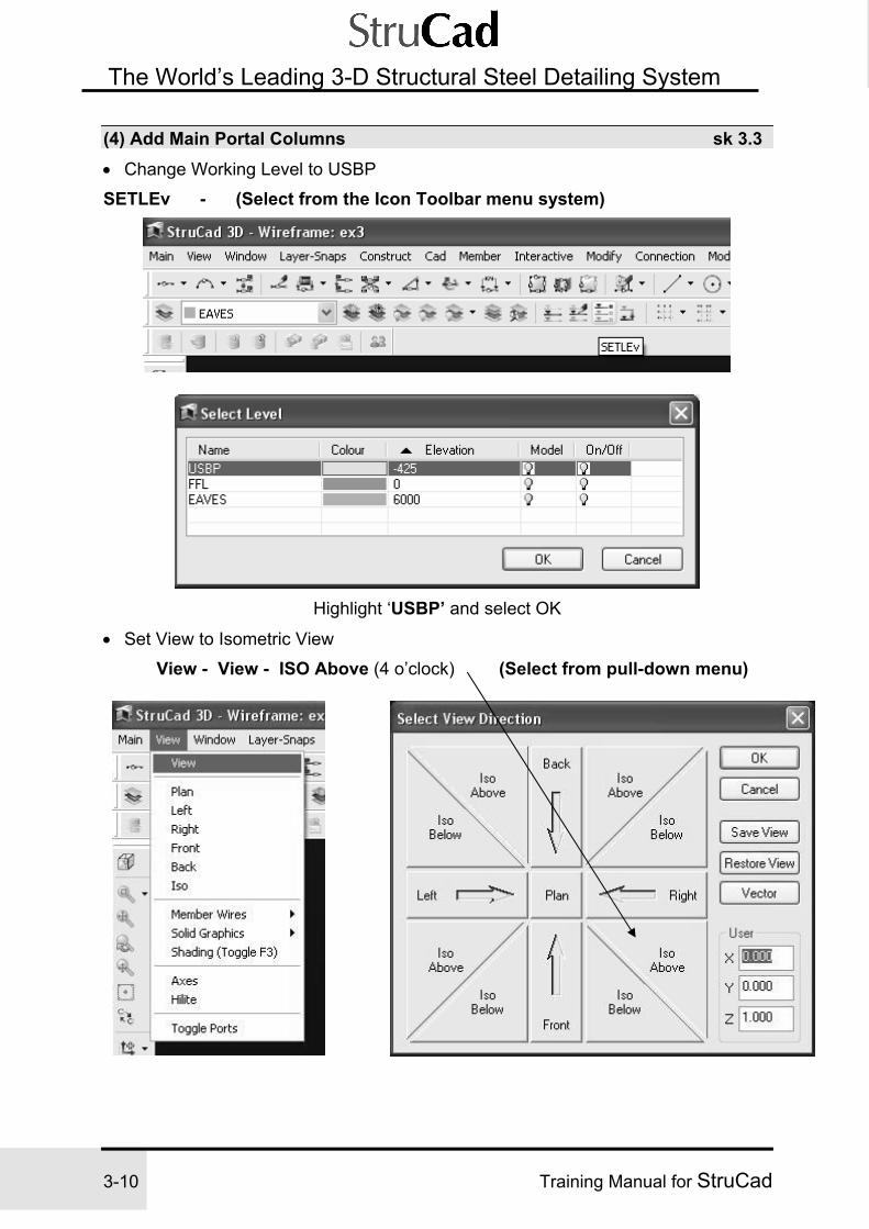
(4) Add Main Portal Columns sk 3.3 • Change Working Level to USBP
SETLEv - (Select from the Icon Toolbar menu system)
Highlight ‘USBP’ and select OK
• Set View to Isometric View
View - View - ISO Above (4 o’clock) (Select from pull-down menu)

Exercise 3 StruCad Portal Frame
Training Manual for StruCad 3-11
3
The World’s Leading 3-D Structural Steel Detailing System
• Set Layer for Columns (Note that layers are independent of levels, even though they were created together using ‘LAYERWiz’ )
SETLAy - (Select from the Icon Toolbar menu system)
The SETLAy command is invoked by opening the ‘Combo Box’ and selecting one of the displayed Layers, - Select – Columns
• Add Columns MEMber - (Select from the Icon Toolbar menu system) Stock Size ....... 457X191X67UB Rotation angle ... 180 - for Grid Line A only, 0 - for Grid Line C Start point .......... Intersection (of Grid Lines) End point ........... End (of Eaves Tie member ‘Wire’)
sk 3.3
Add Portal Columns

Exercise 3 StruCad Portal Frame
3-12 Training Manual for StruCad
The World’s Leading 3-D Structural Steel Detailing System
Column Rotation When columns on grids A & C both have 0° rotation, their UDS is the same as the world UDS and their TOP faces are both to the top of the screen. Consequently, when you connect a beam between the columns on Grid Lines C and A, the beam connects to the BOT face of the column on Grid Line C and the TOP face of the column on Grid Line A. This would result in the two columns being marked differently and therefore having separate fabrication details.
However, when you rotate the column on Grid Line A so that it has a rotation of 180°, the TOP face of the column stays towards the outside of the building. Connecting a beam between the two columns will now result in the connection being formed with the BOT face of both columns, therefore only giving the columns one erection mark and one fabrication detail.
You will also find that by keeping the TOP face of your column to the outside of the building, the cold rolled connection macros also work much better. By keeping your beams and columns symmetrical (wherever possible) you will have more success in keeping down the number of detail drawings produced, you will also find that your interactive connections (which will be covered later) will have a higher success rate, under more varied conditions. One other benefit is that it makes it easier to workout offsets of members, which you will see when it comes to offsetting our eaves ties later in this model.

Exercise 3 StruCad Portal Frame
Training Manual for StruCad 3-13
3
The World’s Leading 3-D Structural Steel Detailing System
(5) Add Portal Rafters sk 3.4 • Set Layer for Rafters
SETLAy - (Select from the Icon Toolbar menu system) Open the SETLAy ‘Combo Box’ and select the displayed Layer ‘Rafters’
• Change UDS (to make it easier to position the rafters) The UDS command changes the direction of the AXES (the x, y, z co-ordinate system that StruCad works to). At the moment this UDS is set to WORLD, i.e. with X running left to right, Y running bottom of screen to top, and Z running towards you as you look at the screen with the view at plan. (The WORLD UDS is ALWAYS Red)
UDS - Vector-Vector (Select from the Icon Toolbar menu system) (To position X and Y axes along two chosen vectors) See sketch SK 3.4
- Select Grid Line 1 (at Grid A end so that the X-axis points towards Grid C) - Select column on Grid A/1 (so that the Y-axis is vertical)

Exercise 3 StruCad Portal Frame
3-14 Training Manual for StruCad
The World’s Leading 3-D Structural Steel Detailing System
• Add Rafters
MEMber - (Select from the Icon Toolbar menu system) Stock Size .... 406x140x39UB Top of Steel .. ON (sloping member to have top flange on wire) Start point .... END End point ..... TYPE: @10000<17.5
(This will place a section 10000 long at 17.5° roof pitch)
NOTE - @ = Relative (i.e. the length of the wire) • Add Second Rafter
When inserting the second rafter opposite the first (see sk 3.4), either first change the UDS so the X-axis points towards Grid A or, when creating the member, adjust the End Point Angle to be 180-17.5°. = 162.5°
• Change UDS back to World
UDS – World (Select from the Icon Toolbar menu system)

Exercise 3 StruCad Portal Frame
Training Manual for StruCad 3-15
3
The World’s Leading 3-D Structural Steel Detailing System
• Trim Rafters at Apex See sk 3.5
Trim - (Select from the Icon Toolbar menu system)
Trim Rafters back to each other. Select a Rafter as an edge to trim against. Select the part of the other Rafter, which you want to trim. • Copy Members
Copy - (Select from the Icon Toolbar menu system) Copy Members using the ‘m’ option. Select members, Columns and/or Rafters, which are to be copied, and accept. (middle mouse button). The ‘prompt’ line will read as shown below
At this prompt, first type the letter ‘m’ and enter; you will then be asked again for a base point. Select a suitable Base Point, i.e. a grid intersection, and a copy of the members will be placed on each subsequently chosen new point. i.e. other grid intersections. (sk 3.5). Press the middle mouse button to finish.
Trim Rafters and Copy

Exercise 3 StruCad Portal Frame
3-16 Training Manual for StruCad
The World’s Leading 3-D Structural Steel Detailing System
The TOP OF STEEL Rule StruCad’s default positioning of members in relation to the wireframe are as follows:
The top two diagrams above show you that, for a HORIZONTAL member with the TOS flag OFF, the wireframe is the actual Top of Steel of the member, whether it is a UB, an RSA, an RSC, a CHS, a cold-rolled section or any other type of member. If, on the other hand, you want to work about the neutral axis of a horizontal member, then you must toggle the TOS flag to ON and it will then give you the wireframe on the centre line of most sections, such as a UB or a CHS; for an angle, it works to its Centre of Gravity.
For a cold rolled member, the rules are slightly different when you turn the TOS flag ON, as the member is then positioned “sat up” above the wireframe by the standard distance specified by the cold rolled manufacturer:
Standard distance, as specified bycold-rolled product manufacturer.Wireframe position

Exercise 3 StruCad Portal Frame
Training Manual for StruCad 3-17
3
The World’s Leading 3-D Structural Steel Detailing System
For SLOPING or NON-HORIZONTAL members (such as rafters and columns), the rule is the opposite - the default position is the neutral axis when the TOS flag is OFF (see diagram below). Obviously, when the TOS flag is toggled, the wireframe position will revert to the actual Top of Steel. This same rule applies to a member in the model that has a horizontal wireframe position, but its offsets actually make it a sloping member.
(6) Add Purlins to First Bay sk 3.6 • Create a Purlin Layer
Layer-Snaps - LAYER - New .......... Purlins , White
• Remove Columns from Visibility
Layer-Snaps - LAYER ......... Edit columns = OFF
• Change UDS to Plane of Roof
Construct - UDS - Entity .............(Select Rafter between Grids A&B)
• Window-in on Working Area
Window - Wi ................. Define window around working area

Exercise 3 StruCad Portal Frame
3-18 Training Manual for StruCad
The World’s Leading 3-D Structural Steel Detailing System
• Add Members
MEMber - Metsec – Z Purlin Stock Size ......... MS-172Z15 Top of Steel = ON (so that the purlin sits above the rafter) Start Point ......... REF, INT X = -250 End Point .......... PERP
• Add Rotation to Purlins
ALIgn - (Select from the Icon Toolbar menu system) Select Purlin. Select Alignment Point END/INT
• Copy Members
MCopy - (Select from the Icon Toolbar menu system) Select member Base point ........... INT / END New point ...... REL, X = -1800 Number of copies = 4
• Change UDS to World
UDS - (Select from the Icon Toolbar menu system) Select World

Exercise 3 StruCad Portal Frame
Training Manual for StruCad 3-19
3
The World’s Leading 3-D Structural Steel Detailing System
The Align Command The Align command is a construction tool that allows you to easily rotate a member to the plane of a roof, or to any point you choose. It will be used when we do the roof bracing.
The ALIgn command may be accessed from the Pull – down menu, from the top left floating menu or from the Icon Toolbar menu all as shown To get on-line help on the Align command, point to its command icon and press the middle button. The help will be displayed on the Pad. To execute the command, choose the member to align and then select the alignment point. The alignment point you choose MUST be in the positive X-axis of the member you wish to align (refer to your cube showing the local axes), but not at a connecting joint itself. For example, in the following sketch, the alignment point for purlin Member A would be the end of the rafter at Intersection Point 1. Purlin Member B would be aligned with the Apex of the second rafter, at Intersection Point 2.
For further information on the Align command please refer to the on-line help or the StruCad 3D Reference Manual.

Exercise 3 StruCad Portal Frame
3-20 Training Manual for StruCad
The World’s Leading 3-D Structural Steel Detailing System
NOTE
If you pick an incorrect point to which to align the member, then the rotation could be the angle of slope +180°, which will have serious consequences if the member is inverted.
The ARRay Command The ARRay command creates multiple copies of entities in either a rectangular or polar array. The polar array is very useful for creating members around the central point of a structure. You can also use the polar array to copy roof purlins from one side of a sloping roof to another.

Exercise 3 StruCad Portal Frame
Training Manual for StruCad 3-21
3
The World’s Leading 3-D Structural Steel Detailing System
(7) Input A Double Spanning Purlin System
Use Extend, Trim, Copy, etc, as learnt in previous exercises, to complete the nearside of the roof.
Layer-Snaps - LAYER ............ Edit Grid, Rafters, Eaves - Freeze = Yes
• Array Members to the far-side Roof Slope
TRIM - ARRay - (Select from the Icon Toolbar menu system) Open the sub-menu by selecting the ‘Down Arrow’ to the right of ‘TRIM’ Select - ARRay

Exercise 3 StruCad Portal Frame
3-22 Training Manual for StruCad
The World’s Leading 3-D Structural Steel Detailing System
Select .........Polar Select objects
Choose Visible, (we can do this because all other layers are frozen) and confirm selection with middle mouse button. Centre point of array - Select the Midpoint of Grid Line B (the centre of the building), using the ‘Midpoint’ snap option.
Number to copy .............1 Angle to fill ..............…180 degrees
NOTE: This rotates the members so that they have the correct rotation and offsets on the far-side roof.
(8) Add Bracing to Last Bay sk 3.7 • Create a Bracing Layer
Layer-Snaps - LAYER - (Select from the Icon Toolbar menu system)
Select - New .....….. Bracing Colour = Yellow

Exercise 3 StruCad Portal Frame
Training Manual for StruCad 3-23
3
The World’s Leading 3-D Structural Steel Detailing System
• Change Working View
Layer-Snaps - LAYER .............…….… Edit Purlins = OFF Fit ..................... Will fit all displayed entities to maximum window Wi ..................... Define window around working area (see sk 3.7)
• Add Members……..…... Stock Size .......... 88.9X3.2CHS Start point .......... INT / END End point .......... MID Start point .......... MID / INT /END / Last Point End point .......... INT / END Start point .......... MID / INT / END End point .......... MID / PERP
Note positions of CHS member icons in relation to Wireframe.
Layer-Snaps - LAYERS - Edit Rafters – Freeze = off

Exercise 3 StruCad Portal Frame
3-24 Training Manual for StruCad
The World’s Leading 3-D Structural Steel Detailing System
The offsetting of bracing member end-points MUST be done prior to aligning the members, since if you offset them after alignment you will have the wrong rotations.
Moving the Setting-out Points of Bracing
At present our bracing setting-out points (SOP) are on the centre line of our column (see diagram below). If we want to move the bracing SOP to, say, the face of the
column or up the rafter, we can use a command called SETBRACE which will automatically apply Global Offsets to one end of the member only.
Global Offsets Global Offsets enable you to offset the ends of a member in the directions of the World UDS axes. Use the member’s X offset at end A, Y offset at end A and Z offset at end A values to offset End A of the member in the global X, Y and Z directions, and its X offset at end B, Y offset at end B and Z offset at end B values to offset the member’s End B. For instance, if a member has an X offset at end A, value of 100, its A end will be offset from the wireframe position by 100mm in the World UDS X-direction. Global Offsets are not to be confused with a member’s Local Offsets, which are applied using XOFF and YOFF, and relate to the member’s local UDS (use HELPSHAPE or your cube to determine these from the relevant shape diagram). Normally, when bodily offsetting the whole of a member, you will apply either an XOFF or a YOFF. When you only need to offset one end of a member, or to apply different offsets to the A and B ends, you will use the global offset member attributes. The rafter bracing in this case has both types of offsets, a YOFF to drop the bracing down perpendicularly within the depth of the rafter, and both ADY and ADZ offsets to move the setting-out point from the centre-line of the column up the rafter’s slope.

Exercise 3 StruCad Portal Frame
Training Manual for StruCad 3-25
3
The World’s Leading 3-D Structural Steel Detailing System
Move SOP of Bracing Member at Rafter’s A end
Modify - Member adjusts - Setbrace
Select Roof Brace end ..…………Point
Select Rafter end ........…........ Point Enter plan distance along rafter ...300 This will apply the required Global Offsets automatically to the A end of the bracing member. Use MLIST to check the offset.
• Move SOP of Bracing Member at Rafter’s B end
Setbrace Select Roof Brace end ............... Point Select Rafter end ........................ Point Enter plan distance along rafter ...100
NOTE: There is no need to make this bracing SOP a negative value, since the software will apply the correct offsets based upon the members you select.

Exercise 3 StruCad Portal Frame
3-26 Training Manual for StruCad
The World’s Leading 3-D Structural Steel Detailing System
• Open up the SOP’s of the Triple Brace Connection
• Change the UDS to the Roof Slope
UDS - Entity - (Select from the Icon Toolbar menu system) Select Rafter …………This will change the working plane to align with the top flange of the Rafter.
• Draw in Construction Lines
Line - From Point REF/INT (of bracings and rafter) X= -100
To Point REL Y= 500 Repeat for the second construction line. (X = 100)

Exercise 3 StruCad Portal Frame
Training Manual for StruCad 3-27
3
The World’s Leading 3-D Structural Steel Detailing System
ENDAdjust - Eccent - (Select from the Icon Toolbar menu system)
Select member end ................... Point
Actual end point ..........................INT/END
Eccent ……………………….... Select member end .....................Point
Actual end point ..........................INT/END
Again, the member ends do not move - all that happens is that global offsets are applied to the bracing member’s ends to move their SOP’s apart. Use MLIST to check again.
Add Offsets and Alignment to Bracing
• Add Rotation to Brace Bar A See sk 3.8 and sk 3.9
Align - (Select from the Icon Toolbar menu system)
Select Bracing. Select Alignment Point INT
• Add Rotation to Brace Bar B
Align - (use middle mouse button) Select Bracing. Select Alignment Point INT or
• Add Rotation to Brace Bar C
Align - (use middle mouse button) Select Bracing. Select Alignment Point INT

Exercise 3 StruCad Portal Frame
3-28 Training Manual for StruCad
The World’s Leading 3-D Structural Steel Detailing System
• Add Offsets to Brace Bars
Edmem - (Select from the Icon Toolbar menu system)
Select all three bracings and confirm, using middle mouse button. Now edit the ‘Local Y Offset’ this will edit all three members at the same time.
Local Y Offset = -100 (to drop the bracing members perpendicular within the plane of the roof, i.e. 90° to the rafter)
Add Offsets and Alignment
sk 3.8
NOTE: Remember that the ALIGN command only works correctly in the member’s positive X-axis. Check your cube for the CHS member’s X-Y axis for aligning and offsetting purposes.

Exercise 3 StruCad Portal Frame
Training Manual for StruCad 3-29
3
The World’s Leading 3-D Structural Steel Detailing System
• Add Top of Steel Flag to Brace Bar B only See sk 3.9
Edmem - Top of Steel = ON. (this will position the horizontal member with the ‘wire’ on it’s neutral axis, the other two members are sloping, so the default position for the ‘wire’ on these members is also the neutral axis - See Below.)
Add T.O.S. to Member B Only
sk 3.9
Remember the Top of Steel Rule (here on CHS members)
Default position for anon-horizontal CHS
Default position for a horizontal CHS(applying TOS=ON will toggle this to
the Neutral axis)

Exercise 3 StruCad Portal Frame
3-30 Training Manual for StruCad
The World’s Leading 3-D Structural Steel Detailing System
• Mirror Bracing Members to Opposite Roof Slope
UDS - World - (Select from the Icon Toolbar menu system)
Align - MMirror - (Select from the Icon Toolbar menu system) Select Members A, B & C (Bracing Members)
First point of Mirror Line - INT/END
Second point of Mirror Line - INT/END
Check offsets in a RIGHT or LEFT side view (you can just type “right” or “left”).
NOTE: We use MMIRROR (Member Mirror) instead of a normal MIRROR command in this case. The MIRROR command is just used for mirroring lines or members that have no properties such as rotations, offsets or TOS flags set, because it ignores all of these. If you do have members with any such attributes set, then you must use MMIRROR. This will mirror the wireframe lines (as normal mirror does) and, in addition, will mirror the member attributes (which the normal mirror doesn’t).
• Mirror the Bracing Panels to the other end of the building (using MMIRROR).

Exercise 3 StruCad Portal Frame
Training Manual for StruCad 3-31
3
The World’s Leading 3-D Structural Steel Detailing System
(9) Add Gable Posts to Grid Line 8 sk 3.10 • Change Working Level
Setlev ........................... usbp
• Change Working View Wi .................................................. Define working window
• Remove Bracing from View
Set model layer to Columns using ‘Combo’ Box Layer-Snaps - LAYER .…........ Bracing = OFF
• Add Members Member - (Select from Icon Toolbar menu) Stock Size ...................254X146X31UB Rotation Angle = -90 (to keep top face to outside) Start point ...........REF, INT/END, Y = 5000 End point ............REL Z = 9000 (takes the Column past the rafter) Start point .............REF, INT / END, Y = -5000
End point ..............REL, Z = 9000

Exercise 3 StruCad Portal Frame
3-32 Training Manual for StruCad
The World’s Leading 3-D Structural Steel Detailing System
• Trim Members Back See sk 3.11
Trim - (Select from Icon Toolbar menu) Select Rafter, Select Column (Repeat for each Gable Post)
(10) Add Gable Posts to Grid Line 1 • Change Working View
FIT
• Copy Columns
COPY Select Gable Posts Base point .......... INT / END New point ......... INT / END
• Modify Gable Posts EDMem Select Columns Rotation angle = 90
(To keep TOP face to the outside)

Exercise 3 StruCad Portal Frame
Training Manual for StruCad 3-33
3
The World’s Leading 3-D Structural Steel Detailing System
(11) Add Portal Bracing Columns sk 3.12 • Use relevant commands to clarify working area, i.e. to change View, remove
Layers, or Window for clarity.
• Change to FFL Working Level
SETLev .......….….....…………....…….FFL (height given to Portal Beam is from FFL, i.e. Finished Floor Level)
• Create a Layer for the Portal Bracing
Layer-Snaps - LAYER - New .....PBRACE, Colour = Green
• Add Members (Column)
MEMber Stock Size .................... 305X165X40UB Rotation Angle ............ -90 Start Point ..................... END(Bottom of column on Grid A6) End Point ..................... REF, INT(grids A/6 at FFL) , Z = 4500
• Add Members (Beam)
MEMber Stock Size ..................... 305X165X40UB Start Point ..................... END (Top of Portal Brace Column) End Point ..................... PERP

Exercise 3 StruCad Portal Frame
3-34 Training Manual for StruCad
The World’s Leading 3-D Structural Steel Detailing System
View - PLAN • Determine Distance to Offset Portal Brace Column See sk 3.13
Select - WI, and ‘window in’ on plan view, as shown in sk 3.13
Dist - (Select from Icon Toolbar menu)
SNAPS ...... SOLID (so that we can measure to the member’s icon) 1st point ...... END Check SOLID snap is still on 2nd point ...... END
*** Make a note of the ‘X’ Value. *** (using the World UDS)
Note Highlighting, as shown, and using the control key and letter ‘C’ together, will copy the ‘X’ value.

Exercise 3 StruCad Portal Frame
Training Manual for StruCad 3-35
3
The World’s Leading 3-D Structural Steel Detailing System
• Modify Member Properties of Portal Brace column See sk 3.14
Edmem Select Portal Brace Column, and edit;- Local Y Offset = ‘X’ value of distance measured from sk 3.13
Note - The saved ‘X’ value may be retrieved by highlighting ‘Local Y offset’ and using the control key and letter ‘V’ together, this will re-call, and insert, the saved value. Compound ID = 2
Compound Identities (CompIds) are used when two or more members occupy the same wire position, or are within 15 degrees of each other. The StruCad software will only recognise them as different members if the CompIds are set differently. By default, the CompId is 1; for any other members occupying the same wire, their CompIds must be set to 2 or 3, etc.
Remove SOLID SNAPS after use
Snaps SOLID – Off
Accept

Exercise 3 StruCad Portal Frame
3-36 Training Manual for StruCad
The World’s Leading 3-D Structural Steel Detailing System
• Copy Portal Brace Column to Grid 5 and alter value of Rotation Angle (use EDMEM) See sk 3.15
• Rotate the member through 180° (i.e. change the rotation from -90 to 90). This allows us to leave the Y offset of the member as it is.

Exercise 3 StruCad Portal Frame
Training Manual for StruCad 3-37
3
The World’s Leading 3-D Structural Steel Detailing System
(12) Produce General Arrangement Drawings sk 3.12 As in Exercise 2, we must update the model before we can produce manufacturing information from it. The process of updating will automatically regenerate the model in solid format, unless the SOLToggle option is switched off.
Update - (Select from the Icon Toolbar menu system)
Marking will NOT automatically be done when Update (or any other modelling command) is run (unless you have specially set the CADMODES option for AUTOMATIC MARKING to Yes). Before you can create any GAs you must mark the model - either by using the MARK command, or by responding to the marking prompt when it is displayed. Remember that, after updating the model you can choose to view the structure in either solid or wireframe format by using the DISPLAY, UNDISPLAY and SOLToggle commands, all as described in section 15 of Exercise 2.
Model after Updating
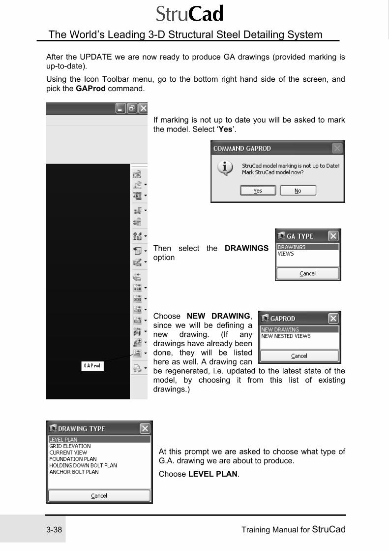
Exercise 3 StruCad Portal Frame
3-38 Training Manual for StruCad
The World’s Leading 3-D Structural Steel Detailing System
After the UPDATE we are now ready to produce GA drawings (provided marking is up-to-date). Using the Icon Toolbar menu, go to the bottom right hand side of the screen, and pick the GAProd command.
If marking is not up to date you will be asked to mark the model. Select ‘Yes’.
Then select the DRAWINGS option
Choose NEW DRAWING, since we will be defining a new drawing. (If any drawings have already been done, they will be listed here as well. A drawing can be regenerated, i.e. updated to the latest state of the model, by choosing it from this list of existing drawings.)
At this prompt we are asked to choose what type of G.A. drawing we are about to produce.
Choose LEVEL PLAN.

Exercise 3 StruCad Portal Frame
Training Manual for StruCad 3-39
3
The World’s Leading 3-D Structural Steel Detailing System
A dialog box will now appear requesting the parameters for the drawing.
• Producing a Level Plan The first drawing we will produce is a level plan (e.g. a roof plan).
NOTE: In order to produce Level Plans in any model, there has to be levels set in that model for the programme to use. In this case we have three levels set, one of which we will use to create a Roof Plan. It is important to select the correct level to use, as this will affect the ‘Depth of Clip’ value, which we need to define in the Level Plan dialog box. Of the levels we have in this model, it would make most sense to use the ‘Eaves’ level for this purpose .
In the Level Plan dialog box you can now define the following:
Drawing Name - This is the drawing reference, which is generally a number that the drawing will be saved as, but whatever name is used must not contain any spaces.
Drawing Title - This will be a description of the drawing
Drawing Scale - The scale of the drawing
All / Select - ALL, will allow all members which are in the model, and defined by the ‘depth of clip’, to be shown.
-SELECT will allow the user to select those members, which are to be shown on the drawing
Depth of Clip -This defines how much of the structure is to be shown on the
drawing. For a Level Plan you need to define how much of the structure, in height, is to be shown. For a Grid Elevation you need to define how much of the structure, horizontally, is to be shown. For a Roof Plan we need to show all of the steel between the Eaves and Apex of the model. This vertical dimension may be measured from the model, before opening the dialog box. In our model this dimension is 2364.74mm, which we will round up to 2400mm. It does not matter if the dimension we use is larger, but it would matter if it were smaller. The direction of the clip is also important. For a Roof Plan, the view is from above, and in our case, the level we are using is the Eaves level, which means that in order to see the Apex, the depth of clip needs to have a negative value, as the apex is closer to the viewing point than the base level. i.e. the Eaves level.
Single / Solid - This determines the representation of the steel on the drawing
as either a single line, or as a full solid format
Parameter File - This defines which parameter file is to be used in the creation of the drawing. Generally the default gadps is the one to use.

Exercise 3 StruCad Portal Frame
3-40 Training Manual for StruCad
The World’s Leading 3-D Structural Steel Detailing System
Fill in as above and ACCEPT, a dialog box will then appear asking which labels to apply to the GA:
Accept the defaults. (Again, you can always produce new drawings with different options later on. Or try some here to see what the results are.)
Remember that, even after a drawing has been produced, you can always go back to GAPROD later and regenerate it, changing any of the options to suit, e.g. scale of drawing:
GAPROD then needs you to define the level to be drawn. As explained previously, we choose the EAVES level as our datum, which, with a depth of clip of –2400 will show any members that are within 2400mm above the datum Eaves level.

Exercise 3 StruCad Portal Frame
Training Manual for StruCad 3-41
3
The World’s Leading 3-D Structural Steel Detailing System
To save the configuration of the GA without actually producing the drawing, you would select the SAVE option. Normally, however, you should select the SAVE and RUN option -this will save the definition and create the drawing. Do this now.
• View the Level Plan To view the drawing, go to the bottom right hand corner of the screen, and select the ‘down arrow’ to the right of the GAProd command. This will open a small sub-menu as shown.
Choose GASdraw. A list of all the GA drawings that have been produced will appear. Choose the drawing you have just created. The View Drawings environment will then be opened automatically, and the selected drawing will be displayed for you.
If you are linked to a printer or plotter, you can plot out the drawing as an example:
Utility - Plot (Select from pull-down menu)
• Produce a Section View For the next example we will create a GA of a section through the building that is a view on a grid line, in this case, Grid Line 1.
Follow the same route as before, GAProd, Drawings, New Drawing but at the drawing type dialog select the GRID ELEVATION option.
Complete the Grid Elevation dialog in a similar manner to the Level Plan dialog. If you only want to see the steel which is on the grid line, make depth of clip = 0, if you want to see rafters, purlins etc, then make the depth of clip = 7500, this will show all steel up to the centre of the building.
Note that the depth of clip is positive on this occasion as the clip is extending in the direction of the view.

Exercise 3 StruCad Portal Frame
3-42 Training Manual for StruCad
The World’s Leading 3-D Structural Steel Detailing System
When you have accepted the two dialog boxes, the prompt will then ask you to select a grid line. Select Grid Line A. The prompt will then ask you to select a viewpoint to indicate which direction you are viewing in, i.e. From outside of the building in, or from inside the building out. Select the end of Grid 5, outside of the building. Again, to view the drawing, go to GASDRAW as shown in the above example.
• Further Exercises 1. Produce a plan view on FFL that shows the column locations. 2. Produce an elevation view on Grid Line A showing the rafter members. A suitable
depth of clip will be required in order to include the rafters, where +ve is away from viewpoint.
3. Produce a Gable Elevation on Grid Line 8. Note. In order to show the purlins on the Gable Elevation the depth of clip will need a value greater than 0.
4. Produce a Section Through the building, but remember the depth of clip value as above.
5. Produce material lists for the job (as described in Exercise 2).
Further ‘CLIP’ Explanation A positive depth of clip for a level plan will show steel below the level you have chosen.
A negative depth of clip for a level plan will show steel above the level you have chosen
A positive depth of clip for an elevation will show steel in the direction of view from the grid line you have chosen
A negative depth of clip for an elevation will show steel opposite to the direction of view from the grid line you have chosen

Exercise 3 StruCad Portal Frame
Training Manual for StruCad 3-43
3
The World’s Leading 3-D Structural Steel Detailing System
(13) Produce Material Lists
MATList - (Select from the Icon Toolbar menu system)
Select the ‘down arrow’ to the right of the MATList command and open the sub-menu as shown. Select - MATRtf
You may be informed that the model marking is not up to date, if so, choose ‘YES’ to mark the model. Alternatively, or after marking is complete, another menu will appear giving the option of making the reports revision controlled. Select ‘Yes’.
This will now run and open Material Listing Manager, as shown
Place cursor over ‘System’ and use right mouse button to open the options table as shown. Select Setup/Run Reports.

Exercise 3 StruCad Portal Frame
3-44 Training Manual for StruCad
The World’s Leading 3-D Structural Steel Detailing System
The Report Filter Criteria table, as shown, will now open with the option of running reports for the whole contract, or for Selected User Attributes.
The ‘Selected User Attribute’ option will allow reports to be run for any group of members that have a common attribute. As each attribute is selected the values assigned to the members in the model will be displayed. The relevant value can then be selected. Choose the ‘All Contract’ option, and select ‘OK’ This will now open a Report Selection Table, displaying all the types of reports, which are available for production. As many reports as are required can be run at the same time by ‘ticking’ the appropriate boxes. Reports may also be printed as they are generated by ‘ticking’ the ‘Auto Print’ option

Exercise 3 StruCad Portal Frame
Training Manual for StruCad 3-45
3
The World’s Leading 3-D Structural Steel Detailing System
Choose ‘All Members by Section’ and select ‘OK’

Exercise 3 StruCad Portal Frame
3-46 Training Manual for StruCad
The World’s Leading 3-D Structural Steel Detailing System
The Material Listing Manager will now re-appear with the lists, which have been run being displayed in the window.
To view or print - Place the cursor over the appropriate list and depress the right mouse button, this will open a selection table as shown. Select the required option, in this case it will be ‘View’ and pick with left mouse button, the list will then open in ‘Word’ format, as shown below.
If the ‘Print’ option is selected with left mouse button, this will send the list direct to your default printer.
Batch Selection To print or view several lists together, they can be ‘batch selected’ by highlighting all the required lists, either one at a time with the control key depressed, or as an unbroken list by selecting the top list, holding down the shift key, and selecting the bottom list. Continue to print or view as with a single list.
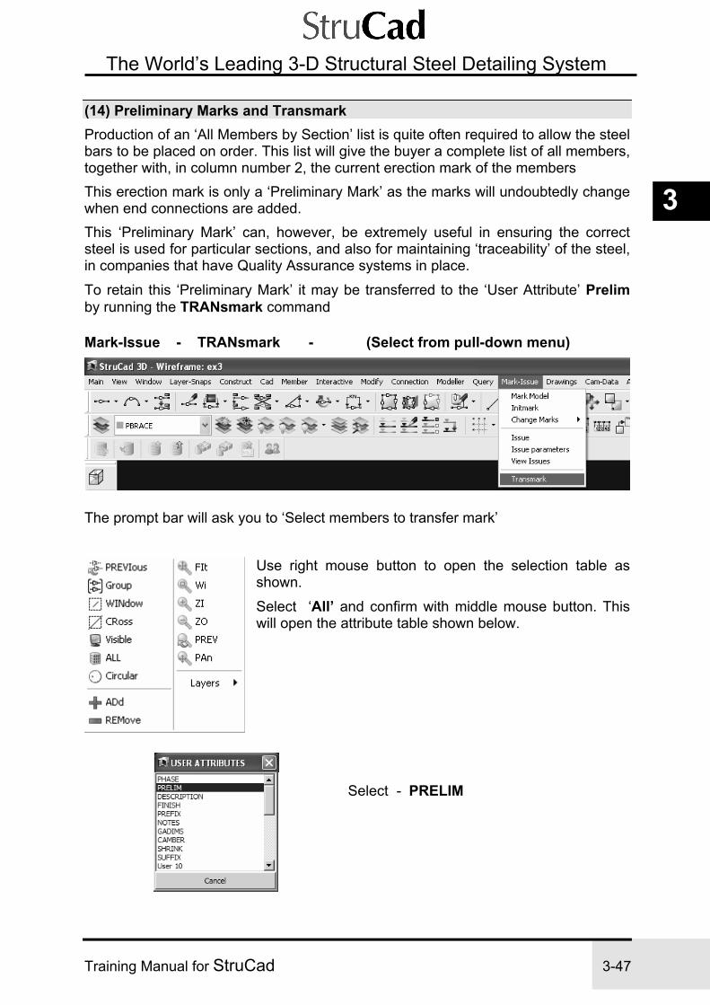
Exercise 3 StruCad Portal Frame
Training Manual for StruCad 3-47
3
The World’s Leading 3-D Structural Steel Detailing System
(14) Preliminary Marks and Transmark Production of an ‘All Members by Section’ list is quite often required to allow the steel bars to be placed on order. This list will give the buyer a complete list of all members, together with, in column number 2, the current erection mark of the members This erection mark is only a ‘Preliminary Mark’ as the marks will undoubtedly change when end connections are added. This ‘Preliminary Mark’ can, however, be extremely useful in ensuring the correct steel is used for particular sections, and also for maintaining ‘traceability’ of the steel, in companies that have Quality Assurance systems in place.
To retain this ‘Preliminary Mark’ it may be transferred to the ‘User Attribute’ Prelim by running the TRANsmark command
Mark-Issue - TRANsmark - (Select from pull-down menu)
The prompt bar will ask you to ‘Select members to transfer mark’
Use right mouse button to open the selection table as shown.
Select ‘All’ and confirm with middle mouse button. This will open the attribute table shown below.
Select - PRELIM

Exercise 3 StruCad Portal Frame
3-48 Training Manual for StruCad
The World’s Leading 3-D Structural Steel Detailing System
You will now be asked to confirm your instruction to ‘Transfer Marks for the selected members to the user attribute “PRELIM”. Select ‘Yes’ This is followed with a warning that any existing values currently attached to the selected user attribute will be over-written, and asking if you wish to continue. Select ‘Yes’ The transfer is now complete, and can be checked by selecting the command ‘EDUsr’ from the icon toolbar menu.
You may now select any member in the model and view the User Attributes of that member. The only attribute, which will have a value, will be ‘Prelim’
Later in the course we will see how we can use this information to help in keeping control of revisions.

Exercise 3 StruCad Portal Frame
Training Manual for StruCad 3-49
3
The World’s Leading 3-D Structural Steel Detailing System
NOTES

Exercise 3 StruCad Portal Frame
3-50 Training Manual for StruCad
The World’s Leading 3-D Structural Steel Detailing System
NOTES

Exercise 4 StruCad Macro Connections
Training Manual for StruCad 4-1
4
The World’s Leading 3-D Structural Steel Detailing System
Exercise 4
MACRO CONNECTIONS PRINCIPLES AND EXAMPLES
(Use model from Ex3)
Exercise 4 adds connections to the portal frame structure that you made in Exercise 3, checks the model and produces more drawings of it.
MACROS CONSIDERED
(1) Rectangular Base Plate Connection - rbp
(2) METSEC Purlin Connections - msp
(3) Rafter Eaves Haunch Moment End Plate - hmep
(4) Rafter Apex Moment End Plate - amep
(5) Roof Gusset Plate Bracing - gpb

4-2 Training Manual for StruCad
(6) Eaves Tie General End Plate - gep
(7) Check for Clashes of Steelwork
(8) Produce Drawings
(9) Convert Drawings to DWG/DXF/DWF and PDF Formats
(10) Labelling Drawings and Details using LABDEt
Introduction
Throughout this exercise, all the changes, which we make to the graphically produced macros, are designed to give examples of how the macros can be changed to produce the connection required. The first page of a G.U.I. macro acts as a ‘filter’ to disregard those parts of the macro, which are irrelevant to your particular application. This makes the macro easier to use and understand. There are still a few macros, which have not yet been changed to the new graphical format. For all of these macro connections you will need to use the On-line Help to get a better understanding of the changes you are making. The only way of becoming proficient with the macros is by experience; only look for the parameters you want to change, and ignore all the rest, as most options will be irrelevant to the connection you require.

Exercise 4 StruCad Macro Connections
Training Manual for StruCad 4-3
4
The World’s Leading 3-D Structural Steel Detailing System
Exercise 4
MACRO CONNECTIONS
HINT Whenever you need to remove an unwanted or faulty connection, you must replace it with a null connection, to ensure that all traces of the previous connection are removed.
Layer – Off (Pick portal brace column member icons) Accept defaults
PROCEDURES
(1) Rectangular Base Plate Connection (Create New LOCAL RBP1) (Use model from Exercise 3)
Create Base Plate Macro
Macpar - (Select from the Icon Toolbar menu system) The MACPAR command will allow you to create a new standard connection set up to your requirements.
When you select MACPAR, a dialog box will appear with all the macro connections available within StruCad, broken down into relevant connection categories, and listed in alphabetical order.
Select the General Purpose or Base and Top category, and click the RBP Rectangular Base Plate macro button.
To select the on-line Help

4-4 Training Manual for StruCad
Select the on-line help by clicking the Help button; the help diagram may need positioning. (Click on the help diagram’s top bar, then hold down the left mouse button and move the box)
Close the help and click the Next> button. Another dialog will appear which contains a list of the master set-ups available for the RBP macro. We now wish to create a new version of the macro, and we must make a copy since you cannot edit the master macros. Move the mouse cursor over the top of existing Global Macro, rbp, (making sure the macro highlights in blue) and click the right-hand mouse button.
Choose Copy to Local. The macro will automatically allocate a macro number (the next available one) for the local copy and, when you press OK, will make the copy.
You will then see the new local macro - (rbp1 in this case) - in the Local Macros list. Double-click on this new macro.

Exercise 4 StruCad Macro Connections
Training Manual for StruCad 4-5
4
The World’s Leading 3-D Structural Steel Detailing System
This will open the Macro as a ‘Graphical User Interface’ (G.U.I.) in which the parameters of the local rbp1 connection macro can be defined and modified:
NOTE: Each of the ports on this opening page can be edited to suit the requirements of the base plate design. As each port is edited the ‘Tabs’ at the top of the page will change, some may disappear, and additional ones may appear. This selection process means that only those set-up files, which need to be edited, will become accessible. You can quickly access these files by clicking the appropriate tab. (Modify the parameters of this macro to match those shown on the following two pages.)

4-6 Training Manual for StruCad
Range tables for both Depth and Width of column may be edited as shown above. Additional ranges can be created by inserting a new range limit in the available box, and then selecting the + button. Ranges which are not required may be deleted by inserting the range limit in the box and selecting the – button. The only criteria which limits the number of ranges, which you can use, is that some of the fields do not have variable values, as follows: - 1. Base Plate Thickness. 2. Holding Down Bolt Details. 3. Weld Parameters. 4. Base Plate Material Grade

Exercise 4 StruCad Macro Connections
Training Manual for StruCad 4-7
4
The World’s Leading 3-D Structural Steel Detailing System
When complete, choose the Exit button on the dialog, and say yes to save changes.

4-8 Training Manual for StruCad
• Apply Base Plate to Columns See Sketch sk 4.1
Endtype - (Select from the Icon Toolbar menu system) This will allow you to apply the created base connection to the relevant members.
Select LOCAL MACROS from the menu of options that is displayed.
A Local Macro dialog will appear. This will allow you to select from your local macros.
Select the Local Macro rbp1 (this is the macro that we customised to reproduce the base plate in sketch sk rbp1). You will then be asked to Select Member Ends to which the base plates are to be applied.

Exercise 4 StruCad Macro Connections
Training Manual for StruCad 4-9
4
The World’s Leading 3-D Structural Steel Detailing System
Select all Column Ends at the bottom. This will apply the connection rbp1 to the members. (Clicking anywhere on the member below the arrow will go to the base of the member; clicking anywhere above the arrow will go to the top of the column.)
Update the Model
Modeller - Update (Select from drop-down menu) UPDATE passes all the wireframe member’s information to the model’s database. Once we have updated our model, we can access this database graphically by using LOADJOINT to allow us to view individual joints. Alternatively, we can view the whole model, or just selected members, by using DISPLAY / UNDISPLAY.
• Load the Joint Single-click with the right hand mouse button on the base of a member (e.g. the column on Grid A1). An object-driven menu will appear - select - LOADjnt.
View the connection. Slist, (From the object driven menu system) will allow you to check the properties of your plate, bolts etc. Alternatively you can measure distances manually.
• Return to Wireframe
Main - UNLOADJNT (Select from drop-down menu)
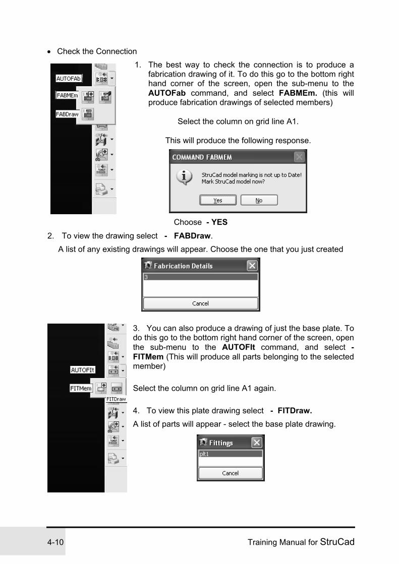
4-10 Training Manual for StruCad
• Check the Connection 1. The best way to check the connection is to produce a
fabrication drawing of it. To do this go to the bottom right hand corner of the screen, open the sub-menu to the AUTOFab command, and select FABMEm. (this will produce fabrication drawings of selected members)
Select the column on grid line A1.
This will produce the following response.
Choose - YES
2. To view the drawing select - FABDraw. A list of any existing drawings will appear. Choose the one that you just created
3. You can also produce a drawing of just the base plate. To do this go to the bottom right hand corner of the screen, open the sub-menu to the AUTOFIt command, and select - FITMem (This will produce all parts belonging to the selected member)
Select the column on grid line A1 again.
4. To view this plate drawing select - FITDraw.
A list of parts will appear - select the base plate drawing.

Exercise 4 StruCad Macro Connections
Training Manual for StruCad 4-11
4
The World’s Leading 3-D Structural Steel Detailing System
This will open the base plate drawing
Main – Exit – Select from the Pull-Down Menu - To close the drawing and return to the StruCad model.

4-12 Training Manual for StruCad
(2) METSEC Purlin Connections (Use standard METSEC connections supplied)
• Create Purlin Connection Macros
Macpar - (Select from the Icon Toolbar menu system) (Also accessible from the Connection drop-down menu)
Select METSEC category and then METPAR
Select MSP – ZED / C Purlin to Rafter
Make 4 Local copies of the Global Macro, msp, as shown. Each of these macros will be edited to produce a different connection.

Exercise 4 StruCad Macro Connections
Training Manual for StruCad 4-13
4
The World’s Leading 3-D Structural Steel Detailing System
Edit local Macro msp1 – as follows; - Highlight the macro by selecting with the left hand mouse button and select Edit.
General – Edit the macro title, Metsec Basic, to read No Sleeve No Stay as shown. Now select the next ‘Tab’ Cleat Type.
Select – Weld On Plate, and then move to next ‘Tab’ PLATE Cleat.

4-14 Training Manual for StruCad
Edit – Weld Electrode Grade and Weld Electrode Specification, as shown. Note; Investigate the available options for welds, fitting grades and the introduction of the use of a stiffener plate. Select next ‘Tab’ Sleeve + Rafter Stays.
Edit - Remove activation ‘ticks’ from ‘Rafter Stay’ and ‘Use Sleeve’ check boxes. Select next ‘Tab’ Gable End.

Exercise 4 StruCad Macro Connections
Training Manual for StruCad 4-15
4
The World’s Leading 3-D Structural Steel Detailing System
Edit – Gable End Overhang, change to 305. Select next ‘Tab’ Cleaders.
Edit - No editing required. Select last ‘Tab’ Man Lock Hole.

4-16 Training Manual for StruCad
Edit - No editing required. Return to first page - select ‘General’.
The General, or front, page will now look like this. The macro can now be saved. - Select OK. The remaining three macros may now all be edited in turn.

Exercise 4 StruCad Macro Connections
Training Manual for StruCad 4-17
4
The World’s Leading 3-D Structural Steel Detailing System Select local Macro msp2, highlight the macro by selecting with the left hand mouse button and select Edit.
General – Edit the macro title, Metsec Basic, to read No Sleeve With Stay. Now select the next ‘Tab’ Cleat Type.
Select – Weld On Plate, as with msp1 and then move to next ‘Tab’ PLATE Cleat.
Edit – Weld Electrode Grade and Weld Electrode Specification, to be the same as for msp1. Select next ‘Tab’ Sleeve + Rafter Stays.
Select next ‘Tab’ Gable End.

4-18 Training Manual for StruCad
Edit – Gable End Overhang, change to 305, edit Gable End Hole.
The Cleaders and Man Lock Hole pages do not require any editing, as with msp1. Return to first page - select ‘General’.
The General, or front, page will now look like this. The macro can now be saved. - Select OK.

Exercise 4 StruCad Macro Connections
Training Manual for StruCad 4-19
4
The World’s Leading 3-D Structural Steel Detailing System Select local Macro msp3, highlight the macro by selecting with the left hand mouse button and select Edit.
General – Edit the macro title, Metsec Basic, to read With Sleeve No Stay. Now select the next ‘Tab’ Cleat Type.
Select – Weld On Plate, as with msp1 and then move to next ‘Tab’ PLATE Cleat.
Edit – Weld Electrode Grade and Weld Electrode Specification, to be the same as for msp1. Select next ‘Tab’ Sleeve + Rafter Stays.
Edit - check the box only for ‘Use Sleeve’ option. Select next ‘Tab’ Gable End.

4-20 Training Manual for StruCad
Gable End – No changes are required as this Macro is for a sleeved connection and will not be applied to Gable End connections.
The Cleaders and Man Lock Hole pages do not require any editing, as with msp1. Return to first page - select ‘General’.
The General, or front, page will now look like this. Select OK.
Select local Macro msp4, highlight the macro and select Edit.
General – Edit the macro title, Metsec Basic, to read With Sleeve With Stay. Now select the next ‘Tab’ Cleat Type.

Exercise 4 StruCad Macro Connections
Training Manual for StruCad 4-21
4
The World’s Leading 3-D Structural Steel Detailing System Select – Weld On Plate, as with msp1 and then move to next ‘Tab’ PLATE Cleat.
Edit – Weld Electrode Grade and Weld Electrode Specification, to be the same as for msp1. Select next ‘Tab’ Sleeve + Rafter Stays.
Sleeve + Rafter Stays - No changes required as this macro will provide both sleeves and stays. Select next ‘Tab’ Gable End.
Gable End – No changes are required as this Macro is for a sleeved connection and will not be applied to Gable End connections.
The Cleaders and Man Lock Hole pages do not require any editing, as with msp1. Return to first page - select ‘General’.
The General, or front, page will now look like this. - Select OK.

4-22 Training Manual for StruCad
Select required Purlin Ends and apply local macro - as shown on the two following sketches. (Set view to PLAN; turn off any layers you do not want to see at this time)

Exercise 4 StruCad Macro Connections
Training Manual for StruCad 4-23
4
The World’s Leading 3-D Structural Steel Detailing System
You have now applied sleeves to all the purlin connections on one side of the roof, except where they connect to the rafters on Grids 1 & 8, where a butted connection is sufficient. The second line of purlins up the slope additionally has rafter stays at every connection. Although we have used a standard set-up, you can still (if required) create your own local macros, and change any of the parameters to suit your company requirements, or those of the engineer. The most common things you may want to change will be the overhang at the end bays (which defaults to 500), and the type of fixing required to the rafter, either a plate or a cleat. • Repeat for the Other Side of the Roof. • Update the Model to Observe any Changes. Update Loadjoint (to observe the different types of connections applied) Select the Current Member (so that you can WI, ZI, ZO etc) Unloadjnt (when ready to leave the connection)
• Observe a Connection Between a Double-Spanning Purlin and a Rafter.
Loadjoint (You will see that there is no connection present - the reason for this is that there is no member end at this joint in the model. Endtypes can only be applied to Member Ends.)
To be able to form a connection at this joint we need to create an artificial member end - to do this we use what we call ‘Dummy Members’, which are here used to form the purlin connection to the rafter. Dummy members are not given an Erection Mark and thus do not have Fabrication Drawings produced for them, nor do they show up on material lists (see Reference Manual, Section 4.1 for more information about using Dummy Members).
• Add Dummy Members Member - More Members - Dummy (Select from pull-down menu) Displacement - 0 Endtype - msp1 * (Enter from keyboard) CompID - 2 (Dummy on top of main member) Dummy Length - 500 Connection Point - I (Intersection of rafter and purlin)
* Note: The second line of purlins up from the eaves requires stays; therefore the endtype msp2 will be required for this connection.

4-24 Training Manual for StruCad
Select Common Member - Select the Rafter A (on Grid 2) Select Member to Receive Dummy- Select Purlins 1, 2 & 3 and confirm selection with middle mouse button. Now add Dummy Members to the next Rafter. Select middle mouse button to return the dummy member command. You will notice that the previous settings have been retained. Select Common Member - Select the Rafter B (on Grid 3) Select Member to Receive Dummy- Select Purlin 4 and confirm. Select middle mouse button to return the dummy member command again. Edit settings to change end type from MSP1 to MSP2. ( see note ) Select Common Member - Select the Rafter B (on Grid 3) Select Member to Receive Dummy- Select Purlin 5 and confirm.
This will insert a Dummy Member at the three positions on this rafter where we
have continuous purlins that need to be connected to the rafter. Each dummy member will have the same rotation, offsets, etc that have been applied to the main purlin. You can now either repeat the Dummy command for each rafter where the purlins are continuous, or you can copy one of your dummy purlins to each position where it is required. Make sure that you complete both sides of the roof. – UPDATE & Check connections

Exercise 4 StruCad Macro Connections
Training Manual for StruCad 4-25
4
The World’s Leading 3-D Structural Steel Detailing System (3) Rafter Eaves Haunch Moment End Plate (Create New LOCAL HMEP1)
(Use model from Exercise 3) • Create Eaves Haunch Macro See Sketch sk hmep1 and Set-up File HMEP1.DAT
Macpar - (Select from the Icon Toolbar menu system) (Also accessible from the Connection drop-down menu) Select General Purpose or Haunch category and then HMEP macro.
Right-click HMEP; Copy to Local to create a new local version Name as: HMEP1 Modify Local HMEP1 – to achieve connection as shown below (all as following diagrams)

4-26 Training Manual for StruCad
General Edit the first page of the Macro above by changing the following:
1. Haunch Cut from – Cut
2. Stiffen Beam – Stiffener
3. Extra Bolts – No
4. Depth Option – Max Cut
5. Length Option – Length
6. Horizontal/Sloping – Sloping
7. Cap Plate/Stiffeners – Cap Plate
8. Project/Flush – Project
9. Extend Col. Top – Yes

Exercise 4 StruCad Macro Connections
Training Manual for StruCad 4-27
4
The World’s Leading 3-D Structural Steel Detailing System
Haunch Cut From Beam Edit Macro as follows:
1. Haunch Size – Rafter
2. Col. Rotation – No
3. Haunch Length – 1200
4. Bolt Centres, for range 200 (Column Flange = 191mm wide) = 90
End Plate Welds - No change

4-28 Training Manual for StruCad
Stiffener Options Edit Macro as follows:
1. Stiffen Col. Flange – Bottom
1a. Partial/Full Depth – Full
1b. Crop for radius. – 12
2. Shear Stiffener – Morris B
2a. Plate Details – Accept Default
2b. Crop for radius. – 12
3. Stiffeners – Col.
3a. Stiffener Shape – Rect
4a. Edit Stiffeners – Top = 2
Bot = 0
Cap Plate - No change

Exercise 4 StruCad Macro Connections
Training Manual for StruCad 4-29
4
The World’s Leading 3-D Structural Steel Detailing System
Stiffener Edit Macro as follows :
Edit Crop for root radius – 12
Miscellaneous - No change Exit and Save.
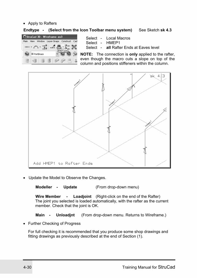
4-30 Training Manual for StruCad
• Apply to Rafters
Endtype - (Select from the Icon Toolbar menu system) See Sketch sk 4.3
Select - Local Macros Select - HMEP1 Select - all Rafter Ends at Eaves level
NOTE: The connection is only applied to the rafter, even though the macro cuts a slope on top of the column and positions stiffeners within the column.
• Update the Model to Observe the Changes. Modeller - Update (From drop-down menu) Wire Member - Loadjoint (Right-click on the end of the Rafter) The joint you selected is loaded automatically, with the rafter as the current
member. Check that the joint is OK. Main - Unloadjnt (From drop-down menu. Returns to Wireframe.)
• Further Checking of Progress
For full checking it is recommended that you produce some shop drawings and fitting drawings as previously described at the end of Section (1).

Exercise 4 StruCad Macro Connections
Training Manual for StruCad 4-31
4
The World’s Leading 3-D Structural Steel Detailing System
(4) Rafter Apex Moment End Plate (Create New LOCAL AMEP1) (Use model from Exercise 3)
• Create Apex Haunch Macro See Sketch sk amep1 and Set-up Diagrams
Connection - Macpar (Select from drop-down menu) Select General Purpose or Haunch category and then AMEP macro
Right-click on AMEP and create New Local copy Name as: AMEP1 Modify Local AMEP1 – double click on local AMEP1 - to achieve connection as shown below ( all as following diagrams )
180 x 12 Plate
20 Dia Bolts at 90 c/crs

4-32 Training Manual for StruCad
General Edit Macro as follows:
1. Edit mode – Manual
2. Haunch Cutting – Cut/Beam
3. Stiffeners – Nil
4. Depth Option – Depth
5. Length Option - Length

Exercise 4 StruCad Macro Connections
Training Manual for StruCad 4-33
4
The World’s Leading 3-D Structural Steel Detailing System
Haunch Cut From Beam:
1. Haunch Size – Rafter
2. Haunch Length – 750
3. Haunch Depth – 700
4. Edit Bot Plate Proj. – 25
5. Edit Top Bolt Centres (Vert) – 120
6. Edit Bolts Required – Top = 2
Bot = 3
7. Edit Bolt Cross Centres – Edit range 170 (Rafter Flange = 140mm wide)
Bolt Centres = 90
End Plate Welds - No change
Miscellaneous - No change
Exit and Save:

4-34 Training Manual for StruCad
• Apply to Rafters
Endtype - (Select from the Icon Toolbar menu system) See Sketch sk 4.4
Select - Local Macros Select - AMEP1 Select both Rafter Ends at each apex
• Update and check as for previous connections.
Produce and view representative fabrication drawings and check.

Exercise 4 StruCad Macro Connections
Training Manual for StruCad 4-35
4
The World’s Leading 3-D Structural Steel Detailing System
(5) Roof Gusset Plate Bracing (Create New LOCAL GPB1) (Use model from Exercise 3)
• Create Bracing Macro see sketch sk gpb1
Connection - Macpar (Select from drop-down menu) Select General Purpose or Bracing Category, then select GPB connection macro.
Right-click on GPB and create a New Local copy Name as: GPB1 Modify Local GPB1 to achieve connection as shown below (As per diagrams shown on following pages)
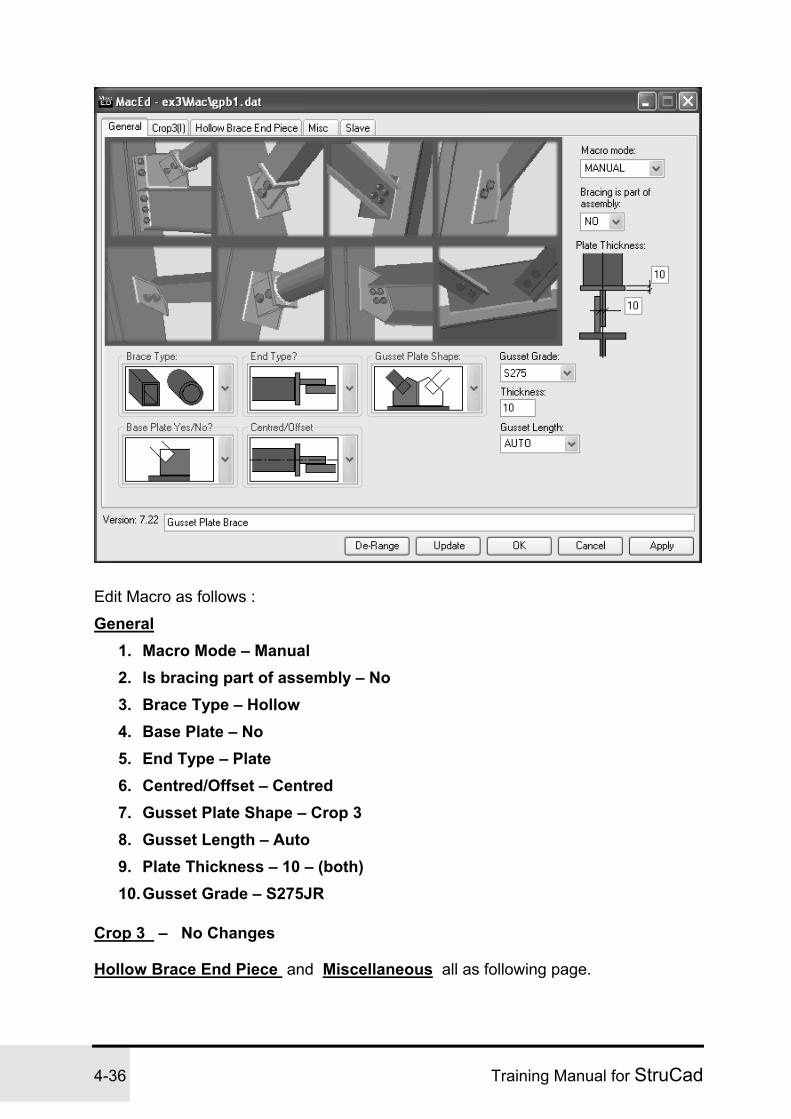
4-36 Training Manual for StruCad
Edit Macro as follows :
General 1. Macro Mode – Manual 2. Is bracing part of assembly – No 3. Brace Type – Hollow 4. Base Plate – No 5. End Type – Plate 6. Centred/Offset – Centred 7. Gusset Plate Shape – Crop 3 8. Gusset Length – Auto 9. Plate Thickness – 10 – (both) 10. Gusset Grade – S275JR
Crop 3 – No Changes
Hollow Brace End Piece and Miscellaneous all as following page.

Exercise 4 StruCad Macro Connections
Training Manual for StruCad 4-37
4
The World’s Leading 3-D Structural Steel Detailing System
Slave – No Changes Exit and Save.

4-38 Training Manual for StruCad
• Apply to Bracing Members
Endtype - (Select from the Icon Toolbar menu system) See Sketch sk 4.5 Select - Local Macros Select - GPB1 Select All Brace Member Ends
Apply GPB1 macro to both ends of all bracing members • Update and check, as for previous connections. EXIT SAVE Changes
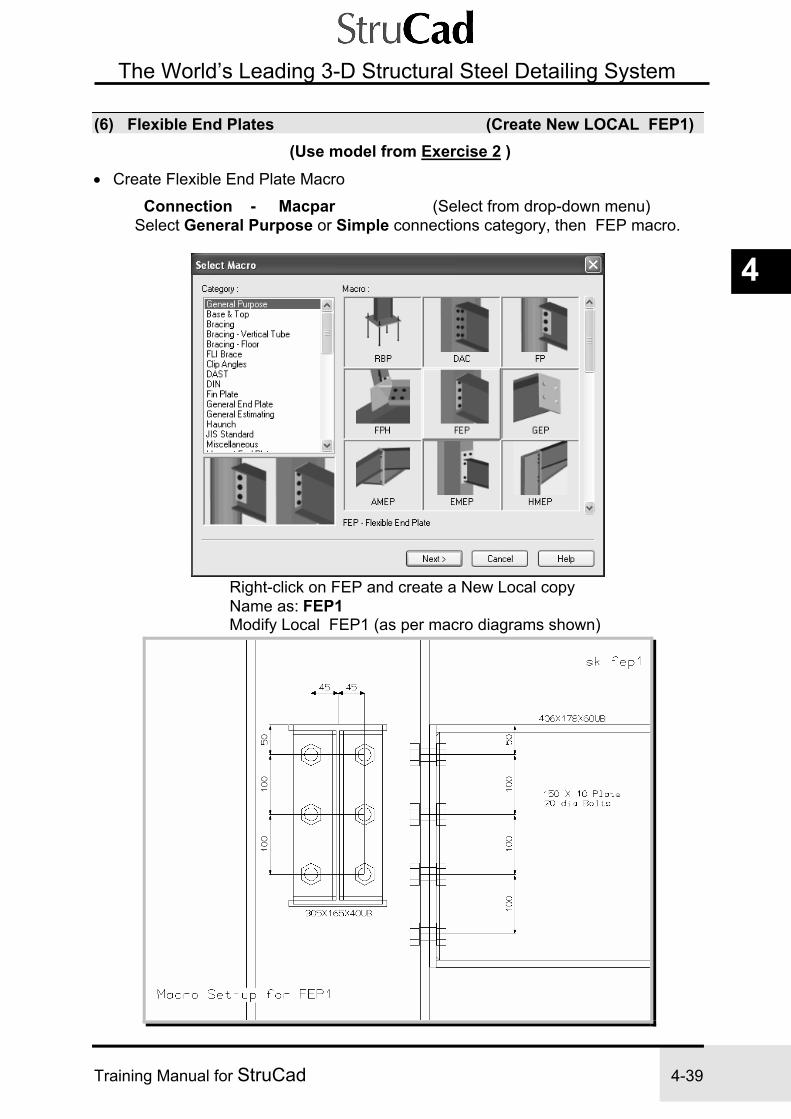
Exercise 4 StruCad Macro Connections
Training Manual for StruCad 4-39
4
The World’s Leading 3-D Structural Steel Detailing System
(6) Flexible End Plates (Create New LOCAL FEP1) (Use model from Exercise 2 )
• Create Flexible End Plate Macro
Connection - Macpar (Select from drop-down menu) Select General Purpose or Simple connections category, then FEP macro.
Right-click on FEP and create a New Local copy Name as: FEP1 Modify Local FEP1 (as per macro diagrams shown)

4-40 Training Manual for StruCad
FEP Macro Options Connection options; - Beam to Column or Beam to Beam. We will use the Beam to Column option. Plate Length options; - Full Depth or Partial Depth. We will use the Full Depth option. Range Tables Range tables may be used to enable macros to create variable connections, based on the depth and width of the section profile to which those macros are attached. In this macro we will look at the principle of range tables. Although additional ranges may be introduced, we will use the default ranges, which already exist in this macro. We will apply this macro to two different sizes of beam, being 305 x 165 x 40 UB and 406 x 178 x 60 UB You will see that the 305 beam is greater than 200mm deep, so it is too large for the first range, but is less than 380mm deep so it can be accepted by the second range. The 406 beam on the other hand, exceeds 380mm, but is less than 500mm deep, so it will fall into the third range. It is, therefore, these two ranges, the 380 and 500 ranges that we will edit for use on our beam connections.

Exercise 4 StruCad Macro Connections
Training Manual for StruCad 4-41
4
The World’s Leading 3-D Structural Steel Detailing System
Design Mode – No change
By editing the two range tables as shown we can achieve different connections, as shown on page 4-33, for two different sized beams.
Miscellaneous - No change Exit and Save:

4-42 Training Manual for StruCad
• Apply to Beam Ends
Endtype - (Select from the Icon Toolbar menu system) See Sketch sk 4.6 Select - Local Macros Select - Local FEP1 Select Member Ends as required
• Update and check, as for previous connections.

Exercise 4 StruCad Macro Connections
Training Manual for StruCad 4-43
4
The World’s Leading 3-D Structural Steel Detailing System
Repeat for FEP2 (Create New Local FEP2) • Create New Flexible End Plate Macro
Connection - Macpar Select Local Macro FEP1 Right-click FEP1 and create New Local copy Name as: FEP2 Modify Local FEP2
(as per macro diagram shown – All as FEP1 – (but with 16mm dia bolts)
N.B * FULL DEPTH/ AUTOMATIC/ 16mm DIA BOLTS/ 10mm plate/ 6mm welds
Exit and Save • Apply to Beam Ends
Endtype See Sketch sk 4.6 on page 4-42 Local Macros Select Local FEP2 Select Member Ends • Update and check, as for previous connections.

4-44 Training Manual for StruCad
(7) Eaves Tie General End Plate (Create New LOCAL GEP1) (Use model from Exercise 3)
• Create General End Plate Macro See Set-up File GEP1.DAT
Connection - Macpar
Select General Purpose or General End Plate category and GEP macro.
Right-click GEP and create New Local copy Name as GEP1 Modify Local GEP1
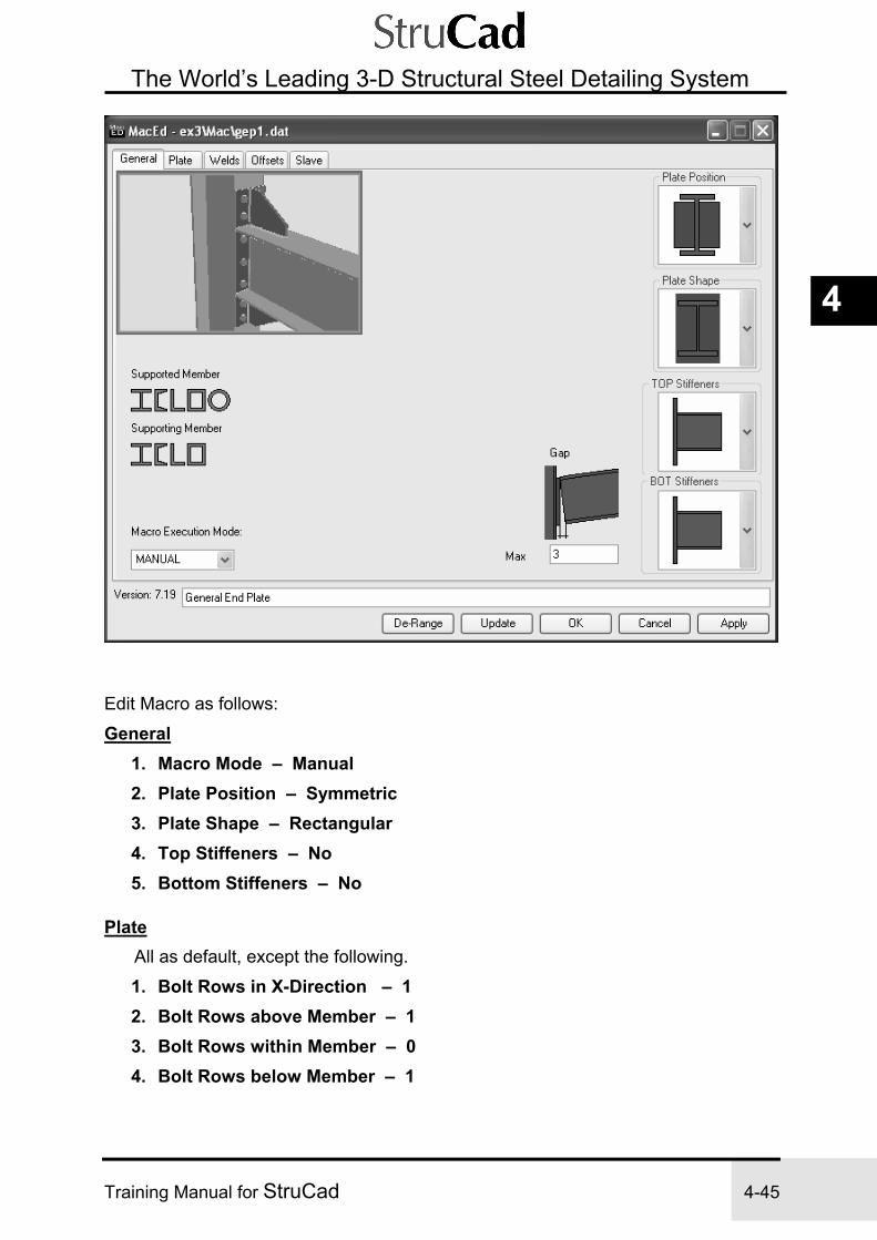
Exercise 4 StruCad Macro Connections
Training Manual for StruCad 4-45
4
The World’s Leading 3-D Structural Steel Detailing System
Edit Macro as follows:
General 1. Macro Mode – Manual 2. Plate Position – Symmetric 3. Plate Shape – Rectangular 4. Top Stiffeners – No 5. Bottom Stiffeners – No
Plate All as default, except the following.
1. Bolt Rows in X-Direction – 1 2. Bolt Rows above Member – 1 3. Bolt Rows within Member – 0 4. Bolt Rows below Member – 1

4-46 Training Manual for StruCad
Welds - No change Offsets - No change Slave - No change Exit and Save:

Exercise 4 StruCad Macro Connections
Training Manual for StruCad 4-47
4
The World’s Leading 3-D Structural Steel Detailing System
• Apply to Tie Beam Ends See Sketch sk 4.8
Endtype - (Select from the Icon Toolbar menu system) Select - Local Macros Select - Local GEP1 Select All Tie Beam Member Ends
• Update and use Loadjoint to View You will notice that the Eaves Ties are out of position. The next exercise shows
you how to reposition the Eaves Ties correctly using the interactive environment as a tool.
UPDATE & Check

4-48 Training Manual for StruCad
(8) Check for Clashes of Steelwork
In order to check the structure we have been detailing for collisions we must run the clash detection program. This will perform a check for clashes and bolt access problems etc. CLAsh - (Select from the Icon Toolbar menu system) Select the CLAsh command and when the option window appears, select the categories of clashes you want to check for by editing the yes/no boxes.
The tolerance default of 1mm should be kept.
Now decide whether you want to clash the whole model, choose ALL, or only part of the model, choose SELECT.
NOTE, if you choose to clash only part of the model you will be asked later to select those members which you want to check.
For our exercise we will choose ALL. Upon selecting accept to the above a clash report will be produced and this will summarise any clashes found. Press ok to continue and any clashes will be highlighted as Symbols in the 3-D model. Clash Symbol Explanation C – Hard clash in a joint (cleat to plate, bolt to fitting, fitting to member etc). B – Bolt access violations (Working area around bolt heads). M – Member to Member clash (Any clashes between members). F – Flying Fittings (Any fitting placed 1mmn or more from the member it is shopped to).

Exercise 4 StruCad Macro Connections
Training Manual for StruCad 4-49
4
The World’s Leading 3-D Structural Steel Detailing System
You will note that as default the clash symbols are displayed at the joint where the clash occurs with the exception of member clashes, where the symbol is positioned at the actual point in the wireframe where the two steels foul each other. You may toggle the location at which the other clash symbols are displayed between the standard join location and the actual clash location by depressing the ClaTOG icon. Further clash related options are available for selection.
Command Function Clash Off This will allow individual clash symbols to be disabled. Disabled clash
symbols will not be shown. Clash On Allows you to redisplay clash symbols you previously disabled with
ClaOFF. Clash information
Displays the clash information for the selected symbols on the StruCad pad.
Show Clashing Pieces
Highlights the wires or solids of those pieces involved in the clash that the selected symbol is representing. (must be working in solid mode)

4-50 Training Manual for StruCad
Turn off clashes –
CLAsh - HIClash - (Select from the Icon Toolbar menu system) Open the sub-menu to the CLAsh command by clicking on the ‘down arrow’ to the right of the icon and select the HIClash command.
Hiclash – Set all four clash categories to OFF - OR set ‘Delete all clash symbols’ to ON

Exercise 4 StruCad Macro Connections
Training Manual for StruCad 4-51
4
The World’s Leading 3-D Structural Steel Detailing System
(9) Produce Drawings
1. Produce some GA Drawings for the structure (as per end of Exercise 3): Plan on roof, foundation plan, typical section through building, elevations, etc.
2. Then produce some Material Lists (as per end of Exercise 2), including: Assembly List, All Members by Section, All Fittings by Section, Bolt Lists, Location Lists for Bolts (for hot and cold-rolled, shop and site bolts).
(11) Convert Drawings to DWG/DXF/DWF and PDF Formats
After creating drawings, open the drawings environment and select General Arrangements. (Note -The F2 function key from the wireframe is a direct link.)

4-52 Training Manual for StruCad
Open the General Arrangements folder and select the drawings you would like to convert by highlighting as shown. Place the cursor over one of the drawings in the selection and press the right mouse button to open the options table as shown, select Convert.
This will open the following selection table allowing you to convert these drawings to whichever format, and version of that format, you require.

Exercise 4 StruCad Macro Connections
Training Manual for StruCad 4-53
4
The World’s Leading 3-D Structural Steel Detailing System
(10) Labelling Drawings and Details using LABDEt
To add more information to a drawing or detail, open any drawing in the drawing environment and select the command LABDEt . If any command cannot be located on a toolbar, it may be typed from the keyboard. The letters shown in Upper Case throughout this manual are the minimum letters required to type each command.
Any entity on the drawing, members, fittings, bolts etc. may now be selected, and labelled as shown above.

4-54 Training Manual for StruCad
NOTES

Exercise 5 StruCad Interactive Eaves Ties
Training Manual for StruCad 5-1
5
The World’s Leading 3-D Structural Steel Detailing System
Exercise 5
INTERACTIVELY REPOSITION CHS EAVES TIE (Using model from Exercise 4)
The aim of this exercise is to manually re-work an eaves tie connection using the principles learnt and practised in Exercise 4.
SEQUENCE
(1) Determine Position of Eaves Tie (CHS) in Loadjnt
(2) Copy Graphics to New Position
(3) Measure
(4) Edit Members and Add Offsets
(5) Check the Model

Exercise 5 StruCad Interactive Eaves Ties
5-2 Training Manual for StruCad
The World’s Leading 3-D Structural Steel Detailing System
Exercise 5
INTERACTIVELY REPOSITION CHS EAVES TIE PROCEDURE
(1) Determine Position of Eaves Tie (CHS) sk 5.1 NOTE: The CHS Eaves Ties were inserted in Ex 3
• Load the Eaves Joint at A/1 (to take us into the Interactive Environment)
Position the mouse cursor over the eaves connection at A/1 and press the right-hand button.
LOADJnt (Select from object driven menu system)
• Clarify the Working View Manipulate the on-screen view, using the commands that you have already
learnt, to get the display below:
Layers Ports Wi, etc.

Exercise 5 StruCad Interactive Eaves Ties
Training Manual for StruCad 5-3
5
The World’s Leading 3-D Structural Steel Detailing System
(2) Copy Graphics to New Position sk 5.2 • Copy the End Plate parameters to New Position
Copy - (Select from the Interactive Icon Toolbar
menu system) Select the left hand side of
the End Plate Copy visually from Base Point to New Point (as sk 5.2) (Approx. 75mm in Y and -420mm in Z directions - (Global Vectors)) Visually ensure that the eaves tie end plate, when moved to its new position, will not clash with welds or the root radius of the column. To further ensure that there will be no clashes, you may wish to copy the bottom edge of the plate to the end of line to indicate the width of the end plate.

Exercise 5 StruCad Interactive Eaves Ties
5-4 Training Manual for StruCad
The World’s Leading 3-D Structural Steel Detailing System
(3) Measure sk 5.2 • Determine the Distance (to allow us to offset the wireframe member)
Query - Dist (Select from drop-down menu) 1st Point ..................... MID 2nd Point .................... MID
Note the Y, Z Components
• Exit from the Joint
Main - Unloadjnt
(4) Edit Members and Add Offsets sk 5.3 • Add Offsets to the Wire Frame
Modify - Edmem (Select from drop-down menu)
Select Members (Select All Eaves Ties as in sk 5.3) Local X Offset ........... Y Component Local Y Offset ........... -Z Component
NOTE: We can select the Eaves Ties on both sides of the building, because we have input them all anti-clockwise and therefore we have kept their local axes consistent.

Exercise 5 StruCad Interactive Eaves Ties
Training Manual for StruCad 5-5
5
The World’s Leading 3-D Structural Steel Detailing System
(5) Check the Model 1. Update the model (this will take the new offsets and apply them to the solid
model).
Modeller - Update (From drop-down menu) 2. Re-run the clash detection program, as in exercise 4, to check if everything is now OK.
Clash - (Select from the Icon Toolbar menu system) Turn off clash symbols on wireframe: -
Clash - Hiclash - (Select from the Icon Toolbar menu system) ----------------------------------------------------------------------------------------------------------------- NOTES

Exercise 5 StruCad Interactive Eaves Ties
5-6 Training Manual for StruCad
The World’s Leading 3-D Structural Steel Detailing System
NOTES

Exercise 6 StruCad Interactive Base Plate
Training Manual for StruCad 6-1
6
The World’s Leading 3-D Structural Steel Detailing System
Exercise 6
INTERACTIVE BASE PLATE (Using model from Exercise 5)
The aim of this exercise is to manually construct a special base plate, which has additional stiffeners.
SEQUENCE
(1) Select the Joint
(2) Add a Base Plate
(3) Add Bolts
(4) Add the Stiffener Plates
(5) Add Welds
(6) Shorten the Column
(7) Save Interactive Work using PUTLIB
(8) Exit from Interactive Environment
(9) Produce Drawings

Exercise 6 StruCad Interactive Base Plate
6-2 Training Manual for StruCad
The World’s Leading 3-D Structural Steel Detailing System
Exercise 6
INTERACTIVE BASE PLATE
PROCEDURE
(1) Select the Joint Move the mouse cursor over the joint at the bottom of the column on grid line A1 and press the right-hand button on the mouse. From the object menu, select the LOADJNT command
LOADJnt (Select from the object driven menu) This will take you straight into the interactive joint of the column base As there is only one member in this connection, it is automatically selected as
the current member, i.e. the member we want to work on.
Move the mouse cursor over the member and press the right-hand mouse button. An object - driven menu will appear with the main interactive commands available for the selected member:
Choose the Restore command.
This will remove the Base Plate connection already assigned to the member end.

Exercise 6 StruCad Interactive Base Plate
Training Manual for StruCad 6-3
6
The World’s Leading 3-D Structural Steel Detailing System
(2) Add a Base Plate sk 6.1 Move the mouse cursor over the member and press the right-hand button. The object - driven menu with the interactive commands for the selected member will be displayed again. Choose the PLATE command. This will create a new plate defined from a face of the column. You are first asked to select which face of the column you intend to connect the plate to.
Choose the END face.
Accept ......... YES

Exercise 6 StruCad Interactive Base Plate
6-4 Training Manual for StruCad
The World’s Leading 3-D Structural Steel Detailing System
Select Shape ......... RECT
Use ‘arrow heads’ right and left to open and close plate ‘help shape’

Exercise 6 StruCad Interactive Base Plate
Training Manual for StruCad 6-5
6
The World’s Leading 3-D Structural Steel Detailing System
• Plate Parameters Edit plate parameters as shown, ignore plate name and group name. Select face of plate to connect to column end:
Select FRONT face and accept. Then select No Rotation from the dialog box that appears - we don’t need to rotate the plate.
NOTE: You can only rotate around the Z-axis. Position the plate by inputting the following coordinates: Base Point .......... RETURN (TO ACCEPT 0,0,0) New Point .......... RELATIVE
(From Current Position) X = 200, Y = -325 Accept .......... YES

Exercise 6 StruCad Interactive Base Plate
6-6 Training Manual for StruCad
The World’s Leading 3-D Structural Steel Detailing System
HINT:
If, at any stage of applying a plate, you do something wrong, do not CANCEL (or Escape). Instead, when the command asks you to CONFIRM the action, say NO - you will then be allowed another attempt. If you cancel the activity, you will have to start from the beginning of the command again!! This also applies when you are creating cleats and bolts.

Exercise 6 StruCad Interactive Base Plate
Training Manual for StruCad 6-7
6
The World’s Leading 3-D Structural Steel Detailing System
(3) Add Bolts sk 6.2 Move the mouse cursor over the new end plate and press the right-hand button. This will give you a menu of commands that can be applied to the plate.
Select the BOLTS command from the dialog box. This will enable you to insert bolts into the plate. (If, on the other hand, we wished to place bolts or holes in the column itself, then the mouse would be clicked over the column.) Select Face on Plate........…..FRONT (Face to drill bolts through.)
Accept ……… Yes

Exercise 6 StruCad Interactive Base Plate
6-8 Training Manual for StruCad
The World’s Leading 3-D Structural Steel Detailing System
Input parameters of bolts Bolt Parameters (select default, unless noted otherwise) No. in X .......... 2
Pitch in X ......... 300 No. in Y .......... 2 Pitch in Y .......... 550 Bolt Diameter .......... 20 Hole Diameter. ……...24 Bolt Grade .......... 8.8 Bolt Type ......... SQSQOX Holding Down Bolt Spec .......... HD450
(A Holding Down Bolt 450mm long. This is read from the file ‘hdbolts.dat’ in the data directory in your model) Ignore Number of Plies and Hole Type. Accept
Then input the position of bolts (type in from keyboard) Bolt Origin .......... 50,50 Position of reference bolt for the group (of 4) from the UDS of the front face of the plate Accept ……… Yes
(The bolt parameters use the X-Y axis of the face of the plate you select)

Exercise 6 StruCad Interactive Base Plate
Training Manual for StruCad 6-9
6
The World’s Leading 3-D Structural Steel Detailing System
NOTE: The bolts shown here are graphical representations of the extended Holding Down Bolts. They are shown fully if they are displayed in the wire / solid environment using the DISPLAY command. However, they will not be drawn extended like this in the drawings, nor in hidden-line views, since the Drawing Production system (DPS) can only draw them in their short form.

Exercise 6 StruCad Interactive Base Plate
6-10 Training Manual for StruCad
The World’s Leading 3-D Structural Steel Detailing System
Positioning of Bolts Relative to the UDS of the Chosen Face of the Plate When defining bolts on a plate (or a member), you will give them a positive pitch in the X and Y directions. If for example a set of 4 bolts are defined (2 in X, 2 in Y). One bolt from the group is considered the referance bolt, with the others in the group being positioned in relation to it. The referance bolt is poisitioned as default on origin point (position of the axis), the additional bolts are then placed as per the figures input in the bolt parameters, so the second bolt in X and Y will be at the specified distance in the positive direction. The axis’ direction will differ depandant upon the plate type selcted the initial face chosen to drill through, in turn the bolts may not be positioned as desired, should this be the case then the pos in X and Pos in Y options available in the bolt parameters should be toggled. As default the “Near” option is selceted, “centre” and “far” are also available. In the example situation the pos in X should be changed to far, this will alter the position of the furthest bolt from reference bolt to the origin point. The centre option will take the midpoint of the reference bolt and the furthest bolt and place that position on the origin point.

Exercise 6 StruCad Interactive Base Plate
Training Manual for StruCad 6-11
6
The World’s Leading 3-D Structural Steel Detailing System
(4) Add the Stiffener Plates sk 6.3 Move the mouse cursor over the member and press the right-hand button on the mouse. The member’s object menu appears with the appropriate interactive commands. Choose the PLATE command. This will create a new plate defined from a face of the column. You are now asked to select which face of the column you intend to connect the plate to.
Choose the BOTL face:
Accept ......... YES

Exercise 6 StruCad Interactive Base Plate
6-12 Training Manual for StruCad
The World’s Leading 3-D Structural Steel Detailing System
Select Shape from Poly-Stiffeners ........……….STIFF2
Use ‘arrow heads’ right and left to open and close plate ‘help shape’

Exercise 6 StruCad Interactive Base Plate
Training Manual for StruCad 6-13
6
The World’s Leading 3-D Structural Steel Detailing System
Plate Parameters (select default, unless otherwise noted) Thk ......... 10 B ......... 200 D ......... 650 CB ......... 70 CD ......... 70 Face of Plate to Connect .......... BACK Confirm .......... YES No Rotation Base Point .......... END/INT in sk 6.3
To clarify your view of these points, in the isometric viewport, press right-hand button to get Snap Mode menu and use WI command for clarity.
New Point .......... INT

Exercise 6 StruCad Interactive Base Plate
6-14 Training Manual for StruCad
The World’s Leading 3-D Structural Steel Detailing System
• Copy Second Plate See sk 6.4 Move mouse cursor over new plate and press the right-hand button on the mouse. The plate’s object – driven menu will appear.
Choose the Scopy command (Solid Copy, and then use the plan viewport only).
NOTE: In the activity below you will be using SINT and LINT, two SNAPS that treat the 3D environment, in which we are working, as if it were a 2D environment. These two SNAPS will ONLY work correctly in the Plan View, Right View and the Front View, and NOT in the Isometric View. All the other available SNAPS work in ALL the viewports as 3D areas. Using SCOPY we will be copying the plate (whereas, if we had wanted to copy the bolts, then we would have clicked the mouse cursor on the bolts). Select Plate ......... Select any line of the Plate Base Point ......... LINT (Select Lines 1 & 2, sk6.4) (LINT is a Line Intersection, where two lines that don’t meet would
intersect. Press right-hand button to get SNAPS from which to select LINT and SINT.)
New Point ........ SINT (Screen Intersection) No. of Copies ........ 1
SINT and LINT Rules
There are three rules you must obey when using SINT and LINT: 1) Only use SINT and LINT in the PLAN, RIGHT and FRONT viewports, and NOT in
an Isometric Port. 2) Only use SINT and LINT in one viewport - DO NOT go across viewports. 3) Only use SINT and LINT together in the same command. DO NOT use SINT to
END or END to SINT, as they will not work as you expect them to.

Exercise 6 StruCad Interactive Base Plate
Training Manual for StruCad 6-15
6
The World’s Leading 3-D Structural Steel Detailing System
(5) Add Welds sk 6.5 • Clarify Working View Work in the isometric viewport, as you will find it easier to select the points to weld. Once you start work on the weld, you may want to turn off
some layers (use LAYOFF from drop-down menu), or individual items (use UNDISPLAY, Select Solid), to clear your view of the welding area.
Move the mouse cursor over the member and press the right-hand button. The object – driven menu will appear, with the interactive commands for the selected member:
Choose the WELD command. This will create a weld defined from a face of the column You will then be asked which face of the column to fix the weld to. Face / All Round……………FACE Parent Face ..……………….END Accept ….…………………..YES

Exercise 6 StruCad Interactive Base Plate
6-16 Training Manual for StruCad
The World’s Leading 3-D Structural Steel Detailing System
Set up the weld parameters:
Start Point ......... Select Point Offset Dist ......... 0 End Point ......... Select Point Offset Dist ......... 0 Confirm ......… YES
NOTE: The weld is defined by the direction of the arrows on the member.
• Repeat on other Flange, selecting its Points and
• Repeat for Web Weld, Points and , with the differences being: Weld Parameters SINGLE / DOUBLE should read DOUBLE (i.e. both sides of web) 1st Offset should be 100 2nd Offset should be -100

Exercise 6 StruCad Interactive Base Plate
Training Manual for StruCad 6-17
6
The World’s Leading 3-D Structural Steel Detailing System
Weld Parameters
Some of the weld parameters are obvious, but the ones that aren’t are as follows:
Round/Segment ............ Weld either all round the chosen face, or weld part of the chosen face (e.g. a Segment).
Shop/Field ..................... A shop weld or a site (field) weld
Spec. of Weld ............... FSE42 means a fillet weld in the shop using Electrode Strength 42
Inside/Outside ................ Weld either inside or outside the line of the face chosen to weld.
Single/Double ................. Either a single weld between the two points you choose or a double weld. The latter will give you a weld between the points you choose and, in addition, a weld on the corresponding opposite face, i.e. welds on both sides of a web.
Stitch Weld ..................... Do you require a stitch weld? (If you say YES, it will prompt you for the number of stitches and the spacing between them. Then define the length of weld - you pick the start point, and for the end point of the weld you pick the same point again. Then specify an offset equal to the weld run length required.)

Exercise 6 StruCad Interactive Base Plate
6-18 Training Manual for StruCad
The World’s Leading 3-D Structural Steel Detailing System
Weld Parameters (Continued)
This time we have chosen the weld “Parent” as a fitting, which means that we define it off one of the faces of the plate. Once we have chosen the plate face (in this case the front or the back), we can apply a segment weld. But this time it will be ‘Inside’ the weld line (i.e. in the plate). If we had chosen to weld outside the line, the weld would have been on the inside of the flanges and the web of the member.

Exercise 6 StruCad Interactive Base Plate
Training Manual for StruCad 6-19
6
The World’s Leading 3-D Structural Steel Detailing System
(6) Shorten the Column • Shorten Column (by thickness of Base Plate)
The wireframe column is drawn from the USBP (Underside of Base Plate) level and so we must shorten the column by the thickness of the base plate.
Move the mouse cursor over the member and Press the right-hand button to get the member’s menu of interactive commands:
Choose the SHORTEN command.
Shorten by Distance ……… 20

Exercise 6 StruCad Interactive Base Plate
6-20 Training Manual for StruCad
The World’s Leading 3-D Structural Steel Detailing System
(7) Save Interactive Work using PUTLIB Move the mouse cursor over the member and press the right-hand button. From the member’s menu of interactive commands choose the PUTLIB command:
Set up the Putlib dialog box as described below
NOTE: It is important to get into the routine of saving your “putlibs” using a system that relates to the contract, and is in numerical order. The description is also important, as it allows you to recognise the “putlibs” at a later date when you list them using LISTLIB.
Library Name ……………...ex6-001 (i.e. the first file created on Contract ex6) Initials …….....………..……..(Type your initials) Description .....……….……..Stiffened Base Plate to suit 457X191 UB Apply Current....………….....Yes Save Global.......…………….No (just save a local copy) Add or Remove Objects ...…No (Only use if not saving all objects in joint) All Objects .......……………..All (everything defined from the Current Member end) Member end actions .………Yes (All shortens, rotations, intersects etc on member)
Select ‘OK’ to create Putlib and save connection.

Exercise 6 StruCad Interactive Base Plate
Training Manual for StruCad 6-21
6
The World’s Leading 3-D Structural Steel Detailing System
(8) Exit from Interactive Environment Main - Unloadjnt (Select from drop-down menu) StruCad will detect that you have done a PUTLIB and will exit from the joint
without re-saving it.
If, however, you forgot to do a PUTLIB, it will remind you to:
Confirm to do a PUTLIB .................. YES
If you have NOT saved the member end as a putlib, then UNLOADJNT and select NO, this will result in a loss of all the work that you have done in this interactive session.
(9) Produce Drawings 1. UPDATE the model if it did not automatically update itself when you unloaded the joint (a CADMODES setting controls this). 2. Produce fabrication drawings of the member with the interactive base plate and check that it is OK. (The HD bolts are not shown at all.)
EXIT Save Changes

Exercise 6 StruCad Interactive Base Plate
6-22 Training Manual for StruCad
The World’s Leading 3-D Structural Steel Detailing System
NOTES

Exercise 7 StruCad Interactive Connection
Training Manual for StruCad 7-1
7
The World’s Leading 3-D Structural Steel Detailing System
Exercise 7
CONNECTION TO TOES OF SUPPORTING BEAM (Using model from Exercise 2)
This exercise gives more practice in producing customised connections interactively. This connection will join two horizontal beams as shown below.
SEQUENCE
(1) Open Model from Exercise 2
(2) Input Members and Update
(3) Select Joint
(4) Select the Current Member
(5) Shorten the Member

Exercise 7 StruCad Interactive Connection
7-2 Training Manual for StruCad
The World’s Leading 3-D Structural Steel Detailing System
(6) Add End Plate
(7) Add a Second Plate across the Toes
(8) Edit Plate across the Toes of Supporting Beam
(9) Move Plate into Position
(10) Add Top Flange Stiffener
(11) Add Web Stiffener
(12) Add Bolts
(13) Check Plate Ownership
(14) Save the Interactive Work
(15) Exit from the Interactive Environment
(16) Update and Produce Drawings
(17) Add More Secondary Members
(18) Enable Joints to Act Together

Exercise 7 StruCad Interactive Connection
Training Manual for StruCad 7-3
7
The World’s Leading 3-D Structural Steel Detailing System
Exercise 7
CONNECTION TO TOES OF SUPPORTING BEAM PROCEDURE
(1) Open Model from Exercise 2 Rationalise the view as shown in sk 7.1 below. Set Layer to First Floor and switch off Layer for Second Floor
(2) Input Members and Update sk 7.1 MEMber
Add a beam at mid-bay, with Local Y offset (Y off) as shown in sk 7.1 below.
UPdate Update the model.

Exercise 7 StruCad Interactive Connection
7-4 Training Manual for StruCad
The World’s Leading 3-D Structural Steel Detailing System
(3) Select Joint Move the mouse cursor over the joint where the new mid-bay member touches the member on Grid Line D and press the right-hand button on the mouse.
LOADJnt (Select from object driven menu) This will load the joint where the two beams touch.
(4) Select the Current Member Select the non-continuous member (i.e. the new member)
(5) Shorten the Member • First work out the distances to shorten by.
Right-click the mouse in the bottom right area of the screen. The floating menu shown below will appear:
Select - Dist
Measure from Point to Point in sk 7.2 Note the Y component (i.e. 82.50)

Exercise 7 StruCad Interactive Connection
Training Manual for StruCad 7-5
7
The World’s Leading 3-D Structural Steel Detailing System
• Now Shorten the member Move the mouse cursor over the member and press the right-hand
button on the mouse. The menu of interactive commands available for the selected member will appear:
Choose the SHORTEN command. This will shorten the current end.
Choose Shorten by Distance Enter 107.5 (i.e. 82.5mm +25mm for 2 x 12mm plates and 1mm erection clearance)
• Measure Dimension for Plate across Toes of Supporting Beam
Interactive Utils - Dist (Right click in bottom right for floating menu)
From Point to Point in sk 7.3 (This distance is to determine the length of the plate required across the toes of the supporting member)
Note the Z component (i.e. 403.4) (A distance of 400 will be used later)

Exercise 7 StruCad Interactive Connection
7-6 Training Manual for StruCad
The World’s Leading 3-D Structural Steel Detailing System
(6) Add End Plate sk 7.4 Click the right-hand button on the mouse over the member to get the object–driven menu of interactive commands for the selected member.
Choose the PLATE command. This will create a new plate defined from a face of the column. You are then asked to select the face of the column you are to connect the plate to:
Choose the END face.
Accept ......... YES

Exercise 7 StruCad Interactive Connection
Training Manual for StruCad 7-7
7
The World’s Leading 3-D Structural Steel Detailing System
You are then asked to select the shape of the plate:
Select Shape ......... RECT Now set up the plate parameters as you did in Exercise 6: Plate Parameters (select default, unless noted otherwise) Thickness .......... 12 B .......... 150 D .......... 250 Face of Plate to Connect.... FRONT Confirm .......... YES No Rotation Measure .......... Distance (Top of plate to top of beam) Base Point .......... RETURN (i.e. 0,0,0) New Point .......... 75, -124.3 (i.e. distance measured above) (To keep the plate flush with the top flange) Confirm .......... YES

Exercise 7 StruCad Interactive Connection
7-8 Training Manual for StruCad
The World’s Leading 3-D Structural Steel Detailing System
(7) Add a Second Plate across the Toes Right-click the mouse cursor over the new plate and an object-driven menu of interactive commands, applicable to the selected plate, will appear:
Choose the Scopy command
(Solid Copy - this enables us to copy the plate) Base Point ........... INT New Point ........... REF/INT Z=1 (1mm clearance) Number of Copies ........... 1
(8) Edit Plate across the Toes of Supporting Beam Open the object-driven menu of interactive commands, as above, for this newly copied plate. Choose the EDPLATE command (This enables us to edit the parameters of the selected plate):

Exercise 7 StruCad Interactive Connection
Training Manual for StruCad 7-9
7
The World’s Leading 3-D Structural Steel Detailing System
Edit new plate as follows;-
Plate Ownership........... SHOP ANOTHER D (plate depth) ........... 400 (i.e. approx. 403.8) Select Member ..…... Select Continuous Member
We use Shop Another because we are creating the plate from the current member, but we actually want the plate to be shown on another member’s shop detail (the supporting member), and not on the current member.
(9) Move Plate into Position Right-click mouse over second plate for the interactive plate commands.
Choose the Smove command (use Solid Move to move the plate) Base Point ........... RETURN (0,0,0) New Point ........... REL Y= -150
(10) Add Top Flange Stiffener • First measure the size that the stiffener plate will be. Right-click the mouse in the bottom right area of the screen. The Interactive Utilities floating menu appears:
Choose the DIST command
Measure the Distance From Point to Point in sk 7.5 Note the Y & Z components

Exercise 7 StruCad Interactive Connection
7-10 Training Manual for StruCad
The World’s Leading 3-D Structural Steel Detailing System
• Create Stiffener Plate Right-click mouse on the current member to get the Interactive Member menu again
Choose the Plate command (to create the new plate)
Select Face of Beam....…....….. END Accept …......……………….... …YES Select Shape..………………….. TRIANG (from the Tri-Stiffeners section)
Plate Parameters as shown above
Use ‘arrow heads’ right and left to open and close plate ‘help shape’

Exercise 7 StruCad Interactive Connection
Training Manual for StruCad 7-11
7
The World’s Leading 3-D Structural Steel Detailing System
Select Member ......…..... Select continuous member
Face of Plate to Connect ...…..... BOT Confirm ……............ …………….YES
Rotate by Angle .........……………180
Base Point ........…………………...MID in sk 7.6 New Point.........…………………….MID Confirm ........... ……………………YES
Alternatively, the stiffener plate may be created from the Continuous Member. Right-click mouse on the continuous member to get the Interactive Member menu,
Choose the Plate command
Select Face of Beam....…....…... TOP Accept …......……………….... .…YES
Create plate, all as above, except Plate Ownership will be Shop Current. Face of Plate to Connect ...…..... LEFT Confirm ……............ …………….YES
No Rotation
Base Point ........……………. RETURN (0,0,0) see sk 7.6a New Point.........………………REL ‘X’ = 5 (to move the plate by half its thickness) Confirm ...........…………….…YES

Exercise 7 StruCad Interactive Connection
7-12 Training Manual for StruCad
The World’s Leading 3-D Structural Steel Detailing System
(11) Add Web Stiffener sk 7.7 • Measure Size for Web Stiffener
INTERACTIVE Utils - Dist (Select from bottom right floating menu) From point 11 to point 12 in sk 7.7 (To determine stiffener plate dimensions) Note the Y & Z components

Exercise 7 StruCad Interactive Connection
Training Manual for StruCad 7-13
7
The World’s Leading 3-D Structural Steel Detailing System
• Create Stiffener Plate See sk 7.8 Right-click mouse over the raised member to get the Interactive Member Commands menu. Choose the Plate command.
Select face of Beam ........... END Confirm ........... YES Select Shape ........... STIFF2
Plate Parameters (select default, unless noted otherwise)
Thickness ........... 10 Plate Ownership ........... SHOP ANOTHER B ........... 79 D ........... 282 CB ........... 10 CD ........... 10
Select Member ........... Select Continuous Member
Face of Plate to connect ........... BOT Confirm ........... YES No Rotation
Measure .......... Distance (Mid to Mid ) Base Point ........... RETURN (i.e. 0,0,0) New Point ........... REL 5, -267, 25
X = 5 (1/2 plate thickness), Y = -267 (Measured distance
from Mid to Mid as above) Z = 25 (2 plates +1mm clearance)

Exercise 7 StruCad Interactive Connection
7-14 Training Manual for StruCad
The World’s Leading 3-D Structural Steel Detailing System
Alternatively, as with the triangular stiffener, this plate may also be created from the Continuous Member.
Right-click mouse on the continuous member to get the Interactive Member menu,
Choose the Plate command Select Face of Beam....…....…... WEBL Accept …......……………….... .…YES
Create plate, all as above, except Plate Ownership will be Shop Current. Face of Plate to Connect ...…..... TOP Confirm ……............ …………….YES No Rotation
Base Point ........…………. RETURN (0,0,0) see sk 7.8a New Point.........……………REL ‘X’ = 5 (to move the plate by half its thickness) ‘Y’ = 10.5 (to move the plate by the depth of the ‘crop’ + 0.5mm clearance) Confirm ...........………….…YES

Exercise 7 StruCad Interactive Connection
Training Manual for StruCad 7-15
7
The World’s Leading 3-D Structural Steel Detailing System
(12) Add Bolts SK 7.9 Right-click the mouse over the end plate of the smaller UB to get the menu of interactive commands applicable to that plate.
Choose the Bolts command. Select face of plate ....... FRONT (so that bolts drill through both plates) Accept .......... YES (UDS icon on plate) Bolt Parameters (use defaults, unless noted otherwise)
Number in X .........……… 2 (note X-Y axis direction Pitch in X ………….......... 90 on screen) Number in Y .........………..2 Pitch in Y…............. ……...150 Accept rest of defaults Enter Bolt Origin ........... 30,50 (type in from keyboard) Accept ........... YES (Ignore Number of Plies and Hole Type - we will use the defaults)

Exercise 7 StruCad Interactive Connection
7-16 Training Manual for StruCad
The World’s Leading 3-D Structural Steel Detailing System
(13) Check Plate Ownership INTERACTIVE Utils - Hifit (Select from bottom right floating menu)
NOTE Shop Current - Will highlight fittings which are shopped to the current member.
Shop Another - Will highlight fittings which are shopped to a member which is not the current member.
Select the Current Member
Select - Shop Current - This should now only highlight the current member and the small end plate which is shopped to the current member.
Accept? - NO (thus allowing us to select another option after viewing our Shop Current selection)
Select - Shop Another - Select Continuous Member This should now highlight the continuous member together with the plate across the toes, the compression stiffener and the triangular stiffener and which are all shopped to the continuous member. Accept? - YES (to exit command)
NOTE: Although the plates are all defined off the current member end, the ownership of the two stiffeners and the toe plate was shop another. This means that they will appear on the shop detail of the continuous member you selected to shop them to. However, the plates that are highlighted as shop another to the continuous beam are not defined off that member. This becomes important when you save your interactive connection as a “Putlib”. When you run Putlib, the items saved are everything defined off the current member, including items shopped to another member. In this case, everything is included in the one Putlib.
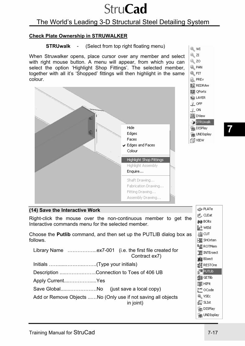
Exercise 7 StruCad Interactive Connection
Training Manual for StruCad 7-17
7
The World’s Leading 3-D Structural Steel Detailing System
Check Plate Ownership in STRUWALKER
STRUwalk - (Select from top right floating menu)
When Struwalker opens, place cursor over any member and select with right mouse button. A menu will appear, from which you can select the option ‘Highlight Shop Fittings’. The selected member, together with all it’s ‘Shopped’ fittings will then highlight in the same colour.
(14) Save the Interactive Work Right-click the mouse over the non-continuous member to get the Interactive commands menu for the selected member.
Choose the Putlib command, and then set up the PUTLIB dialog box as follows.
Library Name ……………...ex7-001 (i.e. the first file created for Contract ex7) Initials …….....………..……..(Type your initials) Description .....……….……..Connection to Toes of 406 UB Apply Current....………….....Yes Save Global.......…………….No (just save a local copy) Add or Remove Objects ...…No (Only use if not saving all objects in joint)

Exercise 7 StruCad Interactive Connection
7-18 Training Manual for StruCad
The World’s Leading 3-D Structural Steel Detailing System
All Objects .......……………..All (everything defined from the Current Member end) Member end actions .………Yes (All shortens, rotations, intersects etc on member)
Select ‘OK’ to create Putlib and save connection.
(15) Exit from the Interactive Environment Main - Unloadjnt (Select from drop-down menu) No confirmation is necessary since you have just created a PUTLIB.
(16) Update and Produce Drawings 1. UPDATE the model if it did not update automatically when you unloaded the joint. 2. Produce shop drawings (fabrication drawings) of both the raised member and the supporting continuous members. Check that the plates are shopped to the correct members.

Exercise 7 StruCad Interactive Connection
Training Manual for StruCad 7-19
7
The World’s Leading 3-D Structural Steel Detailing System
(17) Add More Secondary Members sk 7.10 MEMber - (Select from the Icon Toolbar menu system)
Edit the Member Attributes dialog box to show the correct Stock Size, and add members to model. Stock Size ............... 203x133x25UB Insert members ‘A’ and ‘B’ in sk 7.10
Start Point ............. REF, INT, X = -1600 to position Point End Point ............. REF, INT, Y = -1600 to position Point Start Point ............. REF, INT, X = -1600 to position Point End Point ............. REF, INT, Y = 1600 to position Point

Exercise 7 StruCad Interactive Connection
7-20 Training Manual for StruCad
The World’s Leading 3-D Structural Steel Detailing System
• Modify Flexible End Plate Macro
Open Macro FEP2 (created in Ex4) Edit page ‘Bolted to Column’ Open both Range Tables and insert a new range of ‘220’, and edit both as shown below.
• Apply to Trimmer Steel
Endtype - (Select from the Icon Toolbar menu system)
Select - Local Macros Select - FEP2 Apply to both ends of diagonal trimming steel on both sides of grid line 4.
Update model.
When each of the four joints along grid line 4 are now loaded, they will all appear to be ok, but, as there is only 100mm between each pair of connections, it is clear that these joints will interfere with each other. The following StruWalker view shows this quite clearly.

Exercise 7 StruCad Interactive Connection
Training Manual for StruCad 7-21
7
The World’s Leading 3-D Structural Steel Detailing System
This interference may be rectified by allowing the two joints to act together.
(18) Enable Joints to Act Together Option 1 - Use the ‘ENDAdjst’ command.
The ENDAdjst command is used to change a member’s end position in the wireframe, whilst retaining the same physical position of the steel. The adjustment is achieved by automatically adjusting the global offsets according to the new end coordinates. (In respect of the wireframe and the true steel position, this command does the exact opposite of the ECCent command.) Moving a joint to the same location as another, without moving the steel, will allow coherent Macro and Interactive connections to be created.
ENDAdjst - (Select from the Icon Toolbar menu system)
With the ENDAdjst command loaded, select member ‘A’ towards end ‘1’ (see sk 7.11), and, with snaps set to ‘intersection’ select point ‘2’. The ‘Wire’ will move to the new joint, but the steel will remain in the same position.

Exercise 7 StruCad Interactive Connection
7-22 Training Manual for StruCad
The World’s Leading 3-D Structural Steel Detailing System
Update the model and load the joint. You will now see that the macro has adjusted the end connections so that they work together.
Option 2 - Use the ‘LINK’ command. The LINK Command may be used where it is not desirable, or practical, to change the position of the wires.
The LINK command is used to link together two or more joints into one Master joint of the wireframe, enabling all linked joints to be viewed and/or worked on when the Master joint is loaded.
LINK - (Select from the Icon Toolbar menu system)
From the sub-menu of the ENDAdjst command, find the LINK command
When linking joints together, the first joint to be selected will be the Subordinate joint; select joint 3. sk 7.12 The next joint to be selected will be the Master joint; select joint 4. sk 7.12 This will create a link between the joints, which you will see represented in the wire frame. sk 7.13

Exercise 7 StruCad Interactive Connection
Training Manual for StruCad 7-23
7
The World’s Leading 3-D Structural Steel Detailing System
Now Update the model and load joint 4. You will see joints, 3 and 4, together, which shows the macro has combined the two connections.
Save and Exit

Exercise 7 StruCad Interactive Connection
7-24 Training Manual for StruCad
The World’s Leading 3-D Structural Steel Detailing System
NOTES

Exercise 8 StruCad Modify Portal Frame
Training Manual for StruCad 8-1
8
The World’s Leading 3-D Structural Steel Detailing System
Exercise 8
PORTAL FRAME INCLUDING LATTICE AND HIPS (Using model from Exercise 6)
In this exercise we will add Hip Rafters and a Lattice Truss Assembly to the Portal Frame Structure from an earlier exercise..
SEQUENCE (1) Create WCAD of Model from Previous Exercise
(2) Switch to New Model
(3) Erase Redundant Members
(4) Add Hip Rafters
(5) Trim Purlins to Hip and Portal Rafters
(6) Add Lattice Members
(7) Define Members together to Create an Assembly
(8) Apply a Camber to Lattice
(9) Apply End Connections and Update
(10) Produce Drawing of Lattice Assembly

Exercise 8 StruCad Modify Portal Frame
8-2 Training Manual for StruCad
The World’s Leading 3-D Structural Steel Detailing System
(11) Modify Portal Legs and weld to Columns
(12) Create Assemblies of Portal Legs and Columns
(13) Add Haunched Moment Connections to Portal Beam
(14) Create Gable Post to Rafter Connections
(15) Changing the View in the Model Environment
(16) Checking Fitting Ownership in the Model Environment

Exercise 8 StruCad Modify Portal Frame
Training Manual for StruCad 8-3
8
The World’s Leading 3-D Structural Steel Detailing System
Exercise 8
PORTAL FRAME INCLUDING LATTICE AND HIPS PROCEDURE
(1) Create WCAD of Model from Previous Exercise First enter your model from Exercise 6. We want to preserve this and make another model to modify here.
Utility - Export - WCAD (Select from drop-down menu)
Edit WCAD dialog box as below and select ‘Accept’.
The task bar will offer ‘Insertion Base Point <0.0,0.0,0.0>’ {press Enter to accept} This creates a copy of the model from Exercise 6 that we can access as a new model and modify, as we require.
(2) Exit Model and Enter New Model ex 8 Exit ........... Save the changes (although no changes have been made)
At the Workspace, enter the new model ex 8
(3) Erase Redundant Members Modify - Erase (Select from drop-down menu)
Select the rafters and the gable posts that are on Grid Line 1 and bracing members between Grid Lines 1 and 2
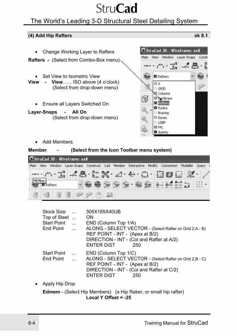
Exercise 8 StruCad Modify Portal Frame
8-4 Training Manual for StruCad
The World’s Leading 3-D Structural Steel Detailing System
(4) Add Hip Rafters sk 8.1
• Change Working Layer to Rafters
Rafters - (Select from Combo-Box menu)
• Set View to Isometric View View - View…... ISO above (4 o’clock) (Select from drop-down menu)
• Ensure all Layers Switched On
Layer-Snaps - All On (Select from drop-down menu)
• Add Members
Member - (Select from the Icon Toolbar menu system)
Stock Size ... 305X165X40UB Top of Steel ... ON Start Point ... END (Column Top 1/A) End Point ... ALONG - SELECT VECTOR - (Select Rafter on Grid 2,A - B) REF POINT - INT - (Apex at B/2) DIRECTION - INT - (Col and Rafter at A/2) ENTER DIST 250 Start Point ... END (Column Top 1/C) End Point ... ALONG - SELECT VECTOR - (Select Rafter on Grid 2,B - C) REF POINT - INT - (Apex at B/2) DIRECTION - INT - (Col and Rafter at C/2) ENTER DIST 250
• Apply Hip Drop Edmem - (Select Hip Members) (a Hip Raker, or small hip rafter) Local Y Offset = -25

Exercise 8 StruCad Modify Portal Frame
Training Manual for StruCad 8-5
8
The World’s Leading 3-D Structural Steel Detailing System
(5) Trim Purlins to Hip and Portal Rafters sk 8.2
TRIM - (Select from the Icon Toolbar menu system)
For the Edge to trim to, select the new hip rafter (Except see note) For members to trim, select purlins protruding outside the rafter. NOTE: The top purlin must be trimmed to the portal rafter - see SK 8.2.
• Create Hip Connection Macro
Macpar - (From the Icon Toolbar menu system) From General Purpose or Simple connection macros, select FPH (Fin Plate for Hips), then make a Local Copy, fph1. Now edit macro to produce either a welded plate connection, or, a bolted bracket connection as you wish.

Exercise 8 StruCad Modify Portal Frame
8-6 Training Manual for StruCad
The World’s Leading 3-D Structural Steel Detailing System
• Apply End Connections
Endtype - (Select from the Icon Toolbar menu system)
Select ‘Local Macros’ From Local Macros - Select fph1 Apply to all Purlin ends, which attach to the hip rafters.

Exercise 8 StruCad Modify Portal Frame
Training Manual for StruCad 8-7
8
The World’s Leading 3-D Structural Steel Detailing System
• Erase Redundant Members
ERase ... Select dummy purlin and top far-side purlin
• Create Hip Rafter Connections
MACPar
From General Purpose or Simple connection macros, select FP (Fin Plate), and then make a Local Copy, fp1 and alter the macro design mode to manual from the Design and Welds tab.
• Apply End Connections
ENDType From Local Macros - Select fp1 Apply to Eaves end of Hip Rafters.
MACPar
From General End Plate connection macros, select ETP (End Toe Plate), and then make a Local Copy, etp1.
• Apply End Connections
ENDType From Local Macros - Select etp1
Apply to Apex end of Hip Rafters and modify as required. Save as a Putlib.
(6) Add lattice members sk 8.3 • Make New Layer
Layer-Snaps - LAYER - New Name - lattice, Colour - pale yellow
• Add Members
MEMber Stock Size .............. 203X203X52UC Start Point .............. REF - INT - GRIDS A/1 Z = 3000 End Point ............... PERP (Column Grid C/1)
• Copy Bottom Boom to Create Top Boom
COPY Select Bottom Boom Base Point ............... 0,0,0 New Point ............... 0,0,2500

Exercise 8 StruCad Modify Portal Frame
8-8 Training Manual for StruCad
The World’s Leading 3-D Structural Steel Detailing System
• Add Internal Members to Lattice See sk 8.4 MEMber - Stock Size .............. 100X100X8SHS Start Point .............. MID (bottom boom) End Point ............... PERP (top boom)

Exercise 8 StruCad Modify Portal Frame
Training Manual for StruCad 8-9
8
The World’s Leading 3-D Structural Steel Detailing System
• Copy Internal Vertical Members See sk 8.5
Modify - Copies - Mcopy (Select from drop - down menu) Select internal just created Base Point................ END New Point ............... REL (Y = 1450) No Of Copies .......... 4

Exercise 8 StruCad Modify Portal Frame
8-10 Training Manual for StruCad
The World’s Leading 3-D Structural Steel Detailing System
• Add First Diagonal Internal (at Mid-bay) See sk 8.6
Member - Clone (Select from drop - down menu) Select an internal Start Point .............. END/INT from mid-bay internal as in sk 8.6 End Point .............. END/INT
• Copy Diagonal Internal to other Internals
Modify - Copies - Mcopy (Select from drop - down menu) ... Select diagonal internal Base Point................ END of first internal New Point ............... END of next internal No of Copies .......... 4

Exercise 8 StruCad Modify Portal Frame
Training Manual for StruCad 8-11
8
The World’s Leading 3-D Structural Steel Detailing System
• Array Internal Members See sk 8.7
ARRay (Select from bottom left floating menu)
Select - Polar You are now asked to select all objects to be arrayed.
Select all Internals except the one at mid-bay, and confirm selection with the middle mouse button, or, press enter. You are now asked to ‘Enter the Centre Point of Array’.
Select all intersection at the mid – bay of the bottom boom. You will now be asked for the ‘Number to copy’ and the ‘Angle to Fill’, - select as shown.

Exercise 8 StruCad Modify Portal Frame
8-12 Training Manual for StruCad
The World’s Leading 3-D Structural Steel Detailing System
(7) Define Members Together to Create an Assembly sk 8.8 • Define Lattice Members Together to Create Assembly 2DAss - (Select from the Icon Toolbar menu system)
Select - ADD Select the top boom first (as the Reference Member) and then all members that belong to the lattice. NOTE: 1. The first member that you select is the Reference Member for the
assembly, i.e. the member that is given the erection mark on Arrangement Drawings. 2. To disassemble an assembly, use the REMOVE option in the 2D ASSEMBLY dialog box above, and apply it to the Reference Member.

Exercise 8 StruCad Modify Portal Frame
Training Manual for StruCad 8-13
8
The World’s Leading 3-D Structural Steel Detailing System
(8) Apply a Camber to Lattice • Apply Camber to Lattice
Member - Assembly - Truss - (Select from drop - down menu)
First Select Assembly, Select Member(s) Making up Top Boom Accept (middle button or enter) Enter Top Boom Camber...........……100 Select Member(s) Making up Bottom Boom Accept (middle button or enter) Enter Bottom Boom Camber.............100
This does not alter the wireframe in any way. It applies a User Attribute, which alters the length of the internal members to suit the boom camber.
(9) Apply End Connections and Update sk 8.9 • Apply End Connections to Lattice
(For an illustration of how these connections work, see Help diagram Fig FWT4 reproduced on the next page. For the other help diagrams, go to ENDTYPE/macro menu, Truss category, FWT connection, and press the Help button.)
Connection - MACPar (Select from drop - down menu)
From General Purpose or Truss Connection macros, select FWT (Fully Welded Truss), and then make a Local Copy, fwt1. Edit fwt1 by changing Intersection Priority to centre member (no other changes needed)
• Apply End Connections
Modify - EDMem (Select from drop-down menu) Select all Vertical Internals. End Type A...FWT1 (maximum intersection priority) End Type B...FWT1 (maximum intersection priority) Now make another Local Copy from FWT, this copy will be fwt4.

Exercise 8 StruCad Modify Portal Frame
8-14 Training Manual for StruCad
The World’s Leading 3-D Structural Steel Detailing System
Edit fwt4 by changing Intersection Priority to centre member, and editing Separate Members to Yes.
Modify - EDMem (Select from drop-down menu) Select all Diagonal Internals. End Type A..... FWT4 (25mm separation) End Type B…. FWT4 (25mm separation)
You can now create connections for the ends of the Truss Booms. These can be created using the GEP (General End Plate) Macro.
Connection - MACPar (Select from drop - down menu)
Now create a Local Copy of the GEP macro, gep2, and edit to suit. (Your turn to edit a macro as you think it should be)
Modify - EDMem (Select from drop-down menu) Select Top and Bottom Booms. End Type A ...gep2 End Type B ...gep2
Update the model and check connections.

Exercise 8 StruCad Modify Portal Frame
Training Manual for StruCad 8-15
8
The World’s Leading 3-D Structural Steel Detailing System

Exercise 8 StruCad Modify Portal Frame
8-16 Training Manual for StruCad
The World’s Leading 3-D Structural Steel Detailing System
(10) Produce Drawing of Lattice Assembly • Produce Drawing
AUTOAss sub-menu - FABAss - (Select from the Icon Toolbar menu system) (Mark model if necessary) Select the assembly. StruCad’s DPS will produce the assembly drawing and give it a reference number (probably A1).
• Check drawing
You can view the drawing by selecting ASSDraw. A list of created drawings will appear. Choose the drawing of your lattice assembly that you have just created (probably drawing A1, with subsidiary drawing A1-1 if more space for fabrication details was needed).
(11) Modify Portal Legs and weld to Columns • Modify Portal Leg bases and add stitch welds
Select Joint - Move the mouse cursor over the joint at the bottom of the column on grid line A5 and press the right-hand button on the mouse. From the object menu, select the LOADJNT command.
Shorten Portal Leg - Select the Portal Leg (right mouse button) and select SHORTEN from the object driven menu. Choose SHORTEN BY DISTANCE with a distance of 425mm. This will take the bottom of the Portal Leg up to the Finished Floor Level.
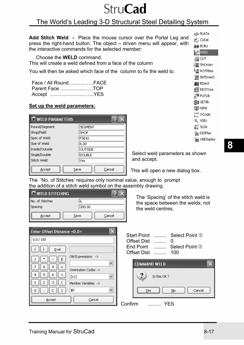
Exercise 8 StruCad Modify Portal Frame
Training Manual for StruCad 8-17
8
The World’s Leading 3-D Structural Steel Detailing System
Add Stitch Weld - Place the mouse cursor over the Portal Leg and press the right-hand button. The object – driven menu will appear, with the interactive commands for the selected member:
Choose the WELD command. This will create a weld defined from a face of the column You will then be asked which face of the column to fix the weld to. Face / All Round……………FACE Parent Face ..………………TOP Accept ….…………………..YES Set up the weld parameters:
Select weld parameters as shown and accept. This will open a new dialog box.
The ‘No. of Stitches’ requires only nominal value, enough to prompt the addition of a stitch weld symbol on the assembly drawing.
The ‘Spacing’ of the stitch weld is the space between the welds, not the weld centres.
Start Point ......... Select Point Offset Dist ......... 0 End Point ......... Select Point Offset Dist ......... 100
Confirm ......… YES

Exercise 8 StruCad Modify Portal Frame
8-18 Training Manual for StruCad
The World’s Leading 3-D Structural Steel Detailing System
NOTE: As always with welds, the weld is defined in the direction of the arrows on the member face.
Save as a Putlib, and copy to the other Portal Leg Base.
(12) Create Assemblies of Portal Legs and Columns • Create an Assembly
If you try to create an assembly of the Column and Portal Leg using the 2Dass command, as with the truss, the following error message will appear.
This message is telling us that the program does not recognise the selected members as ‘Two Dimensional’, which means we have to create our assembly in a different manner.

Exercise 8 StruCad Modify Portal Frame
Training Manual for StruCad 8-19
8
The World’s Leading 3-D Structural Steel Detailing System
The procedure is to first collect together all members that are in the same plane or orientation, into ‘Two Dimensional Groups’ and then define the groups together into an assembly using the command ‘DEFAss’
Create 2D Groups - From the Icon Toolbar menu, select the ‘2Dgroup’ command
Select the option ‘ADD’
With this command select all members that are in the same plane or orientation, (on this occasion there will be only to be one member in each group, but there may be any number in a group up to a maximum of 500!). Select the Column and confirm selection with middle mouse button. The following message will appear.
Select ‘Yes’, the Column will ‘Highlight’ showing it to be a member of a ‘Group’ Press middle mouse button to bring back the 2DGroup command and repeat the procedure for the Portal Leg.
We now have two separate 2D Groups, which need to be combined together into an assembly.
Create Assembly - From the Icon Toolbar menu, select the ‘DEFAss’ command
Select the option ‘ADD’ With this command now select each 2D Group in turn and confirm your selection using middle mouse button. The groups will now be combined into an assembly, as indicated by coloured ‘Blobs’ at both ends of each member in the assembly.

Exercise 8 StruCad Modify Portal Frame
8-20 Training Manual for StruCad
The World’s Leading 3-D Structural Steel Detailing System
(13) Add Haunched Moment Connections to Portal Beam • Create Haunch Macro hmep2 Open MACPar Select General Purpose or Haunch and then HMEP
Right-click HMEP; Copy to Local to create a new local version Name as: HMEP2 Modify Local HMEP2 as you wish to produce a suitable connection. Now add HMEP2 to both ends of Portal Beam, Update the model and load the joint at one end of beam. You will see that the Portal Beam has created a connection with the main Column and not with the Portal Leg.
This is happening because there is a choice of two members for the Portal Beam to connect to, and there is nothing to point the connection to the correct member. In the same way that fittings need to be associated with the correct parent member, macros also, occasionally, need to be associated with the correct members. This association is created by the use of Orientation Codes This orientation code, once determined, can be added into the member attributes dialog box in the appropriate location, i.e. Connect End ‘A’ and Connect End ‘B’, referring to the ‘A’ and ‘B’ ends of the member. The relevant code e.g. –y2, is added in the appropriate location, enclosed by square brackets. i.e. [-y2] Using the ‘Connect’ Macro can do all of this quickly and easily.

Exercise 8 StruCad Modify Portal Frame
Training Manual for StruCad 8-21
8
The World’s Leading 3-D Structural Steel Detailing System
Using the Connect Macro - From the Drop-Down Menu select, Modify / Member Ends / Connect
The prompt will now ask you to ‘Select the end of the member to be connected’. Select the Portal Beam. The prompt will now ask you to ‘Select the member to connect to’. Select the Portal Leg (select the Icon to ensure you select the correct member) Update and re-load the joint.
The Portal Beam is now connected to the correct member.
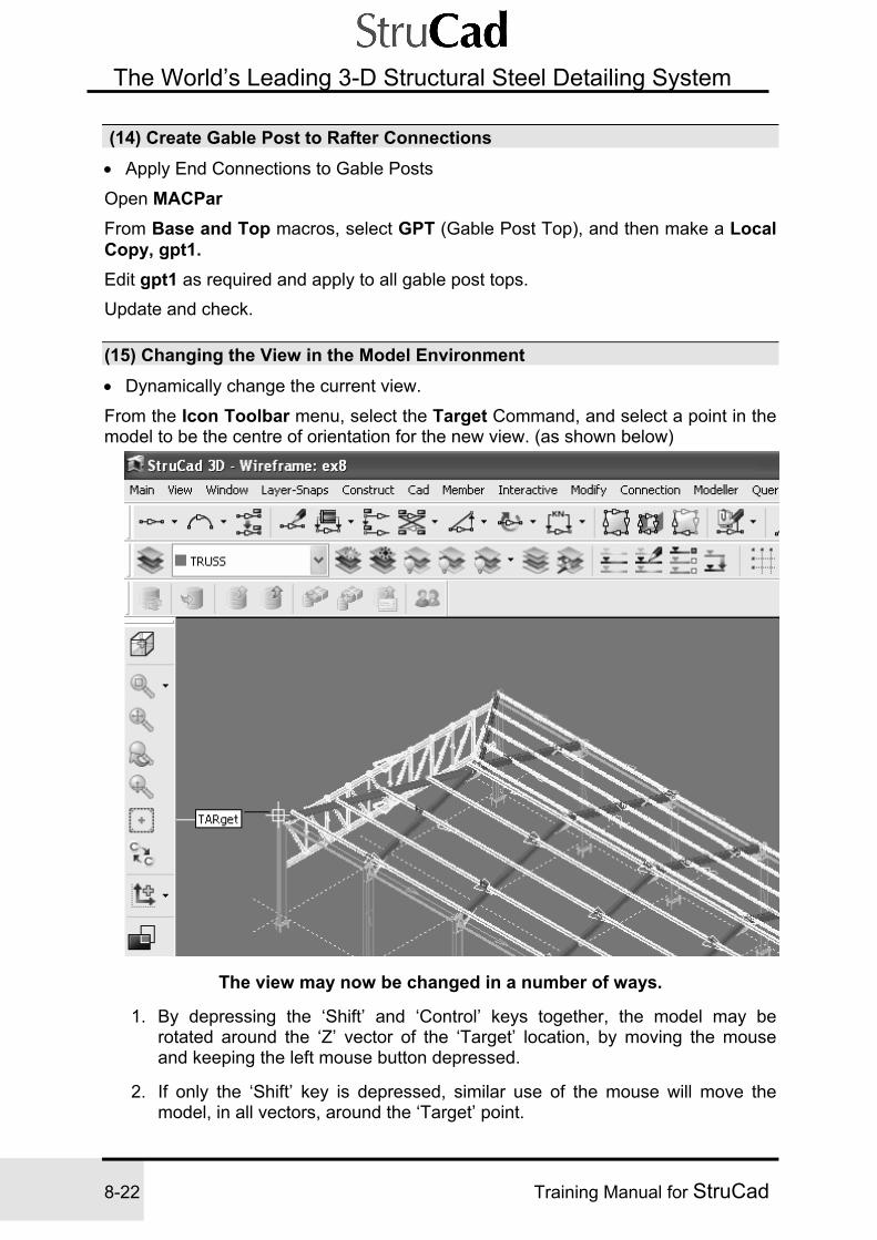
Exercise 8 StruCad Modify Portal Frame
8-22 Training Manual for StruCad
The World’s Leading 3-D Structural Steel Detailing System
(14) Create Gable Post to Rafter Connections • Apply End Connections to Gable Posts
Open MACPar
From Base and Top macros, select GPT (Gable Post Top), and then make a Local Copy, gpt1. Edit gpt1 as required and apply to all gable post tops. Update and check.
(15) Changing the View in the Model Environment • Dynamically change the current view.
From the Icon Toolbar menu, select the Target Command, and select a point in the model to be the centre of orientation for the new view. (as shown below)
The view may now be changed in a number of ways.
1. By depressing the ‘Shift’ and ‘Control’ keys together, the model may be rotated around the ‘Z’ vector of the ‘Target’ location, by moving the mouse and keeping the left mouse button depressed.
2. If only the ‘Shift’ key is depressed, similar use of the mouse will move the
model, in all vectors, around the ‘Target’ point.

Exercise 8 StruCad Modify Portal Frame
Training Manual for StruCad 8-23
8
The World’s Leading 3-D Structural Steel Detailing System 3. With the ‘Shift’ key depressed and use of the right mouse button, the model
may be dynamically panned in all directions.
4. Use of a ‘Wheel Mouse’ will allow ‘Zoom In’ and ‘Zoom Out’, of points, selected as required, with the mouse cursor.
Note - As an alternative to using the ‘Target’ command, a ‘Target’ may be created with a double ‘click’ of the left mouse button, whilst the ‘Shift’ key is depressed.
(16) Checking Fitting Ownership in the Model Environment
Ensure that the Solid Toggle command, SOLToggle is switched on, i.e. the frame is shown in solid format.
From the Icon Toolbar menu, select the COLSol Command, and select the option ‘Fittings’, ‘By Shop’.
All of the members in the model will now be shown with all ‘fittings’, which are attached to that member, shown in the same colour. This makes it easy to check that fittings are attached to the correct members, when adjacent members are in differently coloured model layers.

Exercise 8 StruCad Modify Portal Frame
8-24 Training Manual for StruCad
The World’s Leading 3-D Structural Steel Detailing System
The COLSol Command may also be used to display Members and Fittings by Parent using either the Wire colour or the $ layer colour.
Exit and save changes

Exercise 8 StruCad Modify Portal Frame
Training Manual for StruCad 8-25
8
The World’s Leading 3-D Structural Steel Detailing System
NOTES

Exercise 8 StruCad Modify Portal Frame
8-26 Training Manual for StruCad
The World’s Leading 3-D Structural Steel Detailing System
NOTES

Exercise 9 StruCad Interactive Connections
Training Manual for StruCad 9-1
9
The World’s Leading 3-D Structural Steel Detailing System
Exercise 9
INTERACTIVE DOUBLE ANGLE CLEAT CONNECTIONS (New model)
The object of this exercise is to create a new portal structure, and to connect two secondary beams on the first floor using an interactively created double angle cleat connection.
SEQUENCE
(1) Create Grid Lines and Levels
(2) Add First Floor Beams and Macro Endtypes
(3) Add Eaves Level Beams
(4) Add Rafters
(5) Add Columns
(6) Add Interactive Double Angle Cleats

Exercise 9 StruCad Interactive Connections
9-2 Training Manual for StruCad
The World’s Leading 3-D Structural Steel Detailing System
Exercise 9 INTERACTIVE DOUBLE ANGLE CONNECTIONS
HINT Whilst working interactively on a connection, periodically save your endtype as a temporary Putlib (with a “temporary” name) in case anything goes wrong (such as a power-cut) - you will then not lose the work that you have done so far.
PROCEDURE
(1) Create Grid Lines and Levels Right-click at the left-hand side of the screen to get the left-hand floating menu of commands for laying out and constructing a model:
GLayout No parallel to X axis = 3 Spacing = 7500 No parallel to Y axis = 3 Spacing = 10000 Grid Origin (0,0,0) - Accept
LEVEl USBP -500 Green First 6000 Cyan Eaves 8000 Yellow Apex 11000 Magenta

Exercise 9 StruCad Interactive Connections
Training Manual for StruCad 9-3
9
The World’s Leading 3-D Structural Steel Detailing System
(2) Add First Floor Beams and Macro Endtypes sk 9.1 • Change Working Level to First Floor
SETLEv (Select from left-hand floating menu) Select - First
• Add Primary Members
Member - MEMber (Select from drop-down menu) Stock .................... 457x191x67UB (for members vertical on screen)
• Add Secondary Members
Sizes as shown on Sketch sk 9.1
• Add Endtypes
ENDType (Select from top left floating menu)
( Create your own fep1 macro first, then add to beams )
As shown on Sketch SK 9.1

Exercise 9 StruCad Interactive Connections
9-4 Training Manual for StruCad
The World’s Leading 3-D Structural Steel Detailing System
(3) Add Eaves Level Beams sk 9.2 • Change Working Level to Eaves
SETLEv (Select from left-hand floating menu) Select - Eaves
LAYER ... (Select from left-hand floating menu) EDIT LAYERS First - Off
• Add Eaves Members
Member - MEMber (Select from drop-down menu) Stock Size .......... 305x305x97UC Local X Offset.... -100
(To offset the beam 100mm outside the building) Local Y Offset.... -500 (drops the beam vertically 500mm)
See Sketch sk 9.2
NOTE: The direction in which eaves beams are input allows us to keep the same offsets on all of the beams (the member’s local X-Y axes are all pointing the same way).

Exercise 9 StruCad Interactive Connections
Training Manual for StruCad 9-5
9
The World’s Leading 3-D Structural Steel Detailing System
(4) Add Rafters sk 9.3 • Change Working Level to Apex
SETLEv (Select from left-hand floating menu) Select - Apex
• Clarify the Working View
View - VIEW ... ISO ABOVE (4 o’clock) (From drop-down menu)
• Create a New Layer for the Rafters
Layer-Snaps - LAYER - New (From drop-down menu) Rafters ... Magenta
• Insert Rafters
Member - MEMber (From drop-down menu)
Stock Size .............. 533x210x82UB Top of Steel .......... On
Start Joint ..............END (of Eaves Beam)
End Joint .............. INT (of grids at apex level)
Either repeat for the other rafters, or use copy.

Exercise 9 StruCad Interactive Connections
9-6 Training Manual for StruCad
The World’s Leading 3-D Structural Steel Detailing System
(5) Add Columns sk 9.4
• Clarify the Working View
SETLEv Select - USBP
Layer-Snaps - LAYER Rafters ......... Off
Layer-Snaps - LAYER - New Columns ......... Green
• Input Columns
Member - MEMber Stock Size .......... 533x210x82UB
NOTE: For setting-out-points (SOPs) of columns, use Top of Steel and Rotation to set the columns out correctly.
• Update your Model
Modeller - UPdate (Select from drop-down menu)

Exercise 9 StruCad Interactive Connections
Training Manual for StruCad 9-7
9
The World’s Leading 3-D Structural Steel Detailing System
(6) Add Interactive Double Angle Cleats • Clarify Working View
SETLEv Select - First (All other layers can be turned off)
LAYER Columns ... Off Eaves ... Off UPdate • Load the Joint Right mouse -click over the joint between the 356UB and the 457UB on Grid Line 1.
Select the LOADJnt command - this will load the joint where the two wires meet.
• Shorten the Member
Query - DIST (Select from drop-down menu) Determine distance to shorten by measuring half the web thickness of the continuous beam and adding 11mm (1mm clearance and 10mm projection of the angles). Remember to use SNAPS.
Move the mouse cursor over the non-continuous 356UB member (in sk 9.1) and press the right-hand button on the mouse. The floating menu of interactive commands available for the selected member will appear:
Choose the SHORTEN command. Then select Shorten by Distance and shorten the 356UB member by the distance previously worked out by your measurement.

Exercise 9 StruCad Interactive Connections
9-8 Training Manual for StruCad
The World’s Leading 3-D Structural Steel Detailing System
• Clarify the Working View
Use View - Toggle Ports, Window - WI, etc (from drop-down menus), so as to get the view shown in Sketch sk 9.5.
• Notch the Member
DIST
Determine the size of the notch by measuring between Points and in Sketch sk 9.5.
Make a note of the distance in the X-direction and the distance in the Z-direction for use when we create the cut.
• Cut the Member Before we cut the member you need to know how the cut command works. 1. The first step is to move the cursor over the member (or fitting) to be cut, and then press the right-hand button on the mouse. This gives you a menu of interactive commands that can be applied to the selected member (or fitting).
Choose the Cut command.
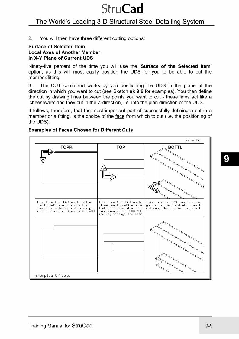
Exercise 9 StruCad Interactive Connections
Training Manual for StruCad 9-9
9
The World’s Leading 3-D Structural Steel Detailing System
2. You will then have three different cutting options:
Surface of Selected Item Local Axes of Another Member In X-Y Plane of Current UDS
Ninety-five percent of the time you will use the ‘Surface of the Selected Item’ option, as this will most easily position the UDS for you to be able to cut the member/fitting. 3. The CUT command works by you positioning the UDS in the plane of the direction in which you want to cut (see Sketch sk 9.6 for examples). You then define the cut by drawing lines between the points you want to cut - these lines act like a ‘cheesewire’ and they cut in the Z-direction, i.e. into the plan direction of the UDS. It follows, therefore, that the most important part of successfully defining a cut in a member or a fitting, is the choice of the face from which to cut (i.e. the positioning of the UDS).
Examples of Faces Chosen for Different Cuts
BOTTLTOPTOPR
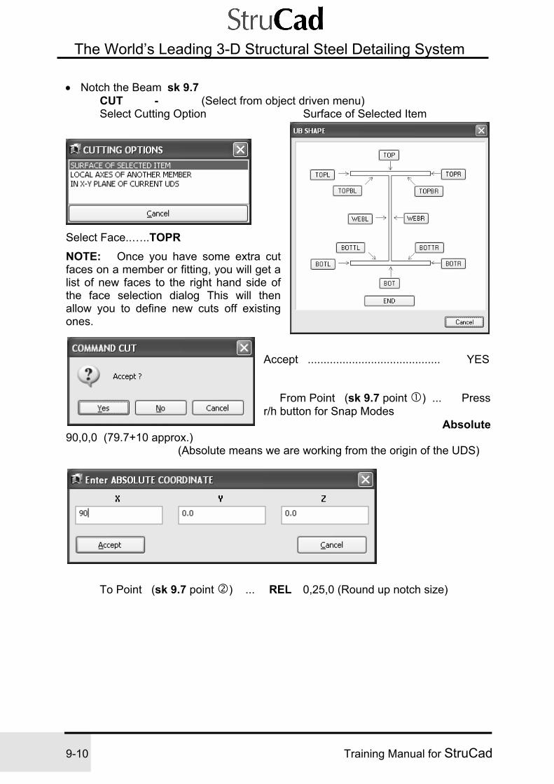
Exercise 9 StruCad Interactive Connections
9-10 Training Manual for StruCad
The World’s Leading 3-D Structural Steel Detailing System
• Notch the Beam sk 9.7 CUT - (Select from object driven menu) Select Cutting Option Surface of Selected Item
Select Face..…..TOPR
NOTE: Once you have some extra cut faces on a member or fitting, you will get a list of new faces to the right hand side of the face selection dialog This will then allow you to define new cuts off existing ones.
Accept .......................................... YES
From Point (sk 9.7 point ) ... Press r/h button for Snap Modes Absolute
90,0,0 (79.7+10 approx.) (Absolute means we are working from the origin of the UDS)
To Point (sk 9.7 point ) ... REL 0,25,0 (Round up notch size)

Exercise 9 StruCad Interactive Connections
Training Manual for StruCad 9-11
9
The World’s Leading 3-D Structural Steel Detailing System
Enter Cut Face Name <F01> Choose 1 … Accept (This can be anything, but don’t repeat cut names on the same member) To Point ( ). REL -100,0,0 (The distance in the X-direction for the cut could be -10, -100 or -1000
as it is only defining the direction of the cut.) Enter Cut Face Name <F02> - Choose 2 .… Accept Enter Radius between Faces 1/2. - Choose 0.0 ….. Accept
To Point/ <CR> to Finish ............. Press Return
Cut Slope ..................................... Accept
The blue line you see is the cut definition; this does not appear on any of your fabrication details - it is only visible in the Interactive/Loadjoint Environment. Erasing the blue line will not get rid of the cut. To delete a cut you use the DELETE command and select the cut definition line; this will then replace the steel that you cut away.
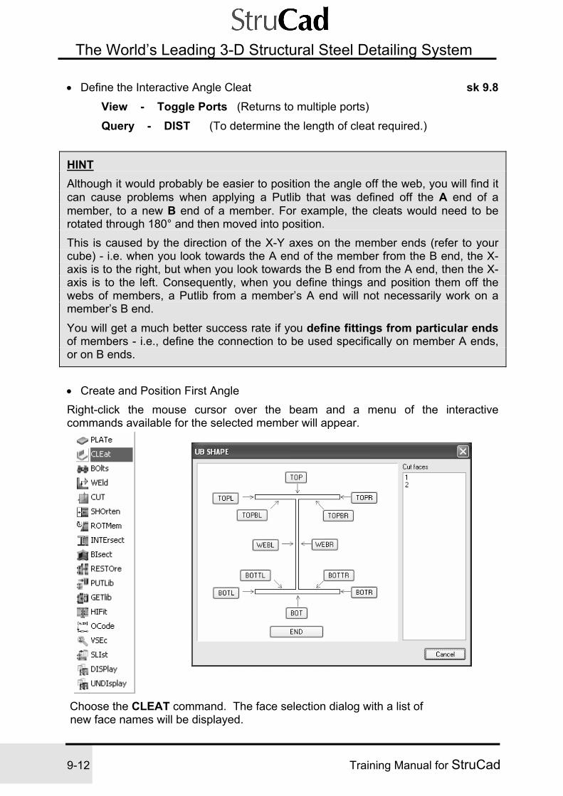
Exercise 9 StruCad Interactive Connections
9-12 Training Manual for StruCad
The World’s Leading 3-D Structural Steel Detailing System
• Define the Interactive Angle Cleat sk 9.8
View - Toggle Ports (Returns to multiple ports)
Query - DIST (To determine the length of cleat required.)
HINT Although it would probably be easier to position the angle off the web, you will find it can cause problems when applying a Putlib that was defined off the A end of a member, to a new B end of a member. For example, the cleats would need to be rotated through 180° and then moved into position. This is caused by the direction of the X-Y axes on the member ends (refer to your cube) - i.e. when you look towards the A end of the member from the B end, the X-axis is to the right, but when you look towards the B end from the A end, then the X-axis is to the left. Consequently, when you define things and position them off the webs of members, a Putlib from a member’s A end will not necessarily work on a member’s B end.
You will get a much better success rate if you define fittings from particular ends of members - i.e., define the connection to be used specifically on member A ends, or on B ends.
• Create and Position First Angle Right-click the mouse cursor over the beam and a menu of the interactive commands available for the selected member will appear.
Choose the CLEAT command. The face selection dialog with a list of new face names will be displayed.

Exercise 9 StruCad Interactive Connections
Training Manual for StruCad 9-13
9
The World’s Leading 3-D Structural Steel Detailing System
Select Face (of Beam) ... END Accept? ........................................ Yes Set up Cleat Parameters Cleat Size ...................................... 100x100x10RSA
(A cleat does not have to be an angle - it can be anything Defined in the section catalogue)
Cleat Length ................................. 300 Cleat Grade ................................... S275JR Cleat Ownership .......................... Shop Current Dummy ........................................ No Ignore Cleat Name and Group Name Accept? ....................................... Yes Select Face (of Angle) .................... TOPB Accept? ......................................... Yes Cleat Rotation ............................... Rotate by Angle Rotation Angle ............................. 90 Accept? ....................................... Yes
Base Point .................................... LINT (See Sketch sk 9.8)
New Point .................................... SINT (See Sketch sk 9.8)
Sk 9.8
This has moved the angle cleat into position horizontally, so we must now
move it into position vertically.

Exercise 9 StruCad Interactive Connections
9-14 Training Manual for StruCad
The World’s Leading 3-D Structural Steel Detailing System
Right-click on the cleat and select SMOve from the Cleat (Interactive) object - driven menu of commands that apply to the cleat. (You could alternatively select Smove from bottom-left floating menu, but then you would have to Select the Fitting anyway.) Base Point ........................ SINT (see sk 9.9) (Remember the rules For SINT -see Exercise 6 (4)) New Point ........................ SINT (Sketch sk9.9)
• Copy the Second Angle
Cleat (Interactive) - SCOpy (Select from Interactive Object menu) Base Point ......................... Accept (0,0,0) New Point ......................... Accept (0,0,0) Number of Copies ............ 1 There are now 2 angles, one on top of the other This saves us time having to input a new cleat!
Cleat (Interactive) - EDCleat (Select from Interactive Object menu)
Change the cleat rotation, by 180, to -90 and Accept.

Exercise 9 StruCad Interactive Connections
Training Manual for StruCad 9-15
9
The World’s Leading 3-D Structural Steel Detailing System
• Re-Position the New Angle
Cleat (Interactive) - SMOve (Select from Interactive Object menu) Use SINT and LINT in your ‘plan’ view and your ‘front’ view to position the
cleat correctly. Remember that you can only use SINT and LINT together, and you can only work in one view port in any one command.
• Add Bolts Right-click on the angle on the nearside of the web. Cleat (Interactive) - BOlts (Select from Interactive Object menu) Set up the Bolt Group parameters Select a Face (of the Angle) ........... WEBR Accept? ........................................ Yes Number in X .................................. 3 Pitch in X ..................................... 100 Number in Y ................................. 1 (All other parameters can be accepted) Enter Bolt Origin ......................... Absolute X=50, Y=45, Z=0
NOTE: Y=45 because we are working with a standard 55 back mark on the angle. The UDS of the face that we have chosen is on the inside face of the angle, therefore we need to subtract the angle leg thickness.
Accept? ...................................... Yes
BOlts (Right-click on the appropriate angle to select its Interactive Object menu) Repeat for the other two bolt groups, one in each angle, and connecting to the continuous member. Use the correct faces for each. StruCad will determine any differences between the web and end connections.
• Save Work and Exit Right-click at the right-hand side of the screen to get the right-hand floating menu of commands for laying out and constructing a model
Putlib (Select from right-hand side floating menu, then select the member end. Alternatively, right-click on the member)
Library Name ……………...ex9-001 ( the first putlib created on Contract ex9) Initials …….....………..……..(Type your initials) Description .....……….……..Double Angle Cleat Connection for 356 UB Apply Current....………….....Yes Save Global.......…………….No (just save a local copy) Add or Remove Objects ...…No (Only use if not saving all objects in joint) All Objects .......……………..All (everything defined from the Current Member end) Member end actions .… Yes (All shortens, rotations, intersects etc on member)

Exercise 9 StruCad Interactive Connections
9-16 Training Manual for StruCad
The World’s Leading 3-D Structural Steel Detailing System
• Apply to Member B End and Update (Endtype – Interactive Local) 1. Check to see whether the connection works on both ends of the member. 2. Repeat Exercise 9 for the 457UB connection to the continuous 457UB (see Sketch sk 9.1).
NOTES

Exercise 10 StruCad Interactive Sloping Connections
Training Manual for StruCad 10-1
10
The World’s Leading 3-D Structural Steel Detailing System
Exercise 10
INTERACTIVE SLOPING CONNECTIONS (Using model from Exercise 9)
In this exercise we will try three different ways of interactively making a connection on a sloping beam, to see which is the best method.
SEQUENCE
(1) Add Sloping Beam
(2) Update the Model
(3) Load the Joint
(4) Method 1 - Intersect the Sloping Beam with the Column
(5) Method 2 - Cut The Sloping Beam Parallel to the Column Face
(6) Method 3 - Rotate the Member End to be Parallel to the Column Flange
(7) Shorten the Sloping Beam
(8) Add End Plate, Welds and Bolts
(9) Save Work and Exit
(10) Repeat to make a Sloping Connection to the Underside of Floor Beam

Exercise 10 StruCad Interactive Sloping Connections
10-2 Training Manual for StruCad
The World’s Leading 3-D Structural Steel Detailing System
Exercise 10 INTERACTIVE SLOPING CONNECTIONS
PROCEDURE
(1) Add Sloping Beam sk 10.1
• Change Working Level to USBP and Set Layer
SETLEv... USBP Columns and First layers should be turned on and all other layers off.
Set Layer .…..First (Set layer using Combo-Box) Layers - Columns - ON • Add Sloping Member
Member - MEMber Stock Size .............. 254x146x31UB Top of Steel ......... On Start Joint .............. REF - INT Z=2000 End Joint .............. MID

Exercise 10 StruCad Interactive Sloping Connections
Training Manual for StruCad 10-3
10
The World’s Leading 3-D Structural Steel Detailing System
(2) Update the Model UPdate (So we can load the joints of the sloping member)
(3) Load the Joint • Load the Joint between the Sloping Member and the Column Right-click on the joint between the sloping 254UB and the column on Grid A1 Loadjoint
(4) Method 1 - Intersect the Sloping Beam with the Column Right-click the mouse cursor over the sloping 254UB member for the menu of interactive commands applicable to the selected member:
Right-click on the member to open object-driven menu.
Select - Intersect Member to Intersect With... Select the Column Enter Clearance .............................. 13 (12mm plate + 1mm clearance) Intersect ......................................... Profile
• Add End Plate You can now add an end plate as you would normally, selecting the CUT1 face of the beam to which to connect the plate. You will see the UDS is at its new position, which makes it extremely easy to position the plate correctly.
• Restore the Beam to its Original State
Restore Are you sure you want to restore Current End? ... Yes

Exercise 10 StruCad Interactive Sloping Connections
10-4 Training Manual for StruCad
The World’s Leading 3-D Structural Steel Detailing System
(5) Method 2 - Cut the Sloping Beam Parallel to the Column Face sk 10.2 Cut (Select from top left floating menu) Use the Plan View port Select parent. Member you want to cut Cutting Options .............................. Local Axes of another member Select a Member ........................... Select the column From Point .................................... REF - INT Y= -13 To Point ....................................... REL X= -150 Cut Face Name .............................. 1 (Face in sk 10.2) To Point/<CR> to Finish .............. <CR> (press Return) Cut Slope ...................................... Accept
• Add End Plate
When you add a plate to the face F01 of the member you will get exactly the same situation that you had when using the INTERSECT command. The UDS of the end of the Current Member is in its new position, so adding the plate is quite straightforward.
• Restore the Beam to its Original State
Restore

Exercise 10 StruCad Interactive Sloping Connections
Training Manual for StruCad 10-5
10
The World’s Leading 3-D Structural Steel Detailing System
(6) Method 3 - Rotate the Member End Parallel to the Column Flange sk 10.3
• Determine the Angle of the Sloping Member Right-click the mouse over the sloping beam for the menu of its interactive commands:
First choose the Slist command. The Pad will display the list of the beam’s properties. Make a note of the Variable $VSLOPE, the vertical slope, which will be about 31 degrees.
• Rotate the Member End
Member (Interactive) - Rotmem (From Interactive Object menu)
Rotmem ...……......... X ROTATE BY ANGLE (Rotates the Y around the X-axis) Rotation Angle in X ………. 31 degrees Alternatively, at the prompt: Enter a
Parametric Expression.……..$VSLOPE
Press Evaluate Expression... This will give you 30.964 degrees (a more accurate slope) in this window. Select - ACCEPT
This will rotate your member end so that it is parallel to the column flange. It will also have rotated the member’s UDS, therefore making it easier to position the end plate (see sk 10.3 and sk 10.4).

Exercise 10 StruCad Interactive Sloping Connections
10-6 Training Manual for StruCad
The World’s Leading 3-D Structural Steel Detailing System
(7) Shorten the Sloping Beam sk 10.4
• Create a Construction Line to give Two Points at which to shorten the Member.
Copy (Select from drop-down menu) Select Objects ........................... Select outside flange Line A Base Point ................................. NEAR
(Anywhere on the flange) New Point .................................. REL Y=13
(12mm plate+1mm clearance)
• Shorten the Member
Member (Interactive) - Shorten ... By 2 Points From Point .................................. SINT To Point ..................................... SINT

Exercise 10 StruCad Interactive Sloping Connections
Training Manual for StruCad 10-7
10
The World’s Leading 3-D Structural Steel Detailing System
• Alternative Method of Shortening the Member
1. Measure the distance required, which is actually 555.84 (see sk 10.4)
2. Shorten ... by Distance Enter distance to shorten .......... 555.84
You have now used three different ways of shortening the sloping beam in preparation for adding the rest of its connection to the column. These were (a) INTERSECT, (b) CUT, and (c) ROTMEM. Each of these methods have different benefits; i.e. INTERSECT may be easier to apply, but ROTMEM makes it easier to apply an end plate etc. The choice of which to use will be yours,depending on which method you find easier to use and remember. With the beam now shortened, proceed with the rest of the connection.
(8) Add End Plate, Welds and Bolts sk 10.5 • Create the connection shown in Sketch sk 10.5 using commands that you have
already learnt in previous exercises.
(9) Save Work and Exit Member (Interactive) - Putlib (Right-click beam for Object menu) Library Name ……………...ex10-001 ( the first Putlib created on Contract ex10) Initials …….....………..……..(Type your initials) Description .....……….……..Sloping 254 UB Connection to Column Apply Current....………….....Yes Save Global.......…………….No (just save a local copy) Add or Remove Objects ...…No (Only use if not saving all objects in joint) All Objects .......……………All (everything defined from the Current Member end) Member end actions .………Yes (All shortens, rotations, intersects etc on member)

Exercise 10 StruCad Interactive Sloping Connections
10-8 Training Manual for StruCad
The World’s Leading 3-D Structural Steel Detailing System
(10) Repeat to Make a Sloping Connection to the Underside of the Floor Beam
• Create a similar connection at the B end of the sloping beam.
When rotating the member end, use the ‘X Rotate by Point’ option as shown in sk 10.6.
• Save as a Putlib and Unloadjoint
Putlib
Library Name ……………...ex10-002 Initials …….....………..……..(Type your initials) Description .....……….…….. Sloping 254 UB Connection to Underside of Beam Apply Current....………….....Yes Save Global.......…………….No (just save a local copy) Add or Remove Objects ...…No (Only use if not saving all objects in joint) All Objects .......……………..All (everything defined from the Current Member end) Member end actions .………Yes (All shortens, rotations, intersects etc on member)
• Update, View and Check the Connections

Exercise 10 StruCad Interactive Sloping Connections
Training Manual for StruCad 10-9
10
The World’s Leading 3-D Structural Steel Detailing System
NOTES

Exercise 10 StruCad Interactive Sloping Connections
10-10 Training Manual for StruCad
The World’s Leading 3-D Structural Steel Detailing System
NOTES

Exercise 11 StruCad Interactive Haunch Connection
Training Manual for StruCad 11-1
11
The World’s Leading 3-D Structural Steel Detailing System
Exercise 11
INTERACTIVE HAUNCH CONNECTION - UTILISING DUMMY MEMBERS (Using model from Exercise 10)
This exercise enables you to prepare eaves and apex haunches for subsequent connection.
SEQUENCE
(1) Create a Suitable Base Plate for the Columns using the RBP Macro
(2) Load the Eaves Joint
(3) Bisect the Rafter and Column and Save Connection
(4) Apply End Type to Other Members in the Wireframe
(5) Load the Apex Joint
(6) Bisect the Rafters and Save Connection
(7) Apply End Type to Other Members in the Wireframe
(8) Add Dummy Member and Update
(9) Create the Haunch Connection
(10) Apply End Type to Dummy Members at the Other Apex Connections
(11) Create Assemblies and Update

Exercise 11 StruCad Interactive Haunch Connection
11-2 Training Manual for StruCad
The World’s Leading 3-D Structural Steel Detailing System
Exercise 11 INTERACTIVE HAUNCH CONNECTION -
UTILISING DUMMY MEMBERS
PROCEDURE
(1) Create a Suitable Base Plate for the Columns using the RBP Macro
• Using the RBP macro, apply a column base to all columns. Use the commands you have learned in previous exercises (e.g. Exercise 4 (1)).
Connection - ENDType (Select from drop-down menu)
(2) Load the Eaves Joint • Clarify the Working View
LAYER…... EDIT LAYERS Rafters ...................On
• Load the Eaves Joint Right-click on the eaves joint on Grid Line A1
LOADJnt (Select from object menu)

Exercise 11 StruCad Interactive Haunch Connection
Training Manual for StruCad 11-3
11
The World’s Leading 3-D Structural Steel Detailing System
(3) Bisect the Rafter and the Column and Save Connection sk 11.1 • Bisect the Column into the Rafter Right-click the mouse on the column to get the menu of interactive commands available for the selected member:
Choose the BIsect command.
Select Member to bisect with... Select the rafter Enter Clearance ........................... 0

Exercise 11 StruCad Interactive Haunch Connection
11-4 Training Manual for StruCad
The World’s Leading 3-D Structural Steel Detailing System
• Bisect the Rafter into the Column Right-click the mouse on the rafter for the menu of interactive commands available for the selected member.
Choose the BIsect command Select Member to bisect with... Select the column Enter Clearance ........................... 0
• Save the Connection Right-click the mouse at the top left of the screen for the floating menu of Interactive Creation commands:
Choose the PUTAllib command.
The PUTALLIB command will save all relevant ends within the connection and prompt for the user to name them.
HINT You can change the PARAM, “Prefix for PUTLIB Endtype” parameter to ex11- to enable you to save Putlibs with this prefix from now on in this model from Exercise 9.
Save Putlibs with a suitable name and description, E.g. ex11-001, -002 (the first and second Putlibs on Exercise 11)
(4) Apply Endtypes to other Members in the Wireframe UNLoadjnt (Select from top left floating menu)
ENDType (Select from wireframe top left floating menu) Endtype ................................... Interactive Menu Select an Interactive Library ... Select the Putlib you have just created Select Member End ...................Select the B end of all your columns and the A end of all your rafters.
(5) Load the Apex Joint • Load the Apex Joint Right-click on the Apex Joint on Grid Line A1
LOADJjnt (Select from object menu)

Exercise 11 StruCad Interactive Haunch Connection
Training Manual for StruCad 11-5
11
The World’s Leading 3-D Structural Steel Detailing System
(6) Bisect the Rafters and Save Connection • Bisect the First Rafters Right-click on the rafter between Grids A1 and B1:
BIsect Select Member to Bisect with... Select the other rafter Enter Clearance ............................. 0
• Save the Connection
PUTLib………….. (From the same menu) The end should be saved with a suitable name and
description, i.e. ex11-003 (the third Putlib on Exercise 11)
• Bisect the Other Rafter
Right-click the mouse cursor on the other rafter to get the menu of interactive commands for it.
GETlib …………… Select - ex11-003 GETLib will allow you to attach the previously created connection to this rafter.
• Save the Whole Connection
PUTAllib (Save as before) The names should be ex11-004 and ex11-005.
(7) Apply End Types to Other Members in the Wireframe
Unloadjnt (Select from top left floating menu)
ENDType (Select from wireframe top left floating menu) Endtype ......................................Interactive Menu Select an Interactive Library ... Select the Putlib you have just created Select Member End ....................Select the B end of all your rafters.
Alternatively, provided you have already applied the Putlib, you can use the ENDCOPY command to copy connections from one end of a member to other ends. ENDCOPY is under the Connection drop-down menu.
Another alternative for applying end connections to many members at the same time is as follows;-
Switch off all layers except the layer on which your members are located.( In this case the Rafter Layer.)
Now use the EDMem command, select Visible members, and edit end type A or end type B to receive putlibs or macros as required.

Exercise 11 StruCad Interactive Haunch Connection
11-6 Training Manual for StruCad
The World’s Leading 3-D Structural Steel Detailing System
(8) Add Dummy Member and Update sk 11.2
• Create a Dummy Layer
Layer-Snaps - LAYER - New (From drop-down menu) Layer = Dummy Colour = Red NOTE: Putting a member on this layer does NOT automatically make it a Dummy Member
• Add Dummy Member
Member - MEMber (From drop-down menu) Stock ....................254x146x31UB (although the size is not important) Yoff .......................-1000 (to drop the Dummy Member down 1000mm) Dummy ................ On (this makes the member a Dummy) Start Joint ..............INT 1 in sk 11.2 End Joint .............. REL X = 500
2
• Update the Model
Modeller - UPdate (Select from drop-down menu) So that we can load the joint of the dummy member

Exercise 11 StruCad Interactive Haunch Connection
Training Manual for StruCad 11-7
11
The World’s Leading 3-D Structural Steel Detailing System
(9) Create the Haunch Connection sk 11.3, 11.4& 11.5
• Load the Joint between the Dummy Member and the Rafters Right-click the joint between dummy and the rafters LOADJnt • Manipulate Views so that you can see the Dummy and the Rafters
Use ZO, ZI, WI, PAN, etc.

Exercise 11 StruCad Interactive Haunch Connection
11-8 Training Manual for StruCad
The World’s Leading 3-D Structural Steel Detailing System
• Create the Haunch Right-click on the Dummy Member to get the menu of commands applying directly to it.
Select - Cleat (A Cleat can be anything specified in the Section Catalogue) Select a Face (of the Dummy) ... Top (The top of Dummy is 1000mm down from the Apex SOP) Accept? ...........................Yes Cleat Size ........................533x210x82UB (same as rafter) Cleat Length ....................2250 (cut to size later) Cleat Ownership ..............Shop another Select Parent Member ..... Select one of the rafters Select a Face (of the Cleat)Bot(to attach to the top of the Dummy) Accept? .....................................Yes Cleat Rotation ...........................Rotate by angle Enter Rotation Angle ................ 90 degrees Accept? .....................................Yes
Base Point ................................SINT in sk 11.4 New Point .................................SINT in sk 11.4
sk 11.4

Exercise 11 StruCad Interactive Haunch Connection
Training Manual for StruCad 11-9
11
The World’s Leading 3-D Structural Steel Detailing System
• Move the Cleat to its Final Position sk 11.5 Right-click on the Haunch Cleat to get the interactive commands applying to that fitting:
Choose the Smove command. Base Point ................................. 0,0,0 (Press Enter) New Point .................................. REL Y = 1200
sk 11.5

Exercise 11 StruCad Interactive Haunch Connection
11-10 Training Manual for StruCad
The World’s Leading 3-D Structural Steel Detailing System
• Cut the Haunch Right-click on the Haunch Cleat to get the interactive commands applying to that fitting:
Cleat (Interactive) - Cut Cutting Options ........................... Surface of selected item
Select Face (of Cleat) .................. TOPL (Although any face looking at the cleat in elevation will do, any one of six faces would have the same effect)
Accept? ...................................... Yes
From Point .................................. SINT in sk 11.5 To Point ...................................... SINT in sk 11.5 Cut Face Name ........................... F01
To Point ...................................... SINT in sk 11.5 Cut Face Name ............................ F02 Radius Between Faces ................ 0 To Point/<CR> To Finish .......... <CR> (Press Enter) Select Vertex to Keep ............... Select part of the cleat as in (sk11.5) You will see that, by selecting the vertex of the middle part of the cleat, the CUT command finds the nearest end of the line you select. This means that it keeps the outside portion of the cleat, i.e. not the part we want to keep. So, to be able to define the cleat we want, we must define two separate cuts, as shown in Sketch sk 11.6 below. For Cut 1 you will pick SINT’s and as shown on sk 11.6 and then, when you select the vertex to keep, pick the opposite corner of the cleat.
Repeat for Cut 2, picking SINT’s and , and again the vertex to keep will be the opposite corner. You will find that, by cutting the cleat in two separate actions, you can achieve the desired haunch.
Exercise 11 StruCad Interactive Haunch Connection
Training Manual for StruCad 11-11
11
The World’s Leading 3-D Structural Steel Detailing System
• Save Work and Exit Right-click the mouse on the Dummy Member to re-define it as the current end and get the menu of interactive commands applying to it.
PUTLib Library Name ……………...ex11-004 Initials …….....………..……..(Type your initials) Description .....……….……..Haunch Connection at Apex Apply Current....………….....Yes Save Global.......…………….No (just save a local copy) Add or Remove Objects ...…No (Only use if not saving all objects in joint) All Objects .......……………..All (everything defined from the Current Member end) Member end actions .………Yes (All shortens, rotations, intersects etc on member)
Unloadjnt
(10) Apply Endtype to Dummy Members at the Other Apex Connections
• Copy the Dummy Member, complete with Cleat
Modify - Copies - MCopy (Select from drop-down menu) Select Objects ........................... Select the Dummy Member Base Point ................................. INT (at the apex on Grid Line 1) New Point .................................. INT (at the apex on Grid Line 2) Number of Copies ..................... 2
• Update and Check the Model
UPdate Use LOADJnt to check the other apex connections.
HINT You can repetitively use the middle button of the mouse when checking round a model, since it will toggle automatically between LOADJNT and UNLOADJNT.
NOTE: You cannot erase the dummy members, as they have the Haunch Cleat end types on them. The rafters at the apex already have a Putlib on their ends, the Bisect, so the dummy has to be present to position the haunch.

Exercise 11 StruCad Interactive Haunch Connection
11-12 Training Manual for StruCad
The World’s Leading 3-D Structural Steel Detailing System
(11) Create Assemblies and Update sk 11.6
• Create a 2D Assembly of the Members on Grid Line 1
2DASS (Select from Icon menu, or type 2dass)
2DAssembly ................................. Add Select Reference Member ............ Select Member (the Reference Member is assigned the Assembly Mark)
Select Members To Add .............. Select Members , and (Order isn’t really important)
Accept
6
NOTE: The Dummy Member does not need to be part of the Assembly.
• Repeat for Members on Grid Lines 2 and 3
• Update and Check the Model

Exercise 11 StruCad Interactive Haunch Connection
Training Manual for StruCad 11-13
11
The World’s Leading 3-D Structural Steel Detailing System
NOTES

Exercise 11 StruCad Interactive Haunch Connection
11-14 Training Manual for StruCad
The World’s Leading 3-D Structural Steel Detailing System
NOTES

Exercise 12 StruCad Interactive Eaves Bracket
Training Manual for StruCad 12-1
12
The World’s Leading 3-D Structural Steel Detailing System
Exercise 12
INTERACTIVE EAVES BRACKET CONNECTION (Using model from Exercise 11)
In Exercise 12 you cut the Eaves Beams to fit properly, and then connect them to the columns using interactively created brackets.
SEQUENCE
(1) Load the Eaves Joint
(2) Shorten and Cut the Eaves Beam
(3) Save Endtype and Apply to Other Eaves Beams
(4) Create Similar Connection for Other End of Eaves Beam
(5) Save Endtype and Apply to Ends of Other Eaves Beam
(6) Reload Joint and Measure Distance to Determine Size of Bracket
(7) Create Bracket Cleat and Welds
(8) Create Bracket End Plate and Welds
(9) Create Bolt Groups to Support the Eaves Beams
(10) Check the Connection by Producing Details

Exercise 12 StruCad Interactive Eaves Bracket
12-2 Training Manual for StruCad
The World’s Leading 3-D Structural Steel Detailing System
Exercise 12 INTERACTIVE EAVES BRACKET CONNECTION
Use the commands that you have learnt in previous exercises to complete this exercise. You should only need a total of 3 Putlibs for this exercise!
PROCEDURE
(1) Load the Eaves Joint • Select the joint at Eaves level on Grid Line A2
(2) Shorten and Cut the Eaves Beam sk 12.1
• Shorten the Eaves Beam by 3mm
• Cut the Eaves Beam using Reference Points at and , and perpendicular to .
(Use Top Face)
sk 12.1

Exercise 12 StruCad Interactive Eaves Bracket
Training Manual for StruCad 12-3
12
The World’s Leading 3-D Structural Steel Detailing System
(3) Save End Type and Apply to Other Eaves Beams • Putlib
Use the Putlib system from Exercises 9,10 and 11 to save the endtype as ex12-001.
• Abort, and apply connection to Eaves Beam Ends at the middle columns on Grids A & C
• Update
(4) Create Similar Connections for Other End of Eaves Beam sk 12.2 Shorten and cut to achieve the connection shown.
sk 12.2
Note - (shortening by a negative value will lengthen the member.)
(4a) Alternative method for creating the above Connection
• Load the Eaves joint at Grid Ref A1.
• Getlib ex12-001 and apply.
• Shorten Beam by –103mm
• Select cut and smove relative in the ‘X’ vector by 103mm.

Exercise 12 StruCad Interactive Eaves Bracket
12-4 Training Manual for StruCad
The World’s Leading 3-D Structural Steel Detailing System
(5) Save End Type and Apply to Ends of Other Eaves Beams
• Putlib Save as ex12-002.
• Abort, and apply to Eaves Beam Ends at the end columns on Grids A & C
• Update
(6) Reload Joint and Measure Distances to Determine Size of Bracket sk 12.3
• Loadjoint Load one of your Eaves joints.
sk 12.3
• Distance
Measure the distance using screen intersections between Points and to determine the size and length of cleat required.

Exercise 12 StruCad Interactive Eaves Bracket
Training Manual for StruCad 12-5
12
The World’s Leading 3-D Structural Steel Detailing System
(7) Create Bracket Cleat and Welds sk 12.4
REMINDER Whilst working interactively on a complex connection, it is correct practice to periodically save your endtype as a temporary Putlib (with a “temporary” name), so that you do not lose your all work if anything goes wrong in the next stage.
• Cleat Create the cleat shown, defining it off the column. Position it centrally on the column, and centrally to the Eaves Beams.
sk 12.4
Use the commands that you have learnt in earlier exercises to position the cleat correctly. You will need to measure the distance, and then move the cleat “relatively” from its present position.
• Weld Create an all-round fillet weld (6FW) between the cleat and the column.
NOTE: The all-round welding option only works for a cleat, and not for a plate.
• Putlib Give it a temporary name (e.g. temp-1) to save the work so far.

Exercise 12 StruCad Interactive Eaves Bracket
12-6 Training Manual for StruCad
The World’s Leading 3-D Structural Steel Detailing System
(8) Create Bracket End Plate and Welds sk 12.5
• Distance Measure the exact dimensions of the cleat to determine the size of end plate.
sk 12.5
• Plate Add an end plate for the Eaves Beam Bracket, and position it centrally on the cleat.
As shown in Sketch sk 12.5, create welds as follows: (a) Between the UB Stub and end plate (4 welds in total), (b) An inside profile weld each side of the web, and (c) A weld at the top and bottom of the end plate. Remember to distinguish between inside and outside welds when doing these welds. If you cannot remember, then refer to Exercise 6, or ask your instructor!!
Check the position of your cleat and plate in all four-view ports.
• Putlib Again, save the connection at this point as a temporary back up.

Exercise 12 StruCad Interactive Eaves Bracket
Training Manual for StruCad 12-7
12
The World’s Leading 3-D Structural Steel Detailing System
(9) Create Bolt Groups to Support the Eaves Beams sk 12.6 • Bolts Define a set of 4 bolts to suit the End Plate specified
sk 12.6
• Putlib Re-save the temporary connection.

Exercise 12 StruCad Interactive Eaves Bracket
12-8 Training Manual for StruCad
The World’s Leading 3-D Structural Steel Detailing System
(10) Check the Connection by Producing Details sk 12.7 • Endtype Apply the interactive connection you have created just to this column, and Update.
• Fabmem
Produce Detail Drawings of the column and the two Eaves Beams and whether they are correct.
As you will see when you check the details, the column drawing is correct, but the two eaves beams are incorrect. One of the beams has two holes floating in mid-air, whilst the other has no holes - see Sketch sk 12.7.
sk 12.7
Getting Bolt Groups Right This fault is caused by the bolt you position being the “reference” bolt for the group. It is this bolt that defines the length of the bolts, and also determines to which member the bolt group belongs when the fabrication detail is produced. In this case, the reference bolt passed through the beam on the left first. Consequently, all the bolts in this group are shown on this detail. This also results in the beam on the right showing no bolts. It is important to remember this rule when creating bolt groups that pass through more than one member.

Exercise 12 StruCad Interactive Eaves Bracket
Training Manual for StruCad 12-9
12
The World’s Leading 3-D Structural Steel Detailing System
• Load the joint at the middle column again
• Bolts Redefine the bolts as two groups of two.
• Putlib Save the finished endtype, e.g. as ex12-003
• Endtype Apply the new endtype to all columns.
• Update your model. • Check all the connections.
Exit and save changes NOTES

Exercise 12 StruCad Interactive Eaves Bracket
12-10 Training Manual for StruCad
The World’s Leading 3-D Structural Steel Detailing System
NOTES

Training Manual for StruCad 13-1
The World’s Leading 3-D Structural Steel Detailing System
13
StruCad Issuing Procedure
Section 1 - Checking and Preparation
Before A Model Is Ready To Issue The Following Checks Should Be Made
StruCad Detailer - (before handing over to the checker)
1. ENDSTAT - Check for wires with ‘null’ ends - are they correct? 2. CHKCOMP - Check for duplicate members 3. CLASH - Check for any member clashes or bolt access problems and rectify any mistakes highlighted by the CLASH command 4. STRUWALKER - View the model in ‘Virtual Reality’ 5. Add mark categories 6. Add all required user attributes 7. Run MAT LIST to check for incorrect steel grades, missing user attributes and site free fittings 8. Run TALLY to check phasing is correct

13-2 Issuing Manual for StruCad
The World’s Leading 3-D Structural Steel Detailing System
1) The ENDStat Command
The ENDSTAT command highlights all member ends in your model that have no end type specified, or those that have previously had modelling errors.
How to use the ENDStat Command On invoking the ENDStat command, simply indicate the area of the model to be checked for the absence of endtypes. Coloured dots will indicate those ends having no real connection.
From the Icon Toolbar menu find ‘LABEL’, open the Sub-Menu, select ‘ENDStat’ Now depress right mouse button to view the options menu.
Select; - ALL
ENDStat shows the status of the absent end types by drawing a temporary coloured dot on each member’s end that does not have an end type. The colour of each dot is the same as the layer, which each member is on. These dots will disappear as soon as the screen is redrawn or regenerated.
NOTE: The special end type "null" is also assumed to be an unspecified end. Alternatively, the end types can be labelled on the members using the LABENDS command. Those member ends without an end type will obviously have no labels.
Hint Since the ENDSTAT command highlights all NULL connections, you may actually not want all the unused ends of members such as dummy members highlighted.
In this case, you can create a global putlib called blank.lib that has no interactive actions on it. If you apply this to the ends of dummies, columns, etc that don’t require a connection on a particular end, this will allow ENDSTAT to work more effectively.

Training Manual for StruCad 13-3
The World’s Leading 3-D Structural Steel Detailing System
13
2) The CHkcomp Command
The CHkcomp command identifies in the model any StruCad members that have the same end coordinates and the same CompId, and issues a warning to the user.
How to use the CHkcomp Command
Although it not permissible in StruCad for members to have the same end point and CompId, it is possible that they can be accidentally input, especially if the members are coincident. Since it is impossible to identify them visually on the screen (one member hides the other), running the CHkcomp command will cause the faulty members to be labelled and a warning message displayed
From the Icon Toolbar menu find ‘LABEL’, open the Sub-Menu, select ‘CHkcomp’
Compound ID violations are indicated as shown.

13-4 Issuing Manual for StruCad
The World’s Leading 3-D Structural Steel Detailing System 3) The CLAsh Command
The CLAsh command locates and highlights any physical clashing as follows: Between steel and bolts (i.e. hard clashing) within STRUCAD joints; Any violations of bolt access heights (i.e. soft clashing); Any clashes between members (i.e. member clashing); and Any fittings that are not firmly in contact with members or other fittings (i.e. flying fittings). For a shop fitting, it must be in contact with its owner or parent.
How to use the CLAsh Command.
On initiating the CLAsh command, you first specify which of the Clash options require to be processed, by selecting them from the command menu. A tolerance value may also be specified, the default value being 1.0 mm. If the clash tolerance is 5.0 mm for example, fittings and bolts may encroach upon other fittings and bolts by any distance up to 5.0 mm. A fitting will not be deemed as "flying" unless it is at least the clash tolerance value from its nearest piece of steel (for a shop fitting, it must be in actual contact with its owner or parent). In practice, the default value of 1.0 mm will normally be satisfactory, and this is the built-in tolerance that STRUCAD uses for determining the erection marks of all steelwork items.
You then select the members or assemblies to be checked. You must select all the members that intersect at a joint in order to get all categories of clash detected and highlighted there. After CLAsh has processed the joints and members that needed to be "clash checked", the command will display various symbols on the screen (as described below), annotating the STRUCAD wireframe model. These will indicate the locations and types of clashes which were found. The symbols are also displayed in the VIEWMod and LOADJnt environments to assist checking and correction work.
The clash symbols are as follows:
a) A circle with a letter "C" indicates a hard physical clash within a STRUCAD joint between either "steel and bolts", "steel and steel" or "bolts and bolts".
b) A circle with a letter "B" indicates a soft clash within a STRUCAD joint, where the access height around a particular bolt head has been violated either by steel or another bolt. The access violation zone is defined as a cylindrical region with a diameter equal to the washer diameter and length equal to the bolt's access height. These parameters are defined in "/usr/strucad/data/bolts.dat".
c) A diamond with a letter "M" indicates a hard physical clash between two members in the STRUCAD model. The diamond symbol will be displayed at the exact location of the clash in all view ports. The clash may not necessarily be at a joint or may even occur at a location where the wireframe members do not intersect, but their corresponding solids do.
d) A square with a letter "F" indicates a "flying fitting" within a STRUCAD joint.

Training Manual for StruCad 13-5
The World’s Leading 3-D Structural Steel Detailing System
13
From the Icon Toolbar menu find ‘Clash’
This will produce the following command menu
Ensure all clash options are selected
c Choose the ‘All’ option
When ‘Accept’ is selected the ‘Clash Check’ will run.
Typical Clash result: -

13-6 Issuing Manual for StruCad
The World’s Leading 3-D Structural Steel Detailing System Note each category is listed with the registered number of instances of each violation that is occurring within the model When ‘OK’ is selected and the clash box is then closed, the model will be shown with the appropriate clash symbols indicating the locations of the violations. All of these instances must now be investigated and corrected before continuing.
Hint If you have a clash indicated, but you cannot find a clash within any of the joints in that location, it is possible that members/fittings from one location are interfering with another connection or member. If this happens you may need to display an area in solid or StruWalker in order to see the clash.
Typical wireframe model after clash checking.
The HIClash command turns the “clash” symbols on and off.
From the Icon Toolbar menu find the Sub-Menu to the ‘CLAsh’ command, and select ‘HIClash’ The clash symbols displayed after the CLAsh command has been processed will remain until the user invokes the HIClash command and selects any particular symbols to be turned off. The HIClash command can be used to selectively turn the symbols on and off at any time, so that the various types of clash at each joint can easily be identified. The HIClash option ‘DELETE ALL CLASH SYMBOLS’ removes them all, and you need to reapply CLAsh to get them back.

Training Manual for StruCad 13-7
The World’s Leading 3-D Structural Steel Detailing System
13
When you exit from the model, HICLASH will automatically turn all the options off. If some clashing or flying steelwork has been corrected by interactive modelling or by adjusting macro parameters and re-modelling, you must run the CLASH command again for the system to know that the clash has been resolved. The displayed symbols are only valid for the members selected by the most recent execution of the CLASH command.
4) The STRUwalk Command
The STRUwalk facility enables the user to select all or part of a structure, solid model it and then dynamically view a rendered model of it. The solid model contains additional information such as mark, bolt length etc that is easily accessible. The Struwalker program is activated by clicking on the STRUwalk command icon, or by typing the command in the Command Line.
From the wireframe environment, the user can select any number of members or the entire model. The model should be updated and the user will be prompted to MARK, if marking is not up to date. A dialog box allows the user to choose what object types to export to file and select an alternative file name/location. Once the export is complete, the Struwalker program is launched and the file viewed. From the interactive joint modelling environment, all the members and fittings in the joint are exported to a file loadjnt.bsw. Dummy fittings are hidden, but present in the file and can be displayed if necessary
Creating the .bsw file.
From the Icon Toolbar menu find ‘STRUwalk’ Select - ‘Whole Model’
The command is run in the model environment, it can be run for either selected members or the whole model. The ‘export’ options are automatically saved for when the command is re-run.
The file name will default to the model name .bsw, this file is saved in the Struwalk directory. The file name can be given any chosen name, and saved anywhere using the browse button.

13-8 Issuing Manual for StruCad
The World’s Leading 3-D Structural Steel Detailing System
Select - ‘OK’ The program will now export members, and then fittings
The rendered image will then appear in the ‘iso’ view. Now you are able to inspect the whole model in ‘Virtual Reality’ and check for any construction problems that may not have been recognised during detailing. When all checks are complete and any necessary rectification done, we need to add additional information to the model in the form of ‘User Attributes’.

Training Manual for StruCad 13-9
The World’s Leading 3-D Structural Steel Detailing System
13
5) Adding Marking Categories Members and Fittings that are identical will only be given the same Member and Fitting Marks if their Marking Category is the same (normally 0). By allocating different marking categories to certain members, you can force them to have different member and fitting marks from otherwise identical members and fittings. The Marking Category number also allows you to freeze the marks of certain members and fittings in a section of the model, since, if two members or fittings are the same, but their marking category numbers are different, they will NOT receive the same mark. The Marking Category is simply an integer number which is assigned using the EDMEM command. All new models are created in Mark Category 0 (which is the default mark category for the first member inserted). When the model is complete, checked and ready to issue, the members to be issued are 'moved' into Mark Category 1, or whatever is the next available mark category. This is done by changing their mark category using EDMEM, then running UPDATE. This will mark the members to ensure that the marks are different from any members in separate mark categories, and also use appropriate member marks as defined by the INITMARK command. If you wish to assign consecutive marks to members in the mark category to be issued, this can be achieved without affecting any other marks by running REMARK on the single mark category. If your model is to be issued in ‘Phases’ or Lots’ then arrange your model in such a way as to make it easy to select the members which will constitute your first issue. This can be done either by switching off all members which are not in the first issue, (so that you can select all visible members) or, by having your model viewed in such a way as to make it possible to select the required members by using either a window or a crossing box. These members can now be edited using the EDMem command.
From the Icon Toolbar menu find ‘EDMem’
When you choose ‘EDMem’ you will be asked to select the members to be edited. Make your selection and confirm this with middle mouse button or the ’Enter’ key on your keyboard. This will bring up the ‘Member Attributes’ dialog box. The mark category number may now be entered in the adjacent box . The above procedure must be repeated for each subsequent phase or lot, with the mark category value changed to suit.

13-10 Issuing Manual for StruCad
The World’s Leading 3-D Structural Steel Detailing System
The use of Mark Categories also allows us to use the INItmark command which enables the ranges of marks that are allocated to members to be controlled according to a stipulated Mark Prefix and/or Mark Category. The INITMARK command can also be used for cold-rolled items, plates and cleats, as well as for hot-rolled members.
How to use the INItmark Command StruCad Member Marks can be up to 16 characters, of the form PREFIXnnnnSUFFIX. The optional PREFIX and SUFFIX are applied through User Attributes (with EDUsr), and comprise of up to ten characters each. 'nnnn' is the Mark Number of up to 9 digits. You can use LABUSR to check what prefixes and suffixes have been applied already. The prefix is primarily intended to be used to distinguish between types of member. It can also be used to allocate ranges of mark numbers, in conjunction with the mark category. The mark category is an attribute of each member, set by EDMEM Putting a different mark category on two members ensures that different marks will be allocated. If initial marks have been defined using INITMARK, these marks may be allocated out of different distinct ranges. The numeric ranges of Mark Category for different Prefixes can overlap, because the prefix is used to distinguish different marks. On initiating the INITMARK command, you indicate a mark prefix, and enter a number of initial marks for ascending mark categories. Setting an initial mark for a Mark Category, tells StruCad to allocate marks for that prefix and category starting at the given number. If a higher mark category has an initial mark set, then this acts as a limit on marks for the next-lowest mark category. If the initial mark for a category is zero, then marks are allocated out of the same range as the next lowest mark category. Mark Category 0 must have an initial mark defined. You are recommended to allow a generous gap between initial marks to avoid running out of marks within any range. You get a warning if the marks numbers are too close together. To remove all entries for a given mark prefix, set all values to zero. If you do not use the INITMARK command, then the initial value from PARAM will be used. If you have set multiple initial marks by mark category then you may encounter a situation where members are not marked, due to running out of marks in the allowed mark range. If this happens you must remark at least one mark category, and you may need to change the initial marks. If you change the initial mark(s) for a mark category, you must immediately re-mark that mark category. Changing the initial marks for a mark category which has been issued is not recommended - once a mark category has been issued it is preferable to add new members to a separate
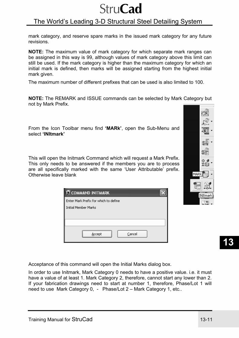
Training Manual for StruCad 13-11
The World’s Leading 3-D Structural Steel Detailing System
13
mark category, and reserve spare marks in the issued mark category for any future revisions.
NOTE: The maximum value of mark category for which separate mark ranges can be assigned in this way is 99, although values of mark category above this limit can still be used. If the mark category is higher than the maximum category for which an initial mark is defined, then marks will be assigned starting from the highest initial mark given. The maximum number of different prefixes that can be used is also limited to 100.
NOTE: The REMARK and ISSUE commands can be selected by Mark Category but not by Mark Prefix.
From the Icon Toolbar menu find ‘MARk’, open the Sub-Menu and select ‘INItmark’ This will open the Initmark Command which will request a Mark Prefix. This only needs to be answered if the members you are to process are all specifically marked with the same ‘User Attributable’ prefix. Otherwise leave blank
Acceptance of this command will open the Initial Marks dialog box. In order to use Initmark, Mark Category 0 needs to have a positive value. i.e. it must have a value of at least 1. Mark Category 2, therefore, cannot start any lower than 2. If your fabrication drawings need to start at number 1, therefore, Phase/Lot 1 will need to use Mark Category 0, - Phase/Lot 2 – Mark Category 1, etc..

13-12 Issuing Manual for StruCad
The World’s Leading 3-D Structural Steel Detailing System
Another way of using Initmark would be, as shown, If you needed your mark numbers to be distinguishable between phases or lots without using a prefix. In the example shown, Phase/Lot 1 has a mark category of 1 and the mark numbers will start at 100. Phase/Lot 2 has a mark category of 2 and the mark numbers will start at 200 Phase/Lot 3 has a mark category of 3 and the mark numbers will start at 300 In all cases, therefore, the first number of the mark number is the Phase/Lot number.
6) Adding User Attributes
User Attributes consist of 50 user-definable attributes. These are reserved for anything the user may need to define about members that cannot be derived from the solid model .
No. Title Usage 0 PHASE To tag members with a Phase/Lot ref. 1 PRELIM To identify material ref. nos. and link to fabrication details 2 DESC To add a description to the member 3 FINISH To denote the finish specification 4 PREFIX To add a prefix to the member mark 5 NOTES To generate a global note on drawings, from text files in the /notes directory of StruCad or locally in the model. 6 GADIMS To suppress dimensioning of the member on GAs . Valid entries are 1,2 and 3. 7 CAMBER To note member camber on the drawing 8 SHRINK To shrink the length of a member on its fab detail 9 SUFFIX To add a suffix to a member mark 10 -17 Free for users - see How to use User Attributes

Training Manual for StruCad 13-13
The World’s Leading 3-D Structural Steel Detailing System
13
18 HRAIL Used to control dimensioning and labels in handrail construction. Default=NULL. Any non-NULL entry is used as a label and forces dimensioning of whole rail or bend rather than of segments. 19 ASTYPE Assembly type (ie a template for producing an assembly drawing, at present the only valid entry is STAIR) 20 Free for users - see How to use User Attributes
21 EDNOTE files Reserved for filename in local notes directory, used by EDNOTE 22-39 Free for users - see How to use User Attributes 40 Reserved for use by AceCad 41 WEIGHT Model default weight calculation 42 AREA Model default area calculation 43-49 Reserved for use by AceCad
Free User Attributes The following user attributes can be applied at any of the free USR numbers: PRECAMBER, NOTES1 to NOTES5, EXIST, ASSPAR and FABPAR Attributes 41 and 42 are reserved for WEIGHT and AREA, which are used to overwrite model default weight and area calculation options for particular members.
How to use User Attributes Attributes are added to members by the use of the ‘EDUsr’ command which allows members to be edited individually or, groups of members which share the same user attribute values may be edited at the same time. When the EDUsr command is invoked, you are presented with a table of attributes to fill in with the values required. If you need to delete a value for a User Attribute, enter the value “null”. What Each User Attribute Does USER 0 (PHASE)
User 0 is used to apply a Phase Number to selected members. i. Select the EDUsr command and choose the PHASE option. ii. Then type in the phase no. you wish to apply, eg 1, 2, etc. iii. Finally select the members to which you wish to apply this phase. USER 1 (PRELIM)
User 1 is used to apply a Prelim Number (ie a material take-off number) to selected members. Each wireframe member can have these numbers applied at a very early stage of the contract by use of the TRANSMARK command. This Prelim No. will always remain with the member so that, at the end of the contract, the member (and its shop drawing) can be referenced back to its original Prelim No.

13-14 Issuing Manual for StruCad
The World’s Leading 3-D Structural Steel Detailing System
USER 2 (DESCRIPTION)
User 2 is used to apply a Description of a particular member or section to selected members. i. Select the EDUsr command and choose the DESCRIPTION option. ii. Type in the description you want to apply, eg BRACE iii. Then select the members to which you wish to apply this description. USER 3 (FINISH)
User 3 is used to describe the finish that will be applied to the selected members. i. Select the EDUsr command and choose the FINISH option. ii. Then type in the finish that you want to be applied, eg SA2.5 iii. Finally select to which members you want to apply this finish. USER 4 (PREFIX)
User 4 is used to apply prefix letters to the identification numbers of selected members. For example, you may want to prefix all of the columns with the letter CLM, to differentiate them from cleats.
NOTE: User attributes cannot be applied to fittings. i. Select the EDUsr command and choose the PREFIX option. ii. Type in the PREFIX you wish to apply, eg CLM. iii. Then select the members to which you want to apply this prefix. The prefix attribute, when applied to a member, will be shown on its fabrication detail in front of both its mark and drawing number. It is suggested that, if prefixes are used, they also be set as a criteria for member marking. Thus if members have null or different prefixes they will not be given the same mark. USER 5 (NOTES)
Attribute User 5 is used to apply one NOTE to the members selected. For example, you may want to have a note ‘TOP FLANGE UNPAINTED’ beside some floor beams, or one denoting “ALL WELDS TO BE TESTED TO BS5950” on a particular Fabrication Drawing.
NOTE: Although long notes can be added to member fabrication details by use of this “notes” attribute, for a short note, or for a number of separate notes, you can use the EDNOTE command to allocate up to 5 notes to a member. User Attribute 5 is more useful for longer notes. Before you can apply a note, you must first create it using a text editor such as NOTEPAD, and then save it in the strucad\notes directory. Proceed as follows: i. First create a new text file, eg
PLEASE NOTE. - ALL WELDS TO BE TESTED TO BS5950.

Training Manual for StruCad 13-15
The World’s Leading 3-D Structural Steel Detailing System
13
ii. Save the file by scrolling to either the global notes directory in StruCad v??/strucad, (or your model’s local notes directory), and then name your file - for example, strucad\notes\weld.txt. The attribute/file name prefix can be up to 10 characters long, and the .txt extension must be added.
NOTE: If you need to put your notes in a directory other than “notes”, use MODPar, “Setup & Layout” and “Pathname to Notes Files” options to change it from the default “notes”. iii. Now select the EDUsr command and select the member(s) to which you wish to apply this note. iv. Finally, choose the NOTES option and type in the name of the note file that you wish to apply, without its .txt extension. So, for the above example, you would type in “weld”.
Long notes can be added to member fabrication details by use of this “notes” attribute. Suppose we have created a text file called “weld6.txt” and used MODPar to defined the location of the directory that contains it: ************************************************* WELDING NOTES - CONTINUOUS UNO * * RAFTER EAVES: * RAFTER AND HAUNCH FLANGE TO ENDPLATE 8mm FW * RAFTER AND HAUNCH WEB TO ENDPLATE 6mm FW * HAUNCH FLANGE TO RAFTER FLANGE 8mm FW * HAUNCH WEB TO RAFTER FLANGE 6mm FW INTERMITTENT * (300 HIT 300 MISS). * * RAFTER APEX: * ALL WELDS 6mm FW * * ************************************************* If we then add a note attribute ‘weld6’ to a selected wireframe member, this note will then appear on the fabrication detail after we have UPDATED the model and done a FABMEM on the member. USER 6 (GADIMS)
User Attribute 6 determines which members are to be dimensioned on GA drawings, and how that dimensioning should be done. As an example, for the sake of clarity, you may not wish to dimension bracings on your arrangement drawings. i. Select the EDUsr command and choose the GADIMS option. ii. There are three options from which to choose:

13-16 Issuing Manual for StruCad
The World’s Leading 3-D Structural Steel Detailing System
GADIMS 1 - Members are fully dimensioned on GAs
GADIMS 2 - Members are dimensioned with their position/location only
GADIMS 3 - Members have no dimensions/locations Type in the GADIM No. you wish to apply, eg 3. iii. Then select the members to which you wish to apply this GADIM. So this could be used to ensure that no diagonal ties, sag bars or struts are dimensioned when you produce a GA showing cold rolled members, by applying 3 as the gadims user attribute to these members. This allows the user to have much more control over the dimensions provided on the layout. USER 7 (CAMBER) User 7 is a special attribute that is applied automatically by other StruCad commands such as TRUSS. It therefore requires no further input. USER 8 (SHRINK) User 8 is another special attribute that is applied automatically by StruCad commands such as TRUSS. It is automatically applied to assembly internals by the truss command for adjusting member lengths when a camber is involved. The actual member length is ‘shrunk’ by the value applied, ie if the member length was 2000 and it had a shrink value of 20, the length will now become 1980.
However, the Shrink attribute can also be applied manually. This attribute alters the fabrication drawings of selected members, making their dimensions shorter by a stipulated amount. For example, users sometimes have to make cross bracings shorter so that they will be in tension when erected. The shrink attribute will not change the actual wireframe member, but the detail drawing will be altered to give the new shortened dimensions. i. Select the EDUsr command and choose the SHRINK option. ii. Then type in the shrink that you wish to apply, eg 2 (2mm) iii. Finally select the members to which you wish to apply the shrink.
NOTE: This can also be applied as a negative number, thus making the relevant members in the detail drawings longer than they should be. OTHER USER ATTRIBUTES There are a number of other user attributes that can be allocated by PARAM to be in a “free” USER number, or which may already be allocated to a particular reserved USER number (as indicated here). So, for example, we have PRECAMBER, HRAIL (18), ASTYPE (19), EDNOTE (21 - used by the EDNOTE command), WEIGHT (42), AREA (43), EXIST, ASSPAR and FABPAR.
After applying your User Attributes, RUN THE UPDATE COMMAND. Remember to insert “null” if you need to delete an attribute’s value or name, then UPDATE again.

Training Manual for StruCad 13-17
The World’s Leading 3-D Structural Steel Detailing System
13
PRECAMBER Whichever free USER number is allocated to this is used to apply a Precamber to a member, and this information will be reflected on the fabrication drawings. As well as showing the required Precamber, it will also show the bevel that is required at each end of the beam. i. This attribute must first be added to the model parameters - using the PARAM command, go to any free user attribute (eg User 10) and change it name to PRECAMBER. ii. Select the EDUsr command, select the member(s) concerned, and choose the USER number allocated to Precamber. iii. Then type in the pre-camber that you wish to apply, eg 200 (200mm) iv. Select the members to which you wish to apply the pre-camber.
HRAIL Insert using PARAM. Any value other than “null” will use improved dimensioning on the drawings.
EXIST Insert using PARAM. Any value will force a dummy member with this attribute allocated to appear on GAs.
ASTYPE, WEIGHT and AREA These are reserved for use by StruCad commands, and should not be changed without first consulting AceCad.
ASSPAR and FABPAR The file name (without its extension) of a customised PAR file for a special member (straight or curved) or assembly can be given here. The file must be in %strucad%/par and must be different from the existing one (eg fadps1.par, identified as fadps1 here).
After applying your User Attributes, run the UPDATE command.
Editing Attributes by Group In order to speed up the process of adding user attributes, members may be edited in groups. i.e. To edit the ‘Description’ attribute. First set your Layers to, let us say, the Column layer and turn all other layers off.

13-18 Issuing Manual for StruCad
The World’s Leading 3-D Structural Steel Detailing System
From the Icon Toolbar menu, find, and select ‘EDUsr’
You will now be asked to select the members you wish to edit.
By depressing the right mouse button the selection menu will appear. Choose ‘Visible’ This will select all of the visible members, which are your columns. Confirm your selection by depressing the middle mouse button This will bring up a ‘User Attribute’ dialog box, which can then be edited
Against the ‘DESCRIPTION’ attribute you can now add the description of the member, in this case it is ‘Column’
All other descriptions can now be added in the same way.
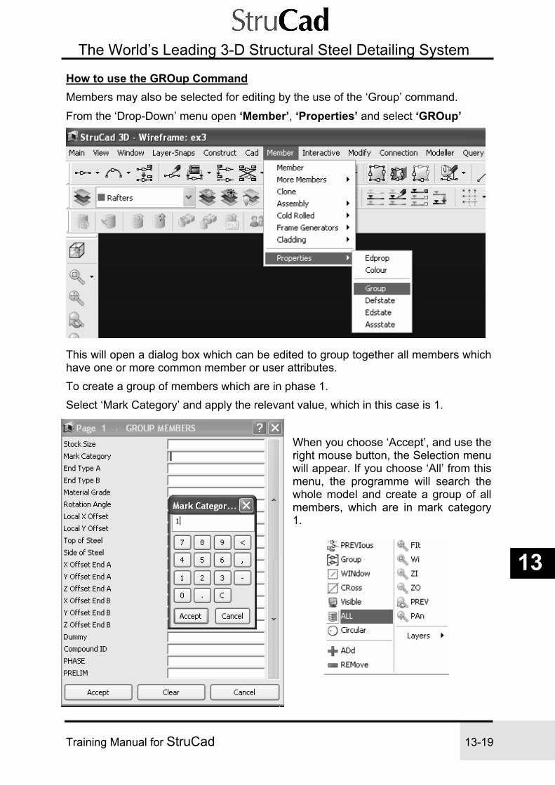
Training Manual for StruCad 13-19
The World’s Leading 3-D Structural Steel Detailing System
13
How to use the GROup Command Members may also be selected for editing by the use of the ‘Group’ command.
From the ‘Drop-Down’ menu open ‘Member’, ‘Properties’ and select ‘GROup’
This will open a dialog box which can be edited to group together all members which have one or more common member or user attributes. To create a group of members which are in phase 1. Select ‘Mark Category’ and apply the relevant value, which in this case is 1.
When you choose ‘Accept’, and use the right mouse button, the Selection menu will appear. If you choose ‘All’ from this menu, the programme will search the whole model and create a group of all members, which are in mark category 1.

13-20 Issuing Manual for StruCad
The World’s Leading 3-D Structural Steel Detailing System
Now we can add Attribute values using ‘Group’. i.e. To add the ‘Phase’ attribute.
From the Icon Toolbar menu, find, and select ‘EDUsr’
When you are asked to select the members you wish to edit, use the right mouse button to open the selection menu and choose the ‘Group’ option. Confirmation of the command with middle mouse button or ‘Enter’ will open the ‘User Attributes’ dialog box which can now be edited for ‘Phase’ with a value of 1.
The ‘Group’ command can be used to edit more attributes, as the group will remain ’Live’ until either a new group is created, the parameters of the group are changed or the session is ended.

Training Manual for StruCad 13-21
The World’s Leading 3-D Structural Steel Detailing System
13
Making Attributes Appear on Fabrication Drawings Many of the pre-set attributes will automatically appear on your fabrication drawings, Notes, Prefix, Suffix, Camber etc. but some, notably attributes 0,1,2,3 and any user created attributes will need to be added to drawings via the MODPar command.
How to use the MODPar Command The MODPar command allows you to customise some of the Base Drawing formats for your specific company or contracts. To do this, you create and modify the automatic Drawing Production System (DPS) parameters for the appropriate base drawings on-screen. You do not have to modify the par files directly.
The command is used to customise the base drawings used to output General Arrangements, Multi-member Assemblies, Fabrication Drawings, member Shaft Drawings and Fitting Details. The default parameter files associated with these programs are : General Arrangements (gaprod) gadps.par Multi-member Assemblies (autoass,fabass) asdps.par Fabrication Drawings (autofab,fabmem) fadps.par Member Shaft Drawings (autoshaft,shaftmem) shdps.par Fitting Drawings (autofit,fitmem) ftdps.par Parameters can be modified for the whole StruCad system (Globally) or for the particular currently active model (Local). When you invoke the command in the Wireframe environment, you get a series of menus that lead you through a set-up sequence appropriate to the base drawing that you choose. The MODPar command has its own context-sensitive help. As you work through the menus, use the HELP button to get overall descriptions of the activities. To get help on a particular parameter, click the ? button then click on the value box for the parameter. When you are finished, you select whether to file the new base drawing set-up as a global or local set-up file.
From the ‘Drop-Down’ menu open ‘Drawings’ and select ‘MODPar’

13-22 Issuing Manual for StruCad
The World’s Leading 3-D Structural Steel Detailing System
Select drawing category - FABRICATION DETAILS You will be asked to select a parameter file.
To change the file in StruCad choose Global fadps, To change the file in the current model choose Local fadps. To change the file for ‘Nested Drawings’, Global or Local, choose n_ fadps.
Select - Setup & Layout

Training Manual for StruCad 13-23
The World’s Leading 3-D Structural Steel Detailing System
13
In List User Attributes, list the appropriate reference numbers for all of the attributes that you want displayed on your fabrication drawings. i.e.:-
0 - for ‘Phase’, 1 - for ‘Prelim’, 2 - for ‘Description’ and 3 - for ‘Finish’
NOTE Each reference number is separated from the following number with a space.
7) The MATList Command
The MATList command generates the Material Lists for phases, lots or an entire StruCad model. A wide range of standard report formats are provided and you can select those required either from a user-defined default set-up list, or on an individual selection basis. In general terms, the standard reports will produce schedules of members and fittings by mark, section size, phase or user attribute, together with assembly and bolt lists. The information includes cutting lengths, weights and surface areas for individual items, and aggregated for each category. They thus provide the basic information, in addition to drawings, required to process contracts.
How to use the MATList Command When the MATList command is first invoked, information is automatically exported from the StruCad model to the material database. You must therefore ensure that the StruCad model is up-to-date before invoking MATList. On subsequent occasions, you will be given the option/reminder to re-export or not - you must

13-24 Issuing Manual for StruCad
The World’s Leading 3-D Structural Steel Detailing System
ensure that the data corresponds with the current StruCad model by re-exporting data at the appropriate times. In addition, note that previously-generated reports will be overwritten only when a new one is made with data that has been re-exported. So, it is possible, after modifying a model, to print reports that are out of date with the material database - you must therefore re-run all the reports you have run, on the re-exported data.
From the Icon Toolbar menu, find, and select ‘MATList’ On selecting the MATList command, you are given two options, which are described below:
"Run/Set-Up" will bring up the main MATList window.
Displayed will be a list of potentially available reports to generate. To select a report to generate simple check the box to the left of the report name. If you wish to first clear the default selection, click "Clear All". To generate all the reports click "Select All" - this will check all the reports available. If the selection you have chosen is used frequently, you can save it by clicking "Save Selection", and it becomes the new default.

Training Manual for StruCad 13-25
The World’s Leading 3-D Structural Steel Detailing System
13
Make your selection and click "Run Selected". This will open a table asking whether you wish to generate the reports by ‘Selected User Attribute’ or by ‘All Contract’. By choosing 'Selected User Attribute' you must select a user attribute between 0 and 49. On clicking OK the attribute values will be shown; choose PHASE and then click OK. You are then asked to select the value of that attribute, i.e. which phase are the reports to be produced for. Select 1, and ‘OK’, the reports for Phase 1 will then be generated and opened.

13-26 Issuing Manual for StruCad
The World’s Leading 3-D Structural Steel Detailing System
By selecting View - Set Screen/Printer Font, you can change the Screen and Printer font used to display or print the reports. The MATList command has been enhanced so that you can print reports that have just been produced at any printer, using the Windows interface.
By inspection of these lists you can now check for incorrect steel grades, missing user attributes and site free fittings etc.
To print a report whilst it is displayed in this MATList window, select File - Print ( or the Print button), and it will be printed at your network printer. To adjust the page set-up select File - Page Set-up. To preview the report as it will appear on the page, select File - Print Preview.
The second MATList command option is used to "Print/View" any of the existing reports, whether they have just been produced or not. If this option is selected, a list of all the reports that currently exist is displayed. From this list you can select the ones that you want to be printed or viewed - press the View Selected button if you just want to view them, or press Print to print them via StruCad’s printer.
8) The TALLY Command The TALLY command assigns specific user attributes to selected members, and tallies up the cumulative weight of these members, including their fittings, as they are selected. In particular, the TALLY command is most useful for "phasing" a StruCad model into erectable packages (eg 20 tonne lorry loads). However, you can actually tally up any user attribute.
How to use the TALLY Command
NOTE: The EDUsr command will be much faster for assigning other user attributes, or for assigning PHASE to a large number of members. The TALLY activity requires each member to be selected one at a time. Both TALLY and EDUsr achieve the same result, but TALLY can also allocate a colour to the user attribute. StruCad first checks that the model is fully marked, and that the model data is up-to-date. If not, you must select YES to either or both the prompts when they appear. When you start tallying, any existing members with the specified value of the chosen user attribute are weighed before selecting new members. The tallied weight is displayed on the status line at the top of the screen and the members are coloured according to the user attribute. The maximum cut-off weight can be specified and you will be warned when this limit is reached. Note that a member changes to the colour specified to confirm that it has been selected. If a selected member is re-selected it will revert to its original colour and become de-selected; the tallied weight will then decrease. If you select a member that already has a different value of that attribute, you are given the choice to ignore it or change it.

Training Manual for StruCad 13-27
The World’s Leading 3-D Structural Steel Detailing System
13
Continue to tally members until a satisfactory limit has been reached. So that you can see which members have no values defined for any user attribute value, they will have a default "user attribute colour" of white. It is important to understand that members can be coloured BOTH according to "layer" and to "user attribute" values. After using the TALLY command and applying colours to different user attribute values (eg PHASE A may be blue and PHASE B may be green), you can set the colour of the members back to their original colours as defined by their layer using COLUSR. At any time, you can toggle the colours between either of the two modes by using the COLUSR command. In addition, the SUMUSR command will produce a summary of the colours, weights and numbers of members for all values of a particular user attribute, and will give the total weight of the structure. Although you have a running tally of the accumulating weight at the top of the screen, you will also get a message when your pre-set cut-off weight is reached. You can then stop there, or continue to add or subtract members to adjust that load.
From the Icon Toolbar menu find ‘EDUsr’, open the Sub-Menu, select ‘TALly’
You will now be asked if you wish to re-export the StruCad data. If you are not sure that the data is current choose ‘Yes’
A ‘Data Feedback Window’ will open as the data is exported. This will show how many members are being processed, how many fittings, joints, bolt groups, etc. When the processing is completed, select ‘OK’

13-28 Issuing Manual for StruCad
The World’s Leading 3-D Structural Steel Detailing System
A ‘User Attributes’ selection list will now open. From this list select the attribute you want to tally the steel by. i.e. we will use phase.
The TALLY dialog box will now open for editing. Against ‘Value’ we insert the number of the phase we wish to tally, i.e. 1. For ‘Colour’, any colour, (except white), may be selected. The Cut Off Weight, (which is in Tonnes) may also be edited if the value is inappropriate.
The wireframe model will now be displayed with the selected phase (1) highlighted in the chosen colour and the remaining members in the wireframe, which have not yet been Tallied, coloured white. You may now add to or remove members from this phase in order to achieve the required load weight.

Training Manual for StruCad 13-29
The World’s Leading 3-D Structural Steel Detailing System
13
The model is now ready to hand over to the checker Strucad Checker - (advisory checks)
Size and position checks - using general arrangements or by displaying solid Connection check - using ENDSTAT and CHKCOMP Run Material Lists to check for incorrect steel grades, missing user attributes and site free fittings CLASH Check for any member clashes or bolt access problems STRUWALKER to view the model in ‘Virtual Reality’ Produce 3d-views for marking discrepancies.

13-30 Issuing Manual for StruCad
The World’s Leading 3-D Structural Steel Detailing System
NOTES

Issuing Manual for StruCad 14-1
The World’s Leading 3-D Structural Steel Detailing System
14
StruCad Issuing Procedure
Section 2 – Issuing and Revision Control
1. Take a WCad from working model, this will become your issue model 2. Create Fabrication Drawings by running Autofab/Fabmem. (this will also mark the model for you)
3. Plot all drawings on A3 4. Check all drawings for obvious mistakes e.g. flying fittings, bolt group problems etc 5. Rectify any problems in the model 6. Run Autofab/Fabmem again, this will reproduce drawings of any changed items
7. Plot out any new drawings and throw away drawings of any deleted items 8. Plot out A1 drawings 9. Carry out the above procedure for autoass and autofit 10. Produce any required material lists 11. Run cam data if required 12. Transmark the model to a user attribute 13. Run the issue command

14-2 Issuing Manual for StruCad
The World’s Leading 3-D Structural Steel Detailing System
Creating an ‘ISSUE’ Model
It is advisable to create an ‘Issue’ model, especially if you are issuing the contract in ‘Phases’ or ‘Lots’. This will keep the working model and issued members separate until each phase or lot is complete.
1) The WCad Command The WCad command allows you to export StruCad entities out of a StruCad model or drawing to create a new StruCad "CAD database". The newly created model or drawing can then be accessed and manipulated like any other StruCad model or drawing. This command is usually used for transferring wireframe geometry between StruCad models in order to tidy up an existing model's database. (see below.) The WCad and RCad commands only process the "CAD database" and not the StruCad solid model database. Therefore the commands UPDATE, MODMEM, etc will need to be executed to create solid geometry of its members and connections. The WCad command behaves slightly differently in 3D Modelling and 2D Drawing. In 3D Modelling, WCad is used to make a copy of part or all of the wireframe structure of the current StruCad model, whereas in 2D Drawing, WCad is used to make a copy of part of a drawing. The newly-created model or drawing can then be manipulated and edited in its own right, or imported into another one using RCad.
NOTE: The command RCad can read and import any StruCad "CAD database" into the current StruCad model, including a database created by the WCad command.
How to use the WCad Command NB: When you WCad an existing model, the members will all be remarked differently when you update it. It should therefore not be used after an issue has been carried out. When a solid model has already been created (using MODEL or UPDATE), all the relevant directories, macro set-up files and interactive library files that are applicable to the model, can be copied across by using the "All Directories" option (this includes all your local .lib, .dat, .cat, .shp, .mac files, etc, but NOT things like CAD pointers and mark numbers). Only select "All Directories" = NO if no modelling has been done yet, or if you don't want to overwrite the destination model's local files. The WCad command gives you the option of processing the entire model, or only selected entities. You then provide a new model name, and a short but meaningful description for the particular sub-model or contract. A new model will be created containing the members, grids, levels, layers, construction entities, etc from the current wireframe model or drawing. WCad can also be used to tidy up (and thus reduce the size of) the database of an old model - but remember it could result in remarking. Simply WCad the whole model out under a new name, retaining "All Directories" (i.e. YES). Then RCad it into a fresh empty model. When you are satisfied that the model is OK, you can delete the old model and give the new one the original name.

Issuing Manual for StruCad 14-3
The World’s Leading 3-D Structural Steel Detailing System
14
NOTES: i). The date of creation for the WCad elements of such a "new" model will be that of the original model; it can be changed to the current date by editing the model parameters using PARAM.
ii). If you use WCad in the 3D environment to copy the wireframe structure of a whole model, the drawings are NOT copied with it, even when you copy ALL DIRECTORIES. You must use WCad again in the Drawing environment if you want to copy these.
Creating a WCad Copy From the ‘Drop-Down’ menu open ‘Utility’, ‘Export’ and select ‘WCad’
When dialog box opens:- from the ‘All/Select’ option Choose ‘ALL’, give the Model a new name/number, add a description.(remember that this description will be the ‘project’ information on drawings) and choose ‘Yes’ for ‘All Directories’ When you now select ‘Accept’ you will be asked for an ’Insertion Base Point’ and offered 0.0,0.0,0.0 by the prompt. If you accept this point, either by using the middle mouse button or the ’Enter’ key, the WCad will be created. Exit and save the working model and load the new WCad ‘Issue’ model and run UPDATE.

14-4 Issuing Manual for StruCad
The World’s Leading 3-D Structural Steel Detailing System
2) Create Fabrication Drawings. Fabrication Drawings may be created in two different ways, depending whether you wish to create the details for the whole model, or only for part of the model. I.e. for a lot or phase.
To create drawings for the whole model we will use the AUTOFAb command, or to create drawings for a selected part of the model we will use the FABMEm command.
The AUTOFAb Command The AUTOFAb command automatically produces fabrication detail drawings for every member in the StruCad model.
How to use the AUTOFAb Command
NOTE: Before members can be processed by AUTOFAb the model must first be modelled by UPDATE, MODMEM, MODCALC or MODASS. When AUTOFAb is selected, the fabrication drawings are produced according to the default parameters set up in the "fadps.par" file contained in the model directory; to change these you need to use the MODPAR command. The program will automatically select the most suitable drawing sheet size for the detail from the user-defined drawing library.
NOTE: The drawing number will be the same as the mark number of the member on that drawing. AUTOFAb will automatically update all fabrication drawings, in order to be synchronised with the StruCad model. Any drawings remaining for members which no longer exist will be automatically deleted.
Revision control is achieved by use of the ISSUE command. When the ISSUE command is invoked, the member and its fitting details and quantities are compared with those at the time of the previous ISSUE of the drawing. If changes have occurred, the revision letter will be incremented and it will be shown on the drawing together with the issue date and the time the revised drawing was produced. However, AUTOFAb will produce a new drawing for members if changes have taken place, but the revision letter and ISSUE date shown will be those of the last ISSUE.
From the Icon Toolbar menu find ‘AUTOFAb’
The program will automatically mark the model (if required) and, when marking is complete, create fabrication drawings for the whole model.

Issuing Manual for StruCad 14-5
The World’s Leading 3-D Structural Steel Detailing System
14
The FABMEm Command
The FABMEm command produces fabrication detail drawings for specifically selected members. It is particularly useful in the early stages of a contract when "sample details" are required for typical members. Used in conjunction with MODMEM, you can model just certain areas of a structure and then produce selective details for some of those modelled members.
How to use the FABMEm Command NOTE: Before members can be processed by FABMEm the model must first be modelled by UPDATE, MODMEM, MODCALC or MODASS. Then initiate the FABMEm command and select the members for which you want Fabrication Drawings produced.
Revision control is achieved by use of the ISSUE command. When the ISSUE command is invoked, member and fitting details and quantities are compared with those at the time of the previous ISSUE. If changes have occurred, the revision letter will be incremented, and it will be shown on the drawing together with the issue date and the time that the revised drawing was produced.
NOTE: Revision letters are not incremented other than by use of the ISSUE command. Thus, when FABMEm produces a new drawing for members, the revision letter and issue date shown will be those of the last formal issue.
The base drawings from which your Fabrication Drawings are produced can be customised to suit your company or the country that you are in. The automatic production of the Fabrication Drawings by StruCad is controlled by drawing parameters; to change these you need to use the MODPAR command.
From the Icon Toolbar menu find ‘AUTOFAb’, select the ‘Sub – Menu’, and then select ‘FABMEm’ The program will ask you to select members. This can be done either by selecting members on an individual basis, by using the ‘Group’ command as described in section 1, or by selecting ‘visible’ members (when other members have been switched off) from the ‘Select Objects’ menu which may be accessed with the right mouse button.

14-6 Issuing Manual for StruCad
The World’s Leading 3-D Structural Steel Detailing System
The MODPAR Command The MODPAR command allows you to customise some of the Base Drawing formats for your specific company or contracts. To do this, you create and modify the automatic Drawing Production System (DPS) parameters for the appropriate base drawings on-screen. You do not have to modify the par files directly.
The command is used to customise the base drawings used to output General Arrangements, Multi-member Assemblies, Fabrication Drawings, member Shaft Drawings and Fitting Details.
How to use the MODPAR Command The command can be used for General Arrangements, Multi-member Assemblies, Fabrication and Fitting Drawings. The default parameter files associated with these programs are : General Arrangements (gaprod) gadps.par Multi-member Assemblies (autoass,fabass) asdps.par Fabrication Drawings (autofab,fabmem) fadps.par Member Shaft Drawings (autoshaft,shaftmem) shdps.par Fitting Drawings (autofit,fitmem) ftdps.par Parameters can be modified for the whole StruCad system (Globally) or for the particular currently active model (Local). When you invoke the command in the Wireframe environment, you get a series of menus that lead you through a set-up sequence appropriate to the base drawing that you choose. The MODPAR command has its own context-sensitive help. As you work through the menus, use the HELP button to get overall descriptions of the activities. To get help on a particular parameter, click the ? button then click on the value box for the parameter. When you are finished, you select whether to file the new base drawing set-up as a global or local set-up file.
From the ‘Drop-Down’ menu open ‘Drawings’ and select ‘MODPar’
Select – ‘Fabrication Details’

Issuing Manual for StruCad 14-7
The World’s Leading 3-D Structural Steel Detailing System
14
To modify the model Parameters in StruCad select Global fadps, this will set the parameters for all future models. To set the Parameters only for this model, select Local fadps. To modify the model Parameters for ‘Nested Drawings’, Global or Local, choose n_ fadps
3) Printing Fabrication Drawings. When the drawing production program is finished, drawings may be accessed in different ways. By using the ‘Viewdraw’ and Fabdraw’ commands from the wire frame, drawings may be accessed and printed on an individual basis. However if you wish to print a number of drawings together, as we do now, then we need to access the StruCad drawing environment.
The StruCad Drawing Environment may be accessed direct from the wireframe model by depressing the ‘F2’ key on the keyboard, or, from the Strucad Workspace by selecting the ‘Drawings’ button whilst the correct model is highlighted in the work folder.

14-8 Issuing Manual for StruCad
The World’s Leading 3-D Structural Steel Detailing System
Either option will open the ‘StruCad 2D Drawing Explorer’ which shows all of the StruCad drawing categories available, and the number of drawings in each category which have been created to date.
From this explorer you can select ‘Fabrication Details’ which will then open to show the fabrication drawings listed in numerical order. These drawings can now be selected for ‘Batch Plotting/Printing’ Drawings are selected by picking with the left mouse button. To select drawings on an indivdual basis, i.e. not a continuous list, hold the control key down and select the drawings one at a time. Alternatively, if you wish to select all drawings or, a list of drawings with no breaks, first select the top drawing, hold down the shift key, and select the bottom drawing, both drawings, together with all of the intermediate drawings will be highlighted and selected.

Issuing Manual for StruCad 14-9
The World’s Leading 3-D Structural Steel Detailing System
14
Now place the curser over any highlighted drawing and depress right mouse button. This will open an options box which displays all the options available. By selecting ‘Print’ you will open a ‘Plot’ box which will list all the plotter and printer options which are currently available for use, select the option you require, in this case we will use an ‘A3’ printer. You will then be aked to ‘queue plot’ accept ‘yes’ and drawings will be printed from the selected printer.

14-10 Issuing Manual for StruCad
The World’s Leading 3-D Structural Steel Detailing System
4) Checking Fabrication Drawings. When the drawings have been printed they can be checked for mistakes, such as ’flying fittings’ and bolt group problems.
5) Rectify Model When the drawings have been checked any problems which are found can be rectified in the ‘wireframe’ model.
6) Run Autofab/Fabmem again After rectification of the model the changed drawings need to be produced. If the original drawings were run using Autofab, then run Autofab again and the drawings will be automatically changed. Drawings which require no change will be ignored and any drawings which are no longer required will be deleted.If the original drawings were run using Fabmem, then either delete the original drawings and run fabmem again or, run fabmem only for the members which have been changed. Running Fabmem WILL NOT automatically remove drawings which are no longer required, any such drawings will need to be deleted manually so please be aware of this.
7) Replace Changed Drawings Those drawings which have changed will now need to be printed and the original details, which are now incorrect, will need to be destroyed.
8) Plot any A1 Drawings which are required Although StruCad may have placed some of your fabrication drawings on A2 or A1 formats, they may be perfectly readable as you have printed them, on A3. If however some are not suitable on A3, these will need to be re-printed in A1 format.
9) Assembly Drawings and Fitting Details. Assembly drawings can now be produced using either Autoass, which will select all assemblies in the model, or Fabass where assemblies will need to be selected manually. Fitting drawings may now be produced by using either Autofit or Fitmem . Assembly drawings should be plotted to A1/A2 etc as required and fitting details printed to A4.
10) Produce Material Lists Any material lists which are required with the steel issue may now be run. Typically a ‘Phase’ or ‘Lot’ may include the following lists.
1) A ’Hot Rolled Member by Mark’ list (hrmemmrk), 2) A ‘Hot Rolled Shop Fittings by Mark’ list (hrshpfit) 3) A ‘Site Bolt Summary – Hot Rolled’ (hrsitblt)

Issuing Manual for StruCad 14-11
The World’s Leading 3-D Structural Steel Detailing System
14
NOTE; These lists are only an example of what might be required. Each Company will have different requirements, so please look through the lists available to determine which ones are applicable.
11) Produce CAM Data (where required) For steel manufacturers who operate CNC machinery, the AUTOCam command may be used to automatically extract Computer Aided Manufacturing Data for all members and fittings in the StruCad model. The data produced is in AceCad's own neutral CAM data format. This data may then be converted by one of AceCad's post-processors into data to be sent to a particular CNC machine. Alternatively, users or 3rd parties may develop their own post-processors to interpret the CAM data.
When the AUTOCam command is initiated, StruCam automatically produces CAM data for the whole model.
NOTE: If only particular members and their associated fittings require to be processed, the CAMem command should be used, since this can selectively produce the required CAM data.
From the Icon Toolbar menu find ‘AUTOCam’
The program will then automatically mark the model, (if required) and run the hot rolled cam data for the whole model. (If you have chosen to run your cam data via CAMem then you will need to select the members to process.)
From the Icon Toolbar menu find ‘AUTOCam’, select the ‘Sub – Menu’, and then select ‘CAMem’
Post Processing (where applicable) After producing the neutral CAM data using AUTOCam or CAMem, the data may be post-processed to a particular machine type. To do this, proceed as follows: Go to the StruCad Drawings environment, either via the F2 ‘Hot Key’ or from the front end of StruCad. This will open the ‘StruCad 2D Drawing Explorer’, which shows all of the StruCad drawing categories available, and also shows the CAM Categories with Member Details and Fitting Details

14-12 Issuing Manual for StruCad
The World’s Leading 3-D Structural Steel Detailing System
From this explorer you can select ‘Member Details’ which will then open to show the Cam Data drawings listed in numerical order.

Issuing Manual for StruCad 14-13
The World’s Leading 3-D Structural Steel Detailing System
14
These drawings may now be selected for ‘Downloading’, and are selected by picking with the left mouse button. To select drawings on an indivdual basis, i.e. not a continuous list, hold the control key down and select the drawings one at a time. Alternatively, if you wish to select all drawings or, a list of drawings with no breaks, first select the top drawing, hold down the shift key, and select the bottom drawing, both drawings, together with all of the intermediate drawings will be highlighted and selected. Now place the curser over any highlighted drawing and depress right mouse button. This will open an options box which displays all the options available, one of which is ‘Download’. By selecting ‘Download’ you will open a ‘Download CNC Data’ box which will list all the CNC Machine Language options which are currently available for use. Now select the option you require, in this case we have chosen ‘DSTV Standard’. You will then need to enter the name of a sub-folder, this can be any alphanumeric name you like. If you are running AUTOCam you could use the model name, as the data is for the whole model, however, if you are running CAMem because the model is split into phases then the phase name could be used.
Data from these directories should be copied to the required data directory on the PC operating the CNC machine. These files can be copied over your network, sent by e-mail direct to the actual CNC machines at the fabrication company. For example, data for a TDK1000 machine is generated using the TDK1000 post-processor, which creates Peddimat files in the sub-directory ...\model\tdk1000. These files are in the same format as data files typed directly into a Peddimat machine, and so can be viewed and edited on the Peddimat system.

14-14 Issuing Manual for StruCad
The World’s Leading 3-D Structural Steel Detailing System
Format of the Data StruCad generates Peddimat data files in the same format as for manually programmed pieces prior to the generation and output of the piece programs. The data is stored within the model directory as follows: <workdirectory>\<model>\<ppname>\<batch> where: <workdirectory> is the path to your work directory <model> model name <batch> batch name as specified as ‘MS-DOS Directory Name’ above <ppname> post-processor name such as ‘pedditdk’ or ‘tdk1000’
Some CNC software systems allow the user to specify the source directory for the data file, while others have a very specific and rigid structure. For example, in the Peddimat 2000 system, the data files are stored as: C:\pedorder\<batch> where: <batch> the batch name for StruCad as above, or Job No for a manually-programmed contract This process can be repeated as many times as required and if different names are given then a archive of all files is always available within the model.
12) Transmark the model to a User Attribute The TRANSMARK Command The TRANSMARK command is used to transfer member erection marks into particular user attributes of the selected members. It is particularly useful to rapidly allocate the current marks as PRELIM numbers to members at the time material is ordered. As the model progresses, it will then be possible to compare the new material requirements for any members with the material that was allocated to them at the PRELIM stage. It is also useful to allocate the current erection mark to a user attribute, at the time of issue, in order to keep a record of those marks in the event of a revision causing a change that alters the original marks; it is for this reason we are using Transmark.
How to use the TRANSMARK Command
After selecting the Transmark command you will be prompted to select members to be included in the transfer, choose ‘All’ from the list of options. You will then be prompted to select the User Attribute into which the marks are to be imported. This may be any of the unassigned and available attributes, I suggest you might choose attribute ‘12’. You will then be asked to confirm this request and warned about over-writing existing user attributes whether or not they have any values already.

Issuing Manual for StruCad 14-15
The World’s Leading 3-D Structural Steel Detailing System
14
Use LABUSR if you need to check. The results of the transfer can be checked using LABUSR or ULIST. Attribute 12 may be displayed automatically on your fabrication drawings by adding the chosen attribute number to those already listed in the ‘setup and layout’ file of the fadps parameter files for fabrication drawings which are accessed via the MODPAR command. Attribute 12 may also be given a description by editing the model parameter files ( found in ‘Settings’ and ‘Param’ in the main menu.).
When ‘param’ is opened find attribute 12 and edit the word ’Null’ to read ‘First_Mark’ or some other suitable name. n.b.Note the underscore between words, - Do Not use Spaces. This name, together with its value, will then be displayed on all subsequent fabrication drawings.
13) Run the Issue Command. The ISSUE Command The ISSUE command is used, in the Wireframe environment, to create a new formal issue number corresponding to a new release of fabrication details, fitting details, general arrangement drawings and material lists.
How to use the ISSUE Command The main purpose of ISSUE is to enable changes to a drawing to be monitored when they have occurred between issues. This command is only intended to be used when a set of drawings is to be formally issued outside of the drawing office.
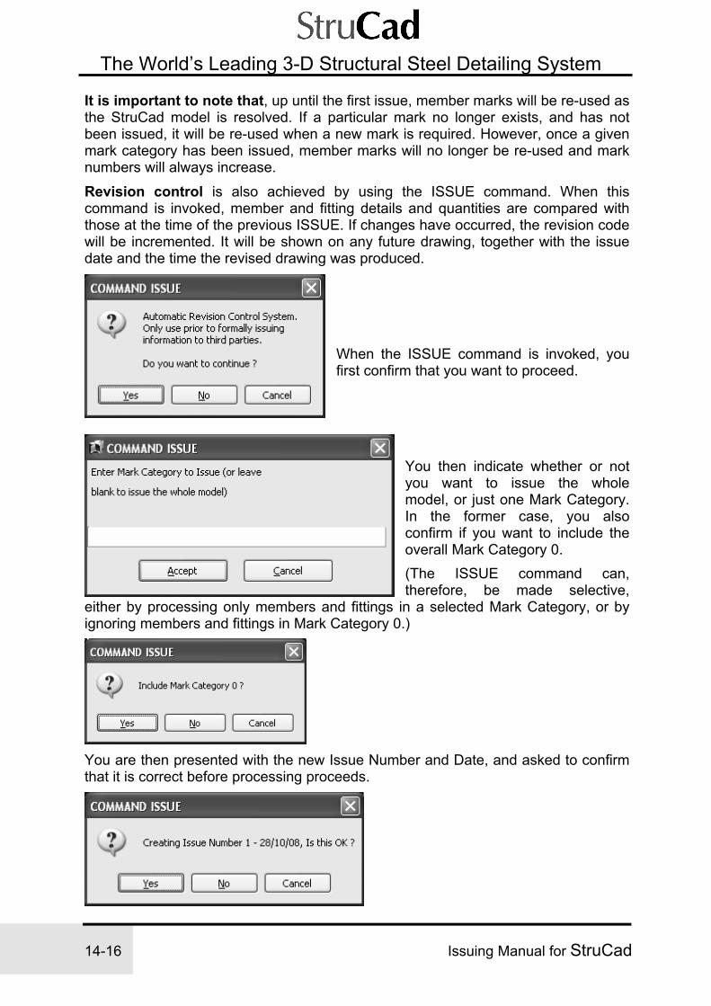
14-16 Issuing Manual for StruCad
The World’s Leading 3-D Structural Steel Detailing System
It is important to note that, up until the first issue, member marks will be re-used as the StruCad model is resolved. If a particular mark no longer exists, and has not been issued, it will be re-used when a new mark is required. However, once a given mark category has been issued, member marks will no longer be re-used and mark numbers will always increase.
Revision control is also achieved by using the ISSUE command. When this command is invoked, member and fitting details and quantities are compared with those at the time of the previous ISSUE. If changes have occurred, the revision code will be incremented. It will be shown on any future drawing, together with the issue date and the time the revised drawing was produced.
When the ISSUE command is invoked, you first confirm that you want to proceed.
You then indicate whether or not you want to issue the whole model, or just one Mark Category. In the former case, you also confirm if you want to include the overall Mark Category 0. (The ISSUE command can, therefore, be made selective,
either by processing only members and fittings in a selected Mark Category, or by ignoring members and fittings in Mark Category 0.)
You are then presented with the new Issue Number and Date, and asked to confirm that it is correct before processing proceeds.

Issuing Manual for StruCad 14-17
The World’s Leading 3-D Structural Steel Detailing System
14
The ‘Issue Command Wizard’ will now open and guide you through the issue procedure.
When the ISSUE command is executed on a model, two reports are produced, a revision report and a history report, listing the current members and fittings with their quantities. These may be viewed by selecting the appropriate button.

14-18 Issuing Manual for StruCad
The World’s Leading 3-D Structural Steel Detailing System
Typical Revision Report.
issueTypical History Report.

Issuing Manual for StruCad 14-19
The World’s Leading 3-D Structural Steel Detailing System
14
Subsequent ISSUES revise these reports and summarise the changes that have occurred since the previous ISSUE, in addition to adding the latest issue to the drawing registry. A complete history of all items on a contract is therefore available. Use the PRINT command to print out any revision reports or the contract history file (assuming that all drawings produced, and hence also the drawing registry, are up-to-date with the model detailed in the reports).
Select - ‘Finish’ to close the Issue report.

14-20 Issuing Manual for StruCad
The World’s Leading 3-D Structural Steel Detailing System
NOTES

Issuing Manual for StruCad 15-1
The World’s Leading 3-D Structural Steel Detailing System
15
StruCad Issuing Procedure
Section 3 – Creating a Drawing Package
Drawings and lists can be issued to Clients, Architects and Engineers quickly and easily by issuing an electronic ‘Package’ of those drawings and lists, which may then be read and/or printed using the free, re-distributable StruCad Drawing Viewer. Issuing drawings, in this manner, for approval, comment or fabrication, can save much valuable time. Using the same package it is also possible to issue 3D rendered ‘Virtual’ models, which may be viewed using the free, re-distributable StruWalker viewer.
Both StruCad Drawing Viewer and StruWalker may be downloaded from the AceCad website by going to www.acecad.co.uk and looking under Freeware on the Home page. There are two different ways of creating drawing packages; one is direct from StruCad Drawing Viewer, the other is via Drawing Explorer in the Drawings environment. Both options require the drawings, lists; struwalker files etc. to be created first, so make sure that all the information has been created before you begin to create the packages. We will look at both options, one at a time.
1. Creating a Drawing Package via StruCad Drawing Viewer.
2. Creating a Drawing Package via the 2D Drawing Explorer of the model.

15-2 Issuing Manual for StruCad
The World’s Leading 3-D Structural Steel Detailing System
1) Creating a Drawing Package via StruCad Drawing Viewer
From the prompt bar of the Start menu select the StruCad Drawing Viewer option from the Programs toolbar:
StruCad Drawing Viewer will now open.

Issuing Manual for StruCad 15-3
The World’s Leading 3-D Structural Steel Detailing System
15
StruCad Drawing Viewer will open, pointing at the last model to be opened by StruCad Drawing Viewer. If this is the model you wish to create your package from, you can display the Drawing Register by selecting; - View | Drawing Register from the Pull-Down Menu, by selecting the Drawing Register icon on the toolbar menu or by pressing the F2 shortcut key.
If, however, you wish to create your package from some other model, then the correct model needs to be opened.
• Open the Drawing files of the appropriate model for selection.
File - Open from Model (Select from drop-down menu)
Open the appropriate drive, StruCad V11, work directory and the required model.
The StruCad Drawing Register will open automatically

15-4 Issuing Manual for StruCad
The World’s Leading 3-D Structural Steel Detailing System
The Drawing Register displays all the standard StruCad Drawing Categories in a single dialogue box with eleven tabs, one for each category of drawings, plus one for Reports and one for Nested Fabrication Drawings. Another ‘Miscellaneous’ tab will appear later, which will carry other files, such as Struwalker .bsw files Each drawing category shows a slightly different set of columns for each drawing, but the first column is always the drawing name. This is always the same as the Mark for StruCad Fabrication and Assembly Drawings. The list can be sorted by any of the columns by clicking on the column header.
Creating the Package Close the StruCad Drawing Register, by selecting the ‘Close’ button at the bottom of the page.
File - Create Package (Select from drop-down menu)
This will create a ‘zpf’ (spf files in zipped format) folder in the model and asks for a file name. The zpf file can be given any suitable alphanumeric name.

Issuing Manual for StruCad 15-5
The World’s Leading 3-D Structural Steel Detailing System
15
If the ‘Open’ button is now selected the StruCad Drawing Register will return in a slightly modified format. Each drawing now has a selection box next to the mark number. For drawings to be included in the package, they need to be highlighted as shown. Drawings are selected for action by clicking anywhere in the row with the left mouse button. To select more than one drawing, select the first, hold down the SHIFT key and select the last of a continuous selection, or hold down the CONTROL key and individually select those drawings that are not in a continuous list. All selected drawings will highlight blue, as shown in the example below. When the selection is complete, select the ‘Add’ button and all boxes will be ‘ticked’

15-6 Issuing Manual for StruCad
The World’s Leading 3-D Structural Steel Detailing System
Repeat this procedure for each of the other drawing categories, and reports, until you have selected all of the documents you wish to send. Now check that what is included is correct. Any missing files can be added as before. Any files, which are not required, can be deleted by highlighting them, and selecting ‘Remove’. Now choose ‘Close’ to close the package.
Adding to the Package As well as drawings and reports, you can also add Struwalker (.bsw) files to your package. These files can then be read using the free, re-distributable, Struwalker and StruCad Drawing viewers. (see later)
File - Add to Package (Select from drop-down menu)
This will open a file selection window similar to the one shown below. Choose StruWalk and open.
This will open another selection window from which you may select from the Struwalker (.bsw) files, which were created during modelling. These files may be selected one at a time and added to the package by selecting the ‘open’ button.

Issuing Manual for StruCad 15-7
The World’s Leading 3-D Structural Steel Detailing System
15
Now you can check package to ensure that the StruWalker files are included.
File - Open (Select from drop-down menu)
Select the .zpf file that has just been created, and ‘Open’
Open the ‘Miscellaneous’ folder to check that your .bsw files are included.

15-8 Issuing Manual for StruCad
The World’s Leading 3-D Structural Steel Detailing System
When you are happy with the package, select ‘Close’. The package is now ready to send.
Sending the Package You may wish to attach this zip file to an e-mail as you would normally, or, alternatively, StruCad Drawing Viewer will attach it for you, as follows.
File - Send Mail (Select from drop-down menu) This will now create a new e-mail with the attachment added, ready for adding an address, subject and message.

Issuing Manual for StruCad 15-9
The World’s Leading 3-D Structural Steel Detailing System
15
2) Creating a Drawing Package via 2D Drawing Explorer From the StruCad Workspace select the appropriate model, and then select ‘Drawings’ from the toolbar.
Alternatively, if you are already in the 3D model, press the ‘F2’ key; this will take you directly to the drawings environment of the current model.
StruCad 2D Drawing Explorer will now open.

15-10 Issuing Manual for StruCad
The World’s Leading 3-D Structural Steel Detailing System
StruCad 2D Drawing Explorer will display a table of drawing categories, which shows the number of drawings currently being stored, and available, in each category.
Creating the Package
Open the appropriate drawing category, and select all drawings from this category, which you want to include in the package. Drawings are selected for inclusion by clicking anywhere in the row with the left mouse button. To select more than one drawing, select the first, hold down the SHIFT key and select the last of a continuous selection, or hold down the CONTROL key and individually select those drawings that are not in a continuous list. All selected drawings will highlight blue. When the drawings have been selected the ‘Icon Toolbar’ will become ‘Live’, this will allow you to select the ‘Package’ option, or, If more drawings are to be added from other categories, select the ‘Toggle Checks’ option.
Alternatively, place the mouse cursor over one of the highlighted drawings and depress the right mouse button. This will display an option box where you may select either the ‘Package’ option, or ‘Toggle Checks’, as required. Repeat this procedure for other Drawing Categories, which contain drawings that need to be packaged.
Note - If Reports and/or StruWalker files need to be added to this package, they cannot currently be added through StruCad 2D Drawing Explorer, they must be added using StruCad Drawing Viewer.
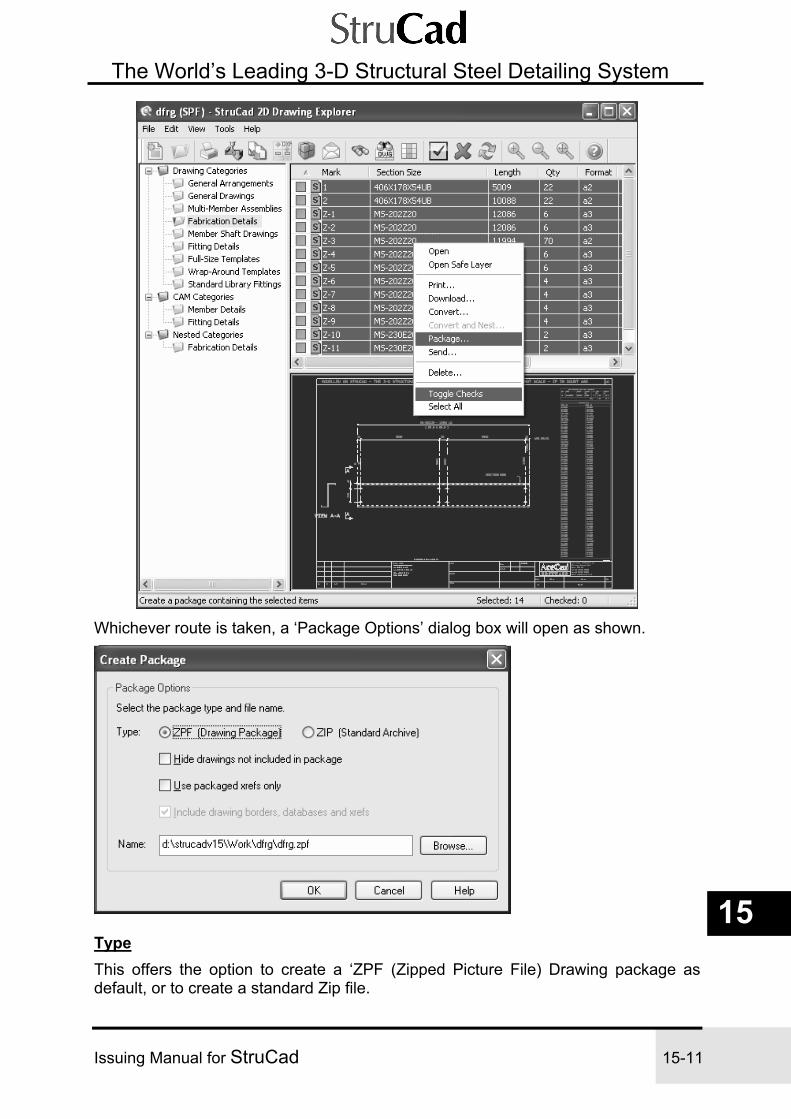
Issuing Manual for StruCad 15-11
The World’s Leading 3-D Structural Steel Detailing System
15
Whichever route is taken, a ‘Package Options’ dialog box will open as shown.
Type This offers the option to create a ‘ZPF (Zipped Picture File) Drawing package as default, or to create a standard Zip file.

15-12 Issuing Manual for StruCad
The World’s Leading 3-D Structural Steel Detailing System
Select the package type to send (ZPF or ZIP). For the ZPF format, the selected drawings are packaged together with the relevant base drawings, model parameters and drawing database files. The resulting drawing package is highly compressed, but allows the email recipient to assemble an exact copy of your local drawing environment. The package consists of just a single compressed file named by default, <model>.zpf. This ZPF file is fully compatible with StruCad’s re-distributable Drawing Viewer, and can also be manipulated with any utility that supports the standard ZIP file format (e.g. WinZip). A standard ZIP-format package can be sent as an alternative to ZPF. By default, the ZIP format does not contain any of the extra files associated with ZPF packages (e.g. base drawings, model parameters, etc.). Because of this, ZIP may be the preferred format when CAM data is packaged without drawings.
Hide drawings not included in package Select this check box to hide any drawings that have not been included in the package. By default, the re-distributable Drawing Viewer lists all drawings that are present in the model at the time the package is created. This option overrides the default behaviour and instructs the Drawing Viewer to list only drawings that are actually selected for packaging.
Use packaged xrefs only When you open a package that contains external references (xrefs) to files outside the current model, the re-distributable Drawing Viewer first tries to find the latest versions of the xrefs on your local computer or network environment. If you do not have local copies of these files, the Drawing Viewer will then use the packaged versions of the xrefs. This default behaviour can be overridden by selecting the “Use packaged xrefs only” check box. This option will force the Drawing Viewer to always use xrefs contained in the drawing package (i.e. it will not attempt to find xrefs, which may be out of date, on the computer where the package is opened).
Include drawing borders, databases and xrefs Select this check box to include drawing borders, databases and xrefs in a ZIP-format package. These additional files are automatically included in ZPF packages, but are not present by default in ZIP packages.
Name Enter the name of the package and the folder where it will be created. By default, a new package will be created in the current model path, called <model>.zpf. The file extension automatically changes to “.zip” when the ZIP package type is selected. To choose a different output folder, click the Browse button, or manually enter the full path name in the edit box provided.
Sending a Package (See the Send Option also) Having created your package, you may now wish to send it. When you click the OK button, a new email message is created via your system’s default mail application (e.g. Outlook). The drawing package is automatically added to the message as an

Issuing Manual for StruCad 15-13
The World’s Leading 3-D Structural Steel Detailing System
15
attachment. You can then select a recipient from your address book, write any accompanying text, and send the message in the usual way.
Package Formats
File Menu – The Package Option Select the File | Package menu option to display the Create Package dialog. This option allows you to create a compressed drawing “package” and save it as a file on your computer. (See the Send option for more information about the Create Package dialog).
File Menu – The Package Checked Option This menu option is similar to the File | Package option, but packages “checked” drawings (i.e. those indicated with a checkmark) that are part of the permanent selection set.
File Menu – The Send Option Select the File | Send menu option to display the Create Package dialog. This option allows you to create a compressed drawing “package” and send it via electronic mail. The selected drawings are packaged together with the relevant base drawings, model parameters and drawing database files. The resulting drawing package is highly compressed, but allows the email recipient to assemble an exact copy of your local drawing environment. These drawings may now be read and/or printed using the free, re-distributable StruCad Drawing Viewer.

15-14 Issuing Manual for StruCad
The World’s Leading 3-D Structural Steel Detailing System
NOTES


AceCad Software Ltd Truro House, Stephenson’s Way, Wyvern Business Park, Derby, DE21 6LY, United Kingdom
Tel: +44 (0) 1332 545800 Fax: +44 (0) 1332 545801 Email: [email protected] Web: www.acecad.co.uk
SGS-COC-005325
Printed on FSC Certified Paper