1 Supervisors Training Centre South Western Railway ...
411
1 Supervisors Training Centre South Western Railway Bangalore – 560023
-
Upload
khangminh22 -
Category
Documents
-
view
4 -
download
0
Transcript of 1 Supervisors Training Centre South Western Railway ...

1
Supervisors Training Centre South Western Railway
Bangalore – 560023

2
TABLE OF CONTENTS
1 ICF COACHES............................................................................4
1.1 INTRODUCTION ......................................................................4 1.2 ICF COACH SHELL / BODY................................................5 1.3 BOGIE ....................................................................................8 1.4 DRAW & BUFFING GEAR: .....................................................28 1.5 BRAKE RIGGING ...................................................................33 1.6 MAINTENANCE.....................................................................35 1.7 CORROSION AND ITS PREVENTION..............................91
2 LHB – COACHES .....................................................................98 2.1 INTRODUCTION TO LHB COACHES ........................................98 2.2 DESIGN FEATURES OF LHB COACHES .......................105 2.3 FIAT BOGIE. ....................................................................108 2.4 AIR BRAKE TESTING PROCEDURE FOR LHB COACHES: ........115
3 MODERN COACHES.............................................................123 3.1 DEMU COACHES ............................................................123 3.2 DOUBLE DECKER COACHES ................................................132
4 AIR BRAKE.............................................................................132 4.1 TYPES OF AIR BRAKE SYSTEM ............................................135 4.2 BOGIE MOUNTED BRAKE SYSTEM .............................161 4.3 DISTRIBUTOR VALVES.................................................175
5 WHEELS DEFECTS...............................................................191 6 ENVIRONMENTAL FRIENDLY TOILETS.........................206
6.1 CONTROLLED DISCHARGE TOILETS SYSTEM:.......................208 6.2 VACUUM TOILET SYSTEM...................................................211 6.3 ZERO DISCHARGE TOILET SYSTEM:.....................................214 6.4 AEROBIC TYPE BIOLOGICAL TOILET: ...................................216 6.5 IR-DRDO ANAEROBIC BIOLOGICAL TOILET SYSTEM: ..........217
7 FREIGHT STOCK ..................................................................227 7.2 MAINTENANCE PRACTICES FOR FREIGHT STOCK...253 7.3 JOINT PROCEDURE ORDER FOR FREIGHT TRAINS .................264 7.4 CASNUB BOGIES............................................................289

3
7.5 BLC WAGONS.................................................................301 7.6 SAB AND LOAD EMPTY BOX........................................310 7.7 TANK WAGONS..............................................................318
8 BRAKE POWER CALCULATIONS......................................327 8.1 BOGIE MOUNTED AC COACH: .............................................327 8.2 UNDERFRAME MOUNTED BRAKE SYSTEM (MODIFIED HORIZONTAL LEVER) AC COACH:....................................................329 8.3 PERCENTAGE OF BRAKING FOR THE BCN WAGON ...............333 8.4 BRAKE FORCE CALCULATION BY HAND BRAKE IN SLR.........336
9 BRAKE POWER RULES........................................................339 9.1 BRAKE POWER CERTIFICATE...............................................339
10 ISMD/ODC ..........................................................................346 11 BRAKE BINDING...............................................................348
11.1 CAUSES OF BRAKE BINDING: ...............................................348 12 COUPLINGS & TRAIN PARTING....................................354
12.1 COUPLINGS: .......................................................................354 12.2 TRAIN PARTING ..................................................................365
13 TRACK PARAMETERS.....................................................367 14 DISASTER MANAGEMENT .............................................371 15 INDIAN RAILWAY CONFERENCE ASSOCIATION (IRCA) 381
15.2 CHAPTERS ......................................................................384 16 IN-MOTION ELECTRONIC WEIGHING SYSTEM .......390 17 MATERIAL MANAGEMENT ...........................................405

4
1 ICF COACHES
1.1 Introduction
An attempt for standardisation of manufacturing of passenger coaches led to development of IRS design of steel body coaches. In 1954 Steel body coach design was taken from M/S Schlieren Switzerland for manufacturing of ICF Coaches at Perambur. Initially original speed of ICF coach was 96 kmph since secondary suspension was laminated spring. The design was modified to all coil bogies with longer suspension hanger and weight transfer through side bearers, thereby enabling speed potential to 105 kmph on mainline coaches and gradually enhanced to 140 kmph for Shatabdi, Rajadhani and Janshatabdi coaches. as per RDSO report No CWI Vol 1 Initial coaches manufactured were with Vacuum brake and later modified into twin pipe graduated release air brake system - under frame mounted. Due to frequent failure of SAB and heavy vibrations of pull rod this was further modified into Bogie Mounted Brake System. Brake rigging pins were reduced from 104 Nos to 82 Nos. Drawbar capacity is enhanced from 36t to 75t. The Codal life of ICF coaches of normal utilisation coaches is 25 years and light utilisation coaches are 40 years. Dimensions of Coach Description Dimension Length Over Buffer 22296 mm Length Over Head Stock 21336 mm Width 3245 mm Height From Rail Level 3886 mm (old), 4025 mm (new) Codal Life 25 Years

5
1.2 ICF COACH SHELL / BODY
Construction of coach body which forms big tubular hollow construction which is light in weight.
1.2.1 Salient Features of ICF Coach Shell / Body
All Metal: - ICF coach shell is made up of steel channel frames of thin sections except the seats & luggage racks which are made up of wooden members. Light Weight:-The weight of coach shell is reduced due to minimal use of wooden members, use of anti corrosive Corten Steel (IRSM 41) of thickness 1.6 mm for roof and 2 mm thickness

6
for corrugated floor, side panel and end panels during fabrication of coach body. The use of gusset plate, knee & rivets are also avoided in under frame. Hence weight of ICF shell is reduced by 26% to 32% compared to IRS coach shell which was used in the past. Integral Construction:-The shell of ICF coach is formed by welding together body side pillars, roof carlines, waist rail, light rail, cant rail & sole bar. Corrugated flooring, side panels, end panels & roof are welded together by means of homogenous welding. End pillars, stanchions and side pillars are also connected with paneling work. This type of structure gives the integral Anti telescopic construction:-The shell of ICF Coach is designed to bear 45 tones of vertical load and 200 tones of longitudinal impact on side buffers. The coach body is so designed that it is more strong at end portion as well as in passenger seating portion and less at the doorway and toilet. Due to which maximum kinetic energy during accident is absorbed by the end portion and get damaged and balance kinetic energy is also shared by the corrugated flooring and other members of body shell, resulting in keeping the passenger accommodation area of middle portion of shell safe with minimum damage. As a result of these properties, telescoping of one coach into adjacent coach is avoided during accident. Hence the above type of shell construction is known as anti telescopic construction. Stressed Skin Construction:- During the construction the side panel is welded to side pillars, waist rail, light rail and cant rail by means of CO2 welding which results in accumulation of stress in the panel. The stress is relieved by spot welding on the panels at different location after completion of the construction. 70 % of total developed stresses are absorbed by corrugated trough flooring. Thus this multi point welding property of the end & side panel is enough to minimize developed stresses of panels. Aerodynamic shell: - The shell is constructed with the curved roof at the corners and curved turn under to minimise the air resistance during the run of the coach at high speeds Anti corrosive:-To achieve anti corrosive property to the shell, Corten steel IRSM - 41 (max at turn under and lavatory portions) is

7
being utilized for paneling purpose. During manufacturing the process of sand blasting, grit blasting is also given on panel sheet which is helpful to prepare rough surface for painting resulting in less chances of corrosion. Three coats of bituminous anti-corrosive paints are given at welded portion and for other portion red- oxides paint is applied for anti-corrosive treatment. The Trough floor is provided with holes for proper drainage of water. 200 x 135 mm size elliptical holes are given in turn under portion for proper drainage of seeped water coming from window shell. The flooring inside is made of 19 mm thick ply or 12 mm thick COMPREG sheet and 2 mm PVC flooring is layed over it avoiding the seepage of water from the floor below to the corrugated sheets. The above precautions and provision of facilities minimises the incidence of corrosion. Heat resistance:- To improve thermal insulation property in coach shell following precaution or facilities has been provided:- Silver / Aluminium paint coat is provided on roof out side which reflects the sun rays. Further the ceiling is provided with layers of insulating materials like Asbestos / Glass wool which is bad conductor of heat resulting in minimum transmission of heat to interior of the coach. The carlines are designed with elliptical holes for proper air circulation from one compartment to another. Sufficient no of ventilators are also provided on top of roof for exhausting the stale and hot air from the coach and to circulate fresh air. Limpet sheet is used for inside ceiling (2mm thick) which is bad conductor of heat.

8
1.3 Bogie
1.3.1 Main Components of ICF Bogie
Bogie Frame; Side Frame, Head stock, Transom, Longitudinal bar Primary Suspension; Dash pot, Dash pot spring, Dash pot protection tube, Air vent screw, Axle box safety bolt, Axle box wing & lug, Safety strap & safety loop, Axle box & axle box cover Secondary Suspension; Bogie bolster, Lower Spring plank, Bolster Suspension Hanger (BSS), BSS pin & Hanger block, Bolster spring, Vertical shock absorber, Safety strap & safety loop Force Transmission components; Equalizing stay, Anchor link, Centre pivot, Silent block, Side bearer housing, Side bearer metal wear plate, Side bearer bronze wearing piece Brake Gear; Brake beam, Brake beam hanger & safety bracket, Brake safety wire rope, Brake shoe & key, Floating lever, Curved pull rod, Palm end

9
1.3.2 Features of ICF All Coil Bogie
The Bogie is designed to run on Indian Broad Gauge Track (1676 mm).

10
Since coil springs are provided both in primary & secondary suspension, the bogie is known as All Coil Bogie. Bogie Head Stock is manufactured with pressed T- section and Side Frame is with pressed I-section, but at the location of link brackets it is box type construction. The Transom was C-section previously, presently it is of Box section which is more robust. Wheel Base of bogie is 2896 mm. Weight Transmission of the body to bogies is through 2 side bearers located at distance of 1600 mm on the bolster. Lateral and Longitudinal Guidance of bogie is with the use of Centre Pivot pin located at the centre of bolster. Lateral and longitudinal Wheel Guidance is with the use of 2 nos. of Dash Pot guides per Axle Box Wing welded on the side frame. Axle Capacity - 13 T – For Non A/C coach 16 T – for A/C coach and WLRRM coach Roller Bearing – Double Row Self Aligned Spherical Roller Bearing. Axle – Solid and Straight Wheel Diameter – New – 915 mm Condemn – 825 mm (workshop release size - 837 mm). (Ref: Rly Board’s Letter No. G2/ M(c)/151/2 vol - V dated 25/01/2011) Shock Absorbers – Provided on Secondary suspension between Bolster and Lower plank (2 nos. per Bogie). Presently 2 nos. of lateral shock absorbers are provided in Hybrid Coach Bogies. Dash pots – 2 nos. per Axle Box Vertical telescopic hydraulic Dashpots are provided. Fitment of brake block - Clasp type brake block arrangement is provided with the use of brake shoe head and brake beam. 2 nos. equalizing stays per bogie are utilized to maintain the distance between both the lower planks and to minimize lateral thrust occurring during run. Provision of Anchor link – 2 nos. per bogie are provided diagonally between bogie transom and bolster with the provision of silent bushes to work as a media to transmit the draw and braking forces from trolley to body and body to trolley vice versa.

11
Provision of Running Clearance: - ‘A’-Clearance- It is a clearance to be provided between Axle box crown & Crown pad. ‘B’-Clearance: - It is a clearance to be provided between bolster top & bottom of sole bar that should be 40 +5 mm to all type of bogies. Riding index: - ICF bogie – 3.25 to 3.50 Truss beam Hanger: - Modified by increasing the length. New length -235 mm, Old length – 205 mm Journal Size: Dia.– 120 x 130.5 mm (direct mounted) Journal Centre: - 2160 mm Speed: - Fit to run up to 110 kmph, for Main line coaches, 130 kmph for Garib Rath & 140 kmph for Janshatabdi.

12
1.3.3 Weight Transmission of ICF Coach
Body Floor
Body Bolster
Top side bearer
Bottom Side bearer
Bogie Bolster
Lower spring plant through secondary springs
Bogie Side frame through BSS hangers
Axle Box wings through Primary springs
Journal through Bearing
Wheel
Track

13
1.3.4 Draft Force Transmission of ICF Coach
Screw coupling
Head stock
Centre Pivot
Bogie Bolster
Anchor Links
Bogie Frame
Axle Guide
Dash pot
Wheel

14
1.3.5 Braking Force Transmission of ICF Bogie to Body
Wheel
Dash pot
Axle Guide
Bogie Frame
Anchor Links
Bogie Bolster
Centre Pivot
Under frame
Body

15
1.3.6 Axle Box Guide with Dashpot Arrangement
Axle box guides are of cylindrical type welded to the bottom flanges of the bogie side frame with close dimensional accuracy. These guides together with lower spring seats located over the axle box wings house the axle box springs and also serve as shock absorbers. These guides are fitted with guide caps having nine holes of diameter 5 mm equidistant through which oil in the lower spring seat passes under pressure during dynamic oscillation of coach and provide necessary damping to primary suspension to enhance riding quality of coach. This type of rigid axle box guide arrangement eliminates any longitudinal or transverse relative movement between the axles and the bogie frame. The quantity of oil required for maintaining 40 mm oil level above the guide cap in modified arrangement is approximately 1.6 litres and in unmodified arrangement is approximately 1.4 litres. As it is not possible in open line to distinguish between modified and unmodified arrangements, 40 mm oil level is standardized for both.

16

17
Modified Dash Pot

18
Sl. No.
Description & dimension No. per Coach
Ref. Drg
1 Helical Spring 16 F-0-1-006 2 Lower rubber washer 16 T-0-1-601 3 Lower spring seat 16 DL-0-1-103 4 Rubber packing ring 16 T-0-1-632 5 Dust shield 16 T-0-1-619 6 Dust shield spring 16 T-0-1-607 7 Top spring seat 16 T-0-1-608 8 Upper rubber washer 16 T-0-1-609 9 Protective tube complete 16 T-0-1-610 10 Sealing washer 16 T-0-1-629 11 Special screw 16 T-0-1-616 12 Safety strap 16 T-0-1-631 13 Guide bush 16 T-0-1-634 14 Guide ring 16 T-0-1-640 15 Rubber stopper arrangement 2 ICF/SK 0-1-193 16 Circlip 115 X 4N 16 IS: 3075-86
Part 1 17 Spring washer 32 IS: 3063-94
Tab 1A, Type B 18 Hex Head Bolt M12 x 65 32 IS: 1364 (P-1) –
92 4.6 tab 1 & 2 19 Hex Nut M12 32 IS: 1364 (P-1) –
92 4 tab 1 20 Hex Head Screw 8 ICF/SK 0-0-196 21 Hex Thin Nut M24 RH
(Chamfered) 8 IS: 1364 (P-4) –
92 4.6 tab 1 & 2 22 Compensating Ring ICF/SK 0-0-042

19
1.3.6.1 COMMON DEFECTS FOUND IN AXLE GUIDE ASSEMBLY, CAUSES AND THEIR REMEDIAL ACTION
Sr. No.
Defect Reasons Remedies
1. Perished Rubber packing ring.
Poor quality of rubber packing ring
Replace rubber packing ring at every examination involving lifting of coach. Use only rubber packing rings conforming to IRS specifications.
2. Axle guide found worn on one side
Initial difference in wheel diameters on same axle more than 0.5 mm. Coach is not levelled.
Maintain difference in wheel diameters on same axle within 0.5 mm, during wheel turning. Use wheel diameter gauge with minimum 0.2 mm accuracy. Level the coach. The squareness and alignment of axle box guides should be checked with alignment gauges and corrected. Vent holes should be sealed with gaskets & screws tightened well after topping.
3. Axle box upper spring seat (protective tube) worn-
-do- -do-

20
out/broken 4. Guide bush worn. -do- -do- 5. Lower spring seat surface
worn. -do- -do-
6. Guide bush/ring broken Axle guide is hitting lower spring seat.
Guide securing bolt should not project out of guide cap for non modified Axle guide. Use good quality upper and lower hytrel washers and ensure correct number of compensating rings in the axle box guide assembly. Adjust ABC clearance on levelled track.
7. Broken/distorted cir-clip of guide bush.
-do- -do-
8. Lower spring seat scored/ dent mark on guide cap.
-do- -do-
9. Dust shield spring broken/distorted.
-do- -do-
10. Dust shield twisted or damaged.
-do- -do-
11. Leakage from Lower spring seat
-do- -do-

21
Air Vent Screws: On the bogie side frames, directly above the dash-pots, tapped holes are provided for replenishing oil in the dash pots. Special screws with copper asbestos washers are screwed on the tapped hole to make it air tight. Bogie Bolster Suspension: The bolster rests on the bolster coil springs - two at each end, located on the lower spring beam which is suspended from the bogie side frame by means of bolster-spring-suspension (BSS) hangers on either side. Springs: In ICF bogie, helical springs are used in both primary and secondary suspension. The springs are manufactured from peeled and centre less ground bar of chrome vanadium/chrome molybdenum steel. Centre pivot arrangement: The centre pivot pin joins the body with the bogie and transmits the tractive and braking forces. It does not transmit any vertical load. It is equipped with rubber silent block bushes which tend to centralize the bogies with respect to the body and, to some extent control and damp the angular oscillations of the bogies.

22
Centre pivot arrangement

23
Side Bearers: The side bearer arrangement consists of a machined steel wearing plate immersed in an oil bath and a floating bronze-wearing piece with a spherical top surface, kept on both sides of the bogie bolster. The coach body rests on the top spherical surface of these bronze-wearing pieces through the top side bearer at the bottom of the body-bolster. The whole arrangement is provided with a cover to prevent entry of dust in the oil sump. Wear limit for wearing plate: New size: 10 mm Condemning size : 8.5 mm Wear limit for wearing piece: New size: 45 mm Condemning size : 42 mm
Anchor Links:

24
The floating bogie bolster which supports the coach body is held in position longitudinally by the anchor links which are pinned to the bolster sides and the bogie Transoms. One anchor link is provided on each side of the bolster diagonally. The links can accommodate vertical movement to permit the bolster to rise and fall. They are designed to take the tractive and braking forces. The anchor links are fitted with silent block bushes Silent Block: The two anchor links diagonally positioned are provided with silent block bushes. The links prevent any relative longitudinal movement between the bogie frame and coach body. This is a synthetic rubber bush fitted in anchor link and centre pivot of ICF bogies to transmit force without shock and reduce noise.
. Bolster Spring Suspension (BSS) Hangers:
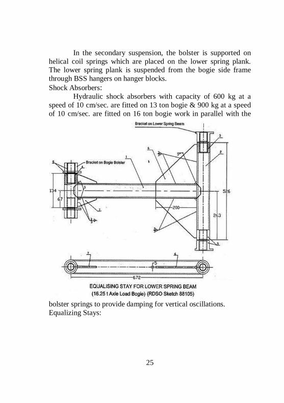
25
In the secondary suspension, the bolster is supported on helical coil springs which are placed on the lower spring plank. The lower spring plank is suspended from the bogie side frame through BSS hangers on hanger blocks. Shock Absorbers: Hydraulic shock absorbers with capacity of 600 kg at a speed of 10 cm/sec. are fitted on 13 ton bogie & 900 kg at a speed of 10 cm/sec. are fitted on 16 ton bogie work in parallel with the
bolster springs to provide damping for vertical oscillations. Equalizing Stays:

26
This device has been provided on bogies between the lower spring plank and the bolster to prevent lateral thrust on the bolster springs as these springs are not designed to take the lateral forces. These links have pin connections at both ends and, therefore, can move vertically
1.3.7 Direct Mounted Roller Bearing Arrangement
Double Row Self Aligned Spherical Roller Bearing
Bearing make Radial clearance in mm SKF 0.105 to 0.296 mm FAG/NORMA 0.080 to 0.185 mm NEI/NBC 0.080 to 0.190 mm
1.3.7.1 ROLLER BEARING DEFECTS
Flaked, pitted, Burnt, Dented, Excessively worn and seized roller- Smearing, Cage broken, Corrosion, Locking stud loose or broken Over greasing, Less grease & Contaminated grease, Felt ring damaged/perished, Retainer ring broken, Excessive lateral play
1.3.7.2 INSPECTION OF OTHER COMPONENTS RELATED TO ROLLER BEARING
The following components other than roller bearing should be inspected during roller bearing maintenance in the workshop. Axle end holes, End locking plates, End locking bolts, Retaining Ring, Collar, Felt ring, Rear and Front Cover, Axle box housing

27

28
1.4 Draw & Buffing Gear:
1.4.1 Draw Gear:
It is a vital component of rolling stock, which is utilized to connect one rolling stock to the adjacent rolling stock to form a train & also to transmit draft forces from engine to last vehicle. It is provided in the centre of the body in the under frame head stock at both the ends. Mainly two types of draft gear are being utilized in Indian Railways. Conventional Draft Gear and Centre Buffer Coupler

29
1.4.1.1 MAIN COMPONENTS OF CONVENTIONAL DRAW GEAR ARE AS UNDER:-
Draft Hook. Draft Links Draft Key Draft Spring/ Draft Pad. Cotter
Washer Bent Pin( U-Pin) Hexagonal Nut. Screw Coupling

30
1.4.1.2 PARTS OF SCREW COUPLING.
1. Link 3. Screw 5. Lever 8. Snap head rivet dia 8 x 85 10. Pin 60 x 218 12. Snap head rivet 12 x 95 14. Snap head rivet 6 x 70
2. Bent coupling link 4. Bent coupling 6 & 7. Trunnion 9. Pin 11. Collar 13. Collar

31
In 1984 use of Enhanced Screw Coupling was started, which was again modified in 1998. To identify this coupling a Dumble mark is stencilled at both the side of coach end body. Length of coupling when fully opened – 997 mm Length of coupling when fully Tight – 751 mm
1.4.1.3 MODIFICATIONS:
Sl. No.
Description Non Modified Modified
1 Working Capacity 36 Tonnes 36 Tonnes 2 Proof Load Capacity 60 Tonnes 70 Tonnes * 3 Breakage Capacity Draw Bar – 108 T
S/Coupling – 112 T 130 T for both
4 Stamping Mark C – 60.61 IS – 5517 Note: *Proof Load Capacity of Enhanced Screw Coupling is increased from 70 T to 75 T. This must be used in all coaches including 24 coach trains.
1.4.2 BUFFING GEAR:
Two nos. of buffers are provided on body head stock on both ends to absorb the longitudinal impacts during run, these are fitted at a distance of 1956 mm. The buffers also transmit buffing forces during pushing to its trailing end stock.
1.4.2.1 THE MAIN COMPONENTS OF BUFFING GEAR ARE AS UNDER:-
1. Buffer Plunger 2. Buffer Socket with securing bolt 3. Buffer Spindle & Plug 4. Buffing Pad
5. Destruction Tube 6. Recoil rubber Washer 7. Washer 8. Nut & Cotter
Mainly Buffers are of two types:-

32
Long Case Buffer – Length from head stock – 635 mm Short Case Buffer – Length from head stock – 458 mm (4 wheeler)
1. Side buffer Casing (casting); 2. Side buffer casing (Forging); 3. Buffer Plunger (Casting); 4. Buffer Plunger (Forging); 5. Face plate for buffer plunger; 6. Flat CSK HD Rivet (Forged); 7. Buffer spindle, 8. Bulb cotter; 9.Rubber buffer spring; 10.Side buffer recoil spring; 11. Side buffer recoil spring parting plate; 12.Recoil spring washer; 13. Buffing spring parting plate; 14. washer; 15. Destruction tube; 16. End plate M 12 X 170 dia; 17. Hexagonal nut M 39 x 3; 18. Hexagonal bolt M 24 x 90; 19. Nylock nut M 24; 20.Spring washer Other data:- Max. Height in Empty condition – 1105 mm Min. Height in Loaded condition – 1030 mm

33
Minimum buffer height of coaching stock should not be less than 1090 mm at the time of releasing of coach from POH Workshop. Allowed variation in height at same end – 64 mm Allowed variation with adjacent vehicle – 75 mm Max. Plunger Travel – 127 mm Min. Plunger Travel – 51 mm No. Of Buffing Pads per Buffer – 14 to 16 Nos. Capacity of Buffing Pads – 1030 kgm
1.5 Brake Rigging
Brake rigging is provided for transferring the braking force from the brake cylinder to the wheel tread. Brake rigging is different for Bogie mounted brake system and under frame mounted brake system.
1.5.1.1 COACH UNDER FRAME MOUNTED BRAKE RIGGING;
In 16.25 t axle load bogie the four levers used in bogie brake rigging are each with lever ratio of 1:1.376 hence the total Mechanical advantage in a bogie is 5.504. In 13 t axle load bogie the four levers used in bogie brake rigging are each with lever ratio of 1:1 hence the total Mechanical advantage in a bogie is 4

34
1.5.1.2 BOGIE MOUNTED BRAKE RIGGING:
The following parts are used in the Brake Rigging. Lever - Straight. Lever - Z shaped Lever Hanger Connecting Link. Bogie brake rigging has been modified to incorporate a total mechanical advantage of 7.644 per bogie for Non-AC coaches and 8.40 per bogie for AC coaches Brake rigging of BMBS is discussed in detail in the BMBS chapter

35
1.6 Maintenance
1.6.1 CLASSIFICATION OF COACHING MAINTENANCE DEPOTS.
According to number of based coaches (holding Capacity), depot is classified into three categories. Sr. No Depot Number of based coaches 1 Minor 50 to 100 2 Medium 100 to 250 3 Major Above 250
1.6.1.1 STANDARD FACILITIES:-
Pitline for examination and repairs of coaches Sick line with covered accommodation Office & store facilities Machinery & plants
1.6.1.2 COVERED ACCOMMODATION:
Length of track under covered accommodation for any type of sick line must be at least 4% of the holdings of the depot (based coaches). The working space required for each coach is 35 m Track length should not be less then 140m for any type of sick line. It is essential to provide 50% track length under a covered area with pit examination facilities with proper light arrangement inside the pit. The pit also be ensured that it is provided with drainage facilities with 1% inclination & required number of man holes. Electric hoist of capacity 3 to 5 tones should be made available to cover the sick line across the track. The width of the covered accommodation should be normally 15 meters covering two tracks under it. The distance between two centreline of tracks should not be less than 7.5 meters.

36
It should be ensured that proper space is provided beside the track for free and easy movement of transport vehicles as like fork lift, lister, trolleys, truck, etc. Entire covered accommodation must have adequate lighting arrangement for workers to work without eye strain.
1.6.1.3 MACHINERY AND PLANT:
To avoid heavy manual labour, wastage of manpower and to provide efficient working environment in depot, suitable adequate machinery and plant is required as under: Synchronised whiting jacks, Coach shunter, Welding plant 200 amp capacity, Gas cutting & welding equipment, Vacuum exhauster, Air compressor (350cfm), 2 tones tram beam hoist, Sewing machine, Light Commercial Vehicle, Wood cutting saw machine, Fork lifts, Hand shearing machine, Portable furnace, Centre lathe, Wheel lathe, Manipulator/fixture for bogie, Ultrasonic testing apparatus, Tool post grinder.
1.6.1.4 TOOLS:
Pneumatic hand tools (a) Grinder (b) Drill (C) Chipper/buster (d) Riveter Electric power tools. (a) Pop riveting tool gun (b) Drill (c) Bolt tighter/torque wrench. Hand tools including torque wrenches as required.
1.6.1.5 TEST BENCHES AND MISCELLANEOUS ITEMS.
Single Car test rig, D.V. Testing bench, Air Brake cylinder overhauling testing bench, Water tank test rig
1.6.2 Primary Depot and Secondary Depot
Sl. No
Primary Depot Secondary Depot

37
1. Complete maintenance of based coaches is attended including the schedules at primary depot.
All maintenance activities on the coaches are to be carried out during pit examination except the schedules at the secondary depot.
2. Preparation of DRS card is done by primary depot.
Only cross checking of items as per DRS card. Shortage/missing if found shall be provided by secondary depot.
3. Primary maintenance depot is responsible to prepare history card of coach.
Intimation to primary depot with regard to any major repair/maintenance is attended.
4. It is duty of primary depot to ensure proper supply of brake van equipment for all originating trains.
Secondary maintenance depot is responsible to ensure only if there is any shortfall.
5. Primary maintenance depot is responsible for all types of schedules of coaches.
Secondary maintenance does not have responsibility other than trip schedule.
6. It is the responsibility of primary maintenance depot to send the coaches for POH or NPOH as per the arising/requirement
Even though it is not the responsibility of secondary depot, it assist in sending the coaches for POH or NPOH through primary depot.
1.6.3 Maintenance Schedules to be Followed in Coaching Depots
Schedule is a work which is to be carried out at a prescribed interval of time.

38
Schedule attention is required to keep the rolling stock in good serviceable condition without any failures during its life cycle for effective utilisation. The different schedules that are carried on the primarily maintained coaching stock are: a) Trip Schedule : After every trip b) ‘A’ Schedule : 1 month ± 3 days c) ‘B’ Schedule : 3 months ± 7 days
d) Intermediate overhaul (IOH)
: 9 months + 30 days
e) Periodical overhaul (POH)
: Once in 18 months (After 24 months for newly built)
f) Special Schedule : As prescribed by each railway
Primary maintenance schedules are required to be carried out by the base depots to which coaches are allotted. In emergency, due to any reason if the coaches cannot reach their base depots and schedules become due, A & B schedules should be undertaken by the Coaching depot where the coaches are available.
1.6.3.1 TRIP SCHEDULE:-
Trip schedule attention is given after completion of every trip. It has to be attended both by primary and secondary depots. The coach need not be detached from the rake during trip schedule attention. Following items are given attention during the trip schedule:- All under gear parts are thoroughly examined, All moving parts are lubricated, Complete examination of buffing & draw gear for its proper functioning. Ensure easy operation of coupling, Properly examine the primary and secondary suspension arrangement. Ensure there is no leakage in dash pot and maintain prescribed oil

39
level. Ensure intactness of safety strap and safety loop. Examine the condition of springs and shock absorber. Properly examine suspension link bracket, BSS hangers, pin & hanger blocks. Examine the equalizing stay for its proper securing. Examine the proper securing of bolts & cotters & silent bushes of centre pivot. Ensure the required level of oil in side bearer. Changing of worn out brake blocks & pins and adjust the brake rigging to ensure prescribed piston stroke. Conduct Rake test as per the procedure, and ensure 100 % brake power. Alarm chain apparatus to be tested. Wheel profile and thickness should be visually examined and gauged in case they appear to be near condemning limits. Thorough cleaning of coach from inside & outside. Disinfection of toilets after cleaning. Examination of all pipe joints & other fittings for leakages & ensure filling of water tank after attention of leakages. Examine for proper opening & closing of vestibule doors and proper fitment of fall plates. Ensure intactness of all amenity & safety items. Preparation of DRS card & brake power certificate.
1.6.3.2 SCHEDULE – A:
Schedule `A' attention is required to be given every month with a tolerance of 3 days at the nominated primary maintenance depot within the normal primary maintenance time on a washing/pit line. A coach need not to be detached from the rake for Schedule `A' examination unless it requires such repairs which cannot be attended to on the washing line or within the prescribed maintenance time on the washing line. Following items are given attention during ‘A’ schedule: All items of trip schedule. Thorough inspection of brake pipe, feed pipe and branch pipes connecting brake cylinder, distributor valve, Auxiliary reservoir and also hose coupling for leakage and give required attention. Carry out manual brake release test on every coach to ensure proper functioning of release lever of distributor valve.

40
Micro switch of ACP should be tested by electrical staff for proper functioning. Clean Dirt collector filter with kerosene and refit. Test the working of slack adjuster in under frame mounted air brake system. Repair/Replace the defective slack adjuster. Examine loops/ brackets and their securing devices and rectify. Examine for wear of brake hanger pins, brake blocks and brake heads and replace if required. Thorough check and repairs of SLR doors for easy and smooth operation and correct alignment of all wearing parts, loose screws etc. Intensive cleaning of coaches. Intensive cleaning of lavatory pans and commode with specified cleaning agent. Thorough flushing of tanks. Checking of water pipes, flush pipe, flushing cocks, push cocks, etc., for ease of operation and free flow of water. Thorough dis-infection of all compartments. Thorough inspection and repairs of draw gear. Thorough inspection and repairs of buffers. Oil in hydraulic dash pots should be checked to detect oil leakage from them through defective seals or through vent screws. Add/replenish with specified grade of oil if oil level is below 40 mm in tare condition to ensure better riding comfort. Similarly oil in side bearer baths should be checked, if the oil is below the plug, replenish with specified grade of oil so that wear plate is fully covered by oil. Inspection and repairs of commode chute. Thoroughly check sliding doors and vestibule doors for easy and smooth operation and correct alignment, lubricate all moving parts. Thorough cleaning of chimneys of dining cars, buffet cars, tourist cars and inspection carriages by wire brushes.

41
1.6.3.3 SCHEDULE – B:
Schedule `B' is required to be given every three months with tolerance of 7 days at the nominated primary maintenance depot within the normal time allowed for primary maintenance on a washing line in rake. Coach need not be detached from the rake for purpose of this examination unless it requires such repairs which cannot be attended to on the washing line or within the prescribed maintenance time on the washing line. The following items of work should be attended. All items of A schedule Painting of lavatories from inside. Thorough inspection and repairs of brake gear components. Examination overhauling and testing of alarm chain apparatus. Thorough checking of trough floor, turn under, etc., from underneath for corrosion. Touching up of painted portion, if faded or soiled. Testing of guard van valve.
1.6.3.4 NEW POLICY (RECOMMENDATIONS) FOR ENHANCEMENTS OF POH/IOH SCHEDULES OF COACHING STOCK.
The revised POH periodicity from 12 to18 months is applicable to all Mail/Express coaches also. A marking on the coach below return date shall be specified to distinguish 18 months periodicity. The general sequence of Schedule will remain as per existing coaching maintenance manual. The items of trip schedules; ‘A’ and ‘B’ schedules will remain same. The coach will be given 2 quarterly schedules (B Schedule) before IOH. The work specified for IOH schedule to mechanical & electrical work in appendix C & D respectively as specified by CAMTECH

42
Pamphlet No CAMTECH 2008 coach POH/1.0 in jan-2008 shall be followed. Technical circulars/pamphlets issued by RDSO with regard to schedules on time to time shall be followed for necessary modification and replacements. The requirement of bogies for unit exchange shall be planned as per the arising of IOH keeping two bogies spare considering the transportation time from the workshop. The periodicity of overhauling of DV is changed from 24 months to 18 months (during every POH) Work shop to switch over to PU painting during POH in workshop as advised by RDSO.
1.6.3.5 INTERMEDIATE OVERHAULING (IOH):
IOH is required to be given every nine months +30 days at the nominated primary depot. Coaches have to be detached from the rake and taken to Sick line for IOH attention. Coach that is detached for IOH is taken over to the washing line for cleaning, lubrication and minor maintenance. The following items of work should be attended for newly built/passenger coaches at the depot during IOH; All items of Schedule `B' Thorough repairs of running gear duly running out of bogies. After lifting and running out of bogies, the bogies/under frame members and body including trough floors of integral type coaches should be thoroughly examined and all parts of running gears are repaired/ replaced as necessary. The bogie frames should be particularly checked to detect damage, cracks or deformation and necessary repairs carried out. Where it is not possible for the maintenance depot to give attention to such heavy repairs or are prohibited to be done in the maintenance

43
depots, the bogies should be sent to the shops for carrying out these repairs. The detailed table of maintenance activities to be carried out during IOH schedule is enclosed as appendix-G. Touching up damaged paint on coaches both outside as well as inside. Thorough cleaning and removal of dust, rust, dirt, etc., accumulated at the pillars through the turn under holes, with coir brush and compressed air. Thorough examination and repairs of upholstery, cushions, curtains, etc. Thorough examination and attention of all Doors and window shutters, for safety catches, safety latches, staples and hasps for ease of operation. Thorough checking and repairs of UIC vestibules, their rubber flanges metal frames, doors, fall plate, locking gear, etc., for ease of operation and safety. Thorough checking and attention to all cracks and worn out portions of flooring in the compartments. Engineer (C&W) of Primary Coaching Maintenance Depots should be fully familiar with the vulnerable areas of ICF coaches for corrosion, viz., sole bar at doorways, lavatories and its adjoining areas, corridor portion etc., special concentration shall be given to SLRs which are more prone for corrosion as it is used in transportation of Fish, Salt, etc. For facilitating inspection of sole bars even spaced elongated holes of (215x127 mm) are already provided in the turn under. Special attention should be given for the following:- Pocket between sole bars and turn under should be thoroughly cleaned through the inspection opening of the sole bars and inspected with the help of torch light or inspection lamps. Drain holes provided in the trough floors should be kept clean and unclogged. During the cleaning of these drain holes any accumulation of water is noticed, the affected area should be very carefully inspected for possible corrosion.

44
Air brake system maintenance; Check brake cylinder for loose rocker arm plate on Bogie mounted Brake Cylinder and change if found defective. Brake cylinder should be checked for smooth functioning and prescribed stroke. Defective brake cylinders shall be sent for repairs. Guard’s van valve should be tested for operation. Test BP & FP air pressure gauges with master gauge and replace if found defective (all the gauges to be calibrated once in 6 months). A set of two master gauges should be kept for this purpose at every Primary Maintenance Depot and each master gauge should be sent one after the other to the workshops for testing, repairs and calibration. Thoroughly clean filter of Dirt collector in kerosene or replace on condition basis. Check working of PEASD & PEAV by hearing the hissing sound of exhaust air. After resetting with the help of key the exhaust of air should stop. Replace the defective PEASD/PEAV. Conduct Single car test of the coach with Single car test rig and record the parameters in the prescribed proforma The date of intermediate lifting should then be stencilled at the appropriate place in schedule chart on the end panel Note: Intermediate Overhauling of Shatabdi / Rajdhanni Exp. Coaches are to be attended in nominated workshop only. Intermediate overhauling of newly built coaches are to be attended after 12 months in the depot duly replacing the wheels with repaired/UT tested wheels from work shop
45
1.6.3.6 LIFTING OF THE BODY FROM THE BOGIE:-
The coach body shall be lifted by using; a) 4 no. of Mechanical Jacks (capacity of 10 T each) OR b) 4 no. of Hydraulic jacks (capacity of 10 Ton each) OR c) 2 no. of Electrical Operated Travelling Crane (capacity of 20 T/25 T each) OR d) 4 no. of Whiting jacks (capacity of 20/25 T each)
1.6.3.7 OTHER TOOLS REQUIRED:-
Trestles. Complete set of Spanners. Complete set of Gas cutting & welding equipment. Different types of hammers. Wooden Wedges & Packing. Tool kit
1.6.3.8 ITEMS TO BE DISCONNECTED BEFORE LIFTING OF THE BODY:
Remove of centre pivot cotter [If lifting is being done by E.O.T cranes or whiting jacks] Unscrew and remove centre pivot studs [If lifting is being done be mechanical/hydraulic jacks] Unscrew air vent screw of dash pot. Disconnect Dynamo belt. Disconnect S.A.B pull rod. Disconnect lateral shock absorber if connected Disconnect axle box safety loops. Remove commode chute if it is infringing. Remove foot board if required. Remove dummy carrier if infringing. Insert required thickness of wooden packing between upper portion of bolster & Bogie frame.

46
Following are the causes of low buffer height in ICF coaches; Wear of wheel. Loss in stiffness of coil springs provided in primary and secondary suspension. Wear in Bronze wearing piece and wear plate of side bearer. Wear on link brackets, stone & pin provided on secondary suspension arrangement. Procedure for buffer height adjustment in ICF coaches. To achieve required buffer height standard size of wooden packing pieces are used which are provided below the coil springs of primary suspension as given under. New Wheel dia :- 915 mm Condemning: - Solid Wheel: 825 mm.
Note:- 6 mm compensating metallic ring can also be used if required. Further requirement can be managed by utilising wooden packing which comes in two halfs of size 8 mm & 12 mm thickness but, it should be ensured that total thickness of wooden half packing + compensating ring should not be more than 20 mm. After buffer height adjustment the safety loop of axle box also to be adjusted to ensure a gap of 40 mm between the Axle box lug & safety loop. Running clearances i.e. ‘A’ & ‘B’ also should be ensured.
Sr No. Wheel Diameter (mm) Thickness of Wooden Packing (mm)
1. Below 889 up to 863 13 2. Below 863 up to 839 26 3. Below 839 up to 825 38

1.6.4 RPC-4 Revision-Jan 2007 (No. 95/M/C/141/1)
Sub:- Revised maintenance pattern of coaching train- running up to 3500 km in round trip with terminal attention at the other ends. Sl No
Category of train
Preventive maintenance at pit line
Under gear/ Brake System maintenance at pit
Internal cleaning, passenger amenity fittings and watering
External cleaning nominated line with proper facilities
En route/terminating
Brake system check prior to start at plate form/at other end
1 Mail/Exp. One way run > 3500 km
At primary end
At both the ends
At both the ends
At both the ends
En route after every 250-350 km location to be decided by Rly for each train. Terminating examination at terminating station.
Complete air brake testing with fresh BPC
2 Mail Exp one ---do---- ---do---- ---do---- At both ---do---- ---do----

48
way run <3500 km but round trip run >3500 km
the ends
3 a Mail Exp round trip run up to 3500 km
---do---- Only at primary end
---do---- ---do---- ---do---- Only continuity check if stabled at platform for 2 hrs, otherwise brake power check with endorsement on BPC engine
3b Inter connected Mail Exp round trip run up to 3500 km
---do---- To be done after 3500 km or 96 hrs after issue of original
At primary end & each terminal
---do---- ---do---- ---do----

49
BPC whichever is earlier at primary end
4 Passenger trains with toilet including interconnected passenger shuttles
---do---- ---do---- At primary end
---do---- ---do---- ---do----
5 Passenger trains without toilet
---do---- To be done after 3500 km or 7 days, after issue of original BPC whichever is earlier only at primaryend
---do---- ---do---- Once a day at primary end or at nominated terminal
---do----

50
Note: - Internal cleaning, passenger amenity attention and watering may be done at platform line or nominated stabling line provided stipulated facilities are available at such line, in case the rake is stabled in yard for more than 6 hrs, positive safety arrangements should be made for the rake and in case the security is considered inadequate, the rake should be taken to pit line for attention to under gear as given under column (4) above. Difference between IOH, POH & NPOH
Sl. No
IOH POH NPOH
1. Intermediate Overhauling. Periodic Overhauling. Non Periodic Overhauling.
2. Once in 9 months (for new built coaches after 12 months)
Once in 18 months (24 months for newly built coaches)
Time Period is not fixed for any vehicle for NPOH
3. IOH of coach can be carried out in sick line where facility to lift the coach is available.
POH is carried out only in workshops.
NPOH is carried out in workshop.
4. During IOH all the parts of under gear are thoroughly examined and replaced if necessary. For Mail/Exp coaches, Bogie is replaced as unit and the old is sent to workshop for
At the time of POH all parts of under gear are dismantled and should be replaced if there is any wear and tear.
At the time of NPOH all parts of under gear are dismantled and should be replaced if there is any wear and tear.
51
repair and return. 5. At the time of IOH painting of
complete coach is not necessary, only required places are touched up.
Painting of whole coach is necessary.
Generally painting of coach is done completely

1.6.5 FACILITIES REQUIRED FOR MAINTENANCE OF 24 COACH TRAINS
(Railway Bd.'s letter no. 98/M(C)/137/19 Pt. I dt. 28.7.99 & dt. 05.05.2000)
1.6.5.1 INFRA STRUCTURAL REQUIREMENTS
24 coach length fully equipped pit line. High pressure jet cleaning pipeline with plant for cleaning at primary pit line. Mechanized external cleaning is preferable. Water hydrants for 24 coach length at en route watering stations with 20 minutes stoppage at nominated stations. Availability of the prescribed air brake maintenance and testing equipment.
1.6.5.2 COACH DESIGN RELATED REQUIREMENTS
Air brake with twin pipe graduated release system Only enhanced capacity draw gear and screw coupling to RDSO sketch No. 79061 and 79067 are to be provided on the rake
1.6.5.3 MAINTENANCE PRACTICES AND SYSTEM RELATED REQUIREMENTS
The integrity of the rakes to be maintained. Primary maintenance of the rake should be done in one hook without splitting. Minimum maintenance time of 6 hours on the pit during primary maintenance to be ensured. Trains leakage rate to be maintained within prescribed limits by using rake test rig. Provision of proportionate brake system on the locomotive in good working order. Provision of audio visual alarm system on the locomotive. In case of double-headed diesel locos maximum traction motor current will be restricted to 650 Amperes and in case of double headed WAP1/WAP3 electric locos, the traction motor current

53
limit will be 750 Amperes as prescribed in RDSO 's instructions for operation of main line air brake trains - C-9408.
1.6.5.4 OPERATIONAL REQUIREMENTS
Communication between driver and guard should be provided through suitable means. Special care to ensure no gap between coach buffers after tightening the coupler. No additional coach attachment beyond 24 coaches will be permissible. Note: As per Railway Board Instruction now one occupied saloon & one parcel van can be attached with 24 coaches rake.
1.6.6 EXAMINATION OF TRAINS
Ref: IRCA Rule Book Part – IV (Ch. 3)
1.6.6.1 ROLLING IN EXAMINATION:
There are certain types of defects in rolling stock which can only be detected during the motion of train. To detect such type of defects, rolling in examination is adopted. This examination is carried out on all pass through trains and terminating trains. To carry out Rolling in examination, C & W staff and supervisor will take position on both sides of platform / line in which train is being received. During examination following defects are detected; Unusual sound due to flat faces on tyre of wheel in any vehicle of train. Whistling sound from bearing, if unattended that can lead to hot box. Hanging part or loose fitting on the vehicle. Any Spring broken. Brake binding on any vehicle. Any component of spring suspension like bracket loose/broken etc.

54
Any abnormal behaviour of vehicle during run. Any other defects which can affect the safety of the train.
1.6.6.2 ROLLING OUT EXAMINATION:
The procedure of conducting Rolling out examination is similar to rolling in examination. Supervisor and staff will take position for conducting examination ahead of engine and ensure that the brakes of all vehicles are in released condition and any other defect that can be noticed like in Rolling in examination and could have leftover during the previous examination and can hamper the safety of the train. Sr.DME/ DME in charge shall nominate the location for carrying out Rolling in/Rolling out examination after personal inspection of site. While nominating the site following should be kept in view: Site shall provide unobstructed view of under gear from both sides. Speed of the train shall not be more than 30 Kmph, the track should not have any rail joints at the location, It should cover the entire length of train, Should have adequate space for arrangement of shelter for staff. It should be ensured that proper lighting arrangement is provided on both the sides of the track at nominated spots for examination of under gear parts during night. Focusing of lights shall be done by keeping a coach on the line and adjusting the angle of light to illuminate under gear and bogie.
1.6.6.3 EXAMINATION OF ORIGINATING TRAINS
All trains must be examined by the mechanical train examining staff before dispatch to ensure that all coaches in the train are fit to run, without rejectable defects (for reject able defects, please refer to IRCA Conference Rules, Part IV). Station Master (SM) shall handover part B & C of check memo (T431) to Senior Section Engineer (C&W) after placement of the formation in pitline for

55
Examination, cleaning and watering. After carrying out all necessary examination and work, SSE (C&W) shall communicate fitness of the train to Station Master by giving part C of T431 duly getting acknowledgement in part B. The Station Master shall not dispatch the train unless the fitness certificate is received from SSE (C&W). The level of the air pressure/vacuum on the train engine and the brake van gauges as well as the percentage of operative cylinders should be recorded on Brake Power Certificate and signed by Junior Engineer/C&W, Driver and the Guard of the train. Trains which have been attended on pit line should have 100% brake power and no train shall be allowed with an inoperative/defective Brake cylinder on any coach after pit attention. Trains which are attended on platform or where secondary examination has been dispensed with or en-route should have minimum 90% brake power.
1.6.6.4 EN ROUTE/TERMINATING EXAMINATION OF PASSENGER TRAINS
Rolling in examination of the train has to be conducted for the terminating trains. After train comes to halt, it should be ensured that the train is protected from both the sides (with the stop board/red flag during day time and red lamp during night time) before commencing the examination of the train. It should be ensured that a suitable indication board is placed at conspicuous location visible to the driver indicating that C&W staff is at work. Temperature of the axle boxes should be checked & recorded preferably with the help of the Non contact infrared thermometer. Brakes of the coaches to be released manually and ensure complete release by physically moving the brake beam. Other under gear parts should be examined visually to ensure that the train is safe to run further. Repairs if required should be carried out on pass through trains by taking shortest required time to avoid detention to train to the extent possible.

56
Lavatories of the coaches should be properly cleaned using High pressure water jet machine provided at nominated stations during halt of the train. Any complaint from passengers should be attended promptly to the satisfaction of the passenger After attending to any required repairs only stop board/red flag should be removed. C&W control should be informed about any out of course work done. C&W control shall repeat the out of course work done to the Primary Maintenance (PM) depot after corrective action. At the train examination stations where locomotives are changed on through trains, the level of air pressure/vacuum created on the locomotive and brake van gauges should be recorded on the BPC. The inoperative/blanked cylinders, if any, should also be written in the certificate for their information. This certification should be an endorsement on the original brake power certificate; no fresh brake power certificate needs to be issued.
1.6.6.5 PIT EXAMINATION OF PASSENGER TRAINS
1.6.6.6 RELATED TO SAFETY;
Protect the Examination line. Thorough examination and repair of Underframe, Bogie, Brake gear, Draw & buffing gear. Test and repair of Vacuum / Air brake system for Brake power including test/repair of Passenger alarm system. Lubricate all moving and rubbing parts. Give preventive maintenance schedule attention for the coaches except IOH.
1.6.6.7 RELATED TO AMENITIES;
Dry sweeping, Cleaning, Swabbing, Watering, Pipe fitting work, Trimming work, Carpentry work, Padlocking, Painting.

57
1.6.6.8 WASHING AND CLEANING OF COACHES
Wherever washable aprons are available on the platforms, the time available before the terminating trains are pulled out from platform and backed to the pit line/yard, should be utilized for inside sweeping and toilet cleaning. External Cleaning / Washing i) Place the rake/coaches on the washing pit provided with equipments required for washing and cleaning. It should be ensured that the rake/coach is protected with proper board/signal for safety of the staff working and to prevent movement/disturbance in the activity. Scotch blocks with locking arrangement should be used to protect lines and keys should be kept with SSE(C&W) till the time rake is under maintenance. ii) Before starting washing and cleaning of side wall, ensure that the glass shutters and louver shutters of that side are lowered. Remove dirt/dust accumulated on shutters by compressed air or duster. iii) Remove old reservation charts/labels on the body panels. Splash water on old charts so that they are wet and can be easily removed. Care should be taken to avoid any damage to the paint. iv) The cleaning solution should be spread/rubbed with nylon brush or sponge brushes and then rubbed thoroughly to clean the panels. Extra attention should be given to oily and badly stained surfaces. Use recommended solutions for cleaning as per RDSO specification No. M&C/PCN/101/2001 or use cleaning agents approved by CME of the Railway. v) Destination boards may be removed and cleaned with brush/duster. vi) Clean the external surface by high pressure jet where facilities are available. vii) All exterior panels including end panels should be hosed with water and brushed with diluted soft soap (detergent solution)

58
The strength of the solution may be increased or decreased according to RDSO specification M&C/PCN/101/ 2001. Cleaning of Toilet i) Before starting cleaning of toilets ensure that all repairs in the toilets have been carried out and after cleaning no employee should enter in the toilet. ii) Doors and walls should be cleaned with water sprayed by high pressure jet up to waist level. Apply specified solution and rub thoroughly with sponge brush/ nylon bristle brush. iii) Indian style lavatory pans have to be cleaned by thorough rubbing with concentrated solution of recommended cleaning agent. iv) Western style commode shall be cleaned as (iii) however due care should be taken that the cleaning solution does not fall on commode lid which may damage/spoil it. v) The flooring should be rubbed with nylon bristles/sponge brush and cleaned with recommended cleaning agent. The drain holes should be cleaned thoroughly for easy discharge of water. vi) The mirrors in toilet should be cleaned with light wet cloth. Recommended solution should be used for cleaning the dirty portion of glasses. vii) After all the washing and cleaning in the toilets mentioned above, the toilets should be thoroughly cleaned with water jet and water should be flushed out. All fittings and floor should be wiped dry with a cloth. viii) After cleaning, spray deodorant in the toilet to remove the bad odour. Internal cleaning of upper class AC and sleeper coaches Empty the magazine bag and waste from dust bin. Sweep the whole coach with broom in sleeper coaches. Clean the floor of AC coaches with vacuum cleaner. Remove dust from floor, berths/seat, and magazine nylon wire mesh bag fitted on panels and fan guards with duster. Use of vacuum cleaner is recommended in such areas.

59
Also remove dust/dirt from under the berths, window sill, and sliding door, railing corner and all corner & crevices of coach interior with vacuum cleaner if provided. Ceiling panels, wall panels, cushion berths, fittings, table top, etc. should be cleaned with duster and stain marks on these should be removed by use of recommended soft detergent. Aluminium frames, strips, and other metal fittings, etc. should be cleaned with recommended cleaning agent. FRP window frames, louvers, etc. should be cleaned with recommended solution and rubbed out by nylon brush or sponge /duster to remove stain marks. Alarm chain handle and its holding bracket should be washed and cleaned. The PVC flooring should be rubbed with nylon bristles/sponge brush and cleaned with recommended cleaning agent. In AC coaches, the amenity fittings and toilet fittings such as coat hanger, stools, arm rest, foot rest, towel hanger, etc. should be cleaned with duster. Stains on these items should be removed with recommended detergent solution. The compartment carpet should be cleaned with vacuum cleaner. Every month, the carpet should be cleaned thoroughly by taking it out from compartment and if necessary they should be dry cleaned in every three to four months. Before re-laying the carpet, the compartment floor should be thoroughly cleaned. Spray recommended air freshener in the coach. No employee should be allowed to enter the coach for any purpose/work after complete cleaning Curtains in the AC Coaches and Tourist Cars should be removed for periodical washing and cleaning. Faded and damaged curtains should be replaced on condition basis. Precaution should be taken to prevent nuisance of cockroaches in AC coaches and pantry cars by periodical disinfestation. No repair works on Electrical train light/fan/AC) or Mechanical account should be left to be carried out after washing and cleaning of the coach.

60
Internal Cleaning of GS, SLR i) Cleaning of GS, guard and passenger compartments of SLR should be done as mentioned above in sleeper coaches. ii) Interior surfaces of parcel and luggage vans should be cleaned thoroughly with recommended detergent and water, and the water should be completely flushed out and make the compartment dry with out any moisture. Cleaning of buffers and screw couplings i) Buffer plungers should be scrubbed with a scraper to remove dirt and muck. Thereafter, they should be wiped clean and lubricated with oil. ii) Screw coupling threads should be cleaned with wire brush to remove all dirt and dust. Thereafter, it should be cleaned and given a light coat of oil.
1.6.6.9 BOGIES
Depot maintenance staff should ensure the following things in respect of proper functioning and safety of Bogie & Bogie components.
1.6.6.10 BOGIE FRAME
During every trip, and Schedule A & B the following examination should be conducted Examine visually condition of bogie side frame, transom, longitudinals etc especially at all welded locations. Examine rubber stopper and crown bolt of axle box for damage/missing/loose. Examine axle box safety straps/loops for damage/broken/missing. Examine Bolster safety straps/loops for damage/broken/missing. Examine Brake hanger brackets for damages. Examine the brackets for safety wire rope of brake beam. Examine visually BSS hanger brackets. Examine visually anchor link brackets.

61
Visually examine centre pivot mounting bolts and attend if needed. Visually inspect centre pivot cover. Side bearer oil to be replenished in A & B schedules, if needed. During IOH at depot Attend all items as above. Examine condition of wearing piece and wearing plate. Examine oil level in side bearer oil baths and replenish if oil level has gone down below the level of last thread of oil filling cup.
1.6.6.11 PRIMARY SUSPENSION
Every trip Visually examine axle box springs for breakage. Visually examine dash pot oil filling special screw for deficiency. Check oil leakage in dash pot through defective seals/vent screws. Visually examine axle box clearance Schedule A & B Examine all items as above. Add specified grade of oil in dash pot. Visually examine and adjust axle box clearance. During IOH at depot Examine as per (ii) above. Examine the axle guide assembly by lifting the coach and give any attention if necessary. Check axle box clearance with gauge and adjust.
1.6.6.12 SECONDARY SUSPENSION
During every trip, and Schedule A & B the following examination should be conducted Visually examine bolster springs for breakages or any other defects. Visually examine Bolster lower spring beam. Visually examine BSS hangers, hanger blocks, BSS pins.

62
Check bolster clearance between top of bolster and bottom of bogie frame. Visually examine equalising stay rods and pins (small and big). Visually examine Equalising stay rod brackets. Check and attend safety loops of Equalising stay rod. Visually check anchor links, and its securing bolts and attend if needed. Examine and attend safety loops of bolster. Examine vertical shock absorbers for damages. During IOH at depot Dismantle Secondary suspension and measure the dimensions of Spring, BSS hangers, Hanger pins, Hanger blocks and the hole in the bracket. Remove the equalising stay, measure the pins/bushes for any wear and regrease the pins After assembling maintain the Bogie ‘B’ dimension as prescribed
1.6.6.13 BRAKE RIGGING
Every trip Check brake gear and adjust so that the piston stroke is within the limit. Examine brake beams for breakages/damages. Check and attend brake beam safety wire ropes/safety straps. Check and attend brake shoe head and key & replace if necessary. Check and replace worn brake blocks. Visually inspect and replace brake hangers, brake gear pins and cotters/split pins if necessary. Visually inspect and replace damaged/missing brake gear bushes. Schedule A & B Examine as per above. Check and attend brake block adjuster. Examine and attend brake levers

63
Examine and attend floating lever suspension brackets During IOH at depot Examine all items as above Examine and replace all brake gear components found deficient and worn out
1.6.6.14 DRAW GEAR
Every trip, Schedule A & B Check and replace damage/missing split pins/cotters/rivets. Examine draw hook, draw bars and rubber pads for damages. Check condition of the screw coupling and its components and replace if required. Check condition of draw beam and locating pins on it. Examine visually draft key locking pins. During IOH at depot Examine all items as above Ensure that wear on screw coupling shackle pins, trunnion pins, shackle/link holes and draw hook holes should not exceed 3 mm. Ensure that wear at any section on draw hook should not exceed 10 mm.
1.6.6.15 BUFFING GEAR
Every trip, Schedule A & B Visually examine Buffer plunger for drooping, crack/wear and stroke length. Examine Buffer casing for crack and its securing arrangement. During IOH at depot Dismantle the buffer assembly, and check for perished pads, distruction tube, worn out Buffer face/spindle etc and attend/replace where ever necessary Buffer alignment with head-stock should be true.

64
Buffer projection should not be less than 600 mm and not more than 635 mm.
1.6.6.16 WHEEL AND AXLE
Every trip, Schedule A & B Examine visually axle box for grease oozing and warm box and any damages/loose covers. Visually examine the profile of the tyre and check with tyre defect gauge if appears nearing condemning limit. During IOH at depot Check the wheel distant gauge for loose/tight wheel Examine axle pulleys on the wheels Limits for flat tyres The limits for permissible maximum flat surfaces on tread for BG ICF coaches is 50 mm (reference Rly. Bd.'s Letter no. 83/M (N)/960/1/Vol I dated 15/18.3.99) In addition to normal checks, wheels to be checked for defects as per CMI – K 003.
1.6.6.17 ROLLER BEARING AXLE BOXES
A coach should invariably be detached from service for the following defects Hot axle box Damaged axle box Damaged front or rear cover Seized roller bearing Coach involved in accident, derailment, fire, flood etc.

65
Care should be taken not to keep a coach fitted with roller bearing stationary for a long time. Coaches stabled for a long time should be shunted up and down at regular intervals. Coaches fitted with roller bearing should be ensured that: - No wash basin drain hole / discharge pipe is directly above the axle box The front and rear covers of the axle boxes are not damaged, cracked or loose Clearance between axle box and wheel is such that the axle box does not rub against the wheel. Brake gear is properly adjusted to avoid possibility of brake binding
1.6.7 SAFETY & AMENITY FITTINGS
The fittings which are fitted in the coach for safety of passengers & their luggage are called as “Safety Fittings“. The fittings which are provided inside the coach for comfort, Luxury and also for non strenuous journey of the passengers are called as “Amenity Fittings“.
1.6.7.1 FOLLOWING ARE SOME OF THE SAFETY FITTINGS PROVIDED IN THE COACHES;
Alarm pull chain Internal latches on top & bottom on body side doors Provision of pad locking arrangement from out side of body side door Internal latch and tower bolt for compartment doors in first class Vestibule doors/shutters with locking arrangement Latches for window shutters Fire extinguishers Safety bars on all window openings Window shutters both glass and louvre Sealed window glass for AC coaches

66
Frosted glass shutters for toilets
1.6.7.2 FOLLOWING ARE SOME OF THE AMENITY FITTINGS PROVIDED IN THE COACHES;
Lights and fans inside the coach, Reading light with switches for upper class coaches, Charging socket out let in upper class coaches & sleeper coaches, Cushioned berths and seats & back rest, Luggage racks, Folding or fixed tables, Roof ventilators, Tumbler holder, Dust bin, Foot steps in sleeper coaches and foot rest for chair cars, Notices, Mirror with shelf, Coat hook, Magazine pouch Bottle holder, Wash basin, Wardrobe with fixed handers for 1st AC Rings below berths for securing luggage, Shower bath, towel rail, flushing commode & pan, coat hook, liquid soap container, push cocks, hand rail, mirror with shelf, soap dish etc in lavatories, Destination boards, Reservation display plates, Coach indication boards.
1.6.8 NMG COACHES
The coaches with age of 20 – 21 years or later are being converted during POH for the purpose to carry Automobile (Express). These coaches are known as NMG coaches and the rakes formed with these coaches are called NMG rakes. Following are the features:- Load carrying capacity is 12 ton maximum. Speed 75 kmph & 100 kmph Max. The life of such converted coach is 30 years from the date of original manufacture. Wider end opening of 2800 mm × 2200 mm. Improved adjustable internal locking and lashing arrangement to avoid damage to the vehicle during transit. The periodicity of POH is 24 months.

67
1.6.8.1 MAINTENANCE PATTERN FOR NMG RAKES
(As per Rly. Bd's Letter No. 91/M (C)/650/1 dated 29.5.2000) In order to optimize utilization of NMG rakes it has been decided to introduce the following maintenance pattern: NMG rakes may be run on goods pattern with intensive examination at both the ends, following other conditions for en-route detention in case at stabling at road side stations. In case of close circuit runs up to3500 km, the rake may be run on round trip basis. Close circuit rake must be clearly identified and should have a nominated base depot where adequate trained staff and spares should be available. Each NMG coach should be marked with the nominated POH workshop and return date. The maintenance schedules of the NMG coaches will continue to be on the coaching pattern to be carried out by the base depot. Using these coaches as parcel vans for running on piecemeal basis on passenger carrying trains is strictly prohibited. Each coach should be stencilled at a suitable place on its end panel, the code of the base depot and a schedule chart. The date and station code of the depot where a particular schedule is carried out should be stencilled at the appropriate place in the schedule chart immediately when the schedule is completed.

68
1.6.9 IOH/POH periodicity of ICF coaches;
(Rly Bd letter No.2007/M(C)/141/1 Dated: 26.09.2008 & 06.08.2009) D.O.No.2007/M/(C)/141/1 dated: 12.02.2009 by MM to all CMEs
Periodicity (months) Coach category IOH (in
depot) IOH ( in workshop) POH
New coach turned out by PU or a coach turned out after MLR 12# - 24
Rajadhani/Shatabdi - 9 18 Mail/Express, Garibhrath, Janshatabdi and OCVs forming part of standard rake composition of Mail/Express trains
9^ - 18
Passenger 9@ - 18 Other OCVs 12@ - 24 Note: The concept of C schedule in the depots, hitherto being followed on the Railway, ma be done away with and replaced by an IOH as under. # The bogies must be rolled out and IOH schedule carried out on the bogies in the coaching depot itself with mandatory replacement of overhauled wheel sets supplied by the workshops. The attended bogies must then be provided in the same coach. The IOH schedule is applicable to all new ICF design coaches irrespective of the train category being serviced by them. ^ Unit exchange of overhauled bogies supplied by the workshops must be ensured. @ The Bogies must be rolled out and the IOH schedule carried out on the bogies in the depot itself retaining the wheel sets, unless

69
specific attention or change is warranted on the wheel sets. The attended bogies must then be provided in the same coach.
1.6.10 MAXIMUM ALLOWABLE INEFFECTIVE PERCENTAGE
Authority: Railway Board Letter No: 86-M/(N)/951/7 of 26.6.87 Sl. No
Description Non- AC (Ineffective %)
AC (Ineffective %)
1 In Workshop for POH 6.0 9.0 2 In workshop for
nominated repairs 0.5 -
3 Stabled in yards awaiting workshop repairs
1.0 -
4 C&W depots for repairs to Mechanical & Electrical equipment
2.5 3.0
Total: 10 12
1.6.10.1 AVERAGE LIFE OF COACHES
Sl. No
Types of Coaches Average life in years
1 Steel bodied coaches 25 2 IRS coaches 30 3 Light utilization categories of
coaches (Except restaurant / pantry car for which life is 25 years)
40
1.6.11 Following are the few items that Workshop shall ensure during POH;
The lowest permissible wheel diameter for a coach turned out after POH shall not be less than 837 mm.

70
If the buffer height requires adjustment, the load on the axle box springs should be released and the packing rings in halves shall be inserted below the axle box springs. The total height of primary springs and compensating rings should not exceed 295 mm. There should be a minimum clearance of 40 mm between the axle box wing lugs and their safety straps. The clearance between the axle box crown and the bogie frame should thereafter be adjusted as per the table given below: Type of coach Crown clearance in mm SCN, VPH, WCB, WFC 45 +0/-3 WFAC, WSCZAC, WCBAC, WLRRM, WFCZAC, WACCW
36 +0/-3
SLR, GS 48 +/- 3 WACCN 34 +/- 3 WGSCZAC, WGFAC, WGACCW, WGFACCW, WGACCN
26 +/- 3
The Bogies shall be trammeled for squareness as per the following; Suggested BSS bracket and axle guide alignment gauges
13t bogies 16.25t bogies
Longitudinal gauge for BSS brackets
1400±1.0 mm (700±0.5 mm from longitudinal center-line)
1500±1.0 mm (750±0.5 mm from longitudinal center-line)
Transverse gauge for BSS brackets
2159 ±1.0 mm 2159 ± 1.0 mm
Diagonal gauge for BSS brackets
2573 ±1.0 mm 2629 ± 1.0 mm
Longitudinal gauge for axle guide
570±1.0 mm (equidistant from center-line of axle)
570 ± 1.0 mm (equidistant from center-line of axle)

71
Transverse gauge for axle guide
2159±1.0 mm 2159±1.0 mm
Diagonal gauge for axle guide
3612±1.0 mm 3612±1.0 mm
Distance between BSS bracket and adjacent axle guide
463±1.0 mm 413±1.0 mm
Longitudinal gauge for suspension strap
870±1.0 mm (equidistant from center-line of axle)
870±1.0mm (equidistant from center-line of the axle)
Tolerances for Bogie components Part name Wear location Brake hanger bracket bush
32 H7 Hole +0.025/-0.00
Brake hanger bracket 35 gap Brake hanger bracket C.D.1752 +1.0 Axle guide 115g6 -0.034/+0.00 diameter Axle guide 120 diameter BSS bracket bush 38 dia. Hole Pin for BSS 37 diameter Bracket for anchor link 25+0.021/-0.0 slot Brake lever hanger bracket
32 dia hole
Anchor link silent block pin
25 mm -0.012/-0.052, thick ends
Anchor link silent block Outer dia. 90.5 +0.05/+0.025 Anchor link housing Hole dia 90.5 +0.015/ -0.03 BSS hanger distance between horizontal wearing
arms 384 BSS hanger thickness of vertical arm 25.5 BSS hanger horizontal wearing surface 42

72
Hanger block Thickness - 9.5 Hanger block slot 29 (+0.4/-0.2) BSS pin thickness across flat
29 (+0/-0.1)
Lower spring seat Inner dia 140 H7 (+0.04/-0.0) Guide bush Outer dia. 140 A9 (-0.3/-0.6) Guide bush Inner dia 115 (+0.15/-0) Guide Ring Inner dia 115 H7 (+0.04/-0) There shall not be any leakage of oil from the side bearer. Hard ground plate in side bearer, should not be worn more than 1.0mm in thickness or ridges formed on the plate. Bronze wearing piece for side bearer, should not have worn more than 1.5 mm in thickness. Sharp edges on wearing piece should be rounded off before re-use. Dust seal cover shall sit effectively all around without any gap on the oil-bath and the sleeves slide freely on the guide to ward off dust and moisture coming in contact with the oil. The oil filling plugs should be well secured by chain to prevent it from dropping. Equalising stay pins should not be worn more than 1 mm in dia (31 mm standard), all the bushes and washers to replaced. Maximum dimensional clearance between the pins and bushes of brake gear should be within 1.5 mm. Springs shall be subjected to load test and grouped as per the following tables. Drawing code of springs for ICF BG coaches Type of spring Type of Bogies ICF Drg No. Code
All Non AC F-0-1-006 A 01 All AC WTAC -0-1-202 A 03 Power car WLRRM 2-0-1-202 A 04 Double decker DD-0-1-001 A 06
Axle Box
High capacity WLRRM 8-0-1-802 A 09

73
power car High capacity parcel van RDSO/SK-98017 A 10
All Non AC F-0-5-002 B 01 All AC WTAC -0-5-202 B 03 Power car WLRRM 2-0-5-202 B 04 Double decker DD 0-5-003 B 06
B11 High capacity power car WLRRM 8-0-5-802 B 13
B15
Bolster
High capacity parcel van RDSO/SK-98018 B 16

Code Wire
dia Free height
Test Load
Acceptable height under test load
Groups as per loaded spring height
A B C Yellow Oxford Blue* Green A01 33.5 360 2000 279-295 279-284 285-289 290-295 A03 33.5 375 2800 264-282 264-269 270-275 276-282 A04 35 372 3000 265-282 265-270 271-276 277-282 A06 36 337 2400 269-284 269-273 274-279 280-284 A09 37 360 3000 277-293 277-282 283-288 289-293 A10 39 315 1800 276-289 276-279 280-284 285-289 B01 42 385 3300 301-317 301-305 306-311 312-317 B03 42 400 4800 291-308 291-296 297-303 304-308 B04 47 400 6100 286-304 286-291 292-297 298-304 B06 36 416 4200 280-299 280-286 287-292 293-299 B11 47 B13 34 *386 6700 306-322 306-311 312-317 318-322
B15 40 393** B16 32.5 286** 6000 256-272 256-261 262-267 268-272
* combined load deflection test is done ** As per RDSO letter No. MC/MV dtd: 21.11.2001

The maximum diametrical clearance between the lower spring seat and guide bush should not exceed 1.6 mm. The bogie should sit evenly on the four axle boxes. The assembled bogie should be tested for normal working load and the bogie frame height should be 686 ± 5 mm. Safety straps of the axle box wing lugs and bogie bolster should be adjusted so as to ensure a minimum clearance of 40 mm between the lugs and bottom of safety straps. After placing the wearing plate and wearing piece in side bearer oil-bath, each side bearer oil-bath should be filled with 2 litres of any of the following approved brands of oils. Servoline – 100 of IOC Yantrol – 100 of HPC Bharat univol – 100 of BPC Apply graphite grease on Centre pivot pin Shock absorbers should be given a schedule overhaul, when their capacities vary beyond ±20% of their specified values, or after 4 lakh kilometers or alternate POH, whichever is earlier. The shock absorber is tested on the special purpose machine which can measure its capacity in both tension and compression by developing the resisting force at a velocity of 10 cm/sec. Variation in diameter of wheel should be within tolerance as given below; On the same axle 0.5 mm On the same bogie 5 mm On the same coach 13 mm Draw hooks and screw coupling (Stc. 60-61) should be tested at 60 t and those of IS:5517 Gr. 35Mn6Mo3 should be tested at 75 t respectively. There should be no permanent set after release of load. The draw bar should not have dimensional distortions and damaged threads. The draft key should not be bent or worn out

76
All the draw bar and hook should have been tested by magna-flux for surface cracks. Draw bar (Stc. 60.61) should have been load tested at 39.5 t and those of (IS 5517 Gr. 35Mn6Mo3) at 60t. There should not be any permanent deformation. The draft pads which are bulged, perished or having set to a length below 186 mm should be changed during POH (New Rubber draft pad pack to STR No.C- 9501 (Rev.2) free height along with parting plates is 208 mm and 196 mm pre compressed length is achieved after tightening the castle nut).The pads should be changed invariably as a set every alternate POH, and all the in a draw bar assembly should be from a single supplier. Draft Yoke should be free from welding cracks distortions. The wear on the following locations shall be within the limits given below;
Location of wear Wear limit
Suggested no go gauge
Draw Hook Root of hook near point of contract with bent link
13 mm Profile gauge with 15 mm adjustable projection
62 mm dia pin hole 3 mm 65 mm flat Bottom side of shank 56 mm height
15 mm 41 mm snap
Draft key slot(159 mm) in hook
13 mm 173 mm flat
38 mm width of key slot in hook
2 mm 40 mm flat
Hook opening 48 mm 5 mm 46 mm go 53 mm no go plug
Draw Bar 155mm draft key slot in draw bar
9 mm 164 mm snap
39 mm shank body 3 mm 36 mm snap Slot width 38 mm 2 mm 40 mm flat
Threads M39x3 1 mm Thread profile Draft Key Draw bar seating 139 mm
4 mm Profile gauge with 5 mm adjustable projection
Draw hook seating 139 mm 4 mm Profile gauge with 5 mm adjustable projection
Thickness 36 mm 4 mm 32 mm snap
Cotter hole 14 mm dia 2 mm 16 mm plug Draft Yoke Assembly Draft yoke hole (45mm) 3 mm Draw gear pin dia (31 mm) 1 mm
Bush (32 mm) 1 mm

77
The projection of the shoulder on the draw hook from the head stock after assembly should be within 92 mm – 120 mm. The buffers should not be cracked or damaged/deformed The location of 4 securing holes of buffer casing are 85 ± 0 .2 mm from centre of casing along width & 174.5 ± 0.2 mm along length in buffer casing to SK 94043/94044. Rubber buffer pads should be changed if perished, or permanently set to a length below 424 mm. The pads has to be replaced as a set every alternate POH. The set should not be formed from different supplies. (Free height of rubber buffer pad pack consisting of 16
Draw hook beam wear plate 6 mm snap gauge 12 mm thick
Locating pins 25 mm dia 6 mm 19 mm snap
Screw coupling Straight link 61 mm dia hole 2 mm 63 mm flat Straight link 47 mm dia hole 2 mm 49 mm flat Bent link 42 mm dia stem 3mm 39 mm snap
Bent link 47 mm dia hole 2 mm 49 mm flat Bent link 78 mm ‘U’ gap 3 mm on
each arm 77 mm to go 85 mm no go gauge
Pin on draw hook 60 mm dia
2mm 58 mm flat
Screw 55 x 6.35 mm k/thread
1 mm K thread profile gauge
Trunnion LH/RH Knuckle Thread 55.635x6.35 K/thread
1 mm K thread profile gauge
Trunnion LH/RH 76 mm thickness
4 mm 72 mm snap
Trunnion LH/RH 46 mm dia pin
2 mm 44 mm snap

78
pads to STR No.9501-Ref 2 by adding required parting plate should be 484+/-2 mm. After assembling and tightening of the M39 nuts on the buffer spindle to achieve buffer projection of 635 +/- 2, the pre-compression of rubber pads along with parting plate will be 439 +/- 2 mm) The wear limits are given in table
Wear location Wear limit Suggested gauge Buffer casing body wall thickness 11.5 mm
5.5 mm in wall thickness
Inside micrometer
Fixing hole in the base 26 mm dia
2 mm on dia 28mm flat
Buffer plunger tube wall thickness 9 mm
4mm Micrometer
Plunger face/face plate 19 mm
11mm 1905 mm curvature gauge with depth measurement.
Buffer spindle body 40 mm dia
5 mm 35 mm snap
Threads M 39 0.5 mm thread profile gauge
1.6.12 INDO – GERMAN MODIFICATIONS
RDSO has approved 13 modifications (7 are on brake gear, 4 on bogie and 2 on buffers) to be carried out as per Indo-German project to increase the POH periodicity and life of the components. The reasons behind the modifications and intended benefits are given below. Modification done on Brake gear pins and Bushes:

79
In earlier design Acetal bushes were used in the brake rigging. Since these bushes were cracking and wearing at faster rate, results in frequent replacement of Acetal bushes during maintenance and POH. Hence to prevent frequent replacement of bushes, the brake gear bushes are replaced with Nylon 66 material. To increase the life of the bushes further, the brake gear pins are finished with N-5 ground finish and coated with Chromium to the thickness of 25 microns. The purpose of coating the pins with Chromium is that it is very good wear resistant material. After the above modifications on the bushes and pins, the pins practically show no wear during POH and therefore can be reused. Modification on brake shoe and shoe key: It is seen that the uneven wear of the brake blocks is due to the faulty design of the brake shoe key and brake head. The brake shoe key is functioning well as long as it is inserted from the top. For design reasons, the key cannot be inserted from the top in the ICF bogies, as there is insufficient space. If the key is inserted from below, then on application of brakes it will slide downwards and loosen the binding (The slack between the key and shoe increases.)

80
The present brake shoe head permits the brake blocks to move up and down along the force of friction on the wheel tread due to the large clearance present between end stoppers on brake block and brake head ribs. Due to the free movement the brake block crushes the base plates and ends of ribs during brake application. So to overcome the above problems on Key and the brake head, they have been suitably modified to have a snug fitting between the brake head and the brake block. The modified design arrests the movements of brake blocks to the minimum. It ensures square striking of brake block surface on wheel tread during brake application. Modification on brake beam safety bracket: Brake beam safety straps provided previously ensures only marginal security. It often breaks while supporting the brake beam in case the hanger pin breaks. Hence to prevent dropping of brake beam on run in case if the brake gear pin fails, a new design of Safety wire rope is introduced in place of the safety strap.
Modification on brake hanger:

81
When the wheel diameter is maximum, the centre line of brake block coincides with the centerline of wheel. In this condition, the brake block gives lateral and radial force along the centre line of wheel during brake application.
But when the wheel diameter reduces, the buffer height also reduces. To bring back the buffer height to normal a packing piece is given between the Dashpot and the Axle box.
Generally whenever the wheel diameter reduces to 839 mm, a 38 mm packing is given between the dash pot and the Axle box, there by raising the brake block by 38 mm from the centre of the wheel. In this condition, the brake block force is not along the centre line

82
of the wheel but on the upper half of the wheel during brake application and there is a tendency for the brake block to mount over the wheel due to the dragging of brake block by the wheel in the direction of wheel movement. To prevent the mounting of brake blocks over the wheels whenever lesser diameter wheels are used, the length of the brake hanger is increased from 205 mm to 235 mm in order to make the centre of brake block to coincide with wheel centre. Modifications done on the Z-lever hanger pin The flat size of the hexagonal portion of the lever hanger pin was 46 mm, which is smaller than that of the bush used for the Z shaped lever. This resulted in the bushes getting damaged due to the rubbing action against of the hexagonal portion of the lever pin No.3.
To prevent the damages to the lever bushes and also working out of bushes, the flat to flat of the hexagonal portion is increased from 46 mm to 55 mm. Modification done for articulation arrangement:

83
In ICF coaches it was found that the spindle rod of SAB often broke due to bending of spindle while negotiating a curve. The play for the SAB is only in the vertical plane and not in the horizontal plane. Secondly sufficient support is also not provided leading to high oscillations on bad tracks. To overcome the above said defect, an articulation bracket is provided only for vacuum braked stocks, which facilitates the SAB to move laterally along with the bogie whenever it is negotiating a curve.
Modification done on Equalising stay: The 13 tonne bogies stay pins were often found in bent condition and have to be removed only by gas cutting, but there was no problems noticed in the 16 tonne bogies. It was also observed during POH that about 80% of stay rod pins of 13 tonnes bogies are received in bent and 40% have to be removed by gas cut. The reason is that the diameter of the pin used for 13 tons bogie is only 24 mm when compared to 31 mm diameter pin used in 16 tons bogies.

84
To prevent frequent replacement, the equalizing stays have been standardized with 16 tons capacity for all the newly manufactured coaches. Modification on Axle box crown bolt: During POH, it was found that the axle box housing bolt arrangement has to be replaced due to damages and also during maintenance difficulties were experienced to maintain a constant crown clearance between the bogie frame and the axle box due to working out of bolts. This is mainly due to hitting of the bolts on the run.

85
To overcome the above problem, a rubber stopper is provide with the bolt to dampen the shock, to enable to adjust the clearance under the operating condition in case of wheel wear and fatigue of springs. It also enables for the easy replacement of the rubber pads without lifting the coach. Modification done in the axle guide arrangement: Often the guide cap in the axle guide assembly is found dropped. The normal practice is to weld a strip with a bolt and tighten the guide bush at the bottom with a nut. During run, this also drops down due to the vertical and lateral oscillation. The dropping of guide cap results in damages to the threaded portion at the bottom of the guide, since it comes in contact with the dashpot directly. To overcome the above problems, the guide cap is completely eliminated by carrying out two modifications on the guide. The purpose of providing the guide cap is to allow the oil from dashpot into the guide with restrictions and also to secure the guide bush in position.

86
To allow the oil from dash pot into the axle guide a 5 mm plate with perforated holes is welded with the axle guide at the bottom from inside.
A circlip is used to secure the guide bush in position. Modification done on the headstock:
In the earlier design the vertical pitch hole distance on the headstock for fitment of buffer was only 120 mm. As the resisting area was reduced due to the lesser pitch hole distance, the headstock were getting crack. To prevent cracking of headstock, the vertical pitch hole distance for buffers on the headstock is increased from 120 mm to 170 mm

87
Modification on Buffer rubber pads: In the earlier design, 14 pads of 20 tonne-inch capacities were being used with a dividing plate interposed between them. But it was found that mixing of old and new pads lead to damage to the pads, as seating was not uniform and also leads to headstock failures. To avoid this, modified rubber pads of 40 tonne-inch capacities (1030 kg-m) of 32 mm thickness are recommended. This leads to reduction in the maintenance required for the buffer in open line. The modified rubber pads have increased contact area between the pads, to prevent damages to the rubber pads. Dimensional check report for the bogie frame: It was found that the designed tolerance was not being maintained in the bogies during manufacturing and to avoid failure of axle guides at the joint, a dimensional check list is separately formed for non-AC, AC and power cars. Modification done on the brake beam of Air braked stock: Often it was found that the brake beam was failing near the central stiffener because of corrosion due to water accumulation. Also there was no provision for hanging the brake beam with a safety wire rope from bogie headstock. To avoid this, now stiffeners of 3.15mm and drain holes are provided. As there was no proper testing procedure for accepting the brake beams, a testing procedure also is suggested. Testing of Brake Beam; Apply a tensile load of 12 tonnes between the brake shoe ends and the floating lever end. On 12 tonnes load, an elastic deformation of 3mm is permitted. On removal of load, the truss beam should come
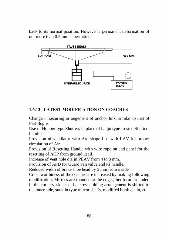
88
back to its normal position. However a permanent deformation of not more than 0.5 mm is permitted.
1.6.13 LATEST MODIFICATION ON COACHES
Change in securing arrangement of anchor link, similar to that of Fiat Bogie. Use of Hopper type Shutters in place of banjo type frosted Shutters in toilets. Provision of ventilator with Arc shape fins with LAV for proper circulation of Air. Provision of Resetting Handle with wire rope on end panel for the resetting of ACP from ground itself. Increase of vent hole dia in PEAV from 4 to 8 mm. Provision of APD for Guard van valve and its handle. Reduced width of brake shoe head by 5 mm from inside. Crash worthiness of the coaches are increased by making following modification; Mirrors are rounded at the edges, berths are rounded in the corners, side seat backrest holding arrangement is shifted to the inner side, sunk in type mirror shelfs, modified berth chain, etc.

89
1.6.14 RIDING INDEX
The assumptions for the formulation of certain standards of assessing comfort is purely from the point of view of vehicle oscillations transmitted to passengers only. The human sensation of comfort is dependent on displacement, acceleration and rate of change of acceleration. Basically, these indices are function of the amplitude of vibration and frequency of vibration. In other words, the product of these values could be used as measure of comfort/discomfort. However the sensation of smooth riding is also affected by other factors like temperature, humidity, noise, dust & various psychological factors experienced by a passenger during run. The ride index is just a number with no units and its value gives us an indication of the riding comfort of a vehicle. The index is easily calculable during field trials by measuring the vertical/lateral accelerations using standard accelerometers. Ride Index gradations are as follows; Riding Index Appreciation Fatigue limit 1.0 Very good >24 hrs 1.5 Almost very good -do- 2.0 Good -do- 2.5 Almost good 13 Hrs 3.0 Satisfactory 5 – 6 Hrs 3.25 Satisfactory with limitations 5 Hrs 3.5 Just satisfactory 2.8 Hrs 4.0 Able to run 1.5 Hrs 4.5 Not able to run 45 minutes 5.0 Dangerous 15 minutes RI criteria applicable on Indian Railways;

90
Preferred limit Max Coaches 3.25 3.5 Wagons 4.25 4.5 Loco 3.75 4.0 EMU/DEMU 4.0 The ride index as described above gives the average riding quality of a vehicle over the chosen length of track (generally one kilometre). However, individual acceleration peaks also have an effect on the comfort of the passengers. Accordingly, limits for maximum acceleration values have also been laid down for coaches and locomotives. For details, the Third Criteria Committee Report of RDSO may be referred. The Following Measures Should Be Given to Maintain Ride Index in ICF coach:- Proper checking of primary suspension arrangement. Checking free height &height variation of primary suspension springs and grouping. Ensuring sufficient level of oil in the telescopic hydraulic dash pot. Gap between safety loop & axle box lug should be within limit i.e. 40 mm. Proper pairing of springs on secondary suspensions. Free height of spring should be within limit. Ensuring proper working of shock absorber. Proper checking of side bearer for oil level & wear on bearing piece/plate should be within limit. Proper checking of silent bushes fitted in bolster for proper matching with centre pivot. Proper checking of buffing gears for buffer face contact. Plunger stroke should not be more than 127 mm & less than 51 mm. All securing bolts & nuts should be properly fitted.

91
Proper checking of draft gear. Coupling should be fully tightened evenly. Other securing nuts, washers, cotters should be in proper position. Anchor links should be intact with good silent block bushes. All break gear pins should be provided with proper bushes. Dynamo pulley & belt should not be loose. It should also be ensured that there is no wheel defect such as flat faces (not more than 50 mm), deep flange, skidded wheel, sharp flange, thin flange etc. In addition, the Ride Index can also be improved by ensuring proper p/way maintenance, signal defects & good engine man ship of the driver.
1.7 CORROSION AND ITS PREVENTION
Introduction: Metals when exposed to environment containing liquids, gases etc. the surface of metal starts chemically reacting with environment and deteriorates. Definition: corrosion is a chemical process of oxidation of metal due to exposure with corrosive environment. Iron exposed to atmosphere and corrosive liquids forms a reddish layer on the surface called rust. Rust is nothing but oxides of Iron formed due to the oxygen available in the atmosphere. Chemical reaction is: 4Fe + 3O2 → 2Fe2 O3 Effect of corrosion: Corrosion reduces the strength of the metal due to reduction in the cross section. With the introduction of all steel coaches corrosion has become a major problem to tackle. Once corrosion starts it spreads rapidly and leads to replacement of the component. This is much costlier than to save the existing part by proper and timely attention.
1.7.1.1 CORROSION IN ICF COACHES:
Corrosion in ICF coaches is very common. Corrosion repairs to coaches are mainly carried out during POH in workshops.

92
Corrosion repairs are also done during midlife rehabilitation (MLR) of coaches when the coach is 12 to 13 years old especially at CRWS, Bhopal. After the MLR, next immediate POH is done after 24 months. During POH all the under frame members are thoroughly inspected for identification of corroded members. Corrosion is indicated by flaking of paint, flaking of metal, pitting and scale formation. Components that is not visible from both sides such as sole bar and trough floor should be examined by tapping with a spiked hammer. Particular attention should be paid to more vulnerable members and locations given below. Sole bars, body pillars, turn under, trough floor and areas below lavatories in all types of coaches and luggage compartments of SLRS. Sole bars, body pillars, turn under and pillars above lifting pads. Sole bars, body pillars behind the sliding doors of SLRS. Inspection of under frame member for corrosion attention should be done as per technical pamphlet no 7602(rev: 1)
1.7.1.2 REASON OF CORROSION IN ICF COACH:
Accumulation of water, dust and salty liquids under luggage compartment in SLR coaches due to insufficient cleaning after unloading perishable items like fish etc. Incorrect fitment of side panels. Seepage of water at corners and ends due to water accumulation on floor. Improper surface preparation before welding. Frequent use of concentrated acids for the cleaning of toilets. Leaky push cocks, flush valves. Missing/defective commode chutes resulting in splashing of toilet discharge leads to corrosion of under frame members. Seepage of water through gaps in window sills. Cracks in body panels and roof.

93
Damage to under frame and trough floor due to flying ballast during run. Spillage of Acid from batteries.
1.7.1.3 NEED FOR PREVENTION OF CORROSION:
Detachment of coaches for corrosion repairs has an adverse effect on the normal composition of trains. In monsoon season seepage of water through corroded panels spoils the consignment and railway will be forced to pay compensation for the damage. Manpower material and time involved in corrosion repairs can be controlled through proper anti-corrosion measures.
1.7.1.4 INSPECTION OF SOLE BARS, BODY PILLARS AND TURN UNDER;
Examine visually and with the help of a spiked hammer from below the coach and the inspection holes in the turn under. If corrosion is suspected at places without inspection holes 100mm dia hole should be cut at the bottom of turn under for examination. If corrosion is noticed in the bottom half of the sole bar the trough floor to be cut to a width of 300mm for inspection. In case of heavy corrosion the side wall to be cut to a width of 500mm.
1.7.1.5 INSPECTION OF HEADSTOCK:
Examine visually inner and outer headstock, stiffening behind buffers and the junction of sole bar and the headstock for corrosion. Examine the base buffer assembly carefully.
1.7.1.6 TROUGH FLOOR:
Examine trough floor adjoining the lavatories and under the luggage compartment of SLRS and Parcel vans for corrosion with tapping hammer.

94
1.7.1.7 CORROSION REPAIRS DURING POH
1) Repairs to under frame members: Repairs to under frame members should be carried out as per RDSO pamphlet no C7602 for ICF coaches. Corrosion resistant steel sheet for trough floor, pillars, sidewalls and roof should confirm to IRS M-41-97. Electrode shall be IRS class B2 of approved brands. Paint red oxide zinc chromate primer should confirm to IS-2074-62. Bituminous anti corrosive solution to IRS-P30-96. 2) Repairs to Headstock: Only 8mm thick sheet is to be used for headstock repairs. 3) Repairs to Sole bar: The new sole bar section to be welded from both inside and outside. 4) Repairs to Side Wall Members: For repairs to side and end wall members, interior fittings interior panels & window frames are to be stripped. Repairs to be done as per RDSO sketch No. 76019. 5) Repairs to Trough Floor: For trough floor repairs plywood flooring to be stripped. Repairs to be done as per RDSO instructions. 6) Repairs to Roof: Special attention to be paid at locations where gutter mouldings are welded and where ventilators are fitted. RDSO instructions to be followed
1.7.1.8 MIMINISING THE OCCURANCE OF CORROSSION
Corrosion in rolling stock cannot be eliminated altogether. Hot and humid atmospheric conditions in our country are contributory factor for corrosion. Change in climate also has an adverse effect. However timely attention during repairs and maintenance will minimize corrosion. A) DURING POH

95
Thorough inspection shall be done giving extra attention to areas prone to corrosion. Turn under repairs to be carried out with 5mm thick plates. Only 8mm thick SS sheets to be used for head stock repairs. Use stainless steel trough floor and inlays for toilets. Use 13mm compreg floor board instead of plywood. Use PVC sheets for toilets and compartment floor. Use stainless steel plates with drain holes in doorways. Provision of tubular structure below lavatory area. Corten steel only to be used for panel repairs. Apply two coats of primer and three coats bituminous solution on all under gear members. B) IN OPEN LINE During pit line examination check thoroughly all under gear and under frame components, trough floor and headstock etc. for corrosion. If corrosion is noticed, take proper anticorrosive measures. Drain holes and drain pipes should be clear so that water stagnation is eliminated. All water leakage to be arrested at the earliest. Ensure that the damaged PVC flooring is repaired without any delay. Ensure that the gaps in window sill are filled up to avoid seepage of water. Deficient/defective commode chutes to be made good. Flushing of water inside the coach for cleaning to be avoided. Avoid strong acids for toilet cleaning. Body patches to be painted, carry out paint touch-up where paint is peeled off. During IOH all vulnerable areas are to be properly inspected after Cleaning of turn under holes. Procedure for applying anti corrosive paint in coaching stock. 1st coat ------- zinc chromate 2nd coat ------ zinc chromate, red oxide

96
3rd coat ------- bituminous thin black solution 4th coat ------- Bituminous red brown solution 5th coat ------- Bituminous primer thick black 6th coat ------- bituminous primer silver grey Exterior paint schedule for coaches At every 5th POH of a coach or if the condition of paint is not good adopt 9 days painting schedule. (A—schedule) otherwise choose 5days paint schedule. A—schedule (9—days) 1st day – Remove old paint 2nd day – One coat of red oxide zinc chromate primer 3rd day – One coat of brush filler followed by spot putty 4th day – Filler 2nd coat (spot putty if necessary) 5th day – Rub down with silicon carbide paper 6th day – One coat of under coat 7th day – Flat with silicon carbide paper. One coat of enamel finishing. 8th day – Flat with silicon carbide paper. 2nd coat of enamel finish 9th day – Lettering and miscellaneous work C --- Schedule 1st day – Washing with soap solution touch -up damages with primer 2nd day – Spot putty if necessary and one coat of under coat 3rd day – Flat with silicon carbide paper apply one coat of finishing Enamel 4th day – Flat with silicon carbide paper apply second coat of Finishing enamel. 5th day – Lettering and miscellaneous work
1.7.1.9 SUGGESTIONS TO PREVENT CORROSION:
Supervisors involved in maintenance of rolling stock should be familiar with areas prone to corrosion.

97
Supervisors should educate their technicians about areas prone to corrosion. Identify corrosion prone areas and inspect them thoroughly during pit line examination, sick line attention, ROH/IOH. Suitable preventive measures to be adopted to save the affected component. In case of heavy corrosion replace the component. Painting/ paint touch-up during IOH and sick line attention. Supervisors should educate their cleaning staff so that they follow proper cleaning technique. Ensure water tightness of covered wagons. Educate Shunting staff so that they perform smooth shunting without damaging the rolling stock Electrical staff to be counselled about the corrosive effect of acids from batteries. These small steps will go a long way in minimizing corrosion in rolling stock.

98
2 LHB – COACHES
2.1 Introduction to LHB Coaches
(Linke Hoffmann Busch GMBH – German)
Indian railways have been manufacturing passenger coaches of “Schlirien” design for more than 50 years. Although continuous efforts were being put to upgrade these coaches, due to constraints/limitations in the design, we could not cope up with quality and speed of the Railway transport in the developed countries. It was felt to imbibe technology in-use, in the developed countries so as to effect a quantum jump in quality and speed of Railway coaches. “M/s Alstom and Linke Holfmann Busch (LHB)” are one of the leading manufacturers in transport sector having presence in most of the European countries. Coaches manufactured by them are running in many countries across the world.
99
LHB coach body is designed and manufactured by leading German company Linke Holfmann Busch GMBH and Bogies for these coaches is designed and made by M/s FIAT, Switzerland which is now a part of Alstom group. Indian Railways entered into a TOT agreement with M/s. Alstom Germany for manufacture of LHB type of Coaches. Accordingly, their inception and mass production in Railways started in 2002 and population is growing day by day. BENEFITS TO RAILWAYS A longer coach: LHB coaches are approximately 1.7 meters longer than the conventional ICF type coaches. This means “more travel space”, “increased seating capacity”, “wider bays and doorways” etc. A lighter coach: Weight per meter length of LHB coach is approximately “10%” lesser than the conventional coach. This not only means lower haulage costs but also less wear and tear of the coaches and track. A higher speed coach: LHB coaches are designed to run at a maximum speed of 180 kmph. Even for speeds of 200 kmph, no major changes are required. Lesser maintenance, due to use of superior materials with longer life. Wheel slide protection (WSP) system based on microprocessor. It detects the variation of speed between the 4 wheels of the coach and if any wheel is rotating at a lower speed, the particular wheel brake is released automatically. This protects the wheel from skidding. Bogie with less moving parts. Items of wear & tear do not require replacement/renewal before 10 lakh km. Entrance doors flush with side wall allowing automatic car washing. BENEFITS TO THE PASSENGER

100
Better ride quality with improved ride comfort - ride index reduced from over 3. 0 to 2. 5 at a speed of 160 kmph. Plush interiors comparable to international standards. Improved air-conditioning through better duct designing & humidity control. Bigger size sealed windows filled with “argon” gas for a panoramic view & better heat insulation. Modular “oriental” & “western” style toilets with Controlled discharge toilet system (CDTS) This system works on electro- pneumatic principle where in, the waste generated from the coach lavatories during run is collected in a retention tank and is disposed off away from the station limits and avoid soiling of station premises. Well equipped pantry with hot cases, deep freezer, bottle coolers etc. Flush type swiveling berth reading light.

101

102
SAFETY RELATED PROVISIONS; Four emergency exit windows for faster passenger evacuation during emergencies. Wider vestibule designs for smooth inter coach movement with luggages. Convenient to operate emergency alarm pull operation. Fire - retardant furnishing. Tight lock centre buffer coupler gives anti-climbing feature, during accident. Crashworthiness, leading to lesser injury to the occupants of the coach during accidents.
2.1.1 Salient Features of LHB Coaches
These coaches are longer by 1.7 meters than the ICF coaches and hence more number of passengers can be accommodated in a given coach. As the length of the coach is longer the number of coaches required to form a formation is reduced and hence over all cost of maintenance becomes less. These coaches are fitted with Axle Mounted Disc brakes to have an effective brake power to stop the train within the short braking distance. As the brake forces are acting on the Discs which are mounted on the Axles, the wear on the wheel tread caused due to brake application on tread is eliminated and hence the life of the wheels are considerably increased.

103
These coaches are fitted with Wheel slide protection device to prevent the wheel from getting skid. Due to various reasons it is possible for any one of the wheel to have lesser speed when compared to the other three wheels and in such a case it releases the air from the brake cylinder of the affected wheel automatically to prevent the wheels from getting skid These coaches are fitted with Brake accelerator in the Brake pipe to bring BP pressure to zero during emergency brake application. The brake accelerator connects the Brake pipe with exhaust during emergency application to facilitate faster exhaust of air from the brake pipe. These coaches are provided with FIAT bogies, which are designed to run at a speed of 160 KMPH. The wheelbase of Bogie is 2560 mm. These coaches are fitted with earthling device to prevent damages to the Roller bearings. These coaches are fitted with roof mounted AC package units. These coaches are fitted with Controlled discharge Toilet system designed to discharge the human waste when the speed reaches above 30 KMPH. The objective of this toilet system is to keep the station premises clean and hygienic. These are fitted with tight lock AAR centre buffer coupler with anti-climbing feature to prevent the climbing of one coach over another in case of accidents.

104
The following equipments are operated by Microprocessor controlled system Wheel slide protection device. Controlled discharge toilet system. Water pumping device. Roof mounted AC package units The riding index of LHB coach is 2.75 when compared to 3.25 in case of ICF Coaches. Up-graded design for passenger safety/comfort like; Ergonomically designed seats as per Indian anthropometrics data, Large windows with good visibility, Luggage racks with in-built reading lamps, Insulation against noise, No visible screws in the interior, Use of fire retardant materials, Hand – safe feature in all automatic sliding doors, Anti – skid PVC flooring, UIC vestibules and auto - closing vestibule door, Functionally designed pantry area, Easily accessible AC unit controls. The passenger emergency alarms signal devices (emergency alarm pull box) are provided inside passenger compartment. This is to avoid operation of PEASD by unauthorized persons from outside. There is no mechanical linkage like a chain and this handle directly operates the PEA valve for venting the brake pipe pressure

105
2.2 DESIGN FEATURES OF LHB COACHES
Description LHB Coach ICF Coach Length over body 23540 mm 21337 mm Length over buffers 24000 mm 22297 mm Overall width 3240 mm 3245 mm Overall height 4039 mm (AC 3
tier 4250 mm) 4025 mm
Max distance between inner wheels
12345 mm 11890 mm
Distance between centre pivots 14900 mm 14783 mm Window opening 1180 x 760 mm 1200 x 550
mm Height of compartment floor from Rail level under tare
1303 mm
Max CBC drop under gross load and worn conditions
75 mm
Minimum height from Rail level
102 mm
Max height (empty) 1105 mm 1105 mm Minimum buffer height (loaded)
1030 mm 1030 mm
Wheel base 2560 mm 2896 mm Wheel dia (New) 915 mm 915 mm Wheel dia (Cond) 845 mm 825 mm Speed potential in kmph 160 upgradeable to
200 140 max
Max Axle load permissible 16 t Ride index 2.5 to 2.75 3.25 Speed Potential (Kmph) 160 140 Axle Box Guidance Articulated Rigid Dampers-Primary Hydraulic Dashpot
Bogie Frame Without Headstock With Headstock

106
2.2.1 COACH SHELL
The entire shell is made from stainless steel and low corrosion steel. All the structural elements with section thickness above 5mm and more are made from Corten steel. Trough floor and roof panels are made from Austenitic stainless steel. Other structural members and side members and sidewall panels are made from ferritic stainless steel. The shell design eliminates turn-under and other pockets causing corrosion in conventional coaches.

107
Various types of steels used in construction of LHB Coaches
The C – Shaped section Sole bar is used in the LHB coaches when compared to Z-shaped in ICF coaches
Special Design feature of LHB coach flooring; 16 mm composite board made from cork panels glued to “Makore” wood have been used. Flooring panels are lightweight, strong, warp resistant and also resistant to vibrant/impact forces. These floors are specially treated for fire resistance; these are also resistant to moisture, cigarette burns, staining, aging etc. The intermediate cork layer imparts nice insulation characteristics to the floor panel. The “floating” floor is supported by rubber- metal decoupling elements, for absorption of structural vibrations. Inter-locking joints of vertical & horizontal members is adopted for structural joints
Shell Assemblies Steels Used Composition Side Wall, End Wall And Roof structure
Ferritic Steel X2 Cr8
C-.03%, Cr-10 to12% Si-1%, Mn-1.5%
Roof Sheet and Trough floor
Austenitic Steel X5 CrNi18-10
C-.07%, Cr-18% Ni-10%, Si-1%, Mn-2%
Under Frame Corten Steel IRS-M-41
C-.01%, Cr-.35 to.6% Ni-2 to 4 %,Si-0.3to0.7%, Mn-0.25%

108
2.3 FIAT BOGIE.
The LHB coaches are provided with the FIAT bogies to run at a speed of 160 KMPH.
2.3.1 Limitations of ICF all Coil Bogie
The longitudinal and lateral movements of the wheels cannot be controlled independently as generally required for High-speed bogies. Since there is vertical space constraint between the top and bottom bolster, it is not possible to provide softer secondary suspension springs which are required for the high speed trains to control the dynamic movements of the bogie bolster and coach body. Headstocks increase the yaw inertia of the bogie frame and thereby, influence the tendency for hunting. The wheelbase of ICF all coil bogie is 2896 mm. This large wheelbase affects curve negotiations and thereby increases wheel flange wear. Since the brake forces are offered on the wheel tread by clasp brake, it could not give sufficient retardation during brake application which in turn increases the emergency braking distances. The life of the wheel is also reduced due to tread wear.
2.3.2 Technical parameters of FIAT Bogie
Bogie width 3030 mm Bogie length 3534 mm Bogie weight 6300 Kgs Wheel base 2560 mm Wheel diameter (New) 915 mm Wheel diameter (Cond) 845 mm Wheel distance 1600 +/- 1 mm

109
This is a two axle bogie with both primary and secondary suspension. The Bogie frame is made of two longitudinal solid welded component connected by 2 cross beams which also supports the brake units. This frame rests over the primary suspension and the weight of the coach body is taken by the bogie through the bolster beam and the secondary suspension.

110
Primary suspension is at 4 points over the axle-bearing box. Each unit has 2 coil springs (inner and outer) with a vertical damper and a control arm fitted with twin-layer elastic joints connecting the bearing to the bogie frame.
Secondary suspension enables lateral and vertical displacements and also bogie rotation with respect to body when negotiating curves. It is provided on both the bogie frame longitudinal. Each unit of suspension has 2 steel coil springs (internal and external), which carries the Bolster beam with a vertical damper and a lateral damper. 4 nos. of safety cables are connected between the bolster beam and the cross beam. 2 YAW Dampers are also connected between Bogie frame and the Coach Body. Traction centre transmits both tractive and braking force between the body and the bogie. It comprises of a Traction Lever which is connected to the cross beam of the bogie frame by means of 2 Traction Rods diagonally with elastic bushed joint. For limiting the longitudinal and lateral displacement of the bolster beam, there are 2 Lateral and 2 Longitudinal Bump stops fitted on a support frame and the support frame is fitted to the Bogie Frame.

111
On two outer corners of the Bogie Frame nylon roller is fitted by a pin, which prevents excessive rotation of the bogie with respect to body. Anti roll bar is fitted between the bogie frame and the Bolster Beam to maintain the Coach body always parallel with the bogie, even while negotiating curves. Dampers Used in the FIAT Bogies Dampers used in FIAT bogies are hydraulic shock absorbers (confirming to UIC 515-4) to damp the oscillations caused due to track irregularities. Following dampers are provided on each bogie: Four vertical dampers are provided in primary suspension between axle box and bogie frame for absorbing the shocks between the wheel and the bogie frame. Two vertical dampers are provided in secondary suspension between bogie frame and bolster to cushion the vertical movement and one lateral damper is provided to cushion lateral movement. Two numbers of Yaw dampers are provided between bogie frame and coach body to cushion the yaw and longitudinal movement.

112
The wheels are provided with Catridge type tapered roller bearings. On each axle 2 discs (640 mm dia) are fitted between the wheels for brake application. Brake calliper assembly along with brake cylinders are fitted on the cross beam and brake pads are used to have contact with the discs for brake application. One end of each axle is fitted with speed sensor used for the Microprocessor input of Wheel Slip Protection device.
2.3.3 Wheel Slide Protection device:
In LHB coach pneumatically controlled Disc brake system is used. During brake application, factors like variation of co-efficient of friction (due to composition of brake pads and disc) and adhesion between rail and wheels and various other factors may cause difference in RPM (rotation per minute) of axles on the same coach. This may lead to wheel skidding/ flat tyres. To prevent this, a Wheel Slide Protection (WSP) device is provided in these coaches.


114
Main Components and their functions: Part No Name Qty Function
1. Micro Computer
1 Per Coach
Gets input from speed sensors, compares with reference speed and gives output signal to Rapid Discharge Valve to open or close in case of variations.
G-I & G-2
Speed Sensor 1Per Axle
It consists of a fixed Magnetic Resistor (MR) and a Phonic Wheel (P) having 80 teeth, fitted on the axle. It gives tachometric pulse signal to Micro Computer due to variation in air gap (A and A +X) between the phonic wheel and the magnetic resistor.
3.
Rapid discharge valve (dump valve)
1 Per Axle
It is an Electro-Pneumatic Valve which is connected in series with the Brake Cylinder (BC). It regulates the BC (Part No-4) Pressure by disconnecting the DV from BC and also by connecting the BC with atmosphere when the output signal is received from Micro Computer.

Principle of working; The rotation of each axle is constantly measured and compared with a reference speed (The RPM of the fastest wheel of the coach) for that coach. In case there is a variation in RPM among the wheels, WSP automatically releases the brakes of the wheel with slower speed accordingly, so that the RPM of all the wheels become uniform. Working: The limit of variation of speed and acceleration are defined as threshold values. The Micro Computer constantly compares the signals from the speed sensor mounted on each axle with the reference speed. If the speed/ acceleration of any axle is crossing the present threshold values, it gives signal to the respective Rapid Discharge Valve to release the BC pressure accordingly, thus maintaining the speed/acceleration with in the threshold level.
2.3.4 Advantages of LHB coaches
Better payload to tare ratio. Better safe guard for corrosion. Increased coach availability due to reduced maintenance Higher carrying capacity of 78 passengers in chair car
2.4 Air Brake Testing Procedure for LHB Coaches:
On arrival of the rake on pit line, completely drain the AR tank (125 litres & 75 litres) of all the coaches by opening the drain cock, to remove the water in air. Initially, couple the BP hose of the test rig with the BP hose of the rake & then charge the BP pressure to 5.0 kg/cm2. Keep the FP angle cock of both end power cars in close position. Check the FP gauge fitted in the power car, if the gauge does not show any pressure, the NRV of all the coaches are ok. If, FP gauge shows any pressure, the NRV of some coach in the rake is defective. In

116
this condition, check the rake for NRV defective by taking the coaches in parts. NRV found defective in particular coach should be replaced. Open all the four cocks of rake, couple BP & FP hose pipe of test rig with the BP & FP hose pipe of the rake. Charge the BP & FP to 5.0 kg/cm2 & 6.0 kg/cm2 respectively. After building of pressure in BP & FP, disconnect the test rig BP & FP hose pipe from the rake hose pipes & open both the angle cocks, due to which air pressure will be exhausted in atmosphere & brake will be applied. Wait for 20 to 25 minutes. After 20 to 25 minutes, check the complete rake from one end. Note down the coach nos. found with released brake cylinder. Check whether, AR tank of the coach is charged or empty. If AR tanks found empty, write down Empty AR on the respective coach. If found charge, pull manual release of DV to check whether CR tank is charged / empty. If CR found empty, write down Empty CR on respective coach. With this, all the defects in the rake can be checked. Again, connect BP & FP hose pipe of the rake & test rig & then charge BP to 5.0 kg/cm2 & FP to 6.0 kg/cm2. Connect BP & FP gauges with dummy on free end of other end power car. Check the BP & FP pressure gauges in front power car, BP pressure should show 5.0 kg/cm2 & FP pressure should show 6.0 kg/cm2. If there is any difference in any pressure, check by fitting master gauge if still the pressure is not showing 5.0 kg/cm2 in BP & 6.0 kg/cm2 in FP, check for leakage & attend. Close the BP & FP angle cock of test rig for 03 minutes. Monitor the leakage in both BP & FP. The leakage should not be more than 0.6 kg/cm2 in 03 minutes.

117
Attend the coaches in which AR empty & CR empty are found. Check the AR tank & pipe line from the back of the brake panel for leakage. Similarly, check CR tank & pipe line & dummy plug on the brake panel. If defect is still noticed after attending the leakage, then mark the coach sick for detailed investigation & single car testing in sick line. Start the pressure & charge the BP to 5.0 kg/cm2 & FP to 6.0 kg/cm2. Drop the BP pressure by 1.6 kg/cm2, brake should apply in all coaches. Start the leakage checking with the help of soap solution from one end. During soap solution testing, check all the BP & FP hose pipe, all hose pipe connectors, Main pressure pipe line, Angle cocks, Brake cylinder pipe line, CDTS pipe line. Similarly, check & attend leakage in components on Brake panel like DV, FP & BP filter, NRV, all isolating cock, brake indicator, brake accelerator & brake cylinder with soap solution. Isolate the isolating cock on Brake panel & check all brake callipers & brake pad of all cylinders. In isolated condition, all brake pads should be released simultaneously. Similarly, on opening of isolating cock all Brake cylinder should operate & brakes should apply. Check the brake indicator when brakes are applied, indicator should display red colour. However, when the brakes are released from isolating cock the brake indicator should display green colour. If on brake release condition, brake indicator is not showing green or on brake applied condition brake indicator is not showing red, then the brake indicator is defective. Repair / replace the brake indicator. The BP & FP pressure gauges in the others end power car should show pressure 3.4 kg/cm2 & 5.8 - 6.0 kg/cm2 respectively. If any difference in above pressure is noticed that means there is any

118
cross connection in BP & FP connection. Attend the same & ensure BP pressure 3.4 kg/cm2 & FP pressure 5.8 - 6.0 kg/cm2. Charge the BP & FP pressure to 5.0 kg/cm2 & 6.0 kg/cm2
respectively. Check the brake indicator of complete rake, all coaches should be in released condition. If any coach is not released, it means that the CR of that particular coach may be overcharged & there is an internal defect in DV. Mark the coach sick for detailed investigation. Check PEASD of at least 03 coaches. During PEASD checking, brakes should apply in all coaches & the brake accelerator should operate. Coach numbers should be noted in maintenance diary. Now close the pressure supply from the test rig. Operate the emergency guard van valve of front power car guard van. BP pressure should become 0.0 kg/cm2 in approx. 25 to 30 sec in front power car & approx. 40 to 50 sec in rear power car. Open the pressure supply & charge BP & FP to 5.0 kg/cm2 & 6.0 kg/cm2
respectively. Now again close the pressure supply from the test rig. Operate the emergency guard van valve of rear power car guard van. BP pressure should become 0.0 kg/cm2 in approx. 25 to 30 sec in rear power car & approx. 40 to 50 sec in front power car. Check for any significant difference in time for droppage of BP pressure to 0.0 kg/cm2 between front & rear power cars. If any, there may be blockage in BP line of any coach. If found, attend the same. Continuity test of the rake is now completed. In both the power cars, check the condition & mounting of hand brake cables fitted on both the brake cylinders. Rotate the hand wheel fitted in guard van clockwise to apply the brakes, after full rotation brake should apply in both the brake cylinders & hand brake indicator should show red. Rotate the hand wheel anti

119
clockwise, now brakes of both the cylinders should get release & hand brake indicator should show green. Charge the BP & FP to 5.0 kg/cm2 & 6.0 kg/cm2 respectively. Close the BP & FP angle cock of test rig for 03 minute. Monitor the leakage in both BP & FP. The leakage should not be more than 0.6 kg/cm2 in 03 minutes. Isolate the isolating cock of BP & FP of the test rig & angle cock of BP & FP of the cock. Uncouple both hose pipes & open both the angle cocks of coach. After draining of pressure from both the BP & FP hose, release the complete rake by pulling the manual release handle of the DV of each coach & ensure the brake indicator of all coaches should display green colour. Ensure that all BP, FP & BC gauges fitted in power car are calibrated & showing correct reading. WSP Testing Initially with no pressure, the WSP processor in all the coaches should be OFF. If any processor is in ON condition, there is problem in any of pressure switch, wiring or K-05 relay. Attend the same. Start the BP & FP pressure. The processor should automatically ON when BP pressure reaches 1.6 to 2.0 kg/cm2 in M/s KNORR WSP system & when FP pressure reaches in M/s FTIL WSP system. Check & attend for loose/proper fitment of WSP components like speed sensor, junction box, dump valve, dump valve connector & pressure switch. Drop the BP pressure by 1.6 kg/cm2, brake should apply in all the coaches. Now check the WSP processor for correct reading ‘99’ on

120
the electrical panel inside the coach. If the reading shows ‘99’, it means that the WSP system is OK. Operate the test button on the processor to check the proper working of dump valves. The dump valve should operate in a sequence & pressure should be exhausted from brake cylinder. If the dump valve is not operated in proper sequence attend the same. Similarly, check & attend the WSP system of all the coach. All the WSP system should be in operating condition in the rake.
2.4.1 Single car test procedure
BP 5 ± 0.1 kg/cm2 pressure FP Specified 6 ± 0.1 kg/cm2 Please ensure that all the pipe fittings, brake equipment are properly fitted and in place before starting the testing.
Item Test Parameters Specified value 1.0 1.1 1.2 1.3 1.4 1.5
Reservoir Charging Charging time of AR (0 – 4.8 kg/cm2) Charging time of CR (6.0 litre) (0 – 4.8 kg/cm2) BP Pressure CR Pressure FP Pressure
175 ± 30 sec.(FTIL) 60 to 120 sec.(KB) 165 ± 20 sec.(FTIL) 160 to 210 sec.(KB) 5.0 ± 0.10 kg/cm2 5.0 ± 0.10 kg/cm2 6.0 ± 0.10 kg/cm2
2.0 2.1 2.2
Sealing test (Allow the system to settle for 2 min. after charging BP & FP. Observe the rate of leakage). BP (Less than 0.1 kg/cm2 in 5 minutes) FP (Less than 0.1 kg/cm2 in 5 minutes
< 0.1 kg/cm2 < 0.1 kg/cm2
3.0 3.1 3.2 3.3 3.4 3.5 3.6
Full Brake Application Reduce BP from 5.0 to 3.4 kg/cm2 Brake Accelerator Maximum BC pressure Leakage in BC Pressure within 5 minutes All brake cylinders Both side Brake indicators
Brake should apply with in 3 – 5 Sec. Should not respond 3.0 ± 0.1 kg/cm2 < 0.1 kg/cm2 Should be Applied Should show Red
4.0 4.1 4.2 4.3
Release after Brake Application Charge BP ( up to 5.0 kg/cm2) All brake cylinders Both side Brake indicators
5.0 ± 0.1 kg/cm2 Should be Released Should show Green
5.0
Over Charge Protection Check the overcharging of CR it should not be overcharged more than 0.1 kg/cm2 in 10 second.
Less than 0.1 kg/cm2 in 10 sec.
6.0 6.1 6.2
Emergency Application Reduce BP to 0 kg/cm2 Brake accelerator should respond
0 kg/cm2 blast of air

121
6.3 6.4 6.5 6.6
Charging time of brake cylinder (0 – 3.0 kg/cm2 ) Max. brake cylinder pressure All Brake Cylinders Both side Brake indicator window
3 – 5 Sec. 3.0 ± 0.1 kg/cm2 Should be Applied Should show red
7.0 7.1 7.2 7.3
Release after emergency Brake application BC release time (from 3.0 kg/cm2 to 0.4 kg/cm2) All Brake Cylinder Both side Brake indicator window
15 - 20 Sec. Should be Released Should show Green
8.0 Graduated brake application and Release Graduated brake application and Release (Minimum 7 steps)
Brake should apply & release corresponding to decrease & increase of BP Pressure.
9.0 9.1 9.2 9.3
Test for Pressure switch for Anti skid device Charge the Feed pipe/Brake pipe* pressure Anti skid device Anti skid device
* For FTIL - FP & For KBI - BP.
Ok Should get power supply at 1.8 ± 0.2 kg/cm2 Power supply should cut off at 1.3 ± 0.2 kg/cm2
10.0 10.1 10.2 10.3 10.4
Isolation Test Close the isolating cocks for Bogie –1 & 2 Reduce BP pressure to full brake application Both side Brake indicators Open both isolating cock
Brake should not be applied Should show Green Brake should apply corresponding to opening of isolating

122
10.5 10.6 10.7
Both side Brake indicators Again close the Isolating cock of bogie 1 & 2 one by one. Both side Brake indicators of bogie 1&2
cock for bogies Should show Red Brake should Release Should show Green one by one
11.0 11.1
Sensitivity Test Reduce the BP pressure at the rate of 0.6kg/cm2 in 6 seconds.
Brake should apply within 6 sec
12.0 12.1
Insensitivity Test Exhaust BP pressure at the rate of 0.3 kg/cm2 Per minute
Brake should not be applied.
13.0 13.1 13.2 13.3 13.4 13.5 13.6 13.7
Passenger Emergency Pull Box testing Pull the emergency pull box handle & check Brake accelerator Check BP Pressure exhaust from emergency brake valve Indicator Lamp on out side the coach Both side Brake indicators After resetting, check exhaust from emergency brake valve Both side Brake indicators shows Green
BP pressure should remain at 2.0 ± 0.2 kg/cm2 Should respond Should exhaust Should glow Should show Red Should stop Green
14.0 14.1 14.2 14.3 14.4 14.5 14.6 14.7
Hand Brake test (Power car only) Apply hand brake by means of wheel Both side Hand Brake indicators Check Brake Cylinders provided with hand brake lever Movement of flex ball cable Release hand brake by means of wheel Check the Brakes Both side Hand Brake indicators
Should work smoothly Should show Red Should be Applied Yes Should be proper Should work smoothly Should release Should show green
15.0 15.1 15.2 15.3 15.4
Emergency brake by guard van valve (Power car only) Drop BP Pressure by means of guard valve Brake accelerator should respond Both side Brake indicators Hand Brake indicators Reset guard van valve
Brake should Apply Blast of air Should show red Should show green Brake should releases
16.0 16.1
Manual release test Apply full brake application and pull manual release wire of DV; it should be released in one brief pull of Manual release valve.
CR Drops to zero, Brake releases.
17.0 17.1 17.2 17.3 17.4 17.5
WSP test Check the Speed sensor air gap between sensor and Phonic wheel by means of feeler gauge. (At least at four different locations) Charge the BP/FP Pressure at full specified value. Check the WSP Micro Processor Check the WSP Micro Processor code. Check the Dump Valve venting by test mode
KB - 0.7 to 1.5 mm FTIL -1.5 to 2.5 mm Should activate at 1.8 ± 0.2 kg/cm2 Should show code 99 Should vent one by one in proper sequence
18.0 Check clearance between brake disc & brake pad 1.5 mm

123
3 MODERN COACHES
3.1 DEMU COACHES
The special features of High Horse Power DEMU coach; These coaches are fitted with Air springs in the secondary suspension to maintain a constant buffer height irrespective of loaded condition to give comfortable riding to the passengers.
Bottom bolsters, Stirrup links and Equalising stays are eliminated Schaku couplers are provided and Side buffers are eliminated. It is provided with an emergency spring inside the air spring to support the bolster in case air spring fails.
3.1.1 Air Spring
Air spring is a rubber bellow containing pressurized compressed air with an emergency rubber spring providing various suspension characteristics to maintain a constant Buffer height irrespective of the loaded condition.

124
In suburban trains like DEMU, the number of passengers entraining (Super Dense Crush Load) in to the coach cannot be controlled and hence the payload of the coach increases from 18 tons to 34 tons. This abnormal increase of payload reduces the Riding Clearances between the Coaches and Wayside platforms and also reduces buffer height resulting in severe hitting of coach on the plat forms. Due to the Super Dense Crush Load the bolster springs become solid, which in turn damages / breaks the Coil springs resulting in discomfort to the passengers. To overcome the above problems an Air Suspension (Air spring) is introduced in the secondary suspension to maintain a constant buffer height irrespective of loaded conditions by varying the pressure of air inside the air spring.

125
3.1.2 Components of Air Suspension
Air spring, Emergency spring, Levelling valve, Adjustable screw rod, Duplex Valve, Main Air Reservoir, Auxiliary Reservoir, Isolating Cock

126


Levelling valve: The leveling valve is fitted with Top bolster and is designed to move up and down along with bolster. Under normal condition, it is designed to take LAP position when the actual buffer height is equal to the required buffer height.
The function of leveling valve is to connect the main reservoir with the air spring to admit more air in to the Air spring, whenever the actual buffer height is less than the required buffer height due to abnormal increase in the Pay load (Super Dense Crush load).

129
It also connects the air springs with exhaust to release the excess air from air spring, whenever the actual buffer height is more than required buffer height due to reduction in the Pay load after detraining of passengers from the coach
Installation lever: It is fitted between the levelling valve and bottom of the bogie frame. The function of installation lever is to operate the levelling valve automatically by moving the handle of the levelling valve up and down according to the condition of the load. The up and down movement of handle of levelling valve admits the compressed air in to the Air spring or releases the compressed air from the air spring through levelling valve in proportion to the pay load of the coach. Duplex Valve: It is a double check valve provided between the two Air springs of the same bogie. It operates with a Pressure differential of 1.5 bar. Basically it comprises of two check valves side by side, arranged so that air can flow in either direction whenever the air

130
pressure differential exceeds the pre-set value of 1.5 bar. Whenever a burst of air spring occurs on one side, this valve will ensure that no severe tilt or twist occurs during movement of the coach. Both the check valves of Duplex valve remains closed, if the pressure between the two springs is within 1.5 bars. When the differential air pressure exceeds the preset value, the air at higher pressure overcomes the spring pressure and flows to the lower pressure via the check valve. The flow continues till the differential reaches the preset value. In case of burst of Air Spring, the air leaks to atmosphere. Due to high-pressure differential, the Duplex check valve releases the air from the intact air spring through burst air spring. Thus complete coach will gradually come down and rest on the emergency rubber springs. Auxiliary reservoir of Air Spring: It is fitted with the Air spring. The capacity of this reservoir is 20 Ltrs. There is an orifice kept between air spring and additional reservoir. It acts as an Air damper to over come vertical and lateral oscillations so as to increase the riding comfort. Main Air reservoir: The capacity of the main reservoir is 150 ltrs and it is exclusively used for feeding the compressed air in to the Air Spring. Emergency Springs: The function of emergency spring is to support the top bolster to prevent tilt of coaches whenever the Air spring burst.
3.1.3 Comparison of Helical coil springs with Air Springs.:
Unlike steel springs, air springs retain their height under changing loads. The low natural frequency of air spring suspension remains virtually constant.

131
In case of coil spring, deflection is proportionate to the load. Therefore under high payload situation, space constraint becomes critical, leading to the use of stiffer springs resulting in unsatisfactory ride behaviour and reduced speed potential. Air springs through their control mechanism offer a load proportionate stiffness, constant floor height and better ride behaviour with higher speed.
3.1.4 Advantages of Air Suspensions
Capable to sustain Super Dense Crush Load of suburban traffic at high speeds. It maintains a Constant floor height of coach. It facilitates excellent riding comfort with riding index of 2.5. Safe running due to the excellent Air Damping. Low design height. Unusual noise emitted due to hitting of coaches on the plat forms is eliminated.

132
The Stirrup links, Coil springs and equalizing stays are eliminated and therefore easy to maintenance.
3.2 Double Decker Coaches
Double Decker coaches are manufactured in RCF. These coaches are AC coaches These coaches are provided with FIAT Bogie having air spring in the secondary suspension These coaches height is 113 mm more than ordinary coaches at top centre Seating capacity is 120 seats (only chair car) Provided with Type ‘H’ tight lock CBC coupler These coaches are provided with four toilets with CDTS These coaches are provided with FIBA (Failure Indication & Brake Application device)
4 AIR BRAKE
The brake system in which compressed air is used in the brake cylinder for the application of brake is called air brake. Competition from other form of transport has warranted the Railways to run trains at higher speed, heavier load etc. to achieve this better and reliable braking is required. The vacuum brake has got its own limitations like brake fading, increased application and release timings etc., In practice it is not reliable to run trains in higher altitudes due to insufficient vacuum levels in brake van and train engine. Hence to overcome the above problems, it has become necessary to introduce Air brake system to control the speed of the train and to stop it within a reasonable distance, irrespective of length, load of the train, distance covered and altitude of the train. Advantages of Air brake over Vacuum brake system

133
Uniform brake power is possible throughout the train in air brake, but it is not possible in case of vacuum brake, since the pressure drop at the rear of the train is up to 20%. The propagation rate of compressed air is 260 m/sec to 280 m/sec. when compared to 60 to 80 m/sec. in the case of vacuum brake. The Air brakes have potentiality to run trains longer than 600 metres length. The air brake trains have potentiality to run heavier trains than 4500 tons, Shorter braking distance, Suitable for higher altitudes, Compact and Easy to maintain, Consumption of spare parts is very less, Simple brake rigging, Quicker application and release, so better punctuality can be achieved, Better utilisation of rolling stock since less maintenance and pre departure detention. Differences between Air Brake and Vacuum brake Sl. No.
Air Brake Vacuum Brake
1. Air brake works on compressed air at 5 Kg/Cm2 maintained in brake pipe
Vacuum brake works on atmospheric pressure at 1.03 Kg/Cm2
2. At the time of brake application compressed air is admitted in to the brake cylinder up to a max of 3.8 Kg/Cm2
In vacuum brake air at atmospheric pressure is admitted
3. Distributor valve is the main functioning unit in the air brake system
Vacuum cylinder is the main functioning unit in the vacuum brake system.
4. Brake application is caused by the outward movement of the piston
The inward movement of the piston causes brake application.

134
5. Brake cylinder is connected to auxiliary reservoir during brake application and to exhaust during brake release through the distributor valve.
Vacuum cylinder is directly connected to train pipe during brake application and release.
6. For any reason, if the cylinder has to be made inoperative, it can be conveniently done by closing the isolation cock.
For any reason if the cylinder has to be made inoperative, the train pipe nipple or the syphon pipe has to be dummied.
7. On either ends of brake pipe and feed pipe angle cocks are provided for closing and opening.
No angle cocks are provided in the train pipe.
8. Air hoses are used to provide flexible connection between adjacent vehicles.
Hosepipes are used to provide flexible connection between two adjacent vehicles.
9. Palm ends (or) coupling heads are used on the coupling side of air hoses.
Universal couplings are used on the coupling side of hose pipes.
10. M.U washers are used to make airtight joints on palm ends.
I.R washers are used to make airtight joints on universal couplings.
11. In case of train parting, brake application is automatic by venting out air pressure from BP through air hoses.
In case of train parting brake application is automatic by admission of atmospheric air in to the vacuum cylinder through hosepipes.
12. Emergency braking distance is 632 metres. (4500 tonnes trailing load, level track at 65 KMPH speed)
Emergency braking distance is 1097 metres. (4500 tonnes trailing load, level track at 65 KMPH speed)

135
13. No brake power fading. There is always a brake power fading to the extent of 20 %.
14. Uniform brake power is possible through out the train due to the higher propagation rate.
Uniform brake power is not possible due to the lower propagation rate of atmospheric air in the vacuum.
4.1 Types of Air Brake System
There are two types of air brakes namely; Direct release (Mainly used on American Rail Road) Graduated Release (Used on Indian Railways) Direct release system In direct release system the brake cylinder pressure cannot be reduced in steps by increasing the brake pipe pressure in steps during release. The brakes are released immediately, as soon as releasing of brake is initiated.
Brake pipe pressure in Kg/Cm2
Brake cylinder pressure in Kg/Cm2
3.5 3.8 3.8 0 4.0 0 4.2 0 4.5 0 5.0 0
Graduated release system:

136
In this system the brake cylinder pressure can be reduced gradually in steps in proportion to the increase in brake pipe pressure.
Brake pipe pressure in Kg/Cm2
Brake cylinder pressure in Kg/Cm2
3.5 3.8 3.8 3.0 4.0 2.5 4.2 2.0 4.5 1.25 5.0 0
The inherent inexhaustibility feature in Graduated release system facilitates in locking of air pressure in the brake cylinder, during brake application. This helps the driver to control the train effectively over gradients irrespective of repeated brake application. Hence it is preferred in Indian Railways due its topography. Note: In both the types brake application is directly proportional to the reduction in brake pipe pressure. The Air Brake System is further classified into; Single pipe air brake system. Twin pipe air brake system. Single pipe system: There is only one pipe called brake pipe running from loco to the brake van in order to get continuity of air for the application and release of brakes. Twin pipe system:
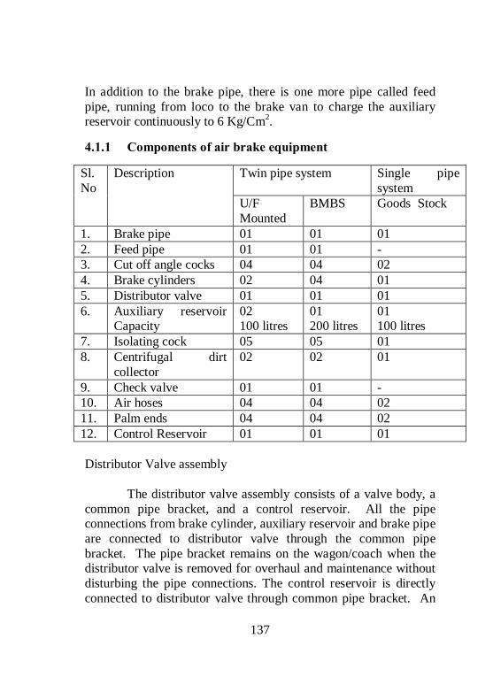
137
In addition to the brake pipe, there is one more pipe called feed pipe, running from loco to the brake van to charge the auxiliary reservoir continuously to 6 Kg/Cm2.
4.1.1 Components of air brake equipment
Twin pipe system Single pipe system
Sl. No
Description
U/F Mounted
BMBS Goods Stock
1. Brake pipe 01 01 01 2. Feed pipe 01 01 - 3. Cut off angle cocks 04 04 02 4. Brake cylinders 02 04 01 5. Distributor valve 01 01 01 6. Auxiliary reservoir
Capacity 02 100 litres
01 200 litres
01 100 litres
7. Isolating cock 05 05 01 8. Centrifugal dirt
collector 02 02 01
9. Check valve 01 01 - 10. Air hoses 04 04 02 11. Palm ends 04 04 02 12. Control Reservoir 01 01 01 Distributor Valve assembly The distributor valve assembly consists of a valve body, a common pipe bracket, and a control reservoir. All the pipe connections from brake cylinder, auxiliary reservoir and brake pipe are connected to distributor valve through the common pipe bracket. The pipe bracket remains on the wagon/coach when the distributor valve is removed for overhaul and maintenance without disturbing the pipe connections. The control reservoir is directly connected to distributor valve through common pipe bracket. An

138
isolating cock is provided either on the distributor valve or on the adaptor to isolate the distributor valve when found defective. A manual release valve is provided at the bottom of the distributor valve by which the brakes in a particular vehicle can be released manually by pulling the handle. Brake Cylinder The brake cylinder receives compressed air from auxiliary reservoir after being regulated by the distributor valve and converts to mechanical brake power by outward movement of its piston assembly. The compression spring provided in the brake cylinder brings back the rigging to its original position when brake is released. Different sizes of Brake Cylinders
Size of the cylinder Mounted on Stock
355 mm diameter / 14 inches Body Coaching & Goods Stock
304 mm diameter / 12 inches Body Brake Van 203 mm diameter / 08 inches Bogie Coaching Stock
Cut-off Angle Cock Cut off angle cocks are provided on either ends of the brake pipe and feed pipe. These cocks are used at the time of uncoupling of wagons/coaches. This has a vent feature. Once the cock is closed it allows the air trapped in the air hose to atmosphere. When MU washer or hose assembly itself has to be changed, the cut off angle cocks are closed which in turn isolates the brake/feed pipe from further charging and allows the entrapped air in the hose to flow out, to carryout the repairs safely. It also serves as dummy for the rear of the wagon/coach and the front of engine. When the handle is parallel to the pipe the cock, it is in

139
open position and when at right angles to the pipe, it is in closed position. Control Reservoir Control reservoir is mounted on the common pipe bracket. It always maintains a pressure of 5 Kg/Cm2 after charging. It works as a reference pressure to operate the different sub-assemblies/valves provided in the distributor valve to facilitate application and release of brakes. The brake pipe pressure acts in the top of the diaphragm and control reservoir pressure acting at the bottom of the diaphragm. Auxiliary Reservoir In air brake system, compressed air is required to be sent to the brake cylinder for brake application. If the compressed air is to be sent from the loco to brake cylinders of each coach, it will not be possible in the case of accident such as train parting. Hence it has become necessary to ensure sufficient quantity of compressed air with required pressure is always available in every rolling stock before the trains are despatched. That is why all the rolling stocks are provided with Auxiliary reservoirs to store the compressed air. Dirt Collector Dirt collectors are provided on branch pipes of both feed pipe and brake pipe. These are meant for removing dust, moisture and scale particles from air before it enters the distributor valve and auxiliary reservoir. This is achieved by centrifugal action. Check Valve with choke This is a one way valve / non-return valve which allows the compressed air from feed pipe to auxiliary reservoir and it

140
prevents the back flow of air from auxiliary reservoir to the feed pipe to avoid fall in auxiliary reservoir pressure in the event of failure of air supply from feed pipe. The choke provided in the check valve controls flow of air so that auxiliary reservoirs on the entire train can be filled uniformly. This is provided between the feed pipe and auxiliary reservoir. Isolation Cocks. There are five isolation cocks provided in the coaching stock. Locations of these cocks are given below. Location Nos. Remarks Between brake pipe and DV Between Distributors valve and brake cylinders. Between feed pipe and auxiliary reservoir. Between passenger emergency valve and brake pipe
01 02 01 01
(2 Cylinders)
Differences in Air brake systems of Coaching stock and Goods Stock Sl. No Description Coaching Stock Goods Stock
1 System Twin pipe Single pipe 2 Size of Brake pipe 25 mm 32 mm
3 Size of feed pipe 25 mm -
4 Number of brake cylinders
02 ( U/F Mounted ) 04 ( BMBS ) 01

141
5 Auxiliary reservoirs 02 (U/F Mounted) 01 ( BMBS )
01
6
Capacity of each AR
100 Ltr (U/F Mounted) 200 Ltr ( BMBS )
100 Ltr 75 Ltr (BVZC)
7. PEAS Available Not available
4.1.2 Twin pipe air brake system for passenger stock
Working principle of Air Brake Under normal conditions the Brake pipe is charged with 5 kg/Cm2 from the Loco. The control reservoir and the Auxiliary reservoir are also charged with 5 kg/Cm2 from BP through

142
Distributor valve in case of single pipe system. In twin pipe system the auxiliary reservoir is charged to 6 kg/Cm2 through feed pipe. When the brake pipe is 5 kg/Cm2, the brake cylinder is connected to exhaust through distributor valve in order to keep the brakes in released position fully. Whenever the brake pipe pressure is reduced below the CR pressure, the DV connects the auxiliary reservoir with the brake cylinder and the air from AR is sent into the brake cylinder to apply the brake. Whenever the brake pipe pressure is equal to CR pressure, the DV disconnects the BC from AR, and in turn connects the BC with Exhaust for the release of brakes fully.
Processes involved in working of Air brake system a. Charging b. Application c. Release. d. Manual Release Charging of Air brake system

143
Brake pipe is charged with 5 Kg/Cm2 by the drivers brake valve from the Loco. Feed pipe is charged with 6 Kg/Cm2. AR is charged with 6 Kg/Cm2. (Up to 5 Kg/ Cm2 it is charged by both brake pipe and feed pipe. Beyond 5 Kg/Cm2 & up to 6 Kg/Cm2 it is exclusively charged by feed pipe.) The CR is charged through the distributor valve to 5 Kg/sq cm from BP During charging Brake cylinder is connected to exhaust through distributor valve, to keep the brakes in released condition.
Application of brake in Air brake system For application the brake pipe is reduced in steps as given below.
Stages BP pressure is reduced by Minimum Reduction 0.5 to 0.8 Kg/Cm2. Service application 0.8 to 1 Kg/Cm2. Full service application 1 to 1.5 Kg/Cm2. Emergency application Above 1.5 Kg/Cm2.
When the brake pipe pressure is reduced in steps as shown above, the air from AR is sent into BC to a maximum pressure of 3.8 Kg/ Cm2, during full service application as well as emergency application.

144
During minimum reduction and service application the admission of air from AR in to BC is directly proportional to the reduction in the BP pressure. Note: Before AR is connected to BC, the AR and CR are disconnected from BP, and BC also is disconnected from Exhaust. The AR is continuously charged to 6 Kg/Cm2 during brake application by Feed pipe. The CR pressure should remain at 5 Kg/Cm2. However there may be a little drop in CR pressure during brake application, due to the design.
Releasing/Recharging of Air brake system During release, the BP pressure is increased in steps. When the BP pressure is increased in steps, the brake cylinder is disconnected from AR and in turn connected to exhaust. The air from Brake cylinder is released / vented progressively depending upon the increase in the brake pipe pressure. When the brake pipe pressure is brought to 5 Kg/Cm2 the air from brake cylinder is completely exhausted and the brakes are released fully.

145
Manual Releasing Whenever the loco is detached, BP pressure is brought to zero and brake application takes place due to the existence of CR pressure at the bottom of the main diaphragm. To release the brakes manually, the hollow stem in the DV should be brought to the normal position by releasing the air from CR. To facilitate this, the release valve provided at the bottom of the DV is given a brief pull. During this operation, the air from CR is released which in turn brings the hollow stem to the normal position to connect BC with exhaust for releasing of brakes. Requirement of choke for charging of Auxiliary reservoirs; With 100 lts capacity AR on each wagon, for a formation of 59+1 wagons approximately 6000 litres of air is required for charging the auxiliary reservoirs. Main reservoir capacity of loco is only 750 litres, if the auxiliary reservoirs are charged directly without any restrictions; the main reservoir pressure will drop abruptly, which is not safe. In order to prevent the MR pressure from dropping abruptly, the air brake system is designed to use only the air delivered by the compressor (free air delivery) to charge the AR and to maintain

146
MR pressure within prescribed limits. Hence auxiliary reservoirs are charged through restricted passage (choke).
Ensuring complete charging of the system; While charging the formation, Brake pipe is charged first before Auxiliary reservoirs. The volume of air required for charging the brake pipe for one wagon is only 10 litres. So a formation which consists of 58+1 wagons requires approximately 600 litres of air for charging the brake pipe when compared to 6000 litres in the case of auxiliary reservoirs. As the free air delivery of compressed air from the loco is about 1500 to 2000 litres per minute at normal speed, moreover only 600 litres of air only required for the brake pipe, it is charged to the required pressure within a minute (60 Seconds).

147
Even though gauge fitted with brake and the feed pipe in the brake van records a minimum of 4.8 Kg/Cm2 and 5.8 Kg/Cm2 respectively within a minute, AR and CR are yet to be charged to the required pressure, for which it takes about 180 to 240 seconds. Hence to ensure full charging of the system at least 4 minutes to be allowed, then only brake application will be effective.
4.1.2.1 REQUIREMENT OF TWIN PIPE SYSTEM IN COACHING STOCK
Charging time of Auxiliary reservoirs As the free delivery of compressed air from the loco is 1500 litres to 2000 litres per minute at normal speed, to charge 6000 litres of air in the auxiliary reservoirs, it takes about 180 to 240 seconds. To charge AR by 5 Kg/Cm2 = 240 Seconds (Maximum) To charge AR by 1 Kg/Cm2 = 48 Seconds (Maximum) Application time The application time is the time taken by the Distributor valve to admit a pressure of 3.6 Kg/Cm2 in to Brake cylinder from

148
the Auxiliary reservoir during Full service application or Emergency application. The application time for the coaching stock is 3 to 5 Seconds. The application time for the Goods stock is 18 to 30 seconds. After the Full service or Emergency brake application the brake cylinder gets a maximum pressure of 3.8 Kg/Cm2 from Auxiliary reservoir. Releasing time The releasing time is the time taken by the Distributor valve to release the air from Brake cylinder from 3.8 Kg/Cm2 to 0.4 Kg/Cm2. Note: The releasing time does not depend upon the piston displacement but it depends upon the BC pressure only. The releasing time for the coaching stock is 15 to 20 Seconds. The releasing time for the Goods stock is 45 to 60 seconds. The difference in the application time and release time between the coaching and goods stock DVs is achieved by varying size of the choke in DV between the AR and BC for the application, and by varying size of the choke in DV between Brake cylinder and Exhaust for the release. Hence the DVs of coaching & freight stocks are not interchangeable, since the application and release timings are different for coaching and freight stock. During brake application, as the air from Auxiliary reservoir is sent in to brake cylinder, there is always a reduction in the AR pressure and it is likely to drop to 4.2 Kg/Cm2. hence during release, it must be ensured that before the air from brake cylinder is released completely, the AR should be recharged to 5 Kg/Cm2, so that the system can be kept ready for next brake application.

149
To charge AR from 4.2 to 5 Kg/Cm2 the DV takes approximately 36 Seconds, and to release the air from BC from a pressure of 3.8 Kg/Cm2 to O.4 Kg/Cm2 the DV takes 45 to 60 Seconds in the case of goods stock.
From the above facts, as it is possible to recharge the AR from 4.2 to 5 Kg/Cm2 within the release time of 45 to 60 seconds, a Single pipe system itself is sufficient for the Goods stock. In the case of coaching stock, to release the air from BC from the pressure of 3.8 Kg/Cm2 to 0.4 Kg/Cm2 the DV takes 15 to 20 Seconds. And to re-charge AR from 4.2 to 5 Kg/Cm2 after application, DV takes approximately 36 Seconds

150
From the above fact, it is clear that it is not possible through DV to recharge the AR from 4.2 to 5 Kg/Cm2 within the releasing time of 15 to 20 seconds for the Coaching stock.
Hence it has become necessary to introduce one more pipe called feed pipe to recharge the AR always to 6 Kg/Cm2, from the other end of the AR within the release time of 15 to 20 seconds and there by auxiliary reservoir pressure is maintained to optimum level for repeated brake applications.

151
4.1.3 Passenger emergency alarm system
Passenger emergency alarm system is provided between the main brake pipe and the alarm chain. When the alarm chain is pulled, the air pressure from the Brake pipe is vented out through the 8 mm choke provided in the Passenger emergency alarm valve. Due to the sudden drop of air pressure from the brake pipe in the system, the airflow indicator in the Locomotive deflects from its normal position and also gives hooting signal. By this the driver comes to know about the drop in BP in the formation and he applies the brakes to stop the train. The passenger emergency alarm system consists of two main parts. 1. Passenger emergency alarm valve (PEAV) 2. Passenger emergency alarm signal device (PEASD) The passenger emergency alarm valve (PEAV) consists of a spring loaded hollow piston fitted with a check valve at the bottom. It has also got a control chamber at the bottom of the piston and a brake pipe chamber at the top of the piston. An 8 mm diameter exhaust port is provided at the bottom of the valve to release the air from main brake pipe. The brake pipe chamber available at the top of the piston is connected with the PEASD through branch pipes. The PEASD consists of a pilot valve which can be operated by pulling the chain by the passenger. It is also provided with two numbers of exhaust ports to facilitate the removal of air from the top of the piston (Brake pipe chamber) by pulling the chain. WORKING During charging the brake pipe chamber and the control chamber of PEAV is charged with 5 Kg/Cm2, the control chamber is charged through the restricted passage. The air which is available at the brake pipe chamber at the top of the piston is also made

152
available at the top of the pilot valve of PEASD. During charging the spring loaded check valve closes the passage between main brake pipe and the exhaust of PEAV. (Ref. fig)
When the chain is pulled by the passenger, the pilot valve in PEASD is lifted first. The air from brake pipe chamber of PEAV is then released through the exhaust ports of PEASD and in turn brings the pressure at the top of the piston to zero immediately. Due to the existence of control pressure at the bottom of the piston, the hollow piston gets lifted, which in turn connects the main brake pipe with the exhaust to deplete the air from main brake pipe to initiate brake application. Resetting of PEASD Unlike vacuum brake, where in turning the disc will automatically reset the valve, in air brake system in addition to the turning the disc, the key which is integral part of PEASD has to be turned by 90 degree clockwise. In recent modification a wire rope is connected to the PEASD so that it can be reset from ground level eliminating the need to climb the coach for resetting the PEASD.

153
4.1.4 Trouble shooting faults in air brake system en-route;
The major problems noticed in the air brake system are BP punctured / Hose burst, FP punctured / Hose burst, AR pipeline punctured or damaged, Malfunctioning of DV, Malfunctioning of PEAS. BP punctured / Hose burst In case of single pipe system, if brake pipe is punctured the brakes get applied on the full formation. The affected wagon should be detached from the formation. In case of twin pipe system, if the brake pipe is punctured, the brake pipe of the affected coach can be by passed without detaching the coach by connecting the FP of the affected coach with the BP of the adjacent coach. A specially made intermediate coupling made by welding the FP and BP palm ends together is available to establish these connections. FP punctured / Hose burst The train has to be run with single pipe system isolating the FP pipe from the first coach itself. AR pipeline punctured or damaged If the branch pipe between the FP and AR is punctured, the Isolating cock provided on the branch pipe of FP of the particular coach can be isolated and that particular coach will work on single pipe system. If the branch pipe between the common pipe bracket and AR is punctured, both the isolating cocks on the BP and FP branch and also the DV to be isolated and the particular coach will not have brake power, this has to be endorsed on the BPC. Malfunctioning of DV. DV to be isolated and ensure the brakes are released. It has to be endorsed in BPC.

154
Malfunctioning of PEAS. In the case of leakage through PEAV, if the leakage is not arrested even after resetting the PEASD, isolate the cock provided between the BP pipe and the PEAV.
4.1.5 Single car testing for Air Brake Rolling Stock.
The different tests conducted with a Single car test rig; 1. Leakage in Feed pipe. 2. Leakage in Brake pipe. 3. Brake cylinder filling time. 4. Brake cylinder releasing time. 5. Sensitivity test. 6. Insensitivity test. 7. Emergency application test. 8. Piston Stroke. 9. Leakage in the Brake cylinder. 10. Graduated Application test. 11. Graduated release test. 12. Working of PEAS. 13. Working of GEV. 14. Manual release Test. Procedure for conducting of Single Car Test Rig

155
1 LEAKAGE IN FP AND BP. a. Charge the system fully. b. Close the Cock No. 1 and 3. c. Observe the pressure drop in FP and BP for three minutes. The leakage rate in the FP and BP should not be more than
0.2 Kg/Cm2 in one minute in FP 0.2 Kg/Cm2 in one minute in BP for coaches 0.1 Kg/Cm2 in one minute in BP for wagons
2. BC FILLING TIME. a. Charge the system fully b. Bring the A-9 valve to full service application position. c. Observe the BC pressure. d. The BC pressure should reach to 3.6 Kg/Cm2 within
3 to 5 seconds for Coaching stock 18 to 30 seconds for Goods stock.

156
e. Observe the maximum pressure. It should be 3.8 Kg/Cm2. 3. BC RELEASING TIME. a. Bring the A-9 valve to release position. b. Observe the BC pressure. c. The BC should drop from 3.8 Kg/Cm2 to 0.4 Kg/Cm2 within
15 to 20 seconds for Coaching stock 45 to 60 seconds for Goods stock.
4. SENSITIVITY TEST. a. Open the cock No.7 and Charge the system fully. b. Close the Cock No.2 and Open the cock No.4. c. Wait for 6 seconds and close the cock No.4. (This will reduce the BP pressure by 0.6 Kg/Cm2 in 6 sec automatically) d. Observe the Brake cylinder. The brake should be in applied condition. 5. INSENSITIVITY TEST. a. Open the cock No.7 and Charge the system fully. b. Close the cock No.2 and Open the cock No.5. c. Wait for 60 seconds and close the cock No.5. (This will reduce the BP pressure 0.3 Kg/Cm2 in 60 seconds automatically) d. Observe the Brake cylinder. The brake should not be in applied condition. e. Observe the BP and CR pressure. Both should be at 4.7 Kg/Cm2 6. EMERGENCY APPLICATION TEST. a. Close the cock No.7 and Charge the system fully. b. Close the cock No.2 and Open the cock No.6.

157
c. Observe the Brake cylinder pressure. The maximum BC should be 3.8Kg/ Cm2. 7. PISTON STROKE After the emergency or full service application measure the piston stroke. It should be within
65 ± 10 mm for coaching stock (UF mounted)
85 ± 10 mm for goods stock –Empty 130 ± 10 mm for goods stock - load 25 to 32 mm for BMBC 87±10 mm for BTPN 70 ±10 mm for BVZC 120±10 mm for BOBRN
8. LEAKAGE IN BC. a. After the emergency brake application observe the leakage in the Brake cylinder. b. The leakage in the BC should not be more than 0.1 KG/Cm2 in 5 minutes. 9. GRADUATED APPLICATION TEST. a. Charge the system fully. b. Reduce the BP pressure in steps through A-9 valve. c. Observe the BC pressure. The pressure should increase in steps
BP BC 5.0 0 4.5 1.25 4.2 2.0 4.0 2.5 3.8 3.0 3.5 3.8

158
10. GRADUATED RELEASE TEST. a. Increase the BP pressure in steps through A -9 valve. b. Observe the BC pressure. The pressure should decrease in steps.
BP BC 3.5 3.8 3.8 3.0 4.0 2.5 4.2 2.0 4.5 1.25 5.0 0
11.WORKING OF PEAS. a. Charge the system fully. b. Pull the alarm chain from inside the coach. c. Observe the BP pressure and BC. d. BP pressure should drop and brake should apply. e. Reset the PEASD. f. Observe the BP pressure and BC. g. BP pressure should reach to 5 KG/Cm2 and brake also should release. 12.WORKING OF GEV (Guard Emergency Valve); a. Charge the system fully. b. Operate the GEV handle. c. Observe the BP pressure and BC. d. BP pressure should drop and brake should apply. e. Bring back the GEV to normal position. f. Observe the BP pressure and BC.

159
g. BP pressure should reach to 5 KG/Cm2 and brake also should release. MANUAL RELEASE TEST. a. Disconnect the test rig from the rolling stock. b. Pull the release valve handle. c. Observe the CR pressure and BC. d. The CR pressure should drop to 0 KG/Cm2 and Brake should release without any jerks.
4.1.5.1 PROFORMA FOR SINGLE CAR TEST (ICF COACH)
Coach No. Type Of DV and SL.No: BP Pressure: FP Pressure: Sl. No.
Check Specified Actual
1. Leakage rate a) Brake pipe 0.2 Kg/cm2 per minute
(max.)
b) Feed pipe 0.2 Kg/cm2 per minute (max.)
2. a) Brake cylinder filling time (from 0 to 3.6 kg/cm2)
3 to 5 seconds
b) Maximum Brake cylinder pressure
3.8 + 0.1 Kg/cm2
3. Brake cylinder release time (3.8 to 0.4 Kg/cm2)
15 to 20 seconds
4. Sensitivity & Insensitivity

160
a) Brake application when brake pressure is reduced at the rate of 0.6 Kg/cm2 in 6 seconds
Brake should apply
b) Brake application when brake pressure is reduced at the rate of 0.3 Kg/cm2 in 60 seconds
Brake should not apply
5. Emergency brake application and release
a) Maximum brake cylinder pressure
3.8 + 0.1Kg/cm2
b) Manual release of brake cylinder after emergency application
Brake cylinder should get fully released
6. Graduated application and release
a) Application Brake pipe pressure decreases in steps and Brake cylinder pressure builds up in steps
b) Leakage in Brake cylinder pressure in 5 minutes after emergency application
0.1 Kg/cm2 within 5 minutes
c) Release Brake pipe pressure increases in steps and Brake cylinder pressure reduces in steps
7. Piston stroke 25-32 mm

161
Sl. No.
Check Specified Actual
8. Passenger alarm system
a) Pull handle (1) Air to exhaust from PEAV. (2) Brake should apply (3) Coach indication light should glow
b) Reset PEASD Exhaust of air should stop and indication light should extinguish
9. Guard’s emergency valve test
a) Pull valve handle Brake pipe air to exhaust. (2) Brake should apply
b) Normalize the handle
Air exhaust to stop
c) Testing of Brake pipe and Feed pipe in guard’s compartment
Gauges should register variation in Brake pipe and Feed pipe.
10. Dirt collector Cleaned / Renewed
4.2 BOGIE MOUNTED BRAKE SYSTEM
In order to overcome the problems faced due to the breakages and malfunctioning of SAB en-route, and also due to the frequent breakages and replacement of Cast Iron brake blocks, Bogie Mounted Brake System is introduced. In this system, the brake rigging in the under frame and SAB’s are eliminated by mounting the cylinders directly on the bogie frame itself.

162
Since the brake force available is less, High friction ‘K’ type composite brake block is used to overcome the deficiency in brake power.
4.2.1 Special features of Bogie Mounted Brake System
External slack adjusters are eliminated. High friction composite “K” type brake blocks are used, whose life is increased by 5 to 6 times than that of cast iron brake blocks. It has an in-built slack adjuster by which the effective length of the piston rod can be increased by 305mm automatically; whenever the piston stroke exceeds 32mm due to wear on the brake blocks and the wheel. Totally 4 Nos. of 8” size brake cylinders (2 per bogie) are used in place of two Nos. of 14” cylinders in standard body mounted air brake system. The cylinders are mounted between central longitudinal members connecting the bogie transom and the head-stock on either side. Unusual noise emitted by the anti-vibration bracket in case of SAB, on run is completely eliminated. It is provided with less No. of brake fittings, therefore easy to maintain. The forces acting on the levers and truss beams is only 40% when compared to under frame mounted system, therefore the wear on the brake gear components are less, and hence the frequent replacements of these components are minimised. As the forces acting on the Truss beam is only 1 tonne, when compared to 3.2 tonnes in the under frame stock, 13 tonnes capacity truss beams are sufficient. Bogie Mounted Brake Cylinders The Bogie Mounted Brake Cylinders are provided with an in-built slack adjuster to maintain a constant brake block clearance automatically. It is a single acting slack adjuster by which the

163
clearance between wheel and brake block can be decreased automatically by increasing the effective length of piston rod whenever the piston stroke exceeds 32mm due to wear on the brake block and the wheel. The adjustment takes place during return stroke.
If the clearance between wheel and the brake blocks is less due to any reason, it does not bring the required clearance automatically. Main parts of Bogie Mounted Brake Cylinder The main parts of the Bogie Mounted Brake Cylinders are:
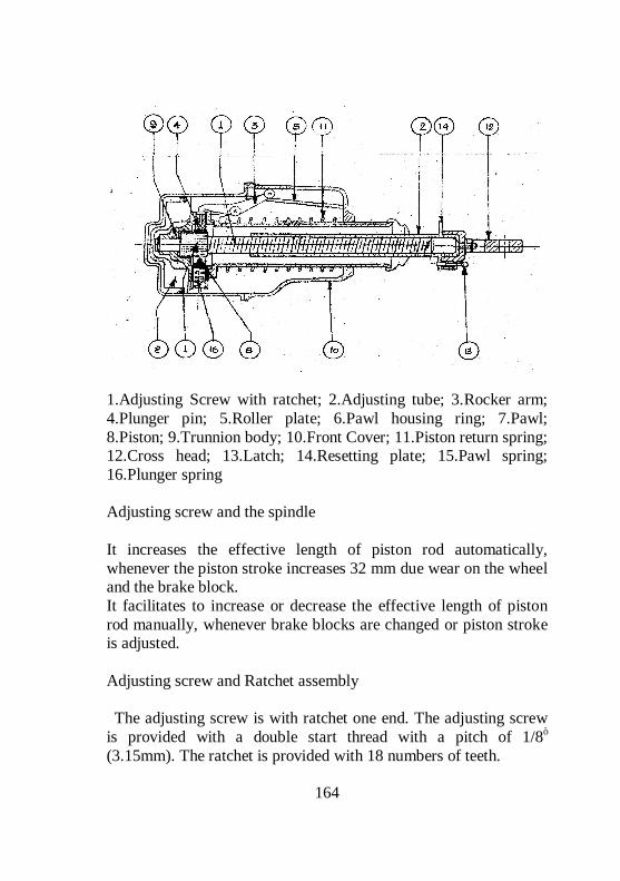
164
1.Adjusting Screw with ratchet; 2.Adjusting tube; 3.Rocker arm; 4.Plunger pin; 5.Roller plate; 6.Pawl housing ring; 7.Pawl; 8.Piston; 9.Trunnion body; 10.Front Cover; 11.Piston return spring; 12.Cross head; 13.Latch; 14.Resetting plate; 15.Pawl spring; 16.Plunger spring Adjusting screw and the spindle It increases the effective length of piston rod automatically, whenever the piston stroke increases 32 mm due wear on the wheel and the brake block. It facilitates to increase or decrease the effective length of piston rod manually, whenever brake blocks are changed or piston stroke is adjusted. Adjusting screw and Ratchet assembly The adjusting screw is with ratchet one end. The adjusting screw is provided with a double start thread with a pitch of 1/8”
(3.15mm). The ratchet is provided with 18 numbers of teeth.

165
When the adjusting screw completes one full rotation, it makes the adjusting tube to move forward by 2x1/8” = ¼” (6.33mm) If the ratchet is moved/turned by one tooth, the adjusting screw is turned by 3600 ÷ 18 = 200, which inturn moves the adjusting tube outward by ¼ x 1/18 = 1/72” (0.33mm). From the above, it is clear that, to move the adjusting tube forwards automatically by ¼” it requires 18 return strokes. Rocker Arm The Rocker Arm is fitted with piston head by means of shackles and it moves along with the piston head.
The roller end of the rocker arm slides over the roller plate, and on the other end of rocker arm rests on the pawl housing through the plunger pin. The function of rocker arm is to press the pawl housing ring downward during return stroke and it allows/permits the pawl housing ring to move upwards during forward stroke. Roller Plate The Roller plate is fixed at an angle with the front cover by means of bolts. The function of Roller plate is to displace the pawl

166
housing vertically when the rocker arm moves horizontally. (OR) it converts the linear displacement of rocker arm into vertical displacement of pawl housing.
The rocker arm should be kept horizontal position facing to the gauge face of the wheel in BMBS due to the following reason; When the brake is applied the piston rod which is connected to the floating lever moves in a circular path with respect to lever’s fulcrum point. This horizontal position of rocker arm facilitates the piston to move linearly outward as well as vertical downward along with the floating lever during brake application. If the vertical displacement of the piston is prevented by keeping rocker arm facing upwards will result in brake binding due to the jamming of piston with the cylinder. Pawl Housing Ring / Pawl The pawl-housing ring is pivoted with pivot pin of trunnion body at one end and the other end of the pawl housing ring moves/turn freely.

167
A spring-loaded pawl is housed at the free end of the pawl housing. At the bottom of the pawl housing a spring loaded plunger/sleeve is kept between trunnion body and the pawl housing to move the pawl housing upwards/outwards during forwards stroke. At the top, a plunger pin is kept between the rocker arm and the pawl-housing ring to move the pawl ring downward/inward during return stroke. The function of pawl housing and the pawl is to turn the ratchet by one tooth whenever the piston stroke exceeds 32mm to increase the effective length of piston rod during return stroke automatically. Working of in-built slack adjuster

168
When the piston stroke is within 32mm, the spring-loaded pawl in the pawl housing moves between the two teeth of the ratchet and keeps the effective length of piston rod unaltered.
When the piston stroke exceeds 32mm during the forward stroke due to the wear on the brake block and the wheel, the pawl slips and takes the position of next tooth in the ratchet. During the return stroke, the rocker arm pushes the plunger pin inwards/downwards which inturn turns the pawl-housing ring clockwise. The pawl which is housed in the pawl housing turns the ratchet with the adjusting screw by 200 causing the adjusting tube

169
to move forward by 1/72” to increase the effective length of the piston rod. Parts of Brake Rigging: Lever- Straight, Lever – Z shaped, Lever Hanger, Connecting Link.

170
The schematic diagram of Brake rigging of BMBS is given below.
Precautions to be followed while maintaining the Bogie Mounted Brake System Ensure the bogies are provided with the high friction composite “K” type brake blocks. Co-efficient of Composite K- type brake block is 0.28 - 0.3 Ensure that the floating levers are not interchanged between AC and Non AC coaches.

171
Ensure the levers are not reversed. Ensure the connecting links (pull rod) are not interchanged between AC and Non-AC coaches.
Ensure the connecting link (pull rod) is not reversed. Whenever the wheel diameter is reduced to 839mm, ensure the brake gear connection is shifted to next inner hole of pull rod.

172
Ensure 38mm packing is given between dashpot and the axle box wing whenever the wheel diameter is reduced to 839mm. Whenever the red mark is seen on the adjusting tube, replace all the brake blocks since further take up of clearance is not possible.
Ensure correct size of brake gear pins and bushes are used in brake rigging. Ensure the piston stroke is within 32mm. If more, the in-built slack adjuster is defective and the replace the brake cylinder. Ensure the rocker arm end is kept horizontal and facing towards the gauge face of the wheel. Difference between Under frame Mounted & Bogie Mounted brake system
Sl. No Description U/F Mounted
brake System Bogie Mounted brake System
1 Slack Adjuster External Internal
2. Type of Slack adjuster Double Acting Single Acting
3. Capacity of Slack adjuster 450 mm 305 mm
4. Size brake cylinder 14 Inches 08 Inches
5. Number of Cylinders 02/Coach 04/Coach

173
6. Brake Force available on the Brake head
3 Tonne (Non mod) 2.2 Tonne (Modified)
1 Tonne
7. Type of Brake block
Low friction Composite L-Type brake block
High friction Composite K- Type Brake block
8. Co-efficient of brake block 0.16 – 0.18 0.28 – 0.30
9. Thickness of brake block 60 mm 50 mm
10. Piston Stroke
80–100 mm (Non mod) 60-70 mm (Mod H/L)
Working Stroke-32 mm
11. Capacity of Truss beam 16 Tonnes 13 Tonnes
12. Weight of brake block 3.06 Kgs 2.5 Kgs
13 Anti vibration Bkt Required Eliminated
14 Horizontal lever Required Eliminated
15. Bogie pull rod Required Eliminated
16 Life of the brake gear Components including wheel
Less More
17. Number brake gear adjustments 07 02
Procedure for replacing the Brake Blocks & adjusting the piston stroke:

174
Disengage the cross head from the adjusting tube, by pulling the latch. Turn the adjusting tube clockwise to decrease the length of adjusting tube (effective) length of piston rod. After replacing the brake blocks, apply the brake and check the piston strokes. If piston stroke is correct, engage the cross head with the resetting plate by releasing the latch. If the piston stroke is more, increase the length of adjusting tube, to decrease the clearance between wheel and brake block. If piston stroke is less, decrease the length of adjusting tube, to increase the clearance between wheel and brake block. After adjusting the piston stroke, ensure the cross head is locked with adjusting tube with the latch. Maximum Stroke: This is the stroke beyond which the piston cannot come outward. It is 95mm for coaching stock. Working stroke: This is the stroke at which, the in-built slack adjuster increases the effective length of the piston rod automatically whenever the clearance increases due to wear on the brake block and the wheel. It is 32mm for coaching stock. The angle at which the roller plate is kept with horizontal position determines the working stroke. The roller plate should be kept at an angle of 10.50 with horizontal to have a working stroke of 32 mm for coaching stock. Number of return strokes required to increase the effective length of piston rod automatically in BMBS 72 return strokes required for 1” 36 return strokes required for ½” 18 return strokes required for ¼”

175
4.2.1.1 REQUIREMENT OF IN BUILT SINGLE ACTING SLACK ADJUSTER IN BMBC;
The bogie mounted brake cylinders are designed to maintain a clearance of 6 to 8 mm between the wheel and brake block when the piston stroke is 25 to 32 mm. Generally the manual brake adjustment is done whenever the wheel diameter reduces and not if the thickness of brake block reduces. hence when a new brake block is fitted, before it could reach to condemning size it has to wear more than 35 mm, which in turn increases the clearance between the wheel and brake block gradually from 6 mm/8mm to 41/43mm. Piston stroke of up to 250 mm is required to have brake application in such case and it is not possible as the maximum piston stroke in BMBS is limited to 95 mm. hence inbuilt slack adjuster has become necessary to maintain a constant clearance between the wheel and brake block. The inbuilt slack adjuster increases the effective length of piston rod automatically in order to maintain a constant clearance, whenever the piston stroke exceeds 32mm due to increased clearance on account of wear on the brake block and the wheel. The maximum pay out capacity of the piston rod is 305 mm.
4.3 DISTRIBUTOR VALVES
Functions of Distributor valves: It connects AR with BC during Brake application. It connects BC with Exhaust during brake release. It charges AR to 5 Kg/Cm2 from BP during charging. It disconnects the AR from BP during brake application. It charges the CR to 5 Kg/Cm2 from BP during charging. It disconnects the CR from BP during brake application. It admits a maximum pressure of 3.8 Kg/Cm2 during emergency as well as full service application. It admits the air from AR into BC in steps gradually, in proportion to the reduction in the Brake pipe pressure to facilitate graduated brake application. It releases the air

176
from BC in steps gradually, in proportion to the increase in the brake pipe pressure to facilitate graduated brake release. It reduces the BP pressure further by 0.4 Kg/Cm2 in addition to the brake pipe pressure reduced by the driver from the loco to accelerate the brake application particularly during minimum reduction. It admits air from AR into BC to a pressure of 0.8 Kg/Cm2 immediately during brake application to overcome the resistance offered by the brake rigging. It applies the brake during sensitivity range, when the brake pipe pressure is reduced at the rate of 0.6 Kg/Cm2 in 6 seconds. It does not apply the brake during insensitivity range when the brake pipe pressure is reduced at the rate of 0.3 Kg/Cm2
in 60 seconds. It releases the air from CR, AR and BC during manual release. It isolates the brake system of the Rolling Stock when ever necessary. Different types of distributor Valve, Their Manufacturers and present status
Sl. No Type Manufacturers Present
status M/s. Geysham and Co, Delhi. Supplying. M/s. Faiveley Transport India Ltd, Hosur. Supplying.
M/s. Stone India Ltd, Kolkota. Supplying. 01. C3W
M/s. Bharath Brakes & Valves, Kolkota
Not Supplying.
M/s. Escorts, Faridabad. Supplying. 02. KEO
(EK) M/s. Knorr-Bremse India Ltd, Faridabad, Supplying.
M/s. S.D.Technical Services Pvt Ltd, Delhi.
Not Supplying. 03. P4aG M/s. Westing house,
Saxby,Farmer,Ltd, Kolkota Not Supplying.

177
Mainly two types of DVs are used in Indian Railways EK type Distributor Valve & C3W Distributor Valve
4.3.1 EK Type Distributor Valve
The different sub-assemblies of EK type distributor valve Three pressure valve, A-Controller, U-Controller , R-Charger, Minimum pressure limiter, Maximum pressure limiter, Quick release valve, Isolating valve.
Three-pressure valve; Three pressures, ie BP, CR & BC pressure acts on this valve, It connects AR with BC during brake application. It connects BC with Exhaust during brake release. It admits BC pressure in steps, when the brake pipe pressure is reduced in steps, to facilitate graduated application. It releases air from BC in steps, when the

178
brake pipe is pressure is increased in steps, to facilitate graduated release. ‘LAP POSITION’ of distributor valve This is the position of the Hollow stem of the Main Valve / Three pressure valve, in which the Brake cylinder is connected neither to AR nor to exhaust, during brake application / Release for the purpose of facilitating Graduated brake application / Release. The hollow stem is designed to take LAP POSITION up to full service application in case of EK DV and even after Emergency application in case of C3W. The Hollow stem takes LAP POSITION as soon as Brake cylinder gets sufficient pressure in proportion to the reduction in the BP pressure to facilitate graduated brake application and release, for this purpose in addition to the Main diaphragm one more diaphragm called BC diaphragm is connected with the hollow Stem.

179
During brake application, initially the hollow stem gets lifted, due to the difference of forces offered across the main diaphragm. The lifting hollow stem allows the air from AR into BC. As soon as BC gets sufficient pressure, which will offer a down ward force on the BC diaphragm equivalent to the upward force offered by the main diaphragm. Once the down ward force offered by the BC pressure on the BC diaphragm, equals the upward force offered by the main diaphragm, the hollow stem which is lifted initially, comes down to take LAP POSITION as shown in the figure. U-Controller; The function of U-Controller is to reduce the Brake pipe pressure further by 0.4 Kg/Cm2, in addition to the brake pipe pressure reduced by the driver from the Loco, to accelerate the brake application. Working: During brake application, particularly during minimum reduction, as soon as three pressure valve is lifted from its normal position, the BP chamber of three pressure valve is connected to exhaust through the U-Controller. The air from BP chamber of three pressure valve is exhausted immediately. This exhaust of BP pressure causes quicker reduction in BP pressure, which in turn helps to lift the three pressure valve quickly, to facilitate quicker application of brakes during minimum reduction As soon as BC gets a pressure of 0.4 Kg/Cm2, the U-Controller closes the passage between BP and exhaust, which in turn prevents any further drop in BP pressure. A-Controller: It charges Control reservoir to 5 Kg/Cm2 from BP during charging. It isolates the CR from BP, when the brake pipe pressure is reduced

180
at the faster rate, during sensitivity range. It connects CR with BP, when the brake pipe pressure is reduced at the slower rate, during insensitivity range. Note: This valve is normally kept in open position and synchronised with BC pressure. As soon as BC gets a pressure of 0.2 Kg/Cm2 A-controller closes the passage between CR and BP during the brake application. The additional check valve provided at the bottom of the A-Controller closes the passage between CR and BP temporarily to prevent any loss in the CR pressure with the help of BP pressure, before it is permanently closed by the BC pressure. Insensitivity range It is likely that some leakage will crop up further in the train en-route, after the attention and dispatch. These small leakages should not lead to brake application, which can lead to detention to the trains. Hence a pressure drop of 0.3 Kg/Cm2 in 60 seconds is kept as insensitivity range for the DV not to actuate the brake application. Where as the pressure drop during sensitivity range is 0.6 Kg/Cm2 in 6 seconds. From the above it is very clear that the pressure drop during insensitivity range is 1/20th of pressure drop during sensitivity range. As the pressure drop is very less, the upward force offered by this pressure drop across main diaphragm also is less. This less force (1 Kg approximately at every second) is not at all sufficient to lift the hollow stem of the three-pressure valve. As the hollow stem is not lifted, AR is not connected to BC. We also know that there is a passage between CR and BP through A- Controller and this passage is closed as soon as BC gets a pressure of 0.2 Kg/Cm2 during brake application. Since the BC is not at all getting any air from AR, the passage between CR and BP remains in open condition and in turn allows the CR pressure also to release along with the brake pipe pressure at the rate of 0.3 Kg/Cm2 in 60 seconds.

181
As there is no pressure difference across main diaphragm at every point of time, the hollow stem is not lifted and thus brakes are also not applied during insensitivity range.
R-charger: R- Charger charges the auxiliary reservoir by allowing air from B.P. up to 5 kg/Cm2 in both single and twin pipe system during charging. It prevents back flow of air from AR to BP during brake application. Minimum and Maximum pressure limiters: The function of Minimum pressure limiter is to admit a pressure of 0.8 Kg/Cm2 immediately in to the brake cylinder during

182
brake application to overcome the resistance offered by the brake rigging. The function of Maximum pressure limiter is to admit and limit to maximum pressure of 3.8 Kg/Cm2 into brake cylinder even after emergency application. Working: Initially during brake application the air from AR is sent in to BC through two passages. One with restrictions and another without restrictions. As soon as BC gets a pressure of 0.8 Kg/Cm2 the minimum pressure limiter closes the non-restricted passage and further admission of air from AR to BC is through restricted passage. When the BC gets a pressure of 3.8 Kg/Cm2 the Maximum pressure limiter closes the non-restricted passage also. As both the passages are closed, the AR is completely disconnected from BC, and further admission of air from AR in to Brake cylinder is stopped. Quick release valve: Quick release valve releases air from CR manually to facilitate manual release. The AR pressure can not be released by just pulling Quick release valve in case of EK make DV. For releasing AR pressure, DV handle has to be isolated. Isolating valve: The functions of isolating valve are to isolate the DV in case of malfunctioning, release the air from AR manually, release the air from BC manually. Working: When the handle is in vertical (working) position the brake pipe is connected with DV. When the handle is in horizontal position, the Brake pipe is disconnected from DV. The AR and BC are connected to exhaust through the exhaust port provided in the isolating valve.

183
Note: Initially brake application will take place and after sometime the brake will release automatically, since BC is connected to Exhaust. The sketch of EK type distributor valve with different sub- assemblies is given in the following pages. Path of air during charging, graduated and emergency application is shown in each page.

184

185

186

187
4.3.2 C3W distributor valve
Different sub-assemblies of C3W type distributor valve are; Main valve, Cut off valve, Quick service valve, In shot valve, AR check valve, Double release valve, Isolating valve. Main valve: The functions of Main valve are; It connects AR with BC during brake application. It connects BC with Exhaust during brake release. It admits BC pressure in steps, when the brake pipe pressure is reduced in steps, to facilitate graduated application. It releases air from BC in steps, when the brake pipe is pressure is increased in steps, to facilitate graduated release. It also acts as a maximum pressure limiter, to admit a maximum pressure of 3.8 kg/Cm2 into BC during emergency brake application. Main valve is provided with two concentric pistons. One is larger and another one is smaller in area. During emergency brake application, leaving the larger piston in lifted position, the smaller piston along with hollow stem comes down to take LAP position as soon as BC gets maximum pressure of 3.8 kg/Cm2. Cut off valve: It charges Control reservoir to 5 Kg/Cm2 from BP during charging. It isolates the CR from BP, when the brake pipe pressure is reduced at the faster rate, during sensitivity range. It connects CR with BP, when the brake pipe pressure is reduced at the slower rate, during insensitivity range. It also charges AR to 5 kg/Cm2 during charging. Note: This valve is normally kept in open position and synchronised with BC pressure. As soon as BC gets a pressure of

188
0.2 Kg/Cm2Cut off valve closes the passage between CR and BP during the brake application, which inturn prevents any further drop in CR pressure. AR- Check valve: The functions of AR- Check valve are,; To charge the auxiliary reservoir from B.P. to 5 kg/Cm2 in single pipe system during charging through cut off valve. It prevents back flow of air from AR to BP during brake application. Quick service valve: The function of Quick service valve is to reduce the Brake pipe pressure further by 0.4 Kg/Cm2, in addition to the brake pipe pressure reduced by the driver from the Loco, to accelerate the brake application. Working: During brake application, particularly during minimum reduction, as soon as the brake pipe pressure is reduced, the BP chamber of Main valve is connected to Quick service bulb through the Quick service valve. The air from BP chamber of Main valve is allowed to expand suddenly by sending the air into the Quick service bulb. This sudden expion of air from BP chamber of DV causes the BP pressure to drop by 0.4 kg/Cm2, which in turn helps to lift the Main valve quickly, to facilitate quicker application of brakes during minimum reduction. The air, which is sent into the Quick service bulb during brake application, is released through the exhaust port provided in the quick service valve during re charging. Note: This valve is exactly opposite to that of Main valve.

189
In-shot Valve: The function of in-shot valve is to admit a pressure of 0.8 Kg/Cm2 immediately in to the brake cylinder during brake application to overcome the resistance offered by the brake rigging. Working: The In-shot valve is provided with two passages, one with restriction and another without restriction. Initially during brake application the air from AR is sent in to BC through both the passages. As soon as BC gets a pressure of 0.8 Kg/Cm2 the In-shot valve closes the non-restricted passage and further admission of air from AR is sent in to BC through restricted passage alone. Double release valve: The function of Double release valve is to release the air from CR as well as from AR manually to facilitate manual release. Working; This valve is provided with two check valves. CR check valve & AR check valve When the release valve is pulled only once (Short pull) the air from CR is released completely. On continuous release, the air from AR can also be released.

190
NOTE: The CR check valve is provided with a Locking rod arrangement, which enables the releasing of air from CR completely for a short pull. When the handle is pulled only once, the locking rod which is kept over the CR check valve drops in front of CR check valve, which inturn keeps the CR check valve in open position till the air from CR is released completely. The AR check valve is not provided with the Locking rod arrangement, why because, it is not necessary to release the air from AR during manual release. Isolating valve: Isolating valve helps to isolate the DV in case ofmalfunctioning. It releases the air from BP chamber of main valve on isolation. Working: When the handle is in vertical (working) position, the brake pipe is connected with DV. When the handle is in horizontal position, the Brake pipe is disconnected from DV and the BP chamber of main valve of DV is connected to exhaust. The BP pressure in the main valve is brought to zero immediately, and the brake application will take place due to the existence of CR pressure.

191
The different colour codes for the distributor valves are; For Coaches: Green For Wagons: Black.
5 WHEELS DEFECTS
Wheel defects and their condemning limits Wheel defects Standard Condemning Limit Sharp Flange 14.5 mm 5 mm or Less Thin Flange 28.5 mm 16mm or Less Less radius at root of flange
16 mm-IRS 14 mm-WWP 13 or Less
Hollow Tyre ----- 5 mm or above Deep Flange 28.5 mm 35mm or more
Thin Tyre ----- Since no tyred wheel, dia of the wheel is the criteria.
Flat Tyre ----- 50 mm or more-Coaching 60 mm or more –Goods
Less radius at Root of Flange: When radius given at the root of flange is reduced to 13 mm is called less radius at root of flange. This defect can develop into other defects such as deep flange and hollow tyre. Sharp Flange: When the radius given at the tip of flange is worn out to 5mm, it is called sharp flange. This defect develops either due to running on

192
the same curves for a along period or due to the defects on the rolling stock such as bent axle guard, weak springs, defective axle guides and excessive longitudinal clearance. The wheel is always pushed towards the rail and the flange starts wearing. The root of flange is first affected and then the inclination given on the flange disappears. Slowly the roundness given on the flange is reduced Sharp flange can take wrong routes at a facing point provided the point itself is slightly defective such as a split, a worn out or damaged switch rail etc. Deep Flange: When the depth of the flange is increased to 35 mm for BG stock, it is called Deep flange. This happens due to the wear of the wheel tread at the root of the flange. A deep flange can cause damage to the permanent way by mounting over fish plate, fish bolts, check bolts etc. and also causes derailments especially at check blocks and check rails Hollow Tyre: Due to wear on the wheel tread caused especially by wrong material composition in brake blocks, the inclination given on the wheel tread wears out and forms curve. Without this inclination on the tyre wheel will have more lateral play on a straight line causing rough riding. It will also find very difficult to negotiate curve. Thin tyre: When the thickness of the tyre is reduced to 25 mm for BG is called thin tyre. This happens due to wear and tear in ordinary condition. Wheel with thin tyre will not be able to withstand the weight of the load. This also will cause low buffer heights.

193
Thin Flange: When the thickness of flange is reduced to 16mm is called Thin Flange Thickness must be measured at a point 13 mm from the Tip. It leads to breakage of flange under the side thrust of the wheel on a curve Skidded Wheel: This happens due to defective brakes or improper releasing of brakes. When a rolling stock is kept running with brakes binding the wheels do not revolve. Instead they slide over the rail surface. This cause heavy friction and wear on a particular spot on wheel tread. These worn out spots or patches will cause heavy noise on run and disturb the passengers. A skidded wheel not only damages the permanent way but also bearings.
5.1.1 Application of Tyre defect gauge;
Wheel defects mentioned above, if suspected to have reached condemning limit during visual examination has to be ensured by applying tyre defect gauge (IRCA part IV, Plate No. 38 for BG coaches and Plate No.39 for MG coaches). The procedure for application of the gauge is depicted in the following pages.

SHARP FLANGE:
When X is parallel to Y, If there is Gap in the middle at A, the Wheel is serviceable
When X is parallel to Y, If there is gap on either side of A, the Wheel is rejectable

195
LESS RADIUS AT ROOT OF FLANGE
When X is parallel to Y, If the gap is available at either side of ‘A’, the wheel is serviceable.
When X is parallel to Y , If there is a gap between gauge and the Root of Flange at A , the Wheel is Rejectable

196
THIN FLANGE:
When X is parallel to Y, If there is gap between ‘A’ and the root of flange, the wheel is Serviceable
When X is Parallel to Y, If there is no gap between ‘A’ and the root of flange, the wheel is rejectable

197
DEEP FLANGE:
When X is parallel to Y, If there is a gap between ‘A’ and tip of the flange, the wheel is serviceable.
When X is parallel is Y , If the gauge touches the tip of the flange at “A” , the wheel is rejectable.

198
HOLLOW TYRE
When X is parallel to Y, If there is a gap between the gauge at ‘A’ and the wheel tread, the wheel is serviceable.
When X is parallel to Y, If the gauge touches the wheel tread at “A”, The wheel is rejectable.

199
FLAT TYRE:
If there is a gap between a gauge and the wheel tread, the wheel is serviceable.
If there is no gap between the gauge and the wheel tread at “A”, the wheel is rejectable.

200
THIN TYRE
If the mark ‘S’ on the gauge is above the mark ‘A’, the wheel is serviceable.
If the mark ‘S’ on the gauge Coincides the wheel at ‘A’ the wheel is rejectable

In addition to normal checks exercised on wheel condition during primary/secondary maintenance of coaches, a detailed inspection of wheels should be done during schedules or out of course attention. The wheels sets shall be inspected for the following conditions and action taken as indicated for each condition as per CMI – K 003: Shattered Rim; A wheel with a fracture on the tread or flange must be withdrawn from service. Shattered Rim is a rejectable defect. (This does not include wheels with localized pitting or flaking without presence of any rejectable condition).
Spread Rim; If the rim widens out for a short distance on the front face, an internal defect may be present. Spreading of the rim is usually accompanied by a flattening of the tread, which may or may not have cracks or shelling on the tread. Such wheels must be withdrawn from service. (This condition should not be confused with a uniform curling over of the outer edge of the rim around the entire wheel, which is called rim flow. Rim flow is not a rejectable defect).

202
Shelled Tread; Shelling can be identified by pieces of metal breaking out of the tread surface in several places more or less continuously around the rim. Shelling takes place when small pieces of metal break out between the fine thermal checks. These are generally associated with small skid marks or “chain sliding” Such wheels should be withdrawn from service and sent to workshops for re-profiling.
Thermal Cracks;

203
Thermal cracks appear on a wheel tread due to intense heating of the wheel arising out of severe brake binding. Such cracks occur on the tread and generally progress across the tread in a transverse & radial direction. Whenever such a crack becomes visible on the outer face of the rim or tread crack has reached the outer edge (non-gauge face) of the rim, the wheel should be withdrawn from service. If a crack becomes visible on the outer flange face, the wheel should be withdrawn from service. Such wheels should be sent to workshop for examination and subsequent rejection. Wheels involved in brake binding during service, should be examined carefully during the maintenance to rule out the possibility of rejectable thermal cracks. Such wheels may be identified by presence of flats (even within acceptable limits) and severe discoloration or blue/ black heating marks on the tread.
Heat checks; Fine superficial cracks visible on the tread on or adjacent to the braking surface are called heat checks, which are usually denser than the thermal cracks. Heat checks are caused on the tread due to heating and cooling cycles undergone by the wheel during normal braking. Such wheels need not be withdrawn but should be carefully distinguished from the rejectable thermal cracks.

204
Disc crack; A crack on the disc due to material failure is called disc crack. The wheel should be with drawn from service.
Loose axle; While assembling wheel with axle proper interference should be maintained between wheel and axle. Due to improper selection of interference the wheel may shift outwards or it may come out completely. Loose axle is a rejectable defect.

205
Note: All wheel sets withdrawn from service for any of the conditions mentioned above must be sent to the associated workshops for detailed investigations and further disposal. The date and station code of the maintenance depot where the wheels are changed should be stencilled on the end panels. An entry should also be made in the maintenance card of the coach. No repairs, except wheel profiling of wheel sets is permitted to be done in the maintenance depot.
5.1.2 Worn Wheel Profile
80 % of the track in Indian Railways is having rails which are already worn in service. Standard wheel profile running on these tracks tend to wear to a specific profile within short time itself, and further wear from this profile is very slow. Hence if the wheels are turned initially to this worn wheel profile, it will increase the wheel life by avoiding frequent re-profiling. The worn wheel profile is made standard for all the wheels in Indian railways as the standard wheel profile is found uneconomical with lesser kilometres being run by the wheels within condemnation.

206
Step Sizes of Worn Wheel Profile: The step sizes of worn wheel profile are given further to reduce the removal of material during tyre turning and increase the life of the wheel. Flange Thickness (X) Y Z (Radius)
28 mm 42.23 mm 13.5 mm
27 mm 41.29 mm 13.0 mm
26 mm 40.34 mm 12.5 mm
25 mm 38.41 mm 11.5 mm
24 mm 37.44 mm 11.0 mm
23 mm 36.47 mm 10.5 mm
22 mm 35.49 mm 10.0 mm
21 mm 34.5 mm 9.5 mm
20 mm 33.5 mm 9.0 mm
6 ENVIRONMENTAL FRIENDLY TOILETS
Indian Railways is running almost 10106 trains (approx: 40,000 passenger coaches), touching 7335 stations and handling about 1.9 crore passengers every day. An estimated two and a half million passengers use Indian Railway coach toilets daily, using a huge amount of water and creating aesthetic and hygiene related problems as the existing coach toilet systems discharge waste directly on to the tracks.

207
This leads to unacceptable hygiene conditions, particularly in the railway stations and damage the rails.
One of the key objectives of IR is to provide adequate passenger amenities in trains which include provision of clean and hygienic surroundings. Since majority of the existing toilets are discharging human waste directly onto the track, efforts are being made to introduce environment friendly toilet (EFT) systems. Few EFT system are given below: Controlled Discharge Toilet System Zero Discharge Toilet System Biological Toilets (Anaerobic / Aerobic) Vacuum Toilets. Several types of toilet systems are in service and there is a need to work on incorporating knowledge from these to improve the designs. The adoption of a particular type of EFT in a train type mainly depends upon number of factors such as technology/product features and the type of train service.

208
Since the issue of EFTs on the trains is inviting greater attention in view of environmental and hygienic effect as well as passenger image building, high priority is accorded for this work. However, the challenges are not-so-disciplined Indian toilet habits, requirements of long distance travel, Separating non-degradable waste, maintenance practices in Indian Railways, Minimum peripheral such as air and electricity, retro fitment on coaches in service, wide scale proliferation of technology and cost effectiveness
6.1 Controlled Discharge Toilets System:
Controlled discharge toilets were the first to be experimented when LHB design stainless steel coaches were introduced for Rajdhani and Shatabdi trains in 2001-02. This system ensures that the waste from the toilet is retained in under-slung tanks while the train is waiting at a station or it is passing through city limits. The waste is finally discharge on the track when: Train picks up 30 kmph speed + 15 cycles of flush or When the train is de-accelerating and approaching to 30 kmph.
Limitations:

209
CDTS does not fulfill the requirement of green toilet i.e. Zero-Defection on the ground. It requires both pneumatics and electrics for operation. It requires other electronics gadgets like PLC etc. and requires frequent maintenance
6.1.1 Working of Controlled Discharge Toilet System.
The system comprises the following:
1. Control module
Having a programmable logic controller (PLC) used for counting the number of cycle as well as the speed sensing.
2. Water pressuriser
A pressure pump used for pumping water with high pressure to clean the toilet bowl.

210
3. Retention tank
A cylindrical tank with 40 Ltrs. capacity connected below the toilet bowl with two sliding valves each one at top & bottom.
4 Flapper Valve
The electro-pneumatically controlled flapper valve is provided on the top of the retention tank, designed to open and close in every flushing cycle with the cycle time of 15 Sec. (can be adjustable). Since it is a flapper valve, it will allow the waste to fall to the retention tank by opening due to the weight of waste itself, even if pneumatic system fails to work.
4A Slide valve
Electro-pneumatically operated by the control module during flushing cycle and discharge. Bottom valve is designed to open and close after completion of 15 flushing cycles and also when the vehicle speed is above 30 KMPH.
5. Water check valve
An electrically operated magnetic (solenoid) valve, used for opening and closing pressurised water during flushing cycle. It admits 2.5 Ltrs for Indian water closet and 1.5 Ltrs. for European water closet in 12 Sec.
6. Bye-pass valve
A hand operated push cock which bye passes the water circuit during emergency situation i.e. in case of electricity failure and failure of CDTS.
7. Pressure switch
A fail-safe system, which opens the top flapper valve of the retention tank in case of failure of air supply/ electric supply to use the toilet as an ordinary toilet.
Working:

211
Passenger after using the toilet presses the flush button (Soft press). Check valve of water pressuriser opens and pressurised water flows from the circuit to the toilet bowl and flushing takes place. Simultaneously top flapper valve opens and flushed water along with waste goes to the retention tank. After the flushing check valve of water pressuriser and top flapper closes. At the end of every 15th cycle and if the speed of the vehicle is equal to or above 30 KMPH the bottom discharge valve will be opened and discharges take place. In the case of LHB coaches, the speed is sensed from the microprocessor provided for wheel slide protection. For conventional coaches individual speed sensors are provided in each bogie. Now a days GPS based speed sensor is also under trial.
6.2 Vacuum Toilet System
Based on the principle of direct transport from the toilet bowl to the tank aided by vacuum condition in the tank and pipeline. Water used per flush is 250ml only which is much less than other systems. Centralized tank that is fitted in this system retains the effluent and requires to be emptied. Effluent emptying facilities can be fixed or mobile type. In fixed type, evacuation pumps to be deployed at the terminating stations which transfer the effluents to ground tanks or transferred to locations specified by municipal corporations. Mobile type units can be installed on trucks which can be used for collection at large stations and onward transportation to specified locations.

Flush Knob Pressed Flush valve lamp comes on, Ejector starts and begins building up vacuum in the system. Odour filter blocks odour
Flushing Initiated When vacuum level of -18kPa is reached, water pressurizer unit is activated, water valve opens and toilet bowl is flushed
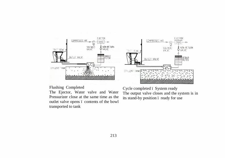
213
Flushing Completed The Ejector, Water valve and Water Pressurizer close at the same time as the outlet valve opens – contents of the bowl transported to tank
Cycle completed – System ready The output valve closes and the system is in its stand-by position – ready for use

Limitations: Does not work in the event of loco changeover/failure, due to non-availability of compressed air. Does not work in stabled condition in platforms. The system needs better monitoring as several indicators and alarm signals are outputted by the system. If required conditions are not met, the system stops the toilet. Elaborate infrastructure needs to be built up for disposal of effluents from the retention tank.
6.3 Zero Discharge Toilet System:
This toilet works on the principal of solid liquid separation with solid portion stored- evacuated- transfered and dump into pits for composting and liquid portion filtered, treated, recycled for flushing purpose. These toilets have been developed by a consortium consisting of RDSO, IIT/Kanpur & URBANE Industries, Chennai under TMRS Projects.

215

216
Advantages of the system: There is no effluent discharge on track and has effective non-degradable waste segregation system. Water is recycled for flushing. Complete Environment friendliness as waste is converted to fertilizer. Robust design. Disadvantages: This needs evacuation frequently and extensive ground facilities like pits, transfer pumps etc for composting. It has higher operational cost. Quality of recycled water for flushing needs improvement as it has mild stink. Detention of rakes at pit lines is more.
6.4 Aerobic type biological Toilet:
Indian Railways has tried out bio digesters imported from M/s Microfore, USA where aerobic bacteria are used for decomposing the waste into gases and water. Liquid is discharged on the ground after chlorination. This system has been successful but periodic replenishment and high initial as well as maintenance cost are the stumbling blocks.

217
Limitations: The toilets has foul smell, there is lack of non-bio-degradable separation system. There is choking due to accommodation of non-bio-degradable. It requires periodic replenishment
6.5 IR-DRDO Anaerobic biological toilet system:
In this technology anaerobic bacteria is used for de-composition. DRDO developed these bacteria for use in high altitudes areas like Siachen Glacier where de-composition of waste is not possible by natural process. This bacteria once charged does not require replenishment for long time and system is maintenance free. Difference between aerobic bacteria and anaerobic bacteria: Aerobic Bio-degradation Anaerobic Bio-degradation Forced aeration/agitation is essential which is energy intensive
No aeration is required
Incomplete aeration (partial aerobic condition) leads to foul smell
Complete anaerobic condition
Not effective in pathogen inactivation
More than 99% pathogen inactivation
Cannot tolerate detergents/phenyle Anaerobes can even degrade detergents/phenyle
Generates large amount of sludge Sludge generation is very less
Repeated addition of bacteria/enzyme is required for process
One time bacterial inoculation is enough
Maintenance & recurring cost is high
Minimal maintenance & no recurring cost
Fecal matter: Having 80% of bacteria (both aerobic & anaerobic & reducing in nature), Water and Non-degradable waste.


Anaerobic Bio digester provided under the toilet in the coaches: The size of the tank is 1150 x 720 x 540 mm, made up of stainless steel, under slung on mounting brackets in the coaches. The tank has 6 partition walls inside the tank (seven chambers) Poly grass mat for protection of bacteria inside the partition walls Ball valve with handle for operation for making toilet direct discharge in case of chocking Total volume of tank – 400 lts Effective volume of tank – 300 lts Empty tank weight – 110 Kgs Full tank weight – 410 Kgs Height from Rail level – 225 mm

220
There are Seven chambers in the tank. First chamber has grill partition so that non-bio-degradable objects do not pass to further chambers. Fecal matter in slurry form goes from 1st chamber to 2nd chamber through a pipe (from bottom of first chamber). Slurry flows from 2nd chamber to 6th chamber through slits in the partitions. From 6th chamber to 7th chamber it flows through a pipe (from bottom of the 6th chamber). From 7th chamber to the chlorinator it flows through a pipe (from top of the 7th chamber).Finally chlorinated water discharged to the ground. Nylon matting is provided on all walls for colonization of bacteria. Four variants and its Limitations: # Design variants Limitations
1 Varaint-1 Having PLC with electronics and pneumatics
Failure and theft of PLC. Non availability of electricity and air every time. High cost of AMOC. Frequent attention similar to CDTS. Leakage through flapper valve.
2 Varint-2 Provided with manual slider valve for removing the choke, without electronics and pneumatics
No problem in maintenance, except for opening in case of choking with foreign object. It is required to be opened by going between adjacent coaches. (Modifications are under trial with provision of opening arrangement from inside the toilet itself.)

221
3 Varaint-3 Provided with smaller dia opening to the tank, no fail safe arrangement, without electronics & pneumatics
Being no fail safe mode, all foreign objects going to tank, thus tank is with full of garbage. Frequent choking problems.
4 Vraint-4 Provided with manual flapper with solid liquid separator.
Manual flapper leakage Solid liquid separator groove blockage thus not functions as desired.
SALIENT FEATURES: Bad smell in toilets from the tanks is not there. fecal matter in the tank is not visible. Infestation of cockroaches & flies is nil in this system. Clogging of digester is not noticed. The effluent is free from odour and solid waste. There is reduction in pathogens by 99% and organic matter by 90%. No maintenance and adding of bacteria/ enzyme is required during service. Removal of solid waste is also eliminated. Use of phenyl/ cleaning agents is permitted up to 100ppm. Cleaner under gear components and end body, for hygienic working in maintenance lines. Improvements in the designs: The sliding valve is replaced with ball valve. In present design, if toilet chokes, the failsafe valve cannot be made operational in the entire journey as ball valve cannot be

222
operated from inside the toilet. Further, in case train is standing at a station toilet adjacent to platform cannot be made operational because of space constraint for operation of valve. Hence the valve is provided with arrangement to be opened with a foot pedal from inside the toilet itself in the case of choking during run, and it automatically closed on release of the foot. One dust bin is provided inside the toilet which can be used for disposing the non bio degradable items, as the passengers have tendency to throw the objects into the lavatory pan and cause choking. For awareness among the passengers, particularly Non AC passengers, Pictorial stickers are provided inside the toilet to educate passengers for Do’s and Don’ts. Brief about bacteria (Anaerobic bacteria): Can process doubling its population within 6 to 8 hours. Dominates and decompose fecal matter in to liquid and gases. Can be kept for 3-4 months at ambient temperature. Can withstand sub zero temperature as well as upto 60 degree centigrade. Cold temperature would not affect the inside process because Anaerobic process is exothermic in nature hence in cold regions heat will be available inside the chamber because of chemical process Maintenance of Bio-toilet system: Inspect complete toilet system including under slung equipments visually. Check the toilet system for any deficiency. Clear the chocked chute in bio-toilets and preferably keep the system in direct discharge mode during cleaning the toilets. Toilets fitted with bio-digester should be preferably cleaned by pressurised water cleaning system so as to minimise the water usage. Charge the chlorination chamber with chlorine tablets as per the requirement. Collect the samples as per the schedule and sent for laboratory

223
tests. Charge the bio-culture if required based on the test reports of the samples collected Guidelines for handling the bacteria: Wear gloves while handling bacterial culture. Store bacterial culture in container with lid which can be closed. During transportation, lids should be tightly closed. During storage, lids should be kept loose to facilitate escape of gas generated inside the container. Do not mix detergents/acids with bacteria at any stage during use. Clean/sanitize hands with detergents/soap after handling the bacteria.

Testing of Effluents of Bio-toilet:
Details Set target Sampling qty
Frequency of sampling Remarks
pH value 6- 9 50 – 100 ml 90 days To be tested in Laboratory
/at site Total Solids (TS) < 750 mg/100 ml 25 ml 90 days To be tested in laboratory Total Dissolved Solids (TDS) < 350 mg/100 ml 25 ml 90 days -do-
Total Volatile Solids (TVS) < 500 mg/100 ml 25 ml 90 days -do-
Chemical Oxygen Demand (COD)
< 2000 mg O2/100 litres 5 – 10 ml 90 days Laboratory/DRDO/ Govt
approved labs
Fecal Coli Forms count
> 99% reduction (less than 108/100 ml)
10 ml 90 days Govt approved labs only

225
Storage of sample: Maximum storage Determination Container Minimum
sample(ml) Sample type Preservation Recomended Regulatory
pH Plastic or Glass 100 Composite Analyse
immediately 15 min 15 min
Total solids Plastic or Glass 25 – 50 Composite Refrigeration
(4-7o C) 7 days 2 – 7 days
Total dissolved solids
Plastic or Glass 25 – 50 Composite Refrigeration
(4-7o C) 7 days 2 – 7 days
Volatile solids Plastic or Glass 25 – 50 Composite Refrigeration
(4-7o C) 7 days 2 – 7 days
Chemical oxygen demand
Plastic or Glass 5- 50 Composite
Analyse immediately or add H2SO4 to pH <2.0 and refrigerate
7dyas 28 days
Total fecal coli forms count
Plastic or Glass 1 – 10 Composite
Add sodium thiosulphate and refrigerate (4-7o C)
1 day 1 day

Sample shall be collected on quarterly basis and sent for testing Samples will be collected randomly from a lot of 5% coaches of the total coach holding but minimum one coach of each type at an interval of every three months during the trial period Sampling will start after coach has been in passenger service for 10 days or more Collect samples from the bio digester 30 minutes after the train becomes stationery/still Open the sample port and let water drain for 2 minutes to remove settled solids particles and to ensure that sample is representative of the system The samples should be collected and sealed in presence of Railway representative. Atleast one test every quarter shall be carried out in Govt lab In case the samples do not meet requirement, test shall be repeated after taking necessary corrective actions within a fornight Sample shall be collected in 2 litre plastic bottle by simply opening the knob provided in the sampling port Date and time of sampling and coach No. must be mentioned on the bottle Sample collected in the bottle shall be transported to lab at the earliest but not later than 24 hours after collecting of the sample During POH of the coach fitted with Bio toilet, the tank shall be removed from the coach and kept at safe place and refitted on the same coach after other attention on the coach. In case there is any damage or leakage the inoculum shall be drained and the tank repaired. After repairing and fitting on the coach it has to be refilled with required level of fresh culture (approx 120 litres) before dispatch of coach.

227
7 FREIGHT STOCK
Rolling stock used exclusively for transport of goods is termed as freight stock. Freight Stock are broadly classified either according to their under gear or according to utility. Classification according to under gear: Four wheeler wagon Bogie wagons Four wheeler wagons: At present only Brake van is in service, other 4 wheeler wagons ike tank wagon and CRT wagons are phased out. Bogie wagons: There are four different types of bogies used in wagons. Diamond frame bogie, Cast steel Bogie, UIC fabricated bogie CASNUB Bogie Classification according to utility: Open wagons, Covered wagons, Flat wagons,Hopper wagons Well wagons, Container wagons, Tank wagons, Brake vans Open wagons: These are wagons are used for transportation of coal, ore, limestone’s etc. which does not require protection from rain. The wagons are provided with flap doors for ease of loading/unloading of consignment. Covered wagons: The consignments, which required to be protected from rain etc; are transported in covered wagons. These wagons generally carry food grains, cement, fertilizers, fruits & vegetables etc. Flat wagons: These wagons are without side walls and are generally used for carrying steel coils, billets, rails sleepers etc.

228
Hopper wagons: These are special wagons designed for Rapid discharge from bottom. These are used for transporting coal and ballast. Well wagons: These wagons have well shaped under frame and are used for larger consignments like military tanks, heavy equipments etc. Container wagons: These are special flat wagons designed for handling containers. Tank wagons: These are wagons designed to carry liquids like petroleum products, milk, edible oils, etc. Brake vans: These are guards van used with freight trains as last vehicle
7.1.1 OPEN WAGONS
BOY: Designed in 1967 for heavy minerals. Axle Load - 22.9t. Cast Steel Bogie. It has no doors. Speed 65/75 Kmph.

229
BOY EL: Introduced in 2006 for operation at 25t Axle Load. Bogie -Casnub 22NLC. Differentiated from BOY by an Olive Green Band. Speed restricted to 50/65 Kmph. BOXN: Designed in 1980 for coal. Axle Load - 20.32t. CASNUB Bogie, Speed 75/80 Kmph.
BOXN M1: In 2005 for increasing the CC up to CC+8+2t, suspension of BOXN is augmented by providing additional springs. A caption “Fitted with additional springs for Axle Load of 22.2t” in the centre of the wagon in golden yellow is printed to differentiate. Bogie side frame is also painted with Golden Yellow band. Speed 70/80 Kmph for CC+6+2t & 60/80 Kmph for CC+8+2t. BOXN EL: Introduced in 2006 for operation with 25t Axle Load. Bogie - Casnub22 NLC. Differentiated from BOXN by an Olive Green Band. Speed restricted to 50/65 Kmph.

230
BOXN HS: Designed in 2000. Variant of BOXN with Casnub 22HS bogie for increasing speed. Differentiated from BOXN by a Golden Yellow band. Speed 100/100 Kmph.
BOXN HSM1: In 2005 for operation up to CC+8+2 t, suspension of BOXNHS modified by providing two additional inner springs. Differentiated from BOXNHS by a caption “Fitted with additional springs for Axle Load 22.82t” in centre of the Golden Yellow band. Bogie side frame also provided with Golden Yellow band. Speed 75/90 Kmph for CC+6+2t and 60/90 Kmph for CC+8+2t. BOXN CR: Designed in 1999. Material of body of BOXN changed to stainless steel (IRS: M 44). Other parameters are same as BOXN.

231
BOXN R: Designed in 2007. It is upgraded rehabilitated version of BOXN. Entire superstructure of MS replaced with Stainless steel (IRS: M 44). Height is177 mm more than BOXN. Carrying capacity increased by 6t. Nine stanchions provided, instead of 6 in BOXN. Axle Load - 22.9t.
BOXNHA: This wagon was designed in 2001 for transportation of coal with an axle load of 22.1t. Bogie - IRF 108HS. Its height is more than BOXN. Speed at 20.32t and 22.1t Axle Load 100/100 Kmph and at 22.82t Axle Load 60/65 Kmph. BOXN LW: Designed in 1988 to meet the requirement of higher pay to tare ratio. Axle Load - 20.32t. Casnub22HS bogie, Width is 50 mm more than BOXN. Stainless steel (IRS: M44) & corton steel (IRS: M41) used in body and under frame and Cold Rolled Formed (CRF) sections were used in design to reduce the tare weight of the wagons. Manufacturing of this wagon started in 2005. Speed 100/100 Kmph. BOXN LWM1: In year 2008, design and Suspension of BOXNLW modified for operation up to CC+8+2t. Speed 60/65Kmph for both CC+6+2t and CC+8+2t.

232
BOXN HL: Designed in year 2005, 250mm longer, 76mm higher & 50mm wider than BOXN. Axle Load - 22.9t. Casunub22HS Bogie. Stainless steel (IRS:M44) and CRF section used in body and under frame to reduce tare weight (20.6t). Has been provided with improved quality coupler and draft gears. PU painting is used. Initially red oxide colour specified, later on changed to phirozi blue. In red oxide colour wagons ‘SS’ written on side in a circle in phirozi blue colour for identification. Speed 75/100 Kmph.
BOST: Designed in 2000 for long steel products. Axle Load - 20.32t. CASNUB 22HS Bogie. Speed 75/80 Kmph. BOST M1: In 2006 for operation up to CC+6+2t, it is modified by providing additional springs. Differentiated from BOST by a caption “Fitted with additional springs for Axle Load 22.32t” in centre of the wagon in Golden Yellow. Speed 60/65 Kmph.

233
BOST HS: Designed in 2004. Variant of BOST with Casnub 22HS (Mod-1) bogie for increased speed. It is differentiated from BOST by a Golden Yellow Band. Speed 100/100 Kmph. BOST HS M1: In 2007 for operation up to CC+6+2t. it is differentiated from BOSTHS by a caption “Fitted with additional spring for Axle Load 22.32t” in centre of the Golden Yellow Band. Speed 60/80 Kmph. BOST HS M 2: Designed in 2006 for increasing speed. Axle load 22.32t. Variant of BOSTHS with CASNUB 22HS (Mod-II). Speed 60/100
7.1.2 COVERED WAGONS
BCN: Designed in 1984 for transportation of bagged commodities. Axle Load 20.32t. present stock is mostly with CASNUB 22NLB, Speed 75/80 Kmph.

234
BCN M 1: Introduced in 2006 for operation up to CC+8+2t. it is differentiated from BCN by a caption “Fitted with additional springs for Axle Load 22.82t” in centre of the wagon in Golden yellow. Golden Yellow Band is provided on bogie side frame also. Speed 75/80 Kmph for CC+6+2t and 65/80 Kmph for CC+8+2t BCN A: Designed in 1990 by reducing the length of BCN wagon and increasing height, there by increasing the number of wagons in a rake to 44. Axle Load 20.32t. Bogie is CASNUB 22NLB, Speed 80/80 Kmph.
BCNA M 1: Introduced in 2006 for operation up to CC+8+2t. it is differentiated from BCNA by a caption “Fitted with additional springs for Axle Load 22.82 t” in centre of the wagon in Golden yellow. Golden Yellow Band is provided on bogie side frame also. Speed 75/80 Kmph for CC+6+2t and 65/80 Kmph for CC+8+2t BCNA HS: Designed in 2001, variant of BCNA with CASNUB 22HS bogie for increased speed. It is differentiated from BCNA by a Golden yellow band. Speed 100/100 Kmph. BCNA HSM 1: Introduced in 2006 for operation up to CC+8+2t. It is differentiated from BCNAHS by a caption “Fitted with additional springs for Axle Load 22.82t” in centre of the wagon in

235
Golden yellow. Golden Yellow Band is provided on bogie side frame also. Speed 75/100 Kmph for CC+6+2t and 65/100 Kmph for CC+8+2t. BCN HL: Designed in2006 for bagged commodities. Axle Load 22.9t. Length is further reduced and both width and height increased compared to BCNA. Hence number of wagons per rake increased to 58. Bogie is of CASNUB 22 HS type. Stainless steel (IRSM: M44) and CRF sections used in body and under frame construction to reduce the tare weight. Has been provided with improved quality coupler and draft gears. PU painting of Phiroziblue colour is used. Speed 65/65 Kmph.
BCCN/BCCN A/BCCN B: BCN variants for carrying bulk cement (not packed in bags). Loading is through ports at the top; unloading via chutes at the bottom.

236
NMG: These are not narrow-gauge wagons, despite the classification code. The class code 'NMG' stands for 'New Modified Goods' These are single-decker automobile carriers constructed out of old ICF and BEML passenger coaches. The design is not entirely uniform but generally all the windows and doors on the side walls are removed and the opening closed. End body is modified by providing doors to allow vehicles to be driven into it.
7.1.3 FLAT WAGONS
BRN: Designed in 1992 for transportation of rails and heavy steel products. Axle Load 20.32t. provided with CASNUB 22 NLB, Speed 75/80 Kmph.
BRN A: Designed in 1994, improved version of BRN. The design is riveted cum welded construction. Higher pay to tare ratio,

237
compared to BRN. Other parameters are same as BRN. Speed 75/80 Kmph. BRN AHS: Designed in 2001. Variant of BRNA with CASNUB22HS bogies for increased speed. Speed 100/100 Kmph.
BFNS: Designed in 2002 especially for transportation of hot rolled/cold rolled coils, plates, sheets and billets etc. This is the first wagon designed in Indian Railways to carry point load. Provided with CASNUB 22HS bogie, Axle Load 20.32t. Speed 100/100 Kmph.
BRHNEHS: This bogie rail wagon was designed in 2004 for use of Engineering department of various Zonal Railways for Track

238
Relaying Train (TRT), specially for loading RCC sleepers. Axle Load 20.32t. provided with CASNUB 22HS Bogies. The design was provided with Transition CBC and air brake system. Speed 50/65 Kmph.
7.1.4 HOPPER WAGONS
BOBSN: Designed in 1994 for transportation of iron ore, Axle Load 22.9t. Provided with modified CASNUB 22NLB bogie. It is provided with side discharge. Speed 75/75 Kmph.

239
BOBSNM1: In 2006 for operation at A/L 25t, suspension of BOBSN modified by providing 4 additional inner springs, Bogie renamed as Casnub22NLC. Speed 50/60. BOBR: Designed in 1986 for transportation of Coal, it is provided with bottom discharge. Axle Load 20.32t. Provided with CASNUB 22NLB bogie, Speed 80/80 Kmph.
BOBRM1: Introduced in 2006 for operation up to CC+6+2t. it is differentiated form BOBR by caption “Fitted with additional springs for A/L 22.32t” in centre of wagon in Golden Yellow. Golden Yellow Band is provided on bogie side frame also. Speed 70/75 Kmph. BOBRN: Designed in year 1991 by reducing the length of BOBR wagon to increase the number of wagons in a rake to 58 (from 53 of BOBR). Axle Load 20.32t. provided with CASNUB NLB bogie. Speed75/70 Kmph.

240
BOBRNM1: Introduced in 2006 for operation up to CC+6+2t, it is differentiated from BOBRN by a caption “Fitted with additional springs for A/L 22.32t” in centre of wagon in Golden Yellow. Golden Yellow Band is provided on bogie side frame also. Speed 70/80 Kmph. BOBRNHSM1: Designed in 2006 for Axle load of 22.32t. Variant of BOBRN with modified CASNUB 22HS Bogie for increased speed. Instead of BOBRNHS this (BOBRNHSM1) was manufactured. Speed 60/100 Kmph. BOBRNEL: Introduced in 2008 for operation at Axle Load of 25t. It is differentiated from BOBRN by an olive Green band. Speed restricted to 50/65 Kmph. BOBYN: Designed in year 1996 for transportation of ballast for engineering department. It has chutes at side & bottom for discharging ballast on both sides and centre of rails. Provided with CASNUB 22NLB Bogie, Axle Load 20.32t. Speed 75/75 Kmph.
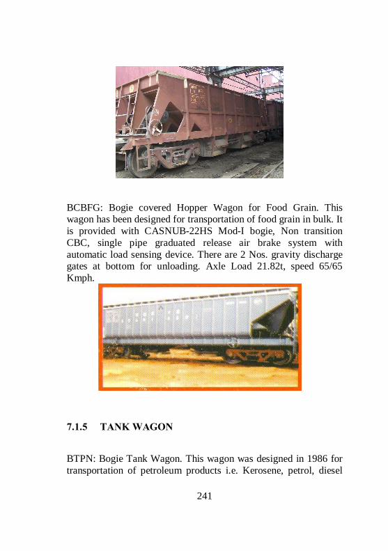
241
BCBFG: Bogie covered Hopper Wagon for Food Grain. This wagon has been designed for transportation of food grain in bulk. It is provided with CASNUB-22HS Mod-I bogie, Non transition CBC, single pipe graduated release air brake system with automatic load sensing device. There are 2 Nos. gravity discharge gates at bottom for unloading. Axle Load 21.82t, speed 65/65 Kmph.
7.1.5 TANK WAGON
BTPN: Bogie Tank Wagon. This wagon was designed in 1986 for transportation of petroleum products i.e. Kerosene, petrol, diesel

242
and naphtha. Axle Load 20.32t. CASNUB 22 NLB bogie. Speed 80/80 Kmph.
BTALN: Bogie Ammonia Tank WagonThis tank wagon was designed in 1984 for transportation of anhydrous liquid ammonia. Provided with UIC Bogie, Axle Load is 20.32t. Speed 65/65 Kmph. BTPGLN: This wagon is designed for transportation of LPG. Provided with Air brake and CASNUB 22NLB bogie, Axle Load is 20.32t. Speed 75/80 Kmph.
BTCS: Bogie Caustic Soda Tank Wagon. This wagon was designed in 1980 for transportation of Caustic soda. Bogie CASNUB 22W. Axle Load 20.32t. Speed 65/65 Kmph.

243
BTAP: Bogie Alumina Tank Wagon This wagon was designed in 1982 for transportation of Alumina powder. It is gravity loaded and has provision of fluidizing for evacuation. Present stock is fitted with CASNUB 22NLB bogie, Single pipe Air Brake System & non transition high tensile CBC. Axle Load 20.32t. Speed 65/65 Kmph.
7.1.6 BRAKE VAN
BVZI: Bogie Brake Van This 8-wheeled brake van was designed in 2004 with ICF bogie to achieve comfort level(Ride Index) equivalent to loco for goods

244
guard and capable of running at 100 Kmph. The brake van is 5 meter longer than BVZC brake van.
BVZC: 4 Wheeler Brake Van with Air Brake This 4-wheeled brake van is fitted with 9 plated laminated bearing springs. Wheel base of 5400 mm. Fitted with cylindrical roller bearing wheels. Auxiliary reservoir capacity is 75 ltrs. Brake cylinder dia 304mm/12 inches. Speed potential 100 kmph.

245
7.1.7 CONTAINER WAGONS
BFKN: Bogie Container Flat Wagon. Broad gauge Bogie Container flat wagon type BFKN is modified version of BFKI wagons, which are in operation on IR from 1975 for transportation of containers (max pay load of 48t). Operating speed is 75 kmph. Modified BFKN (Air brake & enhanced pay load) wagons can carry payload of 61t. these wagons are fitted with indigenous designed Retractable Anchorage Locks (patented) to secure containers.
BLCA/BLCB: Bogie Low Platform Container Flat Wagon. Designed in 1994 for transportation of 20’ & 40’ long ISO containers with operation speed of 100 kmph. Lower height of under frame floor from R/L. has been achieved with introduction of hybrid design of bogie frame, bolster and use of smaller diameter wheel in LCCF 20(C) bogie, Axle Load 20.32t. Speed 100/100 Kmph. Provided with Automatic twist lock for securing of containers on the wagon.

246
BLLA/BLLB: Bogie Low Platform Longer Container Flat Wagon. Designed jointly by RDSO & RITES in 2001 for transportation of 22’, 24’ & 45’ containers. There is provision for carrying 20’ & 40’ long ISO containers also. Except the under frame the bogies are all of BLC wagons. Axle Load is 20.32t. Speed 100/100 Kmph.
DOUBLE STACK CONTAINER OPERATION: In March 2006 double stack container train operation started with restricted speed of 75kmph. This was for the first time in the world that double stack container train operation of flat wagon was done. Speed 75/75 Kmph. BLCAM/BLCBM: In the year 2007 bogie of BLC wagon was modified by providing upgraded side bearer, upgraded friction

247
wedge & 2 additional inner springs for double stack container operation with Axle Load of 22t & 100kmph speed. BCACM: In the year 2007, to meet the immediate requirement of auto car industry, design of existing container flat wagons (A type & B type) modified by provision of a suitable bi-level structure for transportation of auto cars. One rake can carry up to 270 auto cars. Two such rakes converted by Jagadhari Workshops are in operation.

Details
Description Code Tare (Ton)
Pay load (Ton)
Length over CBC
Height from RL
Type of coupling
Bogie covered wagon Bogie covered wagon BCN 27.20 54.08 15429 3788 Straight CBC Bogie covered wagon BCNA 24.55 56.73 14450 4017 -do- Bogie covered wagon – stainless steel
BCNAHL 20.80 70.80 10963 4305 -do-
Bogie covered wagon with high speed bogie
BCNAHS 24.60 56.68 14450 4017 -do-
Bogie covered wagon-stainless steel
BCNHL 20.80 70.80 10963 4305 -do-
Bogie covered with vacuum brake BCXC 28.50 52.78 15782 3762 -do- Bogie flat container wagons Bogie flat container wagon BFKN 20.50 60.78 14682 1269 -do- Bogie low platform container wagon (A-Car)
BLCA 19.10 61.00 14566 1009 Straight CBC at one end and slack less coupler at other end

249
Bogie low platform container wagon (B-Car)
BLCB 18.00 61.00 13165 1009 Slack less coupler
Bogie low platform longer container wagon BLL (A-Car)
BLLA 19.80 61.00 16161 1008 Straight CBC at one end and slack less coupler at other end
Bogie low platform longer container wagon BLL (B-Car)
BLLA 19.00 61.00 14763 1008 Slack less coupler
Hopper wagons Coal/Ore wagon with bottom discharge facility
BOBR 26.00 55.28 11600 3735 Straight CBC
Bogie open bottom rapid discharge hopper wagon
BOBRN 25.61 55.67 10600 3735 -do-
Bogie open bottom rapid discharge hopper wagon with HS bogie
BOBRNHS 25.61 55.67 10600 3735 -do-
Bogie open ballast wagon BOBYN 26.78 54.50 12000 3050 Transition CBC Bogie open ballast wagon with HS bogie
BOBYNHS 26.78 54.50 11647 3050 -do-
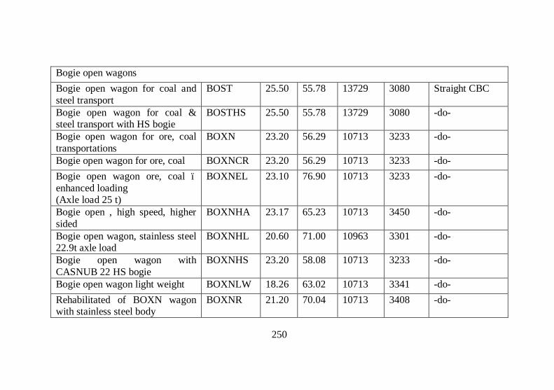
250
Bogie open wagons Bogie open wagon for coal and steel transport
BOST 25.50 55.78 13729 3080 Straight CBC
Bogie open wagon for coal & steel transport with HS bogie
BOSTHS 25.50 55.78 13729 3080 -do-
Bogie open wagon for ore, coal transportations
BOXN 23.20 56.29 10713 3233 -do-
Bogie open wagon for ore, coal BOXNCR 23.20 56.29 10713 3233 -do- Bogie open wagon ore, coal –enhanced loading (Axle load 25 t)
BOXNEL 23.10 76.90 10713 3233 -do-
Bogie open , high speed, higher sided
BOXNHA 23.17 65.23 10713 3450 -do-
Bogie open wagon, stainless steel 22.9t axle load
BOXNHL 20.60 71.00 10963 3301 -do-
Bogie open wagon with CASNUB 22 HS bogie
BOXNHS 23.20 58.08 10713 3233 -do-
Bogie open wagon light weight BOXNLW 18.26 63.02 10713 3341 -do- Rehabilitated of BOXN wagon with stainless steel body
BOXNR 21.20 70.04 10713 3408 -do-

251
Open gondola wagon (1967) BOY 20.71 70.89 11929 2450 -do- Open gondola wagon with CASNUB 22 NLC bogie with 25 T axle load
BOYEL 20.70 79.30 11929 2450 -do-
Bogie open wagon with Vacuum trolley
BOXC 25.00 56.28 13729 3161 -do-
Flat wagons Bogie flat wagon for steel loading (1998)
BFNS 26.71 54.57 14645 -do-
Bogie flat rail wagon BRN 24.39 56.88 14645 2544 -do- Bogie flat rail wagon BRNA 23.54 57.73 14645 -do- Bogie flat rail wagon with HS bogie
BRNAHS 23.54 57.73 14645 -do-
Bogie flat rail wagon with UIC trolley
BRH 24.38 56.90 14986 -do-
Bogie tank wagons Bogie tank wagon designed for transportation of Ammonia
BTALN 49.13 32.13 17529 4265 -do-
Bogie tank wagon for transportation of Alumina powder
BTAP 27.31 53.96 12329 4350 -do-

252
Bogie tank wagon for Caustic soda
BTCS 26.00 55.28 10713 4110 -do-
Bogie tank wagon for petroleum products
BTPN 27.00 54.28 12420 4265 -do-
Bogie brake van 8 wheeler brake van with ICF bogie
BVZI 23.50 14469 3894 -do-
Four wheeler brake van BVZC 13.80 9469 3894 -do-

7.2 MAINTENANCE PRACTICES FOR FREIGHT STOCK
The life of a wagon is about 30 to 40 years. For keeping the wagons in good working condition, depending upon type of wagons, Periodical Overhauling (POH) is given at an interval 4 to 6 years. In between POHs, Routine Overhauling (ROH) of the wagons are done at specified intervals at ROH depots by providing extra attention to these wagons compared to other normal intensive examination. Wagons normally do not run in defined link and run from one part of our country to another as per traffic requirements. The maintenance staff attending the wagons for normal intensive examination makes out from the last POH date and place which is predominantly displayed on Wagon body whether it is due for schedules, and in case it falls due, the same is detached from service and sent to nearest depot or workshop. It is ensured that normally no wagons overdue for POH, ROH or other schedules are put in to service for traffic. POH and special repairs are attended in workshops and ROH of wagons is given at Depots equipped with sufficient facilities and nominated for taking up the ROH repairs. Sick lines at wagon maintenance depot attend to other repairs arising during intensive examination of the freight trains. Thus there is a 3 tier Maintenance System for Freight stock. Maintenance in yard/Sick lines ROH depots POH workshops for wagon.

254
7.2.1 YARD MAINTENANCE
The efficient working of freight stock is closely linked to the standard of yard maintenance. Several factors are responsible for good and quality examination/repair in the yard. The method of examinations is described in the succeeding paragraphs. Steps of Intensive Examination: Rolling examination including axle box feeling. Intensive examination of origination trains including repairs, detachment of damaged/sick wagons, brake power testing etc. Issue of intensive Brake power certificates after ensuring brake continuity of the formed rake.
7.2.1.1 ROLLING IN EXAMINATION:
All terminating trains should be given rolling in examination while entering a station/yard with a train examination depot. To carryout this examination a Train examiner and his staff should take up positions on both sides of the lines short of the normal halting place on which the train is to be received. The following inspection should be carried out during the rolling in examination The rolling in examination must be conducted to detect any skidded wheel. In motion inspection and observation of under gear of wagons for any loose or dangling components. Immediately after the train has comes to a halt, all axle boxes should be felt within 20 minutes of the train arrival and those axle boxes which are found running at high temperature, should be marked for opening/checking at the time of examination and attention if necessary. Examination of any abnormal behaviour of any of the vehicles or any other observation which may relate to unsafe working condition.

255
Defect in the brake system or faulty manipulation by the driver may cause skidding of wheels. Incoming BPC should be collected by yard C&W staff.
7.2.1.2 INTENSIVE EXAMINATION AND REPAIRS
Once, the train has been offered for examination by Traffic Department, the rake should be protected at both the ends before undertaking the following examination and repair activities: Inspection and repairs of running gear fittings. Inspection and repairs of brake gear and suspension gears. Inspection and repairs of draw and buffing gear. Checking and making good the deficiency of safety fittings, safety brackets, safety loops, etc. Visual examination of under frame members, body, checking and proper securing of doors especially of covered wagons. Correct functioning and positioning of empty load device. Identify any warm box in the plain bearing axle box and should be opened for examination and attention, if found warm. Roller bearing stock found running at high temperature may be taken to sick lines for further attention. Look for abnormal and unequal buffer heights; condition of shank wear plate knuckle, etc. to the extent it is possible to detect by visual examination. In case of doubt, the buffer height should be measured. CBC wear or deficiency of parts to be marked and their operation to be checked. The bogies complete ie., side frames and bolsters to be visually examined for cracks and missing parts. All springs, snubbers, spigots, centre pivots fastening, side bearers to be checked for defects, if any. Thorough check of Air brake components like brake cylinders, distributor valves, auxiliary reservoir control chambers and other pipe joints should be carried out to ensure that these are in proper working order. Isolating cocks and angle cocks to be checked for

256
proper position. Brake cylinder should be released and checked for prescribed piston stroke for empty and loaded position. After brakes are released, the wheel profile should be examined visually. If any defect is noticed, it should be checked with tyre defect gauge and wagon to be marked sick for wheel changing, if required. If bent axle is suspected wheel gauging must be done. Examine brake rigging components with special attention to brake beam deformation and wear on integral brake shoe bracket. Check intactness of the pull and push rods with pins, washers, split pins and cotters, etc. Hand brakes must be checked for smooth and effective operation. Brake blocks should be replaced on reaching condemning thickness. Cast iron brake blocks as per RDSO drawing No. WA/BG-6158 with latest alteration or composite brake blocks should be used. Worn out composite brake blocks should be replaced with composite brake blocks. To ensure correct fitment of brake blocks, only spring steel key as per RDSO Drg. No. W/BG-6150 should only be used. After fitment of brake block and key on brake head fitment of split pin should be ensured. Correct fitment of washers, bulb cotters and all brake gear pins to be ensured. Brake power should be tested as per rule E-5 of Appendix E of the IRCA Rules Part III for vacuum brake stock and as per rake testing procedure. At certain nominated yards, vacuum braked trains moving over falling gradients in ghat sections shall be subjected to Balanced Vacuum Test. The detailed procedure for carrying out this test is given in IRCA Part III, 2000- Appendix E. Examination of loaded stock should be done as per IRCA part-III. Examination of tank wagons should be done as per IRCA Part-III. Where a rejectable defect can not be attended to on the train in the yard, the wagon shall be damaged labelled for attention in the sick line.

257
7.2.1.3 ISSUE OF INTENSIVE BRAKE POWER CERTIFICATE;
All freight trains after being subjected to intensive examination will be given a Brake Power Certificate. To distinguish the brake power certificates, the colour of vacuum brake and air brake stock is Pink and Green respectively. In Air Brake stock, the colour of BPC for Premium End to End will be green and for Closed Circuit rake will be yellow in colour. On originating BG and MG vacuum goods trains, there shall be 85% and 80 % effective brake power respectively, subject to observance of any higher limit prescribed by the Railways for particular Ghat /other sections. The minimum originating brake power for air braked goods trains, running on end-to-end pattern of examination, shall be 85% except wherever local instructions have specified higher level of brake power to meet specific requirement. Exception shall only be made after prior approval of Chief Rolling Stock Engineer has been obtained for each individual case. The originating brake power for premium End to End rakes shall be 95%. The originating brake power for goods trains running in close circuits shall be 100 % with adequate brake block thickness for the extended run of 6000 Kms. As far as possible, the close circuit air brake rakes should be formed by off-ROH and off-POH wagons for better monitoring. No fresh Brake Power Certificate shall be issued during revalidation. No Safe-to-Run BPC shall be issued from nodal points. No Safe-to-Run BPC shall be issued for vacuum brake stock either in empty or in loaded condition. Brake pipe pressure required in the air braked train should be as follows:
No. of wagons On Locomotive On last wagon Up to 56 5.0 Kg/Cm2 4.8 Kg/Cm2 Beyond 56 5.0 Kg/Cm2 4.7 Kg/Cm2

258
The minimum level of vacuum should be 46 cm in engine and 38 cm in the brake van. The level of the vacuum on the engine and the brake van along with the percentage of effective brake cylinders must be recorded on the vacuum certificate and countersigned by the Driver and the Guard. The following procedure should be followed to issue the BPC after attachment of the locomotive: All BP hoses/ hose pipes on the train should be coupled up. The angle cocks in case of air brake stock at both ends of the wagon in brake pipe should be open except the angle cock at the end of brake van, which must be in closed position. In case of vacuum stock, hose pipe of the rear most vehicle should be kept on dummy carrier. Attach front wagon BP hose/ hose pipe to BP hose/ hose pipe of the locomotive. Ensure firmness and tightness of hoses with palm ends/universal coupling and clips. Attend to all leaks by replacing MU washer/IR washer, leaky hoses and angle cock assembly, if requisite BP pressure is not attained in the last vehicle. Inoperative or defective brake cylinders should be isolated by changing the isolating cock handle in close position.
7.2.1.4 TERMINATING EXAMINATION OF FREIGHT STOCK;
Examination of terminating load should be carried out as soon as the train has come to a halt. The examination would consist of the following: -

259
All under gear fittings including brake gear draw and buffing gear and spring gear, air brake, underframe, body, door mechanism, bogies, wheels, axle, etc. should be examined for being in sound condition and with all fittings intact. The tyre profiles should be checked to ensure that rejectable defects have not arisen. In doubtful cases, use of the tyre defect gauge should be made for this purpose. Vacuum brake cylinders should be tested in accordance with Rule E-5 of Appendix E of the IRCA Rules Part III. All vacuum brake cylinders should be released. Ensure functioning and position of load/empty device. Identify any warm box in the plain bearing axle box and should be opened for examination and attention, if found warm. Roller bearing stock found running at high temperature may be taken to sick lines for further attention. Thorough check of brake cylinders, distributor valves, auxiliary reservoir control chambers and other pipe points should be carried out to ensure that these are in proper working order. Isolating cocks and angle cocks to be checked for proper position. Brake cylinder should be released and checked for prescribed piston stroke in empty and loaded position. During terminating examination, special care should be exercised for any deficiencies, damages, leaky components, malfunctioning of distributor valves, brake cylinders, control and auxiliary reservoirs, angle cocks, BP hoses so that necessary replacement and repairs can be executed to minimise attention during outgoing examination. In case of loaded terminating trains which will be subjected to tippler for unloading, the Brake power available on train should be recorded deficiencies noticed should be chalk marked so that after unloading/Tippler operation, deficiencies can be identified and replaced during outgoing examination. Where a rejectable defect is not expected to be attended to on the train during the subsequent outgoing examination in the yard, the

260
wagon shall be sick marked/ damaged-labelled for attention in the sick line.
7.2.1.5 AIR BRAKE TESTING;
A rake consisting of air brake wagons should be tested with Air Brake Rake Test Rig. This test rig is used for testing the train in yard before attaching the engine. Connect the compressor through the test rig to the train & couple brake pipes. Ensure correct coupling with pipes so that there is no leakage of air from coupled joints. The coupling should be done with angle cocks in closed position. Open the angle cocks after coupling brake pipe. Open the angle cock of the brake pipe on all the wagons. Check for continuity of brake pipe by reducing and rebuilding brake pipe pressure. The verification should invariably be carried out through the pressure gauge provided in Guard’s Brake Van. After the brake pipe pressure has stabilised in the test rig and rearmost vehicle to the level indicated below. Reduce the brake pipe pressure from 5 kg/cm2 to 4 kg/ cm2 by operating the A9 valve handle towards application position. Brake pipe pressure required in the train S. No. No. of wagons On Locomotive On last wagon
1. Up to 56 wagons 5.0 Kg/Cm2 4.8 Kg/Cm2 2. More than 56 wagons 5.0 Kg/Cm2 4.7 Kg/Cm2
After the brake pipe pressure has been stabilised at 4 Kg/ cm2, isolate the source of supply to the formation. Wait for 60 seconds for temperature and gauge settlement. Then note the drop in pressure in the brake pipe gauge of test rig for five minutes. The drop in brake pipe pressure gauge shall not be more than 0.25 kg/cm2 per minute.
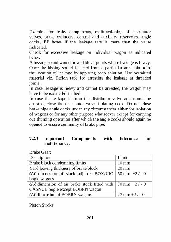
261
Examine for leaky components, malfunctioning of distributor valves, brake cylinders, control and auxiliary reservoirs, angle cocks, BP hoses if the leakage rate is more than the value indicated. Check for excessive leakage on individual wagon as indicated below: A hissing sound would be audible at points where leakage is heavy. Once the hissing sound is heard from a particular area, pin point the location of leakage by applying soap solution. Use permitted material viz. Teflon tape for arresting the leakage at threaded joints. In case leakage is heavy and cannot be arrested, the wagon may have to be isolated/detached In case the leakage is from the distributor valve and cannot be arrested, close the distributor valve isolating cock. Do not close brake pipe angle cocks under any circumstances either for isolation of wagons or for any other purpose whatsoever except for carrying out shunting operation after which the angle cocks should again be opened to ensure continuity of brake pipe.
7.2.2 Important Components with tolerance for maintenance:
Brake Gear: Description Limit Brake block condemning limits 10 mm Yard leaving thickness of brake block 20 mm ‘A’ dimension of slack adjuster BOX/UIC bogie wagons
50 mm +2 / - 0
‘A’ dimension of air brake stock fitted with CASNUB bogie except BOBRN wagon
70 mm +2 / - 0
‘A’ dimension of BOBRN wagons 27 mm +2 / - 0 Piston Stroke

262
Piston Stroke Type of wagon Empty Loaded
BOXN, BCN/BCNA, BRN, BTPGLN
85 mm +/- 10 130 mm +/- 10
BTPN 87 mm +/- 10 117 mm +/- 10
BOY 90 mm +/- 10 135 mm +/- 10
BVZC 70 mm +/- 10 BOX, BOI & BCX 130 mm 180 mm BOBRN/BOBR 100+/- 10 110+/- 10 Buffer Height: Description Limit
Max. 1105 mm (Empty) Buffer height from Rail level Min. 1030 mm (Loaded)
Spring Gear clearances for Vacuum Brake stock:
Sl. No
Description Clearances
1. Max. Clearance between shackle pin and shackle plate
3 mm
2. Clearance along the length of shackle Pin assembly with shackle plate, scroll iron, spring eye and cotter.
Max.1.5 mm
3 Wear on Shackle pin diameter and shackle plate hole
Max. 1 mm
4 Variation in camber between any two Springs on a bogie under load should not exceed
12 mm
5 Min. clearance between eye end & top surface 2 mm 6 Maximum variation in effective inside length 2 mm 7 Maximum permissible wear of the shackle at the
places of contact with stone 2 mm
8 Clearance between U/F side bearer and bogie side 4 to 7 mm

263
bearer of UIC Wear limits: Adapter Thrust shoulder 0.7 mm Adapter Crown lugs 4.0 mm Adapter crown seat 3.5 mm Adapter side lugs 3.0 mm Adapter sides 3.0 mm Side frame column friction plate 4.0 mm Side frame column sides 5.0 mm Side frame anti rotation lug 3.0 mm Pedestal crown roof 5.0 mm Pedestal crown sides 4.0 mm Pedestal sides 2.0 mm Pedestal jaw 4.0 mm Bolster liner wear limit 5.0 mm Bolster land surface 3.0 mm Bolster column sides – Inner/Outer 5.0 mm Friction Wedge Vertical Surface 7 mm Friction Wedge Slope Surface 3 mm Wheel & Axle Description Limit New Cond. Wheel dia (UIC bogie) 1000 mm 860 mm Wheel dia (CASNUB bogie) 1000 mm 906 mm Lateral clearance between axle box lug and horn cheek (UIC Bogies) 20 mm 25 mm
Lateral clearance available between spring buckle and horn gap stiffener for UIC 25 mm

264
7.3 Joint Procedure Order for Freight Trains
The pattern of freight train examination on S.W. Rly, has been reviewed and the recent changes in pattern of examination as advised by Rly. Board has been incorporated. Accordingly, the revised pattern of Freight Train Examination issued hereunder shall be implemented by all divisions on SWR with immediate effect. These instructions supersede all the instruction issued previously on the subject. The subject of train examination is divided into four categories- Closed Circuit Rake Premium Intensive End to End Non-closed circuit Intensive (End-to-End) Rake Departmental Rolling stock Table A,B,C & D indicate the pattern of freight train examination for “Closed Circuit “ , “Premium End to End “ , Non-Closed Circuit (Intensive End to End) “ & “Departmental “ rakes respectively and Table ‘E’ indicate the type of examination with the type of stock that will be under taken for examination by the depot mentioned therein.
7.3.1 Train Examination:
The system of train examination is divided into four types- Intensive Examination of Closed Circuit rakes (Air brake stock only) Premium Intensive Examination (BOXN, BTPN & BCN only) Intensive Examination of Non-CC rakes ie. End to End Examination (Vacuum and Air brake stock) Examination / Certification of Departmental stock

265
7.3.1.1 INTENSIVE EXAMINATION FOR CLOSED CIRCUIT RAKES (AIR BRAKE STOCK)
Formation and replacement of the CC rakes shall be done predominantly by Off POH/ Off ROH wagons . The rake shall be offered in full formation in ‘EMPTY’ condition only for examination. About 5-6 hours time, preferably during daylight will be provided for the intensive repairs. (In case of container flat wagon e.g. BLC/ BLL etc. the rake shall be offered for examination after unloading of the containers from the wagons whether empty or loaded). Marking and detachment of due ROH / POH wagons will be done at base depot only and the wagons so identified and detached will be moved to the nearest / nominated POH Shop / ROH Depot. The Closed Circuit rakes will be examined at their respective base depot only. After intensive repairs at base depot, the rake should have 100% brake power with adequate brake block thickness to last for the run of kilometer prescribed for the respective rake. Only composite type brake blocks should be used. 7.3.1.1.1 Brake Power Certificate: The brake power certificate shall be prepared in standard prescribed format only (Colour Yellow) in triplicate, one copy each should be issued the Driver and Guard of the train and one copy retained as record copy by the C&W Depot issuing the BPC. No deviation from this procedure is permitted. In the BPC, the name of the zone over which valid , should only be mentioned & the rakes shall be used for round trip operation on identified circuits only over the zone mentioned in BPC as laid down in Table ‘A’ except for Dudhsagar (DDS) rakes which will be operated as prescribed therein. The JE/SE/SSE (C&W) should enter each individual wagon number and brake van in the rake, in the BPC as prescribed in order of marshalling, starting from engine end.
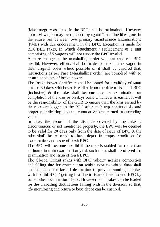
266
Rake integrity as listed in the BPC shall be maintained. However up to 04 wagon may be replaced by ‘good –examined’ wagons in the entire run between two primary maintenance Examinations (PME) with due endorsement in the BPC. Exception is made for BLC/BLL rakes, in which detachment / replacement of a unit comprising of 5 wagons will not render the BPC invalid. A mere change in the marshalling order will not render a BPC invalid. However, efforts shall be made to marshal the wagon in their original order where possible or it shall be ensured that, instructions as per Para (Marshalling order) are complied with to ensure adequacy of brake power. The Brake Power Certificate shall be issued for a validity of 6000 kms or 30 days whichever is earlier from the date of issue of BPC (inclusive) & the rake shall become due for examination on completion of the kms or on days basis whichever is earlier. It will be the responsibility of the GDR to ensure that, the kms earned by the rake are logged in the BPC after each trip continuously and properly, indicating also the cumulative kms earned in ascending value. In case, the record of the distance covered by the rake is discontinuous or not mentioned properly, the BPC will be deemed to be valid for 20 days only from the date of issue of BPC & the rake shall be returned to base depot in empty condition for examination and issue of fresh BPC. The BPC will become invalid if the rake is stabled for more than 24 hours in train examination yard, such rakes shall be offered for examination and issue of fresh BPC. The Closed Circuit rakes with BPC validity nearing completion and falling due for examination within next two-three days shall not be loaded for far off destination to prevent running of rakes with invalid BPC / getting lost due to issue of end to end BPC by some other examination depot. However, such rakes can be loaded for the unloading destinations falling with in the division, so that, it’s monitoring and return to base depot can be ensured.

267
Post loading / unloading examination by C&W staff is discontinued for all type of stock with a valid BPC except for the rakes/wagons loaded with steel consignment and container wagons. However, post loading / unloading check will be carried out by Guard and Driver as per proforma enclosed as annexure - I & II for all other trains. Non compliance of the instructions for GDR check shall be viewed seriously as it is safely related and staff violating the instructions shall be taken up suitably. To avoid shifting of consignments on running trains, Post loading check of all trains that are loaded with steel consignments should be carried out by C & W staff. In case the loading point is not a Train Examination point, necessary C&W staff should be deputed for checking and certifying proper lashing / securing of steel consignments. No intermediate examination of the CC rake by C & W staff is required after loading / unloading except for the unloading of wagons done by tippling operation. After tippling, the rake will be subjected to post-tippling examinations. In case, less than three rakes are being tippled per day, the check may be carried out by Guard and Driver as stated above. In case three or more trains are being tippled, post tippling check will be done by skeleton C&W staff. Any detachment / attachment of wagons/s at outstation shall be promptly entered and endorsed by SM /GDR in the Brake Power Certificate, indicating clearly the reasons for the detachment /attachment, station and date and append their signatures. The rakes going down the Ghat between CLR – QLM section in UBL division and SKLR-SBHR section in MYS division will however be offered at CLR & SKLR respectively for checking adequacy and up gradation of Brake Power by C&W staff along with other conditions / rules stipulated as per the special instructions for working of trains in these Ghat section. A minimum of 90% Brake power must be ensured. An endorsement should be made in the BPC to this effect.

268
7.3.1.2 OPERATION OF “BOXN CLOSED CIRCUIT RAKES “WITH INVALID BPC DUE FOR EXAMINATION: PROCEDURE FOR REVALIDATION OF BPC
With change in pattern of freight train operations on Indian Railway, there has been a substantial increase in dissipation / loss of CC rakes. Rly Board, has reviewed the procedure for maintenance & operation of Closed Circuit BOXN rakes. The relevant instructions applicable for operation of CC rakes belonging to SWR and other affiliated zonal Railways i.e. SR & SCR are given below- 7.3.1.2.1 In order to prevent loss/dissipation of CC rakes and at
the same time maintain standard of safety, it has been decided to introduce following system for BOXN CC rakes for limited depots only. The basic features of this system are as under:
The system will apply to a group BOXN CC depot serving a particular origin destination flow. Whenever rake of any depot of this group will become due for its next examination, on certain specify foreign railways, and if the rake is in empty condition, the BPC of such rakes may be revalidated by JE/SE/SSE (C&W) once, after intensive examination at the nearest train examination point for one trip (maximum 7 days from date of such examination or date of expiry of Original BPC, whichever is earlier) for loading to specified destinations and onward movement as empty to base CC depot. Such rake will not lose their CC character if returned back to their base CC depot, with in the extended validity of BPC. Once such a rake is unloaded at destination, it will be routed back to the original base depot. In order to maintain integrity of CC rakes, during intensive examination for revalidation of BPC as mentioned above, as far as possible, wagons due for ROH/IOH and unloadable wagons provided such wagons are safe for movement , shall not be

269
detached at outstation depots and efforts will be made to attend maximum possible repairs in yard itself. To ensure that the rakes are returned back to the original base depot, these rakes will move as “ FLYING RAKES” even in loaded condition so that, identification is made easy. For example, if a TNPM CC rake is over due in SWR and is loaded for HOM, the rake will be named and moved as “FLYING HOM”. The “FLYING HOM” rake after release at HOM will be sent back to TNPM in empty condition. 7.3.1.2.2 In order to enhance availability and prevent
dissipation of closed circuit rakes of BOXN following circuit applicable to SWR, SR & SCR has been identified
Circuit CC base Circuit-3 HPT, GY ,RDM, BZA, TNPM, JTJ 7.3.1.2.3 Detailed instructions for operation and maintenance of
closed circuit rakes in the identified circuit (for SWR, SR & SCR rakes)
Base Depot/Railway
Location of Overdue rake
Location for which loading is permitted after revalidation
SR
One trip to Bellary Power House and JSW siding in SWR or Muddanur TPS/Raichur TPS/destination in Bellary-Renugunta section of SCR
HPT/SWR
SCR One trip of Bellary Power House and JSW siding in SWR
TNPM, JTJ/SR SWR,SCR One trip to all destinations on SR only via destinations in GTL

270
division
GY/SCR SR One trip to Muddanur TPS/Raichur TPS/destinations in Bellary-Renugunta section of SCR
SR All destinations on secunderabad (SC) & Vijayawada (BZA) Divisions only
RDM/SCR
SWR
All destinations on Secunderabad (SC) and Vijayawada (BZA) Divisions via destinations in GTL division only.
7.3.1.2.4 Special conditions for maintenance and operational
discipline for the above circuits: CC rakes formed from off ROH/POH wagons based for maintenance on CC pattern at nominated base shall be operated over the ZRs defined in the circuit only mentioned on the BPC Provision of following facilities is a must at the nominated point. Proper computerized record keeping and documentation at CC base depot shall be ensured to monitor health/condition of CC rakes operating under this scheme including reliability, utilization, loss of rakes and integrity etc. Outstation depots, after intensive examination and revalidation of BPC for one trip (Maximum 7 days from date of such examination or date of expiry of original BPC, whichever is earlier) for specified destinations (as applicable) will make sure to transmit details of repairs attended, deferred repairs, attachment, detachment, unloadable, incoming brake power etc. to the CC base depot through email for condition monitoring and corrective actions as may be necessary at the base depot to ensure safety and reliability of train operation. Necessary facilities for email and training to staff/supervisors, wherever necessary, should be provided in DRM‘s power at the earliest.

271
FOIS terminal to be provided with C&W control, Sr.DME/C&W, CRSE (frt) and Head Quarters C&W control and at CC base depot & outstation depot of the railways served by above circuits. Rakes operating on ZRs not mentioned on the BPC will lose their CC character and will be treated as per instructions prevailing for normal end to end rakes. All rakes will be returned back to their nominated base CC depot as per validity of BPC. The BPC of such CC rakes shall be valid for 7500 kms/35 days or 6000 kms/30 days (whichever is earlier) according to the depot nominated for issue of such BPC validity the BPC shall be valid on the ZRs defined in the circuit. Incase kms are not logged on BPC, the validity of BPC should be treated as per the Railway Boards instruction for Premium end to end rakes. Infrastructure facilities at the nominated CC points shall be made available at par with ‘A’ category Depots. DRM should ensure that proper lighting arrangement, material handling equipments, welding facilities etc. are made available in these yards, if required by hiring so that quality of examination /repairs and safety is not compromised. In empty condition –In case BPC of the CC rake becomes invalid or nears invalidity at outstation in the specified circuit, it can be intensively examined by JE/SE/SSE(C&W) at the nearest point and BPC may be revalidated once at the outstation depot (within the circuit) for one trip (maximum 7 days from date of such examination or date of expiry of original BPC , whichever is earlier) as mentioned in table above, so that it can move to its nominated CC base for examination and issue of fresh BPC on CC base. Thereafter, the rake should be returned back to its nominated CC base depot for examination and issue of fresh BPC on CC pattern, otherwise it will lose CC character and treated as normal rake. In loaded condition – In case BPC becomes invalid at outstation in the circuit, it will be examined at the next available train examination point in the direction of movement and BPC shall be

272
revalidated for movement in the specified circuit up to its nominated depot via unloading point. Examination in the loaded condition should be in exceptional circumstances. In case of examination and revalidation of a rake at other than its nominated mother CC base, it is essential that in case of sick marking, the examination point have to try for in repair and as far as possible also replenish the sick wagon. After revalidation of BPC as per above, loading /unloading in such rakes will be confined to the destinations mentioned in table above. Else, the rake shall lose its CC character and will be logged in FOIS. The rake should be given a unique nomenclature. These nomenclature rakes should be entered in FOIS and monitored, including breaking/loss of CC rakes. Terminal equipments and connectivity for FOIS terminals, as specified above should be provided under extant powers of GM/DRM. Besides special conditions mentioned herein above with respect to maintenance and operation of these special CC rakes, all other general instructions regarding maintenance of air braked freight stock and 7500/6000 km CC rakes, issued by Board from time to time shall be observed.
7.3.1.3 MONITORING OF CC RAKES:
In order to have effective check/control, close monitoring of these CC rakes at Division and Zonal Head Quarter level is essential for which following guide lines are issued for strict compliance by all concerned The Chief Traffic Controller and C&W controller of the division should keep close watch on day-to-day basis on movement of the rakes CC rakes with invalid BPC shall normally not be permitted to run in service. However, deviations within the purview of Board’s instructions can be permitted in exceptional cases.

273
The kms earned by the rake as logged in the BPC should be relayed to the Chief Traffic Controller of the Division by the Traffic/Commercial staff at each loading/unloading station. The kms earned by the rakes shall also be nominated through FOIS and crosschecked. It shall be the responsibility of the Chief Traffic Controller of the Division to ensure that, the rakes are returned to the base depot for Primary Maintenance in empty condition before the expiry of BPC either on kms or days basis whichever is earlier. The movement of rakes shall be monitored closely at Zonal HQ level, in liaison with division control and through FOIS by CHC,C&W control , TI/HQ and ATM (Freight). As far as possible the rake shall be moved in defined circuit only as mentioned in Table ‘Á’. Any deviation in the pattern of movement shall be brought to the notice of Sr.DOM & Sr.DME (C&W) and necessary message should be given to the concerned for close follow up and return of the rake. However, CFTM & CRSE may permit change in route/circuit in case of exigencies. The rakes shall bear clear-stenciled mark of respective nomenclature with Base depot and divisions. The rakes shall be blocked by their respective nomenclature as ‘RR-1, CONSTAR-2 etc, either by suffixing or prefixing to the train no. during their movement for easy identification. The station/Yard staff, both commercial and operating at the loading/unloading points shall always check the nomenclature of the rakes stenciled on wagons on arrival at their station, So that, the same is ensured at the time of dispatch of Empty/Loaded rakes and the control is informed accordingly. Any failure in this respect shall be viewed seriously and the concerned staff shall be taken up fixing the responsibility. Frequent surprise checks should be conducted by the inspector of traffic and mechanical department to ensure that staff concerned is scrupulously following the instructions laid down. No CC rakes shall be dissipated, disintegrated or dissolved without the specific approval of CFTM and CRSE.

274
Only BOXN rakes with invalid BPC of the nominated depots either on Kms basis or on days basis shall be dealt with as indicated above, for all other type of CC rakes when detected with invalid BPC following procedure should be followed. For other Railway CC rakes running on SWR, as and when the BPC becomes invalid either on Km basis or days and the rake is in Empty condition, it shall be pushed to the nearest nominated Train Examination point for safe to run (STR) examination and endorsement on BPC by JE/SE (C&W) that the train is safe to run up to the base depot. One trip loading/unloading may be permitted if required for destinations Enroute to the base depot. Any other CC excluding the BOXN CC rakes of nominated depots as stated above, either of SWR or of any other railway running with invalid BPC, when detected in loaded condition, shall be subjected to GDR check and pushed to destination. After unloading, the empty rake shall be offered to the nearest nominated Train Examination point for STR examination and endorsement on BPC by JE/SE (C&W) that the train is safe to run upto the base depot. Such rakes with invalid BPC that are potentially unsafe, shall be moved on GDR check from the point of detection to the nearest nominated Train Examination point.
7.3.1.4 PREMIUM END TO END EXAMINATION
Premium end to end rakes will be formed out of nominated air brake stock only (all type of BOXN, BCN & BTPN). Premium End to End rakes will be intensively examined in ‘EMPTY’ condition and certified by examination points nominated as per Table ‘B’. Any alteration /addition in the nomination of depot/type of stock will be advised as and when required. If any of the condition, i.e. examination in empty condition or examination at nominated points is not satisfied; rake will not be certified as premium end to end rake and will operate as normal end to end rake.

275
Brake Power Certificate issued for such premium end to end rakes will be valid for 12 days from the date of issue. During this 12 days period, the rakes will be allowed multiple loading/unloading. After each loading and unloading, the rake will be examined by Guard and Driver before commencement of journey and observations will be recorded under the relevant columns of the Brake Power Certificate. In case of mechanized loading/unloading examination by TXR will be desirable. Stipulation to form rakes out of off POH/ROH wagons as is applicable for CC rakes will not apply in case of Premium end to end rakes. However, the rakes shall be turned out with minimum of 95% brake power by examining depot. After lapse of 12 days, the rake should be offered for next intensive examination at the first examination point in the direction of movement. To avoid examination in loaded condition, a grace period of 3 days will be permitted. However, after expiry of the grace period, i.e. after lapse of 15 days after issue of BPC, even a loaded premium rake shall be offered for examination at the first Train Examination point in the direction of movement. Further, in no case, Premium end to end rake shall be offered or loading through bypass routes or through yards which are not nominated for examination. After examination, the rake will be certified as premium rake subject to fulfillment of above mentioned conditions otherwise as conventional end to end rake. Movement of Premium end to end rakes will be monitored through FOIS by Traffic and Mechanical departments. The BPC for Premium rakes shall be issued in prescribed format only, printed on good quality green colour paper. The conditions governing validity of BPC and the check list for GDR check have been made part of the BPC (copy enclosed) and shall be applicable in general and followed by all concerned.

276
7.3.1.5 INTENSIVE (END-TO-END) EXAMINATION FOR VACCUM BRAKE AND AIR BRAKE RAKES (NON-CC)
Intensive (End-To-End) examination has been introduced for Vacuum and Air brake stock. Following instructions shall be applicable in common for both type of stock- Normally, ‘EMPTY’ rakes shall be offered in full formation for intensive examination and repairs and issue of Brake Power Certificate except when back loading of the rake has to be done at stations/sidings. Thereafter the empties shall be moved to the loading stations as per requirement of traffic. The BPC shall be prepared in prescribed format printed on a good quality green paper for air brake stock and pink paper for vacuum brake stock, in triplicate, one copy to be issued to Driver, one to Guard and third copy to be retained as record copy by issuing depot. The JE/SE/SSE (C&W) should enter individual wagon numbers in the BPC starting from the engine end, for ensuring the sanctity of rake. The time taken for examination and issue of BPC will be 3 to 4 hours. Due POH/ROH wagons identified during the examination shall be detached and moved to the nominated POH shop / ROH Depot as per the joint instructions in force. 7.3.1.5.1 END-TO-END Running of Vacuum brake (UIC)
stock: UIC stock will be permitted to run on End-to-End basis with following conditions- The rake should be intensively examined in ‘Empty’ condition except when back loading of the rake has to be done at stations/sidings. After such intensive examination, the rake should be moved in empty condition to the loading station as per requirement of traffic.

277
The BPC of the empty rake may not have the destination mentioned. At Train Examination point, the JE/SE/SSE (C&W) should write “Up to loading point & further to Unloading point” on the BPC. After loading the empty rake, the operating staff (Commercial staff if operating staff is not posted at that station/siding) will ensure that, the destination of the loaded train is clearly mentioned on the BPC and the same BPC will then become valid up to such destination. No driver should move the loaded train from the loading point unless the destination is clearly mentioned on the BPC. BPC of the loaded train without destination will be considered ‘INVALID’ and such train should be moved on GDR check & offered for examination at the first C&W point for examination and issue of BPC in the direction of movement. The empty rake must reach the loading point within 4 days of the issue of BPC including the day of issue, for the loaded rake to move on the same BPC. Otherwise, the rake (Empty or loaded) will have to be offered for examination for issue of fresh BPC at the ‘first nominated’ freight train examination point in the direction movement. At the destination after unloading, the rake must be examined once again in the empty condition and the above cycle repeats. In absence of freight train examination facilities at the loading point, the empty rake/back loaded rake must be examined at the first freight train examination point in the direction movement. The movement of empty rake/back loaded rake from the unloading point will be permitted after GDR checks as prescribed vide annexure ‘I’. It is important to note that, this check has been introduced to take care of an eventually that rake, which is to be offered for examination after completion of the loading and unloading cycle is required to travel for another 400 kms max. only before hitting the first Train Examination point in the direction of the movement. Examination due should not be avoided by taking the trains

278
through bypass routes or through yards which are not nominated for examination. It may be noted that, if a train unloaded at one point is required to be taken to another point for loading, then the train should not be taken to that loading point over shooting a Train Examination point, if such point falls enroute. The train must be got examined & BPC issued at that Train Examination point before taken to the loading point. 7.3.1.5.2 END-TO-END RUNNING OF AIR BRAKE STOCK: All the conditions mentioned for End-to-End Running of vacuum stock shall apply for End-to-End Running of Air brake stock also except the 4 days limit for reaching the loading point will only not apply to air brake stock. 7.3.1.5.3 BACK LOADING OF TRAINS: When back loading is done at a station where freight train examination facilities exist, the loaded rake should be examined at that station only and BPC issued. In cases, where back loading is done at a non Train Examination, such trains will be: Checked by the Guard and Driver as per the laid down procedure as Annexure I & II & allowed to run on Driver and Guard’s memo only up to the first nominated freight examination point in direction of movement. 7.3.1.5.4 BRAKE POWER CERTIFICATE: The Brake Power Certificate issued for End-to-End running of trains will be considered invalid if- The integrity of the rake is disturbed by more than 4 wagons in eight wheelers or 10 wagons in four wheelers except for BLC/BLL rakes in which detachment/replacement of a unit of 5 wagons is permitted. The rake is stabled for more than 24 Hrs. at Originating station where BPC was issued or at any enroute yard/station having freight

279
train examination facilities. The rakes, shall, then be required to be offered for examination and issue of fresh BPC. The destination is not mentioned in the BPC of a loaded train. The destination is mentioned in the BPC of any empty examination train. After each loading/unloading, the rake is not subjected to GDR check as per the instructions. The empty examined rake does not reach the loading point within 4 days of BPC including the date of issue of BPC (For vacuum brake stock only). 7.3.1.5.5 RULES GOVERNING VALIDITY OF ORIGINAL
BPC FOR TWO POINT BCN (PREMIUM) RAKES 1. On arrival of the rake at the first destination/common point, the SM/YM shall endorse on BPC and VG, the time and date of arrival of the rake at the station. 2. The SM/YM of the station where splitting is to be done, should relay the information of the rake such as the details of the rake, different destination for unloading/loading. BPC details etc. to the Divisional Operating Control (Chief Controller/Deputy Chief Controller) who, in turn shall inform the same to C&W Control of the division. Both the control officials should then jointly authorize movement of the rake in two parts as is required as per the unloading or loading programme between the stations concerned and back to a common point through numbered messages. The message number would then be written by the SM concerned on the original BPC under his seal and signature. 3. The part rake would be moved to the respective unloading / loading points and from then to a common point with Brake vans on GDR check duly following the procedure laid down vide annexure ‘I’. 4. Original BPC and VG shall be carried by the GDR of one of the formation. The SM/YM at the unloading/loading point shall, on arrival of the rake record the time and date of arrival on the BPC &

280
VG and keep them in safe custody to be handed over to the outgoing GDR after unloading/loading. 5. At respective unloading/loading points, traffic department shall ensure that, the load is properly secured against rolling or pilferage/damage to wagon or their parts. 6. Operating/Commercial staff at the unloading points will also ensure that, the operating handle of Load/Empty device is kept in ‘Empty’ before commencement of the unloading to prevent brake binding. 7. After release, the part rakes shall be moved to the common point on GDR check. The date and time of departure along with the remarks with respect to GDR check shall be recorded by GDR for part rake carrying original BPC/VG. 8. On arrival at the common point, both the portions shall be clubbed together ensuring that the consistency of the rake is maintained with position of the wagons in the same marshalling order as per the original VG. 9 Further movement/use of the rake shall then be on original BPC subject to all other conditions governing its validity. However, to ensure that there are no damages to the wagons during shunting at the common point, GDR check as per the annexure ‘I’ shall be carried out and record the same in the original BPC before further movement of the rake. 7.3.1.5.6 BRAKE POWER: The minimum Originating Brake Power for rakes running on end to end pattern will be 85% and 90% for Vacuum and Air brake stock respectively. 7.3.1.5.7 CLEARANCE OF STABLED LOADS FROM A
NON-TXR STATION: In case of clearance of stabled loads from Way-side stations where C&W staff is not available, the Guard and Driver shall follow instructions contained in Board’s letter No.2000/ Safety

281
(A&R)/19/35 dtd.31.7.01, the procedure for which is given vide Annexure ‘l’ &ll. 7.3.1.5.8 Post Loading/Unloading/Tripping Examination: Post loading/Unloading examination by C&W staff may be discontinued except for rakes loaded with steel consignments, containers & post tippling where C&W staff is provided for the same. However, post loading/unloading/tippling check will be carried out by Guard and Driver as per the check list enclosed vide Annexure ‘l’ & ‘ll’ where C&W staff is not provided/ specified. 7.3.1.5.9 RAKE COMPOSITION: It will be responsibility of the Station Master/Yard Master to ensure that, full loads of the prescribed composition for respective stock are offered for examination. The rakes should not be offered in piece meal for examination but should be offered only when the rake is formed fully and ready for dispatch with the available composition. It shall be the responsibility of the SM/YM of the station/yard to ensure the rake integrity after loading/unloading is maintained at the time of despatch unless warranted due to detachment of wagons due to defects, which may endanger safety to train. The SM/YM/Chief Goods Supervisors shall also be responsible to ensure that, the handles of Empty/load device are set in correct position in Empty/Load as the case may be. They shall also be responsible for ensuring at unloading point, that, the handles of the loaded rake are placed on ‘EMPTY’ before commencement of Unloading of wagons. The plain bearing stock/plain bearing stock mixed with roller bearing stock in a train (such as in four wheeler tank wagons) shall be subjected to examination every 800 kms. However, a plain bearing B/van attached to UIC stock shall be certified on End-to-End pattern.
282
The pattern of examination and certification of Departmental stock as given in Table ‘D’ shall be followed. 7.3.1.5.10 Marshalling Order To obtain effective brake power on goods trains, the following marshalling order shall be ensured Next to the engine, a minimum of two braked wagons with brakes and brake cylinders in working order shall be attached. In side the rear brake van, a minimum of two braked wagons with brakes and brake cylinders in working order shall be attached. All other wagons shall be marshaled in any order subject to the provision that, not more than 2 Inoperative/piped wagons are coupled together on train. Grouping of the piped wagons shall be done subject to the provision that for every group of one or more piped wagons marshaled together, an equal number of braked wagons are marshaled in front and rear of such wagons.

283
ANNEXURE ‘I’ IMPORTANT INSTRUCTIONS FOR GUARD, DRIVER AND STATION STAFF: It is primary responsibility of the Guard (being in charge of the train) as well as Driver and stations staff for not allowing train running on invalid BPC in violation of the existing instructions. In case, Guard and Driver notice that BPC is invalid, it should be brought to the notice of station staff and the train has to be offered for examination at the same station (if it is a train Examination point) or at the first TXR point in the direction of movement after carrying out GDR check. At each loading/ unloading point before starting the train, Driver, Guard and station staff shall ensure that, the BPC is valid and follow the instructions as per Rly. Board’s Letter No.200/safety (A&R)/ 19/35 of 31.7.2001. Items to be checked by GDR are given below GDRCHECKLIST: Items to be checked by Guard and Drivers: 1. Rake integrity is not disturbed by more than 4VUs (8 W-
wagons) & 5 VUs for BLC/BLL: Only intensively examined wagons given fitness by Train Examining staff are attached. (10 wagons in case of 4 wheeler wagons)
2 All CBCs and Air Hoses are properly coupled and locked. 3 All the Angle Cocks are in open condition. 4 The rear most Angle Cock of the last wagon is closed
condition. 5 Empty/load device handle is in proper position. 6 There is no loose fittings/hanging parts like springs push-pull
rod, Brake Beam, Safety brackets, Brake blocks etc. which may endanger safe running of the train.
7 Hand Brakes are released. 8 Doors of wagons are closed and locked/secured.

284
9 Any other abnormally noticed and necessary action taken. Special attention should be given to axle box cover plate, pull rod, Control Rod, SAB, Hand brake wheel rod, Hand brake connecting lever, Lever
10 Guard and Driver shall prepare a memo jointly on a plain sheet in triplicate indicating the brake power and deficiency if any in the proforma given below and append their signatures. Guard should then obtain SM/YM’s endorsement on two copies of the joint memo and handover the third copy for SM/YM’s record. SM/YM will inform the Section Control after making the endorsement of the joint memo and obtain clearance for the train to move.
11 Check & confirm of requisite brake pipe pressure & continuity through VHF/Whistle code before starting the train.
12 The Driver should conduct ‘brake feel’ test at the first available opportunity and satisfy himself about the adequacy of brake power and safety of train.

285
ANNEXURE II Proforma for Joint Check by the Driver and Guard: 1 Date 2 Train No. & Loco No. 3 Time. Locomotive Attached 4 Checked from (time) To-- 5 BPC NO, Date & Station & whether valid 6 BP Pressure In Loco & B/Van 7 %age Brake power available (No. of
operative cyl/Total No. of cyl.x100%)
8 Loaded/Unloaded/Tippled at 9 Total Load 10 Any attachment/detachment Signature of Driver Signature of Guard Driver’s Name & HQ….. Guards name & HQ…… Signature of SM/YM Station: Note: About one hour time may be required to carry out a proper GDR check. Hence the booking of GDR may be planned accordingly.

286
ANNEXUR-III Procedure for the GDR check Check the BP hoses of Loco and train formation is properly coupled and their Angle cocks are in open position. Check validity of the available BPC. Create 5.0 kg/cm2 pressure in the BP system. After 5.0 kg/cm2 BP is created in Loco, the driver will inform the Guard through Walkie-talkie or by some means and the Guard will proceed towards the Loco by cross checking the wagon numbers tallying them with the vehicle guidance and BPC. On arrival of the Guard at Loco, the Guard on one side and the Driver on the other side of the formation will proceed towards brake van for checking the following items. BP hoses between the wagons are properly coupled and their Angle cocks are opened except the rear end of Last vehicle. The isolation cocks of all the DVs are in service position. CBCs are properly closed and their Operating handles are not lifted and the locks are seating properly. Check for any loose fitting/hanging parts like push-pull rod, Brake Beam, Safety brackets, Brake blocks etc, which may endanger safe running of the train. Check the Hand brakes are released. Check for the Load/Empty in proper position ie. On indicator plate the handle is in yellow colour on left side for Empty and black colour on right side for Loaded. Check for any brake blocks jam and if any release the same. Confirm the BP gauge is coupled in Guards Brake van. The Guard after confirming sufficient level of BP, (ie. 4.8 kg/cm2 for up to 56 vehicles and 4.7 kg/cm2 for more than 56 vehicles) is available as shown in the Gauge provided in B/V, will destroy the pressure for 30 seconds and confirm that the brakes are getting applied in first four wagons from BV. He will then counter sign in the back side of the BPC for the continuity of BP in the train.

287
Driver and guard will then prepare a memo jointly on a plain paper as per Annexure‘ll’ and follow the procedure prescribed. Driver and Guard will check continuity of the Brake pipe pressure and confirm through VHF/Whistle code. Driver will back his train with a little jerk for two or three wagon length for locking the lifted CBC lock pieces if any, in accordance with Guards guidance for the space in rear of his Brake van. The Driver will back the brake power of his train at the first opportunity, and regulate the speed of the train accordingly. 7.3.1.5.11 7.3.1.5.12 PATTERN OF TRAIN EXAMINATION ON
S.W.RLY Table ‘B’: Non-Closed Circuit (Premium End-To-End) Rakes Divn Examination
Point Feeding Stations/Sidings on S.W.Rly
UBL HPT BAY, JVSL, HPT, BYC, KBL, GDG
SGT WFD, ICD, DBU, DPJ SBC BYPL TK, DRU, KJM, YNK, BYPL, DKN HRR HRR, RNR, HVR, DVG, CTA,
DRU MYS
MNGT MNGT, HAS

Table ‘A’: Closed Circuit Rakes Divn Base
Depot Rake Nomenclature
Stock Zones of Operation
Circuit of Operation
Validity of BPC
RR BOXN Over SWR,SCR, SR & KRCL/ C.Rly (only ROHA/ PEN)
Loading & Unloading points
BOXNHA Over SWR only Loading & Unloading points over SWR
6000 kms/30 days whichever is earlier
UBL HPT
DDS BOXN Over SWR, SCR, SR (PNMB only), & KRCL/ C.Rly (only ROHA/ PEN)
Loading & Unloading points
6000 kms/30 days whichever is earlier
SBC SGT/ ICD/ WFD
CONSTAR BLC/ BLL
SWR, SR, SCR, NR
SGT(WFD)-TKD-HOM-MVTS-SNF-CHTS SGT(WFD)
6000 kms/30 days whichever is earlier.
CRSE/SWR CFTM/SWR

7.4 CASNUB BOGIES
The CASNUB bogie consists of two cast steel side frames and a floating bolster. The bolster is supported by a group of coil springs. The bolster is also incorporated with a load proportional friction damping arrangement by means of snubbers. The side frames are connected at the bottom by a mild steel spring plank to maintain the squareness of bogie frames
CASNUB bogie is provided with secondary suspension only and no primary suspension is available. The Secondary suspension is given between floating bolster and the side frame by means of a group of coil springs.

290
7.4.1 Types of CASNUB Bogies
Following are the different types of CASNUB bogies: 1) CASNUB 22W 2) CASNUB 22WR 3) CASNUB 22WM 4) CASNUB 22NL 5) CASNUB 22NLM 6) CASNUB22NLB 7) CASNUB 22HS 8) CASNUB NLC (25TON A/L) W=Wide Jaw; R=Retrofitted; M =Modified; N =Narrow Jaw; L=Light weight; B=Belly shaped bolster; HS=High Speed
7.4.1.1 IMPORTANT COMPONENTS OF CASNUB BOGIES:
Side frames with friction plates and brake wear plates, Bolster with wear liners, Spring plank, fitted by means of bolts & rivets, Load bearing springs and snubber springs, Friction shoe wedges, Centre pivot arrangement comprising of Centre pivot top, Centre pivot Bottom, Centre pivot pin, Centre pivot retainer & locking arrangement, Side Bearers, Elastomeric Pad, Wheel set with Cartridge Bearing, Axle Box / adapter, retainer bolt & side frame key assembly, Bogie Brake Gear, Brake Beam
7.4.2 The salient features of CASNUB bogies:
Sl. No Features Description
1. Gauge 1676 mm
2. Axle load Axle capacity is 22.9 t, the axle load of the wagon is based on the No. of springs in the nest.

291
3. Wheel diameter
1000 mm (New) 956 mm (New) for CASNUB 22 WR 906 mm (cond) for all types
4. Wheel base 2000 + 5mm
5. Type of Axle bearing
Standard AAR Tapered Cartridge Bearing Class E suitable for 144.5 x 277.8 mm journal. This bearing consists of two rows of bearings one at front and another at rear. Each row is provided with 24 numbers of tapered rollers.
6.
Distance between journal centres
2260 mm
7. Distance between side bearers
1474 mm
8. Type of side bearers
CASNUB 22W Roller Type (Clearance Type) Retrofitted CASNUB 22W, CASNUB 22W(M), 22NL, 22NLB Constant contact type (Metal bonded rubber pad, housed inside side bearer housing) CASNUB 22HS Spring loaded side bearer. (All the side bearers will be converted to PU pads type in near future – Type A & B)
9. Type of pivot
CASNUB 22W - IRS Type Top- RDSO Drg. No. W/BE-601 Bottom – RDSO Drg. No. W/BE-602 or similar mating profile integrally cast with bolster. CASNUB 22W(M), 22NL, 22NLB, 22 HS Spherical Type to RDSO Drg. No. WD-85079-S/2

292
10. Pivot Pin
Head less pin for CASNUB 22 W, WR Castle nut pin for CASNUB 22WM Shackle type with 173mm height for CASNUB 22NL,WM Shackle type with 149mm height for CASNUB 22 NLM,NLB&HS
11. Anti rotation features
Anti rotation lugs have been provided between bogie bolster and side frame
12. Type of brake beam
CASNUB 22W, 22NL, 22NLB, 22 HS: Unit type fabricated brake beam supported and guided in the brake beam pockets. CASNUB 22W(M) : Unit Type Cast Steel brake Beam suspended by hangers from side frame brackets.
13. Suspension details Long travel helical spring
14. Elastomeric pads
On all types of bogies except CASNUB 22W.
14. Speed limit 90 Kmph for all types except CASNUB 22 HS which is 100 Kmph
7.4.2.1 CASNUB 22W WERE CONVERTED TO 22WR BY RETROFITMENT OF THE FOLLOWING;
Elastomeric pad to the thickness of 45mm were introduced between side frame and adaptor The maximum wheel dia is restricted to 956mm. Modified adaptor with reduced height of 129.5 mm is provided instead of 152.5 mm height.
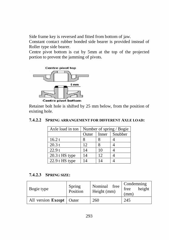
293
Side frame key is reversed and fitted from bottom of jaw. Constant contact rubber bonded side bearer is provided instead of Roller type side bearer. Centre pivot bottom is cut by 5mm at the top of the projected portion to prevent the jamming of pivots.
Retainer bolt hole is shifted by 25 mm below, from the position of existing hole.
7.4.2.2 SPRING ARRANGEMENT FOR DIFFERENT AXLE LOAD:
Axle load in ton Number of spring / Bogie Outer Inner Snubber 16.2 t 8 8 4 20.3 t 12 8 4 22.9 t 14 10 4 20.3 t HS type 14 12 4 22.9 t HS type 14 14 4
7.4.2.3 SPRING SIZE:
Bogie type Spring Position
Nominal free Height (mm)
Condemning free height (mm)
All version Except Outer 260 245

294
Inner 262 247 CASNUB 22 HS
Snubber 294 279 Outer 260 245 Inner 243 228 CASNUB 22HS
Snubber 293 278 Note: The grouping of spring should be paired within a difference of 3mm in free heights
7.4.2.4 IMPORTANT CLEARANCES:
Types of CASNUMB Bogie Description 22W&
22WR 22W (M)
22NL & NLB
22 HS
Lateral clearance Between Side frame & Bolster 18 18 18 25
Lateral clearance Between Side frame & Adapter 25 25 16 16
Longitudinal clearance Between Side frame & Adapter
2 10 9 9
Longitudinal clearance Between Side frame & Bolster
6 6 6 6
Clearance between Anti rotation lug and Bolster 4 4 4 4
7.4.2.5 WEAR LIMITS;
Item Std Cond Wear limit
Bolster pocket 35 deg on slope
Bolster liner 8 3 5

295
Bolster land surface 444 438 3 Rotation stop lug 518 512 3 Bolster column Gib (outer) 234/241 244/251 5 Bolster column Gib (inner) 136 146 5 Friction shoe wedge block vertical surface from centre line of spigot
61 54 7
Slope surface (by gauge) 3 Centre Pivot bottom vertical side (CASNUB 22W)
5.5
Centre Pivot bottom vertical side (other types)
4
Centre Pivot bottom seat wear (for all types)
4
Elastomeric pads 46 42 Constant Contact Rubber pad for side bearer
114 109
Reject the pad for any crack more than 50mm. Reject the pad when bond failures giving way of 40 mm in any direction. Adapter Thrust shoulder 0.7 mm Adapter Crown lugs 4.0 mm Adapter crown seat 3.5 mm Adapter side lugs 3.0 mm Adapter sides 3.0 mm Side frame column friction plate 4.0 mm Side frame column sides 5.0 mm Side frame anti rotation lug 3.0 mm Pedestal crown roof 5.0 mm Pedestal crown sides 4.0 mm Pedestal sides 2.0 mm Pedestal jaw 4.0 mm

296
7.4.2.6 BUFFER HEIGHT ADJUSTMENT:
Use 12 mm packing when wheel diameter reaches below the sizes as mentioned below. It should be provided between EM pad and Adaptor. 22W 848 mm 22W(R) 910 mm 22W (M) 954 mm NL/HS 954 mm Use 37 mm packing when wheel diameter reaches below the sizes as mentioned below. It should be provided between EM pad and side frame. 22W 924 mm 22W (M) 930 mm NL/HS 930 mm Note: 37 mm packing is not required for 22(W) R. Manual adjustment of brake rigging based on wheel diameter is required as follows: Hole position Wheel diameter A 1000 – 982 B 981 – 963 C 962 – 944 D 943 – 925 E 924 - 906 Pop marks on the side frames: The wheelbase of CASNUB bogie is 2000+/-5mm. Though there is a variation of 10mm between maximum and minimum (1995 mm &2005mm) in wheelbase, while pairing the side frames during assembly, they are to be paired within a difference of 2mm in wheelbase so as to keep the wheels in alignment with the bogie. To

297
facilitate the pairing of side frames within the difference of 2 mm in wheelbase the button heads are given on the side frames.
The wheel base and the number of button heads should remain on the side frames are given below
Wheel base Number of button heads Above 1995 and up to 1997 One
Above 1997 and up to 1999 Two
Above 1999 and up to 2001 Three
Above 2001and up to 2003 Four
Above 2003 and up to 2005 Five The modifications done on Air brakes wagons with CASNUB bogie: 1. The striker casting wearing plate is modified and secured by means of bolts and nuts with the striker casting to prevent working out of wearing plates on run.

298
2. A stopper is welded at an angle of 20º with the vertical on the air hose carrier suspension bracket, to prevent the excessive displacement of air hose carrier on run. This modification prevents damages to the air hoses.
3. Metallic bushes are used in the brake rigging instead of nylon bushes, to prevent frequent replacement of bushes. 4. Bulb cotters are used instead of split cotters. 5. Worn wheel profile is adopted for wheels. 6. Truss beams are strengthened near brake heads by welding three numbers of MS strips to the length of 215 mm to prevent the truss beams from getting crack near the brake heads.
7. Bogie push rods are provided with safety straps on either ends to prevent the dropping of truss beams on run, whenever the pins are working out. A bolt is fitted with the floating lever to keep the bogie push rod in position, in case the pin fails.

299
8. Load empty horizontal lever support bracket is strengthened at the joint with the body by welding gusset plates at the joint.
9. An anti rotation lug is welded between the sleeve nut and screw rod of empty tie rod to prevent the tampering.
10. Control rod diameter of SAB is increased from 28 mm to 32 mm, to prevent the control rod from getting bent.
11. An additional support bracket is given for supporting the SAB pull rod to prevent malfunctioning of SAB enroute.

300
12. DV isolating handles have been standardised to have two positions only.
Vertical – Working. Horizontal – Isolated. 13. The centre pivots are secured by means of rivets, to prevent the trolleys from getting shifted. 14. Quick couplings are used in the brake van, to facilitate easy fitment and removal of pressure gauges. 15. For Casnub 22 W retrofitted bogie, the centre pivot bottom is cut by 5 mm at the top of the projected portion, to prevent the jamming of pivots.

301
7.5 BLC WAGONS
7.5.1 Introduction:
Bogie Low platform flat wagons for carrying ISO containers.
Different sizes of containers:
BFKI wagons were used for movement of containers. When ISO containers, with more height than the inland containers is loaded on the BFKI wagons, the overall dimensions exceeds the Standard moving dimensions of X – class engine by 254 mm at the top side. And the load is to be moved as ODC with speed restrictions. This in turn affects the speedy movement of containers.
Description Length Breadth Height ISO Containers inland 20 feet 2438 mm 2593 mm (8’-6”) ISO containers international 20 feet 2438 mm 2896 mm(9’-6”)
ISO containers for international 40 feet 2438 mm 2896 mm(9’-6”)

302
If the same containers are loaded on the specially made well wagons, the load can very well be moved as Non-ODC, but at either ends of the wagon 1.5 metres of length are necessary to accommodate the CBC couplers. Consequently the length of the wagon is increased by 3 metres (3000 mm). This will inturn reduce the number of wagons on a loop line from 42 for the existing BFKI wagons to 38 resulting in loss of earning capacity.
So to over come the above two shortcomings, the BLC wagons are developed with a intention to move the ISO containers as non-ODC load with high speed as well as with more number of wagons for a given length of formation. These wagons are manufactured in multiple units with low floor height at the centre to accommodate the ISO containers and raised at ends to facilitate coupling of these unit with the Loco and brake van. The wagon which is having raised at one end is called A-Car and the wagon which is not having raised end is called B-Car. Each
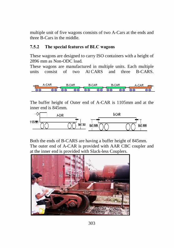
303
multiple unit of five wagons consists of two A-Cars at the ends and three B-Cars in the middle.
7.5.2 The special features of BLC wagons
These wagons are designed to carry ISO containers with a height of 2896 mm as Non-ODC load. These wagons are manufactured in multiple units. Each multiple units consist of two A–CARS and three B-CARS.
The buffer height of Outer end of A-CAR is 1105mm and at the inner end is 845mm.
Both the ends of B-CARS are having a buffer height of 845mm. The outer end of A-CAR is provided with AAR CBC coupler and at the inner end is provided with Slack-less Couplers.

304
Both the ends of B-Cars are provided with Slack less coupler. The overall slack in Slack less couplers between the two wagons is only 1 ½”, When compared to a slack of 7 ½” in the standard AAR CBCs between the two wagons. The maximum permissible wheel diameter for both the wagons is 840 mm. The condemning diameter is 780 mm. These wagons are provided with two-stage load sensing device, which admits a maximum pressure of 2.2 kg/cm2 when the gross load is less than 40 tons, and 3.8 kg/cm2 when the gross load exceeds 40 tons automatically. These wagons are provided with CASNUB LCCF20 (C) bogies. The spring loaded side bearers are used on these bogies. The spring loaded side bearers are designed to take 90% of load in tare condition. These wagons are provided with automatic twist locks. These locks are designed to lock the containers with the wagons with a force of 600 kgs. It unlocks the container from the wagon with a force of 1000 kgs.
The floor height of these wagons from the rail level is decreased to 1009 mm from the standard of 1269 mm. The maximum permissible speed is 100 KMPH. A formation can be formed with

305
9 multiple units with 45 wagons. The length of each unit is 69 metres approximately. These wagons are provided with new hybrid design of bogie frame and bolster in order to bring down the plat form height.
7.5.2.1 THE SPECIAL FEATURES ADOPTED IN THE SUSPENSION OF BLC WAGONS
These wagons are provided with two stage vertical suspension for providing softer suspension under tare and stiffer suspension under load condition. The two stage vertical suspension is necessary to provide higher static deflection in empty condition, so that the spring off-loading in the empty condition lies within limits. Vertical suspension in loaded condition is stiffer on account of the constraint in the space between the bolster and the bogie frame.
The softer suspension is provided between the body and bolster and the stiffer suspension is provided between the bolster and bogie frame.

306
7.5.2.2 COMPARISON OF 22 NLB & CONTAINER BOGIE TYPE LCCF 20 (C)
Description 22 NLB LCCF 20 (C) Centre pivot height from Rail level
932 mm 715 mm
Max height of side frame from Rail level
851 mm 786 mm
Bottom of side frame 165 mm 149 mm Height of side bearer top
921 mm 772 mm
Wheel diameter 1000/906 mm 840/780 mm Side frame design Cast steel design for
narrow jaw adapter Cast steel design for wide jaw adapter
Bolster design Separate center pivot Integral center pivot
Side bearer CC pad Coil spring Load bearing coil spring
12 outer, 8 inner spring
14 outer, 12 inner spring
Snubber springs 4 Nos, IS: 3195 Gr.60 Si 7
4 Nos, IS 3195 Gr.50 CrMoV4
Brake shoe Conventional Non metallic Adapter Narrow jaw Wide jaw Elastomeric pad Similar Similar Side frame key Similar Similar Spring plank Similar Similar

307
7.5.2.3 7.5.2.4
7.5.2.5 SLACK FREE/LESS COUPLERS
We know that the buffer height of A-Car at raised end is 1105 mm and for the B-Car is 845 mm. Due to the difference in buffer heights between the raised end of A-Car and the B-Car, the draft force transmission not lies on the same line. Because of the eccentricity in the draft force line between these wagons, there is a possibility for off loading of wheel when ever the tractive force/buffing force is applied suddenly.
Centre pivot Integral Flat type
Centre pivot riveted to Bolster

308
This sudden load is mainly caused by the excessive slack available in the standard AAR couplers. The shock loads acting on couplers can be prevented by reducing the slack between the two couplers.
To overcome the above shortcoming, the Slack less/free couplers are introduced for the BLC wagons at one end of A-Car and at both ends of B-Cars.
Description AAR CBC Slack free coupler Draft Gear travel of first wagon
3 ¼ Inches ¾ Inches
Draft Gear travel of adjacent wagon
3 ¼ Inches ¾ Inches
Slack between the two knuckles
1 Inch No Knuckles. Straight draw bar is provided
Total Slack 7 ½ Inches 1 ½ Inches

309
Different parts of Slack free couplers are Key stone Mini draft gear, Straight draw bar, Standard AAR yoke, Striker casting.
7.5.3 Comparison between the BLC and BFKI type wagons.
Sl. No
Features BLC BFKI
01 Wagon unit Consists of 5 Wagons. (2 Nos of A-Car and 3 Nos of B-Cars.)
Single Wagon.
02 Platform height 1009 mm 1269 mm 03 Length of wagon
over head stock A-Car - 13625 mm B-Car - 12212 mm
13716 mm
04 Tare weight A-Car - 19.25 tons B-Car - 18.50 tons
20.5 tons
05 Pay load 61 tons 48 tons 06 Wheel diameter Max - 840 mm
Cond - 780 mm Max - 1000 mm Cond- 906 mm
07 Permissible speed 100 Kmph 75 Kmph 08 Coupler CBC and Slack less
draw bar CBC
09 Empty load device
Two stage automatic Pneumatically operated
Manually operated.
10 Suspension Two stage suspension
Single suspension
11 Lock for locking containers
Automatic Twist Lock
Manual Retractable Anchorage Locks
12 No. of wagons per Rake
45 Wagons 42 Wagons
310
7.5.4 Attentions to be paid for these wagons during the Examination
All under gear items including brake gear, draw & buffing gear and running gear should be examined and kept in sound condition. Wheels must be tapped to detect Loose/Cracked wheel. The wheel profile checked visually and in the case of doubt to be checked with Tyre defect gauge for the rejectable defects. Maintain Control A dimension to 72 +0 / – 2 mm. Maintain the brake power to 100%. The general conditions of under frame, bogies with load sensing device, side bearer assembly should be examined and repairs attended. Check all the safety fittings, safety brackets etc, and defects if any should be attended. Check the hand brake for its proper functioning. Maintain a clearance of 21 mm within a tolerance of ±1 mm between load sensing device and the stopper. Check all the automatic locks mounted on under frame for its proper working condition and inspect for any welding failure of mounting brackets.
7.6 SAB AND LOAD EMPTY BOX
7.6.1 SAB (SVENSKA AKTIE BOLAGOT BROMS Regulator)
This is a mechanical device provided in the brake rigging, and forms part of the pull rod, for automatic adjustment of the clearance between the brake blocks and wheels in the brake rigging. This automatically operates to shorten or lengthen the length of the pull rod, to adjust the excess or less slack in the brake rigging or brake block clearance. This helps to maintain the clearance between the brake block and the wheels to a pre-determined constant value always, thereby maintaining the piston stroke of the brake cylinder constant. This, in turn, always maintains constant brake power for the wagon or coach on the run.

311
7.6.1.1 TYPES OF SAB
DRV 450 DRV 600 Code Expansion Remarks D Double
acting It increases or decreases the length of the pull rod automatically to maintain a constant piston stroke/clearance.
R Rapid It is fast in adjusting the piston stroke/clearance. It takes a maximum of only two brake applications and release for adjusting the piston stroke/clearance.
V Verificative It always verifies the piston stroke/clearance with control A dimension for the purpose of automatic adjustment of piston stroke/clearance.
450/600 This is the capacity of SAB up to which the length of the SAB pull rod can be increased or decreased. It is 450 mm for Coaching stock and 600 mm for Goods stock.
7.6.1.2 MAIN PARTS OF THE SAB
1. Adjuster Spindle 2. Leader Nut 3. Adjuster Nut 4. Traction sleeve 5. Barrel 6. Adjuster Tube
7. Barrel Spring 8. Clutch spring 9. Take up Spring 10. Pay out Spring 11. Adjuster Ear 12. Control Rod Head 13. Control rod
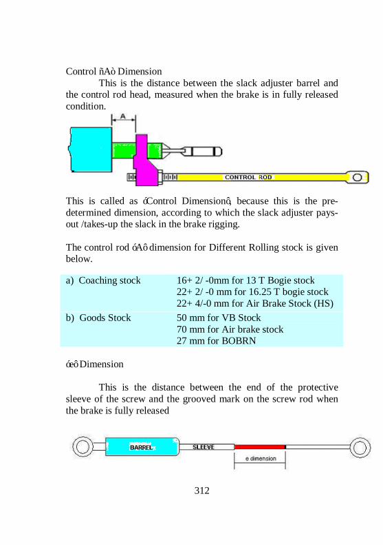
312
Control “A” Dimension This is the distance between the slack adjuster barrel and the control rod head, measured when the brake is in fully released condition.
This is called as ‘Control Dimension’, because this is the pre-determined dimension, according to which the slack adjuster pays-out /takes-up the slack in the brake rigging. The control rod ‘A’ dimension for Different Rolling stock is given below.
‘e’ Dimension This is the distance between the end of the protective sleeve of the screw and the grooved mark on the screw rod when the brake is fully released
a) Coaching stock 16+ 2/ -0mm for 13 T Bogie stock 22+ 2/ -0 mm for 16.25 T bogie stock 22+ 4/-0 mm for Air Brake Stock (HS)
b) Goods Stock 50 mm for VB Stock 70 mm for Air brake stock 27 mm for BOBRN

313
This indicates the total capacity of the slack adjuster available for the adjustment of the brake rigging clearance. This dimension will be 375±25 mm for coaching stock and 555±20 mm for goods stock. it will decrease as wear takes place on brake blocks, wheels, brake gear pins and bushes due to brake applications. And it will be the maximum when all Brake blocks, brake gear pins and bushes are new and all the wheels are at maximum diameter. As the ‘e’ dimension decreases and reaches to the minimum due to the wear on the wheel tread, which cannot be made up (worn out brake blocks, brake gear pins and bushes can be replaced with new ones), manual adjustment shall be done according to the worn out wheel diameter, on the adjusting link of the bogie. This will ensure that sufficient capacity of ‘e’ dimension will be again made available for subsequent adjustments. Functioning of the SAB: The SAB is working based on the principle of LIMITING FRICTION. Due to this Limiting friction, the nuts that are provided inside the SAB gets rotated automatically, whenever the excessive forces offered due to the incorrect slack acting on them. The rotation of these nuts on the screw rod causes the screw rod to move inward or outward for increasing or decreasing the length of pull rod till the correct adjustment of piston stroke and clearance is obtained.
7.6.1.3 ADJUSTMENT OF CONTROL ‘A’ DIMENSION
Assemble the slack adjuster (SAB brake regulator) on the bogie brake rigging. Ensure that the hand brake and brake cylinders and the rigging are in fully released condition and in proper working order. Apply and release the brakes few times and again ensure that the brake rigging is in fully released condition. Check the ‘A’ dimension, if found correct, secure the pins correctly.

314
If found more, disconnect the control rod from its bracket and lengthen it by rotating anti-clockwise.
If found less, shorten its length by rotating it clock-wise.
One full rotation of the control rod will alter the ‘A’ dimension by 2 mm. Fix the control rod in its bracket and apply and release the brakes few times, check ‘A’ dimension, adjust it if required and test. Secure the pin when correct. ‘A’ Dimension to be correctly set to maintain the correct piston stroke and in turn the correct brake power. Rotating the SAB or slack adjuster barrel will not alter the ‘A’ dimension. Once set correctly shall not alter it during service.
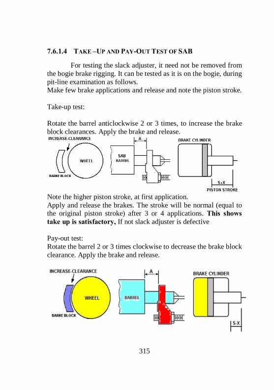
315
7.6.1.4 TAKE –UP AND PAY-OUT TEST OF SAB
For testing the slack adjuster, it need not be removed from the bogie brake rigging. It can be tested as it is on the bogie, during pit-line examination as follows. Make few brake applications and release and note the piston stroke. Take-up test: Rotate the barrel anticlockwise 2 or 3 times, to increase the brake block clearances. Apply the brake and release.
Note the higher piston stroke, at first application. Apply and release the brakes. The stroke will be normal (equal to the original piston stroke) after 3 or 4 applications. This shows take up is satisfactory, If not slack adjuster is defective Pay-out test: Rotate the barrel 2 or 3 times clockwise to decrease the brake block clearance. Apply the brake and release.

316
Note the short piston stroke at the first application. The stroke will be normal (equal to the original piston stroke) after 3 or 4 applications. This shows Pay-out is satisfactory. If not the slack adjuster (SAB) is defective.
7.6.2 Empty-Load Device
It is a mechanical device, which enables to provide two different leverage ratios to the brake rigging of the wagon for the empty and the loaded conditions
The braking force required to stop a train within the permissible stopping distance depends on the load of the train. As the load increases, more brake power is required, and as the load decreases, less brake power is required to stop the train. So the brake power should be increased or decreased according to the requirement by changing the brake leverage ratio. To enable this, the ‘EMPTY-LOAD BOX’ device is provided on wagons, in between the brake cylinder and the brake blocks in the brake rigging.

317
The position of the change over lever of the E/L Box is to be set to ensure correct brake power according to the gross weight, as given below. Less than 42.5 tonnes – in empty position 42.5 tonnes &above - in loaded position Brake The LOAD-EMPTY device consists of two horizontal levers (one live and the other dead) and are connected by means of empty and load tie rods. When the handle is kept in empty position, the empty tie rod is connected with the system and in turn provides low leverage ratio, thereby gives lesser brake force. When the handle is kept in load position, the load tie rod is connected with the system and in turn provides higher leverage ratio, there by gives higher brake force as required.
7.6.2.1 RESETTING OF EMPTY/LOAD BOX:
Release brake rigging completely, including the release of hand brake fully. Ensure horizontal levers can move freely. Keep change over lever in ‘load’ position. Shift lock nuts and washers of sleeve nut as far as possible.
Rotate sleeve nut and tighten empty tie rod fully.
Then rotate sleeve nut slowly in reverse direction to lengthen empty tie-rod. Stop rotating as soon as the end of the “live horizontal lever” starts moving.
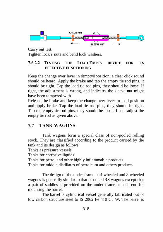
318
Carry out test. Tighten lock – nuts and bend lock washers.
7.6.2.2 TESTING THE LOAD-EMPTY DEVICE FOR ITS EFFECTIVE FUNCTIONING
Keep the change over lever in ‘empty’ position, a clear click sound should be heard. Apply the brake and tap the empty tie rod pins, it should be tight. Tap the load tie rod pins, they should be loose. If tight, the adjustment is wrong, and indicates the sleeve nut might have been tampered with. Release the brake and keep the change over lever in load position and apply brake. Tap the load tie rod pins, they should be tight. Tap the empty tie rod pins, they should be loose. If not adjust the empty tie rod as given above.
7.7 TANK WAGONS
Tank wagons form a special class of non-pooled rolling stock. They are classified according to the product carried by the tank and its design as follows: Tanks as pressure vessels Tanks for corrosive liquids Tanks for petrol and other highly inflammable products Tanks for middle distillates of petroleum and others products. The design of the under frame of 4 wheeled and 8 wheeled wagons is generally similar to that of other IRS wagons except that a pair of saddles is provided on the under frame at each end for mounting the barrel. The barrel is cylindrical vessel generally fabricated out of low carbon structure steel to IS 2062 Fe 410 Cu W. The barrel is

319
placed longitudinally on the under frame and secured by means of rivets to the saddle. The saddle is welded on under frame at each end.
7.7.1.1 CODES USED FOR DIFFERENT TYPES OF TANK WAGONS
Sl. No
Type of wagon Code for the wagon
1 Ammonia tank TAL, BTAL, BTALN 2 Chlorine tank LCT 3 Liquefied petroleum gas tank TLGL, BTPGL, BTPGLN 4 Sulphuric acid tank TSA & MBTSA 5 Petrol tank TPR/A, MBTPX & MBTPZ 6 Oil tank TORX 7 Heavy oil tank TORX 8 Bitumen tank TBT 9 Coal tar tank TR 10 Petrol tank TR & MBTP 11 Oil tank TO 12 Oil tank MBTOX 13 Caustic soda tank TCS, BTCS 14 Hydrochloric acid tank THA 15 Molasses tank TM & MBTM
7.7.1.2

Various types of barrel mountings, safety fittings and their functions: Sl. No Mounting/Fittings Functions
1 Safety valve
The safety valve is provided to prevent building up of excess pressure inside the barrel. It is fitted on the barrel either on the diaphragm plate inside the dome or on a separate opening on the barrel. This is provided on tanks for highly inflammable liquids such as petrol, Aviation sprit etc.
2 Relief valve It is a spring-loaded valve fitted on the barrel of tanks for corrosive liquids. Its main function is to release built up pressure, if it exceeds the working pressure limit.
3 Safety vent
This consists of frangible disc (lead or any approved material not affected by lading), which ruptures at specified pressure. It is an additional safety fitting to safeguard against the failure of the relief valve. When the built up pressure exceeds the working pressure of the relief valve and the latter fails to function for any reason the frangible disc of this safety vent ruptures to release the pressure.
4 Compressed air valve
It is provided on tank from which the contents are unloaded by compressed air. Its main function is to control the rate of discharge by controlling the rate of air admission.
5 Vapour extractor cock
Its function is to extract vapour from the tank while filling

321
6 Master valve It is a gravity discharge valve fitted with a hand wheel in the dome for manual operation.
7 Bottom discharge valve
BG 4-Wheeler Bottom discharge valve are provided with single bottom discharge valve situated underneath the master valve while on BG/MG eight wheeler stock two bottom discharge valves are fitted, one on either side and connected with the master valve through a “T” pipe. The main function of the valve is to control the flow of the contents and also to serve as an additional safety stop in case the master valve fails or breaks. The bottom discharge valve openings are also provided with blank flanges to be used with 2 mm compressed asbestos fibre jointing material to serve as further check on accidental leakage of contents.

The periodicity of POH is given below: Sl. No Type of wagons For Ist POH For subsequent
POH
1 4 wheeler tank wagons except those listed below 4 years 3-1/2 years
2 Tanks for liquid chlorine and hydro chloric acid 2 years 2 years
3 Tanks for liquid ammonia 2-1/2 years 2-1/2 years 4 Tanks for petroleum gas 4 years 4 years 5 BTPN 6 years 6 years The codal life of tank wagons is 45 years.
7.7.1.3 STEAM CLEANING FOR PRESSURE VESSELS, PETROLEUM AND OTHER HIGHLY INFLAMMABLE PRODUCTS:
Tanks as pressure vessels, tanks for petroleum, other highly inflammable products, vegetable oils, bitumen, coal tar and molasses are cleaned by steam. The tanks requiring steam cleaning should be placed as near the steam supply line as possible and protected against any movement. The berthing siding should be completely isolated from all other traffic. In case of pressure vessels, it should be ensured that all the gas has been discharged to the atmosphere. After ensuring that the tank barrel is no longer under pressure, the following sequence should be followed: Remove the manhole cover together with manhole housing, valves etc. and leave the tank exposed to atmosphere for 24 hours. Entry of staff in the tank barrel should be strictly prohibited and signs with suitable legends displayed at a reasonable distances away from the tanks to be steam cleaned. Insert pipe through manhole and steam the interior of barrel for 12 hours. In order that the tank

323
barrel is thoroughly steamed from inside, the steam pipe should be provided with a “T” connection at its lower end and so directed as to blow steam towards both ends. Remove condensed steam collected in the tank barrel and keep the barrel exposed to atmosphere for another 24 hours. The following are the tests that should be conducted to ensure the tanks are free from contamination gases of the contents. AMMONIA TANK BARREL Fill the tank barrel with water. Collect a specimen of the water in a clean glass bottle. Test the specimen of the water with red litmus paper. If the colour of the litmus paper turns into blue, it indicates that the barrel is still having the gases of ammonia and requires steam cleaning. NESSLER’S TEST Test the specimen of the water with a mixture of potassium mercuric iodide and potassium hydroxide. If the colour of the mixture turns into brown, it indicates that the barrel is still having the gases of ammonia and requires steam cleaning CHLORINE TANK WAGONS Fill the tank barrel with water. Collect a specimen of the water in a clean glass bottle. Test the specimen of the water with red litmus paper. If there is any bleaching effect on the litmus paper, it indicates that the barrel is still having the gases of chlorine and requires steam cleaning. LPG TANK WAGONS Fill fresh water in a clean bottle. A string is to be attached to the bottom of the bottle. Lower the bottle through the manhole up to the bottom of the tank and tilt the bottle. Allow the water to flow out and let the gas get into the bottle. Wait for 5 minutes and lift the bottle and close the mouth immediately after withdrawing.

324
Take it away from the tank. Bring a lighted matchstick near the mouth of the bottle after opening it. If there is no flame it is free from injurious gas. But in case it gives out a flame, the tank should again be steam cleaned again.
7.7.1.4 PROCEDURE FOR STEAM CLEANING OF BITUMEN AND MOLASSES TANK WAGONS:
Close the manhole cover and open bottom discharge valve. Pass steam through the air inlet valve for sufficient time till the bitumen melts and drains away through the water discharge valve. The bitumen should be collected in containers and not drained out on the floor. Open the manhole cover to see whether the tank is completely cleaned from inside. In case any residue is left behind the above procedure should be repeated. Remove heating arrangement i.e., heating pipe, internal pipe, etc, from the tank. Clean inside surface of the heating pipe by scrapping the carbon layer with wire brush or other suitable process. Blow in air under pressure from one end. The outer surface of the heating pipe should be cleaned with kerosene oil.
7.7.1.5 PROCEDURE FOR CLEANING OF TANKS FOR CORROSIVE LIQUIDS:
HYDROCHLORIC ACID TANKS: Open the manhole and the washout cover and start cleaning the barrel with water. Initially the water coming out of the washout opening will show excessive acidity, which will turn blue litmus paper into red. The washing should be continued till blue litmus paper shows no change. Then close the wash out cover, fill the tank with water. Collect a sample of the water in a bottle. Test the sample of water with blue litmus paper. If the colour is changing to red, it indicates that the tank is still having traces of acid and requires cleaning. SULPHURIC ACID TANKS:

325
Wash the Sulphuric acid tank barrels with ½ % to 1% solution of sodium phosphate commercial or half percent solution of soda ash so as to neutralize the sulphuric acid. The washing should be done as soon as it is received in workshops. Since concentrated sulphuric acid absorbs moisture when left open to moist air, the acid will be diluted with time. It is to be remembered that diluted sulphuric acid is highly corrosive and attacks the tank barrel more vigorously. Collect a sample of water in a bottle. Test with blue litmus paper. If the colour of the paper changes into red, it indicates that tank is having still traces of acid and requires cleaning again. After cleaning allow the tank for drying. Caution: As addition of water to sulphuric acid will produce intense heat, resulting in splashing of steam, the solution of commercial sodium phosphate should be added or spread gradually and with care. CAUSTIC SODA TANKS: Wash the barrels with hot water. Freedom from alkalinity can be easily ascertained by litmus test (if red Litmus changes to blue, there are still traces of alkalinity). After it is free from alkalinity, water should be drained and barrel dried before inspection and repairs
7.7.1.6 CHECKS TO BE CARRIED OUT BY THE C&W ENGINEERS BEFORE THE TANK WAGON IS CERTIFIED FOR LOADING
Master Valve: Leakage of master valve should be checked while keeping the bottom discharged valve in open. Bottom discharge Valve: Proper functioning and fluid tightness of the bottom discharge Valve should be ensured. Blank flange: The blank flange of the correct thickness made out of steel plate and with a gasket of proper material between the blank flange and bottom discharge valve flange should be tightened by six bolts and nuts.

326
Tank barrel: Tanks with cracks on barrels should be marked sick. Leaky Tank barrels: The leakage of tank barrels may be caused due to the following reasons. Mechanical injury to the valve face and /or valve seat as a result of foreign material, particularly nuts and bolts finding their way inside the tank wagon, valves seat not properly secured to the stool by proper interference fits and malfunctioning of master valve.
7.7.1.7 PRECAUTIONS IN THE CASE OF LEAKAGE FROM THE LOADED TANK WAGONS:
CHLORINE & AMMONIA tanks; Chlorine and ammonia gases are poisonous and have a characteristic pungent odour, which gives warning of their presence in the atmosphere before dangerous concentrations are attained. In the case of chlorine, the greenish yellow colour of the gas makes it visible when high concentrations are present. In the case of ammonia, if sufficient concentration of the gas is present in the atmosphere, it will irritate the eyes and the respiratory system. As such, in the event of leakage, all present in the vicinity should be warned to keep on the windward side of the tank. HIGHLY INFLAMMABLE GAS tanks; All the flames or fires near it should be extinguished or removed. Smoking should not be allowed. Spectators should be kept away. Only battery operated torches or incandescent electric lights with gas proof sockets should be used. Oil lanterns or signal lamps used for signalling must be kept away. The steam engine available if any should be moved away from the site. The leaky tank wagon should be removed as quickly as possible to an open area, where the escaping gas will be less hazardous. Earth should be spread over any surface on which the LPG has leaked out in liquid form. Call the company concerned for further attention.

327
8 BRAKE POWER CALCULATIONS
8.1 Bogie mounted AC Coach:
Technical Data: 1. Diameter of the cylinder = 20.3cm (8”) 2. Area of piston (A) = 323.65 Cm2 3. Maximum BC pressure (B) = 3.8 kg/Cm2 4. Leverage ratio of levers (C) = 366:174 5. No. of levers per axle (D) = 2 6. No. of brake blocks (N) = 16 7. Cylinder efficiency (CE) = 0.9 8. Rigging efficiency (RE) = 0.9 9. Tare weight of the coach = 50 Tonnes Force available on the piston = (A) X (B)
(F) = 323.65 X 3.8 = 1230 kg = 1.23 t
Mechanical advantage/axle = (C) X (D)
(MA) = (366/174) x 2 = 4.2
Theoretical braking force available on an axle = (F) X (MA)
= 1.23 X 4.2 = 5.166 Tonnes
Theoretical braking force available on a coach
= 5.166 X 4 = 20.664 Tonnes
Theoretical braking force available on each brake block
(TF) = 20.664/16 = 1.3 Tonnes
Actual brake force on each brake block = (TF) X (CE) X (RE)
(AF) = 1.3 X 0.9 X 0.9 = 1.046 Tonnes
Actual brake force available on a coach = (AF) X (N)
= 1.046 X 16 = 16.736 Tonnes
% of braking-theoretical (Theoretical braking force available on a coach/Tare weight x100)
= (20.664/50) x 100 = 41.328 %
% of braking – actual (Actual brake force available on a coach/Tare weight x 100)
= (16.736/50) x 100 = 33.472 %

328
Summary: 1. Brake force available on each brake head = 1.046 Tonnes 2. Percentage of braking = 33.472 % Similarly brake power calculation for BMBC Non AC can be done with the following data; Technical Data’s 1. Diameter of the cylinder = 20.3cm (8”) 2. Area of piston (A) = 323.65 Cm2 3. Maximum BC pressure (B) = 3.8 kg/Cm2 4. Leverage ratio of levers (C) = 256:134 (1.91) 5. No. of levers per axle (D) = 2 6. No. of brake blocks (N) = 16 7. Cylinder efficiency (CE) = 0.9 8. Rigging efficiency (RE) = 0.9 9. Tare weight of the coach = 37.55 Tonnes

329
8.2 Underframe Mounted Brake System (Modified Horizontal lever) AC coach:
Technical Data; 1. Diameter of the cylinder 35.5 cm (14”) 2. Area of piston (A) 990 Cm2 3. Maximum BC pressure (B) 3.8 kg/Cm2 4. Leverage ratio of
Horizontal levers Mounted on Body (A) (C) 372:328
5. Leverage ratio of levers fitted on bogie (D) 245:178
6. No. of levers per Bogie (E) 4 7. No. of brake blocks (N) 16 8. Cylinder efficiency (CE) 0.9 9. Rigging efficiency (RE) 0.9 10. Tare weight of the coach 50 Tonnes

330
Brake Power Calculations: 1. Force available on the
piston = (A) X (B) (F) = 990 X 3.8
= 3762 kg (3.762 t) 2. Mechanical advantage per
Bogie = (C) X (D) X (E) (MA) =(372/328)x(245/178)x4
= 6.244 3. Theoretical braking force
available on a Bogie = (F) X (MA)
= 3.762 X 6.244 = 23.49 Tonnes
4. Theoretical braking force available on a coach
= 23.49 X 2 = 46.98 Tonnes
5. Theoretical braking force available on each brake block (TF)
= 46.98/16 = 2.936 Tonnes
6. Actual brake force on each brake Block/Brake Head = (TF) X (CE) X (RE) (AF)
= 2.936 X 0.9 X 0.9 = 2.378 Tonnes
7. Actual brake force available on a coach = (AF) X (N)
= 2.378 X 16 = 38.054 Tonnes
8.
Percentage of braking -theoretical (Theoretical braking force available on a coach / Tare weight of the Coach x 100)
= (46.98/50) X 100 = 94 %
9.
Percentage of braking –actual (Actual brake force available on a coach / Tare weight of the Coach x 100)
= (38.054/50) X 100 = 76.10 %
Summary: 1. Actual Brake force available on each brake head = 2.378 Tonnes 2. Percentage of braking – Actual = 76.1 % Similarly the brake power of (Modified H/L) Non- AC Coach can be calculated by taking the following Technical data;

331
Technical data; 1. Diameter of the cylinder 35.5 cm (14”) 2. Area of piston (A) 990 Cm2 3. Maximum BC pressure (B) 3.8 kg/Cm2 4. Leverage ratio of Horizontal levers
Mounted on Body (A) (C) 372:328(1.134) 5. Leverage ratio of levers fitted on
bogie (D) 200:200(1) 6. No. of levers per on a Bogie (E) 4 7. No. of brake blocks (N) 16 8. Cylinder efficiency (CE) 0.9 9. Rigging efficiency (RE) 0.9 10. Tare weight of the coach 37.55 Tonnes Similarly the brake power of under frame mounted (Non modified H/L) AC Coach can be calculated by taking the following Technical data; Technical Data’ 1. Diameter of the cylinder 35.5 cm (14”) 2. Area of piston (A) 990 Cm2 3. Maximum BC pressure (B) 3.8 kg/Cm2 4. Leverage ratio of Horizontal
levers Mounted on Body (A) (C) 420:280 (1.5) 5. Leverage ratio of levers fitted on
bogie (D) 245:178 (1.376) 6. No. of levers per on a Bogie (E) 4 7. No. of brake blocks (N) 16 8. Cylinder efficiency (CE) 0.9 9. Rigging efficiency (RE) 0.9 10. Tare weight of the coach 50 Tonnes Brake power calculations;

332
1. Force available on the piston = (A) X (B)
(F) = 990 X 3.8 = 3762 kg (3.762 t)
2. Mechanical advantage / Bogie = (C) X (D) X (E)
(MA) = (420/280)x(245/178)x4 = 8.258
3. Theoretical braking force available on a Bogie = (F) X (MA)
= 3.762 X 8.258 = 31.06 Tonnes
4. Theoretical braking force available on a coach
= 31.06 X 2 = 62.12 Tonnes
5. Theoretical braking force available on each brake block (TF)
= 62.12/16 = 3.88 Tonnes
6. Actual brake force on each brake Block/Brake Head = (TF) X (CE) X (RE) (AF)
= 3.88 X 0.9 X 0.9 = 3.154 Tonnes
7. Actual brake force available on a coach = (AF) X (N)
= 3.154 X 16 = 50.464 Tonnes
8. Percentage of braking -theoretical (Theoretical braking force available on a coach / Tare weight of the Coach x 100)
= (62.12/50) X 100 = 124 %
9. Percentage of braking –actual (Actual brake force available on a coach / Tare weight of the Coach x 100)
= (50.464 /50) X 100 = 100.92 %
Summary: 1. Actual Brake force available on each brake head 3.154 Tonnes 2. Percentage of braking – Actual 100.92 %

333
8.3 Percentage of Braking for the BCN Wagon
Brake force available on piston:- Diameter of cylinder = 35.5 cm Area of piston = π×35.52 / 4
= 990 cm2 Max brake cylinder pressure (= Max BC pr x Area of piston)
= 3.8 Kg/cm2
Force available on the piston = 3.8 x 990 = 3762 Kgs
Total leverage Ratio in Empty: Leverage ratio of Horizontal lever in empty 335/620 = 0.54 Leverage ratio of floating lever (since truss beams are fitted at the centre of the floating lever the leverage ratio of floating lever becomes)
(356 + 178) / 178 = 3

334
Total No. of levers per bogie 2 Total leverage ratio per bogie (leverage ratio of horizontal levers in empty X leverage ratio of floating lever X No. of floating levers)
0.54 x 3 x 2 = 3.24
Total leverage ratio of wagon ( total leverage ratio of one bogie X 2)
3.24 x 2 = 6.48
Total theoretical brake force of a wagon in empty; Total theoretical brake force of a wagon in empty = (brake force on the piston X total leverage ratio of a wagon)
3762 x 6.48 = 24378 Kgs
Actual Brake force of a wagon in empty (theoretical brake force – loss due to SAB) x rigging efficiency
(24378 – (12x200)) x 0.9 = 19780 Kgs
Actual brake force available on each brake block (Actual brake force available on a wagon / No. of brake blocks)
19780 / 8 = 2472.5 Kgs
Total leverage Ratio in Load: Leverage ratio of Horizontal lever in Load 458/497 = 0.92 Leverage ratio of floating lever (since truss beams are fitted at the centre of the floating lever the leverage ratio of floating lever becomes)
(356 + 178) / 178 = 3
Total No. of levers per bogie 2 Total leverage ratio per bogie (leverage ratio of horizontal levers in load X leverage ratio of floating lever X No. of floating levers)
0.92 x 3 x 2 = 5.52
Total leverage ratio of wagon ( total leverage ratio of one bogie X 2)
5.52 x 2 = 611.04
Total theoretical brake force of a wagon in Load; Total theoretical brake force of a wagon in Load = (brake force on the piston X total leverage ratio of a wagon)
3762 x 11.04 = 41532 Kgs

335
Actual Brake force of a wagon in load = (theoretical brake force – loss due to SAB) x rigging efficiency
(42532 – (12x200)) x 0.9 = 35219 Kgs
Actual brake force available on each brake block (Actual brake force available on a wagon / No. of brake blocks)
35219 / 8 = 4402 Kgs
Percentage of Braking when the handle is in empty position at tare condition; Actual Brake force available on a wagon when the handle is in empty
= 19780 Kgs
Tare weight of wagon = 25.8 Tonnes = 25800 Kgs
Percentage of braking when the handle is in empty at tare condition =(actual brake force available on wagon in empty / tare weight of wagon)
19780 / 25800 = 76.6 %
Percentage of Braking when the handle is in empty at change over weight of 42.5 Tonnes = (Actual Brake force available on a wagon when the handle is in empty / change over weight)
19780 / 42500 = 46.5 %
Percentage of Braking when the handle is in load at change over weight of 42.5 Tonnes = (Actual brake force available on a wagon when the handle is in load / Change over weight)
35219 / 42500 = 82.8%
Percentage of Braking when the handle is in load at load of 80 Tonnes = (Actual brake force available on a wagon when the handle is in load / Gross weight of wagon)
35219 / 80000 = 44%

336
8.4 Brake force calculation by hand brake in SLR
Technical Data: Diameter of the H/B wheel 360 mm Lead of the Screw 19 mm Leverage Ratio of H/B & Screw (π x dia)/lead
(π x 360)/19 = 59.52

337
Leverage ratio of Bell crank 216:108 = 2 Leverage ratio of H/L No.4 (420+120)/120 = 4.5 Leverage ratio of H/L No.5 120/(120+270) =
0.307 Leverage ratio of H/L No.6 552/273 = 2.022 Leverage ratio of Floating lever 302/158 = 1.91 No.of floating levers 2 Force applied on the H/B wheel 25 Kg Efficiency 0.4 Brake force calculation: Total mechanical advantage Hand brake (leverage ratio of screw x leverage ratio of bell crank x leverage ratio of H/L No.4 x 5 x 6 x leverage ratio of floating levers x No.of floating levers)
59.52 x 2 x 4.5 x 0.307 x 2.02 x 1.91 x 2 = 1274
Theoretical brake force (force applied on H/B wheel x mechanical advantage of H/B)
25 x 1274 = 31850 Kgs
Actual braking force of H/B (Theoretical braking force x efficiency of H/B)
31850 x 0.4 = 12740 Kgs
Percentage of braking (Actual braking force / Tare weight)
(12740 / 40600) x 100 = 32%
Actual braking force on each brake head 12740 / 4 = 3185 Kgs

338

339
9 BRAKE POWER RULES
9.1 Brake power Certificate
Brake Power Certificate is a document prepared in triplicate by the C&W Engineer in the prescribed format and jointly signed by the C&W Engineer, Guard and driver of the train. The C&W engineer retains original copy and the duplicates are handed over to the driver and the Guard. Brake Power Certificate can be issued only after a thorough examination of the train and after testing the effectiveness of the brake power. Certification of Coaching stock shall be done as per Railway Board Policy Circular (RPC 4). Certification of Freight Trains shall be done as per the JPO/SWR No.2/2009 dated 12.11.2009 A qualified C&W Engineer is only the competent authority to issue the BPC. Any alteration in the BPC will make it invalid, however it can be valid when countersigned by the person issuing the BPC. Validity of the BPC cannot be extended. Speed restriction is imposed when the composition of a train consists of: 1. ISMD Load 2. Travelling Crane 3. Sick/Damaged vehicles Speed restriction, if any imposed should be endorsed at the top of the front page of the BPC and signed by the C&W Engineer.
9.1.1 Marshalling of the train:
9.1.1.1 COACHING STOCK:
Marshalling of the coaches is mainly done taking into consideration the safety of passengers during collisions.

340
In case of SLRs, which have passenger portion on one side and luggage cum brake portion on the other the SLR should be marshalled in such a way that the luggage and brake portion is trailing outermost in the rear or in front next to engine. If for any unavoidable reason the above is not possible, the passenger portion should be locked. In case of new design SLRs with passenger portion in the middle this can be positioned in any convenient way. Marshalling of 3 coaches in front of and in rear of SLR on short trains is permitted provided they have working brakes and subject to further condition that the two front most and rear most coaches are Anti telescopic. An inspection carriage may be attached as 4th trailing coach on such trains. This does not however apply to trains running mainlines/trunk routes. VPs, LRs, WLRRMs and other coaching vehicles which do not carry passengers may be marshalled as operationally convenient however as far as possible these should be preferably marshalled as outermost vehicles at either end to absorb the impact of collision energy. Inspection carriage whether anti telescopic/steel body or not and occupied by Railway officers may be marshalled as operationally convenient. However not more than one inspection carriage (occupied) shall be attached by mail/express trains at a time. (Rly Bd letter No. 88/coaching 01/34/2 Dtd: 16.06.2006) Reserved bogies occupied by passengers and inspection carriages/ saloons occupied by VIPs should be treated as any other passenger coach and marshalled accordingly Sectional/through service coaches if they are ant telescopic or steel bodied may be marshalled as operationally convenient. However whether feasible they should be marshalled inside the SLR. While determining the position of marshalling of sectional/ through service coaches the fact that these coaches will be attached/ detached enroute leaving the train service coaches exposed as outermost should be borne in mind and therefore the marshalling order of sectional/through service coaches and train service coaches decided in accordance with all the other instruction above.

341
In case of POH/Sick coaches which are returned to shops for major repairs and are attached to passenger train, such coaches should be properly locked and windows secured so as to prevent entry of any passenger into these coaches. In that case it is not necessary to attach these coaches according to safety marshalling instructions and can be attached next to the train engine or rearmost as convenient. If for any reason it is not possible to lock these coaches such coaches should be treated like other passenger coaches in the train formation and should therefore be marshalled inside the required no of anti telescopic/steel bodied coaches. If wagon is attached to the passenger trains for dealing parcel traffic, it should be attached next to engine if loaded beyond 20 tonnes. The wagon must be certified by a train examiner by like any other VPU or coaching stock, speed of the train to be restricted as per the permitted speed of wagon. Movement of one dead Dsl/Elec locomotive is permitted with mail/express/passenger train provided the brake power of mail/express/passenger train is 100 percent.
9.1.1.2 FREIGHT STOCK:
Single 4 wheeler is not to be marshalled between two bogies or between a bogie and an engine. This restriction will be applicable to a banker engine attached at the rear. While marshalling explosive wagons Max 10 wagons by goods trains and three wagons by mixed trains can be grouped together. Minimum support of three wagons containing non dangerous goods must be given from steam engine, brake van, passenger coaches and wagons containing dangerous goods. One support wagon is enough from Dsl/Elec loco. For liquified gas any number of wagons can be attached, two support wagon from engine, Brakevan and passenger carrying vehicle must be given.

342
Highly inflammable liquids like petrol, kerosene etc. one support wagon from Dsl/Elec loco and brake van should be attached. Three support from dangerous goods and two support wagons from compressed gas wagons should be attached. Damaged vehicle should be attached in rear of the rear most BV certified fit by C&W staff and C&W staff should accompany. Permitted only during day light hours. Crane should be certified fit by the crane supervisor. Dummy truck should be attached for resting the jib. While proceeding to accident spot should be attached next to engine. Livestock should be attached as far as away possible from the TE/banking engine. At least four bogies or seven unit support wagons should be given from all types of train engines. To obtain effective brake power on goods trains, the following marshalling order of the wagons shall be ensured. Next to the train engine a minimum of two braked wagons with brakes and brake cylinders in working order shall be attached. In front of the rear brake van a minimum of two braked wagons with brakes and brake cylinder in working order shall be attached. All other wagons shall be marshalled in any order subject to the provision that not more than 2 inoperative wagons are coupled together on trains. Grouping of the inoperative wagons shall be done subject to the provision that for every group of one or more inoperative wagons marshalled together, an equal number of braked wagons are marshalled in front and in rear of such wagons. In case of dead diesel/electric locomotive the vacuum/brake pipe shall be connected and the dead locomotive is to be treated as a inoperative vehicle and therefore at least 10 fully braked four wheeler units with effective brake cylinders shall be attached behind the dead locomotive.

343
A competent person not lower then an asst.driver shall accompany the dead locomotive. The dead locomotive brake shall be fully released. The brake pipe and the main reservoir pressure should be discharged or the vacuum fully destroyed. In case of diesel locomotive the MU2B valve shall be put in dead position 2” COC of VA1B valve (Banker COC) to be kept on closed position. GD 80D filter inlet to be covered and secured by a paper. COC of 28VB valve to be kept in close position. The dead locomotive shall be attached next to train locomotive where double heading is permitted. The total number of locomotives including the dead locomotive shall not exceed two. If the dead locomotive is not attached next to train engine, it shall be marshalled anywhere on the goods train, provided that the minimum distance between the dead locomotive and the train locomotive shall be equal or more than the largest span of the bridge in the section where the dead locomotive is to be hauled. In case of dead locomotive fitted with side coupling rods it shall be ensured that side coupling rods are in position.
9.1.2 Percentage of brake power for Originating trains
All coaching stock should be with 100% brake power from the originating station. On originating BG and MG vacuum goods trains, there shall be 85% and 80% effective brake power respectively, subject to observance of any higher limit prescribed by the Railways for particular Ghat/other sections. The minimum originating brake power for air braked goods trains, running on end-to-end pattern of examination, shall be 85% except wherever local instructions have specified higher level of brake power to meet specific requirement. Exception shall only be made after prior approval of Chief Rolling Stock Engineer has been obtained for each individual case.

344
Percentage of brake power for Premium End to End trains shall be 95% from the originating station. The originating brake power for air braked goods trains; running in close circuits shall be 100%.
9.1.2.1 PERCENTAGE OF BRAKE POWER FOR TRAINS’ EN-ROUTE:
When the driver experience difficulty in controlling the train and has reason to ask for a check on the adequacy of brake power, he shall contact control office. The section controller shall take the advice of the C&W controller and the Power controller in dealing with trains reported as having inadequate brake power. The controllers shall take into consideration the difficulty reported by the driver, proximity to a major station/yard, scope for moving the train, if necessary, at restricted speed, scope for moving train examination staff to the enroute station, blocking a line at the enroute station affecting through traffic etc. The decision shall depend on the circumstances of the case on hand. The driver and guard shall do check for the adequacy of brake power enroute. Depending on the circumstance, a loco inspector and a train examiner may be arranged to jointly check with the guard and driver. If in such enroute checking, the train is found to have a brake power percentage above 70% there is no need to take up brake power up gradation.
9.1.2.2 LEVEL OF AIR PRESSURE IN LOCOMOTIVE AND BRAKE VAN
Coaching stock should have the following pressure in Train Engine and Brakevan;
On locomotive In rear SLR BP 5.0 kg/ Cm2 4.8 kg/ Cm2

345
FP 6.0kg/ Cm2 5.8 kg/ Cm2 Minimum air pressure level of brake pipe in the air braked freight train in locomotive and brake van should be as follows.
No of wagons On locomotive On last wagon Up to 56 BOXN /40 BCN 5.0 kg/ Cm2 4.8 kg/ Cm2 Beyond 56 BOXN /40BCN 5.0kg/ Cm2 4.7 kg/ Cm2
Validity of the brake power certificate shall be as per RPC 4 for coaching stock and JPO for freight trains
9.1.2.3 TEST TO BE CARRIED OUT ON THE LOCO TO IDENTIFY THE PROBLEMS IF THE LOCOMOTIVES DO NOT CREATE SUFFICIENT VACUUM
Vacuum Locos; Blockage test: Remove one end of the vacuum hosepipe and raise it upwards. If more than 8cms vacuum is created, there is a blockage in the system. Repeat the procedure on the other end of the locomotive. Efficiency test: Diesel/electric locomotive shall be tested to ascertain that on 8 mm dia leak hole in 3 mm thick plate, with single exhauster working at slow speed on electric locomotive and with engine working at idle speed on diesel locomotive, the vacuum level should be 53 cm. In case of Diesel locomotive in the formation of 70 FWU or more, a 12 mm test plate shall be used and the loco shall create 45 cm of vacuum. The blockage and efficiency tests on diesel and electric locomotives shall be carried out not only before turning it out from the shed but also in the yard to rule out loco defects whenever the train is held up for creation of vacuum.
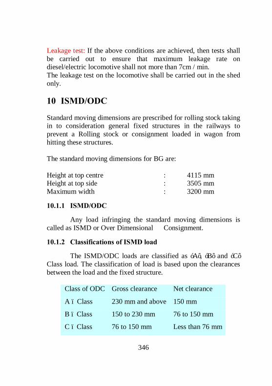
346
Leakage test: If the above conditions are achieved, then tests shall be carried out to ensure that maximum leakage rate on diesel/electric locomotive shall not more than 7cm / min. The leakage test on the locomotive shall be carried out in the shed only.
10 ISMD/ODC
Standard moving dimensions are prescribed for rolling stock taking in to consideration general fixed structures in the railways to prevent a Rolling stock or consignment loaded in wagon from hitting these structures. The standard moving dimensions for BG are: Height at top centre : 4115 mm Height at top side : 3505 mm Maximum width : 3200 mm
10.1.1 ISMD/ODC
Any load infringing the standard moving dimensions is called as ISMD or Over Dimensional Consignment.
10.1.2 Classifications of ISMD load
The ISMD/ODC loads are classified as ‘A’, ‘B’ and ‘C’ Class load. The classification of load is based upon the clearances between the load and the fixed structure.
Class of ODC Gross clearance Net clearance
A – Class 230 mm and above 150 mm
B – Class 150 to 230 mm 76 to 150 mm
C – Class 76 to 150 mm Less than 76 mm

347
Gross clearance is the clearance between the load and the fixed structure when the load is at rest. Net clearance is the clearance between the load and the fixed structure when the load is in motion. Following has to be observed for the movement of ISMD load: Description ‘A’ class ‘B’ class ‘C’ class
Speed En-route Section Speed
40 kmph 25 kmph
Speed at turnout & yards
30 Kmph 8 Kmph 8 Kmph
Speed while passing fixed structures
30 Kmph if the gross clearance is less than 380 mm
Stop/move Stop/move
Movement restriction
Day & Night
Day & Night
Day only
Sanctioning authority
COM COM/CE COM/CE/CRS
Escort C&W staff JE/C&W with Staff, JE/P Way, OHE staff
JE(C&W), (P Way), TI & OHE staff
The speed restrictions in electrified sections are based on the gross clearance between the ISMD load and the contact wire. Clearance between the ISMD load and contact wire
Speed restriction
390 mm and above No speed restriction Below 390 mm and above 340 mm 15 Kmph

348
Below 340 mm and up to 100 mm 15 Kmph with overhead power switched off.
If below 100 mm Not permitted. Actual overall dimension should be checked by JE (C&W) after the consignment is loaded and properly lashed and advised for getting sanction of movement duly indicating the painted no. of the wagon. The consignment has to be taken through nominated lines in station/yard as per the station working rules. If ODC is passed through platforms the speed shall not exceed 5 Kmph ODC wagons should be marshalled next to Train Engine. Over carrying and diversion of ODC is prohibited.
11 BRAKE BINDING
During release even after the brake pipe pressure is charged to 5 Kg/Cm2, in case of air brake stock or a maximum vacuum is re-created in case of vacuum brake stock, due to various reasons, the brake will not release and thus the wheels will not revolve freely on the track. This phenomenon is called brake binding. The repercussions of brake binding are, It damages the wheels, damages the bearings, gives discomfort to the passengers, leads to detention to the trains, leads to detachment of rolling stock enroute, leads to train parting and high power / fuel consumption. It also damages the track.
11.1 Causes of brake binding:
The causes of brake binding can broadly be classified based on the failures in the following; Brake power creations system (Pneumatic system) Brake power transmission system (Brake rigging)

349
11.1.1 Brake binding due to defects in Brake power creation system;
Brake power creation system is a system through which the brake power is made available on the piston with the help of compressed air in case of air brake system or with the help of vacuum/ atmospheric pressure in the case of vacuum brake system. All the parts which are available for the passage of compressed air / atmospheric air between loco and the brake cylinder come under the power creation system. Any failure in these parts between loco and the brake cylinders results in brake binding. The main parts coming under power creation system are Brake pipe, Auxiliary reservoir, Control reservoir, Distributor valve, Brake cylinder, Cut off angle cock, Air hoses, Feed pipe etc. Under normal conditions the BP is charged with 5Kg/Cm2 from the loco. The control reservoir and the auxiliary reservoir are also charged with 5 Kg/Cm2 from BP through distributor valve in case of single pipe system. In case of twin pipe system the auxiliary reservoir is charged to 6 Kg/Cm2 through FP. When the brake pipe pressure is 5 KG/Cm2 the brake cylinder is connected to exhaust through distributor valve in order to keep the brakes in released position. Whenever the BP is reducing below the CR pressure, the DV will connect auxiliary reservoir to the brake cylinder to apply the brake. Whenever the brake pipe pressure is equal to CR pressure, AR will be disconnected from BC, and in turn BC will be connected to exhaust through distributor valve to release the brake completely. As such, any leakages in the system on run results in reduction of BP pressure, which in turn lead to brake binding due to unintentional brake application. The defects in the power creation system that lead to brake binding are,

350
BP pressure less than 5 Kg/Cm2, CR Pressure is more than BP pressure, defects in the distributor valve, breakage in the pipe connection between DV and BC and leakages in auxiliary reservoir The reasons for the brake pipe pressure to become less than 5 Kg/Cm2 are, Leakages in air hoses, leakage through cut-off angle cocks, dirt collector, brake pipes, Distributor valve particularly at the joints. Leakage through PEAS, Guard Emergency Valve and Auxiliary reservoir. Reasons for CR pressure to become more than BP pressure; Due to the difference in calibration of brake pipe pressure gauges in the locomotives there is a chance of over charging/under charging of BP pressure during loco change, even though pressure gauges indicates 5 Kg/Cm2 which will result in brake binding throughout the formations due to differential pressures in the incoming/ outgoing locos. Whenever the locos are reversed at the junction stations for lengthy train (58 BOXN wagons) it is not possible for the loco to charge 5 Kg/Cm2 in the rear most vehicle, whereas, CR is already charged with 5 Kg/Cm2 before the reversal of locomotives. This difference of the pressures will cause brake binding in the rear portion of such train. The defects in the distributor valves which causes brake binding are, Exhaust port blocked due to dirt & moisture content. Interchanging of DVs between coach and goods results in excessive release timings. Due to the internal defects in the DV Breakage in the pipe connection between DV and the brake cylinder leads to excessive leakages of air from AR after the brake application. This excessive leakage drops the MR pressure abruptly. Once MR pressure drops it is not possible to restore the

351
BP pressure to 5 Kg/Cm2 during release, results in brake binding in the entire formation. Remedial measures: - Detect and Isolate the D.V: In case of single pipe, auxiliary reservoir is charged through brake pipe. Excessive leakage in the AR due to working out of drain plug or corrosion and foreign body hit on the AR, prevents recharging of BP to 5 Kg/Cm2 and results in brake binding on the entire formations. Remedial measures: -Detect and Isolate the D.V.
11.1.2 Brake binding due to defects in the Brake power transmission system;
The system through which the brake force available on the piston is transmitted to the wheel is called power transmission system. The main parts comes under power transmission system are SAB, Load empty device, Floating leavers, Hangers, Brake gear pins, Brake blocks etc., The defects in the power transmission system that lead to brake binding are, Defects in the brake cylinder, SAB, load empty device, hand brake, levers/ truss beams and brake blocks The brake binding can happen due to the defects developed within the brake cylinder due to the, Bent piston rod, Weak/ broken return spring or Jammed piston The defects in the automatic slack adjuster cause malfunctioning of the same en route. This sometimes results in the brake regulator not paying out slack after brake application and subsequent release.

352
This results in brake binding. Though the brake regulators are not to be repaired in the open-line, it is necessary to ensure that the following precautions are observed during maintenance. Use the correct length of pull rod for the particular type of coach, otherwise this may result in incorrect `e’ dimension and consequent failure on run. While welding the pull rod to the adjuster spindle ensure that the return lead of the welding machine is connected close to the point of welding. This will help to minimise the chances of craters forming inside the leader nut or adjuster nut assembly, which in turn jamming of SAB. Remedial measures: - Change SAB & at the time of overhauling the leader nut, adjuster nut and spindle rod to be replaced as a whole unit. Never use a slack adjuster, if it behaves erratically even once. Send it to shops for inspection and repairs. Set the “A” dimension prescribed for the particular type of coach correctly. Always ensure correct “A” dimension, whenever brakes regulator is changed. The defects in the load empty device that cause brake binding are, Jamming of horizontal levers, wrong setting of change over handle when the wagon is in empty and tampering of Empty tie rod setting. Remedial measures: - Lubricate and check the horizontal levers for its free movement during POH/ROH & Sick line repairs. Weld an anti rotation lug between sleeve nut and empty tie rod to prevent tampering. Jamming of hand brake results in partial or full application of brakes. Remedial measures: - Every trip operate the hand brake

353
During POH/ROH & Sick line repairs, Clean and lubricate the moving parts. The excessive worn out of Brake beam at ends will throw the brake heads along with the brake blocks out of wheel tread and get wedged between wheel and the primary suspension spring in case of coaching stock. In case of goods stock brake block will be wedged between wheel and bogie frame, which in turns results in severe brake binding. Remedial measures: - Worn out truss beams and bushes to be changed during IOH/POH and maintenance. Secure the brake heads properly with the truss beams using the correct size split pins. Change the worn-out truss beams. Reasons of brake binding when K type high friction composite brake block is replaced with L type low friction composite brake block for under frame mounted brake cylinder It is important to note that the brake force available on each brake block is 1.0 tonne in bogie mounted brake system when compared with 3.0 tonnes in the standard under frame mounted air brake system. To overcome the deficiencies in brake force offered by the brake blocks in the bogie mounted brake system, high friction “K” type composite brake blocks are used to enhance the brake force. In the under frame mounted air brake, with the help of cast iron brake blocks or low friction composite “L” type brake blocks, 100% brake power is achieved. When high friction composite “K” type brake blocks are interchanged unknowingly, due to the higher frictional value of “K” type brake blocks, the brake force will abruptly increases than the normal. This sudden increase of brake force makes the wheels to become hot, due to abnormal friction.

354
Once the wheels become hot, deposition of material takes place over the wheels, which in turn results in severe brake binding. Remedial measures: Use only “L” type brake blocks or cast iron brake blocks for under frame mounted air brake system. Use only the brake heads which is prescribed for underframe mounted air brake system. Reason for the ensuring rocker arm to face the gauge face of the wheels in Bogie mounted brake cylinder; When the brake is applied the piston rod connection with the floating lever moves in a circular path along with the floating lever with respect to its fulcrum point. This horizontal position of rocker arm facilitates the piston to move in a circular path along with the floating lever during brake application. Or It facilitates the piston to move linearly outward as well as vertically down ward during brake application. If the vertical displacement of the piston is prevented by keeping the rocker arm facing upwards will result in brake binding due to the jamming of the piston with the cylinder.
12 COUPLINGS & TRAIN PARTING
12.1 Couplings:
Coupling is a mechanical device fitted on either ends of the rolling stock in the head stock. This coupling facilitates inter connection of rolling stock to form a train. This is used to transmit draft and buffing force in case of CBC but only draft force in case of screw coupling.

355
The different types of couplers and their usage are, Sl No Type of coupling Usage 1. Screw coupling IRS Type 4-Wheeler wagons Enhanced coupling All Coaching stock 2. Centre Buffer Coupler AAR type NHT 8 Wheeler goods stock
Vacuum braked stock AAR type HT 8 Wheeler goods stock Air
braked stock AAR ‘H’ type CBC Coaches (LHB & ICF) 3. Automatic buffer Coupler MG stock 4. Schaku Coupler DEMU / EMU 5. Slack free Coupler BLC Wagons
12.1.1 Draw gear and Screw Coupling;
12.1.1.1 COMPONENTS OF DRAW GEAR;
1. Draw hook 2. Draw bar or draft link 3. Draft key 4. Rubber draft pads 5. Draw hook beam 6. Draft yoke 7. Draw gear pin or shear pin
12.1.1.2 COMPONENTS OF SCREW COUPLING:
1. Bent link 2. Screw fitted with knuckle threaded RH/LH 3. Trunnion 4. Straight link 5. Dead weight with lever.

356
12.1.2 Type ‘E’ AAR Centre buffer coupler
12.1.2.1 COMPONENTS OF AAR COUPLER
Coupler body, Knuckle, Lock, Knuckle thrower, Lock lifter lever hook, Lock lifter lever, Toggle, Operating rod, Striker casting Yoke, Yoke pin, Yoke pin support plate, Yoke support plate, Draft gear and Rear stopper The working Capacities of AAR CBC coupler AAR- Non high tensile - about 85 tonnes AAR- High tensile - about 120 tonnes AAR ‘H’’type CBC - about 200 tonnes Screw couplings are designed to take draft force only. The side Buffers are provided separately to take buffing forces. Centre buffer couplers are designed to take both draft and buffing forces. The buffing force from the coupler body is transmitted to the draft gear directly. It is then transmitted to the body through the rear stopper. The draft force from the coupler is transmitted to the draft gear through the yoke and yoke pin. From the draft gear it is transmitted to the body through the Striker casting.
12.1.2.2 ANTI-CREEP MECHANISM
This is an inbuilt mechanism provided for all the CBCs’ to prevent automatic Lifting of lock on run in order to prevent train parting. The Anti-creep mechanism in AAR coupler is provided between the Toggle and the coupler body. It is in the form of ledge on the toggle and in the form of lug in the coupler Body. Whenever the lock gets lifted, it also lifts the lock lift assembly along with it. As the toggle moves up vertically, its anti-creep ledge, which is just below the Anti-creep lug of the coupler body hits against this anti-creep lug, thereby prevents the further lifting of lock.

357
In the CBC coupler necessary arrangements are made to release the anti creep mechanism when the operating rod is operated. A slanted slot is provided on the lock at the bottom to facilitate the releasing of anti-creep mechanism whenever the operating rod is operated. When the operating rod is operated to open the knuckle, the toggle moves inwards inside the slanted slot of the lock, thereby the Anti-creep ledge of the toggle moves away from the Anti-creep lug of the coupler body and in turn releases the Anti-creep mechanism. The further lifting of the operating handle lifts the lock vertically, and gives way for opening the knuckle. Method of checking Anti-creep mechanism in AAR CBC. Close the knuckle. Insert a bar between the lock and the knuckle tail shelf and lift the lock upwards and at the same time push the lug rearward by inserting a screw driver between the coupler body and the front of the lock hole. If the lock can be raised enough to permit the opening of the knuckle, the anti-creep mechanism is defective. Replace the lock lift assembly. (Toggle, Lock lift lever and Lock lift lever hook). Check again. Even after replacing the above, if the lock can be raised, the Anti-creep mechanism is found defective due to excessive wear on the lug of the coupler body. In such a case, replace the coupler body.

358
The bent operating rod should not be allowed on the wagon since it keeps the rotary lever in the lifted position and there by it releases the Anti-creep mechanism between the rotary lever and the lock lifter. This in turn results in train parting due to the lifting of lock on the run. In AAR coupler, a gap of 25 mm will be available between the coupler body and tip of the lock lifter if properly locked.
12.1.2.3 FREE SLACK
This is the amount by which the CBC can be moved forward and backward without applying any draft and buffing force. The permissible limit of free slack is 25 mm. The reasons for the excessive free slack are, Excessive wear on the coupler shank hole, yoke hole, yoke pin and front and rear stoppers. Weak draft gear. Method of checking the ‘Free slack’. First sledge / push the coupler body towards the striker casting. Measure the clearance between the coupler horn and the striker casting. Let the measurement be ‘A’. Next pull the coupler body away from the striker casting by inserting a long bar between the horn and the striker casting face. Measure the clearance between coupler horn and the striker casting face. Let the measurement be ‘B’. The difference between the two measurements (A-B) or (B-A) gives the amount of free slack and it should not be more than 25 mm. The reasons for the excessive buffer drooping are, Excessive wear on the shank wear plate, Missing of shank wear plate. Excessive wear at the bottom of the shank, striker casting, shank hole and the yoke hole.

359
12.1.3 Type ‘H’AAR Centre Buffer Coupler
Type ‘H’CBC is provided in coaches for coupling. Provision of this type of coupler increases the safety of the passengers during accidents by incorporating Anti climbing feature. This also enhances the capacity of the train and reduces the risk to the staff involved in shunting of the train. All LHB coaches are provided with this type of CBC and ICF coaches provided with type ‘H’CBC is identified by yellow band at the end of the side wall on either side of the coach. Following make of type ‘H’CBC is available in the coaches FAIVELEY (SAB-WABCO) AIKON (ASF-KEYSTONE) ESCORTS DELNER
12.1.3.1 COMPONENTS OF TYPE ‘H’AAR COUPLER
Coupler body, Knuckle, Knuckle pin, Lock, Double rotary lock lift assembly, Knuckle thrower, Yoke pin, Draft gear, Supporting device
TIGHT LOCK COUPLER HEAD
YOKE PIN
DRAFT GEAR
SUPPORTING DEVICE
MANUAL UN-COUPLING DEVICE ASSEMBLY

360
12.1.3.2
Anti climbing feature is incorporated in the coupler head by providing projection in the guard arm which engaged into the aligning wing pocket of mating coupler head.
COUPLER BODY COTTER PIN
KNUCKLE
KNUCKLE THROWER
SUPPORT PIN
KNUCKLE PIN
DOUBLE ROTARY LOCK LIFT ASSEMBLY
LOC

361

362
12.1.3.3
Top view Side View

363
12.1.3.4 COMPARISON BETWEEN AAR TYPE ‘É’ CBC AND AAR TYPE ‘H’ CBC
Sl. No
Description AAR type ‘E’ CBC
AAR type ‘H’ CBC
1. Coupler body
Without anti climbing feature
With anti climbing feature (guard arm is having projection which is aligning with the pockets)
Coupler body is resting on striker casting
Coupler body is resting on supporting device with preloaded springs.
2. Knuckle height
275 mm 275 mm (not interchangeable)
3. Position of Knuckle thrower
Horizontal Horizontal
3. Knuckle pin
With inbuilt head and inserted from top and secured from bottom
Pin inserted from bottom and secured from top. Stopper pin is provided at the bottom with some gap from the bottom of the knuckle pin to identify breakage of knuckle pin or failure of knuckle pin securing split pin.
5. Lock Vertical surface of locking face is straight, lock is provided with inclined hole to overcome the anti creep mechanism
One side of the locking face is tapered to give wedging action for tight lock arrangement, there is no inclined hole in the lock but it is having inbuilt pin arrangement

364
during intentional uncoupling. It also actuates the knuckle thrower while uncoupling.
to engage with the inclined hole in the toggle
6. Lock lift Assembly
In three parts Toggle, Lock lift lever Lock lift lever Hook
In three parts Toggle, Lock lift lever Lock lift lever Hook
Lock lift lever
Single rotary lever Double rotary lever
Toggle It is provided with ledge which gets in contact with the lug in the coupler body and acts as anti creep mechanism. It has got inbuilt pin arrangement which engages in the inclined hole of the lock to escape the anti creep mechanism for intentional uncoupling
Assembly of the toggle is so designed that, the top surface of the toggle gets in contact with the projection in the knuckle tail shelf and acts as anti creep mechanism on run. It is provided with inclined hole which engages with the pin in the lock and facilitates escape of anti creep mechanism for intentional uncoupling. Toggle also actuates the knuckle thrower while uncoupling
7. Anti-creep mechanism
Provided between Coupler body and Toggle
Provided between toggle and knuckle (it is visible and measurable while checking anti creep)
8. Yoke Standard yoke Separate yoke is availbe only in AIKON make
9. Draft gear RF 361 (spring Single pack (Faiveley &

365
loaded)
Escort) Twin pack ( AIKON) Floating plate type (Faiveley) Balanced type (Delner)
10. Operating lever
Single In two piece with locking arrangement
11. Indication for proper locking
25 mm gap between coupler body and tip of rotary lever
Clear view of inverted V
12.2 Train parting
The train parting is an unforseen dividing of a train into two or more portions, while the train is on run or just on the move. There are two kinds of train partings. Accidental train parting. Intentional train parting. Accidental train parting The Accidental train parting is one, where the train is divided into two or more portions automatically or accidentally on its run, due to the failure of the coupling components or automatic opening of the centre buffer couplers. Intentional Train parting The intentional Train parting is one where the train is divided into two or more portions intentionally, so as to enable the driver to clear the train from the section in case of stalling.
12.2.1 Repercussions of train partings
The repercussions of Train partings are,

366
Safety hazard. Detention to the affected train in the section and at stations for clearing and attending or detaching the affected wagon for repairs. Detention to the other trains, due to the blockage of the section. Loss of section capacity. Detentions to wagons for repairs at the station or for despatching to the nearest sick line for repairs. Loss of revenue to the Railways due to the wagon days lost on account of the above. Loss of power due to stoppage of the train, shunting, etc. Increase in the work load for the running and maintenance staff. Additional cost of labour and materials for repairing the affected wagons. Inconvenience to the passengers, due to detention and late running of trains. Loss of customers on account of delay or non-punctual trit of goods.
12.2.2 Reasons for Train Parting
The main reasons for Train Parting can be due to;
12.2.2.1 BREAKAGES OF COUPLING COMPONENTS.
Fatigue failure, Defective Material, Improper heat treatment Excessive wear and tear, Shock loads / Excessive loads on the couplers, Blow holes or air inclusions in castings.
12.2.2.2 WORKING OUT OF THE COUPLINGS:
Dropping of yoke pin on run.
12.2.2.3 UNCOUPLING OF COUPLERS ON RUN.
Due to improper locking of the knuckles, Ineffective anti-creep mechanism, Operating lever dropping on run, Excessive explosion of the guard arm, Vertical displacement of knuckles due to the excessive buffer drooping.
12.2.2.4 COMMON DEFECTS NOTICED IN CBCS
Excessive wear of knuckle nose. Cracks on coupler body

367
Expansion of guard arm. Breakage of yoke. Excessive buffer drooping. Bent operating levers. Dropping of yoke pin support plate. Improper/partial locking of knuckles. Breakage of front & rear stoppers. Deficiency of lock lifting components. Excessive wear on the lock and knuckle at locking face. Stretched knuckle. Dropping of the operating lever on run. Breakage of the operating lever support bracket. Excessive wear of the yoke pin support plate Breakage/perished rubber pads in draft gear. Failure of anti-creep mechanism
12.2.2.5 PRECAUTIONS TO BE TAKEN BY THE TRAIN EXAMINING STAFF TO MINIMISE THE INCIDENT OF TRAIN PARTING
Ensure proper locking of knuckles. Check for cracks on the coupler body and knuckle. Check for excessive wear of the knuckle. Ensure that all the components of lock lift assembly are intact. Ensure that the operating lever is not bent/damaged. Check for excessive buffer drooping. Ensure that the yoke pin support plate is secured properly by rivets. Use correct size knuckle pin. Check for damaged draft gear. Check for any excessive rubbing marks on the bottom of the yoke. Check for any hit marks on the striker casting front face. Check for excessive wear on the yoke.
13 TRACK PARAMETERS
13.1.1 Gauge of a Track
The Gauge is the shortest horizontal distance between the inner faces of the two rails of the track measured at 13mm below the rail table. The standard gauge of a BG track is 1676 mm. Combined Gauge cum level is the instrument used for measuring the Gauge of a Track. It is designed to read directly up to +20mm and –10mm of the standard gauge. When the gauge is excess of +20 mm, a taper gauge should be inserted between the lug of the gauge and the face of the rail. To obtain correct gauge the thickness

368
of the taper gauge should be added to the +20 mm already indicated by the Gauge. Maintenance tolerance for Broad Gauge On straight - 6mm to +6mm On curves with radius 350 mm or more - 6mm to +15mm On curves with radius less than 350 mm upto +20mm In the case of an accident, the gauge should be recorded at every sleeper, to a distance of 9 metres in rear of point of mount. Beyond this, the gauge should be recorded at every 3 metres to a distance of 90 metres. If the cause of accident (derailment) is not clear, the reading should be taken for 45 meters ahead of point of mount also.
13.1.2 Cross level
The difference in levels between the top tables of the two rails of a track is called Cross level. Combined Gauge cum level is used for checking the level of the track.
13.1.2.1 TWIST
The algebraic difference between the cross levels at a distance equal to the rigid wheel base of the vehicle or bogie is called Twist. The twist gives the extent to which the cross level variations in the track will affect the rail wheel contact. Maximum allowed twist per meter length of track is 2.8 mm
13.1.3 Curve:
Degree of curve is the angle suspended at the centre of the circle by chord length of 30.5 metres (100 feet). The radius for 1 degree curve is 1750m. The radius is inversely proportional to the degree of curvature. The relation between Degree and radius is D=1750/R. The maximum permissible curvature in BG is 10 degree i.e. the radius should not be less than 175 m.

369
13.1.3.1 VERSINE
The perpendicular distance measured from the centre of 20 metre chord to the gauge face of outer rail is called Versine. Versine is measured at an interval of 10 meter on a curve of plain track. In points and crossings the turn in and turn out versine of curve is measured with 6m chord at 3m intervals. With the versine and length of chord used, we can calculate the radius with the formula R = 125 C2 / V Where R = Radius in metres C = Chord length in meter V = Versine in mm Service limit for station to station versine variation Speed Range Limits of station to station Variation (mm)
120 Kmph and above 10 mm or 25% of the average versine on circular curve whichever is more
Below 120 Kmph and upto 80 Kmph
15 mm or 25% of the average versine on circular curve whichever is more
Below 80 Kmph and upto 50 Kmph
40 mm or 25% of the average versine on circular curve whichever is more
The value of versine measured with 20 meter chord for one degree curve is 29 mm.
13.1.3.2 SUPER ELEVATION
The elevation of outer rail over inner rail on a curve is called Super elevation. The maximum permissible super elevation in BG
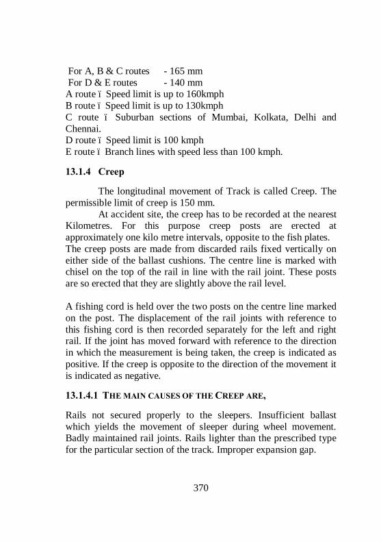
370
For A, B & C routes - 165 mm For D & E routes - 140 mm A route – Speed limit is up to 160kmph B route – Speed limit is up to 130kmph C route – Suburban sections of Mumbai, Kolkata, Delhi and Chennai. D route – Speed limit is 100 kmph E route – Branch lines with speed less than 100 kmph.
13.1.4 Creep
The longitudinal movement of Track is called Creep. The permissible limit of creep is 150 mm. At accident site, the creep has to be recorded at the nearest Kilometres. For this purpose creep posts are erected at approximately one kilo metre intervals, opposite to the fish plates. The creep posts are made from discarded rails fixed vertically on either side of the ballast cushions. The centre line is marked with chisel on the top of the rail in line with the rail joint. These posts are so erected that they are slightly above the rail level. A fishing cord is held over the two posts on the centre line marked on the post. The displacement of the rail joints with reference to this fishing cord is then recorded separately for the left and right rail. If the joint has moved forward with reference to the direction in which the measurement is being taken, the creep is indicated as positive. If the creep is opposite to the direction of the movement it is indicated as negative.
13.1.4.1 THE MAIN CAUSES OF THE CREEP ARE,
Rails not secured properly to the sleepers. Insufficient ballast which yields the movement of sleeper during wheel movement. Badly maintained rail joints. Rails lighter than the prescribed type for the particular section of the track. Improper expansion gap.

371
Decay of sleepers. Uneven spacing of sleepers. Loose and uneven packing. Rail seat worn out in the metal sleepers.
13.1.4.2 REPERCUSSIONS OF THE CREEP ON THE TRACK
The Creep in the track causes, The sleepers to go out of square, Distorts the gauge, Shears/ Breaks the fastenings, fish plates, Buckling of the Track in some extreme cases.
14 DISASTER MANAGEMENT
The term disaster applies to an occurrence which results in huge loss of lives and property, injuries to people, dislocation to normal life etc. Natural calamities such as earth quakes, Tsunami, Volcanic eruption, building collapses, wild fires etc, and avoidable occurrences like train accidents, gas pipe line fires, poisonous gas leaks from factories etc are examples of disasters. In railway parlance, disaster refers to a major accident involving loss of lives and dislocation to through traffic. The art of handling such an occurrence without panicking and taking quick decisions with a cool mind to alleviate the sufferings of the passengers involved and restore normalcy of train operation with minimum delay even in the absence of communication facilities and without waiting for directions from higher-ups, is known as disaster management. The Railway system is a time tested system and have at their command, the most sophisticated equipment for rescue and relief, medical assistance, re-railing and removal of obstructions, material handling etc., in addition to well trained personnel. At the accident site, the Engine crew, Guard, TTEs or any Railway official travelling by the train on duty or off duty will be the first person to manage the disaster.

372
The Disaster management involves Intelligent and meticulous planning Prompt response to the situation Adequate post-disaster measures The objectives of Diaster Management in the order of priority will be: Protection of the unaffected line. Prevent / Minimize loss of lives, immediate medical relief. Quick attention to the injured, transporting them to the nearest hospital. Protection to the belongings of the passengers. Provision of food, communication facilities and transportation to the stranded passengers. Protection of Railway property. Quick relay of correct information to all concerned including the next of kin of the dead and injured, media and Control office. Extrication of dead bodies and moving them to safe places. Quick movement of essential materials and personnel to the accident spot. Preservation of the clues at site. Speedy relief and restoration of traffic. The Station Masters of the nearest stations, the Control Office and the Zonal Head quarters will act fast to communicate the information to Civil Authorities at various levels to mobilise medical relief from the nearest places, medical treatment at the nearest hospitals, transport to the stranded passengers and assistance from Police and Fire fighting wings. Assistance of Military and Para military forces will also be enlisted if necessary. The Station Masters of the nearest stations will also assess the extent of loss of lives, grievous injuries and damage to railway property and communicate to Control Office for arranging proper rescue, relief and restoration facilities with least delay. THE GOLDEN HOUR Golden hour is the first one hour immediately after an accident.
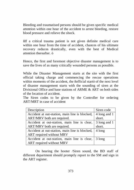
373
Bleeding and traumatised persons should be given specific medical attention within one hour of the accident to arrest bleeding, restore blood pressure and relieve the shock. “If a critical trauma patient is not given definite medical care within one hour from the time of accident, chances of his ultimate recovery reduces drastically, even with the best of Medical attention thereafter. ” Hence, the first and foremost objective disaster management is to save the lives of as many critically wounded persons as possible. While the Disaster Management starts at the site with the first official taking charge and commencing the rescue operations within moments of the accident, the “official start” of the next level of disaster management starts with the sounding of siren at the Divisional Office and base stations of ARME & ART on both sides of the location of accident. The Siren codes to be given by the Controller for ordering ART/MRT in case of accident
Description Siren code Accident at out-station, main line is blocked, ART/MRV both are required.
4 long and 1 short.
Accident at out-station, main line is clear, ART/MRV both are required.
3 long and 1 short.
Accident at out-station, main line is blocked, ART required without MRV
4 long
Accident at out-station, main line is clear, ART required without MRV
3 long
On hearing the hooter /Siren sound, the BD staff of different department should promptly report to the SM and sign in the ART register.

374
The Medical relief van should start from the base station within 20 minutes and ART should start within 30 minutes during day and 45 minutes during night. When passenger carrying trains meet with accident, normally MRV is moved first. Subsequently it may be cancelled en route if the injuries are trivial or nil. The line is kept clear for the passage of MRV/ART, by regulating the trains in the section. On reaching the site, all departments will deploy their personnel in the rescue work at first. Once the entire injured are removed to safer places, all dead bodies will be removed and moved away from the accident spot, to be handed over to the next of kin. To extricate the injured and dead, cold cutting equipment only shall be used, in order to avoid risk of fire. MRV are equipped with under-water cutting equipment and pneumatic inflatable cushions to retrieve bodies from under water and under capsized coaches. Emergency cells are formed at: Divisional Control Office Zonal Control Office Stations on both side of the accident site At the accident site The emergency cells will be continuously monitoring and logging the events from the accident site and respond to the demands for assistance from the site. Movement of special equipment and gadgets, experts from various government and private agencies, recording the details of the dead and injured, the details of passengers under treatment in various hospitals and logging the rescue and relief operations in a chronological sequence. Meanwhile, transport is arranged for the stranded passengers for their onward journey. This may be in the form of road transport or rail transport depending upon the circumstances. Unaffected portions of the accident involved train may be moved, but only after checking the stock for safety and recording all tell

375
tale clues on the stock. The movement of unaffected portion has to be authorised by the DRM and the stock should be kept in the nearby stations for inspection by CRS, Police and forensic experts. Once the primary objective of minimising the loss of lives and mitigating the hardship of the stranded are finished, the relief operation shall commence. This will be a two-fold operation, taking care of recording the various clues and parameters of the track, signalling equipment rolling stock etc and the other attending to removal of obstructions and restoration of track. By now, a reasonable assessment of the probable time of restoration can be made and the emergency cells updated with the information, for regulating, cancelling, rescheduling and diverting the trains which cater to the section. The pre-planning and preparation for Disaster management team Relief equipment viz Medical Relief Van(MRV) and Accident Relief Train (ART) should be located at strategic points and should be accessible for immediate despatch. Station staff must maintain an up to date list of Medical facilities available near by and how to get assistance when needed. Brake Van Equipment Viz Emergency lighting equipment, portable field telephones, stretchers, Fire extinguishers must be available on trains and staff must be familiar with their use. A list of First aiders must be available with the SM for calling them in case of emergency. Mock drills must be conducted periodically to test the effectiveness of the relief operations and to know and correct the short comings. ART/MRV must be inspected monthly by the DMO, SMR, ADEN, ADEE and ADME along with the in charges of ART/MRV.

376
14.1.1 The responsibilities of Railway staff in the event of accident:
14.1.1.1 CREW OF THE ACCIDENT INVOLVED TRAIN;
The crew of the train involved in accident must promptly communicate to the controller and the nearest SM giving the essential details of the accident and the assistance required. Use the portable field telephone/VHF for faster communication. Halt the train running on adjacent lines and send memo to the nearest SM through the Driver/Guard. Detach the train engine after taking adequate precaution to secure the load, to reach the nearest station. Send assistant guard/assistant driver to the nearest station by foot when all other means fail.
14.1.1.2 SENIOR MOST OFFICIAL AVAILABLE AT THE ACCIDENT SPOT;
Promptly convey the information to the control and the SM on either side about the details of the accident and the assistance required. Collect the railway men and volunteers and allot duties to each of them to assist the passengers. If there are doctors and nurses on the train, get their help and expertise. Get help from the police, military, RPF personnel if available on the train for rescuing the passengers and for protecting their property.
14.1.1.3 GUARD OF THE ACCIDENT INVOLVED TRAIN SHOULD
Arrange to protect the adjacent line/lines if necessary and the line to which the accident has occurred. Send information through quickest means to the control and SM on either side. Take action to save lives and render first aid, with the help of the first aid box available in the Brake van. Call for the doctors on the train and seek their assistance. Seek assistance of the railway men on the train for attending to the injured and for other relief operations. Post a railway employee to man the field telephone to ensure regular flow of information to the control. Make a quick

377
assessment of the assistance needed and advice control or Nearest SM. Preserve and safeguard all clues to arrive at the possible cause of Accident. Arrange protection of property of passengers and railway property through RPF, GRP and other railway staff. Do not leave the site till you are permitted by a competent railway authority.
14.1.1.4 STATION MASTER OF THE SECTION
Protect the affected section. Issue caution orders to trains going on adjacent lines (on double line/multiple line section), to exercise caution. Inform control about the time of accident, location, nature of assistance required. Arrange to dispatch medical aid to the injured passengers with the help of First aiders and local doctors. Maintain liaison with the accident manager at the spot. Order ART/MRV as per needs with more backup assistance.
14.1.1.5 SECTION CONTROLLERS
Order ART/MRV as required, duly getting approval from the competent authority. Pass information to all concerned. Arrange clearance of unaffected portion of the train from the site at the earliest. Plan its onward dispatch. Arrange transport of injured/Stranded passengers to hospitals/Stations. (Where drinking water and catering facilities are available). Arrange regulation/Diversion/Cancellation of trains. Keep in touch with the Accident Manager of the site. Must have road map, Locations of Major hospitals etc, over their Railway system for ready reference.
14.1.2 The responsibilities of various departments during Accident:
14.1.2.1 COMMERCIAL DEPARTMENT
Taking care of passengers & their belongings. Arranging transportation for the stranded. Collect the names, addresses and ticket particulars of the dead/injured Passengers. Taking care of

378
catering needs of passengers and staff working at site. Arranging ex-gratia payment to injured. Processing application for claims in case of casualty from the kith & kin. Updating the details of casualty/injured from hospitals and places where treated. Pass on the updated information to emergency cell from time to time.
14.1.2.2 SECURITY DEPARTMENT
Cordoning the affected area. Protecting the belongings of the passengers. Controlling of the crowd. Render help to the stranded passengers. Facilitate fire fighting arrangements etc, Check for possibilities of sabotage & their Clues, if any.
14.1.2.3 S&T DEPARTMENT
If signaling equipment are involved as probable cause of the accident, the block instrument & relay rooms will be sealed after recording the positions of levers, knobs, slides, indications etc. Repairing & restoring to service after recording the parameters. Providing portable & emergency telephone sets, Satellite, BSNL, & Railway lines with STD facilities at Site, mobile phones, fax and internet facilities for use by railway officials and stranded passengers. Providing hot line between site & divisional HQ and Zonal HQ. Providing PA system at the site.
14.1.2.4 MEDICAL DEPARTMENT
Setting up temporary hospital & rendering First aid. Providing medical treatment to save the lives of the injured. Surgical attention if necessary in the temporary operation theatre of MRV. Getting assistance from nearby hospitals, health units. Visiting the hospitals where injured are undergoing treatment and arranging further treatment for them.

379
14.1.2.5 ENGINEERING DEPARTMENT
Joint inspection & recording of parameters and clues at the site; Preparation of site plan. Removal of damaged P.Way materials from the vicinity for laying of track. Assisting the Mechanical staff for preparation of surface for propping, removal of vegetation to facilitate smooth working. Repairing/ laying new track to restore traffic. Arranging heavy duty equipment such as bull dozers, tipplers, road cranes. JCB etc for assisting the repair work;
14.1.2.6 TRACTION DEPARTMENT
Switch off the overhead power for crane working. Removing the damaged power lines. Lowering & slewing the power lines for crane working. Earthing the power lines, where ever required. Restoring the power lines, after the crane work. Ensuring the restoration of the over head power lines
14.1.2.7 ELECTRICAL DEPARTMENT
Providing sufficient lighting arrangements at the site, including focusing lights, generator sets etc. Providing charging facilities for stabled ARME & ART. Providing uninterrupted power supply to computers, Fax machine etc
14.1.2.8 OPERATING DEPARTMENT
Quick movements of MRV & ART to the site. Arrangements for relief trains for the stranded passengers for onward journey. Quick movement of materials for as needed by individual departments. Assessment of the probable time of restoration in consultation with other branches and arranging for rescheduling, diverting etc
14.1.2.9 SAFETY DEPARMENT
Coordinating the work of recording of clues, track parameters, rolling stock parameters etc. Collecting the statements of Engine

380
crew, Guard and other railway staff on duty on the train. Arranging to freeze the maintenance records of the concerned departments Arranging for Medical examination of the train crew. Arranging for video graph and photographs of the track, coaches etc. Collecting the event recorder/speed recorder from loco and decoding the same
14.1.2.10 MECHANICAL DEPARMENT
Joint inspection & recording of parameters and clues at the site. Planning the re-railment /removal of obstruction from both ends, using cranes and MFD equipment. Removing trapped persons/ bodies using cold cutting equipment, Hydraulic rescue device etc. Assisting other branches for moving bulky objects like girders, using crane.
14.1.2.11 STORES DEPARTMENT
Arranging supply of spares urgently needed for the equipment involved in rescue/relief work. Ensuring availability of stationery, computer peripherals etc. Procuring life saving drugs for the critically wounded. Information to the press should be given in a clear unambiguous manner giving factual information. Divisional Railway manager normally deals with press persons. Responsible officers must reach to the site of accident as early as possible by the first available means, viz. rail, road or air. It is important that Doctors only, should normally categories death/Serious injury/Minor injury after their examination of passengers. Medical officers in charge must maintain records of injuries, treatment given to the patients.

381
15 INDIAN RAILWAY CONFERENCE ASSOCIATION (IRCA)
Indian Railway Conference Association situated in New Delhi frames rules for maintenance of Rolling stock both in workshops and in open lines, prescribing the standard and condemning sizes of various components used on a rolling stock. The rulebooks issued for the Carriage & Wagon department are: Part III - For Wagon Stock (Issued in 1973, further review under progress) Part IV - For Coaching Stock (latest issued in 2003) IRCA Part III and IV contains 4 chapters Chapter Details Chapter I Definitions Chapter II Workshop repair practice Chapter III Maintenance practice in open line Chapter IV Rejection rules
15.1.1.1 CODE OF WORKSHOPS
Every workshop is given with a 5 digit code - XXYZZ XX - the first two digits indicates the Zonal Railway Y - The third digit indicates the type of Workshop ZZ - The last two digits indicates the individual number of the workshop Different zones and their head quarters of Indian Railway and their codes Sl No Name of the Railway Code Head Quarters

382
1 Central Railway 01 Mumbai 2. Eastern Railway 02 Kolkota 3. Northern Railway 03 New Delhi 4. North Eastern Railway 04 Ghorakpur 5. North Frontier Railway 05 Maligon 6. Southern Railway 06 Chennai 7. South Eastern Railway 07 Kolkota 8. Western Railway 08 Mumbai 9. South Central Railway 09 Secundrabad 10. East Central Railway 10 Hajipur 11. North Western Railway 11 Jaipur 12. East Coast Railway 12 Bhuvaneshwar 13. North Central Railway 13 Allahabad 14. South East Central Railway 14 Bilaspur 15. South Western Railway 15 Hubli 16. West Central Railway 16 Jabalpur Type of Workshop Code Loco Workshops 1 Carriage & wagon Workshops 2 Loco, Carriage & Wagon Workshops 3
15.1.1.2 THE DIFFERENT WORKSHOPS IN THE INDIAN RAILWAYS ARE;
Sl. No
Railway Name of the workshop Code
1 2 3
Central 01 Parel Matunga Kurduwadi
01101 01201 01301
4 5 6
Eastern 02 Jamalpur Kancharapara(Loco) Kancharapara(C&W)
02101 02102 02201

383
7 Lilluah 02202 8 9 10 11 12
Northern 03 Charbagh Amritsar Alambagh Jagadhri Kalka
03101 03102 03201 03202 03203
13 14
North Eastern 04 Gorakhpur Izat Nagar
04301 04302
15 16 17
North East Frontier 05
New Bongaigaon Dibrugargh Tinddharia
05201 05301 05302
18 19 20
Southern 06
Perambur (Loco) Perambur (C&W) Golden Rock
06101 06202 06303
21 South Eastern 07 Kharagpur 07301 22 23 24 25 26
Western 08 Dahod Parel & Mahalaxmi Junagarh Pratapnagar Bhavnagar
08301 08201 08202 08302 08203
27 28 29
South Central 09 Guntapalli Tirupati Lallaguda
09201 09202 09203
30 East Central 10 Samastipur 10201 31 32 33 34
North Western 11 Ajmer (Loco) Ajmer (C & W) Jodhpur Bikaner
11301 11201 11202 11203
35 East Coast 12 Mancheshwar 12201 36 North Central 13 Jhi 13201 37 38
S.E. Central 14 Raipur Nagpur
14201 14301
39 40
S. Western 15 Mysore Hubli
15201 15202
41 West Central 16 Bhopal 16201

384
42 Kota 16202
15.2 CHAPTERS
Chapter I: This chapter deals with definitions For the purposes of these rules, the following terms will have the meaning herein assigned to them. Owning Railway:- It is the railway to which the vehicle belongs. Using Railway:- It means a railway using a junction worked by another railway. Working Railway:- It means a railway working a junction. Rolling stock: Includes both coaching and goods stock. Goods stock:- It me all goods wagons and includes all rolling stock other than coaching stock, irrespective of contents and whether attached to passenger or goods trains. Coaching stock: It comprises all coaching vehicles including fish v, milk v, self propelled vehicles such as rail cars, electric multiple units, diesel electric multiple units, goods wagons intended for coaching traffic etc. Goods wagons intended for coaching traffic should be marked as prescribed and used for coaching traffic only.

385
Note: i) The term vehicle applies to coaching stock only. ii) The term wagon applies to goods stock only. Passenger Coaching Vehicles (PCV): It comprises coaching stock used exclusively for carrying passengers, and includes composite carriages of which the whole or part is allotted for carrying passengers. Other Coaching Vehicles (OCV): It comprises saloons and inspection carriages and includes tourist cars, restaurant cars, kitchen cars, construction cars, parcel and horse v, fish v, milk v, motor and parcel v composite luggage and brake v, etc. Train: Means an engine with or without vehicles attached, or any self-propelled vehicle with or without a trailer, which cannot be readily lifted off the track. Passenger train: Means a train intended solely or mainly for the carriage of passengers and other coaching traffic, and includes a troop train. Diesel Rail Cars: These are self-propelled diesel engine driven coaching vehicles used for short distance fast services and can be used in single or multiple unit operation with or without trailers. Electric Multiple Unit (EMU): These consist of one self-propelled motor coach, one Trailer coach and one Driving trailer coach for DC traction, and one self-propelled Driving motor coach along with 2 or 3 trailer coaches for AC traction. Rake consists of 2, 3 or 4 units. EMU's are 3660 mm

386
wide stock and operates only in the suburban section of four metropolises. The coaches are equipped with EP brakes. Mainline Electric Multiple Unit (MEMU): These consist of one self-propelled driving motor coach and three trailer coaches. Rake consists of either 2, 3 or 4 units. MEMU`s are 3250 mm wide stock and operates in the short distance mainline AC electrified section. The coaches are equipped with EP brakes. Diesel Multiple Unit (DMU)/(DHMU): These consist of one driving power car, one trailer coach and one driving trailer coach. Rake consists of either 2 or 3 units. DMU`s are 3250 mm wide stock and operates in the non-electrified mainline routes. Power cars are either provided with electric transmission (DEMU) or hydraulic transmission (DHMU). The coaches are provided with air brakes. Gross load at rail: It is the sum of the maximum carrying capacity and the tare of the vehicle as marked thereon, divided by the number of axles. Air-conditioned coach: It includes fully or partially air-conditioned portions of a coach where the temperature in the air-conditioned portions is maintained within a predetermined range. Anti-telescopic coach: It is a coach with a suitably designed shell as incorporated in the ICF and BEML designs. Bogie: It is a general term for the assembly of all suspension parts, which together support the coach body at the two ends. It includes the structural frame, wheels, axles and bearings, suspension links and springs etc

387
Primary suspension means the spring arrangement between the bogie frame and axle box. Secondary suspension means the spring arrangement between the coach body and the bogie frame. Anchor-link/Drag-link: It is a device for transferring the tractive and braking forces between the carriage body and the bogie, as fitted on the ICF and BEML bogies respectively. Shock Absorber: It is a double acting telescopic hydraulic device for damping vibrations caused on the run, thereby contributing to comfortable riding. Hot Box: Every journal which runs warm necessitating a vehicle, wagon or brake van being detached from a train from the commencement of its journey to its booked destination inclusive should be considered a hot box. Electrical equipments. Dynamo/Alternator: It is an electrical generator fitted on the under frame/bogie of the coach and driven by a flat belt/ 'V' belts from the pulley fitted on the axle of the bogie. Emergency Coupler: It is a detachable coupler consisting of two 7/2.52 (35 sq.mm) size aluminium cables for providing emergency feed through emergency feed terminal board between two adjacent coaches. Switch Gear:
388
It is the device for control of lights and f as and when required. DC generator/Alternator: It is a regulator used for supplying power to air-conditioning equipments, lights and f and for charging the battery. It takes drive from axle when the coach is running. Motor coupled to generator/pre-cooling rectifier provided on coach works on out side supply for working of AC equipment, lights, f and battery charging when coach is stabled for long period. Condenser motor: It is a motor used for driving the cooling fan of the condenser where the refrigerant is liquefied. Delta panel: It is used for starting and running a 3-phase motor and automatically changes the connection of the motor windings from star to Delta. Thermostat: It is a temperature sensitive device used to control the apparatus for maintaining temperature within pre-determined limits. Expansion Valve: It is used for automatically controlling the flow of refrigerant into the coils of tubing of the evaporator unit, in accordance with the refrigeration duty requirements of the air-conditioner or evaporator. Silent Block: It is a synthetic rubber bonded bush fitted in certain components of the ICF/BEML (HAL/MAN) bogies to facilitate alignment and reduce noise. Slack Adjuster/Brake regulator:

389
It is a mechanical device, which automatically maintains a predetermined distance between the brake blocks and wheel tread and restricts piston travel. Chapter II deals with the Workshop Repair practices. Chapter III deals with maintenance practices in open line. Chapter IV deals with Rejection From workshops, coaching stock must not be allowed with any rejectable, chargeable or other defects. The stock must be turned out after complete repairs, in accordance with prescribed methods and the rules laid down in Chapter-II. The permissible wear and clearances on different components shall confirm to the limits and tolerances specified for workshops by the Chief Mechanical Engineers/Chief Electrical Engineers Maintenance depots shall follow the prescribed procedure and relevant rules in Chapter-II and III and also ensure that coaching stock is not allowed with any rejectable defects. Appndix in IRCA part IV
Appendix Details A-I Particulars of spring suspension A-II Procedure for dismantling, inspection and repairs of
different types of coaching bogies B Trportation codes C Method of periodical inspection and testing of
automatic vacuum brake D Method of periodical inspection of Air brake gear
E Instructions for primary and secondary schedules for mechanical train examining staff
F Instructions for primary and secondary maintenance schedules for electrical department staff

390
16 IN-MOTION ELECTRONIC WEIGHING SYSTEM
CONVENTIONAL STATIC WEIGHING SYSTEM In Static Weighing System each wagon has to be uncoupled from wagons adjacent to it. Wagon has to be carefully positioned on to the weighbridge and then the weight is recorded.
16.1.1.1 DISADVANTAGES OF CONVENTIONAL STATIC WEIGHING SYSTEM:
Loss of time / Delay, Requirement of spare Locomotive Spare manpower is required, Operator error, They need to be constantly maintained and calibrated to ensure their accuracy.
16.1.1.2 ADVANTAGES OF IN-MOTION WEIGHING SYSTEM:
Increased loco and wagon availability, No additional manpower Elimination of operator error, Automatic weighing – analysis More reliable – no moving parts, sealed rugged components which can withstand environmental extremes, Automatic detection of overloading and unbalanced loading, Customer satisfaction due to elimination of delays and the billing information is immediately available
16.1.1.3 BASIC DIFFERENCE BETWEEN THE TWO SYSTEMS:
Every moving body has some vibrations associated with it. A wagon can be thought of a solid mass on springs. When an object is allowed to stop on a weighing scale a fast response is usually not required because in this case any vibration caused by the movement of the object has ample time to die away because of natural damping.

391
In the case of In-motion weighing system some amount of error is inherent due to vibrations arising within the weighing system – caused by impact of wagon on rails and vibrations originating within the object being weighed. The error increases as the speed of the weighment increases.
16.1.1.4 IMPORTANT PARTS OF IN-MOTION WEIGHING SYSTEM:
Weigh Rails, Load cells + track switches, Junction Box, Weight indicator, Peripherals
16.1.1.5 WEIGH RAILS:
Weigh rails are embedded with strain gauge type load cells Load cells convert the weight of the wagon to an electrical signal which is amplified and then filtered to remove high frequency component

392
Measurement of weight: Mechanical scales can weigh literally everything very accurately. However, because they are mechanical they can wear, so they need to be constantly maintained and calibrated to ensure their accuracy.

393
Hence in In-motion weighbridge “Load Cells” are used for weighment.
16.1.1.6 LOAD CELLS:
A load cell is an electronic device and is classified as a force transducer. This device converts force or weight into an electrical signal. There are certain inherent advantages of using a load cell. Load cells are not mechanical. It is also able to offer measurement accuracy within 0.03% to 0.25% of full scale, which is suitable for almost all industrial applications. Strain Gauge: A strain gauge is a device that changes resistance when it is stressed. Since their signal is electrical it can be processed easily. The “strain gauge” is the heart of a load cell. Principle of working of Strain Gauge: Strain is directly proportional to the applied stress. Since electrical resistance of a wire is directly proportional to its length, the electrical resistance of the wire will vary in direct proportion to the strain in the wire. That’s the principle upon which the strain gauge works.

394
A strain gauge's conductors are very thin: it is made of round wire, about 1/1000 inch in diameter. Alternatively, strain gauge conductors may be thin strips of metallic film deposited on a non-conducting substrate material called the carrier. As the surface to which the gauge is attached becomes strained, the wires stretch or compress changing their resistance proportional to the applied load. One or more strain gauges are used in the making of a load cell.

395
Typical strain gauge resistances range from 30 Ohms to 3 kOhms (unstressed). The resistance may change only a fraction of a percent for the full force range of the gauge, given the limitations imposed by the elastic limits of the gauge material and of the test specimen. Thus, in order to use the strain gauge as a practical instrument, we must measure extremely small changes in resistance with high accuracy. For this purpose “Wheatstone Bridge” is used.

396
Wheat stone Bridge:
E=excitation voltage O/P=Output Voltage R1=R3 R2=R4 Under this condition the bridge is said to be balanced and O/P = 0. However, when the bridge is unbalanced the output voltage is not zero and can be measured. Multiple strain gauges are connected to create the four legs of a Wheatstone-bridge configuration. When an input voltage is applied to the bridge, the output becomes a voltage proportional to the force on the cell. This output which is few milli-volts can be amplified and processed by conventional electrical instrumentation
R2
R3
R1
R4
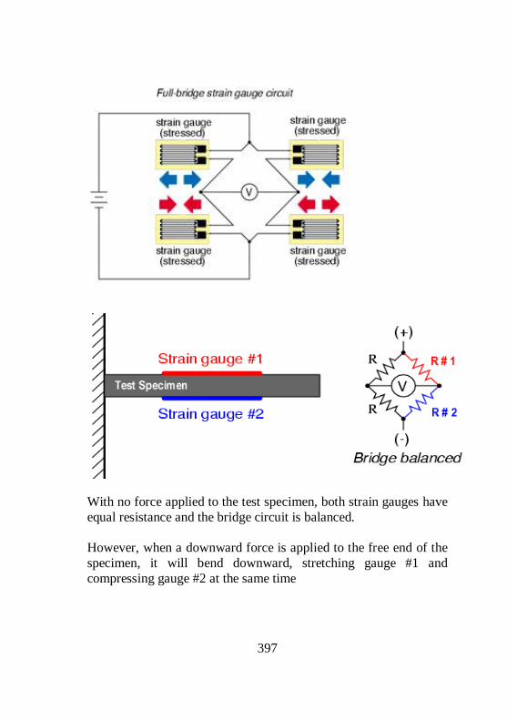
397
With no force applied to the test specimen, both strain gauges have equal resistance and the bridge circuit is balanced. However, when a downward force is applied to the free end of the specimen, it will bend downward, stretching gauge #1 and compressing gauge #2 at the same time

398
Strain gauge bridges are rated in milli-volts of imbalance produced per volt of excitation, per unit measure of force. Quarter-bridge and half-bridge circuits provide an output (imbalance) signal that is only approximately proportional to applied strain gauge force. Linearity, or proportionality, of these bridge circuits is best when the amount of resistance change due to applied force is very small compared to the nominal resistance of the gauge(s). With a full-bridge, however, the output voltage is directly proportional to applied force, with no approximation. Another advantage of full-bridge is that it is unaffected by temperature.
16.1.1.7 TRACK SWITCHES:
Track switch does the following; Monitoring - Approach Speed, Determination - Weighing Speed, Identification - Wagons & Locomotives, Activation - Wagon Weight, Initiates and aborts the weigh cycle, Detection - Roll Back Track switch can be: Mechanical lever type or Induction type – Proximity sensors, Operated by wheel flange Weighing System Electronics: It amplifies and processes the load cells output voltage and displays it in digital form. Track logic detects over-speed, wagon

399
type, initiates weighing process and prevents weighing of locomotives and match trucks. Data System Electronics: It performs all necessary arithmetic functions – net wagon weight, net total weight etc. It also stores weight and other data Two types of Weigh Bridge: WB-15 with maximum speed of 15 km/h for weighing WB-40 with maximum speed of 40 km/h (not successful in the field).
16.1.1.8 FEATURES OF IN-MOTION WEIGH BRIDGE ON INDIAN RAILWAYS:
No speed restriction for trains passing over in non-weigh mode. Possible to weigh isolated wagons axle by axle in static mode Capacity – 30T axle load i.e. 120T gross load Advance over-speed warning system Anti-Roll Back Wagon type identification Weight measurement axle by axle or bogie by bogie Identification of two axle / four axle wagons and locomotives Bi-directional weighing Mixed rake weighing Sturdy Foundation/support Working environment – upto 50°C, tamper-proof Sensitiveness – 10kg Auto calibration of the weighment after each weighment cycle compensation for thermal stresses Able to work under OHE – proper earthing required Track Switches – non-contact type proximity type System free of relay logic Capable of working without air-conditioning

400
DOS/Windows based Wagon Library -10,000 records
16.1.1.9 TESTING PROCEDURE OF WEIGH BRIDGE:
Test/Reference wagons (Already weighed by static weighbridge in uncoupled condition). Rake of minimum 5 and maximum 15 wagons. Not less than 60 wagon weights. In pulling mode readings of up and down directions to be considered separately for calculating accuracy level. No rollback permissible during testing Test should be at constant speed – change in speed in consecutive wagons should not be more than 3 km/h. Anti rollback test – 75% to 25%. Verification and calibration – using static weight. Permissible error – upto 20 t - ± (10kg to 20kg) Site Selection Criteria. Weigh Bridge should be located on a loop line Rail – 52 kg/m; Firm and well settled track; PRC Sleepers Lead-on and Lead-off zones – 500 m on either end No track circuiting in weigh rails, lead-on and lead-off rails – Isolated fish plate joints Earth pit – for OHE Maximum allowable gradient – 1:400
16.1.2 WHEEL IMPACT LOAD DETECTOR (WILD)
Introduction Defective rolling stock produce high impact loads. These loads over a prolonged period of time leads to Rail/Wagon failure, wheel bearing failure etc. WILD measures the impact load independent of the cause. WILD system assists the railway engineer to attend to the defective rolling stock immediately. Reduces Service Failures and unplanned Maintenance Cost of Rolling Stocks & Tracks.

401
WILD is used to catch the defects in the early stage and thereby protecting Rail Infrastructure & avoids Catastrophic Failures. Defects that can cause High Impact Load: Uneven loading, Coil spring weak, Shelled Tread,,Friction liner broken, Snubber spring broken, Axle box canting, PU/CC/EM Pad Shifted/Pressed/Perished, CC Pad housing broken, S/Bearer roof/Friction Liner welding open, Bolster tilted one side, Defect in suspension, Broken spring, Skidded wheel etc.
16.1.2.1 COMPONENTS OF WILD
Instrumented Tracks, Signal conditioning unit, Train trigger sensor Real time embedded controller, Impact load analyzer software, Wireless data transfer, Power back up, Calibration set up Instrumented Track Tracks are instrumented with strain gauges to measure the load pattern of the wheel on the rail. The track consists of 18 Strain gauge measuring channels. Each channel has a full bridge consisting of 4 Rosette type strain gauges.
Signal Conditioning & Data Acquisition Unit:

402
Signals from strain gauges are connected to Signal conditioning unit. There is in built Surge Protection to meet harsh field conditions. Real time embedded controller analyzes the condition of signal and prepares the summary report for publishing in the website System Capabilities Counts number of axles from various measurement channels. Measures Average Dynamic Wheel Load for all wheels. Determines Maximum Dynamic Wheel Load (WA) for all points of contact. Calculates speed of each axle and the average speed of train. Identifies and counts defective wheels as per specified thresholds and rates them according to the severity of defect. Points out exact position of defective wheel from loco for easy examination. Has solar panel providing a power backup. Identifies and count number of Engines, Coaches /Wagons and Brake Vans. Relates each axle with engine or coach / wagon or brake van. Also it’s position in the identified rolling stock. Operates 24x7 without any human assistance. Transmits run reports to a central server that can be accessed by simple web browser. Can operate from a low speed of 30Km/hr. Automation Features: Automatic Diagnosis of faulty channels and switching them off to avoid erroneous data at every start. Automatic start of Data Acquisition (DAQ) on the arrival of train in response to the start trigger switch. Automatic stop of DAQ after the passage of train by intelligently identifying the event. Uploads analyzed data to remote server .

403
Software Flow Starts acquisition once train trigger is received. Logs all the data in to file for analysis. Stops acquisition and logging after the train crosses the instrumented track. Calls an analysis program that loads each channel data and furnishes processed data. Summary report is produced and is transmitted to remote server. Server stores the report and publish in the website. WILD SYSTEM
WILD Site Selection Details These criteria are drafted out based on the site conditions given in COFMOW’s WILD Specification no: COFMOW/IR/WILD/2006 and its recommendation. The system will be installed on straight and level track of minimum 250m length including approaches to the site. There should not be any permanent speed restriction at site of WILD system.

404
The rail section shall be 60Kg/m with flat foot laid on Pre-Stressed Concrete (PSC) sleepers at 60 cm spacing with elastic fastenings viz. pandrol clips on rubber grooved sole and clean ballast cushion of 250/300 mm. The site will not be very close to any station or at the approach of a signal to avoid acceleration or braking over the instrumented rails. The Railways (DRM/Mechanical) shall ensure advance arrangement like sanction etc. to meet out recurring expenditure after one year of installation. The Railways shall ensure provision of reliable 230 V + 10% single phase electric power supply anywhere in 3 Km along track from the site of installation of the system before system installation is taken up by the firm. Site should have proper road approach for taking 13m instrumented rail near site through trailer. Site should have good GSM network connectivity for sending the reports (Preferably TATA INDICOMM.) Proper locality to safe guard the system from Theft / untoward activities. At least one side of the ground area is close to the level of Track and soil is strong and good for earthing. Preferred power connecting from OHE through Auxiliary transformer or near by power resource from Railway infrastructure. Power taken from agriculture field will lead to lot of fluctuation and improper working. LAY OUT OF WILD

405
17 Material Management
Indian Railways is a vast organisation with different department for Running the trains. Hence there is huge involvement of materials for maintenance. To facilitate and ensure the availability of materials in time a separate department called stores department is available in Indian Railways Stores department is involved in purchase of the materials for all the departments. It stocks some materials which are regularly required for day to day activities at convenient location, so that the procurement is made in bulk to get at economical rates. Hence classification of materials at stores department is as below: 1. Stocked items: The materials stocked in the depot for supply. 2. Non-Stocked items: The materials not stocked in the depot, but purchased /manufactured from market and supplied on demand. Further there is stores at each depot of C&W All the materials in a depot are classified as; Imprest Stores, Non-Imprest Stores, Tools & Plant stores, Uniform Stationary (Books & forms), Surplus stores (Movable & Dead).
17.1.1.1 OBJECT OF IMPREST STORES
The object of the imprest stores is to make available a stock of materials for the day-to-day work in depots.

406
17.1.2 Object of Non-imprest stores
The object is to make available certain materials which are not required for the day to day work, but only occasionally to meet some urgent work. Limit of stocking Limit of stocking is based on the anticipated monthly requirements of materials, fixed on the basis of the trend of consumption over the past six months, modified to suit the planned changes in the rolling stock holdings/activities like introduction of additional trains, sick activities etc. Maximum stocking limit Maximum stocking limit for the imprest period is determined on the basis of the distance from the feeding stores depot and the means of transport available for collecting the materials.
17.1.3 Duration of the stocking limit
Stocking limit is normally for the imprest period of 2 months.
17.1.4 Master list
The Master list LM 211 is the monthly consolidated summary of receipts and issues of imprest stores. P L number The Part list No is an eight digit number with the first two numbers indicate the group, the second two numbers indicates the sub group, the third three numbers indicates the serial number of the item the last single number is the check digit.

407
17.1.5 Ledger/tally card
Ledger/Tally card has to be maintained for every individual item and it should contain; The sanctioned quantity P L number and description, Receipts, issues and balance on hand. Different forms used in stores. Sl No.
Form Number
Purpose Remarks
1. S 1830 For recouping the imprest items.
Submitted directly to stores by the depot official. ( 5+1 Copies)
2. S 1313 a. In excess of imprest quantity for stocked items. b.Recoupment of Non-Imprest stocked items.
Approval from DME/Sr.DME is required.(5+1 Copies)
3 S 1302 For recouping the Non -Stocked items if the value of item is less than Rs.50000.
Approval from DME/Sr.DME is required.(1+1 Copies)
4. S 1302A For recouping the Non stocked items if the value of item is more than Rs50000.
Approval from DME/Sr.DME is required.(1+1 Copies)
5 ST 47 Challan for transfer of materials from one depot to the other.

408
6. LM 171 Issue of materials from stores to specified work.
To be signed by the C&W Engineers.
7. T – 136 For the supply of books and forms.
Approval from DME/Sr.DME is required.(1+1 Copies)
8. LM 89N For Repair and returrn If the material is sent to shop directly from the depot. S-1302 should be used if transaction done through stores
09. G 50 F Condemning of all T & P items.
To be condemned by ADME/DME/Sr.DME
10. S-1539 For Disposing the Scrap Items.
DS-8 also can be used.
11. M.268 For condemning the Rolling Stock.
17.1.6 Revision of imprest
Revision is based on the increase or reduction in workload or rolling stock holding. The higher and lower limits are fixed based on the review on the trend of consumption of items for the past six months with justification for increase or reduction. Periodical revision of imprest is done every year. The form to be used is T-409.
17.1.7 Compliance of stores
Based on the stock on hand and quantity supplied every month, the materials are to be treated as: Less than 25% - Nil supply 26% to 75% - Half supply 76% to 100% - Full supply

409
17.1.8 Local purchase of materials
To meet the emergency demands, materials can be purchased locally either with the imprest cash of the depot or that of the DME/Sr.DME to a maximum extent of Rs.300/- for each item. Local purchase can be done through ACOS/DCOS duly placing the indent No. S-1302 (1+1 copies). Out of stock certification must be obtained before processing for local purchase of stocked items. Budgetary Control It is required for the financial discipline to ensure utmost economy in the usage of materials also to keep the consumption levels of materials as low as possible with good maintenance of rolling stock, to ensure that the overall expenditure is contained within the sanctioned budget limits under various demands for the depot. ABC analysis It is a tool used for the effective control of the materials and in turn the budget of the depot. All the items are classified as: Category A: All high value items, few in number, but costing about 80% of the total expenditure. Category B: All medium value items costing about 10 to 12% of the total expenditure. Category C : All low value items bulk of the items about 80% costing only about 8 to 10%. Items are categorized on the basis of total annual cost of items and not on the numerical quantities.

410
Surplus Stores The Surplus stores are classified into, Dead surplus Stores – The items which are not used /Issued for the past 24 months not likely to be used in the near future. Movable surplus Stores - The items which are not used /Issued for the past 24 months and likely to be used within next 12 months.

411