Industrial Training at Air India, New Delhi - Akhil Guliani
46
Acknowledgment I would like to thank Air India for giving me the opportunity to participate in the Internship Program with their Engineering Division at the Indira Gandhi international Airport New Delhi. I would also like to thank Mr Anil Kumar, Cheif manager( S.S.-Trg) for his guidance during the course of the internship. I would also like to thank all the staff at Instrumentation Shop, Radio Shop and ATEC shop for sharing their experiences and wisdom about Aircraft Engineering with me. Akhil Guliani 405IC08 New Delhi 31 January, 2012 1
-
Upload
khangminh22 -
Category
Documents
-
view
3 -
download
0
Transcript of Industrial Training at Air India, New Delhi - Akhil Guliani

Acknowledgment
I would like to thank Air India for giving me the opportunity to participate inthe Internship Program with their Engineering Division at the Indira Gandhiinternational Airport New Delhi.
I would also like to thank Mr Anil Kumar, Cheif manager( S.S.-Trg) forhis guidance during the course of the internship. I would also like to thank allthe staff at Instrumentation Shop, Radio Shop and ATEC shop for sharingtheir experiences and wisdom about Aircraft Engineering with me.
Akhil Guliani405IC08New Delhi31 January, 2012
1

Certificate of Internship
This is to certify that Akhil Guliani of Netaji Subhas Institute of Technologyhas completed his Industrial Training at Air India and has submitted thisreport in partial fulfillment of the requirements of the Internship Programat Air India.
Anil KumarChief Manager,(S.S. - Trg)Air India, New Delhi
Date:
2
Contents
1 Introduction 71.1 An overview of Aircraft Systems and Aviation . . . . . . . . . 71.2 Maintenance of Aircraft . . . . . . . . . . . . . . . . . . . . . 7
1.2.1 Introduction . . . . . . . . . . . . . . . . . . . . . . . . 71.2.2 Line or Routine maintenance . . . . . . . . . . . . . . 71.2.3 Base or Major maintenance . . . . . . . . . . . . . . . 8
1.3 Overhaul Process . . . . . . . . . . . . . . . . . . . . . . . . . 91.4 Objectives of Industrial Training . . . . . . . . . . . . . . . . 10
1.4.1 My Aims and objectives . . . . . . . . . . . . . . . . . 101.4.2 The Roster provided by Air India . . . . . . . . . . . . 10
1.5 Organization of the report . . . . . . . . . . . . . . . . . . . . 11
2 Aircraft Fundamentals 122.1 Introduction . . . . . . . . . . . . . . . . . . . . . . . . . . . . 122.2 Overveiw of an Aircraft . . . . . . . . . . . . . . . . . . . . . 12
2.2.1 Airframe . . . . . . . . . . . . . . . . . . . . . . . . . . 122.2.2 Engine . . . . . . . . . . . . . . . . . . . . . . . . . . . 132.2.3 Avionics . . . . . . . . . . . . . . . . . . . . . . . . . . 14
2.3 Flight Dynamics and Control . . . . . . . . . . . . . . . . . . 152.3.1 Flight dynamics . . . . . . . . . . . . . . . . . . . . . . 152.3.2 Flight control . . . . . . . . . . . . . . . . . . . . . . . 15
2.4 Overveiw of Airbus A-320 Family of Aircrafts . . . . . . . . . 17
3 Instrument Shop 193.1 Introduction . . . . . . . . . . . . . . . . . . . . . . . . . . . . 193.2 Observations . . . . . . . . . . . . . . . . . . . . . . . . . . . 19
3.2.1 Laser gyros . . . . . . . . . . . . . . . . . . . . . . . . 193.2.2 Attitude Indicator (Artificial Horizon) . . . . . . . . . 203.2.3 Flight Recorders . . . . . . . . . . . . . . . . . . . . . 203.2.4 Altimeter . . . . . . . . . . . . . . . . . . . . . . . . . 223.2.5 Air Speed Indicator . . . . . . . . . . . . . . . . . . . 223.2.6 Primary Flight Display . . . . . . . . . . . . . . . . . 23
3

4 Radio Shop 254.1 Introduction . . . . . . . . . . . . . . . . . . . . . . . . . . . . 254.2 Communication Systems in Aviation . . . . . . . . . . . . . . 25
4.2.1 Introduction . . . . . . . . . . . . . . . . . . . . . . . . 254.2.2 VHF . . . . . . . . . . . . . . . . . . . . . . . . . . . . 254.2.3 HF . . . . . . . . . . . . . . . . . . . . . . . . . . . . . 264.2.4 Cockpit voice recorder . . . . . . . . . . . . . . . . . . 26
4.3 Navigation systems in Aviation . . . . . . . . . . . . . . . . . 274.3.1 Introduction . . . . . . . . . . . . . . . . . . . . . . . . 274.3.2 DME . . . . . . . . . . . . . . . . . . . . . . . . . . . . 274.3.3 VOR . . . . . . . . . . . . . . . . . . . . . . . . . . . . 284.3.4 ILS . . . . . . . . . . . . . . . . . . . . . . . . . . . . . 294.3.5 Radar . . . . . . . . . . . . . . . . . . . . . . . . . . . 30
5 ATEC Shop 345.1 Introduction . . . . . . . . . . . . . . . . . . . . . . . . . . . . 345.2 Equipment Testing . . . . . . . . . . . . . . . . . . . . . . . . 34
5.2.1 ATEC . . . . . . . . . . . . . . . . . . . . . . . . . . . 345.2.2 Procedure . . . . . . . . . . . . . . . . . . . . . . . . . 35
A About the Internship 38A.1 Introduction . . . . . . . . . . . . . . . . . . . . . . . . . . . . 38A.2 About Air India . . . . . . . . . . . . . . . . . . . . . . . . . . 38
B ESDS : Electro-Static Discharge Sensitive Devices 40B.1 Introduction . . . . . . . . . . . . . . . . . . . . . . . . . . . . 40B.2 Causes of ESD . . . . . . . . . . . . . . . . . . . . . . . . . . 40B.3 Safety precautions while handling ESDS components . . . . . 41
B.3.1 Identification . . . . . . . . . . . . . . . . . . . . . . . 41B.3.2 Dont’s for handling . . . . . . . . . . . . . . . . . . . . 41B.3.3 Do’s for handling . . . . . . . . . . . . . . . . . . . . . 42B.3.4 Advantages of proper handling . . . . . . . . . . . . . 42
C Cockpit overveiw 43C.1 Introduction . . . . . . . . . . . . . . . . . . . . . . . . . . . . 43C.2 Cockpit Layout . . . . . . . . . . . . . . . . . . . . . . . . . . 43C.3 Instrument Panel . . . . . . . . . . . . . . . . . . . . . . . . . 44
D Author Profile 46
Akhil Guliani 4

List of Tables
1.1 Internship Roster . . . . . . . . . . . . . . . . . . . . . . . . . 10
4.1 Categories of ILS Approaches . . . . . . . . . . . . . . . . . . 31
A.1 Air India Fleet details . . . . . . . . . . . . . . . . . . . . . . 39
5

List of Figures
2.2.1 Jet Engine Cut-away diagram . . . . . . . . . . . . . . . . . . 132.3.1 Flight Dynamics . . . . . . . . . . . . . . . . . . . . . . . . . 152.3.2 Forces acting on an Aircraft . . . . . . . . . . . . . . . . . . . 162.3.3 Aircraft Control surfaces . . . . . . . . . . . . . . . . . . . . . 172.4.1 A320 . . . . . . . . . . . . . . . . . . . . . . . . . . . . . . . . 18
3.1.1 A Generalized Instrumentation system used in Aviation . . . 193.2.1 Attitude Indicator . . . . . . . . . . . . . . . . . . . . . . . . 213.2.2 FDR . . . . . . . . . . . . . . . . . . . . . . . . . . . . . . . . 213.2.3 Internal View of an Aneroid Altimeter . . . . . . . . . . . . . 223.2.4 Internal View of an Air Speed Indicator . . . . . . . . . . . . 233.2.5 PFD . . . . . . . . . . . . . . . . . . . . . . . . . . . . . . . . 23
4.3.1 ILS Sketch . . . . . . . . . . . . . . . . . . . . . . . . . . . . . 304.3.2 Block Diagram of RADAR . . . . . . . . . . . . . . . . . . . . 32
5.2.1 ATEC series 6 . . . . . . . . . . . . . . . . . . . . . . . . . . . 345.2.2 ATEC Modular architecture . . . . . . . . . . . . . . . . . . . 35
A.1.1Air India Logo . . . . . . . . . . . . . . . . . . . . . . . . . . 38
B.1.1ESDS Warning Label . . . . . . . . . . . . . . . . . . . . . . . 40
C.2.1An Airbus A-320 Cockpit . . . . . . . . . . . . . . . . . . . . 44
6

Chapter 1
Introduction
1.1 An overview of Aircraft Systems and Aviation
An aircraft is a vehicle that is able to fly by gaining support from the air,or, in general, the atmosphere of a planet. It counters the force of gravityby using either static lift or by using the dynamic lift of an airfoil, or in afew cases the downward thrust from jet engines.
1.2 Maintenance of Aircraft
1.2.1 Introduction
Aircraft maintenance is the overhaul, repair, inspection or modification ofan aircraft or aircraft component.
Maintenance includes the installation or removal of a component froman aircraft or aircraft subassembly, but does not include:
1. Elementary work, such as removing and replacing tires, inspectionplates, spark plugs, checking cylinder compression, etc.
2. Servicing, such as refueling, washing windows.
3. Any work done on an aircraft or aircraft component as part of themanufacturing process, prior to issue of a certificate of airworthinessor other certification document
1.2.2 Line or Routine maintenance
The maintenance carried out while an airplane is parked at an airport wait-ing for the next takeoff is generally refered to as Line maintenance. It is a 45minute during which the aircraft is refuled and all critical instruments arechecked for defects. Also a comprehensive post flight inspection is carriedout to detect and possibly fix any problems faced by the pilot or the flight
7

crew in general before the next flight. Once the engineereing staff have com-pleted their checks the plane is handed over to the piolt after filling out therelevany paperwork. Pilots are required to follow up with their own preflightInspection. The preflight inspection follows a checklist listing items that thepilot is to visually check for general condition as he or she walks around theairplane. Also, the pilot must ensure that fuel, oil and other items requiredfor flight are at the proper levels and not contaminated. Additionally, it isthe pilot’s responsibility to review the airworthiness certificate, maintenancerecords, and other required paperwork to verify that the aircraft is indeedairworthy.
1.2.3 Base or Major maintenance
Aircraft maintenance checks are periodic inspections that have to be done onall commercial/civil aircraft after a certain amount of time or usage - the mil-itary aircraft normally follow specific maintenance programs which may be ornot similar to the commercial/civil operators. Airlines and other commercialoperators of large or turbine-powered aircraft follow a continuous inspectionprogram approved by the Directorate General of Civil Aviation (DGCA) inIndia or by other airworthiness authorities such as Federal Aviation Agency(FAA) or the European Aviation Safety Agency (EASA). Airlines and air-worthiness authorities casually refer to the detailed inspections as "checks",commonly one of the following: A check, B check, C check, or D check. Aand B checks are lighter checks, while C and D are considered heavier checks.
1. Category A-Check:
This is performed approximately every 500 - 800 flight hours. It needsabout 20 man-hours and is usually performed overnight at an airportgate. The actual occurrence of this check varies by aircraft type, thecycle count (takeoff and landing is considered an aircraft "cycle"), orthe number of hours flown since the last check. The occurrence can bedelayed by the airline if certain predetermined conditions are met.
2. Category B-Check:
This is performed approximately every 4-6 months. It needs about150 man-hours and is usually performed within 1-3 days at an airporthangar. A similar occurrence schedule applies to the B check as to theA check. B checks may be incorporated into successive A checks, ie:A-1 through A-10 complete all the B check items.
3. Category C-Check:
This is performed approximately every 15–21 months or a specificamount of actual Flight Hours (FH) as defined by the manufacturer.This maintenance check is much more extensive than a B Check, as
Akhil Guliani 8

pretty much the whole aircraft is inspected. This check puts the air-craft out of service and until it is completed, the aircraft must notleave the maintenance site. It also requires more space than A and BChecks - usually a hangar at a maintenance base. The time needed tocomplete such a check is generally 1-2 weeks and the effort involvedcan require up to 6000 man-hours. The schedule of occurrence hasmany factors and components as has been described, and thus variesby aircraft category and type.
4. Category D-check:
This is - by far - the most comprehensive and demanding check for anairplane. It is also known as a Heavy Maintenance Visit (HMV). Thischeck occurs approximately every 5–6 years. It is a check that, more orless, takes the entire airplane apart for inspection and overhaul. Also,if required, the paint may need to be completely removed for furtherinspection on the fuselage metal skin. Such a check will usually demandaround 40.000 man-hours and it can generally take up to 2 months tocomplete, depending on the aircraft and the number of techniciansinvolved. It also requires the most space of all maintenance checks,and as such must be performed at a suitable maintenance base. Giventhe requirements of this check and the tremendous effort involved in it,it is also the most expensive maintenance check of all, with total costsfor a single visit being well within the million-dollar range. Becauseof the nature and the cost of such a check, most airlines - especiallythose with a large fleet - have to plan D Checks for their aircraft yearsin advance. Ofttimes, older aircraft being phased out of a particularairline’s fleet are either stored or scrapped upon reaching their nextD Check, due to the high costs involved in it in comparison to theaircraft’s value. On average, a commercial aircraft undergoes 2-3 DChecks before it is retired. As such, only few of these shops offer Dchecks.
1.3 Overhaul Process
The following steps are taken by an engineer to service and overhaul a faultyinstrument:
1. Check the testing equipment for:
(a) Serviceability; weather in working condition or not.
(b) Calibration or Error chart; the amount of error present in thereadings last checked and when due.
(c) Connectors; for damage so as to protect the equipment.
Akhil Guliani 9

2. Test the testing equipment in self-test mode yourself to assure service-ability and avoid equipment failure.
3. Assure that the required power supply is available and in serviceablecondition. 1
4. Take proper ESDS (Electro-Static Discharge Sensitive) safety precau-tions for required equipment.
5. Connect Equipment to the tester and the power supply.
6. Read the technical manuals and documentation provided by the com-ponent manufacturer.
7. Follow step by step the overhaul and servicing instructions given in thedocumentation.
8. Check the error chart and correct the readings accordingly.
9. Fill the documentation with the relevant data and update the compo-nent service history to keep track of the components serviceability.
1.4 Objectives of Industrial Training
1.4.1 My Aims and objectives
1. To understand the underlying principles of the components availablein the workshop.
2. To observe the ongoing process of component maintenance, repair andoverhaul (MRO).
3. Get an engineer’s perspective into role of an Instrumentation and Con-trol Engineer in Avionics
1.4.2 The Roster provided by Air India
Table 1.1 gives details about the duration of posting at various labs duringthe course of the internship.
S.No. Workshop Attended Duration1 Instrumentation Shop 21/12/2011 to 09/01/20122 Radio Shop 10/01/2012 to 24/01/20123 ATEC Shop 25/01/2012 to 31/01/2012
Table 1.1: Internship Roster1According to a survey around 25% of all equipment failures that happen in the industry
are caused due to the application of incorrect power supply.
Akhil Guliani 10
1.5 Organization of the report
This report is organized in the following manner:Chapter 1 gives an overview of the knowledge gathered during the course
of internship and aims and objectives of the internship.Chapter 2 explains in breif a few critical concepts about an aircraftsChapter 3 gives details about the Instrument shop and aircraft instru-
ment systems.Chapter 4 gives details about the Radio shop and aircraft communication
and navigation systems.Chapter 5 gives details about the ATEC shop,and equipment testing.The rest of the report is contained in the appendices, due to the simple
reason that aviation is a field having immense depth which cannot be coveredentirely in any one document or chapter hence to keep the report to the pointand properly informative I decided to include relevant additional informationas part of the appendix, which has been organized as follows:
Appendix A gives details about the internship at Air IndiaAppendix B talks about the ESDS (Electro-Static Discharge Sensitive)
devices and related precautions to be taken during the MRO process forthem.
Appendix C gives a breif overview of the cockpit.Appendix D gives a brief about the author.
Akhil Guliani 11

Chapter 2
Aircraft Fundamentals
2.1 Introduction
An aircraft is a vehicle that is able to fly by gaining support from the air,or, in general, the atmosphere of a planet. It counters the force of gravityby using either static lift or by using the dynamic lift of an airfoil, or ina few cases the downward thrust from jet engines. The human activitythat surrounds aircraft is called aviation. The following sections give a breifaccount of the aircraft.
2.2 Overveiw of an Aircraft
The parts of an aircraft are generally divided into three categories:
1. The airframe comprises the mechanical structure and associated equip-ment.
2. The propulsion system (if it is powered) comprises the engine or enginesand associated equipment.
3. The avionics comprise the electrical flight control and communicationsystems.
2.2.1 Airframe
The airframe of an aircraft is its mechanical structure. The main partsof the airframe are the fuselage, wing, stabilising tail or empennage, andundercarriage.
Fuselage is an aircraft’s main body section containing the crew cockpit orflight deck, and any passenger cabin or cargo hold. In single- andtwin-engine aircraft, it will often also contain the engine or engines.The fuselage also serves to position control and stabilization surfaces
12

in specific relationships to lifting surfaces, required for aircraft stabilityand maneuverability.
Wing The wings of an aircraft produce lift. Many different styles and ar-rangements of wings have been used on heavier-than-air aircraft, andsome lighter-than-air craft also have wings. Most early fixed-wing air-craft were biplanes, having wings stacked one above the other.
Stabilising and control surfaces Most aircraft need horizontal and ver-tical stabilisers which act in a similar way to the feathers on an arrow.These stabilising surfaces allow equilibrium of aerodynamic forces andto stabilise the flight dynamics of pitch and yaw. Flight control sur-faces enable the pilot to control an aircraft’s flight attitude and areusually part of the wing or mounted on, or integral with, the associ-ated stabilising surface.
Undercarriage, or landing gear, is the structure that supports an aircraftwhen it is not flying and allows it to taxi, take off and land. Mostcommonly, wheels are used but skids, floats, or a combination of theseand other elements can be used, depending on the surface. Manyaircraft have undercarriage that retracts into the wings and/or fuselageto decrease drag during flight.
2.2.2 Engine
An aircraft engine is the component of the propulsion system for an aircraftthat generates mechanical power. The most comman type of engine usedin commercial aircrafts are jet engines. A jet engine is a reaction enginethat discharges a fast moving jet which generates thrust by jet propulsion.The exhaust nozzle produces thrust for the jet; the hot airflow from the
Figure 2.2.1: Jet Engine Cut-away diagram
engine is accelerated when exiting the nozzle, creating thrust, which, in
Akhil Guliani 13

conjunction with the pressures acting inside the engine which are maintainedand increased by the constriction of the nozzle, pushes the aircraft forward.The primary engine maintained at the MRO was the IAE V2500; which is aturbofan variety of jet engine.
2.2.3 Avionics
Avionics is a term used to describe all of the electronic systems used onaircraft, artificial satellites and spacecraft. Avionic systems include commu-nications, navigation, the display and management of multiple systems andthe hundreds of systems that are fitted to aircraft to meet individual roles.
The cockpit of an aircraft is a typical location for avionic equipment, in-cluding control, monitoring, communication, navigation, weather, and anti-collision systems. The majority of aircraft power their avionics using 14 or28 volt DC electrical systems; however, larger, more sophisticated aircrafthave AC systems operating at 400 Hz, 115 volts AC. International standardsfor avionics equipment are prepared by the Airlines Electronic EngineeringCommittee (AEEC).
the following gives a brief about some typical avionics equipments:
1. Communications connect the flight deck to the ground and the flightdeck to the passengers. On-board communications are provided bypublic address systems and aircraft intercoms.
2. Aircraft flight control systems; today automated flight control is com-mon to reduce pilot error and workload at key times like landing ortakeoff.Autopilot was first invented by Lawrence Sperry during WorldWar II to fly bomber planes steady enough to hit precision targets from25,000 feet. Today it’s equipped on most commercial planes to reducepilot error and workload at key times such as landing or takeoff.
3. Flight recorder; commercial aircraft cockpit data recorders, commonlyknown as a “black box”, store flight information and audio from thecockpit. They’re often recovered from a plane crash to determine thecause of the incident.
4. Weather systems such as weather radar and lightning detectors areimportant for aircraft flying at night or ininstrument meteorologicalconditions, where it is not possible for pilots to see the weather ahead.Heavy precipitation (as sensed by radar) or severe turbulence are bothindications of strong convective activity and severe turbulence, andweather systems allow pilots to deviate around these areas.
Akhil Guliani 14

2.3 Flight Dynamics and Control
2.3.1 Flight dynamics
is the science of air vehicle orientation and control in three dimensions. Thethree critical flight dynamics parameters are the angles of rotation in threedimensions about the vehicle’s center of mass, known as pitch, roll, and yaw(quite different from their use as Tait-Bryan angles).
Figure 2.3.1: Flight Dynamics
Roll is a rotation about the longitudinal axis (equivalent to the rolling orheeling of a ship) giving an up-down movement of the wing tips mea-sured by the roll or bank angle.
Pitch is a rotation about the sideways horizontal axis giving an up-downmovement of the aircraft nose measured by the angle of attack.
Yaw is a rotation about the vertical axis giving a side-to-side movement ofthe nose known as sideslip.
2.3.2 Flight control
Aerospace engineers develop control systems for a vehicle’s orientation (atti-tude) about its center of mass. The control systems include actuators, whichexert forces in various directions, and generate rotational forces or momentsabout the aerodynamic center of the aircraft, and thus rotate the aircraftin pitch, roll, or yaw. For example, a pitching moment is a vertical forceapplied at a distance forward or aft from the aerodynamic center of the air-craft, causing the aircraft to pitch up or down. Control systems are alsosometimes used to increase or decrease drag, for example to slow the aircraftto a safe speed for landing.
The two main forces acting on any aircraft are lift supporting it in the airand drag opposing its motion. Control surfaces may also be used to affectthese forces directly, without inducing any rotation.
The main control surfaes of an aircraft are :
Akhil Guliani 15

Figure 2.3.2: Forces acting on an Aircraft
Ailerons Ailerons are mounted on the trailing edge of each wing near thewingtips and move in opposite directions. When the pilot moves thestick left, or turns the wheel counter-clockwise, the left aileron goesup and the right aileron goes down. A raised aileron reduces lift onthat wing and a lowered one increases lift, so moving the stick leftcauses the left wing to drop and the right wing to rise. This causes theaircraft to roll to the left and begin to turn to the left. Centering thestick returns the ailerons to neutral maintaining the bank angle. Theaircraft will continue to turn until opposite aileron motion returns thebank angle to zero to fly straight.
Elevator An elevator is mounted on the trailing edge of the horizontal sta-bilizer on each side of the fin in the tail. They move up and downtogether. When the pilot pulls the stick backward, the elevators goup. Pushing the stick forward causes the elevators to go down. Raisedelevators push down on the tail and cause the nose to pitch up. Thismakes the wings fly at a higher angle of attack, which generates morelift and more drag. Centering the stick returns the elevators to neu-tral and stops the change of pitch. Many aircraft use a stabilator —a moveable horizontal stabilizer — in place of an elevator. Some air-craft, such as an MD-80, use a servo tab within the elevator surface toaerodynamically move the main surface into position. The directionof travel of the control tab will thus be in a direction opposite to themain control surface. It is for this reason that an MD-80 tail looks likeit has a ’split’ elevator system.
Rudder The rudder is typically mounted on the trailing edge of the verticalstabilizer, part of the empennage. When the pilot pushes the left pedal,the rudder deflects left. Pushing the right pedal causes the rudder todeflect right. Deflecting the rudder right pushes the tail left and causes
Akhil Guliani 16

Figure 2.3.3: Aircraft Control surfaces
the nose to yaw to the right. Centering the rudder pedals returns therudder to neutral and stops the yaw.
2.4 Overveiw of Airbus A-320 Family of Aircrafts
The Airbus A320 family consists of short- to medium-range, narrow-body,commercial passenger jet airliners manufactured by Airbus Industrie.[Nb 1]The family includes the A318, A319, A320 and A321, and the ACJ businessjet. Final assembly of the family in Europe takes place in Toulouse, France,and Hamburg, Germany. Since 2009, a plant in Tianjin in the People’sRepublic of China has also started producing aircraft for Chinese airlines.[3]The aircraft family can accommodate up to 220 passengers and has a rangeof 3,100 to 12,000 km (1,700 to 6,500 nmi), depending on model.
The first member of the A320 family—the A320—was launched in March1984, first flew on 22 February 1987, and was first delivered in 1988. Thefamily was soon extended to include the A321 (first delivered 1994), theA319 (1996), and the A318 (2003). The A320 family pioneered the useof digital fly-by-wire flight control systems, as well as side stick controls, incommercial aircraft. There has been a continuous improvement process since
Akhil Guliani 17
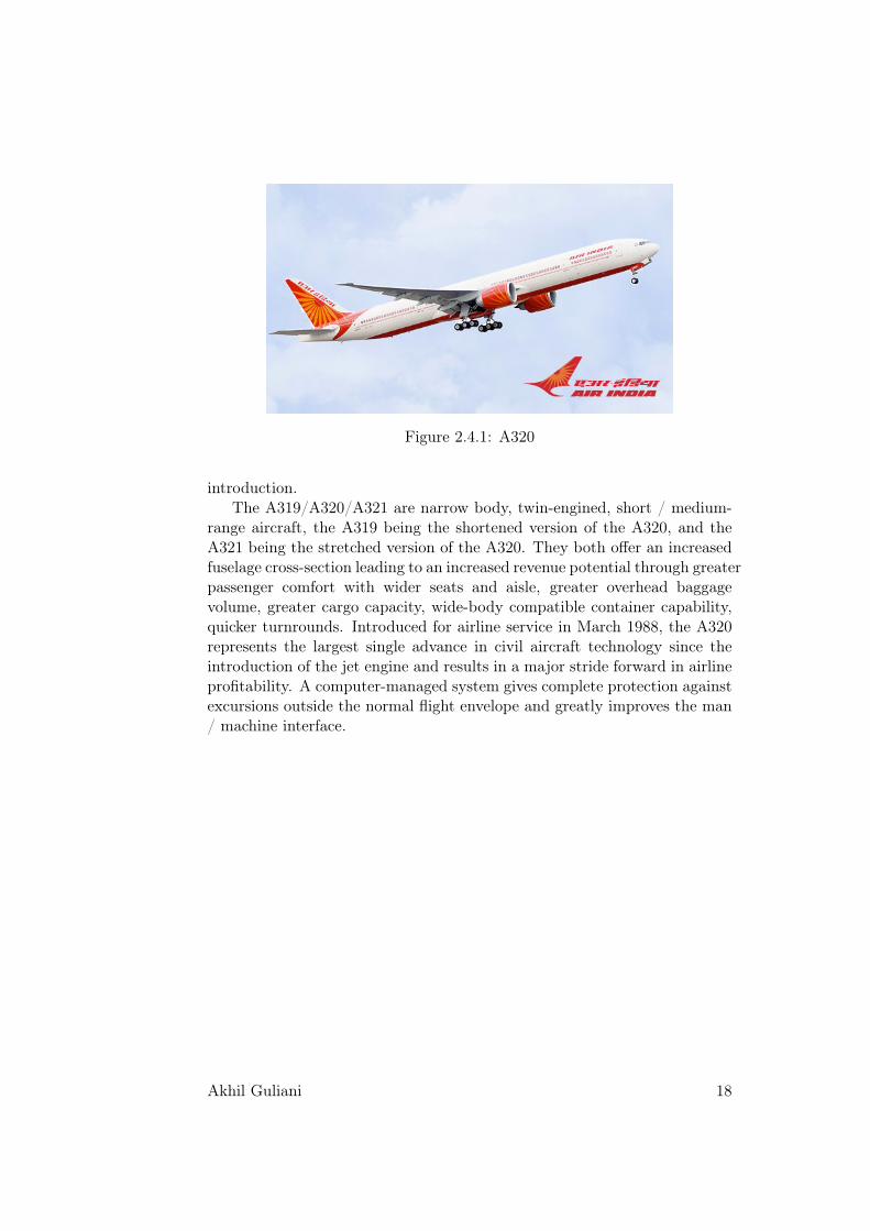
Figure 2.4.1: A320
introduction.The A319/A320/A321 are narrow body, twin-engined, short / medium-
range aircraft, the A319 being the shortened version of the A320, and theA321 being the stretched version of the A320. They both offer an increasedfuselage cross-section leading to an increased revenue potential through greaterpassenger comfort with wider seats and aisle, greater overhead baggagevolume, greater cargo capacity, wide-body compatible container capability,quicker turnrounds. Introduced for airline service in March 1988, the A320represents the largest single advance in civil aircraft technology since theintroduction of the jet engine and results in a major stride forward in airlineprofitability. A computer-managed system gives complete protection againstexcursions outside the normal flight envelope and greatly improves the man/ machine interface.
Akhil Guliani 18

Chapter 3
Instrument Shop
3.1 Introduction
Aircraft Instrumentation – Any electronic or mechanically-based instrumentor instrument system designed for detecting, measuring, displaying, record-ing, telemetering, processing, or analyzing different values or quantities en-countered in the flight of an aircraft; often supporting the general control ofthe aircraft.
The instrumentation systems used in aircrafts are the eyes and ears ofthe pilot. they help him navigate the airways safely and efficiently. Thearray of instruments used on an aircraft also help in indicating the status ofthe various measures of an aircraft from the basic fuel indicators to the ultraadvanced systems which check for suggest preventive mainteance measuresin case of system failure under any situation.
Figure 3.1.1: A Generalized Instrumentation system used in Aviation
3.2 Observations
The instrument shop had a huge variety of instruments being repaired andmaintined. I was able to get a basic understanding of what is aviation andthe role of Instrumentation in Aircraft safety and operation. The followingare some Instruments I was able to observe and learn about in detail.
3.2.1 Laser gyros
A ring laser gyro splits a beam of laser light into two beams in oppositedirections through narrow tunnels in a closed optical circular path aroundthe perimeter of a triangular block of temperature-stable Cervit glass withreflecting mirrors placed in each corner. When the gyro is rotating at some
19

angular rate, the distance traveled by each beam becomes different—theshorter path being opposite to the rotation. The phase-shift between thetwo beams can be measured by an interferometer, and is proportional to therate of rotation (Sagnac effect).
In practice, at low rotation rates the output frequency can drop to zeroafter the result of back scattering causing the beams to synchronize and locktogether. This is known as a lock-in, or laser-lock. The result is that there isno change in the interference pattern, and therefore no measurement change.
To unlock the counter-rotating light beams, laser gyros either have inde-pendent light paths for the two directions (usually in fiber optic gyros), orthe laser gyro is mounted on a piezo-electric dither motor that rapidly vi-brates the laser ring back and forth about its input axis through the lock-inregion to decouple the light waves.
The shaker is the most accurate, because both light beams use exactlythe same path. Thus laser gyros retain moving parts, but they do not moveas far.
3.2.2 Attitude Indicator (Artificial Horizon)
An attitude indicator (AI), also known as gyro horizon or artificial horizon,is an instrument used in an aircraft to inform the pilot of the orientation ofthe aircraft relative to earth. It indicates pitch (fore and aft tilt) and bankor roll (side to side tilt) and is a primary instrument for flight in instrumentmeteorological conditions.
The essential components of the indicator are:
1. "miniature wings", horizontal lines with a dot between them represent-ing the actual wings and nose of the aircraft. the center horizon barseparating the two halves of the display, with the top half usually bluein color to represent sky and the bottom half usually dark to representearth.
2. degree marks representing the bank angle. They run along the rim ofthe dial. On a typical indicator, the first 3 marks on both sides of thecenter mark are 10 degrees apart. The next is 60 degrees and the markin the middle of the dial is 90 degrees.
If the symbolic aircraft dot is above the horizon line (blue background)the aircraft is nose up. If the symbolic aircraft dot is below the horizon line(brown background) the aircraft is nose down. When the dot and wings areon the horizon line, the aircraft is in level flight.
3.2.3 Flight Recorders
A flight recorder is an electronic recording device placed in an aircraft for thepurpose of facilitating the investigation of an aircraft accident or incident.
Akhil Guliani 20

Figure 3.2.1: Attitude Indicator
For this reason, flight recorders are required to be capable of surviving theconditions likely to be encountered in a severe aircraft accident. They aretypically specified to withstand an impact of 3400 g and temperatures ofover 1,000 °C (1,832 °F) (as required by EUROCAE ED-112). There aretwo common types of flight recorder, the flight data recorder (FDR) andthe cockpit voice recorder (CVR). In some cases, the two recorders may becombined in a single FDR/CVR unit.
Figure 3.2.2: FDR
Since the 1970s most large civil jet transports have been additionallyequipped with a "quick access recorder" (QAR). This records data on a re-movable storage medium. Access to the FDR and CVR is necessarily difficultbecause of the requirement that they survive an accident. They also requirespecialized equipment to read the recording. The QAR recording mediumis readily removable and is designed to be read by equipment attached toa standard desktop computer. In many airlines the quick access recordingsare scanned for ’events’, an event being a significant deviation from normaloperational parameters. This allows operational problems to be detectedand eliminated before an accident or incident results.
Akhil Guliani 21

Many modern aircraft systems are digital or digitally controlled. Veryoften the digital system will include Built-In Test Equipment which recordsinformation about the operation of the system. This information may alsobe accessed to assist with the investigation of an accident or incident.
3.2.4 Altimeter
An altimeter is an instrument used to measure the altitude of an objectabove a fixed level. The altitude of most aircraft is determined based on themeasurement of atmospheric pressure. The greater the altitude the lowerthe pressure. In it, an aneroid barometer measures the atmospheric pressurefrom a static port outside the aircraft. Air pressure decreases with an increaseof altitude—approximately 100 hectopascals per 800 meters or one inch ofmercury per 1000 feet near sea level.
Figure 3.2.3: Internal View of an Aneroid Altimeter
The aneroid altimeter is calibrated to show the pressure directly as analtitude above mean sea level, in accordance with a mathematical modeldefined by the International Standard Atmosphere (ISA).
3.2.5 Air Speed Indicator
The airspeed indicator or airspeed gauge is an instrument used in an aircraftto display the craft’s airspeed, typically in knots, to the pilot. The airspeedindicator is used by the pilot during all phases of flight, from take-off, climb,cruise, descent and landing in order to maintain airspeeds specific to theaircraft type and operating conditions as specified in the Operating Man-ual. During instrument flight, the airspeed indicator is used in addition tothe Artificial horizon as an instrument of reference for pitch control duringclimbs, descents and turns.
Akhil Guliani 22

Figure 3.2.4: Internal View of an Air Speed Indicator
Airspeed indicators work by measuring the difference between static pres-sure, captured through one or more static ports; and stagnation pressure dueto "ram air", captured through a pitot tube. This difference in pressure dueto ram air is called impact pressure.
3.2.6 Primary Flight Display
A primary flight display or PFD is a modern aircraft instrument dedicated toflight information. Much like multi-function displays, primary flight displaysare built around an LCD or CRT display device. Representations of older sixpack or "steam gauge" instruments are combined on one compact display,simplifying pilot workflow and streamlining cockpit layouts. Most airlinersbuilt since the 1980s — as well as many business jets and an increasingnumber of newer general aviation aircraft — have glass cockpits equippedwith primary flight and multi-function displays. Mechanical gauges have notbeen completely eliminated from the cockpit with the onset of the PFD; theyare retained for backup purposes in the event of total electrical failure.
Figure 3.2.5: PFD
While the PFD does not directly use the pitot-static system to physicallydisplay flight data, it still uses the system to make altitude, airspeed, vertical
Akhil Guliani 23

speed, and other measurements precisely using air pressure and barometricreadings. An air data computer analyzes the information and displays it tothe pilot in a readable format. A failure of a PFD deprives the pilot of anextremely important source of information. While backup instruments willstill provide the most essential information, they may be spread over severallocations in the cockpit, which must be scanned by the pilot, whereas thePFD presents all this information on one display.
Akhil Guliani 24
Chapter 4
Radio Shop
4.1 Introduction
The Radio Shop at Air India was responsible for the upkeep of Communi-cation and navigational instruments used in the Airbus A-320. During myposting at the workshop I was able to observe numerous of these equipmentssuch as the radar, microphones and other navigational aids usch as ILS,VOR, radio altimeter,etc. These are disscused in the sections to follow.
4.2 Communication Systems in Aviation
4.2.1 Introduction
Communication systems are an essential part of any organizational systemwhere coordination of any scale is required. The aviation industry in byfar the most coordinated operation in the world, which makes the commu-nication channels used in the industry its backbone. The communicationsbetween airplane and ground stations are genrally done using VHF rangeradio equipmen when within150-200 Km of the station and HF otherwise.Generally, VHF is the prefered band for communication beacuase of moreprecision in message delivery than HF. The following sections disscuss thetwo dominant communication systems in the industry in breif.
4.2.2 VHF
Very high frequency (VHF) is the radio frequency range from 30 MHz to 300MHz. Frequencies immediately below VHF are denoted high frequency (HF),and the next higher frequencies are known as ultra high frequency (UHF).Common uses for VHF are FM radio broadcast, television broadcast, landmobile stations (emergency, business, private use and military), long rangedata communication with radio modems, amateur radio, marine communi-
25

cations, air traffic control communications and air navigation systems (e.g.VOR, DME & ILS).
VHF propagation characteristics are ideal for short-distance terrestrialcommunication, with a range generally somewhat farther than line-of-sightfrom the transmitter (see formula below). Unlike high frequencies (HF), theionosphere does not usually reflect VHF radio and thus transmissions arerestricted to the local area (and don’t interfere with transmissions thousandsof kilometres away). VHF is also less affected by atmospheric noise andinterference from electrical equipment than lower frequencies. Whilst it ismore easily blocked by land features than HF and lower frequencies, it is lessaffected by buildings and other less substantial objects than UHF frequencies.
The VHF aviation communication system works on the airband of 118.000MHz to 136.975 MHz. Each channel is spaced from the adjacent ones by 8.33kHz. VHF is also used for line of sight communication such as aircraft-to-aircraft and aircraft-to-ATC. Amplitude modulation (AM) is used, and theconversation is performed in simplex mode.
4.2.3 HF
High frequency (HF) radio frequencies are between 3 and 30 MHz. Alsoknown as the decameter band or decameter wave as the wavelengths rangefrom one to ten decameters (ten to one hundred metres). Frequencies imme-diately below HF are denoted Medium-frequency (MF), and the next higherfrequencies are known as Very high frequency (VHF). The Shortwave range(2.310 - 25.820 MHz) used by international broadcasters is part of the HFfrequency spectrum. In aviation virtually the entire spectrum (2 - 30 MHz) isused for HF communications. The ionosphere often refracts HF radio wavesquite well. This phenomenon is known as skywave propagation. Becauseof these characteristics this range is extensively used for medium and longrange radio communication.
4.2.4 Cockpit voice recorder
A cockpit voice recorder (CVR), often referred to as a "black box",[1] is aflight recorder used to record the audio environment in the flight deck of anaircraft for the purpose of investigation of accidents and incidents. This istypically achieved by recording the signals of the microphones and earphonesof the pilots headsets and of an area microphone in the roof of the cockpit. Astandard CVR is capable of recording 4 channels of audio data for a period of2 hours. The original requirement was for a CVR to record for 30 minutes,but this has been found to be insufficient in many cases, significant partsof the audio data needed for a subsequent investigation having occurredmore than 30 minutes before the end of the recording.the CVR is typicallymounted in the tail section (the empennage) of an airplane to maximize the
Akhil Guliani 26
likelihood of its survival in a crash.
4.3 Navigation systems in Aviation
4.3.1 Introduction
Navigation is the determination of position and direction on or above thesurface of the Earth. Navigation systems may be entirely on board a vehicleor vessel, or they may be located elsewhere and communicate via radio orother signals with a vehicle or vessel, or they may use a combination of thesemethods. Navigation systems are capable of:
1. containing maps, which may be displayed in human readable formatvia text or in a graphical format
2. determining a aircrafts’s location via sensors, maps, or informationfrom external sources
3. providing suggested directions to the pilot
4. providing directions directly to the autopilot sub system
5. providing information on nearby aircrafts, or other hazards or obstacles
6. providing information on traffic conditions and suggesting alternativedirections
Avionics can use satellite-based systems (such as GPS and WAAS), ground-based systems (such as VOR or ILS), or any combination thereof. Navigationsystems calculate the position automatically and display it to the flight crewon moving map displays.
The following sub-sections disscuss a few navigational aids used in avia-tion.
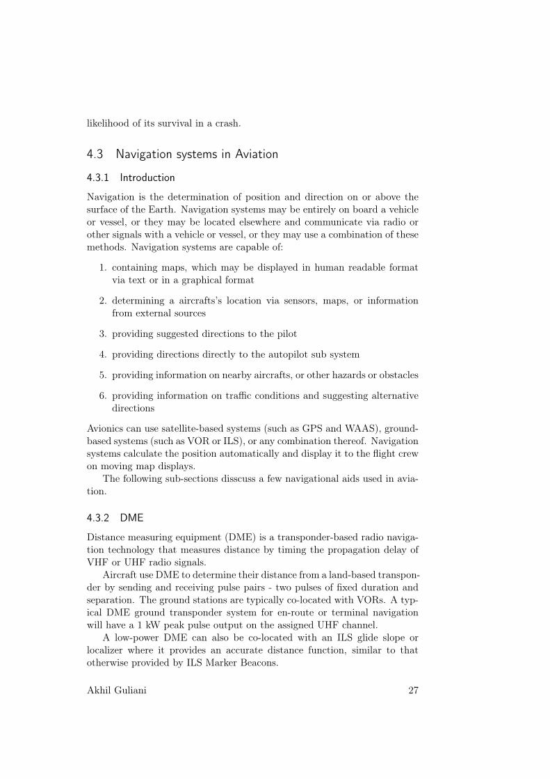
4.3.2 DME
Distance measuring equipment (DME) is a transponder-based radio naviga-tion technology that measures distance by timing the propagation delay ofVHF or UHF radio signals.
Aircraft use DME to determine their distance from a land-based transpon-der by sending and receiving pulse pairs - two pulses of fixed duration andseparation. The ground stations are typically co-located with VORs. A typ-ical DME ground transponder system for en-route or terminal navigationwill have a 1 kW peak pulse output on the assigned UHF channel.
A low-power DME can also be co-located with an ILS glide slope orlocalizer where it provides an accurate distance function, similar to thatotherwise provided by ILS Marker Beacons.
Akhil Guliani 27

The DME system is composed of a UHF transmitter/receiver (interroga-tor) in the aircraft and a UHF receiver/transmitter (transponder) on theground. A typical DME transponder can provide distance information to100 aircraft at a time. Above this limit the transponder avoids overload bylimiting the gain of the receiver. Replies to weaker more distant interro-gations are ignored to lower the transponder load. The technical term foroverload of a DME station caused by large numbers of aircraft is stationsaturation.
4.3.3 VOR
VOR, short for VHF omnidirectional radio range, is a type of radio navi-gation system for aircraft. A VOR ground station broadcasts a VHF radiocomposite signal including the station’s identifier, voice, and navigation sig-nal. The identifier is typically a two- or three-letter string in Morse code. .The navigation signal allows the airborne receiving equipment to determinea magnetic bearing from the station to the aircraft (direction from the VORstation in relation to the Earth’s magnetic North at the time of installation).VOR stations in areas of magnetic compass unreliability are oriented withrespect to True North. This line of position is called the "radial" from theVOR. The intersection of two radials from different VOR stations on a chartprovides the position of the aircraft.
VORs are assigned radio channels between 108.0 MHz (megahertz) and117.95 MHz (with 50 kHz spacing); this is in the VHF (very high frequency)range. The first 4 MHz is shared with the ILS band. To leave channels forILS, in the range 108.0 to 111.95 MHz, the 100 kHz digit is always even, so108.00, 108.05, 108.20, and so on are VOR frequencies but 108.10, 108.15,108.30, and so on, are reserved for ILS.
The VOR encodes azimuth (lateral direction from the station) as thephase relationship of a reference and a variable signal. The omni-directionalsignal contains a modulated continuous wave (MCW) 7 wpm Morse codestation identifier, and usually contains an amplitude modulated (AM) voicechannel. The conventional 30 Hz reference signal is on a 9960 Hz frequencymodulated (FM) subcarrier. The variable amplitude modulated (AM) signalis conventionally derived from the lighthouse-like rotation of a directional an-tenna array 30 times per second. Although older antennas were mechanicallyrotated, current installations scan electronically to achieve an equivalent re-sult with no moving parts. When the signal is received in the aircraft, thetwo 30 Hz signals are detected and then compared to determine the phaseangle between them. The phase angle by which the AM signal lags the FMsubcarrier signal is equal to the direction from the station to the aircraft, indegrees from local magnetic north, and is called the "radial."
This information is then fed to one of four common types of indicators:
1. An Omni-Bearing Indicator (OBI) is the typical light-airplane VOR
Akhil Guliani 28

indicator and is shown in the accompanying illustration. It consists ofa knob to rotate an "Omni Bearing Selector" (OBS), and the OBS scalearound the outside of the instrument, used to set the desired course.A"course deviation indicator" (CDI) is centered when the aircraft is onthe selected course, or gives left/right steering commands to returnto the course. An "ambiguity" (TO-FROM) indicator shows whetherfollowing the selected course would take the aircraft to, or away fromthe station.
2. A Horizontal Situation Indicator (HSI) is considerably more expensiveand complex than a standard VOR indicator, but combines headinginformation with the navigation display in a much more user-friendlyformat, approximating a simplified moving map.
3. A Radio Magnetic Indicator (RMI), developed previous to the HSI,features a course arrow superimposed on a rotating card which showsthe aircraft’s current heading at the top of the dial. The "tail" of thecourse arrow points at the current radial from the station, and the"head" of the arrow points at the reciprocal (180° different) course tothe station.
4. An Area Navigation (RNAV) system is an onboard computer, withdisplay, and up-to-date navigation database. At least two VOR sta-tions, or one VOR/DME station is required, for the computer to plotaircraft position on a moving map, or display course deviation relativeto a waypoint (virtual VOR station).
4.3.4 ILS
An instrument landing system (ILS) is a ground-based instrument approachsystem that provides precision guidance to an aircraft approaching and land-ing on a runway, using a combination of radio signals and, in many cases,high-intensity lighting arrays to enable a safe landing during instrument me-teorological conditions (IMC), such as low ceilings or reduced visibility dueto fog, rain, or blowing snow.
Instrument approach procedure charts (or approach plates) are publishedfor each ILS approach, providing pilots with the needed information to fly anILS approach during instrument flight rules (IFR) operations, including theradio frequencies used by the ILS components or navaids and the minimumvisibility requirements prescribed for the specific approach.
Radio-navigation aids must keep a certain degree of accuracy (set byinternational standards of CAST/ICAO); to assure this is the case, flightinspection organizations periodically check critical parameters with properlyequipped aircraft to calibrate and certify ILS precision.
Akhil Guliani 29

the ILS, follows two signals: a localizer for lateral guidance (VHF); anda glide slope for vertical guidance (UHF). When Navigation receiver is tunedto a localizer frequency a second receiver, the glide-slope receiver, is auto-matically tuned to its proper frequency. The pairing is automatic. They areexplained as follows:
Figure 4.3.1: ILS Sketch
1. Localizer : The localizer signal provides lateral information to guidethe aircraft to the centerline of the runway. It is similar to a VORsignal except that it provides radial information for only a single course;the runway heading. Localizer information is displayed on the sameindicator as the VOR information.
2. Glide Slope: The Glide Slope is the signal that provides vertical guid-ance to the aircraft during the ILS approach. The standard glide-slopepath is 3° downhill to the approach-end of the runway. Follow it faith-fully and your altitude will be precisely correct when you reach thetouchdown zone of the runway.
3. Marker Beacons : Marker beacons are used to alert the pilot that anaction (e.g., altitude check) is needed. This information is presented tothe pilot by audio and visual cues. The ILS may contain three markerbeacons: inner, middle and outer. The inner marker is used only forCategory II operations. The marker beacons are located at specifiedintervals along the ILS approach and are identified by discrete audioand visual characteristics.
4.3.5 Radar
Radar is an object-detection system which uses radio waves to determinethe range, altitude, direction, or speed of objects. The name RADARis acontraction of the words RAdio Detection And Ranging. It can be used todetect aircraft, motor vehicles, weather formations, and terrain. The radardish or antenna transmits pulses of radio waves or microwaves which bounce
Akhil Guliani 30
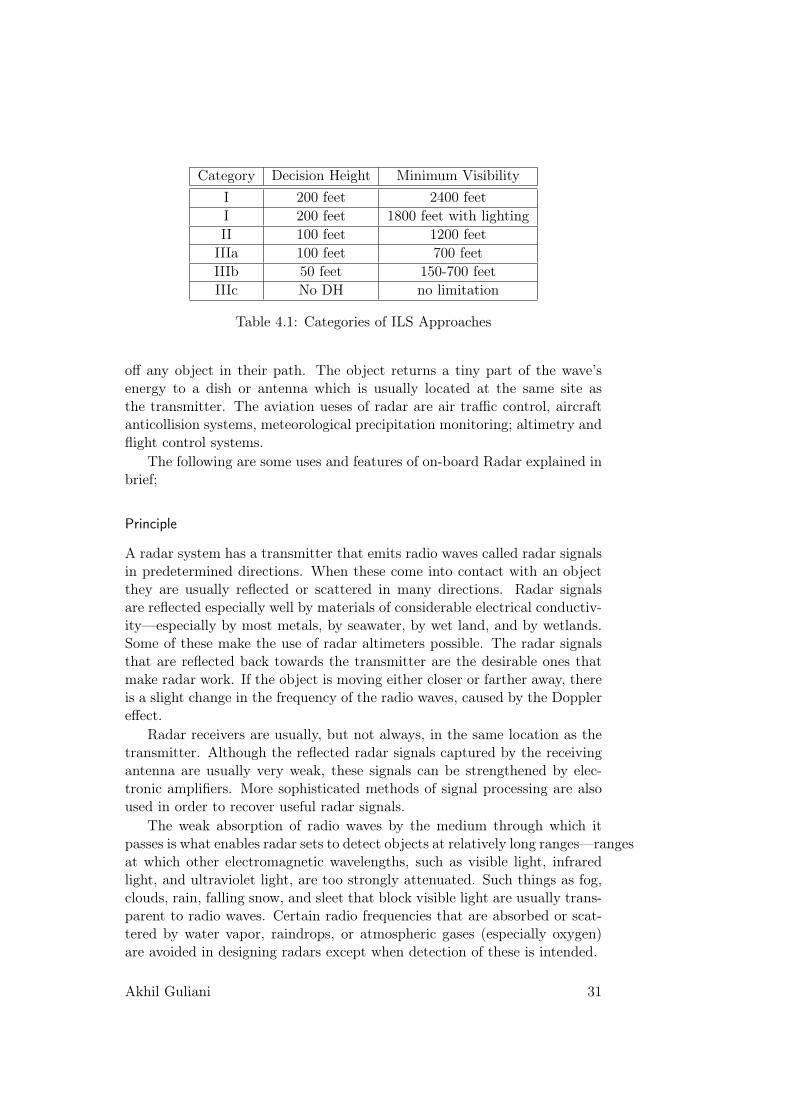
Category Decision Height Minimum VisibilityI 200 feet 2400 feetI 200 feet 1800 feet with lightingII 100 feet 1200 feetIIIa 100 feet 700 feetIIIb 50 feet 150-700 feetIIIc No DH no limitation
Table 4.1: Categories of ILS Approaches
off any object in their path. The object returns a tiny part of the wave’senergy to a dish or antenna which is usually located at the same site asthe transmitter. The aviation ueses of radar are air traffic control, aircraftanticollision systems, meteorological precipitation monitoring; altimetry andflight control systems.
The following are some uses and features of on-board Radar explained inbrief;
Principle
A radar system has a transmitter that emits radio waves called radar signalsin predetermined directions. When these come into contact with an objectthey are usually reflected or scattered in many directions. Radar signalsare reflected especially well by materials of considerable electrical conductiv-ity—especially by most metals, by seawater, by wet land, and by wetlands.Some of these make the use of radar altimeters possible. The radar signalsthat are reflected back towards the transmitter are the desirable ones thatmake radar work. If the object is moving either closer or farther away, thereis a slight change in the frequency of the radio waves, caused by the Dopplereffect.
Radar receivers are usually, but not always, in the same location as thetransmitter. Although the reflected radar signals captured by the receivingantenna are usually very weak, these signals can be strengthened by elec-tronic amplifiers. More sophisticated methods of signal processing are alsoused in order to recover useful radar signals.
The weak absorption of radio waves by the medium through which itpasses is what enables radar sets to detect objects at relatively long ranges—rangesat which other electromagnetic wavelengths, such as visible light, infraredlight, and ultraviolet light, are too strongly attenuated. Such things as fog,clouds, rain, falling snow, and sleet that block visible light are usually trans-parent to radio waves. Certain radio frequencies that are absorbed or scat-tered by water vapor, raindrops, or atmospheric gases (especially oxygen)are avoided in designing radars except when detection of these is intended.
Akhil Guliani 31

Figure 4.3.2: Block Diagram of RADAR
Components
A radar’s major components are:
1. A transmitter that generates the radio signal with an oscillator such asa klystron or a magnetron and controls its duration by a modulator.
2. A waveguide that links the transmitter and the antenna.
3. A duplexer that serves as a switch between the antenna and the trans-mitter or the receiver for the signal when the antenna is used in bothsituations.
4. A receiver. Knowing the shape of the desired received signal (a pulse),an optimal receiver can be designed using a matched filter.
5. An Antenna. A parab
6. An electronic section that controls all those devices and the antennato perform the radar scan ordered by software.
7. A link to the Navigational Display Unit.
Applications
The major applications of radar in aviation are as follows:
1. Plan Position Indicator (PPI) : The plan position indicator (PPI), isthe most common type of radar display. The radar antenna is usuallyrepresented in the center of the display, so the distance from it andheight above ground can be drawn as concentric circles. As the radarantenna rotates, a radial trace on the PPI sweeps in unison with itabout the center point.
Akhil Guliani 32

2. Weather Indicator: Weather systems such as weather radar are impor-tant for aircraft flying at night or in instrument meteorological condi-tions, where it is not possible for pilots to see the weather ahead. Heavyprecipitation (as sensed by radar) or severe turbulence (as sensed bylightning activity) are both indications of strong convective activityand severe turbulence, and weather systems allow pilots to deviatearound these areas.
3. Radar altimeter : The radar altimeter is a more high-tech altimeterwhich uses radar to detect the plane’s altitude. This type of altimeteris not affected by differences in air pressure, because it does not mea-sure air pressure at all. It measures your true altitude above whateverterrain you are currently flying over. Rather than measuring altitudeASL, it measures altitude AGL (Above Ground Level). A radar altime-ter is highly accurate and thus of extreme importance to any airplanepilot. Unfortunately, many smaller civilian aircraft still do not haveone, instead relying on a pressure-based altimeter.
Akhil Guliani 33

Chapter 5
ATEC Shop
5.1 Introduction
The ATEC shop is named after the ATEC series of computers, which areplaced within the shop. Air India has two ATEC’s a Series 5 and a Series 6.Togather both of these can test all the computers used in the Airbus A-320Family of Aircrafts. During my posting at the shop I was able to observe andlearn about componenet testing procedures and get an overveiw of the roleof computers in modern aircrafts. the following sections give a brief accountof those observations.
5.2 Equipment Testing
5.2.1 ATEC
ATEC, is a general purpose automatic test system that has been used for
Figure 5.2.1: ATEC series 6
more than 30 years to support commercial airliners, as well as military air-craft, helicopters and ground vehicles. It is the world’s leading test solution
34

for Airbus and Boeing jetliners – utilized by some 160 organizations world-wide, including airlines, original equipment manufacturers, and MRO (main-tenance, repair and overhaul) service providers. The latest model avialable,ATEC Series 6 VXI-based automatic test equipment, provides all of the re-sources and technologies required to test the latest-generation avionics onAirbus A320s, A330s, A340s and A380s, as well as later model Boeing 737sand the 777.
The ATEC Series 6 is used for maintenance testing of every major equip-ment family: flight control systems, primary and secondary flight displays,engine control systems, fuel monitoring systems, landing/brake control sys-tems, auxiliary power units and new generation avionics.
Figure 5.2.2: ATEC Modular architecture
The ATEC Series 6 is fully compliant with international norms and stan-dards. It is designed as a modular architecture using off-the-shelf resourcesand is available in different configurations adapted to users’ needs.
5.2.2 Procedure
The Components which have been serviced or have reached their periodiccheck limit are tested as follows :
1. First the component is cleaned and it is made sure that no dust or rustis present on or in the component connectors.
2. Then the components testbench is attached to the ATEC Station.
3. Then the ATEC computer is used to configure the station for the par-ticular testbench.
4. A self test for the testbench is performed to confirm its servicability.
5. After the selftest the component is conected to the testbench.
6. Once the connections are tested the test procedure is initiated.
7. The test may take upto24 hours for completion depending upon thetype of equipment and level of testing.
Akhil Guliani 35

8. On completion of the test a report is generated detailing all the faultsdetected in the equipment, if any.
9. The test report is attached to the Service sheet of the equipment andall necessary paperwork is updated.
10. finally the component is dispatched to the relevant servicing shop, iffaulty. Else it is sent to the store.
Akhil Guliani 36

Bibliography
1. Component Service Manuals, reveant Manufacturer.
2. FAA Pilot Handbook
3. www.airindia.in, Air India Website
37

Appendix A
About the Internship
A.1 Introduction
Air India’s Engineering division’s Engineering Training School, New Delhioffers undergraduate students an opportunity to work and observe the on-going maintenance, repair and overhaul(MRO) process at their hangers andworkshop at the IGI Airport, New Delhi. During the Internship the intern isposted at various workshops in accordance to his engineering trade and fieldof interest. The internship opportunity at Air India’s Engineering divisionis one of the best places in the country to enhance one’s knowledge aboutaviation and aircrafts.
Figure A.1.1: Air India Logo
A.2 About Air India
Air India is India’s national flag carrier. Although air transport was bornin India on February 18, 1911 when Henri Piquet, flying a Humber bi-plane,carried mail from Allahabad to Naini Junction, some six miles away, thescheduled services in India, in the real sense, began on October 15, 1932. Itwas on this day that J.R.D. Tata, the father of Civil Aviation in India andfounder of Air India, took off from Drigh Road Airport, Karachi, in a tiny,light single-engined de Havilland Puss Moth on his flight to Mumbai (thenknown as Bombay) via Ahmedabad.
38

Air India is largest operating commercial airline in India. Air India oper-ates nearly (get number form internet) flights daily; making its engineeringdivision of the most critical departments to ensure proper functioning ofthe fleet. Having three regional centers; in New Delhi, Mumbai, Calcuttaand Chennai; for overhaul and maintenance of popular aircrafts such as theAirbus A-320 series and the Boeing 737 series has made the Engineering de-partment one of the most experienced and sought after aircraft maintenancecrews in the country.
Aircraft Type Fleet SizeWide Body Aircrafts: 27
B777-200LR 8B777-300ER 12B747-400 5A330-200 2
Narrow Body Aircrafts: 94B-737-800(AIX) 21
A320 18A319 24A321 20
CRJ-700 4ATR42 7
Total Fleet Size: 121
Table A.1: Air India Fleet details
Air India has major infrastructure in Mumbai and Delhi, with 5,610skilled engineers and technicians capable of undertaking maintenance of allaircraft and engines currently in its fleet. There are in addition three moremajor ports at Chennai, Kolkata, Hyderabad and Bangaluru.
Akhil Guliani 39

Appendix B
ESDS : Electro-Static DischargeSensitive Devices
B.1 Introduction
An electrostatic-sensitive device (often abbreviated ESD) is any component(primarily electrical) which can be damaged by common static charges whichbuild up on people, tools, and other non-conductors or semiconductors. ESDcommonly also stands for electrostatic discharge.
Figure B.1.1: ESDS Warning Label
Electrostatic discharge is a serious issue in solid state electronics, such asintegrated circuits. Integrated circuits are made from semiconductor materi-als such as silicon and insulating materials such as silicon dioxide. Either ofthese materials can suffer permanent damage when subjected to high volt-ages; as a result, there are now a number of antistatic devices that helpprevent static build up.
B.2 Causes of ESD
One of the causes of ESD events is static electricity. Static electricity isoften generated through turbocharging, the separation of electric chargesthat occurs when two materials are brought into contact and then separated.Examples of turbocharging include walking on a rug, rubbing a plastic combagainst dry hair, rubbing a balloon against a sweater, ascending from a fabriccar seat, or removing some types of plastic packaging. In all these cases,the friction between two materials results in turbocharging, thus creating adifference of electrical potential that can lead to an ESD event.
40
Another cause of ESD damage is through electrostatic induction. Thisoccurs when an electrically charged object is placed near a conductive objectisolated from ground. The presence of the charged object creates an electro-static field that causes electrical charges on the surface of the other objectto redistribute. Even though the net electrostatic charge of the object hasnot changed, it now has regions of excess positive and negative charges. AnESD event may occur when the object comes into contact with a conductivepath. For example, charged regions on the surfaces of styrofoam cups or bagscan induce potential on nearby ESD sensitive components via electrostaticinduction and an ESD event may occur if the component is touched with ametallic tool.
B.3 Safety precautions while handling ESDS components
The preventive measures for ESD are based on an Electrostatic ProtectiveArea (EPA). The EPA can be a small working station or a large manufactur-ing area. The principle behind an EPA is that there are no highly chargingmaterials in the vicinity of ESD sensitive electronics, all conductive materialsare grounded, workers are grounded, and charge build-up on ESD sensitiveelectronics is prevented. The International standards used to define typicalEPA are provided by International Electrotechnical Commission (IEC) orAmerican National Standards Institute (ANSI). The standards used at AirIndia are specified as follows:
B.3.1 Identification
• There is a yellow Label on Component/Packing
• The component is wrapped in static protecting pink poly-packing
B.3.2 Dont’s for handling
• Donot touch the component directly. Touch the metal rack first.
• Donot touch the connectors and pins by hand.
• Donot use hydraulic fluid spilled bag/package for packing.
• Donot bring the component in contact with any object which may havestatic charge.
• Donot use ordinary plastic and Styrofoam in proximity of ESDS de-vices.
• Donot use ordinary adhesive tapes on ESDS devices.
Akhil Guliani 41

B.3.3 Do’s for handling
• Touch metal rack first so that static charge on your body is discharged.
• ESDS units must be stored/placed only on anti-static sheets.
• Unserviceable units must be handled with same care a serviceable ones.
• Blanking of all connectors should be done before handling ESDS units.
• Packing material and boxes used foe serviceable units should be reusedon unserviceable units removed from the aircraft.
• ESDS components should be issued with boxes and packing.
• Transportation trollies should have cushion on the bottom to avoiddamages to the component due to jerks.
B.3.4 Advantages of proper handling
• Reduced damage to the component.
• Reduced down-time and savings on repair of components.
• Improved technical reliability.
Akhil Guliani 42

Appendix C
Cockpit overveiw
C.1 Introduction
A cockpit or flight deck is the area, usually near the front of an aircraft,from which a pilot controls the aircraft. The cockpit of an aircraft containsflight instruments on an instrument panel, and the controls which enable thepilot to fly the aircraft. Most modern cockpits are enclosed, except on somesmall aircraft, and cockpits on large airliners are also physically separatedfrom the cabin. From the cockpit an aircraft is controlled on the groundand in the air. Cockpit as a term for the pilot’s compartment in an aircraftfirst appeared in 1914. Most Airbus cockpits are computerised glass cockpitsfeaturing fly-by-wire technology. The control column has been replaced withan electronic sidestick.
The following sections give an overvew of the instruments present in acockpit and the egrnomics of its design.
C.2 Cockpit Layout
Ergonomics and human factors concerns are important in the design of mod-ern cockpits. The layout and function of cockpit displays controls are de-signed to increase pilot situation awareness without causing information over-load. The layout of control panels in modern airliners has become largelyunified across the industry. The majority of the systems-related controls(such as electrical, fuel, hydraulics and pressurization) for example, are usu-ally located in the ceiling on an overhead panel. Radios are generally placedon a panel between the pilot’s seats known as the pedestal. Automatic flightcontrols such as the autopilot are usually placed just below the windscreenand above the main instrument panel on the glareshield. A central conceptin the design of the cockpit is the Design Eye Position or "DEP", from whichpoint all displays should be visible.
43
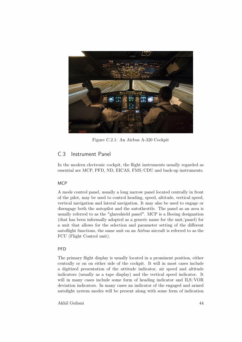
Figure C.2.1: An Airbus A-320 Cockpit
C.3 Instrument Panel
In the modern electronic cockpit, the flight instruments usually regarded asessential are MCP, PFD, ND, EICAS, FMS/CDU and back-up instruments.
MCP
A mode control panel, usually a long narrow panel located centrally in frontof the pilot, may be used to control heading, speed, altitude, vertical speed,vertical navigation and lateral navigation. It may also be used to engage ordisengage both the autopilot and the autothrottle. The panel as an area isusually referred to as the "glareshield panel". MCP is a Boeing designation(that has been informally adopted as a generic name for the unit/panel) fora unit that allows for the selection and parameter setting of the differentautoflight functions, the same unit on an Airbus aircraft is referred to as theFCU (Flight Control unit).
PFD
The primary flight display is usually located in a prominent position, eithercentrally or on on either side of the cockpit. It will in most cases includea digitized presentation of the attitude indicator, air speed and altitudeindicators (usually as a tape display) and the vertical speed indicator. Itwill in many cases include some form of heading indicator and ILS/VORdeviation indicators. In many cases an indicator of the engaged and armedautofight system modes will be present along with some form of indication
Akhil Guliani 44

of the selected values for altitude, speed, vertical speed and heading. It maybe pilot selectable to swap with the ND.
ND
A navigation display, which may be adjacent to the PFD, shows the currentroute and information on the next waypoint, current wind speed and winddirection. It may be pilot selectable to swap with the PFD.
EICAS/ECAM
The Engine Indication and Crew Alerting System (used for Boeing) or Elec-tronic Centralized Aircraft Monitor (for Airbus) will allow the pilot to mon-itor the following information: values for N1, N2 and N3, fuel temperature,fuel flow, the electrical system, cockpit or cabin temperature and pressure,control surfaces and so on. The pilot may select display of information bymeans of button press.
FMS
The flight management system/control unit may be used by the pilot toenter and check for the following information: flight plan, speed control,navigation control, and so on.
Back-up instruments
In a less prominent part of the cockpit, in case of failure of the other in-struments, there will be a set of back-up instruments, showing basic flightinformation such as speed, altitude, heading, and aircraft attitude.
Akhil Guliani 45

Appendix D
Author Profile
46