Industrial ducting - Formula Air
110
Industrial ducting
-
Upload
khangminh22 -
Category
Documents
-
view
2 -
download
0
Transcript of Industrial ducting - Formula Air

Industrial ducting

TAB1 | Industrial ducting Ver. V2 | 23-08-16
Laser welded pipesLongitudinally laser welded pipes with a sheet thickness of 0.75 up to 1.25 mm.This range has been developed to resist to 500 H²O under-pressure (5.000 Pa), see separate resistance chart.
MaterialSendzimir galvanized.
TypeRolled sheets with 6 mm edges for lock rings.
Options• Other types of edges or connections, see Tab 14 ‘edges and
connections'• Other lengths• Other diameters• Sheet thickness up to 3 mm, depending on length and diameter
* with flanges as of Ø700
Laser welded pipes 0.5 m
Ø d Code L s Weightmm mm mm kg80 AA05080 490 0.75 0.75100 AA05100 490 0.75 0.94120 AA05120 490 0.75 1.13125 AA05125 490 0.75 1.18140 AA05140 490 0.75 1.32150 AA05150 490 0.75 1.41160 AA05160 490 0.75 1.51180 AA05180 490 0.75 1.70200 AA05200 490 0.75 1.88220 AA05220 490 0.75 2.04225 AA05225 490 0.75 2.12250 AA05250 490 0.75 2.36275 AA05275 490 0.75 2.59280 AA05280 490 0.75 2.63300 AA05300 490 0.75 2.83315 AA05315 490 0.88 3.49350 AA05350 490 0.88 3.87355 AA05355 490 0.88 4.00400 AA05400 490 0.88 4.42450 AA05450 490 0.88 4.98500 AA05500 490 0.88 5.53550 AA05550 490 1.00 6.91560 AA05560 490 1.00 7.03600 AA05600 490 1.00 7.54630 AA05630 490 1.00 7.92650 AA05650 490 1.00 8.17700* AA05700 490 1.00 15.86710* AA05710 490 1.00 16.20750* AA05750 490 1.00 18.47800* AA05800 490 1.00 20.23850* AA05850 490 1.00 21.50900* AA05900 490 1.00 22.77950* AA05950 490 1.25 27.671000* AA05M10 490 1.25 29.09

TAB1 | Industrial ducting Ver. V2 | 30-01-15
Inspection pipesInspection pipes are longitudinally spot-welded or welded with a stitch-welder.The inspection door is always produced with an inner plate for a smooth inner surface of the pipe.
MaterialSendzimir galvanized.
TypeRolled sheet, including locking mechanism and hinge.
Options• Other lengths• Other diameters• Other sheet thicknesses• Other types of edges or connections, see Tab 14 ‘edges and
connections'
Inspection pipes
Ø d Code s L 500 Opening Weightmm mm mm A x B kg80 AA05080-I 0.75 490 60x190 0.88100 AA05100-I 0.75 490 60x190 1.11120 AA05120-I 0.75 490 100x150 1.33125 AA05125-I 0.75 490 100x150 1.38140 AA05140-I 0.75 490 100x150 1.55150 AA05150-I 0.75 490 100x150 1.66160 AA05160-I 0.75 490 100x150 1.77180 AA05180-I 0.75 490 100x150 1.99200 AA05200-I 0.75 490 100x150 2.21220 AA05220-I 0.75 490 100x150 2.41225 AA05225-I 0.75 490 100x150 2.49250 AA05250-I 0.75 490 100x150 2.76275 AA05275-I 0.75 490 100x150 3.04280 AA05280-I 0.75 490 100x150 3.27300 AA05300-I 0.75 490 100x150 3.32315 AA05315-I 0.75 490 100x150 3.48350 AA05350-I 0.75 490 150x200 3.87355 AA05355-I 0.88 490 150x200 3.92400 AA05400-I 0.88 490 150x200 4.42450 AA05450-I 0.88 490 150x200 4.98500 AA05500-I 0.88 490 150x200 5.53550 AA05550-I 0.88 490 150x200 6.08560 AA05560-I 0.88 490 150x200 6.19600 AA05600-I 0.88 490 150x200 6.64630 AA05630-I 0.88 490 150x200 6.97650 AA05650-I 0.88 490 150x200 7.19700 AA05700-I 0.88 490 150x200 7.74710 AA05710-I 0.88 490 150x200 7.85750 AA05750-I 0.88 490 150x200 8.29800 AA05800-I 0.88 490 150x200 10.05850 AA05850-I 0.88 490 150x200 10.68900 AA05900-I 0.88 490 150x200 11.31950 AA05950-I 0.88 490 150x200 11.941000 AA05M10-I 0.88 490 150x200 12.57

TAB1 | Industrial ducting Ver. V2 | 30-01-15
Telescopic pipesInsert pipes are standard longitudinally welded with a stitch-welder.Composed of a pipe that slides into a standard pipe (to be ordered separately) and a rapid-lock ring for air-tightness.
MaterialSendzimir galvanized.
TypeRolled sheets with a 6 mm edge for lock rings.
Options• Other sheet thicknesses• Other types of edges or connections, see Tab 14 ‘edges and
connections'
DeliveryIncluding a rapid lock ring with rubber insert.
The regulating length is from +20 mm to 450 mm.
Think of airflow direction when installing.
Telescopic pipes
Ø d Code L s Weightmm mm mm kg80 AA05080-T 494 0.75 0.75100 AA05100-T 494 0.75 0.94120 AA05120-T 494 0.75 1.13125 AA05125-T 494 0.75 1.18140 AA05140-T 494 0.75 1.32150 AA05150-T 494 0.75 1.41160 AA05160-T 494 0.75 1.51180 AA05180-T 494 0.75 1.70200 AA05200-T 494 0.75 1.88220 AA05220-T 494 0.75 2.04225 AA05225-T 494 0.75 2.12250 AA05250-T 494 0.75 2.36275 AA05275-T 494 0.75 2.59280 AA05280-T 494 0.75 2.63300 AA05300-T 494 0.75 2.83315 AA05315-T 494 0.75 2.97350 AA05350-T 494 0.75 3.30355 AA05355-T 494 0.75 3.41400 AA05400-T 494 0.88 4.42450 AA05450-T 494 0.88 4.98500 AA05500-T 494 0.88 5.53

TAB1 | Industrial ducting Ver. V2 | 23-08-16
Laser welded pipesLongitudinally laser welded pipes with a sheet thickness of 0.75 up to 1.25 mm.This range has been developed to resist to 500 H²O under-pressure (5.000 Pa), see separate resistance chart.
MaterialSendzimir galvanized.
TypeRolled sheets with 6 mm edges for lock rings.
Options• Other types of edges or connections, see Tab 14 ‘edges and
connections'• Other lengths• Other diameters• Sheet thickness up to 3 mm, depending on length and diameter
* with flanges as of Ø700
Laser welded pipes 1 m
Ø d Code L s Weightmm mm mm kg80 AA10080 990 0.75 1.51100 AA10100 990 0.75 1.88120 AA10120 990 0.75 2.26125 AA10125 990 0.75 2.36140 AA10140 990 0.75 2.64150 AA10150 990 0.75 2.83160 AA10160 990 0.75 3.02180 AA10180 990 0.75 3.39200 AA10200 990 0.75 3.77220 AA10220 990 0.75 4.13225 AA10225 990 0.75 4.24250 AA10250 990 0.75 4.71275 AA10275 990 0.75 5.18280 AA10280 990 0.75 5.27300 AA10300 990 0.75 5.65315 AA10315 990 0.88 6.97350 AA10350 990 0.88 7.74355 AA10355 990 0.88 8.00400 AA10400 990 0.88 8.85450 AA10450 990 0.88 9.95500 AA10500 990 0.88 11.06550 AA10550 990 1.00 13.82560 AA10560 990 1.00 14.06600 AA10600 990 1.00 15.08630 AA10630 990 1.00 15.84650 AA10650 990 1.00 16.34700* AA10700 990 1.00 24.65710* AA10710 990 1.00 25.40750* AA10750 990 1.00 26.77800* AA10800 990 1.00 30.92850* AA10850 990 1.00 32.82900* AA10900 990 1.00 37.72950* AA10950 990 1.25 42.591000* AA10M10 990 1.25 44.81

TAB1 | Industrial ducting Ver. V2 | 30-01-15
Perforated pipesThese are made of metal sheets with 33% perforation. These pipes are longitudinally spot-welded or welded with a stitch-welder.
MaterialSendzimir galvanized with 3 mm holes every 5 mm.
TypeRolled sheets with 6 mm edges for lock rings.
Options• Diameter > Ø 630 mm• Other types of edges or connections, see Tab 14 ‘edges and
connections'
Perforated pipes
Ø d Code L s Weightmm mm mm kg80 AA10080-P 990 1.00 1.35100 AA10100-P 990 1.00 1.69120 AA10120-P 990 1.00 2.02125 AA10125-P 990 1.00 2.11140 AA10140-P 990 1.00 2.36150 AA10150-P 990 1.00 2.52160 AA10160-P 990 1.00 2.70180 AA10180-P 990 1.00 3.03200 AA10200-P 990 1.00 3.37220 AA10220-P 990 1.00 3.69225 AA10225-P 990 1.00 3.79250 AA10250-P 990 1.00 4.21275 AA10275-P 990 1.00 4.63280 AA10280-P 990 1.00 4.71300 AA10300-P 990 1.00 5.05315 AA10315-P 990 1.00 5.31350 AA10350-P 990 1.00 5.90355 AA10355-P 990 1.00 5.98400 AA10400-P 990 1.00 6.74450 AA10450-P 990 1.00 7.58500 AA10500-P 990 1.00 8.42550 AA10550-P 990 1.00 9.26560 AA10560-P 990 1.00 9.42600 AA10600-P 990 1.00 10.10630 AA10630-P 990 1.00 10.61

TAB1 | Industrial ducting Ver. V2 | 23-08-16
Laser welded pipesLongitudinally laser welded pipes with a sheet thickness of 0.75 up to 1.25 mm.This range has been developed to resist to 500 H²O under-pressure (5.000 Pa), see separate resistance chart.
MaterialSendzimir galvanized.
TypeRolled sheets with 6 mm edges for lock rings.
Options• Other types of edges or connections, see Tab 14 ‘edges and
connections'• Other lengths• Other diameters• Sheet thickness up to 3 mm, depending on length and diameter
* with flanges as of Ø700
Laser welded pipes 1.5 m
Ø d Code L s Weightmm mm mm kg500 AA15500 1490 0.88 16.59550 AA15550 1490 1.00 20.73560 AA15560 1490 1.00 21.09600 AA15600 1490 1.00 22.62630 AA15630 1490 1.00 23.76650 AA15650 1490 1.00 24.51700* AA15700 1490 1.00 33.45710* AA15710 1490 1.00 35.10750* AA15750 1490 1.00 38.45800* AA15800 1490 1.00 40.98850* AA15850 1490 1.00 43.50900* AA15900 1490 1.00 46.02950* AA15950 1490 1.25 57.511000* AA15M10 1490 1.25 60.51

TAB1 | Industrial ducting Ver. V2 | 23-08-16
Laser welded pipesLongitudinally laser welded pipes with a sheet thickness of 0.75 up to 1.25 mm.This range has been developed to resist to 500 H²O under-pressure (5.000 Pa), see separate resistance chart.
MaterialSendzimir galvanized.
TypeRolled sheets with 6 mm edges for lock rings.
Options• Other types of edges or connections, see Tab 14 ‘edges and
connections’• Other lengths• Other diameters• Sheet thickness up to 3 mm, depending on length and diameter
With lengths of 2000 mm and a diameter of Ø 500 mm or bigger the pipes are 2x 1000 mm lockformed together.
Laser welded pipes 2 m
Ø d Code L s Weightmm mm mm kg80 AA20080 1990 0.75 3.01100 AA20100 1990 0.75 3.77120 AA20120 1990 0.75 4.52125 AA20125 1990 0.75 4.72140 AA20140 1990 0.75 5.28150 AA20150 1990 0.75 5.65160 AA20160 1990 0.75 6.04180 AA20180 1990 0.75 6.70200 AA20200 1990 0.75 7.54220 AA20220 1990 0.75 8.24225 AA20225 1990 0.75 8.48250 AA20250 1990 0.75 9.42275 AA20275 1990 0.75 10.37280 AA20280 1990 0.75 10.55300 AA20300 1990 0.75 11.30315 AA20315 1990 0.88 13.96350 AA20350 1990 0.88 15.48355 AA20355 1990 0.88 16.00400 AA20400 1990 0.88 17.70450 AA20450 1990 0.88 19.91

TAB1 | Industrial ducting Ver. V2 | 23-05-16
Air bleeds AABMDesigned to regulate the airflow in an installation by drawing in outside air.Standard housing longitudinally welded with a stitch-welder.
MaterialSendzimir galvanized.
TypeRolled sheets stitch-welded and spot-welded, with 6 mm edges for lock rings.
Options• Different dimensions slots• Other diameters• Other types of edges or connections, see Tab 14 ‘edges and
connections'
Air bleeds
Ø d code L1 L2 smm mm mm mm80 AABM080 240 180 0.88100 AABM100 240 180 0.88120 AABM120 240 180 0.88140 AABM140 240 180 0.88150 AABM150 240 180 0.88160 AABM160 240 180 0.88180 AABM180 240 180 0.88200 AABM200 240 180 0.88225 AABM225 240 180 0.88250 AABM250 240 180 0.88275 AABM275 240 180 0.88300 AABM300 240 180 0.88315 AABM315 240 180 0.88350 AABM350 240 180 0.88400 AABM400 240 180 0.88450 AABM450 240 180 0.88500 AABM500 240 180 0.88550 AABM550 240 180 0.88
TAB1 | Industrial ducting Ver. V2 | 30/11/2014
Hose reductions AAHHose reduction pieces are standard longitudinally welded with a stitch-welder.Applicable for various types of hoses. Delivery without the hose clamp.The exterior diameter is slightly smaller than the nominal ducting diameter to fit the flexible hose.
MaterialSendzimir galvanized.
TypeRolled sheets stitch-welded, with a 6 mm edge for lock rings.
Options• Other diameters• Different versions – for example with the hose on the inside• Full welded versions available from 1.25 mm sheet thickness• Other types of edges or connections, see Tab 14 ‘edges and
connections'
Hose reductions
Ø d1 code L smm mm mm80 AAH080 120 0.75100 AAH100 120 0.75120 AAH120 120 0.88140 AAH140 120 0.88150 AAH150 120 0.88160 AAH160 120 0.88180 AAH180 120 0.88200 AAH200 120 0.88225 AAH225 120 0.88250 AAH250 120 0.88275 AAH275 120 0.88300 AAH300 120 0.88350 AAH350 120 0.88400 AAH400 120 0.88450 AAH450 120 0.88500 AAH500 120 0.88

TAB1 | Industrial ducting Ver. V2 | 30-01-15
Inspection doors type ‘D’ with locking mechanism – looseInspection doors type ‘D’ can be applied to an existing pipe.The inspection door is always produced with an inner plate for a smooth inner surface of the pipe.
MaterialSendzimir galvanized.
TypeRolled sheet, including locking mechanism and hinge.
Options• Other sheet thicknesses
MountingOn straight pipe.
Please state diameter pipe when ordering!
Inspection doors type ‘D’ with locking mechanism – loose
Ø d Code Opening smm A x B mm80 AAID080 60 x 190 0.88100 AAID100 60 x 190 0.88120 AAID120 100 x 150 0.88125 AAID125 100 x 150 0.88140 AAID140 100 x 150 0.88150 AAID150 100 x 150 0.88160 AAID160 100 x 150 0.88180 AAID180 100 x 150 0.88200 AAID200 100 x 150 0.88220 AAID220 100 x 150 0.88225 AAID225 100 x 150 0.88250 AAID250 100 x 150 0.88275 AAID275 100 x 150 0.88300 AAID300 100 x 150 0.88315 AAID315 100 x 150 0.88350 AAID350 150 x 200 0.88355 AAID355 150 x 200 0.88400 AAID400 150 x 200 0.88450 AAID450 150 x 200 0.88500 AAID500 150 x 200 0.88550 AAID550 150 x 200 0.88560 AAID560 150 x 200 0.88600 AAID600 150 x 200 0.88630 AAID630 150 x 200 0.88650 AAID650 150 x 200 0.88700 AAID700 150 x 200 0.88710 AAID710 150 x 200 0.88750 AAID750 150 x 200 0.88800 AAID800 150 x 200 0.88850 AAID850 150 x 200 0.88900 AAID900 150 x 200 0.88950 AAID950 150 x 200 0.881000 AAIDM10 150 x 200 0.88

TAB1 | Industrial ducting Ver. V2 | 30-01-15
Inspection doors type ‘M’ – looseInspection doors type ‘M’ can easily be applied to existing pipes.The cover is completely demountable and stays airtight after frequent use. Available in five sizes, with an inner and outer cover with two star knobs.
MaterialSendzimir galvanized.
TypePressed sheet, with Polyethylene (PE) gasket and POM knobs (operating temperature: max. +70 °C).
Options• Available in galvanized steel, stainless steel or aluminum• With rubber edge molding (SKK) and POM knobs (operating
temperature: max. +80 °C)• With ceramic wool gasket and metal knobs (HT)(operating
temperature galvanized steel: max. +200 °C; operating temperature stainless steel version: max. +300 °C)
• With silicon gasket and POM knobs (operating temperature: max. +80 °C)
• With silicon gasket and metal knobs (HT)(operating temperature: max. +200 °C)
• Retaining cable with M6 bolt to prevent the loss of the door• For rectangular ducting
Please state diameter pipe when ordering!
Inspection doors type ‘M’ – loose
Ø d Code Size s Weightmm A x B mm kg80 AAIDM080 180 x 80 1.00 0.32100 AAIDM100 180 x 80 1.00 0.32125 AAIDM125 180 x 80 1.00 0.32140 AAIDM140 180 x 80 1.00 0.32160 AAIDM160 180 x 80 1.00 0.32
140 AAIDM140 200 x 100 1.00 0.38150 AAIDM150 200 x 100 1.00 0.38160 AAIDM160 200 x 100 1.00 0.38180 AAIDM180 200 x 100 1.00 0.38200 AAIDM200 200 x 100 1.00 0.38225 AAIDM225 200 x 100 1.00 0.38250 AAIDM250 200 x 100 1.00 0.38280 AAIDM280 200 x 100 1.00 0.38315 AAIDM315 200 x 100 1.00 0.38355 AAIDM355 200 x 100 1.00 0.38
280 AAIDM280 300 x 200 1.00 1.05315 AAIDM315 300 x 200 1.00 1.05355 AAIDM355 300 x 200 1.00 1.05

TAB1 | Industrial ducting Ver. V2 | 30-01-15
Inspection doors type ‘M’ – loose
Ø d Code Size s Weightmm A x B mm kg400 AAIDM400 300 x 200 1.00 1.05450 AAIDM450 300 x 200 1.00 1.05500 AAIDM500 300 x 200 1.00 1.05
400 AAIDM400 400 x 300 1.00 2.17450 AAIDM450 400 x 300 1.00 2.17500 AAIDM500 400 x 300 1.00 2.17560 AAIDM560 400 x 300 1.00 2.17630 AAIDM630 400 x 300 1.00 2.17710 AAIDM710 400 x 300 1.00 2.17800 AAIDM800 400 x 300 1.00 2.17900 AAIDM900 400 x 300 1.00 2.17
560 AAIDM560 500 x 400 1.00 4.18630 AAIDM630 500 x 400 1.00 4.18710 AAIDM710 500 x 400 1.00 4.18800 AAIDM800 500 x 400 1.00 4.18900 AAIDM900 500 x 400 1.00 4.181000 AAIDMM10 500 x 400 1.00 4.18

TAB1 | Industrial ducting Ver. V2 | 30-01-15
Inspection doors type ‘NFX’ with loose lidInspection doors type ‘NFX’ are made in accordance with the NFX44-052 norm and can be applied to an existing pipe. The doors are fixed to the pipe with rivets or self-tapping screws. The lid is mounted with M8 bolts/nuts.
MaterialSendzimir galvanized.Including sealing tape.
TypeWelded sheets, including loose lid with sealing tape and bolts.
Please state diameter pipe when ordering!
Inspection doors type ‘NFX’ with loose lid
Ø d Code Opening smm A x B mm120 AAIDN120 100 x 400 1.50125 AAIDN125 100 x 400 1.50140 AAIDN140 100 x 400 1.50150 AAIDN150 100 x 400 1.50160 AAIDN160 100 x 400 1.50180 AAIDN180 100 x 400 1.50200 AAIDN200 100 x 400 1.50220 AAIDN220 100 x 400 1.50225 AAIDN225 100 x 400 1.50250 AAIDN250 100 x 400 1.50275 AAIDN275 100 x 400 1.50280 AAIDN280 100 x 400 1.50300 AAIDN300 100 x 400 1.50315 AAIDN315 100 x 400 1.50350 AAIDN350 100 x 400 1.50355 AAIDN355 100 x 400 1.50400 AAIDN400 100 x 400 1.50450 AAIDN450 100 x 400 1.50500 AAIDN500 100 x 400 1.50550 AAIDN550 100 x 400 1.50560 AAIDN560 100 x 400 1.50600 AAIDN600 100 x 400 1.50630 AAIDN630 100 x 400 1.50650 AAIDN650 100 x 400 1.50700 AAIDN700 100 x 400 1.50710 AAIDN710 100 x 400 1.50750 AAIDN750 100 x 400 1.50800 AAIDN800 100 x 400 1.50850 AAIDN850 100 x 400 1.50900 AAIDN900 100 x 400 1.50950 AAIDN950 100 x 400 1.501000 AAIDNM10 100 x 400 1.50

TAB1 | Industrial ducting Ver. V2 | 11-12-14
Non return valves AARNon return valves with a lever with adjustable weight.Housing in 0.88 mm and inner shut-off plate in 3 mm.With ball bearing on axle of inner plate for smooth running and air-tightness.
MaterialSendzimir galvanized.
TypeCut sheets stitch-welded and spot-welded, with 6 mm edges for lock rings.
Options• Other diameters• Other lengths• Vertical mounting execution• Other types of edges or connections, see Tab 14 ‘edges and
connections'
Always mount non-return valve horizontally (standard execution).Airflow direction
Non return valves
Ø code L1 L2 L3 L4 L5 smm mm mm mm mm mm mm140 AAR140 155 450 75 200 294 0.75150 AAR150 155 450 75 200 294 0.88160 AAR160 165 470 80 210 304 0.88180 AAR180 185 510 90 230 324 0.88200 AAR200 205 550 100 250 344 0.88250 AAR250 255 650 125 300 394 0.88300 AAR300 305 750 150 350 444 0.88315 AAR315 320 785 157 365 459 0.88350 AAR350 355 900 175 400 494 0.88400 AAR400 405 950 200 450 544 0.88450 AAR450 455 1050 225 500 594 0.88500 AAR500 505 1150 250 550 644 0.88550 AAR550 555 1250 275 600 694 0.88

TAB1 | Industrial ducting Ver. V2 | 30/11/2014
Pressed bends R=1.5D 7,5ºThe pressed bends are made of two preformed halves and longitudinally spot-welded together.These bends are suitable for the transport of waste materials such as dust and chips but also for the transport of grains and such. They are only produced in R=1,5D. If a situation requires other radiuses, please see the segmented bends in this secti
MaterialSendzimir galvanized.
TypePressed sheets spot-welded together with 6 mm edges for lock rings.
Options• Other radiuses, see segment bends• Other types of edges or connections, see Tab 14 ‘edges and
connections'
Pressed bends R=1.5D 7,5º
Ø d Code R s Weightmm mm mm kg80 AB1080 120 1.00 0.05100 AB1100 150 1.00 0.08120 AB1120 180 1.00 0.10125 AB1125 187.5 1.00 0.12140 AB1140 210 1.00 0.15150 AB1150 225 1.00 0.20160 AB1160 240 1.00 0.25180 AB1180 270 1.00 0.30200 AB1200 300 1.00 0.35225 AB1225 337.5 1.00 0.37250 AB1250 375 1.00 0.40275 AB1275 412.5 1.00 0.43300 AB1300 450 1.00 0.50

TAB1 | Industrial ducting Ver. V2 | 30/11/2014
Segment bends R=1.5D 7,5ºBends from one segment with a sheet thickness of 0.75 - 0.88 mm.
MaterialSendzimir galvanized.
TypeRolled sheet stitch-welded with 6 mm edges for lock rings.
Options• Other diameters• Other sheet thickness• Full welded versions available from 1.25 mm sheet thickness• Other radiuses (R = D, R = 2D, R = 3D, R = 4D, R = 5D)• Other types of edges or connections, see Tab 14 ‘edges and
connections'
Segment bends R=1.5D 7,5º
Ø d Code Amount of R s Weightmm segments mm mm kg140 AB11401AAS09 1 210 0.75 0.07150 AB11501AAS09 1 225 0.75 0.07160 AB11601AAS09 1 240 0.75 0.14180 AB11801AAS09 1 270 0.75 0.14200 AB12001AAS09 1 300 0.75 0.14220 AB12201AAS09 1 330 0.75 0.16225 AB12251AAS09 1 337.5 0.75 0.21250 AB12501AAS09 1 375 0.75 0.28275 AB12751AAS09 1 412.5 0.88 0.35280 AB12801AAS09 1 420 0.88 0.36300 AB13001AAS09 1 450 0.88 0.42315 AB13151AAS09 1 472.5 0.88 0.42350 AB13501AAS09 1 525 0.88 0.56355 AB13551AAS09 1 532.5 0.88 0.59400 AB14001AAS09 1 600 0.88 0.70450 AB14501AAS09 1 675 0.88 1.10500 AB15001AAS09 1 750 0.88 1.40550 AB15501AAS09 1 825 0.88 1.70560 AB15601AAS09 1 840 0.88 1.76600 AB16001AAS09 1 900 0.88 2.00630 AB16301AAS09 1 945 0.88 2.10650 AB16501AAS09 1 975 0.88 2.35700 AB17001AAS09 1 1050 0.88 2.70710 AB17101AAS09 1 1065 0.88 2.78750 AB17501AAS09 1 1125 0.88 3.10800 AB18001AAS09 1 1200 0.88 3.50850 AB18501AAS09 1 1275 0.88 4.00900 AB19001AAS09 1 1350 0.88 4.50950 AB19501AAS09 1 1425 0.88 5.001000 AB1M101AAS09 1 1500 0.88 5.50

TAB1 | Industrial ducting Ver. V2 | 30/11/2014
Pressed bends R=1.5D 15ºThe pressed bends are made of two preformed halves and longitudinally spot-welded together.These bends are suitable for the transport of waste materials such as dust and chips but also for the transport of grains and such. They are only produced in R=1,5D. If a situation requires other radiuses, please see the segmented bends in this secti
MaterialSendzimir galvanized.
TypeRolled sheet stitch-welded with 6 mm edges for lock rings.
Options• Other sheet thicknesses• Other types of edges or connections, see Tab 14 ‘edges and
connections'
Pressed bends R=1.5D 15º
Ø d Code R s Weightmm mm mm kg80 AB2080 120 1.00 0.08100 AB2100 150 1.00 0.10120 AB2120 180 1.00 0.15125 AB2125 187.5 1.00 0.17140 AB2140 210 1.00 0.20150 AB2150 225 1.00 0.25160 AB2160 240 1.00 0.30180 AB2180 270 1.00 0.40200 AB2200 300 1.00 0.50225 AB2225 337.5 1.00 0.60250 AB2250 375 1.00 0.75275 AB2275 412.5 1.00 0.90300 AB2300 450 1.00 1.00

TAB1 | Industrial ducting Ver. V2 | 30/11/2014
Stretched bends R=2D 15ºStretched bends are made from a welded pipe that is stretched into shape.These bends are suitable for the transport of waste materials such as dust and chips, and for the transport of grains and such, but they are especially suited for industries using oil mists because of their air-tightness.They are only produced in R=2D. If a situation requires other radiuses, please see the segmented bends in this section.
MaterialSendzimir galvanized.
TypeFully airtight stretched bends with 6 mm edges for lock rings.
Options• Other types of edges or connections, see Tab 14 ‘edges and
connections'
R=2D is in reality 2D + x mm per diameter, which is approx. R=2.3D.
Stretched bends R=2D 15º
Ø d Code R s Weightmm mm mm kg80 AB20802AAP09 184 0.88 0.07100 AB21002AAP09 224 0.88 0.14120 AB21202AAP09 264 0.88 0.14125 AB21252AAP09 267 0.88 0.22140 AB21402AAP09 304 0.88 0.22150 AB21502AAP09 319 0.88 0.29160 AB21602AAP09 344 0.88 0.29180 AB21802AAP09 384 0.88 0.36200 AB22002AAP09 424 0.88 0.50250 AB22502AAP09 520 0.88 0.72

TAB1 | Industrial ducting Ver. V2 | 30/11/2014
Segment bends R=1.5D 15ºBends from one segment with a sheet thickness of 0.75 - 0.88 mm.
MaterialSendzimir galvanized.
TypeRolled sheet stitch-welded with 6 mm edges for lock rings.
Options• Other diameters• Other sheet thickness• Full welded versions available from 1.25 mm sheet thickness• Other radiuses (R = D, R = 2D, R = 3D, R = 4D, R = 5D)• Other types of edges or connections, see Tab 14 ‘edges and
connections'
Segment bends R=1.5D 15º
Ø d Code Amount of R s Weightmm segments mm mm kg140 AB21401AAS09 1 210 0.75 0.14150 AB21501AAS09 1 225 0.75 0.21160 AB21601AAS09 1 240 0.75 0.21180 AB21801AAS09 1 270 0.75 0.28200 AB22001AAS09 1 300 0.75 0.35220 AB22201AAS09 1 330 0.75 0.36225 AB22251AAS09 1 337.5 0.75 0.42250 AB22501AAS09 1 375 0.75 0.56275 AB22751AAS09 1 412.5 0.88 0.63280 AB22801AAS09 1 420 0.88 0.65300 AB23001AAS09 1 450 0.88 0.77315 AB23151AAS09 1 472.5 0.88 0.84350 AB23501AAS09 1 525 0.88 1.06355 AB23551AAS09 1 532.5 0.88 1.09400 AB24001AAS09 1 600 0.88 1.41450 AB24501AAS09 1 675 0.88 2.25500 AB25001AAS09 1 750 0.88 2.80550 AB25501AAS09 1 825 0.88 3.40560 AB25601AAS09 1 840 0.88 3.52600 AB26001AAS09 1 900 0.88 4.00630 AB26301AAS09 1 945 0.88 4.20650 AB26501AAS09 1 975 0.88 4.70700 AB27001AAS09 1 1050 0.88 5.40710 AB27101AAS09 1 1065 0.88 5.56750 AB27501AAS09 1 1125 0.88 6.20800 AB28001AAS09 1 1200 0.88 7.00850 AB28501AAS09 1 1275 0.88 8.00900 AB29001AAS09 1 1350 0.88 9.00950 AB29501AAS09 1 1425 0.88 10.001000 AB2M101AAS09 1 1500 0.88 11.00

TAB1 | Industrial ducting Ver. V2 | 30/11/2014
Pressed bends R=1.5D 30ºThe pressed bends are made of two preformed halves and longitudinally spot-welded together.These bends are suitable for the transport of waste materials such as dust and chips but also for the transport of grains and such. They are only produced in R=1,5D. If a situation requires other radiuses, please see the segmented bends in this secti
MaterialSendzimir galvanized.
TypePressed sheets spot-welded together with 6 mm edges for lock rings.
Options• Other types of edges or connections, see Tab 14 ‘edges and
connections'
Pressed bends R=1.5D 30º
Ø d Code R s Weightmm mm mm kg80 AB3080 120 0.88 0.15100 AB3100 150 0.88 0.20120 AB3120 180 0.88 0.30125 AB3125 187.5 1.00 0.35140 AB3140 210 0.88 0.40150 AB3150 225 1.00 0.50160 AB3160 240 1.00 0.60180 AB3180 270 1.00 0.80200 AB3200 300 1.00 1.00225 AB3225 337.5 1.00 1.20250 AB3250 375 1.00 1.50275 AB3275 412.5 1.00 1.80300 AB3300 450 1.00 2.05

TAB1 | Industrial ducting Ver. V2 | 30/11/2014
Stretched bends R=2D 30ºStretched bends are made from a welded pipe that is stretched into shape.These bends are suitable for the transport of waste materials such as dust and chips, and for the transport of grains and such, but they are especially suited for industries using oil mists because of their air-tightness.They are only produced in R=2D. If a situation requires other radiuses, please see the segmented bends in this section.
MaterialSendzimir galvanized.
TypeFully airtight stretched bends with 6 mm edges for lock rings.
Options• Other types of edges or connections, see Tab 14 ‘edges and
connections'
R=2D is in reality 2D + x mm per diameter, which is approx. R=2.3D.
Stretched bends R=2D 30º
Ø d Code R s Weightmm mm mm kg80 AB30802AAP09 184 0.88 0.14100 AB31002AAP09 224 0.88 0.22120 AB31202AAP09 264 0.88 0.36125 AB31252AAP09 267 0.88 0.36140 AB31402AAP09 304 0.88 0.43150 AB31502AAP09 319 0.88 0.50160 AB31602AAP09 344 0.88 0.58180 AB31802AAP09 384 0.88 0.79200 AB32002AAP09 424 0.88 0.94250 AB32502AAP09 520 0.88 1.51

TAB1 | Industrial ducting Ver. V2 | 05-11-15
Segment bends R=1.5D 30ºBends built up from segments with a sheet thickness of 0.75 - 0.88 mm. For diameters of Ø 225 mm and larger the intermediate segments are 15°. The advantage of this is that any angle can be made
MaterialSendzimir galvanized.
TypeRolled sheet segments, stitch-welded, and lock-formed together with 6 mm edges for lock rings.
Options• Other diameters• Other sheet thickness• Full welded versions available from 1.25 mm sheet thickness• Other radiuses (R = D, R = 2D, R = 3D, R = 4D, R = 5D)• Other types of edges or connections, see Tab 14 ‘edges and
connections'
Segment bends R=1.5D 30º
Ø d Code Amount of R s Weightmm segments mm mm kg140 AB31401AAS09 2 + 1 210 0.75 0.35150 AB31501AAS09 2 + 1 225 0.75 0.42160 AB31601AAS09 2 + 1 240 0.75 0.42180 AB31801AAS09 2 + 1 270 0.75 0.56200 AB32001AAS09 2 + 1 300 0.75 0.70220 AB32201AAS09 2 + 1 330 0.75 0.78225 AB32251AAS09 2 + 1 337.5 0.75 0.84250 AB32501AAS09 2 + 1 375 0.75 1.06275 AB32751AAS09 2 + 1 412.5 0.88 1.34280 AB32801AAS09 2 + 1 420 0.88 1.40300 AB33001AAS09 2 + 1 450 0.88 1.55315 AB33151AAS09 2 + 1 472.5 0.88 1.69350 AB33501AAS09 2 + 1 525 0.88 2.11355 AB33551AAS09 2 + 1 532.5 0.88 2.17400 AB34001AAS09 2 + 1 600 0.88 2.75450 AB34501AAS09 2 + 1 675 0.88 4.50500 AB35001AAS09 2 + 1 750 0.88 5.60550 AB35501AAS09 2 + 1 825 0.88 6.80560 AB35601AAS09 2 + 1 840 0.88 7.05600 AB36001AAS09 2 + 1 900 0.88 8.05630 AB36301AAS09 2 + 1 945 0.88 8.40650 AB36501AAS09 2 + 1 975 0.88 9.40700 AB37001AAS09 2 + 1 1050 0.88 10.90710 AB37101AAS09 2 + 1 1065 0.88 11.20750 AB37501AAS09 2 + 1 1125 0.88 12.40800 AB38001AAS09 2 + 1 1200 0.88 14.05850 AB38501AAS09 2 + 1 1275 0.88 16.00900 AB39001AAS09 2 + 1 1350 0.88 18.00950 AB39501AAS09 2 + 1 1425 0.88 20.001000 AB3M101AAS09 2 + 1 1500 0.88 22.00

TAB1 | Industrial ducting Ver. V2 | 30/11/2014
Pressed bends R=1.5D 45ºThe pressed bends are made of two preformed halves and longitudinally spot-welded together.These bends are suitable for the transport of waste materials such as dust and chips but also for the transport of grains and such. They are only produced in R=1,5D. If a situation requires other radiuses, please see the segmented bends in this secti
MaterialSendzimir galvanized.
TypePressed sheets spot-welded together with 6 mm edges for lock rings.
Options• Other types of edges or connections, see Tab 14 ‘edges and
connections'
Pressed bends R=1.5D 45º
Ø d Code R s Weightmm mm mm kg80 AB5080 120 1.20 0.20100 AB5100 150 1.20 0.25120 AB5120 180 1.20 0.40125 AB5125 187.5 1.20 0.45140 AB5140 210 1.20 0.55150 AB5150 225 1.20 0.60160 AB5160 240 1.20 0.75180 AB5180 270 1.20 1.00200 AB5200 300 1.20 1.25225 AB5225 337.5 1.20 1.60250 AB5250 375 1.20 2.00275 AB5275 412.5 1.20 2.40300 AB5300 450 1.20 2.75

TAB1 | Industrial ducting Ver. V2 | 30/11/2014
Stretched bends R=2D 45ºStretched bends are made from a welded pipe that is stretched into shape.These bends are suitable for the transport of waste materials such as dust and chips, and for the transport of grains and such, but they are especially suited for industries using oil mists because of their air-tightness.They are only produced in R=2D. If a situation requires other radiuses, please see the segmented bends in this section.
MaterialSendzimir galvanized.
TypeFully airtight stretched bends with 6 mm edges for lock rings.
Options• Other types of edges or connections, see Tab 14 ‘edges and
connections'
R=2D is in reality 2D + x mm per diameter, which is approx. R=2.3D.
Stretched bends R=2D 45º
Ø d Code R s Weightmm mm mm kg80 AB50802AAP09 184 0.88 0.22100 AB51002AAP09 224 0.88 0.36120 AB51202AAP09 264 0.88 0.50125 AB51252AAP09 267 0.88 0.58140 AB51402AAP09 304 0.88 0.72150 AB51502AAP09 319 0.88 0.79160 AB51602AAP09 344 0.88 0.94180 AB51802AAP09 384 0.88 1.15200 AB52002AAP09 424 0.88 1.44250 AB52502AAP09 520 0.88 2.23

TAB1 | Industrial ducting Ver. V2 | 10-02-15
Segment bends R=1.5D 45ºBends built up from segments with a sheet thickness of 0.75 - 0.88 mm. For diameters of Ø 225 mm and larger the intermediate segments are 15°. The advantage of this is that any angle can be made
MaterialSendzimir galvanized.
TypeRolled sheet segments, stitch-welded, and lock-formed together with 6 mm edges for lock rings.
Options• Other diameters• Other sheet thickness• Full welded versions available from 1.25 mm sheet thickness• Other radiuses (R = D, R = 2D, R = 3D, R = 4D, R = 5D)• Other types of edges or connections, see Tab 14 ‘edges and
connections'
Segment bends R=1.5D 45º
Ø d Code Amount of R s Weightmm segments mm mm kg140 AB51401AAS09 1 + 2 210 0.75 0.49150 AB51501AAS09 1 + 2 225 0.75 0.56160 AB5160AAS09 1 + 2 240 0.75 0.63180 AB51801AAS09 1 + 2 270 0.75 0.84200 AB52001AAS09 1 + 2 300 0.75 1.06220 AB52201AAS09 1 + 2 330 0.75 1.26225 AB52251AAS09 1 + 2 337.5 0.75 1.34250 AB52501AAS09 1 + 2 375 0.75 1.62275 AB52751AAS09 1 + 2 412.5 0.88 1.97280 AB52801AAS09 1 + 2 420 0.88 2.05300 AB53001AAS09 1 + 2 450 0.88 2.32315 AB53151AAS09 1 + 2 472.5 0.88 2.60350 AB53501AAS09 1 + 2 525 0.88 3.17355 AB53551AAS09 1 + 2 532.5 0.88 3.26400 AB54001AAS09 1 + 2 600 0.88 4.15450 AB54501AAS09 2 + 2 675 0.88 6.00500 AB55001AAS09 2 + 2 750 0.88 7.50550 AB55501AAS09 2 + 2 825 0.88 9.00560 AB55601AAS09 2 + 2 840 0.88 9.35600 AB56001AAS09 2 + 2 900 0.88 10.75630 AB56301AAS09 2 + 2 945 0.88 11.20650 AB56501AAS09 2 + 2 975 0.88 12.50700 AB57001AAS09 2 + 2 1050 0.88 14.50710 AB57101AAS09 2 + 2 1065 0.88 14.90750 AB57501AAS09 2 + 2 1125 0.88 16.50800 AB58001AAS09 2 + 2 1200 0.88 18.75850 AB58501AAS09 2 + 2 1275 0.88 21.25900 AB59001AAS09 2 + 2 1350 0.88 24.00950 AB59501AAS09 2 + 2 1425 0.88 26.501000 AB5M101AAS09 2 + 2 1500 0.88 29.50

TAB1 | Industrial ducting Ver. V2 | 30/11/2014
Pressed bends R=1.5D 60ºThe pressed bends are made of two preformed halves and longitudinally spot-welded together.These bends are suitable for the transport of waste materials such as dust and chips but also for the transport of grains and such. They are only produced in R=1,5D. If a situation requires other radiuses, please see the segmented bends in this secti
MaterialSendzimir galvanized.
TypePressed sheets spot-welded together with 6 mm edges for lock rings.
Options• Other types of edges or connections, see Tab 14 ‘edges and
connections'
Pressed bends R=1.5D 60º
Ø d Code R s Weightmm mm mm kg80 AB6080 120 0.88 0.35100 AB6100 150 0.88 0.45120 AB6120 180 0.88 0.70125 AB6125 187.5 1.00 0.75140 AB6140 210 0.88 1.00150 AB6150 225 1.00 1.10160 AB6160 240 1.00 1.25180 AB6180 270 1.00 1.75200 AB6200 300 1.00 2.00225 AB6225 337.5 1.00 2.60250 AB6250 375 1.00 3.20275 AB6275 412.5 1.00 3.60300 AB6300 450 1.00 4.00
TAB1 | Industrial ducting Ver. V2 | 30/11/2014
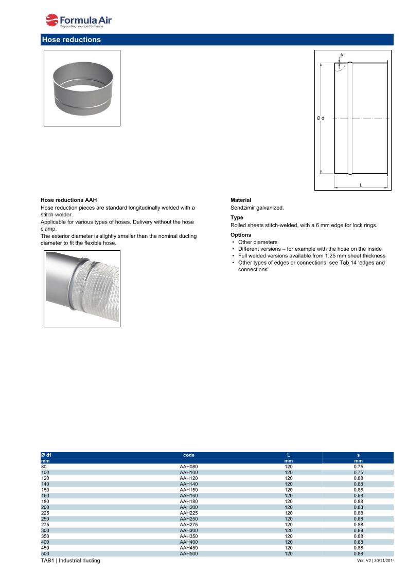
Stretched bends R=2D 60ºStretched bends are made from a welded pipe that is stretched into shape.These bends are suitable for the transport of waste materials such as dust and chips, and for the transport of grains and such, but they are especially suited for industries using oil mists because of their air-tightness.They are only produced in R=2D. If a situation requires other radiuses, please see the segmented bends in this section.
MaterialSendzimir galvanized.
TypeFully airtight stretched bends with 6 mm edges for lock rings.
Options• Other types of edges or connections, see Tab 14 ‘edges and
connections'
R=2D is in reality 2D + x mm per diameter, which is approx. R=2.3D.
Stretched bends R=2D 60º
Ø d Code R s Weightmm mm mm kg80 AB60802AAP09 184 0.88 0.29100 AB61002AAP09 224 0.88 0.50120 AB61202AAP09 264 0.88 0.65125 AB61252AAP09 267 0.88 0.72140 AB61402AAP09 304 0.88 0.94150 AB61502AAP09 319 0.88 1.08160 AB61602AAP09 344 0.88 1.22180 AB61802AAP09 384 0.88 1.51200 AB62002AAP09 424 0.88 1.87250 AB62502AAP09 520 0.88 2.95
TAB1 | Industrial ducting Ver. V2 | 10-02-15
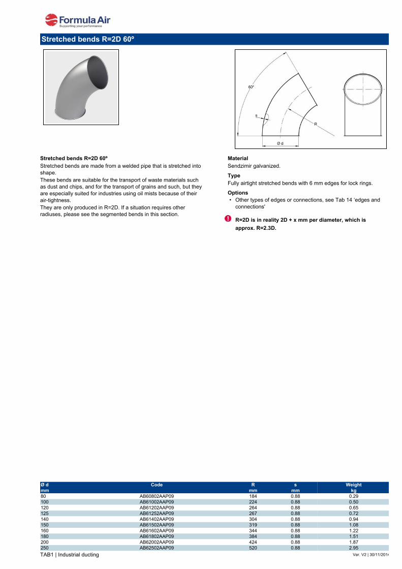
Segment bends R=1.5D 60ºBends built up from segments with a sheet thickness of 0.75 - 0.88 mm. For diameters of Ø 225 mm and larger the intermediate segments are 15°. The advantage of this is that any angle can be made
MaterialSendzimir galvanized.
TypeRolled sheet segments, stitch-welded, and lock-formed together with 6 mm edges for lock rings.
Options• Other diameters• Other sheet thickness• Full welded versions available from 1.25 mm sheet thickness• Other radiuses (R = D, R = 2D, R = 3D, R = 4D, R = 5D)• Other types of edges or connections, see Tab 14 ‘edges and
connections'
Segment bends R=1.5D 60º
Ø d Code Amount of R s Weightmm segments mm mm kg140 AB61401AAS09 2 + 2 210 0.75 0.70150 AB61501AAS09 2 + 2 225 0.75 0.77160 AB61601AAS09 2 + 2 240 0.75 0.92180 AB61801AAS09 2 + 2 270 0.75 1.13200 AB62001AAS09 2 + 2 300 0.75 1.41220 AB62201AAS09 2 + 2 330 0.75 1.69225 AB62251AAS09 2 + 2 337.5 0.75 1.76250 AB62501AAS09 2 + 2 375 0.75 2.18275 AB62751AAS09 2 + 2 412.5 0.88 2.60280 AB62801AAS09 2 + 2 420 0.88 2.70300 AB63001AAS09 2 + 2 450 0.88 3.10315 AB63151AAS09 2 + 2 472.5 0.88 3.45350 AB63501AAS09 2 + 2 525 0.88 4.22355 AB63551AAS09 2 + 2 532.5 0.88 4.35400 AB64001AAS09 2 + 2 600 0.88 5.56450 AB64501AAS09 3 + 2 675 0.88 9.00500 AB65001AAS09 3 + 2 750 0.88 11.20550 AB65501AAS09 3 + 2 825 0.88 13.50560 AB65601AAS09 3 + 2 840 0.88 14.02600 AB66001AAS09 3 + 2 900 0.88 16.10630 AB66301AAS09 3 + 2 945 0.88 16.80650 AB66501AAS09 3 + 2 975 0.88 18.80700 AB67001AAS09 3 + 2 1050 0.88 21.80710 AB67101AAS09 3 + 2 1065 0.88 22.40750 AB67501AAS09 3 + 2 1125 0.88 24.80800 AB68001AAS09 3 + 2 1200 0.88 28.10850 AB68501AAS09 3 + 2 1275 0.88 32.00900 AB69001AAS09 3 + 2 1350 0.88 36.00950 AB69501AAS09 3 + 2 1425 0.88 39.801000 AB6M101AAS09 3 + 2 1500 0.88 44.00

TAB1 | Industrial ducting Ver. V2 | 30/11/2014
Pressed bends R=1.5D 90ºThe pressed bends are made of two preformed halves and longitudinally spot-welded together.These bends are suitable for the transport of waste materials such as dust and chips but also for the transport of grains and such. They are only produced in R=1,5D. If a situation requires other radiuses, please see the segmented bends in this secti
MaterialSendzimir galvanized.
TypePressed sheets spot-welded together with 6 mm edges for lock rings.
Options• Other types of edges or connections, see Tab 14 ‘edges and
connections'
Pressed bends R=1.5D 90º
Ø d Code R s Weightmm mm mm kg80 AB9080 120 1.20 0.40100 AB9100 150 1.20 0.50120 AB9120 180 1.20 0.80125 AB9125 187.5 1.00 0.90140 AB9140 210 1.20 1.10150 AB9150 225 1.20 1.20160 AB9160 240 1.20 1.50180 AB9180 270 1.20 2.00200 AB9200 300 1.20 2.50225 AB9225 337.5 1.20 3.20250 AB9250 375 1.20 4.00275 AB9275 412.5 1.20 4.80300 AB9300 450 1.20 5.50

TAB1 | Industrial ducting Ver. V2 | 30/11/2014
Stretched bends R=2D 90ºStretched bends are made from a welded pipe that is stretched into shape.These bends are suitable for the transport of waste materials such as dust and chips, and for the transport of grains and such, but they are especially suited for industries using oil mists because of their air-tightness.They are only produced in R=2D. If a situation requires other radiuses, please see the segmented bends in this section.
MaterialSendzimir galvanized.
TypeFully airtight stretched bends with 6 mm edges for lock rings.
Options• Other types of edges or connections, see Tab 14 ‘edges and
connections'
R=2D is in reality 2D + x mm per diameter, which is approx. R=2.3D.
Stretched bends R=2D 90º
Ø d Code R s Weightmm mm mm kg80 AB90802AAP09 184 0.88 0.43100 AB91002AAP09 224 0.88 0.72120 AB91202AAP09 264 0.88 1.01125 AB91252AAP09 267 0.88 1.08140 AB91402AAP09 304 0.88 1.37150 AB91502AAP09 319 0.88 1.58160 AB91602AAP09 344 0.88 1.80180 AB91802AAP09 384 0.88 2.30200 AB92002AAP09 424 0.88 2.81250 AB92502AAP09 520 0.88 4.46

TAB1 | Industrial ducting Ver. V2 | 10-02-15
Segment bends R=1.5D 90ºBends built up from segments with a sheet thickness of 0.75 - 0.88 mm. For diameters of Ø 225 mm and larger the intermediate segments are 15°. The advantage of this is that any angle can be made
MaterialSendzimir galvanized.
TypeRolled sheet segments, stitch-welded, and lock-formed together with 6 mm edges for lock rings.
Options• Other diameters• Other sheet thickness• Full welded versions available from 1.25 mm sheet thickness• Other radiuses (R = D, R = 2D, R = 3D, R = 4D, R = 5D)• Other types of edges or connections, see Tab 14 ‘edges and
connections
Segment bends R=1.5D 90º
Ø d Code Amount of R s Weightmm segments mm mm kg140 AB91401AAS09 3 + 2 210 0.75 8.31150 AB91501AAS09 3 + 2 225 0.75 1.20160 AB91601AAS09 3 + 2 240 0.75 1.34180 AB91801AAS09 3 + 2 270 0.75 1.69200 AB92001AAS09 3 + 2 300 0.75 2.11220 AB92201AAS09 3 + 2 330 0.75 2.47225 AB92251AAS09 3 + 2 337.5 0.75 2.60250 AB92501AAS09 3 + 2 375 0.75 3.24275 AB92751AAS09 3 + 2 412.5 0.88 3.94280 AB92801AAS09 3 + 2 420 0.88 4.09300 AB93001AAS09 3 + 2 450 0.88 4.72315 AB93151AAS09 3 + 2 472.5 0.88 5.14350 AB93501AAS09 3 + 2 525 0.88 6.41355 AB93551AAS09 3 + 2 532.5 0.88 6.60400 AB94001AAS09 3 + 2 600 0.88 8.31450 AB94501AAS09 5 + 2 675 0.88 12.00500 AB95001AAS09 5 + 2 750 0.88 15.00550 AB95501AAS09 5 + 2 825 0.88 18.00560 AB95601AAS09 5 + 2 840 0.88 18.70600 AB96001AAS09 5 + 2 900 0.88 21.50630 AB96301AAS09 5 + 2 945 0.88 22.40650 AB96501AAS09 5 + 2 975 0.88 25.00700 AB97001AAS09 5 + 2 1050 0.88 29.00710 AB97101AAS09 5 + 2 1065 0.88 29.80750 AB97501AAS09 5 + 2 1125 0.88 33.00800 AB98001AAS09 5 + 2 1200 0.88 37.50850 AB98501AAS09 5 + 2 1275 0.88 42.50900 AB99001AAS09 5 + 2 1350 0.88 48.00950 AB99501AAS09 5 + 2 1425 0.88 53.001000 AB9M101AAS09 5 + 2 1500 0.88 59.00

TAB1 | Industrial ducting Ver. V2 | 06-03-17
Balance dampers ADBMOManually operated dampers by chain or rope for mounting in higher places.A sealing strip is applied on the mobile blade to insure air-tightness when open.Chain or rope not included.
MaterialSendzimir galvanized.
TypeRolled sheets stitch-welded, with 6 mm edges for lock rings.
Options• Other diameters• Other sheet thickness• Other types of edges or connections, see Tab 14 ‘edges and
connections'
Balance dampers
Ø code L1 L2 s1 s2mm mm mm mm mm80 ADBMO080 180 205 1.00 2.00100 ADBMO100 180 210 1.00 2.00140 ADBMO140 180 290 1.00 2.00150 ADBMO150 180 330 1.00 2.00160 ADBMO160 180 375 1.00 2.00180 ADBMO180 180 400 1.00 2.00200 ADBMO200 180 415 1.00 2.00225 ADBMO225 180 468 1.00 2.00250 ADBMO250 180 520 1.00 2.00275 ADBMO275 180 570 1.00 2.00300 ADBMO300 180 580 1.00 2.00315 ADBMO315 180 650 1.00 2.00350 ADBMO350 180 725 1.00 2.00400 ADBMO400 180 830 1.00 2.00450 ADBMO450 180 870 1.00 2.00500 ADBMO500 180 1005 1.00 2.00

TAB1 | Industrial ducting Ver. V2 | 30/11/2014
Sliding dampers with sealing, prepared for pneumatics ADRDRobust sliding dampers with a gasket and prepared for pneumatic cylinders. Sheet thickness of the housing/valve depends on the diameter.Up to Ø 200 mm with two gaskets (EPDM and plastic) but with only one plastic gasket from Ø 225 mm.
MaterialSt. 12.03 – electrolytically galvanized with seals.
TypeWith rubber and plastic seals up to Ø 200 mm.• Cut sheets, bolt assembly, with 6 mm edges for lock rings.
Options• Other diameters• Teflon gaskets• Stainless steel (AISI 304)• Other types of edges or connections, see Tab 14 ‘edges and
connections'
Sliding dampers with sealing, prepared for pneumatics
Ø code L1 L2 L3 L4 H s1 s2mm mm mm mm mm mm mm mm80 ADRD080 160 194 143 337 124 1.50 2.00100 ADRD100 180 226 173 399 124 1.50 2.00120 ADRD120 200 261 208 469 124 1.50 2.00125 ADRD125 200 97 217 481 125 1.50 2.00140 ADRD140 220 286 233 519 124 1.50 2.00150 ADRD150 230 301 248 549 124 1.50 2.00160 ADRD160 241 316 263 579 124 1.50 2.00180 ADRD180 261 366 313 679 124 1.50 2.00200 ADRD200 280 376 323 699 124 1.50 2.00225 ADRD225 306 438 385 823 166 2.00 3.00250 ADRD250 329 450 398 848 166 2.00 3.00275 ADRD275 404 531 481 1012 166 2.00 3.00300 ADRD300 429 543 494 1037 166 2.00 3.00315 ADRD315 444 551 501 1052 166 2.00 3.00350 ADRD350 479 608 559 1167 166 2.00 3.00375 ADRD375 504 666 616 1282 166 2.00 3.00400 ADRD400 529 678 633 1311 166 2.00 3.00450 ADRD450 582 789 678 1467 224 3.00 4.00500 ADRD500 632 829 778 1607 224 3.00 4.00550 ADRD550 734 936 878 1814 224 3.00 4.00560 ADRD560 746 944 883 1827 224 3.00 4.00600 ADRD600 789 1009 948 1957 224 3.00 4.00650 ADRD650 836 1069 1008 2077 224 3.00 4.00700 ADRD700 886 1174 1113 2287 224 3.00 4.00710 ADRD710 896 1197 1100 2297 224 3.00 4.00

TAB1 | Industrial ducting Ver. V2 | 16-02-15
Sliding dampers with sealing, pneumatically controlled ADPDRobust sliding dampers with a gasket and pneumatic cylinders. Sheet thickness of the housing/valve depends on the diameter.Up to Ø 200 mm with two gaskets (EPDM and plastic) but with only one plastic gasket from Ø 225 mm.This sliding damper is often used in combination with a machine, where the valve opens or closes when turning the machine on or off. The valve can also be used as shut-off valve beneath a silo, filter installation, etc.
MaterialSt. 12.03 – electrolytically galvanized with seals.
Type• Ø 80 up to Ø 160 mm: 1 cylinder• Ø 180 up to Ø 710 mm: 2 cylinders• Cut sheets, bolt assembly, with 6 mm edges for lock rings.• With rubber and plastic seals up to Ø 200 mm• With plastic seals as of Ø 225 mm.
Options• Protection house• Other diameters• Teflon gaskets• Stainless steel (AISI 304)• Position detectors• Other types of edges or connections, see Tab 14 ‘edges and
connections'
Please state the voltage when ordering: 24 V AC, 24 V DC, 220 V AC.
Connection of two linear pneumatic cylinders for pneumatic sliding dampers diameter Ø 180 up to Ø 630 mm.
Connection of a linear pneumatic cylinder for pneumatic dampers diameter Ø 80 up to Ø 160 mm.
Sliding dampers with sealing, pneumatically controlled
Ø code L1 L2 L3 L4 H s1 s2mm mm mm mm mm mm mm mm80 ADPD080 162 223 143 366 124 1.50 2.00100 ADPD100 182 255 173 428 124 1.50 2.00120 ADPD120 202 290 208 498 124 1.50 2.00125 ADPD125 200 297 217 481 125 1.50 2.00140 ADPD140 222 315 233 548 124 1.50 2.00150 ADPD150 232 330 248 578 124 1.50 2.00160 ADPD160 243 345 263 608 124 1.50 2.00180 ADPD180 263 395 313 708 124 1.50 2.00200 ADPD200 282 405 323 728 124 1.50 2.00225 ADPD225 308 467 385 852 124 2.00 3.00250 ADPD250 331 479 398 877 166 2.00 3.00275 ADPD275 406 560 481 1041 166 2.00 3.00300 ADPD300 431 572 494 1066 166 2.00 3.00315 ADPD315 446 580 501 1081 166 2.00 3.00350 ADPD350 481 637 559 1196 166 2.00 3.00375 ADPD375 506 695 616 1311 166 2.00 3.00400 ADPD400 531 707 633 1340 166 2.00 3.00450 ADPD450 584 818 678 1496 166 3.00 4.00500 ADPD500 634 858 778 1636 224 3.00 4.00560 ADPD560 749 973 883 1856 224 3.00 4.00600 ADPD600 792 1038 948 1986 224 3.00 4.00630 ADPD630 839 1098 1008 2106 224 3.00 4.00710 ADPD710 899 1226 1100 2326 224 3.00 4.00
TAB1 | Industrial ducting Ver. V2 | 30/11/2014
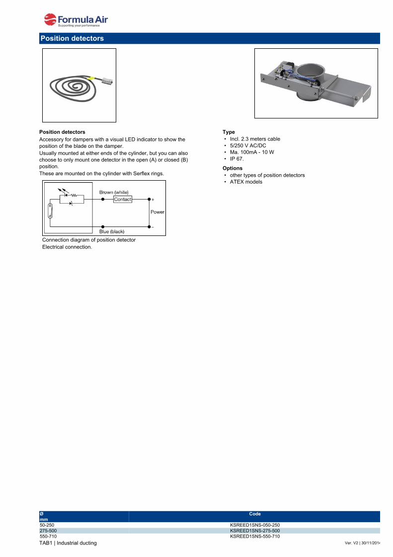
Position detectorsAccessory for dampers with a visual LED indicator to show the position of the blade on the damper.Usually mounted at either ends of the cylinder, but you can also choose to only mount one detector in the open (A) or closed (B) position.These are mounted on the cylinder with Serflex rings.
Type• Incl. 2.3 meters cable• 5/250 V AC/DC• Ma. 100mA - 10 W• IP 67.
Options• other types of position detectors• ATEX models
Connection diagram of position detectorElectrical connection.
Position detectors
Ø Codemm50-250 KSREED1SNS-050-250275-500 KSREED1SNS-275-500550-710 KSREED1SNS-550-710

TAB1 | Industrial ducting Ver. V2 | 11-12-14
Compact sliding dampers ADSCOModel from Ø80 up to Ø250.Manual, without seal. It is widely used where very little space is available. Provided with star knob to lock the blade in place.Available from Ø80 up to Ø250 included.
MaterialSendzimir galvanized.
TypePressed sheets, spot-welded together, with 6 mm edges for lock rings.
Options• None
Airflow direction (underpressure)
Compact sliding dampers
Ø code H L1 L2 L3 smm mm mm mm mm mm80 ADSCO080 40 120 150 90 1.20100 ADSCO100 40 140 168 124 1.20120 ADSCO120 40 160 185 135 1.20140 ADSCO140 55 180 220 140 1.20150 ADSCO150 60 190 230 157 1.20160 ADSCO160 60 200 235 163 1.20180 ADSCO180 64 220 278 180 1.20200 ADSCO200 64 240 305 230 1.20225 ADSCO225 64 270 325 260 1.20250 ADSCO250 64 290 345 260 1.20

Compact sliding dampers
Ø code L1 L2 L3 L4 L5 H s1 s2mm mm mm mm mm mm mm mm mm275 ADSCO275 355 170 545 432 715 107 1.50 2.00300 ADSCO300 380 182 583 457 765 107 1.50 2.00315 ADSCO315 395 190 605 472 795 107 1.50 2.00350 ADSCO350 430 207 658 507 865 107 1.50 2.00375 ADSCO375 455 220 695 532 915 107 1.50 2.00400 ADSCO400 480 232 733 557 965 107 1.50 2.00450 ADSCO450 530 257 808 607 1065 107 1.50 2.00500 ADSCO500 604 295 947 720 1242 110 2.00 3.00550 ADSCO550 654 320 1022 770 1342 110 2.00 3.00560 ADSCO560 664 325 1037 780 1362 110 2.00 3.00600 ADSCO600 704 345 1097 820 1442 110 2.00 3.00630 ADSCO630 734 360 1142 850 1502 110 2.00 3.00650 ADSCO650 754 370 1172 870 1542 110 2.00 3.00
Airflow direction (underpressure)
Compact sliding dampers ADSCOModel from Ø275 up to Ø650.Manual, without seal. It is widely used where very little space is available.Provided with one star knob to lock the blade in place up to Ø315 and with two star knobs as of Ø325.
MaterialSendzimir galvanized.
TypeCut sheets, bolt assembly, with 6 mm edges for lock rings.
Options• At 45° position for the paper industry• Other plate thickness• Other types of edges or connections, see Tab 14 ‘edges and
connections'
45º model.
Ver. V2 | 11-12-14TAB1 | Industrial ducting

TAB1 | Industrial ducting Ver. V2 | 03-09-15
Sliding dampers with sealing, heavy-duty type ADSMDRobust sliding dampers with rubber and PEHD polyether sealing ring.With Ø 80 up to Ø 200 mm the gasket is pressed into the housing.Only applied when a ducting needs to be completely open or closed.
MaterialSt. 12.03 – electrolytically galvanized with seals.
TypeWith 6 mm edges for lock rings.
Options• Other diameters• Teflon gaskets• Stainless steel (AISI 304)• Other types of edges or connections, see Tab 14 ‘edges and
connections'
Sliding dampers with sealing, heavy-duty type
Ø code L1 L2 L3 L4 H s1 s2mm mm mm mm mm mm mm mm80 ADSMD080 157 73 92 274 125 1.50 2.00100 ADSMD100 177 82 101 313 125 1.50 2.00120 ADSMD120 201 95 114 358 125 1.50 2.00125 ADSMD125 201 95 114 358 125 1.50 2.00140 ADSMD140 226 107 126 413 125 1.50 2.00150 ADSMD150 226 107 126 413 125 1.50 2.00160 ADSMD160 236 112 131 433 125 1.50 2.00180 ADSMD180 276 132 151 513 125 1.50 2.00200 ADSMD200 276 132 151 513 125 1.50 2.00225 ADSMD225 345 135 154 543 163 2.00 3.00250 ADSMD250 370 148 166 593 163 2.00 3.00275 ADSMD275 420 183 201 713 163 2.00 3.00300 ADSMD300 420 183 201 713 163 2.00 3.00350 ADSMD350 470 208 226 813 163 2.00 3.00400 ADSMD400 520 233 251 913 163 2.00 3.00450 ADSMD450 568 257 275 1009 221 2.00 3.00500 ADSMD500 618 282 300 1109 221 2.00 3.00550 ADSMD550 750 348 366 1373 221 2.00 3.00600 ADSMD600 750 348 366 1373 221 2.00 3.00630 ADSMD630 750 348 366 1373 221 2.00 3.00

ATEX sliding dampers
TAB1 | Industrial ducting
FA.T
01.ID
GALV
A.20
14.V
2.0.
UK
ADADØA-x-xxx ADADØA-ATEX-x-xxx
ADSMOØAA09A ADSMOØAA09ATEX
ATEX sliding dampers The sliding dampers from Ø80 up to Ø800 are made of two pressed elements (thickness 1,2 or 1,5 mm) welded together and zinc plated. The diaphragm is made in pressed zinc plate (thickness 1,2 or 1,5 mm). Standard with edges.
Executions Manual execution with locking bolt Ø 80 up to Ø 300 in standard or ATEX execution (II 2GDT6/T85° CX).
Pneumatic version with one cylinder from Ø 80 up to Ø 300 in standard or ATEX execution (II 2GDT6/T85° CX). A cover house can be order as an option. The electro-valve can be delivered in 24 V AC or DC, 110 V AC or 220 V AC.
Electric version from Ø 80 up to Ø 300 in standard execution.Electric actuator available in 220 V AC or 24 V DC and protection guide closing speed 18 mm/s.
ADSEDØAA09 (NOT ATEX)
Material
galvanized or stainless steel.
Options• Cover house
("C" in the code where the "x" is)
Please state the voltage when ordering: 24 V AC or DC, 110 V AC or 220 V AC.(at the end of the code: 24AC, 24DC, 110 or 220 instead of the "xxx")
Cover house
Connections Important: to avoid damages to the shutter THE STROKE SPEED OF THE CYLINDER MUST BE MODERATE (adjust with the flow regulators)
1) Solenoid valve
2) Electric switch
3) Air line
4) Cylinder
5) Flow regulators
Standard construction
Certification
II 2GDT6/T85° CX.
• ATEX version ("-ATEX" in the code)• with flanges

ATEX pneumatic sliding dampers dimensions
TAB1 | Industrial ducting
FA.T05.FE.2014.V2.0.UK
ATEX sliding dampers
Ø mm A B B1 C D H H1
80 120 150 240 280 420 40 60
100 145 190 300 330 490 50 60
120 165 210 340 370 550 50 65
125 165 210 350 370 550 50 65
140 180 220 375 405 605 50 65
150 190 237 405 415 615 50 65
160 205 245 415 445 660 50 65
180 220 280 490 530 750 50 65
200 240 310 545 545 795 50 65
220 260 330 560 595 880 65 80
225 260 330 560 595 880 75 80
240 280 340 590 630 930 55 80
250 290 362 620 650 950 65 80
260 300 370 640 675 980 75 90
280 320 390 675 705 1040 65 90
300 345 410 710 740 1095 80 90
Kg
1,1
1,3
1,5
1,5
1,7
1,8
1,9
2,3
2,5
3,8
3,9
4,7
5
5,8
6,7
7,5
ADAD080A-ATEX
ADAD100A-ATEX
ADAD120A-ATEX
ADAD125A-ATEX
ADAD140A-ATEX
ADAD150A-ATEX
ADAD160A-ATEX
ADAD180A-ATEX
ADAD200A-ATEX
ADAD220A-ATEX
ADAD225A-ATEX
ADAD240A-ATEX
ADAD250A-ATEX
ADAD260A-ATEX
ADAD280A-ATEX
ADAD300A-ATEX
Reference (ATEX versions)

ATEX sliding dampers
TAB1 | Industrial ducting
FA.T
01.ID
GAL
VA.2
014.
V2.0
.UK
ATEX sliding dampersThe reinforced sliding dampers are made of two plates fixed together by M6 bolts with two brass inner plates to permit the movement of blade without seizing. The front and back ends are closed by felt and rubber washers to have airtightness and avoid material leakage. The electric and pneumatic model over Ø 300 are equipped with protection guide (thickness 2 mm) of diaphragm and mechanism to have a correct movement in every position. Standard with edges.
Executions Manual execution with locking bolt Ø 80 up to Ø 800 in standard or ATEX execution (II 2GDT6/T85° CX).
Pneumatic version with one cylinder Ø 80 up to Ø 800 with cover house in standard or ATEX execution (II 2GDT6/T85° CX). The electro-valve can be delivered in 24 V AC or DC, 110 V AC or 220 V AC.
Electric version Ø 80 to Ø 500 in standard execution with cover house. Closing speed 18 mm/s..Available with 220 V AC or 24 V DC actuator.
Material
galvanized or stainless steel.
Connections Important: to avoid damages to the shutter THE STROKE SPEED OF THE CYLINDER MUST BE MODERATE (adjust with the flow regulators)
1) Solenoid valve
2) Electric switch
3) Air line
4) Cylinder
5) Flow regulators
Reinforced construction
Ø 80÷280 mm
Ø 300÷800 mm
Certification
II 2GDT6/T85° CX.
ADADØA-R-xxx ADADØA-ATEX-R-xxx
ADSMOØAA09-R ADSMOØAA09ATEX-R
ADSEDØAA09-R (NOT ATEX)
Options
Please state the voltage when ordering: 24 V AC or DC, 110 V AC or 220 V AC.(at the end of the code: 24AC, 24DC, 110 or 220 instead of the "xxx")
• ATEX version ("-ATEX" in the code)• with flanges

Reinforced ATEX sliding dampers dimensions
TAB1 | Industrial ducting
FA.T05.FE.2014.V2.0.UK
Ø mm A A1 B B1 H C Kg
80 220 - 270 370 120 550
100 220 - 270 370 120 550
150 270 - 300 450 120 650
200 320 - 450 650 120 850
250 370 - 450 700 120 1000
300 420 - 540 840 120 1200
350 470 600 790 1130 290 1160
400 520 650 790 1180 290 1256
450 570 700 890 1330 290 1406
500 620 750 890 1380 290 1456
550 670 814 990 1530 290 1606
600 720 864 990 1580 290 1656
650 770 914 1090 1730 290 1806
700 820 964 1090 1780 290 1856
750 870 1044 1190 1930 290 2006
800 920 1094 1190 1980 290 2056
6/8
6/8
10/12
14/16,6
19/22
23/27
30/38
35/46
40/54
48/63
58/73
69/84
76/90
80/95
86/101
91/107
Ø 80÷200 1 x ISO 32 3 mm 1,5 mm 1
Ø 220÷280 1 x ISO 40 3 mm 2 mm 1
Ø 300÷480 2 x ISO 32 3 mm 2 mm 2
Ø 500÷600 2 x ISO 40 3 mm 2 mm 2
Ø 620÷800 2 x ISO 50 3 mm 2 mm -
Ø mm N° of cylindersand type
(pneumatic)
Blade andbody thickness
Pipe piece(thickness)
N° of actuators 450 Nm 24 V DC or 220 V AC speed 18 mm/s
(electric)
ATEX sliding dampers
Cylinder / actuators details
Reference (ATEX versions)
ADAD080A-ATEX-R
ADAD100A-ATEX-R
ADAD150A-ATEX-R
ADAD200A-ATEX-R
ADAD250A-ATEX-R
ADAD300A-ATEX-R
ADAD350A-ATEX-R
ADAD400A-ATEX-R
ADAD450A-ATEX-R
ADAD500A-ATEX-R
ADAD550A-ATEX-R
ADAD600A-ATEX-R
ADAD650A-ATEX-R
ADAD700A-ATEX-R
ADAD750A-ATEX-R
ADAD800A-ATEX-R
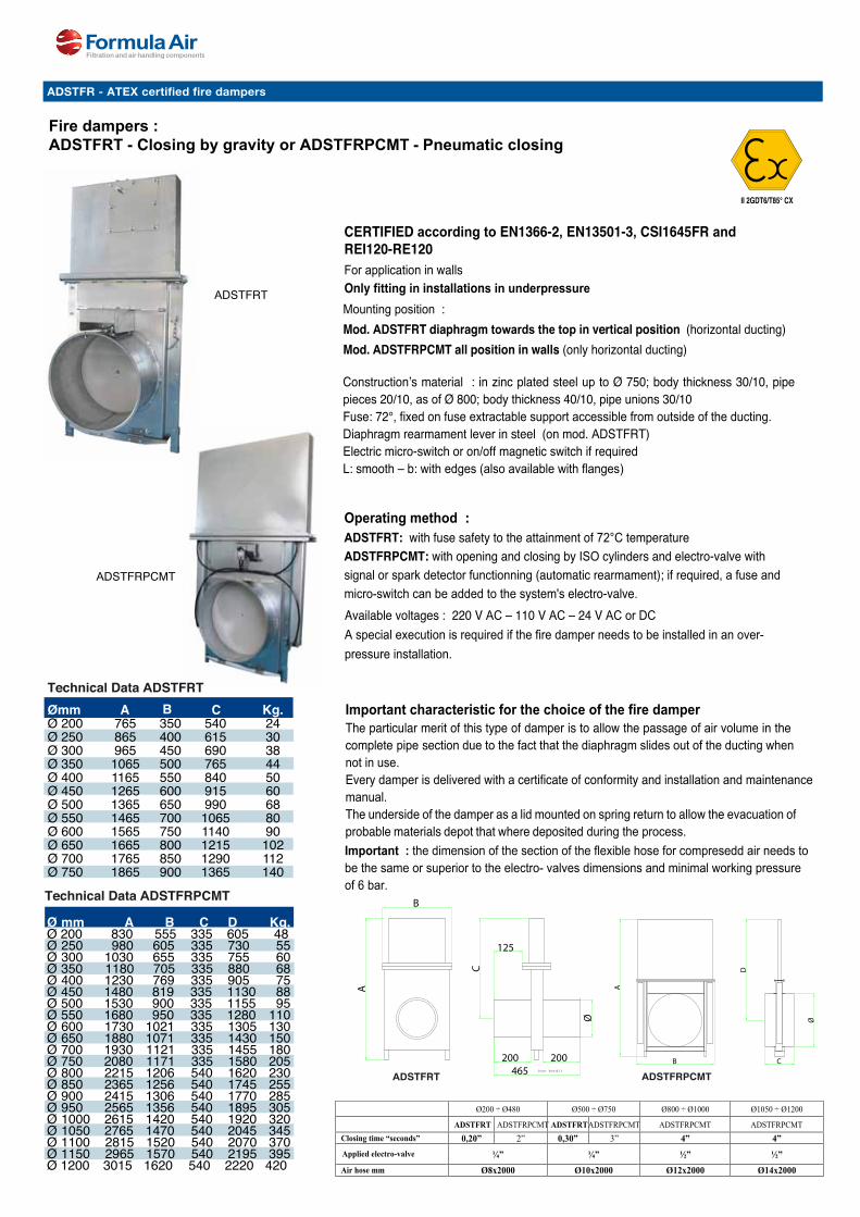
Fire dampers :ADSTFRT - Closing by gravity or ADSTFRPCMT - Pneumatic closing
CERTIFIED according to EN1366-2, EN13501-3, CSI1645FR andREI120-RE120For application in wallsOnly fitting in installations in underpressureMounting position :Mod. ADSTFRT diaphragm towards the top in vertical position (horizontal ducting) Mod. ADSTFRPCMT all position in walls (only horizontal ducting)
Construction’s material : in zinc plated steel up to Ø 750; body thickness 30/10, pipe pieces 20/10, as of Ø 800; body thickness 40/10, pipe unions 30/10Fuse: 72°, fixed on fuse extractable support accessible from outside of the ducting.Diaphragm rearmament lever in steel (on mod. ADSTFRT)Electric micro-switch or on/off magnetic switch if requiredL: smooth – b: with edges (also available with flanges)
Operating method :ADSTFRT: with fuse safety to the attainment of 72°C temperature ADSTFRPCMT: with opening and closing by ISO cylinders and electro-valve with signal or spark detector functionning (automatic rearmament); if required, a fuse and micro-switch can be added to the system's electro-valve.
Important characteristic for the choice of the fire damperThe particular merit of this type of damper is to allow the passage of air volume in the complete pipe section due to the fact that the diaphragm slides out of the ducting when not in use.Every damper is delivered with a certificate of conformity and installation and maintenance manual.The underside of the damper as a lid mounted on spring return to allow the evacuation of probable materials depot that where deposited during the process. Important : the dimension of the section of the flexible hose for compresedd air needs to be the same or superior to the electro- valves dimensions and minimal working pressure of 6 bar.
Available voltages : 220 V AC – 110 V AC – 24 V AC or DCA special execution is required if the fire damper needs to be installed in an over-pressure installation.
Important technical data for STFRPMCT
Important : the dimension of pipe line’s section of feeling air has to be same or superior to the
electro- valves dimensions and pressure work minimum 6 bar.
Available voltages 220V – 110V – 24Vac- 24Vdc
For pneumatic firebreak sash shutter for pressure installation special execution if required
Ø200 ÷ Ø480 Ø500 ÷ Ø750 Ø800 ÷ Ø1000 Ø1050 ÷ Ø1200
ADSTFRT ADSTFRPCMT ADSTFRT ADSTFRPCMT ADSTFRPCMT ADSTFRPCMT
Closing time “seconds” 0,20” 2” 0,30” 3” 4” 4”
Applied electro-valve ¼” ¼” ½” ½”
Air hose mm Ø8x2000 Ø10x2000 Ø12x2000 Ø14x2000
A
B C
D
Ø
C
A
B
125
465
Ø
(con bordi)
200 200
ADSTFRT
ADSTFRPCMT
II 2GDT6/T85° CX
Technical Data ADSTFRT Ømm A B C Kg. Ø 200 765 350 540 24Ø 250 865 400 615 30Ø 300 965 450 690 38Ø 350 1065 500 765 44Ø 400 1165 550 840 50Ø 450 1265 600 915 60Ø 500 1365 650 990 68Ø 550 1465 700 1065 80Ø 600 1565 750 1140 90Ø 650 1665 800 1215 102Ø 700 1765 850 1290 112Ø 750 1865 900 1365 140
Technical Data ADSTFRPCMT
Ø mm A B C D Kg. Ø 200 830 555 335 605 48 Ø 250 980 605 335 730 55 Ø 300 1030 655 335 755 60 Ø 350 1180 705 335 880 68 Ø 400 1230 769 335 905 75 Ø 450 1480 819 335 1130 88 Ø 500 1530 900 335 1155 95 Ø 550 1680 950 335 1280 110 Ø 600 1730 1021 335 1305 130 Ø 650 1880 1071 335 1430 150 Ø 700 1930 1121 335 1455 180 Ø 750 2080 1171 335 1580 205 Ø 800 2215 1206 540 1620 230 Ø 850 2365 1256 540 1745 255 Ø 900 2415 1306 540 1770 285 Ø 950 2565 1356 540 1895 305 Ø 1000 2615 1420 540 1920 320 Ø 1050 2765 1470 540 2045 345 Ø 1100 2815 1520 540 2070 370 Ø 1150 2965 1570 540 2195 395 Ø 1200 3015 1620 540 2220 420
ADSTFRT ADSTFRPCMT
ADSTFR - ATEX certified fire dampers

15
B
| Industrial ducting | Galvanized
FA.T
01.ID
GA
LVA
.20
20.N
SV
4.0.
EN
s1
d
H
s2
L
MaterialSendzimir galvanized
TypeRolled sheets, stitch-welded, with 6 mm edges for lock rings. Provided with regulating handle with star-knob.
Options- Other diameters- Other sheet thickness- Other types of edges or connections, see Tab 14 ‘edges and connections’
AADJ manual throttle valvesLongitudinally stitch-welded throttle valves with a material thickness of 1 mm with an inner plate with a material thickness of 3 mm.
The throttle valves have a regulating handle with star-knob to secure the valve in a fixed position. Axle seals are used along the axle ends for better airtightness.
Ø Code L H S1 S2 Weight
mm mm mm mm kg
80 AADJ000001 162 125 0.88 3.00 0.81100 AADJ000002 182 125 0.88 3.00 0.93120 AADJ000003 202 135 0.88 3.00 1.10125 AADJ000040 207 135 0.88 3.00 1.14140 AADJ000004 222 170 0.88 3.00 1.37150 AADJ000005 232 170 0.88 3.00 1.46160 AADJ000006 242 170 0.88 3.00 1.56180 AADJ000007 262 210 0.88 3.00 1.92200 AADJ000008 282 210 0.88 3.00 2.16225 AADJ000009 307 240 0.88 3.00 2.63250 AADJ000010 332 265 0.88 3.00 3.12275 AADJ000011 357 290 0.88 3.00 3.67280 AADJ000041 362 295 0.88 3.00 3.76300 AADJ000012 382 315 0.88 3.00 4.27315 AADJ000013 397 330 0.88 3.00 4.65350 AADJ000014 432 365 0.88 3.00 5.62400 AADJ000015 482 415 0.88 3.00 7.18450 AADJ000016 532 415 0.88 3.00 8.44500 AADJ000017 582 415 0.88 3.00 9.80550 AADJ000018 632 415 0.88 3.00 11.25600 AADJ000019 682 415 0.88 3.00 12.80630 AADJ000020 712 415 0.88 3.00 13.77650 AADJ000021 732 415 0.88 3.00 14.44700 AADJ000042 782 415 0.88 3.00 16.18750 AADJ000043 832 415 0.88 3.00 18.00800 AADJ000044 882 415 0.88 3.00 19.93
AADJ manual throttle valves

16
A
| Industrial ducting | Galvanized
FA.T
01.ID
GA
LVA
.20
20.N
SV
4.0.
EN
s1
d
H
s2
L
MaterialSendzimir galvanized and EPDM blade seal.
TypeRolled sheets, stitch-welded, with 6 mm edges for lock rings. Provided with regulating handle with star-knob.
Options- Other diameters- Other sheet thickness- Other valve seals, for example silicone, NBR, etc.- Other types of edges or connections, see Tab 14 ‘edges and connections’
AADJ manual throttle valves with sealLongitudinally stitch-welded throttle valves with a material thickness of 1 mm with an inner plate with a material thickness of 3 mm.
The throttle valves have a regulating handle with star-knob to secure the valve in a fixed position. Axle seals are used and a natural rubber seal is applied to the valve blade for better airtightness.
Ø Code L H S1 S2 Weight
mm mm mm mm kg
80 AADJ000025 162 125 0.88 2 x 1.00 + seal 0,78100 AADJ000026 182 125 0.88 2 x 1.00 + seal 0,88120 AADJ000027 202 135 0.88 2 x 1.00 + seal 1,03125 AADJ000046 207 135 0.88 2 x 1.00 + seal 1,06140 AADJ000028 222 170 0.88 2 x 1.00 + seal 1,26150 AADJ000029 232 170 0.88 2 x 1.00 + seal 1,34160 AADJ000030 242 170 0.88 2 x 1.00 + seal 1,42180 AADJ000031 262 210 0.88 2 x 1.00 + seal 1,74200 AADJ000032 282 210 0.88 2 x 1.00 + seal 1,94225 AADJ000033 307 240 0.88 2 x 1.00 + seal 2,34250 AADJ000034 332 265 0.88 2 x 1.00 + seal 2,77275 AADJ000035 357 290 0.88 2 x 1.00 + seal 3,24280 AADJ000045 362 295 0.88 2 x 1.00 + seal 3,30300 AADJ000036 382 315 0.88 2 x 1.00 + seal 3,75315 AADJ000037 397 330 0.88 2 x 1.00 + seal 4,08350 AADJ000038 432 365 0.88 2 x 1.00 + seal 4,90400 AADJ000039 482 415 0.88 2 x 1.00 + seal 6,23
AADJ manual throttle valves with seal

17
B
| Industrial ducting | Galvanized
FA.T
01.ID
GA
LVA
.20
20.N
SV
4.0.
EN
s2
s1 d
H
L
MaterialSendzimir galvanized and EPDM blade seal.
TypeRolled sheets, stitch-welded, with 6 mm edges for lock rings. Provided with pneumatic cylinder and solenoid valve.
Options- Execution without seal- Other diameters- Other sheet thickness- Other valve seals, for example silicone, NBR, etc.- Other types of actuator (ATEX)- Position indicator- Other types of edges or connections, see Tab 14 ‘edges and connections’
AADK Pneumatic throttle valves with sealLongitudinally stitch-welded throttle valves with a material thickness of 1 mm with an inner plate with a material thickness of 3 mm.
The valves are provided with a pneumatic rotating cylinder which opens or closes the valve. Axle seals are used and a natural rubber seal is applied to the valve blade for better airtightness.
Ø Code L H S1 S2 Weight
220V AC 24V AC 24V DC mm mm mm mm kg
80 AADK000103 AADK000073 AADK000088 250 125 0.88 2 x 1.00 + seal 2,35100 AADK000104 AADK000074 AADK000089 270 125 0.88 2 x 1.00 + seal 2,45120 AADK000105 AADK000075 AADK000090 290 135 0.88 2 x 1.00 + seal 2,60125 AADK000137 AADK000121 AADK000135 295 135 0.88 2 x 1.00 + seal 2,62140 AADK000106 AADK000076 AADK000091 310 170 0.88 2 x 1.00 + seal 2,83150 AADK000107 AADK000077 AADK000092 320 170 0.88 2 x 1.00 + seal 2,91160 AADK000108 AADK000078 AADK000093 330 170 0.88 2 x 1.00 + seal 2,99180 AADK000109 AADK000079 AADK000094 350 210 0.88 2 x 1.00 + seal 3,31200 AADK000110 AADK000080 AADK000095 370 210 0.88 2 x 1.00 + seal 3,51225 AADK000111 AADK000081 AADK000096 395 240 0.88 2 x 1.00 + seal 3,91250 AADK000112 AADK000082 AADK000097 420 265 0.88 2 x 1.00 + seal 4,34275 AADK000113 AADK000083 AADK000098 445 290 0.88 2 x 1.00 + seal 4,81280 AADK000138 AADK000127 AADK000136 450 295 0.88 2 x 1.00 + seal 4,85300 AADK000114 AADK000084 AADK000099 470 315 0.88 2 x 1.00 + seal 5,32315 AADK000115 AADK000085 AADK000100 485 330 0.88 2 x 1.00 + seal 5,65350 AADK000116 AADK000086 AADK000101 520 365 0.88 2 x 1.00 + seal 6,47400 AADK000117 AADK000087 AADK000102 570 415 0.88 2 x 1.00 + seal 7,80
AADK Pneumatic throttle valves with seal
Visual indicator mounted on axle to indicate thottle valve position
Optional position detector
Please state the voltage when ordering: 24 V AC, 24 V DC, 220 V AC.
Wiring diagram of NAMUR solenoid valve
Max. air pressure in solenoid valve : 8 BarUse only oil free dry air

18
A
| Industrial ducting | Galvanized
FA.T
01.ID
GA
LVA
.20
20.N
SV
4.0.
EN
Connection measurements to axle Connection measurements to NAMUR solenoid valve
Wiring diagram of NAMUR solenoid valve
Model A B C D E F G H I J K L M N Air Weight
mm mm mm mm mm mm mm mm mm mm mm mm mm mm Ø kg
AP2 163.5 72 65 98 26 42 24 80 30 F05 F03 M6x9 M5x8 11 G1/4” 1.70AP3 181 87.6 71 113 33 47 18 80 30 F07 F05 M8x10 M6x9 14 G1/4” 2.40
MaterialAluminum alloy body and die-cast aluminum pistons and end capsSteel alloy nickel plated drive shaftPolyamide visual rotation indicator
Type- Connection types : ISO 5211, DIN 3337, VD/VDE 3845 & NAMUR- Adjustments : +/- 5º open or close- Compressed air connections : G1/4”- Max. air pressure : 8 Bar- Torque : 8 to 58 Nm depending on air pressure- Air consumption (open/close) : AP2 - 0.09/0.12 L AP3 - 0.14/0.20 L- Working temperature : -5ºC up to +80ºC- Lubricant : none required
PCK Pneumatic actuator for AADK pneumatic throttle valvesDouble acting pneumatic actuator controlled by NAMUR valve mounted directly on the actuator which sends compressed air to the unit.
The AP2 (PCK000002) model is mounted on throttle valves up to size Ø400, and the AP3 (PCK000003) is mounted on throttle valves sizes Ø450 up to Ø800.
A visual rotation indicator is mounted on the top of the unit, but it can be replaced with an electric rotation indicator/detector (ADTPR-P) Options- Other sizes- Low or high temperature executions (-40ºC up to +150ºC)- Multi-travel rotation (120º, 135º, 180º) and three position actuators- ATEX models
PCK Pneumatic actuator for AADK pneumatic throttle valves
Max. air pressure in pneumatic cylinder : 8 Bar Use only oil free dry air

19
B
| Industrial ducting | Galvanized
FA.T
01.ID
GA
LVA
.20
20.N
SV
4.0.
EN
MaterialPolyamide exterior box (PA6) with flat polycarbonate cover (PC)Adjustable polyamide mounting bracket (PA6) reinforced with 30% fiber glassSealings EPDM and NBR, Screws AISI 304Shaft polyamide PA6
Type- Voltage : 24 - 250 V- Max. current : 250V AC - 10A, 24V DC - 0.1A- Working temperature : -25ºC up to +80ºC- Enclosure : IP67 according to DIN EN 60529- SIL level : SIL1-3 (IEC 61508:2010)- Approvals : UL available on request- Hole spacings : 80x30mm and 130x30mm - Shaft heights : 20 & 30mm (no F05 interface as standard in the bottom)- Cable gland M20 x 1,5 black (for cable Ø 6-12mm)
PCG Position detector for AADK pneumatic throttle valvesCompact and flexible limit switch box made of polyamide for simple assembly on pneumatic actuator of the throttle valves or diverters VDI/VDE 3845 in non-ATEX environment.
Simply remove the existing visual position indicator of the actuator and mount this unit in its place. Options- 3D or 3D1 indicator- F05 interface in the bottom- Other colours of casing- ATEX models
PCG Position detector for AADK pneumatic throttle valves
Wiring diagram of position detector IP67 casing with cable gland Visual position indicator on top of unit
Model Code Weight
kg
ADTPR-P PCG000095 0.48

20
A
| Industrial ducting | Galvanized
FA.T
01.ID
GA
LVA
.20
20.N
SV
4.0.
EN
s2
s1 d
H
L
MaterialSendzimir galvanized and EPDM blade seal.
TypeRolled sheets, stitch-welded, with 6 mm edges for lock rings. Provided with electric actuator and integrated visual indicator.
Options- Other diameters- Other sheet thickness- Other valve seals, for example silicone, NBR, etc.- Other types of electric motor (ATEX)- Position indicator S2-A- Other types of edges or connections, see Tab 14 ‘edges and connections’
ADTER Electric throttle valves with sealLongitudinally stitch-welded throttle valves with a material thickness of 1 mm with an inner plate with a material thickness of 3 mm.
The valves are provided with an electric rotating actuator which opens or closes the valve. Axle seals are used and a natural rubber seal is applied to the valve blade for better airtightness.
Ø Code L H S1 S2 Open/close Weight
220V AC 24V AC/DC mm mm mm mm sec. kg
80 AADL000064 AADL000049 201 125 0.88 2 x 1.00 + seal 35 1,45100 AADL000065 AADL000050 221 125 0.88 2 x 1.00 + seal 35 1,55120 AADL000066 AADL000051 241 135 0.88 2 x 1.00 + seal 35 1,70125 AADL000089 AADL000081 246 135 0.88 2 x 1.00 + seal 35 1,73140 AADL000067 AADL000052 261 170 0.88 2 x 1.00 + seal 35 1,93150 AADL000068 AADL000053 271 170 0.88 2 x 1.00 + seal 35 2,01160 AADL000069 AADL000054 281 170 0.88 2 x 1.00 + seal 35 2,09180 AADL000070 AADL000055 304 210 0.88 2 x 1.00 + seal 150 2,61200 AADL000071 AADL000056 324 210 0.88 2 x 1.00 + seal 150 2,81225 AADL000072 AADL000057 349 240 0.88 2 x 1.00 + seal 150 3,21250 AADL000073 AADL000058 374 265 0.88 2 x 1.00 + seal 150 3,64275 AADL000074 AADL000059 399 290 0.88 2 x 1.00 + seal 150 4,11280 AADL000091 AADL000085 404 295 0.88 2 x 1.00 + seal 150 4,17300 AADL000075 AADL000060 424 315 0.88 2 x 1.00 + seal 150 4,62315 AADL000076 AADL000061 439 330 0.88 2 x 1.00 + seal 150 4,95350 AADL000077 AADL000062 474 365 0.88 2 x 1.00 + seal 150 5,77400 AADL000078 AADL000063 524 415 0.88 2 x 1.00 + seal 150 7,10
AADL Electric throttle valves with seal
Visual indicator mounted on axle to indicate thottle valve position
Optional S2-A position detector
Please state the voltage when ordering: 24 V AC, 24 V DC, 220 V AC.
Wiring diagram of electric actuator

21
B
| Industrial ducting | Galvanized
FA.T
01.ID
GA
LVA
.20
20.N
SV
4.0.
EN
MaterialPrewired plastic body on metal base with metal mechanism
TypeNominal voltage : 24V AC/DC or 220V AC - 50/60 HzPower consumption : 1.5 W - 3VACable type : 1m, 3 x 0.75 mm²Torque : 5 NmAngle rotation : max. 95º adjustableSpeed : 35 sec. / 90ºSound level : 45 dB(A)Protection class : NEMA 2, UL enclosure type 2EMC : 2004/108/EC DirectiveCertification : cULus according to UL 60730-21A and UL 60730-2-214 and CAN/CSA E60730-21:02, IEC/EN 60730-21 and IEC/EN 60730-2-214Protection level : IP 54Temperature range : -30ºC up to +50ºCAmbient humidity : 95% non-condensatingMaintenance : maintenance freeAxle requirements : L = ≥20, 8mm square axle
Options- S2-A position detector
PCG Electric actuator LMC for AADL electric throttle valvesActuator for operating throttle valves and such in ventilation, dust extraction and air-conditioning systems for building services and industrial installations.
Simple direct mounting on the damper spindleby form-fit. The actuator, with its hollow shaft, is placed over the 8 mm square spindle of the throttle valve and secured by two screws.
Manual override with push-button possible (the gear is disengaged for as long as the button is pressed or remains locked).
Moutned on throttle valves Ø80 up to Ø160, they have an adjustable angle of rotation with mechanical end stops. The actuator is overload-proof, requires no limit switches and automatically stops when the end stop is reached.
Model Code Weight
24V 220V kg
ADTER-A-L AADL000053 AADL000068 0.48
PCG Electric actuator LMC for AADL electric throttle valves
Wiring diagram of electric actuator (open/close)
Wiring diagram of electric actuator(3 point control)
Please state the voltage when ordering: 24 V AC/DC or 220 V AC.
Optional S2-A position detector

22
A
| Industrial ducting | Galvanized
FA.T
01.ID
GA
LVA
.20
20.N
SV
4.0.
EN
MaterialPrewired plastic body on metal base with metal mechanism
TypeNominal voltage : 24V AC/DC or 220V AC - 50/60 HzPower consumption : 2W / 4VA or 2.5W / 6VACable type : 1m, 3 x 0.75 mm²Torque : 20 NmAngle rotation : max. 95º adjustableSpeed : 150 sec. / 90ºSound level : 45 dB(A)Protection class : NEMA 2, UL enclosure type 2EMC : 2004/108/EC DirectiveCertification : cULus according to UL 60730-22A and UL 60730-2-224 and CAN/CSA E60730-22:02, IEC/EN 60730-22 and IEC/EN 60730-2-224Protection level : IP 54Temperature range : -30ºC up to +50ºCAmbient humidity : 95% non-condensatingMaintenance : maintenance freeAxle requirements : L = ≥20, 8mm square axle
Options- S2-A position detector
PCG Electric actuator SM for AADL electric throttle valvesActuator for operating throttle valves and such in ventilation, dust extraction and air-conditioning systems for building services and industrial installations.
Simple direct mounting on the damper spindleby form-fit. The actuator, with its hollow shaft, is placed over the 8 mm square spindle of the throttle valve and secured by two screws.
Manual override with push-button possible (the gear is disengaged for as long as the button is pressed or remains locked).
Moutned on throttle valves Ø180 up to Ø800, they have an adjustable angle of rotation with mechanical end stops. The actuator is overload-proof, requires no limit switches and automatically stops when the end stop is reached.
Model Code Weight
24V 220V kg
ADTER-A-S AADL000056 AADL000071 1.00
PCG Electric actuator SM for AADL electric throttle valves
Wiring diagram of electric actuator (open/close)
Wiring diagram of electric actuator(3 point control)
Please state the voltage when ordering: 24 V AC/DC or 220 V AC.
Optional S2-A position detector

23
B
| Industrial ducting | Galvanized
FA.T
01.ID
GA
LVA
.20
20.N
SV
4.0.
EN
MaterialPlastic housing, PVC coated copper cable.
TypeVoltage : 220V AC Power : 10 WRated current : 1 mA - 3 AProtection class : completelly insulatedProtection level : IP54 (NEMA2, UL Enclosure type 2)EU directive : 2006/95/EC, low voltage equipmentCertification : IEC/EN 60730-1 and IEC/EN 60730-2-14 according to UL 60730-1A and UL 30730-2-14, and CAN/CSA E60730-1:02Working temperature : -30ºC up to +50ºCAmbiante humidity : 95%, non-condesating
PCG Position detector S2-A for AADL electric throttle valvesThese electric position indicator fit over the Belimo electric actuator range mounted on the electric throttle valves and are used to signal positions or execute switching functions in any angular position. A form-fit engagement is created between a driver disc and the spindle clamp causing the position to be directly transfered to the trip cams of the indicator. The guiding grooves between the housing ad detector ensure a tight fit.
This model has two adjustable switches, an integrated cable and is maintenance free.
Options- S1-A single switch model- FNRC models- Different cable length models
Code A (mm) according to actuator model Weight
TM..A/LM..A NM...A SM...A/SMD..A LMQ...A NMQ...A SMQ...A NKQ...A kg
PCG000030 66 69 71 80 83 89 87 0.20
PCG Position detector S2-A for AADL electric throttle valves
Wiring diagram of detectorStandard voltage : 220 V AC.
Mounting overview of detector

24
A
| Industrial ducting | Galvanized
FA.T
01.ID
GA
LVA
.20
20.N
SV
4.0.
EN
MaterialSendzimir galvanized and EPDM blade seal.Electric motor type HB50
TypeRolled sheets, stitch-welded, with 6 mm edges for lock rings. Provided with electric motor, 220 VAC, 50 Nm.
Options- Other diameters- Other sheet thickness- Other valve seals, for example silicone, NBR, etc.- Other types of electric motor (ATEX)- Other types of edges or connections, see Tab 14 ‘edges and connections’
AADL Electric throttle valves with sealLongitudinally stitch-welded throttle valves with a material thickness of 1 mm with an inner plate with seal in a material thickness of 3 mm.
The valves are provided with an electric rotating motor which opens or closes the valve. The open/close time is 30 seconds. Axle seals are used and a natural rubber seal is applied to the valve blade for better airtightness.
Ø Code L H S1 S2 Open/close Weight
220V AC 24V AC 24V DC mm mm mm mm sec. kg
80 AADL000168 AADL000214 AADL000151 295 125 0.88 2 x 1.00 + seal 30 3,28100 AADL000169 AADL000215 AADL000152 315 125 0.88 2 x 1.00 + seal 30 3,38120 AADL000170 AADL000216 AADL000153 335 135 0.88 2 x 1.00 + seal 30 3,53125 AADL000171 AADL000217 AADL000154 340 135 0.88 2 x 1.00 + seal 30 3,56140 AADL000172 AADL000218 AADL000155 355 170 0.88 2 x 1.00 + seal 30 3,76150 AADL000173 AADL000219 AADL000156 365 170 0.88 2 x 1.00 + seal 30 3,84160 AADL000174 AADL000220 AADL000157 375 170 0.88 2 x 1.00 + seal 30 3,92180 AADL000175 AADL000221 AADL000158 395 210 0.88 2 x 1.00 + seal 30 4,24200 AADL000176 AADL000222 AADL000159 415 210 0.88 2 x 1.00 + seal 30 4,44225 AADL000177 AADL000223 AADL000160 440 240 0.88 2 x 1.00 + seal 30 4,84250 AADL000178 AADL000224 AADL000161 465 265 0.88 2 x 1.00 + seal 30 5,27275 AADL000179 AADL000225 AADL000162 490 290 0.88 2 x 1.00 + seal 30 5,74280 AADL000180 AADL000226 AADL000163 495 295 0.88 2 x 1.00 + seal 30 5,80300 AADL000181 AADL000227 AADL000164 515 315 0.88 2 x 1.00 + seal 30 6,25315 AADL000182 AADL000228 AADL000165 530 330 0.88 2 x 1.00 + seal 30 6,58350 AADL000183 AADL000229 AADL000166 565 365 0.88 2 x 1.00 + seal 30 7,40400 AADL000184 AADL000230 AADL000167 615 415 0.88 2 x 1.00 + seal 30 8,73
AADL Electric throttle valves with seal
Provided with hexagonal handle for manual operation
Wiring diagram of motor
Standard voltage : 220 V AC.

25
B
| Industrial ducting | Galvanized
FA.T
01.ID
GA
LVA
.20
20.N
SV
4.0.
EN
MaterialSendzimir galvanized and EPDM blade seal.Electric motor type HB50
TypeRolled sheets, stitch-welded, with 6 mm edges for lock rings. Provided with electric motor, 220 VAC, 50 Nm.
Options- Other diameters- Other sheet thickness- Other types of electric motor (ATEX)- Other types of edges or connections, see Tab 14 ‘edges and connections’
AADL Electric throttle valves without sealLongitudinally stitch-welded throttle valves with a material thickness of 1 mm with an inner plate with a material thickness of 3 mm.
The valves are provided with an electric rotating motor which opens or closes the valve. The open/close time is 30 seconds. Axle seals are used and a natural rubber seal is applied to the valve blade for better airtightness.
Ø Code L H S1 S2 Open/close Weight
220V AC 24V AC 24V DC mm mm mm mm sec. kg
80 AADL000122 AADL000185 AADL000093 295 125 0.88 3.00 30 3.31100 AADL000123 AADL000186 AADL000094 315 125 0.88 3.00 30 3.43120 AADL000124 AADL000187 AADL000095 335 135 0.88 3.00 30 3.60125 AADL000125 AADL000188 AADL000096 340 135 0.88 3.00 30 3.64140 AADL000126 AADL000189 AADL000097 355 170 0.88 3.00 30 3.87150 AADL000127 AADL000190 AADL000098 365 170 0.88 3.00 30 39.6160 AADL000128 AADL000191 AADL000099 375 170 0.88 3.00 30 4.06180 AADL000129 AADL000192 AADL000100 395 210 0.88 3.00 30 4.42200 AADL000130 AADL000193 AADL000101 415 210 0.88 3.00 30 4.62225 AADL000131 AADL000194 AADL000102 440 240 0.88 3.00 30 5.13250 AADL000132 AADL000195 AADL000103 465 265 0.88 3.00 30 5.62275 AADL000133 AADL000196 AADL000104 490 290 0.88 3.00 30 6.17280 AADL000134 AADL000197 AADL000105 495 295 0.88 3.00 30 6.26300 AADL000135 AADL000198 AADL000106 515 315 0.88 3.00 30 6.77315 AADL000136 AADL000199 AADL000107 530 330 0.88 3.00 30 7.15350 AADL000137 AADL000200 AADL000108 565 365 0.88 3.00 30 8.12400 AADL000138 AADL000201 AADL000109 615 415 0.88 3.00 30 9.68450 AADL000139 AADL000202 AADL000110 665 415 0.88 3.00 30 10.94500 AADL000140 AADL000203 AADL000111 715 415 0.88 3.00 30 12.30550 AADL000141 AADL000204 AADL000112 765 415 0.88 3.00 30 13.75600 AADL000142 AADL000205 AADL000113 815 415 0.88 3.00 30 15.30630 AADL000143 AADL000206 AADL000114 845 415 0.88 3.00 30 16.27650 AADL000144 AADL000207 AADL000115 865 415 0.88 3.00 30 16.94700 AADL000145 AADL000208 AADL000116 915 415 0.88 3.00 30 18.68750 AADL000146 AADL000209 AADL000117 965 415 0.88 3.00 30 20.50800 AADL000147 AADL000210 AADL000118 1015 415 0.88 3.00 30 22.43
AADL Electric throttle valves without seal
Standard voltage : 220 V AC.

26
A
| Industrial ducting | Galvanized
FA.T
01.ID
GA
LVA
.20
20.N
SV
4.0.
EN
MaterialCarbon steel, aluminum alloy, bronze body polyester coated, 2 limit switches.
Other infoTorque : 50 NmVoltage : 220V AC Power : 10 WRated current : 0.24 AWorking temperature : -20°C to +70°C Mounting pad : DIN-ISO 5211, M5-M6-M8 (F03, F05 & F07) Protection class : IP67 Operating angle : 90° ±5° UL, CSA and CE certification of most units
Options- Other torques : 100, 200, 400 and 600, 1000, 2000 Nm- Other voltages : 4V DC/AC, 110V AC,380V AC & 220V AC modulante- ATEX versions
PCL Electric motor H-50 for AADL electric throttle valvesThe H-50 motor is especially suitable for the operation of ball valves and throttle valves with 90°-rotation angle.
Water resistant body with overload protection and a heating device against condensation with its self-locking secondary reducing gear to have an exact positioning.
Delivered with vertical upward optical position indicator and 2 (OPEN/CLOSE) torque switches. All other installations only after request. In order to under the condition of no power manual rotary valve, all models of the H series come standard with a manual operation.
Prominently labeled and color coded – yellow for open, red for closed – the display indicates valve position through the full range of travel. Made of high impact, heat and chemical resistant clear polycarbonate.
The motor switches are pre-wired to an easily accessible terminal block.
H-50 Voltage A B C D E F G H Ød SWOpen/close
Weight
code mm mm mm mm mm mm mm mm mm sec. kg
PCL000001 220V AC 120.5 21 46 170.5 83 120 19 30 70 9-11-14 30 2.50PCL000002 24V DC 120.5 21 46 170.5 83 120 19 30 70 9-11-14 30 2.50PCL000005 24V AC 120.5 21 46 170.5 83 120 19 30 70 9-11-14 30 2.50
PCL Electric motor HB50 for AADL electric throttle valves
Provided with hexagonal handle for manual operation
Wiring diagram of motor
Standard available in 220 V AC. The screw is only to adjust the mechanical limit switch, removal is not permitted.
Motor support dimensions

27
B
| Industrial ducting | Galvanized
FA.T
01.ID
GA
LVA
.20
20.N
SV
4.0.
EN
Material2 mm Stainless steel plate and metal spring.
TypeLaser cut plate.
Options- None
CDTZ Throttle valves spring-return kitSpecial kit to transform a ready for pneumatic throttle valve to a manual spring-return model.
One size fits all from Ø80 to Ø800.
Kit composition : handle, spring, handle support, washer, 2 bolts & nuts. Rope or chain not included.
CDTZ Throttle valves spring-return kit
Model Code Weight
kg
CDTZ AADZ000001 0.50

1000*TAB1 | Industrial ducitng Ver. V2 | 15-03-2017
Compact limit switch box
Technical features
Part number
Producer switch
Switch type
Voltage
Maximum Current
Contacts
SIL Level
Temperature
Approvals
CHERRY
D44X
24-250V
AC: 250V, 10ADC: 24V, 2,5A
Silver
SIL 1-3 (IEC 61508:2010)
Polyamide: -25°C ... +80°C Aluminium: (-40°C) -25°C ... +80°C
UL available on request
CHERRY
D41X
24-250V
AC: 250V, 0,1ADC: 24V, 0,1A
Gold
SIL 1-3 (IEC 61508:2010)
Polyamide: -25°C ... +80°C Aluminium: (-40°C) -25°C ... +80°C
UL available on request
Part number EPP2M01, EPE2M01EAE2M01
EPP2M01-G, EPE2M01-GEAE2M01-G
CROUZET
83161.801
24-250V
Silver: AC: 250V, 10A / DC: 24V, 2,5A Gold: AC: 250V, 0,1A / DC: 24V, 0,1A
Silver/Gold
SIL 1-3 (IEC 61508:2010)
Polyamide: -25°C ... +80°C Aluminium: (-40°C) -25°C ... +80°C (+120°C)
GOST / UL
EPP2M01-488, EPE2M01-488EAE2M01-488
M001: 1 2 3 4 5 6 7 8 9 10 11 12
Article number
-EPAV
-Housing
Polyamide AluminumVestamide
BracketPE
Polyamide Stainless steel
Sc Switches1234
Piece Pieces Pieces Pieces
MISD
Schalterart Switch type Mechanical Inductive Slot type Dual sensor
00010203
04050607
50x25x2080x30x2080x30x30130x30x30
Hole spacing130x30x50*80x30x40*80x30x50*130x30x20
080910
130x30x40*50x25x30F05
G488
TypeCherry, D44XCherry, D41XCrouzet, 83161.801
Options
1 2 1 2
COIL COIL
Top
switch
Botto
m
switch
*These hole spacings are only available with stainless steel bracket.
optional

9Tab 1 | Industrial ducting | Galvanized
FA.T
01.ID
GA
LVA
.201
7.V
2.0.
EN
d2
d3
d1
50
L1
50
L2 L3
45°
s
Branches at 45º
Branches at 45ºBranches are made with a spot-welded branch and are longitudinally welded with a stitch-welder.
All our branches are produced so that all types of rings can be used to mount them.
The table below will indicate the total length L1 depending on the diameter ØD2 of the side branch.
ØD1 ØD2 ØD3 L1 L2 L3 Type mm mm mm mm mm mm
80 300 100 300 120 350 125 350 140 350 150 400 160 400 175 400 180 400 200 450 220 500 224 500 225 500 250 500 275 600 280 600 300 600 315 600 350 700 355 800 400 800 425 900 450 950 475 950 500 950 550 1.050 560 1.050 600 1.150 630 1.150 650 1.150 700 1.300 710 1.300 750 1.300 800 1.450 850 1.450 900 1.650 950 1.700
1.000 1.800
MaterialSendzimir galvanized.
TypeRolled stitch-welded sheets with 6 mm edges for lock rings.Branch piece spot-welded on body with Tersotat for airtightness.
Options- other diameters- other sheet thicknesses- full welded versions available from 1.25 mm sheet thickness- other types of edges or connections, see Tab 14 ‘edges and
connections’
Use
r ch
oice
s fr
om s
tand
ard
or
mod
ified
dia
met
ers
Use
r ch
oice
s fr
om s
tand
ard
or
mod
ified
dia
met
ers
To b
e ca
lcul
ated
with
the
CP
Q t
ool o
r ot
her
ded
icat
ed t
ool
To b
e ca
lcul
ated
with
the
CP
Q t
ool o
r ot
her
ded
icat
ed t
ool
FB o
r FB
E o
r FB
B d
epen
ds
on t
he u
ser
sele
ctio
n of
dia
met
ers
Ød
1 &
Ød
3 to
mak
e su
re t
hat
all t
ypes
of r
ings
fit
dur
ing
asse
mb
ly
d3
d2
d1
L3
45°
L2
L1
s

TAB1 | Industrial ducting Ver. V2 | 30/11/2014
T-branches at 90° AEB9T-branches are made with a spot-welded branch and are longitudinally welded with a stitch-welder.
MaterialSendzimir galvanized.
TypeRolled sheets, stitch-welded, branch piece spot-welded on body, with 6 mm edges for lock rings.
Options• Other diameters• Other sheet thickness• Full welded versions available from 1.25 mm sheet thickness• Other types of edges or connections, see Tab 14 ‘edges and
connections'
Size d2 < d1
T-branches at 90°
Code Ø d1/d2 L1 L2 L3 s Weightmm mm mm mm mm kg
AEB9080 80 115 75 230 0.88 on requestAEB9100 100 125 75 250 0.88 on requestAEB9120 120 135 75 270 0.88 on requestAEB9125 125 138 75 275 0.88 on requestAEB9140 140 145 75 290 0.88 on requestAEB9150 150 150 75 300 0.88 on requestAEB9160 160 155 75 310 0.88 on requestAEB9180 180 165 75 330 0.88 on requestAEB9200 200 175 75 350 0.88 on requestAEB9220 220 213 100 425 0.88 on requestAEB9225 225 213 100 425 0.88 on requestAEB9250 250 225 100 450 0.88 on requestAEB9275 275 238 100 475 0.88 on requestAEB9300 300 250 100 500 0.88 on requestAEB9315 315 258 100 515 0.88 on requestAEB9350 350 275 100 550 0.88 on requestAEB9355 355 275 100 550 0.88 on requestAEB9400 400 300 100 600 0.88 on requestAEB9450 450 375 150 750 0.88 on requestAEB9500 500 400 150 800 0.88 on requestAEB9550 550 425 150 850 0.88 on requestAEB9560 560 425 150 850 0.88 on requestAEB9600 600 450 150 900 0.88 on requestAEB9630 630 465 150 930 0.88 on requestAEB9650 650 475 150 950 0.88 on requestAEB9700 700 550 200 1100 0.88 on requestAEB9710 710 550 200 1100 0.88 on requestAEB9750 750 575 200 1150 0.88 on requestAEB9800 800 600 200 1200 0.88 on requestAEB9850 850 625 200 1250 0.88 on requestAEB9900 900 650 200 1300 0.88 on requestAEB9950 950 675 200 1350 0.88 on requestAEB9M10 1000 700 200 1400 0.88 on request

TAB1 | Industrial ducting Ver. V2 | 14-01-15
T-pieces 90° - specialT-pieces are made with a spot-welded branch and are longitudinally welded with a stitch-welder.
MaterialSendzimir galvanized.
TypeRolled sheets, stitch-welded, branch piece spot-welded on body, with 6 mm edges for lock rings.
Options• Other diameters• Other sheet thickness• Custom made versions• Full welded versions available from 1.25 mm sheet thickness• Other types of edges or connections, see Tab 14 ‘edges and
connections'
T-pieces 90° - special
Ø d1 Ø d2 L smm mm mm mm80 on request 234 0.88100 on request 254 0.88120 on request 274 0.88125 on request 279 0.88140 on request 294 0.88150 on request 304 0.88160 on request 314 0.88180 on request 334 0.88220 on request 374 0.88225 on request 379 0.88250 on request 404 0.88275 on request 429 0.88280 on request 434 0.88300 on request 454 0.88315 on request 469 0.88350 on request 504 0.88400 on request 554 0.88450 on request 604 0.88500 on request 654 0.88550 on request 704 0.88560 on request 714 0.88600 on request 754 0.88650 on request 804 0.88700 on request 854 0.88710 on request 864 0.88750 on request 904 0.88800 on request 954 1.00850 on request 1004 1.00900 on request 1054 1.00950 on request 1104 1.001000 on request 1154 1.00

TAB1 | Industrial ducting Ver. V2 | 30/11/2014
Adjustable blanking plates AOPAThe adjutable blanking paltes are attached to the end of a ducting system or on a branch to manually regulate the airflow.
MaterialSendzimir galvanized.
TypeCut sheets assembled with star knob.
Options• Other diameters
Standard application with slim rings.
Adjustable blanking plates
Ø d1 code Ø d2 L smm mm mm mm80 AOPA080 94 30 1.50100 AOPA100 114 30 1.50120 AOPA120 134 30 1.50140 AOPA140 154 30 1.50150 AOPA150 164 30 1.50180 AOPA180 194 30 1.50200 AOPA200 214 30 1.50250 AOPA250 264 30 1.50275 AOPA275 289 30 1.50

TAB1 | Industrial ducting Ver. V2 | 30/11/2014
Blanking plates AOPBlanking plates are standard made out of Sendzimir plate and are used to close a duct, for example at the end of a ducting system or on a branch that is not being used.
MaterialSendzimir galvanized.
TypeCut sheets.
Options• Other diameters• Other sheet thickness
Standard assembly with slim rings.
Blanking plates
Ø d pipe code Ø d1 smm mm mm80 AOP080 94 0.88100 AOP100 114 0.88120 AOP120 134 0.88140 AOP140 154 0.88150 AOP150 164 0.88160 AOP160 174 0.88180 AOP180 194 0.88200 AOP200 214 0.88225 AOP225 239 0.88250 AOP250 264 0.88275 AOP275 289 0.88300 AOP300 314 0.88315 AOP315 319 0.88325 AOP325 239 0.88350 AOP350 364 0.88375 AOP375 389 0.88400 AOP400 414 0.88450 AOP450 464 0.88500 AOP500 514 0.88

10
A
Tab 1 | Industrial ducting | Galvanized
FA.T
01.ID
GA
LVA
.201
7.V
2.0.
EN
ØdØD
L
50 50
FBBL
ØdØD
FBE
Tapers
TapersTapers are longitudinally welded with a stitch-welder.
All our tapers are produced so that all types of rings can be used to mount them.
When the diameter difference between ØD and Ød is small, the taper is done with out extra straight extensions (FBE model).
When the diameter difference between ØD and Ød is more than 25 mm, the taper is produced with two straight extensions to fit all rings (FBB model).
How to see which model will be produced based on the diameter differences can be seen in the table below.
MaterialSendzimir galvanized.
TypeRolled stitch-welded sheets with 6 mm edges for lock rings.
Options- other diameters- other sheet thicknesses- full welded versions available from 1.25 mm sheet thickness- other types of edges or connections, see Tab 14 ‘edges and
connections’
Δd - ( D-d (mm))
350 400 110010501000950900850800750700650600550500450
475
450
425
400
375
350
325
300
275
250
225
200
175
150
125
100
FBE
L (mm)
FBBFBBFBBFBBFBBFBBFBBFBBFBBFBBFBBFBBFBBFBBFBB
25
350250250
75
50
30
250
FBBFBBFBB
FBB = 50 mm straight piece so that all rings fit
Δd-74 mm - 50 m
m
Δd-99 mm - 75 m
m
Δd-124 mm - 100 m
m
Δd-149 mm - 125 m
m
Δd-174 mm - 150 m
m
Δd-199 mm - 175 m
m
Δd-224 mm - 200 m
m
Δd-249 mm - 225 m
m
Δd-274 mm - 250 m
m
Δd-299 mm - 275 m
m
Δd-324 mm - 300 m
m
Δd-349 mm - 325 m
m
Δd-374 mm - 350 m
m
Δd-399 mm - 375 m
m
Δd-424 mm - 400 m
m
Δd-449 mm - 425 m
m
Δd-474 mm - 450 m
m

TAB1 | Industrial ducting Ver. V2 | 14-01-15
Transition pieces AUThe transition pieces are produced from bent sheets spot-welded longitudinally. They are designed for a smooth transition between round and rectangular ducting elements.As a standard, they are produced symmetrically but eccentric (or asymmetrical) models can be produced on request.Depending on the needs of the client or situation, different versions are possible for use with all kinds of furnishings as shown in the drawings above.The length of the transition piece is based on production standards but other variations can be produced on request.
Sheet thicknessesØD < à 750 mm = 0,88 mmØD > à 800 mm = 1,00 mm
MaterialSendzimir galvanized.
TypePreformed sheets spot-welded together.
Options• Other diameters• Asymmetrical version• Other sheet thickness• Full welded versions available from 1.25 mm sheet thickness• Other types of edges or connections, see Tab 14 ‘edges and
connections'
Due to the possibilities, we cannot give accurate data on this product. Please request the technical information when placing your order.
Transition pieces
Ø d1 Code L1 L2 smm mm mm mmon request on request on request on request on request

TAB1 | Industrial ducting Ver. V2 | 30/11/2014
Sweep-ups AVBSweep-ups for the suction of dust, wood particles and debris in a workshop.Standard longitudinally welded with a stitch-welder.
MaterialSendzimir galvanized.
TypeRolled sheets stitch-welded and spot-welded, with a 6 mm edge for lock rings.
Options• Without grill and cover, type AVA• Other diameters• Other materials• Other types of edges or connections, see Tab 14 ‘edges and
connections'
Sweep-ups
Ø d code H s Weightmm mm mm kg100 AVB100 390 0.88 1.5120 AVB120 390 0.88 2.0140 AVB140 390 0.88 2.5150 AVB150 390 0.88 3.0160 AVB160 390 0.88 3.5180 AVB180 390 0.88 4.0200 AVB200 390 0.88 4.5

TAB1 | Industrial ducting Ver. V2 | 18-08-15
Central collectors (Spoutnik) AVKThe central collectors are standard made of spot-welded sheets.They are designed for centralizing dust removal from one machine or a group of machines. Usually directly connected to the machines by means of flexible hoses, but other types of connections are possible.The suction points can vary in number as well as in their finishing. These will have to be specified when ordering.
MaterialSendzimir galvanized.
TypeRolled sheets stitch-welded and spot-welded, with a 6 mm edge for lock rings.
Options• Other diameters• Other sheet thickness• With inner cone for a uniform airflow• Other types of edges or connections, see Tab 14 ‘edges and
connections'• Full welded versions available from 1.25 mm sheet thickness
Specify number of suction points and diameters when ordering. Maximun 9 points.
Example: AVC100-4-80H09: Ø100 with edge (fbb) spoutnik with 4 suction points Ø80 for flexible hoses (fsl).
Central collectors (Spoutnik) AVK
Ø d1 Code Ø d2 Ø d3 L1 L2 smm mm mm mm mm mm80 AVK080-quantity-Ø On request 160 120 60 0.88100 AVK100-quantity-Ø On request 200 150 75 0.88120 AVK120-quantity-Ø On request 240 180 90 0.88125 AVK125-quantity-Ø On request 250 190 95 0.88140 AVK140-quantity-Ø On request 280 210 105 0.88150 AVK150-quantity-Ø On request 300 230 115 0.88160 AVK160-quantity-Ø On request 320 240 120 0.88180 AVK180-quantity-Ø On request 360 270 135 0.88200 AVK200-quantity-Ø On request 400 300 150 0.88225 AVK225-quantity-Ø On request 450 340 170 0.88250 AVK250-quantity-Ø On request 500 380 190 0.88300 AVK300-quantity-Ø On request 600 450 225 0.88315 AVK315-quantity-Ø On request 630 480 240 0.88350 AVK350-quantity-Ø On request 700 530 265 0.88400 AVK400-quantity-Ø On request 800 600 300 0.88450 AVK450-quantity-Ø On request 900 680 340 0.88500 AVK500-quantity-Ø On request 1000 750 375 0.88
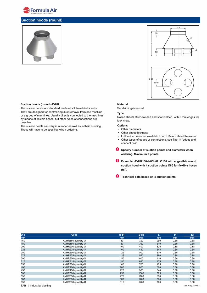
TAB1 | Industrial ducting Ver. V2 | 21-04-15
Suction hoods (round) AVHRThe suction hoods are standard made of stitch-welded sheets.They are designed for centralizing dust removal from one machine or a group of machines. Usually directly connected to the machines by means of flexible hoses, but other types of connections are possible.The suction points can vary in number as well as in their finishing. These will have to be specified when ordering.
MaterialSendzimir galvanized.
TypeRolled sheets stitch-welded and spot-welded, with 6 mm edges for lock rings.
Options• Other diameters• Other sheet thickness• Full welded versions available from 1.25 mm sheet thickness• Other types of edges or connections, see Tab 14 ‘edges and
connections'
Specify number of suction points and diameters whenordering. Maximum 9 points.
Example: AVHR100-4-80H09: Ø100 with edge (fbb) roundsuction hood with 4 suction points Ø80 for flexible hoses(fsl).
Technical data based on 4 suction points.
Suction hoods (round)
Ø d Code Ø d1 Ø d2 L s1 s2mm mm mm mm mm mm160 AVHR160-quantity-Ø 80 320 290 0.88 0.88180 AVHR180-quantity-Ø 80 360 310 0.88 0.88200 AVHR200-quantity-Ø 100 400 325 0.88 0.88225 AVHR225-quantity-Ø 100 450 345 0.88 0.88250 AVHR250-quantity-Ø 125 500 370 0.88 0.88275 AVHR275-quantity-Ø 125 550 390 0.88 0.88300 AVHR300-quantity-Ø 150 600 410 0.88 0.88315 AVHR315-quantity-Ø 150 630 425 0.88 0.88350 AVHR350-quantity-Ø 160 700 455 0.88 0.88400 AVHR400-quantity-Ø 200 800 500 0.88 0.88450 AVHR450-quantity-Ø 225 900 540 0.88 0.88500 AVHR500-quantity-Ø 250 1000 585 0.88 0.88550 AVHR550-quantity-Ø 275 1100 630 0.88 0.88600 AVHR600-quantity-Ø 300 1200 670 0.88 0.88630 AVHR630-quantity-Ø 315 1260 700 0.88 0.88

TAB1 | Industrial ducting Ver. V2 | 30/11/2014
Suction hoods (rectangular) AVHSThe suction hoods are standard made of spot-welded sheets.They are designed for centralizing dust removal from one machine or a group of machines. Usually directly connected to the machines by means of flexible hoses, but other types of connections are possible.The suction points can vary in number as well as in their finishing. These will have to be specified when ordering.
MaterialSendzimir galvanized.
TypeRolled sheets stitch-welded and spot-welded, with 6 mm edges for lock rings.
Options• Other diameters• Other sheet thickness• Full welded versions available from 1.25 mm sheet thickness• Other types of edges or connections, see Tab 14 ‘edges and
connections'
Specify number of suction points and diameters when ordering. Maximun 9 points.
Example: AVHS100-4-80H09: Ø100 with edge (fbb) rectangular suction hood with 4 suction points Ø80 for flexible hoses (fsl).
Technical data based on 4 suction points.
Suction hoods (rectangular)
Ø d Code Ø d1 L1 L2 L3 s1 s2mm mm mm mm mm mm mm160 AVHS160-quantity-Ø 80 445 100 470 0.88 0.88180 AVHS180-quantity-Ø 80 425 100 470 0.88 0.88200 AVHS200-quantity-Ø 100 480 120 550 0.88 0.88225 AVHS225-quantity-Ø 100 455 120 550 0.88 0.88250 AVHS250-quantity-Ø 125 520 145 650 0.88 0.88275 AVHS275-quantity-Ø 125 500 145 650 0.88 0.88300 AVHS300-quantity-Ø 150 565 170 750 0.88 0.88315 AVHS315-quantity-Ø 150 550 170 750 0.88 0.88350 AVHS350-quantity-Ø 160 555 180 790 0.88 0.88400 AVHS400-quantity-Ø 200 650 220 950 0.88 0.88450 AVHS450-quantity-Ø 225 695 245 1050 0.88 0.88500 AVHS500-quantity-Ø 250 740 270 1150 0.88 0.88550 AVHS550-quantity-Ø 275 780 295 1250 0.88 0.88600 AVHS600-quantity-Ø 300 825 320 1350 0.88 0.88630 AVHS630-quantity-Ø 315 850 335 1410 0.88 0.88

TAB1 | Industrial ducting Ver. V2 | 18-08-15
Suction hoods AVCThe suction hoods are produced from bent sheets spot-welded longitudinally. Often used to remove loaded air over a work station, they are also designed to be integrated in other equipment.As a standard, they are produced symmetrically but eccentric (or asymmetrically) models can be produced on request.Depending on the needs of the client or situation, different versions are possible for use with all kinds of rings.The lengths of the suction hoods are based on our production standards but other variations can be produced on request.
Sheet thicknessD < 750: 0.88 mmD < 800: 1.00 mm
MaterialSendzimir galvanized.
TypePreformed sheets spot-welded together.
Options• Other diameters• Asymmetrical version• Other sheet thickness• Full welded versions available from 1.25 mm sheet thickness• Other types of edges or connections, see Tab 14 ‘edges and
connections'
Due to the possibilities, we cannot give accurate data on this product. Please request the technical information when placing your order.
Suction hoods AVC
Ø d code L1 L2 smm mm mm mmon request on request on request on request on request

Block traps AVVThe block traps are provided to stop big parts. It is mainly used in the wood processing industry.Supplied with a lever on the access door with an adjustable counterweight.
MaterialSendzimir galvanized.
TypeRolled and cut sheets, spot-welded together, with 6 mm edges for lock rings.
Options• Other diameters• With grill• Other sheet thickness• Full welded versions available from 1.25 mm sheet thickness• Other types of edges or connections, see Tab 14 ‘edges and
connections'
Counterweight needs to be adjusted on site depending on the need of the customer.
Horizontal mounting only.
Grill (option) mounting diagram with airflow.
Block traps
600TAB1 | Industrial ducting Ver. V2 | 04-04-16
Ø d code L1 L2 s s ductmm mm mm mm mm200 AVV200 600 550 2.00 0.88250 AVV250 600 575 2.00 0.88300 AVV300 600 600 2.00 0.88350 AVV350 600 625 2.00 0.88400 AVV400 600 650 2.00 0.88450 AVV450 600 675 2.00 0.88500 AVV500 600 700 2.00 0.88550 AVV550 600 725 2.00 0.88
AVV600 600 800 2.00 0.88

TAB1 | Industrial ducting Ver. V2 | 30/11/2014
Exhaust caps round AWEExhaust caps are standard welded with a stitch-welder. Internally provided with an inner cone with a drain for rainwater.The top is provided with bird screen with upwards discharge so there will be no recoil of potential pollution on the roof.
MaterialSendzimir galvanized.
TypeRolled sheets stitch-welded and spot-welded, with a 6 mm edge for lock rings.
Options• Other diameters• Other sheet thickness• Full welded versions available from 1.25 mm sheet thickness• Other types of edges or connections, see Tab 14 ‘edges and
connections'
Exhaust caps round
Ø d1 code Ø d2 H L1 L2 s1mm mm mm mm mm mm200 AWE200 300 380 110 270 0.88225 AWE225 350 430 120 310 0.88250 AWE250 350 480 140 340 0.88275 AWE275 400 525 150 375 0.88300 AWE300 450 570 160 410 0.88315 AWE315 500 600 170 430 0.88350 AWE350 500 670 190 480 0.88400 AWE400 600 760 210 550 0.88450 AWE450 650 860 250 610 0.88500 AWE500 750 950 270 680 0.88550 AWE550 800 1050 300 750 0.88600 AWE600 850 1150 330 820 0.88630 AWE630 900 1200 340 860 0.88650 AWE650 950 1240 350 890 0.88700 AWE700 1000 1340 390 950 0.88750 AWE750 1100 1430 410 1020 0.88800 AWE800 1160 1530 440 1090 0.88850 AWE850 1240 1620 460 1160 0.88900 AWE900 1310 1720 520 1200 0.88950 AWE950 1380 1810 610 1200 0.881000 AWEM10 1450 1910 710 1200 0.88

TAB1 | Industrial ducting Ver. V2 | 05-01-15
Flash roof passages AWFThe flash roof passages are made of molded EPDM rubber with an integrated aluminum profile.Because it is very flexible it can be mounted on all kinds of roofs.The passage can be adjusted to the diameter of the pipe used and is also waterproof.A storm collar is not necessary with this product.To garantee a proper sealing, the passage should normally be 20 mm smaller than the pipe diameter.
MaterialEPDM rubber. (up to +100ºC, intermittent up to +135ºC)
Option• Silicone model. (up to +220ºC, intermittent up to +260ºC)
Flash roof passages
code Ø d1 Ø d2 Lmm mm mm
AWF4 70 177 254AWF5 101 209 279AWF6 121 254 304AWF7 140 292 355AWF8 171 343 431AWF9 241 520 635AWF12 305 724 863
code Ø d1 Ø d2 Lmm mm mm
AWF4S 70 177 254AWF5S 101 209 279AWF6S 121 254 304AWF7S 140 292 355AWF8S 171 343 431AWF9S 241 520 635AWF12S 304 724 863

TAB1 | Industrial ducting Ver. V2 | 30/11/2014
Jet caps AWJJet caps are standard spot-welded and consist of 2 cones that are seamed together, internally provided with inner cone with a drain for rainwater (rigid copper pipe).The outlet side is provided with a bird screen.Because of the vertical outlet there is less resistance and a higher outflow than with a rain cap.
MaterialSendzimir galvanized.
TypeRolled sheets stitch-welded and spot-welded, with a 6 mm edge for lock rings.
Options• Other diameters• Other sheet thickness• Full welded versions available from 1.25 mm sheet thickness• Other types of edges or connections, see Tab 14 ‘edges and
connections'
Diagram of pressure loss
Jet caps
Ø d1 code Ø d2 H smm mm mm mm100 AWJ100 165 370 0.75120 AWJ120 185 425 0.75140 AWJ140 215 465 0.75150 AWJ150 230 490 0.88160 AWJ160 245 510 0.88180 AWJ180 275 545 0.88200 AWJ200 305 590 0.88225 AWJ225 345 635 0.88250 AWJ250 380 690 0.88275 AWJ275 420 740 0.88300 AWJ300 460 790 0.88315 AWJ315 480 820 0.88350 AWJ350 535 936 0.88400 AWJ400 610 1036 0.88450 AWJ450 690 1136 0.88500 AWJ500 765 1244 0.88550 AWJ550 840 1350 0.88600 AWJ600 915 1450 0.88630 AWJ630 960 1540 0.88650 AWJ650 990 1540 0.88700 AWJ700 1070 1658 1.25750 AWJ750 1145 1746 1.25800 AWJ800 1220 1695 1.25850 AWJ850 1295 1795 1.25900 AWJ900 1375 1950 1.25950 AWJ950 1450 1975 1.251000 AWJM10 1525 2120 1.25

TAB1 | Industrial ducting Ver. V2 | 30/11/2014
Wall passages AWMThe wall passages are laser cut and divided into two parts, which have an overlap for a smooth finishing.
MaterialSendzimir galvanized.
TypeCut sheets.
Options• Other versions (round, square, ...)• Other sheet thicknesses• RAL color
Wall passages
Ø d code Ø d1 L1 L2 smm mm mm mm mm080 AWM080 80 + 2.5 280 280 0.88100 AWM100 100 + 2.5 300 300 0.88120 AWM120 120 + 2.5 320 320 0.88140 AWM140 140 + 2.5 340 340 0.88150 AWM150 150 + 2.5 350 350 0.88160 AWM160 160 + 2.5 360 360 0.88180 AWM180 180 + 2.5 380 380 0.88200 AWM200 200 + 2.5 400 400 0.88220 AWM220 220 + 2.5 420 420 0.88225 AWM225 225 + 2.5 425 425 0.88250 AWM250 250 + 2.5 450 450 0.88275 AWM275 275 + 2.5 475 475 0.88280 AWM280 280 + 2.5 480 480 0.88300 AWM300 300 + 2.5 500 500 0.88315 AWM315 315 + 2.5 515 515 0.88350 AWM350 350 + 2.5 550 550 0.88355 AWM355 355 + 2.5 555 555 0.88400 AWM400 400 + 2.5 600 600 0.88450 AWM450 450 + 2.5 650 650 0.88500 AWM500 500 + 2.5 700 700 0.88550 AWM550 550 + 2.5 750 750 0.88560 AWM560 560 + 2.5 760 760 0.88600 AWM600 600 + 2.5 800 800 0.88630 AWM630 630 + 2.5 830 830 0.88650 AWM650 650 + 2.5 850 850 0.88700 AWM700 700 + 2.5 900 900 0.88710 AWM710 710 + 2.5 910 910 0.88750 AWM750 750 + 2.5 950 950 0.88800 AWM800 800 + 2.5 1000 1000 0.88850 AWM850 850 + 2.5 1050 1050 0.88900 AWM900 900 + 2.5 1100 1100 0.88950 AWM950 950 + 2.5 1150 1150 0.881000 AWMM10 1000 + 2.5 1200 1200 0.88

TAB1 | Industrial ducting Ver. V2 | 30/11/2014
Rain caps AWRRain caps are standard spot-welded. Delivery without bird screen.The cone is attached to the body with 3 legs in 3 mm sheet thickness.Diameters up to Ø 140 with edge and Ø 150 up to Ø 1000 with edge and inner cone.
MaterialSendzimir galvanized.
TypeRolled sheets stitch-welded and spot-welded, with a 6 mm edge for lock rings.
Options• Other diameters• Customer specific execution• Other sheet thickness• With bird screen• Full welded versions available from 1.25 mm sheet thickness• Other types of edges or connections, see Tab 14 ‘edges and
connections'
Rain caps
Ø d1 code Ø d2 H A B s1 s2mm mm mm mm mm mm mm80 AWR080 200 130 50 75 0.88 0.88100 AWR100 200 130 50 75 0.88 0.88120 AWR120 250 150 50 75 0.88 0.88140 AWR140 350 190 50 100 0.88 0.88150 AWR150 350 190 50 100 0.88 0.88160 AWR160 350 190 50 100 0.88 0.88180 AWR180 400 220 50 100 0.88 0.88200 AWR200 400 220 50 100 0.88 0.88225 AWR225 500 240 50 100 0.88 0.88250 AWR250 500 240 50 100 0.88 0.88275 AWR275 500 240 50 100 0.88 0.88300 AWR300 650 340 100 150 0.88 0.88315 AWR315 650 340 100 150 0.88 0.88350 AWR350 650 340 100 150 0.88 0.88400 AWR400 750 370 100 150 0.88 0.88450 AWR450 750 370 100 150 0.88 0.88500 AWR500 950 440 150 150 0.88 0.88550 AWR550 950 440 150 150 0.88 0.88600 AWR600 1050 480 150 150 0.88 0.88630 AWR630 1050 480 150 150 0.88 0.88650 AWR650 1050 480 150 150 0.88 0.88700 AWR700 1200 570 200 200 0.88 0.88750 AWR750 1200 570 200 200 0.88 0.88800 AWR800 1400 610 200 200 0.88 0.88850 AWR850 1400 610 200 200 0.88 0.88900 AWR900 1550 680 250 250 0.88 0.88950 AWR950 1550 680 250 250 0.88 0.881000 AWRM10 1700 720 250 250 0.88 0.88

TAB1 | Industrial ducting Ver. V2 | 11-12-17
Storm collars AWSThe storm collars with a material thickness of 1 mm ensure a waterproof passage of the roof and are used with roof passages (AWT).The storm collars consist of 2 parts and are provided with a rubber sealing for better tightness.
MaterialSendzimir galvanized.
TypeRolled sheets assembled by bolts, with foam insert (or rubber)
Options• Other diameters• Other sheet thicknesses
Storm collars
Ø d code Ø d1 s s collarmm mm mm mm140 AWS140 303 0.88 2.00150 AWS150 313 0.88 2.00160 AWS160 323 0.88 2.00180 AWS180 343 0.88 2.00200 AWS200 363 0.88 2.00225 AWS225 388 0.88 2.00250 AWS250 313 0.88 2.00275 AWS275 463 0.88 2.00300 AWS300 478 0.88 2.00315 AWS315 513 0.88 2.00350 AWS350 563 0.88 2.00400 AWS400 613 0.88 2.00450 AWS450 663 0.88 2.00500 AWS500 713 0.88 2.00550 AWS550 763 0.88 2.00600 AWS600 793 0.88 2.00630 AWS630 813 0.88 2.00650 AWS650 863 0.88 2.00700 AWS700 963 0.88 2.00750 AWS750 1013 0.88 2.00800 AWS800 1063 0.88 2.00850 AWS850 1113 0.88 2.00900 AWS900 1163 0.88 2.00

TAB1 | Industrial ducting Ver. V2 | 26-06-15
Roof passages AWTRoof passages are standard longitudinally welded with a stitch-welder and spot-welded on a flat plate.They are designed to be used with ducting with edges. It might be necessary to switch to a bigger diameter If ducting with flanges is used.
MaterialSendzimir galvanized.
TypeRolled and cut sheets stitch-welded and spot-welded.
Options• Other diameters, e.g. for rectangular ducting• Other sheet thickness• Other versions, for example at an angle for a pitched roof
(specify slope when ordering)
With the use of flanges on the ducting a bigger diameter for roof passage is needed.
Roof passages
Ø code Ø d L1 L2 smm mm mm mm mm<80 AWT079 79 380 380 0.8880 AWT099 100 400 400 0.88100 AWT119 120 420 420 0.88120 AWT139 140 440 440 0.88125 AWT149 150 450 450 0.88140 AWT159 160 460 460 0.88160 AWT179 180 480 480 0.88180 AWT199 200 500 500 0.88200 AWT219 220 520 520 0.88220 AWT239 240 525 525 0.88225 AWT249 250 550 550 0.88250 AWT274 275 575 575 0.88280 AWT299 300 580 580 0.88300 AWT319 320 600 600 0.88315 AWT334 335 615 615 0.88350 AWT379 380 650 650 0.88355 AWT384 385 655 655 0.88400 AWT419 420 700 700 0.88425 AWT449 450 750 750 0.88450 AWT499 500 800 800 0.88500 AWT519 520 850 850 0.88550 AWT569 570 860 860 0.88600 AWT619 620 900 900 0.88630 AWT649 650 930 930 0.88650 AWT669 670 950 950 0.88700 AWT719 720 1000 1000 0.88710 AWT729 730 1010 1010 0.88750 AWT799 800 1050 1050 0.88800 AWT849 850 1100 1100 0.88850 AWT899 900 1150 1150 0.88900 AWT949 950 1200 1200 0.88950 AWT999 1000 1250 1250 0.881000 AWTM11 1120 1300 1300 0.88

TAB1 | Industrial ducting Ver. V2 | 30/11/2014
Wall outlets 45° with bird screen AWWWall outlets are standard welded with a stitch-welder and provided with a bird screen.Designed for horizontal mounting. Other mounting orientations are possible with bends.
MaterialSendzimir galvanized.Grill of1,5 mm with a mesh of 24 x 24 mm
TypeRolled sheets stitch-welded, with a 6 mm edge for lock rings.
Options• Other diameters• Other sheet thickness• Full welded versions available from 1.25 mm sheet thickness• Other types of edges or connections, see Tab 14 ‘edges and
connections'
Roof mounting
Wall mounting
Wall outlets 45° with bird screen
Ø d code L1 L2 smm mm mm mm120 AWW120 260 145 0.88140 AWW140 280 145 0.88150 AWW150 290 145 0.88160 AWW160 300 145 0.88180 AWW180 320 145 0.88200 AWW200 340 145 0.88225 AWW225 370 145 0.88250 AWW250 375 125 0.88275 AWW275 400 125 0.88300 AWW300 425 125 0.88315 AWW315 440 125 0.88350 AWW350 475 125 0.88400 AWW400 525 125 0.88450 AWW450 575 125 0.88500 AWW500 625 125 0.88550 AWW550 675 125 0.88600 AWW600 725 125 0.88630 AWW630 755 125 0.88650 AWW650 775 125 0.88700 AWW700 825 125 0.88750 AWW750 875 125 0.88800 AWW800 925 125 0.88850 AWW850 875 125 0.88900 AWW900 1025 125 0.88950 AWW950 975 125 0.881000 AWWM10 1125 125 0.88

TAB1 | Industrial ducting Ver. V2 | 07-08-15
Powder coated 2 mm welded pipes - 0,05 mLongitudinally laser welded pipes with a sheet thickness of 2.00 mm.
MaterialBlack steel powdercoated in RAL 7032 physiologically unharmful to foodstuff, electrostatically conductive.
TypeRolled sheets with 6 mm edges for lock rings.
Options• Other types of edges or connections, see Tab 14 ‘edges and
connections’• Other lengths• Other diameters• Sheet thickness up to 3 mm, depending on length and diameter• Other colors (RAL)• Abrasion resistant version (polyurethane liner)
Powder coated 2 mm welded pipes - 0,05 m
Ø d Code L s Weightmm mm mm kg100 BA00100AA20N 50 2,00 0,30120 BA00120AA20N 50 2,00 0,35140 BA00140AA20N 50 2,00 0,40150 BA00150AA20N 50 2,00 0,45160 BA00160AA20N 50 2,00 0,50175 BA00175AA20N 50 2,00 0,55200 BA00200AA20N 50 2,00 0,60224 BA00224AA20N 50 2,00 0,65250 BA00250AA20N 50 2,00 0,70300 BA00300AA20N 50 2,00 0,80

TAB1 | Industrial ducting Ver. V2 | 07-08-15
Powder coated 2 mm welded pipes - 0,2 mLongitudinally laser welded pipes with a sheet thickness of 2.00 mm.
MaterialBlack steel powdercoated in RAL 7032 physiologically unharmful to foodstuff, electrostatically conductive.
TypeRolled sheets with 6 mm edges for lock rings.
Options• Other types of edges or connections, see Tab 14 ‘edges and
connections’• Other lengths• Other diameters• Sheet thickness up to 3 mm, depending on length and diameter• Other colors (RAL)• Abrasion resistant version (polyurethane liner)
Powder coated 2 mm welded pipes - 0,2 m
Ø d Code L s Weightmm mm mm kg100 BA02100AA20N 200 2,00 1,05120 BA02120AA20N 200 2,00 1,25140 BA02140AA20N 200 2,00 1,40150 BA02150AA20N 200 2,00 1,55160 BA02160AA20N 200 2,00 1,65175 BA02175AA20N 200 2,00 1,80200 BA02200AA20N 200 2,00 2,05224 BA02224AA20N 200 2,00 2,30250 BA02250AA20N 200 2,00 2,55300 BA02300AA20N 200 2,00 3,05315 BA02315AA20N 200 2,00 3,20350 BA02350AA20N 200 2,00 3,55400 BA02400AA20N 200 2,00 4,05

TAB1 | Industrial ducting Ver. V2 | 07-08-15
Powder coated 2 mm welded pipes - 0,5 mLongitudinally laser welded pipes with a sheet thickness of 2.00 mm.
MaterialBlack steel powdercoated in RAL 7032 physiologically unharmful to foodstuff, electrostatically conductive.
TypeRolled sheets with 6 mm edges for lock rings.
Options• Other types of edges or connections, see Tab 14 ‘edges and
connections’• Other lengths• Other diameters• Sheet thickness up to 3 mm, depending on length and diameter• Other colors (RAL)• Abrasion resistant version (polyurethane liner)
Powder coated 2 mm welded pipes - 0,5 m
Ø d Code L s Weightmm mm mm kg100 BA05100AA20N 488 2,00 2,55120 BA05120AA20N 488 2,00 3,05140 BA05140AA20N 488 2,00 3,60150 BA05150AA20N 488 2,00 3,85160 BA05160AA20N 488 2,00 4,05175 BA05175AA20N 488 2,00 4,50200 BA05200AA20N 488 2,00 5,05224 BA05224AA20N 488 2,00 5,55250 BA05250AA20N 488 2,00 6,35300 BA05300AA20N 488 2,00 7,60315 BA05315AA20N 488 2,00 7,90350 BA05350AA20N 488 2,00 8,85400 BA05400AA20N 488 2,00 10,10450 BA05450AA20N 488 2,00 11,40500 BA05500AA20N 488 2,00 12,70550 BA05550AA20N 488 2,00 14,00600 BA05600AA20N 488 2,00 15,10630 BA05630AA20N 488 2,00 18,95

TAB1 | Industrial ducting Ver. V2 | 07-08-15
Powder coated 2 mm welded pipes - 1,0 mLongitudinally laser welded pipes with a sheet thickness of 2.00 mm.
MaterialBlack steel powdercoated in RAL 7032 physiologically unharmful to foodstuff, electrostatically conductive.
TypeRolled sheets with 6 mm edges for lock rings.
Options• Other types of edges or connections, see Tab 14 ‘edges and
connections’• Other lengths• Other diameters• Sheet thickness up to 3 mm, depending on length and diameter• Other colors (RAL)• Abrasion resistant version (polyurethane liner)
Powder coated 2 mm welded pipes - 1,0 m
Ø d Code L s Weightmm mm mm kg100 BA10100AA20N 986 2,00 5,05120 BA10120AA20N 986 2,00 6,05140 BA10140AA20N 986 2,00 7,05150 BA10150AA20N 986 2,00 7,55160 BA10160AA20N 986 2,00 8,08175 BA10175AA20N 986 2,00 9,05200 BA10200AA20N 986 2,00 10,05224 BA10224AA20N 986 2,00 11,10250 BA10250AA20N 986 2,00 12,50300 BA10300AA20N 986 2,00 15,20315 BA10315AA20N 986 2,00 15,70350 BA10350AA20N 986 2,00 17,80400 BA10400AA20N 986 2,00 20,20450 BA10450AA20N 986 2,00 22,70500 BA10500AA20N 986 2,00 25,20550 BA10550AA20N 986 2,00 28,15600 BA10600AA20N 986 2,00 30,20630 BA10630AA20N 986 2,00 31,66

TAB1 | Industrial ducting Ver. V2 | 07-08-15
Powder coated 2 mm welded pipes - 2,0 mLongitudinally laser welded pipes with a sheet thickness of 2.00 mm.
MaterialBlack steel powdercoated in RAL 7032 physiologically unharmful to foodstuff, electrostatically conductive.
TypeRolled sheets with 6 mm edges for lock rings.
Options• Other types of edges or connections, see Tab 14 ‘edges and
connections’• Other lengths• Other diameters• Sheet thickness up to 3 mm, depending on length and diameter• Other colors (RAL)• Abrasion resistant version (polyurethane liner)
Powder coated 2 mm welded pipes
Ø d Code L s Weightmm mm mm kg100 BA20100AA20N 1986 2,00 10,20120 BA20120AA20N 1986 2,00 12,20140 BA20140AA20N 1986 2,00 14,20150 BA20150AA20N 1986 2,00 15,20160 BA20160AA20N 1986 2,00 16,20175 BA20175AA20N 1986 2,00 17,70200 BA20200AA20N 1986 2,00 20,20224 BA20224AA20N 1986 2,00 22,20250 BA20250AA20N 1986 2,00 25,20300 BA20300AA20N 1986 2,00 30,20315 BA20315AA20N 1986 2,00 32,20350 BA20350AA20N 1986 2,00 35,20400 BA20400AA20N 1986 2,00 40,20450 BA20450AA20N 1986 2,00 45,20500 BA20500AA20N 1986 2,00 50,20550 BA20550AA20N 1986 2,00 55,20600 BA20600AA20N 1986 2,00 60,20630 BA20630AA20N 1986 2,00 63,20

12
A
Tab 1 | Industrial ducting | Powder coated
FA.T
01.ID
RA
L70
32.2
017.
V2.
0.E
N
BAR - Certified ATEX non-return valve
Ø d Code L1 L2 L3 L4 L5 S1 S2 S3 S4 ØB ØC Ød1 A H Weight
mm mm mm mm mm mm mm mm mm mm mm mm qty (º) kg
200 BAR200FF20-ATEX 571 397 334 436 334 2 2 6 3 255 235 9 12 15 24.00 250 BAR250FF20-ATEX 647 518 466 500 406 3 3 6 3 305 285 9 12 15 47.00 300 BAR300FF20-ATEX 647 518 466 500 406 3 3 6 3 355 336 9 12 15 49.00
350 BAR350FF20-ATEX 750 618 566 600 506 3 3 6 3 415 389 11 12 15 68.00 400 BAR400FF20-ATEX 750 618 566 600 506 3 3 6 3 465 439 11 16 11.25 70.00 450 BAR450FF20-ATEX 857 718 666 700 606 3 3 6 4 515 489 11 16 11.25 91.00 500 BAR500FF20-ATEX 857 718 666 700 606 3 3 6 4 565 540 11 16 11.25 94.00 550 BAR550FF20-ATEX 972 798 746 785 697 3 3 6 4 615 590 11 16 11.25 115.00 600 BAR600FF20-ATEX 972 798 746 785 697 3 3 6 4 665 640 11 16 11.25 117.00
Velocity Ø200 Ø250 Ø300 Ø350 Ø400 Ø450 Ø500 Ø550 Ø600
m/s Pa Pa Pa Pa Pa Pa Pa Pa Pa 10 340 340 335 330 325 320 315 310 305 20 380 380 380 380 380 380 380 380 380 25 400 410 420 430 435 445 455 460 470 30 650 635 620 610 595 580 570 555 540
Pressure loss
Dimensions
BAR - Certified ATEX non-return valveAn explosion involves not only the immediate processed material, but can also propagate to the rest of the process. This propaga-tion can be avoided if the affected processed material is quickly isolated by a non-return valve.
The BAR non-return valve is designed to separate the filter from the plant. It is a simple and effective system that is easy to install, without electronics which requires no electrical connections, pra-tically no maintenance and with very low pressure loss.
Our BAR non-return valve is an excellent ATEX certified Safety system for the compartmentalization of an explosion and is suit-able for use in Ex zone 21 (ext.) and up to Ex zone 20 (int.).
Advantages- Economically suitable solution for security against an explosion- Completely mechanical requiring practically no maintenance- NO power consumption- Simple assembly, operation and maintenance- Low pressure losses- High pressure resistance- Applicable for dust St1 organic & nonmetallic- Short installation distance
MaterialBody : steel 16MO3 (EN 10028)Closing flap : HB 400 HARDOX (EN10051)Surface treatment : powder coated RAL 5010
TypeWelded plates with welded FA flanges
Other information- Series includes diameters Ø 200 up to Ø 600- Conformity according to : EN 16447 : 2014- Certification number : FTZU 14 ATEX 0111X FTZU 16 ATEX 0003X- ATEX norm 114 : 2014/34/EC - Exterior zone certification : 21-22- Interior zone certification : 20-21-22- Level of protection : St1 (organic & nonmetallic) up to 200 bar m/s- Kst max. : 200 bar.m.s-1- Pred,max. : 0,5 bar- Maximum airspeed : 30 m/s- Use : Indoors or outdoors- Min. / Max installation distance from filter Ø 200 to 400 : 2 m / 7 m- Min. / Max installation distance from filter Ø 450 to 600 : 3 m / 7 m- Max. dust concentration in duct : Without limits- Only to be used in horizontal ducting- Temperature range : -20°C to +60°C.

13
B
Tab 1 | Industrial ducting | Powder coated
FA.T
01.ID
RA
L70
32.2
019.
V3.
0.E
N
BADA - Certified ATEX non-return valve
Ø d Code A B C D d1 d2 d3 A H S Weight
mm mm mm mm mm mm mm qty (º) mm kg
650 BADA650FF20-ATEX 985 1021 1090 247 11 715 690 24 7,5 3 169700 BADA700FF20-ATEX 1035 1072 1120 247 11 785 750 24 7,5 3 185750 BADA750FF20-ATEX 1085 1127 1150 247 11 835 800 24 7,5 3 199
800 BADA800FF20-ATEX 1152 1213 1220 277 11 885 850 24 7,5 3 229850 BADA850FF20-ATEX 1202 1263 1340 277 11 935 900 24 7,5 3 241900 BADA900FF20-ATEX 1252 1313 1340 277 11 985 950 24 7,5 3 268950 BADA950FF20-ATEX 1302 1363 1340 277 11 1035 1000 24 7,5 3 2811000 BADAM10FF20-ATEX 1352 1413 1340 277 11 1085 1050 24 7,5 3 294
Velocity Ø650 Ø700 Ø750 Ø800 Ø850 Ø900 Ø950 Ø1000
m/s Pa Pa Pa Pa Pa Pa Pa Pa 10 580 560 550 660 640 620 600 590 20 590 580 560 680 650 640 620 610 25 600 590 570 690 660 650 630 620 30 620 600 580 700 680 660 640 630
Pressure loss
Dimensions
BADA - Certified ATEX non-return valveAn explosion involves not only the immediate processed material, but can also propagate to the rest of the process. This propaga-tion can be avoided if the affected processed material is quickly isolated by a non-return valve.
The BADA non-return valve is designed to separate the filter from the plant. It is a simple and effective system that is easy to install, without electronics which requires no electrical connections, pra-tically no maintenance and with very low pressure loss.
Our BADA non-return valve is an excellent ATEX certified Safety system for the compartmentalization of an explosion and is suit-able for use in Ex zone 21 (ext.) and up to Ex zone 20 (int.).
Advantages- Economically suitable solution for security against an explosion- Completely mechanical requiring practically no maintenance- NO power consumption- Low pressure losses- High pressure resistance
Options- Position indicator for BADA- Dust level indicator for BADA
MaterialBody : steel 16MO3 (EN 10028)Closing flap : HB 400 HARDOX (EN10051)Surface treatment : powder coated RAL 5010
TypeWelded plates with welded FA flanges
Other information- Series includes diameters Ø 650 up to Ø 1000- Conformity according to : EN 16447 : 2014- Certification number : FTZU 18 ATEX 0141X FTZU 16 ATEX Q 002- ATEX norm 114 : 2014/34/EC - Exterior zone certification : 21-22- Interior zone certification : 20-21-22- Level of protection : St1 (organic & nonmetallic) up to 200 bar m/s- Kst max. : 200 bar.m.s-1- Pred,max. : 0,5 bar- Maximum airspeed : 30 m/s- Use : Indoors or outdoors- Min. / Max installation distance from filter Ø 650 to 1000 : 4 m / 7 m- Max. dust concentration in duct : 400 g;m-3
- Only to be used in horizontal ducting- Temperature range : -20°C to +40°C.

14
A
Tab 1 | Industrial ducting | Powder coated
FA.T
01.ID
RA
L70
32.2
019.
V3.
0.E
N
BADA-POSITION_INDICA - Position indicator
Part Description Quantity
#
1 Position Indicator support plate 12 Position Indicator FA-xxxx-xSH-EX5 13 M10 nut 2
4 M10 bolt 2
Parts list
BADA-POSITION_INDICA - Position indicatorThe BADA position indicator is designed to send a signal to a control panel when the BADA ATEX non-return valve is in a locked position.
It is a prewired device produced according to the ATEX directives.
Advantages- Economically suitable solution for explosion detection- Requires practically no maintenance- Little power consumption
Protection level- 3D (Zone 22)
II 3D Ex tc IIIC T80ºC Dc
- 3G (zone 2)
II 3G Ex nC IIC T6 Gc
Materialpowder coated metal housing
TypePrewired with 2m cable IP 67 according to EN 60529
Other information- Conformity according to : ATEX Directive 2014/34/EU, EMC DIrective 2014/30/EU- Positive contact opening according to : IEC 60947-5-1, EN 60947-5-1- Other Compliance standards : IEC 60947-5-1, EN 60947-5-1, EN 60947-1, IEC 30204-1, EN 60204-1, EN ISO 14119, EN ISO 12100, IEC 60529, EN 60529, UL 508, CSA 22.2 No.14, IEC 60079-0, EN 60079-0, IEC 60079-31, EN 60079-31, IEC 60079-15, EN 60079-15- Current : 10A- Insulation voltage : 400 V- Protection : fuse type aM 10A 500V- Temperature range : -20°C to +60°C.
Options- Plastic cable gland- Nickel-plated brass cable gland
1
2
43
Internal wiring

TAB1 | Industrial ducting Ver. V1 | 07-08-15
Powder coated 2 mm pressed bends R=2D - 15°The pressed bends are made of two preformed halves and longitudinally fully welded together.These bends are suitable for the transport of waste materials such as dust and chips but also for the transport of grains and such. They are only available in R=2D. If a situation requires other radiuses, please see the segment bends in this section.
MaterialBlack steel powdercoated in RAL 7032 physiologically unharmful to foodstuff, electrostatically conductive.
TypeRolled sheets with 6 mm edges for lock rings.
Options• Other types of edges or connections, see Tab 14 ‘edges and
connections’• Other diameters• Sheet thickness up to 3 mm, depending on length and diameter• Other colors (RAL)• Abrasion resistant version (polyurethane liner)
Powder coated 2 mm pressed bends R=2D - 15°
Ø d Code R s Weightmm mm mm kg100 BB21002AAP20N 200 2,00 0,33120 BB21202AAP20N 240 2,00 0,43150 BB21502AAP20N 300 2,00 0,63175 BB21752AAP20N 350 2,00 0,83200 BB22002AAP20N 400 2,00 1,07250 BB22502AAP20N 500 2,00 1,76300 BB23002AAP20N 600 2,00 2,30

TAB1 | Industrial ducting Ver. V1 | 13-08-15
Powder coated segmented bends R=2D - 15°The segmented bends are made of segments fully welded together.These bends are suitable for the transport of waste materials such as dust and chips but also for the transport of grains and such.
MaterialBlack steel powdercoated in RAL 7032 physiologically unharmful to foodstuff, electrostatically conductive.
TypeRolled sheets with 6 mm edges for lock rings.
Options• Other types of edges or connections, see Tab 14 ‘edges and
connections’• other radiuses (R = D, R = 2D, R = 3D, R = 4D, R = 5D)• Other diameters• Sheet thickness up to 3 mm depending on diameter• Other colors (RAL)• Abrasion resistant version (polyurethane liner)
Powder coated segmented bends R=2D - 15°
Ø d Code Amount of R s Weightmm segments mm mm kg224 BB22242AAS20N 2 448 2,00 1,40315 BB23152AAS20N 2 630 2,00 2,75350 BB23502AAS20N 2 700 2,00 3,30400 BB24002AAS20N 2 800 2,00 4,40450 BB24502AAS20N 2 900 2,00 5,50500 BB25002AAS20N 2 1000 2,00 6,75550 BB25502AAS20N 2 1100 2,00 8,50600 BB26002AAS20N 2 1200 2,00 9,75630 BB26302AAS20N 2 1260 2,00 10,25

TAB1 | Industrial ducting Ver. V1 | 07-08-15
Powder coated 2 mm pressed bends R=2D - 30°The pressed bends are made of two preformed halves and longitudinally fully welded together.These bends are suitable for the transport of waste materials such as dust and chips but also for the transport of grains and such. They are only available in R=2D. If a situation requires other radiuses, please see the segment bends in this section.
MaterialBlack steel powdercoated in RAL 7032 physiologically unharmful to foodstuff, electrostatically conductive.
TypeRolled sheets with 6 mm edges for lock rings.
Options• Other types of edges or connections, see Tab 14 ‘edges and
connections’• Other diameters• Sheet thickness up to 3 mm, depending on length and diameter• Other colors (RAL)• Abrasion resistant version (polyurethane liner)
Powder coated 2 mm pressed bends R=2D - 30°
Ø d Code R s Weightmm mm mm kg100 BB31002AAP20N 200 2,00 0,65120 BB31202AAP20N 240 2,00 0,85150 BB31502AAP20N 300 2,00 1,25175 BB31752AAP20N 350 2,00 1,65200 BB32002AAP20N 400 2,00 2,15250 BB32502AAP20N 500 2,00 3,45300 BB33002AAP20N 600 2,00 4,60

TAB1 | Industrial ducting Ver. V1 | 13-08-15
Powder coated segmented bends R=2D - 30°The segmented bends are made of segments fully welded together.These bends are suitable for the transport of waste materials such as dust and chips but also for the transport of grains and such.
MaterialBlack steel powdercoated in RAL 7032 physiologically unharmful to foodstuff, electrostatically conductive.
TypeRolled sheets with 6 mm edges for lock rings.
Options• Other types of edges or connections, see Tab 14 ‘edges and
connections’• other radiuses (R = D, R = 2D, R = 3D, R = 4D, R = 5D)• Other diameters• Sheet thickness up to 3 mm depending on diameter• Other colors (RAL)• Abrasion resistant version (polyurethane liner)
Powder coated segmented bends R=2D - 30°
Ø d Code Amount of R s Weightmm segments mm mm kg224 BB32242AAS20N 1 + 2 448 2,00 2,80315 BB33152AAS20N 1 + 2 630 2,00 5,50350 BB33502AAS20N 1 + 2 700 2,00 6,60400 BB34002AAS20N 1 + 2 800 2,00 8,80450 BB34502AAS20N 1 + 2 900 2,00 11,00500 BB35002AAS20N 1 + 2 1000 2,00 13,50550 BB35502AAS20N 1 + 2 1100 2,00 17,00600 BB36002AAS20N 1 + 2 1200 2,00 19,50630 BB36302AAS20N 1 + 2 1260 2,00 20,50

TAB1 | Industrial ducting Ver. V1 | 07-08-15
Powder coated 2 mm pressed bends R=2D - 45°The pressed bends are made of two preformed halves and longitudinally fully welded together.These bends are suitable for the transport of waste materials such as dust and chips but also for the transport of grains and such. They are only available in R=2D. If a situation requires other radiuses, please see the segment bends in this section.
MaterialBlack steel powdercoated in RAL 7032 physiologically unharmful to foodstuff, electrostatically conductive.
TypeRolled sheets with 6 mm edges for lock rings.
Options• Other types of edges or connections, see Tab 14 ‘edges and
connections’• Other diameters• Sheet thickness up to 3 mm, depending on length and diameter• Other colors (RAL)• Abrasion resistant version (polyurethane liner)
Powder coated 2 mm pressed bends R=2D - 45°
Ø d Code R s Weightmm mm mm kg100 BB51002AAP20N 200 2,00 0,85120 BB91202AAP20N 240 2,00 1,25150 BB51502AAP20N 300 2,00 1,90175 BB51752AAP20N 350 2,00 2,50200 BB52002AAP20N 400 2,00 3,10250 BB52502AAP20N 500 2,00 7,30300 BB53002AAP20N 600 2,00 8,00

TAB1 | Industrial ducting Ver. V1 | 13-08-15
Powder coated segmented bends R=2D - 45°The segmented bends are made of segments fully welded together.These bends are suitable for the transport of waste materials such as dust and chips but also for the transport of grains and such.
MaterialBlack steel powdercoated in RAL 7032 physiologically unharmful to foodstuff, electrostatically conductive.
TypeRolled sheets with 6 mm edges for lock rings.
Options• Other types of edges or connections, see Tab 14 ‘edges and
connections’• other radiuses (R = D, R = 2D, R = 3D, R = 4D, R = 5D)• Other diameters• Sheet thickness up to 3 mm depending on diameter• Other colors (RAL)• Abrasion resistant version (polyurethane liner)
Powder coated segmented bends R=2D - 45°
Ø d Code Amount of R s Weightmm segments mm mm kg224 BB52242AAS20N 2 + 2 448 2,00 4,00315 BB53152AAS20N 2 + 2 630 2,00 8,00350 BB53502AAS20N 2 + 2 700 2,00 10,00400 BB54002AAS20N 2 + 2 800 2,00 13,00450 BB54502AAS20N 2 + 2 900 2,00 16,50500 BB55002AAS20N 2 + 2 1000 2,00 20,50550 BB55502AAS20N 2 + 2 1100 2,00 25,00600 BB56002AAS20N 2 + 2 1200 2,00 29,00630 BB56302AAS20N 2 + 2 1260 2,00 30,00

TAB1 | Industrial ducting Ver. V1 | 07-08-15
Powder coated 2 mm pressed bends R=2D - 60°The pressed bends are made of two preformed halves and longitudinally fully welded together.These bends are suitable for the transport of waste materials such as dust and chips but also for the transport of grains and such. They are only available in R=2D. If a situation requires other radiuses, please see the segment bends in this section.
MaterialBlack steel powdercoated in RAL 7032 physiologically unharmful to foodstuff, electrostatically conductive.
TypeRolled sheets with 6 mm edges for lock rings.
Options• Other types of edges or connections, see Tab 14 ‘edges and
connections’• Other diameters• Sheet thickness up to 3 mm, depending on length and diameter• Other colors (RAL)• Abrasion resistant version (polyurethane liner)
Powder coated 2 mm pressed bends R=2D - 60°
Ø d Code R s Weightmm mm mm kg100 BB61002AAP20N 200 2,00 1,15120 BB61202AAP20N 240 2,00 1,70150 BB61502AAP20N 300 2,00 2,40175 BB61752AAP20N 350 2,00 3,30200 BB62002AAP20N 400 2,00 4,50250 BB62502AAP20N 500 2,00 7,10300 BB63002AAP20N 600 2,00 9,60

TAB1 | Industrial ducting Ver. V1 | 13-08-15
Powder coated segmented bends R=2D - 60°The segmented bends are made of segments fully welded together.These bends are suitable for the transport of waste materials such as dust and chips but also for the transport of grains and such.
MaterialBlack steel powdercoated in RAL 7032 physiologically unharmful to foodstuff, electrostatically conductive.
TypeRolled sheets with 6 mm edges for lock rings.
Options• Other types of edges or connections, see Tab 14 ‘edges and
connections’• other radiuses (R = D, R = 2D, R = 3D, R = 4D, R = 5D)• Other diameters• Sheet thickness up to 3 mm depending on diameter• Other colors (RAL)• Abrasion resistant version (polyurethane liner)
Powder coated segmented bends R=2D - 60°
Ø d Code Amount of R s Weightmm segments mm mm kg224 BB62242AAS20N 3 + 2 448 2,00 5,30315 BB63152AAS20N 3 + 2 630 2,00 10,60350 BB63502AAS20N 3 + 2 700 2,00 13,50400 BB64002AAS20N 3 + 2 800 2,00 17,50450 BB64502AAS20N 3 + 2 900 2,00 21,50500 BB65002AAS20N 3 + 2 1000 2,00 27,00550 BB65502AAS20N 3 + 2 1100 2,00 33,50600 BB66002AAS20N 3 + 2 1200 2,00 39,00630 BB66302AAS20N 3 + 2 1260 2,00 41,00

TAB1 | Industrial ducting Ver. V1 | 07-08-15
Powder coated 2 mm pressed bends R=2D - 90°The pressed bends are made of two preformed halves and longitudinally fully welded together.These bends are suitable for the transport of waste materials such as dust and chips but also for the transport of grains and such. They are only available in R=2D. If a situation requires other radiuses, please see the segment bends in this section.
MaterialBlack steel powdercoated in RAL 7032 physiologically unharmful to foodstuff, electrostatically conductive.
TypeRolled sheets with 6 mm edges for lock rings.
Options• Other types of edges or connections, see Tab 14 ‘edges and
connections’• Other diameters• Sheet thickness up to 3 mm, depending on length and diameter• Other colors (RAL)• Abrasion resistant version (polyurethane liner)
Powder coated 2 mm pressed bends R=2D - 90°
Ø d Code R s Weightmm mm mm kg100 BB91002AAP20N 200 2,00 1,70120 BB91202AAP20N 240 2,00 2,35150 BB91502AAP20N 300 2,00 3,60175 BB91752AAP20N 350 2,00 4,90200 BB92002AAP20N 400 2,00 6,15250 BB92502AAP20N 500 2,00 11,10300 BB93002AAP20N 600 2,00 13,70

TAB1 | Industrial ducting Ver. V1 | 13-08-15
Powder coated segmented bends R=2D - 90°The segmented bends are made of segments fully welded together.These bends are suitable for the transport of waste materials such as dust and chips but also for the transport of grains and such.
MaterialBlack steel powdercoated in RAL 7032 physiologically unharmful to foodstuff, electrostatically conductive.
TypeRolled sheets with 6 mm edges for lock rings.
Options• Other types of edges or connections, see Tab 14 ‘edges and
connections’• other radiuses (R = D, R = 2D, R = 3D, R = 4D, R = 5D)• Other diameters• Sheet thickness up to 3 mm depending on diameter• Other colors (RAL)• Abrasion resistant version (polyurethane liner)
Powder coated segmented bends R=2D - 90°
Ø d Code Amount of R s Weightmm segments mm mm kg224 BB92242AAS20N 3 + 2 448 2,00 8,00315 BB93152AAS20N 3 + 2 630 2,00 15,80350 BB93502AAS20N 3 + 2 700 2,00 20,00400 BB94002AAS20N 3 + 2 800 2,00 26,00450 BB94502AAS20N 3 + 2 900 2,00 33,00500 BB95002AAS20N 3 + 2 1000 2,00 40,50550 BB95502AAS20N 3 + 2 1100 2,00 48,50600 BB96002AAS20N 3 + 2 1200 2,00 58,00630 BB96302AAS20N 3 + 2 1260 2,00 61,00

TAB1 | Industrial ducting Ver. V1 | 14-08-15
Powder coated 2 mm branches 30° MaterialBlack steel powdercoated in RAL 7032 physiologically unharmful to foodstuff, electrostatically conductive.
TypeRolled sheets welded together with 6 mm edges for lock rings.
Options• Other diameters• Sheet thickness up to 3 mm depending on diameter• Other types of edges or connections, see Tab 14 ‘edges and
connections'• Other colors (RAL)• Abrasion resistant version (polyurethane liner)
Powder coated 2 mm branches 30°
Ø d Code L1 L2 L3 s Weightmm mm mm mm mm kg100 BEB3100100100BBB20N 300 25 235 2,00 2,30120 BEB3120120120BBB20N 340 25 280 2,00 3,00150 BEB3150150150BBB20N 390 15 330 2,00 4,80175 BEB3175175175BBB20N 450 35 360 2,00 6,20200 BEB3200200200BBB20N 530 40 430 2,00 8,50250 BEB3250250250BBB20N 620 40 510 2,00 12,00300 BEB3300300300BBB20N 720 40 600 2,00 16,80350 BEB3350350350BBB20N 820 45 670 2,00 22,00400 BEB3400400400BBB20N 925 45 770 2,00 28,40450 BEB3450450450BBB20N 1050 45 870 2,00 36,10500 BEB3500500500BBB20N 1150 45 960 2,00 44,00550 BEB3550550550BBB20N 1240 45 1040 2,00 52,00600 BEB3600600600BBB20N 1345 45 1125 2,00 61,20

TAB1 | Industrial ducting Ver. V1 | 10-08-15
Powder coated 2 mm Branches 45° MaterialBlack steel powdercoated in RAL 7032 physiologically unharmful to foodstuff, electrostatically conductive.
TypeRolled sheets welded together, with 6 mm edges for lock rings.
Options• Other diameters• Sheet thickness up to 3 mm depending on diameter• Other types of edges or connections, see Tab 14 ‘edges and
connections'• Other colors (RAL)• Abrasion resistant version (polyurethane liner)
Powder coated 2 mm Branches 45°
Ø d Code L1 L2 L3 s Weightmm mm mm mm mm kg100 BEB5100100100BBB20N 215 17 155 2,00 1,70120 BEB5120120120BBB20N 240 28 160 2,00 2,20150 BEB5150150150BBB20N 290 15 210 2,00 3,50175 BEB5175175175BBB20N 340 35 230 2,00 4,50200 BEB5200200200BBB20N 390 40 265 2,00 5,80250 BEB5250250250BBB20N 450 40 300 2,00 8,10300 BEB5300300300BBB20N 520 40 350 2,00 11,20350 BEB5350350350BBB20N 615 45 400 2,00 15,10400 BEB5400400400BBB20N 685 45 450 2,00 19,50450 BEB5450450450BBB20N 800 45 530 2,00 25,40500 BEB5500500500BBB20N 850 45 570 2,00 29,90550 BEB5550550550BBB20N 920 45 620 2,00 35,60600 BEB5600600600BBB20N 990 45 670 2,00 41,60

TAB1 | Industrial ducting Ver. V1 | 10-08-15
Powder coated 2 mm T-branches 90° MaterialBlack steel powdercoated in RAL 7032 physiologically unharmful to foodstuff, electrostatically conductive.
TypeRolled sheets welded together, with 6 mm edges for lock rings.
Options• Other diameters• Sheet thickness up to 3 mm, depending on diameter• Other types of edges or connections, see Tab 14 ‘edges and
connections'• Other colors (RAL)• Abrasion resistant version (polyurethane liner)
Powder coated 2 mm T-branches 90°
Ø d Code L1 L2 s Weightmm mm mm mm kg100 BEB9100100100BBB20N 200 50 2,00 1,30120 BEB9120120120BBB20N 220 50 2,00 1,70150 BEB9150150150BBB20N 250 50 2,00 2,40175 BEB9175175175BBB20N 275 50 2,00 2,80200 BEB9200200200BBB20N 300 50 2,00 3,60250 BEB9250250250BBB20N 350 50 2,00 5,00300 BEB9300300300BBB20N 400 50 2,00 6,70350 BEB9350350350BBB20N 550 100 2,00 11,40400 BEB9400400400BBB20N 600 100 2,00 13,90450 BEB9450450450BBB20N 650 100 2,00 16,70500 BEB9500500500BBB20N 700 100 2,00 19,70550 BEB9550550550BBB20N 750 100 2,00 22,80600 BEB9600600600BBB20N 800 100 2,00 26,40
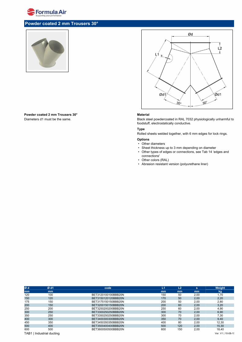
TAB1 | Industrial ducting Ver. V1 | 10-08-15
Powder coated 2 mm Trousers 30°Diameters d1 must be the same.
MaterialBlack steel powdercoated in RAL 7032 physiologically unharmful to foodstuff, electrostatically conductive.
TypeRolled sheets welded together, with 6 mm edges for lock rings.
Options• Other diameters• Sheet thickness up to 3 mm depending on diameter• Other types of edges or connections, see Tab 14 ‘edges and
connections'• Other colors (RAL)• Abrasion resistant version (polyurethane liner)
Powder coated 2 mm Trousers 30°
Ø d Ø d1 code L1 L2 s Weightmm mm mm mm mm kg120 100 BET3120100100BBB20N 150 50 2,00 1,70150 120 BET3150120120BBB20N 170 50 2,00 2,20175 150 BET3175150150BBB20N 200 50 2,00 2,80200 150 BET3200150150BBB20N 200 60 2,00 3,20250 200 BET3250200200BBB20N 250 60 2,00 4,90300 250 BET3300250250BBB20N 300 70 2,00 6,90350 250 BET3350250250BBB20N 300 70 2,00 7,30400 300 BET3400300300BBB20N 350 70 2,00 9,40450 350 BET3450350350BBB20N 400 80 2,00 12,30500 400 BET3500400400BBB20N 500 120 2,00 15,30600 500 BET3600500500BBB20N 600 150 2,00 18,40
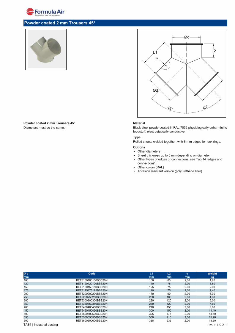
TAB1 | Industrial ducting Ver. V1 | 10-08-15
Powder coated 2 mm Trousers 45°Diameters must be the same.
MaterialBlack steel powdercoated in RAL 7032 physiologically unharmful to foodstuff, electrostatically conductive.
TypeRolled sheets welded together, with 6 mm edges for lock rings.
Options• Other diameters• Sheet thickness up to 3 mm depending on diameter• Other types of edges or connections, see Tab 14 ‘edges and
connections'• Other colors (RAL)• Abrasion resistant version (polyurethane liner)
Powder coated 2 mm Trousers 45°
Ø d Code L1 L2 s Weightmm mm mm mm kg100 BET5100100100BBB20N 100 60 2,00 1,20120 BET5120120120BBB20N 110 75 2,00 1,60150 BET5150150150BBB20N 125 75 2,00 2,00175 BET5175175175BBB20N 140 75 2,00 2,40200 BET5200200200BBB20N 170 90 2,00 3,30250 BET5250250250BBB20N 200 100 2,00 4,60300 BET5300300300BBB20N 220 120 2,00 6,00350 BET5350350350BBB20N 250 120 2,00 7,60400 BET5400400400BBB20N 270 150 2,00 9,60450 BET5450450450BBB20N 300 150 2,00 11,40500 BET5500500500BBB20N 325 175 2,00 13,50550 BET5550550550BBB20N 360 210 2,00 15,70600 BET5600600600BBB20N 385 235 2,00 18,50

TAB1 | Industrial ducting Ver. V1 | 10-08-15
Powder coated tapersThe tapers are produced from rolled sheets welded longitudinally. They are designed for a smooth transition between different diameters.
MaterialBlack steel powdercoated in RAL 7032 physiologically unharmful to foodstuff, electrostatically conductive.
TypeRolled sheets with 6 mm edges for lock rings.
Options• Other diameters• Other lengths• Sheet thickness up to 3 mm depending on diameter• Asymmetrical version• Other types of edges or connections, see Tab 14 ‘edges and
connections’• Abrasion resistant version (polyurethane liner)
Powder coated tapers
Ø d1 Ø d2 Code S L Weightmm mm mm mm kg120 100 BT120100BB20N 2,00 60 0,50150 100 BT150100BB20N 2,00 95 0,70150 120 BT150120BB20N 2,00 150 1,15175 120 BT175120BB20N 2,00 100 0,90175 150 BT175150BB20N 2,00 80 0,80200 100 BT200100BB20N 2,00 120 1,10200 120 BT200120BB20N 2,00 120 1,20200 150 BT200150BB20N 2,00 100 1,00200 175 BT200175BB20N 2,00 100 1,10250 120 BT250120BB20N 2,00 150 1,70250 150 BT250150BB20N 2,00 120 1,50250 200 BT250200BB20N 2,00 120 1,60300 150 BT300150BB20N 2,00 200 2,60300 200 BT300200BB20N 2,00 150 2,20300 250 BT300250BB20N 2,00 150 2,30350 300 BT350300BB20N 2,00 200 3,50400 300 BT400300BB20N 2,00 200 3,90400 350 BT400350BB20N 2,00 200 4,00450 350 BT450350BB20N 2,00 200 4,40450 400 BT450400BB20N 2,00 200 4,60500 400 BT500400BB20N 2,00 250 6,00500 450 BT500450BB20N 2,00 200 5,10550 450 BT550450BB20N 2,00 250 6,70550 500 BT550500BB20N 2,00 250 7,00600 500 BT600500BB20N 2,00 300 8,80600 550 BT600550BB20N 2,00 300 9,00

TAB1 | Industrial ducting Ver. V2 | 30-01-15
Black steel welding ends BCWThe welding ends are used at the start of a ducting system; for example on machinery, filter installations, screw conveyors, etc.
MaterialBlack steel.
TypeWith a 8 mm edge for all types of lock rings.
Options• Diameters > Ø 600 mm• Sheet thickness up to 3 mm, depending on diameter• Painted version (RAL 7032)
Black steel welding ends
Ø Code Ø d L s Weightmm mm mm mm kg80 BCW080 77 55 2.00 0.15100 BCW100 99 55 2.00 0.20120 BCW120 119 55 2.00 0.31125 BCW125 124 55 2.00 0.35140 BCW140 139 55 2.00 0.40150 BCW150 149 55 2.00 0.45160 BCW160 159 55 2.00 0.50180 BCW180 179 55 2.00 0.55200 BCW200 199 55 2.00 0.61220 BCW220 219 55 2.00 0.65225 BCW225 224 55 2.00 0.67250 BCW250 249 55 2.00 0.76275 BCW275 274 55 2.00 0.80280 BCW280 279 55 2.00 0.85300 BCW300 299 55 2.00 0.91315 BCW315 314 55 2.00 0.95350 BCW350 349 55 2.00 1.01355 BCW355 354 55 2.00 1.02400 BCW400 398 55 2.00 1.21450 BCW450 448 55 2.00 1.30500 BCW500 498 55 2.00 1.52550 BCW550 549 55 2.00 1.67560 BCW560 558 55 2.00 1.69600 BCW600 598 55 2.00 1.76630 BCW630 628 55 2.00 1.90

TAB1 | Industrial ducting Ver. V2 | 30-07-15
Manual trouser diverters 60° - without sealThe diverters are standard welded and externally powder coated in RAL 5010.Application for falling transport and light pneumatic transport (for example wood chips, polystyrene (PS), etc.).The inner plate is mounted with two ball bearings for smooth running.
MaterialSt. 37.2, painted RAL 5010
TypeCut sheets, full welded together, with 6 mm edges for lock rings.Extra side reinforcements from Ø 500 mm and up
Options• With seal• Other colours (RAL)• Other diameters• Other types of edges or connections, see Tab 14 ‘edges and
connections'
Manual trouser diverters 60° - without seal
Ø d code L1 L2 L3 s1 s2mm mm mm mm mm mm100 BNSMSOB100 365 108 278 2.00 3.00120 BNSMSOB120 365 108 278 2.00 3.00125 BNSMSOB125 365 108 278 2.00 3.00140 BNSMSOB140 490 150 354 2.00 3.00150 BNSMSOB150 490 150 354 2.00 3.00160 BNSMSOB160 490 150 354 2.00 3.00180 BNSMSOB180 545 150 395 2.00 3.00200 BNSMSOB200 545 150 395 2.00 3.00225 BNSMSOB225 815 250 450 2.00 3.00250 BNSMSOB250 815 250 450 2.00 3.00275 BNSMSOB275 920 250 500 2.00 3.00300 BNSMSOB300 920 250 500 2.00 3.00315 BNSMSOB315 960 250 550 2.00 3.00350 BNSMSOB350 960 250 550 2.00 3.00400 BNSMSOB400 1135 300 600 2.00 3.00450 BNSMSOB450 1195 300 650 2.00 3.00500 BNSMSOB500 1360 350 710 2.00 3.00550 BNSMSOB550 1385 350 750 2.00 3.00600 BNSMSOB600 1645 400 840 2.00 3.00630 BNSMSOB630 1645 400 840 2.00 3.00650 BNSMSOB650 1675 400 860 2.00 3.00700 BNSMSOB700 1760 400 920 3.00 3.00

TAB1 | Industrial ducting Ver. V2 | 30-07-15
Manual branch diverters 45° - without sealThe diverters are standard welded and externally powder coated in RAL 5010.Application for falling transport and light pneumatic transport (for example wood chips, polystyrene (PS), etc.).The inner plate is mounted with two ball bearings for smooth running.
MaterialSt. 37.2, painted RAL 5010
TypeCut sheets, full welded together, with 6 mm edges for lock rings.Extra side reinforcements from Ø 500 mm and up
Options• With seal• Other colours (RAL)• Other diameters• Other types of edges or connections, see Tab 14 ‘edges and
connections'
Specify when ordering: left (L) or right (R) type.
Manual branch diverters 45° - without seal
Ø d code L1 L2 L3 s1 s2mm mm mm mm mm mm100 BNSMxOC100 390 108 278 2.00 3.00120 BNSMxOC120 390 108 278 2.00 3.00125 BNSMxOC125 390 108 278 2.00 3.00140 BNSMxOC140 505 150 354 2.00 3.00150 BNSMxOC150 505 150 354 2.00 3.00160 BNSMxOC160 505 150 354 2.00 3.00180 BNSMxOC180 570 150 395 2.00 3.00200 BNSMxOC200 570 150 395 2.00 3.00225 BNSMxOC225 850 250 450 2.00 3.00250 BNSMxOC250 850 250 450 2.00 3.00275 BNSMxOC275 930 250 500 2.00 3.00300 BNSMxOC300 930 250 500 2.00 3.00315 BNSMxOC315 1000 250 550 2.00 3.00350 BNSMxOC350 1000 250 550 2.00 3.00400 BNSMxOC400 1175 300 600 2.00 3.00450 BNSMxOC450 1235 300 650 2.00 3.00500 BNSMxOC500 1410 350 710 2.00 3.00550 BNSMxOC550 1475 350 750 2.00 3.00600 BNSMxOC600 1695 400 840 2.00 3.00630 BNSMxOC630 1695 400 840 2.00 3.00650 BNSMxOC650 1715 400 860 2.00 3.00700 BNSMxOC700 1780 400 920 3.00 3.00

TAB1 | Industrial ducting Ver. V3 | 24-11-17
Pneumatic trouser diverters symmetrical 60° - without sealingThe diverters are standard welded and externally powder coated in RAL 5010.Application for falling transport and light pneumatic transport (for example wood chips, polystyrene (PS), etc.).Diverter is controlled by means of a pneumatic stroke cylinder.The inner plate is mounted with two ball bearings for smooth running.
MaterialSt. 37.2, painted RAL 5010
TypeCut sheets, full welded together, with 6 mm edges for lock rings.Extra side reinforcements from Ø 500 mm and up
Options• With seal• Protection house• Other colours (RAL)• Other diameters• With position detectors• Other types of edges or connections, see Tab 14 ‘edges and
connections'
Please state the voltage when ordering: 24 V AC, 24 V DC, 220 V AC.
Connection of a linear pneumatic cylinder for pneumatic diverters.
Pneumatic trouser diverters symmetrical 60° - without sealing
Ø d code L1 L2 L3 L4 s1 s2mm mm mm mm mm mm mm100 BNSPSO6100 365 108 250 500120 BNSPSO6120 365 108 250 500125 BNSPSO6125 365 108 250 500140 BNSPSO6140 490 150 299 610150 BNSPSO6150 490 150 299 610160 BNSPSO6160 490 150 299 610180 BNSPSO6180 545 150 343 750200 BNSPSO6200 545 150 343 750225 BNSPSO6225 815 250 393 752250 BNSPSO6250 815 250 393 752275 BNSPSO6275 920 250 450 755300 BNSPSO6300 920 250 450 755315 BNSPSO6315 960 250 495 840350 BNSPSO6350 960 250 495 840400 BNSPSO6400 1135 300 545 895450 BNSPSO6450 1195 300 592 895500 BNSPSO6500 1360 350 655 905550 BNSPSO6550 1385 350 695 952600 BNSPSO6600 1645 400 810 975630 BNSPSO6630 1645 400 810 975650 BNSPSO6650 1675 400 830 995700 BNSPSO6700 1760 400 880 1060
2.002.002.002.002.002.002.002.002.002.002.002.002.002.002.002.002.002.002.002.002.003.00
3.003.003.003.003.003.003.003.003.003.003.003.003.003.003.003.003.003.003.003.003.003.00
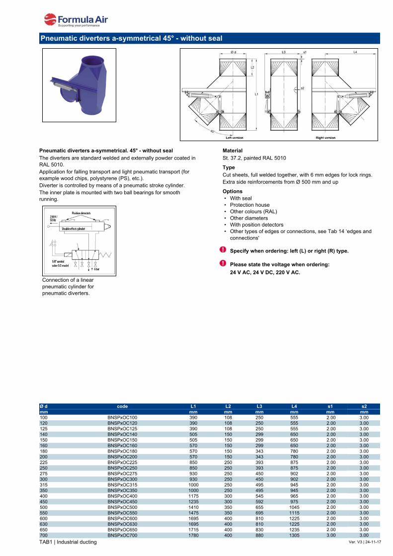
TAB1 | Industrial ducting Ver. V3 | 24-11-17
Pneumatic diverters a-symmetrical. 45° - without sealThe diverters are standard welded and externally powder coated in RAL 5010.Application for falling transport and light pneumatic transport (for example wood chips, polystyrene (PS), etc.).Diverter is controlled by means of a pneumatic stroke cylinder.The inner plate is mounted with two ball bearings for smooth running.
MaterialSt. 37.2, painted RAL 5010
TypeCut sheets, full welded together, with 6 mm edges for lock rings.Extra side reinforcements from Ø 500 mm and up
Options• With seal• Protection house• Other colours (RAL)• Other diameters• With position detectors• Other types of edges or connections, see Tab 14 ‘edges and
connections'
Specify when ordering: left (L) or right (R) type.
Please state the voltage when ordering: 24 V AC, 24 V DC, 220 V AC.
Connection of a linear pneumatic cylinder for pneumatic diverters.
Pneumatic diverters a-symmetrical 45° - without seal
Ø d code L1 L2 L3 L4 s1 s2mm mm mm mm mm mm mm100 BNSPxOC100 390 108 250 555120 BNSPxOC120 390 108 250 555125 BNSPxOC125 390 108 250 555140 BNSPxOC140 505 150 299 650150 BNSPxOC150 505 150 299 650160 BNSPxOC160 570 150 299 650180 BNSPxOC180 570 150 343 780200 BNSPxOC200 570 150 343 780225 BNSPxOC225 850 250 393 875250 BNSPxOC250 850 250 393 875275 BNSPxOC275 930 250 450 902300 BNSPxOC300 930 250 450 902315 BNSPxOC315 1000 250 495 945350 BNSPxOC350 1000 250 495 945400 BNSPxOC400 1175 300 545 965450 BNSPxOC450 1235 300 592 975500 BNSPxOC500 1410 350 655 1045550 BNSPxOC550 1475 350 695 1115600 BNSPxOC600 1695 400 810 1225630 BNSPxOC630 1695 400 810 1225650 BNSPxOC650 1715 400 830 1235700 BNSPxOC700 1780 400 880 1305
2.002.002.002.002.002.002.002.002.002.002.002.002.002.002.002.002.002.002.002.002.003.00
3.003.003.003.003.003.003.003.003.003.003.003.003.003.003.003.003.003.003.003.003.003.00
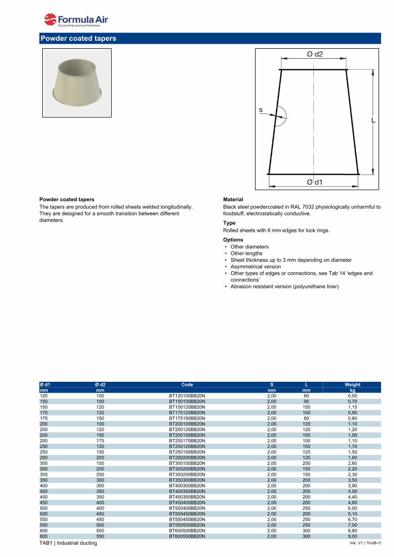
TAB1 | Industrial ducting Ver. V1 | 10-08-15
Powder coated tapersThe tapers are produced from rolled sheets welded longitudinally. They are designed for a smooth transition between different diameters.
MaterialBlack steel powdercoated in RAL 7032 physiologically unharmful to foodstuff, electrostatically conductive.
TypeRolled sheets with 6 mm edges for lock rings.
Options• Other diameters• Other lengths• Sheet thickness up to 3 mm depending on diameter• Asymmetrical version• Other types of edges or connections, see Tab 14 ‘edges and
connections’• Abrasion resistant version (polyurethane liner)
Powder coated tapers
Ø d1 Ø d2 Code S L Weightmm mm mm mm kg120 100 BT120100BB20N 2,00 60 0,50150 100 BT150100BB20N 2,00 95 0,70150 120 BT150120BB20N 2,00 150 1,15175 120 BT175120BB20N 2,00 100 0,90175 150 BT175150BB20N 2,00 80 0,80200 100 BT200100BB20N 2,00 120 1,10200 120 BT200120BB20N 2,00 120 1,20200 150 BT200150BB20N 2,00 100 1,00200 175 BT200175BB20N 2,00 100 1,10250 120 BT250120BB20N 2,00 150 1,70250 150 BT250150BB20N 2,00 120 1,50250 200 BT250200BB20N 2,00 120 1,60300 150 BT300150BB20N 2,00 200 2,60300 200 BT300200BB20N 2,00 150 2,20300 250 BT300250BB20N 2,00 150 2,30350 300 BT350300BB20N 2,00 200 3,50400 300 BT400300BB20N 2,00 200 3,90400 350 BT400350BB20N 2,00 200 4,00450 350 BT450350BB20N 2,00 200 4,40450 400 BT450400BB20N 2,00 200 4,60500 400 BT500400BB20N 2,00 250 6,00500 450 BT500450BB20N 2,00 200 5,10550 450 BT550450BB20N 2,00 250 6,70550 500 BT550500BB20N 2,00 250 7,00600 500 BT600500BB20N 2,00 300 8,80600 550 BT600550BB20N 2,00 300 9,00

TAB1 | Industrial ducting Ver. V1 | 22-10-15
Powder coated transition piece MaterialBlack steel powdercoated in RAL 7032 physiologically unharmful to foodstuff, electrostatically conductive.
TypeRolled sheets with 6 mm edges for lock rings.
Options• Other diameters• Sheet thickness up to 3 mm depending on diameter• Asymmetrical version• Other types of edges or connections, see Tab 14 ‘edges and
connections’• Abrasion resistant version (polyurethane liner)
Powder coated transition piece
Ø d Code L1 L2 L3 L4 d smm mm mm mm mm mm mm100 BU120120D100A20N 60 120 160 140 6 2,00120 BU140140D120A20N 70 140 180 164 6 2,00150 BU180180D150A20N 85 180 220 202 6 2,00175 BU200200D175A20N 145 200 245 225 6 2,00200 BU250250D200A20N 135 250 290 270 6 2,00250 BU300300D250A20N 150 300 345 325 6 2,00300 BU350350D300A20N 210 350 395 375 6 2,00