X20IF1043-1 - B&R Industrial Automation
14
X20IF1043-1 X20IF1043-1 1 General information The interface module is equipped with a CANopen (slave) interface. This allows the B&R system (I/O modules, POWERLINK, etc.) to be connected to systems from other manufacturers and makes it possible to quickly and easily transfer data in both directions. The interface module can be operated in X20 CPUs or in the expandable POWERLINK bus controller X20BC1083. • CANopen slave • Integrated terminating resistor 2 Order data Order number Short description Figure X20 interface module communication X20IF1043-1 X20 interface module, for DTM configuration, 1 CANopen slave interface, electrically isolated, order 1x terminal block TB2105 separately! Required accessories Terminal blocks 0TB2105.9010 Accessory terminal block, 5-pin, screw clamps 2.5 mm² 0TB2105.9110 Accessory terminal block, 5-pin, push-in terminal block 2.5 mm² Table 1: X20IF1043-1 - Order data Data sheet V 2.07 1
-
Upload
khangminh22 -
Category
Documents
-
view
1 -
download
0
Transcript of X20IF1043-1 - B&R Industrial Automation

X20IF1043-1
X20IF1043-1
1 General information
The interface module is equipped with a CANopen (slave) interface. This allows the B&R system (I/O modules,POWERLINK, etc.) to be connected to systems from other manufacturers and makes it possible to quickly andeasily transfer data in both directions.The interface module can be operated in X20 CPUs or in the expandable POWERLINK bus controller X20BC1083.
• CANopen slave• Integrated terminating resistor
2 Order dataOrder number Short description Figure
X20 interface module communicationX20IF1043-1 X20 interface module, for DTM configuration, 1 CANopen slave
interface, electrically isolated, order 1x terminal block TB2105separately!Required accessoriesTerminal blocks
0TB2105.9010 Accessory terminal block, 5-pin, screw clamps 2.5 mm²0TB2105.9110 Accessory terminal block, 5-pin, push-in terminal block 2.5 mm²
Table 1: X20IF1043-1 - Order data
Data sheet V 2.07 1
X20IF1043-1
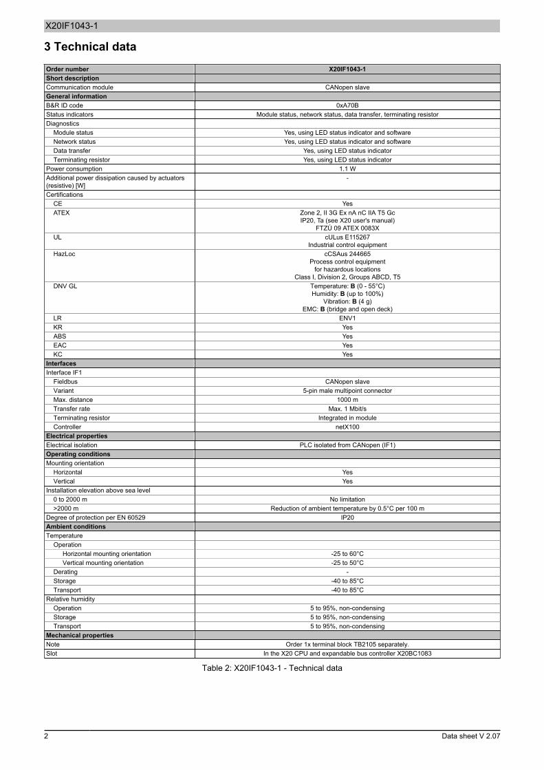
3 Technical dataOrder number X20IF1043-1Short descriptionCommunication module CANopen slaveGeneral informationB&R ID code 0xA70BStatus indicators Module status, network status, data transfer, terminating resistorDiagnostics
Module status Yes, using LED status indicator and softwareNetwork status Yes, using LED status indicator and softwareData transfer Yes, using LED status indicatorTerminating resistor Yes, using LED status indicator
Power consumption 1.1 WAdditional power dissipation caused by actuators(resistive) [W]
-
CertificationsCE YesATEX Zone 2, II 3G Ex nA nC IIA T5 Gc
IP20, Ta (see X20 user's manual)FTZÚ 09 ATEX 0083X
UL cULus E115267Industrial control equipment
HazLoc cCSAus 244665Process control equipment
for hazardous locationsClass I, Division 2, Groups ABCD, T5
DNV GL Temperature: B (0 - 55°C)Humidity: B (up to 100%)
Vibration: B (4 g)EMC: B (bridge and open deck)
LR ENV1KR YesABS YesEAC YesKC Yes
InterfacesInterface IF1
Fieldbus CANopen slaveVariant 5-pin male multipoint connectorMax. distance 1000 mTransfer rate Max. 1 Mbit/sTerminating resistor Integrated in moduleController netX100
Electrical propertiesElectrical isolation PLC isolated from CANopen (IF1)Operating conditionsMounting orientation
Horizontal YesVertical Yes
Installation elevation above sea level0 to 2000 m No limitation>2000 m Reduction of ambient temperature by 0.5°C per 100 m
Degree of protection per EN 60529 IP20Ambient conditionsTemperature
OperationHorizontal mounting orientation -25 to 60°CVertical mounting orientation -25 to 50°C
Derating -Storage -40 to 85°CTransport -40 to 85°C
Relative humidityOperation 5 to 95%, non-condensingStorage 5 to 95%, non-condensingTransport 5 to 95%, non-condensing
Mechanical propertiesNote Order 1x terminal block TB2105 separately.Slot In the X20 CPU and expandable bus controller X20BC1083
Table 2: X20IF1043-1 - Technical data
2 Data sheet V 2.07

X20IF1043-1
4 Operating and connection elements
1
2
3
1 IF1 - CANopen 2 LED status indicators3 Switch for terminating resistor on the bottom of the module 4 -
4.1 LED status indicators
Figure LED Color Status DescriptionGreen/red Off No power to moduleGreen On PCI bus communication in progress
Blinking Error when booting
READY/RUN
RedOn Communication on the PCI bus has not yet been startedOff Module executes a resetBlinking greenRed double flash
The module is in mode "PREOPERATIONAL".CANopen communication has a disturbance. Possible causes:
• The CAN bus cable has been disconnected or the CAN bus con-troller is in "Bus off" mode.
• Heartbeat or monitoring event occurredBlinking greenRed single flash
The module is in mode "PREOPERATIONAL".The CAN error counter has reached or exceeded the warning limit; e.g.too many error frames.
ERR/RUN Green/red
Green single flashRed double flash
The module is in mode "STOPPED".CANopen communication was stopped. Possible causes:
• Heartbeat or monitoring event occurredTxD Yellow Flickering or on Module sending data via the CANopen interface
TERM Yellow On Terminating resistor integrated in the module switched on
LED blinking diagram
Blinking
Single flash
Double flash
4.2 CAN bus interface
The interface is a 5-pin multipoint connector. Terminal block 0TB2105 must be ordered separately.Interface Pinout
Terminal Function1 CAN⊥ CAN ground2 CAN_L CAN low3 SHLD Shield4 CAN_H CAN high5 NC
1
5
5-pin male multipoint connector
Data sheet V 2.07 3

X20IF1043-1
4.3 Terminating resistor
On Off
Switch for terminating resistor
A terminating resistor is integrated in the interface module. It can be switched on or off with a switch on the bottomof the housing. A switched-on terminating resistor is indicated by LED "TERM".
5 Use in the expandable X20BC1083 POWERLINK bus controller
5.1 Cyclic data
If this module is connected to the expandable POWERLINK bus controller, the amount of cyclic data is limited bythe POWERLINK frame to 1488 bytes in each direction (input and output).When using multiple X20IF10xx-1 interfaces or other X2X modules with a POWERLINK bus controller, the 1488bytes are divided between all connected modules.
5.2 Operating netX modules
It is important to note the following in order to operate netX modules with the bus controller without problems:
• A minimum revision ≥ E0 is required for the bus controller.• netX modules can only be operated with the POWERLINK V2 setting. V1 is not permitted.• With SDO access to POWERLINK object 0x1011/1 on the bus controller, the netX firmware and the con-
figuration stored on the bus controller are not reset. They can only be overwritten by accessing them again.This affects objects 0x20C0 and 0x20C8, subindexes 92 to 95.
5.3 Timing characteristics
The internal data transfer results in an additional runtime shift of one cycle per direction.
Information:For additional information about runtime behavior, see section "Runtime shift" in X20BC1083.
6 netX error codes
netX modules return an error code when an error occurs. These error codes are fieldbus-specific. A complete listof all error codes in PDF format is available in Automation Help in section "Communication / Fieldbus systems /Support with FDT/DTM / Diagnostic functions / Diagnostics on the runtime system / Master diagnostics" under item"Communication_Error".
7 Firmware
The module comes with preinstalled firmware. The firmware is part of the Automation Studio project. The moduleis automatically brought up to this level.To update the firmware contained in Automation Studio, a hardware upgrade must be performed (see "Projectmanagement / Workspace / Upgrades" in Automation Help).
4 Data sheet V 2.07

X20IF1043-1
8 The CANopen interface
Information:The settings on the slave must match the settings of the corresponding device description file; other-wise, no connection can be established.
8.1 Settings in Automation Studio
The interface module can be operated in the slot of a CPU or in the slot of an expandable POWERLINK buscontroller.To do this, a new Automation Studio project is created and the suitable settings are made on the module.
8.1.1 Creating an Automation Studio project
● Create a new Automation Studio project by selecting "New project".
● Assign a project name and set up the project path.
● Assign the hardware configuration type and configuration name.
Data sheet V 2.07 5

X20IF1043-1
● Select the hardware in the next step if "Define a new hardware configuration manually" was selected.In order to simplify the search, different filters can be set in the Hardware Catalog. Lastly, highlight the requiredhardware and create the Automation Studio project by clicking on "Finish".
8.1.2 Adding and configuring the interface module
● In this example, the interface card is connected in the slot of a CPU. Right-clicking on the slot and selecting "Addhardware module" opens the Hardware Catalog.
● The module is added to the project via drag-and-drop or by double-clicking on the interface card.
● Additional module settings can be made under "Device configuration". This configuration environment is openedby right-clicking on the IF interface and selecting "Device configuration".
6 Data sheet V 2.07

X20IF1043-1
● General settings are made in the device configuration.
8.1.2.1 General
- Bus parametersThe NodeID and baud rate can be configured here.These values from the EDS description file on the master can only be read.Parameter Explanation ValuesNode ID The node ID is used in CANopen for addressing and each ID is only permitted to occur
once in a network.
The same node ID must be set in the EDS description file on the master andslave.
1 to 127
Baud rate Sets the transfer rate 10 kbit/s to 1 Mbit/sEnable address switch This parameter is not supported.
- Application monitoringThe module-internal watchdog time can be set here. If the watchdog has been enabled (watchdog time not equalto 0), the hardware watchdog must be reset after the set time at the latest.Parameter Explanation Values
Watchdog software disabled 0 msWatchdog timePermissible range of valuesDefault value: 1000 ms
20 to 65535 ms
Information:The watchdog time is reset automatically by Automation Runtime.
Data sheet V 2.07 7

X20IF1043-1
- Start of bus communicationIt is possible to select how data exchange is started on the module.Parameter ExplanationAutomatically by device Data exchange is started automatically after initializing this module.Controlled by application Data exchange is started by Automation Runtime.
Information:Parameter "Manual start of bus communication" can be enabled under the I/O configuration of theCANopen slave.
The following settings must be made in order to avoid automatic data exchange:
• In the IF module configuration, "Manual start of bus communication" must be set to "On".• "Start of bus communication" must be set to "Controlled by application".
With this setting, communication can only be started via function block AsNxCoS - nxcosStartBusComm().- DeviceThis data is read from the EDS file (DTM) and not configurable.- VendorThis data is read from the EDS file (DTM) and not configurable.
8.1.2.2 Special function objects
The receipt of EMCY messages and transmission of SYNC messages can be set here. However, these settingscan only be configured in the device description file on the master.- Synchronization messageWhether the slave generates the SYNC messages can be set here.
Information:On the slave, this setting causes an error message and is therefore not permitted to be used.
Parameter ExplanationDevice generates SYNC message Enabling generation of the SYNC message
No other parameters are supported.- TimeStamp messageThis parameter is not supported.- Emergency messageWhether the master can receive EMCY messages can be set here.Parameter ExplanationEMCY exists Master can receive EMCY messages
No other parameters are supported.
8 Data sheet V 2.07

X20IF1043-1
8.1.2.3 Object dictionary
The object dictionary of the device is listed here. These are taken from the EDS file (DTM). PDO objects can beenabled or disabled in the object dictionary. This is done under "Process data objects - Properties" on page 9.The object dictionary can be filtered with "Area" and "Status"; using "Object", a single object can be searched.
Object dictionaryParameter Explanation ValuesConfigure Overview of the configuration options.
• Key symbol: Entry cannot be configured in the object dictionary.• Checkbox with check mark: Object can be configured.• Checkbox without check mark: Object is locked for the configuration.
Index.Subindex Object address consisting of index and subindexName Symbolic name of the deviceAccess Access rights of the device • RO - Read only
• RW - Read and write• WO - Write only• CONST - Constant
value
When a specific object is selected in the object dictionary, the name, current value, default value, data type andminimum/maximum values of the object are listed. This listing can be in decimal and hexadecimal notation.
8.1.2.4 Process data objects - Properties
Additional PDOs can be enabled here. Each additional PDO enabled is listed under "Process data objects →Mapping → PDO contents mapping for" and in the I/O mapping. The first 4 PDOs (0x1400 to 0x1404 for RxPDOand 0x1800 to 0x1804 for TxPDO) are enabled by default. To update the I/O mapping, additional PDOs must beenabled.The PDO type can be used to toggle between transmit PDOs (TPDO) and receive PDOs (RPDO).Parameter ExplanationConfigure Enables or disables a PDO for configuration and communicationIndex Object index of the PDOPDO name Name of the PDO
If a PDO is selected in the table, the properties of the PDO are listed under the table.- COB IDThe COB ID consists of the CAN identifier and additional parameters for the corresponding communication object.Parameter Explanation ValuesCAN ID CAN identifier of the object. 1 to 2047PDO exists This parameter is identical to enabling the PDOs in the table under "Configure". If this
parameter was enabled, the affected PDO is present in the mapping.By default, only the first 4 PDOs are enabled.
RTR permitted If selected, the message trigger mode "Remotely requested" is permitted for this PDO.This means that when an RTR triggered by a PDO consumer is received, the transfer ofan event-controlled PDO is triggered.Otherwise, message trigger mode "Remotely requested" is not permitted for this PDO.The value from the EDS file is applied as the default value.
An RTR is not permitted to be used to query a transfer of emergency objects.
29-bit This parameter is not supported.
Data sheet V 2.07 9

X20IF1043-1
- TransmissionThe transfer type and rate are defined here.Parameter Explanation ValuesTransmission type For the transmit or receive PDOs, different transfer types are possible. A PDO can be
configured for an event-driven, synchronous or asynchronous transfer. Transfer typescan be synchronized, e.g. to the synchronization message SYNC, which is transmittedby the master in defined time intervals. Synchronous means that the transfer of the PDOsis related to the synchronization message. Asynchronous means that the transfer of thePDOs is not related to the SYNC synchronization message and can be executed at anytime.
Support for the different transfer types depends on the manufacturer and de-vice. CANopen does not require support from individual or all transfer types.For information about whether a device supports the desired transfer type,check the device description of the device used.
Synchronous acyclic (0)Synchronous cyclic (1 to 240)Event-controlled, manufactur-er-specific (254)Event controlled, profile-specif-ic (255)
Transmission rate For synchronous TPDOs, a number must be specified for transfer type "Synchronouscyclic (1 to 240)" to which the SYNC message of the data transfer refers.
• A SYNC number of 1 indicates that the message is transferred with each SYNCsynchronization message.
• A SYNC number of n indicates that the message is transferred with every nthSYNC synchronization message.
Asynchronous TPDOs are not transferred in any timing relationship with a SYNC syn-chronization message.
1 to 240
Inhibit time It describes the minimum time period that must elapse between the sending of identicalmessages. This suppresses sending identical messages too frequently.This parameter is not supported.
Event timer Only for TPDOs transfer types 254 and 255. The expiration of the timer is used as anevent to transmit the TPDO. Transmitting the TPDO and resetting the event timer canalso be caused by an application event, however.This parameter is not supported.
8.1.2.5 Process data objects - Mapping
The mapping can be configured here.The PDO type can be used to toggle between transmit PDOs (TPDO) and receive PDOs (RPDO).The table is divided into two parts. All usable objects are listed in the upper part. The lower part contains a listof the objects that have already been added to the mapping. It is added to the mapping by double-clicking on aPDO in the upper table.Parameter ExplanationIndex.Subindex Index or subindex of the relevant object.Parameter Name of the objectData type Data type of the objectLength Length of the PDO in bytesAccess PDO access right
The enabled PDOs can be toggled under "PDO contents mapping for". A maximum of 8 bytes, i.e. 64 bits, canbe mapped in a PDO.
Information:The number of mappable PDOs is limited. As soon as the limit has been reached, either an object mustbe removed or additional PDOs must be enabled under "Process data objects - Properties" on page9.
10 Data sheet V 2.07

X20IF1043-1
8.1.2.6 Address table
Contains a list of all PDOs that are categorized according to their inputs and outputs. The respective length of theinputs and outputs as well as the assigned address can be read in this table.This table is not available in the EDS description file on the master."Display mode" allows toggling between decimal and hexadecimal display.Parameter ExplanationPDO-Name The RxPDO name or TxPDO name is displayed here. These are defined in the EDS file.PDO-Idx Object index of the process data object (PDO)COB ID COB ID of the CAN messageObj.Idx Subidx All objects are addressed in the object index and, if applicable, in the associated sub-indexes defined by the
EDS file.Obj.Name Object nameType Type of input or output dataLength Length of the input or output data of the PDO in bytesAddress Offset address of the input or output data
The address table can also be exported as a CSV file.
8.1.2.7 Device description
General device information and the entire EDS file can be read here.
8.2 EDS device description file
The module description is made available to the master in an EDS file. This file contains the description of the slave'scomplete range of functions. The EDS file can be downloaded from the B&R website (www.br-automation.com) inthe Downloads section for the interface module and then imported into the respective master environment.
Data sheet V 2.07 11

X20IF1043-1
8.3 Configuration example
● In this example, the PDO mapping should be configured to 40 input bytes and 20 output bytes. "Device config-uration" on the CANopen slave is opened for this.
● The number of RPDOs and TPDOs that must be applied is defined under "Process data objects → Properties".8 bytes of data can be transferred per PDO. The minimum number of RPDOs and TPDOs is always 4, even ifless data should be transferred.RPDOFor 40 byte input data, 5 RPDOs are selected.
TPDOTo configure the TPDOs, "TPDO" is selected as the PDO type. Since only 20 bytes should be transferred, thedefault setting of 4 PDOs remains unchanged.
● The type of data transfer is defined (cyclic, acyclic, event-driven, etc.) under "Transmission type". For this exam-ple, the PDOs are transferred as "event-driven", i.e. only when data is changed.
● The PDOs are filled under "Process data objects → Mapping". The configured RPDOs are listed under "PDOcontents mapping for"; in this example, they are listed as RPDO 1 to RPDO 5.
By default, the PDOs are filled with bytes. No change must therefore be made for the input bytes.If a change is desired, RPDOs can be swapped out or data cut and pasted with "PDO contents mapping for".
12 Data sheet V 2.07

X20IF1043-1
CutSelect the desired object and cut it out with the scissors.
PasteDouble-clicking on an index in "Mappable objects" transfers the object to "Mapped objects".
● TPDOs are edited by changing to "TPDO" under "Filter PDO type". Bytes that are not required can be removedfrom the assignment. This is done by selecting the relevant TPDOs and cutting the superfluous objects using thescissors.Because only 20 output bytes are needed in this example, no bytes are mapped in TPDO4 and only 4 bytes inTPDO3.
Data sheet V 2.07 13

X20IF1043-1
● Configuring the device description fileIdentical settings must be made in the device description file. To do this, the device description file attached to themaster must be set identically to the device configuration and I/O mapping of the CANopen slave.If the setting on the CANopen slave and the device description file attached to the master do not match, no con-nection is established.
Information:The number of input and output bytes must be set identically on the master and slave. The directionof the data on the slave is applied in the direction opposite to the master since data exchange takesplace in the opposite direction.
In the following example, this means:
• Device description file on the master: 40 bytes in the output direction and 20 bytes in the input direction.• Slave: 40 bytes in the input direction and 20 bytes in the output direction.
14 Data sheet V 2.07