Dodge® Motorized Torque-Arm II - Apex Industrial Automation
67
G1-1 CONTENTS Gearing Reference Guide TORQUE-ARM II MOTORIZED TORQUE-ARM II TORQUE-ARM Engineering System-1 Part Number Index Dodge ® Motorized Torque-Arm II Accessories ................................................................................................................................G1-3 Easy Selection Method ..............................................................................................................G1-5 Determining Service Class ........................................................................................................G1-6 MTA2 - MTA8 Nomenclature and Descriptions .....................................................................G1-13 Engineering ...............................................................................................................................G1-15 EZ Selection HP & Speed Class I ................................................................................................................................ G1-22 Class II ............................................................................................................................... G1-26 EZ Selection Tables MTA2115H ......................................................................................................................... G1-30 MTA3203H ......................................................................................................................... G1-31 MTA4207H ......................................................................................................................... G1-32 MTA5215H ......................................................................................................................... G1-33 MTA6307H ......................................................................................................................... G1-34 MTA7315H ......................................................................................................................... G1-35 MTA8407H ......................................................................................................................... G1-36 Shaft Mounted Reducer and Accessories MTA2115 ............................................................................................................................ G1-37 MTA3203 ............................................................................................................................ G1-41 MTA4207 ............................................................................................................................ G1-45 MTA5215 ............................................................................................................................ G1-49 MTA6307 ............................................................................................................................ G1-53 MTA7315 ............................................................................................................................ G1-57 MTA8407 ............................................................................................................................ G1-61 Harsh Duty Accessories ..........................................................................................................G1-63 Aftermarket Replacement Parts ......................................................................................... G1-64 Mounting Positions ............................................................................................................ G1-65 Engineering/Technical Viscosity Classification Equivalents ................................................................................... G1-66 Lubrication of Motorized Torque-Arm II Reducers............................................................. G1-66
-
Upload
khangminh22 -
Category
Documents
-
view
2 -
download
0
Transcript of Dodge® Motorized Torque-Arm II - Apex Industrial Automation

G1-1
CONTENTS
Gea
ring
Refe
ren
ce
Gu
ide
TO
RQ
UE
-AR
M II
MO
TO
RIZ
ED
T
OR
QU
E-A
RM
IIT
OR
QU
E-A
RM
E
ng
ine
erin
gS
ystem-1
Pa
rt Nu
mb
er In
dex
Dodge® Motorized Torque-Arm II
Accessories ................................................................................................................................G1-3
Easy Selection Method ..............................................................................................................G1-5
Determining Service Class ........................................................................................................G1-6
MTA2 - MTA8 Nomenclature and Descriptions .....................................................................G1-13
Engineering ...............................................................................................................................G1-15
EZ Selection HP & Speed
Class I ................................................................................................................................G1-22
Class II ...............................................................................................................................G1-26
EZ Selection Tables
MTA2115H .........................................................................................................................G1-30
MTA3203H .........................................................................................................................G1-31
MTA4207H .........................................................................................................................G1-32
MTA5215H .........................................................................................................................G1-33
MTA6307H .........................................................................................................................G1-34
MTA7315H .........................................................................................................................G1-35
MTA8407H .........................................................................................................................G1-36
Shaft Mounted Reducer and Accessories
MTA2115 ............................................................................................................................G1-37
MTA3203 ............................................................................................................................G1-41
MTA4207 ............................................................................................................................G1-45
MTA5215 ............................................................................................................................G1-49
MTA6307 ............................................................................................................................G1-53
MTA7315 ............................................................................................................................G1-57
MTA8407 ............................................................................................................................G1-61
Harsh Duty Accessories ..........................................................................................................G1-63
Aftermarket Replacement Parts .........................................................................................G1-64
Mounting Positions ............................................................................................................G1-65
Engineering/Technical
Viscosity Classification Equivalents ...................................................................................G1-66
Lubrication of Motorized Torque-Arm II Reducers .............................................................G1-66

G1-2
DODGE® MOTORIZED TORQUE-ARM II
Pa
rt N
um
be
r In
dex
En
gin
ee
rin
gS
yste
m-1
TO
RQ
UE
-AR
M
TO
RQ
UE
-AR
M II
MO
TO
RIZ
ED
T
OR
QU
E-A
RM
IIG
eari
ng
Ref
ere
nc
e G
uid
e
With 60 years of proven dependability and more than 2 million units in service throughout the world, Dodge Torque-Arm speed reducers are the standard of the industry. Now, that legacy continues with the newest generation in shaft mounted speed reducers: The Dodge Motorized Torque-Arm II - offering patented innovations, new features, plus increased torque and horsepower ratings.
The Dodge Motorized Torque-Arm II surpasses other reducers on the market because of its industry proven design and patented features. This powerful line of shaft mounted speed reducers - in 7 case sizes with Class 2 rating through 100 horsepower (HP) - offers unparalleled torque ratings and is quickly becoming the new industry standard. Improved features include: an all-new backstop concept, a patented sealing system, a state-of-the-art, totally modular design with a patented twin tapered bushing system. The backstop design features a unique sprag profile for extended life and designed for use with lubricants containing EP additives. In addition, the Motorized Torque-Arm II line has a patented, premium sealing system that uses a Harsh Duty oil seal protected by a metal excluder seal with rubbing lip. This harsh duty sealing system makes this reducer series a perfect fit for today’s harsh duty industries such as aggregates, mining, cement, asphalt, mixing & milling and ethanol. Its patented twin tapered bushing system - in standard length, short shaft, and metric versions - offers all the features of our standard twin tapered Torque-Arm bushing design which are unique to Dodge. The patented insertable tapered wedge enables the optional extended tapered bushing kit to be applied for shorter shaft lengths, allowing the replacement of straight bore reducers.

G1-3
DODGE® MOTORIZED TORQUE-ARM II
Gea
ring
Refe
ren
ce
Gu
ide
TO
RQ
UE
-AR
M II
MO
TO
RIZ
ED
T
OR
QU
E-A
RM
IIT
OR
QU
E-A
RM
E
ng
ine
erin
gS
ystem-1
Pa
rt Nu
mb
er In
dex
AccessoriesMTA uses standard TA II accessories
Accessories
MTA Bushing Covers provide protection from the spinning bushing bolts and offer an added layer of contamination protection.
The MTA II is drilled and tapped for the Heavy Duty ABS covers. The Aluminum covers require customer modification of the gearbox to allow fitment.
The Screw Conveyor Driveshafts are made from high alloy steel and engineered To CEMA dimensions. They are three-bolt drilled and their tapered fit ensures simple installation. The rugged locking plate (patent pending) also provides a mechanical shaft removal feature. #316 Stainless Steel drive shafts also available.
Standard Twin Tapered Bushing Systemis an easy on, easy off, no-wobble bushing system featuring a fully split, ductile iron 8° taper and reliable twin support. Available in inch and metric bores. Increased bore capability in many sizes.
This new-design Backstop option helps prevent reverse rotation in high stop-start loads, and results in less wear and longer life. Its centrifugal sprag design operates with standard and EP lubricants and requires no external lubrication. NOTE: MTA II reducers require a larger backstop than equivalent TA II. See MTA II section for ALL MTA II accessories.
Ruggedly constructed, the TA Rod Kit includes standard Brackets and Offers universal mounting options.
The Cema Bolt-On Screw Conveyor Adapter features double-lip seals on both surfaces. The adapter center is open for contaminate drop out for optimized sealing.
An optional Adjustable Packing Kit bolts to the standard adapter and provides a proven sealing option for hostile environments. Packing can be retightened.
Our Short-Shaft Twin-Tapered Bushing Kits eliminate the need for full-length shafts. Constructed with ductile iron, it has all the Features of our standard bushing system. Available in both inch and metric bores.
AluminumABS Polymer

G1-4
DODGE® MOTORIZED TORQUE-ARM II
Pa
rt N
um
be
r In
dex
En
gin
ee
rin
gS
yste
m-1
TO
RQ
UE
-AR
M
TO
RQ
UE
-AR
M II
MO
TO
RIZ
ED
T
OR
QU
E-A
RM
IIG
eari
ng
Ref
ere
nc
e G
uid
e
Torque-Arm Family Breather Technology
1. Standard Breather is a filter breather • Cotton filter media • Screen to support filter • Chamber to allow oil to collect and return to reducer • Non captured filter (should not clog and block air exit)
1.
2. Hydra-Lock Desiccant Breather • Built in standpipe • 3 micron filter media top and bottom • Desiccant material changes color from blue (good) to pink (replace) • Check valve system, so breather is only open to atmosphere under pressure or vacuum. Closed when not running.
2.
3. Fully Enclosed Canister Breather • Allows no outside air • Excellent protections for extreme wet environments
3.
4.
4. Optional Position D Breather Kit • Use when reducer is mounted in position D (G1-65) • Includes: Enclosed Breather, sight glass, all necessary piping to allow for fitment to all sizes of MTA
Harsh Duty Breathers are available

G1-5
DODGE® MOTORIZED TORQUE-ARM II
Gea
ring
Refe
ren
ce
Gu
ide
TO
RQ
UE
-AR
M II
MO
TO
RIZ
ED
T
OR
QU
E-A
RM
IIT
OR
QU
E-A
RM
E
ng
ine
erin
gS
ystem-1
Pa
rt Nu
mb
er In
dex
Motorized Torque-Arm II Shaft Mount Speed ReducersEasy Selection Method (For Electric Motors) For Motorized Torque-Arm II Reducer And Screw Conveyor Drive Reducer Applications
Easy Selection Method
When to Use Easy SelectionThe Easy Selection tables for MTA II reducers are for electric motor selections up to 100 horsepower with output speeds up to ~150 RPM, using AGMA recommended application class numbers. For extreme shock or high energy loads which must be absorbed, as when stalling; for a power source other than an electric motor; or for extreme ambient temperatures or oversized equipment, consult Dodge Application Engineering, 864-284-5700.How to SelectStep 1: Determine Class of Service - See Table 1 to determine Load Classification for applications under normal conditions.Find the type application and duty cycle: Class 1 - Steady load not exceeding Motor HP rating and light shock loads during 10 hours a day. Moderate shock loads are allowable if operation is intermittent. For Class 1 applications, the maximum value of starting and momentary peak loads should not exceed 2 x Motor HP rating. If it exceeds this amount it should be divided by 2 and the result used in the selection table instead of the Motor HP rating. Class 2 - Steady load not exceeding Motor HP rating for over 10 hours a day. Moderate shock loads are allowable during 10 hours a day. For Class 2 applications, the maximum value of starting and momentary peak loads should not exceed 2.8 x Motor HP rating. If it exceeds this amount it should be divided by 2.8 and the result used in the selection table instead of the Motor HP rating. (Note: most Torque-Arm applications are class 2 or better. Torque-Arm products are usually used in heavy duty applications)Step 2: Determine Reducer Size - From the Easy Selection, Class I, II or III, Tables, pages G1-18 thru G1-25, find the reducer size for the application horsepower and output speed. Step 3: Compare Hollow Shaft Bore with the size of the driven shaft. All Dodge MTA II Taper Bushed reducers require bushings to mount reducer to driven shaft. Refer to reducer pages for available bushings. If the driven shaft is larger than the bore of the selected reducers, the shaft must be machined to the proper size, or select a larger reducer. Check driven shaft and key for strength.Step 4: Check Dimensions - See Selection/ Dimension pages for reducer dimensions, weights, part numbers and Torque-Arm rod mounting positions. See Engineering/ Technical pages for reducer mounting positions, G1-61.Step 5: Select Accessories - See Selection/Dimensions pages for description, dimensions, weights and part numbers for accessories for the MTA II reducer selected: Rod Assembly - Bushing Kit – Backstop Assembly – Bushing Covers – Screw Conveyor Adapter – Adjustable Packing Kit – Drive Shaft – Optional harsh duty breathers
Shaft Mount Reducer Application: A 10 HP 1750 RPM motor is used to drive a belt conveyor moving sand at 70 RPM. The conveyor is uniformly loaded and operates 16 hours per day. The head pulley shaft diameter is 2-3/16”. The user specifications call for a means of holding the conveyor from moving backwards.Step 1: Determine Class of Service - From Table 1 on page G1-6 locate the appropriate application, “belt conveyors, uniformly loaded or fed” for over 10 hours per day. This load is classified as a Class II application.Step 2: Determine Reducer Size - From Class II Selection, page G1-22, find the column for 10 HP and read down to 70 RPM. At 71 RPM a reducer size M3H25T21C is the closest correct selection. If a full reducer and motor assembly is desired, see page G1-27 and use part number M3H25T21C1018, to include the motor.Step 3: Compare Hollow Shaft Bore of a size M3 reducer size with the head pulley shaft diameter. Per page G1-38, 2-3/16” is a bore available for this size of reducer. It will work in this application. Be sure to check the driven shaft and key for strength.Step 4: Check Dimensions and Weights -See Selection/ Dimension pages for reducer dimensions, weights, part numbers and other pertinent drive dimensions, as well as information on Torque-Arm rod mounting positions. See Engineering/Technical pages for information on reducer mounting positions G1-61.Step 5: Select Accessories - See Selection/Dimensions pages to pick out accessories for this application: TA4207BS Backstop Assembly (MTA II uses larger backstops than same case size TA II), to hold the conveyor from moving backwards; TA3203RA Tie Rod Assembly, for attaching the reducer to the structure. ABS Polymer Bushing covers, to cover and protect the rotating bushing bolts.

G1-6
DODGE® MOTORIZED TORQUE-ARM II
Pa
rt N
um
be
r In
dex
En
gin
ee
rin
gS
yste
m-1
TO
RQ
UE
-AR
M
TO
RQ
UE
-AR
M II
MO
TO
RIZ
ED
T
OR
QU
E-A
RM
IIG
eari
ng
Ref
ere
nc
e G
uid
e
ApplicationClass Numbes
Up to 3 hrs per day
3 - 10 hrsper day
Over 10 hrsper day
Agitators (Mixers) Pure Liquids I I II Liquids and Solids I II II Liquids-Variable Density I II IIBlowers Centrifugal I I II Lobe I II II Vane I II IIBrewing and Distilling Bottling Machinery I I II Brew Kettles-Continuous Duty II II II Cookers-Continuous Duty II II II Mash Tubs-Continuous Duty II II II Scale Hopper-Frequent Starts II II IICan Filling Machines I I IICar Dumpers II III IIICar Pullers I II IIClarifiers I I IIClassifiers I II IIClay Working Machinery Brick Press II III III Briquette Machine II III III Pug Mill I II IICompactors III III IIICompressors Centrifugal I I II Lobe I II II Reciprocating, Multi-Cylinder II II III Reciprocating, Single-Cylinder III III IIIConveyors-General Purpose (Includes Apron, Assembly, Belt, Bucket, Chain, Flight, Oven and Screw) Uniformly Loaded or Fed I I II Heavy Duty-Not Uniformly Fed I II II Severe Duty-Reciprocating or Shaker II III III
Determining Service Class Class I - 1.0 service factor, Class II - 1.4 service factor, Class III - 2.0 service factor
Determining Service Class
(Continued)
Notes: 1. Crane drives are to be selected based upon the gear tooth bending strength using the numeric service factors, KSF, shown in the table or by analysis such as Miner’s Rule. In all cases, the pitting resistance service factor shall be a minimum of 1.0. Contact gear manufacturer for ratings.
2. Service factors for paper mill applications are applied to the nameplate rating of the electric drive motor at the motor rated based speed.
3. Anti-friction bearings only. Use 1.5 for sleeve bearings.
4. A service factor of 1.00 may be applied at base speed of a super calender operating over-speed range of part range constant power, part range constant torque where the constant power speed range is greater than 1.5 to 1. A service factor of 1.25 is applicable to super calendars operating over the entire speed range at constant torque or where the constant power speed range is less than 1.5 to 1.
Table A.3 - Application classification

G1-7
DODGE® MOTORIZED TORQUE-ARM II
Gea
ring
Refe
ren
ce
Gu
ide
TO
RQ
UE
-AR
M II
MO
TO
RIZ
ED
T
OR
QU
E-A
RM
IIT
OR
QU
E-A
RM
E
ng
ine
erin
gS
ystem-1
Pa
rt Nu
mb
er In
dex
Determining Service Class Class I - 1.0 service factor, Class II - 1.4 service factor, Class III - 2.0 service factor
ApplicationClass Numbers
Up to 3 hrs per day
3 - 10 hrsper day
Over 10 hrsper day
Cranes (1)
Dry Dock Main Hoist 2.50 2.50 2.50 Auxiliary Hoist 2.50 2.50 3.00 Boom Hoist 2.50 2.50 3.00 Slewing Drive 2.50 2.50 3.00 Traction Drive 3.00 3.00 3.00 Container Main Hoist 3.00 3.00 3.00 Boom Hoist 2.00 2.00 2.00 Trolley Drive Gantry Drive 3.00 3.00 3.00 Traction Drive 2.00 2.00 2.00 Mill Duty Main Hoist 3.50 3.50 3.50 Auxiliary 3.50 3.50 3.50 Bridge Travel 2.50 3.00 3.00 Trolley Travel 2.50 3.00 3.00 Industrial Duty Main 2.50 2.50 3.00 Auxiliary 2.50 2.50 3.00 Bridge Travel 2.50 3.00 3.00 Trolley Travel 2.50 3.00 3.00Crusher Stone or Ore III III IIIDredges Cable Reels II II II Conveyors II II II Cutter Head Drives III III III Pumps III III III Screen Drives III III III Stackers II II II Winches II II IIElevators Bucket I II II Centrifugal Discharge I I II Escalators I I II Freight I II II Gravity Discharge I I IIExtruders General II II II Plastics Variable Speed Drive III III III Fixed Speed Drive III III III Rubber Continuous Screw Operation III III III Intermittent Screw Operation III III IIIFans Centrifugal I I II Cooling Towers III III III Forced Draft II II II Induced Draft II II II Industrial & Mine II II II
(Continued)

G1-8
DODGE® MOTORIZED TORQUE-ARM II
Pa
rt N
um
be
r In
dex
En
gin
ee
rin
gS
yste
m-1
TO
RQ
UE
-AR
M
TO
RQ
UE
-AR
M II
MO
TO
RIZ
ED
T
OR
QU
E-A
RM
IIG
eari
ng
Ref
ere
nc
e G
uid
e
Determining Service Class Class I - 1.0 service factor, Class II - 1.4 service factor, Class III - 2.0 service factor Determining Service Class Class I - 1.0 service factor, Class II - 1.4 service factor, Class III - 2.0 service factor
ApplicationClass Numbers
Up to 3 hrs per day
3 - 10 hrsper day
Over 10 hrsper day
Feeders Aprons I II II Belt I II II Disc I I II Reciprocating II III III Screw I II IIFood Industry Cereal Cooker I I II Dough Mixer II II II Meat Grinders II II II Slicers I II IIGenerators and Exciters II II IIHammer Mills III III IIIHoists Heavy Duty III III III Medium Duty II II II Skip Hoist II II IILaundry Tumblers II II IILaundry Washers II II IIILumber Industry Barkers Spindle Feed II II II Main Drive III III III Conveyors Burner II II II Main or Heavy Duty II II II Main Log III III III Re-saw, Merry-Go-Round II II II Slab III III III Transfer II II II Chains Floor II II II Green II II III Cut-Off Saws Chain II II III Drag II II III Debarking Drums III III III Feeds Edger II II II Gang II III III Trimmer II II II Log Deck III III III Log-Hauls - Incline - Well Type III III III Log Turning Devices III III III Planer Feed II II II Planer Tilting Hoists II II II Rolls- Live-off brg. - Roll Cases III III III Sorting Table II II II Tipple Hoist II II II Transfers Chain II II III Craneway II II III Tray Drives II II II Veneer Lathe Drives II II II
(Continued)

G1-9
DODGE® MOTORIZED TORQUE-ARM II
Gea
ring
Refe
ren
ce
Gu
ide
TO
RQ
UE
-AR
M II
MO
TO
RIZ
ED
T
OR
QU
E-A
RM
IIT
OR
QU
E-A
RM
E
ng
ine
erin
gS
ystem-1
Pa
rt Nu
mb
er In
dex
Determining Service Class Class I - 1.0 service factor, Class II - 1.4 service factor, Class III - 2.0 service factor
ApplicationClass Numbers
Up to 3 hrs per day
3 - 10 hrsper day
Over 10 hrsper day
Metal Mills Draw Bench Carriage and Main Drive II II II Runout Table Non-reversing Group Drives II II II Individual Drives III III III Reversing III III III Slab Pushers II II II Shears III III III Wire Drawing II II II Wire Winding Machine II II IIMetal Strip Processing Machinery Bridles II II II Coilers & Uncoilers I I II Edge Trimmers I II II Flatteners II II II Loopers (Accumulators) I I I Pinch Rolls II II II Scrap Choppers II II II Shears III III III SlittersMills, Rotary Type Ball & Rod Spur Ring Gear III III III Helical Ring Gear II II II Direct Connected III III III Cement Kilns II II II Dryers & Coolers II II IIPaper Mills (2)
Agitator (Mixer) II II II Agitator for Pure Liquors II II II Barking Drums III III III Barkers - Mechanical III III III Beater II II II Breaker Stack II II II Calendar (3) II II II Chipper III III III Chip Feeder II II II Coating Rolls II II II Conveyors Chip, Bark, Chemical II II II Log (including Slab) III III III Couch Rolls II II II Cutter III III III Cylinder Molds II II II Dryers (3)
Paper Machine II II II Conveyor Type II II II Embosser II II II Extruder II II II
(Continued)

G1-10
DODGE® MOTORIZED TORQUE-ARM II
Pa
rt N
um
be
r In
dex
En
gin
ee
rin
gS
yste
m-1
TO
RQ
UE
-AR
M
TO
RQ
UE
-AR
M II
MO
TO
RIZ
ED
T
OR
QU
E-A
RM
IIG
eari
ng
Ref
ere
nc
e G
uid
e
Determining Service Class Class I - 1.0 service factor, Class II - 1.4 service factor, Class III - 2.0 service factor Determining Service Class Class I - 1.0 service factor, Class II - 1.4 service factor, Class III - 2.0 service factor
ApplicationClass Numbers
Up to 3 hrs per day
3 - 10 hrsper day
Over 10 hrsper day
Paper Mills (2) (continued) Fourdrinier Rolls (includes Lump Breaker, Dandy Roll, Wire Turning, and Return Rolls)
II II II
Jordan II II II Kiln Drive II II II Mt. Hope Roll II II II Paper Rolls II II II Platter II II II Presses - Felt & Suction II II II Pulper III III III Pumps - Vacuum II II II Reel (Surface Type) II II II Screens Chip II II II Rotary II II II Vibrating III III III Size Press II II II Supercalendar (4) II II II Thickener (AC Motor) II II II Thickener (DC Motor) II II II Washer (AC Motor) II II II Washer (DC Motor) II II II Wind and Unwind Stand I I I Winders (Surface Type) II II II Yankee Dryers (3) II II IIPlastic Industry - Primary Processing Intensive Internal Mixers Batch Mixers III III III Continuous Mixers II II II Batch Drop Mill - 2 smooth rolls II II II Continuous Feed, Holding & Blend Mill II II II Calendars II II IIPlastic Industry - Secondary Processing Blow Molders II II II Coating II II II Film II II II Pipe II II II Pre-Plasticizers II II II Rods II II II Sheet II II II Tubing II II IIPullers - Barge Haul II II IIPumps Centrifugal I I II Proportioning II II II Reciprocating Single Acting, 3 or more cylinders II II II Double Acting, 2 or more cylinders II II II Rotary Gear Type I I II Lobe I I II Vane I I II
(Continued)

G1-11
DODGE® MOTORIZED TORQUE-ARM II
Gea
ring
Refe
ren
ce
Gu
ide
TO
RQ
UE
-AR
M II
MO
TO
RIZ
ED
T
OR
QU
E-A
RM
IIT
OR
QU
E-A
RM
E
ng
ine
erin
gS
ystem-1
Pa
rt Nu
mb
er In
dex
Determining Service Class Class I - 1.0 service factor, Class II - 1.4 service factor, Class III - 2.0 service factor
ApplicationClass Numbers
Up to 3 hrs per day
3 - 10 hrsper day
Over 10 hrsper day
Rubber Industry Intensive Internal Mixers Batch Mixers III III III Continuous Mixers II II II Mixing Mill 2 smooth rolls II II II 1 or 2 corrugated rolls III III III Batch Drop Mill - 2 smooth rolls II II II Cracker Warmer - 2 roll, 1 corrugated roll III III III Cracker - 2 corrugated rolls III III III Holding, Feed & Blend Mill - 2 rolls II II II Refiner - 2 rolls II II II Calendars II II IISand Muller II II IISewage Disposal Equipment Bar Screens II II II Chemical Feeders II II II Dewatering Screens II II II Scum Breakers II II II Slow or Rapid Mixers II II II Sludge Collectors II II II Thickener II II II Vacuum Filters II II IIScreens Air Washing I I II Rotary - Stone or Gravel II II II Traveling Water Intake I I IScrew Conveyors Uniformly Loaded or Fed I I II Heavy Duty I II IISugar Industry Beet Slicer III III III Cane Knives II II II Crushers II II II Mills (low speed end) III III IIITextile Industry Batchers II II II Calendars II II II Cards II II II Dry Cans II II II Dyeing Machinery II II II Looms II II II Mangles II II II Nappers II II II Pads II II II Slashers II II II Soapers II II II Spinners II II II Tenter Frames II II II Washers II II II Winders II II II
(Continued)

G1-12
DODGE® MOTORIZED TORQUE-ARM II
Pa
rt N
um
be
r In
dex
En
gin
ee
rin
gS
yste
m-1
TO
RQ
UE
-AR
M
TO
RQ
UE
-AR
M II
MO
TO
RIZ
ED
T
OR
QU
E-A
RM
IIG
eari
ng
Ref
ere
nc
e G
uid
e
Determining Service Class Class I - 1.0 service factor, Class II - 1.4 service factor, Class III - 2.0 service factor Determining Service Class Class I - 1.0 service factor, Class II - 1.4 service factor, Class III - 2.0 service factor
Notes: 1. Because crane drive selections may require a service factor, KSF, greater than 2.0. Class Numbers are not applicable. Crane drives are to be selected based upon the gear tooth bending strength using the numeric service factors, KSF, shown in the table or by analysis such as Miner’s Rule. In all cases, the pitting resistance service factor shall be a minimum of 1.0. Contact gear manufacturer for ratings.
2. The class numbers listed in the table A.3 for paper mill applications are consistent with those show in TAPPI (Technical Association of Pulp and Paper Industry) Technical Information Sheet 0406-18-1967, Service Factors for Gears on Major Equipment in the Paper and Pulp Industry.
3. Anti-friction bearings only.
4. A Class Number of 1.00 may be applied at base speed of a super calender operating over a speed range of part range constant power, part range constant torque where the constant power speed range is greater than 1.5 to 1. A Class Number of II is applicable to super calendars operating over the entire speed range at constant torque or where the constant power speed range is less than 1.5 to 1.

G1-13
DODGE® MOTORIZED TORQUE-ARM II
Gea
ring
Refe
ren
ce
Gu
ide
TO
RQ
UE
-AR
M II
MO
TO
RIZ
ED
T
OR
QU
E-A
RM
IIT
OR
QU
E-A
RM
E
ng
ine
erin
gS
ystem-1
Pa
rt Nu
mb
er In
dex
MTA2 through MTA8 Nomenclature and DescriptionsMTA C-Face Reducer NomenclatureM6H67T28C Torque Arm Reducer Only
M - Motorized Torque-Arm II6 - Case Size, H - Heavy Duty, 67 - Nominal Ratio, T - Tapered Bore28 - 280 - Motor Frame, C - NEMA - C-Face, (TSC - accommodates NEMA TS short shaft frame, 2 pole, 280 frame and above)
MTA2 - MTA8 Nomenclature and Descriptions
Part Number Part Number Part Number Part Number Part Number Part Number Part NumberM2H30T18C M3H51T18C M4H41T21C M5H65T21C M6H52T25C M7H51T28C M8H79T28CM2H32T18C M3H58T18C M4H44T21C M5H72T21C M6H59T25C M7H58T28C M8H51T32CM2H36T18C M3H65T18C M4H49T21C M5H40T25C M6H67T25C M7H67T28C M8H53T32CM2H39T18C M3H70T18C M4H52T21C M5H43T25C M6H79T25C M7H76T28C M8H60T32CM2H44T18C M3H76T18C M4H61T21C M5H48T25C M6H34T28C M7H33T32C M8H69T32CM2H47T18C M3H25T21C M4H66T21C M5H51T25C M6H39T28C M7H38T32C M8H79T32CM2H51T18C M3H29T21C M4H74T21C M5H60T25C M6H45T28C M7H44T32C M8H27T36CM2H58T18C M3H32T21C M4H18T25C M5H65T25C M6H50T28C M7H51T32C M8H31T36CM2H66T18C M3H35T21C M4H22T25C M5H72T25C M6H52T28C M7H58T32C M8H34T36CM2H71T18C M3H38T21C M4H26T25C M5H25T28C M6H59T28C M7H67T32C M8H40T36CM2H77T18C M3H44T21C M4H30T25C M5H29T28C M6H67T28C M7H67T32TSC M8H46T36CM2H18T21C M3H47T21C M4H34T25C M5H34T28C M6H67T28TSC M7H76T32TSC M8H51T36CM2H21T21C M3H51T21C M4H41T25C M5H40T28C M6H79T28TSC M7H19T36C M8H53T36CM2H25T21C M3H58T21C M4H44T25C M5H43T28C M6H22T32C M7H22T36C M8H60T36CM2H30T21C M3H65T21C M4H49T25C M5H48T28C M6H24T32C M7H26T36C M8H53T36TSCM2H32T21C M3H17T25C M4H52T25C M5H51T28C M6H29T32C M7H29T36C M8H60T36TSCM2H36T21C M3H21T25C M4H61T25C M5H43T28TSC M6H34T32C M7H33T36C M8H69T36TSCM2H39T21C M3H25T25C M4H66T25C M5H48T28TSC M6H39T32C M7H38T36C M8H79T36TSCM2H44T21C M3H29T25C M4H74T25C M5H51T28TSC M6H39T32TSC M7H44T36C M8H17T405CM2H47T21C M3H32T25C M4H18T28C M5H60T28TSC M6H45T32TSC M7H38T36TSC M8H23T405CM2H51T21C M3H35T25C M4H22T28C M5H65T28TSC M6H50T32TSC M7H44T36TSC M8H27T405CM2H58T21C M3H38T25C M4H26T28C M5H72T28TSC M6H52T32TSC M7H51T36TSC M8H31T405CM2H66T21C M3H44T25C M4H22T28TSC M5H18T32C M6H59T32TSC M7H58T36TSC M8H34T405CM2H71T21C M3H47T25C M4H26T28TSC M5H21T32C M6H67T32TSC M7H67T36TSC M8H31T405TSCM2H77T21C M3H51T25C M4H30T28TSC M5H25T32C M6H79T32TSC M7H19T405C M8H34T405TSCM2H18T25C M3H17T28TSC M4H34T28TSC M5H29T32C M6H19T36C M7H22T405C M8H40T405TSCM2H21T25C M3H21T28TSC M4H41T28TSC M5H18T32TSC M6H22T36C M7H26T405TSC M8H46T405TSCM2H25T25C M3H25T28TSC M4H44T28TSC M5H21T32TSC M6H24T36C M7H29T405TSC M8H51T405TSCM2H30T25C M3H29T28TSC M4H49T28TSC M5H25T32TSC M6H22T36TSC M7H33T405TSC M8H53T405TSCM2H32T25C – M4H52T28TSC M5H29T32TSC M6H24T36TSC M7H38T405TSC M8H60T405TSCM2H36T25C – M4H18T32TSC M5H34T32TSC M6H29T36TSC M7H44T405TSC M8H69T405TSC
– – M4H22T32TSC M5H40T32TSC M6H34T36TSC – –– – M4H26T32TSC M5H43T32TSC M6H39T36TSC – –– – M4H30T32TSC M5H48T32TSC M6H45T36TSC – –– – M4H34T32TSC M5H51T32TSC M6H50T36TSC – –– – – M5H60T32TSC M6H52T36TSC – –– – – M5H18T36C – – –– – – M5H18T36TSC – – –– – – M5H25T36TSC – – –– – – M5H29T36TSC – – –– – – M5H34T36TSC – – –
Note: Use EZ-Selection Charts and verify REQUIRED base C-Face Motor Speed before ordering

G1-14
DODGE® MOTORIZED TORQUE-ARM II
Pa
rt N
um
be
r In
dex
En
gin
ee
rin
gS
yste
m-1
TO
RQ
UE
-AR
M
TO
RQ
UE
-AR
M II
MO
TO
RIZ
ED
T
OR
QU
E-A
RM
IIG
eari
ng
Ref
ere
nc
e G
uid
e
MTA2 through MTA8 Nomenclature and DescriptionsMTA C-Face Gearmotor NomenclatureM6H67T28C2518 Torque Arm Reducer & Motor
M - Motorized Torque-Arm II6 - Case Size, H - Heavy Duty,67 - Nominal Ratio, T - Tapered Bore28 - 280 - Motor Frame, C - NEMA - C-Face, (TSC - accommodates NEMA TS short shaft frame, 2 pole, 280 frame and above)25 - 25HP Motor, 18 - 1800 RPM Motor Speed
Part Number Part Number Part Number Part Number Part Number Part Number Part NumberM2H66T18C318 M3H51T18C518 M4H61T21C718 M5H65T21C1018 M6H67T25C1518 M7H67T28C2518 M8H79T28C3018M2H47T18C318 M3H58T18C518 M4H66T21C718 M5H72T21C1018 M6H79T25C1518 M7H76T28C2518 M8H60T32C4018M2H51T18C318 M3H65T18C518 M4H74T21C718 M5H48T25C1518 M6H52T25C2018 M7H51T28C3018 M8H69T32C4018M2H71T18C318 M3H70T18C518 M4H41T21C1018 M5H51T25C1518 M6H59T25C2018 M7H58T28C3018 M8H51T32C5018M2H77T18C318 M3H76T18C518 M4H44T21C1018 M5H60T25C1518 M6H79T25C2018 M7H76T28C3018 M8H53T32C5018M2H30T18C518 M3H38T21C718 M4H49T21C1018 M5H72T25C1518 M6H45T28C2518 M7H38T32C4018 M8H69T32C5018M2H32T18C518 M3H44T21C718 M4H52T21C1018 M5H40T25C2018 M6H50T28C2518 M7H44T32C4018 M8H79T32C5018M2H36T18C518 M3H47T21C718 M4H61T21C1018 M5H43T25C2018 M6H52T28C2518 M7H58T32C4018 M8H40T36C6018M2H39T18C518 M3H58T21C718 M4H66T21C1018 M5H60T25C2018 M6H67T28C2518 M7H67T32C4018 M8H46T36C6018M2H44T18C518 M3H65T21C718 M4H74T21C1018 M5H65T25C2018 M6H34T28C3018 M7H76T32TSC4036 M8H53T36C6018M2H51T18C518 M3H25T21C1018 M4H74T21C1036 M5H34T28C2518 M6H39T28C3018 M7H51T32C5018 M8H60T36C6018M2H58T18C518 M3H29T21C1018 M4H30T25C1518 M5H48T28C2518 M6H45T28C3018 M7H33T32C5018 M8H79T36TSC6036M2H66T18C536 M3H32T21C1018 M4H34T25C1518 M5H51T28C2518 M6H50T28C3018 M7H67T32TSC5036 M8H27T36C7518M2H21T21C718 M3H35T21C1018 M4H41T25C1518 M5H65T28TSC2536 M6H52T28C3018 M7H26T36C6018 M8H31T36C7518M2H25T21C718 M3H38T21C1018 M4H44T25C1518 M5H72T28TSC2536 M6H59T28C3018 M7H29T36C6018 M8H34T36C7518
M2H32T21C718 M3H44T21C1018 M4H49T25C1518 M5H25T28C3018 M6H67T28TSC3036 M7H38T36C6018 M8H40T36C7518M2H36T21C718 M3H47T21C1018 M4H52T25C1518 M5H29T28C3018 M6H79T28TSC3036 M7H44T36C6018 M8H46T36C7518M2H39T21C718 M3H51T21C1018 M4H52T25C1536 M5H34T28C3018 M6H29T32C4018 M7H51T36TSC6036 M8H51T36C7518M2H44T21C718 M3H51T21C1036 M4H61T25C1536 M5H40T28C3018 M6H39T32C4018 M7H58T36TSC6036 M8H53T36TSC7536M2H44T21C736 M3H65T21C1036 M4H66T25C1536 M5H43T28C3018 M6H50T32TSC4036 M7H76T36TSC6036 M8H60T36TSC7536M2H47T21C736 M3H47T21C1036 M4H18T25C2018 M5H43T28TSC3036 M6H52T32TSC4036 M7H19T36C7518 M8H69T36TSC7536M2H51T21C736 M3H17T25C1518 M4H22T25C2018 M5H48T28TSC3036 M6H59T32TSC4036 M7H22T36C7518 M8H79T36TSC7536M2H66T21C736 M3H21T25C1518 M4H26T25C2018 M5H51T28TSC3036 M6H79T32TSC4036 M7H26T36C7518 M8H17T405C10018M2H18T21C1018 M3H25T25C1518 M4H30T25C2018 M5H60T28TSC3036 M6H22T32C5018 M7H29T36C7518 M8H23T405C10018M2H21T21C1018 M3H29T25C1518 M4H34T25C2018 M5H65T28TSC3036 M6H24T32C5018 M7H33T36C7518 M8H27T405C10018M2H25T21C1018 M3H32T25C1518 M4H41T25C2036 M5H72T28TSC3036 M6H29T32C5018 M7H38T36TSC7536 M8H31T405C10018M2H30T21C1018 M3H32T25C1536 M4H44T25C2036 M5H18T32C4018 M6H34T32C5018 M7H44T36TSC7536 M8H34T405C10018M2H39T21C1036 M3H35T25C1536 M4H49T25C2036 M5H21T32C4018 M6H39T32TSC5036 M7H51T36TSC7536 –M2H44T21C1036 M3H38T25C1536 M4H61T25C2036 M5H29T32C4018 M6H45T32TSC5036 M7H58T36TSC7536 –M2H47T21C1036 M3H44T25C1536 M4H66T25C2036 M5H29T32TSC4036 M6H59T32TSC5036 M7H67T36TSC7536 –M2H51T21C1036 M3H47T25C1536 M4H74T25C2036 M5H34T32TSC4036 M6H67T32TSC5036 M7H19T405C10018 –M2H18T25C1518 M3H51T25C1536 M4H18T28C2518 M5H40T32TSC4036 M6H19T36C6018 M7H22T405C10018 –M2H18T25C1536 M3H17T25C2018 M4H26T28C2518 M5H51T32TSC4036 M6H22T36C6018 – –M2H25T25C1536 M3H21T25C2018 M4H34T28TSC2536 M5H60T32TSC4036 M6H24T36C6018 – –M2H30T25C1536 M3H25T25C2036 M4H49T28TSC2536 M5H21T32C5018 M6H34T36TSC6036 – –M2H32T25C1536 M3H29T25C2036 M4H52T28TSC2536 M5H25T32C5018 M6H45T36TSC6036 – –M2H36T25C1536 M3H32T25C2036 M4H18T28C3018 M5H18T32TSC5036 M6H50T36TSC6036 – –M2H18T25C2018 M3H35T25C2036 M4H22T28C3018 M5H21T32TSC5036 M6H52T36TSC6036 – –M2H18T25C2036 M3H38T25C2036 M4H22T28TSC3036 M5H25T32TSC5036 M6H19T36C7518 – –M2H21T25C2036 M3H44T25C2036 M4H26T28TSC3036 M5H40T32TSC5036 M6H22T36TSC7536 – –
– M3H17T28TSC2536 M4H30T28TSC3036 M5H43T32TSC5036 M6H24T36TSC7536 – –– M3H21T28TSC2536 M4H34T28TSC3036 M5H48T32TSC5036 M6H29T36TSC7536 – –– M3H29T28TSC2536 M4H41T28TSC3036 M5H18T36C6018 M6H34T36TSC7536 – –– M3H17T28TSC3036 M4H44T28TSC3036 M5H29T36TSC6036 M6H39T36TSC7536 – –– M3H21T28TSC3036 M4H18T32TSC4036 M5H34T36TSC6036 – – –– M3H25T28TSC3036 M4H26T32TSC4036 M5H18T36TSC7536 – – –– – M4H30T32TSC4036 M5H21T36TSC7536 – – –– – M4H34T32TSC4036 M5H25T36TSC7536 – – –– – M4H18T32TSC5036 – – – –– – M4H22T32TSC5036 – – – –
Note: Use EZ-Selection Charts and verify REQUIRED base C-Face Motor Speed before ordering

G1-15
DODGE® MOTORIZED TORQUE-ARM II
Gea
ring
Refe
ren
ce
Gu
ide
TO
RQ
UE
-AR
M II
MO
TO
RIZ
ED
T
OR
QU
E-A
RM
IIT
OR
QU
E-A
RM
E
ng
ine
erin
gS
ystem-1
Pa
rt Nu
mb
er In
dex
MTA Engineering InformationMTA2 Horsepower and Torque Ratings
Engineering
MTA2115
Ratio Mtr speedNEMA 180TC NEMA 210TC NEMA 250TC
1750 3450 1750 3450 1750 3450
76.96
Output RPM 23 45 23 45 23 45Class I catalog HP 4.4 8.4 – 8.4 – –
Class I torque in-lbs 11155 10700 – 10700 – –Part Number M2H77T18C M2H77T18C – M2H77T21C – –
71.18
Output RPM 25 48 25 48 25 48Class I catalog HP 4.8 8.9 – 8.9 – –
Class I torque in-lbs 11155 10645 – 10645 – –Part Number M2H71T18C M2H71T18C – M2H71T21C – –
66.07
Output RPM 26 52 26 52 26 52Class I catalog HP 5.0 9.5 – 9.5 – –
Class I torque in-lbs 11155 10525 – 10525 – –Part Number M2H66T18C M2H66T18C – M2H66T21C – –
58.29
Output RPM 30 59 30 59 30 59Class I catalog HP 5.8 10.5 – 10.5 – –
Class I torque in-lbs 11155 10300 – 10300 – –Part Number M2H58T18C M2H58T18C – M2H58T21C – –
51.31
Output RPM 34 67 34 67 34 67Class I catalog HP 6.5 11.7 – 11.7 – –
Class I torque in-lbs 11050 10145 – 10145 – –Part Number M2H51T18C M2H51T18C – M2H51T21C – –
47.45
Output RPM 37 73 37 73 37 73Class I catalog HP 7.0 12.5 – 12.5 – –
Class I torque in-lbs 10950 9874 – 9874 – –Part Number M2H47T18C M2H47T18C – M2H47T21C – –
44.05
Output RPM 40 78 40 78 40 78Class I catalog HP 7.6 13.1 7.6 13.1 – –
Class I torque in-lbs 10888 9639 10888 9639 – –Part Number M2H44T18C M2H44T18C M2H44T21C M2H44T21C – –
38.86
Output RPM 45 89 45 89 45 89Class I catalog HP 8.4 14.6 8.4 14.6 – –
Class I torque in-lbs 10700 9440 10700 9440 – –Part Number M2H39T18C M2H39T18C M2H39T21C M2H39T21C – –
35.88
Output RPM 49 96 49 96 49 96Class I catalog HP 9.0 15.4 9.0 15.4 – 15.4
Class I torque in-lbs 10600 9210 10600 9210 – 9210 Part Number M2H36T18C M2H36T18C M2H36T21C M2H36T21C – M2H36T25C
32.15
Output RPM 54 107 54 107 54 107Class I catalog HP 9.8 16.6 9.8 16.6 – 16.6
Class I torque in-lbs 10459 8920 10459 8920 – 8920
Part Number M2H32T18C M2H32T18C M2H32T21C M2H32T21C – M2H32T25C
29.64
Output RPM 59 116 59 116 59 116Class I catalog HP 10.5 17.6 10.5 17.6 – 17.6
Class I torque in-lbs 10300 8699 10300 8699 – 8699 Part Number M2H30T18C M2H30T18C M2H30T21C M2H30T21C – M2H30T25C
24.87
Output RPM 70 139 70 139 70 139Class I catalog HP 12.1 19.8 12.1 19.8 – 19.8
Class I torque in-lbs 9961 8170 9961 8170 – 8170 Part Number M2H25T18C M2H25T18C M2H25T21C M2H25T21C – M2H25T25C
21.22
Output RPM 82 163 82 163 82 163Class I catalog HP 13.7 22.4 13.7 22.4 – 22.4
Class I torque in-lbs 9594 7900 9594 7900 – 7900 Part Number M2H21T18C M2H21T18C M2H21T21C M2H21T21C – M2H21T25C
17.68
Output RPM 99 195 99 195 99 195Class I catalog HP 15.7 25.6 15.7 25.6 15.7 25.6
Class I torque in-lbs 9100 7540 9100 7540 9100 7540 Part Number M2H18T18C M2H18T18C M2H18T21C M2H18T21C M2H18T25C M2H18T25C
This page lists all ‘possible’ part numbers. Part numbers with service factor higher than 2.0 may not be loaded in the system. Call Dodge for price availability.For reducer dimensions and accessories, see pages G1-37 through G1-40.

G1-16
DODGE® MOTORIZED TORQUE-ARM II
Pa
rt N
um
be
r In
dex
En
gin
ee
rin
gS
yste
m-1
TO
RQ
UE
-AR
M
TO
RQ
UE
-AR
M II
MO
TO
RIZ
ED
T
OR
QU
E-A
RM
IIG
eari
ng
Ref
ere
nc
e G
uid
e
MTA Engineering InformationMTA3 Horsepower and Torque Ratings
MTA3203
Ratio Mtr speedNEMA 180TC NEMA 210TC NEMA 250TC NEMA 280TC / 280TSC
1750 3450 1750 3450 1750 3450 1750 3450
76.02
Output RPM 23 45 23 45 23 45 23 45Class I catalog HP 7.1 13.0 – 13.0 – – – –
Class I torque in-lbs 17020 16463 – – – – – –Part Number M3H76T18C M3H76T18C – M3H76T21C – – – –
70.30
Output RPM 25 49 25 49 25 49 25 49Class I catalog HP 7.4 14.1 – 14.1 – – – –
Class I torque in-lbs 17020 16311 – 16311 – – – –Part Number M3H70T18C M3H70T18C – M3H70T21C – – – –
65.26
Output RPM 27 53 27 53 27 53 27 53Class I catalog HP 7.8 14.8 7.8 14.8 – – – –
Class I torque in-lbs 17020 16146 17020 16146 – – – –Part Number M3H65T18C M3H65T18C M3H65T21C M3H65T21C – – – –
57.58
Output RPM 30 60 30 60 30 60 30 60Class I catalog HP 9.0 16.4 9.0 16.4 – 16.4 – –
Class I torque in-lbs 17020 15778 17020 15778 – 15778 – –Part Number M3H58T18C M3H58T18C M3H58T21C M3H58T21C – M3H58T25C – –
50.68
Output RPM 35 68 35 68 35 68 35 68Class I catalog HP 10.1 17.7 10.1 17.7 – 17.7 – –
Class I torque in-lbs 16940 15444 16940 15444 – 15444 – –Part Number M3H51T18C M3H51T18C M3H51T21C M3H51T21C – M3H51T25C – –
46.87
Output RPM 37 74 37 74 37 74 37 74Class I catalog HP 10.9 19.5 10.9 19.5 – 19.5 – –
Class I torque in-lbs 16876 15222 16876 15222 – 15222 – –Part Number M3H47T18C M3H47T18C M3H47T21C M3H47T21C – M3H47T25C – –
43.51
Output RPM 40 79 40 79 40 79 40 79Class I catalog HP 11.9 20.7 11.9 20.7 – 20.7 – –
Class I torque in-lbs 16849 15024 16849 15024 – 15024 – –Part Number M3H44T18C M3H44T18C M3H44T21C M3H44T21C – M3H44T25C – –
38.39
Output RPM 46 90 46 90 46 90 46 90Class I catalog HP 13.1 23.1 13.1 23.1 – 23.1 – –
Class I torque in-lbs 16463 14720 16463 14720 – 14720 – –Part Number M3H38T18C M3H38T18C M3H38T21C M3H38T21C – M3H38T25C – –
35.44
Output RPM 49 97 49 97 49 97 49 97Class I catalog HP 14.2 24.6 14.2 24.6 – 24.6 – –
Class I torque in-lbs 16258 14499 16258 14499 – 14499 – –Part Number M3H35T18C M3H35T18C M3H35T21C M3H35T21C – M3H35T25C – –
31.75
Output RPM 55 109 55 109 55 109 55 109Class I catalog HP 15.3 26.8 15.3 26.8 15.3 26.8 – 26.8
Class I torque in-lbs 15999 14249 15999 14249 15999 14249 – 14249Part Number M3H32T18C M3H32T18C M3H32T21C M3H32T21C M3H32T25C M3H32T25C – M3H32T28TSC
29.28
Output RPM 60 118 60 118 60 118 60 118Class I catalog HP 16.4 28.7 16.4 28.7 16.4 28.7 – 28.7
Class I torque in-lbs 15778 14022 15778 14022 15778 14022 – 14022Part Number M3H29T18C M3H29T18C M3H29T21C M3H29T21C M3H29T25C M3H29T25C – M3H29T28TSC
24.57
Output RPM 71 140 71 140 71 140 71 140Class I catalog HP 18.9 32.8 18.9 32.8 18.9 32.8 – 32.8
Class I torque in-lbs 15322 13412 15322 13412 15322 13412 – 13412Part Number M3H25T18C M3H25T18C M3H25T21C M3H25T21C M3H25T25C M3H25T25C – M3H25T28TSC
20.96
Output RPM 83 165 83 165 83 165 83 165Class I catalog HP 21.6 36.7 21.6 36.7 21.6 36.7 – 36.7
Class I torque in-lbs 14894 12805 14894 12805 14894 12805 – 12805Part Number M3H21T18C M3H21T18C M3H21T21C M3H21T21C M3H21T25C M3H21T25C – M3H21T28TSC
17.46
Output RPM 100 198 100 198 100 198 100 198Class I catalog HP 25.2 41.1 25.2 41.1 25.2 41.1 25.2 41.1
Class I torque in-lbs 14450 11933 14450 11933 14450 11933 14450 11933Part Number M3H17T18C M3H17T18C M3H17T21C M3H17T21C M3H17T25C M3H17T25C M3H17T28C M3H17T28TSC
This page lists all ‘possible’ part numbers. Part numbers with service factor higher than 2.0 may not be loaded in the system. Call Dodge for price availability.For reducer dimensions and accessories, see pages G1-41 through G1-44.

G1-17
DODGE® MOTORIZED TORQUE-ARM II
Gea
ring
Refe
ren
ce
Gu
ide
TO
RQ
UE
-AR
M II
MO
TO
RIZ
ED
T
OR
QU
E-A
RM
IIT
OR
QU
E-A
RM
E
ng
ine
erin
gS
ystem-1
Pa
rt Nu
mb
er In
dex
MTA4207
Ratio Mtr speedNEMA 180TC NEMA 210TC NEMA 250TC NEMA 280TC / 280TSC NEMA 320TSC
1750 3450 1750 3450 1750 3450 1750 3450 1750 3450
73.57
Output RPM 24 47 24 47 24 47 24 47 24 47
Class I catalog HP 11.5 20.3 11.5 20.3 – 20.3 – – – –
Class I torque in-lbs 27555 25341 27555 25341 – 25341 – – – –
Part Number M4H74T18C M4H74T18C M4H74T21C M4H74T21C – M4H74T25C – – – –
66.17
Output RPM 26 52 26 52 26 52 26 52 26 52
Class I catalog HP 12.4 22.5 12.4 22.5 – 22.5 – – – –
Class I torque in-lbs 27307 24907 27307 24907 – 24907 – – – –
Part Number M4H66T18C M4H66T18C M4H66T21C M4H66T21C – M4H66T25C – – – –
61.04
Output RPM 29 57 29 57 29 57 29 57 29 57
Class I catalog HP 13.2 24.0 13.2 24.0 – 24.0 – – – –
Class I torque in-lbs 27095 24635 27095 24635 – 24635 – – – –
Part Number M4H61T18C M4H61T18C M4H61T21C M4H61T21C – M4H61T25C – – – –
51.72
Output RPM 34 67 34 67 34 67 34 67 34 67
Class I catalog HP 15.6 27.6 15.6 27.6 15.6 27.6 – 27.6 – –
Class I torque in-lbs 26421 24049 26421 24049 26421 24049 – 24049 – –
Part Number M4H52T18C M4H52T18C M4H52T21C M4H52T21C M4H52T25C M4H52T25C – M4H52T28TSC – –
49.04
Output RPM 36 70 36 70 36 70 36 70 36 70
Class I catalog HP 16.4 29.0 16.4 29.0 16.4 29.0 – 29.0 – –
Class I torque in-lbs 26217 23849 26217 23849 26217 23849 – 23849 – –
Part Number M4H49T18C M4H49T18C M4H49T21C M4H49T21C M4H49T25C M4H49T25C – M4H49T28TSC – –
44.11
Output RPM 40 78 40 78 40 78 40 78 40 78
Class I catalog HP 18.0 31.8 18.0 31.8 18.0 31.8 – 31.8 – –
Class I torque in-lbs 25870 23460 25870 23460 25870 23460 – 23460 – –
Part Number M4H44T18C M4H44T18C M4H44T21C M4H44T21C M4H44T25C M4H44T25C – M4H44T28TSC – –
40.70
Output RPM 43 85 43 85 43 85 43 85 43 85
Class I catalog HP 19.0 33.9 19.0 33.9 19.0 33.9 – 33.9 – –
Class I torque in-lbs 25600 23198 25600 23198 25600 23198 – 23198 – –
Part Number M4H41T18C M4H41T18C M4H41T21C M4H41T21C M4H41T25C M4H41T25C – M4H41T28TSC – –
34.48
Output RPM 51 100 51 100 51 100 51 100 51 100
Class I catalog HP 21.8 39.3 21.8 39.3 21.8 39.3 – 39.3 – 39.3
Class I torque in-lbs 25059 22592 25059 22592 25059 22592 – 22592 – 22592
Part Number M4H34T18C M4H34T18C M4H34T21C M4H34T21C M4H34T25C M4H34T25C – M4H34T28TSC – M4H34T32TSC
30.05
Output RPM 58 115 58 115 58 115 58 115 58 115
Class I catalog HP 24.7 42.8 24.7 42.8 24.7 42.8 – 42.8 – 42.8
Class I torque in-lbs 24514 21577 24514 21577 24514 21577 – 21577 – 21577
Part Number M4H30T18C M4H30T18C M4H30T21C M4H30T21C M4H30T25C M4H30T25C – M4H30T28TSC – M4H30T32TSC
25.57
Output RPM 68 135 68 135 68 135 68 135 68 135
Class I catalog HP 28.3 47.4 28.3 47.4 28.3 47.4 28.3 47.4 – 47.4
Class I torque in-lbs 23946 20336 23946 20336 23946 20336 23946 20336 – 20336
Part Number M4H26T18C M4H26T18C M4H26T21C M4H26T21C M4H26T25C M4H26T25C M4H26T28C M4H26T28TSC – M4H26T32TSC
21.82
Output RPM 80 158 80 158 80 158 80 158 80 158
Class I catalog HP 32.5 52.9 32.5 52.9 32.5 52.9 32.5 52.9 – 52.9
Class I torque in-lbs 23375 19268 23375 19268 23375 19268 23375 19268 – 19268
Part Number M4H22T18C M4H22T18C M4H22T21C M4H22T21C M4H22T25C M4H22T25C M4H22T28C M4H22T28TSC – M4H22T32TSC
17.89
Output RPM 98 193 98 193 98 193 98 193 98 193
Class I catalog HP 38.6 59.3 38.6 59.3 38.6 59.3 38.6 59.3 – 59.3
Class I torque in-lbs 22660 17747 22660 17747 22660 17747 22660 17747 – 17747
Part Number M4H18T18C M4H18T18C M4H18T21C M4H18T21C M4H18T25C M4H18T25C M4H18T28C M4H18T28TSC – M4H18T32TSC
This page lists all ‘possible’ part numbers. Part numbers with service factor higher than 2.0 may not be loaded in the system. Call Dodge for price availability.For reducer dimensions and accessories, see pages G1-45 through G1-48.
MTA Engineering InformationMTA4 Horsepower and Torque Ratings

G1-18
DODGE® MOTORIZED TORQUE-ARM II
Pa
rt N
um
be
r In
dex
En
gin
ee
rin
gS
yste
m-1
TO
RQ
UE
-AR
M
TO
RQ
UE
-AR
M II
MO
TO
RIZ
ED
T
OR
QU
E-A
RM
IIG
eari
ng
Ref
ere
nc
e G
uid
e
MTA5215
Ratio Mtr speedNEMA 180TC NEMA 210TC NEMA 250TC NEMA 280TC / 280TSC NEMA 320TC / 320TSC NEMA 360TC / 360TSC
1750 3450 1750 3450 1750 3450 1750 3450 1750 3450 1750 3450
71.98
Output RPM 24 48 24 48 24 48 24 48 24 48 24 48
Class I catalog HP 19.2 35.8 19.2 35.8 19.2 35.8 – 35.8 – – – –
Class I torque in-lbs 45078 43120 45078 43120 45078 43120 – 43120 – – – –
Part Number M5H72T18C M5H72T18C M5H72T21C M5H72T21C M5H72T25C M5H72T25C – M5H72T28TSC – – – –
64.74
Output RPM 27 53 27 53 27 53 27 53 27 53 27 53
Class I catalog HP 20.8 39.5 20.8 39.5 20.8 39.5 – 39.5 – – – –
Class I torque in-lbs 44903 42605 44903 42605 44903 42605 – 42605 – – – –
Part Number M5H65T18C M5H65T18C M5H65T21C M5H65T21C M5H65T25C M5H65T25C – M5H65T28TSC – – – –
59.73
Output RPM 29 58 29 58 29 58 29 58 29 58 29 58
Class I catalog HP 23.0 42.9 23.0 42.9 23.0 42.9 – 42.9 – 42.9 – –
Class I torque in-lbs 44821 42323 44821 42323 44821 42323 – 42323 – 42323 – –
Part Number M5H60T18C M5H60T18C M5H60T21C M5H60T21C M5H60T25C M5H60T25C – M5H60T28TSC – M5H60T32TSC – –
50.61
Output RPM 35 68 35 68 35 68 35 68 35 68 35 68
Class I catalog HP 26.7 49.7 26.7 49.7 26.7 49.7 26.7 49.7 – 49.7 – –
Class I torque in-lbs 44206 41713 44206 41713 44206 41713 44206 41713 – 41713 – –
Part Number M5H51T18C M5H51T18C M5H51T21C M5H51T21C M5H51T25C M5H51T25C M5H51T28C M5H51T28TSC – M5H51T32TSC – –
47.99
Output RPM 36 72 36 72 36 72 36 72 36 72 36 72
Class I catalog HP 28.2 51.8 28.2 51.8 28.2 51.8 28.2 51.8 – 51.8 – –
Class I torque in-lbs 44012 41491 44012 41491 44012 41491 44012 41491 – 41491 – –
Part Number M5H48T18C M5H48T18C M5H48T21C M5H48T21C M5H48T25C M5H48T25C M5H48T28C M5H48T28TSC – M5H48T32TSC – –
43.16
Output RPM 41 80 41 80 41 80 41 80 41 80 41 80
Class I catalog HP 31.1 57.1 31.1 57.1 31.1 57.1 31.1 57.1 – 57.1 – –
Class I torque in-lbs 43712 41080 43712 41080 43712 41080 43712 41080 – 41080 – –
Part Number M5H43T18C M5H43T18C M5H43T21C M5H43T21C M5H43T25C M5H43T25C M5H43T28C M5H43T28TSC – M5H43T32TSC – –
39.82
Output RPM 44 87 44 87 44 87 44 87 44 87 44 87
Class I catalog HP 32.9 60.1 32.9 60.1 32.9 60.1 32.9 60.1 – 60.1 – 60.1
Class I torque in-lbs 39450 43340 39450 43340 39450 43340 39450 43340 – 43340 – 43340
Part Number M5H40T18C M5H40T18C M5H40T21C M5H40T21C M5H40T25C M5H40T25C M5H40T28C M5H40T28TSC – M5H40T32TSC – M5H40T36TSC
33.74
Output RPM 52 102 52 102 52 102 52 102 52 102 52 102
Class I catalog HP 38.8 65.7 38.8 65.7 38.8 65.7 38.8 65.7 – 65.7 – 65.7
Class I torque in-lbs 42734 36628 42734 36628 42734 36628 42734 36628 – 36628 – 36628
Part Number M5H34T18C M5H34T18C M5H34T21C M5H34T21C M5H34T25C M5H34T25C M5H34T28C M5H34T28TSC – M5H34T32TSC – M5H29T36TSC
29.41
Output RPM 60 117 60 117 60 117 60 117 60 117 60 117
Class I catalog HP 43.6 70.9 43.6 70.9 43.6 70.9 43.6 70.9 43.6 70.9 – 70.9
Class I torque in-lbs 42205 34306 42205 34306 42205 34306 42205 34306 42205 34306 – 34306
Part Number M5H29T18C M5H29T18C M5H29T21C M5H29T21C M5H29T25C M5H29T25C M5H29T28C M5H29T28TSC M5H29T32C M5H29T32TSC – M5H29T36TSC
25.05
Output RPM 70 138 70 138 70 138 70 138 70 138 70 138
Class I catalog HP 50.4 77.6 50.4 77.6 50.4 77.6 50.4 77.6 50.4 77.6 – 77.6
Class I torque in-lbs 41608 32014 41608 32014 41608 32014 41608 32014 41608 32014 – 32014
Part Number M5H25T18C M5H25T18C M5H25T21C M5H25T21C M5H25T25C M5H25T25C M5H25T28C M5H25T28TSC M5H25T32C M5H25T32TSC – M5H25T36TSC
21.35
Output RPM 82 162 82 162 82 162 82 162 82 162 82 162
Class I catalog HP 58.4 81.2 58.4 81.2 58.4 81.2 58.4 81.2 58.4 81.2 – 81.2
Class I torque in-lbs 40566 28448 40566 28448 40566 28448 40566 28448 40566 28448 – 28448
Part Number M5H21T18C M5H21T18C M5H21T21C M5H21T21C M5H21T25C M5H21T25C M5H21T28C M5H21T28TSC M5H21T32C M5H21T32TSC – M5H21T36TSC
17.50
Output RPM 100 197 100 197 100 197 100 197 100 197 100 197
Class I catalog HP 65.0 85.3 65.0 85.3 65.0 85.3 65.0 85.3 65.0 85.3 65.0 85.3
Class I torque in-lbs 36974 24363 36974 24363 36974 24363 36974 24363 36974 24363 36974 24363
Part Number M5H18T18C M5H18T18C M5H18T21C M5H18T21C M5H18T25C M5H18T25C M5H18T28C M5H18T28TSC M5H18T32C M5H18T32TSC M5H18T36C M5H18T36TSC
This page lists all ‘possible’ part numbers. Part numbers with service factor higher than 2.0 may not be loaded in the system. Call Dodge for price availability.For reducer dimensions and accessories, see pages G1-49 through G1-52.
MTA Engineering InformationMTA5 Horsepower and Torque Ratings

G1-19
DODGE® MOTORIZED TORQUE-ARM II
Gea
ring
Refe
ren
ce
Gu
ide
TO
RQ
UE
-AR
M II
MO
TO
RIZ
ED
T
OR
QU
E-A
RM
IIT
OR
QU
E-A
RM
E
ng
ine
erin
gS
ystem-1
Pa
rt Nu
mb
er In
dex
MTA Engineering InformationMTA6 Horsepower and Torque Ratings
MTA6307
Ratio Mtr speedNEMA 210TC NEMA 250TC NEMA 280TC / 280TSC NEMA 320TC / 320TSC NEMA 360TC / 360TSC
1750 3450 1750 3450 1750 3450 1750 3450 1750 3450
78.53
Output RPM 22 44 22 44 22 44 22 44 22 44
Class I catalog HP 23.6 44.7 23.6 44.7 23.6 44.7 – 44.7 – –
Class I torque in-lbs 61675 58420 61675 58420 61675 58420 – 58420 – –
Part Number M6H79T21C M6H79T21C M6H79T25C M6H79T25C M6H79T28C M6H79T28TSC – M6H79T32TSC – –
66.92
Output RPM 26 52 26 52 26 52 26 52 26 52
Class I catalog HP 27.5 52.1 27.5 52.1 27.5 52.1 – 52.1 – –
Class I torque in-lbs 60887 57598 60887 57598 60887 57598 – 57598 – –
Part Number M6H67T21C M6H67T21C M6H67T25C M6H67T25C M6H67T28C M6H67T28TSC – M6H67T32TSC – –
59.05
Output RPM 30 58 30 58 30 58 30 58 30 58
Class I catalog HP 31.5 57.5 31.5 57.5 31.5 57.5 – 57.5 – –
Class I torque in-lbs 60309 57038 60309 57038 60309 57038 – 57038 – –
Part Number M6H59T21C M6H59T21C M6H59T25C M6H59T25C M6H59T28C M6H59T28TSC – M6H59T32TSC – –
52.35
Output RPM 33 66 33 66 33 66 33 66 33 66
Class I catalog HP 34.3 64.7 34.3 64.7 34.3 64.7 – 64.7 – 64.7
Class I torque in-lbs 59800 56359 59800 56359 59800 56359 – 56359 – 56359
Part Number M6H52T21C M6H52T21C M6H52T25C M6H52T25C M6H52T28C M6H52T28TSC – M6H52T32TSC – M6H52T36TSC
50.26
Output RPM 35 69 35 69 35 69 35 69 35 69
Class I catalog HP 36.2 67.3 36.2 67.3 36.2 67.3 – 67.3 – 67.3
Class I torque in-lbs 59500 56100 59500 56100 59500 56100 – 56100 – 56100
Part Number M6H50T21C M6H50T21C M6H50T25C M6H50T25C M6H50T28C M6H50T28TSC – M6H50T32TSC – M6H50T36TSC
44.61
Output RPM 39 77 39 77 39 77 39 77 39 77
Class I catalog HP 39.8 74.4 39.8 74.4 39.8 74.4 – 74.4 – 74.4
Class I torque in-lbs 59050 55500 59050 55500 59050 55500 – 55500 – 55500
Part Number M6H45T21C M6H45T21C M6H45T25C M6H45T25C M6H45T28C M6H45T28TSC – M6H45T32TSC – M6H45T36TSC
39.37
Output RPM 44 88 44 88 44 88 44 88 44 88
Class I catalog HP 44.7 83.0 44.7 83.0 44.7 83.0 44.7 83.0 – 83.0
Class I torque in-lbs 58420 54219 58420 54219 58420 54219 58420 54219 – 54219
Part Number M6H39T21C M6H39T21C M6H39T25C M6H39T25C M6H39T28C M6H39T28TSC M6H39T32C M6H39T32TSC – M6H39T36TSC
33.51
Output RPM 52 103 52 103 52 103 52 103 52 103
Class I catalog HP 52.1 94.2 52.1 94.2 52.1 94.2 52.1 94.2 – 94.2
Class I torque in-lbs 57598 52600 57598 52600 57598 52600 57598 52600 – 52600
Part Number M6H34T21C M6H34T21C M6H34T25C M6H34T25C M6H34T28C M6H34T28TSC M6H34T32C M6H34T32TSC – M6H34T36TSC
29.03
Output RPM 60 119 60 119 60 119 60 119 60 119
Class I catalog HP 59.4 106.0 59.4 106.0 59.4 106.0 59.4 106.0 – 106.0
Class I torque in-lbs 56877 51200 56877 51200 56877 51200 56877 51200 – 51200
Part Number M6H29T21C M6H29T21C M6H29T25C M6H29T25C M6H29T28C M6H29T28TSC M6H29T32C M6H29T32TSC – M6H29T36TSC
24.43
Output RPM 72 141 72 141 72 141 72 141 72 141
Class I catalog HP 69.8 119.8 69.8 119.8 69.8 119.8 69.8 119.8 69.8 119.8
Class I torque in-lbs 55995 48900 55995 48900 55995 48900 55995 48900 55995 48900
Part Number M6H24T21C M6H24T21C M6H24T25C M6H24T25C M6H24T28C M6H24T28TSC M6H24T32C M6H24T32TSC M6H24T36C M6H24T36TSC
22.04
Output RPM 79 157 79 157 79 157 79 157 79 157
Class I catalog HP 76.0 129.0 76.0 129.0 76.0 129.0 76.0 129.0 76.0 129.0
Class I torque in-lbs 55400 47290 55400 47290 55400 47290 55400 47290 55400 47290
Part Number M6H22T21C M6H22T21C M6H22T25C M6H22T25C M6H22T28C M6H22T28TSC M6H22T32C M6H22T32TSC M6H22T36C M6H22T36TSC
18.95
Output RPM 92 182 92 182 92 182 92 182 92 182
Class I catalog HP 86.0 – 86.0 – 86.0 – 86.0 – 86.0 –
Class I torque in-lbs 53743 – 53743 – 53743 – 53743 – 53743 –
Part Number M6H19T21C – M6H19T25C – M6H19T28C – M6H19T32C – M6H19T36C –
This page lists all ‘possible’ part numbers. Part numbers with service factor higher than 2.0 may not be loaded in the system. Call Dodge for price availability.For reducer dimensions and accessories, see pages G1-53 through G1-56.

G1-20
DODGE® MOTORIZED TORQUE-ARM II
Pa
rt N
um
be
r In
dex
En
gin
ee
rin
gS
yste
m-1
TO
RQ
UE
-AR
M
TO
RQ
UE
-AR
M II
MO
TO
RIZ
ED
T
OR
QU
E-A
RM
IIG
eari
ng
Ref
ere
nc
e G
uid
e
MTA7315
Ratio Mtr speedNEMA 210TC NEMA 250TC NEMA 280TC / 280TSC NEMA 320TC / 320TSC NEMA 360TC / 360TSC NEMA 405TC / 405TSC
1750 3450 1750 3450 1750 3450 1750 3450 1750 3450 1750 3450
76.46
Output RPM 23 45 23 45 23 45 23 45 23 45 23 45
Class I catalog HP 36.7 69.6 36.7 69.6 36.7 69.6 – 69.6 – 69.6 – –
Class I torque in-lbs 92264 87200 92264 87200 92264 87200 – 87200 – 87200 – –
Part Number M7H76T21C M7H76T21C M7H76T25C M7H76T25C M7H76T28C M7H76T28TSC – M7H76T32TSC – M7H76T36TSC – –
66.57
Output RPM 26 52 26 52 26 52 26 52 26 52 26 52
Class I catalog HP 41.7 78.1 41.7 78.1 41.7 78.1 41.7 78.1 – 78.1 – –
Class I torque in-lbs 91073 86100 91073 86100 91073 86100 91073 86100 – 86100 – –
Part Number M7H67T21C M7H67T21C M7H67T25C M7H67T25C M7H67T28C M7H67T28TSC M7H67T32C M7H67T32TSC – M7H67T36TSC – –
57.58
Output RPM 30 60 30 60 30 60 30 60 30 60 30 60
Class I catalog HP 47.3 88.7 47.3 88.7 47.3 88.7 47.3 88.7 – 88.7 – –
Class I torque in-lbs 90199 85010 90199 85010 90199 85010 90199 85010 – 85010 – –
Part Number M7H58T21C M7H58T21C M7H58T25C M7H58T25C M7H58T28C M7H58T28TSC M7H58T32C M7H58T32TSC – M7H58T36TSC – –
50.97
Output RPM 34 68 34 68 34 68 34 68 34 68 34 68
Class I catalog HP 53.8 98.7 53.8 98.7 53.8 98.7 53.8 98.7 – 98.7 – –
Class I torque in-lbs 89216 84004 89216 84004 89216 84004 89216 84004 – 84004 – –
Part Number M7H51T21C M7H51T21C M7H51T25C M7H51T25C M7H51T28C M7H51T28TSC M7H51T32C M7H51T32TSC – M7H51T36TSC – –
44.38
Output RPM 39 78 39 78 39 78 39 78 39 78 39 78
Class I catalog HP 60.9 111.6 60.9 111.6 60.9 111.6 60.9 111.6 60.9 111.6 – 111.6
Class I torque in-lbs 88110 82999 88110 82999 88110 82999 88110 82999 88110 82999 – 82999
Part Number M7H44T21C M7H44T21C M7H44T25C M7H44T25C M7H44T28C M7H44T28TSC M7H44T32C M7H44T32TSC M7H44T36C M7H44T36TSC – M7H44T405TSC
38.39
Output RPM 46 90 46 90 46 90 46 90 46 90 46 90
Class I catalog HP 69.0 127.6 69.0 127.6 69.0 127.6 69.0 127.6 69.0 127.6 – 127.6
Class I torque in-lbs 87012 81445 87012 81445 87012 81445 87012 81445 87012 81445 – 81445
Part Number M7H38T21C M7H38T21C M7H38T25C M7H38T25C M7H38T28C M7H38T28TSC M7H38T32C M7H38T32TSC M7H38T36C M7H38T36TSC – M7H38T405TSC
33.48
Output RPM 52 103 52 103 52 103 52 103 52 103 52 103
Class I catalog HP 77.9 142.1 77.9 142.1 77.9 142.1 77.9 142.1 77.9 142.1 – 142.1
Class I torque in-lbs 85900 78264 85900 78264 85900 78264 85900 78264 85900 78264 – 78264
Part Number M7H33T21C M7H33T21C M7H33T25C M7H33T25C M7H33T28C M7H33T28TSC M7H33T32C M7H33T32TSC M7H33T36C M7H33T36TSC – M7H33T405TSC
28.65
Output RPM 61 120 61 120 61 120 61 120 61 120 61 120
Class I catalog HP 90.1 162.1 90.1 162.1 90.1 162.1 90.1 162.1 90.1 162.1 – 162.1
Class I torque in-lbs 84900 75233 84900 75233 84900 75233 84900 75233 84900 75233 – 75233
Part Number M7H29T21C M7H29T21C M7H29T25C M7H29T25C M7H26T29C M7H26T29TSC M7H29T32C M7H29T32TSC M7H29T36C M7H29T36TSC – M7H29T405TSC
25.66
Output RPM 68 134 68 134 68 134 68 134 68 134 68 134
Class I catalog HP 98.9 177.0 98.9 177.0 98.9 177.0 98.9 177.0 98.9 177.0 – 177.0
Class I torque in-lbs 83900 72653 83900 72653 83900 72653 83900 72653 83900 72653 – 72653
Part Number M7H26T21C M7H26T21C M7H26T25C M7H26T25C M7H26T28C M7H26T28TSC M7H26T32C M7H26T32TSC M7H26T36C M7H26T36TSC – M7H26T405TSC
21.74
Output RPM 80 159 80 159 80 159 80 159 80 159 80 159
Class I catalog HP 114.7 – 114.7 – 114.7 – 114.7 – 114.7 – 114.7 –
Class I torque in-lbs 82705 – 82705 – 82705 – 82705 – 82705 – 82705 –
Part Number M7H22T21C – M7H22T25C – M7H22T28C – M7H22T32C – M7H22T36C – M7H22T405C –
18.77
Output RPM 93 184 93 184 93 184 93 184 93 184 93 184
Class I catalog HP 129.4 – 129.4 – 129.4 – 129.4 – 129.4 – 129.4 –
Class I torque in-lbs 80425 – 80425 – 80425 – 80425 – 80425 – 80425 –
Part Number M7H19T21C – M7H19T25C – M7H19T28C – M7H19T32C – M7H19T36C – M7H19T405C –
This page lists all 'possible' part numbers. Part numbers with service factor higher than 2.0 may not be loaded in the system. Call Dodge for price availability.For reducer dimensions and accessories, see pages G1-57 through G1-60.
MTA Engineering InformationMTA7 Horsepower and Torque Ratings

G1-21
DODGE® MOTORIZED TORQUE-ARM II
Gea
ring
Refe
ren
ce
Gu
ide
TO
RQ
UE
-AR
M II
MO
TO
RIZ
ED
T
OR
QU
E-A
RM
IIT
OR
QU
E-A
RM
E
ng
ine
erin
gS
ystem-1
Pa
rt Nu
mb
er In
dex
MTA8407
Ratio Mtr speedNEMA 250TC NEMA 280TC / 280TSC NEMA 320TC / 320TSC NEMA 360TC / 360TSC NEMA 405TC / 405TSC
1750 3450 1750 3450 1750 3450 1750 3450 1750 3450
78.80
Output RPM 22 44 22 44 22 44 22 44 22 44Class I catalog HP 50.8 94.3 50.8 94.3 50.8 94.3 94.3 – –
Class I torque in-lbs 131708 124715 131708 124715 131708 124715 124715 – –Part Number M8H79T25C M8H79T25C M8H79T28C M8H79T28TSC M8H79T32C M8H79T32TSC M8H79T36TSC – –
68.53
Output RPM 26 50 26 50 26 50 26 50 26 50Class I catalog HP 58.2 108.4 58.2 108.4 58.2 108.4 108.4 – 108.4
Class I torque in-lbs 130018 123407 130018 123407 130018 123407 123407 – 123407 Part Number M8H69T25C M8H69T25C M8H69T28C M8H69T28TSC M8H69T32C M8H69T32TSC M8H69T36TSC – M8H69T405TSC
60.13
Output RPM 29 57 29 57 29 57 29 57 29 57Class I catalog HP 64.8 121.0 64.8 121.0 64.8 121.0 64.8 121.0 – 121.0
Class I torque in-lbs 128779 121749 128779 121749 128779 121749 128779 121749 – 121749 Part Number M8H60T25C M8H60T25C M8H60T28C M8H60T28TSC M8H60T32C M8H60T32TSC M8H60T36C M8H60T36TSC – M8H60T405TSC
52.53
Output RPM 33 66 33 66 33 66 33 66 33 66Class I catalog HP 74.6 136.0 74.6 136.0 74.6 136.0 74.6 136.0 – 136.0
Class I torque in-lbs 127379 120296 127379 120296 127379 120296 127379 120296 – 120296 Part Number M8H53T25C M8H53T25C M8H53T28C M8H53T28TSC M8H53T32C M8H53T32TSC M8H53T36C M8H53T36TSC – M8H53T405TSC
50.58
Output RPM 35 68 35 68 35 68 35 68 35 68Class I catalog HP 76.0 140.9 76.0 140.9 76.0 140.9 76.0 140.9 – 140.9
Class I torque in-lbs 127250 119990 127250 119990 127250 119990 127250 119990 – 119990 Part Number M8H51T25C M8H51T25C M8H51T28C M8H51T28TSC M8H51T32C M8H51T32TSC M8H51T36C M8H51T36TSC – M8H51T405TSC
45.69
Output RPM 38 76 38 76 38 76 38 76 38 76Class I catalog HP 84.1 154.8 84.1 154.8 84.1 154.8 84.1 154.8 – 154.8
Class I torque in-lbs 126275 118900 126275 118900 126275 118900 126275 118900 – 118900 Part Number M8H46T25C M8H46T25C M8H46T28C M8H46T28TSC M8H46T32C M8H46T32TSC M8H46T36C M8H46T36TSC – M8H46T405TSC
40.09
Output RPM 44 86 44 86 44 86 44 86 44 86Class I catalog HP 96.1 174.5 96.1 174.5 96.1 174.5 96.1 174.5 – 174.5
Class I torque in-lbs 124850 117057 124850 117057 124850 117057 124850 117057 – 117057 Part Number M8H40T25C M8H40T25C M8H40T28C M8H40T28TSC M8H40T32C M8H40T32TSC M8H40T36C M8H40T36TSC – M8H40T405TSC
33.90
Output RPM 52 102 52 102 52 102 52 102 52 102Class I catalog HP 109.9 203.6 109.9 203.6 109.9 203.6 109.9 203.6 109.9 203.6
Class I torque in-lbs 122950 114665 122950 114665 122950 114665 122950 114665 122950 114665 Part Number M8H34T25C M8H34T25C M8H34T28C M8H34T28TSC M8H34T32C M8H34T32TSC M8H34T36C M8H34T36TSC M8H34T405C M8H34T405TSC
30.76
Output RPM 57 112 57 112 57 112 57 112 57 112Class I catalog HP 120.2 220.5 120.2 220.5 120.2 220.5 120.2 220.5 120.2 220.5
Class I torque in-lbs 122121 113281 122121 113281 122121 113281 122121 113281 122121 113281 Part Number M8H31T25C M8H31T25C M8H31T28C M8H31T28TSC M8H31T32C M8H31T32TSC M8H31T36C M8H31T36TSC M8H31T405C M8H31T405TSC
26.82
Output RPM 65 129 65 129 65 129 65 129 65 129Class I catalog HP 135.9 – 135.9 – 135.9 – 135.9 – 135.9 –
Class I torque in-lbs 120500 – 120500 – 120500 – 120500 – 120500 –Part Number M8H27T25C – M8H27T28C – M8H27T32C – M8H27T36C – M8H27T405C –
22.77
Output RPM 77 152 77 152 77 152 77 152 77 152Class I catalog HP 156.3 – 156.3 – 156.3 – 156.3 – 156.3 –
Class I torque in-lbs 118690 – 118690 – 118690 – 118690 – 118690 –Part Number M8H23T25C – M8H23T28C – M8H23T32C – M8H23T36C – M8H23T405C –
17.43
Output RPM 100 198 100 198 100 198 100 198 100 198Class I catalog HP 201.5 – 201.5 – 201.5 – 201.5 – 201.5 –
Class I torque in-lbs 114960 – 114960 – 114960 – 114960 – 114960 –Part Number M8H17T25C – M8H17T28C – M8H17T32C – M8H17T36C – M8H17T405C –
This page lists all 'possible' part numbers. Part numbers with service factor higher than 2.0 may not be loaded in the system. Call Dodge for price availability.For reducer dimensions and accessories, see pages G1-61 through G1-62.
MTA Engineering InformationMTA8 Horsepower and Torque Ratings

G1-22
DODGE® MOTORIZED TORQUE-ARM II
Pa
rt N
um
be
r In
dex
En
gin
ee
rin
gS
yste
m-1
TO
RQ
UE
-AR
M
TO
RQ
UE
-AR
M II
MO
TO
RIZ
ED
T
OR
QU
E-A
RM
IIG
eari
ng
Ref
ere
nc
e G
uid
e
HP Output RPM Reducer Motor RPM HP Output RPM Reducer Motor RPM
3
23 M2H77T18C 1750
5
23 M3H76T18C 1750
25 M2H71T18C 1750 25 M3H70T18C 1750
26 M2H66T18C 1750 26 M2H66T18C 1750
30 M2H58T18C 1750 30 M2H58T18C 1750
34 M2H51T18C 1750 34 M2H51T18C 1750
37 M2H47T18C 1750 37 M2H47T18C 1750
40 M2H44T18C 1750 40 M2H44T18C 1750
45 M2H39T18C 1750 45 M2H39T18C 1750
49 M2H36T18C 1750 49 M2H36T18C 1750
52 M2H66T18C 3450 52 M2H66T18C 3450
54 M2H32T18C 1750 54 M2H32T18C 1750
59 M2H30T18C 1750 59 M2H30T18C 1750
67 M2H51T18C 3450 67 M2H51T18C 3450
70 M2H25T18C 1750 70 M2H25T18C 1750
73 M2H47T18C 3450 73 M2H47T18C 3450
78 M2H44T18C 3450 78 M2H44T18C 3450
82 M2H21T18C 1750 82 M2H21T18C 1750
89 M2H39T18C 3450 89 M2H39T18C 3450
96 M2H36T18C 3450 96 M2H36T18C 3450
99 M2H18T18C 1750 99 M2H18T18C 1750
107 M2H32T18C 3450 107 M2H32T18C 3450
116 M2H30T18C 3450 116 M2H30T18C 3450
139 M2H25T18C 3450 139 M2H25T18C 3450
163 M2H21T18C 3450 163 M2H21T18C 3450
195 M2H18T18C 3450 195 M2H18T18C 3450
HP Output RPM Reducer Motor RPM HP Output RPM Reducer Motor RPM
7.5
24 M4H74T21C 1750
10
24 M4H74T21C 1750
26 M4H66T21C 1750 26 M4H66T21C 1750
27 M3H65T21C 1750 29 M4H61T21C 1750
30 M3H58T21C 1750 34 M4H52T21C 1750
35 M3H51T21C 1750 35 M3H51T21C 1750
37 M3H47T21C 1750 37 M3H47T21C 1750
40 M2H44T18C 1750 40 M3H44T21C 1750
45 M2H39T21C 1750 46 M3H38T21C 1750
49 M2H36T21C 1750 49 M3H35T21C 1750
52 M2H66T21C 3450 53 M3H65T21C 3450
54 M2H32T21C 1750 55 M3H32T25C 1750
59 M2H30T21C 1750 59 M2H30T21C 1750
67 M2H51T21C 3450 67 M2H51T21C 3450
70 M2H25T21C 1750 70 M2H25T21C 1750
73 M2H47T21C 3450 73 M2H47T21C 3450
78 M2H44T21C 3450 78 M2H44T21C 3450
82 M2H21T21C 1750 82 M2H21T21C 1750
89 M2H39T21C 3450 89 M2H39T21C 3450
96 M2H36T21C 3450 96 M2H36T21C 3450
99 M2H18T21C 1750 99 M2H18T21C 1750
107 M2H32T21C 3450 107 M2H32T21C 3450
116 M2H30T21C 3450 116 M2H30T21C 3450
139 M2H25T21C 3450 139 M2H25T21C 3450
163 M2H21T21C 3450 163 M2H21T21C 3450
195 M2H18T21C 3450 195 M2H18T21C 3450
* Consult Dodge Engineering for thermal considerations of application.For reducer dimensions and accessories, see pages G1-37 through G1-62.
For reducer part numbers WITH motors, see pages G1-30 through G1-36 Class 1 & 2 selection tables.
Class I EZ Selection HP & Speed
EZ Selection HP & Speed Class I

G1-23
DODGE® MOTORIZED TORQUE-ARM II
Gea
ring
Refe
ren
ce
Gu
ide
TO
RQ
UE
-AR
M II
MO
TO
RIZ
ED
T
OR
QU
E-A
RM
IIT
OR
QU
E-A
RM
E
ng
ine
erin
gS
ystem-1
Pa
rt Nu
mb
er In
dex
HP Output RPM Reducer Motor RPM HP Output RPM Reducer Motor RPM
15
24 M5H72T25C 1750
20
22 M6H79T25C 175027 M5H65T25C 1750 26 M6H67T25C 175029 M5H60T25C 1750 27 M5H65T25C 175034 M4H52T25C 1750 29 M5H60T25C 175036 M4H49T25C 1750 35 M5H51T25C 175040 M4H44T25C 1750 36 M5H48T25C 175043 M4H41T25C 1750 41 M5H43T25C 175047 M4H74T25C 3450 44 M5H40T25C 175051 M4H34T25C 1750 47 M4H74T25C 345052 M4H66T25C 3450 51 M4H34T25C 175055 M3H32T25C 1750 52 M4H66T25C 345060 M3H29T25C 1750 57 M4H61T25C 345068 M3H51T25C 3450 58 M4H30T25C 175071 M3H25T25C 1750 67 M4H52T25C 345074 M3H47T25C 3450 68 M4H26T25C 175079 M3H44T25C 3450 70 M4H49T25C 345083 M3H21T25C 1750 78 M4H44T25C 345090 M3H38T25C 3450 79 M3H44T25C 345096 M2H36T25C 3450 83 M3H21T25C 175099 M2H18T25C 1750 90 M3H38T25C 3450107 M2H32T25C 3450 97 M3H35T25C 3450116 M2H30T25C 3450 100 M3H17T25C 1750139 M2H25T25C 3450 109 M3H32T25C 3450163 M2H21T25C 3450 118 M3H29T25C 3450195 M2H18T25C 3450 140 M3H25T25C 3450
163 M2H21T25C 3450195 M2H18T25C 3450
HP Output RPM Reducer Motor RPM HP Output RPM Reducer Motor RPM
25
– – –
30
– – –23 M7H76T28C 1750 23 M7H76T28C 175026 M6H67T28C 1750 26 M7H67T28C 175030 M6H59T28C 1750 30 M6H59T28C 175033 M6H52T28C 1750 33 M6H52T28C 175035 M5H51T28C 1750 35 M6H50T28C 175036 M5H48T28C 1750 39 M6H45T28C 175041 M5H43T28C 1750 41 M5H43T28C 175044 M5H40T28C 1750 44 M5H40T28C 175048 M5H72T28TSC 3450 48 M5H72T28TSC 345052 M5H34T28C 1750 52 M5H34T28C 175053 M5H65T28TSC 3450 53 M5H65T28TSC 345058 M5H60T28TSC 3450 58 M5H60T28TSC 345060 M5H29T28C 1750 60 M5H29T28C 175067 M4H52T28TSC 3450 68 M5H51T28TSC 345068 M4H26T28C 1750 70 M5H25T28C 175070 M4H49T28TSC 3450 72 M5H48T28TSC 345078 M4H44T28TSC 3450 78 M4H44T28TSC 345080 M4H22T28C 1750 80 M4H22T28C 175085 M4H41T28TSC 3450 85 M4H41T28TSC 345098 M4H18T28C 1750 98 M4H18T28C 1750100 M4H34T28TSC 3450 100 M4H34T28TSC 3450118 M3H29T28TSC 3450 115 M4H30T28TSC 3450140 M3H25T28TSC 3450 140 M3H25T28TSC 3450165 M3H21T28TSC 3450 165 M3H21T28TSC 3450198 M3H17T28TSC 3450 198 M3H17T28TSC 3450
* Consult Dodge Engineering for thermal considerations of applicationFor reducer dimensions and accessories, see pages G1-37 through G1-62.
For reducer part numbers WITH motors, see pages G1-30 through G1-36 Class 1 & 2 selection tables.
Class I EZ Selection HP & Speed

G1-24
DODGE® MOTORIZED TORQUE-ARM II
Pa
rt N
um
be
r In
dex
En
gin
ee
rin
gS
yste
m-1
TO
RQ
UE
-AR
M
TO
RQ
UE
-AR
M II
MO
TO
RIZ
ED
T
OR
QU
E-A
RM
IIG
eari
ng
Ref
ere
nc
e G
uid
e
Class I EZ Selection HP & Speed
HP Output RPM Reducer Motor RPM HP Output RPM Reducer Motor RPM
40
– – –
50
– – –– – – 22 M8H79T32C 175022 M8H79T32C 1750 26 M8H69T32C 175026 M7H67T32C 1750 29 M8H60T32C 175030 M7H58T32C 1750 34 M7H51T32C 175034 M7H51T32C 1750 39 M7H44T32C 175039 M7H44T32C 1750 45 M7H76T32TSC 345044 M6H79T32TSC 3450 46 M7H38T32C 175044 M6H39T32C 1750 52 M6H67T32TSC 345052 M6H67T32TSC 3450 52 M6H34T32C 175052 M6H34T32C 1750 58 M6H59T32TSC 345058 M5H60T32TSC 3450 60 M6H29T32C 175060 M5H29T32C 1750 66 M6H52T32TSC 345068 M5H51T32TSC 3450 69 M6H50T32TSC 345070 M5H25T32C 1750 72 M5H48T32TSC* 345072 M5H48T32TSC 3450 80 M5H43T32TSC* 345080 M5H43T32TSC 3450 82 M5H21T32C* 175082 M5H21T32C 1750 87 M5H40T32TSC* 345087 M5H40T32TSC 3450 100 M5H18T32C* 1750100 M5H18T32C 1750 102 M5H34T32TSC* 3450102 M5H34T32TSC 3450 117 M5H29T32TSC* 3450115 M4H30T32TSC* 3450 138 M5H25T32TSC* 3450135 M4H26T32TSC* 3450 158 M4H22T32TSC* 3450158 M4H22T32TSC* 3450 193 M4H18T32TSC* 3450193 M4H18T32TSC* 3450
HP Output RPM Reducer Motor RPM HP Output RPM Reducer Motor RPM
60
29 M8H60T36C 1750
75
– – –33 M8H53T36C 1750 34 M8H51T36C 175034 M8H51T36C 1750 38 M8H46T36C 175038 M8H46T36C 1750 44 M8H40T36C 175039 M7H44T36C 1750 44 M8H79T36TSC 345045 M7H76T36TSC 3450 50 M8H69T36TSC 345046 M7H38T36C 1750 52 M7H67T36TSC 345052 M7H67T36TSC 3450 52 M7H33T36C 175052 M7H33T36C 1750 60 M7H58T36TSC 345060 M7H58T36TSC 3450 61 M7H29T36C 175061 M7H29T36C 1750 68 M7H51T36TSC 345066 M6H52T36TSC 3450 68 M7H26T36C 175069 M6H50T36TSC 3450 78 M7H44T36TSC 345072 M6H24T36C 1750 80 M7H22T36C 175077 M6H45T36TSC 3450 88 M6H39T36TSC* 345079 M6H22T36C 1750 92 M6H19T36C* 175088 M6H39T36TSC 3450 103 M6H34T36TSC* 345092 M6H19T36C 1750 119 M6H29T36TSC* 3450100 M5H18T36C* 1750 138 M5H25T36TSC* 3450102 M5H34T36TSC* 3450 162 M5H21T36TSC* 3450117 M5H29T36TSC* 3450 197 M5H18T36TSC* 3450138 M5H25T36TSC* 3450162 M5H21T36TSC* 3450197 M5H18T36TSC* 3450
* Consult Dodge Engineering for thermal considerations of applicationFor reducer dimensions and accessories, see pages G1-37 through G1-62.
For reducer part numbers WITH motors, see pages G1-30 through G1-36 Class 1 & 2 selection tables.

G1-25
DODGE® MOTORIZED TORQUE-ARM II
Gea
ring
Refe
ren
ce
Gu
ide
TO
RQ
UE
-AR
M II
MO
TO
RIZ
ED
T
OR
QU
E-A
RM
IIT
OR
QU
E-A
RM
E
ng
ine
erin
gS
ystem-1
Pa
rt Nu
mb
er In
dex
Class I EZ Selection HP & Speed
HP Output RPM Reducer Motor RPM
100
50 M8H69T405TSC* 3450
52 M8H34T405C* 1750
57 M8H31T405C* 1750
57 M8H60T405TSC* 3450
65 M8H27T405C* 1750
66 M8H53T405TSC* 3450
68 M8H51T405TSC* 3450
76 M8H46T405TSC* 3450
77 M8H23T405C* 1750
78 M7H44T405TSC* 3450
80 M7H22T405C* 1750
90 M7H38T405TSC* 3450
93 M7H19T405C* 1750
103 M7H33T405TSC* 3450
120 M7H29T405TSC* 3450
134 M7H26T405TSC* 3450
* Consult Dodge Engineering for thermal considerations of application
For reducer dimensions and accessories, see pages G1-37 through G1-62.
For reducer part numbers WITH motors, see pages G1-30 through G1-36 Class 1 & 2 selection tables

G1-26
DODGE® MOTORIZED TORQUE-ARM II
Pa
rt N
um
be
r In
dex
En
gin
ee
rin
gS
yste
m-1
TO
RQ
UE
-AR
M
TO
RQ
UE
-AR
M II
MO
TO
RIZ
ED
T
OR
QU
E-A
RM
IIG
eari
ng
Ref
ere
nc
e G
uid
e
Class II EZ Selection HP & Speed
Class II
HP Output RPM Reducer Motor RPM HP Output RPM Reducer Motor RPM
3
23 M2H77T18C 1750
5
23 M3H76T18C 1750
25 M2H71T18C 1750 25 M3H70T18C 1750
26 M2H66T18C 1750 27 M3H65T18C 1750
30 M2H58T18C 1750 30 M3H58T18C 1750
34 M2H51T18C 1750 35 M3H51T18C 1750
37 M2H47T18C 1750 37 M3H47T18C 1750
40 M2H44T18C 1750 40 M2H44T18C 1750
45 M2H39T18C 1750 45 M2H39T18C 1750
49 M2H36T18C 1750 49 M2H36T18C 1750
52 M2H66T18C 3450 52 M2H66T18C 3450
54 M2H32T18C 1750 54 M2H32T18C 1750
59 M2H30T18C 1750 59 M2H30T18C 1750
67 M2H51T18C 3450 67 M2H51T18C 3450
70 M2H25T18C 1750 70 M2H25T18C 1750
73 M2H47T18C 3450 73 M2H47T18C 3450
78 M2H44T18C 3450 78 M2H44T18C 3450
82 M2H21T18C 1750 82 M2H21T18C 1750
89 M2H39T18C 3450 89 M2H39T18C 3450
96 M2H36T18C 3450 96 M2H36T18C 3450
99 M2H18T18C 1750 99 M2H18T18C 1750
107 M2H32T18C 3450 107 M2H32T18C 3450
116 M2H30T18C 3450 116 M2H30T18C 3450
139 M2H25T18C 3450 139 M2H25T18C 3450
163 M2H21T18C 3450 163 M2H21T18C 3450
195 M2H18T18C 3450 195 M2H18T18C 3450
HP Output RPM Reducer Motor RPM HP Output RPM Reducer Motor RPM
7.5
24 M4H74T21C 1750
10
24 M5H72T21C 1750
26 M4H66T21C 1750 27 M5H65T21C 1750
29 M4H61T21C 1750 29 M5H60T21C 1750
34 M4H52T21C 1750 34 M4H52T21C 1750
36 M4H49T21C 1750 36 M4H49T21C 1750
37 M3H47T21C 1750 40 M4H44T21C 1750
40 M3H44T21C 1750 43 M4H41T21C 1750
46 M3H38T21C 1750 47 M4H74T21C 3450
49 M3H35T21C 1750 49 M3H35T21C 1750
53 M3H65T21C 3450 53 M3H65T21C 3450
55 M3H32T21C 1750 55 M3H32T21C 1750
60 M3H29T21C 1750 60 M3H29T21C 1750
67 M2H51T21C 3450 68 M3H51T21C 3450
70 M2H25T21C 1750 71 M3H25T21C 1750
73 M2H47T21C 3450 74 M3H47T21C 3450
78 M2H44T21C 3450 79 M3H44T21C 3450
82 M2H21T21C 1750 83 M3H21T21C 1750
89 M2H39T21C 3450 89 M2H39T21C 3450
96 M2H36T21C 3450 96 M2H36T21C 3450
99 M2H18T21C 1750 99 M2H18T21C 1750
107 M2H32T21C 3450 107 M2H32T21C 3450
116 M2H30T21C 3450 116 M2H30T21C 3450
139 M2H25T21C 3450 139 M2H25T21C 3450
163 M2H21T21C 3450 163 M2H21T21C 3450
195 M2H18T21C 3450 195 M2H18T21C 3450
* Consult Dodge Engineering for thermal considerations of applicationFor reducer dimensions and accessories, see pages G1-37 through G1-62.
For reducer part numbers WITH motors, see pages G1-30 through G1-36 Class 1 & 2 selection tables.

G1-27
DODGE® MOTORIZED TORQUE-ARM II
Gea
ring
Refe
ren
ce
Gu
ide
TO
RQ
UE
-AR
M II
MO
TO
RIZ
ED
T
OR
QU
E-A
RM
IIT
OR
QU
E-A
RM
E
ng
ine
erin
gS
ystem-1
Pa
rt Nu
mb
er In
dex
Class II EZ Selection HP & Speed
HP Output RPM Reducer Motor RPM HP Output RPM Reducer Motor RPM
15
22 M6H79T25C 1750
20
23 M7H76T25C 1750
26 M6H67T25C 1750 27 M7H67T25C 1750
29 M5H60T25C 1750 30 M6H59T25C 1750
35 M5H51T25C 1750 33 M6H52T25C 1750
36 M5H48T25C 1750 35 M6H50T25C 1750
41 M5H43T25C 1750 39 M6H45T25C 1750
44 M5H40T25C 1750 41 M5H43T25C 1750
48 M5H72T25C 3450 44 M5H40T25C 1750
51 M4H34T25C 1750 48 M5H72T25C 3450
52 M4H66T25C 3450 52 M5H34T25C 1750
57 M4H61T25C 3450 53 M5H65T25C 3450
58 M4H30T25C 1750 58 M5H60T25C 3450
67 M4H52T25C 3450 60 M5H29T25C 1750
68 M4H26T25C 1750 68 M4H26T25C 1750
70 M4H49T25C 3450 70 M4H49T25C 3450
79 M3H44T25C 3450 78 M4H44T25C 3450
83 M3H21T25C 1750 80 M4H22T25C 1750
90 M3H38T25C 3450 85 M4H41T25C 3450
97 M3H35T25C 3450 98 M4H18T25C 1750
100 M3H17T25C 1750 100 M4H34T25C 3450
109 M3H32T25C 3450 115 M4H30T25C 3450
118 M3H29T25C 3450 118 M3H29T25C 3450
140 M3H25T25C 3450 140 M3H25T25C 3450
163 M2H21T25C 3450 165 M3H21T25C 3450
195 M2H18T25C 3450 198 M3H17T25C 3450
HP Output RPM Reducer Motor RPM HP Output RPM Reducer Motor RPM
25
23 M7H76T28C 1750
30
22 M8H79T28C 1750
26 M7H67T28C 1750 26 M8H69T32C 1750
30 M7H58T28C 1750 30 M7H58T28C 1750
34 M7H51T28C 1750 34 M7H51T28C 1750
35 M6H504T28C 1750 39 M7H44T28C 1750
39 M6H45T28C 1750 44 M6H79T28TSC 3450
44 M6H79T28TSC 3450 44 M6H39T28C 1750
44 M6H39T28C 1750 52 M6H67T28TSC 3450
48 M5H72T28TSC 3450 52 M6H34T28C 1750
52 M5H34T28C 1750 58 M5H60T28TSC 3450
53 M5H65T28TSC 3450 60 M5H29T28C 1750
58 M5H60T28TSC 3450 68 M5H51T28TSC 3450
60 M5H29T28C 1750 70 M5H25T28C 1750
68 M5H51T28TSC 3450 72 M5H48T28TSC 3450
70 M5H25T28C 1750 80 M5H43T28TSC 3450
72 M5H48T28TSC 3450 82 M5H21T28C 1750
80 M5H43T28TSC 3450 87 M5H40T28TSC 3450
82 M5H21T32C 1750 100 M5H18T28C 1750
87 M5H40T32TSC 3450 102 M5H34T28TSC 3450
98 M4H18T28C 1750 115 M4H30T28TSC 3450
100 M4H34T28TSC 3450 135 M4H26T28TSC 3450
115 M4H30T28TSC 3450 158 M4H22T28TSC 3450
135 M4H26T28TSC 3450 193 M4H18T28TSC 3450
158 M4H22T28TSC 3450
165 M3H21T28TSC 3450
198 M3H17T28TSC 3450
* Consult Dodge Engineering for thermal considerations of applicationFor reducer dimensions and accessories, see pages G1-37 through G1-62.
For reducer part numbers WITH motors, see pages G1-30 through G1-36 Class 1 & 2 selection tables
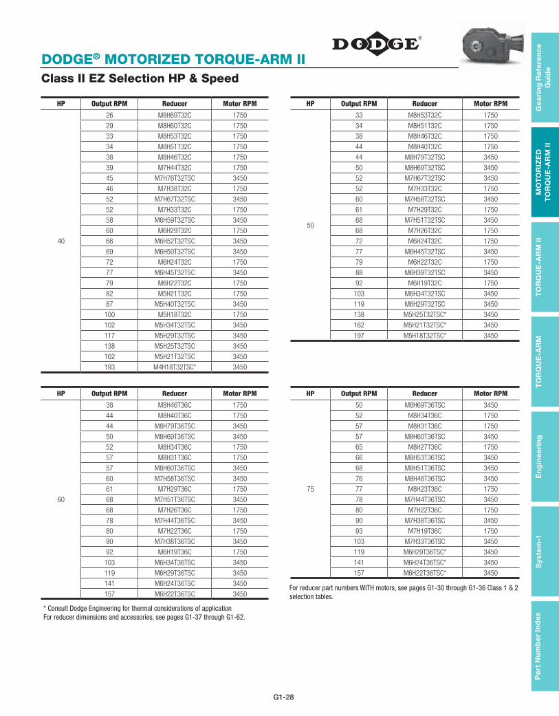
G1-28
DODGE® MOTORIZED TORQUE-ARM II
Pa
rt N
um
be
r In
dex
En
gin
ee
rin
gS
yste
m-1
TO
RQ
UE
-AR
M
TO
RQ
UE
-AR
M II
MO
TO
RIZ
ED
T
OR
QU
E-A
RM
IIG
eari
ng
Ref
ere
nc
e G
uid
e
Class II EZ Selection HP & Speed
HP Output RPM Reducer Motor RPM HP Output RPM Reducer Motor RPM
40
26 M8H69T32C 1750
50
33 M8H53T32C 1750
29 M8H60T32C 1750 34 M8H51T32C 1750
33 M8H53T32C 1750 38 M8H46T32C 1750
34 M8H51T32C 1750 44 M8H40T32C 1750
38 M8H46T32C 1750 44 M8H79T32TSC 3450
39 M7H44T32C 1750 50 M8H69T32TSC 3450
45 M7H76T32TSC 3450 52 M7H67T32TSC 3450
46 M7H38T32C 1750 52 M7H33T32C 1750
52 M7H67T32TSC 3450 60 M7H58T32TSC 3450
52 M7H33T32C 1750 61 M7H29T32C 1750
58 M6H59T32TSC 3450 68 M7H51T32TSC 3450
60 M6H29T32C 1750 68 M7H26T32C 1750
66 M6H52T32TSC 3450 72 M6H24T32C 1750
69 M6H50T32TSC 3450 77 M6H45T32TSC 3450
72 M6H24T32C 1750 79 M6H22T32C 1750
77 M6H45T32TSC 3450 88 M6H39T32TSC 3450
79 M6H22T32C 1750 92 M6H19T32C 1750
82 M5H21T32C 1750 103 M6H34T32TSC 3450
87 M5H40T32TSC 3450 119 M6H29T32TSC 3450
100 M5H18T32C 1750 138 M5H25T32TSC* 3450
102 M5H34T32TSC 3450 162 M5H21T32TSC* 3450
117 M5H29T32TSC 3450 197 M5H18T32TSC* 3450
138 M5H25T32TSC 3450
162 M5H21T32TSC 3450
193 M4H18T32TSC* 3450
HP Output RPM Reducer Motor RPM HP Output RPM Reducer Motor RPM
60
38 M8H46T36C 1750
75
50 M8H69T36TSC 3450
44 M8H40T36C 1750 52 M8H34T36C 1750
44 M8H79T36TSC 3450 57 M8H31T36C 1750
50 M8H69T36TSC 3450 57 M8H60T36TSC 3450
52 M8H34T36C 1750 65 M8H27T36C 1750
57 M8H31T36C 1750 66 M8H53T36TSC 3450
57 M8H60T36TSC 3450 68 M8H51T36TSC 3450
60 M7H58T36TSC 3450 76 M8H46T36TSC 3450
61 M7H29T36C 1750 77 M8H23T36C 1750
68 M7H51T36TSC 3450 78 M7H44T36TSC 3450
68 M7H26T36C 1750 80 M7H22T36C 1750
78 M7H44T36TSC 3450 90 M7H38T36TSC 3450
80 M7H22T36C 1750 93 M7H19T36C 1750
90 M7H38T36TSC 3450 103 M7H33T36TSC 3450
92 M6H19T36C 1750 119 M6H29T36TSC* 3450
103 M6H34T36TSC 3450 141 M6H24T36TSC* 3450
119 M6H29T36TSC 3450 157 M6H22T36TSC* 3450
141 M6H24T36TSC 3450
157 M6H22T36TSC 3450
* Consult Dodge Engineering for thermal considerations of applicationFor reducer dimensions and accessories, see pages G1-37 through G1-62.
For reducer part numbers WITH motors, see pages G1-30 through G1-36 Class 1 & 2 selection tables.

G1-29
DODGE® MOTORIZED TORQUE-ARM II
Gea
ring
Refe
ren
ce
Gu
ide
TO
RQ
UE
-AR
M II
MO
TO
RIZ
ED
T
OR
QU
E-A
RM
IIT
OR
QU
E-A
RM
E
ng
ine
erin
gS
ystem-1
Pa
rt Nu
mb
er In
dex
Class II EZ Selection HP & Speed
HP Output RPM Reducer Motor RPM
100
68 M8H51T405TSC* 3450
76 M8H46T405TSC* 3450
77 M8H23T405C* 1750
86 M8H40T405TSC* 3450
100 M8H17T405C* 1750
102 M8H34T405TSC* 3450
103 M7H33T405TSC* 3450
120 M7H29T405TSC* 3450
134 M7H26T405TSC* 3450
* Consult Dodge Engineering for thermal considerations of application
For reducer dimensions and accessories, see pages G1-37 through G1-62.
For reducer part numbers WITH motors, see pages G1-30 through G1-36 Class 1 & 2 selection tables.

G1-30
DODGE® MOTORIZED TORQUE-ARM II
Pa
rt N
um
be
r In
dex
En
gin
ee
rin
gS
yste
m-1
TO
RQ
UE
-AR
M
TO
RQ
UE
-AR
M II
MO
TO
RIZ
ED
T
OR
QU
E-A
RM
IIG
eari
ng
Ref
ere
nc
e G
uid
e
MTA EZ Selection TablesClass 1, 1.0 Service Factor
EZ Selection Tables
MTA EZ Selection TablesClass 2, 1.4 Service Factor
MTA2115H CLASS 1
Output RPM Ratio Class 1 Motor HP Motor speed Part Number C-Face GearMotor Part Number Service factor
23 76.96 3 1750 M2H77T18C M2H77T18C318 1.47 25 71.18 3 1750 M2H71T18C M2H71T18C318 1.60 26 66.07 5 1750 M2H66T18C M2H66T18C518 1.01 30 58.29 5 1750 M2H58T18C M2H58T18C518 1.16 34 51.31 5 1750 M2H51T18 M2H51T18C518 1.29 37 47.45 5 1750 M2H47T18C M2H47T18C518 1.40 40 44.05 7.5 1750 M2H44T21C M2H44T21C718 1.01 45 38.86 7.5 1750 M2H39T21C M2H39T21C718 1.12 49 35.88 7.5 1750 M2H36T21C M2H36T21C718 1.20 52 66.07 7.5 3450 M2H66T21C M2H66T21C736 1.27 54 32.15 7.5 1750 M2H32T21C M2H32T21C718 1.31 59 29.64 10 1750 M2H30T21C M2H30T21C1018 1.05 67 51.31 10 3450 M2H51T21C M2H51T21C1036 1.17 70 24.87 10 1750 M2H25T21C M2H25T21C1018 1.21 73 47.45 10 3450 M2H47T21C M2H47T21C1036 1.25 78 44.05 10 3450 M2H44T21C M2H44T21C1036 1.31 82 21.22 10 1750 M2H21T21C M2H21T21C1018 1.37 89 38.86 10 3450 M2H39T21C M2H39T21C1036 1.46 96 35.88 15 3450 M2H36T25C M2H36T25C1536 1.03 99 17.68 15 1750 M2H18T25C M2H18T25C1518 1.05
107 32.15 15 3450 M2H32T25C M2H32T25C1536 1.11 116 29.64 15 3450 M2H30T25C M2H30T25C1536 1.17 139 24.87 15 3450 M2H25T25C M2H25T25C1536 1.32 163 21.22 20* 3450 M2H21T25C M2H21T25C2036 1.12 195 17.68 20* 3450 M2H18T25C M2H18T25C2036 1.28
* Consult Dodge Engineering for thermal considerations of application
MTA2115H
MTA2115H CLASS 2
Output RPM Ratio Class 2 Mtr HP Motor speed Part Number C-Face GearMotor Part Number Service factor
23 76.96 3 1750 M2H77T18C M2H77T18C318 1.47 25 71.18 3 1750 M2H71T18C M2H71T18C318 1.60 26 66.07 3 1750 M2H66T18C M2H66T18C318 1.68 30 58.29 3 1750 M2H58T18C M2H58T18C318 1.94 34 51.31 3 1750 M2H51T18C M2H51T18C318 2.16 37 47.45 3 1750 M2H47T18C M2H47T18C318 2.33 40 44.05 5 1750 M2H44T18C M2H44T18C518 1.51 45 38.86 5 1750 M2H39T18C M2H39T18C518 1.68 49 35.88 5 1750 M2H36T18C M2H36T18C518 1.80 52 66.07 5 3450 M2H66T18C M2H66T18C536 1.90 54 32.15 5 1750 M2H32T18C M2H32T18C518 1.96 59 29.64 5 1750 M2H30T18C M2H30T18C518 2.11 67 51.31 7.5 3450 M2H51T21C M2H51T21C736 1.56 70 24.87 7.5 1750 M2H25T21C M2H25T21C718 1.62 73 47.45 7.5 3450 M2H47T21C M2H47T21C736 1.66 78 44.05 7.5 3450 M2H44T21C M2H44T21C736 1.74 82 21.22 7.5 1750 M2H21T21C M2H21T21C718 1.82 89 38.86 10 3450 M2H39T21C M2H39T21C1036 1.46 96 35.88 10 3450 M2H36T21C M2H36T21C1036 1.54 99 17.68 10 1750 M2H18T21C M2H18T21C1018 1.57
107 32.15 10 3450 M2H32T21C M2H32T21C1036 1.66 116 29.64 10 3450 M2H30T21C M2H30T21C1036 1.76 139 24.87 10 3450 M2H25T21C M2H25T21C1036 1.98 163 21.22 15 3450 M2H21T25C M2H21T25C1536 1.49 195 17.68 15 3450 M2H18T25C M2H18T25C1536 1.71
For reducer dimensions and accessories, see pages G1-37 through G1-40.

G1-31
DODGE® MOTORIZED TORQUE-ARM II
Gea
ring
Refe
ren
ce
Gu
ide
TO
RQ
UE
-AR
M II
MO
TO
RIZ
ED
T
OR
QU
E-A
RM
IIT
OR
QU
E-A
RM
E
ng
ine
erin
gS
ystem-1
Pa
rt Nu
mb
er In
dex
MTA3203H CLASS 1
Output RPM Ratio Class 1 Motor HP Motor speed Part Number C-Face GearMotor Part Number Service factor
23 76.02 5 1750 M3H76T18C M3H76T18C518 1.42 25 70.30 5 1750 M3H70T18C M3H70T18C518 1.48 27 65.26 7.5 1750 M3H65T21C M3H65T21C718 1.04 30 57.58 7.5 1750 M3H58T21C M3H58T21C718 1.20 35 50.68 10 1750 M3H51T21C M3H51T21C1018 1.01 37 46.87 10 1750 M3H47T21C M3H47T21C1018 1.09 40 43.51 10 1750 M3H44T21C M3H44T21C1018 1.19 46 38.39 10 1750 M3H38T21C M3H38T21C1018 1.31 49 35.44 10 1750 M3H35T21C M3H35T21C1018 1.42 53 65.26 10 3450 M3H65T21C M3H65T21C1036 1.48 55 31.75 15 1750 M3H32T25C M3H32T25C1518 1.02 60 29.28 15 1750 M3H29T25C M3H29T25C1518 1.09 68 50.68 15 3450 M3H51T25C M3H51T25C1536 1.18 71 24.57 15 1750 M3H25T25C M3H25T25C1518 1.26 74 46.87 15 3450 M3H47T25C M3H47T25C1536 1.30 79 43.51 20 3450 M3H44T25C M3H44T25C2036 1.04 83 20.96 20 1750 M3H21T25C M3H21T25C2018 1.08 90 38.39 20 3450 M3H38T25C M3H38T25C2036 1.15 97 35.44 20 3450 M3H35T25C M3H35T25C2036 1.23
100 17.46 20 1750 M3H17T25C M3H17T25C2018 1.26 109 31.75 20 3450 M3H32T25C M3H32T25C2036 1.34 118 29.28 25 3450 M3H29T28TSC M3H29T28TSC2536 1.15 140 24.57 30 3450 M3H25T28TSC M3H25T28TSC3036 1.09 165 20.96 30 3450 M3H21T28TSC M3H21T28TSC3036 1.22 198 17.46 30 3450 M3H17T28TSC M3H17T28TSC3036 1.37
* Consult Dodge Engineering for thermal considerations of application
MTA3203H
MTA3203H CLASS 2
Output RPM Ratio Class 2 Motor HP Motor speed Part Number C-Face GearMotor Part Number Service factor
23 76.02 5 1750 M3H76T18C M3H76T18C518 1.42 25 70.30 5 1750 M3H70T18C M3H70T18C518 1.48 27 65.26 5 1750 M3H65T18C M3H65T18C518 1.56 30 57.58 5 1750 M3H58T18C M3H58T18C518 1.80 35 50.68 5 1750 M3H51T18C M3H51T18C518 2.03 37 46.87 7.5 1750 M3H47T21C M3H47T21C718 1.46 40 43.51 7.5 1750 M3H44T21C M3H44T21C718 1.58 46 38.39 7.5 1750 M3H38T21C M3H38T21C718 1.74 49 35.44 10 1750 M3H35T21C M3H35T21C1018 1.42 53 65.26 10 3450 M3H65T21C M3H65T21C1036 1.48 55 31.75 10 1750 M3H32T21C M3H32T21C1018 1.53 60 29.28 10 1750 M3H29T21C M3H29T21C1018 1.64 68 50.68 10 3450 M3H51T21C M3H51T21C1036 1.77 71 24.57 10 1750 M3H25T21C M3H25T21C1018 1.89 74 46.87 10 3450 M3H47T21C M3H47T21C1036 1.95 79 43.51 15 3450 M3H44T25C M3H44T25C1536 1.38 83 20.96 15 1750 M3H21T25C M3H21T25C1518 1.44 90 38.39 15 3450 M3H38T25C M3H38T25C1536 1.54 97 35.44 15 3450 M3H35T25C M3H35T25C1536 1.64
100 17.46 15 1750 M3H17T25C M3H17T25C1518 1.68 109 31.75 15 3450 M3H32T25C M3H32T25C1536 1.79 118 29.28 20 3450 M3H29T25C M3H29T25C2036 1.44 140 24.57 20 3450 M3H25T25C M3H25T25C2036 1.64 165 20.96 25 3450 M3H21T28TSC M3H21T28TSC2536 1.47 198 17.46 25 3450 M3H17T28TSC M3H17T28TSC2536 1.64
MTA EZ Selection TablesClass 1, 1.0 Service Factor
MTA EZ Selection TablesClass 2, 1.4 Service Factor
For reducer dimensions and accessories, see pages G1-41 through G1-44.

G1-32
DODGE® MOTORIZED TORQUE-ARM II
Pa
rt N
um
be
r In
dex
En
gin
ee
rin
gS
yste
m-1
TO
RQ
UE
-AR
M
TO
RQ
UE
-AR
M II
MO
TO
RIZ
ED
T
OR
QU
E-A
RM
IIG
eari
ng
Ref
ere
nc
e G
uid
e
MTA EZ Selection TablesClass 1, 1.0 Service Factor
MTA EZ Selection TablesClass 2, 1.4 Service Factor
MTA4207H CLASS 1
Output RPM Ratio Class 1 Motor HP Motor speed Part Number C-Face GearMotor Part Number Service factor
24 73.57 10 1750 M4H74T21C M4H74T21C1018 1.15 26 66.17 10 1750 M4H66T21C M4H66T21C1018 1.24 29 61.04 10 1750 M4H61T21C M4H61T21C1018 1.32 34 51.72 15 1750 M4H52T25C M4H52T25C1518 1.04 36 49.04 15 1750 M4H49T25C M4H49T25C1518 1.09 40 44.11 15 1750 M4H44T25C M4H44T25C1518 1.20 43 40.70 15 1750 M4H41T25C M4H41T25C1518 1.27 47 73.57 20 3450 M4H74T25C M4H74T25C2036 1.01 51 34.48 20 1750 M4H34T25C M4H34T25C2018 1.09 52 66.17 20 3450 M4H66T25C M4H66T25C2036 1.13 57 61.04 20 3450 M4H61T25C M4H61T25C2036 1.20 58 30.05 20 1750 M4H30T25C M4H30T25C2018 1.24 67 51.72 25 3450 M4H52T28TSC M4H52T28TSC2536 1.10 68 25.57 25 1750 M4H26T28C M4H26T28C2518 1.13 70 49.04 25 3450 M4H49T28TSC M4H49T28TSC2536 1.16 78 44.11 30 3450 M4H44T28TSC M4H44T28TSC3036 1.06 80 21.82 30 1750 M4H22T28C M4H22T28C3018 1.08 85 40.70 30 3450 M4H41T28TSC M4H41T28TSC3036 1.13 98 17.89 30 1750 M4H18T28C M4H18T28C2518 1.29
100 34.48 30 3450 M4H34T28TSC M4H34T32TSC3036 1.31 115 30.05 40* 3450 M4H30T32TSC M4H30T32TSC4036 1.07 135 25.57 40* 3450 M4H26T32TSC M4H26T32TSC4036 1.18 158 21.82 50* 3450 M4H22T32TSC M4H22T32TSC5036 1.06 193 17.89 50* 3450 M4H18T32TSC M4H18T32TSC5036 1.19
* Consult Dodge Engineering for thermal considerations of application
MTA4207H
MTA4207H CLASS 2
Output RPM Ratio Class 2 Motor HP Motor speed Part Number C-Face GearMotor Part Number Service factor
24 73.57 7.5 1750 M4H74T21C M4H74T21C718 1.53 26 66.17 7.5 1750 M4H66T21C M4H66T21C718 1.65 29 61.04 7.5 1750 M4H61T21C M4H61T21C718 1.76 34 51.72 10 1750 M4H52T21C M4H52T21C1018 1.56 36 49.04 10 1750 M4H49T21C M4H49T21C1018 1.64 40 44.11 10 1750 M4H44T21C M4H44T21C1018 1.80 43 40.70 10 1750 M4H41T21C M4H41T21C1018 1.90 47 73.57 10 3450 M4H74T21C M4H74T21C1036 2.03 51 34.48 15 1750 M4H34T25C M4H34T25C1518 1.45 52 66.17 15 3450 M4H66T25C M4H66T25C1536 1.50 57 61.04 15 3450 M4H61T25C M4H61T25C1536 1.60 58 30.05 15 1750 M4H30T25C M4H30T25C1518 1.65 67 51.72 15 3450 M4H52T25C M4H52T25C1536 1.84 68 25.57 20 1750 M4H26T25C M4H26T25C2018 1.42 70 49.04 20 3450 M4H49T25C M4H49T25C2036 1.45 78 44.11 20 3450 M4H44T25C M4H44T25C2036 1.59 80 21.82 20 1750 M4H22T25C M4H22T25C2018 1.63 85 40.70 20 3450 M4H41T25C M4H41T25C2036 1.69 98 17.89 25 1750 M4H18T28C M4H18T28C2518 1.54
100 34.48 25 3450 M4H34T28TSC M4H34T28TSC2536 1.57 115 30.05 30 3450 M4H30T28TSC M4H30T28TSC3036 1.43 135 25.57 30 3450 M4H26T28TSC M4H26T28TSC3036 1.58 158 21.82 30 3450 M4H22T28TSC M4H22T28TSC3036 1.76 193 17.89 40* 3450 M4H18T32TSC M4H18T32TSC4036 1.48
* Consult Dodge Engineering for thermal considerations of applicationFor reducer dimensions and accessories, see pages G1-45 through G1-48.

G1-33
DODGE® MOTORIZED TORQUE-ARM II
Gea
ring
Refe
ren
ce
Gu
ide
TO
RQ
UE
-AR
M II
MO
TO
RIZ
ED
T
OR
QU
E-A
RM
IIT
OR
QU
E-A
RM
E
ng
ine
erin
gS
ystem-1
Pa
rt Nu
mb
er In
dex
MTA EZ Selection TablesClass 1, 1.0 Service Factor
MTA EZ Selection TablesClass 2, 1.4 Service Factor
MTA5215H CLASS 1
Output RPM Ratio Class 1 Motor HP Motor speed Part Number C-Face GearMotor Part Number Service factor
24 71.98 15 1750 M5H72T25C M5H72T25C1518 1.28 27 64.74 20 1750 M5H65T25C M5H65T25C2018 1.04 29 59.73 20 1750 M5H60T25C M5H60T25C2018 1.15 35 50.61 25 1750 M5H51T28C M5H51T28C2518 1.07 36 47.99 25 1750 M5H48T28C M5H48T28C2518 1.13 41 43.16 30 1750 M5H43T28C M5H43T28C3018 1.04 44 39.82 30 1750 M5H40T28C M5H40T28C3018 1.10 48 71.98 30 3450 M5H72T28TSC M5H72T28TSC3036 1.19 52 33.74 30 1750 M5H34T28C M5H34T28C3018 1.29 53 64.74 30 3450 M5H65T28TSC M5H65T28TSC3036 1.32 58 59.73 40 3450 M5H60T32TSC M5H60T32TSC4036 1.07 60 29.41 40 1750 M5H29T32C M5H29T32C4018 1.09 68 50.61 40 3450 M5H51T32TSC M5H51T32TSC4036 1.24 70 25.05 50 1750 M5H25T32C M5H25T32C5018 1.01 72 47.99 50* 3450 M5H48T32TSC M5H48T32TSC5036 1.04 80 43.16 50* 3450 M5H43T32TSC M5H43T32TSC5036 1.14 82 21.35 50 1750 M5H21T32C M5H21T32C5018 1.17 87 39.82 50* 3450 M5H40T32TSC M5H40T32TSC5036 1.20
100 17.50 60 1750 M5H18T36C M5H18T36C6018 1.08 102 33.74 60* 3450 M5H34T36TSC M5H34T36TSC6036 1.10 117 29.41 60* 3450 M5H29T36TSC M5H29T36TSC6036 1.18 138 25.05 75* 3450 M5H25T36TSC M5H25T36TSC7536 1.03 162 21.35 75* 3450 M5H21T36TSC M5H21T36TSC7536 1.08 197 17.50 75* 3450 M5H18T36TSC M5H18T36TSC7536 1.14
* Consult Dodge Engineering for thermal considerations of application
MTA5215H
MTA5215H CLASS 2
Output RPM Ratio Class 2 Motor HP Motor speed Part Number C-Face GearMotor Part Number Service factor
24 71.98 10 1750 M5H72T21C M5H72T21C1018 1.92 27 64.74 10 1750 M5H65T21C M5H65T21C1018 2.08 29 59.73 15 1750 M5H60T25C M5H60T25C1518 1.53 35 50.61 15 1750 M5H51T25C M5H51T25C1518 1.78 36 47.99 15 1750 M5H48T25C M5H48T25C1518 1.88 41 43.16 20 1750 M5H43T25C M5H43T25C2018 1.55 44 39.82 20 1750 M5H40T25C M5H40T25C2018 1.65 48 71.98 25 3450 M5H72T28TSC M5H72T28TSC2536 1.43 52 33.74 25 1750 M5H34T28C M5H34T28C2518 1.55 53 64.74 25 3450 M5H65T28TSC M5H65T28TSC2536 1.58 58 59.73 30 3450 M5H60T28TSC M5H60T28TSC3036 1.43 60 29.41 30 1750 M5H29T28C M5H29T28C3018 1.45 68 50.61 30 3450 M5H51T28TSC M5H51T28TSC3036 1.66 70 25.05 30 1750 M5H25T28C M5H25T28C3018 1.68 72 47.99 30 3450 M5H48T28TSC M5H48T28TSC3036 1.73 80 43.16 30 3450 M5H43T28TSC M5H43T28TSC3036 1.90 82 21.35 40 1750 M5H21T32C M5H21T32C4018 1.46 87 39.82 40 3450 M5H40T32TSC M5H40T32TSC4036 1.50
100 17.50 40 1750 M5H18T32C M5H18T32C4018 1.62 102 33.74 40 3450 M5H34T32TSC M5H34T32TSC4036 1.64 117 29.41 40 3450 M5H29T32TSC M5H29T32TSC4036 1.77 138 25.05 50* 3450 M5H25T32TSC M5H25T32TSC5036 1.55 162 21.35 50* 3450 M5H21T32TSC M5H21T32TSC5036 1.62 197 17.50 50* 3450 M5H18T32TSC M5H18T32TSC5036 1.71
* Consult Dodge Engineering for thermal considerations of applicationFor reducer dimensions and accessories, see pages G1-49 through G1-52.

G1-34
DODGE® MOTORIZED TORQUE-ARM II
Pa
rt N
um
be
r In
dex
En
gin
ee
rin
gS
yste
m-1
TO
RQ
UE
-AR
M
TO
RQ
UE
-AR
M II
MO
TO
RIZ
ED
T
OR
QU
E-A
RM
IIG
eari
ng
Ref
ere
nc
e G
uid
e
MTA EZ Selection TablesClass 1, 1.0 Service Factor
MTA EZ Selection TablesClass 2, 1.4 Service Factor
MTA6307H CLASS 1
Output RPM Ratio Class 1 Motor HP Motor speed Part Number C-Face GearMotor Part Number Service factor
22 78.53 20 1750 M6H79T25C M6H79T25C2018 1.18 26 66.92 25 1750 M6H67T28C M6H67T28C2518 1.10 30 59.05 30 1750 M6H59T28C M6H59T28C3018 1.05 33 52.35 30 1750 M6H52T28C M6H52T28C3018 1.14 35 50.26 30 1750 M6H50T28C M6H50T28C3018 1.21 39 44.61 30 1750 M6H45T28C M6H45T28C3018 1.33 44 78.53 40 3450 M6H79T32TSC M6H79T32TSC4036 1.12 44 39.37 40 1750 M6H39T32C M6H39T32C4018 1.12 52 66.92 50 3450 M6H67T32TSC M6H67T32TSC5036 1.04 52 33.51 50 1750 M6H34T32C M6H34T32C5018 1.04 58 59.05 50 3450 M6H59T32TSC M6H59T32TSC5036 1.15 60 29.03 50 1750 M6H29T32C M6H29T32C5018 1.19 66 52.35 60 3450 M6H52T36TSC M6H52T36TSC6036 1.08 69 50.26 60 3450 M6H50T36TSC M6H50T36TSC6036 1.12 72 24.43 60 1750 M6H24T36C M6H24T36C6018 1.16 77 44.61 60 3450 M6H45T36TSC M6H45T36TSC6036 1.24 79 22.04 60 1750 M6H22T36C M6H22T36C6018 1.27 88 39.37 75* 3450 M6H39T36TSC M6H39T36TSC7536 1.11 92 18.95 75* 1750 M6H19T36C M6H19T36C7518 1.15
103 33.51 75* 3450 M6H34T36TSC M6H34T36TSC7536 1.26 119 29.03 75* 3450 M6H29T36TSC M6H29T36TSC7536 1.41 141 24.43 75* 3450 M6H24T36TSC M6H24T36TSC7536 1.60 157 22.04 75* 3450 M6H22T36TSC M6H22T36TSC7536 1.72
* Consult Dodge Engineering for thermal considerations of application
MTA6307H
MTA6307H CLASS 2
Output RPM Ratio Class 2 Motor HP Motor speed Part Number C-Face GearMotor Part Number Service factor
22 78.53 15 1750 M6H79T25C M6H79T25C1518 1.57 26 66.92 15 1750 M6H67T25C M6H67T25C1518 1.84 30 59.05 20 1750 M6H59T25C M6H59T25C2018 1.57 33 52.35 20 1750 M6H52T25C M6H52T25C2018 1.72 35 50.26 25 1750 M6H50T28C M6H50T28C2518 1.45 39 44.61 25 1750 M6H45T28C M6H45T28C2518 1.59 44 78.53 30 3450 M6H79T28TSC M6H79T28TSC3036 1.49 44 39.37 30 1750 M6H39T28C M6H39T28C3018 1.49 52 66.92 30 3450 M6H67T28TSC M6H67T28TSC3036 1.74 52 33.51 30 1750 M6H34T28C M6H34T28C3018 1.74 58 59.05 40 3450 M6H59T32TSC M6H59T32TSC4036 1.44 60 29.03 40 1750 M6H29T32C M6H29T32C4018 1.48 66 52.35 40 3450 M6H52T32TSC M6H52T32TSC4036 1.62 69 50.26 40 3450 M6H50T32TSC M6H50T32TSC4036 1.68 72 24.43 50 1750 M6H24T32C M6H24T32C5018 1.40 77 44.61 50 3450 M6H45T32TSC M6H45T32TSC5036 1.49 79 22.04 50 1750 M6H22T32C M6H22T32C5018 1.52 88 39.37 50 3450 M6H39T32TSC M6H39T32TSC5036 1.66 92 18.95 60 1750 M6H19T36C M6H19T36C6018 1.43
103 33.51 60 3450 M6H34T36TSC M6H34T36TSC6036 1.57 119 29.03 75* 3450 M6H29T36TSC M6H29T36TSC7536 1.41 141 24.43 75* 3450 M6H24T36TSC M6H24T36TSC7536 1.60 157 22.04 75* 3450 M6H22T36TSC M6H22T36TSC7536 1.72
* Consult Dodge Engineering for thermal considerations of applicationFor reducer dimensions and accessories, see pages G1-53 through G1-56.

G1-35
DODGE® MOTORIZED TORQUE-ARM II
Gea
ring
Refe
ren
ce
Gu
ide
TO
RQ
UE
-AR
M II
MO
TO
RIZ
ED
T
OR
QU
E-A
RM
IIT
OR
QU
E-A
RM
E
ng
ine
erin
gS
ystem-1
Pa
rt Nu
mb
er In
dex
MTA EZ Selection TablesClass 1, 1.0 Service Factor
MTA EZ Selection TablesClass 2, 1.4 Service Factor
MTA7315H CLASS 1
Output RPM Ratio Class 1 Motor HP Motor speed Part Number C-Face GearMotor Part Number Service factor
23 76.46 30 1750 M7H76T28C M7H76T28C3018 1.22 26 66.57 40 1750 M7H67T32C M7H67T32C4018 1.04 30 57.58 40 1750 M7H58T32C M7H58T32C4018 1.18 34 50.97 50 1750 M7H51T32C M7H51T32C5018 1.08 39 44.38 60 1750 M7H44T36C M7H44T36C6018 1.02 45 76.46 60 3450 M7H76T36TSC M7H76T36TSC6036 1.16 46 38.39 60 1750 M7H38T36C M7H38T36C6018 1.15 52 66.57 75 3450 M7H67T36TSC M7H67T36TSC7536 1.04 52 33.48 75 1750 M7H33T36C M7H33T36C7518 1.04 60 57.58 75 3450 M7H58T36TSC M7H58T36TSC7536 1.18 61 28.65 75 1750 M7H29T36C M7H29T36C7518 1.20 68 50.97 75 3450 M7H51T36TSC M7H51T36TSC7536 1.32 68 25.66 75 1750 M7H26T36C M7H26T36C7518 1.32 78 44.38 100* 3450 M7H44T405TSC – 1.12 80 21.74 100 1750 M7H22T405C M7H22T405C10018 1.15 90 38.39 100* 3450 M7H38T405TSC – 1.28 93 18.77 100 1750 M7H19T405C M7H19T405C10018 1.29
103 33.48 100* 3450 M7H33T405TSC – 1.42 120 28.65 100* 3450 M7H29T405TSC – 1.62 134 25.66 100* 3450 M7H26T405TSC – 1.77
* Consult Dodge Engineering for thermal considerations of application
MTA7315H
MTA7315H CLASS 2
Output RPM Ratio Class 2 Motor HP Motor speed Part Number C-Face GearMotor Part Number Service factor
23 76.46 25 1750 M7H76T28C M7H76T28C2518 1.47 26 66.57 25 1750 M7H67T28C M7H67T28C2518 1.67 30 57.58 30 1750 M7H58T28C M7H58T28C3018 1.58 34 50.97 30 1750 M7H51T28C M7H51T28C3018 1.79 39 44.38 40 1750 M7H44T32C M7H44T32C4018 1.52 45 76.46 40 3450 M7H76T32TSC M7H76T32TSC4036 1.74 46 38.39 40 1750 M7H38T32C M7H38T32C4018 1.73 52 66.57 50 3450 M7H67T32TSC M7H67T32TSC5036 1.56 52 33.48 50 1750 M7H33T32C M7H33T32C5018 1.56 60 57.58 60 3450 M7H58T36TSC M7H58T36TSC6036 1.48 61 28.65 60 1750 M7H29T36C M7H29T36C6018 1.50 68 50.97 60 3450 M7H51T36TSC M7H51T36TSC6036 1.64 68 25.66 60 1750 M7H26T36C M7H26T36C6018 1.65 78 44.38 75 3450 M7H44T36TSC M7H44T36TSC7536 1.49 80 21.74 75 1750 M7H22T36C M7H22T36C7518 1.53 90 38.39 75 3450 M7H38T36TSC M7H38T36TSC7536 1.70 93 18.77 75 1750 M7H19T36C M7H19T36C7518 1.73
103 33.48 100* 3450 M7H33T405TSC – 1.42 120 28.65 100* 3450 M7H29T405TSC – 1.62 134 25.66 100* 3450 M7H26T405TSC – 1.77
* Consult Dodge Engineering for thermal considerations of applicationFor reducer dimensions and accessories, see pages G1-57 through G1-60.

G1-36
DODGE® MOTORIZED TORQUE-ARM II
Pa
rt N
um
be
r In
dex
En
gin
ee
rin
gS
yste
m-1
TO
RQ
UE
-AR
M
TO
RQ
UE
-AR
M II
MO
TO
RIZ
ED
T
OR
QU
E-A
RM
IIG
eari
ng
Ref
ere
nc
e G
uid
e
MTA EZ Selection TablesClass 1, 1.0 Service Factor
MTA EZ Selection TablesClass 2, 1.4 Service Factor
MTA8407H CLASS 1
Output RPM Ratio Class 1 Motor HP Motor speed Part Number C-Face GearMotor Part Number Service factor
22 78.80 50 1750 M8H79T32C M8H79T32C5018 1.02 26 68.53 50 1750 M8H69T32C M8H69T32C5018 1.16 29 60.13 60 1750 M8H60T36C M8H60T36C6018 1.08 33 52.53 60 1750 M8H53T36C M8H53T36C6018 1.24 34 50.85 75 1750 M8H51T36C M8H51T36C7518 1.01 38 45.69 75 1750 M8H46T36C M8H46T36C7518 1.12 44 40.09 75 1750 M8H40T36C M8H40T36C7518 1.28 44 78.80 75 3450 M8H79T36TSC M8H79T36TSC7536 1.26 50 68.53 100* 3450 M8H69T405TSC – 1.08 52 33.90 100 1750 M8H34T405C M8H34T405C10018 1.10 57 30.76 100 1750 M8H31T405C M8H31T405C10018 1.20 57 60.13 100* 3450 M8H60T405TSC – 1.21 65 26.82 100 1750 M8H27T405C M8H27T405C10018 1.36 66 52.53 100* 3450 M8H53T405TSC – 1.36 68 50.85 100* 3450 M8H51T405TSC – 1.41 76 45.69 100* 3450 M8H46T405TSC – 1.55 77 22.77 100 1750 M8H23T405C M8H23T405C10018 1.56 86 40.09 100* 3450 M8H40T405TSC – 1.74 100 17.43 100 1750 M8H17T405C – 2.02 102 33.90 100* 3450 M8H34T405TSC – 2.04 112 30.76 100* 3450 M8H31T405TSC – 2.21
* Consult Dodge Engineering for thermal considerations of application
MTA8407H
MTA8407H CLASS 2
Output RPM Ratio Class 2 Motor HP Motor speed Part Number C-Face GearMotor Part Number Service factor
22 78.80 30 1750 M8H79T28C M8H79T28C3018 1.69 26 68.53 40 1750 M8H69T32C M8H69T32C4018 1.45 29 60.13 40 1750 M8H60T32C M8H60T32C4018 1.62 33 52.53 50 1750 M8H53T32C M8H53T32C5018 1.49 34 50.85 50 1750 M8H51T32C M8H51T32C5018 1.52 38 45.69 60 1750 M8H46T36C M8H46T36C6018 1.40 44 40.09 60 1750 M8H40T36C M8H40T36C6018 1.60 44 78.80 60 3450 M8H79T36TSC M8H79T36TSC6036 1.57 50 68.53 75 3450 M8H69T36TSC M8H69T36TSC7536 1.45 52 33.90 75 1750 M8H34T36C M8H34T36C7518 1.47 57 30.76 75 1750 M8H31T36C M8H31T36C7518 1.60 57 60.13 75 3450 M8H60T36TSC M8H60T36TSC7536 1.61 65 26.82 75 1750 M8H27T36C M8H27T36C7518 1.81 66 52.53 75 3450 M8H53T36TSC M8H53T36TSC7536 1.81 68 50.85 100* 3450 M8H51T405TSC – 1.41 76 45.69 100* 3450 M8H46T405TSC – 1.55 77 22.77 100 1750 M8H23T405C M8H23T405C10018 1.56 86 40.09 100* 3450 M8H40T405TSC – 1.74
100 17.43 100 1750 M8H17T405C M8H17T405C10018 2.02 102 33.90 100* 3450 M8H34T405TSC – 2.04 112 30.76 100* 3450 M8H31T405TSC – 2.21
* Consult Dodge Engineering for thermal considerations of applicationFor reducer dimensions and accessories, see pages G1-61 through G1-62.

G1-37
DODGE® MOTORIZED TORQUE-ARM II
Gea
ring
Refe
ren
ce
Gu
ide
TO
RQ
UE
-AR
M II
MO
TO
RIZ
ED
T
OR
QU
E-A
RM
IIT
OR
QU
E-A
RM
E
ng
ine
erin
gS
ystem-1
Pa
rt Nu
mb
er In
dex
MTA2115 Shaft Mounted Reducer
Shaft Mounted Reducer and Accessories MTA2115
Reducer with Backstop
2.07
6.75
13.48
5.06
6.646.928.07
3.90
1.06
3.00
7/16 BOLTS
19.30
3.757
3.757
Ø3.92
4.05
END OF BEARINGON DRIVEN SHAFT
B
A
4.38
4.03
2-3/16" MAX
2.58
3.69
5.32
7.55
1.25
1.20
6.690 - 210 NEMA MOTOR FRAME7.310 - 250 NEMA MOTOR FRAME
9.000 - 180/210/250 NEMA MOTOR FRAME
A = 5.070 - 140 NEMA MOTOR FRAME6.030 - 180 NEMA MOTOR FRAME
B = 6.500 - 140 NEMA MOTOR FRAME
MTA2115 Shaft Mounted Drive
REDUCER WITH BACKSTOP
TIE ROD SHOULD BE MOUNTED AT A 90° ANGLE IN RELATION TO THE CENTER OF THE DRIVEN SHAFT
4 HOLES @ 90° 7/16-14NC X 0.75 DEEP
90°
27.00 MIN33.0 MAX

G1-38
DODGE® MOTORIZED TORQUE-ARM II
Pa
rt N
um
be
r In
dex
En
gin
ee
rin
gS
yste
m-1
TO
RQ
UE
-AR
M
TO
RQ
UE
-AR
M II
MO
TO
RIZ
ED
T
OR
QU
E-A
RM
IIG
eari
ng
Ref
ere
nc
e G
uid
e
MTA2115 Shaft Mounted Accessories
MTA2115H AccessoriesDescription Part Number Weight lbs.
TA2115RA Rod Assembly 902109 6.9
TA3203BS Backstop Assembly use for MTA2115 903102 4.7
TA0-TA3 Vertical Breather Kit 900112 2.0
V-ring Seal Kit 902249 0.1
TA0-TA3 Hydra-Lock Dessicant Breather Kit 964372 0.2
MTA2-8 Vertical Position D Breather Kit 472300 3.0
Bushing & Safety End Covers
Reducer SizeMetal End Cover Part Numbers
Closed Weight Split WeightMTA2115H 902114 0.6 902115 0.5
Reducer SizeABS End Cover Part Numbers
Closed Weight Split WeightMTA2115H 902142 0.6 902143 0.5
MTA is drilled and tapped to accept the ABS bushing cover bolts. Aluminum covers require customer fitment to the reducer. Bushing covers fit both the outboard and inboard side of the MTA reducer.
TA2115H Tapered Bushing Kits (5) (6) TA2115H Short shaft Tapered Bushing KitsBushing Size
Standard Shaft (7)Bushing Kit
Part Number
Weight lbs.
Shaft Keyseat Required (9) (10)
Bushing Size Short Shaft Bushing Kit
Part Number
(8)
Weight lbs.
Shaft Keyseat Required (9)(10)
TA2115TB x 2-3/16 902020 4.7 1/2 x 1/4 x 7.80 – – – –
TA2115TB x 2 902022 5.2 1/2 x 1/4 x 7.80 – – – –
TA2115TB x 1-15/16 ▲ 902023 5.4 1/2 x 1/4 x 7.80 TA2115TBS x 1-15/16 902030 5.6 1/2 x 1/4 x 4.80
TA2115TB x 1-7/8 902024 5.6 1/2 x 1/4 x 7.80 TA2115TBS x 1-7/8 902031 5.9 1/2 x 1/4 x 4.80
TA2115TB x 1-3/4 902025 5.8 3/8 x 3/16 x 7.80 TA2115TBS x 1-3/4 902032 6 3/8 x 3/16 x 4.80
TA2115TB x 1-11/16 902026 6.1 3/8 x 3/16 x 7.80 TA2115TBS x 1-11/16 902033 6.6 3/8 x 3/16 x 4.80
TA2115TB x 1-5/8 902027 6.0 3/8 x 3/16 x 7.80 TA2115TBS x 1-5/8 902034 6.8 3/8 x 3/16 x 4.80
TA2115TB x 1-1/2 902028 6.4 3/8 x 3/16 x 7.80 TA2115TBS x 1-1/2 902035 7.3 3/8 x 3/16 x 4.80
TA2115TB x 1-7/16 902029 6.4 3/8 x 3/16 x 7.80 TA2115TBS x 1-7/16 902036 7.4 3/8 x 3/16 x 4.80
TA2115TB x 1-3/8 902060 6.5 5/16 x 5/32 x 7.80 TA2115TBS x 1-3/8 902037 7.6 5/16 x 5/32 x 4.80
TA2115TB x 1-5/16 902061 6.7 5/16 x 5/32 x 7.80 TA2115TBS x 1-5/16 902038 7.8 5/16 x 5/32 x 4.80
▲ AGMA maximum bore size(5) Bushing kit required to mount TA II reducer to driven shaft(6) Bushing kit is not required to mount TA II reducer on SCS Drive Shaft in a screw conveyor application(7) Standard Shaft Bushing Kit includes two standard bushings with back-up plates and snap rings; hardware, and key
(8)Short Shaft Bushing Kit includes one standard bushing, one long bushing with insertable wedge; two back-up plates with snap rings; hardware and key. This is an optional bushing for after market, short shaft mounting.
(9) Minimum keyseat and shaft length required to mount reducer with bushing kit(10) Always check the driven shaft and key for strength
MTA2115 C-Face Reducer Weights with adapter (lbs)
Adapter size
Reducer 180 210 250 280 280TSC 320 360 320TSC & 360TSC
Weight (lbs) 155 160 165 – – – – –

G1-39
DODGE® MOTORIZED TORQUE-ARM II
Gea
ring
Refe
ren
ce
Gu
ide
TO
RQ
UE
-AR
M II
MO
TO
RIZ
ED
T
OR
QU
E-A
RM
IIT
OR
QU
E-A
RM
E
ng
ine
erin
gS
ystem-1
Pa
rt Nu
mb
er In
dex
MTA2115 Screw Conveyor Reducer
MTA2115H Screw Conveyor Drive Dimensions
Dimensions
Screw Dia Drive Shaft Dia A B C D Hole Dia E F G Bolt Dia H
6, 9 1-1/2 9.00 2.13 3.00 17/32 0.75 4.00 1/2-13
9, 12 2 9.00 2.13 3.00 21/32 0.75 5.13 5/8
12, 14 2-7/16 9.69 2.75 3.00 21/32 0.75 5.63 5/8
12, 14, 16, 3 9.88 2.88 3.00 25/32 0.75 6.00 3/4
18, 20 – – – – – – – –

G1-40
DODGE® MOTORIZED TORQUE-ARM II
Pa
rt N
um
be
r In
dex
En
gin
ee
rin
gS
yste
m-1
TO
RQ
UE
-AR
M
TO
RQ
UE
-AR
M II
MO
TO
RIZ
ED
T
OR
QU
E-A
RM
IIG
eari
ng
Ref
ere
nc
e G
uid
e
MTA2115 Screw Conveyor Accessories
Bushing & Safety End Covers
Reducer SizeMetal End Cover Part Numbers
Closed Weight Split Weight
MTA2115H 902114 0.6 902115 0.5
Reducer SizeABS End Cover Part Numbers
Closed Weight Split Weight
MTA2115H 902142 0.6 902143 0.5
MTA is drilled and tapped to accept the ABS bushing cover bolts. Aluminum covers require customer fitment to the reducer. Bushing covers fit both the outboard and inboard side of the MTA reducer.
MTA2115H Accessories for Screw Conveyor Drives (4) (5)
Description Part Number Weight lbs.
TA2115SCA Adapter & Hardware Kit (2) 902070 19.2
TA2115SCP Adjustable Packing Kit (3) 902071 1.2
TA2115SCS x 1-1/2 Drive Shaft 902072 15.4
TA2115SCS x 2 Drive Shaft 902073 18.6
TA2115SCS x 2-7/16 Drive Shaft 902074 23.3
TA2115SCS x 3 Drive Shaft 902075 29.5
TA2115SCS x 1-1/2 Stainless Steel Drive Shaft 902080 15.4
TA2115SCS x 2 Stainless Steel Drive Shaft 902081 18.6
TA2115SCS x 2-7/16 Stainless Steel Drive Shaft 902082 23.3
TA2115SCS x 3 Stainless Steel Drive Shaft 902083 29.5
(2) SCA Adapter & Hardware Kit includes adapter, mounting wedge, keeper plate, key, seals and hardware(3) SCP Adjustable Packing Kit consists of flange, mounting hardware and braided packing seals(4) SCS Drive Shaft is a shaft only. Hardware is stocked with the adapter & hardware kit(5) A complete TA II Screw Conveyor Drive includes a TA II Reducer, SCA Adapter & Hardware Kit and SCS Drive Shaft. The SCP Adjustable Packing Kit is an optional accessory.

G1-41
DODGE® MOTORIZED TORQUE-ARM II
Gea
ring
Refe
ren
ce
Gu
ide
TO
RQ
UE
-AR
M II
MO
TO
RIZ
ED
T
OR
QU
E-A
RM
IIT
OR
QU
E-A
RM
E
ng
ine
erin
gS
ystem-1
Pa
rt Nu
mb
er In
dex
MTA3203 Shaft Mounted Reducer
MTA3203
Reducer with Backstop
3.00
21.43
27.00 MIN33.00 MAX
7.87
9.20
5.57
7.4114.82
7/16 BOLT
1.20
1.25
B
A
4.88 2-3/8" MAX
4.74
2.805.92
4.13
8.62
END OF BEARINGON DRIVEN SHAFT
4.51
4.51
( 4) HOLES @ 901/2-13 X 1.00 DEEP
4.12
4.98
2.28
A = 6.030 - 180 NEMA MOTOR FRAME6.690 - 210 NEMA MOTOR FRAME7.310 - 250 NEMA MOTOR FRAME6.425 - 280TSC NEMA MOTOR FRAME
B = 9.000 - 180/210/250 NEMA MOTOR FRAME
1.06
90Ā
7.30
11.00 - 280TSC NEMA MOTOR FRAME
Ā

G1-42
DODGE® MOTORIZED TORQUE-ARM II
Pa
rt N
um
be
r In
dex
En
gin
ee
rin
gS
yste
m-1
TO
RQ
UE
-AR
M
TO
RQ
UE
-AR
M II
MO
TO
RIZ
ED
T
OR
QU
E-A
RM
IIG
eari
ng
Ref
ere
nc
e G
uid
e
MTA3203 Shaft Mounted Accessories
MTA3203 C-Face Reducer Weights with adapter (lbs)
Adapter size
Reducer 180 210 250 280 280TSC 320 360 32/36TSC 405 405TSC
Weight (lbs) 210 215 220 – 245 – – – – –
MTA3203H Accessories
Description Part Number Weight lbs.
TA3203RA Rod Assembly 903109 6.9
TA4207BS Backstop Assembly use for MTA3203 904102 5.2
TA0-TA3 Vertical Breather Kit 900112 2.0
TA0-TA3 Hydra-Lock Dessicant Breather Kit 964372 0.2
MTA2-8 Vertical Position D Breather Kit 472300 3.0
Bushing & Safety End Covers
Reducer SizeMetal End Cover Part Numbers
WeightClosed Weight Split
MTA3203H 903114 0.9 903115 0.8
Reducer SizeABS Polymer End Cover Part Numbers
WeightClosed Weight Split
MTA3203H 903142 .6 903143 .5
MTA is drilled and tapped to accept the ABS bushing cover bolts. Aluminum covers require customer fitment to the reducer. Bushing covers fit both the outboard and inboard side of the MTA reducer.
▲ AGMA maximum bore size(5) Bushing kit required to mount TA II reducer to driven shaft(6) Bushing kit is not required to mount TA II reducer on SCS Drive Shaft in a screw conveyor application(7) Standard Shaft Bushing Kit includes two standard bushings with back-up plates and snap rings; hardware, and key
(8)Short Shaft Bushing Kit includes one standard bushing, one long bushing with insertable wedge; two back-up plates with snap rings; hardware and key. This is an optional bushing for after market, short shaft mounting.
(9) Minimum keyseat and shaft length required to mount reducer with bushing kit(10) Always check the driven shaft and key for strength
MTA3203H Tapered Bushing Kits (5) (6) MTA3203H Short shaft Tapered Bushing KitsBushing Size
Standard ShaftBushing Kit
Part Number (7)
Weight lbs.
Shaft Keyseat Required (9) (10)
Bushing Size Short Shaft Bushing Kit
Part Number
(8)
Weight lbs.
Shaft Keyseat Required (9)(10)
TA3203TB x 2-3/8 903020 6.1 5/8 x 5/16 x 8.55 – – – –
TA3203TB x 2-1/4 903021 6.2 1/2 x 1/4 x 8.55 – – – –
TA3203TB x 2-3/16 ▲ 903022 6.8 1/2 x 1/4 x 8.55 TA3203TBS x 2-3/16 903030 7.0 1/2 x 1/4 x 5.46
TA3203TB x 2-1/8 903023 7.0 1/2 x 1/4 x 8.55 TA3203TBS x 2-1/8 903031 7.4 1/2 x 1/4 x 5.46
TA3203TB x 2 903024 7.5 1/2 x 1/4 x 8.55 TA3203TBS x 2 903032 8.0 1/2 x 1/4 x 5.46
TA3203TB x 1-15/16 903025 7.8 1/2 x 1/4 x 8.55 TA3203TBS x 1-15/16 903033 8.4 1/2 x 1/4 x 5.46
TA3203TB x 1-7/8 903026 8.0 1/2 x 1/4 x 8.55 TA3203TBS x 1-7/8 903034 8.7 1/2 x 1/4 x 5.46
TA3203TB x 1-3/4 903027 8.0 3/8 x 3/16 x 8.55 TA3203TBS x 1-3/4 903035 9.0 3/8 x 3/16 x 5.46
TA3203TB x 1-11/16 903028 8.2 3/8 x 3/16 x 8.55 TA3203TBS x 1-11/16 903036 9.3 3/8 x 3/16 x 5.46
TA3203TB x 1-5/8 903029 8.4 3/8 x 3/16 x 8.55 TA3023TBS x 1-5/8 903037 9.6 3/8 x 3/16 x 5.46
TA3203TB x 1-1/2 903060 8.8 3/8 x 3/16 x 8.55 TA3203TBS x 1-1/2 903038 9.9 3/8 x 3/16 x 5.46
TA3203TB x 1-7/16 903061 8.8 3/8 x 3/16 x 8.55 TA3203TBS x 1-7/16 903039 10.0 3/8 x 3/16 x 5.46

G1-43
DODGE® MOTORIZED TORQUE-ARM II
Gea
ring
Refe
ren
ce
Gu
ide
TO
RQ
UE
-AR
M II
MO
TO
RIZ
ED
T
OR
QU
E-A
RM
IIT
OR
QU
E-A
RM
E
ng
ine
erin
gS
ystem-1
Pa
rt Nu
mb
er In
dex
MTA3203 Screw Conveyor Reducer
MTA3203H Screw Conveyor Drive Dimensions
Screw Dia Drive ShaftDia A
Dimensions
B C D HoleDia E F G Bolt
Dia H
6, 9 1-1/2 9.00 2.13 3.00 17/32 0.75 4.00 1/2-13
9, 12 2 9.00 2.13 3.00 21/32 0.75 5.13 5/8
12, 14 2-7/16 9.69 2.75 3.00 21/32 0.75 5.63 5/8
12, 14, 16, 18, 20 3 9.88 2.88 3.00 25/32 0.75 6.00 3/4
18, 20, 24 3-7/16 13.13 3.88 4.00 29/32 0.75 6.75 3/4

G1-44
DODGE® MOTORIZED TORQUE-ARM II
Pa
rt N
um
be
r In
dex
En
gin
ee
rin
gS
yste
m-1
TO
RQ
UE
-AR
M
TO
RQ
UE
-AR
M II
MO
TO
RIZ
ED
T
OR
QU
E-A
RM
IIG
eari
ng
Ref
ere
nc
e G
uid
e
MTA3203 Screw Conveyor Accessories
Bushing & Safety End Covers
Reducer SizeMetal End Cover Part Numbers
WeightClosed Weight Split
MTA3203H 903114 0.9 903115 0.8
Reducer SizeABS Polymer End Cover Part Numbers
WeightClosed Weight Split
MTA3203H 903142 .6 903143 .5
MTA is drilled and tapped to accept the ABS bushing cover bolts. Aluminum covers require customer fitment to the reducer. Bushing covers fit both the outboard and inboard side of the MTA reducer.
MTA3203H Accessories for Screw Conveyor Drives (4) (5)
Description Part Number Weight lbs.
TA3203SCA Adapter & Hardware Kit (2) 903070 22.0
TA3203SCP Adjustable Packing Kit (3) 903071 1.4
TA3203SCS x 1-1/2 Drive Shaft 903072 19.3
TA3203SCS x 2 Drive Shaft 903073 22.6
TA3203SCS x 2-7/16 Drive Shaft 903074 27.2
TA3203SCS x 3 Drive Shaft 903075 33.6
TA3203SCS x 3-7/16 Drive Shaft 903076 44.8
TA3203SCS x 1-1/2 Stainless Steel Drive Shaft 903080 19.3
TA3203SCS x 2 Stainless Steel Drive Shaft 903081 22.6
TA3203SCS x 2-7/16 Stainless Steel Drive Shaft 903082 27.2
TA3203SCS x 3 Stainless Steel Drive Shaft 903083 33.6
TA3203SCS x 3-7/16 Stainless Steel Drive Shaft 903084 44.8
(2) SCA Adapter & Hardware Kit includes adapter, mounting wedge, keeper plate, key, seals and hardware(3) SCP Adjustable Packing Kit consists of flange, mounting hardware and braided packing seals(4) SCS Drive Shaft is a shaft only. Hardware is stocked with the adapter & hardware kit(5) A complete TA II Screw Conveyor Drive includes a TA II Reducer, SCA Adapter & Hardware Kit and SCS Drive Shaft. The SCP Adjustable Packing Kit is an optional accessory.

G1-45
DODGE® MOTORIZED TORQUE-ARM II
Gea
ring
Refe
ren
ce
Gu
ide
TO
RQ
UE
-AR
M II
MO
TO
RIZ
ED
T
OR
QU
E-A
RM
IIT
OR
QU
E-A
RM
E
ng
ine
erin
gS
ystem-1
Pa
rt Nu
mb
er In
dex
MTA4207 Shaft Mounted Reducer
MTA4207
Reducer with Backstop
1.44
5.50
4.80
3.166.324.378.73
Ø2-11/16 MAX
1.48
END OF BEARINGON DRIVEN SHAFT
6.45
8.89
10.41
6.78
2.82
8.4416.89
8.44
1/2 BOLTS
B
24.19
A
5.038
5.038
4 HOLES @ 90°1/2-13 UNC X 1.00 DEEP
Ø4.93
4.79
TIE ROD SHOULD BE MOUNTED AT A 90° ANGLE IN RELATION TO THE CENTER OF THE DRIVEN SHAFT
A = 6.030 - 180 NEMA MOTOR FRAME6.690 - 210 NEMA MOTOR FRAME7.310 - 250 NEMA MOTOR FRAME7.800 - 280 NEMA MOTOR FRAME
B = 9.00 - 180/210/250 NEMA MOTOR FRAME11.00 - 280/280TSC NEMA MOTOR FRAME13.00 - 320TSC/360TSC NEMA MOTOR FRAME
6.980 - 320TSC/360TSC NEMA MOTOR FRAME6.425 - 280TSC NEMA MOTOR FRAME
4.00
1.75
29.00 MIN35.00 MAX
90°

G1-46
DODGE® MOTORIZED TORQUE-ARM II
Pa
rt N
um
be
r In
dex
En
gin
ee
rin
gS
yste
m-1
TO
RQ
UE
-AR
M
TO
RQ
UE
-AR
M II
MO
TO
RIZ
ED
T
OR
QU
E-A
RM
IIG
eari
ng
Ref
ere
nc
e G
uid
e
MTA4207 Shaft Mounted Acessories
MTA4207H AccessoriesDescription Part Number Weight lbs.
TA4207RA Rod Assembly 904109 10.6
TA5215BS Backstop Assembly use for MTA4207 905102 8.3
TA4-TA12 Vertical Breather Kit 904112 3.0
V-ring Seal Kit 904249 0.2
TA4-TA9 Hydra-Lock Dessicant Breather Kit 964364 0.8
MTA2-8 Vertical Position D Breather Kit 472300 3.0
Bushing & Safety End Covers
Reducer SizeMetal End Cover Part Numbers
Closed Weight Split WeightMTA4207H 904114 1.2 904115 1.0
Reducer SizeABS End Cover Part Numbers
Closed Weight Split WeightMTA4207H 904142 1.2 904143 1.0
MTA is drilled and tapped to accept the ABS bushing cover bolts. Aluminum covers require customer fitment to the reducer. Bushing covers fit both the outboard and inboard side of the MTA reducer.
MTA4207 C-Face Reducer Weights with adapter (lbs)
Adapter size
Reducer 180 210 250 280 280TSC 320 360 320TSC & 360TSC
Weight (lbs) 270 275 280 300 300 – – 320
▲ AGMA maximum bore size(5) Bushing kit required to mount TA II reducer to driven shaft(6) Bushing kit is not required to mount TA II reducer on SCS Drive Shaft in a screw conveyor application(7) Standard Shaft Bushing Kit includes two standard bushings with back-up plates and snap rings; hardware, and key
(8)Short Shaft Bushing Kit includes one standard bushing, one long bushing with insertable wedge; two back-up plates with snap rings; hardware and key. This is an optional bushing for after market, short shaft mounting.
(9) Minimum keyseat and shaft length required to mount reducer with bushing kit(10) Always check the driven shaft and key for strength
TA4207H Tapered Bushing Kits (5) (6) TA4207H Tapered Short Shaft Bushing Kits (5) (6)Bushing Size
Standard ShaftBushing Kit
Part Number (7)
Weight lbs.
Shaft Keyseat Required (9) (10)
Bushing Size Short Shaft Bushing Kit (8)
Part Number
Weight lbs.
Shaft Keyseat Required (9)(10)
TA4207TB x 2-11/16 904020 9.4 5/8 x 5/16 x 8.93 – – – –
TA4207TB x 2-1/2 904021 10.6 5/8 x 5/16 x 8.93 – – – –
TA4207TB x 2-7/16 ▲ 904022 10.8 5/8 x 5/16 x 8.93 TA4207TBS x 2-7/16 904032 11.3 5/8 x 5/16 x 5.65
TA4207TB x 2-3/8 904023 11.3 5/8 x 5/16 x 8.93 TA4207TBS x 2-3/8 904033 11.8 5/8 x 5/16 x 5.65
TA4207TB x 2-1/4 904024 11.5 1/2 x 1/4 x 8.93 TA4207TBS x 2-1/4 904034 12.4 1/2 x 1/4 x 5.65
TA4207TB x 2-3/16 904025 11.8 1/2 x 1/4 x 8.93 TA4207TBS x 2-3/16 904035 10.8 1/2 x 1/4 x 5.65
TA4207TB x 2-1/8 904026 12.2 1/2 x 1/4 x 8.93 TA4207TBS x 2-1/8 904036 13.3 1/2 x 1/4 x 5.65
TA4207TB x 2 904027 12.6 1/2 x 1/4 x 8.93 TA4207TBS x 2 904037 13.9 1/2 x 1/4 x 5.65
TA4207TB x 1-15/16 904028 13.0 1/2 x 1/4 x 8.93 TA4207TBS x 1-15/16 904038 14.3 1/2 x 1/4 x 5.65
TA4207TB x 1-7/8 904029 13.2 1/2 x 1/4 x 8.93 TA4207TBS x 1-7/8 904039 14.6 1/2 x 1/4 x 5.65
TA4207TB x 1-3/4 904030 13.3 3/8 x 3/16 x 8.93 TA4207TBS x 1-3/4 904040 15.0 3/8 x 3/16 x 5.65
TA4207TB x 1-11/16 904031 13.5 3/8 x 3/16 x 8.93 TA4207TBS x 1-11/16 904041 15.3 3/8 x 3/16 x 5.65

G1-47
DODGE® MOTORIZED TORQUE-ARM II
Gea
ring
Refe
ren
ce
Gu
ide
TO
RQ
UE
-AR
M II
MO
TO
RIZ
ED
T
OR
QU
E-A
RM
IIT
OR
QU
E-A
RM
E
ng
ine
erin
gS
ystem-1
Pa
rt Nu
mb
er In
dex
MTA4207 Screw Conveyor Reducer
MTA4207H Screw Conveyor Drive Dimensions
ScrewDia
DriveShaftDia A
Dimensions
B C D HoleDia E F G Bolt
Dia H
9, 12 2 9.00 2.13 3.00 21/32 0.75 5.13 5/8
12, 14 2-7/16 9.69 2.75 3.00 21/32 0.75 5.63 5/8
12, 14, 16, 18, 20
3 9.88 2.88 3.00 25/32 0.75 6.00 3/4
18, 20, 24 3-7/16 13.13 3.88 4.00 29/32 0.75 6.75 3/4

G1-48
DODGE® MOTORIZED TORQUE-ARM II
Pa
rt N
um
be
r In
dex
En
gin
ee
rin
gS
yste
m-1
TO
RQ
UE
-AR
M
TO
RQ
UE
-AR
M II
MO
TO
RIZ
ED
T
OR
QU
E-A
RM
IIG
eari
ng
Ref
ere
nc
e G
uid
e
MTA4207 Screw Conveyor Accessories
Bushing & Safety End Covers
Reducer SizeMetal End Cover Part Numbers
Closed Weight Split Weight
MTA4207H 904114 1.2 904115 1.0
Reducer SizeABS End Cover Part Numbers
Closed Weight Split Weight
MTA4207H 904142 1.2 904143 1.0
MTA is drilled and tapped to accept the ABS bushing cover bolts. Aluminum covers require customer fitment to the reducer. Bushing covers fit both the outboard and inboard side of the MTA reducer.
MTA4207H Accessories for Screw Conveyor Drives (4) (5)
Description Part Number Weight lbs.
TA4207SCA Adapter & Hardware Kit (2) 904070 33.6
TA4207SCP Adjustable Packing Kit (3) 904071 2.1
TA4207SCS x 2 Drive Shaft 904073 29.8
TA4207SCS x 2-7/16 Drive Shaft 904074 34.5
TA4207SCS x 3 Drive Shaft 904075 40.9
TA4207SCS x 3-7/16 Drive Shaft 904076 54.7
TA4207SCS x 2 Stainless Steel Drive Shaft 904081 29.8
TA4207SCS x 2-7/16 Stainless Steel Drive Shaft 904082 34.5
TA4207SCS x 3 Stainless Steel Drive Shaft 904083 40.9
TA4207SCS x 3-7/16 Stainless Steel Drive Shaft 904084 54.7
(2) SCA Adapter & Hardware Kit includes adapter, mounting wedge, keeper plate, key, seals and hardware(3) SCP Adjustable Packing Kit consists of flange, mounting hardware and braided packing seals(4) SCS Drive Shaft is a shaft only. Hardware is stocked with the adapter & hardware kit(5) A complete TA II Screw Conveyor Drive includes a TA II Reducer, SCA Adapter & Hardware Kit and SCS Drive Shaft. The SCP Adjustable Packing Kit is an optional accessory.

G1-49
DODGE® MOTORIZED TORQUE-ARM II
Gea
ring
Refe
ren
ce
Gu
ide
TO
RQ
UE
-AR
M II
MO
TO
RIZ
ED
T
OR
QU
E-A
RM
IIT
OR
QU
E-A
RM
E
ng
ine
erin
gS
ystem-1
Pa
rt Nu
mb
er In
dex
MTA5215 Shaft Mounted Reducer
MTA5215
Reducer with Backstop
19.319.64
3.35
28.168.01
9.689.8311.84
4.001.75
6.38
3.63
7.23
5.1910.33
1.38
5.51
B
A
2-15/16" MAX
END OF BEARINGON DRIVEN SHAFT
1.81
1/2 BOLT
A = 6.030 - 180 NEMA MOTOR FRAME6.690 - 210 NEMA MOTOR FRAME7.310 - 250 NEMA MOTOR FRAME7.800 - 280 NEMA MOTOR FRAME
B = 9.00 - 180/210/250 NEMA MOTOR FRAME
8.480 - 320 NEMA MOTOR FRAME9.100 - 360 NEMA MOTOR FRAME
11.00 - 280/280TSC NEMA MOTOR FRAME13.00 - 320/360/320TSC/360TSC NEMA MOTOR FRAME
6.980 - 320TSC/360TSC NEMA MOTOR FRAME
5.66
5.66
5.72
5.75( 4) HOLES @ 905/8-11 X 1.25 DEEP
6.425 - 280TSC NEMA MOTOR FRAME
TIE ROD SHOULD BE MOUNTED AT A 90° ANGLE IN RELATION TO THE CENTER OF THE DRIVEN SHAFT
29.00 MIN35.00 MAX
90°

G1-50
DODGE® MOTORIZED TORQUE-ARM II
Pa
rt N
um
be
r In
dex
En
gin
ee
rin
gS
yste
m-1
TO
RQ
UE
-AR
M
TO
RQ
UE
-AR
M II
MO
TO
RIZ
ED
T
OR
QU
E-A
RM
IIG
eari
ng
Ref
ere
nc
e G
uid
e
MTA5215 Shaft Mounted Accessories
MTA5215 C-Face Reducer Weights with adapter (lbs)
Adapter size
Reducer 180 210 250 280 280TSC 320 360 32/36TSC 405 405TSC
Weight (lbs) 370 375 380 405 405 425 – 425 – –
MTA5215H Accessories
Description Part Number Weight lbs.
TA5215RA Rod Assembly 905109 11.0
TA6307BS Backstop Assembly use for MTA5215 906102 11.1
TA4-TA12 Vertical Breather Kit 904112 3.0
TA4-TA9 Hydra-Lock Dessicant Breather Kit 964364 0.8
MTA2-8 Vertical Position D Breather Kit 472300 3.0
Bushing & Safety End Covers
Reducer SizeMetal End Cover Part Numbers
WeightClosed Weight Split
MTA5215H 905114 1.5 905115 1.2
Reducer SizeABS Polymer End Cover Part Numbers
WeightClosed Weight Split
MTA5215H & MTA6307H 905142 1.5 905143 1.0
MTA is drilled and tapped to accept the ABS bushing cover bolts. Aluminum covers require customer fitment to the reducer. Bushing covers fit both the outboard and inboard side of the MTA reducer.
▲ AGMA maximum bore size(5) Bushing kit required to mount TA II reducer to driven shaft(6) Bushing kit is not required to mount TA II reducer on SCS Drive Shaft in a screw conveyor application(7) Standard Shaft Bushing Kit includes two standard bushings with back-up plates and snap rings; hardware, and key
(8)Short Shaft Bushing Kit includes one standard bushing, one long bushing with insertable wedge; two back-up plates with snap rings; hardware and key. This is an optional bushing for after market, short shaft mounting.
(9) Minimum keyseat and shaft length required to mount reducer with bushing kit(10) Always check the driven shaft and key for strength
MTA5215H Tapered Bushing Kits (5) (6) MTA5215H Short shaft Tapered Bushing KitsBushing Size
Standard ShaftBushing Kit
Part Number (7)
Weight lbs.
Shaft Keyseat Required (9) (10)
Bushing Size Short Shaft Bushing Kit (8)
Part Number
Weight lbs.
Shaft Keyseat Required (9)(10)
TA5215TB x 3-3/16 905020 13.7 3/4 x 3/8 x 10.34 – – – –
TA5215TB x 3 905021 15.1 3/4 x 3/8 x 10.34 – – – –
TA5215TB x 2-15/16 ▲ 905022 15.6 3/4 x 3/8 x 10.34 TA5215TBS x 2-15/16 905033 16.2 3/4 x 3/8 x 6.36
TA5215TB x 2-7/8 905023 16.1 3/4 x 3/8 x 10.34 TA5215TBS x 2-7/8 905034 16.9 3/4 x 3/8 x 6.36
TA5215TB x 2-11/16 905024 16.7 5/8 x 5/16 x 10.34 TA5215TBS x 2-11/16 905035 18.1 5/8 x 5/16 x 6.36
TA5215TB x 2-1/2 905025 17.9 5/8 x 5/16 x 10.34 TA5215TBS x 2-1/2 905036 19.7 5/8 x 5/16 x 6.36
TA5215TB x 2-7/16 905026 18.1 5/8 x 5/16 x 10.34 TA5215TBS x 2-7/16 905037 20.1 5/8 x 5/16 x 6.36
TA5215TB x 2-3/8 905027 18.3 5/8 x 5/16 x 10.34 TA5215TBS x 2-3/8 905038 20.5 5/8 x 5/16 x 6.36
TA5215TB x 2-1/4 905028 18.9 1/2 x 1/4 x 10.34 TA5215TBS x 2-1/4 905039 21.4 1/2 x 1/4 x 6.36
TA5215TB x 2-3/16 905029 19.1 1/2 x 1/4 x 10.34 TA5215TBS x 2-3/16 905040 21.8 1/2 x 1/4 x 6.36
TA5215TB x 2-1/8 905030 19.3 1/2 x 1/4 x 10.34 TA5215TBS x 2-1/8 905041 22.2 1/2 x 1/4 x 6.36
TA5215TB x 2 905031 19.9 1/2 x 1/4 x 10.34 TA5215TBS x 2 905042 23.0 1/2 x 1/4 x 6.36
TA5215TB x 1-15/16 905032 20.1 1/2 x 1/4 x 10.34 TA5215TBS x 1-15/16 905043 23.4 1/2 x 1/4 x 6.36

G1-51
DODGE® MOTORIZED TORQUE-ARM II
Gea
ring
Refe
ren
ce
Gu
ide
TO
RQ
UE
-AR
M II
MO
TO
RIZ
ED
T
OR
QU
E-A
RM
IIT
OR
QU
E-A
RM
E
ng
ine
erin
gS
ystem-1
Pa
rt Nu
mb
er In
dex
MTA5215 Screw Conveyor Reducer
MTA5215H Screw Conveyor Drive Dimensions
Screw Dia Drive ShaftDia A
Dimensions
B C D Hole Dia E F G Bolt Dia H
9, 12 2 9.00 2.13 3.00 21/32 0.75 5.13 5/8
12, 14 2-7/16 9.69 2.75 3.00 21/32 0.75 5.63 5/8
12, 14, 16, 18, 20 3 9.88 2.88 3.00 25/32 0.75 6.00 3/4
18, 20, 24 3-7/16 13.13 3.88 4.00 29/32 0.75 6.75 3/4

G1-52
DODGE® MOTORIZED TORQUE-ARM II
Pa
rt N
um
be
r In
dex
En
gin
ee
rin
gS
yste
m-1
TO
RQ
UE
-AR
M
TO
RQ
UE
-AR
M II
MO
TO
RIZ
ED
T
OR
QU
E-A
RM
IIG
eari
ng
Ref
ere
nc
e G
uid
e
MTA5215 Screw Conveyor Accessories
Bushing & Safety End Covers
Reducer SizeMetal End Cover Part Numbers
WeightClosed Weight Split
MTA5215H 905114 1.5 905115 1.2
Reducer SizeABS Polymer End Cover Part Numbers
WeightClosed Weight Split
MTA5215H & MTA6307H 905142 1.5 905143 1.0
MTA is drilled and tapped to accept the ABS bushing cover bolts. Aluminum covers require customer fitment to the reducer. Bushing covers fit both the outboard and inboard side of the MTA reducer.
MTA5215H Accessories for Screw Conveyor Drives (4) (5)
Description Part Number Weight lbs.
TA5215SCA Adapter & Hardware Kit (2) 905070 38.4
TA5215SCP Adjustable Packing Kit (3) 905071 2.1
TA5215SCS x 2 Drive Shaft 905073 39.0
TA5215SCS x 2-7/16 Drive Shaft 905074 43.6
TA5215SCS x 3 Drive Shaft 905075 50.0
TA5215SCS x 3-7/16Drive Shaft 905076 63.9
TA5215SCS x 2 Stainless Steel Drive Shaft 905081 39.0
TA5215SCS x 2-7/16 Stainless Steel Drive Shaft 905082 43.6
TA5215SCS x 3 Stainless Steel Drive Shaft 905083 50.0
TA5215SCS x 3 -7/16 Stainless Steel Drive Shaft 905084 63.9
(2) SCA Adapter & Hardware Kit includes adapter, mounting wedge, keeper plate, key, seals and hardware(3) SCP Adjustable Packing Kit consists of flange, mounting hardware and braided packing seals(4) SCS Drive Shaft is a shaft only. Hardware is stocked with the adapter & hardware kit(5) A complete TA II Screw Conveyor Drive includes a TA II Reducer, SCA Adapter & Hardware Kit and SCS Drive Shaft. The SCP Adjustable Packing Kit is an optional accessory.

G1-53
DODGE® MOTORIZED TORQUE-ARM II
Gea
ring
Refe
ren
ce
Gu
ide
TO
RQ
UE
-AR
M II
MO
TO
RIZ
ED
T
OR
QU
E-A
RM
IIT
OR
QU
E-A
RM
E
ng
ine
erin
gS
ystem-1
Pa
rt Nu
mb
er In
dex
MTA6307 Shaft Mounted Reducer
MTA6307
Reducer with Backstop
4.75
2.005/8 BOLTS
11.14
12.76
2.75
Ø3-7/16 MAX
1.81
7.67
3.86
10.83
6.50
5.41
END OF BEARINGON DRIVEN SHAFT
10.70
21.39
31.38
6.45
3.85B
10.70
8.42
A
6.42
6.51
6.187
6.187
4 HOLES @ 90°3/4-10NC X 1.25 DEEP
6.25
A = 6.030 - 180 NEMA MOTOR FRAME6.690 - 210 NEMA MOTOR FRAME7.310 - 250 NEMA MOTOR FRAME7.800 - 280 NEMA MOTOR FRAME
B = 9.00 - 180/210/250 NEMA MOTOR FRAME
8.480 - 320 NEMA MOTOR FRAME9.100 - 360 NEMA MOTOR FRAME
11.00 - 280/280TSC NEMA MOTOR FRAME13.00 - 320/360 & 320TSC/360TSC NEMA MOTOR FRAME
6.980 - 320TSC/360TSC NEMA MOTOR FRAME
6.425 - 280TSC NEMA MOTOR FRAME
TIE ROD SHOULD BE MOUNTED AT A 90° ANGLE IN RELATION TO THE CENTER OF THE DRIVEN SHAFT
29.50 MIN35.50 MAX
90°

G1-54
DODGE® MOTORIZED TORQUE-ARM II
Pa
rt N
um
be
r In
dex
En
gin
ee
rin
gS
yste
m-1
TO
RQ
UE
-AR
M
TO
RQ
UE
-AR
M II
MO
TO
RIZ
ED
T
OR
QU
E-A
RM
IIG
eari
ng
Ref
ere
nc
e G
uid
e
MTA6307H Accessories
DescriptionPart Weight
Number lbs.TA6307RA Rod Assembly 906109 19.9
TA7315BS Backstop Assembly use for MTA6307 907102 20.0
TA4-TA12 Vertical Breather Kit 904112 3.0
V-ring Seal Kit 906249 0.3
TA4-TA9 Hydra-Lock Dessicant Breather Kit 964364 0.8
MTA2-8 Vertical Position D Breather Kit 472300 3.0
Bushing & Safety End Covers
Reducer SizeMetal End Cover Part Numbers
Closed Weight Split WeightMTA6307H 906114 1.0 906115 1.5
Reducer SizeABS End Cover Part Numbers
Closed Weight Split WeightMTA5215H & MTA6307H 905142 1.0 905143 1.5
MTA is drilled and tapped to accept the ABS bushing cover bolts. Aluminum covers require customer fitment to the reducer. Bushing covers fit both the outboard and inboard side of the MTA reducer.
MTA6307 Shaft Mounted Accessories
MTA6307 C-Face Reducer Weights with adapter (lbs)
Adapter size
Reducer 180 210 250 280 280TSC 320 360 320TSC & 360TSC
Weight (lbs) 475 480 485 505 505 525 545 525
▲ AGMA maximum bore size(5) Bushing kit required to mount TA II reducer to driven shaft(6) Bushing kit is not required to mount TA II reducer on SCS Drive Shaft in a screw conveyor application(7) Standard Shaft Bushing Kit includes two standard bushings with back-up plates and snap rings; hardware, and key
(8)Short Shaft Bushing Kit includes one standard bushing, one long bushing with insertable wedge; two back-up plates with snap rings; hardware and key. This is an optional bushing for after market, short shaft mounting.
(9) Minimum keyseat and shaft length required to mount reducer with bushing kit(10) Always check the driven shaft and key for strength
TA6307H Tapered Bushing Kits (5) (6) TA6307H Tapered Short Shaft Bushing Kits (5) (6)Bushing Size
Standard ShaftBushing Kit
Part Number (7)
Weight lbs.
Shaft Keyseat Required (9) (10)
Bushing Size Short Shaft Bushing Kit (8)
Part Number
Weight lbs.
Shaft Keyseat Required (9)(10)
TA6307TB x 3-7/16 s 906020 16.7 7/8 x 7/16 x 10.82 TA6307TBS x 3-7/16 906031 16.5 7/8 x 7/16 x 6.72
TA6307TB x 3-3/16 906021 17.7 3/4 x 3/8 x 10.82 TA6307TBS x 3-3/16 906032 19.0 3/4 x 3/8 x 6.72
TA6307TB x 3 906022 19.1 3/4 x 3/8 x 10.82 TA6307TBS x 3 906033 20.9 3/4 x 3/8 x 6.72
TA6307TB x 2-15/16 906023 19.6 3/4 x 3/8 x 10.82 TA6307TBS x 2-15/16 906034 21.6 3/4 x 3/8 x 6.72
TA6307TB x 2-7/8 906024 20.1 3/4 x 3/8 x 10.82 TA6307TBS x 2-7/8 906035 22.3 3/4 x 3/8 x 6.72
TA6307TB x 2-11/16 906025 20.9 5/8 x 5/16 x 10.82 TA6307TBS x 2-11/16 906036 23.7 5/8 x 5/16 x 6.72
TA6307TB x 2-1/2 906026 22.1 5/8 x 5/16 x 10.82 TA6307TBS x 2-1/2 906037 25.3 5/8 x 5/16 x 6.72
TA6307TB x 2-7/16 906027 22.3 5/8 x 5/16 x 10.82 TA6307TBS x 2-7/16 906038 25.8 5/8 x 5/16 x 6.72
TA6307TB x 2-3/8 906028 22.7 5/8 x 5/16 x 10.82 TA6307TBS x 2-3/8 906039 26.3 5/8 x 5/16 x 6.72
TA6307TB x 2-1/4 906029 23.1 1/2 x 1/4 x 10.82 TA6307TBS x 2-1/4 906040 26.7 1/2 x 1/4 x 6.72
TA6307TB x 2-3/16 906030 23.3 1/2 x 1/4 x 10.82 TA6307TBS x 2-3/16 906041 27.5 1/2 x 1/4 x 6.72

G1-55
DODGE® MOTORIZED TORQUE-ARM II
Gea
ring
Refe
ren
ce
Gu
ide
TO
RQ
UE
-AR
M II
MO
TO
RIZ
ED
T
OR
QU
E-A
RM
IIT
OR
QU
E-A
RM
E
ng
ine
erin
gS
ystem-1
Pa
rt Nu
mb
er In
dex
MTA6307 Screw Conveyor Reducer
MTA6307H Screw Conveyor Drive Dimensions
Screw Dia Drive Shaft Dia A
Dimensions
B C D Hole Dia E F G Bolt Dia H
12, 14 2-7/16 9.69 2.75 3.00 21/32 0.75 5.63 5/8
12, 14, 16,18, 20 3 9.88 2.88 3.00 25/32 0.75 6.00 3/4
18, 20, 24 3-7/16 13.13 3.88 4.00 29/32 0.75 6.75 3/4

G1-56
DODGE® MOTORIZED TORQUE-ARM II
Pa
rt N
um
be
r In
dex
En
gin
ee
rin
gS
yste
m-1
TO
RQ
UE
-AR
M
TO
RQ
UE
-AR
M II
MO
TO
RIZ
ED
T
OR
QU
E-A
RM
IIG
eari
ng
Ref
ere
nc
e G
uid
e
MTA6307 Screw Conveyor Accessories
Bushing & Safety End Covers
Reducer SizeMetal End Cover Part Numbers
Closed Weight Split Weight
MTA6307H 906114 1.0 906115 1.5
Reducer SizeABS End Cover Part Numbers
Closed Weight Split Weight
MTA5215H & MTA6307H 905142 1.0 905143 1.5
MTA is drilled and tapped to accept the ABS bushing cover bolts. Aluminum covers require customer fitment to the reducer. Bushing covers fit both the outboard and inboard side of the MTA reducer.
MTA6307H Accessories for Screw Conveyor Drives (4) (5)
Description Part Number Weight lbs.
TA6307SCA Adapter & Hardware Kit (2) 906070 40.0
TA6307SCP Adjustable Packing Kit (3) 906071 2.4
TA6307SCS x 2-7/16 Drive Shaft 906074 54.6
TA6307SCS x 3 Drive Shaft 906075 61.0
TA6307SCS x 3-7/16Drive Shaft 906076 74.9
TA6307SCS x 2-7/16 Stainless Steel Drive Shaft 906082 54.6
TA6307SCS x 3 Stainless Steel Drive Shaft 906083 61.0
TA6307SCS x 3-7/16 Stainless Steel Drive Shaft 906084 74.9
(2) SCA Adapter & Hardware Kit includes adapter, mounting wedge, keeper plate, key, seals and hardware(3) SCP Adjustable Packing Kit consists of flange, mounting hardware and braided packing seals(4) SCS Drive Shaft is a shaft only. Hardware is stocked with the adapter & hardware kit(5) A complete TA II Screw Conveyor Drive includes a TA II Reducer, SCA Adapter & Hardware Kit and SCS Drive Shaft. The SCP Adjustable Packing Kit is an optional accessory.

G1-57
DODGE® MOTORIZED TORQUE-ARM II
Gea
ring
Refe
ren
ce
Gu
ide
TO
RQ
UE
-AR
M II
MO
TO
RIZ
ED
T
OR
QU
E-A
RM
IIT
OR
QU
E-A
RM
E
ng
ine
erin
gS
ystem-1
Pa
rt Nu
mb
er In
dex
MTA7315 Shaft Mounted Reducer
MTA7315
Reducer with Backstop

G1-58
DODGE® MOTORIZED TORQUE-ARM II
Pa
rt N
um
be
r In
dex
En
gin
ee
rin
gS
yste
m-1
TO
RQ
UE
-AR
M
TO
RQ
UE
-AR
M II
MO
TO
RIZ
ED
T
OR
QU
E-A
RM
IIG
eari
ng
Ref
ere
nc
e G
uid
e
MTA7315 Shaft Mounted Accessories
MTA7315 C-Face Reducer Weights with adapter (lbs)
Adapter size
Reducer 180 210 250 280 280TSC 320 360 32/36TSC 405 405TSC
Weight (lbs) – 770 775 800 800 820 835 820 840 830
MTA7315H Accessories
Description Part Number Weight lbs.
TA9415RA Rod Assembly use for MTA7315 909109 76.8
TA10507BS Backstop Assembly use for MTA7315 910102 23.0
TA4-TA12 Vertical Breather Kit 904112 3.0
TA4-TA9 Hydra-Lock Dessicant Breather Kit 964364 0.8
MTA2-8 Vertical Position D Breather Kit 472300 3.0
Bushing & Safety End Covers
Reducer SizeMetal End Cover Part Numbers
WeightClosed Weight Split
MTA7315H 907114 2.2 907115 1.8
Reducer SizeABS Polymer End Cover Part Numbers
WeightClosed Weight Split
MTA7315H 907142 1.6 907143 1.1
MTA is drilled and tapped to accept the ABS bushing cover bolts. Aluminum covers require customer fitment to the reducer. Bushing covers fit both the outboard and inboard side of the MTA reducer.
▲ AGMA maximum bore size(5) Bushing kit required to mount TA II reducer to driven shaft(6) Bushing kit is not required to mount TA II reducer on SCS Drive Shaft in a screw conveyor application(7) Standard Shaft Bushing Kit includes two standard bushings with back-up plates and snap rings; hardware, and key
(8)Short Shaft Bushing Kit includes one standard bushing, one long bushing with insertable wedge; two back-up plates with snap rings; hardware and key. This is an optional bushing for after market, short shaft mounting.
(9) Minimum keyseat and shaft length required to mount reducer with bushing kit(10) Always check the driven shaft and key for strength
MTA7315H Tapered Bushing Kits (5) (6) MTA7315H Short shaft Tapered Bushing KitsBushing Size
Standard ShaftBushing Kit
Part Number (7)
Weight lbs.
Shaft Keyseat Required (9) (10)
Bushing Size Short Shaft Bushing Kit
Part Number
(8)
Weight lbs.
Shaft Keyseat Required (9)(10)
TA7315TB x 4-7/16 907019 20.5 1 x 1/2 x 11.87 – – – –
TA7315TB x 4-3/16 907021 23.5 1 x 1/2 x 11.87 – – – –
TA7315TB x 3-15/16 ▲ 907022 26.3 1 x 1/2 x 11.87 TA7315TBS x 3-15/16 907031 26.7 1 x 1/2 x 7.62
TA7315TB x 3-7/16 907023 30.9 7/8 x 7/16 x 11.87 TA7315TBS x 3-7/16 907032 34.2 7/8 x 7/16 x 7.62
TA7315TB x 3-3/16 907024 32.6 3/4 x 3/8 x 11.87 TA7315TBS x 3-3/16 907033 36.7 3/4 x 3/8 x 7.62
TA7315TB x 3 907025 34.0 3/4 x 3/8 x 11.87 TA7315TBS x 3 907034 38.8 3/4 x 3/8 x 7.62
TA7315TB x 2-15/16 907026 34.6 3/4 x 3/8 x 11.87 TA7315TBS x 2-15/16 907035 39.6 3/4 x 3/8 x 7.62
TA7315TB x 2-7/8 907027 35.0 3/4 x 3/8 x 11.87 TA7315TBS x 2-7/8 907036 40.2 3/4 x 3/8 x 7.62
TA7315TB x 2-11/16 907028 35.8 5/8 x 5/16 x 11.87 TA7315TBS x 2-11/16 907037 41.7 5/8 x 5/16 x 7.62
TA7315TB x 2-1/2 907029 37.2 5/8 x 5/16 x 11.87 TA7315TBS x 2-1/2 907038 43.6 5/8 x 5/16 x 7.62
TA7315TB x 2-7/16 907030 37.4 5/8 x 5/16 x 11.87 TA7315TBS x 2-7/16 907039 44.1 5/8 x 5/16 x 7.62

G1-59
DODGE® MOTORIZED TORQUE-ARM II
Gea
ring
Refe
ren
ce
Gu
ide
TO
RQ
UE
-AR
M II
MO
TO
RIZ
ED
T
OR
QU
E-A
RM
IIT
OR
QU
E-A
RM
E
ng
ine
erin
gS
ystem-1
Pa
rt Nu
mb
er In
dex
MTA7315 Screw Conveyor Reducer
MTA7315H Screw Conveyor Drive Dimensions
ScrewDia
Drive ShaftDia A
Dimensions
B C D Hole Dia E F G Bolt Dia H
12, 14 2-7/16 9.69 2.75 3.00 21/32 0.75 5.63 5/8
12, 14, 16, 18, 20 3 9.88 2.88 3.00 25/32 0.75 6.00 3/4
18, 20, 24 3-7/16 13.13 3.88 4.00 29/32 0.75 6.75 3/4

G1-60
DODGE® MOTORIZED TORQUE-ARM II
Pa
rt N
um
be
r In
dex
En
gin
ee
rin
gS
yste
m-1
TO
RQ
UE
-AR
M
TO
RQ
UE
-AR
M II
MO
TO
RIZ
ED
T
OR
QU
E-A
RM
IIG
eari
ng
Ref
ere
nc
e G
uid
e
MTA7315 Screw Conveyor Accessories
Bushing & Safety End Covers
Reducer SizeMetal End Cover Part Numbers
WeightClosed Weight Split
MTA7315H 907114 2.2 907115 1.8
Reducer SizeABS Polymer End Cover Part Numbers
WeightClosed Weight Split
MTA7315H 907142 1.6 907143 1.1
MTA is drilled and tapped to accept the ABS bushing cover bolts. Aluminum covers require customer fitment to the reducer. Bushing covers fit both the outboard and inboard side of the MTA reducer.
MTA7315H Accessories for Screw Conveyor Drives (4) (5)
Description Part Number Weight lbs.
TA7315SCA Adapter & Hardware Kit (2) 907070 50.1
TA7315SCP Adjustable Packing Kit (3) 907071 2.5
TA7315SCS x 2-7/16 Drive Shaft 907074 77.0
TA7315SCS x 3 Drive Shaft 907075 83.4
TA7315SCS x 3-7/16Drive Shaft 907076 97.3
TA7315SCS x 2-7/16 Stainless Steel Drive Shaft 907082 77.0
TA7315SCS x 3 Stainless Steel Drive Shaft 907083 83.4
TA7315SCS x 3-7/16 Stainless Steel Drive Shaft 907084 97.3
(2) SCA Adapter & Hardware Kit includes adapter, mounting wedge, keeper plate, key, seals and hardware(3) SCP Adjustable Packing Kit consists of flange, mounting hardware and braided packing seals(4) SCS Drive Shaft is a shaft only. Hardware is stocked with the adapter & hardware kit(5) A complete TA II Screw Conveyor Drive includes a TA II Reducer, SCA Adapter & Hardware Kit and SCS Drive Shaft. The SCP Adjustable Packing Kit is an optional accessory.

G1-61
DODGE® MOTORIZED TORQUE-ARM II
Gea
ring
Refe
ren
ce
Gu
ide
TO
RQ
UE
-AR
M II
MO
TO
RIZ
ED
T
OR
QU
E-A
RM
IIT
OR
QU
E-A
RM
E
ng
ine
erin
gS
ystem-1
Pa
rt Nu
mb
er In
dex
MTA8407 Shaft Mounted Reducer
MTA8407
Reducer with Backstop
4.47
6.40
8.08
B
A
4.90
9.09
12.81
END OF BEARINGON DRIVEN SHAFT
6.54
6.54
(4) HOLES @ 90°3/4-10 X 1.25 DEEP
8.58
8.28
8.00
2.06
4-7/16 MAX
8.47
3.38
3.72
12.42
1" BOLTS
30.50 MIN36.50 MAX
4.00
15.88
90°
4.00
25.34
12.67
9.74
37.77
A = 7.310 - 250 NEMA MOTOR FRAME7.800 - 280 NEMA MOTOR FRAME
B = 9.00 - 180/210/250 NEMA MOTOR FRAME
8.480 - 320 NEMA MOTOR FRAME9.100 - 360 NEMA MOTOR FRAME
11.00 - 280/280TSC NEMA MOTOR FRAME13.00 - 320/360/405 NEMA AND TSC MOTOR FRAME
6.980 - 320TSC/360TSC NEMA MOTOR FRAME
6.425 - 280TSC NEMA MOTOR FRAME
10.508 - 405 NEMA MOTOR FRAME7.508 - 405TSC NEMA MOTOR FRAME
TIE ROD SHOULD BE MOUNTED AT A 90° ANGLE IN RELATION TO THE CENTER OF THE DRIVEN SHAFT

G1-62
DODGE® MOTORIZED TORQUE-ARM II
Pa
rt N
um
be
r In
dex
En
gin
ee
rin
gS
yste
m-1
TO
RQ
UE
-AR
M
TO
RQ
UE
-AR
M II
MO
TO
RIZ
ED
T
OR
QU
E-A
RM
IIG
eari
ng
Ref
ere
nc
e G
uid
e
MTA8407 Shaft Mounted Accessories
MTA8407 C-Face Reducer Weights with adapter (lbs)
Adapter size
Reducer 180 210 250 280 280TSC 320 360 32/36TSC 405 405TSC
Weight (lbs) – – 910 935 935 955 970 955 975 965
MTA8407H Accessories
Description Part Number Weight lbs.
TA9415RA Rod Assembly use for MTA8407 909109 76.8
TA12608BS Backstop Assembly use for MTA8407 912102 39.0
TA4-TA12 Vertical Breather Kit 904112 3.0
TA4-TA9 Hydra-Lock Dessicant Breather Kit 964364 0.8
MTA2-8 Vertical Position D Breather Kit 472300 3.0
Bushing & Safety End Covers
Reducer SizeMetal End Cover Part Numbers
WeightClosed Weight Split
MTA8407H 908114 2.5 908115 2.0
Reducer SizeABS Polymer End Cover Part Numbers
WeightClosed Weight Split
MTA8407H 908142 1.7 908143 1.2
MTA is drilled and tapped to accept the ABS bushing cover bolts. Aluminum covers require customer fitment to the reducer. Bushing covers fit both the outboard and inboard side of the MTA reducer.
▲ AGMA maximum bore size(5) Bushing kit required to mount TA II reducer to driven shaft(6) Bushing kit is not required to mount TA II reducer on SCS Drive Shaft in a screw conveyor application(7) Standard Shaft Bushing Kit includes two standard bushings with back-up plates and snap rings; hardware, and key
(8)Short Shaft Bushing Kit includes one standard bushing, one long bushing with insertable wedge; two back-up plates with snap rings; hardware and key. This is an optional bushing for after market, short shaft mounting.
(9) Minimum keyseat and shaft length required to mount reducer with bushing kit(10) Always check the driven shaft and key for strength
MTA8407H Tapered Bushing Kits (5) (6) MTA8407H Tapered Bushing Kits (5) (6) Short shaft Tapered Bushing Kits
Bushing Size Standard Shaft
Bushing Kit
Part Number (7)
Weight lbs.
Shaft Keyseat Required (9) (10)
Bushing Size Short Shaft Bushing Kit
Part Number
(8)
Weight lbs.
Shaft Keyseat Required (9)(10)
TA8407TB x 4-7/16 ▲ 908020 26.0 1 x 1/2 x 12.82 TA8407TBS x 4-7/16 908027 26.9 1 x 1/2 x 8.10
TA8407TB x 4-3/16 908021 29.0 1 x 1/2 x 12.82 TA8407TBS x 4-3/16 908028 31.3 1 x 1/2 x 8.10
TA8407TB x 3-15/16 908022 32.1 1 x 1/2 x 12.82 TA8407TBS x 3-15/16 908029 35.6 1 x 1/2 x 8.10
TA8407TB x 3-7/16 908023 36.7 7/8 x 7/16 x 12.82 TA8407TBS x 3-7/16 908030 42.4 7/8 x 7/16 x 8.10
TA8407TB x 3-3/16 908024 38.4 3/4 x 3/8 x 12.82 TA8407TBS x 3-3/16 908031 45.3 3/4 x 3/8 x 8.10
TA8407TB x 3 908025 39.8 3/4 x 3/8 x 12.82 TA8407TBS x 3 908032 47.5 3/4 x 3/8 x 8.10
TA8407TB x 2-15/16 908026 40.4 3/4 x 3/8 x 12.82 TA8407TBS x 2-15/16 908033 48.3 3/4 x 3/8 x 8.10

G1-63
DODGE® MOTORIZED TORQUE-ARM II
Gea
ring
Refe
ren
ce
Gu
ide
TO
RQ
UE
-AR
M II
MO
TO
RIZ
ED
T
OR
QU
E-A
RM
IIT
OR
QU
E-A
RM
E
ng
ine
erin
gS
ystem-1
Pa
rt Nu
mb
er In
dex
Harsh Duty Accessories
Harsh Duty Accessories
Bushing End Covers
Reducer Size
Metal End Cover Part NumbersWeight Reducer
SizeABS End Cover Part Numbers
WeightClosed Weight Split Closed Weight Split
TA2115H 902114 0.6 902115 0.5 TA2115H 902142 0.6 902143 0.5
TA3203H 903114 0.9 903115 0.8 TA3203H 903142 0.6 903143 0.5
TA4207H 904114 1.2 904115 1.0 TA4207H 904142 1.2 904143 1.0
TA5215H 905114 1.5 905115 1.2 TA5215H 905142 1.5 905143 1.0
TA6307H 906114 1.5 906115 1.2 TA6307H 905142 1.5 905143 1.0
TA7315H 907114 2.2 907115 1.8 TA7315H 907142 1.6 907143 1.1
TA8407H 908114 2.5 908115 2.0 TA8407H 908142 1.7 908143 1.2
End covers fit both the input side and backstop side of MTA reducer.
V-ring Seal Kits
Reducer Size Part Weight
MTA2115H 902249 0.1
MTA3203H 903249 0.1
MTA4207H 904249 0.2
MTA5215H 905249 0.2
MTA6307H 906249 0.3
MTA7315H 907249 0.4
MTA8407H 908249 0.4
Harsh Duty Breathers
Enclosed Chamber
Reducer Size Part Number
TA0-TA9 240050
TA10-TA12 240051
MTA Engineering InformationThrust Capacity for Screw Conveyor Drives (Pounds)
Case SizeOutput Speed (RPM)
10 25 50 75 100 125 150 175 200
MTA2115H 6000 6000 6000 5323 4850 4550 4295 4086 3924
MTA3203H 6000 6000 6000 6000 5761 5328 5020 4813 4636
MTA4207H 6000 6000 6000 6000 6000 6000 6000 6000 6000
MTA5215H 6000 6000 6000 6000 6000 6000 6000 6000 6000
MTA6307H 6000 6000 6000 5885 5185 4706 4435 4303 4269
MTA7315H † † † † † † † † †
MTA8407H – – – – – – – – –
† - Consult Dodge
HorsepowerNEMA Motor Frame NEMA Motor Frame Shaft
Diameter4 pole 2 pole
3 182T 182T 1-1/8"
5 184T 184T 1-1/8"
7-1/2 213T 213T 1-3/8"
10 215T 215T 1-3/8"
15 254T 254T 1-5/8"
20 256T 256T 1-5/8"
HorsepowerNEMA Motor Frame NEMA Motor Frame Shaft
Diameter4 pole 2 pole
25 284T 284TS 1-7/8" - 1-5/8"
30 286T 286TS 1-7/8" - 1-5/8"
40 324T 324TS 2-1/8" - 1-7/8"
50 326T 326TS 2-1/8" - 1-7/8"
60 364T 364TS 2-3/8" - 1-7/8"
75 365T 365TS 2-3/8" - 1-7/8"
100 405T 405TS 2-7/8" - 2-1/8"

G1-64
DODGE® MOTORIZED TORQUE-ARM II
Pa
rt N
um
be
r In
dex
En
gin
ee
rin
gS
yste
m-1
TO
RQ
UE
-AR
M
TO
RQ
UE
-AR
M II
MO
TO
RIZ
ED
T
OR
QU
E-A
RM
IIG
eari
ng
Ref
ere
nc
e G
uid
e
Aftermarket Replacement Parts
Aftermarket Replacement Parts
Motorized Torque-Arm II Seal Kits (5)
Reducer Size Part Number Weight
MTA2115H M2SEALKIT 0.60
MTA3203H M3SEALKIT 0.8
MTA4207H M4SEALKIT 1.00
MTA5215H M5SEALKIT 1.2
MTA6307H M6SEALKIT 1.50
MTA7315H M7SEALKIT 1.65
MTA8407H M8SEALKIT 1.75
(5) Kit includes 2 output seals, 1 input seal, 2 output excluder seals
Motorized Torque-Arm II Backstop Cover and Gasket (6)
Reducer Size Part Number Weight
MTA2115H M2BSCVRKIT 0.40
MTA3203H M3BSCVRKIT 0.45
MTA4207H M4BSCVRKIT 0.50
MTA5215H M5BSCVRKIT 0.60
MTA6307H M6BSCVRKIT 0.70
MTA7315H M7BSCVRKIT 0.80
MTA8407H M8DSCVRKIT 0.85
(6) Kit includes backstop cover and cork gasket
Motorized Torque-Arm II Coupling Replacement Parts (7) Full Coupling Part numbers for motor frames listed below
Reducer Size 180C 210C 250C 280C 280TSC –
MTA2115H M2-18CPLKIT M2-21CPLKIT M2-25CPLKIT – – –
MTA3203H M3-18CPLKIT M3-21CPLKIT M3-25CPLKIT – M3-28CPLKITTSC –
MTA4207H M4-18CPLKIT M4-21CPLKIT M4-25CPLKIT M4-28CPLKIT M4-28CPLKITTSC –
MTA5215H M5-18CPLKIT M5-21CPLKIT M5-25CPLKIT M5-28CPLKIT M5-28CPLKITTSC –
MTA6307H – M6-21CPLKIT M6-25CPLKIT M6-28CPLKIT M6-28CPLKITTSC –
MTA7315H – M7-21CPLKIT M7-25CPLKIT M7-28CPLKIT M7-28CPLKITTSC –
MTA8407H – M8-21CPLKIT M8-25CPLKIT M8-28CPLKIT M8-28CPLKITTSC –
320C 320TSC 360C 360TSC 405C 405TSC
MTA2115H – – – – – –
MTA3203H – – – – – –
MTA4207H – M4-32CPLKITTSC – – – –
MTA5215H M5-32CPLKIT M5-32CPLKITTSC M5-36CPLKIT M5-36CPLKITTSC – –
MTA6307H M6-32CPLKIT M6-32CPLKITTSC M6-36CPLKIT M6-36CPLKITTSC – –
MTA7315H M7-32CPLKIT M7-32CPLKITTSC M7-36CPLKIT M7-36CPLKITTSC M7-40CPLKIT M7-40CPLKITTSC
MTA8407H M8-32CPLKIT M8-32CPLKITTSC M8-36CPLKIT M8-36CPLKITTSC M8-40CPLKIT M8-40CPLKITTSC
(7) Kit includes two coupling halves and element
Coupling ELEMENT ONLY Part Numbers for Motor Frames
Reducer Size 180C 210C 250C 280C 280TSC –
MTA2115H 334291 334291 334291 – – –
MTA3203H 334291 334291 334291 – 334291 –
MTA4207H 454424 454424 454424 454424 454424 –
MTA5215H 454424 454424 454424 454424 454424 –
MTA6307H – 454424 454424 454424 454424 –
MTA7315H – 454424 454424 454424 454424 –
MTA8407H – 454424 454424 454424 454424 –
320C 320TSC 360C 360TSC 405C 405TSC
MTA2115H – – – – – –
MTA3203H – – – – – –
MTA4207H 454434 454434 – – – –
MTA5215H 454434 454434 454434 454434 – –
MTA6307H 454434 454434 454434 454434 – –
MTA7315H 454434 454434 454434 454434 454434 454434
MTA8407H 454434 454434 454434 454434 454434 454434

G1-65
DODGE® MOTORIZED TORQUE-ARM II
Gea
ring
Refe
ren
ce
Gu
ide
TO
RQ
UE
-AR
M II
MO
TO
RIZ
ED
T
OR
QU
E-A
RM
IIT
OR
QU
E-A
RM
E
ng
ine
erin
gS
ystem-1
Pa
rt Nu
mb
er In
dex
Mounting Positions
Mounting Positions
Vent and Plug Locations
Mounting Position
Vent and Plug Locations for all Speeds
1 2 3 4 5 6 7
Position A Plug Oil Level Plug Breather Plug Drain Plug
Position C Oil Level Plug Plug Drain Plug Breather Plug
Position D Oil Level* Oil Level* Breather Plug Drain Plug Plug
Position E Plug Plug Plug Plug Drain Oil Level Breather
Position F Breather* Breather* Plug Plug Oil Level Drain Plug
Approximate Oil Volumes
CaseSize
Oil Volume in Quarts ■ ● Oil Volume in Liters ■ ●
Horizontal Vertical Horizontal VerticalA B C Dv E (Up) F (Down) A B C Dv E (Up) F (Down)
MTA2115H 4-1/4 3-5/8 7 5-3/8 5-5/8 3-3/4 3-1/2 6-5/8 5 5-3/8
MTA3203H 6-3/8 4-3/8 9-3/4 7-3/8 7-5/8 6 4-1/8 9-1/4 7 7-1/8
MTA4207H 8-1/4 6-3/4 13-1/8 9-1/4 9-5/8 7-7/8 6-3/8 12-3/8 8-7/8 9-1/8
MTA5215H 14 10-1/8 21 16 16-7/8 13-1/4 9-5/8 20 15-1/8 16
MTA6307H 18-3/8 15-3/8 30-1/8 23-1/2 24-7/8 17-3/8 14-1/2 28-1/2 22-1/4 23-1/2
MTA7315H 25 19-5/8 38-1/4 23-1/4 26-1/2 23-5/8 18-1/2 36-1/2 22 25-1/8
MTA8407H 29-1/8 22-5/8 52 31-3/4 31-3/4 27-5/8 21-3/8 49-1/4 30 30
■ Oil quantity is approximate. Service with lubricant until oil runs out of oil level hole as indicated per drawings in figure 1.● Below 15 RPM output speed, oil level must be adjusted to reach the highest oil level plug. If reducer position is to vary from those shown in Figure 1, either more or less oil may be required. Consult Dodge. Position B not shown OR recommended, check with factoryv For Position D - It is recommended to use "Position D Breather Kit" part number - 472300.
HORIZONTAL MOUNTING
VERTICAL MOUNTING TYPICAL OIL HOLE LOCATIONS
POSITION F
POSITION DPOSITION CPOSITION A
POSITION E
OIL LEVEL (2)
OIL LEVEL (6)
OIL LEVEL (5)
BREATHER (4)
BREATHER (1) OR (2)
BREATHER (7)
1*
2*
7 (BACK HOUSING FACE)
4 (BACK SIDE)
5
DRAIN (6)
PLUG (5)PLUG (1) & (3)
DRAIN (5)
DRAIN (6)
6 (BACK SIDE)
DRAIN (5)
PLUG (6)
PLUG (4)
OIL LEVEL(1) OR (2) BREATHER (3)
DRAIN (4)
PLUG (5)
BREATHER (6) OIL LEVEL (1)
3
PLUG (2) & (3)
* PLUGS (1) AND (2) ARE LOCATED ON BOTH SIDES OF THE REDUCER. FILL OIL TO PLUG WITH CAST LETTERING THAT MATCHES THE MOUNTING POSITION.
* EITHER PLUG (1) OR PLUG (2) MAY BE USED *Either Plug (1) or plug (2) may be used

G1-66
DODGE® MOTORIZED TORQUE-ARM II
Pa
rt N
um
be
r In
dex
En
gin
ee
rin
gS
yste
m-1
TO
RQ
UE
-AR
M
TO
RQ
UE
-AR
M II
MO
TO
RIZ
ED
T
OR
QU
E-A
RM
IIG
eari
ng
Ref
ere
nc
e G
uid
e
MTA Engineering Information
Engineering/Technical
Recommended Lubricants for Motorized Torque Arm II & Torque Arm II Reducers
Standard Oils EP Oils EXXON
150Teresstic
150Spartan EP
150220 220 220320 320 320
CHEVRON150
Machine150
Gear Compound EP150
220 220 220320 320 320
UNICAL150
Turbine Oil150 Extra Duty HL Gear
Lube
141220 220 207320 320 300
KLUBER SYNTHETIC150
GEM4150N
––
220 220N –320 320N –
KLUBER150
GEM1150N
––
220 220N –320 320N –
MOBIL SYNTHETIC150
SHC150
SHC XMP150
220 220 220320 320 320
MOBIL150
Mobil DTEExtra Heavy
MobilGear 600 XP150
220 BB 220320 AA 320
TEXACO150
Regal Oil R&O150
Meropa150
220 220 220320 320 320
SHELL SYNTHETIC150
Morlina S4 B150
––
220 220 – 320 320 –
SHELL150 Morlina S2 B
Morlina S3 B
150Omala S2 G
150220 220 220320 320 320
+ Partial list. Consult Dodge or a lubricant manufacturer for further options and check lubrican manufacturers website for new revisions in oil nomenclature
Lubrication of Motorized
Torque-Arm II Reducers
Table 1 – Oil Recommendations
ISO Grades For Ambient Temperatures of 50°F to 125°F
OutputRPM
Motorized Torque-Arm II Reducer Size
MTA…
2115H 3203H 4207H 5215H 6307H 7315H 8407H151 – 200 320 220 220 220 220 220 220126 – 150 320 220 220 220 220 220 220101 – 125 320 320 220 220 220 220 22081 – 100 320 320 320 220 220 220 22041 – 80 320 320 320 220 220 220 22011 – 40 320 320 320 320 320 320 3201 – 10 320 320 320 320 320 320 320
Table 2 – Oil Recommendations
ISO Grades For Ambient Temperatures of 15°F to 60°F
OutputRPM
Motorized Torque-Arm II Reducer Size
MTA…
2115H 3203H 4207H 5215H 6307H 7315H 8407H151 – 200 220 150 150 150 150 150 150
126 – 150w 220 150 150 150 150 150 150101 – 125 220 220 150 150 150 150 15081 – 100 220 220 220 150 150 150 15041 – 80 220 220 220 150 150 150 15011 – 40 220 220 220 220 220 220 2201 – 10 220 220 220 220 220 220 220
(1) Assumes auxiliary cooling where recommended in the catalog.(2) Pour point of lubricant selected should be at least 10°F lower than expected minimum ambient starting temperature.
(3)Extreme pressure (EP) lubricates are not necessary for average operating conditions. When properly selected for specific applications, Torque-Arm II backstops are suitable for use with EP lubricants.
(4)Special lubricants may be required for food and drug industry applications where contact with the product being manufactured may occur. Consult a lubrication manufacturer’s representative for his recommendations.
(5) For reducers operating in ambient temperatures between -22°F (-30°C) and 20°F (–6.6°C) use a synthetic hydrocarbon lubricant, 100 ISO grade or AGMA 3 grade (for example, Mobil SHC627). Above 125°F (51°C), consult Dodge Gear Application Engineering (864) 297-4800
(6) Mobil SHC630 Series oil is recommended for high ambient temperatures.
2000
1000
800
600
500
400
300
200
100
80
60
50
40
30
20
10
8
6
5
4
3
2
70
60
50
40
30
20
10
8
5
4
9
7
6
1500
1000
680
460
320
220
150
100
68
8A
8
7
6
5
4
3
2
85W
250
140
90
80W
46
32
22
15
10
7
5
175W
3
2
300
200
150
100
80
70
60
50
40
35
32
400
500
600
800
1000
1500
2000
3000
4000
50006000
8000
10,000
cSt/40˚ C 100˚ C
cSt/ ISOVG
AGMAGRADES
GRADESGEAR OILS
SUS/100˚F
SUS/210˚F
SAE
KINEMATICVISCOSITIES
SAYBOLTVISCOSITIES
200
300
100
90
80
70
60
55
50
45
40VISCOSITIES CAN BERELATED HORIZONTALLYONLY.VISCOSITIES BASED ON96 VI SINGLE GRADEOILS.ISO ARE SPECIFIED AT40˚C.AGMA ARE SPECIFIED AT40˚C.SAE 75W, 80W, AND 85WSPECIFIED AT LOWTEMPERATURE. EQUIVALENTVISCOSITIES FOR 100˚FAND 200˚ F ARE SHOWN.SAE 90 TO 250 SPECIFIEDAT 100˚C.
Oil Viscosity Equivalence Chart
Viscosity Classification
Equivalents

G1-67
NOTES
Gea
ring
Refe
ren
ce
Gu
ide
TO
RQ
UE
-AR
M II
MO
TO
RIZ
ED
T
OR
QU
E-A
RM
IIT
OR
QU
E-A
RM
E
ng
ine
erin
gS
ystem-1
Pa
rt Nu
mb
er In
dex