INDUSTRIAL & ENGINEERING SERVICES OVERHEAD ...
48
SNCF RÉSEAU INDUSTRIAL & ENGINEERING SERVICES OVERHEAD CONTACT LINE PRODUCTS 2020 EDITION
-
Upload
khangminh22 -
Category
Documents
-
view
1 -
download
0
Transcript of INDUSTRIAL & ENGINEERING SERVICES OVERHEAD ...

SNCF RÉSEAU
INDUSTRIAL & ENGINEERING SERVICESOVERHEAD CONTACT LINE PRODUCTS
2020 EDITION

EDITORIALOverhead contact lines are a vital feature of the railway landscape and are part of the magic that goes into supplying trains with electrical power.
As a symbol of sustainable development, modernity and sheer infrastructure power, overhead lines must be constantly available, reliable, discreet and robust in delivering power to the pantographs with which they interact.
For over a century, French railways have been designing and maintaining DC current overhead lines. For more than 60 years they have been working with AC current overhead lines.
The team at the DGII-TE Division, which is the current repository of this wealth of know-how and experience, is proud to introduce this catalogue. Together with their maintenance colleagues, they are responsible for the complete lifecycle of one of rail’s major assets, using high-capacity digital tools and test platforms for the purpose.
The DGII-TE Division is resolutely future-oriented in its approach and its products are adapted to cater to all French national rail network requirements.
Products are designed to meet stringent interoperability, safety, security and maintainability standards and for maximum train performance and cost-effectiveness.
It goes without saying this catalogue will evolve over time to keep pace with product development and include new designs able to cater to ever more demanding project standards.
I hope you will find it useful and enlightening.
Christian COURTOISHead of the Electric Traction Department
2

ELECTRIC TRACTION DEPARTMENT
Constructing the future . . . . . . . . . . . . . . . . . . . . . . . . . . . . . . . . . . . . . . . . . . . . . . . . . . . . . . . . . . . . . . . . . . . .6 SNCF Réseau in France . . . . . . . . . . . . . . . . . . . . . . . . . . . . . . . . . . . . . . . . . . . . . . . . . . . . . . . . . . . . . . . . . . . .8 SNCF Réseau overhead contact line worldwide . . . . . . . . . . . . . . . . . . . . . . . . . . . . . . . . . . . . . . 10 Lifecycle management . . . . . . . . . . . . . . . . . . . . . . . . . . . . . . . . . . . . . . . . . . . . . . . . . . . . . . . . . . . . . . . . . . . 11 Innovation applied to your projects . . . . . . . . . . . . . . . . . . . . . . . . . . . . . . . . . . . . . . . . . . . . . . . . . . . . 12 Innovative technologies for the finest modern designs . . . . . . . . . . . . . . . . . . . . . . . . . . . . . . 13
ELECTRIFICATION AND COMPLETE RENEWAL
A solution for every need . . . . . . . . . . . . . . . . . . . . . . . . . . . . . . . . . . . . . . . . . . . . . . . . . . . . . . . . . . . . . . . . 16 Overhead contact line design . . . . . . . . . . . . . . . . . . . . . . . . . . . . . . . . . . . . . . . . . . . . . . . . . . . . . . . . . . 17 V350 TSI overhead contact line . . . . . . . . . . . . . . . . . . . . . . . . . . . . . . . . . . . . . . . . . . . . . . . . . . . . . . . . . 18 V300 overhead contact line . . . . . . . . . . . . . . . . . . . . . . . . . . . . . . . . . . . . . . . . . . . . . . . . . . . . . . . . . . . . . 20 V200 TSI overhead contact line . . . . . . . . . . . . . . . . . . . . . . . . . . . . . . . . . . . . . . . . . . . . . . . . . . . . . . . . . 22 V160 TSI overhead contact line . . . . . . . . . . . . . . . . . . . . . . . . . . . . . . . . . . . . . . . . . . . . . . . . . . . . . . . . . 24 CSRR TSI overhead contact line . . . . . . . . . . . . . . . . . . . . . . . . . . . . . . . . . . . . . . . . . . . . . . . . . . . . . . . . 26 CL REG overhead contact line . . . . . . . . . . . . . . . . . . . . . . . . . . . . . . . . . . . . . . . . . . . . . . . . . . . . . . . . . . 28 Mass transit overhead contact line (LAC) . . . . . . . . . . . . . . . . . . . . . . . . . . . . . . . . . . . . . . . . . . . . . . 30 Customised overhead contact lines . . . . . . . . . . . . . . . . . . . . . . . . . . . . . . . . . . . . . . . . . . . . . . . . . . . . 34 Overhead contact line plans & diagrams . . . . . . . . . . . . . . . . . . . . . . . . . . . . . . . . . . . . . . . . . . . . . . 36
MAINTENANCE AND PARTIAL RENEWAL
The French national rail network today . . . . . . . . . . . . . . . . . . . . . . . . . . . . . . . . . . . . . . . . . . . . . . . . 40 Overhead line design . . . . . . . . . . . . . . . . . . . . . . . . . . . . . . . . . . . . . . . . . . . . . . . . . . . . . . . . . . . . . . . . . . . . 41 Type 98 overhead contact line . . . . . . . . . . . . . . . . . . . . . . . . . . . . . . . . . . . . . . . . . . . . . . . . . . . . . . . . . . 42 “North-East” overhead contact line . . . . . . . . . . . . . . . . . . . . . . . . . . . . . . . . . . . . . . . . . . . . . . . . . . . . 42 Type 85 overhead contact line . . . . . . . . . . . . . . . . . . . . . . . . . . . . . . . . . . . . . . . . . . . . . . . . . . . . . . . . . . 43 Type 82 overhead contact line . . . . . . . . . . . . . . . . . . . . . . . . . . . . . . . . . . . . . . . . . . . . . . . . . . . . . . . . . . 43 Ex-Midi overhead contact line . . . . . . . . . . . . . . . . . . . . . . . . . . . . . . . . . . . . . . . . . . . . . . . . . . . . . . . . . . 44 Compound overhead contact line . . . . . . . . . . . . . . . . . . . . . . . . . . . . . . . . . . . . . . . . . . . . . . . . . . . . . 44 LGVA overhead contact line . . . . . . . . . . . . . . . . . . . . . . . . . . . . . . . . . . . . . . . . . . . . . . . . . . . . . . . . . . . . 45
Certification . . . . . . . . . . . . . . . . . . . . . . . . . . . . . . . . . . . . . . . . . . . . . . . . . . . . . . . . . . . . . . . . . . . . . . . . . . . . . . . . . . 46 Glossary . . . . . . . . . . . . . . . . . . . . . . . . . . . . . . . . . . . . . . . . . . . . . . . . . . . . . . . . . . . . . . . . . . . . . . . . . . . . . . . . . . . . . . . 47 Contact . . . . . . . . . . . . . . . . . . . . . . . . . . . . . . . . . . . . . . . . . . . . . . . . . . . . . . . . . . . . . . . . . . . . . . . . . . . . . . . . . . . . . . . 48
3

ELECTRIC TRACTION DEPARTMENT PROPOSING TOP QUALITY OCL PRODUCTS
4

ELE
CTR
IC T
RA
CTI
ON
DE
PAR
TME
NT
5

CONSTRUCTING THE FUTUREA CENTURY OF PARTNERSHIP
For over a century, the French national rail network (RFN) has constantly been a work in progress.
Within SNCF Réseau’s Industrial & Engineering Headquarter, the Fixed Electric Traction Installation Division spearheads electrification system design and development operations.
They set the benchmark for overhead lines in France, where they enjoy the benefits of more than 100 years of experience with 750 V and 1,500 V systems, 60 years of experience with 25,000 V and 35 years of experience with 2 x 25,000 V.
The skills of the teams and the quality of their overhead line systems have been amply demonstrated by the 4 world speed records chalked up over the years.
1st train in France30 km/h
1st electrification 1,500 V80 km/h
1sr rail speed record331 km/h
1st electrification 750 V
1st electrification 25,000 V120 km/h
From the very first, SNCF has always wanted to share its products and services with its European and international partners and clients.
1828 1913
1899 1945
1955
6

WORLD RAIL SPEED RECORDS
On 3 April 2007, TGV trainset V150 beat the world rail speed record when it reached 574.8 km/h, i.e. 159.7 m/s.
Over the 12 weeks of tests and 2 weeks of demonstration runs, the trainset covered 2,400 km at over 400 km/h, including 1,000 km at over 500 km/h.
This technical feat was achieved using a V350 overhead line with voltage temporarily boosted to 30 kV and mechanical tension to 4 tons.
For their part, the supporting structures and overhead line components were neither strengthened, renewed nor specifically maintained.
1st electrified HSL270 km/h
2nd electrified HSL300 km/h
6th electrified HSL320 km/h
1st certification for V350
Rail speed record380 km/h Rail speed
record515,3 km/h
Rail speed record574,8 km/h
574,8 km/hWorld rail speed record
1980 1989 2007 2008
1981 1990 2007
2 1
7
ELE
CTR
IC T
RA
CTI
ON
DE
PAR
TME
NT

SNCF RÉSEAU IN FRANCEKEY FIGURES
of 1,500 V DC electrified overhead line
of 25 kV AC electrified overhead line
of 15 kV, 20 kV and 63 kV HT lines
For a total of 7.9 TWh/year supplied to the railway operators
3 types of pantograph
100 years of experience
5,000 engineers and 15,000 network maintenance operators
EACH DAY
260 freight trains
800 high-speed trains
330 Intercity trains
5,700 regional express trains
6,000 Greater Paris suburban trains
5,812 km9,563 km120 km
8

ELECTRIFICATION OF THE FRENCH NATIONAL RAIL NETWORK AT 2015.01.01
Key:
Single-phase 25,000 V electric traction 1,500 V DC electric tractionOther power supply systems in operationSingle-phase 25,000 V electrification in progress1,500 V electrification in progressNon-electrified main lines25,000 V high-speed lines1,500 V high-speed linesHSL 25,000 V electrification in progress
Traction électrique 25000V monophasé
Traction électrique 1500V continu
Autres types de courant en service
Électri�cation 25000V monophasé en cours
Électri�cation 1500V en cours
Lignes principales non électri�ées
Lignes à grande vitesse 25000V
Lignes à grande vitesse 1500V
Électri�cation LGV 25000V en cours
ÉLECTRIFICATION DU RÉSEAU FERRÉ NATIONAL AU 01/01/2015LÉGENDE :
Dunkerque Bray-Dunes
Tourco
ing
Valenciennes
Quévy
Jeumont
Givet
Charlevill
e
Apach
Auln
oye
Hazebrouck
Lens
St-Pol
Lille
Baisieux
Calais
Boulogne
Rang-du-FliersArras
Amiens
Douai
Busigny
Tergnier
Épernay
Coulommiers
Châlons-s/Marne
Blesme
St-DizierTroyes
Reims
Longuyon
BarancourtCon�ans Metz
Onville
Long
wy
Zouf
ftge
nTh
ionv
ille
Long
ueil
Crépy
OrmoyBéning
Nancy
St-Dié
Remiremont
KruthThann
Neuenburg
Remilly
Bâle
Les Verrières
Vallorbe
Évian
Ambérieu
Bourg
Lyon
Chasse-s/Rhône
St-Rambert
CulozAix-les-Bains
AnnemasseLa Roche
Annecy
Vallorcine
St-Gervais
Belfort
Petit-Croix
Mulhouse
ÉpinalNeufchâteau
Lunéville
BlainvilleSarr
ebourgLerouville
Chaumont
CulmontMontbéliard
Besançon
Miserey
St-FlorentinLaroche
Pasilly
Nevers
Vierzon
Bourges
Mâcon
Saincaize
Montluçon
Roanne
Givors
Charbonnières
St-JustSt-ÉtienneFirminy
Neussargues
La Voulte
Peyraud
Le CreusotMontchanin
Clermont-Ferrand
Aisy
Dijon
Mouchard
Frasne
St-AmourGenève
Bellegarde
Pontarlier
Tavaux
Ville
rs-le
s-Po
tsD
ole
Toul
Haguenau
Lauterbourg
StrasbourgKehl
ChambéryAlbertville
Bourg-St-Maurice
ModaneGièresGrenoble
Briançon
Veynes Limone
Vintimille
Nice
Cannes
Grasse
Draguignan
Les Arcs
HyèresToulon
Marseille
Avignon
Miramas
Béziers
Narbonne
PerpignanVillefranche
Foix
Albi
CastresToulouse
MontaubanMont-de-Marsan
LamotheArcachon
Bordeaux
Périgueux
La Pointe de GraveRoyan
Saintes
La Rochelle
PoitiersChâteauroux
Niort
La Roche-s/YonLes Sables-d’Olonne
St-Gilles-Croix-de-Vie
Pornic
Le CroisicNantes
Thouars
ToursSaumur
Le Mans
Angers
ChâteaubriantRedon
St-Nazaire
Vannes
Lorient
Quimper
Brest
Lannion
PlouaretSt-Brieuc
Rennes Laval
Dol
St-Malo
Granville Folligny
St-Lô Caen
Angoulême
Limoges
Brive
Aurillac
Agen
Bayonne
Hendaye
Dax
Puyoô
Pau
Sarrancolin
Lour
des
Tarb
esLa
nnem
ezan
Mon
tréj
eau
Elne
Portbou
Figueras
Le Boulou
Puigcerdà
Latour-de-Carol
Fos-s/MerPort-St-Louis
Tarascon
Nîmes
Montpellier
ValenceLivron
Argentan
Cherbourg
LisonTrouville
Dieppe
Rouen
Mantes
Gisors
SerqueuxBeauvais
Creil
LisieuxÉvreux
Dreux
Orléans
Dou
rdan
Mel
unM
onta
rgis
Mor
et
Mon
tere
au
Male
sher
bes
PARIS
Elbeuf
Gravenchon
Mot
tevil
le
Le HavreBréauté
Montérolier
Traction électrique 25000V monophasé
Traction électrique 1500V continu
Autres types de courant en service
Électri�cation 25000V monophasé en cours
Électri�cation 1500V en cours
Lignes principales non électri�ées
Lignes à grande vitesse 25000V
Lignes à grande vitesse 1500V
Électri�cation LGV 25000V en cours
ÉLECTRIFICATION DU RÉSEAU FERRÉ NATIONAL AU 01/01/2015LÉGENDE :
Dunkerque Bray-Dunes
Tourco
ing
Valenciennes
Quévy
Jeumont
Givet
Charlevill
e
Apach
Auln
oye
Hazebrouck
Lens
St-Pol
Lille
Baisieux
Calais
Boulogne
Rang-du-FliersArras
Amiens
Douai
Busigny
Tergnier
Épernay
Coulommiers
Châlons-s/Marne
Blesme
St-DizierTroyes
Reims
Longuyon
BarancourtCon�ans Metz
Onville
Long
wy
Zouf
ftge
nTh
ionv
ille
Long
ueil
Crépy
OrmoyBéning
Nancy
St-Dié
Remiremont
KruthThann
Neuenburg
Remilly
Bâle
Les Verrières
Vallorbe
Évian
Ambérieu
Bourg
Lyon
Chasse-s/Rhône
St-Rambert
CulozAix-les-Bains
AnnemasseLa Roche
Annecy
Vallorcine
St-Gervais
Belfort
Petit-Croix
Mulhouse
ÉpinalNeufchâteau
Lunéville
BlainvilleSarr
ebourgLerouville
Chaumont
CulmontMontbéliard
Besançon
Miserey
St-FlorentinLaroche
Pasilly
Nevers
Vierzon
Bourges
Mâcon
Saincaize
Montluçon
Roanne
Givors
Charbonnières
St-JustSt-ÉtienneFirminy
Neussargues
La Voulte
Peyraud
Le CreusotMontchanin
Clermont-Ferrand
Aisy
Dijon
Mouchard
Frasne
St-AmourGenève
Bellegarde
Pontarlier
Tavaux
Ville
rs-le
s-Po
tsD
ole
Toul
Haguenau
Lauterbourg
StrasbourgKehl
ChambéryAlbertville
Bourg-St-Maurice
ModaneGièresGrenoble
Briançon
Veynes Limone
Vintimille
Nice
Cannes
Grasse
Draguignan
Les Arcs
HyèresToulon
Marseille
Avignon
Miramas
Béziers
Narbonne
PerpignanVillefranche
Foix
Albi
CastresToulouse
MontaubanMont-de-Marsan
LamotheArcachon
Bordeaux
Périgueux
La Pointe de GraveRoyan
Saintes
La Rochelle
PoitiersChâteauroux
Niort
La Roche-s/YonLes Sables-d’Olonne
St-Gilles-Croix-de-Vie
Pornic
Le CroisicNantes
Thouars
ToursSaumur
Le Mans
Angers
ChâteaubriantRedon
St-Nazaire
Vannes
Lorient
Quimper
Brest
Lannion
PlouaretSt-Brieuc
Rennes Laval
Dol
St-Malo
Granville Folligny
St-Lô Caen
Angoulême
Limoges
Brive
Aurillac
Agen
Bayonne
Hendaye
Dax
Puyoô
Pau
Sarrancolin
Lour
des
Tarb
esLa
nnem
ezan
Mon
tréj
eau
Elne
Portbou
Figueras
Le Boulou
Puigcerdà
Latour-de-Carol
Fos-s/MerPort-St-Louis
Tarascon
Nîmes
Montpellier
ValenceLivron
Argentan
Cherbourg
LisonTrouville
Dieppe
Rouen
Mantes
Gisors
SerqueuxBeauvais
Creil
LisieuxÉvreux
Dreux
Orléans
Dou
rdan
Mel
unM
onta
rgis
Mor
et
Mon
tere
au
Male
sher
bes
PARIS
Elbeuf
Gravenchon
Mot
tevil
leLe Havre
Bréauté
Montérolier
9
ELE
CTR
IC T
RA
CTI
ON
DE
PAR
TME
NT

SNCF RÉSEAU OVERHEAD CONTACT LINES WORLDWIDECLIENT AND PARTNER PROJECTS IN MORE THAN 30 COUNTRIES AT 2015.01.01
REFERENCESClient
CLIENTS ET PARTENAIRES SNCF À L’INTERNATIONAL AU 01/01/2015LÉGENDE :
Partenaires Projets à l’étude
Key:
Client
CLIENTS ET PARTENAIRES SNCF À L’INTERNATIONAL AU 01/01/2015LÉGENDE :
Partenaires Projets à l’étude Clients Client
CLIENTS ET PARTENAIRES SNCF À L’INTERNATIONAL AU 01/01/2015LÉGENDE :
Partenaires Projets à l’étude PartnersClient
CLIENTS ET PARTENAIRES SNCF À L’INTERNATIONAL AU 01/01/2015LÉGENDE :
Partenaires Projets à l’étude Projects under study
10

LIFECYCLE MANAGEMENTThe overhead contact systems proposed in this catalogue have all been designed, erected, tested, operated and maintained by SNCF Réseau. It owes its position among the world’s leading overhead contact system exponents to its holistic management approach, from design to renewal, from procurement to disposal of end-of-lifecycle products. This approach explains why SNCF Réseau can propose electrification solutions that are the most cost-effective in Europe.
On the strength of several decades of accumulated skills and knowledge, the solutions developed are guaranteed reliable, resilient and robust.
COMPREHENSIVE SOLUTIONS
Through solid working relationships with its clients, SNCF Réseau can partner them throughout their product lifecycle, from the start of the project and the technical options selected, to OCL erection, operation and maintenance, replacement and management of end-of-lifecycle disposal.
The Electric Traction Department (DGII-TE) will be happy to work with you on your projects, whatever their scale, in producing functional diagrams, procuring high-quality components and handling project management.
With DGII-TE taking charge of the overall design process, it can adapt its procedures to the specific needs of your projects at all times.
The Electric Traction Department in the SNCF Réseau Industrial & Engineering Headquarter can offer you the services of its
140strong team of skilled, dynamic and forward-looking engineers and technicians.
01Design
02Erection
03Maintenance and end-of-lifecycle product management
04Feedback
SYSTEM LIFECYCLE
11
ELE
CTR
IC T
RA
CTI
ON
DE
PAR
TME
NT

INNOVATION APPLIED TO YOUR PROJECTSPROCESS CONTROL
The Electric Traction Department of the SNCF Réseau Industrial & Engineering Headquarter invests about 10% of its annual budget on research and innovation in a bid to ensure the continuous development of its fixed electric traction equipment products.
Innovation is one of the Department’s major strengths and for this, it can count on the support of its 120-strong workforce and their know-how and technical capabilities combined with the latest simulation methods.
Innovation focuses on improving technical performance, boosting infrastructure availability and keeping lifecycle costs under control
CONTINUOUS IMPROVEMENT FOR ENHANCED SUSTAINABILITY
Research, development and innovation are the watchwords at DGII-TE and the team is constantly proposing upgrades to its OCL products to keep down erection and maintenance costs and extend product lifecycles.
SNCF Réseau patents its different inventions, thereby contributing to progress within the railway community as a whole.
Some
10% of the Department’s budget is earmarked for Research & Development.
EXAMPLES
Adaptable overhead lines capable of migrating from 1,500 V DC to 25,000 V AC and vice versa
Stitch wire-free suspensions for simple high-performance systems
Reduced maintenance: boltless structures
Innovative solutions for protecting the base of embedded masts
12

INNOVATIVE TECHNOLOGIES FOR THE FINEST MODERN DESIGNSTo exploit the possibilities of-fered by the latest digital tech-nologies, SNCF Réseau has started using and developing sophisticated digital tools in the design of its top quality overhead contact lines.
These are recalibrated via line tests to provide reliable and robust results.
Analysis of mechanical stress in the contact wire following tightening of the clamp
3D model of a contact wire clamp
Finite element calculation of the mechanical behaviour of a mast base
3D model of a catenary wire suspension
3D model of a pantograph for the study of pantograph/OCL interaction
Calculation of the mechanical dimensions of power supply frames
13
ELE
CTR
IC T
RA
CTI
ON
DE
PAR
TME
NT

ELECTRIFICATION AND COMPLETE RENEWAL DEVELOPING SOLUTIONS SPECIFIC TO YOUR NEEDS
14

ELE
CTR
IFIC
ATI
ON
AN
D R
EN
EW
AL
15

A SOLUTION FOR EVERY NEEDWIDE RANGE OF ADAPTABLE OPTIONS
DGII-TE can offer overhead contact line systems for a wide range of speeds that can be adapted to:
the type of power supply: 25,000 V (or 15,000 V) AC with or without “negative” feeder 1,500 V (or 3,000 V, 750 V) DC with or without “positive” feeder(s)
specific electrification requirements (new lines, maintenance and replacement of existing lines, service tracks)
particular contexts (urban, suburban, regional, high speeds).
All these designs are carefully calculated to keep down the number and dimensions of the different components and achieve the requisite performance standards at the most economical lifecycle cost.
In addition, system design makes allowance for the different electric traction system lifecycles (Planning, Erection, Operation, Maintenance and Recycling).
Solutions are designed to adapt to all possible line configurations
(tunnels, viaducts, underpasses, etc.)
TSI APPROVED OVERHEAD CONTACT LINES
The overhead line systems proposed in this catalogue are compliant with the criteria set by the European Union in its Technical Specifications for Interoperability (TSI). They are designed, in particular, to allow for track maintenance margins and erection tolerances.
Certification has been obtained in relation to the following versions of the Energy TSI:
2008 : ENE TSI High speeds - Regulation 2008/284/EC
2011 : ENE TSI Conventional lines - Regulation 2011/274/EU
2014 : ENE TSI Energy subsystem- Regulation 1301/2014
16

OVERHEAD CONTACT LINE DESIGN APPLICATIONS
TYPEMAXIMUM SPEED
60 80 100 120 160 ... 200 220 ... 300 ... 340
25,0
00 V
AC
V350
V300
V200
V160
1,50
0 V
DC CSRR
CLRég
Aer
ial c
onta
ct
line
(LA
C) M
ASS
TR
AN
SIT
LAC
Key : TSI certified TSI certification pending Optimum range of use
OVERHEAD LINES FOR SERVICE TRACKS FOR 25,000 V AC or 1,500 V DC POWER SUPPLIES
DGII-TE offers a range of overhead contact lines specifically designed for service tracks:
Single contact wires with or without mechanical tensioning for 25,000 V AC
Single or double contact wires for 1,500 V DC (non-tensioned)
Reinforced double contact wires for 1,500 V DC (non-tensioned)
To find the best solution for your needs, contact the I&P-TE teams.
(for secondary lines)
V160
V220
17
ELE
CTR
IFIC
ATI
ON
AN
D R
EN
EW
AL

V350 STI UP TO 350 KM/H
SECOND GENERATION OF HIGH-SPEED LINE OVERHEAD CONTACT SYSTEMS
The most recent world rail speed record of 574.8 km/h was achieved using a V350 overhead contact line.
These overhead power supply systems are suitable for revenue speeds of 350 km/h and were designed to contain lifecycle costs and guarantee high standards of performance. The design benefitted from 35 years of feedback from working with the V300 overhead line.
Nominal contact wire height is theoretically 5.08 metres to keep down the cost of civil works but this can be increased up to as much as 5.30 metres at the client’s request.
The V350 overhead contact line has been certified TSI certification by an independent body.
East European HSL Phase 2 (Paris-Strasbourg)
Brittany Pays de Loire HSL (Le Mans-Rennes)
Nimes Montpellier bypass HSL
South Europe Atlantic HSL (Tours-Bordeaux)
Tangiers-Kénitra HSL ~200 km – under development
18

V350 TSI OVERHEAD CONTACT LINE TECHNICAL FACTSHEET
ELECTRICAL POWER25,000 V AC - 50 Hz (or 15,000 V AC – 16.7 Hz)
MAXIMUM SPEED 350 km/h
TSI ENE CERTIFICATION VERSION 2008 and 2014
PANTOGRAPHS ACCEPTED 1,450 mm – 1,600 mm – 1,950 mm(1)
PANTOGRAPH SPACINGCompliant Types A, B, C of Table 4.2.13 of the TSI
TENSION LENGTH 1,400 m
MAXIMUM SPAN LENGTH 63 m (for curves > R = 20,000 m)
MINIMUM LINE CURVE RADIUS 1,000 m
TENSION REGULATION RANGE 80 °C
NORMAL SYSTEM HEIGHT AT SUSPENSION POINTS 1,400 m
CATENARY WIRE MATERIAL Bz 116 mm²
CATENARY WIRE MECHANICAL TENSION 2,000 daN
CONTACT WIRE MATERIAL Cu 150 mm², copper alloy
CONTACT WIRE MECHANICAL TENSION 2,600 daN
NOMINAL CONTACT WIRE HEIGHT 5.08 m (constant)
CLEARANCE REQUIRED UNDER CIVIL WORKS STRUCTURES 6 m
AERIAL EARTH CABLE Yes
“NEGATIVE” FEEDERYes (depending on traction return current mode)
DEICING LOOP Optional
STANDARD COPPER CROSS SECTION 203.7 mm²
Nominal values applicable at requirement review stage. For detailed design phases, see functional drawings
(1) Subject to adaptation
19
ELE
CTR
IFIC
ATI
ON
AN
D R
EN
EW
AL

V300 OVERHEAD CONTACT LINE UP TO 300 KM/H
ROBUST MULTIPURPOSE OVERHEAD CONTACT LINE FOR HIGH SPEEDS
As the first SNCF overhead contact line specifically designed for high-speed operations, the V300 was used during the world record breaking run of 515 km/h in 1990.
35 years of experience with this system on a heavily-trafficked network have provided ample opportunity to demonstrate its reliability and design quality. The number of components has been decreased with the removal of the stitch wire. This and other successive enhancements have made system calibration easier.
Paris South East HSL (Paris-Lyon)
Atlantic HSL (Paris-Tours)
Mediterranean HSL (Lyon-Marseille)
North HSL (Paris-Lille)
Korea Train Express (Séoul-Busan) 412 km
Channel Tunnel Rail Link (108 km)
20

V300 OVERHEAD CONTACT LINE TECHNICAL FACTSHEET
ELECTRICAL POWER25,000 V AC - 50 Hz (or 15,000 V AC - 16,7 Hz)
MAXIMUM SPEED 300 km/h
TSI ENE CERTIFICATION VERSION 2014 (pending)
PANTOGRAPHS ACCEPTED 1,600 mm – 1,450 mm – 1,950 mm(1)
PANTOGRAPH SPACINGCompliant Types A, B, C of Table 4.2.13 of the TSI
TENSION LENGTH 1,400 m
MAXIMUM SPAN LENGTH 63 m (for curves > R = 20,000 m)
MINIMUM LINE CURVE RADIUS 1,200 m
TENSION REGULATION RANGE 80 °C
NORMAL SYSTEM HEIGHT AT SUSPENSION POINTS 1,400 m
CATENARY WIRE MATERIAL Bz 65 mm²
CATENARY WIRE MECHANICAL TENSION 1,400 daN
CONTACT WIRE MATERIAL Cu 150 mm², hard drawn copper
CONTACT WIRE MECHANICAL TENSION 2,000 daN
NOMINAL CONTACT WIRE HEIGHT 5,08 m (constant)
CLEARANCE REQUIRED UNDER CIVIL WORKS STRUCTURES 6 m
AERIAL EARTH CABLE Yes
“NEGATIVE” FEEDERYes (depending on traction return current mode)
DEICING LOOP Optional
STANDARD COPPER CROSS SECTION 186.3 mm²
Nominal values applicable at requirement review stage. For detailed design phases, see functional drawings
(1) Subject to adaptation
21
ELE
CTR
IFIC
ATI
ON
AN
D R
EN
EW
AL

V200 TSI OVERHEAD CONTACT LINE FOR SPEEDS UP TO 200 KM/H
OVERHEAD CONTACT LINE FOR HIGH SPEEDS
The V200 overhead contact line is in widespread use on the French national rail network. It was based on the Type 85 design which was further developed in the 1980ties to herald a breakthrough in overhead line system performance. This is the standard system used on the national conventional rail network.
Lifecycle costs are fully under control thanks to more than 35 years of feedback with this system, which is much appreciated for its reliability, efficiency and adaptability. It offers excellent value for money, in particular for regional traffic. It is also used by high-speed trains worked at 220 km/h to ensure continuity with HSL for regular performance across the network and to drive down infrastructure costs.
French national rail network
Luxembourg Railways
Electrification work in progress on the Tunis rapid transit rail network.
22

V200 TSI OVERHEAD CONTACT LINE TECHNICAL FACTSHEET
ELECTRICAL POWER25,000 V AC - 50 Hz (or 15,000 V AC – 16.7 Hz)
MAXIMUM SPEED 200 km/h
TSI ENE CERTIFICATION VERSION 2011
PANTOGRAPHS ACCEPTED 1,450 mm – 1,600 mm
PANTOGRAPH SPACINGCompliant Types A, B, C of Table 4.2.13 of the TSI
TENSION LENGTH 1,400 m
MAXIMUM SPAN LENGTH 63 m (for curves > R = 20,000 m)
MINIMUM LINE CURVE RADIUS 300 m
TENSION REGULATION RANGE 70 °C
NORMAL SYSTEM HEIGHT AT SUSPENSION POINTS 1,250 m
CATENARY WIRE MATERIAL Bz 65 mm²
CATENARY WIRE MECHANICAL TENSION 1,200 daN
CONTACT WIRE MATERIAL Cu 107 mm², hard drawn copper
CONTACT WIRE MECHANICAL TENSION 1,200 daN
NOMINAL CONTACT WIRE HEIGHT 5,50 m
CLEARANCE REQUIRED UNDER CIVIL WORKS STRUCTURES 6 m
AERIAL EARTH CABLE Yes
“NEGATIVE” FEEDERYes (depending on traction return current mode)
DEICING LOOP Optional
STANDARD COPPER CROSS SECTION 144.1 mm²
Nominal values applicable at requirement review stage. For detailed design phases, see functional drawings
23
ELE
CTR
IFIC
ATI
ON
AN
D R
EN
EW
AL

V160 TSI OVERHEAD CONTACT LINE UP TO 160 KM/H
FOR USE IN OCL UPGRADING OPERATIONS
The V160 overhead contact line was designed and developed for use in upgrading the first 25,000 V electrification systems installed in France, the so-called “North-East” systems. The aim was to be able to keep the existing supporting structures and limit the costs of achieving TSI compliance.
The V160 is particularly suitable for overhead line renewal projects in that the same foundations and metal structures can be used. Its recent design enjoys the benefits of more than 70 years of experience and its components have been tried and tested for optimum lifecycle costs.
The performance of this interoperable constituent is guaranteed by its TSI certification.
24

V160 TSI OVERHEAD CONTACT LINE TECHNICAL FACTSHEET
ELECTRICAL POWER25,000 V AC - 50 Hz (or 15,000 V AC - 16,7 Hz)
MAXIMUM SPEED 160 km/h
TSI ENE CERTIFICATION VERSION 2014
PANTOGRAPHS ACCEPTED 1,400 mm – 1,600 mm
PANTOGRAPH SPACINGCompliant Types A, B, C of Table 4.2.13 of the TSI
TENSION LENGTH 1,400 m
MAXIMUM SPAN LENGTH 63 m (for curves > R = 20,000 m)
MINIMUM LINE CURVE RADIUS 300 m
TENSION REGULATION RANGE 70 °C
NORMAL SYSTEM HEIGHT AT SUSPENSION POINTS 1,250 m or 1,400 m
CATENARY WIRE MATERIAL Bz 65 mm²
CATENARY WIRE MECHANICAL TENSION 1,000 daN
CONTACT WIRE MATERIAL Cu 107 mm², hard drawn copper
CONTACT WIRE MECHANICAL TENSION 1,000 daN
NOMINAL CONTACT WIRE HEIGHT 5.50 m
CLEARANCE REQUIRED UNDER CIVIL WORKS STRUCTURES 6 m
AERIAL EARTH CABLE Yes
“NEGATIVE” FEEDERYes (depending on traction return current mode)
DEICING LOOP Optional
STANDARD COPPER CROSS SECTION 144.1 mm²
Nominal values applicable at requirement review stage. For detailed design phases, see functional drawings
25
ELE
CTR
IFIC
ATI
ON
AN
D R
EN
EW
AL

CSRR TSI OVERHEAD CONTACT LINESIMPLE REINFORCED TENSIONED OVERHEAD CONTACT LINE
This new generation 1,500 V DC TSI overhead contact system replaces the so-called “normal” overhead line (CN). It has been carefully designed to offer excellent standards of performance at two different operating speeds (V160 and V220) depending on local conditions and/or line configuration.
The line is mechanically tensioned throughout its length and therefore can withstand temperature variations over a pre-set temperature range.
Electrical power to the line can be adapted to network operating constraints by adding up to a maximum of three feeders.
The triangular support structure design (components and insulators) is very similar to that of the 25 kV AC systems, which facilitates migration to alternating current.
26

CSRR TSI OVERHEAD CONTACT LINE TECHNICAL FACTSHEET
ELECTRICAL POWER 1,500 V DC (or 3,000 V DC)
MAXIMUM SPEED 160 or 220 km/h
TSI ENE CERTIFICATION VERSION 2014
PANTOGRAPHS ACCEPTED 1,600 mm – 1,950 mm
PANTOGRAPH SPACINGCompliant Types A, B, C of Table 4.2.13 of the TSI
TENSION LENGTH 1,400 m
MAXIMUM SPAN LENGTH V160: 63 m for curves R > 10,000 m V220: 63 m for curves R > 3,000 m
MINIMUM LINE CURVE RADIUS 300 m for V160
TENSION REGULATION RANGE 1,000 m for V220
NORMAL SYSTEM HEIGHT AT SUSPENSION POINTS 70 °C
CATENARY WIRE MATERIAL 1,250 m
CATENARY WIRE MECHANICAL TENSION Bz 116 mm²
CONTACT WIRE MATERIAL 1,800 daN
CONTACT WIRE MECHANICAL TENSION2 x Cu 150 mm², hard drawn copper
NOMINAL CONTACT WIRE HEIGHT2 x 1,000 daN for V160 2 x 1,400 daN for V220
CLEARANCE REQUIRED UNDER CIVIL WORKS STRUCTURES 5.50 m
AERIAL EARTH CABLE 5.80 m
“NEGATIVE” FEEDER Possible
DEICING LOOP Optional
STANDARD COPPER CROSS SECTION 378 mm² (CSRR without feeder)
Nominal values applicable at requirement review stage. For detailed design phases, see functional drawings
27
ELE
CTR
IFIC
ATI
ON
AN
D R
EN
EW
AL

CL-REG OVERHEAD CONTACT LINELIGHT TENSIONED OVERHEAD CONTACT LINE
This new generation 1,500 V overhead contact line is the logical successor to the lightweight copper overhead line (CL Cu). It is mechanically tensioned throughout its length and can be used in association with the CSSR at junctions, turnouts and in lightly-trafficked sections (secondary lines).
The line has a single contact wire to keep down maintenance costs.
The triangular support structure design (components and insulators) is very similar to that of the 25 kV AC systems, which facilitates migration to alternating current.
28

CL REG OVERHEAD CONTACT LINE TECHNICAL FACTSHEET
ELECTRICAL POWER 1,500 V DC (or 3,000 V DC)
MAXIMUM SPEED 100 km/h
TSI ENE CERTIFICATION VERSION 2014 (pending)
PANTOGRAPHS ACCEPTED 1,600 mm – 1,950 mm
PANTOGRAPH SPACINGCompliant Types A, B, C of Table 4.2.13 of the TSI
TENSION LENGTH 1,400 m
MAXIMUM SPAN LENGTH 63 m
MINIMUM LINE CURVE RADIUS 300 m
TENSION REGULATION RANGE 70 °C
NORMAL SYSTEM HEIGHT AT SUSPENSION POINTS 1,250 m
CATENARY WIRE MATERIAL Bz 65 mm²
CATENARY WIRE MECHANICAL TENSION 1,000 daN
CONTACT WIRE MATERIAL Cu 107 mm², hard drawn copper
CONTACT WIRE MECHANICAL TENSION 1,000 daN
NOMINAL CONTACT WIRE HEIGHT 5.50 m
CLEARANCE REQUIRED UNDER CIVIL WORKS STRUCTURES 5.80 m
AERIAL EARTH CABLE Yes
“NEGATIVE” FEEDER Possible
DEICING LOOP Optional
STANDARD COPPER CROSS SECTION 143.9 mm² (CL Reg without feeder)
Nominal values applicable at requirement review stage. For detailed design phases, see functional drawings
29
ELE
CTR
IFIC
ATI
ON
AN
D R
EN
EW
AL

MASS TRANSIT OVERHEAD CONTACT LINE (LAC)This lightweight overhead contact line (LAC) is particularly suited for use in mass transit situations (trams or tram-trains). In the event of special architectural requirements, more elegant versions of the system may be proposed.
There are three power supply-speed combinations:
25,000 V AC - 120 km/h (tram-train) 1,500 V DC - 100 km/h 750 V DC - 70 km/h (tram)
Since the mechanical and geometrical characteristics are adaptable, the following three technical factsheets correspond to three examples of use, one for each different power supply systems.
30

MASS TRANSIT OVERHEAD CONTACT LINE – LAC 25,000 V AC TECHNICAL FACTSHEET
PROJECT North Light Tangent
PROPOSED SPEED 100 km/h
TSI ENE CERTIFICATION VERSION Not relevant
PANTOGRAPHS ACCEPTED ON THE LINE 1,600 mm
TENSION LENGTH 1,400 m
MAXIMUM SPAN LENGTH 45 m
MINIMUM LINE CURVE RADIUS 150 m
TENSION REGULATION RANGE 70 °C
SYSTEM HEIGHT (ENCUMBRANCE) (WITH DELTA SUSPENSIONS) 0.365 m
CONTACT WIRE MATERIAL Cu 150 mm², hard drawn copper
CONTACT WIRE MECHANICAL TENSION 1,800 daN
CONTACT WIRE HEIGHT From 5.50 m to 6.30 m
AERIAL EARTH CABLE Yes
STANDARD COPPER CROSS SECTION 147 mm²
NORTH LIGHT TANGENT Paris
31
ELE
CTR
IFIC
ATI
ON
AN
D R
EN
EW
AL

MASS TRANSIT OVERHEAD CONTACT LINE – LAC 1,500 V DC TECHNICAL FACTSHEET
PROJECT Lyon West
PROPOSED SPEED 100 km/h
TSI ENE CERTIFICATION VERSION Not relevant
PANTOGRAPHS ACCEPTED 1,960 mm
TENSION LENGTH 1,400 m
MAXIMUM SPAN LENGTH 50 m
MINIMUM LINE CURVE RADIUS 150 m
TENSION REGULATION RANGE 70 °C
SYSTEM HEIGHT (ENCUMBRANCE) (WITH DELTA SUSPENSIONS) 0.365 m
CONTACT WIRE MATERIAL 2 x Cu 150 mm², hard drawn copper
CONTACT WIRE MECHANICAL TENSION 1,500 daN
CONTACT WIRE HEIGHT From 5.50 m to 6.30 m
AERIAL EARTH CABLE Only in stations
“NEGATIVE” FEEDER No
STANDARD COPPER CROSS SECTION 291 mm²
TRAM-TRAIN DE L’OUEST LYONNAIS
32

MASS TRANSIT OVERHEAD CONTACT LINE - LAC 750 V DC TECHNICAL FACTSHEET
PROJECT Mulhouse – Thur Valley
PROPOSED SPEED 70 km/h
TSI ENE CERTIFICATION VERSION Not relevant
PANTOGRAPHS ACCEPTED 1,580 mm
TENSION LENGTH 1,400 m
MAXIMUM SPAN LENGTH 50 m
MINIMUM LINE CURVE RADIUS 150 m
TENSION REGULATION RANGE 70 °C
SYSTEM HEIGHT (ENCUMBRANCE) (WITH DELTA SUSPENSIONS) 0.365 m
CONTACT WIRE MATERIAL Cu 150 mm² - hard drawn copper
CONTACT WIRE MECHANICAL TENSION 1,500 daN
CONTACT WIRE HEIGHT From 5.30 m to 6.30 m
AERIAL EARTH CABLE No
“NEGATIVE” FEEDER No
STANDARD COPPER CROSS SECTION 147 mm²
MULHOUSE – THUR VALLEY TRAM-TRAIN Lutterbach to Mulhouse section
33
ELE
CTR
IFIC
ATI
ON
AN
D R
EN
EW
AL

CUSTOMISED OVERHEAD CONTACT LINESDGII-TE possesses the skills and knowledge to handle all aspects of vital primary overhead line component design.
Secondary parts (masts, insulators, mechanical-tensioning equipment, etc.) can be adapted to specific project requirements (operating conditions, maintenance, costs, etc.), while always upholding the same overall product performance levels.
The table below shows the main options that are available with each of the overhead contact lines proposed.
The teams at DGII-TE are happy to partner clients before and during their projects to adapt the technologies used to their specific needs.
OPTIONS/ALTERNATIVES V350 V300 V200 V160 CSRR CLRÉG LAC
MASTS
Embedded H beam
H beam with metal base fixture
Concrete
Steel lattice
Architectural design
FONDATIONS
Excavation, concrete, mast erection
Piles/Micropiles
Anchor rods
TENSIONINGEQUIPMENT
With counterweights
With springs
Gas-operated
COUNTER-WEIGHTS
Cast-iron weights
Single unit
INSULATORS
Composite
Glass
Porcelain
DROPPERS
Simple
Articulated
Non-articulated
ALIGNMENT AND CENTRING PINS
“NEGATIVE” FEEDER
Suspended
Fixed to masthead
“POSITIVE” FEEDER REINFORCEMENT
Key: Nominal solution on RFN Available Not available
34
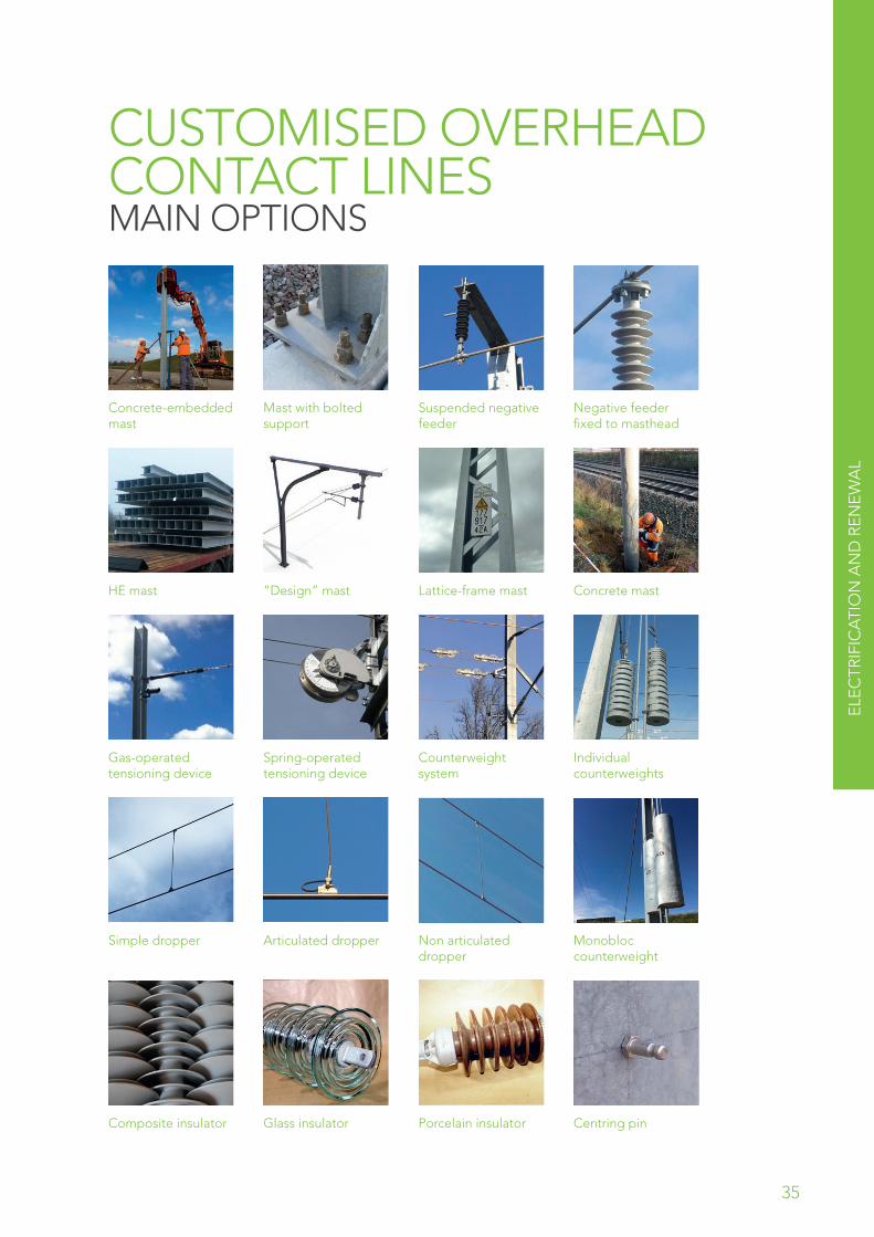
CUSTOMISED OVERHEAD CONTACT LINES MAIN OPTIONS
Concrete-embedded mast
Mast with bolted support
Suspended negative feeder
Negative feeder fixed to masthead
HE mast “Design” mast Lattice-frame mast Concrete mast
Gas-operated tensioning device
Spring-operated tensioning device
Counterweight system
Individual counterweights
Simple dropper Articulated dropper Non articulated dropper
Monobloc counterweight
Composite insulator Glass insulator Porcelain insulator Centring pin
35
ELE
CTR
IFIC
ATI
ON
AN
D R
EN
EW
AL

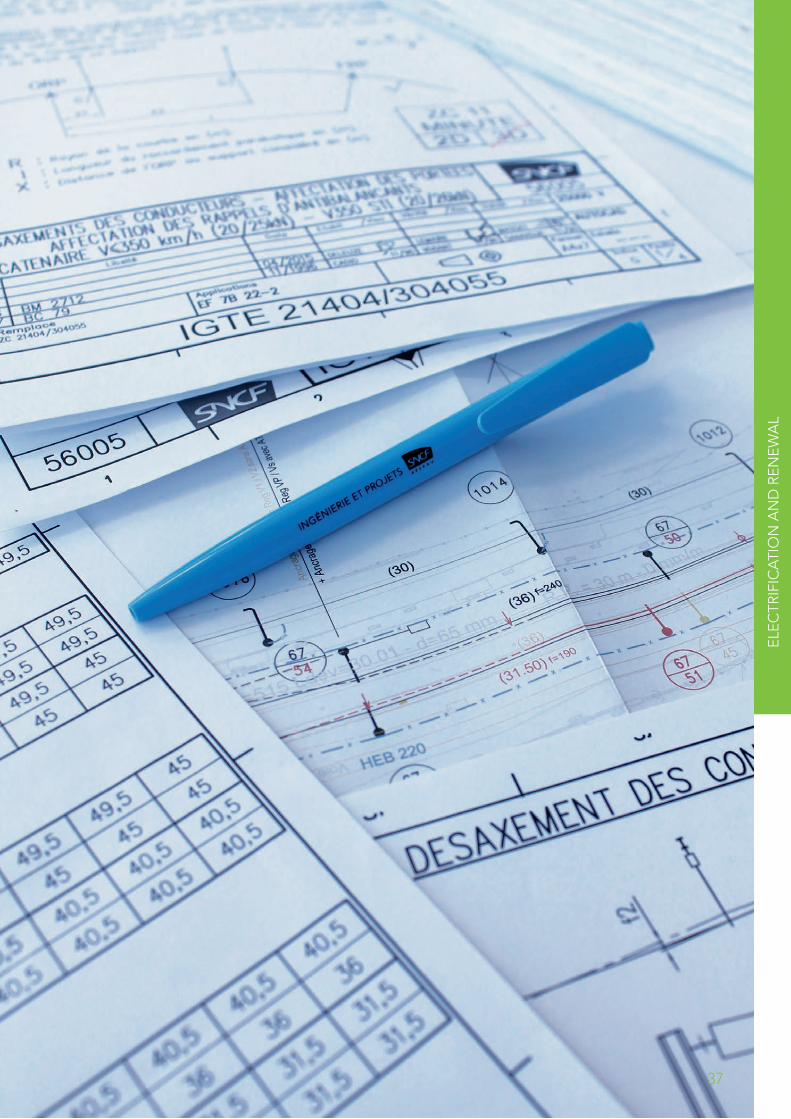
OVERHEAD LINE PLANS & DIAGRAMSFor the design of each of these overhead line types there exists a series of functional diagrams produced by the Design Department in accordance with its quality assurance procedures.
A COLLECTION OF PLANS COMPRISES...
A system TSI-validated in the design phase.
The possibility of support: during the technical implementation phase, in obtaining sub-system TSI certification in the implementation phase, with the new technical developments to be applied as part of a project.
Adaptable technical solutions that can reap the benefits of all the feedback acquired by the French rail infrastructure manager.
A set of overhead line components designed in accordance with the European standards in force, with a wide choice of potential suppliers (few exclusive suppliers).
The guarantee of simple implementation studies for greater project efficiency.
Guaranteed performance standards.
Guaranteed longevity.
Possibility of combining all this with a nomenclature (list of parts and their characteristics). Also, possibility of support in the product type approval process and qualification of production sites.
Ce document est la Propriété de la SNCF-Division ZC1 Reproduction, communication à des tiers et utilisation interdites sans autorisation écrite (Loi du 01 juillet 1992).
NOTE DES PRINCIPES D’EQUIPEMENT CATENAIRE SNCF V200 STI 56005
Ind. Libellé Date Etabli /Visa Vérifié /Visa Validé /Visa
25000V
/ BC 668 12/2010 DELEUZE LIGONNIERE GEHL
WORD V 97 – SR2
Remplace Applications/EF 7B 22-1 Format
A4x29Echelle
----
IGTE 21400/300150 Indice
/Feuille
1/28
1. Functional references
3. Overall equipment diagram
2. Functional diagram of parts
4. Detailed parts diagram. Technical and general specifications
36
37
ELE
CTR
IFIC
ATI
ON
AN
D R
EN
EW
AL

MAINTENANCE AND PARTIAL REPLACEMENT MAINTAINING THE EXISTING OVERHEAD LINE NETWORK
38

MA
INTE
NA
NC
E A
ND
PA
RTI
AL
RE
HA
BIL
ITA
TIO
N
39

THE FRENCH NATIONAL RAIL NETWORK TODAYFor more than a century, the French rail network has been the birthplace of new and emerging electric traction technologies.
Today the network totals 16,000 km of electrified lines, 90% of which are double track, and can boast some 70 different types of overhead contact line.
EXPERIENCE AND FEEDBACK
All these different technical solutions add up to an extraordinary collection of assets that, combined with a solid experience of maintenance and new design technologies, make infrastructure manager SNCF Réseau a past master in continuous product enhancement:
Optimising and standardising components in the design phase,
Driving down procurement and erection costs,
Optimising preventive maintenance cycles,
Suitably adapted product replacement (and or recycling) solutions
MAINTENANCE POLICY
The catalogue sets out details of the major and minor replacement and renewal operations that correspond to the condition of the particular assets and the target performance standards (speeds, traffic volumes).
These operations are designed to maintain overall quality and comply with predefined principles and equipment standards.
RENEWAL OF THE LOWER PART OF A 25,000 V OVERHEAD LINE STRUCTURE
For 25 kV AC, the process consists of replacing the lower part of the overhead line supporting structures to bring them up to TSI performance levels.
This is particularly useful solution on lines where performance needs to be improved but where the condition of the structures does not justify complete OCL renewal.
Optimised lifecycle costs (LCC)
40

OVERHEAD LINE DESIGN TECHNICAL CHARACTERISTICS
TYPE TSISPEED
TARGET50 150 250 350
25,0
00 V
AC
Type 98 V160 TSI
North-East V160 TSI
Type 82 V200 TSI
Type 85 2011/274/EU
V200 TSI
1,50
0 V
DC
Ex-Midi CSRR TSI
CNCSRR TSI or CN TSI
LGVA (Ex-Tours bypass)
-
Key: Certified Certification pending
41 MA
INTE
NA
NC
E A
ND
PA
RTI
AL
RE
HA
BIL
ITA
TIO
N

TYPE 98 OCL 25,000 V AC
ELECTRICAL POWER
25,000 V AC 50 Hz
MAXIMUM SPEED 140 km/h
1ST COMMISSIONING DATE
1998
USE Conventional lines
PANTOGRAPHS ACCEPTED 1,450/1,600 mm
TENSION REGULATION RANGE
70 °C
TSI No
NORTH-EAST OCL 25,000 V AC
ELECTRICAL POWER
25,000 V AC 50 Hz
MAXIMUM SPEED 160 km/h
1ST COMMISSIONING DATE
1952
USE Conventional lines
PANTOGRAPHS ACCEPTED 1,450/1,600 mm
TENSION REGULATION RANGE
70 °C
TSI Yes, post upgrading
42

TYPE 85 OCL 25,000 V AC
ELECTRICAL POWER
25,000 V AC 50 Hz
MAXIMUM SPEED200 km/h 220 km/h for TGV
1ST COMMISSIONING DATE
1985
USE Conventional lines
PANTOGRAPH ACCEPTED 1450/1600 mm
TENSION REGULATION RANGE
80 °C
TSI Yes
TYPE 82 OCL 25,000 V AC
ELECTRICAL POWER 25,000 V AC
MAXIMUM SPEED200 km/h 220 km/h for TGV
1ST COMMISSIONING DATE
1982
USE Conventional lines
PANTOGRAPHS ACCEPTED 1,450/1,650 mm
TENSION REGULATION RANGE
80°C
TSI Yes, post renewal
43 MA
INTE
NA
NC
E A
ND
PA
RTI
AL
RE
HA
BIL
ITA
TIO
N

EX-MIDI OCL 1500 V DC
ELECTRICAL POWER 1, 500 V DC
MAXIMUM SPEED 160 km/h
1ST COMMISSIONING DATE
1922
USE Conventional lines
PANTOGRAPHS ACCEPTED 1,950 mm
TENSION REGULATION RANGE
Not relevant
TSI No
COMPOUND OCL 1500 V DC
ELECTRICAL POWER 1,500 V DC
MAXIMUM SPEED200 km/h 220 km/h for TGV
1ST COMMISSIONING DATE
1924
USE Conventional lines
PANTOGRAPH ACCEPTED 1,600/1,950 mm
TENSION REGULATION RANGE
45 °C
TSI pending
44

LGVA OCL 1500 V DC
ELECTRICAL POWER 1,500 V DC
MAXIMUM SPEED 270 km/h
1ST COMMISSIONING DATE
1990
USE HSL connecting lines
PANTOGRAPHS 1950 mm
ACCEPTED 1,950 mm
TENSION REGULATION RANGE
80 °C
TSI No
45 MA
INTE
NA
NC
E A
ND
PA
RTI
AL
RE
HA
BIL
ITA
TIO
N

CERTIFIED SKILLS & ABILITIESI&P maintains and enhances the skills and abilities of its all staff in order to achieve excellence. The results of these efforts have been certified by an independent body.
46

GLOSSARYAT : Tensioning equipment
CN : “Normal” overhead contact line
CSRR : Simple reinforced and tensioned overhead contact line
CSS : Central Sub-station
DGII-TE : SNCF RESEAU’s Industrial & Engineering Headquarter, Electric Traction Department
EF : Finite elements
LAC : Aerial contact line
LCSR : Single tensioned contact wire
LGVA : Atlantic high-speed line
OCL : Overhead Contact Line
RFN : French National Rail Network
TSI : Technical Specifications for Interoperability
47

CONTACT
SNCF RÉSEAUINDUSTRIAL & ENGINEERING SERVICESFIXED ELECTRIC TRACTION EQUIPMENT DEPARTMENT
TEL.: +33 (0)1 41 62 05 77E-MAIL: [email protected]
Photos: SNCF-02-2017Designed and printed by: KelCom.fr
WE’RE HERE:6 AVENUE FRANÇOIS MITTERRAND93574 LA PLAINE SAINT-DENIS CEDEX FRANCE