
ENHANCEMENT PERFORMANCE OF ROAD RECOGNITION SYSTEM OF AUTONOMOUS ROBOTS IN SHADOW SCENARIO
Upload
khangminh22Category
view
0download
0
AN INDUSTRIAL PALLETIZING SYSTEM FOR INDUSTRIAL ROBOTS
by
Peter Mertens
Thesis submitted to the Faculty of
the Virginia Polytechnic Institute and State University
in partial fulfillment of the requirements of the degree of
Master of Science
in
Industrial Engineering and Operations Research
Dr. M. S. Jones
APPROVED:
Dr. M. P. Deisenroth, Chairman
November 1985
Blacksburg, Virginia
Dr. S. W. Zewari

An Automated Palletizing System For Industrial Robots
by
Peter Mertens
Industrial Engineering and Operations Research
(Abstract)
A study was conducted to set up an automated system for the use of
industrial robots in frequently changing palletizing applications.
The system consists of an industrial robot (IBM Manufacturing
System 7545), an IBM PC, a gripper carousel storage system, a quick
change mechanism, and a robot gripper. The system is set up to
enable a minimum of operator intervention. Hardware aspects
(quick change mechanism and gripper storage) as well as dynamic
software generation for different palletizing applications were
considered in the research project.
The research effort involved both software and hardware
developments. A FORTRAN program was developed to generate
pallet patterns based on dynamic input of package and platform
parameters. The geometric pattern was then used to create an

appropriate AML/E program to drive the robot through the desired
motion sequence. This program was then compiled and downloaded
to the robot. Hardware aspects of the research were focused on the
development of a system to permit dynamic changing of end of arm
tooling. This included development of a quick change mechanism
and a gripper carousel storage system. The quick change mechanism
included interfaces for electronic signals, air and vacuum lines. A
vacuum gripper was also designed for package handling.

Acknowledement
The author wishes to express hearty gratitudes to his chairman, Dr.
Michael P. Deisenroth for his invaluable guidance, support, and
patience; to Dr. Marilyn S. Jones and Dr. Said W. Zewari for their
recourseful ideas and advice.
Thanks are also due to Keith Wright and Bart Moore of the IEOR
Machine Tool Laboratory at Virginia Tech for their supporting
input in machining and assembling the research equipment.
iv

TABLE OF CONTENTS
Chapter I. Introduction ........................................... 1
1.1 Background Information ..................................... 1
1. 2 Issues in Present Study .................................... 3
1.3 System Environment and Setup ............................... 5
Chapter II. Literature Review ...................................... 7
2.1 General Robot Palletizing/Depalletizing Applications ....... 7
2.2 Pallet Pattern Evaluation ................................. 13
2.3 Quick Change/Interfaces ................................... 15
2.4 Robot Languages and Palletizing ........................... 18
2.5 Concluding Remarks on the Review of Literature ............ 22
Chapter III. Software System Design ............................... 24
3.1 Pallet Pattern Generation ................................. 24
3.2 An Alternative Algorithm .................................. 28
3.3 Comparison of the Algorithms .............................. 31
3.4 Robot Motion Command Generation ........................... 32
3.5 Description of Software System ............................ 35
3. 6 An Example Application .................................... 39
3.7 AML/E Subroutines and Descriptions ........................ 43
Chapter IV. Hardware System Design ............................... 52
4.1 Palletizing Gripper Design ................................ 53
4.2 Quick Change Mechanism .................................... 55
V

4. 3 Carousel Design ........................................... 65
Chapter V. System Testing and Demonstration ...................... 75
5 .1 Perform_ance Testing ....................................... 75
5. 2 System Demonstration ...................................... 82
Chapter VI. Conclusions and Recommendations ....................... 86
6.1 Critique and Extensions ................................... 86
List of References ................................................ 90
Appendix A. Interlock Program .................................... 92
Appendix B. Combined Heuristic .................................. 111
Appendix C. AML/E Program ....................................... 133
Appendix D. Mechanical Drawings ................................. 138
Vita ............................................................. 154-
vi

LIST OF ILLUSTRATIONS
Figure 3.1 Pallet Sections ...................................... 27
Figure 3.2 Pallet Pattern ....................................... 29
Figure 3.3 Interlock Pattern .................................... 42
Figure 4.1 Palletizing Gripper .................................. 54
Figure 4.2 Quick Change ......................................... 58
Figure 4.3 Locking Mechanism .................................... 60
Figure 4.4 Calculation Explanation .............................. 62
Figure 4.5 Gripper Carousel ..................................... 67
Figure 4.6 Explosion Drawing .................................... 72
Figure 5.1 Robot Workcell ....................................... 83
vii

LIST OF TABLES
Table 3 .1 User Options ...................................... 37 - 38
Table 5 .1 Test Summary ........................................... 81
viii

Chapter I
INTRODUCTION
The purpose of this chapter is to present to the reader basic
material in robot technology and industrial palletizing applications.
E. Grab [6] points out that the changing competitive conditions in
industry today require new technologies to play a more important
role in production and storage processes as compared with the
situation of the last decade. Especially in the field of modern
information systems, new areas of application for robots and
flexible automation in material handling must be developed to their
fullest potential.
1.1 Background Information
According to Engelberger [5], one common method of classifying
industrial robots is to examine the type of control system
implemented to guide the robot through the desired operation.
Limited sequence robots employ a system of mechanical stops or
limit switches to control the movement of arm and gripper. They
are the least sophisticated species of the robot family. Point to
point robots are able to move to various positions between the limits
of motion along each axis. Control is associated with the
positioning of the robot at the completion of each motion. The path
taken between each motion is arbitrary. The continuous path
1

2
control system is needed for applications in which it is necessary
not only to control the start and finish points of a motion path, but
also the path traced by the robot hand as it travels between these
two extremes. Both point to point robots and continuous path
control systems utilize servo control in obtaining the desired
positioning.
The sequence of motion associated with a robot application must be
programmed by the user of the system. As the application changes,
the new or modified task requires reprogramming. A simple change
in the location of a part feeder or the orientation of a holding
fixture requires program modification. Current programming
techniques often require the use of the robot in the actual
production environment. "Teach pendant" programming allows the
operator to drive the robot through the desired sequence of motions
while identifying the end point of each path. Considerable
production time can be lost during this programming process.
Palletizing refers to the process of stacking boxes, packages or
finished parts on a platform or pallet. It is an important ingredient
in an automated factory [16] because:
1. Space is used as efficiently as possible.
2. Parts, ordered in a pattern, facilitate pickup in the next
manufacturing stage. This eliminates the need for tactual
devices or computer vision.
While automatic palletizers are available for high volume long run

3
operations, robots offer an alternative for lower volume production.
According to Engelberger [3] and Abair [1], the most favorable
conditions for using an industrial robot when designing palletizing
patterns are given when the patterns change frequently and the
process does not exceed a speed of 5 to 10 parts per minute. The
development of a technique to improve the process of programming
a palletizing operation would greatly increase applicability of
robotics to this industrial task.
Some robot vendors offer special software options for palletizing
operations. This is usually general in nature and results in a
rectangular pattern of evenly spaced items.
An optimal pattern will only be reached in specific pallet and box
configurations. In addition to time delays in manual software
setup, hardware configurations in integrated palletizing systems
require further improvement. The need for an interchangeability of
end effectors is strongly related to automated systems so that idle
time caused by manual gripper changes may be avoided.
1.2 Issues in Present Study
The purpose of the study was to demonstrate a method of tying
together material handling, flexible automation, and a combination
of on-line and off-line programming. This involved the

4
development of a "software package" to create an "optimal" pallet
pattern and the corresponding robot control path. Additionally
quick change mechanism and storage facilities for grippers were
investigated, and owing to the necessity of special requirements, new
designs were made and tested.
Frequently changing palletizing applications were selected to be the
research framework, because they provide an ideal area to be subject
to automation. The conducted case study proves that robot
application can be optimized by avoiding time consuming off-line
programming procedures and introducing automatic gripper change
systems. Since some quick change mechanisms have already been
introduced to the industrial market, the major issue in this research
is to simplify the locking and unlocking mechanism and to make
quick change systems generally applicable. One weakness of the
commercially available systems is their restriction to be
implemented only in certain predefined environments: some
equipment is only adaptable to light assembly robots (Intelledex
Inc.), others are only adaptable to medium sized or heavy duty
robots (EOA Systems Inc.).
It is the scope of this research to close the gap between these two
extremes to allow a quick change system to be used for small to
medium sized robots. Research to avoid long programming efforts
by employing a general software to create the robot control
program, is lacking in literature. Robots are still programmed for

5
every changing situation. The present study emphasizes the
development of a general palletizing software system. User input
data is used to generate appropriate control commands thus
relieving the operator of any programming task. Required input
data is to be clearly defined and reduced to a minimum, so that even
untrained personnel can handle the appropriate software.
1.3 System Environment and Setup
In order to demonstrate the feasibility of the integration of an
off-line pattern generation process with a standard industrial robot,
a workcell was created. The system consists of commercially
available equipment, specially machined parts and system modeling
components. Although limited in size, the setup was representative
of an industrial palletizing operation. The system components
included:
1. IBM 7545 robot with Intel 8080 controller.
2. IBM PC with 256 Kbytes Memory and two disk drives.
3. Fischer Technik conveyor.
4. Vacuum palletizing gripper with built-in sensor capabilities.
5. Quick change gripper adapter.
6. Carousel gripper storage.
7. Wooden blocks serving as substitutes for boxes.
The IBM 7545 Manufacturing System was selected for this research
because of its relatively low cost, its (for a small robot) high

6
payload capacity, the high repeatability(+/- 0.002 inch), and its
communication capabilities. It is programmed with an IBM
Personal Computer (PC), using Version 4 of the AML/E robotics
language. Some of the AML/E features are listed below:
1. Editor create and edit programs quickly.
2. Teachmode with graphic display of workspace and digital
output control.
3. English-like commands, including commands for straight-line
moves, palletizing support, and communication features.
4. Programmable speed.

Chapter II
LITERATURE REVIEW
The following literature review is subdivided into three major areas:
1. General robot palletizing/depalletizing applications.
2. Pallet pattern evaluation.
3. Interchangeable grippers and adapters.
2.1 General Robot Palletizing/Depalletizing Applications
The article, "Palletizing and Unitizing: How Robots Stack Up" [2],
gives a general overview of palletizing techniques and the problems
accompanied with this task. According to the authors, robots will
never displace high speed palletizers, because the robot is still a
low speed handling device. Robots, however, do have an appropriate
place in industrial palletizing. Robots are not only able to position
parts of any size, shape or weight precisely, they can also insert
dunnage. Because of their flexibility, robots can stack cases of
different products from a single infeeding conveyor onto several
palletizing stations. In addition to these advantages, the
palletizing robot is well suited to working with other automated
equipment, as long as they are synchronized through bar codes or other
means of identification. To enable the end effector to pick up
multiple cases, a vacuum gripper is often the only choice.
7

8
The problem with this kind of grippers is that their tasks are limited
to case weights of about 50 lbs. or less. If a heavy load has to be
handled, a combination mechanical and vacuum gripper is often a good
solution to this problem.
A comparison of high case palletizers with palletizing robots reveals
that the hardware automation is faster, but it is not able to handle
a wide variety of patterns and requires a great deal more floor
space than a robot. The programmability and the gripper design
allow the software automation to handle many different patterns.
Additionally automatic palletizers are limited to handling boxes or
cartons, while the industrial robot can manipulate a product
directly.
Because of this wide range of variety, the development of efficient
software remains a problem, since it is still impossible to purchase
appropriate software directly from the retailer. The authors are of
the opinion that the unique nature of most unitizing and palletizing
applications is responsible for the need for special customized
grippers and software.
Bengt Seger's [14] case study takes a complex palletizing application
into consideration. The robot is applied to a bottling process. One
type of box weighs 8 kg and arrives at the pickup station at a rate
of 10 per minute, which amounts to 38,400 kg during an 8 hour
shift.

9
A special gripper was designed for the 40 different sizes of cartons.
The gripper is described as having two fingers. The upper finger
serving as a holding plate and the lower one serving as a carrier.
The lower finger can slide backwards on linear bearings, allowing
the package to be placed on the pallet correctly. All 40 box sizes
require separate programs, written and stored on magnetic tape.
The author describes the programming operation as a time
consuming task of 0.5 to 2.0 hours per program.
In Abair's [1] view, palletizing is an ideal area for automation,
because all applications have at least one of the following
characteristics in common:
1. Repetitive routine.
2. Multi-shift operation.
3. High volume output.
4. Strenuous labor-intensive method.
5. Tedious operations.
If short run products of various sizes with different pallet patterns
are produced individually or simultaneously, robots are said to be
cost efficient solutions. A typical robot cycle in a palletizing
application is approximately 10 to 15 seconds from pickup to
pickup. In order to optimize the path of the cycle, the entering
parts have to be oriented beforehand. A suitable alternative for
reducing overall cycle time is to provide a secondary palletizing
location. Once the first load is completed, the robot can move to

10
the alternate location, and the operation can be resumed. The
author found mechanical grippers to be the most useful although
clearance requirements may prove a mechanical device to be
unusable. However, the effect of inertia and accelerating forces
have to be evaluated to ensure a secure transport when using
magnetic or vacuum grippers.
Norbert N. Staufer [16] expresses the need for an ordered
environment as an important prerequisite in the automated factory.
Parts and material should be oriented accurately to make succeeding
operations faster and easier. Palletizing and depalletizing
operations accomplish these demands as an alternative to vision
systems or other sensing techniques. According to Staufer, software
changes, required in palletizing applications, are time consuming
and have to be reduced to a routine exercise, which is limited
essentially to indicating the orientation of the load, number of part
locations per layer, and number of layers.
E. Grab [6] points out that the demand for further flexibility,
reliability, and optimally of the storage capacity in the buffer area
necessitates the increased use of automation systems between
production and storage areas. A situation analysis of different
representative production and logistic areas resulted in the
realization that industrial robots are especially qualified in
situations where the process time is defined by the machine production
rate and limited by human work force capabilities. These

11
characteristics are common in palletizing, depalletizing, loading,
unloading, and collecting applications. Traditional single purpose
units are said to be well suited for batch production but include
significant disadvantages: the unit is usually constructed for one
specific product and the transferring to new product modifications
is limited. The proposed 11Unimation 11 robot palletizing center (RPG)
includes the following advantages over the conventional system:
1. Universal use in spite of different, permanent changing
products and variable quantities.
2. Off-line programming of different palletizing
arrangements.
3. Easy alteration of changing production software.
The RPG system is guided by a supervisory controller. This
computer controls all peripheral equipment for the loading process
in which shipper containers are filled and then received by the
UNIMATE robot. The pneumatic, parallel gripper is sensor
equipped.
Ray Hinson [8] describes a palletizing application which is planned
to be subject to automation. Currently the operation is performed
manually. The same palletizing pattern is used until three stack
levels have been placed on the pallet. In the succeeding step, the
operator places a separator sheet over the stacked layer. The
subsequent layer is palletized which is rotated 180 degree to provide
stability to the pallet load. A tie sheet is placed over the second
layer before the third and final level is palletized and rotated 180

12
degrees from the second layer. Based on individual stack weights
of approximately 45 lbs, operators handle 28 tons of goods per shift.
Consideration must be given to all of the sensory capabilities
employed and the coordination necessary to perform the task by
means of robot automation. Removing as many variables as possible
while minimizing the need for decision making can be accomplished
by the creation of an orderly environment. Positioning of the pallet
can no longer be an approximation. Also, further restrictions must
be placed on the positioning of product stacks at the end of the
conveyor. Additionally, if the requirement for dunnage sheet
placement is to be fulfilled by the robot, the locating and
positioning of the dunnage sheet supply is important. The presence
of both pallet and product can be sensed by using contact switches
which serve as substitutes for maintaining visual contact.
All sensory input is fed through a programmable controller to
coordinate the system components and provide signals to initiate
robot activities. The weight and design of the tooling will affect
the performance of the robot in various ways. It can have a
negative impact on robot's performance by being too large or too
heavy, which will result in slower speed, or it can reduce the
payload capability of the robot by introducing moments and loads
which are out of its range of capacity.
An interesting approach of robot communication with external

13
devices in palletizing applications is described by G.S. Vasilash [19).
He is of the opinion that repetition jobs should be handled by
machines instead of human beings to improve efficiency and work
life quality. The particular application is described as follows:
palletizing is performed 24 hours a day, seven days a week. A
typical pallet load is 25 layers, each layer having 31 tubes. A
counter is used to keep track of the number of layers placed on the
pallet. Once the pallet is stacked to capacity, the conveyor is
energized by a controller output signal to replace the full pallet
with an empty one. The new pallet operates a limit switch that
stops the conveyor and signals the robot to proceed.
The parallel tubes are automatically moved closer together into a
queue at the end of the conveyor. When the queue consists of 31
tubes, the head tube tips a limit switch to signal the robot that it
can pickup a load. The switch's second function is to operate a gate
to halt the 32nd tube till the pickup location is cleared again.
Before employing new robots to this palletizing task, extensive
economic evaluations were conducted to compare robots to
alternative automation equipment. It was established that the
gravity operated conveyors offered higher economic justification,
but were not able to handle an anticipated production-rate increase.

14
2.2 Pallet Pattern Evaluation
During the palletizing process, cartons or boxes are arranged in a
pattern on a platform. Two properties of the pattern are important.
The arrangement must attempt to make maximum use of space
available. This will permit maximum utilization of the space when
the product is shipped. Secondly the arrangement of the items must
provide stability to the load as layer is stacked upon layer. This
can be accomplished by changing patterns between layers.
Alexis Kulick (11] describes a computer simulation to develop pallet
patterns. Since manufacturing is subject to frequent changes, the
cost and possible inaccuracy of creating these patterns should be
reduced significantly by means of computers. Each new shipper
design may result in a new pallet pattern.
This paper deals only with the interlocking pattern, i.e. four of the
five basic patterns have not been considered. Kulick also mentions
that this simulation heuristic may not offer optimal pallet
utilization. The interlocking character is achieved by turning each
layer 180 degrees from the layer below, using the same pattern.
Harold J. Steudel [17], describes a heuristic to determine a loading
pattern which tends to minimize the amount of unused pallet deck
board area. To solve these two dimensional problems, dynamic
programming is first used to determine four optimum sets of length

15
and/or width placements of the small rectangles (shippers) along the
inside edges of the pallet. In the second phase, the optimum
arrangement of rectangles along the perimeter is projected inward to
fill in the center portion of the large rectangle so as to minimize the
amount of unused area.
To establish the necessary geometric relationship, a pattern layout is
designed to set up a maximum of four individual rectangular blocks
of shippers. During the second phase of the model, two potential
problems must be considered. For one, a condition of overlapping or
mutual interference among the blocks could occur. The second
problem is that the inward projections could result in a layout
pattern with a central hole larger than a box. Certain procedures
are established to solve interference and central hole problems.
By comparing these results with the results recommended by the
U.S. Navy Supply Research and Development Facility, Steudel
found that his algorithm exceeds the U.S. Navy standard by an
average improvement of 10.4 percent in deck board utilization in 64
of 182 cases. The computer code for the algorithm is regarded as
quite efficient and requires a total memory capacity of 14 K words
and approximately 1.25 CPU seconds ( Xerox Sigma 9) for any of
the tested problems.

16
2.3 Quick Change Grippers/Interfaces
The authors of the article "Intelligent Interchangeable Robotic End
of Arm Tooling [3]" point out that the role of flexible automation in
industrial applications, including assembly and part handling, will
expand rapidly with the commercial availability of
computer-controlled interchangeable robotic end of arm tooling
systems. A quick change adapter, mounted to the robot arm and to
the end effector, provides the capability of performing multiple
tasks in a single work station with an economic justification. The
robot manufacturers are considered to be responsible for the
existing gap in arm and end effector technology, because they have
rushed to expand the robot technology but have overlooked the end
effector research and development programs. The authors contend
that this mistake is one reason for the slow growth of flexible
automation in the U.S. Robot applications are usually limited to the
implementation of tools which can perform only one task. The
ability of executing multiple tasks within a single work station will
add more product value and thereby emphasize cost justification.
The described quick change adapter still has the disadvantage of
being limited to a special range of application.
The article "Quick Change System for Robots" [20] asserts that in
addition to the quick change adapter, a holster system for storing
the end effectors is needed. It is necessary to equip the adapter
with electrical and air connections, and it might even be necessary

17
to have access to hydraulic connections. The physical dimensions of
the adapter described are quite large and limit its use to heavy duty
jobs. The holster design must position the end effector with
sufficient accuracy so that the robot can successfully change end
effectors.
It is stated that the locking/unlocking mechanism must meet
demanding requirements. It must be robust, lock and unlock with
exceptional reliability. Ideally it has to be small and light weight
and operate with shop air. Principles of kinetic energy are
employed to enhance the capabilities of a small air vane actuator so
as to ensure reliable unlocking and firm locking procedures. This
technology requires a quite complex mechanism that must be
purchased from specialized vendors.
Allen J. Wright [21] maintains that the key area of human
versatility, or the ability to use several tools at a work station can
be related to programmable automation by introducing
interchangeable grippers. The following design objectives were
considered necessary for the successful implementation of an end
effector exchange mechanism:
1. Light weight.
2. Axial accuracy.
3. Longitudinal accuracy.
4. Rotational accuracy.
5. Coupling stiffness.

18
6. Torque capacity.
7. Connection of pneumatic and electric lines.
8. Full rotation capability of pneumatic and electric
lines.
9. Easily adaptable to a variety of configurations.
Ellen J. Kehoe [10] illustrates that recent advances in end of arm
tooling technology have broadened the choices available.
Developments have been significant in the areas of interchangeable
fingers and hands, sensory feedback capabilities, multi-fingered
configurations, and the availability of standard models. As robots
are called upon to perform more and more sophisticated, human-like
tasks, expertise in designing and selecting robotic end of arm
tooling is maturing accordingly. The combination of
computer-sophistication and quick change tooling is also considered
to offer increased flexibility adoption. The Quick Change adapter
model from EOA Systems Inc. (Dallas, Texas) represents one
example of interchangeable gripper technology. Configured to
specific parts, this system can consolidate the palletizing of a
low-volume product line into a single cell. Routing tools can be
used in a single workcell while the component remains stationary.
This precludes the need for additional robots.

19
2.4 Robot Languages and Palletizing
To make the palletizing software package as generally applicable as
possible, different robot programming languages were investigated
as to their implementation of the palletizing function. Robot
programming languages can, according to Snyder [15], be subdivided
into four major groups:
1. Task oriented: AUTO PASS.
2. Structured programming level: AL, MCL, MAPLE, PAL
HELP, AML, KAREL.
3. Motion level: VAL, EMILY, RCL, SIGNAL, RPL, ANORAD.
4. Point-to-Point level: FUNKY, T3.
It is possible, though inconvenient, to implement a point-to-point
level language in the manner done in this research, since
programmed robot control is usually achieved by saving a series of
points either by using a teach pendant or by moving the robot
manually. Even though these languages are capable of interacting
with external devices, FUNKY or T3 were hardly applicable to
frequently changing palletizing tasks. One of their major
disadvantages is that the programs generated are extremely long.
The motion-level languages exhibit the following
characteristics:
1. Simple branching provided.
2. Subroutine can be used.

20
3. Parameters can be passed.
4. Sensing capabilities are relatively powerful.
5. The capability of representing and manipulating
frame descriptions is provided.
Most of the motion level languages are based on interpreters or
assemblers, and motion can be specified either in joint coordinates
directly or in Cartesian coordinates. VAL, for example, applies shift
commands to specify different locations. The command SHIFT
PALLET does not cause any motion of the physical pallet; rather, it
redefines a coordinate frame named PALLET. The next time the
robot moves to the PALLET position, it will be a new position. The
APPRO command is not only capable of specifying the desired
position and orientation, it also specifies joint interpolated control.
The VAL structure is relatively similar to the BASIC structure and
would be an excellent alternative to AML/E. A typical VAL
palletizing program is listed below [18]:
1. SETI PX 1
2. SETI PY 1
3. 10 GOSUB 100
4. IF PX= 3 THEN 20
5. SHIFT PALLET BY 100.0,0,0
6. GO TO 10
7. 20 IF PY= 3 THEN 40

21
8. SETI PX= 1
9. SETI PY= PY+ 1
10. SHIFT PALLET BY - 900.0, 100.0,0
11. GOTO 10
12. 100 APPRO CON, 50
13. WAIT CONROY
14. MOVES CON
15. GRASP 25
16. DEPART 50
17. MOVE PALLET: APP
18. MOVES PALLET
19. OPEN!
20. DEPART 50
21. SIGNAL GOCON
22. SETI PX= PX+ 1
23. RETURN
24. 40 STOP
The pallet consists of three rows and three columns of squared
boxes. Lines one and two initialize integer variables which keep
track of the number of parts already loaded in both the X and Y
axes. The GOSUB located in line three calls a subroutine which
will unload one part from the conveyor and place it on the pallet.
The SHIFT command in line five implements a translation of x =
100.0 mm, y = 0, and z = 0. The APPRO function causes motion to
a point 50 mm distant from the Z axis of the designated frame
22
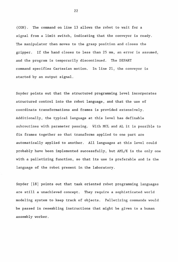
(CON). The command on line 13 allows the robot to wait for a
signal from a limit switch, indicating that the conveyor is ready.
The manipulator then moves to the grasp position and closes the
gripper. If the hand closes to less than 25 mm, an error is assumed,
and the program is temporarily discontinued. The DEPART
command specifies Cartesian motion. In line 21, the conveyor is
started by an output signal.
Snyder points out that the structured programming level incorporates
structured control into the robot language, and that the use of
coordinate transformations and frames is provided extensively.
Additionally, the typical language at this level has definable
subroutines with parameter passing. With MCL and AL it is possible to
fix frames together so that transforms applied to one part are
automatically applied to another. All languages at this level could
probably have been implemented successfully, but AML/E is the only one
with a palletizing function, so that its use is preferable and is the
language of the robot present in the laboratory.
Snyder [18] points out that task oriented robot programming languages
are still a unachieved concept. They require a sophisticated world
modeling system to keep track of objects. Palletizing commands would
be passed in resembling instructions that might be given to a human
assembly worker.

23
2.5 Concluding Remarks on the Review of Literature
While the industrial robot will not replace automatic palletizers in
the foreseeable future, there are many areas of applications in
palletizing for todays robots. The programmability and flexibility
of the robot are ideally suited for operations that have frequent
changes or slower cycle times. Additionally the robot is capable of
direct part handling and is suitable for inprocess palletizing while
automated systems are limited to finished products that have
already been packaged.
All of the authors cited in section 2.1 agree that software
development for palletizing applications still has major drawbacks.
Most vendors do offer some solution packages, but these must still
be customized for each different application. The articles reviewed
which discuss pallet patterns give some examples of algorithms that
can be applied to this situation, but the latter are not integrated
into robot software.
The literature reviewed in the third section of Chapter II
emphasizes the need for research in this special field of flexible
automation. All articles reviewed describe already in existence
equipment but show clearly that an all-purpose system is still not
commercially available. Examples of general palletizing algorithms,
used in robot control, are completely lacking in literature on this
subject.

Chapter III
SOFTWARE SYSTEM DESIGN
The software system developed in this research consists of three
parts. A pallet pattern generation program utilized user input data
to generate a desired pattern using the algorithm as presented by
Kulick [11], or using a newly developed combined heuristic. The
established pattern was then used as input for generating the
necessary robot control commands in the AML/E robot programming
language. An IBM PC batch file then controlled compilation and
downloading of the file to the robot control system. The software was
run on an standard IBM PC with 256 Kbytes of memory, dual floppy disk
drives and a color adapter and monitor. The software system was
developed in a modular fashion to permit a variety of algorithms to be
included.
3.1 Pallet Pattern Generation
AML/E provides the user with a palletizing function to be used easily
in applications not subject to frequent changes. Its major weaknesses
are a lack of flexibility and a low average pallet utilization caused
by the fixed nature of the pattern. IBM dictates the use of an
rectangular pattern, independent of pallet and box size ratio.
Changes in pattern geometry or stacking sequence can only be made
through increasing the complexity of the program structure. To use the
24

25
AML/E palletizing support, the programmer must define the lower left
corner point of the pallet, the lower right corner point, the upper
right corner point, the number of parts per row, and the total number
of parts per layer. If the number of parts per row and the total
number of parts per layer are identical, the AML/E palletizing support
cannot be used, because the controller interprets this configuration
as a data error, i.e. a one-row layer cannot be stacked. The
palletizing function may be used in applications with customized
pallet forms and dimensions, but not as a general purpose solution for
pallet pattern generation.
The interlocking pattern [11] consists of layers of shippers, placed
in two directional patterns. To create the interlock, each layer is
stacked 180 degrees from the layer below using the same pattern. The
interlock receives its support from the overlap of shippers between
two layers. The height dimension of the boxes will always remain
perpendicular to the pallet.
The implemented heuristic [11] divides the pallet into two sections.
The shippers in one section are perpendicular to the shippers in the
other. There are two possible ways of "cutting" the pallet into two
rectangular divisions: parallel to the long side (length), or parallel
to the short side (width) of the pallet. This is illustrated in
Figure 3.1.

26
Both of the cases cited above are to be considered in the heuristic.
The final size of the sections (for a given pallet) depends on the
shipper length and width. A number of different configurations are
checked, and the pattern with the highest pallet utilization is
selected as a basis for further evaluations. The result is expressed
in the number of boxes perpendicular to the long side (length) and
parallel to the short side (width) for the first pallet section and
parallel to the length and perpendicular to the width of the second
pallet section as shown below:
Example: first section:
x1 number of boxes parallel to width
xz number of boxes perpendicular to length
=> total number of boxes in section I: x1 * xz
Example: second section:
x3 number of boxes perpendicular to width
x4 number of boxes parallel to length
=> total number of boxes in section II: x3 * x4
(See Figure 3.1)

27
Pattern 1
X4 I I
t I LI wq X3
t ----------- -..r:::.
Q .... -i:,
3 X1
1 Length I
X2 I I
Pattern 2
X4 I I
! I LI
WI I X3
..r:::. -------·--·- - -.... C'I C QI
._J
X1
l Width I
X2 I
Nam1 Data I Work Chick Figure 3.1 Pallet Sections

28
3.2 An Alternative Algorithm
An alternative to using the interlock algorithm is the "Two
Dimensional Cutting Stock" algorithm [17]. The pallet loading problem
[17] can be viewed as a special case of the two dimensional cutting
stock problem, where all the objects to be arranged are of identical
dimensions. The objective of this problem is to determine a layout
for which the ratio of unused space to the total area of the pallet is
kept to a minimum. To solve this problem a two phase algorithm has
been developed [17]. Dynamic programming is first applied to
determine four optimum sets of length and/or width placements of the
boxes along the edges of the pallet, as shown in Figure 3.2. The
objective of the algorithm's second phase is to project an optimal
arrangement of the shippers inward to fill the center portion of the
pallet.
To establish the necessary geometric relationships, a pattern layout
is defined as consisting of a set of a maximum of four blocks of
shippers. Overlapping or mutual interference among blocks could occur,
or the inward projection could result in a layout pattern which has a
central hole larger than a box. Both problems must be taken into
consideration and solved to fulfill the requirements.

29
Naml! I Work
Check Figure 3.2 Pallet Pattern

30
The pallet utilization reached with this algorithm was compared to the
pallet pattern recommended by the U.S. Navy Supply Research and
Development Facility. An average improvement of 10.4 % in deck board
utilization in 64 out of 182 cases was established [17]
The second implemented heuristic, developed in this research, was a
combination of "Interlock" [11] and "Two Dimensional Cutting Stock"
[17] algorithm. Both were used as a first starting base to create a
new heuristic. The program divides the pallet into 4 sections, like
the "Two Dimensional Cutting Stock" algorithm, but establishes a
common intersection for all four regions. This guideline was
implemented because it guarantees a high probability for an interlock
pattern in a wide range of cases. The two diagonal opposite sections
have the same patterns but are perpendicular to each other.
The first section is used as a starting point and every possible
combination of boxes in the four regions on the pallet is
enumerated accordingly. The box configuration with the highest
pallet utilization is used to establish the final pattern. The idea
of combining structures of "Interlock" and "Two Dimensional Cutting
Stock" algorithm was based on the acceptance of providing the
interlock advantages by reaching a very high pallet utilization. This
goal was not reached fully, although the heuristic was proved to be a
very useful alternative. The implementation in the overall software
package was established easily, since the system was conducted in a
modular fashion. Except for the actual heuristic section, only minor

31
changes had to be made. The AML/E palletizing function was used for
all four pallet regions individually, and the result is expressed in
the number of rows and columns per region and the total number of
boxes per layer and pallet.
3.3 Comparison of the Algorithms
To evaluate the performance of both heuristics, interlock and
combination heuristic, layout patterns for a 40 inch by 48 inch pallet
were generated in 0.50 increments for items ranging in size from 5.00
inches to 10.5 inches width and from 7 inches to 15 inches in length.
The resulting patterns for 167 cases were then compared in terms of
the number of items per layer to the pallet patterns recommended by
the U.S. Navy Supply Research and Development Facility as reported by
Haynes [7]. The interlock heuristic provided an improvement of 7.34%
compared to the Navy standard and the combined heuristic "only"
reached the Navy standard (99.88% of Navy standard).
A closer look at the results discovered the real strength and
weaknesses of the combined heuristic: the pallet utilization decreases
with increasing box sizes, especially if boxes with 5 to 7 inches
width and 12 to 15 inches length have to be stacked, a utilization
improvement of 3.78% (compared to the U.S. Navy standard) can be
achieved, so that this heuristic can be strongly recommended in
applications with these particular box sizes.

32
3.4 Robot Motion Command Generation
There are basically two ways to implement the outcome of the used
heuristics into the software frame to generate the robot control path
for an "optimal" pattern. For one the geometric location of every
single box for every layer has to be calculated and implemented into
AML/E. Using this method assumes that every shipper transport
requires the generation of at least six AML/E statements:
1. Move the manipulator above the conveyor.
2. GRASP the box.
3. Move the manipulator in positive Z direction.
4. Move the manipulator above the pallet.
5. RELEASE the box.
6. Move the manipulator in positive Z direction.
The maximum AML/E file size restriction allows no more than 800 lines
for personal computers with 256 KBytes memory. When one considers a
pallet load of 10 layers and 40 boxes per layer, the robot control
path will require 2400 statements. Since multiple statements per line
are allowed, the number of lines will be reduced to approximately 600,
i.e. up to 75% of the total editor capacity is utilized solely for the
stacking process.
The second alternative is the use of the AML/E palletizing function.
As the interlock heuristic, for example, divides the pallet into two
sections with rectangular patterns that are perpendicular to each
33
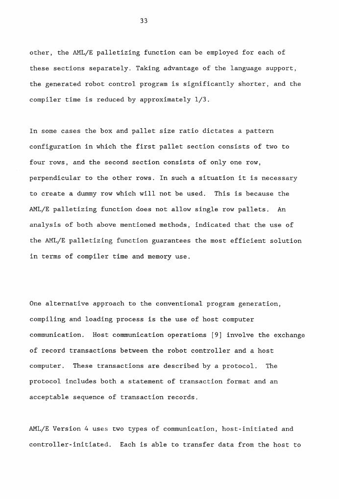
other, the AML/E palletizing function can be employed for each of
these sections separately. Taking advantage of the language support,
the generated robot control program is significantly shorter, and the
compiler time is reduced by approximately 1/3.
In some cases the box and pallet size ratio dictates a pattern
configuration in which the first pallet section consists of two to
four rows, and the second section consists of only one row,
perpendicular to the other rows. In such a situation it is necessary
to create a dummy row which will not be used. This is because the
AML/E palletizing function does not allow single row pallets. An
analysis of both above mentioned methods, indicated that the use of
the AML/E palletizing function guarantees the most efficient solution
in terms of compiler time and memory use.
One alternative approach to the conventional program generation,
compiling and loading process is the use of host computer
communication. Host communication operations [9] involve the exchange
of record transactions between the robot controller and a host
computer. These transactions are described by a protocol. The
protocol includes both a statement of transaction format and an
acceptable sequence of transaction records.
AML/E Version 4 uses two types of communication, host-initiated and
controller-initiated. Each is able to transfer data from the host to

34
the controller (a data drive direction) or from the controller to the
host (a report direction). The data drive direction allows the host
to affect the application that is being executed by the controller.
The communications interface supplied with AML/E Version 4 is a low
level interface used in conjunction with machine language, i.e.
records are transmitted and received in ASCII code.
In this study the controller initiated communication is of major
interest, because it allows the user to change the value of variables
in controller storage without interfering in the application program.
It allows the user to maintain many parameters of point data in the
host computer and to load the points into an application program
before execution is initiated.
Utilizing host computer communication a palletizing program would
permit implementation of the logic to be shared between the host
computer and the robot controller. Actions which do not change, part
pickup, gripper exchange, etc. would be implemented on the robot
controller. The host software would keep track of the pattern point
sequence and geometric data. Commands and pallet points could then be
passed to the controller when applicable. While this approach has
significant merit, it does require the dedication of a host computer
during the operation. Additionally, assembly language interface
routines are necessary to drive the communications process. For these
two reasons, this approach was not taken in this research.

35
3.5 Description of Software System
The pallet generation algorithm and the program to transform the
geometric pattern into AML/E robot motion commands were combined into
a single FORTRAN 77 program and implemented with the MICROSOFT FORTRAN
compiler version 3.2. This program generated the source control
program for the robot by writing into an external disk file. The
autoexecution function for the IBM PC was then used to cause the AML/E
compiler to read the file, create code for the robot controller and
then down load the file for execution. To start program operations,
the personal computer must be connected to the controller; the
controller must be ON LINE, and the manipulator must be powered on.
Boot loading the user disk in drive A causes the "AUTOEXEC.BAT" file
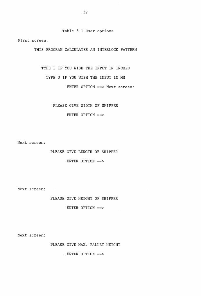
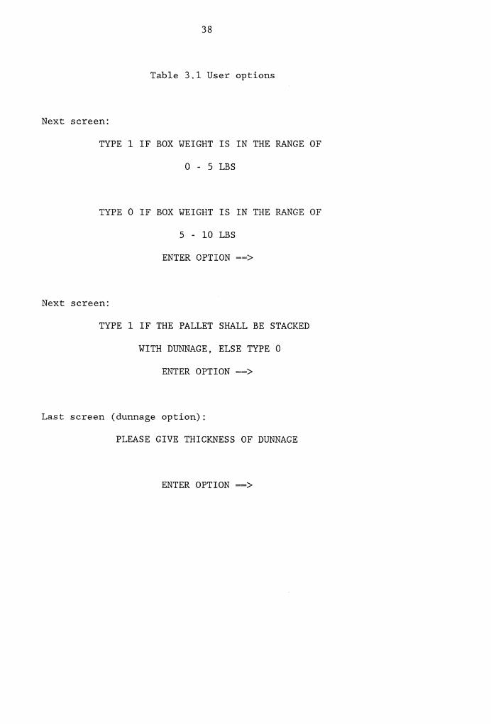
to start the FORTRAN program. In the interactive phase, the user
selects the unit of measurement (inches or millimeters), and is
requested to input data on shipper dimensions and weight, and maximum
pallet height, as well as whether the system is working with or
without dunnage. Table 3.1 illustrates the initial dialog. The
program assures a pallet size of 9.6 inches by 8.0 inches however this
could easily be modified. According to the input data, the heuristic
calculates an optimal interlock pattern and informs the user about
pallet utilization, number of boxes per layer, and total number of
boxes to be stacked.

36
The AML/E control program is then generated in the second phase of the
FORTRAN program and written into the "NEW.AML" file on the user's
disk. The implementation of the AML/E statements was reached by using
Boolean algebraic decision functions and FORMAT statements. Depending
on the input data, only certain parts of the program become active.
If the user decides to work without dunnage, an IF Then statement is
used to skip the program part in which the AML/E dunnage stacking code
is generated. This principles are extensively used throughout the
entire software, so that the development of unused AML/E subroutines
is avoided.
37
Table 3.1 User options
First screen:
THIS PROGRAM CALCULATES AN INTERLOCK PATTERN
TYPE 1 IF YOU WISH THE INPUT IN INCHES
TYPE O IF YOU WISH THE INPUT IN MM
ENTER OPTION--> Next screen:
Next screen:
Next screen:
Next screen:
PLEASE GIVE WIDTH OF SHIPPER
ENTER OPTION==>
PLEASE GIVE LENGTH OF SHIPPER
ENTER OPTION==>
PLEASE GIVE HEIGHT OF SHIPPER
ENTER OPTION==>
PLEASE GIVE MAX. PALLET HEIGHT
ENTER OPTION==>
38
Table 3.1 User options
Next screen:
TYPE 1 IF BOX WEIGHT IS IN THE RANGE OF
0 - 5 LBS
TYPE O IF BOX WEIGHT IS IN THE RANGE OF
5 - 10 LBS
ENTER OPTION==>
Next screen:
TYPE 1 IF THE PALLET SHALL BE STACKED
WITH DUNNAGE, ELSE TYPE 0
ENTER OPTION==>
Last screen (dunnage option):
PLEASE GIVE THICKNESS OF DUNNAGE
ENTER OPTION==>

39
The "NEW.AML" file is opened and closed automatically and includes the
complete robot control program. The "AUTOEXEC.BAT" file initiates the
compiler on the AML/E system disk in drive Band indicates appropriate
options. The robot controller is automatically loaded with the
compiled ASCII file, and the user may begin the cycle by pressing the
following sequence of buttons on the robot control panel:
1. Return Horne.
2. Automatic.
3. Application I.
4. Start cycle
3.6 An Example Application
An example problem was implemented with both pallet pattern
heuristics. It showed that the combined heuristic is most likely to
generate an interlock pattern, when possible. The following input
data was assumed:
Input system inches
Shipper width 2.40 inches
Shipper length 3.20 inches
Shipper height 0.75 inches
Max. pallet height: 3.00 inches
Shipper weight 5 - 10 lb
Dunnage yes
Dunnage thickness 0.1 inches

40
According to the above listed input, the FORTRAN program generates an
AML/E control path to guide the manipulator through the palletizing
task. Both heuristics generate the same interlock pattern for this
particular case and based on this information, the palletizing
sequence is specified. The sequence of steps necessary to perform the
palletizing function is then begun. The manipulator with the quick
change adapter attached, moves above the gripper carousel. The robot
controller then rotates the carousel to the home position and then to
the heavy box gripper position. The manipulator moves down and the
vacuum gripper is locked onto the robot arm. The robot slides the
gripper out of its storage slot and moves in positive Z direction.
The conveyor is turned on automatically, and the manipulator waits for
a box to arrive at the pickup location. If no box arrives within 15
seconds, an attention light informs the operator of the problem. The
operator then corrects the problem and presses the restart button for
normal operating conditions.
As boxes arrive at the pickup point, a limit switch is pressed. This
signals the robot that the box is ready for pickup and also turns off
the conveyor drive motor. When the robot completes the cycle from the
previous operation, it tests the status of the limit switch and begins
a new operation cycle. The arm is positioned to pick up a box, the
gripper is activated, the box is taken to the desired pallet position
and the box is released. This cycle continues until the pattern is
completed. In this example, each layer consists of 10 boxes, stacked
according to the optimal interlock pattern as shown in Figure 3.3.

Name Date
Work
............ +----+-----4Figure. 3.3 Interlock Pattern

42
After each layer is completed, the manipulator moves over to the
carousel and the controller rotates the turn table to the home
position and then to the heavy box gripper slot. The robot arm slides
the gripper in its slot, unlocks the quick change adapter, and moves
in positive Z direction to disengage the gripper. The controller
rotates the carousel to the dunnage gripper below the robot end of
arm.
The manipulator moves down, locks the quick change adapter, slides
the dunnage gripper out of its slot, and moves over to the dunnage
stack. After putting a pasteboard on the current layer, the
manipulator parks the dunnage gripper, retrieves for the heavy box
gripper and continues the palletizing sequence for the next layer. As
soon as a pallet is stacked to capacity, an attention horn signals the
operator to replace the full pallet with an empty pallet and press the
restart cycle button to begin the process again. If the operator
fails to replace the pallet within 30 seconds, the robot parks the
palletizing gripper and moves back to the home position.
3.7 AML/E Subroutines and Descriptions
The most important AML/E subroutines are listed and explained below:
INTERCHANGE_BEGIN_HEAVY:SUBR;
PMOVE (INTER); PAYLOAD (11); SET_HOME; ROTATE (25);
ZONE(l);

43
ZMOVE (MATE); WRITEO (ZYLINDERI,ON); LINEAR (l);
DEIAY (2);
PMOVE (SEMI); PAYLOAD (O); ZMOVE (O); WRITEO (15,ON);
LINEAR (O);
END;
The INTERCHANGE_BEGIN_HEAVY subroutine is used to guide the robot
through the heavy-load-gripper pickup sequence. The end of arm moves
to a point above the carousel, specified by the global variable INTER
in the PMOVE statement. The PAYLOAD (11) statement declares that the
next manipulator move will be executed in a very slow speed. After
the speed has been specified, the SET HOME subroutine is called to
generate a number of pulses to rotate the carousel from an arbitrary
position to the home position.
The next command locates the heavy weight gripper correctly by calling
the ROTATE subroutine and passing the formal parameter 25 to this
subroutine. The ZONE (1) statement assures a high degree of accuracy
for the following moves. The manipulator moves down to mating depth,
which is passed through by the global variable MATE. The DO port 1
(specified by the global variable ZYLINDERl) is closed, so that the
locking cylinder is actuated. The cylinder rod then extends to lock
the quick change adapters, and execution is halted for 2 seconds to
assure that the cylinder rod has been fully protracted.

44
After the robot has slid the gripper out of its holster (PMOVE
(SEMI)), the speed is maximized with the PAYLOAD(O) and LINEAR(O)
commands, and the manipulator moves in the positive Z direction to
avoid collisions with obstructions. The DO port 15 is then closed to
start the conveyor.
SET_HOME:SUBR;
LOOP: WRITEO (STEP,OFF); DELAY (0.1); WRITEO (STEP,ON);
DELAY (0.1);
TESTI (HOMEI,ON,DONE); BRANCH (LOOP);
DONE: BREAKPOINT;
END;
The SET HOME subroutine is used to create a string of pulses to rotate
the carousel from an arbitrary position to the defined home position.
Every WRITEO command is followed by a delay of 0.1 seconds to allow
the manual relay to change its status (from closed to open, or from
open to closed). The DI port 9 is tested after each completed pulse
to see if the home position of the carousel has been reached. As soon
as the limit switch is actuated by the stop, DI port 9 closes and
execution is interrupted. The BREAKPOINT provides the user with the
ability to interrupt execution before the next subroutine has been
started.

ROTATE: SUBR(DEGREE);
SETC (TURN,l);
45
LOOP: WRITEO (STEP,OFF); DELAY (0.1); WRITEO (STEP,ON);
DELAY (0.1);
TESTC (TURN,DEGREE,DONE); INCR (TURN); BRANCH (LOOP);
DONE: BREAK POINT;
END;
The ROTATE subroutine is employed to rotate the table to a certain
angle, specified by the formal parameter DEGREE. The angle to be
achieved, is specified by the number of pulses (number of completed
cycles inside the loop) and depends on the gripper holster which must
be turned into position. The internal counter is first set to one
before beginning the pulse loop. The WRITEO, DELAY, WRITEO, DELAY
sequence of commands creates an electrical pulse on the step output
line, DO port 16. The internal counter is then compared to the input
value, and the loop terminates or the counter is incremented and the
loop repeated. The state of completion is checked by the TESTC (TURN,
DEGREE, DONE) statement, in which the counter value TURN is compared
to the formal parameter DEGREE. Again the BREAKPOINT statement is
included to permit the user to interrupt program execution before
continuing with the next subroutine.
DUNN_GRIPPER_ROTATE: SUBR (PLACES);
PMOVE (SEMI); LINEAR (1); SET_HOME; ROTATE (25);
PMOVE (CAROUSEL); WRITEO (ZYLINDERl OFF); DELAY (2);

46
WRITEO (ZYLINDER2, ON); DELAY (4);
WRITEO (ZYLINDER2,0FF); DELAY (5);
ZMOVE(O); SET_HOME; ROTATE (50); DELAY (2); ZMOVE (MATE);
WRITEO (ZYLINDERl,ON); DELAY (4); PMOVE (SEMI);
LINEAR (O);
PMOVE (DUNN_PICKUP); GRASP; DELAY (1);
PMOVE (PALLET_CENTER); GUARDI (8,0N); ZMOVE (PLACES);
NOGUARD; RELEASE; DELAY (1); ZMOVE (O); PMOVE (SEMI);
LINEAR (1); SET_HOME; ROTATE (50); PMOVE (CAROUSEL);
WRITEO (ZYLINDERl,OFF); DELAY (2);
WRITEO (ZYLINDER2,0N); DELAY (4);
WRITEO (ZYLINDER2, OFF); DELAY (5); ZMOVE (O);
SET_HOME; ROTATE (50); DELAY (2); ZMOVE (MATE);
WRITEO (ZYLINDERl,ON); DELAY (2); PMOVE (SEMI);
LINEAR (O);
END;
The DUNN_GRIPPER_ROTATE subroutine is applied to replace the
palletizing gripper with the dunnage gripper and to place a pasteboard
sheet on the current layer. The manipulator moves to an intermediate
point (SEMI) in front of the carousel, waits for the correct holster
to be located, and then slides the gripper into its holster in a
linear fashion, so that the forces of friction may be kept to a
minimum. The locking cylinder is activated by DO port 1, execution is
halted for 4 seconds to assure a complete retraction process, and the
2nd cylinder is actuated and deactuated again by DO port 5 to unlock

47
the quick change adapters. The carousel revolves again, the dunnage
gripper is picked up, the robot moves above the dunnage supply stack,
the coordinates of which are passed through by the global variable
DUNN PICKUP. The move in minus Z direction to put the pasteboard on
the pallet is guarded by the GUARDI (8,ON) statement. When the
gripper's limit switch signals that the dunnage is touching the box
surface, DI port 8 closes and the motion is interrupted. The NOGUARD
statement ends the guarding phase. The palletizing gripper is picked
up again, and the palletizing sequence is resumed.
WAIT_PART;SUBR;
WAITI (PORT,ON,15,TROUBLE);
BRANCH (DONE);
TROUBLE: WRITEO (OPER_ATTNHORN,ON);
WAITI (OPER_RETRY,OFF,O); WAITI (OPER_RETRY,ON,0);
WAITI (OPER_RETRY,OFF,O); WRITEO (OPER_ATTNHORN,OFF);
DONE: BREAKPOINT;
END;
The WAIT PART subroutine was conducted to control the flow of
material to insure that the robot does not attempt to pick up a
nonexistant box. During this phase of the application, the WAITI
statement is used to optimize throughput within the framework of
preset time economy restrictions. If the port does not attain the
primary specified value (here "l") within 15 seconds, the control
branches automatically to a predefined sublabel. That is, if no box

48
arrives and presses the conveyor limit switch within 15 seconds, the
control branches to the label TROUBLE. Should this occur, the
operator attention horn is actuated by DO port 11. The controller
waits an infinite period of time for the operator to press and release
the retry toggle switch to signal the controller that the problem has
been solved and normal performance can be resumed. The WRITEO
statement is not only used to initiate the attention horn, but also to
shut it off when normal conditions again prevail.
NEW_PALLET: SUBR;
WRITEO (OPER_ATTNHORN,ON); WAITI (OPER_RETRY,OFF,5);
WAITI (OPER_RETRY,ON,25,LOOP_PARK);
WAITI (OPER_RETRY,OFF,10); WRITEO (OPER_ATTNHORNl, OFF);
BRANCH (DONE);
LOOP PARK: ZMOVE (0); PMOVE (SEMI);
WRITEO (15,0FF); WRITEO (OPER_ATTNHORN,OFF);
SET_HOME; ROTATE (25); LINEAR(l); PMOVE (CAROUSEL);
WRITEO (ZYLINDERl,OFF); DELAY (3);
WRITEO (ZYLINDER2,0N); DELAY (3);
WRITEO (ZYLINDER2,0FF); DELAY (5); LINEAR (1);
ZMOVE (-150); LINEAR (O); ZMOVE (O);
DONE: BREAKPOINT;
WRITEO (OPER_ATTNHORN,OFF); PMOVE (PT(650,0,0,0));
END;
The NEW PALLET subroutine is called by the last palletizing subroutine

49
to signal to the operator that the current pallet has been stacked to
capacity. At the sound of another attention horn, the operator has 25
seconds to replace the full pallet by an empty one and press the
restart toggle switch. If he or she fails to press the button within
25 seconds, the robot considers the shift to be over, parks the
gripper, and moves back to the home position.
PICKUP;SUBR (PLACEl);
SET: SET_PART (SAMPLEl,l);
LOOP; WAIT_PART; PMOVE (PICKY); ZMOVE (PICKZ);
GRASP; DELAY (l); ZMOVE (0); GETPART (SAMPLEl);
GUARDI (8,1); ZMOVE (PLACEl); NOGUARD; RELEASE;
DELAY (l); ZMOVE (O); TESTP (SAMPLEl,Nl REAL, DONE);
NEXTPART (SAMPLEl);
BRANCH (LOOP);
DONE: BREAKPOINT;
END;
PICKUP is the first of 4 subroutines to establish the interlock
pattern. All four routines are very similar and differ only in the
number and orientation of parts to be stacked, and box coordinates on
the pallet. Each pallet pattern is made up of 2 differently sized
sections, consisting of perpendicular patterns. Although these
sections are turned 180 degrees to create the interlock, the patterns
themselves do not change. When the two patterns needed to define one

50
layer are rotated, the first pattern to be filled becomes the second
and the second, becomes the first. Additionally, since the patterns
are both rotated and translated in the space of the workcell, the
points defining the corners of definition changes. Each of the
sections requires a separate AML/E subroutine to establish the
stacking sequence, i.e. 4 subroutines are necessary to define a pallet
with any number of layers, greater than or equal to two. The
appropriate Z value which changes for every layer to be stacked is
passed through by the formal parameter PLACE!.
SAMPLE! is a global pallet variable, used to identify the lower left
corner, the lower right corner, the upper right corner, the number of
parts per row and the total number of parts per pallet section. This
information is required if the AML/E palletizing function is to be
used. The SETPART statement defines the stacking sequence, i.e. in a
palletizing task the first part is set equal to 1, in a depalletizing
task the first part is set equal to the total number of parts, and the
counter value is increased or decreased accordingly.
The first statement inside the loop calls the WAIT PART subroutine to
insure that the parts to be picked up are present. The robot moves to
the conveyor and grasps a box in the command sequence PMOVE, GRASP,
DELAY, AND ZMOVE. The GETPART command locates the end of arm above
the correct spot according to the even row patterns. The GUARDI,
ZMOVE, NOGUARD cause the robot to lower the arm in a guarded fashion.
This involves the checking of the gripper limit switch during the

51
robot motion. If the box contacts another layer while being lowered,
motion is stopped. Since box heights are not always consistant this
may be necessary. The RELEASE and DELAY commands deactivate the
gripper. After the box has been set down, the counter value is
compared to the actual number of boxes with the TESTP statement. If
both numbers are identical, the subroutine is completed. If SAMPLEl
is less than NlREAL, the loop is repeated.

Chapter IV
HARDWARE SYSTEM DESIGN
Implementation of a working demonstration of a flexible system for
robot palletizing necessitated hardware, as well as, software
consideration. Hardware design provisions were subject to
restrictions created by the commercial availability of parts and by
the machinability of parts in the IEOR machine shop which would meet
industrial standards. Specifically addressed in the study was a
special purpose vacuum gripper for box pickup, a quick change
mechanism to allow gripper exchanges, and a carousel for holding
different robot end effectors.
4.1 Palletizing Gripper Design
To keep the research costs as small as possible, a palletizing gripper
was designed and machined in house, instead of buying appropriate
equipment. The special purpose vacuum gripper was designed, not only
to satisfy basic palletizing requirements, but also to presuppose a
certain degree of intelligence to allow a feedback control. The
following design objectives were considered necessary for the
successful implementation of the palletizing end effector:
1. Light weight.
2. Axial accuracy.
52

53
3. Rotational accuracy.
4. Compensation of shipper height tolerance of up to
1/8 inch.
5. Suction capacity up to 10 lbs.
The gripper consists of 5 parts; its largest diameter is 2 inches, its
maximum length 4 inches, and its weight approximately 0.5 lb. (see
Figure 4.1).
The aluminum body (1) was machined to take the brass piston (2).
The squared clearance form fit allows the piston (2) to slide up and
down, while preventing it from revolving inside the body (1). The
clearance fit was machined with close tolerances to fulfill the axial
and rotational accuracy requirements. The rubber suction cup with
threaded shaft (3) was screwed into the body (1) and connected to
the vacuum pump. The aluminum nut (4) is used to adjust the
piston's path of movement and as an actuator for the limit switch
(6). The aluminum cover plate (5) keeps the piston from sliding out
of the body. The material combination of aluminum and brass for body
and piston assures a minimum of material wear and maintenance. The
piston is mounted to the quick change adapter and provides the
stiffness necessary for axial accuracy. A vacuum tube is connected to
a sensor equipped vacuum valve to monitor suction intensity between
gripper and box. Box contact sensing is provided by and a
normally-open limit switch (6), so as to maximize system efficiency
and to protect the component part from damage.

St/
Name Date Scale: 1 :1
Work
Check Figure 4.1 Palletizing GriP-P.er __
55
If the box tolerance exceeds 1/8 inch, the limit switch provides a
signal to the controller to stop the manipulator movement in the -Z
direction. This is uses in combination with the AML/E GUARDI
statement. The GUARDI [9] command allows to use a DI (digital input)
port to guard motion. Based on external input , the GUARDI statement
interrupts any motion dealing with unexpected box sizes. As a
movement occurs, the controller monitors the port value. If the DI
point attains the specified value, motion is terminated. The
manipulator does not stop program execution, but regards the
particular move as completed.
Mechanical grippers can be regarded as alternatives to special
palletizing grippers discussed above. The advantage of mechanical
grippers is related to their greater flexibility in non palletizing
applications and in their capability of handling heavy and hot parts.
Mechanical gripper designs may be as simple as a single moving finger
pushing the object against a stationary stop. More complex designs
tend to imitate the complexity of the human hand. The problem
associated with mechanical grippers is the difficulty when they are
encountered in applications with restricted loading clearance between
boxes to be stacked. If the part is of ferrous content, magnetic
pickups are a considerable alternative to vacuum and mechanical
grippers.

56
4.2 Quick Change Mechanism
The general purpose quick change mechanism was designed to give
greater flexibility to the robot. The ability to change end effectors
automatically is an important step in making robots better adaptable
to applications subject to frequent changes. The quick change system
puts the multiple tool capability at the disposal of a robot, and in
some cases even allows a robot to be considered for an application
that it otherwise would not be able to handle.
The functional specifications, considered to be important for the
successful implementation of this system are listed below:
1. Coupling stiffness must be reached.
2. The robot's payload is 22 lb. The same capacity is required for
the quick change mechanism.
3. There must be at least six 1/4 inch diameter fluid channels (100
psi).
4. There must be at least 24 electronic channels.
5. Full rotational capability of fluid and electrical lines must be
reached.
6. The physical dimensions of the quick change mechanism are to be
minimal.
7. Mating must be reliable.

57
The mechanical design consists of an upper body mounted to the robot
wrist and a lower body attached to the end effector. The upper body
contains the locking mechanism and acts as a manifold for the
pneumatic fluids. The mechanism is 3.5 inches in diameter, 2.25
inches in length and has a weight of 3.5 lbs. (See Figure 4.2).
The locking/unlocking mechanism meets demanding requirements outlined
above and it is robust. It locks and unlocks with exceptional
reliability and operates on shop air (45 psi).
The quick change interface has 24 electrical, 2 pneumatic, and 2
vacuum lines connected by means of the adapters, permitting the tools
to be controlled intelligently by the robot without cumbersome
umbilical cords. The major difference between a robot quick change
mechanism and a tool change mechanism for computer controlled
machining centers is the robot's inability to perform rotational
coupling techniques. This restriction is caused by the need for fluid
and electrical coupling devices. Some of the commercially available
quick change systems (EOA Applied Robotics, Intelledex, Incorporated,
etc.) employed extremely complicated and complex interchange
mechanisms for their systems. This results in difficult machining
processes and high production costs. The quick change adapters
developed in this research couple by fitting over the end effector
locking pin on the tool mounting plate (lower body) (1). While
fitting over the end effector locking pin, the adapter is also guided
by the two indexing pins (6).

58
7
6
--tr---2 --'-------9
Name Date Scale: 1 :1 Work Check Figure 4.2 O.uick Change

59
As a result, the adapter achieves a precise fit on the tool mounting
plate. The indexing pins are used not only to assure a reliable
coupling process, but also to absorb any applied torque. The air
cylinder (3) is actuated by a DO (digital output) point and extends
fully to lock both adapters so that the coupling process is completed
successfully as shown in Figure 4.3. Even significant positional and
repeatability deviations in the range of 0.2 inches or 5 degrees are
absorbed by the mechanism, and reliable coupling is still
guaranteed. The unlocking sequence is established through the
deactivating of cylinder (3) and the activating of cylinder (4) to
reposition the locking rod.
The longitudinal inaccuracy is less than 0.01 inches and satisfies
the demand of even complex and complicated applications. The
rotational inaccuracy was not evaluated because of the lack of high
precision sensing and measurement equipment for this research.
However, an empirical investigation revealed that the system is not
restricted by rotational inaccuracy.
The mating and detaching forces, required to fit the adapter over the
end effector locking pin and the fluid connectors are relatively
strong. At 4 lbs., they have almost reached the maximum allowable
level for small assembly robots with 5 lbs. pull and/or push capacity.
Unfortunately these mating forces are necessary because of the high
precision standards and the friction required between the fluid
connectors to guarantee a secure seal.

60
7 2
N;ame Sc;ale: 2 :1 Work
~Che_ck-+----+------t Figure 4.3 Locking Mechanism

61
Additional tests indicated that the electrical connectors (5) are
responsible for at least one-third of the friction forces. The
aluminum face plate (8) was designed to allow the gripper to be parked
reliably in the storage carousel.
The maximum payload can be calculated as follows [13]:
Mb (6.35 mm)3 * 0.1 * 90.0 N * mm-2
Mb 2304.43 N mm
d = locking piston diameter
Mb= moment of flexion
Qb = safety bending stress
F = 2 *Mb* (1/2 + s/2)-l
F = (2 * 2304.43 N mm)* (6.35 + 3.18 mm)-1
F 483.62 N
p F/f
p 483.62 N / 1.5
p 322.42 N
==> applicable payload= 450 lb

62
F = applicable shearing forces
Mb moment of flexion
1 see Figure 4.4
s see Figure 4.4
f safety factor
p payload value
The self-coupling TRW cinch ribbon-solder type connector is used as
the electronic interface. The mating requirements are in the
approximate area of+/- 0.1 inch of allowable error in X and Y axis.
Even the mating depth can vary in the range of less then or equal
to 1/4 inch.
The pneumatic and the vacuum connectors have machine threads
rather than pipe threads, so that they can be located accurately in
all three dimensions. To reduce the mating forces, the female fluid
connectors were tapered slightly so that the sealing contact occurs
only in the last phase of the mating process. During the test and
implementation phase, no leakage was ascertained.

63
s s
Gabel
F/2
Stange
F
Name Date
Work
Check Figure 4.4 Calculation Explanation --

64
A sensor can be applied to measure the pneumatic pressure to alert
the operator in the case of pressure leakage, which could affect the
process significantly. If pressure is lost, a reliable performance is
no longer guaranteed because it is possible that the spring loaded
cylinder (3) will retract and unlock the quick change adapter.
Under normal circumstances, the quick change will not be unlocked
because of a decrease in pressure, since the static friction forces
are larger than the spring forces. However, vibrations and frequent
motion will cause the rod to work itself loose and retract. Two
possible alternatives can be applied to guarantee a reliable
performance even in case of pressure loss:
1. The above mentioned sensor can be used to stop the process and
alert the operator.
2. Cylinder (2) can be replaced by a double acting cylinder. In
this case, not only problems resulting from decreasing pressure
can be resolved, but also cylinder (3) would no longer be
needed because a double acting cylinder can retract without
external support.
If a double acting cylinder were to be used, the machining process
would be easier and less time consuming, i.e. the quick change would
have even higher economic justification. The latter alternative was
not used for this research, owing to its extremely compact
organizational framework and to the long waiting periods involved in
delivering these parts. Even if a double acting cylinder were in use,

65
a pressure sensor would still be irreplaceable because a loss of
pressure could still cause significant damage. If the cylinder does
not retract fully and the quick change attempts to change grippers,
the adapter would not be unlocked.
Before the system was implemented, a series of tests was conducted to
explore its design weaknesses. The quick change adapters were coupled
manually, and the cylinder (3) was extended. In 47 out of 50 trials,
the locking mechanism failed to lock the upper and lower body
correctly. In further evaluations it was found that this extremely
low percentage of fault free performance was caused by the cylinder's
highly concentric tolerance. In additional investigations, it was
established that the problem was easily solved by putting an "0-Ring"
between quick change adapter and cylinder shoulder to compensate the
concentric tolerance. Later tests proved this theory with a fault
free continuous performance for 50 cycles. The detaching cylinder (4)
has a significantly smaller rod diameter. Its performance is not
hindered by friction forces, i.e. the piston retracts without the need
of external support.
Final manual tests verified a fully reliable system performance for
the whole cycle, including the unlocking sequence. All design
requirements were fulfilled, and a successful implementation with the
appropriate gripper was reached. Further research could be done to
reduce the devices' physical dimensions and their relatively heavy
weight (3.5 lbs.) to make them better applicable for very small

66
assembly robots. If the basic construction material were changed from
aluminum to plastic, a significant weight reduction could be achieved.
The loss of resistance and payload capacity, however, would have to be
taken into consideration. Since the current payload capacity with
aluminum is 20 times higher than the required payload, a significant
reduction is acceptable.
4.3 Carousel Design
To add a high degree of flexibility, the carousel was designed to
equip the robot workcell with a storage system containing four
different types of grippers. The following design objectives were
considered necessary for a gripper carousel:
1. To take at least four grippers.
2. To locate the grippers to be picked up precisely.
3. To be of simple construction.
4. To be space efficient.
5. To keep the grippers from sliding out of the holster.
6. To tolerate at least 1/8 inch of gripper displacement in x,y and
z axis during the parking process.
7. To have repeatability of alignment.
The carousel consists of 10 parts as shown in Figure 4.5. The largest
diameter is 12 inches and the overall length is 8.25 inches.

Work
Check
10
3 1
9
Name Date Scale: 1 :2
67
6
7
8
Figure 4.5 GrigP-er Carousel

68
The steel shaft (3) runs on bearings (6), (7), is screwed into the
aluminum table (2) and is driven by the "Slo Syn" stepper motor (5).
The aluminum bottom plate (4) is bolted to the robot work table to
provide a firm base for the aluminum body (1). Stepping motor (5) and
shaft (3) are connected by a brass coupler (8).
The stepper motor-driven system rotates counter clockwise due to
the configuration of the electrical interface. The rotational
accuracy is limited by the stepping motor resolution. To complete
one revolution, 200 pulses must be sent to the stepper. This implies
that the tolerance cannot be less than 360/200 degrees. The plastic
stop (9) actuates the switch button (10) every time the table arrives
at the home position. After the home position has been reached and
the switch button been actuated, any called location can be attained
with a relatively high degree of repeatability.
The four gripper holsters were designed to cope with a significant
degree of displacement during the parking process. Although the
parking tolerance can be large, the grippers' fit in the holster
provides for accurate positioning with high repeatability. The
gripper quick change face plate is fastened by means of a surfacing
pin with ball point and a form fit to guarantee the required
positioning reliability and to be certain that vibration and carousel
motion do not displace the parked grippers. The robot DO (digital
output) signals are transmitted to a stepper driving card to create
the squared pulses necessary to drive the stepping motor. The use of
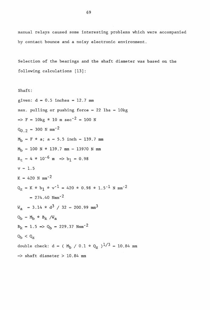
69
manual relays caused some interesting problems which were accompanied
by contact bounce and a noisy electronic environment.
Selection of the bearings and the shaft diameter was based on the
following calculations [13]:
Shaft:
given: d = 0.5 inches= 12.7 mm
max. pulling or pushing force= 22 lbs 10kg
=> F 10kg * 10 m sec- 2 = 100 N
Qo.2 300 N mm-2
Mb F * a; a= 5.5 inch= 139.7 mm
Mb 100 N * 139.7 mm= 13970 N mm
Rt 4 * 10- 6 m =>bl= 0.98
V = 1.5
K = 420 N mm-2
Q2 = K * b1 * v- 1 420 * 0.98 * 1.5- 1 N mm-2
= 274.40 Nmm-2
Wa = 3.14 * d 3 / 32 200.99 mm3
Qb Mb* Bk /Wa
Bk 1.5 => Qb = 229.37 Nmm-2
Qb < Qz
double check: d = (Mb/ 0.1 * Q2 ) 1/ 3
=> shaft diameter> 10.84 mm
10.84 mm

70
a distance between load and center
shaft diameter
V
peak load
fatigue strength under repeated bending stress
moment of flexion
surface roughness
= safety factor
bending stress
proof limit
safety load
section modulus
stress concentration factor
The constant torque T [13], required to turn a shaft with inertia Ix
(ft - lb - sec) from rest through an angel A (in degrees) in time t
(sec) is:
T 0.035 *Ix* D * t- 2
A 90°
t 2.0 sec.
Ix= 0.00388 * W * d2
Shaft: d = 12.7 mm
1 152.4 mm
0.042 ft
V d2 * 3.14 * 1/ 4 = 19305.56 mm3 = 19.305 cm3
W e * V = 7.89 * 10- 3 * 19.305 cm3 * kg cm- 3
0.15 kg= 0.34 lb

71
=> Ixl = 0.00388 * 0.34 * (0.042) 2 lb - ft - sec2
= 2.3 * 10- 6 lb - ft - sec 2
Table: d = 304.8 mm= 1.0 ft
1 12.7 mm
V 926.67 cm3
W = e * V = 2.7 * 10- 3 * 926.67 cm3 * kg cm-3
2.5 kg= 5.56 lb
Ix2 = 2.2 * 10- 3 lb - ft - sec 2
Grippers: Since the grippers are located around the table's inside
edge, their inertia can be assumed to be equal to a thick-walled
cylinder with inside diameter d = 0.42 ft and outside diameter D =
1.083 ft.
d = 0.42 ft
D = 1.083 ft
Gripper weight = 4 lb=> 16 lb for all 4 grippers
Ix 3 = 0.00388 * w * (d 2 + n2)
0.00388 * 16 * ((.42) 2 + (1.083) 2 )
8.36 * 10- 2 lb - ft - sec 2
Summation of all Ix's:
Ix 0.106 lb - ft - sec 2

T
72
0.035 * 0.106 * 90 * 2 lb ft sec 2 * sec- 2
0.0835 ft lb
16.03 oz inch
= constant torque
Ix inertia
d smaller diameter
D larger diameter
1 length
w weight
V volume
t time in which the table has to turn 90°
A Angle to be turned
The above calculations indicate that a stepping motor with a minimum
static torque capacity of 16 oz-inch is required to turn the table
equipped with 4 grippers 90 degrees within 2 seconds. A "Slo Syn"
stepping motor with 45 oz-inch static torque capacity was chosen to
satisfy the torque and design requirements. The torque capacity
requirement was more than fulfilled, so that a subsequent
implementation of heavy end of arm effectors would be permitted. The
turn table location within the workcell was selected to be as space
efficient as possible so as to provide a maximum of safety for man and
machine. In an earlier stage of this study, it was planned to locate
the carousel exactly at the home position to allow for good operator
access and space efficiency. Since the robot always must move to the

73
home position before a new program or cycle can be initiated, the
carousel was found to be an obstruction when long grippers were in
use. The final carousel station assures a minimal possibility of
collision, thus avoiding gripper and/or carousel damage. Additionally
it is described to withdraw or replace end effectors by using linear
motion to and from the desired holster.

74
Mounting Plate Lower Body Nut
Limit Switch
Upper Body
Face Plate Vacuum Gripper
Name Date Scale: 1 :1 Work
..... ch_eck-+----+------1 Figure 4.6 ~P.losion Drawing --

Chapter V
SYSTEM TESTING AND DEMONSTRATION
A series of tests was conducted to evaluate the performance and
reliability of the software and hardware systems. During the
implementation stage, certain testing procedures were carried out to
isolate potential problem areas. The test procedures were similar to
the procedures reported by Vranish [20].
5.1 Performance Testing
The quick change adapters were coupled manually, and the locking
sequence was simulated by actuating the locking cylinder. It was
found that of 50 trials, only 3 were completed satisfactorily. The
locking mechanism was dismantled and each component was tested
individually. All parts satisfied the demanding requirements fully,
so that the extremely high rate of failure had to be related to the
assembly process only. Additional examinations proved that the
adapters' bottle-neck was caused by the cylinder's highly concentric
tolerance. The problem was solved by placing an "0-Ring" between
quick change adapter and cylinder shoulder to compensate for the
concentric tolerance. The testing sequence as mentioned above was
reconducted, which yielded a continuous, fault free performance.
During the second testing phase, the manual coupling process was
75

76
replaced by an automatic mating sequence. The lower quick change body
was placed into the carousel manually, the turn table was fastened so
as to avoid uncontrolled motion, and the robot was taught the correct
pick up points in the teach mode. The pick up coordinates were down
loaded to the test software which moved the robot to mating depth,
actuated the locking cylinder and afforded the operator sufficient
time to determine if both adapters were coupled correctly or not.
After 15 seconds, the locking cylinder was deactuated, and the
unlocking cylinder was actuated and deactuated again.
After an additional 15 seconds, the end of arm was moved in positive Z
direction and the cycle was started again. All 50 cycles were
completed fault free and without any loss of reliability. Then, the
pick up coordinates were purposely modified in the software to
evaluate the system's compliance to pick up location errors. The
result of this testing phase was that even a rotational inaccuracy of
5 degrees and a displacement of+/- 0.2 inches in X and Y direction
were tolerated without any negative impact on the coupling process.
Plus and minus tolerances in Z direction have a completely different
influence on the system's performance. While plus tolerances (the
mating depth is not reached fully) can only be permitted within the
range of 0.003 inches, the system is much less sensitive for minus
tolerances. The turn table shaft diameter was chosen to be 1/4 inch,
so that the bending moment produced is strong enough to compensate
minus tolerances in Z direction up to 1/4 inch, even though the

77
robot's pushing capacity is limited to 22 lbs.
The fluid connectors were not tested separately, but no leakage was
ascertained during their use. Rotational and axial tolerances were
not evaluated because of the lack of high precision measurement
equipment. However, they were not found to be of significant
importance.
An AML/E program was written to test the stepping motor performance
when it received pulses from the controller output port. The software
was set up to turn the table to the home position, to read the
position switch status, and, depending on the value ( 1 or 0 for
closed or open switch respectively), generate further pulses or
interrupt the cycle for 10 seconds. After 10 seconds, 50 pulses were
transmitted to turn the table 90 degrees. BRANCH statements were used
to create an infinite loop, so that the performances in a 4 hour
non-stop turning cycle could be evaluated. An interesting problem was
discovered during the early implementation phase. Even though the
software generated the correct number of pulses, and stepping motor
and stepper drive card had been separately tested and proven to be
fault free, the carousel turned clockwise or counter-clockwise, in an
uncontrolled manner, thereby rendering an unacceptable performance.
An investigation of each of the system's components revealed that the
problem had not been caused by the stepping motor, the stepper drive
card, or any of the electrical contacts.

78
WRITEO and DELAY statements were used to create the pulses to be sent
to the stepper drive card from the controller output port. The
following sequence of commands were used to create one pulse:
WRITEO (DO 16, OFF);
DELAY (0.1);
WRITEO (DO 16, ON);
DELAY (0.1);
Open output port 16
Delay 0.1 seconds
Close output port 16
Delay 0.1 seconds
It was found that the established frequency of 5 Hz was not high
enough to drive the appropriate stepping motor. The achieved
frequency caused the undesirable system behavior that was being
experienced.
Since a delay of 0.1 seconds is the smallest possible value in AML/E,
5 Hz is the natural upper boundary for the system. Different lower
frequencies (2.5 Hz and 1 Hz) were tested but were found to be as
useless as 5 Hz. Correspondingly the goal was to establish a system
with more than 5 Hz. The idea of implementing a programmable
controller or a micro processor to drive the motor was dismissed to
keep the system as straightforward as possible. Further evaluations
proved that the mechanical controller output relay caused some
additional problems with its contact bounce.
Redesigning the stepper drive card allowed the use of contact bounce
to create a pulse frequency of 10 Hz without any software changes.
The implementation of the contact bounce established a system

79
performance of complete reliability and made it twice as fast as its
original version with 5 Hz. The testing loop was initiated again,
and a fault free, four-hour, non-stop cycle was completed.
The last sequence of tests was set up to appraise the logical and
mechanical coordination between robot, quick change adapter, carousel
and software. The palletizing software was reduced to the basic
gripper change sequence:
1. The end of arm moves above the carousel.
2. The carousel turns to the home position and revolves an
additional 45 degrees to locate the heavy weight gripper.
3. The end of arm moves down to mating depth.
4. The adapters are locked.
5.
6.
7.
8.
9.
The
The
The
The
The
gripper is slid out of its holster.
gripper is parked again.
adapters are unlocked.
end of arm moves above the pickup location.
end of arm moves to a known position.
In an early testing phase, the software was set up so that the
carousel first located the gripper in the pickup position before the
robot moved over to adapt the gripper. In this configuration, it was
discovered that each time the end of arm moved, the carousel started
shaking, and turning, and failed to reach the required degree of
accuracy. Signals, sent by the controller to move the end of arm were

80
partially transmitted to the stepper control circuit creating a noisy
electrical environment. To avoid gripper displacement in the pickup
phase, the software was modified so that the end of arm was located
first, and then the carousel turned the appropriate number of steps.
One of the interesting determinations of this test sequence is that
end of arm Z moves do not create a noisy environment, i.e. they do not
affect the carousel performance or its accuracy in any way. So that a
fault free cycle is guaranteed, the final software package was
established to locate the appropriate gripper in the pickup position
after all end of arm moves have been completed, even though the
gripper holster might already have been in the correct position. Two
hundred fault free gripper change and pickup cycles (described above)
proved the system to be reliable and advanced enough to satisfy
industrial demanding requirements.

81
Table 5.1 Test Summary
Test Results
50 locking cycles 3 fault free
with manual coupling cycles
50 locking cycles with manual 50 fault free
coupling, after compensating cycles
the cylinder's tolerance
50 locking cycles with
automatic coupling
10 carousel positioning cycles
with 5 Hz pulse frequency
2 carousel positioning cycles
with 1 Hz pulse frequency
4 hours (48 cycles) carousel
positioning cycles with 10 Hz
pulse frequency
200 automatic gripper change
and pickup cycles
50 fault free
cycles
no satisfying
result
no satisfying
result
fault free
performance
fault free
performance

82
5.2 System Demonstration
The workcell was laid out to allow a high degree of efficiency in
terms of used space, speed, and safety for the machine and the
operator. The layout consists of the "7545 Manufacturing System" with
the center coordinates X = 0, Y = 0, Z = 0, a "Fischer Technik"
conveyor with pickup location coordinates X 400, Y = 400, Z = -162,
R = 0, a pallet (scale 1:5) with lower left corner coordinates X =
-244.0, Y = 300.0, Z = 20.0, R = 0, a quick change adapter mounted to
the robot wrist, a vacuum gripper mounted to the quick change, and a
carousel gripper storage with pickup coordinates X = -401.0, Y
318.3, Z = -214.6, R = 54,0. (See Figure 5.1). Since neither dunnage
nor a mechanical gripper were available, the demonstration was given
within the following system environment:
1. One special purpose vacuum gripper with limited intelligence.
2. One complete quick change mechanism with two adapters
(lower and upper body).
3. A "Fischer Technik" conveyor with limited intelligence.
4. A complete stepping motor-driven carousel with four gripper
holsters.
5. A 9.6 inches by 8.0 inches pallet.
6. Thirty wooden blocks, serving as substitutes for real boxes
with inch dimensions of 3.2 by 2.4 by 0.5 respectively weighing
0.2 lbs.

83
Name Date
Work
t--Che_ck-+----+----t Figure 5.1 Robot Work (ell

84
The quick change lower body with vacuum gripper was placed into the
low weight gripper holster manually, and the carousel was turned to an
arbitrary position. The robot was powered on, connected to the PC, in
automatic mode, returned to the home position, and placed on line.
The software user disk was put into the IBM PC's disk drive A and the
AML/E system disk into drive B. The PC was boot loaded causing the
autoexecutable file to start the user program. As soon as the
environment was specified by the operator, the AML/E program for the
optimal interlock pattern was generated, compiled and loaded to the
robot controller. The operator initiated the cycle by pressing the
APPLICATION I button and the START CYCLE button. The robot's end of
arm moved above the carousel, the carousel was turned to the proper
holster, the end of arm picked up the gripper, moved over to the
conveyor and grasped a waiting box. While the robot sat the box in
its appropriate place on the pallet, the conveyor brought the next box
into the pickup location, where it signaled its presence by pressing a
limit switch. The robot moved over to the conveyor, grasped the next
box, the conveyor was started again, and the box was placed on the
pallet. When the first layer had been completed, the whole sequence
was repeated with a pallet pattern, turned 180 degrees. The third and
final layer was stacked in a pattern identical to the first layer. As
soon as the pallet had been stacked to capacity, the operator
attention horn was sounded. After 30 seconds, the end of arm moved in
front of the carousel, the low weight gripper holster was located
correctly, and the gripper was slid into the holster. The unlocking
sequence was followed by a fast move back to the home position, where

85
the operation was stopped when the emergency button was pressed.
When two boxes with larger width dimensions were to be stacked side by
side, it frequently happened that the problem of overlap between these
two boxes occurs so that pasteboard shippers would have been damaged.
If, in a real application, boxes with significant tolerances must be
stacked, two possible solutions to the problem can be applied:
1. The input data must be identical to the largest possible box
dimension. This solution tolerates a relatively low pallet
utilization.
2. The stacking sequence must be modified, so that the boxes are slid
into the appropriate position on the pallet. This solution
tolerates some boxes being pushed aside sightly and the inside
pallet edges being overlapped.

Chapter VI
CONCLUSIONS AND RECOMMENDATIONS
The goal of linking material handling with flexible automation to
create a combination of off-line and on-line programming was achieved
and afterwards successfully implemented in a practical application. A
complex demonstration underlined system uniqueness. Although certain
aspects of this study have been examined by other researchers, there
has been no similar composite study established.
6.1 Critique and Extensions
The implemented interlock heuristic and the combined heuristic provide
a very high pallet utilization which exceeds the initially expected
results. A heuristic like the "Two Dimensional Cutting Stock
Problem Algorithm" [17] might have offered better solutions. Since
the software was set up in a modular fashion, alternatives could be
implemented later without changing the whole concept. Three
extensions within the palletizing framework could be subject to
further research in a succeeding project:
1. Implementation of bar code labels and reader.
2. Implementation of computer vision.
3. Providing multiple pallets.
86

87
The implementation of bar code labels and readers would make the
system even more independent of operator intervention. Boxes could be
labeled according to size and weight differently, and a bar code
reader, mounted to the conveyor, could read the information for the
current production batch. The bar code information could be
transformed to the PC, and the interactive program phase could be
handled automatically. The system described above would require
operator intervention only when problems arise and at the beginning or
the end of a shift. If on-line communication between bar code reader
and PC were to be established, the PC would have to be tied to the
system permanently. This is a disadvantage when compared to a system
in which the PC is only used in the first phase of the process.
If differently sized boxes were not produced in batch sizes, but
individually, production would have to be examined and sorted
beforehand. Shippers of equal size and weight would have to be
collected in buffer facilities and then sent into the system serial,
or computer vision or bar code readers would have to be coupled to
host computer communication. Each arriving box would have to be
handled separately. Both solutions are quite complex and changes in
production sequence should be considered so that a fundamental basis
for succeeding automation is established to reach high economic
justification. Computer vision could be used to determine the box
sizes as they are transported on the conveyor and to recognize the
precise pallet location. Even multiple pallets could be provided
inside the workcell to avoid idle time. Another useful extension

88
would also be the introduction of a conveyor system for the pallets so
that the operator would not have to enter the workcell at all.
The idea of using bar code labeling could also be employed to the
quick change and carousel system so that grippers would not always
have to be placed in the same holster. Since 10 Hz is the upper
frequency limit for robot controller generated pulses, a programmable
controller or even a microprocessor could improve the speed and system
performance significantly. The microprocessor or programmable
controller would be initiated by the robot controller. The pulses,
however, would be generated externally.
The quick change adapter's performance is satisfying and reliable. But
if the same locking mechanism were used, smaller and lighter system
design might be possible to make the quick change better applicable to
small assembly robots with very low pulling or pushing capacity. The
introduction of plastic as basic construction material, the use of
multiple small electrical connections instead of one large connector,
and an overall diameter reduction could cause significant improvement
in task fulfillment.
Microprocessor capabilities should be added to the quick change or to
the different grippers, to establish a system consisting of as few
approximations as possible. If grasping, pulling, pushing and tilting
forces could be measured and transformed to the robot controller, a
high degree of intelligence could be added to the system. Damage and

89
waste production could be recognized at an early stage or even be
avoided.
The extension of the overall concept to non-palletizing operations as
well as the linking to Artificial Intelligence could be considered. A
classic non-palletizing robot application area is the paint spraying
of fixed parts, especially in the automobile industry. If fixtures
wear out, and parts are not located correctly, a fault free paint
spraying process is no longer guaranteed. If parts to be sprayed are
of various shapes or sizes, a large number of programs would have to
be generated, compiled and loaded to the controller. If computer
vision could be introduced to such a process, parts would not have to
be fixed and ordered beforehand.
The spraying software could be generated dynamically, based on the
vision systems input data. The whole production program could be
recognized by the vision system. The problem of viewing only one
surface of the part and then generating a three dimensional control
program could be solved by introducing a kind of Expert System.
Complex data bases would have to be generated previously, however
economic justification could still be reached because of high and
frequently changing production rates. Coupling the CAD system to data
base generation would probably offer considerable support establishing
Expert Systems.

REFERENCES
1. Abair, D. "Modern Solution to Old Problems - Palletizing With Industrial Robots". Proceedings - 14th International Symposium on Industrial Robots, Robots 8 Volume I. (pp. 3.29-3.45), June 1984.
2. Automation Staff, "Palletizing and Unitizing: How Robots Stackup". Modern Materials Handling Vol.39, No.9,(pp. 59-62). September 7, 1984.
3. Crawford, K.R., Edwards R., Fisher A.V., and McCormick P.E., "Intelligent Interchangeable Robotic End-of-Arm Tooling". Proceedings Robots 8, Volume II (pp. 17.31-17.37), June 1984.
4. DE Meter E., Mertens P., "Communication Library", Unpublished term paper. IEOE Viriginia Polytechnic Institute and State University, Blacksburg, Virginia, July 1985.
5. Engelberger J, Robotics in Practice. Management and Applications of Industrial Robots. American Management Association, 1980 (Chapter 22).
6. Grab, E., "Robot Palletizing Center (RPG)". Proceedings - 14th International Symposium on Industrial Robots, 7th International Conference on Industrial Robot Technology. Volume I (pp. 287-296), 1984.
7. Haynes, D. 0., Material Handling Equipment, Clinton, Philadelphia, 1957.
8. Hinson R., "Study Analysis Utilizing Robots in Palletizing". Industrial Engineering, Vol.16, No.2., (pp. 21-24) February 1984,
9. IBM, A Manufacturing Language/Entry Version 4, User's Guide, New York, 1984.
10. Kehoe, E.J., "The Expanding Repertoire of Robotic End Effectors". Robotics Today, Vol.6, No.6, (pp. 35-36) December 1984.
11. Kulick, A., "Interlocking Pallet Pattern Simulation Program". Journal of Industrial Engineering. Vol.14, No.9, (pp. 22-24) September 1984.
12. Lentz,W.K., (1985). Design of Automatic Machinery. Van Nostrand Reinhold Company, New York. 1985, (Chapter 6.3.2).
90

91
13. Rolof, H., Matek, W., Maschinenelemente, Normung, Berechnnung, Gestaltung. 7th edition Vieweg Verlag, Nuernberg, Braunschweig, Reutlingen, Febuary 1976, (Chapter 9).
14. Seger, B., "Box Palletizing Carved out by Means of an Industrial Robot with Sophisticated Control System". Proceedings - 5th International Symposium on Industrial Robots, Volume II, (pp.557-564), September 1985.
15. Snyder, W. E., Industrial Robots, Computer Interfacing and Control, Prentice-Hall Inc. (pp. 300-313) Prentice-Hall Inc. Engewood, Cliffs, New Jersy 1985.
16. Stauffer, R.N., "Palletizing/Depalletizing: Robots Make it Easy". Robotics Today, Vo.16, No.1 (pp. 43-46) February 1984.
17. Steudel, H.J., "Generating Pallet Loading Patterns: a Special Case of the Two Dimensioanal Cutting Stock Problem". Journal of Management Science, Vol.25, No.10, (pp. 997-1004) October 1979.
18. Unimation, Inc. User's guide to VAL, Danbury, 1979.
19. Vasilash, G. S., "Increasing Production in Palletizing". Robotics Today. Vol.2, No.2, (p. 20), Fall 1980
20. Vranish, J.M., "Quick Change System for Robots. Proceedings Robots 8, Volume II, (pp. 17.74-17.97), June 1984.
21. Wright, A. J., "End Effector Technology and Programmed Automatic Exchange". Proceedings - 13th International Symposium on Industrial Robots, Robots 7, Volume II, (pp. 18.1-18.18), April 1983.

92
APPENDIX A
INTERLOCK PROGRAM

93
C INTERLOCKPROGRAM INTEGER BLACK,BLUE,GREEN,CYAN,RED,MAGENTA,YELLOW INTEGER WHITE,BBLACK,BBLUE,BGREEN,BCYAN,BRED INTEGER BMAGENTA,BYELLOW,BWHITE,BLINK,HIGHINT INTEGER X,J,B,Al,Cl,C2,Y,Zl,P,XP1,XP,XP3,XP4,XP5,TOT,A,Z,Xl INTEGER X2,X3,X4,X5,X6,K,A2,A3,A4,A5,M,I,N,A6,A7,A8,A9,E INTEGER NN,IIJ,KK,JK,IJ,III,JJJ,LENGT,ATTRIB,PPRl,PPR2,PPR3 INTEGER PPR4,Nl,N2,N3,N4,WEIGHT,NlR,N2R,N3R,N4R,WW REAL LENGTH, WIDTH, HEIGHT, UTI, L, H, W,X7,XK,XL,LEFTX,LEFTY REAL RIGHTX,RIGHTY,UPRX,UPRY,PICKX,PICKY,PICKZ,PICKR,HFRAME REAL XBOX,XBOX1,YBOX,YBOX1,Pl,P2,LO,WO,HO,XBOX2,XBOX3 REAL ZMOVE,ZPICK,LLX1,LLX2,LLX3,LLX4,LLY1,LLY2,LLY3,LLY4 REAL LRX1,LRX2,LRX3,LRX4,LRY1,LRY2,LRY3,LRY4,URX1,URX2,URX3,URX4 REAL PICKX1,PICKY1,PT(l00),Xll,X22,X33,X44,DUZ(20),INTERX,INTERY REAL INTERZ,INTERR,SEMIX,SEMIY,SEMIZ,SEMIR,MATE,CARLX REAL CARLY,CARLZ,CARLR DOUBLE PRECISION Ml(20,20) CHARACTER*70 STR1,STR6 CHARACTER STR2(70),STR3(70),STR7(70),STR8(70) EQUIVALENCE (STR1,STR2(1)) EQUIVALENCE (STR6,STR7(1)) DATA BLACK,BLUE,GREEN,CYAN,RED,MAGENTA,YELLOW /0,1,2,3,4,5,6/ DATA WHITE,BBLACK,BBLUE,BGREEN,BCYAN,BRED /7,0,16,32,48,64/ DATA BMAGENTA,BYELLOW,BWHITE,BLINK,HINGHINT /80,96,112,128,8/ 1=244.00 W=203.20 LEFTX=-244. LEFTY=300.00 RIGHTX=O.O RIGHTY=300.00 UPRX=O.O UPRY=503.20 HFRAME=20.0 PICKX=400.00 PICKY=400.00 PICKZ=-162.00 PICKR=O.O INTERX=-401.0 INTERY=-318.3 INTERZ=O.O INTERR=54.0 SEMIX=-401.0 SEMIY=-200.0 SEMIZ=-212.0 SEMIR=54.0 MATE=-214.6 CARLX=-401.0 CARLY=-318.3 CARLZ=-212.0 CARLR=54.0 X=O

E=O J=O XK.=0.0 XL=O.O Xl=O X2=0 X3=0 X4=0 X5=0 X6=0 X7=0.0 DO 1 K=l,20 DO 1 Ll=l,20 Ml(K,Ll)=O
1 CONTINUE ATTRIB=WHITE + BBLUE CALL CLS(ATTRIB)
94
CALL PRINT(l0,15,'THIS PROGRAM CALCULATES AN INTERLOCK PATTERN' *,44)
GOT03 ********************************************************************** C QUERY USER FOR INPUT DATA ********************************************************************** 2 CALL PRINT(l0,19,'PLEASE MAKE SURE THAT LENGTH GREATER WIDTH' ,42) 3 CALL PRINT(l3,21,'TYPE 1 IF YOU WANT THE INPUT IN INCHES' ,38) *'·k********************************************************"k*·k*"k******* C DETERMINE WHETHER THE USER PREFERS TO WORK IN INCHES OR MM **********************************************************************
CALL PRINT(lS,22,'TYPE O IF YOU WANT THE INPUT IN MM' ,34) CALL PRINT(l7,30,'ENTER OPTION ==>' ,17)
CALL INKEY(INCH,MM) IF(INCH.EQ.49)THEN CALL CLS(ATTRIB) CALL PRINT(l0,22,'PLEASE GIVE WIDTH OF SHIPPER IN INCH' ,36) CALL PRINT(l2,30,'ENTER OPTION ==>' ,17) READ (*,*)WIDTH CALL CLS(ATTRIB) CALL PRINT(l0,21,'PLEASE GIVE LENGTH OF SHIPPER IN INCH' ,37) CALL PRINT(l2,30,'ENTER OPTION -->' ,17) READ (*,*)LENGTH CALL CLS(ATTRIB) CALL PRINT(l0,21,'PLEASE GIVE HEIGTH OF SHIPPER IN INCH' ,37) CALL PRINT(l2,30,'ENTER OPTION ==>' ,17) READ (*,*)HEIGHT CALL CLS(ATTRIB) CALL PRINT(l0,20, 'PLEASE GIVE MAX. HEIGHT OF PALLET IN INCH' ,41) CALL PRINT(l2,30, 'ENTER OPTION ==>' ,17) READ(*,*)H CALL CLS(ATTRIB) CALL PRINT(l0,20, 'TYPE 1 IF BOX WEIGHT IS IN THE RANGE OF' ,39) CALL PRINT(ll,30,'0 - 5 lb.' ,9)

95
CALL PRINT(l5,20,'TYPE O IF BOX WEIGHT IS IN THE RANGE OF' ,39) CALL PRINT(16,30,'5 - 10 lb.' ,10) CALL PRINT(l8,30,'ENTER OPTION ==>' ,17) READ(*,*)WEIGHT CALL CLS(ATTRIB) CALL PRINT(l0,20,'TYPE 1 IF THE PALLET SHALL BE STACKED' ,37) CALL PRINT(12,25, 'WITH DUNNAGE, ELSE TYPE 0' ,25) CALL PRINT(l4,30,'ENTER OPTION ==>' ,17) READ (*,*)DUNYES IF(DUNYES.EQ.l)THEN CALL CLS(ATTRIB) CALL PRINT(l0,20,'PLEASE GIVE THICKNESS OF DUNNAGE IN INCH' ,40) CALL PRINT(12,30,'ENTER OPTION =>' ,17) READ(*,*)THICK ENDIF
.. k****************************************************************··k~k**** C TRANSFORMING INCHES INTO MM ***********************************************************************
WIDTH=WIDTH*25.4 LENGTH=LENGTH*25.4 HEIGHT=HEIGHT*25.4 H=H*25.4 THICK=THICK*25.4 ELSE CALL CLS(ATTRIB) CALL PRINT(l0,18,'PLEASE GIVE WIDTH OF SHIPPER IN MM' ,34) CALL PRINT(12,30,'ENTER OPTION ==>' ,17) READ (*,*)WIDTH CALL CLS(ATTRIB) CALL PRINT(l0,19,'PLEASE GIVE LENGTH OF SHIPPER IN MM' ,35) CALL PRINT(l2,30,'ENTER OPTION ==>' ,17) READ(*,*)LENGTH CALL CLS(ATTRIB) CALL PRINT(l0,19,'PLEASE GIVE HEIGTH OF SHIPPER IN MM' ,35) CALL PRINT(12,30,'ENTER OPTION ==>' ,17) READ (*,*)HEIGHT CALL CLS(ATTRIB) CALL PRINT(l0,19,'PLEASE GIVE HEIGTH OF SHIPPER IN MM' ,35) CALL PRINT(12,30,'ENTER OPTION ==>' ,17) READ(*,*)H CALL CLS(ATTRIB) CALL PRINT(l0,20,'PLEASE GIVE MAX. HEIGHT OF PALLET IN MM' ,39) CALL PRINT(l2,30,'ENTER OPTION ==>' ,17) CALL CLS(ATTRIB) CALL PRINT(l0,20,'TYPE 1 IF BOX WEIGHT IS IN THE RANGE OF' ,39) CALL PRINT(ll,30,'0 - 5 lb.' ,9) CALL PRINT(l5,20, 'TYPE O IF BOX WEIGHT IS IN THE RANGE OF' ,39) CALL PRINT(16,30,'5 - 10 lb.' ,10) CALL PRINT(18,30,'ENTER OPTION ==>' ,17) READ(*,*)WEIGHT CALL CLS(ATTRIB)

96
CALL PRINT(l0,20,'TYPE 1 IF THE PALLET SHALL BE STACKED' ,37) CALL PRINT(12,25,'WITH DUNNAGE, ELSE TYPE 0' ,25) CALL PRINT(l4,30,'ENTER OPTION ==>' ,17) READ (*,*)DUNYES IF(DUNYES.EQ.l)THEN CALL CLS(ATTRIB) CALL PRINT(l0,20,'PLEASE GIVE THICKNESS OF DUNNAGE IN MM' ,37) CALL PRINT(12,30,'ENTER OPTION ==>' ,17) READ(*,*)THICK ENDIF ENDIF IF(WIDTH.GT.LENGTH)GOTO 2 IF(W.GT.L)GOTO 2
*"'k****************************************"'k********"'k·k*********·-k***·k***·-k C INTERLOCKING ALOGRITHM BEGINNS *************************************************************"1'c****·k*'k*"k
LO=L WO=W B=INT(H/HEIGHT)
4 X=X+l Al=INT(WO/LENGTH) IF(Al.GT.20)A1=20 Cl=INT(LO/WIDTH) C2=INT(LO/LENGTH) DO 5 A=Al,1,-1 Ml(A,J+l)=X Ml(A,J+2)=A Ml(A,J+3)=B Ml(A,J+7)=B Ml(A,J+4)=Cl Ml(A,J+S)=A*B*Cl Ml(A,J+8)=C2 Ml(A,J+6)=INT(((WO-(REAL(A)*LENGTH))/WIDTH)+.05) Ml(A,J+9)=Ml(A,J+6)*B*C2 IF(Ml(A,J+9).EQ.O)Ml(A,J+5)=0 IF(Ml(A,J+5).EQ.O)Ml(A,J+9)=0
5 CONTINUE IF(Al.NE.O)GOT06 CALL CLS(ATTRIB) CALL PRINT(l0,20,'THERE ARE NO POSSIBLE INTERLOCK PATTERN' ,39) GOTO 170
6 IF(X.EQ.l)THEN J=9 LO=WO WO=LO GOT04 ENDIF DO 7 X=l,20 Ml(X,19)=Ml(X,5)+Ml(X,9) Ml(X,20)=Ml(X,14)+Ml(X,18)
7 CONTINUE

DO 9 2=1,30 Y=l 21=0 A=Ml(l,19) B=Ml(l,20) IF(A.LT.B)THEN 21=9 A=B ENDIF DO 8 X=2,20 IF(Ml(X,19).GT.A)THEN A=Ml (X, 19) Y=X 21=0 ENDIF IF(Ml(X,20).GT.A)THEN 21=9 Y=X A=Ml(X,20) ENDIF
8 CONTINUE P=Ml(Y,21+1) XPl=Ml(Y,21+2) XP2=Ml(Y,21+4) XP3=Ml(Y,21+6)
97
XP4=Ml (Y, 21 +8) XP5=Ml(Y,21+2)*Ml(Y,21+4)+(Ml(Y,21+6)*Ml(Y,21+8)) Pl=(Ml(Y,21+2)*Ml(Y,21+4))+(Ml(Y,21+6)*Ml(Y,21+8)) P2=LENGTH*WIDTH*HEIGHT*REAL(Ml(Y,21+3)*100) XL=(XPl*XP2+XP3*XP4) IF(XL.GT.XK)THEN XK=(XPl*XP2+XP3*XP4) Xl=XPl X2=XP2 X3=XP3 X4=XP4 X5=XP5 X6=((Xl*X2+X3*X4)*INT((H/HEIGHT)+.5)) X7=((Xl*X2+X3*X4)/(L*W/(WIDTH*LENGTH)))*l00.00 ENDIF IF(21.EQ.O)Ml(Y,19)=0 IF(21.EQ.9)Ml(Y,20)=0
9 CONTINUE '"k"'k*****************************************************·k*******·-k·k*··k***"k C PRINTING THE VALUES OF: Xl,X2,X3,X4,UTILI2ATION, THE# OF C SHIPPERS PER LAYER, AND THE TOTAL# OF SHIPPERS ON THE PALLET. ·k************************************************";'c***·k*i(****··k*1<***·k1'(***
CALL CLS(ATTRIB) WRITE(*,lO)Xl
10 FORMAT(lX, 'Xl=', lX, I7) WRITE(*,ll)X2

11 FORMAT(lX,'X2=' ,1X,I7) WRITE(*,12)X3
12 FORMAT(lX, 'X3=', lX, 17) WRITE(*,l3)X4
13 FORMAT(lX, 'X4=', lX, 17) WRITE(*,14)X5
98
14 FORMAT(lX,'TOTAL NUMBER OF SHIPPER PER LAYER=' ,1X,I7) WRITE(*,15)X6
15 FORMAT(lX, 'TOTAL NUMBER OF SHIPPER ON PALLET=' ,1X,I7) WRITE(*,16)X7
16 FORMAT(lX,'PALLET UTILIZATION=' ,1X,F5.2,1X,'PERCENT') "1(·k·k********************************* .. k************************·k*****i~*·k* C DETERMIN THE Z VALUE OF EVERY LAYER ON THE PALLET ********************************************··k***********************··k*·k
ZMOVE=-25O+(HFRAME+HEIGHT) IF(Xl.EQ. l)THEN
*~'r:*~'(******************''r:************************''r:*****************~'r:**''r:~'(* C CREATING AN ARTIFICIAL EXTRA ROW IF INITIAL PALLET CONSISTS OF C ONLY ONE ROW ***********************************************************************
Xll=2 ELSE Xll=Xl ENDIF IF(X2.EQ.l)THEN X22=2 ELSE X22=X2 ENDIF IF(X3.EQ.l)THEN X33=2 ELSE X33=X3 ENDIF IF(X4.EQ.l)THEN X44=2 ELSE X44=X4 ENDIF
***·k**********************************************"'(******''k***"'k******'·k*"'k C DETERMINING THE LOWER LEFT, LOWER RIGHT, UPPER RIGHT CORNER C SHIPPER CENTER POINTS FOR ALL 4 POSSIBLE PALLET CONFIGURATIONS *"'k·k*******"'k************************************ .. k*****************'"k*****
LLXl=-64.O+LENGTH/2 LLY1=29O.+WIDTH/2 LRX1=18O-LENGTH/2 LRYl=LLYl URXl=LRXl URYl=LRYl+(X3-l)*WIDTH Nl=X33*X44 NlR=X3*X4

PPR1=X4 LLX2=-64.O+WIDTH/2 LLY2=URY1+(LENGTH/2)+(WIDTH/2)+5.5 LRX2=18O-(WIDTH/2)+1O. LRY2=LLY2 URX2=LRX2 URY2=LRY2+(Xl-l)*LENGTH+9.O N2=Xll*X22 N2R=Xl*X2 PPR2=X2
LLX3=LLX2 LLY3=29O.+LENGTH/2+5.5 LRX3=LRX2 LRY3=LLY3 URX3=LRX3 URY3=LRY3+(Xl-l)*LENGTH N3=Xll*X22 N3R=Xl*X2 PPR3=X2
LLX4=LLX1 LLY4=URY3+(LENGTH/2)+(WIDTH/2) LRX4=LRX1 LRY4=LLY4 URX4=LRX4 URY4=LLY4+(X3-l)*WIDTH N4=X33*X44 N4R=X3*X4 PPR4=X4
99
*"k********************************************************************"k C OPENING THE AML FILE FOR CREATING THE CONTROL PROGRAM ***********************************************************************
OPEN(3,FILE='NEW.AML' ,STATUS='NEW') ************************"''c******·k*************************************** C DETERMINE THE# OF LAYERS ****************************************************************** .. k*"J'<**
LAYER=INT(H/HEIGHT+.5) *~'<**********************************************"k***********-,'<**''k**-,'c**** C IF DUNNAGE IS REQUESTED, ADD HEIGHT OF DUNNAGE TO Z VALUE FOR C EACH LAYER ***********************************************************************
IF(DUNYES.EQ.l)THEN DUNN=-1 DO 18 I=l,LAYER DUNN=DUNN+l PT(I)=I*HEIGHT-25O.+THICK*DUNN
18 CONTINUE ELSE DO 19 I=l,LAYER PT(I)=I*HEIGHT-25O.+HFRAME

19 CONTINUE ENDIF
100
*******************************************************************~'(*~'(* C PUTTING Z VALUES INTO A STRING TO ZAP OF THE BLANKS * .. k*******************************************************"'k***"k****-,'r:**··k*
DO 30 I=l,LAYER WRITE(STRl,20)1,PT(I)
20 FORMAT(lX,'Z ',13,' :' ,3X,'NEW' ,1X,F7.2' ;') IF(STR2(3).NE.' ')GOTO 26 STR3(1)=STR2(1) STR3(2)=STR2(2) 111=3 DO 21 II =3,12 IF(STR2(II).NE.' ')GOTO 22
21 CONTINUE 22 CONTINUE
DO 23 JJ=II, 60 STR3(III)=STR2(JJ) IF(STR2(JJ).EQ.';')GOTO 24 III=III+l
23 CONTINUE 24 CONTINUE
WRITE(3,25)(STR3(KK),KK=l,III) 25 FORMAT(60Al)
GOT029 26 CONTINUE
DO 27 III=l,60 IF(STR2(III).EQ.' ;')GOTO 28
27 CONTINUE 28 CONTINUE
WRITE(3,25)(STR2(KK),KK=l,III) 29 CONTINUE 30 CONTINUE **************************************************"k*******''k*********''t:** C WRITE GLOBAL PALLET CONST. INTO AML FILE ***********************************************************************
WRITE(3,31)LLX1,LLY1 31 FORMAT(lX,'LLl: NEW PT(' ,F7.2,' ,' ,F7.2,' ,0,90);')
WRITE(3,32)LRX1,LRY1 32 FORMAT(lX,'LRl: NEW PT(' ,F7.2,' ,' ,F7.2,' ,0,90);')
WRITE(3,33)URX1,URY1 33 FORMAT(lX,'URl: NEW PT(' ,F7.2,' ,' ,F7.2,' ,0,90);')
WRITE(3,34)Nl 34 FORMAT(lX,'Nl: NEW' ,13,' ;')
WRITE(3,35)N1R 35 FORMAT(lX,'NlREAL: NEW' ,13,' ;')
WRITE(3,36)PPR1 36 FORMAT(lX, 'PPRl: NEW' ,13,' ;')
WRITE(3,37)LLX2,LLY2 37 FORMAT(1X,'LL2: NEW PT(' ,F7.2,' ,' ,F7.2,' ,0,0);')
WRITE(3,38)LRX2,LRY2

101
38 FORMAT(lX,'LR.2: NEW PT(' ,F7.2,' ,' ,F7.2,' ,0,0);') WRITE(3,39)URX2,URY2
39 FORMAT(lX,'UR2: NEW PT(' ,F7.2,' ,' ,F7.2,' ,0,0);') WRITE(3,40)N2R
40 FORMAT(1X,'N2REAL: NEW' ,13,' ;') WRITE(3,41)N2
41 FORMAT(1X,'N2: NEW' ,13,' ;') WRITE(3,42)PPR2
42 FORMAT(1X,'PPR2: NEW' ,13,' ;')
WRITE(3,43)LLX3,LLY3 43 FORMAT(1X,'LL3: NEW PT(' ,F7.2,' ,' ,F7.2,' ,0,0);')
WRITE(3,44)LRX3,LRY3 44 FORMAT(lX,'LR.3: NEW PT(' ,F7.2,' ,' ,F7.2,' ,0,0);')
WRITE(3,45)URX3,URY3 45 FORMAT(lX, 'UR3: NEW PT(' ,F7.2,' ,' ,F7.2,' ,0,0); ')
WRITE(3,46)N3 46 FORMAT(1X,'N3: NEW' ,13,' ;')
WRITE(3,47)N3R 47 FORMAT(1X,'N3REAL: NEW' ,13,' ;')
WRITE(3,48)PPR3 48 FORMAT(lX,'PPR3: NEW' ,13,' ;')
WRITE(3,49)LLX4,LLY4 49 FORMAT(1X,'LL4: NEW PT(' ,F7.2, ',' ,F7.2,' ,0,90);')
WRITE(3,50)LRX4,LRY4 50 FORMAT(lX, 'LR.4: NEW PT(' ,F7.2,' ,' ,F7.2, ',0,90); ')
WRITE(3,51)URX4,URY4 51 FORMAT(1X,'UR4: NEW PT(' ,F7.2,' ,' ,F7.2,' ,0,90);')
WRITE(3,53)N4 WRITE(3,52)N4R
52 FORMAT(1X,'N4REAL: NEW' ,13, ';') 53 FORMAT(1X,'N4: NEW' ,13,' ;')
WRITE(3,54)PPR4 54 FORMAT(lX,'PPR4: NEW' ,13,' ;')
WRITE(3,55)LAYER 55 FORMAT(lX,'LAYER: NEW' ,13,' ;') *********************************************************************** C DECLARATION OF DI/DO POINTS ***********************************************************************
WRITE(3,56) 56 FORMAT(lX,'OPER_ATTNHORNl: NEW 10;')
WRITE(3,57) 57 FORMAT(lX,'OFF:NEW 0;' ,/,'OPER_RETRY: NEW 1;' ,/, 'ON:NEW 1;' ,/
*'OPER_ATTNHORN: NEW 11;' ,/,'PORT: NEW 5;')
*********************************************************************** C WRITING GLOBAL VARIABLES INTO AML FILE ***********************************************************************

102
WRITE(3,58) 58 FORMAT(lX, 'PITT: STATIC COUNTER;',/, 'TURN :STATIC COUNTER;')
WRITE(3,59) 59 FORMAT(lX,'SAMPLEl: STATIC PALLET(LLl,LRl,URl,PPRl,Nl);')
WRITE(3,60) 60 FORMAT(lX,'SAMPLE2: STATIC PALLET(LL2,LR2,UR2,PPR2,N2);')
WRITE(3,61) 61 FORMAT(lX,'SAMPLE3: STATIC PALLET(LL3,LR3,UR3,PPR3,N3); ')
WRITE(3,62) 62 FORMAT(1X,'SAMPLE4: STATIC PALLET(LL4,LR4,UR4,PPR4,N4);')
WRITE(3,63)INTERX,INTERY,INTERZ,INTERR,SEMIX,SEMIY, *SEMIZ,SEMIR,MATE,CARLX,CARLY,CARLZ,CARLR
63 FORMAT(lX,'INTER:NEW PT(' ,F7.2,' ,' ,F7.2,' ,' ,F7.2,',' ,F7.2,');' ,/ *'SEMI:NEW PT(',F7.2,' ,',F7.2,' ,',F7.2,',' ,F7.2,');' ,/ *'RESTART:NEW 5;' ,/,'MATE: NEW' ,F7.2, ';' ,/,'ZYLINDERl: NEW 1;' ,/ *'ZYLINDER2: NEW 5;' ,/,'STEP: NEW 16;' ,/,'HOMEl: NEW 9;' ,/ *'CAROUSSEL: NEW PT(' ,F7.2,',' ,F7.2,' ,' ,F7.2,' ,' ,F7.2,');' ,/ *'PALLET_CENTER: NEW PT(0,0,0,0);' ,/ *'DUNN_PICKUP: NEW PT(0,0,0,0);')
WRITE(3,64)PICKZ 64 FORMAT(lX,'PICKZ: NEW' ,F7.2,' ;')
WRITE(3,65)PICKX,PICKY 65 FORMAT(lX,'PICKY: NEW PT(' ,F7.2,' ,' ,F7.2,' ,0,0 );') **··k .. k************************* ... k********************************·k***''<*·-k*·k C HEIGHT OF DUNNAGE PILE AFTER EACH IAYER *,,'<************''(****************************************·k****;'<**********
DO 67 I=l,IAYER DUZ(I)=PT(I)+THICK WRITE(3,66)I,DUZ(I)
66 FORMAT(lX,'DUZ' ,Il,' :NEW' ,F7.2,' ;') 67 CONTINUE *********************************************************************** C START OF THE MAIN SUBROUTINE ***'''**************************************************'"***********"k**"k* WRITE(3,68) 68 FORMAT(lX,'MAINPROG:SUBR;') *****************************************************************"k*-,'<**''< C SET HOME SUBROUTINE TURNS THE CROUSSEL TO KNOWN POSITION **"k*****''<************************************************·k*****''<**·-k***·k
WRITE(3,69) 69 FORMAT(lX,'SET_HOME:SUBR;')
WRITE(3,70) 70 FORMAT(lX,'LOOP:WRITEO(STEP,OFF);DEIAY(O.l);WRITEO(STEP,ON);' ,/
*'DEIAY(O.l);TESTI(HOMEl,ON,DONE);' ,/ *'BRANCH(LOOP);' ,/,'DONE:BREAKPOINT;' ,/,'END;')
*******************************************·k**°"'<**"k********** ... k****"k*·k*·k* C ROTATE SUBROUTINE ROTATES THE CAROUSSEL TO THE REQUESTED DEGREE **************************************************************·k**··k·k****
WRITE(3,71) 71 FORMAT(lX,'ROTATE:SUBR(DEGREE);')
WRITE(3,72)

103
72 FORMAT(lX,'SETC(TURN,l);LOOP:WRITEO(STEP,OFF);DELAY(O.l);' ,/ *'WRITEO(STEP,ON);DELAY(O.l);' ,/ *'TESTC(TURN,DEGREE,DONE);' ,/,'INCR(TURN);BRANCH(LOOP);' ,/ ~·, I DONE: BREAKPOINT; I '/' I END; I)
IF(WEIGHT.EQ.l)THEN ·k*·k***************************************************************"k*·k* .. k C IF SHIPPER WEIGHT IS IN THE RANGE OF O - 5 LB, THE ROBOT WILL C PICK UP THE SMALL VACUUM GRIPPER
WRITE(3,73) 73 FORMAT(lX,'INTERCHANGE_BEGIN_REG:SUBR;')
WRITE(3,74) 74 FORMAT(lX,'PMOVE(INTER);SET_HOME;PAYLOAD(ll);ZONE(l);' ,/
*'ZMOVE(MATE);WRITEO(ZYLINDER1,0N);DELAY(2);PMOVE(SEMI);' ,/ *'WRITEO(l5,0N);ZONE(O);PAYLOAD(O);' ,/ *'ZMOVE(O);WRITEO(l5,0N);END;')
ELSE *********************************************************************** C IF SHIPPER WEIGHT IS IN THE RANGE OF 5 - 10 LB, THE ROBOT WILL C PICK UP THE BIG VACUUM GRIPPER *"1'c*****************************************************************''t:**'''
WRITE(3,75) 75 FORMAT(lX,'INTERCHANGE_BEGIN_HEAVY:SUBR;')
WRITE(3,76) 76 FORMAT(lX,'PMOVE(INTER);PAYLOAD(ll);SET_HOME;ROTATE(25);' ,/
*'ZONE(l);ZMOVE(MATE);WRITEO(ZYLINDERl,ON);ZONE(O);' ,/ *'DELAY(2);PMOVE(SEMI);LINEAR(O);' ,/,'WRITEO(lS,ON);' ,/ *'PAYLOAD(O);ZMOVE(O);WRITEO(l5,0N);' ,/,'END;')
ENDIF IF(DUNYES.EQ.l.AND.WEIGHT.EQ.l)THEN
********************************************************** .. k**********"k* C DUNN GRIPPER ROTATE SUBROUTINE ROTATES THE CAROUSSEL TO ENABLE - -C THE ROBOT TO PICK UP THE DUNNAGE GRIPPER ******************************************')'t:*************************··k**
WRITE(3,77) 77 FORMAT(lX,'DUNN_GRIPPER_ROTATE:SUBR(PLACES); ')
WRITE(3,78) 78 FORMAT(lX,'PMOVE(SEMI);LINEAR(l);SET_HOME;PMOVE(CAROUSSEL);' ,/
*'WRITEO(ZYLINDER1,0FF);DELAY(2);WRITEO(ZYLINDER2,0N);' ,/ *'DELAY(4);WRITEO(ZYLINDER2,0FF);DELAY(5);ZMOVE(O);' ,/ *'ROTATE(lOO);DELAY(2);ZMOVE(MATE);WRITEO(ZYLINDERl,ON);' ,/ *'DELAY(2);PMOVE(SEMI);LINEAR(O);PMOVE(DUNN_PICKUP);' ,/ *'GRASP;DELAY(l);PMOVE(PALLET_CENTER);GUARDI(8,0N);' ,/ *'ZMOVE(PLACES);NOGUARD;RELEASE;DELAY(l);ZMOVE(O);' ,/ *'PMOVE(SEMI);LINEAR(l);SET_HOME;ROTATE(SO);PMOVE(CAROUSSEL);' ,/ *'WRITEO(ZYLINDER1,0FF);DELAY(2);WRITEO(ZYLINDER2,0N);' ,/ *'DELAY(4);WRITEO(ZYLINDER2,0FF);DELAY(5);ZMOVE(O);' ,/ *'SET_HOME;DELAY(2);ZMOVE(MATE);WRITEO(ZYLINDER1,0N);' ,/ *'DELAY(2);PMOVE(SEMI);LINEAR(O);' ,/,'END;')
ENDIF

IF(DUNYES.EQ.1.AND.WEIGHT.NE.l)THEN WRITE(3,79)
104
79 FORMAT(lX,'DUNN_GRIPPER_ROTATE:SUBR(PLACES);') WRITE(3,80)
80 FORMAT(lX,'PMOVE(SEMI);LINEAR(l);SET_HOME;' ,/ *'ROTATE(25);PMOVE(CAROUSSEL);' ,/ *'WRITEO(ZYLINDER1,0FF);DELAY(2);WRITEO(ZYLINDER2,0N);' ,/ *'DELAY(4);WRITEO(ZYLINDER2,0FF);DELAY(5);ZMOVE(O);' ,/ *'ROTATE(25);DELAY(2);ZMOVE(MATE);WRITEO(ZYLINDER1,0N);' ,/ *'DELAY(2);PMOVE(SEMI);LINEAR(O);PMOVE(DUNN_PICKUP);' ,/ *'GRASP;DELAY(l);PMOVE(PALLET_CENTER);GUARDI(8,0N);' ,/ *'ZMOVE(PLACES);NOGUARD;RELEASE;DELAY(l);ZMOVE(O);' ,/ *'PMOVE(SEMI);LINEAR(l);SET_HOME;ROTATE(SO);PMOVE(CAROUSSEL);' ,/ *'WRITEO(ZYLINDER1,0FF);DELAY(2);WRITEO(ZYLINDER2,0N);' ,/ *'DELAY(4);WRITEO(ZYLINDER2,0FF);DELAY(5);ZMOVE(O);' ,/ *'ROTATE(l50);DELAY(2);ZMOVE(MATE);WRITEO(ZYLINDER1,0N);' ,/ *'DELAY(2);PMOVE(SEMI);LINEAR(O);' ,/,'END;')
ENDIF ********************************************************** .. k*******")'c"'k*·k* C WAIT PART SUBROUTINE SIGNALS THE CONTROLLER WHEN A PART IS C PRESENT AT THE PICK UP STATION, IF A PART DOES NOT ARRIVE C AFTER 15 SEC., THE OPERATER WILL BE WARNED **************************************************************"k**··k***·k··k
WRITE(3,81) 81 FORMAT(lX, 'WAIT_PART:SUBR;' ,/,'WAITI(PORT,ON,15,TROUBLE);' ,/
*'BRANCH(DONE);' ,/,'TROUBLE:WRITEO(OPER_ATTNHORN,ON);' ,/ *'WAITI(OPER_RETRY,OFF,O);WAITI(OPER_RETRY,ON,O);' ,/ *'WAITI(OPER_RETRY,OFF,O);WRITEO(OPER_ATTNHORN,OFF);' ,/ *'DONE:BREAKPOINT;' ,/,'END;')
*********************************************************************** C NEW PALLET SUBROUTINE WILL WARN THE OPERATER THAT THE CURRENT C PALLET IS STACKED TO CAPACITY AND GIVES HIM/HER 20 SEC. TO C REPLACE THE CURRENT PALLET WITH AN EMPTY ONE. IF PALLET IS C NOT REPLACED, THE ROBOT WILL PARK THE GRIPPER AND WAITS TO C BE RESTARTED. ******************************************************************·k··k**"k
IF(WEIGHT.EQ.l)THEN WRITE(3,82)
82 FORMAT(lX,'NEW_PALLET:SUBR;' ,/,'WRITEO(OPER_ATTNHORNl,ON);' ,/ *'WAITI(OPER_RETRY,OFF,S);WAITI(OPER_RETRY,ON,10,LOOP_PARK);' ,/ *'WAITI(OPER_RETRY,OFF,10);' ,/,'WRITEO(OPER_ATTNHORNl,OFF);' ,/ *'BRANCH(DONE);' ,/,'LOOP_PARK:ZMOVE(O);PMOVE(SEMI);LINEAR(l);' ,/ *'WRITEO(OPER_ATTNHORN1,0FF);WRITEO(l5,0FF);SET_HOME;' ,/ *'PMOVE(CAROUSSEL);WRITEO(ZYLINDER1,0FF);DELAY(3);' ,/ *'WRITEO(ZYLINDER2,0N);DELAY(3);WRITEO(ZYLINDER2,0FF);' ,/ *'DELAY(5);LINEAR(l);ZMOVE(-150);LINEAR(O);ZMOVE(O);' ,/ *'DONE:BREAKPOINT;WRITEO(OPER_ATTNHORNl,OFF);' ,/ *'PMOVE(PT(650,0,0,0));' ,/, 'END;')
ELSE WRITE(3,83)
83 FORMAT(lX,'NEW_PALLET:SUBR;' ,/,'WRITEO(OPER_ATTNHORNl,ON);' ,/

105
*'WAITI(OPER_RETRY,OFF,5);WAITI(OPER_RETRY,ON,10,LOOP_PARK);' ,/ *'WAITI(OPER_RETRY,OFF,10);' ,/,'WRITEO(OPER_ATTNHORNl,OFF);' ,/ *'BRANCH(DONE);' ,/,'LOOP_PARK:ZMOVE(O);PMOVE(SEMI);LINEAR(l);' ,/ *'WRITEO(l5,0FF);WRITEO(OPER_ATTNHORN1,0FF);SET_HOME;ROTATE(25);' ,/ *'PMOVE(CAROUSSEL);WRITEO(ZYLINDER1,0FF);DELAY(3);' ,/ *'WRITEO(ZYLINDER2,0N);DELAY(3);WRITEO(ZYLINDER2,0FF);' ,/ *'DELAY(5);LINEAR(l);ZMOVE(-150);LINEAR(O);ZMOVE(O);' ,/ *'DONE:BREAKPOINT;WRITEO(OPER_ATTNHORNl,OFF);' ,/ *'PMOVE(PT(650,0,0,0));' ,/,'END;')
ENDIF *********************************************************"''(*****··k***";'c·k*··k C PICKUP SUBROUTINE STACKS THE FIRST PART OF EVERY ODD LAYER **·k**************************************************************._k .. k*"'k·k·k
WRITE(3,84) 84 FORMAT(lX,'PICKUP:SUBR(PLACEl);')
WRITE(3,85) 85 FORMAT(lX,'SET: SETPART(SAMPLEl,1);')
WRITE(3,86) 86 FORMAT(lX,'LOOP:WAIT_PART;PMOVE(PICKY);ZMOVE(PICKZ);')
WRITE(3, 87) 87 FORMAT(lX,'GRASP;DELAY(l);ZMOVE(O);')
WRITE(3,88) 88 FORMAT(lX,'GETPART(SAMPLEl);GUARDI(8,l);ZMOVE(PLACEl);' ,/
*'NOGUARD;RELEASE;DELAY(l);') WRITE(3,89)
89 FORMAT(lX,'ZMOVE(O);TESTP(SAMPLEl,NlREAL,DONE);') WRITE(3,90)
90 FORMAT(lX,'NEXTPART(SAMPLEl);') WRITE(3,91)
91 FORMAT(lX,'BRANCH(LOOP);') WRITE(3,92)
92 FORMAT(lX,'DONE:BREAKPOINT;') WRITE(3,93)
93 FORMAT(lX,'END;') *********************************************************************** C OLDPR SUBROUTINE STACKS THE SECOND PART OF EVERY ODD LAYER **·-k***************************************************************"k**"'k*
WRITE(3,94) 94 FORMAT(1X,'OLDPR:SUBR(PLACE2);')
WRITE(3,95) 95 FORMAT(lX, 'SET: SETPART(SAMPLE2,1);')
WRITE(3,96) 96 FORMAT(lX,'LOOP:WAIT_PART;PMOVE(PICKY);ZMOVE(PICKZ);')
WRITE(3,97) 97 FORMAT(lX, 'GRASP;DELAY(l);ZMOVE(O);')
WRITE(3,98) 98 FORMAT(lX,'GETPART(SAMPLE2);GUARDI(8,l);ZMOVE(PLACE2);' ,/
*'NOGUARD;RELEASE;DELAY(l);') WRITE(3,99)
99 FORMAT(lX, 'ZMOVE(O);TESTP(SAMPLE2,N2REAL,DONE);') WRITE(3,100)

100 FORMAT(lX, 'NEXTPART(SAMPLE2);') WRITE(3,101)
101 FORMAT(lX,'BRANCH(LOOP);') WRITE(3,102)
102 FORMAT(lX,'DONE:BREAKPOINT; ') WRITE(3,103)
103 FORMAT(lX,'END;')
106
*********************************************************************** C NEWPR SUBROUTINE STACKS THE FIRST PART OF EVERY EVEN LAYER ********************************************************··k************·k .. k
WRITE(3,104) 104 FORMAT(1X,'NEWPR:SUBR(PLACE3);')
WRITE(3,105) 105 FORMAT(lX,'SET: SETPART(SAMPLE3,1);')
WRITE(3,106) 106 FORMAT(lX,'LOOP:WAIT_PART;PMOVE(PICKY);ZMOVE(PICKZ);')
WRITE(3,107) 107 FORMAT(lX,'GRASP;DELAY(l);ZMOVE(O);')
WRITE(3,108) 108 FORMAT(1X,'GETPART(SAMPLE3);GUARDI(8,l);ZMOVE(PLACE3);' ,/
*'NOGUARD;RELEASE;DELAY(l);') WRITE(3,109)
109 FORMAT(lX,'ZMOVE(O);TESTP(SAMPLE3,N3REAL,DONE);') WRITE(3,110)
110 FORMAT(1X,'NEXTPART(SAMPLE3);') WRITE(3,111)
111 FORMAT(lX, 'BRANCH(LOOP);') WRITE(3,112)
112 FORMAT(lX,'DONE:BREAKPOINT;') WRITE(3,113)
113 FORMAT(lX,'END;') j'(*'"****************************************************·k*,'t:******·k··k,(**·-k* C LAST PROGRAM STACKS THE SECOND PART OF EVERY EVEN LAYER ********************* .. k*************************"'k***********°''r*·-k******·k,'t: .. k
WRITE(3,114) 114 FORMAT(lX,'LAST:SUBR(PLACE4);')
WRITE(3,115) 115 FORMAT(lX,'SET: SETPART(SAMPLE4,1);')
WRITE(3,116) 116 FORMAT(lX,'LOOP:WAIT_PART;PMOVE(PICKY);ZMOVE(PICKZ);')
WRITE(3,117) 117 FORMAT(lX,'GRASP;DELAY(l);ZMOVE(O);')
WRITE(3,118) 118 FORMAT(1X,'GETPART(SAMPLE4);GUARDI(8,l);ZMOVE(PLACE4);' ,/
*'NOGUARD;RELEASE;DELAY(l);') WRITE(3,119)
119 FORMAT(1X,'ZMOVE(O);TESTP(SAMPLE4,N4REAL,DONE);') WRITE(3,120)
120 FORMAT(lX, 'NEXTPART(SAMPLE4);') WRITE(3,121)
121 FORMAT(lX, 'BRANCH(LOOP);')

WRITE(3,122) 122 FORMAT(lX,'DONE:BREAKPOINT;')
WRITE(3,123) 123FORMAT(1X,'END;') l=l
107
***~k***************************************''(***************··k*****··}:****";'~ C CALLING THE DIFFERENT SUBROUTINES FOR ALL DIFFERENT CASES ***********************************************************************
IF(DUNYES.EQ.l)THEN IF(WEIGHT.EQ.l)THEN WRITE(3,124)
124 FORMAT(lX, 'INTERCHANGE_BEGIN REG;') ELSE WRITE(3,125)
125 FORMAT(lX,'INTERCHANGE_BEGIN_HEAVY;') ENDIF WW=l WRITE(3,126)
126 FORMAT(lX,'OVER:SETC(PITT,0);') 127 CONTINUE
IF ( I. LE . 4) THEN WRITE(3,128)I
128 FORMAT(lX,'PICKUP(Z' ,11,');') WRITE(3,129)I
129 FORMAT(lX,'OLDPR(Z' ,11,');') WRITE(3,130)
130 FORMAT(lX, 'INCR(PITT);') WRITE(3,131)WW,WW+l,WW
131 FORMAT(lX,'TESTC(PITT,LAYER,LOOP' ,11,');' ,/ *'BRANCH(LOOP' ,11,');' ,/,'LOOP' ,11,' :NEW_PALLET;' ,/ *'WAITI(RESTART,OFF,O);WAITI(RESTART,ON,O);WAITI(RESTART,OFF,0);' ,/ *'BRANCH(OVER);') WRITE(3,132)WW+l,I
132 FORMAT(lX,'LOOP' ,11,' :DUNN_GRIPPER_ROTATE(DUZ' ,11, ');') WW=WW+2 IF(I.EQ.LAYER)GOT0168 l=l+l WRITE(3,133)I
133 FORMAT(lX,'NEWPR(Z' ,11,'); ') WRITE(3,134)I
134 FORMAT(lX,'LAST(Z' ,11,');') WRITE(3,135)
135 FORMAT(lX,'INCR(PITT);') WRITE(3,136)WW,WW+l,WW,WW+l,I
136 FORMAT(lX, 'TESTC(PITT,LAYER,LOOP' ,11,');' ,/ *'BRANCH(LOOP' ,Il, 1 ); 1 ,/,'LOOP' ,11,' :NEW_PALLET;' ,/ *'WAITI(RESTART,OFF,O);WAITI(RESTART,ON,O);WAITI(RESTART,OFF,0);' ,/ *'BRANCH(OVER);' ,/,'LOOP' ,11,' :DUNN_GRIPPER_ROTATE(DUZ' ,11, ');') WW=WW+2 IF(I.EQ.LAYER)GOT0168 l=l+l

GOT0127 ELSE W=W+4
137 WR1TE(3,138)1 138 FORMAT(lX,'PlCKUP(Z' ,11,');')
WR1TE(3,139)1 139 FORMAT(lX,'OLDPR(Z' ,11,');')
WR1TE(3,140)W,W+l,W
108
140 FORMAT(lX,'TESTC(PlTT,LAYER,LOOP' ,12,');' ,/ *'BRANCH(LOOP' ,12,');' ,/,'LOOP' ,12,' :NEW_PALLET;' ,/ *'WA1Tl(RESTART,OFF,O);WA1Tl(RESTART,ON,O);WA1Tl(RESTART,OFF,0);' ,/ *'BRANCH(OVER);') WR1TE(3,14l)W+l,1
141 FORMAT(lX,'LOOP' ,12,' :DUNN_GRlPPER_ROTATE(DUZ' ,11, ');') W=W+2 1F(l.EQ.LAYER)GOT0168 1=1+1 WR1TE(3,142)1
142 FORMAT(lX,'NEWPR(Z' ,11,');') WR1TE(3,143)1
143 FORMAT(lX,'LAST(Z' ,11,');') WR1TE(3,144)
144 FORMAT(lX,'lNCR(PlTT);') WR1TE(3,145)W,W+l,W,W+l,1
145 FORMAT(lX,'TESTC(PlTT,LAYER,LOOP' ,12,');' ,/ *'BRANCH(LOOP' ,12,');' ,/,'LOOP' ,12,' :NEW_PALLET;' ,/ *'BRANCH(OVER);' ,/,'LOOP' ,12,' :DUNN_GRlPPER_ROTATE(DUZ' ,11,');') W=W+2 1F(l.EQ.LAYER)GOT0168 1=1+1 GOT0137 ENDlF ELSE W=l lF(WElGHT.EQ.l)THEN WR1TE(3,146)
146 FORMAT(lX,'lNTERCHANGE_BEGlN_REG;') ELSE WR1TE(3, 147)
147 FORMAT(lX,'lNTERCHANGE_BEGlN_HEAVY;') ENDlF WR1TE(3,148)
148 FORMAT(lX,'OVER:SETC(PlTT,0);') 149CONT1NUE 1F(l.LE.4)THEN WR1TE(3,150)1
150 FORMAT(lX,'PlCKUP(Z' ,11,');') WR1TE(3,151)1
151 FORMAT(lX,'OLDPR(Z' ,11,');' ,/,'lNCR(PlTT);') WR1TE(3,152)W,W+l,W
152 FORMAT(lX,'TESTC(PlTT,LAYER,LOOP' ,11,');' ,/

109
*'BRANCH(LOOP', ,11,');' ,/,'LOOP' ,11,' :NEW_PALLET;' ,/ *'WA1Tl(RESTART,OFF,O);WA1Tl(RESTART,ON,O);WA1Tl(RESTART,OFF,0);' ,/ *'BRANCH(OVER);') . WR1TE(3,153)WW+l
153 FORMAT(lX,'LOOP' ,11,' :DELAY(l);') 1F(l.EQ.LAYER)GOT0167 l=l+l WW=WW+2 WR1TE(3,154)1
154 FORMAT(lX, 'NEWPR(Z' ,11, ');') WR1TE(3,156)1
156 FORMAT(lX,'LAST(Z' ,11,');') WR1TE(3,157)
157 FORMAT(lX,'lNCR(PlTT);') WR1TE(3,158)WW,WW+l,WW
158 FORMAT(lX,'TESTC(PlTT,LAYER,LOOP' ,11,');' ,/ *'BRANCH(LOOP' ,,11,');' ,/,'LOOP' ,11,' :NEW_PALLET;' ,/ *'WA1Tl(RESTART,OFF,O);WA1Tl(RESTART,ON,O);WA1Tl(RESTART,OFF,0);' ,/ *'BRANCH(OVER);') WR1TE(3,159)WW+l
159 FORMAT(lX,'LOOP' ,11,' :DELAY(l);') 1F(l.EQ.LAYER)GOT0168 WW=WW+2 l=l+l GOT0149 ELSE WW=WW+4 WR1TE(3,160)WW,WW+l,WW
160 FORMAT(lX,'TESTC(PlTT,LAYER,LOOP' ,12, ');' ,/ *'BRANCH(LOOP', ,12,');' ,/,'LOOP' ,12,' :NEW_PALLET;' ,/ *'WA1Tl(RESTART,OFF,O);WA1Tl(RESTART,ON,O);WA1Tl(RESTART,OFF,0);' ,/ *'BRANCH(OVER);') WR1TE(3,16l)WW+l
161 FORMAT(lX,'LOOP' ,12,' :DELAY(l);') 1F(l.EQ.LAYER)GOT0167 l=l+l WW=WW+2 WR1TE(3,162)1
162 FORMAT(lX,'NEWPR(Z' ,11,');') WRITE(3,163)I
163 FORMAT(lX,'LAST(Z' ,Il,');')
WR1TE(3,164) 164 FORMAT(lX,'lNCR(PlTT);')
WR1TE(3,165)WW,WW+l,WW 165 FORMAT(lX,'TESTC(PlTT,LAYER,LOOP' ,12,');' ,/
*'BRANCH(LOOP', ,12,');' ,/, 'LOOP' ,12,' :NEW_PALLET;' ,/ *'WAlTI(RESTART,OFF,O);WAlTl(RESTART,ON,O);WAlTl(RESTART,OFF,0);' ,/ *'BRANCH(OVER);') WR1TE(3,166)WW+l
166 FORMAT(lX,'LOOP' ,12,' :DELAY(l);')

IF(I.EQ.LAYER)GOTO168 WW=WW+2 I=I+l GOTO149 ENDIF ENDIF
167 CONTINUE 168 WRITE(3,169) 169 FORMAT(lX,'END; ') 170 STOP
END
110
*"k********************************************************** .. k****"-k*··k*;':* C SUBROUTINE TO INTERACTIVELY COMMUNICATE WITH THE USER ***********************************************************************
SUBROUTINE PRINT (ROW,COL,STRING,LENGT) INTEGER PAGE, ROW, COL, LENGT, CHAR CHARACTER STRING(LENGT) CALL CURPAG(PAGE) CALL LOCATE(PAGE,ROW,COL) DO 171 I=l,LENGT CHAR=ICHAR(STRING(I)) CALL WRTTY(CHAR)
171 CONTINUE RETURN END

APPENDIX B
COMBINED HEURISTIC
111

112
C PROGRAM TO CALCULATE A PALLET PATTERN INTEGER BLACK,BLUE,GREEN,CYAN,RED,MAGENTA,YELLOW INTEGER WHITE,BBLACK,BBLUE,BGREEN,BCYAN,BRED INTEGER BMAGENTA,BYELLOW,BWHITE,BLINK,HIGHINT INTEGER X,J,B,Al,Cl,C2,Y,Zl,P,A,Z,X6 INTEGER K,A2,A3,A4,A5,M,I,N,A6,A7,A8,A9,E INTEGER NN,IIJ,KK,JK,IJ,III,JJJ,LENGT,ATTRIB,PPRl,PPR2,PPR3 INTEGER PPR4,Nl,N2,N3,N4,WEIGHT,NlR,N2R,N3R,N4R,WW INTEGER IL,TOTALN,OPT,NBOX,AX1,AX2,AX3,AX4,AY1,AY2,AY3,AY4 INTEGER BX1,BX2,BX3,BX4,BY1,BY2,BY3,BY4,GES1,GES2 REAL LENGTH, WIDTH, HEIGHT, UTIL, L, H, W,X7,XK,XL,LEFTX,LEFTY REAL RIGHTX,RIGHTY,UPRX,UPRY,PICKX,PICKY,PICKZ,PICKR,HFRAME REAL XBOX,XBOX1,YBOX,YBOX1,Pl,P2,LO,WO,HO,XBOX2,XBOX3 REAL ZMOVE,ZPICK,LLX1,LLX2,LLX3,LLX4,LLY1,LLY2,LLY3,LLY4 REAL LRX1,LRX2,LRX3,LRX4,LRY1,LRY2,LRY3,LRY4,URX1,URX2,URX3,URX4 REAL PICKX1,PICKY1,PT(l00),Xll,X22,X33,X44,DUZ(20),INTERX,INTERY REAL INTERZ,INTERR,SEMIX,SEMIY,SEMIZ,SEMIR,MATE,CARLX REAL CARLY,CARLZ,CARLR,Xl,Yl DOUBLE PRECISION Ml(20,20) CHARACTER*70 STR1,STR6 CHARACTER STR2(70),STR3(70),STR7(70),STR8(70) EQUIVALENCE (STR1,STR2(1)) EQUIVALENCE (STR6,STR7(1)) DATA BLACK,BLUE,GREEN,CYAN,RED,MAGENTA,YELLOW /0,1,2,3,4,5,6/ DATA WHITE,BBLACK,BBLUE,BGREEN,BCYAN,BRED /7,0,16,32,48,64/ DATA BMAGENTA,BYELLOW,BWHITE,BLINK,HINGHINT /80,96,112,128,8/ L=250.00 W=210.00 LEFTX=-244. LEFTY=300.00 RIGHTX=O.O RIGHTY=300.00 UPRX=O.O UPRY=503.20 HFRAME=20.0 PICKX=400.00 PICKY=400.00 PICKZ=-162.00 PICKR=O.O INTERX=-401.0 INTERY=-318.3 INTERZ=O.O INTERR=54.0 SEMIX=-401.0 SEMIY=-200.0 SEMIZ=-212.0 SEMIR=54.0 MATE=-214.6 CARLX=-401.0 CARLY=-318.3 CARLZ=-212.0

CARLR=54.0 X=O E=O J=O XK=O.O XL=0.0 Xl=O ATTRIB=WHITE + BBLUE CALL CLS(ATTRIB)
113
CALL PRINT(l0,15,'THIS PROGRAM CALCULATES A PALLET PATTERN' ,40) GOT03
********************"'k*********************************************·k**··k* C QUERY USER FOR INPUT DATA *"k*****************************************************************1'r:1'<*,': 2 CALL PRINT(l0,19,'PLEASE MAKE SURE THAT LENGTH GREATER WIDTH' ,42) 3 CALL PRINT(l3,21,'TYPE 1 IF YOU WANT THE INPUT IN INCHES' ,38) *********************************************************************** C DETERMINE WHETHER THE USER PREFERS TO WORK IN INCHES OR MM ******************************************··k**''k*******************·k*****
CALL PRINT(lS,22,'TYPE O IF YOU WANT THE INPUT IN MM' ,34) CALL PRINT(l7,30,'ENTER OPTION =>' ,17)
CALL INKEY(INCH,MM) IF(INCH.EQ.49)THEN CALL CLS(ATTRIB) CALL PRINT(l0,22,'PLEASE GIVE WIDTH OF SHIPPER IN INCH' ,36) CALL PRINT(12,30,'ENTER OPTION ==>' ,17) READ (*,*)WIDTH CALL CLS(ATTRIB) CALL PRINT(l0,21,'PLEASE GIVE LENGTH OF SHIPPER IN INCH' ,37) CALL PRINT(12,30,'ENTER OPTION ==>' ,17) READ (*,*)LENGTH CALL CLS(ATTRIB) CALL PRINT(l0,21,'PLEASE GIVE HEIGTH OF SHIPPER IN INCH' ,37) CALL PRINT(l2,30,'ENTER OPTION =>' ,17) READ (*,*)HEIGHT CALL CLS(ATTRIB) CALL PRINT(l0,20, 'PLEASE GIVE MAX. HEIGHT OF PALLET IN INCH' ,41) CALL PRINT(l2,30,'ENTER OPTION ==>' ,17) READ(*, ,'()H CALL CLS(ATTRIB) CALL PRINT(l0,20,'TYPE 1 IF BOX WEIGHT IS IN THE RANGE OF' ,39) CALL PRINT(ll,30,'0 - 5 lb.' ,9) CALL PRINT(lS,20,'TYPE O IF BOX WEIGHT IS IN THE RANGE OF' ,39) CALL PRINT(16,30,'5 - 10 lb.' ,10) CALL PRINT(l8,30,'ENTER OPTION ==>' ,17) READ(*,*)WEIGHT CALL CLS(ATTRIB) CALL PRINT(l0,20,'TYPE 1 IF THE PALLET SHALL BE STACKED' ,37) CALL PRINT(l2,25,'WITH DUNNAGE, ELSE TYPE 0' ,25) CALL PRINT(l4,30,'ENTER OPTION ==>' ,17) READ (*,*)DUNYES

IF(DUNYES.EQ.l)THEN CALL CLS(ATTRIB)
114
CALL PRINT(l0,20,'PLEASE GIVE THICKNESS OF DUNNAGE IN INCH' ,40) CALL PRINT(12,30,'ENTER OPTION ==>' ,17) READ(*,*)THICK ENDIF
*********************************************************************** C TRANSFORMING INCHES INTO MM ***********************************************************************
WIDTH=WIDTH*25.4 LENGTH=LENGTH*25.4 HEIGHT=HEIGHT*25.4 H=H*25.4 THICK=THICK*25.4 ELSE CALL CLS(ATTRIB) CALL PRINT(l0,18,'PLEASE GIVE WIDTH OF SHIPPER IN MM' ,34) CALL PRINT(12,30,'ENTER OPTION ==>' ,17) READ (*,*)WIDTH CALL CLS(ATTRIB) CALL PRINT(l0,19,'PLEASE GIVE LENGTH OF SHIPPER IN MM' ,35) CALL PRINT(12,30,'ENTER OPTION ==>' ,17) READ(*,*)LENGTH CALL CLS(ATTRIB) CALL PRINT(l0,19,'PLEASE GIVE HEIGTH OF SHIPPER IN MM' ,35) CALL PRINT(12,30,'ENTER OPTION >' ,17) READ (*,*)HEIGHT CALL CLS(ATTRIB) CALL PRINT(l0,20,'PLEASE GIVE MAX. HEIGHT OF PALLET IN MM' ,39) CALL PRINT(12,30,'ENTER OPTION ==>' ,17) READ(*,*)H CALL CLS(ATTRIB) CALL PRINT(l0,20,'TYPE 1 IF BOX WEIGHT IS IN THE RANGE OF' ,39) CALL PRINT(ll,30,'0 - 5 lb.' ,9) CALL PRINT(15,20,'TYPE O IF BOX WEIGHT IS IN THE RANGE OF' ,39) CALL PRINT(16,30,'5 - 10 lb.' ,10) CALL PRINT(18,30,'ENTER OPTION -->' ,17) READ(*,*)WEIGHT CALL CLS(ATTRIB) CALL PRINT(l0,20,'TYPE 1 IF THE PALLET SHALL BE STACKED' ,37) CALL PRINT(12,25,'WITH DUNNAGE, ELSE TYPE 0' ,25) CALL PRINT(l4,30,'ENTER OPTION ==>' ,17) READ (*,*)DUNYES IF(DUNYES.EQ.l)THEN CALL CLS(ATTRIB) CALL PRINT(l0,20,'PLEASE GIVE THICKNESS OF DUNNAGE IN MM' ,38) CALL PRINT(12,30,'ENTER OPTION ==>' ,17) READ(*,*)THICK ENDIF ENDIF

IF(WIDTH.GT.LENGTH)GOTO 2 IF(W.GT.L)GOTO 2
115
C HEURIC ALOGRITHM BEGINNS ***********************************************************************
TOTALN=INT(W/WIDTH) OPT=O IL=l
4 I=l DO 6 I=l,TOTALN Xl=REAL(WIDTH*I) IF(Xl.GT.W)THEN IL=IL+l GOTO 4 ENDIF Yl=REAL(LENGTH*IL) IF(Yl.GT.L)GOTO 7 IF((W-Xl).LT.LENGTH)THEN NBOX=I*IL+INT((W-Yl)/(WIDTH))*INT(Xl/(LENGTH))+
*INT((W-Xl)/(WIDTH))*INT(L-Yl)/(LENGTH) IF(NBOX.GT.OPT)THEN OPT=NBOX AXl=I AX2=0 AY2=0 AYl=INT(Yl/LENGTH) AX3=INT((W-Xl)/WIDTH) AX4=INT(Xl/LENGTH) AY3=INT((L-Yl)/LENGTH) AY4=INT((L-Yl)/WIDTH) ENDIF IF((W-Xl).LT.WIDTH)THEN NBOX=I*IL+INT((W-Yl)/(WIDTH))*INT(Xl/LENGTH) IF(NBOX.GT.OPT)THEN OPT=NBOX AXl=I AX2=0 AYl=INT(Yl/LENGTH) AY2=0 AX3=0 AX4=INT(Xl/LENGTH) AY3=0 AY4=INT((L-Yl)/WIDTH) ENDIF ENDIF GOTO 6 ENDIF NBOX=I*IL+INT((W-Xl)/(LENGTH))*INT(Yl/WIDTH)+
*INT((W-Xl)/(WIDTH))*INT((L-Yl)/(LENGTH))+ *INT(Xl/LENGTH)*INT(L-Yl)/(WIDTH)
IF(NBOX.GT.OPT)THEN

OPT=NBOX AX.l=I AX.2=INT((W-Xl)/LENGTH) AYl=INT(Yl/LENGTH) AY2=INT(Yl/WIDTH) AX.3=INT((W-Xl)/WIDTH) AX.4=INT(Xl/LENGTH) AY3=INT((L-Yl)/LENGTH) AY4=INT((L-Yl)/WIDTH) ENDIF
6 CONTINUE 7 CONTINUE
IF(AX.1.EQ.O)AYl=O IF(AX.2.EQ.O)AY2=0 IF(AX.3.EQ.O)AY3=0 IF(AX.4.EQ.O)AY4=0 IF(AYl.EQ.O)AX.1=0 IF(AY2.EQ.O)AX.2=0 IF(AY3.EQ.O)AX.3=0
116
IF(AY4.EQ.O)AX.4=0 GESl=AX.l*AYl+AX.2*AY2+AX.3*AY3+AX.4*AY4 TOTALN=INT(L/WIDTH) OPT=O IL=l
8 I=l DO 9 I=l,TOTALN Xl=REAL(WIDTH*I) IF(Xl.GT.L)THEN IL=IL+l GOTO 8 ENDIF Yl=REAL(LENGTH*IL) IF(Yl.GT.W)GOTO 10 IF((L-Xl).LT.LENGTH)THEN NBOX=I*IL+INT((L-Yl)/WIDTH)*INT(Xl/LENGTH)+
*INT((L-Xl)/(WIDTH))*INT((W-Yl)/(LENGTH)) IF(NBOX.GT.OPT)THEN OPT=NBOX BXl=I BX2=0 BY2=0 BYl=INT(Yl/LENGTH) BX3=INT((L-Xl)/WIDTH) BX4=INT(Xl/LENGTH) BY3=INT((W-Yl)/LENGTH) BY4=INT((W-Yl)/WIDTH) ENDIF IF((L-Xl).LT.WIDTH)THEN NBOX=I*IL+(INT((L-Yl)/(WIDTH))*(INT(Xl/LENGTH))) IF(NBOX.GT.OPT)THEN OPT=NBOX

117
BXl=I BX2=0 BYl=INT(Yl/LENGTH) BY2=0 BX3=0 BX4=INT(Xl/LENGTH) BY3=0 BY4=INT((W-Yl)/WIDTH) ENDIF ENDIF GOTO 9 ENDIF NBOX=I*IL+INT((L-Xl)/LENGTH)*INT(Yl/WIDTH)+
*INT((L-Xl)/WIDTH)*INT((W-Yl)/LENGTH)+ *INT(Xl/LENGTH)*INT((W-Yl)/(WIDTH))
IF(NBOX.GT.OPT)THEN OPT=NBOX BXl=I BX2=INT((L-Xl)/LENGTH) BYl=INT(Yl/LENGTH) BY2=INT(Yl/WIDTH) BX3=INT((L-Xl)/WIDTH) BX4=INT(Xl/LENGTH) BY3=INT((W-Yl)/LENGTH) BY4=INT((W-Yl)/WIDTH) ENDIF
9 CONTINUE 10 CONTINUE
IF(BXl.EQ.O)BYl=O IF(BX2.EQ.O)BY2=0 IF(BX3.EQ.O)BY3=0 IF(BX4.EQ.O)BY4=0 IF(BYl.EQ.O)BXl=O IF(BY2.EQ.O)BX2=0 IF(BY3.EQ.O)BX3=0 IF(BY4.EQ.O)BX4=0 GES2=BXl*BYl+BX2*BY2+BX3*BY3+BX4*BY4 LAYER=INT(H/HEIGHT)
************************************************************··k*******··k** C PRINTING THE UTILIZATION, THE# OF C SHIPPERS PER LAYER, AND THE TOTAL# OF SHIPPERS ON THE PALLET. "k***************************************************·k****'"k,'(**"k**..,'(**"k'"k*i(
IF(GES2.GT.GESl)THEN X6=GES2*LAYER UTIL=REAL(GES2*LENGTH*WIDTH*l00/(204.0*244.0)) CALL CLS(ATTRIB) WRITE(*,ll)BXl,BYl
11 FORMAT(lX, 'Xl=', lX, I7, 'Yl=', lX, 17) WRITE(*,12)BX2,BY2
12 FORMAT(lX, 'X2=', lX, I7, 'Y2=', lX, 17) WRITE(*,13)BX3,BY3
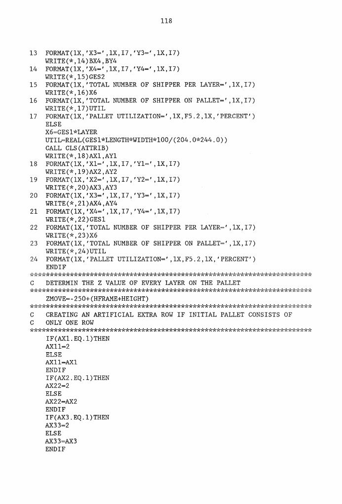
118
13 FORMAT(lX, 'X3=', lX, 17, 'Y3=', lX, 17) WRITE(*,14)BX4,BY4
14 FORMAT(lX, 'X4=', lX, 17, 'Y4=', lX, 17) WRITE(*,15)GES2
15 FORMAT(lX,'TOTAL NUMBER OF SHIPPER PER LAYER=' ,1X,I7) WRITE(*,16)X6
16 FORMAT(lX,'TOTAL NUMBER OF SHIPPER ON PALLET=' ,1X,I7) WRITE(*,17)UTIL
17 FORMAT(lX,'PALLET UTILIZATION=' ,1X,F5.2,1X,'PERCENT') ELSE X6=GESl*LAYER UTIL=REAL(GESl*LENGTH*WIDTH*l00/(204.0*244.0)) CALL CLS(ATTRIB) WRITE(*,18)AX1,AY1
18 FORMAT(lX, 'Xl=', lX, 17, 'Yl=', lX, 17) WRITE(*,19)AX2,AY2
19 FORMAT(lX, 'X2=', lX, 17, 'Y2=', lX, 17) WRITE(*,20)AX3,AY3
20 FORMAT(lX, 'X3=', lX, 17, 'Y3=', lX, 17) WRITE(*,2l)AX4,AY4
21 FORMAT(lX, 'X4=', lX, 17, 'Y4=', lX, 17) WRITE(*,22)GES1
22 FORMAT(lX,'TOTAL NUMBER OF SHIPPER PER LAYER=' ,1X,I7) WRITE(*,23)X6
23 FORMAT(lX,'TOTAL NUMBER OF SHIPPER ON PALLET=' ,1X,I7) WRITE(*,24)UTIL
24 FORMAT(lX,'PALLET UTILIZATION=' ,1X,F5.2,1X,'PERCENT') ENDIF
*********************************************************************** C DETERMIN THE Z VALUE OF EVERY LAYER ON THE PALLET ***********************************************************************
ZMOVE=-250+(HFRAME+HEIGHT) *,b'(************************************************************''c******* C CREATING AN ARTIFICIAL EXTRA ROW IF INITIAL PALLET CONSISTS OF C ONLY ONE ROW ************************************************''c*********''c**,-C*****,b'c**
IF(AXl.EQ.l)THEN AX11=2 ELSE AXll=AXl ENDIF IF(AX2.EQ.l)THEN AX22=2 ELSE AX22=AX2 ENDIF IF(AX3.EQ.l)THEN AX33=2 ELSE AX33=AX3 ENDIF

IF(AX4.EQ.l)THEN AX44=2 ELSE AX44=AX4 ENDIF IF(AYl.EQ.l)THEN AY11=2 ELSE AYll=AYl ENDIF IF(AY2.EQ.l)THEN AY22=2 ELSE AY22=AY2 ENDIF IF(AY3.EQ.l)THEN AY33=2 ELSE AY33=AY3 ENDIF IF(AY4.EQ.l)THEN AY44=2 ELSE AY44=AY4 ENDIF IF(BXl.EQ.l)THEN BX11=2 ELSE BXll=BXl ENDIF IF(BX2.EQ.l)THEN BX22=2 ELSE BX22=BX2 ENDIF IF(BX3.EQ.l)THEN BX33=2 ELSE BX33=BX3 ENDIF IF(BX4.EQ.l)THEN BX44=2 ELSE BX44=BX4 ENDIF IF(BYl.EQ.l)THEN BY11=2 ELSE BYll=BYl ENDIF IF(BY2.EQ.l)THEN
119

BY22=2 ELSE BY22=BY2 ENDIF IF(BY3.EQ.l)THEN BY33=2 ELSE BY33=BY3 ENDIF IF(BY4.EQ.l)THEN BY44=2 ELSE BY44=BY4 ENDIF
120
··k**i'r:******************************************************-k*****-k**°''c**·-k C DETERMINING THE LOWER LEFT, LOWER RIGHT, UPPER RIGHT CORNER C SHIPPER CENTER POINTS FOR ALL 4 POSSIBLE PALLET CONFIGURATIONS *"k******************"k**********************************"k .. k***i'c·-k*·k*****"1'c*
IF(GES2.GE.GESl)THEN LLX1=180.0-((BXl*WIDTH)-(WIDTH/2)) LLY1=290.0+LENGTH/2 LRX1=180-WIDTH/2 LRYl=LLYl URXl=LRXl URY1=290.0+((BYl*LENGTH)-LENGTH/2) Nl=BXll*BYll NlR=BXl*BYl PPRl=BXl
IF(BX2.EQ.O)GOT01000 LLX2=-64.0+LENGTH/2 LLY2=290.0+WIDTH/2 LRX2=LLX2+(BX2-l)*LENGTH LRY2=LLY2 URX2=LRX2 URY2=290.0+((BY2*WIDTH)-WIDTH/2) N2=BX22*BY22 N2R=BX2*BY2 PPR2=BX2
1000 IF(BX3.EQ.O)GOT01001
LLX3=-64.0+WIDTH/2 LLY3=500.0-(BY3*LENGTH-LENGTH/2) LRX3=LLX3+(BX3-l)*WIDTH LRY3=LLY3 URX3=LRX3 URY3=500.0-LENGTH/2 N3=BX33*BY33 N3R=BX3*BY3 PPR3=BX3

121
1001 IF(BX4.EQ.O)GOT01002
LLX4=180.0-((BX4*LENGTH)-(LENGTH/2)) LLY4=500.0-(BY4*WIDTH-WIDTH/2) LRX4=180-LENGTH/2 LRY4=LLY4 URX4=LRX4 URY4=500.0-WIDTH/2 N4=BX44*BY44 N4R=BX4*BY4 PPR4=BX4
1002 ELSE
IF(AX4.EQ.O)GOT01003
LLX1=180.0-((AX4*WIDTH)-(WIDTH/2)) LLY1=290.0+LENGTH/2 LRX1=180-WIDTH/2 LR.Yl=LLYl URXl=LRXl URY1=290.0+((AY4*LENGTH)-LENGTH/2) Nl=AX44*AY44 N1R=AX4*AY4 PPR1=AX4
1003 LLX2=-64.0+LENGTH/2 LLY2=290.0+WIDTH/2 LRX2=LLX2+(AX1-l)*LENGTH LRY2=LLY2 URX2=LRX2 URY2=290.0+((AYl*WIDTH)-WIDTH/2) N2=AX1l*AY11 N2R=AXl*AY1 PPR2=AX1
IF(AX2.EQ.O)GOT01004
LLX3=-64.0+WIDTH/2 LLY3=500.0-(AY2*LENGTH-LENGTH/2) LRX3=LLX3+(AX2-l)*WIDTH LRY3=LLY3 URX3=LRX3 URY3=500.0-LENGTH/2 N3=AX22*AY22 N3R=AX2*AY2
PPR3=AX2
1004 IF(AX3.EQ.O)GOT01005

122
LLX4=180.0-((AX3*LENGTH)-(LENGTH/2)) LLY4=500.0-(AY3*WIDTH-WIDTH/2) LRX4=180-LENGTH/2 LRY4=LLY4 URX4=LRX4 URY4=500.0-WIDTH/2 N4=AX33*AY33 N4R=AX3*AY3 PPR4=AX3
1005 ENDIF
*********************************************************************** C OPENING THE AML FILE FOR CREATING THE CONTROL PROGRAM ***********************************************************************
OPEN(3,FILE='NEW.AML' ,STATUS='NEW') *********************************************************************** C DETERMINE THE# OF IAYERS ***********************************************************************
IAYER=INT(H/HEIGHT+.5) *********************************************************************** C IF DUNNAGE IS REQUESTED, ADD HEIGHT OF DUNNAGE TO Z VALUE FOR C EACH IAYER ***********************************************************************
IF(DUNYES.EQ.l)THEN DUNN=-1 DO 318 I=l,IAYER DUNN=DUNN+l PT(I)=I*HEIGHT-250.+THICK*DUNN
318 CONTINUE ELSE DO 319 I=l,IAYER PT(I)=I*HEIGHT-250.+HFRAME
319 CONTINUE ENDIF
*********************************************************************** C PUTTING Z VALUES INTO A STRING TO ZAP OF THE BIANKS ***********************************************************************
DO 30 I=l,IAYER WRITE(STRl,320)1,PT(I)
320 FORMAT(lX,'Z ',13,' :' ,3X,'NEW' ,1X,F7.2' ;') IF(STR2(3).NE.' ')GOTO 26 STR3(l)=STR2(1) STR3(2)=STR2(2) III=3 DO 321 II =3,12 IF(STR2(II).NE.' ')GOTO 322
321 CONTINUE 322 CONTINUE
DO 323 JJ=II,60 STR3(III)=STR2(JJ)

IF(STR2(JJ).EQ.' ;')GOTO 324 III=III+l
323 CONTINUE
123
324 CONTINUE WRITE(3,25)(STR3(KK),KK=l,III)
25 FORMAT(60Al) GOT029
26 CONTINUE DO 27 III=l,60 IF(STR2(III).EQ.';')GOTO 28
27 CONTINUE 28
29 30
CONTINUE WRITE(3,25)(STR2(KK),KK=l,III) CONTINUE CONTINUE
*********************************************************************** C WRITE GLOBAL PALLET CONST. INTO AML FILE ***********************************************************************
WRITE(3,31)LLX1,LLY1 31 FORMAT(lX,'LLl: NEW PT(' ,F7.2,' ,' ,F7.2,' ,0,90);')
WRITE(3,32)LRX1,LRY1 32 FORMAT(lX,'LRl: NEW PT(' ,F7.2,' ,' ,F7.2,' ,0,90);')
WRITE(3,33)URX1,URY1 33 FORMAT(lX,'URl: NEW PT(' ,F7.2,' ,' ,F7.2,' ,0,90);')
WRITE(3,34)Nl 34 FORMAT(lX,'Nl: NEW' ,13,';')
WRITE(3,35)N1R 35 FORMAT(lX,'NlREAL: NEW' ,13,';')
WRITE(3,36)PPR1 36 FORMAT(lX,'PPRl: NEW' ,13,';')
WRITE(3,37)LLX2,LLY2 37 FORMAT(1X,'LL2: NEW PT(' ,F7.2,' ,' ,F7.2,' ,0,0);')
WRITE(3,38)LRX2,LRY2 38 FORMAT(lX, 'LR2: NEW PT(' ,F7.2,' ,' ,F7.2,' ,0,0);')
WRITE(3,39)URX2,URY2 39 FORMAT(1X,'UR2: NEW PT(' ,F7.2,' ,' ,F7.2,' ,0,0);')
WRITE(3,40)N2R 40 FORMAT(1X,'N2REAL: NEW' ,13,' ;')
WRITE(3,41)N2 41 FORMAT(1X,'N2: NEW' ,13,' ;')
WRITE(3,42)PPR2 42 FORMAT(1X,'PPR2: NEW' ,13,';')
WRITE(3,43)LLX3,LLY3 43 FORMAT(1X,'LL3: NEW PT(' ,F7.2,' ,' ,F7.2,' ,0,0);')
WRITE(3,44)LRX3,LRY3 44 FORMAT(1X,'LR3: NEW PT(' ,F7.2,' ,' ,F7.2,' ,0,0);')
WRITE(3,45)URX3,URY3 45 FORMAT(1X,'UR3: NEW PT(' ,F7.2,' ,' ,F7.2,' ,0,0);')
WRITE(3,46)N3

46 FORMAT(lX,'N3: NEW' ,13,' ;') WRITE(3,47)N3R
124
47 FORMAT(lX,'N3REAL: NEW' ,13,';') WRITE(3,48)PPR3
48 FORMAT(lX,'PPR3: NEW' ,13,';')
WRITE(3,49)LLX4,LLY4 49 FORMAT(lX,'LL4: NEW PT(' ,F7.2,' ,' ,F7.2,' ,0,90);')
WRITE(3,50)LRX4,LRY4 50 FORMAT(lX,'LR4: NEW PT(' ,F7.2,' ,' ,F7.2,' ,0,90);')
WRITE(3,5l)URX4,URY4 51 FORMAT(lX,'UR4: NEW PT(' ,F7.2,' ,' ,F7.2,' ,0,90);')
WRITE(3,52)N4R 52 FORMAT(lX,'N4REAL: NEW' ,13,' ;')
WRITE(3,53)N4 53 FORMAT(lX,'N4: NEW' ,13,' ;')
WRITE(3,54)PPR4 54 FORMAT(lX,'PPR4: NEW' ,13,';')
WRITE(3,55)LAYER 55 FORMAT(lX,'LAYER: NEW' ,13,' ;') *********************************************************************** C DECLARATION OF DI/DO POINTS ***********************************************************************
WRITE(3,56) 56 FORMAT(lX,'OPER_ATTNHORNl: NEW 10;')
WRITE(3,57) 57 FORMAT(lX,'OFF:NEW 0;' ,/,'OPER RETRY: NEW l;' ,/,'ON:NEW l;' ,/
*'OPER ATTNHORN: NEW 11;' ,/,'PORT: NEW 5;')
*********************************************************************** C WRITING GLOBAL VARIABLES INTO AML FILE ***********************************************************************
WRITE(3,58) 58 FORMAT(lX,'PITT: STATIC COUNTER;' ,/,'TURN :STATIC COUNTER;')
WRITE(3,59) 59 FORMAT(lX,'SAMPLEl: STATIC PALLET(LLl,LRl,URl,PPRl,Nl);')
WRITE(3,60) 60 FORMAT(lX,'SAMPLE2: STATIC PALLET(LL2,LR2,UR2,PPR2,N2);')
WRITE(3,61) 61 FORMAT(lX,'SAMPLE3: STATIC PALLET(LL3,LR3,UR3,PPR3,N3);')
WRITE(3,62) 62 FORMAT(lX,'SAMPLE4: STATIC PALLET(LL4,LR4,UR4,PPR4,N4);')
WRITE(3,63)INTERX,INTERY,INTERZ,INTERR,SEMIX,SEMIY, *SEMIZ,SEMIR,MATE,CARLX,CARLY,CARLZ,CARLR
63 FORMAT(lX,'INTER:NEW PT(' ,F7.2,' ,' ,F7.2,' ,' ,F7.2,' ,' ,F7.2,');' ,/ * ' SEMI : NEW PT ( ' , F7 . 2 , ' , ' , F7 . 2 , ' , ' , F7 . 2 , ' , ' , F7 . 2 , ' ) ; ' , / *'RESTART:NEW 5;' ,/,'MATE: NEW' ,F7.2,' ;' ,/,'ZYLINDERl: NEW l;' ,/ *'ZYLINDER2: NEW 5;' ,/,'STEP: NEW 16;' ,/,'HOMEl: NEW 9;' ,/ *'CAROUSSEL: NEW PT(' ,F7.2,' ,' ,F7.2,' ,' ,F7.2,' ,' ,F7.2,');' ,/ *'PALLET CENTER: NEW PT(0,0,0,0);' ,/

125
,\-'DUNN_PICKUP: NEW PT(0,0,0,0); ') WRITE(3,64)PICKZ
64 FORMAT(lX,'PICKZ: NEW' ,F7.2,';') WRITE(3,65)PICKX,PICKY
65 FORMAT(lX,'PICKY: NEW PT(' ,F7.2,' ,' ,F7.2,' ,0,0 );') *********************************************************************** C HEIGHT OF DUNNAGE PILE AFTER EACH LAYER ***********************************************************************
DO 67 I=l,LAYER DUZ(I)=PT(I)+THICK WRITE(3,66)I,DUZ(I)
66 FORMAT(lX,'DUZ' ,Il,':NEW' ,F7.2,' ;') 67 CONTINUE *********************************************************************** C START OF THE MAIN SUBROUTINE ***********************************************************************
WRITE(3,68) 68 FORMAT(lX,'MAINPROG:SUBR;') *********************************************************************** C SET HOME SUBROUTINE TURNS THE CROUSSEL TO KNOWN POSITION ***********************************************************************
WRITE(3,69) 69 FORMAT(lX,'SET_HOME:SUBR;')
WRITE(3,70) 70 FORMAT(lX,'LOOP:WRITEO(STEP,OFF);DELAY(O.l);WRITEO(STEP,ON);' ,/
*'DELAY(O.l);TESTI(HOMEl,ON,DONE);' ,/ *'BRANCH(LOOP);' ,/,'DONE:BREAKPOINT;' ,/,'END;')
*********************************************************************** C ROTATE SUBROUTINE ROTATES THE CAROUSSEL TO THE REQUESTED DEGREE ********************************************************************,\-*,\-
WRITE ( 3, 71) 71 FORMAT(lX,'ROTATE:SUBR(DEGREE);')
WRITE(3,72) 72 FORMAT(lX,'SETC(TURN,l);LOOP:WRITEO(STEP,OFF);DELAY(0.1);' ,/
*'WRITEO(STEP,ON);DELAY(0.1);' ,/ *'TESTC(TURN,DEGREE,DONE);' ,/,'INCR(TURN);BRANCH(LOOP);' ,/ *'DONE:BREAKPOINT;' ,/,'END;')
IF(WEIGHT.EQ.l)THEN
C IF SHIPPER WEIGHT IS IN THE RANGE OF O - 5 LB, THE ROBOT WILL C PICK UP THE SMALL VACUUM GRIPPER *,°'******,°'********************************************************'b°'****
WRITE(3,73) 73 FORMAT(lX,'INTERCHANGE_BEGIN_REG:SUBR;')
WRITE(3,74) 74 FORMAT(lX,'PMOVE(INTER);SET_HOME;PAYLOAD(ll);ZONE(l);' ,/
*'ZMOVE(MATE);WRITEO(ZYLINDER1,0N);DELAY(2);PMOVE(SEMI);' ,/ *'WRITEO(l5,0N);ZONE(O);PAYLOAD(O);' ,/ *'ZMOVE(O);WRITEO(l5,0N);END;')
ELSE

126
*********************************************************************** C IF SHIPPER WEIGHT IS IN THE RANGE OF 5 - 10 LB, THE ROBOT WILL C PICK UP THE BIG VACUUM GRIPPER **************************************************************"k*·k**··J:*·k·k
WRITE(3,75) 75 FORMAT(lX,'INTERCHANGE_BEGIN_HEAVY:SUBR;')
WRITE(3,76) 76 FORMAT(lX,'PMOVE(INTER);PAYLOAD(ll);SET_HOME;ROTATE(25);' ,/
*'ZONE(l);ZMOVE(MATE);WRITEO(ZYLINDERl,ON);ZONE(O);' ,/ *'DELAY(2);PMOVE(SEMI);LINEAR(O);' ,/,'WRITEO(lS,ON);' ,/ *'PAYLOAD(O);ZMOVE(O);WRITEO(lS,ON);' ,/, 'END;')
ENDIF IF(DUNYES.EQ.l.AND.WEIGHT.EQ.l)THEN
***'k*********************************************************--,'<*··k*·k****·k C C
DUNN GRIPPER ROTATE SUBROUTINE ROTATES THE CAROUSSEL TO ENABLE - -THE ROBOT TO PICK UP THE DUNNAGE GRIPPER ***********************************************************************
WRITE(3,77) 77 FORMAT(lX,'DUNN_GRIPPER_ROTATE:SUBR(PLACES);')
WRITE(3,78) 78 FORMAT(lX,'PMOVE(SEMI);LINEAR(l);SET_HOME;PMOVE(CAROUSSEL);' ,/
*'WRITEO(ZYLINDER1,0FF);DELAY(2);WRITEO(ZYLINDER2,0N);' ,/ *'DELAY(4);WRITEO(ZYLINDER2,0FF);DELAY(S);ZMOVE(O);' ,/ *'ROTATE(l00);DELAY(2);ZMOVE(MATE);WRITEO(ZYLINDER1,0N);' ,/ *'DELAY(2);PMOVE(SEMI);LINEAR(O);PMOVE(DUNN_PICKUP);' ,/ *'GRASP;DELAY(l);PMOVE(PALLET_CENTER);GUARDI(8,0N);' ,/ *'ZMOVE(PLACES);NOGUARD;RELEASE;DELAY(l);ZMOVE(O);' ,/ *'PMOVE(SEMI);LINEAR(l);SET_HOME;ROTATE(SO);PMOVE(CAROUSSEL);' ,/ *'WRITEO(ZYLINDER1,0FF);DELAY(2);WRITEO(ZYLINDER2,0N);' ,/ '""'DELAY(4) ;WRITEO(ZYLINDER2,0FF) ;DELAY(S) ;ZMOVE(O);' ,/ *'SET_HOME;DELAY(2);ZMOVE(MATE);WRITEO(ZYLINDER1,0N);' ,/ *'DELAY(2);PMOVE(SEMI);LINEAR(O);' ,/,'END;')
ENDIF
IF(DUNYES.EQ.l.AND.WEIGHT.NE.l)THEN WRITE(3,79)
79 FORMAT(lX,'DUNN_GRIPPER_ROTATE:SUBR(PLACES);') WRITE(3,80)
80 FORMAT(lX, 'PMOVE(SEMI);LINEAR(l);SET_HOME;' ,/ ·k' ROTATE ( 25) ; PMOVE ( CAROUSSEL) ; ' , / *'WRITEO(ZYLINDER1,0FF);DELAY(2);WRITEO(ZYLINDER2,0N);' ,/ *'DELAY(4);WRITEO(ZYLINDER2,0FF);DELAY(S);ZMOVE(O);' ,/ *'ROTATE(25);DELAY(2);ZMOVE(MATE);WRITEO(ZYLINDER1,0N);' ,/ *'DELAY(2);PMOVE(SEMI);LINEAR(O);PMOVE(DUNN PICKUP);',/ *'GRASP;DELAY(l);PMOVE(PALLET_CENTER);GUARDI(8,0N);' ,/ *'ZMOVE(PLACES);NOGUARD;RELEASE;DELAY(l);ZMOVE(O);' ,/ *'PMOVE(SEMI);LINEAR(l);SET_HOME;ROTATE(SO);PMOVE(CAROUSSEL);' ,/ *'WRITEO(ZYLINDER1,0FF);DELAY(2);WRITEO(ZYLINDER2,0N);' ,/ *'DELAY(4);WRITEO(ZYLINDER2,0FF);DELAY(S);ZMOVE(O);' ,/ *'ROTATE(l50);DELAY(2);ZMOVE(MATE);WRITEO(ZYLINDER1,0N);' ,/ *'DELAY(2);PMOVE(SEMI);LINEAR(O);' ,/,'END;')

127
ENDIF *********************************************************************** C WAIT PART SUBROUTINE SIGNALS THE CONTROLLER WHEN A PART IS C PRESENT AT THE PICK UP STATION, IF A PART DOES NOT ARRIVE C AFTER 15 SEC., THE OPERATER WILL BE WARNED *****************************************************************~"c**~b'c*
WRITE(3,81) 81 FORMAT(lX,'WAIT_PART:SUBR;' ,/,'WAITI(PORT,ON,15,TROUBLE);' ,/
*'BRANCH(DONE);' ,/,'TROUBLE:WRITEO(OPER_ATTNHORN,ON);' ,/ *'WAITI(OPER_RETRY,OFF,O);WAITI(OPER_RETRY,ON,O);' ,/ *'WAITI(OPER_RETRY,OFF,O);WRITEO(OPER_ATTNHORN,OFF);' ,/ *'DONE:BREAKPOINT;' ,/,'END;')
*********************************************************************** C NEW PALLET SUBROUTINE WILL WARN THE OPERATER THAT THE CURRENT C PALLET IS STACKED TO CAPACITY AND GIVES HIM/HER 20 SEC. TO C REPIACE THE CURRENT PALLET WITH AN EMPTY ONE. IF PALLET IS C NOT REPIACED, THE ROBOT WILL PARK THE GRIPPER AND WAITS TO C BE RESTARTED. ***********************************************************************
IF(WEIGHT.EQ.l)THEN WRITE(3,82)
82 FORMAT(lX,'NEW_PALLET:SUBR;' ,/,'WRITEO(OPER_ATTNHORNl,ON);' ,/ *'WAITI(OPER_RETRY,OFF,5);WAITI(OPER_RETRY,ON,10,LOOP_PARK);' ,/ *'WAITI(OPER_RETRY,OFF,10);' ,/,'WRITEO(OPER_ATTNHORNl,OFF);' ,/ *'BRANCH(DONE);' ,/,'LOOP_PARK:ZMOVE(O);PMOVE(SEMI);LINEAR(l); ',/ *'WRITEO(OPER_ATTNHORN1,0FF);WRITEO(l5,0FF);SET_HOME;' ,/ *'PMOVE(CAROUSSEL);WRITEO(ZYLINDER1,0FF);DEIAY(3);' ,/ *'WRITEO(ZYLINDER2,0N);DEIAY(3);WRITEO(ZYLINDER2,0FF);' ,/ *'DEIAY(5);LINEAR(l);ZMOVE(-150);LINEAR(O);ZMOVE(O);' ,/ *'DONE:BREAKPOINT;WRITEO(OPER_ATTNHORNl,OFF);' ,/ *'PMOVE(PT(650,0,0,0));' ,/,'END;')
ELSE WRITE(3,83)
83 FORMAT(lX,'NEW_PALLET:SUBR;' ,/,'WRITEO(OPER_ATTNHORNl,ON);' ,/ *'WAITI(OPER_RETRY,OFF,5);WAITI(OPER_RETRY,ON,10,LOOP_PARK);' ,/ *'WAITI(OPER_RETRY,OFF,10);' ,/,'WRITEO(OPER_ATTNHORNl,OFF);' ,/ *'BRANCH(DONE);' ,/,'LOOP PARK:ZMOVE(O);PMOVE(SEMI);LINEAR(l);' ,/ *'WRITEO(l5,0FF);WRITEO(OPER_ATTNHORN1,0FF);SET_HOME;ROTATE(25);' ,/ *'PMOVE(CAROUSSEL);WRITEO(ZYLINDER1,0FF);DEIAY(3);' ,/ *'WRITEO(ZYLINDER2,0N);DEIAY(3);WRITEO(ZYLINDER2,0FF);' ,/ *'DEIAY(5);LINEAR(l);ZMOVE(-150);LINEAR(O);ZMOVE(O);' ,/ *'DONE:BREAKPOINT;WRITEO(OPER_ATTNHORNl,OFF);' ,/ *'PMOVE(PT(650,0,0,0));' ,/,'END;')
ENDIF *********************************************************************** C PICKUP SUBROUTINE STACKS THE FIRST PART OF EVERY ODD IAYER ***********************************************************************
WRITE(3,84) 84 FORMAT(lX,'PICKUP:SUBR(PIACEl);')
WRITE(3,85) 85 FORMAT(lX,'SET: SETPART(SAMPLEl,l);')

128
WRITE(3,86) 86 FORMAT(lX,'LOOP:WAIT_PART;PMOVE(PICKY);ZMOVE(PICKZ);')
WRITE(3,87) 87 FORMAT(lX,'GRASP;DELAY(l);ZMOVE(O);')
WRITE(3,88) 88 FORMAT(lX,'GETPART(SAMPLEl);GUARDI(8,l);ZMOVE(PLACE1);' ,/
*'NOGUARD;RELEASE;DELAY(l);') WRITE(3,89)
89 FORMAT(lX,'ZMOVE(O);TESTP(SAMPLEl,NlREAL,DONE);') WRITE(3,90)
90 FORMAT(lX,'NEXTPART(SAMPLEl);') WRITE(3,91)
91 FORMAT(lX,'BRANCH(LOOP);') WRITE(3,92)
92 FORMAT(lX,'DONE:BREAKPOINT;') WRITE(3,93)
93 FORMAT(lX,'END;') ***"k**************************************************************··k*··k** C OLDPR SUBROUTINE STACKS THE SECOND PART OF EVERY ODD LAYER ***********************************************************************
WRITE(3,94) 94 FORMAT(1X,'OLDPR:SUBR(PLACE2);')
WRITE(3,95) 95 FORMAT(lX,'SET: SETPART(SAMPLE2,1);')
WRITE(3,96) 96 FORMAT(lX,'LOOP:WAIT_PART;PMOVE(PICKY);ZMOVE(PICKZ);')
WRITE(3,97) 97 FORMAT(lX, 'GRASP;DELAY(l);ZMOVE(O);')
WRITE(3,98) 98 FORMAT(lX, 'GETPART(SAMPLE2);GUARDI(8,l);ZMOVE(PLACE2);' ,/
*'NOGUARD;RELEASE;DELAY(l);') WRITE(3,99)
99 FORMAT(lX, 'ZMOVE(O);TESTP(SAMPLE2,N2REAL,DONE);') WRITE(3,100)
100 FORMAT(lX, 'NEXTPART(SAMPLE2);') WRITE(3,101)
101 FORMAT(lX,'BRANCH(LOOP);') WRITE(3,102)
102 FORMAT(lX,'DONE:BREAKPOINT;') WRITE(3,103)
103 FORMAT(lX,'END;') *****************************************-k************i'r:**********..,~*·k-;'(··k··k C NEWPR SUBROUTINE STACKS THE FIRST PART OF EVERY EVEN LAYER ***********************************************************************
WRITE(3,104) 104 FORMAT(1X,'NEWPR:SUBR(PLACE3);')
WRITE(3,105) 105 FORMAT(lX, 'SET: SETPART(SAMPLE3,l);')
WRITE(3,106) 106 FORMAT(lX, 'LOOP:WAIT_PART;PMOVE(PICKY);ZMOVE(PICKZ);')
WRITE(3,107)

129
107 FORMAT(lX,'GRASP;DELAY(l);ZMOVE(O);') WRITE(3,108)
108 FORMAT(1X,'GETPART(SAMPLE3);GUARDI(8,l);ZMOVE(PLACE3);' ,/ *'NOGUARD;RELEASE;DELAY(l);') WRITE(3,109)
109 FORMAT(1X,'ZMOVE(O);TESTP(SAMPLE3,N3REAL,DONE);') WRITE(3,110)
110 FORMAT(1X,'NEXTPART(SAMPLE3);') WRITE(3,111)
111 FORMAT(lX,'BRANCH(LOOP);') WRITE(3,112)
112 FORMAT(lX,'DONE:BREAKPOINT;') WRITE(3,113)
113 FORMAT(lX,'END;') *'':**************************************************************''(****** C LAST PROGRAM STACKS THE SECOND PART OF EVERY EVEN LAYER ***********************************************************************
WRITE(3,114) 114 FORMAT(1X,'LAST:SUBR(PLACE4);')
WRITE(3,115) 115 FORMAT(lX,'SET: SETPART(SAMPLE4,l);')
WRITE(3,116) 116 FORMAT(lX,'LOOP:WAIT_PART;PMOVE(PICKY);ZMOVE(PICKZ);')
WRITE(3,117) 117 FORMAT(lX,'GRASP;DELAY(l);ZMOVE(O);')
WRITE(3,118) 118 FORMAT(1X,'GETPART(SAMPLE4);GUARDI(8,l);ZMOVE(PLACE4);' ,/
*'NOGUARD;RELEASE;DELAY(l);') WRITE(3,119)
119 FORMAT(1X,'ZMOVE(O);TESTP(SAMPLE4,N4REAL,DONE);') WRITE(3,120)
120 FORMAT(1X,'NEXTPART(SAMPLE4);') WRITE(3,121)
121 FORMAT(lX,'BRANCH(LOOP);') WRITE(3,122)
122 FORMAT(lX,'DONE:BREAKPOINT;') WRITE(3,123)
123 FORMAT(lX,'END;') I=l
**'b':***********''(**************************************************''c**** C CALLING THE DIFFERENT SUBROUTINES FOR ALL DIFFERENT CASES
IF(DUNYES.EQ.l)THEN IF(WEIGHT.EQ.l)THEN WRITE(3,124)
124 FORMAT(lX,'INTERCHANGE_BEGIN_REG;') ELSE WRITE(3,125)
125 FORMAT(lX,'INTERCHANGE_BEGIN HEAVY;') ENDIF W=l

130
WRITE(3,126) 126 FORMAT(lX,'OVER:SETC(PITT,0);')
127 CONTINUE
IF(I. LE. 4)THEN
WRITE(3,128)I 128 FORMAT(lX,'PICKUP(Z' ,Il,');')
WRITE(3,129)I 129 FORMAT(lX,'OLDPR(Z' ,Il,');')
WRITE(3,133)I 133 FORMAT(lX,'NEWPR(Z' ,Il,');')
WRITE(3,134)I 134 FORMAT(lX,'LAST(Z' ,Il,');')
WRITE(3, 135) 135 FORMAT(lX,'INCR(PITT);')
WRITE(3,136)WW,WW+l,WW,WW+l,I 136 FORMAT(lX,'TESTC(PITT,LAYER,LOOP' ,Il,');' ,/
*'BRANCH(LOOP' 11 ')·' / 'LOOP' 11 '·NEW PALLET·' / ' , ' ' ' ' ' . - ' , *'WAITI(RESTART,OFF,O);WAITI(RESTART,ON,O);WAITI(RESTART,OFF,0);' ,/ *'BRANCH(OVER);' ,/,'LOOP' ,Il,' :DUNN GRIPPER ROTATE(DUZ' ,Il,');') - -WW=WW+2
IF(I.EQ.LAYER)GOT0168 I=I+l GOT0127
ELSE WW=WW+4
137 WRITE(3,138)I 138 FORMAT(lX,'PICKUP(Z' ,Il,');')
IF(N2R.EQ.O)GOT0140 WRITE(3,139)I
139 FORMAT(lX,'OLDPR(Z' ,Il,');') 140 IF(N3R.EQ.O)GOT0141
WRITE(3,142)I 142 FORMAT(lX,'NEWPR(Z' ,Il,');')
141 WRITE(3,143)I 143 FORMAT(lX,'LAST(Z' ,Il,');')
WRITE(3,144) 144 FORMAT(lX,'INCR(PITT);')
WRITE(3,145)WW,WW+l,WW,WW+l,I 145 FORMAT(lX,'TESTC(PITT,LAYER,LOOP' ,12,');' ,/
*'BRANCH(LOOP' ,12,');' ,/,'LOOP' ,12,':NEW_PALLET;' ,/ 1~• BRANCH(OVER);' ,/,'LOOP', 12,': DUNN_GRIPPER_ROTATE(DUZ', 11, '); ') WW=WW+2 IF(I.EQ.LAYER)GOT0168 I=I+l

GOT0137 ENDIF
ELSE
WW=l IF(WEIGHT.EQ.l)THEN 'WRITE(3,146)
131
146 FORMAT(lX,'INTERCHANGE_BEGIN_REG;') ELSE 'WRITE(3,147)
147 FORMAT(lX,'INTERCHANGE_BEGIN_HEAVY;') ENDIF
'WRITE(3,148) 148 FORMAT(lX,'OVER:SETC(PITT,0);')
149 CONTINUE
IF(I. LE. 4)THEN
'WRITE(3,150)I 150 FORMAT(lX,'PICKUP(Z' ,Il,');')
IF(N2R.EQ.O)GOTO 152 'WRITE(3,15l)I
151 FORMAT(lX,'OLDPR(Z' ,Il,');') 152 IF(N3R.EQ.O)GOT0155
'WRITE(3,154)I 154 FORMAT(lX,'NEWPR(Z' ,Il,');')
155 'WRITE(3,156)I 156 FORMAT(lX,'LAST(Z' ,Il,');')
'WRITE(3,157) 157 FORMAT(lX,'INCR(PITT);')
'WRITE(3,158)WW,WW+l,WW 158 FORMAT(lX,'TESTC(PITT,LAYER,LOOP' ,Il,');' ,/
*'BRANCH(LOOP' 11 ')·' / 'LOOP' 11 '·NEW PALLET·' / , , ' ' ' ' ' ' . - ' ' *'WAITI(RESTART,OFF,O);WAITI(RESTART,ON,O);WAITI(RESTART,OFF,0);' ,/ *'BRANCH(OVER);') 'WRITE(3,159)WW+l
159 FORMAT(lX,'LOOP' ,Il,':DELAY(l);') IF(I.EQ.LAYER)GOT0168 WW=WW+2 I=I+l GOT0149
ELSE WW=WW+4 'WRITE(3,160)I
160 FORMAT(lX,'PICKUP(Z' ,Il,');')

WRITE(3,16l)I IF(N2R.EQ.O)GOT0180
161 FORMAT(lX,'OPDPR(Z' ,Il,');') 180 IF(N3R.EQ.O)GOT0181
WRITE(3,162)I 162 FORMAT(lX,'NEWPR(Z' ,Il,');')
181 WRITE(3,163)I 163 FORMAT(lX,'LAST(Z' ,Il,');')
WRITE(3,164) 164 FORMAT(lX,'INCR(PITT);')
WRITE(3,165)WW,WW+l,WW
132
165 FORMAT(lX,'TESTC(PITT,LAYER,LOOP' ,12,');' ,/ *'BRANCH(LOOP' ,,12,');' ,/,'LOOP' ,12,':NEW PALLET;',/ *'WAITI(RESTART,OFF,O);WAITI(RESTART,ON,O);WAITI(RESTART,OFF,O);' ,/ *'BRANCH(OVER);')
WRITE(3,166)WW+l 166 FORMAT(lX,'LOOP' ,I2,':DELAY(l);')
IF(I.EQ.LAYER)GOT0168 WW=WW+2 I=I+l GOT0149
ENDIF ENDIF
167 CONTINUE 168 WRITE(3,169) 169 FORMAT(lX,'END;') 170 STOP
END *********************************************************************** CSUBROUTINE TO INTERACTIVELY COMMUNICATE WITH THE USER ***********************************************************************
SUBROUTINE PRINT (ROW,COL,STRING,LENGT) INTEGER PAGE, ROW, COL, LENGT, CHAR CHARACTER STRING(LENGT) CALL CURPAG(PAGE) CALL LOCATE(PAGE,ROW,COL) DO 171 I=l,LENGT CHAR=ICHAR(STRING(I)) CALL WRTTY(CHAR)
171 CONTINUE RETURN END

APPENDIX C
AML/E PROGRAM
133

Zl: NEW -224.60; Z2: NEW -194.12; Z3: NEW -163.64; LLl: NEW PT( -23.36, LRl: NEW PT( 139.36, URl: NEW PT( 139.36, Nl: NEW 6; NlREAL: NEW 6; PPRl: NEW 3;
134
320.48,0,90); 320.48,0,90); 381. 44, 0, 90) ;
LL2: NEW PT( -33.52, 458.06,0,0); LR2: NEW PT( 159.52, 458.06,0,0); UR2: NEW PT( 159.52, 467.06,0,0); N2REAL: NEW 4; N2: NEW 8; PPR2: NEW 4; LL3: NEW PT( -33.52, 336.14,0,0); LR3: NEW PT( 159.52, 336.14,0,0); UR3: NEW PT( 159.52, 336.14,0,0); N3: NEW 8; N3REAL: NEW 4; PPR3: NEW 4; LL4: NEW PT( -23.36, 407.26,0,90); LR4: NEW PT( 139.36, 407.26,0,90); UR4: NEW PT( 139.36, 468.22,0,90);
6; N4: NEW 6; N4REAL: NEW PPR4: NEW 3; LAYER: NEW 3; OPER_ATTNHORNl: NEW 10; OFF:NEW O;
OPER_RETRY: NEW 1; ON:NEW 1; OPER_ATTNHORN: NEW 11; PORT: NEW 5;
PITT: STATIC COUNTER; TURN :STATIC COUNTER;
SAMPLEl: STATIC PALLET(LLl,LRl,URl,PPRl,Nl); SAMPLE2: STATIC PALLET(LL2,LR2,UR2,PPR2,N2); SAMPLE3: STATIC PALLET(LL3,LR3,UR3,PPR3,N3); SAMPLE4: STATIC PALLET(LL4,LR4,UR4,PPR4,N4); INTER:NEW PT(-401.00,-318.30, .00, 54.00);
SEMI:NEW PT(-401.00,-200.00,-212.00, 54.00); RESTART:NEW 5; MATE: NEW -214.60; ZYLINDERl: NEW 1; ZYLINDER2: NEW 5; STEP: NEW 16; HOMEl: NEW 9; CAROUSSEL: NEW PT(-401.00,-318.30,-212.00, 54.00); PALLET_CENTER: NEW PT(0,0,0,0); DUNN_PICKUP: NEW PT(0,0,0,0);
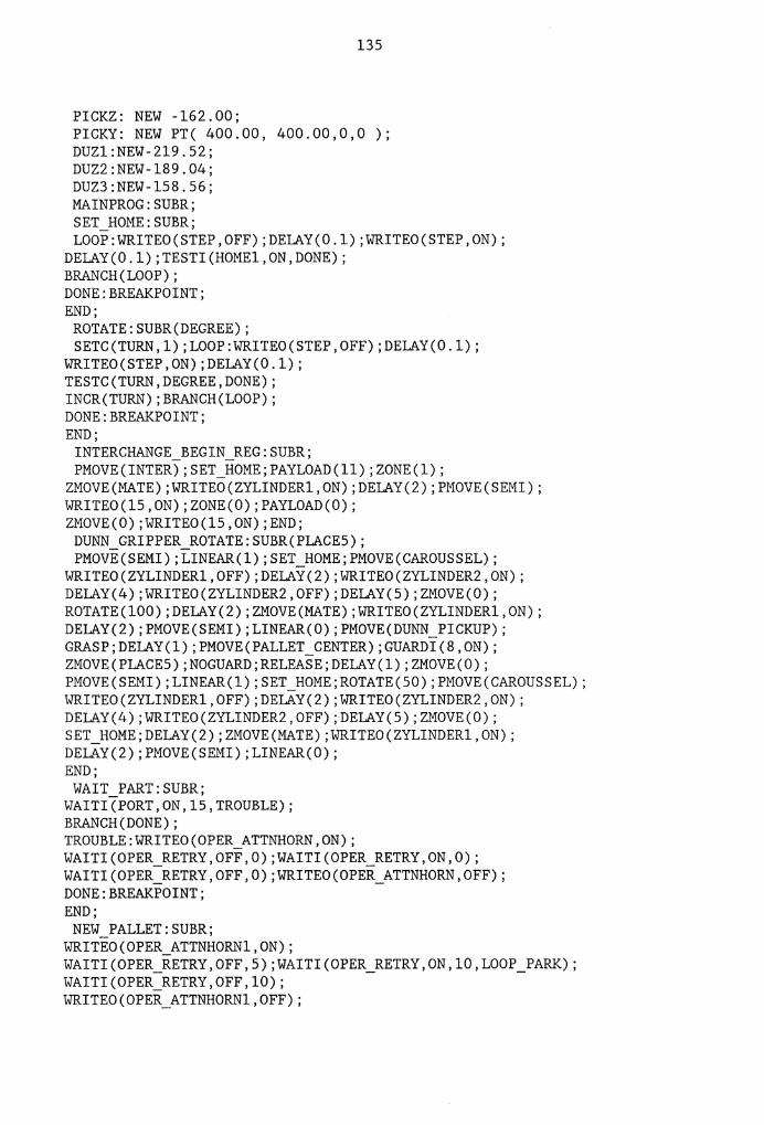
135
PICKZ: NEW -162.00; PICKY: NEW PT( 400.00, 400.00,0,0 ); DUZl:NEW-219.52; DUZ2:NEW-189.04; DUZ3:NEW-158.56; MAINPROG:SUBR; SET_HOME:SUBR; LOOP:WRITEO(STEP,OFF);DELAY(O.l);WRITEO(STEP,ON);
DELAY(O.l);TESTI(HOMEl,ON,DONE); BRANCH(LOOP); DONE:BREAKPOINT; END; ROTATE:SUBR(DEGREE); SETC(TURN,l);LOOP:WRITEO(STEP,OFF);DELAY(0.1);
WRITEO(STEP,ON);DELAY(O.l); TESTC(TURN,DEGREE,DONE); INCR(TURN);BRANCH(LOOP); DONE:BREAKPOINT; END;
INTERCHANGE_BEGIN_REG:SUBR; PMOVE(INTER);SET_HOME;PAYLOAD(ll);ZONE(l);
ZMOVE(MATE);WRITEO(ZYLINDER1,0N);DELAY(2);PMOVE(SEMI); WRITEO(lS,ON);ZONE(O);PAYLOAD(O); ZMOVE(O);WRITEO(lS,ON);END; DUNN_GRIPPER_ROTATE:SUBR(PLACES); PMOVE(SEMI);LINEAR(l);SET_HOME;PMOVE(CAROUSSEL);
WRITEO(ZYLINDER1,0FF);DELAY(2);WRITEO(ZYLINDER2,0N); DELAY(4);WRITEO(ZYLINDER2,0FF);DELAY(S);ZMOVE(O); ROTATE(100);DELAY(2);ZMOVE(MATE);WRITEO(ZYLINDER1,0N); DELAY(2);PMOVE(SEMI);LINEAR(O);PMOVE(DUNN_PICKUP); GRASP;DELAY(l);PMOVE(PALLET_CENTER);GUARDI(8,0N); ZMOVE(PLACES);NOGUARD;RELEASE;DELAY(l);ZMOVE(O); PMOVE(SEMI);LINEAR(l);SET_HOME;ROTATE(SO);PMOVE(CAROUSSEL); WRITEO(ZYLINDER1,0FF);DELAY(2);WRITEO(ZYLINDER2,0N); DELAY(4);WRITEO(ZYLINDER2,0FF);DELAY(S);ZMOVE(O); SET_HOME;DELAY(2);ZMOVE(MATE);WRITEO(ZYLINDER1,0N); DELAY(2);PMOVE(SEMI);LINEAR(O); END; WAIT_PART:SUBR;
WAITI(PORT,ON,15,TROUBLE); BRANCH(DONE); TROUBLE:WRITEO(OPER_ATTNHORN,ON); WAITI(OPER_RETRY,OFF,O);WAITI(OPER_RETRY,ON,O); WAITI(OPER_RETRY,OFF,O);WRITEO(OPER_ATTNHORN,OFF); DONE:BREAKPOINT; END; NEW_PALLET:SUBR;
WRITEO(OPER_ATTNHORNl,ON); WAITI(OPER_RETRY,OFF,S);WAITI(OPER_RETRY,ON,10,LOOP_PARK); WAITI(OPER_RETRY,OFF,10); WRITEO(OPER_ATTNHORNl,OFF);
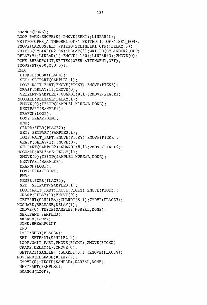
136
BRANCH(DONE); LOOP_PARK:ZMOVE(O);PMOVE(SEMI);LINEAR(l); WRITEO(OPER_ATTNHORN1,0FF);WRITEO(l5,0FF);SET_HOME; PMOVE(CAROUSSEL);WRITEO(ZYLINDER1,0FF);DELAY(3); WRITEO(ZYLINDER2,0N);DELAY(3);WRITEO(ZYLINDER2,0FF); DELAY(5);LINEAR(l);ZMOVE(-150);LINEAR(O);ZMOVE(O); DONE:BREAKPOINT;WRITEO(OPER_ATTNHORNl,OFF); PMOVE(PT(650,0,0,0)); END;
PICKUP:SUBR(PLACEl); SET: SETPART(SAMPLEl,l); LOOP:WAIT_PART;PMOVE(PICKY);ZMOVE(PICKZ); GRASP;DELAY(l);ZMOVE(O); GETPART(SAMPLEl);GUARDI(8,l);ZMOVE(PLACEl);
NOGUARD;RELEASE;DELAY(l); ZMOVE(O);TESTP(SAMPLEl,NlREAL,DONE); NEXTPART(SAMPLEl); BRANCH(LOOP); DONE:BREAKPOINT; END; OLDPR:SUBR(PLACE2); SET: SETPART(SAMPLE2,l); LOOP:WAIT_PART;PMOVE(PICKY);ZMOVE(PICKZ); GRASP;DELAY(l);ZMOVE(O); GETPART(SAMPLE2);GUARDI(8,l);ZMOVE(PLACE2);
NOGUARD;RELEASE;DELAY(l); ZMOVE(O);TESTP(SAMPLE2,N2REAL,DONE); NEXTPART(SAMPLE2); BRANCH(LOOP); DONE:BREAKPOINT; END; NEWPR:SUBR(PLACE3); SET: SETPART(SAMPLE3,l); LOOP:WAIT_PART;PMOVE(PICKY);ZMOVE(PICKZ); GRASP;DELAY(l);ZMOVE(O); GETPART(SAMPLE3);GUARDI(8,l);ZMOVE(PLACE3);
NOGUARD;RELEASE;DELAY(l); ZMOVE(O);TESTP(SAMPLE3,N3REAL,DONE); NEXTPART(SAMPLE3); BRANCH(LOOP); DONE:BREAKPOINT; END; LAST:SUBR(PLACE4); SET: SETPART(SAMPLE4,l); LOOP:WAIT_PART;PMOVE(PICKY);ZMOVE(PICKZ); GRASP;DELAY(l);ZMOVE(O); GETPART(SAMPLE4);GUARDI(8,l);ZMOVE(PLACE4);
NOGUARD;RELEASE;DELAY(l); ZMOVE(O);TESTP(SAMPLE4,N4REAL,DONE); NEXTPART(SAMPLE4); BRANCH(LOOP);

DONE:BREAKPOINT; END; INTERCHANGE_BEGIN_REG; OVER:SETC(PITT,0); PICKUP(Zl); OLDPR(Zl); INCR(PITT); TESTC(PITT,I.AYER,LOOPl);
BRANCH(LOOP2);
137
LOOPl:NEW_PALLET; WAITI(RESTART,OFF,O);WAITI(RESTART,ON,O);WAITI(RESTART,OFF,0); BRANCH(OVER);
LOOP2:DUNN_GRIPPER_ROTATE(DUZ1); NEWPR(Z2); I.AST(Z2); INCR(PITT); TESTC(PITT,I.AYER,LOOP3);
BRANCH(LOOP4); LOOP3:NEW_PALLET; WAITI(RESTART,OFF,O);WAITI(RESTART,ON,O);WAITI(RESTART,OFF,0); BRANCH(OVER); LOOP4:DUNN_GRIPPER_ROTATE(DUZ2);
PICKUP(Z3); OLDPR(Z3); INCR(PITT); TESTC(PITT,I.AYER,LOOP5);
BRANCH(LOOP6); LOOP5:NEW_PALLET; WAITI(RESTART,OFF,O);WAITI(RESTART,ON,O);WAITI(RESTART,OFF,0); BRANCH(OVER);
LOOP6:DUNN_GRIPPER_ROTATE(DUZ3); END;

APPENDIX D
MECHANICAL DRAWINGS
138

139
,I
0 II'\ .Jo )(
II'\ N
'° 0 -
II'\ N -..,:
N I
/ II'\ N -c::i
0 11'1 .Jo
)(
0
' Nam1 Dat1 Scali: 2 :1
Work
Check
0.75_0.002
411/2
I I . I I I I I I I I I I I
I I I I I I I I I
' I I I I . I I I I I I I I I I ! . ! I I
0.125
\
" /
N 0 0 C>
I II'\ r-,. c::i
Material: Aluminum
Piston No.
2

Name
Ll1 N c::,
Date
0 Ll1 -3
)( Ll1 N
'° c::, c::,
0 Ll1 -3
)( Ll1 N
'° c::, c::i
-I '-
Scale: 2 :1
1 L, 0
1.25
I I ! I i
, , I I
I I
I
Material: Aluminum No.
4 Nut

u,
Wark
Check
C> C> d
I u, 0 ..... 0
Name
1 !, 1
..__ __ ..._._.......,
0.5
Date Scale: 1 :1
'1>3.25_
'1>0.5_0.002
:,,
u, N .....
..
c:i .
'111:;, •-f. '1>1
Material: Aluminum
t/>o.zs+o.002
Cluick Chan e Lower Bod Na.
u, N
'° c:i
1

u, N .-:
Work
Check
u, r-rr'! 0
u, r-rr'! 0
"' Cl! u,
N '° ,., ·= .-:
Name
1 L,2
<1>1/4 <f)1
Date Scale: 1 :1 Material: Aluminum No.
O.uick er Bod 2

1 L, 3
0 u, ..,z )(
u, q>1/4 N
'° C)
C)
u,I "" N 0
I u, r--C)
u, N - <1>0.25_0_1 01 .,..:
\·
Name Date Scale: 2 :1 I Material: Steel Work No.
l"l.a,I, Index Pin 6

Work
1.1'1 r-
Check
Ll'I
Name
1.1'1
Cl
'° r-~;;;;!:l;;;::;;:;;:;;;;;c:t ,.., 0 z L-...e=~=:=:::!~:f
Date Scale: 2 :1
1.25
0.625
0 1.1'1 ....,. ><
1.1'1 N ,0 Cl Cl
1.1'1 r-e::,
1.1'1 Ng ,0 1.1'1 ~....,. Cl ><
Material: Aluminum
Cylinder Hull
1.1'1 N
No.
7

....
1/2
"' Cl ci + IJ'I r--0
Name Date Scale: 2 :1
145
1.5
4x1/8
IJ'I 0
0.09375_
Material: Aluminum No.
Face Plate a

Work
Check
Ll"l 0
Name
0 Ll"l .j'
)< Ll"l N
'° 0 0
Ll"l N -: 0
Date
I
I I I I . I I !
Scale: 2 :1
146
1.5
~1/2
. ...
~0.125 Ll"l r-
I 0
I . I T I I I I I
~0.375 -
~1
Material: Aluminum No.
Mountin Plate 9

11., 7
0 Ln ..,t-><
Ln 411/4 N ,0 -
0 0
I ,. I -.. I I I I I
Ln I I <'! I I 0 - I 0 I
I I ... Ln
41b.111~ 0 -I
I I I Ln N Ln
410.242 ,0 r:-- 0 0
I 0
I I ,e.
" r ·--I "-I
- ~o.1sl I
I i I I
" I I I / -I
I
~0.0621 0 Ln ..,t-><
Ln
410.242•0-001 N ,0
- C! 0
Name Date Scale: 5 :1 I Material: Aluminum Wark Na.
Check Nipple 10

11,,8
7
3.4
1.67
1.27
4 X 1/8 0.75 0.75 0.3 4 X 1/8
-8 - Cl Cl Cl
N c:i c:i I.fl + +
'° I.fl CD I.fl C"'! r.i !:- LI: °' rri ('f'l ('f'l '8-
..... I.fl '8- '8- '8- '8- N '8-
'8-
0.0625x45°
Name Date Scale: 1 :1 Material: Aluminu Work
Check Body

---<1>12
<1>1/2
11,9
Name
Work
Check
Date
z Scale: 2 :1
u, r-""! 0
Scale: 1 :2
1.5
0.25
Material: Aluminum
Turn Table
u,
0
u, r-ec 0
No.
2

150
c/)1
c/)1/2 I
0 I u,
u, .J' u, N )( N LI'! .... u,
'° 0 0 N LI'! .... c::, 0
~0.375 °' IT'I
...s: I 0 c::, ~0.4 726_0.01 I I -, L ~01.468 j
I ~0.64_ftftL
u, I r-- I IT'I r-- ~0.4726 r--
..,:
I u, r--00
I IT'I c--i
~0.4726_ftn1 LI'! I °' c::,
~0.468 IT'I
I c::,
0 u, •o.4726 u, .J' )( 00
u, u, r--0 u,
0 0
I'- .J
~0.25_0.002
Name Date Scale: 2 :1 I Material: Steel Work No.
Check Shaft 3

Work
Check
ame
VI 0
Date
151
~0.125
Scale:
~0.5
¢3.25
Material: Aluminum No.
Bottom Plate 4

152
Name Date Scale: 2 :1 Work Check
~0.75
~0_25.0.002
N Cl ci IJ'I N
Material: Brass
Cou ler No.
8

00 t.n ' r--: .... C '&
-
4x1/8
Name Date Scale: 1 :1 Work
Check
153
11)1/2
0.25 I I '\, : ~"
'- ' "~: " ,'T "'-: \__
""' 11)1/~ I""-r-, " I
~- "
- 11)1
11)1.25 -
0_75+0.002
0 t.n
X t.n N
C C
t.n I""-
"" 0
00 0.125 ' ....
t.n N 0
N Cl Cl ci
,e.
---
-u:fl:""-- f+++--fl('B-11--,u, r--: C
Material: Aluminum
Bod
0 t.n t.n
..J" C X t.n N
C C
- ... t.n C

The vita has been removed from the scanned document
Copyright © 2022 FDOKUMEN