SVG rendering of real images using data dependent triangulation
Upload
khangminh22Category
view
0download
0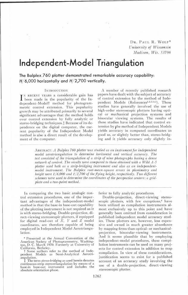
DR. PAUL R. WOLF*
University of Wisconsin
Madison, Wis. 53706
Independent-Model TriangulationThe Balplex 760 plotter demonstrated remarkable accuracy capability:H/6,OOO horizontally and H/2,700 vertically.
IKTRODUCTIOK
I K RECENT YEARS a considerable gain hasbeen made in the popularity of the In
dependent-Modelt method for photogrammetric control extension. This popularitygrowth may be attributed primarily to severalsignificant advantages that the method holdsover control extension by fully analytic orstereo-bridgi ng techniq ues. t Because of its dependence on the digital computer, the current popularity of the Independent Modelmethod is also a direct resul t of the development of the computer.
A number of recently published researchpapers have dealt with the subject of accuracyof control extension by the method of Independent Models (References1,2.3,4.5). Thesestudies have generally involved the use ofhigh-order stereoscopic plotters having opticalor mechanical projection systems andbinocular viewing systems. The results ofthese studies have indicated that control extension by the method of Independent Modelsyields accuracy in computed coordinates asgood as, or slightly better than, stereo-bridging and it yields accuracy only slightly in-
ABSTRACT: A Balplex 760 plotter was studied as an instrument for independentmodel aerotriangulation to determine horizontal and vertical accuracy. Thetest consisted of the triangulation of a strip of nine photographs having a densenetwork of control. The results were compared to those obtained with a Wild A-5plotter used both as a strip-bridging instrument and also as an independentmodel instrument. The Balplex root-mean-square errors in planimetry andheight were 1/6,000 and 1/2,700 of the flying height, respectively. Two differentschemes were used to determine the coordinates of the perspective centers: a gridplate and a two-point method.
I n comparing the two basic analogic control extension procedures, one of the important advantages of the independent-modelmethod is that the base-in base-out capabilityof the plotting instrument is not required as itis with stereo-bridging. Double-projection, direct-viewing stereoscopic plotters, if equippedfor digital read-out of X, Y and Z modelcoordinates, are therefore capable of beingemployed in I ndependent Model Aerotriangulation.
* Presented at the Annual Convention of theAmerican Society of Photogrammetry, Washington, D. C. March 1970. Formerly at University ofCalifornia, Berkeley.
t Some authors refer to the method of Independent Models as Semi-Analytical Aerotriangulation.
t The term stereo-bridging as used herein denotescontinuous-strip stereotriangulation by means of abase-in base-out instrument and includes theabsolute orientation phase.
ferior to fully analytic procedures.Double-projection, direct-viewing stereo
scopic plotters, with few exceptions,6 havebeen utilized as compilation instruments almost exclusively up to this point and havegenerally been omitted from consideration inpublished independent model accuracy studies. These plotters are, however, less expensive and owned in much greater abundanceby mapping firms than optical- or mechanicalprojection, binocular-viewing instruments.And it seems plausible that by employingindependent-model procedures, these compilation instruments can be used on many projects for control extension in addition to mapcompilation. In view of these considerations,justification seems to exist for a publishedaccount of an accuracy study involving theuse of a double-projection, direct-viewingstereoscopic plotter.
1262
INDEPENDENT-MODEL TRIA GULATION 1263
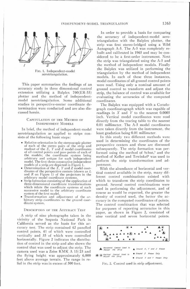
FIG. 2. Control used in strip adjustment.
® • @ • • A@• ••~... • • •• ... ... ® • .. ... • @
... '" It .........@... '" .. • @ .@
In order to provide a basis for comparingthe accuracy of independent-model aerotriangulation with the Balplex plotter, thestrip was first stereo-bridged using a WildAutograph A-5. The A-5 was completely rebuilt and calibrated in 1965 and may be considered to be a first-order instrumen t. Nextthe strip was triangulated using the A-5 andthe method of independent models. Finallythe Balplex was utilized in performing thetriangulation by the method of independentmodels. In each of these three instances,model coordinates of all ground control pointswere read. Using only a nominal amount ofground control to transform and adjust thestrip, the balance of control was available forevaluating the accuracies of the computedcoordinates.
The Balplex was equipped with a Coradograph coordinatograph which was capable ofreadings in X and Y to the nearest 0.0005inch. Vertical model coordinates were readdirectly from the tracing table to the nearest0.01 millimeter. The A-5 model coordinateswere taken directly from the instrument, theleast gradation being 0.01 millimeter.
I n this study two differen t methods wereused in determining the coordinates of theperspective centers and these are discussedsubsequently. The strip formation was performed using the method of Schut,7 and themethod of Keller and Tewinkel 8 was used toperform the strip transformation and adjustment.
With the abundance of horizontal and vertical control available in the strip, many different control combinations existed withwhich to transform the strip coordinates toground. Several control combinations wereused in performing the adjustment, and ofcourse as would be expected, the greater thedensity of control used, the better the accuracy in the computed coordinates of points.The control combination that was selectedfor purposes of reporting accuracies in thispaper, as shown in Figure 2, consisted ofnine vertical and seven horizontal points.
• Ground Z Known Only
... Ground X, Y and Z Known
• Ground X and Y Known Only
A.. Horuonfol Con/rol Us~d /0fA Adjust lhe Strip
CAPITULATION OF THE METHOD OF
INDEPENDENT MODELS
In brief, the method of independent-modelaerotriangulation as applied to strips consists of the following basic steps:
• Relative orientation in the stereoscopic plotterof each of the stereo pairs of the strip andreadout of the X, Y and Z model coordinatesof all control points and pass points of each ofthe models; the coordinate system beingarbitrary and unique for each independentmodel. The first three consecutive independentmodels of a strip are depicted in Figure 1.
• Determination of the X, Y and Z model coordinates of the perspective centers (shown as Land R on Figu re 1) of the projectors in thearbitrary model coordinate systems.
• Strip formation consisting of the application ofthree-dimensional coordinate transformationswhich relate the coordinate systems of eachsuccessive model to the arbitrary coordinatesystem of the first model.
• Transformation and adjustment of the arbitrary strip coordinates to the g-rOUl1d coordinate system.
This paper summarizes the findings of anaccuracy study in three dimensional controlextension utilizing a Balplex 760(ER-55)plotter and the method of independen tmodel aerotriangulation. Some additionalstudies in perspective-cen ter coordinate determination were conducted and are also discussed herein.
FIG. 1. Independent-modelaerotriangulation.
I
DESCRIPTION OF THE ACCURACY TEST
A strip of nine photographs taken in thevicinity of the Sequoia National Park inCalifornia served as the basis for this accuracy test. The strip contained 42 panelledcontrol points, 41 of which were controlledvertically and 35 of which were controlledhorizontally. Figure 2 indicates the distribution of con trol in the strip and also shows thecontrol that was used to adjust the strip. Thecamera used was a Zeiss RMK A 15/23 andthe flying heigh t was approximately 6,000feet above average terrain. The range in relief in the strip was in excess of 500 feet.
1264 l'HOTOGRAMMETRIC ENGINEERING
TABLE 1. AVERAGE ERRORS I PHOTOGRAMMETRIC CONTROL EXTENSION
Average Errors in Feet (H = 6,000')
In Control Usedfor AdjustmentMethod
X(a)
A-S Bridging 0.8A-S Ind. Models 0.6Balplex Jnd. Mod. 1.2
y(b)
0.60.61.0
Z(e)
0.60.90.9
In Control Not UsedIn All Control for Adjustment
X y Z X Y Z(d) (e) (f) (g) (h) (i)
0.9 0.7 0.9 0.9 0.7 1.00.7 0.6 0.9 0.7 0.6 1.00.9 0.9 1.7 0.9 0.9 1.9
Several different combinations of nine vertical and seven horizontal control points wereused and each yielded essentially the sameresults. Both the horizontal and verticalstrip adjustments were performed using thethird degree option of the aforementionedstrip adjustment method.
TEST RESULTS
The accuracies of the three separate aerotriangulations are summarized in Tables 1:lnd 2. In Table 1 average errors in feet in thecomputed X, Yand Z ground coordinates arelisted. The average errors are the means ofthe absolute values of the discrepancies between control coordinates and computedcoordinates. In columns a, band c are listedaverage errors for only those control pointsused to adjust the strip. Columns d, e and flist average errors for all control, includingthat used to adjust the strip. Finally columnsg, hand i list average errors for only the control which is in excess of that used to adjustthe strip. This latter average error is mostrevealing and should be of primary interest,because in aerotriangulation projects thesepoints exclusive of the control used in stripadj ustment are the unknowns that are sough t.
Table 2 lists root-mean-square errors 111
feet in the computed X, Y and Z ground
coordinates. In col umns a, band c are therms errors for only that control used to adjust the strip. Columns d, e and f list the fmserrors for all control and columns g, hand icontain the fms errors for only the excesscon trol.
The resul ts of this one test, of course,could not be considered conclusive enough toenable the drawing of firm conclusions. However, this test does indicate the following:
* The methods of stereo-bridging and independent models yield approximately the sameaccuracy which is in agreement with publishedfindings of others.
* Both methods yield higher accuracy inplanimetric coordinates than in the Z-coordinate which of course is expected.
* Although the first-order plotter yields thehigher accuracy of the two instruments, theBalplex shows a capability for quite remarkable accuracy.
Considering columns g, hand i of Table 1,it is seen that the average error with theBalplex was approximately 1/6,700 of theflying height for computed planimetric coordinates and approximately 1/3,100 of theflying height for computed vertical coordinates. In Table 2, columns g, hand i indicatethat with the Balplex, root-mean-square errors 111 computed planimetric coordinateswere approximately 1/6,000 and 1/2,700
TABLE 2. ROOT-MEAN-SQUARE ERRORS IN PHOTOGRAMMETRIC CONTROL EXTENSION
Root Mean Square Errors in Feet (H = 6,000')
In Control UsedIn All Control
In Control Not UsedMethod for Adjustment for Adjustment
X y Z X Y Z X Y Z(a) (b) (e) (d) (e) (f) (g) (h) (i)
A-S Bridging 1.1 0.8 0.8 1.1 0.8 1.1 1.1 0.8 1.2A-S Ind. Models 0.7 0.7 1.2 0.9 0.8 1.2 0.9 0.8 1.2Balplex Ind. Mod. 1.0 1.0 1.0 1.1 1.1 2.0 1.0 1.0 2.2
INDEPENDE 'T-MODEL TRIANGULATION
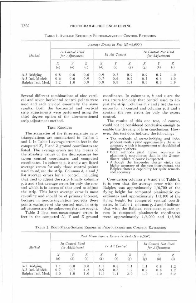
X r _p rmt/x-x,)+fTj/Y-Y,)+m,,(Z-Z,J]Cm,,.(x-Jr;)+ m,z{Y- i[J+m,,(Z-z,)
)' , _p rmil (X-XJ+mu (Y-Yi)+mu(z-z,J][""m" (X-X,) +mg (Y-rJ+m,., (Z-z,. J
FIC. 3. Grid-plate method for determining the coordinates of the perspective center.
1265
of the flying height, respectively. From theseresults it seems evident that double-projection, direct-viewing plotters are capable ofsatisfactory accuracy in control extension formany mapping projects. For certain compilation projects where the full C-factor capability of the Balplex is to be utilized, thisvertical control accuracy must be consideredborderline.
DETERMIN AnON OF PERSPECTIVE
CENTER COORDINATES
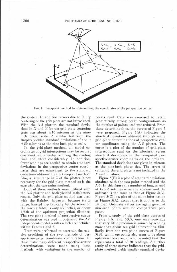
As a part of this study, two differentmethods for determining perspective centercoordinates were investigated. The firstmethod, illustrated in Figure 3, was used onboth the A-S and Bal plex and consisted ofusing a precise grid plate.' I n this method, thegrid plate was inserted into each projectorand the X, Y, and Z model coordinates weremonocularily read for a number of grid intersections. Treating the projector principal distance as analogous to the camera focal length,and considering the precise coordinates of thegrid intersections and their respective modelcoordinates as analogous to photo coordinates and ground control coordinates respectively, the space resection problem wassolved. The basic and well known collineari tyequations which are solved in the resection aregiven in Figure 3. The solution provided theX, Y and Z coordinates of the perspectivecenters in the model system and in additionit yielded the orientation angleE. A minimumof three intersections must be read for a
solution, but the four corner points are recommended as a practical minimum. A greaternumber of redundant readings provides statistically improved results.
The second method for the coordinates ofthe perspective center, depicted in Figure 4,did not require a grid plate but rather itutilized the diapoEitives of the models themselves. 9 The method consisted of monocularily reading the X and Y model coordinateEof random image points at two or more different Z settings which were as widely spacedas possible. The two-point form of the equation for a straight line, given in Figure 4,was then applied to calculate the perspectivecenter coordinates.
In the two-point equation, XL, YL andZL are the model coordinates of the perspective center, Xl, YI and Zl are the model coordinates at the first Z setting, and X 2, Y2
and Z2 are the model coordinates at the second Z setting. A minimum of two differentpoints each read at two Z settings is requiredfor a solution; however, four corner pointsare again recommended as a practical minimum and more redundancy improves theresul ts.
Both methods have advantages and disadvantages. In the two-point method an expensive precise grid plate is not needed andfurthermore the added operation of placingthe grid plate in the projectors is eliminated.The data processing with the two-pointmethod is somewhat simplified also, as gridplate coordinates need not be introduced into
1266 PHOTOGRAMMETRIC ENGINEERING
FIG. 4. Two-point method for determining the coordinates of the perspective center.
the system. In addition, errors due to faultycentering of the grid plate are not introduced.With the A-S plotter, the standard deviations in X and Y for ten grid-plate centeringtests was about ± 10 microns at the nineinch photo scale. A similar test with theBalplex yielded standard deviations of about±50 microns at the nine-inch photo scale.
In the grid-plate method, all model coordinates of grid intersections may be read atone Z-setting, thereby reducing the readingtime and effort considerably. In addition,fewer readings are needed to obtain standarddeviations in the perspective center coordinates that are equivalent to the standarddeviations obtained by the two-point method.Also, a large range in Z of the plotter is notnecessary for the grid plate method as is thecase with the two-point method.
Both of these methods were utilized withthe A-S plotter and both yielded satisfactoryresul ts. Only the grid-plate method was usedwith the Balplex, however, because its Zrange, limited mechanically by the screw onthe tracing table, is only six inches, or aboutl/Sth of the optimum projection distance.The two-point method of perspective centerdetermination was used in obtaining the A-Sindependent-model results which are includedwithin Tables 1 and 2.
Tests were performed to ascertain the relative precisions of the two methods of perspective-center coordinate computation. Inthese tests, many different perspective-centerdeterminations were made using bothmethods, with variations in the number of
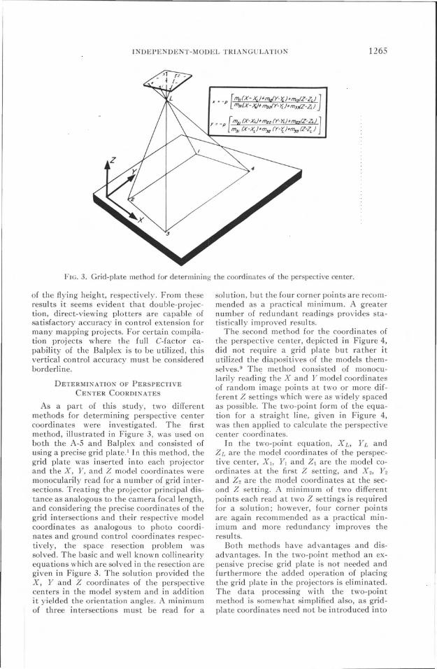
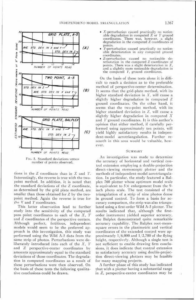
points read. Care was exercised to retaingeometically strong point configurations asthe number of points used was reduced. Fromthese determinations, the curves of Figure 5were prepared. Figure SeA) indicates thestandard deviations obtained through manygrid-plate determinations of perspective center coordinates using the A-S plotter. Thecurve is a plot of the number of grid-plateintersections read on the abscissa, versusstandard deviations in the computed perspective-center coordinates on the ordinate.The standard deviations are given in micronsat the nine-inch photo size. The errors ofcentering the grid plate is not included in theX and Yvalues.
Figure S(B) is a plot of standard deviationsob tai ned wi th the two-poin t method and theA-S. In this figure the number of images readat two Z settings is on the abscissa and theordinate is the same as that of Figure SeA).Figure S(C) is a plot of the same informationas Figure SeA), except that it applies to theBalplex. Ordinate values are again given atnine-inch photo size for comparative purposes.
From a study of the grid-plate curves ofFigure SeA) and 5(C), one may concludethat very little precision is gained by readingmore than about ten grid intersections. Similarily from the two-point curves of Figure5(B), ten image points also seem to be aboutoptimum; however, it is to be noted that thisrepresents a total of 20 readings. A furtherstudy of these curves indicates that the gridplate method yields smaller standard devia-
INDEPEKDEN'!'-l\10DEL TRIANGULATION 1267
lions in the Z coordinate than in X and Y.Interestingly, the reverse is true with the twopoint method. In addition, it is noted thatthe standard deviations of the Z coordinate,as determined by the grid plate method, aresmaller than those obtained for Z by the twopoint method. Again the reverse is true forthp, ~ and Y coordinates.
This latter observation lead to furtherstudy into the sensitivity of the computedpass point coordinates to each of the X, Yand Z coordinates of the perspective centers.Although perfect, fictitious, independentmodels would seem to be the preferred approach in this investigation, this study wasperformed using the Wild A-S data from thesame strip of photos. Perturbations were deliberately introduced into each of the X, Yand Z perspective-center coordinates byamounts approximately equal to the standarddeviations of those coordinates. The degradation in computed coordinates as a result ofthese perturbations were then observed. Onthe basis of these tests the following qualitative conclusions could be drawn.
• X-perturbation caused practically no noticeable degradation in computed X or Y groundcoordinates. There was, however, a slightdegradation in the computed Z coordinates ofpoints.
• Y-perturbation caused practically no noticeable deterioration in any computed groundcoordinates.
• Z-perturbation caused no noticeable deterioration in the computed Z coordinates ofpoints. There was a slight deterioration in X,and a slightly more noticeable degradation inthe computed Y, ground coordinates.
On the basis of these tests alone it is difficuI t to reach a decision as to the preferablemethod of perspective-center determination.It seems that the grid-plate method, with itshigher standard deviation in X, will cause aslightly higher degradation in computed Zground coordinates. On the other hand, itseems that the two-point method, with itshigher standard deviation in Z, will cause aslightly higher degradation in computed Xand Y ground coordinates. It is this author'sopinion that either method, if carefully performed using approximately ten points, willyield highly satisfactory resul ts in independent-model aerotriangulation. Further reEearch in this area would be valuable, ho\\"ever.
SUMMARY
An investigation was made to determinethe accuracy of horizontal and vertical control extension employing a double-projectiondirect-viewing stereoscopic plotter and themethods of independent-model aerotriangulation. In particular, the study featured a Balplex 760 plotter whose optimum model scaleis equivalent to S X enlargement from the 9inch photo scale. The test consisted of thetriangulation of a strip of nine photos densein ground control. To form a basis for accuracy comparison, the strip was also triangulated using a first-order Wild A-S plotter. Theresults indicated that, although the firstorder instrument yielded superior accuracy,the Balplex demonstrated quite remarkableaccuracy capability. The Balplex root-meansquare errors in the planimetric and verticalcoordinates of the extended control were approximately 1/6,000 and 1/2,700 of the flyingheight, respectively. Although a single test isnot sufficient to enable drawing firm conclusions, it does indicate that control extensionto satisfactory accuracy using double-projection direct-viewing plotters may be feasiblefor many mapping projects.
A further phase of this study has indicatedthat with a plotter having a substantial rangein Z, perspective-center coordinates may be
(C)
fA)
(8)
O......-t--+--+_-+_~-J
FIG. 5. Standard deviations versusnumber of points observed.
O......-t6-~8~-~-~--:1:--JNUMBER OF
~!!:<E~ 30'f'lIl:~-'_--~- "
2°1-r---==i"'-+-;;;;;;;;~r=*=;;;tI AVE
~ 10'F-!...;;;;;;=t::::~~~:~~~~ I0, O"--:~-+---f.;--+--~:--It; 6 t:J I':; /2 /4
NUMBER OF POINTS READ
1268 PHOTOGRAMMETRIC ENGINEERING
determined to satisfactory accuracy by employing either a grid-plate or a two-pointmethod. No definite preference in methodscould be established, although both methodspossess certain advantages and disadvantages. With either method, the optimum number of points that should be read seemed to beapproximately ten; the practical minimum isfour corner points. If care is exercised, eithermethod should yield highly satisfactory results in independent-model aerotriangulation.
Although this project was conducted without the aid of encoders for automatic, directrecording of model coordinates, such equipment is definitely recommended for utmostefficiency in independent-model aerotriangulation.
ACKNOWLEDGMEKTS
The author gratefully acknowledges thecooperation on this project of the photogrammetry section of the California Division ofHighways for providing the photography andground control data for this study. Gratefulacknowledgment is also due the photogrammetry section of the Pacific Region of theU. S. Geological Survey for preparation of theBalplex diapositives and the use of other oftheir equipment. Special thanks are also dueto Prof. Francis H. Moffitt of the Universityof California for his assistance on this projectand to Mr. Michael Thomas, photogrammetry student at the Uni\'ersity of Califor-
nia, who assisted with much of the data processing.
1. Tnghilleri, G. and Galetto, R., "Further Developments of the Method of Aerotriangulation byIndependent Models," Photogrammetria, Vol.22, No.1, pp. 13-28, January 1967.
2. Shmutter, B., "Triangulation with IndependentModels," Photogrammetric Engineering, Vol.XXXV, No.6, pp. 548-553, June 1969.
3. Weissman, S., "Semi-Analytical Aerotriangulation," Photogrammetric Engineering, Vol.XXXV, No.8, pp. 789-795, August 1969.
4. Wong, K., "Computer Programs for StripAerotriangulation," Journal of the Surveyingand Mapping Division, Proceedings of the A merican Society of Civil Engineers, Vol. 95, No. SUI,pp. 71-80, October 1969.
5. Thompson, E. H., "Aerial Triang-ulation andthe Thompson Watts Plotter," A paper published at the University College London, Lon·don, England, July 1964.
6. Altenhofen, R. E., "Semianalytical Aerotnangulation in Quadrangle Mapping," Proceedings of the 34th Annual Meeting, the AmericanSociety of Photogrammetry, pp. 5-27, \·Vashington, D. C., March 1968.
7. Schut, G. H., "Formation of Strips from Independent Models," Report AP-PR 36, National Research Council of Canada, Ottawa,July 1967.
8. Keller, M. and Tewinkel, G. C., "Aerotriangulation Strip Adjustment," Technical Bulletin No.23, U. S. Dept. of Commerce, Coast andGeodetic Survey, Washington, D. C., August1964.
9. Ligterink, G. H., "Aerial Triangulation byIndependent Models, the Coordinates of thePerspective Center and Their Accuracy," Apaper published at the Technological University,Delft, Xetherlands, February 1969.
Notice to Contributors
1. Manuscripts should be typed, double-spaced on 8! X 11 or 8 X 10!white bond, on one side only. References, footnotes, captions-everythingshould be double-spaced. Marginsshould be I! inches.
2. Two copies (the original and firstcarbon) of the complete manuscriptand two sets of illustrations shouldbe submitted. The second set of illustrations need not be prime quality.
3. Each article should include an abstract, which is a digest of the article.An abstract should be 100 to 150words in length.
4. Tables should be designed to fit intoa width no more than five inches.
5. Illustrations should not be more thantwice the final print size: glossyprints of photos should be submitted.Lettering should be neat, and designed for the reduction anticipated.Please include a separate list of captions.
6. Formulas should be expressed assimply as possible, keeping in mindthe difficulties and limitations encountered in setting type.
Copyright © 2022 FDOKUMEN