In vitro irradiation station for broad beam radiobiological experiments
21
1 In vitro irradiation station for broad beam radiobiological experiments A.-C. Wéra 1 , H. Riquier 2 , A.-C. Heuskin 1 , C. Michiels 2 , S. Lucas 1 1 NAmur Research Institute for LIfe Sciences (NARILIS), Research Centre for the Physics of Matter and Radiation (PMR), University of Namur-FUNDP, Corresponding author: [email protected] 2 NAmur Research Institute for LIfe Sciences (NARILIS), Unité de Recherche de Biologie Cellulaire (URBC), University of Namur-FUNDP Rue de Bruxelles, 61, B-5000 Namur, Belgium Abstract The study of the interaction of charged particles with living matter is of prime importance to the fields of radiotherapy, radioprotection and space radiobiology. Particle accelerators and their associated equipment are proven to be helpful tools in performing basic science in all of these fields. Indeed, they can accelerate virtually any ions to a given energy and flux and let them interact with living matter either in vivo or in vitro. In this context, the University of Namur has developed a broad beam in vitro irradiation station for use in radiobiological experiments. Cells are handled in GLP conditions and can be irradiated at various fluxes with ions ranging from hydrogen to carbon. The station is mounted on a 2 MV Tandem accelerator, and the energy range can be set up in the LET ranges that are useful for radiobiological experiments. This paper describes the current status of the hardware that has been developed, and presents results related to its performance in term of dose-rate, energy range and beam uniformity for
Transcript of In vitro irradiation station for broad beam radiobiological experiments

1
In vitro irradiation station for broad beam radiobiological experiments
A.-C. Wéra1, H. Riquier
2, A.-C. Heuskin
1, C. Michiels
2, S. Lucas
1
1 NAmur Research Institute for LIfe Sciences (NARILIS),
Research Centre for the Physics of
Matter and Radiation (PMR), University of Namur-FUNDP,
Corresponding author: [email protected]
2 NAmur Research Institute for LIfe Sciences (NARILIS),
Unité de Recherche de Biologie
Cellulaire (URBC), University of Namur-FUNDP
Rue de Bruxelles, 61, B-5000 Namur, Belgium
Abstract
The study of the interaction of charged particles with living matter is of prime importance to the
fields of radiotherapy, radioprotection and space radiobiology.
Particle accelerators and their associated equipment are proven to be helpful tools in performing
basic science in all of these fields. Indeed, they can accelerate virtually any ions to a given energy
and flux and let them interact with living matter either in vivo or in vitro.
In this context, the University of Namur has developed a broad beam in vitro irradiation station
for use in radiobiological experiments. Cells are handled in GLP conditions and can be irradiated
at various fluxes with ions ranging from hydrogen to carbon. The station is mounted on a 2 MV
Tandem accelerator, and the energy range can be set up in the LET ranges that are useful for
radiobiological experiments.
This paper describes the current status of the hardware that has been developed, and presents
results related to its performance in term of dose-rate, energy range and beam uniformity for

2
protons, alpha particles and carbon ions. The results of clonogenic assays of A549 lung
adenocarcinoma cells irradiated with protons and alpha particles are also presented and compared
with literature.

3
Introduction
Since 1946, with the proposal of R. R. Wilson [1], the use of charged particles in radiobiology
has encountered an increasing interest. The development of cancer treatments using particle
accelerators has continued to this day. In 2005, U. Amaldi found that more than 40% of the
17,500 existing particle accelerators were used for radiotherapy, with about 40,000 and 2,200
patients treated with proton beams and carbon ions respectively [2]. At the same time,
fundamental research performed with particle accelerators was yielding useful information for
medical applications as well as for radioprotection and space radiobiology [3-8]. The strength of
a particle accelerator lies in its wide range of available ions for which energies and flux can be
greatly varied. There are two configurations: microbeams and broad beams. On the one hand,
micro/nano-beams allow the irradiation of a selected cell, or a portion of a cell, with a precise
number of ions [9-16]. However, microbeam installation requires tedious developments for cell
recognition, alignment and beam scanning. On the other hand, broad beams are easier to
implement [17-22]. Furthermore, this system also allows simultaneous treatment of thousands of
cells within minutes. Therefore, with broad beams, additional stresses like temperature effects or
absence of culture medium during irradiation can be minimized. Nevertheless, as is the case for
patient irradiation, not all the cells can be targeted because of the Poisson distribution of the
beam.
In 2007, the LARN laboratory at the University of Namur started to develop an inexpensive
broad beam in vitro irradiation station. First results were published in 2008 regarding proton
beam characterization [23]. In this paper, we describe the hardware development for our
irradiation station, as well as present results related to its performance in term of energy

4
straggling, beam uniformity and monitoring for proton, alpha and carbon ions beams. The
irradiation station was used to irradiate A549 non-small-cell lung cancer adenocarcinoma cells
(NSCLC) with proton and alpha beams at 1 Gy/min. The survival fraction curves assessed by
conventional clonogenic assays are compared to literature. Radiosensitivity parameters, as well as
the inactivation cross-section, are calculated.
Material and Methods
I. Irradiation facility
The irradiation station is placed on the 2 MV Tandem accelerator (High Voltage Engineering
Europa) available at the LARN laboratory. Thanks to its dual source, particles from Hydrogen to
Uranium can be accelerated with a terminal voltage adjustable from 0.15 to 2 MV. The
irradiation station is fixed at the end of the 10° exit port of the switching magnet. The irradiation
field is set up by defocusing the beam with the help of electrostatic and magnetic optical elements
mounted along the beam line. The irradiation station is schematically presented in Figure 1. It
consists of a vacuum chamber (2) in which a removable CCD camera is mounted with a BC400
scintillator (4). The camera is used to tune the beam at a high current. The beam is extracted to air
through an exit window (6) made of a 8 µm Kapton foil maintained between two stainless steel
cylinders (see insert of Figure 1). A collimated PIPS (Passivated Implanted Planar Silicon)
detector is placed just before the irradiation head (5). This detector intercepts the left side of the
beam and is used as a dose-rate monitor during the irradiation. Another PIPS detector (7) is fixed
on an XY table, which is activated by a step motor (8) and which is placed just after the exit

5
window. The exposed surface of this detector was limited with a collimator (Ø 510 ± 2 µm). This
is used to adjust the dose-rate, and to assess the stability and the homogeneity of the broad beam.
II. Dosimetry
The dose-rate is given by:
)1((g/cm³)
s)(part/cm²..(keV/µm)10x6.1(Gy/s) 9
LET
D
where LET is the linear energy transfer, Φ is the flux and ρ is the cell density. Therefore, to
perform radiobiological studies with a broad beam, the LET and the flux need to be known and
constant over the entire surface covered by the biological cells and throughout the irradiation.
As the LET is related to the beam energy, a precise energy calibration of the accelerator is
necessary. The experimental detail and results of the calibration were presented in [24]. The LET
value, calculated by the SRIM program [25], can be scanned from 10 to 50 keV/µm for proton
and from 90 to 200 keV/µm for alpha particles with energies ranging from 4 MeV to 800 keV
and from 6 MeV to 3 MeV for proton and alpha particles respectively. For carbon ions, the
Kapton exit foil is replaced by a 3 µm Mylar foil, and LET from 650 to 900 keV/µm are
achievable.
The flux can be adapted to obtain a large range of dose-rates (typically from 0.1 to 10 Gy/min).
Its stability is checked over time and over the irradiation surface. The beam uniformity is checked
by moving the PIPS millimeter by millimeter to obtain a 1 x 1 cm map. The results presented in
this paper were obtained for a fixed dose-rate of 1 Gy/min for all ions (1H
+,
4He
2+,
12C
4+).

6
III. Cell culture and irradiation
Human A549 NSCLC cells were grown in MEM (Minimum Essential Medium) (Invitrogen, UK)
containing 10% (v:v) fetal calf serum (FCS) (Invitrogen, UK). Twenty-four hours before
irradiation, 100,000 cells were seeded as a 35 µl drop at the centre of the Kapton foil (exit
window) of pre-sterilized irradiation heads (see figure 1). These heads are then closed with a
plastic cap to avoid dehydration and contamination and are placed in an incubator at 37°C with
5% CO2. Six hours after seeding, the drop is rinsed twice with phosphate-buffered saline pH 7.4
(10 mM phosphate, 0.9 % NaCl) (PBS) to remove non-adherent cells. The irradiation heads are
then filled with culture medium and replaced in the incubator. Just before the irradiation, the
culture medium is replaced by independent CO2 medium. After the irradiation, the CO2 medium
is poured off and the irradiation heads are rinsed with PBS. The plastic cap is then removed, and
a sterile cotton swab is used to take away the cells that may have detached from the central drop
and diffused outside the irradiated field. The plastic cap is replaced on the irradiation heads for
another PBS wash. Cells are detached by using trypsin, then counted and seeded in 6-well plates
(9.40 cm²) at desired concentrations. Cells are also seeded in a separated dish at one
concentration per dose and 2 hours later the cells are fixed with paraformaldehyde (PFA) 4% for
10 minutes before 3 PBS washes. The number of cells attached to the dish is counted manually
under an optical microscope to precisely know the number of cells seeded for each concentration
and dose. Eleven days post irradiation, the number of visible colonies (containing more than 50
cells) is counted after staining with crystal violet in 2% ethanol. The plating efficiency (PE) is
determined for each dose and the survival fraction is calculated by evaluating the ratio of the PE
for the irradiated cells to the PE for the control cells. At least three independent experiments are
7
performed for each dose and the errors are evaluated as a standard deviation. Note that the control
cells underwent exactly the same steps as the irradiated cells. In this study, the LET values were
chosen to obtain the maximum relative biological effectiveness (RBE), which corresponds to
~100 keV/µm and ~25 keV/µm for alpha and proton respectively [20]. The dose-rate was fixed to
1 Gy/min.
Results and Discussion
I. Beam characterization
Energy spread
In order to determine the dose-rate error, the energy straggling need to be determined at the cell
entrance (i.e. after the 8 µm Kapton foil). For that purpose, a calibrated PIPS detector was placed
in the vacuum chamber and the energy spectra were recorded with and without the Kapton foil.
The experiments were performed for proton and alpha particles for energies ranging from 0.7 to
3.8 MeV and from 4.5 to 5.9 MeV, respectively. The results presented in Figure 2 were obtained
for the 1.2 MeV proton beam. Without the Kapton foil, the energy spread characterized by the
full width at half maximum (FWHM) was 7 keV at 1.2 MeV incident energy. With the Kapton
foil, the FWHM increased to 25 keV and the energy peaked at 952 keV. This energy straggling
induced LET variations (ΔLET) estimated at 2% at the cell mid-thickness, using the SRIM
program. This variation is equal to 1% for the 5.3 MeV alpha beam. The same experiments were
performed for carbon ions with energies ranging from 5.4 to 10 MeV and with a 3 µm Mylar foil
as the exit window. Without the Mylar foil, the FWHM at 10 MeV was 70.7 keV; it increased to
192 keV at 7.60 MeV with the Mylar foil. This induced LET variation of less than 1% at both cell

8
entrance and cell mid-thickness. In conclusion, the LET (ΔLET) variations induced by the exit
window and the passage through half of the cell layer are limited to less than 2% for the three
beams.
Dose-rate stability and online monitoring
The beam stability was checked using a collimated PIPS detector placed in front of the incident
beam. In Figure 3, we can observe the excellent stability (± 2.8 %) of the 5.3 MeV alpha beam,
for which the dose-rate was set to 1 Gy/min with a LET of 100 keV/µm at the cell entrance.
During irradiation, the dose-rate is monitored with another PIPS detector fixed on the left side of
the beam. Indeed, we observed that the ratio between the number of particles detected in the
centre of the beam to the one counted at the left side of the beam remains constant, even if the
flux of the incident particle is modified. Data taken over more than one hour allowed to perform a
linear fit of the ratio in function of time. This showed an angular coefficient lower than 5 10-6
s-1
even if the flux of incident particles detected in the centre of the beam decreased by more than
30% during this time. The reliability of this system allowed the control of the dose-rate during
the irradiation.
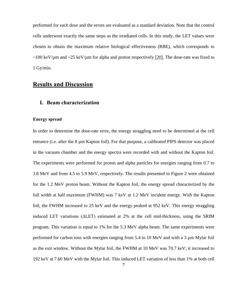
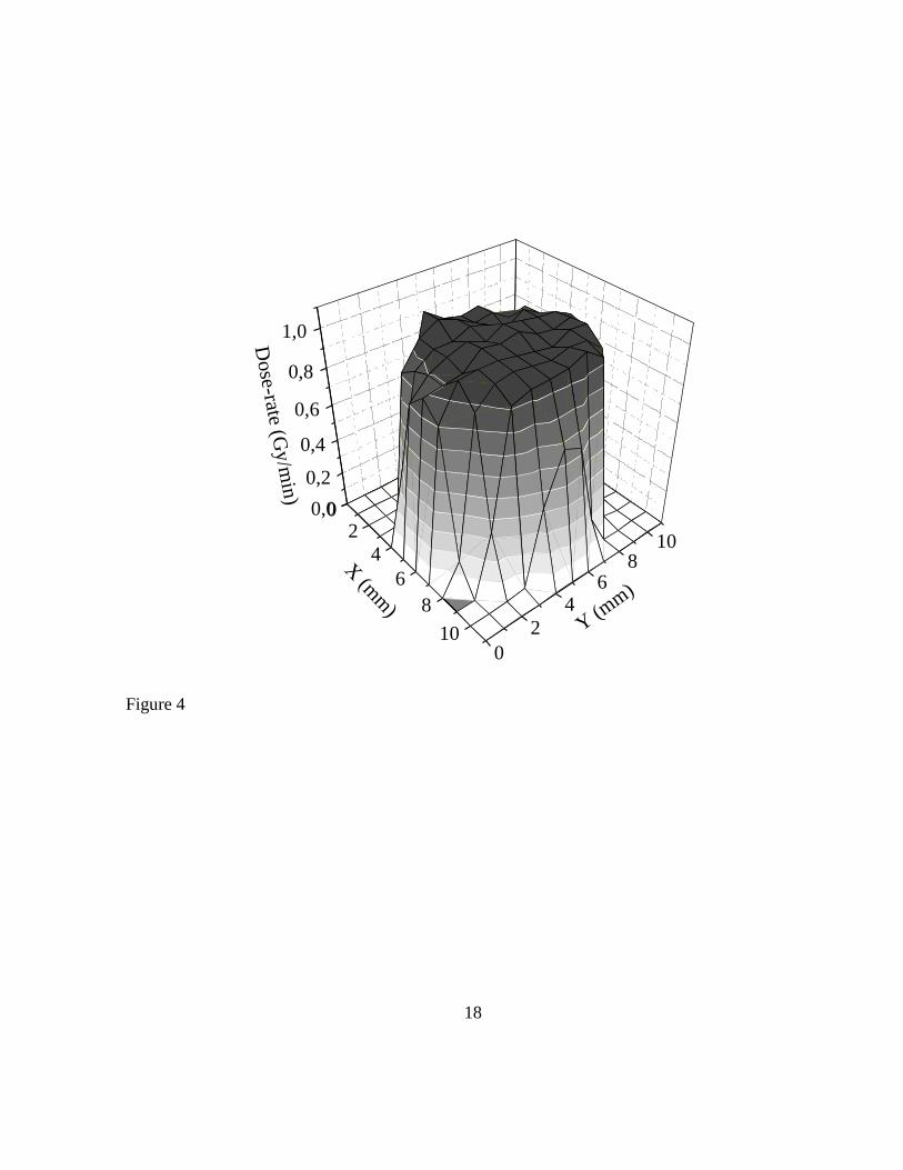
Beam spatial uniformity
The beam homogeneity was checked before each irradiation using a collimated (Ø 510 µm) PIPS
detector mounted on an XY table. The flux of incident particles (Φ) is measured over a surface of
10 x 10 mm by a one millimeter step. Figure 4 presents the results obtained for a 5.3 MeV alpha
beam at a dose-rate of 1 Gy/min. With our setup, an irradiation field of 6 x 5 mm with a dose-rate
variation lower than 10 % can be selected. That value includes the 2.8% beam current variation

9
calculated above. Similar results are obtained for the proton beam. For carbon ions, a 3 µm Mylar
foil is used as exit window.
II. Induced dose-rate error
The dose-rate error DΔ during a typical experiment can be estimated according to the following
formula if the density of target is 1 g/cm³:
)2(ΔΦ)LETΔLET(Φ101.6ΔΦΦ
DΔLET
LET
DDΔ 9
where ΔLET and ΔΦ are respectively the LET and the flux variation evaluated at the cell mid-
thickness. The LET variations (ΔLET) induced by energy straggling are 0.5 keV/µm for the
proton beam, 1 keV/µm for the alpha beam and 2 keV/µm for carbon ions. The flux variations
(ΔΦ) due to non-uniformity of the beam are ± 5 % for proton, alpha and carbon. According to
(2), DΔ is 0.07 Gy/min, 0.06 Gy/min and 0.05 Gy/min for the 1.2 MeV proton beam, 5.3 MeV
alpha beam and 10.0 MeV carbon beam respectively. A large part of the dose-rate error (70%) is
due to the heterogeneity of the beam.
III. Survival fraction
We present here the results of the A549 NSCLC survival curve measured for proton and alpha
particles at 1 Gy/min. The LET values at cell mid-thickness were equal to 25.5 and 102 keV/µm.
The survival fraction was assessed after clonogenic assays performed 11 days post-irradiation.
Results are presented in Figure 5 for the alpha and in Figure 6 for the proton beams. In these
figures, one can recognize the characteristic shape obtained with high LET irradiation: the
experimental data can be fitted with a linear model. This yields a radiosensitivity parameter α

10
(Gy-1
) equal to1.26 ± 0.03 Gy-1
and 2.36 ± 0.08 Gy-1
for proton and alpha particles respectively.
This parameter computes the characteristic intrinsic radiosensitivity of the cell type and the direct
mortality of the ionizing particle. We also used these values to calculate the inactivation cross
section of A549 NSCLC when exposed to proton and alpha particles according to the equation:
(3)(µm²)16.0 LET
This yields 5.1 µm² for proton and 38 µm² for alpha particles. The cross section increases by a
factor of 7.4 when moving from protons to alpha particles, whereas the LET increases by a factor
of 4. In Figure 7, we compare the results presented by Bromley et al. [26] for the same cell line
with X-ray irradiation to the results of our study. Bromley et al. obtained the characteristic shape
for survival fraction due to low ionizing radiation with radiosensitivity parameters equal to
0.2432 Gy-1
and 0.0257 Gy-2
for α and β respectively. The survival fraction at 2 Gy is equal to
0.55 for x-rays and to 0.057 ± 0.019 and 0.0068 ± 0.0018 for proton and alpha particles
respectively. The relative biological effectiveness (RBE) for a survival fraction of 0.10 is
estimated at 3.2 for the proton beam and 5.9 for alpha beam. In their work, Scampoli et al.
obtained similar results for Chinese hamster lung cells V79 [22]. They calculated a RBE equal to
4.7 for 34 keV/µm proton beam and 6.3 for 107 keV/µm alpha particles.
Conclusion
The in vitro irradiation station developed in our lab allows the irradiation of adherent cells with
proton, alpha and carbon broad beams. The dose-rate error has been evaluated and has not
exceeded 7% for all three types of beam. This system allows us to irradiate 100,000 cells
simultaneously, and can be used to perform radiobiological experiments like clonogenic assays,
immunofluorescence stainings, RNA extraction for gene expression study, morphological

11
assessment, and more. In this paper, we present the result of the survival fraction of A549
NSCLC irradiated with proton and alpha beams at 1 Gy/min. For both irradiations the LET with
the maximum RBE was chosen (25 and 100 keV/µm). The radiosensitivity parameter was
estimated to 1.26 ± 0.03 Gy-1
and 2.36 ± 0.08 Gy-1
for proton and alpha particles respectively.
The inactivation cross section was also calculated, and this highlighted the higher cell sensitivity
when working with alpha particles. The RBE was also derived from X-rays value of the literature
and is 3.2 and 5.9 for protons and alpha particles respectively.
Acknowledgements
We would like to thank Y. Morciaux, A. Nonet and L. Lambotte for their technical support. A.-C.
Heuskin is supported by the Belgian Found for Scientific Research (F.R.S. – FNRS). H. Riquier
is recipient of a Télévie fellowship.

12
References
[1] R.R. Wilson, Radiological use of fast protons, Radiology, 47 (1946) 487-491.
[2] U. Amaldi, Nuclear physics applications in diagnostics and cancer therapy, Nuclear Physics
A, 751 (2005) 409c-428c.
[3] E.A. Blakely, New measurements for hadrontherapy and space radiation: biology, Phys Med,
17 Suppl 1 (2001) 50-58.
[4] G. Chuanling, Studies of advantages of heavy ions in radiotherapy compared with gamma-
rays, Nuclear Instruments & Methods in Physics Research Section B-Beam Interactions with
Materials and Atoms, 259 (2007) 997-1003.
[5] Y. Furusawa, M. Aoki, M. Durante, Simultaneous exposure of mammalian cells to heavy ions
and X-rays, Adv Space Res, 30 (2002) 877-884.
[6] C.R. Geard, C.Y. Chen, Micronuclei and clonogenicity following low- and high-dose-rate
gamma irradiation of normal human fibroblasts, Radiation research, 124 (1990) S56-61.
[7] K.M. Prise, G. Schettino, C. Shao, V. Stewart, L. Wu, N. Zyuzikov, M. Folkard, B.D.
Michael, Studies of bystander responses with the GCI microbeams, Radiation research, 161
(2004) 118-119.
[8] H. Zhou, G. Randers-Pehrson, E.J. Hall, D.J. Brenner, C. Geard, T.K. Hei, Interaction of
radiation-induced adaptive response and bystander mutagenesis in mammalian cells, Radiation
research, 161 (2004) 115-115.
[9] P. Barberet, A. Balana, S. Incerti, C. Michelet-Habchi, P. Moretto, T. Pouthier, Development
of a focused charged particle microbeam for the irradiation of individual cells, Review of
Scientific Instruments, 76 (2005) -.
[10] M. Cholewa, B.E. Fischer, M. Heiss, Preparatory experiments for a single ion hit facility at
GSI, Nuclear Instruments & Methods in Physics Research Section B-Beam Interactions with
Materials and Atoms, 210 (2003) 296-301.
[11] M. Folkard, B. Vojnovic, K.M. Prise, A.G. Bowey, R.J. Locke, G. Schettino, B.D. Michael,
A charged-particle microbeam: I. Development of an experimental system for targeting cells
individually with counted particles, International journal of radiation biology, 72 (1997) 375-385.
[12] K.D. Greif, H.J. Brede, D. Frankenberg, U. Giesen, The PTB single ion microbeam for
irradiation of living cells, Nuclear Instruments & Methods in Physics Research Section B-Beam
Interactions with Materials and Atoms, 217 (2004) 505-512.
[13] M. Oikawa, T. Kamiya, M. Fukuda, S. Okumura, H. Inoue, S. Masuno, S. Umemiya, Y.
Oshiyama, Y. Taira, Design of a focusing high-energy heavy ion microbeam system at the JAERI
AVF cyclotron, Nuclear Instruments & Methods in Physics Research Section B-Beam
Interactions with Materials and Atoms, 210 (2003) 54-58.
[14] G. Randers-Pehrson, C.R. Geard, G. Johnson, C.D. Elliston, D.J. Brenner, The Columbia
University single-ion microbeam, Radiation research, 156 (2001) 210-214.
[15] T. Reinert, A. Fiedler, J. Skopek, J. Tanner, J. Vogt, T. Butz, Single ion bombardment of
living cells at LIPSION, Nuclear Instruments & Methods in Physics Research Section B-Beam
Interactions with Materials and Atoms, 219-20 (2004) 77-81.
[16] H. Yamaguchi, Y. Sato, H. Imaseki, N. Yasuda, T. Hamano, Y. Furusawa, M. Suzuki, T.
Ishikawa, T. Mori, K. Matsumoto, T. Konishi, M. Yukawa, F. Soga, Single particle irradiation

13
system to cell (SPICE) at NIRS, Nuclear Instruments & Methods in Physics Research Section B-
Beam Interactions with Materials and Atoms, 210 (2003) 292-295.
[17] I. Bailly, C. Champion, P. Massiot, P. Savarin, J.L. Poncy, S. Crespin, G. Alloy, V. Jacob, E.
Petibon, Development of an experimental system for biological studies: Scintillation and solid-
track detectors as dose monitors, Nuclear Instruments & Methods in Physics Research Section B-
Beam Interactions with Materials and Atoms, 187 (2002) 137-148.
[18] M. Belli, R. Cherubini, G. Galeazzi, S. Mazzucato, G. Moschini, O. Sapora, G. Simone,
M.A. Tabocchini, Proton Irradiation Facility for Radiobiological Studies at a 7mv Vandegraaff
Accelerator, Nuclear Instruments & Methods in Physics Research Section a-Accelerators
Spectrometers Detectors and Associated Equipment, 256 (1987) 576-580.
[19] J. Besserer, J. de Boer, M. Dellert, C. Gahn, M. Moosburger, P. Pemler, P. Quicken, L.
Distel, H. Schussler, An irradiation facility with a vertical beam for radiobiological studies,
Nuclear Instruments & Methods in Physics Research Section a-Accelerators Spectrometers
Detectors and Associated Equipment, 430 (1999) 154-160.
[20] M. Folkard, K.M. Prise, B. Vojnovic, H.C. Newman, M.J. Roper, B.D. Michael, Inactivation
of V79 cells by low-energy protons, deuterons and helium-3 ions, International journal of
radiation biology, 69 (1996) 729-738.
[21] C.R. Geard, G. Jenkins-Baker, S.A. Marino, B. Ponnaiya, Novel approaches with track
segment alpha particles and cell co-cultures in studies of bystander effects, Radiation protection
dosimetry, 99 (2002) 233-236.
[22] P. Scampoli, M. Casale, M. Durante, G. Grossi, M. Pugliese, G. Gialanella, Low-energy
light ion irradiation beam-line for radiobiological studies, Nuclear Instruments & Methods in
Physics Research Section B-Beam Interactions with Materials and Atoms, 174 (2001) 337-343.
[23] A.C. Wera, K. Donato, C. Michlels, Y. Jongen, S. Lucas, Preliminary results of proton beam
characterization for a facility of broad beam in vitro cell irradiation, Nuclear Instruments &
Methods in Physics Research Section B-Beam Interactions with Materials and Atoms, 266 (2008)
2122-2124.
[24] J. Demarche, G. Terwagne, Precise measurement of the differential cross section from the
O-16(alpha,alpha)O-16 elastic reaction at 165 degrees and 170 degrees between 2.4 and 6.0
MeV, Journal of Applied Physics, 100 (2006) -.
[25] J.F. Ziegler, J.P. Biersack, U. Littmark, The stopping and range of ions in solids, Pergamon
Press, 1985.
[26] R. Bromley, L. Oliver, R. Davey, R. Harvie, C. Baldock, Predicting the clonogenic survival
of A549 cells after modulated x-ray irradiation using the linear quadratic model, Physics in
medicine and biology, 54 (2009) 187-206.

14
Figures
figure 1: In vitro irradiation station for a broad beam. (1) +H,
2+He,
4+C broad beam; (2) vacuum chamber; (3)
pumping system; (4) BC400 scintillator + CCD camera fixed on a pneumatic jack; (5) PIPS detector placed on
the left side of the beam for the dose-rate monitoring; (6) irradiation head; (7) movable PIPS detector; (8) XY
motor. Detail of the irradiation head: (a) stainless steel cylinder; (b) 8 µm Kapton foil; (c) plastic cap.
figure 2: Proton energy spectra in vacuum (E=1.2 MeV, FWHM=7keV) and after the Kapton foil (E= 952
keV, FWHM=25keV) as measured with calibrated PIPS detector.
figure 3: 5.3 MeV alpha beam stability over time. The dose-rate was set to 1 Gy/min and the calculated
standard deviation was equal to 2.8%.
figure 4: 5.3 MeV alpha beam map. The incident flux was measured every millimeter, line by line, with a PIPS
detector. The dose-rate was calculated using the LET and the flux.
figure 5: A549 cells survival fraction 11 days after irradiation at 1 Gy/min with a 5.3 MeV alpha broad beam.
The experimental data were obtained with conventional colony forming assays. Experimental data (filled
triangle) and linear model fit (straight line) are displayed. Results are expressed as means S.D. (n=3).
figure 6: A549 cells survival fraction 11 days after irradiation at 1 Gy/min with 1.2 MeV proton broad beam.
The experimental data were obtained with conventional colony forming assays. Experimental data (filled
square) and linear model fit (straight line) are displayed. Results are expressed as means S.D. (n=3).
figure 7: Comparison of A549 lung cancer cells survival fraction as obtained by different studies. Filled
triangle: this study with alpha broad beam; filled square: this study with proton broad beam; star: Bromley
et al. (2009) with x-rays.

15
Figure 1
3
4
1
5
6
8
7
a
b
a
c
2
3
4
1
5
6
8
7
a
b
a
c
2

16
0 200 400 600 800 1000 1200 14000
500
1000
1500
2000
2500
0 200 400 600 800 1000 1200 1400
0
500
1000
1500
2000
2500Evacuum
C
ounts
Energy (keV)
Ecell entrance
Figure 2

17
0 5 10 15 20 25 30 350,0
0,2
0,4
0,6
0,8
1,0
1,2
0 5 10 15 20 25 30 35
0,0
0,2
0,4
0,6
0,8
1,0
1,2
Do
se-r
ate
(Gy
/min
)
Time (min)
1.0 Gy/min ± 2.8 %
Figure 3
18
02
4
6
8
10
0,0
0,2
0,4
0,6
0,8
1,0
0
2
46
810
Dose-rate (G
y/m
in)
Y (mm
)
X (m
m)
Figure 4

19
0,0 0,5 1,0 1,5 2,0
0,01
0,1
1
0,0 0,5 1,0 1,5 2,0
0,01
0,1
1 Experimental data
LQ Model
Surv
ival
fra
ctio
n
Deposited dose (Gy)
Figure 5

0,0 0,5 1,0 1,5 2,0 2,5 3,00,01
0,1
1
0,0 0,5 1,0 1,5 2,0 2,5 3,0
0,01
0,1
1 Experimental data
LQ Model
Surv
ival
fra
ctio
n
Deposited dose (Gy)
Figure 6

0 2 4 6 8 10
0,01
0,1
1
0 2 4 6 8 10
0,01
0,1
1
Bromley et al. (x-rays)
This work (alpha)
This work (proton)
Surv
ival
fra
ctio
n
Deposited dose (Gy)
Figure 7