In Press Fabrication and characterization of hybrid PCL-PEG 3D scaffolds for potential tissue...
14
Author's Accepted Manuscript Fabrication and characterization of hybrid PCL/PEG 3D scaffolds for potential tissue engineering applications M. Enamul Hoque, Terrence The Hooi Meng, Y. Leng Chuan, Moniruddin Chowdhury, R.G.S.V. Prasad PII: S0167-577X(14)00923-9 DOI: http://dx.doi.org/10.1016/j.matlet.2014.05.111 Reference: MLBLUE17043 To appear in: Materials Letters Cite this article as: M. Enamul Hoque, Terrence The Hooi Meng, Y. Leng Chuan, Moniruddin Chowdhury, R.G.S.V. Prasad, Fabrication and characterization of hybrid PCL/PEG 3D scaffolds for potential tissue engineering applications, Materials Letters, http://dx.doi.org/10.1016/j.matlet.2014.05.111 This is a PDF file of an unedited manuscript that has been accepted for publication. As a service to our customers we are providing this early version of the manuscript. The manuscript will undergo copyediting, typesetting, and review of the resulting galley proof before it is published in its final citable form. Please note that during the production process errors may be discovered which could affect the content, and all legal disclaimers that apply to the journal pertain. www.elsevier.com/locate/matlet
-
Upload
nottingham-my -
Category
Documents
-
view
4 -
download
0
Transcript of In Press Fabrication and characterization of hybrid PCL-PEG 3D scaffolds for potential tissue...
Author's Accepted Manuscript
Fabrication and characterization of hybridPCL/PEG 3D scaffolds for potential tissueengineering applications
M. Enamul Hoque, Terrence The Hooi Meng, Y.Leng Chuan, Moniruddin Chowdhury, R.G.S.V.Prasad
PII: S0167-577X(14)00923-9DOI: http://dx.doi.org/10.1016/j.matlet.2014.05.111Reference: MLBLUE17043
To appear in: Materials Letters
Cite this article as: M. Enamul Hoque, Terrence The Hooi Meng, Y. Leng Chuan,Moniruddin Chowdhury, R.G.S.V. Prasad, Fabrication and characterization ofhybrid PCL/PEG 3D scaffolds for potential tissue engineering applications,Materials Letters, http://dx.doi.org/10.1016/j.matlet.2014.05.111
This is a PDF file of an unedited manuscript that has been accepted forpublication. As a service to our customers we are providing this early version ofthe manuscript. The manuscript will undergo copyediting, typesetting, andreview of the resulting galley proof before it is published in its final citable form.Please note that during the production process errors may be discovered whichcould affect the content, and all legal disclaimers that apply to the journalpertain.
www.elsevier.com/locate/matlet
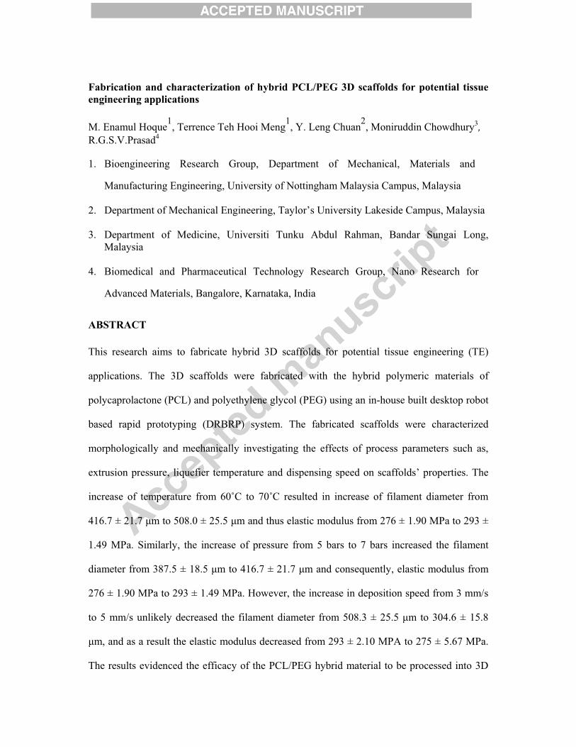
Fabrication and characterization of hybrid PCL/PEG 3D scaffolds for potential tissue engineering applications M. Enamul Hoque1, Terrence Teh Hooi Meng1, Y. Leng Chuan2, Moniruddin Chowdhury3
��
R.G.S.V.Prasad4 1. Bioengineering Research Group, Department of Mechanical, Materials and
Manufacturing Engineering, University of Nottingham Malaysia Campus, Malaysia 2. Department of Mechanical Engineering, Taylor’s University Lakeside Campus, Malaysia
3. Department of Medicine, Universiti Tunku Abdul Rahman, Bandar Sungai Long,
Malaysia
4. Biomedical and Pharmaceutical Technology Research Group, Nano Research for
Advanced Materials, Bangalore, Karnataka, India
ABSTRACT This research aims to fabricate hybrid 3D scaffolds for potential tissue engineering (TE)
applications. The 3D scaffolds were fabricated with the hybrid polymeric materials of
polycaprolactone (PCL) and polyethylene glycol (PEG) using an in-house built desktop robot
based rapid prototyping (DRBRP) system. The fabricated scaffolds were characterized
morphologically and mechanically investigating the effects of process parameters such as,
extrusion pressure, liquefier temperature and dispensing speed on scaffolds’ properties. The
increase of temperature from 60�C to 70�C resulted in increase of filament diameter from
416.7 ± 21.7 �m to 508.0 ± 25.5 �m and thus elastic modulus from 276 ± 1.90 MPa to 293 ±
1.49 MPa. Similarly, the increase of pressure from 5 bars to 7 bars increased the filament
diameter from 387.5 ± 18.5 �m to 416.7 ± 21.7 �m and consequently, elastic modulus from
276 ± 1.90 MPa to 293 ± 1.49 MPa. However, the increase in deposition speed from 3 mm/s
to 5 mm/s unlikely decreased the filament diameter from 508.3 ± 25.5 �m to 304.6 ± 15.8
�m, and as a result the elastic modulus decreased from 293 ± 2.10 MPA to 275 ± 5.67 MPa.
The results evidenced the efficacy of the PCL/PEG hybrid material to be processed into 3D
scaffolds via DRBRP system for potential TE applications.
Keywords: Hybrid, Scaffold, Tissue Engineering, Rapid Prototyping, Polycaprolactone (PCL), Polyethylene glycol (PEG)
1
1. Introduction
The novel concept of hybrid scaffold involves integration of two or more materials with
different compositional entities into a single scaffold unit. The hybrid scaffold is presumed to
enhance biomechanical properties through modulation of the compositional variation that widens
the potential applications of this scaffold to cater for various tissue engineering needs.In this
research, polycaprolactone (PCL) and polyethylene glycol (PEG) were hybridized and processed
into 3D porous TE scaffolds via an in-house built desktop robot based rapid prototyping
(DRBRP) system. Both the PCL and PEG polymers were FDA-approved for clinical applications
[1, 2].Besides, the RP techniques have strong control over the scaffold’s pore shape, size,
distribution and interconnectivity, which can mimic the natural extra cellular matrix of the
organ/tissue to be replaced/regenerated [3-5]. Hydrophobicity and lack of functional groups are
major shortcomings of PCL scaffolds, which result in limited cell attachment and proliferation
[6]. To enhance cell-compatibility of PCL scaffolds we blended PCL with PEG to fabricate
hybrid 3D TE scaffolds using DRBRP system.
2. Materials and methods
PCL (Mn 45,000) and PEG (Mn 10000) were purchased from Sigma Aldrich. Hybrid
material was obtained by combining both PCL and PEG with different compositional ratios. In
this study, the composition used was 70-30 of PCL/PEG on weight percentage basis. The
DRBRP system was utilized to develop the 3D scaffolds layer-by-layer. Overall component of
the system consisted of a computer-guided desktop robot (Sony ROBO Kids), Nitrogen (N2) gas
supply, which was regulated by an air pressure regulator, an electric powered thermocouple
heater and a pneumatic dispenser. The molten polymer was dispensed and deposited as filament
layers on top of each other at a specified filament orientation, called lay-down pattern. The
process completed as the desired thickness of the scaffold was achieved.
2
The hybrid combination was used to investigate the feasibility of scaffold fabrication using
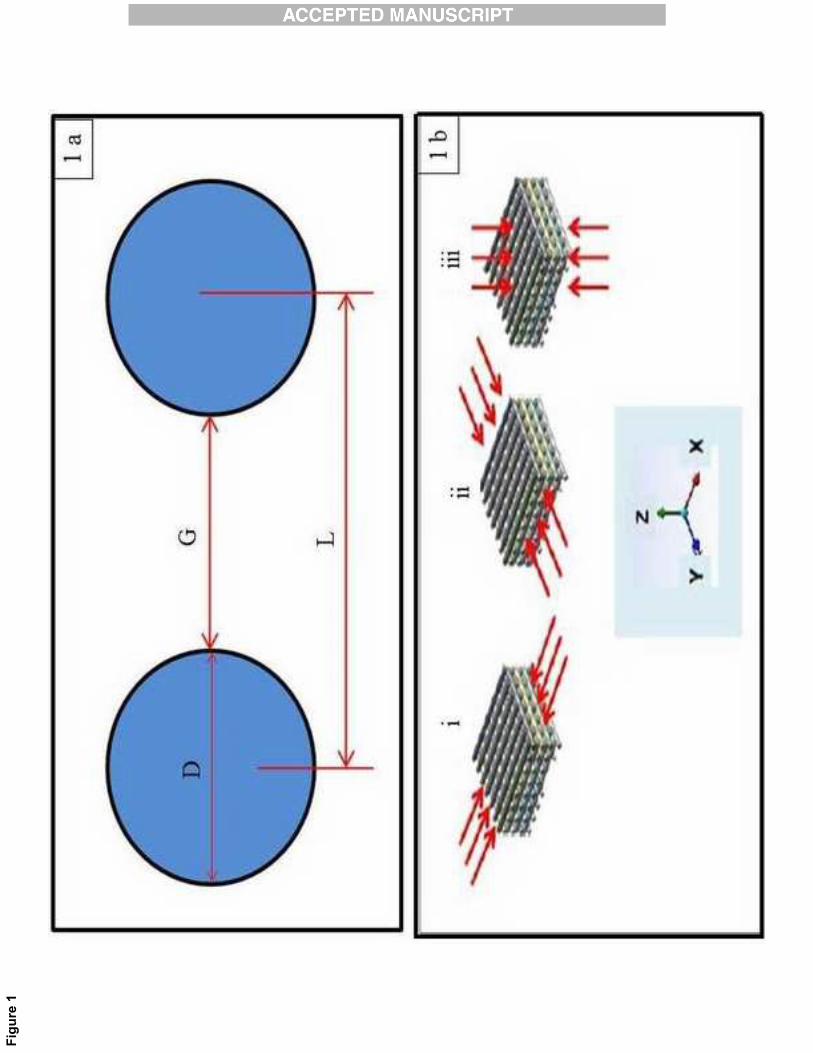
this DRBRP system. The lay-down pattern, nozzle size and filament distance were set as 0-90°,
0.4mm and 1.5mm, respectively. The definitions of filament distance (L), filament diameter (D),
and filament gap were demonstrated in Fig.1a.The scaffolds were built with dimensions of
35x35x5.0mm3 on a flat plastic platform. The fabricated scaffolds were then cut into the
dimensions of 5.0x5.0x5.0 mm3 for further characterization. Influences of processes parameters
were studied by fabricating the scaffolds with a single lay-down pattern of 0-90°, and applying
three values of each process parameter. One parameter was varied while other two parameters
remained unchanged. The process parameters were varied as liquefier temperatures of 60, 65 &
70oC, extrusion pressures of 5, 6 & 7bars, and dispensing speed of 3, 4 & 5mm/s. The
morphology of the fabricated scaffolds was observed under a scanning electron microscope
(SEM) (FEI Quanta 400F) operating at a voltage of 10 kV. Thermal behavior and crystallinity of
the materials were determined using DSC (Heat flux Pyris 6 DSC, Perkin-Elmer). Crystallinity
fractions were calculated relative to enthalpy value of 139.5 Jg�1 for 100% crystalline PCL [7].
Mechanical characterization of the scaffolds with dimensions of 6.0 x 6.0 x 5.0 mm3 (sample
size, n=6) was performed through uniaxial compression test using a uniaxial testing machine
(INSTRON 3342Q8799) with 500 N load-cell. Here, the standard ASTM F451-99a was used as
a reference guide to determine the mechanical properties of scaffolds with similar geometry [8,
9]. All the samples were compressed along the Z-direction (Fig. 1b), and the rate of compression
was 1.5mm/min.
3. Results and discussions Thermal properties of both raw materials and processed scaffold material were obtained from DSC analyses (as shown in Table 1). The degree of crystallinity was calculated using the
equation below:� 0
� 100%mc
m
HXH
� �� �� ��
�
3
� The thermal analysis results are presented in Table 1. The polymer samples melted in the
temperature range of 60°C to 63°C. The melting enthalpy and crystallinity fraction values of the
raw and processed polymers ranged from 63.47 J/g to 65.57J/g and 45% to 47%, respectively.
The shear forces of the filament extrusion process did not cause any significant alteration of
thermal properties when the polymers were extruded into scaffolds. The consistency in thermal
analysis data indicates the favorable rheological properties and thermal stability of the polymers
(PCL and hybrid PCL/PEG) to be processed into 3D scaffolds utilizing DRBRP system.
The key process parameters of the DRBRP system are (i) liquefier temperature - supplied by a
thermocouple heater, (ii) extrusion pressure - regulated by a pneumatic system, and (iii)
deposition speed – controlled by the robotic movement. The effects of these parameters were
investigated with the aim of optimizing the parameters for producing scaffolds with properties as
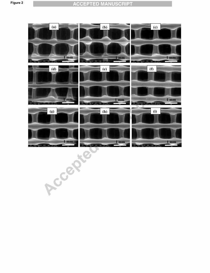
required. The scaffolds’ morphological changes due to variation of the process parameters are
demonstrated in Fig. 2. The increase of temperature from 60�C to 70�C resulted in increase of
filament diameter from 416.7 ± 21.7 �m to 508.0 ± 25.5 �m, which accordingly decreased the
filament gap from 846.9 ± 28.6 �m to 806.3 ± 24.3 �m (Figs. 2a, b & c). The higher liquefier
temperature decreased the polymer viscosity and in turn, the higher fluidity caused excessive
dispensing of the polymer at the nozzle tip and further spreading on the platform leading to
formation of thicker filament. However, too high temperature might result in irregularity and
distortion in the scaffold structure. In contrary, too low liquefier temperature might pose
difficulties in extruding the polymer melts or even preventing dispensing process due to the fast
solidification of the molten polymer at the nozzle tip. Similar to liquefier temperature, the
increase of pressure from 5 bars to 7 bars increased the filament diameter from 387.5 ± 18.5 �m
to 416.7 ± 21.7 �m and consequently, decreased the filament gap from 1119 ± 37.4 �m to 846.9
± 28.6 �m (Figs. 2d, e & f). A higher extrusion pressure led to higher polymer flow per travel
distance that resulted in the formation of larger filament diameter.
4
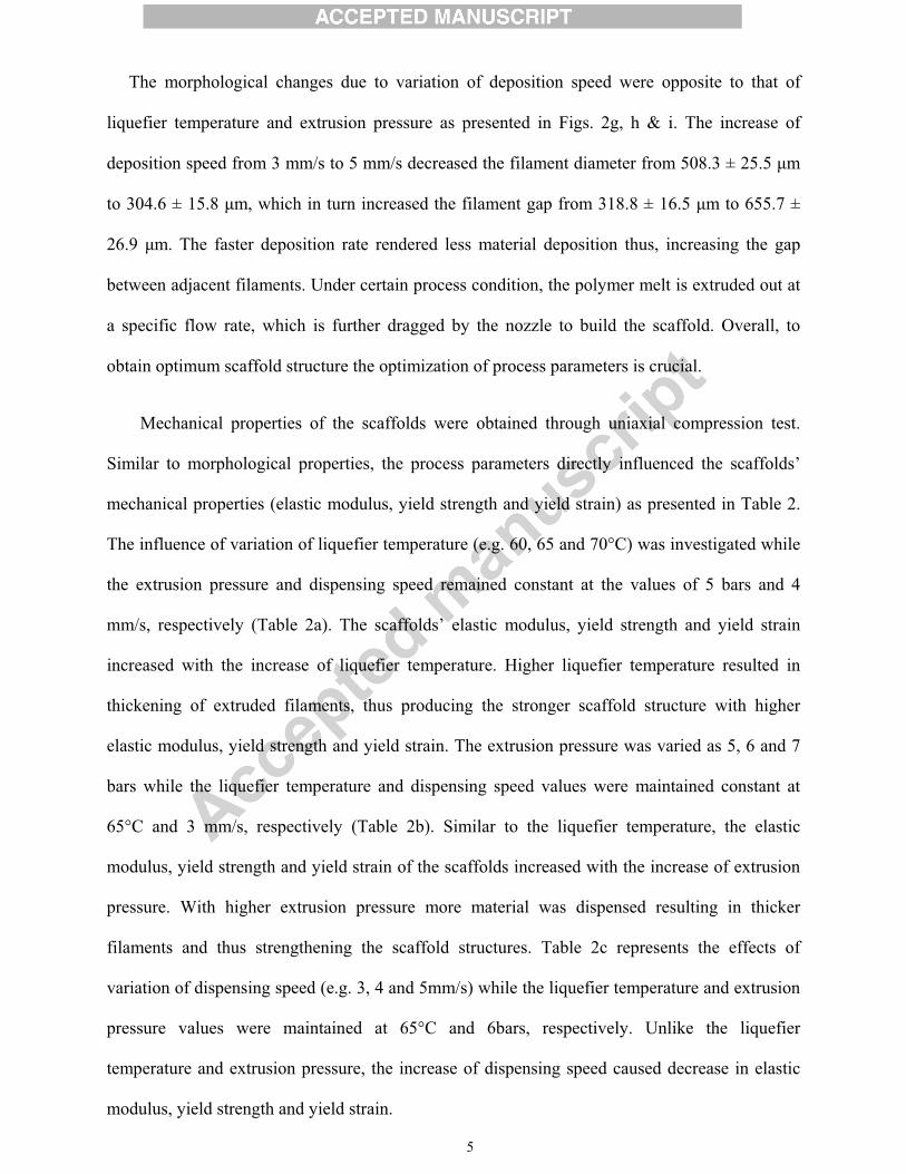
The morphological changes due to variation of deposition speed were opposite to that of
liquefier temperature and extrusion pressure as presented in Figs. 2g, h & i. The increase of
deposition speed from 3 mm/s to 5 mm/s decreased the filament diameter from 508.3 ± 25.5 �m
to 304.6 ± 15.8 �m, which in turn increased the filament gap from 318.8 ± 16.5 �m to 655.7 ±
26.9 �m. The faster deposition rate rendered less material deposition thus, increasing the gap
between adjacent filaments. Under certain process condition, the polymer melt is extruded out at
a specific flow rate, which is further dragged by the nozzle to build the scaffold. Overall, to
obtain optimum scaffold structure the optimization of process parameters is crucial.
Mechanical properties of the scaffolds were obtained through uniaxial compression test.
Similar to morphological properties, the process parameters directly influenced the scaffolds’
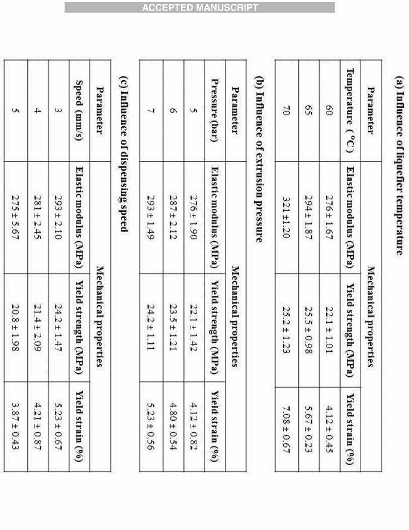
mechanical properties (elastic modulus, yield strength and yield strain) as presented in Table 2.
The influence of variation of liquefier temperature (e.g. 60, 65 and 70°C) was investigated while
the extrusion pressure and dispensing speed remained constant at the values of 5 bars and 4
mm/s, respectively (Table 2a). The scaffolds’ elastic modulus, yield strength and yield strain
increased with the increase of liquefier temperature. Higher liquefier temperature resulted in
thickening of extruded filaments, thus producing the stronger scaffold structure with higher
elastic modulus, yield strength and yield strain. The extrusion pressure was varied as 5, 6 and 7
bars while the liquefier temperature and dispensing speed values were maintained constant at
65°C and 3 mm/s, respectively (Table 2b). Similar to the liquefier temperature, the elastic
modulus, yield strength and yield strain of the scaffolds increased with the increase of extrusion
pressure. With higher extrusion pressure more material was dispensed resulting in thicker
filaments and thus strengthening the scaffold structures. Table 2c represents the effects of
variation of dispensing speed (e.g. 3, 4 and 5mm/s) while the liquefier temperature and extrusion
pressure values were maintained at 65°C and 6bars, respectively. Unlike the liquefier
temperature and extrusion pressure, the increase of dispensing speed caused decrease in elastic
modulus, yield strength and yield strain.
5
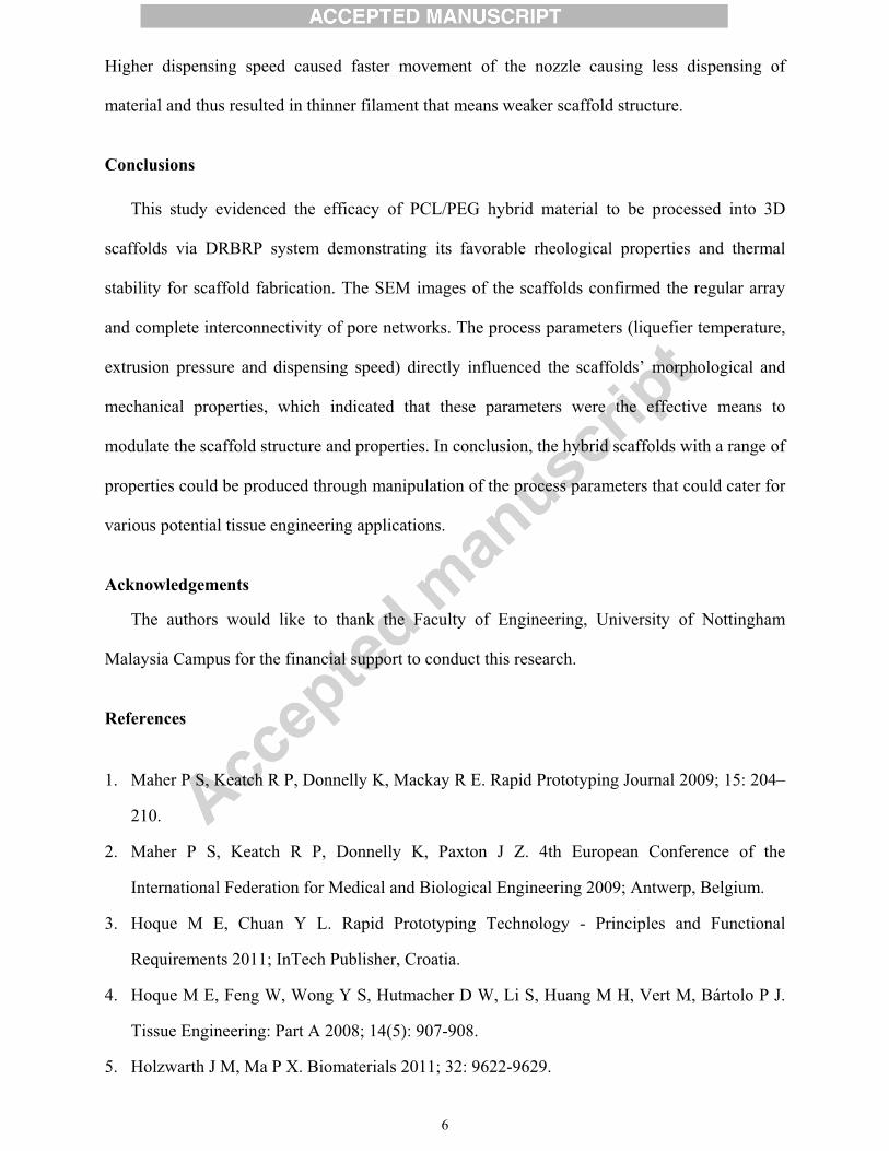
Higher dispensing speed caused faster movement of the nozzle causing less dispensing of
material and thus resulted in thinner filament that means weaker scaffold structure.
Conclusions
This study evidenced the efficacy of PCL/PEG hybrid material to be processed into 3D
scaffolds via DRBRP system demonstrating its favorable rheological properties and thermal
stability for scaffold fabrication. The SEM images of the scaffolds confirmed the regular array
and complete interconnectivity of pore networks. The process parameters (liquefier temperature,
extrusion pressure and dispensing speed) directly influenced the scaffolds’ morphological and
mechanical properties, which indicated that these parameters were the effective means to
modulate the scaffold structure and properties. In conclusion, the hybrid scaffolds with a range of
properties could be produced through manipulation of the process parameters that could cater for
various potential tissue engineering applications.
Acknowledgements
The authors would like to thank the Faculty of Engineering, University of Nottingham
Malaysia Campus for the financial support to conduct this research.
References 1. Maher P S, Keatch R P, Donnelly K, Mackay R E. Rapid Prototyping Journal 2009; 15: 204–
210.
2. Maher P S, Keatch R P, Donnelly K, Paxton J Z. 4th European Conference of the
International Federation for Medical and Biological Engineering 2009; Antwerp, Belgium.
3. Hoque M E, Chuan Y L. Rapid Prototyping Technology - Principles and Functional
Requirements 2011; InTech Publisher, Croatia.
4. Hoque M E, Feng W, Wong Y S, Hutmacher D W, Li S, Huang M H, Vert M, Bártolo P J.
Tissue Engineering: Part A 2008; 14(5): 907-908.
5. Holzwarth J M, Ma P X. Biomaterials 2011; 32: 9622-9629.
6
6. Woodruff MA, Hutmacher DW. Progress in Polymer Science 2010; 35:1217–56.
7. Pitt C G, Zhong-Wei G. Journal of Controlled Release 1987; 4: 283-292.
8. Zein I, Hutmacher D W, Schantz J T, Al E. International Workshop on Advances in
Materials Science and Technology 2000; Singapore.
9. Thomson R C, Shung A K, Yaszemski M J, Mikos A G. Polymer Scaffold Processing. In:
Lanza R, Langer R, Vacant J P. (eds.) Principles of Tissue Engineering. Second Edition
ed. 2000; Academic Press, California.
Figure Captions Figure 1: (a) Model of a 0-90 single-angle scaffold design. D: Filament diameter, L: Filament distance, G: Filament gap; (b) 3D scaffold models showing various loading planes e.g. (i) X-plane, (ii) Y-plane and (iii) Z-plane.
Figure 2: SEM images of PCL/PEG hybrid scaffolds fabricated with nozzle size of 0.4mm,laydown pattern of 0-90, and filament distance of 1.5mm showing the effects of process
parameters on the scaffold structure. Liquefier temperatures were varied as (a) 60oC, (b)
65oC and (c) 70oC while extrusion pressure and dispensing speed remained unchanged at 6
bars and 4 mm/s, respectively; Extrusion pressures were varied as (d) 5 bars, (e) 6 bars and
(f) 7 bars while liquefier temperature and dispensing speed remained unchanged at 65oC and
4 mm/s, respectively; And dispensing speeds were varied as (g) 3 mm/s, (h) 4 mm/s and (i) 5
mm/s while liquefier temperature and extrusion pressure remained unchanged at 65oC and 6
bars, respectively;
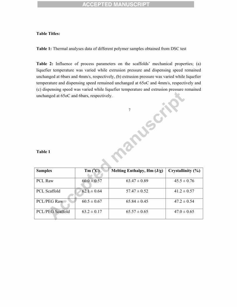
Table Titles: Table 1: Thermal analyses data of different polymer samples obtained from DSC test Table 2: Influence of process parameters on the scaffolds’ mechanical properties; (a) liquefier temperature was varied while extrusion pressure and dispensing speed remained unchanged at 6bars and 4mm/s, respectively, (b) extrusion pressure was varied while liquefier temperature and dispensing speed remained unchanged at 65oC and 4mm/s, respectively and (c) dispensing speed was varied while liquefier temperature and extrusion pressure remained unchanged at 65oC and 6bars, respectively.
7 �
�
�
�
Table 1�
�
Samples Tm (oC) Melting Enthalpy, Hm (J/g) Crystallinity (%)
PCL Raw 60.0 ± 0.57 63.47 ± 0.89 45.5 ± 0.76
PCL Scaffold 62.1 ± 0.64 57.47 ± 0.52 41.2 ± 0.57
PCL/PEG Raw 60.5 ± 0.67 65.84 ± 0.45 47.2 ± 0.54
PCL/PEG Scaffold 63.2 ± 0.17 65.57 ± 0.65 47.0 ± 0.65
�
� �

Highlights
This study investigates the feasibility of processing PCL/PEG hybrid material into 3D scaffolds using an in-house built desktop robot based rapid prototyping system.
The integrated scaffold structure with fully interconnected pore network evidenced the suitability of the PCL/PEG hybrid material for scaffold fabrication.
It was observed that the process parameters (liquefier temperature, extrusion pressure and deposition speed) had direct influence on the scaffolds’ morphological and consequently, mechanical properties.
The variation of scaffolds’ properties due to change of process parameters demonstrates the feasibility of modulating the scaffold structures and characteristics to cater for various tissue engineering applications as required.
�
Figu
re 1
(a)
1 mm
(c)
1 mm
(f)
1 mm
(e)
1 mm
(d)
1 mm
(g)
1 mm
(h)
1 mm
(i)
1 mm
(b)
1 mm
Figure 2