Efficient method dispatch in PCL
124
Maintenance & Service Guide HP Compaq 6000 Pro All-in-One PC
-
Upload
mas-anime-site50 -
Category
Documents
-
view
4 -
download
0
Transcript of Efficient method dispatch in PCL

Maintenance & Service Guide
HP Compaq 6000 Pro All-in-One PC

© Copyright 2010, 2011 Hewlett-PackardDevelopment Company, L.P. The informationcontained herein is subject to changewithout notice.
Microsoft and Windows are trademarks ofMicrosoft Corporation in the U.S. and othercountries.
The only warranties for HP products andservices are set forth in the express warrantystatements accompanying such products andservices. Nothing herein should beconstrued as constituting an additionalwarranty. HP shall not be liable for technicalor editorial errors or omissions containedherein.
This document contains proprietaryinformation that is protected by copyright.No part of this document may bephotocopied, reproduced, or translated toanother language without the prior writtenconsent of Hewlett-Packard Company.
Maintenance & Service Guide
HP Compaq 6000 Pro All-in-One PC
Second Edition (May 2011)
First Edition (June 2010)
Document Part Number: 628499-002

About This Book
WARNING! Text set off in this manner indicates that failure to follow directions could result in bodilyharm or loss of life.
CAUTION: Text set off in this manner indicates that failure to follow directions could result in damageto equipment or loss of information.
NOTE: Text set off in this manner provides important supplemental information.
iii

iv About This Book

Table of contents
1 Product Features ............................................................................................................... 1
Front Components .................................................................................................................... 3Rear and Side Components ....................................................................................................... 4
2 Installing and Customizing the Software ........................................................................... 5
Installing the Operating System .................................................................................................. 5Downloading Microsoft Windows Updates ................................................................................. 6Installing or Upgrading Device Drivers (Windows systems) ............................................................ 6Accessing Disk Image (ISO) Files ............................................................................................... 6Protecting the Software ............................................................................................................. 7
3 Computer Setup (F10) Utility ............................................................................................. 8
Computer Setup (F10) Utilities ................................................................................................... 8Using Computer Setup (F10) Utilities ............................................................................ 9Computer Setup—File .............................................................................................. 11Computer Setup—Storage ........................................................................................ 12Computer Setup—Security ........................................................................................ 14Computer Setup—Power .......................................................................................... 18Computer Setup—Advanced .................................................................................... 19
Recovering the Configuration Settings ....................................................................................... 22
4 Serial ATA (SATA) Drive Guidelines and Features ............................................................ 23
SATA Hard Drives .................................................................................................................. 23SATA Hard Drive Cables ........................................................................................................ 23
SATA Data Cable ................................................................................................... 23SMART ATA Drives ................................................................................................................. 24Hard Drive Capacities ............................................................................................................ 24
5 Identifying the Chassis, Routine Care, and Disassembly Preparation ............................... 25
Chassis Designation ............................................................................................................... 25All-in One .............................................................................................................. 25
v

Electrostatic Discharge Information ........................................................................................... 26Generating Static .................................................................................................... 26Preventing Electrostatic Damage to Equipment ............................................................ 26Personal Grounding Methods and Equipment ............................................................. 27Grounding the Work Area ....................................................................................... 27Recommended Materials and Equipment .................................................................... 28
Operating Guidelines ............................................................................................................. 28Routine Care ......................................................................................................................... 29
General Cleaning Safety Precautions ......................................................................... 29Cleaning the Computer Case .................................................................................... 29Cleaning the Keyboard ............................................................................................ 29Cleaning the Monitor ............................................................................................... 30Cleaning the Mouse ................................................................................................ 30
Service Considerations ........................................................................................................... 30Tools and Software Requirements .............................................................................. 31Screws ................................................................................................................... 31Cables and Connectors ............................................................................................ 31Hard Drives ............................................................................................................ 31Lithium Coin Cell Battery .......................................................................................... 32
6 Illustrated parts catalog .................................................................................................. 33
Computer major components ................................................................................................... 33Mass storage devices ............................................................................................................. 37Cables .................................................................................................................................. 38Sequential part number listing .................................................................................................. 38
7 Removal and Replacement Procedures All-in One (AIO) Chassis ...................................... 42
Preparing to Disassemble the Computer .................................................................................... 42Small Rear Cover ................................................................................................................... 43Port Cover ............................................................................................................................. 44Stand ................................................................................................................................... 45Optical Drive ......................................................................................................................... 46Hard Drive ............................................................................................................................ 49Memory ................................................................................................................................ 52Upper Rear Panel ................................................................................................................... 54Webcam Module ................................................................................................................... 56Bluetooth Module ................................................................................................................... 58Small Fan .............................................................................................................................. 60Heat Sink (Thermal Module) .................................................................................................... 61Processor .............................................................................................................................. 62Graphics Board ..................................................................................................................... 64
vi

Rear I/O Cover ..................................................................................................................... 66TV Tuner Module .................................................................................................................... 68Cable Connector .................................................................................................................... 70WLAN Module ...................................................................................................................... 72Outer/Left Rear Panel ............................................................................................................. 74Display Control Board ............................................................................................................ 76Power Button Board ................................................................................................................ 78Inverter Board ........................................................................................................................ 80Optical Drive Connector Board ................................................................................................ 82Hood Sensor ......................................................................................................................... 84Hard Drive Connector ............................................................................................................. 86Fan ...................................................................................................................................... 88Speakers ............................................................................................................................... 90System Board Shield ............................................................................................................... 91System Board ........................................................................................................................ 93Display Panel ........................................................................................................................ 95
Appendix A POST Error Messages ...................................................................................... 97
POST Numeric Codes and Text Messages ................................................................................. 98Interpreting POST Diagnostic Front Panel LEDs and Audible Codes ............................................. 105
Appendix B Connector Pin Assignments ........................................................................... 109
Ethernet BNC ...................................................................................................................... 109USB .................................................................................................................................... 109Microphone ........................................................................................................................ 109Headphone ......................................................................................................................... 110Line-in Audio ....................................................................................................................... 110Line-out Audio ...................................................................................................................... 110
Appendix C Power Cord Set Requirements ....................................................................... 111
General Requirements .......................................................................................................... 111Japanese Power Cord Requirements ....................................................................................... 111Country-Specific Requirements ............................................................................................... 112
Appendix D Specifications ............................................................................................... 113
All-in One Models ................................................................................................................ 113
Index ............................................................................................................................... 114
vii

viii

1 Product Features
The HP Compaq 6000 Pro All-In One Business PC offers the following features:
● Intel® Core™ 2 Duo processors
● Windows® 7 Professional 32- or 64-bit operating system
● Up to 8 gigabytes (GB) of DDR3 memory
● Hard drives up to 1 terabyte
● Optional 80-GB solid-state drive
● 21.5-inch diagonal widescreen Full HD WLED anti-glare display (1080p)
● Bluetooth® wireless solutions
● 16x Max SuperMulti optical drive and slim-tray DVD burner with Lightscribe
● 7 USB ports
● IEEE 1394 Firewire® port
● 6-in-1 memory card reader
● Integrated Intel Graphics Media Accelerator 4500 HD, or optional NVIDIA GeForce GT230discrete graphics
● Optional TV tuner
● PS/2 ports for the mouse and keyboard
● Removable panels on the back of the chassis allow administrators to easily and efficiently servicethe PC
● Adjustable tilt and swivel stand
● Intel Q43 Express chipset
● Optional wireless connectivity:
◦ 802.11 b/g/n wireless LAN module
◦ Bluetooth® 2.1
● Intel Standard Manageability
1

● Face Recognition for HP ProtectTools software with auto-login capabilities
● TPM 1.2-compliant embedded security chip
● VESA-compliant mounting solutions
● HD webcam
● Dual-array microphone
● Premium stereo speakers
● HP SkyRoom full version for professional quality visual collaboration built on HP Video and Imageprocessing engines for hi-fi audio, hi-def video, and hi-performance 3D application sharing
NOTE: SkyRoom is shipped only on computers with Dual Core Processors, at least 2 GB ofmemory, a selectable Windows operating system, and the selectable webcam/mic AV.
● Microsoft® Office Communicator certified
● ENERGY STAR® qualified, EPEAT® Gold registered, and offers 89-percent energy-efficient power
● HP Power Assistant software
● HP MediaSmart software for photos, music, video, DVD, webcam, and TV tuner
● Choice of wired or wireless keyboard and mouse
2 Chapter 1 Product Features

Front Components
Component Component
(1) Dual microphone array (8) Drive activity LED
(2) Webcam (optional) (9) Power button and LED
(3) 21.5-inch diagonal 16:9 widescreen LED-backlit full HD LCD display
(10) High-performance stereo speakers
(4) Tray-load optical drive (optional) (11) IR Receiver and LED (select models only)
(5) Optical drive eject button (12) Adjustable tilt and swivel stand
(6) Brightness increase button (13) HP low-profile keyboard* with numeric keypad
(7) Brightness decrease button (14) HP optical mouse*
*Wired or optional wireless
Front Components 3
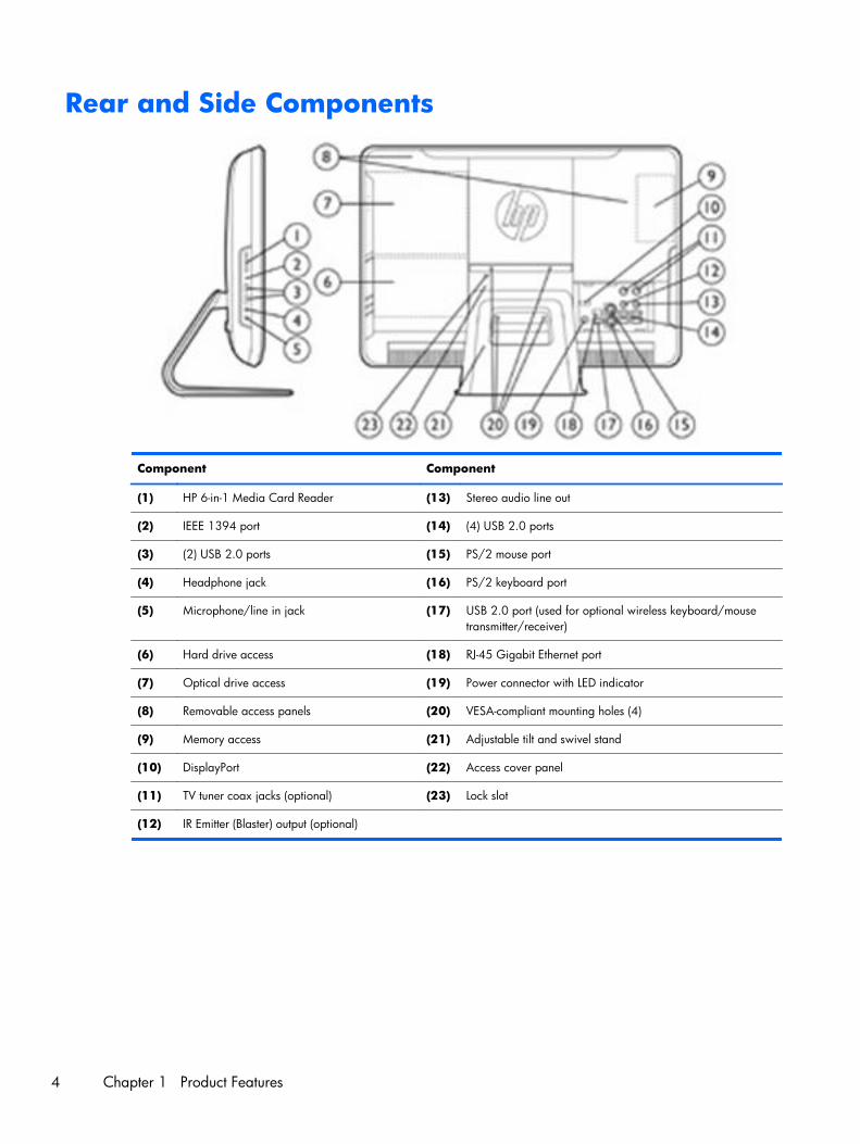
Rear and Side Components
Component Component
(1) HP 6-in-1 Media Card Reader (13) Stereo audio line out
(2) IEEE 1394 port (14) (4) USB 2.0 ports
(3) (2) USB 2.0 ports (15) PS/2 mouse port
(4) Headphone jack (16) PS/2 keyboard port
(5) Microphone/line in jack (17) USB 2.0 port (used for optional wireless keyboard/mousetransmitter/receiver)
(6) Hard drive access (18) RJ-45 Gigabit Ethernet port
(7) Optical drive access (19) Power connector with LED indicator
(8) Removable access panels (20) VESA-compliant mounting holes (4)
(9) Memory access (21) Adjustable tilt and swivel stand
(10) DisplayPort (22) Access cover panel
(11) TV tuner coax jacks (optional) (23) Lock slot
(12) IR Emitter (Blaster) output (optional)
4 Chapter 1 Product Features

2 Installing and Customizing theSoftware
If your computer was not shipped with a Microsoft operating system, some portions of thisdocumentation do not apply. Additional information is available in online help after you install theoperating system.
NOTE: If the computer was shipped with Windows Vista or Windows 7 loaded, you will beprompted to register the computer with HP Total Care before installing the operating system. You willsee a brief movie followed by an online registration form. Fill out the form, click the Begin button, andfollow the instructions on the screen.
CAUTION: Do not add optional hardware or third-party devices to the computer until the operatingsystem is successfully installed. Doing so may cause errors and prevent the operating system frominstalling properly.
NOTE: Be sure there is a 10.2-cm (4-inch) clearance at the back of the unit and above the monitor topermit the required airflow.
Installing the Operating SystemThe first time you turn on the computer, the operating system is installed automatically. This processtakes about 5 to 10 minutes, depending on which operating system is being installed. Carefully readand follow the instructions on the screen to complete the installation.
CAUTION: Once the automatic installation has begun, DO NOT TURN OFF THE COMPUTER UNTILTHE PROCESS IS COMPLETE. Turning off the computer during the installation process may damage thesoftware that runs the computer or prevent its proper installation.
NOTE: If the computer shipped with more than one operating system language on the hard drive, theinstallation process could take up to 60 minutes.
If your computer was not shipped with a Microsoft operating system, some portions of thisdocumentation do not apply. Additional information is available in online help after you install theoperating system.
Installing the Operating System 5

Downloading Microsoft Windows Updates1. To set up your Internet connection, click Start > Internet Explorer and follow the instructions
on the screen.
2. Once an Internet connection has been established, click the Start button.
3. Select the All Programs menu.
4. Click on the Windows Update link.
In Windows Vista and Windows 7, the Windows Update screen appears. Click viewavailable updates and make sure all critical updates are selected. Click the Install button andfollow the instructions on the screen.
In Windows XP, you will be directed to the Microsoft Windows Update Web site. If you seeone or more pop-up windows that ask you to install a program from http://www.microsoft.com,click Yes to install the program. Follow the instructions on the Microsoft Web site to scan forupdates and install critical updates and service packs.
It is recommended that you install all of the critical updates and service packs.
5. After the updates have been installed, Windows will prompt you to reboot the machine. Be sure tosave any files or documents that you may have open before rebooting. Then select Yes to rebootthe machine.
Installing or Upgrading Device Drivers (Windowssystems)
When installing optional hardware devices after the operating system installation is complete, you mustalso install the drivers for each of the devices.
If prompted for the i386 directory, replace the path specification with C:\i386, or use the Browsebutton in the dialog box to locate the i386 folder. This action points the operating system to theappropriate drivers.
Obtain the latest support software, including support software for the operating system fromhttp://www.hp.com/support. Select your country and language, select Download drivers andsoftware (and firmware), enter the model number of the computer, and press Enter.
Accessing Disk Image (ISO) FilesThere are disk image files (ISO files) included on your PC that contain the installation software foradditional software. These CD image files are located in the folder C:\SWSetup\ISOs. Each .iso filecan be burned to CD media to create an installation CD. It is recommended that these disks be created
6 Chapter 2 Installing and Customizing the Software

and the software installed in order to get the most from your PC. The software and image file namesare:
● Corel WinDVD SD and BD – installation software for WinDVD – used to play DVD movies
● HP Insight Diagnostics OR Vision Diagnostics – software to perform diagnostic activities on yourPC
Protecting the SoftwareTo protect the software from loss or damage, keep a backup copy of all system software, applications,and related files stored on the hard drive. Refer to the operating system or backup utility documentationfor instructions on making backup copies of your data files.
Protecting the Software 7

3 Computer Setup (F10) Utility
Computer Setup (F10) UtilitiesUse Computer Setup (F10) Utility to do the following:
● Change factory default settings.
● Set the system date and time.
● Set, view, change, or verify the system configuration, including settings for processor, graphics,memory, audio, storage, communications, and input devices.
● Modify the boot order of bootable devices such as hard drives, optical drives, or USB flash mediadevices.
● Enable Quick Boot, which is faster than Full Boot but does not run all of the diagnostic tests runduring a Full Boot. You can set the system to:
❑ always Quick Boot (default);
❑ periodically Full Boot (from every 1 to 30 days); or
❑ always Full Boot.
● Select Post Messages Enabled or Disabled to change the display status of Power-On Self-Test(POST) messages. Post Messages Disabled suppresses most POST messages, such as memorycount, product name, and other non-error text messages. If a POST error occurs, the error isdisplayed regardless of the mode selected. To manually switch to Post Messages Enabled duringPOST, press any key (except F1 through F12).
● Establish an Ownership Tag, the text of which is displayed each time the system is turned on orrestarted.
● Enter the Asset Tag or property identification number assigned by the company to this computer.
● Enable the power-on password prompt during system restarts (warm boots) as well as duringpower-on.
● Establish a setup password that controls access to the Computer Setup (F10) Utility and the settingsdescribed in this section.
● Secure integrated I/O functionality, including USB, audio, or embedded NIC, so that they cannotbe used until they are unsecured.
8 Chapter 3 Computer Setup (F10) Utility

● Enable or disable removable media boot ability.
● Solve system configuration errors detected but not automatically fixed during the Power-On Self-Test (POST).
● Replicate the system setup by saving system configuration information on a USB flash drive andrestoring it on one or more computers.
● Execute self-tests on a specified ATA hard drive (when supported by drive).
● Enable or disable DriveLock security (when supported by drive).
Using Computer Setup (F10) Utilities
Computer Setup can be accessed only by turning the computer on or restarting the system. To accessthe Computer Setup Utilities menu, complete the following steps:
1. Turn on or restart the computer. If you are in Microsoft Windows, click Start > Shut Down >Restart.
2. As soon as the computer is turned on, press F10 before the computer boots to the operatingsystem to enter Computer Setup. Press Enter to bypass the title screen, if necessary.
NOTE: If you do not press F10 at the appropriate time, you must restart the computer and againpress F10 before the computer boots to the operating system to access the utility.
3. Select your language from the list and press Enter.
4. A choice of five headings appears in the Computer Setup Utilities menu: File, Storage, Security,Power, and Advanced.
5. Use the arrow (left and right) keys to select the appropriate heading. Use the arrow (up and down)keys to select the option you want, then press Enter. To return to the Computer Setup Utilitiesmenu, press Esc.
6. To apply and save changes, select File > Save Changes and Exit.
● If you have made changes that you do not want applied, select Ignore Changes andExit.
● To reset to factory settings or previously saved default settings (some models), select ApplyDefaults and Exit. This option will restore the original factory system defaults.
CAUTION: Do NOT turn the computer power OFF while the BIOS is saving the Computer Setup(F10) changes because the CMOS could become corrupted. It is safe to turn off the computer only afterexiting the F10 Setup screen.
Table 3-1 Computer Setup (F10) Utility
Heading Table
File Table 3-2 Computer Setup—File on page 11
Storage Table 3-3 Computer Setup—Storage on page 12
Security Table 3-4 Computer Setup—Security on page 14
Computer Setup (F10) Utilities 9

Table 3-1 Computer Setup (F10) Utility (continued)
Power Table 3-5 Computer Setup—Power on page 18
Advanced Table 3-6 Computer Setup—Advanced on page 19
10 Chapter 3 Computer Setup (F10) Utility

Computer Setup—File
NOTE: Support for specific Computer Setup options may vary depending on the hardwareconfiguration.
Table 3-2 Computer Setup—File
Option Description
System Information Lists:
● Product name
● SKU number (some models)
● Processor type/speed/stepping
● Installed memory size/speed, number of channels (single or dual) (if applicable)
● Integrated MAC address for embedded, enabled NIC (if applicable)
● System BIOS (includes family name and version)
● Chassis serial number
● Asset tracking number
● ME firmware version
● Management mode
About Displays copyright notice.
Set Time and Date Allows you to set system time and date.
Flash System ROM Allows you to update the system ROM with a BIOS image file located on a USB flash media deviceor CD-ROM.
Replicated Setup Save to Removable Media
Saves system configuration, including CMOS, to a USB flash media device or a diskette-like device(a storage device set to emulate a diskette drive).
Restore from Removable Media
Restores system configuration from a a USB flash media device or a diskette-like device.
Default Setup Save Current Settings as Default
Saves the current system configuration settings as the default.
Restore Factory Settings as Default
Restores the factory system configuration settings as the default.
Apply Defaults andExit
Applies the currently selected default settings and clears any established passwords.
Ignore Changesand Exit
Exits Computer Setup without applying or saving any changes.
Save Changes andExit
Saves changes to system configuration or default settings and exits Computer Setup.
Computer Setup (F10) Utilities 11

Computer Setup—Storage
NOTE: Support for specific Computer Setup options may vary depending on the hardwareconfiguration.
Table 3-3 Computer Setup—Storage
Option Description
DeviceConfiguration
Lists all installed BIOS-controlled storage devices.
When a device is selected, detailed information and options are displayed. The following optionsmay be presented:
Hard Disk: Size, model, firmware, serial number, connector color, SMART, emulation type.
Emulation type has the following choices:
● None (prevents BIOS data accesses and disables it as a boot device)
● Hard Disk (treated as a hard disk)
Translation Mode (ATA disks only)
Lets you select the translation mode to be used for the device. This enables the BIOS to access diskspartitioned and formatted on other systems and may be necessary for users of older versions ofUNIX (e.g., SCO UNIX version 3.2). Options are Automatic, Bit-Shift, LBA Assisted, User, and Off.
User mode allows you to specify the parameters (logical cylinders, heads, and sectors per track)used by the BIOS to translate disk I/O requests (from the operating system or an application) intoterms the hard drive can accept. Logical cylinders may not exceed 1024. The number of heads maynot exceed 256. The number of sectors per track may not exceed 63. These fields are only visibleand changeable when the drive translation mode is set to User.
CAUTION: Ordinarily, the translation mode selected automatically by the BIOS should not bechanged. If the selected translation mode is not compatible with the translation mode that wasactive when the disk was partitioned and formatted, the data on the disk will be inaccessible.
CD-ROM: Model, firmware, serial number, connector color. No emulation options available.
Default Values (ATA disks only)
SATA Defaults
Translation Mode (ATA disks only)
Lets you select the translation mode to be used for the device. This enables the BIOS to access diskspartitioned and formatted on other systems and may be necessary for users of older versions ofUNIX (e.g., SCO UNIX version 3.2). Options are Automatic, Bit-Shift, LBA Assisted, User, and Off.
User mode allows you to specify the parameters (logical cylinders, heads, and sectors per track)used by the BIOS to translate disk I/O requests (from the operating system or an application) intoterms the hard drive can accept. Logical cylinders may not exceed 1024. The number of heads maynot exceed 256. The number of sectors per track may not exceed 63. These fields are only visibleand changeable when the drive translation mode is set to User.
CAUTION: Ordinarily, the translation mode selected automatically by the BIOS should not bechanged. If the selected translation mode is not compatible with the translation mode that wasactive when the disk was partitioned and formatted, the data on the disk will be inaccessible.
12 Chapter 3 Computer Setup (F10) Utility

Table 3-3 Computer Setup—Storage (continued)
Storage Options Removable Media Boot
Enables/disables ability to boot the system from removable media.
SATA Emulation
Allows you to choose how the SATA controller and devices are accessed by the operating system.There are two supported options: AHCI and IDE.
AHCI (default option) - Allows operating systems with AHCI device drivers loaded to takeadvantage of more advanced features of the SATA controller.
IDE - This is the most backwards-compatible setting of the two options. Operating systems usually donot require additional driver support in IDE mode.
NOTE: The AHCI device driver must be installed prior to attempting to boot from an AHCIvolume. If you attempt to boot from an AHCI volume without the required device driver installed, thesystem will crash (blue screen).
DPS Self-Test Allows you to execute self-tests on ATA hard drives capable of performing the Drive ProtectionSystem (DPS) self-tests.
NOTE: This selection will only appear when at least one drive capable of performing the DPS self-tests is attached to the system.
Boot Order Allows you to:
● Specify the order in which attached devices (such as a USB flash media device, hard drive,optical drive, or network interface card) are checked for a bootable operating system image.Each device on the list may be individually excluded from or included for consideration as abootable operating system source.
● Specify the order of attached hard drives. The first hard drive in the order will have priority inthe boot sequence and will be recognized as drive C (if any devices are attached).
NOTE: MS-DOS drive lettering assignments may not apply after a non-MS-DOS operating systemhas started.
Shortcut to Temporarily Override Boot Order
To boot one time from a device other than the default device specified in Boot Order, restart thecomputer and press F9 before the computer boots to the operating system. After POST is completed,a list of bootable devices is displayed. Use the arrow keys to select the preferred bootable deviceand press Enter. The computer then boots from the selected non-default device for this one time.
Computer Setup (F10) Utilities 13

Computer Setup—Security
NOTE: Support for specific Computer Setup options may vary depending on the hardwareconfiguration.
Table 3-4 Computer Setup—Security
Option Description
Setup Password Allows you to set and enable a setup (administrator) password.
NOTE: If the setup password is set, it is required to change Computer Setup options, flash theROM, and make changes to certain plug and play settings under Windows.
See the Desktop Management Guide for more information.
Power-OnPassword
Allows you to set and enable a power-on password. The power-on password prompt appears aftera power cycle. If the user does not enter the correct power-on password, the unit will not boot.
NOTE: This password does not appear on warm boots , such as Ctrl+Alt+Delete or Restartfrom Windows, unless enabled in Password Options (see below).
See the Desktop Management Guide for more information.
Password Options
(This selection appearsonly if a power-onpassword or setuppassword is set.)
Allows you to enable/disable:
● Lock Legacy Resources (appears if a setup password is set)
● Network Server Mode (appears if a power-on password is set)
● Password Prompt on Warm Boot (Ctrl+Alt+Delete) (appears if a power-on password is set)
● Setup Browse Mode (appears if a setup password is set) allows viewing, but not changing, theF10 Setup options without entering setup password.
● Stringent Password (appears if a setup password is set), which when enabled bypasses theonboard password jumper to disable the power-on password.
● Password prompt on F9, F11, & F12 (allows access to menus without entering setup password)
See the Desktop Management Guide for more information.
Device Security Allows you to set Device Available/Device Hidden for:
● System audio
● Network controllers (some models)
● Embedded security device (some models)
● SATA0
● SATA1
● 1394 and Media Reader
14 Chapter 3 Computer Setup (F10) Utility

Table 3-4 Computer Setup—Security (continued)
USB Security Allows you to enable or disable groups of USB ports or individual USB ports:
● Front USB Ports
◦ USB Port 11
◦ USB Port 12
● Rear USB Ports
◦ USB Port 1
◦ USB Port 3
◦ USB Port 8
◦ USB Port 9
◦ USB Port 10
● Accessory USB Ports
◦ USB Port 2
◦ USB Port 4
◦ USB Port 6
◦ USB Port 7
Slot Security Allows you to disable or enable any PCI Express x16 or x1 slot
Network ServiceBoot
Enables/disables the computer’s ability to boot from an operating system installed on a networkserver. (Feature available on NIC models only; the network controller must be either a PCI Expressexpansion card or embedded on the system board.)
System IDs Allows you to set:
● Asset tag (18-byte identifier), a property identification number assigned by the company to thecomputer.
● Ownership tag (80-byte identifier) displayed during POST.
● Chassis serial number or Universal Unique Identifier (UUID) number. The UUID can only beupdated if the current chassis serial number is invalid. (These ID numbers are normally set inthe factory and are used to uniquely identify the system.)
● Keyboard locale setting (for example, English or German) for System ID entry.
DriveLock Security Allows you to assign or modify a master or user password for hard drives. When this feature isenabled, the user is prompted to provide one of the DriveLock passwords during POST. If neither issuccessfully entered, the hard drive will remain inaccessible until one of the passwords issuccessfully provided during a subsequent cold-boot sequence.
NOTE: This selection will only appear when at least one drive that supports the DriveLock featureis attached to the system. You may need to power cycle the system to manage DriveLock-enableddrives.
See the Desktop Management Guide for more information.
Computer Setup (F10) Utilities 15

Table 3-4 Computer Setup—Security (continued)
System Security(some models: theseoptions are hardwaredependent)
Data Execution Prevention (some models) (enable/disable) - Helps prevent operating system securitybreaches.
PAVP (Models with Blu-ray drives) (disabled/min/max) - PAVP enables the Protected Audio VideoPath in the Chipset. This may allow viewing of some protected high definition content that wouldotherwise be prohibited from playback. Selecting Max will assign 96 Megabytes of system memoryexclusively to PAVP.
Virtualization Technology (some models) (enable/disable) - Controls the virtualization features of theprocessor. Changing this setting requires turning the computer off and then back on.
Virtualization Technology Directed I/O (some models) (enable/disable) - Controls virtualizationDMA remapping features of the chipset. Changing this setting requires turning the computer off andthen back on.
Trusted Execution Technology (some models) (enable/disable) - Controls the underlying processorand chipset features needed to support a virtual appliance. Changing this setting requires turningthe computer off and then back on. To enable this feature you must enable the following features:
● Embedded Security Device Support
● Virtualization Technology
● Virtualization Technology Directed I/O
Embedded Security Device Support (some models) (enable/disable) - Permits activation anddeactivation of the Embedded Security Device. Changing this setting requires turning the computeroff and then back on.
NOTE: To configure the Embedded Security Device, a Setup password must be set.
● Reset to Factory Settings (some models) (Do not reset/Reset) - Resetting to factory defaults willerase all security keys. Changing this setting requires turning the computer off and then backon.
CAUTION: The embedded security device is a critical component of many security schemes.Erasing the security keys will prevent access to data protected by the Embedded SecurityDevice. Choosing Reset to Factory Settings may result in significant data loss.
OS management of Embedded Security Device (some models) (enable/disable) - This option allowsthe user to limit operating system control of the Embedded Security Device. Changing this settingrequires turning the computer off and then back on. This option allows the user to limit OS control ofthe Embedded Security Device.
● Reset of Embedded Security Device through OS (some models) (enable/disable) - This optionallows the user to limit the operating system ability to request a Reset to Factory Settings of theEmbedded Security Device. Changing this setting requires turning the computer off and thenback on.
NOTE: To enable this option, a Setup password must be set.
Button Retask Password Protection (disable/enable) - Controls whether or not the Setup passwordmust be provided to WMI methods used to re-task the function of the side panel buttons.
Power Button (enable/disable) - Allows you to disable or enable the power button.
Consumer IR Power Button (enable/disable) - Controls whether or not the BIOS will respond toRemote Control power button presses. This does not affect the Remote Control power buttonoperation in Windows.
Optical Drive Eject Button (enable/disable) - Allows you to disable or enable the optical drive ejectbutton. Disabling the eject button does not disable software control of the eject function insideWindows.
16 Chapter 3 Computer Setup (F10) Utility

Table 3-4 Computer Setup—Security (continued)
Master Boot RecordSecurity
(Enable/Disable) Protects the master boot record from viruses or other corruption. Saves a copy ofthe current master boot record and allows you to restore the saved copy.
Setup Security Level Provides a method to allow end-users limited access to change specified setup options, withouthaving to know the Setup Password.
This feature allows the administrator the flexibility to protect changes to essential setup options,while allowing the user to view system settings and configure nonessential options. Theadministrator specifies access rights to individual setup options on a case-by-case basis via theSetup Security Level menu. By default, all setup options are assigned Setup Password, indicating theuser must enter the correct Setup Password during POST to make changes to any of the options. Theadministrator may set individual items to None, indicating the user can make changes to thespecified options when setup has been accessed with invalid passwords. The choice, None, isreplaced by Power-On Password if a Power-On Password is enabled.
NOTE: Setup Browse Mode must be set to Enable in order for the user to enter Setup withoutknowing the setup password.
Computer Setup (F10) Utilities 17

Computer Setup—Power
NOTE: Support for specific Computer Setup options may vary depending on the hardwareconfiguration.
Table 3-5 Computer Setup—Power
Option Description
OS PowerManagement
● Runtime Power Management— Enable/Disable. Allows certain operating systems to reduceprocessor voltage and frequency when the current software load does not require the fullcapabilities of the processor.
● Idle Power Savings—Extended/Normal. Allows certain operating systems to decrease theprocessors power consumption when the processor is idle.
● ACPI S3 Hard Disk Reset—Enabling this causes the BIOS to ensure hard disks are ready toaccept commands after resuming from S3 before returning control to the operating system.
● ACPI S3 PS2 Mouse Wakeup—Enables or disables waking from S3 due to any PS2 mouseactivity or a button click only.
● USB Wake on Device Insertion (some models)—Allows system to wake from Standby on USBdevice insertion.
● Unique Sleep State Blink Rates—Enable/Disable. This feature is designed to provide a visualindication of what sleep state the system is in. Each sleep state has a unique blink pattern.
◦ S0 = Solid green LED.
◦ S3 = 3 blinks at 1Hz (50% duty cycle) followed by a pause of 2 seconds (green LED) —repeated cycles of 3 blinks and a pause.
◦ S4 = 4 blinks at 1Hz (50% duty cycle) followed by a pause of 2 seconds (green LED) —repeated cycles of 4 blinks and a pause.
◦ S5 = LED is off.
NOTE: If this feature is disabled, S4 and S5 both have the LED off. S3 uses 1 blink persecond.
Hardware PowerManagement
SATA Power Management—Enables or disables the SATA bus and/or device power management.
S5 Maximum Power Savings—Turns off power to all nonessential hardware when system is off tomeet EUP Lot 6 requirement of less than 1 Watt power usage. Enabling this feature will disable anywake events and management devices while in S5.
Thermal Fan idle mode—This bar graph controls the minimum permitted fan speed.
NOTE: This setting only changes the minimum fan speed. The fans are still automaticallycontrolled.
18 Chapter 3 Computer Setup (F10) Utility

Computer Setup—Advanced
NOTE: Support for specific Computer Setup options may vary depending on the hardwareconfiguration.
Table 3-6 Computer Setup—Advanced
Option Heading
Power-On Options Allows you to set:
● POST mode (QuickBoot, Clear Memory, FullBoot, or FullBoot Every x Days).
◦ QuickBoot = Do not clear memory or perform a memory test.
◦ FullBoot = Memory test (count) on cold boot. Clears memory on all boots.
Computer Setup (F10) Utilities 19

Table 3-6 Computer Setup—Advanced (continued)
◦ Clear Memory = No memory count on cold boot. Clears memory on all boots.
◦ FullBoot Every x Days = Memory count on 1st cold boot on or after the xth day. No morememory counts until 1st cold boot on or after x days. Clears memory on all boots.
● POST messages (enable/disable). Suppresses most POST messages, such as memory count,product name, and other non-error text messages. If a POST error occurs, the error isdisplayed regardless of the mode selected.
● F9 prompt (hidden/displayed). Enabling this feature will display the text F9 = Boot Menuduring POST. Disabling this feature prevents the text from being displayed. However, pressingF9 will still access the Shortcut Boot [Order] Menu screen. See Storage > Boot Order formore information.
● F10 prompt (hidden/displayed). Enabling this feature will display the text F10 = Setupduring POST. Disabling this feature prevents the text from being displayed. However, pressingF10 will still access the Setup screen.
● F11 prompt (hidden/displayed). Setting this feature to displayed will display the text F11 =Recovery during POST. Hiding the feature prevents the text from being displayed. However,pressing F11 will still attempt to boot to the HP Backup and Recovery partition. See FactoryRecovery Boot Support for more information.
● F12 prompt (hidden/displayed). Enabling this feature will display the text F12 = Networkduring POST. Disabling this feature prevents the text from being displayed. However, pressingF12 will still force the system to attempt booting from the network.
● Factory Recovery Boot Support (enable/disable). Enabling this feature will cause an additionalprompt, F11 = Recovery, to be displayed during POST on systems with HP Backup andRecovery software installed and configured with a recovery partition on the boot hard drive.Pressing F11 causes the system to boot to the recovery partition and launch HP Backup andRecovery. The F11 = Recovery prompt can be hidden with the F11 prompt (hidden/displayed) option (see above).
● Option ROM Prompt (enable/disable). Enabling this feature will cause the system to display amessage before loading option ROMs. (This feature is supported on some models only.)
● Remote Wakeup Boot Source (remote server/local hard drive).
● After Power Loss (off/on/previous state): Setting this option to:
◦ Off—causes the computer to remain powered off when power is restored.
◦ On—causes the computer to power on automatically as soon as power is restored.
◦ Previous state—causes the computer to power on automatically as soon as power isrestored, if it was on when power was lost.
NOTE: If you turn off power to the computer using the switch on a power strip, you will not beable to use the suspend/sleep feature or the Remote Management features.
● POST Delay (None, 5, 10 15, or 20 seconds). Enabling this feature will add a user-specifieddelay to the POST process. This delay is sometimes needed for hard disks on some PCI cardsthat spin up very slowly, so slowly that they are not ready to boot by the time POST is finished.The POST delay also gives you more time to select F10 to enter Computer (F10) Setup.
● Bypass F1 Prompt on Configuration Changes (Enable/Disable). Allows you to set the computernot to confirm when changes were made.
20 Chapter 3 Computer Setup (F10) Utility

Table 3-6 Computer Setup—Advanced (continued)
Execute MemoryTest (some models)
Restarts the computer and executes the POST memory test/logging.
BIOS Power-On Allows you to set the computer to turn on automatically at a time you specify.
PCI Devices ● Lists currently installed PCI devices and their IRQ settings.
● Allows you to reconfigure IRQ settings for these devices or to disable them entirely. Thesesettings have no effect under an ACPI-based operating system.
Bus Options On some models, allows you to enable or disable:
● PCI SERR# Generation.
● PCI VGA Palette Snooping, which sets the VGA palette snooping bit in PCI configurationspace; only needed when more than one graphics controller is installed.
Device Options Allows you to set:
● Num Lock State at Power-On (off/on).
● S5 Wake on LAN (enable/disable).
◦ To disable Wake on LAN during the off state (S5), use the arrow (left and right) keys toselect the Advanced > Device Options menu and set the S5 Wake on LAN featureto Disable. This obtains the lowest power consumption available on the computer duringS5. It does not affect the ability of the computer to Wake on LAN from suspend orhibernation, but will prevent it from waking from S5 via the network. It does not affectoperation of the network connection while the computer is on.
◦ If a network connection is not required, completely disable the network controller (NIC)by using the arrow (left and right) keys to select the Security > Device Security menu.Set the Network Controller option to Device Hidden. This prevents the networkcontroller from being used by the operating system and reduces the power used by thecomputer in S5.
● Multi-Processor (enable/disable). This option may be used to disable multi-processor supportunder the OS.
● Internal Speaker (some models) (does not affect external speakers).
● NIC Option ROM Download (PXE, Disable, iSCSI). The BIOS contains an embedded NICoption ROM to allow the unit to boot through the network to a PXE server. This is typically usedto download a corporate image to a hard drive. The NIC option ROM takes up memory spacebelow 1MB commonly referred to as DOS Compatibility Hole (DCH) space. This space islimited. This F10 option will allow users to disable the downloading of this embedded NICoption ROM thus giving more DCH space for additional PCI cards which may need optionROM space. The default will be to have the NIC PXE option-ROM-enabled.
Computer Setup (F10) Utilities 21

Table 3-6 Computer Setup—Advanced (continued)
ManagementDevices
The Management Devices menu will only be displayed in the Advanced menu when the BIOSdetects multiple management options.
This option is for installed NIC cards that support ASF or DASH. Use the Management Devicesmenu to select if the BIOS management operations will be through the embedded solution or one ofthe installed NIC cards.
ManagementOperations
Allows you to set:
● MEBx Setup Prompt (enable/disable). Enabling this feature displays the CTRL+P promptduring POST. Disabling this feature prevents the prompt from being displayed. However,pressing Ctrl+P still accesses the utility used to configure manageability settings.
The CTRL+P function activates the MEBx Setup menu. If the Setup Password is configured, theuser will be prompted to correctly enter it before being allowed to enter the MEBx Setup. It thepassword is entered incorrectly three times, the MEBx Setup will not be activated.
● Unprovision AMT on next boot. Allows reset of AMT settings.
● SOL Terminal Emulation Mode. Selects between VT100 and ANSI SOL terminal emulation.SOL terminal emulation mode is only activated during remote AMT redirection operations. Theemulation options allow administrators to select which mode works best with their console.
● SOL Local Keyboard (enable/disable). Disable or enable client keyboard during SOL sessions.Some remote remediation may involve having the local client boot a remote image providedby an administrator. This option determines if the BIOS will keep the local keyboard enabledor disabled for possible local client interaction. If the local keyboard is disabled, all keyboardinput is only accepted from the remote source.
Recovering the Configuration SettingsThis method of recovery requires that you first perform the Save to Removable Media commandwith the Computer Setup (F10) Utility before Restore is needed. (See Save to Removable Mediaon page 11 in the Computer Setup—File table.)
NOTE: It is recommended that you save any modified computer configuration settings to a USB flashmedia device or a diskette-like device (a storage device set to emulate a diskette drive) and save thedevice for possible future use.
To restore the configuration, insert the USB flash media device or other storage media emulating adiskette with the saved configuration and perform the Restore from Removable Media commandwith the Computer Setup (F10) Utility. (See Restore from Removable Media on page 11 in theComputer Setup—File table.)
22 Chapter 3 Computer Setup (F10) Utility

4 Serial ATA (SATA) Drive Guidelinesand Features
NOTE: HP only supports the use of SATA hard drives on these models of computer. No Parallel ATA(PATA) drives are supported.
SATA Hard Drives
Serial ATA Hard Drive Characteristics
Number of pins/conductors in data cable 7/7
Number of pins in power cable 15
Maximum data cable length 39.37 in (100 cm)
Data interface voltage differential 400-700 mV
Drive voltages 3.3 V, 5 V, 12 V
Jumpers for configuring drive N/A
Data transfer rate 3.0 Gb/s
SATA Hard Drive Cables
SATA Data Cable
Always use an HP approved SATA 3.0 Gb/s cable as it is fully backwards compatible with the SATA1.5 Gb/s drives.
Current HP desktop products ship with SATA 3.0 Gb/s hard drives.
SATA data cables are susceptible to damage if overflexed. Never crease a SATA data cable and neverbend it tighter than a 30 mm (1.18 in) radius.
The SATA data cable is a thin, 7-pin cable designed to transmit data for only a single drive.
SATA Hard Drives 23

SMART ATA DrivesThe Self Monitoring Analysis and Recording Technology (SMART) ATA drives for the HP PersonalComputers have built-in drive failure prediction that warns the user or network administrator of animpending failure or crash of the hard drive. The SMART drive tracks fault prediction and failureindication parameters such as reallocated sector count, spin retry count, and calibration retry count. Ifthe drive determines that a failure is imminent, it generates a fault alert.
Hard Drive CapacitiesThe combination of the file system and the operating system used in the computer determines themaximum usable size of a drive partition. A drive partition is the largest segment of a drive that may beproperly accessed by the operating system. A single hard drive may therefore be subdivided into anumber of unique drive partitions in order to make use of all of its space.
Because of the differences in the way that drive sizes are calculated, the size reported by the operatingsystem may differ from that marked on the hard drive or listed in the computer specification. Drive sizecalculations by drive manufacturers are bytes to the base 10 while calculations by Microsoft are bytesto the base 2.
Drive/Partition Capacity Limits
Maximum Size
File System Controller Type Operating System Partition Drive
FAT 32 ATA Windows 2000/XP/Vista 32 GB 2 TB
NTFS ATA Windows 2000/XP/Vista 2 TB 2 TB
24 Chapter 4 Serial ATA (SATA) Drive Guidelines and Features

5 Identifying the Chassis, RoutineCare, and Disassembly Preparation
This chapter provides general service information for the computer. Adherence to the procedures andprecautions described in this chapter is essential for proper service.
CAUTION: When the computer is plugged into an AC power source, voltage is always applied tothe system board. You must disconnect the power cord from the power source before opening thecomputer to prevent system board or component damage.
Chassis DesignationAn all-in one form factor is available.
All-in One
Chassis Designation 25

Electrostatic Discharge InformationA sudden discharge of static electricity from your finger or other conductor can destroy static-sensitivedevices or microcircuitry. Often the spark is neither felt nor heard, but damage occurs. An electronicdevice exposed to electrostatic discharge (ESD) may not appear to be affected at all and can workperfectly throughout a normal cycle. The device may function normally for a while, but it has beendegraded in the internal layers, reducing its life expectancy.
Networks built into many integrated circuits provide some protection, but in many cases, the dischargecontains enough power to alter device parameters or melt silicon junctions.
Generating Static
The following table shows that:
● Different activities generate different amounts of static electricity.
● Static electricity increases as humidity decreases.
Relative Humidity
Event 55% 40% 10%
Walking across carpet
Walking across vinyl floor
Motions of bench worker
Removing DIPs* from plastic tube
7,500 V
3,000 V
400 V
400 V
15,000 V
5,000 V
800 V
700 V
35,000 V
12,000 V
6,000 V
2,000 V
Removing DIPs* from vinyl tray
Removing DIPs* from Styrofoam
Removing bubble pack from PCB
Packing PCBs in foam-lined box
2,000 V
3,500 V
7,000 V
5,000 V
4,000 V
5,000 V
20,000 V
11,000 V
11,500 V
14,500 V
26,500 V
21,000 V
*These are then multi-packaged inside plastic tubes, trays, or Styrofoam.
NOTE: 700 volts can degrade a product.
Preventing Electrostatic Damage to Equipment
Many electronic components are sensitive to ESD. Circuitry design and structure determine the degreeof sensitivity. The following packaging and grounding precautions are necessary to prevent damage toelectric components and accessories.
● To avoid hand contact, transport products in static-safe containers such as tubes, bags, or boxes.
● Protect all electrostatic parts and assemblies with conductive or approved containers orpackaging.
26 Chapter 5 Identifying the Chassis, Routine Care, and Disassembly Preparation

● Keep electrostatic sensitive parts in their containers until they arrive at static-free stations.
● Place items on a grounded surface before removing them from their container.
● Always be properly grounded when touching a sensitive component or assembly.
● Avoid contact with pins, leads, or circuitry.
● Place reusable electrostatic-sensitive parts from assemblies in protective packaging or conductivefoam.
Personal Grounding Methods and Equipment
Use the following equipment to prevent static electricity damage to equipment:
● Wrist straps are flexible straps with a maximum of one-megohm ± 10% resistance in the groundcords. To provide proper ground, a strap must be worn snug against bare skin. The ground cordmust be connected and fit snugly into the banana plug connector on the grounding mat orworkstation.
● Heel straps/Toe straps/Boot straps can be used at standing workstations and arecompatible with most types of shoes or boots. On conductive floors or dissipative floor mats, usethem on both feet with a maximum of one-megohm ± 10% resistance between the operator andground.
Static Shielding Protection Levels
Method Voltage
Antistatic plastic
Carbon-loaded plastic
Metallized laminate
1,500
7,500
15,000
Grounding the Work Area
To prevent static damage at the work area, use the following precautions:
● Cover the work surface with approved static-dissipative material. Provide a wrist strap connectedto the work surface and properly grounded tools and equipment.
● Use static-dissipative mats, foot straps, or air ionizers to give added protection.
● Handle electrostatic sensitive components, parts, and assemblies by the case or PCB laminate.Handle them only at static-free work areas.
● Turn off power and input signals before inserting and removing connectors or test equipment.
● Use fixtures made of static-safe materials when fixtures must directly contact dissipative surfaces.
● Keep work area free of nonconductive materials such as ordinary plastic assembly aids andStyrofoam.
● Use field service tools, such as cutters, screwdrivers, and vacuums, that are conductive.
Electrostatic Discharge Information 27

Recommended Materials and Equipment
Materials and equipment that are recommended for use in preventing static electricity include:
● Antistatic tape
● Antistatic smocks, aprons, or sleeve protectors
● Conductive bins and other assembly or soldering aids
● Conductive foam
● Conductive tabletop workstations with ground cord of one-megohm +/- 10% resistance
● Static-dissipative table or floor mats with hard tie to ground
● Field service kits
● Static awareness labels
● Wrist straps and footwear straps providing one-megohm +/- 10% resistance
● Material handling packages
● Conductive plastic bags
● Conductive plastic tubes
● Conductive tote boxes
● Opaque shielding bags
● Transparent metallized shielding bags
● Transparent shielding tubes
Operating GuidelinesTo prevent overheating and to help prolong the life of the computer:
● Keep the computer away from excessive moisture, direct sunlight, and extremes of heat and cold.
● Operate the computer on a sturdy, level surface. Leave a 10.2-cm (4-inch) clearance on all ventedsides of the computer and above the monitor to permit the required airflow.
● Never restrict the airflow into the computer by blocking any vents or air intakes. Do not place thekeyboard, with the keyboard feet down, directly against the front of the desktop unit as this alsorestricts airflow.
● Occasionally clean the air vents on all vented sides of the computer. Lint, dust, and other foreignmatter can block the vents and limit the airflow. Be sure to unplug the computer before cleaningthe air vents.
● Never operate the computer with the cover removed.
28 Chapter 5 Identifying the Chassis, Routine Care, and Disassembly Preparation

● Do not place computers so near each other that they are subject to each other’s re-circulated orpreheated air.
● Keep liquids away from the computer and keyboard.
● Never cover the ventilation slots on the monitor with any type of material.
● Install or enable power management functions of the operating system or other software, includingsleep states.
Routine Care
General Cleaning Safety Precautions
1. Never use solvents or flammable solutions to clean the computer.
2. Never immerse any parts in water or cleaning solutions; apply any liquids to a clean cloth andthen use the cloth on the component.
3. Always unplug the computer when cleaning with liquids or damp cloths.
4. Always unplug the computer before cleaning the keyboard, mouse, or air vents.
5. Disconnect the keyboard before cleaning it.
6. Wear safety glasses equipped with side shields when cleaning the keyboard.
Cleaning the Computer Case
Follow all safety precautions in General Cleaning Safety Precautions on page 29 before cleaning thecomputer.
To clean the computer case, follow the procedures described below:
● To remove light stains or dirt, use plain water with a clean, lint-free cloth or swab.
● For stronger stains, use a mild dishwashing liquid diluted with water. Rinse well by wiping it witha cloth or swab dampened with clear water.
● For stubborn stains, use isopropyl (rubbing) alcohol. No rinsing is needed as the alcohol willevaporate quickly and not leave a residue.
● After cleaning, always wipe the unit with a clean, lint-free cloth.
● Occasionally clean the air vents on the computer. Lint and other foreign matter can block the ventsand limit the airflow.
Cleaning the Keyboard
Follow all safety precautions in General Cleaning Safety Precautions on page 29 before cleaning thekeyboard.
Routine Care 29

To clean the tops of the keys or the keyboard body, follow the procedures described in Cleaning theComputer Case on page 29.
When cleaning debris from under the keys, review all rules in General Cleaning Safety Precautionson page 29 before following these procedures:
CAUTION: Use safety glasses equipped with side shields before attempting to clean debris fromunder the keys.
● Visible debris underneath or between the keys may be removed by vacuuming or shaking.
● Canned, pressurized air may be used to clean debris from under the keys. Caution should be usedas too much air pressure can dislodge lubricants applied under the wide keys.
● If you remove a key, use a specially designed key puller to prevent damage to the keys. This toolis available through many electronic supply outlets.
CAUTION: Never remove a wide leveled key (like the space bar) from the keyboard. If thesekeys are improperly removed or installed, the keyboard may not function properly.
● Cleaning under a key may be done with a swab moistened with isopropyl alcohol and squeezedout. Be careful not to wipe away lubricants necessary for proper key functions. Use tweezers toremove any fibers or dirt in confined areas. Allow the parts to air dry before reassembly.
Cleaning the Monitor
● Wipe the monitor screen with a clean cloth moistened with water or with a towelette designed forcleaning monitors. Do not use sprays or aerosols directly on the screen; the liquid may seep intothe housing and damage a component. Never use solvents or flammable liquids on the monitor.
● To clean the monitor body follow the procedures in Cleaning the Computer Case on page 29.
Cleaning the Mouse
Before cleaning the mouse, ensure that the power to the computer is turned off.
● Clean the mouse ball by first removing the retaining plate and the ball from the housing. Pull outany debris from the ball socket and wipe the ball with a clean, dry cloth before reassembly.
● To clean the mouse body, follow the procedures in Cleaning the Computer Case on page 29.
Service ConsiderationsListed below are some of the considerations that you should keep in mind during the disassembly andassembly of the computer.
30 Chapter 5 Identifying the Chassis, Routine Care, and Disassembly Preparation

Tools and Software Requirements
To service the computer, you need the following:
● Torx T-15 screwdriver (HP screwdriver with bits, PN 161946-001)
● Flat-bladed screwdriver (may sometimes be used in place of the Torx screwdriver)
● Phillips #2 screwdriver
● Diagnostics software
● HP tamper-resistant T-15 wrench (Smart Cover FailSafe Key, PN 166527-001) or HP tamper-resistant bits (Smart Cover FailSafe Key, PN 166527-002)
Screws
The screws used in the computer are not interchangeable. They may have standard or metric threadsand may be of different lengths. If an incorrect screw is used during the reassembly process, it candamage the unit. HP strongly recommends that all screws removed during disassembly be kept with thepart that was removed, then returned to their proper locations.
CAUTION: As each subassembly is removed from the computer, it should be placed away from thework area to prevent damage.
Cables and Connectors
Most cables used throughout the unit are flat, flexible cables. These cables must be handled with careto avoid damage. Apply only the tension required to seat or unseat the cables during insertion orremoval from the connector. Handle cables by the connector whenever possible. In all cases, avoidbending or twisting the cables, and ensure that the cables are routed in such a way that they cannot becaught or snagged by parts being removed or replaced.
CAUTION: When servicing this computer, ensure that cables are placed in their proper locationduring the reassembly process. Improper cable placement can damage the computer.
Hard Drives
Handle hard drives as delicate, precision components, avoiding all physical shock and vibration. Thisapplies to failed drives as well as replacement spares.
● If a drive must be mailed, place the drive in a bubble-pack mailer or other suitable protectivepackaging and label the package “Fragile: Handle With Care.”
● Do not remove hard drives from the shipping package for storage. Keep hard drives in theirprotective packaging until they are actually mounted in the CPU.
● Avoid dropping drives from any height onto any surface.
● If you are inserting or removing a hard drive, turn off the computer. Do not remove a hard drivewhile the computer is on or in standby mode.
Service Considerations 31

● Before handling a drive, ensure that you are discharged of static electricity. While handling adrive, avoid touching the connector. For more information about preventing electrostatic damage,refer to Electrostatic Discharge Information on page 26
● Do not use excessive force when inserting a drive.
● Avoid exposing a hard drive to liquids, temperature extremes, or products that have magneticfields such as monitors or speakers.
Lithium Coin Cell Battery
The battery that comes with the computer provides power to the real-time clock and has a minimumlifetime of about three years.
See the appropriate removal and replacement chapter for the chassis you are working on in this guidefor instructions on the replacement procedures.
WARNING! This computer contains a lithium battery. There is a risk of fire and chemical burn if thebattery is handled improperly. Do not disassemble, crush, puncture, short external contacts, dispose inwater or fire, or expose it to temperatures higher than 140ºF (60ºC). Do not attempt to recharge thebattery.
NOTE: Batteries, battery packs, and accumulators should not be disposed of together with thegeneral household waste. In order to forward them to recycling or proper disposal, please use thepublic collection system or return them to HP, their authorized partners, or their agents.
32 Chapter 5 Identifying the Chassis, Routine Care, and Disassembly Preparation

6 Illustrated parts catalog
Computer major components
Computer major components 33

Item Description Spare part number
(1) System board 607818-001
(2) Heat sink assembly (thermal module) (includes replacement thermal material)
MXM graphic interface 625255-001
UMA graphic interface 625256-001
Memory modules (PC3-10600, 1333-MHz; not illustrated)
4-GB 593896-001
2-GB 593895-001
(3) Graphics card
G210, 512 MB 621426-001
HD5570, 1 GB 628380-001
GFX, 1-GB 652164-001
(4) TV tuner module
For use in the United States 613990-001
For use in the Asia-Pacific region 621424-001
For use in Hong Kong and China 621423-001
(5) Webcam module 625254-001
(6) Processor (includes replacement thermal material)
Intel Core2 Duo processors
● E8600 (3.33-GHz, 6-MB L2 cache, 1333-MHz Front-side bus (FSB)) 497732-001
● E8500 (3.16-GHz, 6-MB L2 cache, 1333-MHz FSB) 466170-001
● E8400 (3.00-GHz, 6-MB L2 cache, 1333-MHz FSB) 466169-001
● E7600 (3.06-GHz, 3-MB L2 cache, 1066-MHz FSB) 573954-001
● E7500 (2.93-GHz, 3-MB L2 cache, 1066-MHz FSB) 531988-001
Intel Pentium processors
● E6700 (3.20-GHz, 2-MB L2 cache, 1066-MHz FSB) 418950-001
● E6600 (3.06-GHz, 2-MB L2 cache, 1066-MHz FSB) 602070-001
● E6500 (2.93-GHz, 2-MB L2 cache, 1066-MHz FSB) 586748-001
● E5500 (2.80-GHz, 2-MB L2 cache, 800-MHz FSB) 613035-001
● E5400 (2.70-GHz, 2-MB L2 cache, 800-MHz FSB) 586743-001
Intel Celeron processor
● E3300 (2.50-GHz, 1-MB L2 cache, 800-MHz FSB) 585886-001
(7) WLAN module
34 Chapter 6 Illustrated parts catalog

Item Description Spare part number
802.11b/g/n 593897-001
802.11a/b/g/n, 2x2 652165-001
(8) Hard drive
1000-GB 621418-001
500-GB 621421-001
320-GB 621420-001
250-GB 621419-001
80-GB solid-state drive 607817-001
(9) Optical drive (does not include bezel)
8X DVD±RW SuperMulti DL Drive with LightScribe 619238-001
4X DVD±RW SuperMulti DL Drive with LightScribe 619239-001
8X DVD±RW SuperMulti DL Drive with LightScribe, HF 615944-001
(10) Speakers
Left 644382-001
Right 644383-001
(11) Stand 643141-001
Stand cover (not illustrated) 643144-001
(12) Fan/blower 644381-001
(13) Rear I/O cover 643160-001
(14) Port cover 643148-001
(15) Rear cover 643155-001
* Display panels , 21.5-inch (includes cable and inverter; does not include bezel; notillustrated)
Non-glare, AUO 633225-001
CMO 657230-001
SMG 657231-001
* Front bezel 662912-001
* Covers/doors
Hard drive cover 643142-001
Memory cover 643143-001
Postponement door (part of rear cover) 643156-001
* Tape, used to ground the WLAN antenna ) 643147-001
* Power control assembly 643151-001
Computer major components 35

Item Description Spare part number
* Bluetooth module 617047-001
* Optical drive board 643153-001
* Brightness board 643152-001
* Hood sensor board 643154-001
* Optical drive bezel 654297-001
* Remote control
For use in North America 642086-001
For use in the Asia/Pacific and Latin American regions 642181-001
* AC adapter (external)
180 W 618020-001
150 W 618019-001
* Keyboard
USB
● Brazil 590271-201
● International English 590271-L31
● Latin America 590271-161
USB, blue
For use internationally 658321-AR1
For use in Thailand 658321-281
PS/2
● Brazil 611374-203
● International English 611374-L33
● Latin America 611374-163
Wireless for use in the United States 611376-003
Wireless, blue for use in the United States 647446-001
USB Smartcard for use in the United States 613463-003
Washable for use in the United States 613125-001
USB, mini for use in the United States 611375-003
* Mouse (not illustrated)
PS/2 optical 609250-001
USB, laser, jack black 570580-001
USB, optical, carbon 444740-001
36 Chapter 6 Illustrated parts catalog

Item Description Spare part number
USB, optical, Portia 621416-001
Wireless, includes dongle 621417-001
Washable 619580-001
*not illustrated
Mass storage devicesNOTE: Drive spare part kits do not include replacement brackets. Reuse the bracket from the existingdrive.
Item Description Spare part number
(1) Optical drives (do not include replacement bracket)
8X DVD±RW SuperMulti DL Drive 619238-001
4X DVD±RW SuperMulti DL Drive 619239-001
8X DVD±RW SuperMulti DL Drive with LightScribe, HF 615944-001
8X DVD±RW SuperMulti DL drive, non-LightScribe 657959-001
8X DVD-ROM drive 637998-001
(2) Hard drive (do not include hard drive cage)
1000-GB 621418-001
500-GB 621421-001
320-GB 621420-001
250-GB 621419-001
80-GB solid-state drive 607817-001
Mass storage devices 37

Cables
Description Spare part number
Power button cable 643145-001
Optical drive eject/brightness cable 643146-001
Hood sensor cable 643149-001
Camera to MPCA cable 643150-001
Display cable 643157-001
Inverter power cable 643158-001
Optical drive SATA cable 643159-001
Cable, DisplayPort to HDMI 617450-001
Hard drive SATA cable 658144–001
Bluetooth/USB cable 643161-001
Sequential part number listing
Spare partnumber
Description
418950-001 Intel Core2 Duo E6700 processor (3.20-GHz, 2-MB L2 cache, 1066-MHz FSB)
444740-001 Mouse, USB, optical, carbon
466169-001 Intel Core2 Duo E8400 processor (3.00-GHz, 6-MB L2 cache, 1333-MHz FSB)
466170-001 Intel Core2 Duo E8500 processor (3.16-GHz, 6-MB L2 cache, 1333-MHz FSB)
497732-001 Intel Core2 Duo E8600 processor (3.33-GHz, 6-MB L2 cache, 1333-MHz FSB)
531988-001 Intel Core2 Duo E7500 processor (2.93-GHz, 3-MB L2 cache, 1066-MHz FSB)
570580-001 Mouse, USB, laser, jack black
573954-001 Intel Core2 Duo E7600 processor (3.06-GHz, 3-MB L2 cache, 1066-MHz FSB)
585886-001 Intel Core2 Duo E3300 processor (2.50-GHz, 1-MB L2 cache, 800-MHz FSB)
586743-001 Intel Core2 Duo E5400 processor (2.70-GHz, 2-MB L2 cache, 800-MHz FSB)
586748-001 Intel Core2 Duo E6500 processor (2.93-GHz, 2-MB L2 cache, 1066-MHz FSB)
590271-161 USB keyboard for use in Latin America
590271-201 USB keyboard for use in Brazil
590271-L31 USB keyboard for use with International English
593895-001 2-GB memory module (PC3-10600, 1333-MHz)
593896-001 4-GB memory module (PC3-10600, 1333-MHz)
38 Chapter 6 Illustrated parts catalog

Spare partnumber
Description
593897-001 WLAN module (802.11b/g/n)
602070-001 Intel Core2 Duo E6600 processor (3.06-GHz, 2-MB L2 cache, 1066-MHz FSB)
607817-001 80-GB solid-state drive
607818-001 System board
609250-001 Mouse, PS/2, optical
611374-163 Keyboard, PS/2, for use in Latin America
611374-203 Keyboard, PS/2, for use in Brazil
611374-L33 Keyboard, PS/2, for use with International English
611375-003 Keyboard, USB, mini, for use in the United States
611376-003 Keyboard, wireless, for use in the United States
613035-001 Intel Core2 Duo E5500 processor (2.80-GHz, 2-MB L2 cache, 800-MHz FSB)
613125-001 Keyboard, washable, for use in the United States
613463-003 Keyboard, USB, Smartcard, for use in the United States
613990-001 HP TV tuner module
615944-001 8X DVD±RW SuperMulti DL Drive with LightScribe, HF (does not include bracket)
617047-001 Bluetooth module
617450-001 Cable, DisplayPort to HDMI
618019-001 AC adapter, 150W (external)
618020-001 AC adapter, 180W (external)
619238-001 8X DVD±RW SuperMulti DL Drive with LightScribe (does not include bracket)
619239-001 4X DVD±RW SuperMulti DL Drive with LightScribe (does not include bracket)
619580-001 Mouse, washable
621416-001 Mouse, USB, optical, Portia
621417-001 Mouse, wireless, includes dongle
621418-001 Hard drive, 1000 GB (does not include hard drive cage)
621419-001 Hard drive, 250 GB (does not include hard drive cage)
621420-001 Hard drive, 320 GB (does not include hard drive cage)
621421-001 Hard drive, 500 GB (does not include hard drive cage)
621423-001 TV tuner module for use in Hong Kong and China
621424-001 TV tuner module for use in the Asia-Pacific region
621426-001 Graphics card (512 MB)
625254-001 Webcam module
Sequential part number listing 39

Spare partnumber
Description
625255-001 Heat sink assembly, MXM graphic interface (thermal module) (includes replacement thermal material)
625256-001 Heat sink assembly, UMA graphic interface (thermal module) (includes replacement thermal material)
628380-001 Graphics card, HD5570, 1 GB
633225-001 Display panel, 21.5-inch, non-glare, AUO (includes cable and inverter; does not include bezel)
637998-001 8X DVD-ROM drive (does not bracket)
642086-001 Remote control for use in North America
642181-001 Remote control for use in the Asia/Pacific and Latin American regions
643141-001 Stand
643142-001 Hard drive cover
643143-001 Memory cover
643144-001 Stand cover
643145-001 Power button cable
643146-001 Optical drive eject/brightness cable
643147-001 Tape, used to ground the WLAN antenna (not illustrated)
643148-001 Port cover
643149-001 Hood sensor cable
643150-001 Camera to MPCA cable
643151-001 Power control assembly
643152-001 Brightness board
643153-001 Optical drive board
643154-001 Hood sensor board
643155-001 Rear cover
643156-001 Postponement door (part of rear cover)
643157-001 Display cable
643158-001 Inverter power cable
643159-001 Optical drive SATA cable
643160-001 Rear I/O cover
643161-001 Bluetooth/USB cable
644381-001 Fan/blower
644382-001 Speaker, left
644383-001 Speaker, right
647446-001 Wireless, blue keyboard, for use in the United States
40 Chapter 6 Illustrated parts catalog

Spare partnumber
Description
652164-001 Graphics card, GFX, 1 GB
652165-001 WLAN module, 802.11a/b/g/n, 2x2
654297-001 Optical drive bezel
657230-001 Display panel, 21.5-inch, CMO (includes cable and inverter; does not include bezel)
657231-001 Display panel, 21.5-inch, SMG (includes cable and inverter; does not include bezel)
657959-001 8X DVD±RW SuperMulti DL drive, non-LightScribe (does not include bracket)
658321-281 Keyboard, USB, blue, for use in Thailand
658321-AR1 Keyboard, USB, blue, for use internationally
658144-001 Hard drive SATA cable
662912-001 Front bezel
Sequential part number listing 41

7 Removal and ReplacementProcedures All-in One (AIO) Chassis
The following sections provide information about disassembling various components of the HP Pro All-in-One.
Preparing to Disassemble the ComputerTo avoid injury and equipment damage, always complete the following steps in order, when openingthe HP Pro All-in-One.
1. Remove all media (CD, DVD, etc.) from the computer.
2. Shut down the computer.
3. After the system has completely shut down, disconnect the power adapter from the back of the HPPro All-in-One.
4. Disconnect all other attached cables from the back of the computer.
5. Place the computer face down on a soft flat surface. HP recommends that you set down a blanket,towel, or other soft cloth to protect the touch screen surface from scratches or other damage.
WARNING! Beware of sharp edges inside the chassis.
42 Chapter 7 Removal and Replacement Procedures All-in One (AIO) Chassis

Small Rear Cover
Description Spare part number
Small rear cover 643144-001
The small rear cover is located above the stand. You must remove it to remove the drive cover.
To remove the small rear cover:
1. Prepare the computer for disassembly (see Preparing to Disassemble the Computer on page 42).
2. At the slots in the top of the cover (1), pry the cover loose, and then lift it off the computer (2).
Figure 7-1 Removing the small rear cover
To replace the cover, reverse the removal procedures.
Small Rear Cover 43

Port Cover
Description Spare part number
Port cover 643148-001
The port cover is located on the rear, bottom of the back of the computer. You must remove it to accessthe I/O panel on the back of the computer.
To remove the port cover:
1. Prepare the computer for disassembly (see Preparing to Disassemble the Computer on page 42).
2. Remove the small rear cover (see Small Rear Cover on page 43).
3. Pull the port cover off the computer.
Figure 7-2 Removing the port cover
To replace the port cover, reverse the removal procedures.
44 Chapter 7 Removal and Replacement Procedures All-in One (AIO) Chassis

Stand
Description Spare part number
Stand 643141-001
The stand is secured with four screws.
To remove the stand:
1. Prepare the computer for disassembly (see Preparing to Disassemble the Computer on page 42).
2. Remove the small rear cover (see Small Rear Cover on page 43).
3. Remove the port cover (see Port Cover on page 44).
4. In the order indicated by the numbers stamped into the stand bracket, remove the four Phillipsscrews (1) that secure the stand to the computer.
5. Slide the stand up (toward the logo) about 1 inch (2.5 cm) (2), tilt the stand base upward, andthen slide it back (away from the logo) (3) to lift it out of the computer.
Figure 7-3 Removing the stand
To replace the stand, reverse the removal procedures.
Stand 45

Optical DriveNOTE: Optical drive spare part kits do not include a replacement bracket. Reuse the existing bracket.
Description Spare part number
8X DVD±RW SuperMulti DL Drive with LightScribe 619238-001
4X DVD±RW SuperMulti DL Drive with LightScribe 619239-001
8X DVD±RW SuperMulti DL Drive with LightScribe, HF 615944-001
8X DVD±RW SuperMulti DL drive, non-LightScribe 657959-001
8X DVD-ROM drive 637998-001
Optical drive bezel 654297-001
Drive cover 643142-001
The optical drive is located under the drive cover on the left side of the computer (when viewed frombehind). It is secured with one screw.
Figure 7-4 Optical drive location
To remove the optical drive:
1. Prepare the computer for disassembly (see Preparing to Disassemble the Computer on page 42).
2. Remove the small rear cover (see Small Rear Cover on page 43).
3. Remove the port cover (see Port Cover on page 44).
46 Chapter 7 Removal and Replacement Procedures All-in One (AIO) Chassis

4. Slide the drive cover off the computer.
Figure 7-5 Removing the drive cover
5. Move the screw (1) that secures the drive to the computer.
6. Insert a tool into the slot (2) to push the drive out of the bay, and then slide the drive out of thecomputer (3).
Figure 7-6 Removing the optical drive
Optical Drive 47

7. If you need to remove the drive bracket from the drive, remove the two screws (1) that secure thebracket to the drive, and then remove the bracket from the drive (2).
NOTE: Drive appearance may vary.
Figure 7-7 Removing the optical drive bracket
To install an optical drive, reverse the removal procedures.
48 Chapter 7 Removal and Replacement Procedures All-in One (AIO) Chassis

Hard DriveNOTE: Hard drive spare parts kits do not include a replacement hard drive cage. Reuse the existingcage.
Description Spare part number
1000-GB 621418-001
500-GB 621421-001
320-GB 621420-001
250-GB 621419-001
80-GB solid-state drive 607817-001
Drive cover 643142-001
The hard drive is located under the drive cover on the left side of the computer (when viewed frombehind). The drive is secured with one captive screw and is housed in a removable cage.
Figure 7-8 Hard drive location
To remove the hard drive:
1. Prepare the computer for disassembly (see Preparing to Disassemble the Computer on page 42).
2. Remove the small rear cover (see Small Rear Cover on page 43).
3. Remove the port cover (see Port Cover on page 44).
Hard Drive 49

4. Slide the drive cover off the computer.
Figure 7-9 Removing the drive cover
5. Loosen the captive screw (1) that secures the drive to the computer.
6. Using the drive cage handle (2), slide the cage away from the computer, and then lift the driveout of the computer (3).
Figure 7-10 Removing the hard drive
50 Chapter 7 Removal and Replacement Procedures All-in One (AIO) Chassis

7. To remove the hard drive from the hard drive cage, remove the four Phillips screws that secure thedrive to the cage (1), and then slide the drive out of the cage (2).
Figure 7-11 Removing the hard drive from the hard drive cage
To replace the hard drive, reverse the removal procedures.
Hard Drive 51

Memory
Description Spare part number
4 GB 593896-001
2 GB 593895-001
Memory cover 643143-001
Memory modules are located on the right side of the computer (when viewed from behind) under thememory cover. The computer has two memory slots.
Figure 7-12 Memory location
To remove a memory module:
1. Prepare the computer for disassembly (see Preparing to Disassemble the Computer on page 42).
2. Remove the small rear cover (see Small Rear Cover on page 43).
3. Remove the port cover (see Port Cover on page 44).
52 Chapter 7 Removal and Replacement Procedures All-in One (AIO) Chassis

4. Slide the memory cover off the computer.
Figure 7-13 Removing the memory cover
5. Open both latches of the memory module socket (1), and remove the memory module from thesocket (2).
Figure 7-14 Removing the memory module
NOTE: If you are removing both cards, you must remove the upper one before removing thelower one.
To install a memory module, reverse the removal procedures.
Memory 53

Upper Rear PanelThe upper rear panel is secured with three screws. Removing it allows access to the fans, heat sink,processor, and optional TV tuner.
Figure 7-15 Upper rear panel location
To remove the upper rear panel:
1. Prepare the computer for disassembly (see Preparing to Disassemble the Computer on page 42).
2. Remove the small rear cover (see Small Rear Cover on page 43).
3. Remove the port cover (see Port Cover on page 44).
4. Remove the stand (see Stand on page 45).
5. Remove the drive cover (see Optical Drive on page 46).
6. Remove the memory cover (see Memory on page 52).
54 Chapter 7 Removal and Replacement Procedures All-in One (AIO) Chassis

7. Remove the three screws that secure the panel to the computer.
Figure 7-16 Removing the upper rear panel
8. Lift the panel from the computer.
To replace the panel, reverse the removal procedures.
Upper Rear Panel 55

Webcam Module
Description Spare part number
Webcam module 625254-001
Camera to MPCA cable 643150-001
The webcam module is located at the top of the computer. It is secured with two screws and has oneconnector.
Figure 7-17 Webcam module location
To remove the webcam module:
1. Prepare the computer for disassembly (see Preparing to Disassemble the Computer on page 42).
2. Remove the small rear cover (see Small Rear Cover on page 43).
3. Remove the port cover (see Port Cover on page 44).
4. Remove the stand (see Stand on page 45).
5. Remove the drive cover (see Optical Drive on page 46).
6. Remove the memory cover (see Memory on page 52).
7. Remove the rear panel (see Upper Rear Panel on page 54).
56 Chapter 7 Removal and Replacement Procedures All-in One (AIO) Chassis

8. Remove the two screws that secure the webcam module to the computer.
NOTE: Make note of grounding wire placement for proper installation later.
Figure 7-18 Removing the webcam module
9. Lift the webcam module as much as the cable allows, and then disconnect the cable from themodule.
To install a webcam module, reverse the removal procedures.
Webcam Module 57

Bluetooth Module
Description Spare part number
Bluetooth module 617047-001
Bluetooth/USB cable 643161-001
The Bluetooth module is located at the top of the computer to the right of the webcam module. TheBluetooth module is secured in a plastic holder and has one cable.
Figure 7-19 Bluetooth module location
To remove the Bluetooth module:
1. Prepare the computer for disassembly (see Preparing to Disassemble the Computer on page 42).
2. Remove the small rear cover (see Small Rear Cover on page 43).
3. Remove the port cover (see Port Cover on page 44).
4. Remove the stand (see Stand on page 45).
5. Remove the drive cover (see Optical Drive on page 46).
6. Remove the memory cover (see Memory on page 52).
7. Remove the rear panel (see Upper Rear Panel on page 54).
8. Remove the screw (1) that secures the Bluetooth module to the computer.
9. Lift the plastic lever on the holder (2), and the slide the Bluetooth module from the holder (3).
58 Chapter 7 Removal and Replacement Procedures All-in One (AIO) Chassis

10. Lift the Bluetooth module as much as the cable allows, remove the tape from the connector on themodule (4), and then unplug the cable from the module.
Figure 7-20 Removing the Bluetooth module
To install a Bluetooth module, reverse the removal procedures.
Bluetooth Module 59

Small FanThe small fan is located on the right side of the computer near the memory modules.
To remove the small fan:
1. Prepare the computer for disassembly (see Preparing to Disassemble the Computer on page 42).
2. Remove the small rear cover (see Small Rear Cover on page 43).
3. Remove the port cover (see Port Cover on page 44).
4. Remove the stand (see Stand on page 45).
5. Remove the drive cover (see Optical Drive on page 46).
6. Remove the memory cover (see Memory on page 52).
7. Remove the rear panel (see Upper Rear Panel on page 54).
8. Disconnect the fan cable from the system board connector.
NOTE: You may need to lift the insulating tape of gain access to the connector.
9. Loosen the three captive screws that secure the fan to the computer.
Figure 7-21 Removing the small fan
10. Lift the fan from the computer.
To install the small fan, reverse the removal procedures.
60 Chapter 7 Removal and Replacement Procedures All-in One (AIO) Chassis

Heat Sink (Thermal Module)
Description Spare part number
Heat sink (thermal module), MXM graphics 625255-001
Heat sink (thermal module), UMA graphics 625256-001
The heat sink is secured with nine screws. You do not have to remove the large fan to remove the heatsink. You have to remove the small fan to remove the heat sink.
To remove the heat sink:
1. Prepare the computer for disassembly (see Preparing to Disassemble the Computer on page 42).
2. Remove the small rear cover (see Small Rear Cover on page 43).
3. Remove the port cover (see Port Cover on page 44).
4. Remove the stand (see Stand on page 45).
5. Remove the drive cover (see Optical Drive on page 46).
6. Remove the memory cover (see Memory on page 52).
7. Remove the upper rear panel (see Upper Rear Panel on page 54).
8. Remove the small fan (see Small Fan on page 60).
9. Remove the screw at the top of the heat sink (1).
10. In the order indicated by the numbers stamped into the heat sink, remove the six screws (2) thatsecure the heat sink to the system board.
11. Loosen the two captive screws (3) that secure the heat sink to the system board.
Figure 7-22 Removing the heat sink
12. Lift the heat sink off the system board.
To replace the heat sink, reverse the removal procedures.
Heat Sink (Thermal Module) 61

Processor
Description Spare part number
Intel Core2 Duo processors (include replacement thermal material)
E8600, 6-MB cache, 3.33 GHz 497732-001
E8500, 6-MB cache, 3.16 GHz 466170-001
E8400, 6-MB cache, 3.00 GHz 466169-001
E7600, 3-MB cache, 3.06 GHz 573954-001
E7500, 3-MB cache, 2.93 GHz 531988-001
Intel Pentium processors (include replacement thermal material)
E6700, 2-MB cache, 3.20 GHz 418950-001
E6600, 2-MB cache, 3.06 GHz 602070-001
E6500, 2-MB cache, 2.93 GHz 586748-001
E5500, 2-MB cache, 2.80 GHz 613035-001
E5400, 2-MB cache, 2.70 GHz 586743-001
Intel Celeron processor (include replacement thermal material)
E3300, 1-MB cache, 2.50 GHz 585886-001
To remove the processor:
1. Prepare the computer for disassembly (see Preparing to Disassemble the Computer on page 42).
2. Remove the small rear cover (see Small Rear Cover on page 43).
3. Remove the port cover (see Port Cover on page 44).
4. Remove the stand (see Stand on page 45).
5. Remove the drive cover (see Optical Drive on page 46).
6. Remove the memory cover (see Memory on page 52).
7. Remove the upper rear panel (see Upper Rear Panel on page 54).
8. Remove the heat sink (see Heat Sink (Thermal Module) on page 61).
9. Rotate the locking lever to its full open position (1).
10. Lift the processor cover (2).
62 Chapter 7 Removal and Replacement Procedures All-in One (AIO) Chassis

11. Carefully lift the processor from the socket (3).
CAUTION: Do NOT handle the pins in the processor socket. These pins are very fragile andhandling them could cause irreparable damage. Once pins are damaged it may be necessary toreplace the system board.
CAUTION: The heat sink must be installed within 24 hours of installing the processor to preventdamage to the processor’s solder connections.
To install a new processor:
1. Place the processor in its socket and close the retainer.
2. Secure the locking lever.
If reusing the existing heat sink, go to step 3.
If using a new heat sink, go to step 5.
3. If reusing the existing heat sink, clean the bottom of the heat sink with the alcohol pad provided inthe spares kit.
4. Apply the thermal material provided in the spares kit to the top of the processor and install theheat sink atop the processor.
5. If using a new heat sink, remove the protective covering from the bottom of the heat sink andplace it in position atop the processor.
Processor 63

Graphics Board
Description Spare part number
Graphics card, G210, 512 MB 621426-001
Graphics card, HD5570, 1 GB 628380-001
Graphics card, GFX, 1 GB 652164-001
The graphics board is located under the bottom part of the heat sink. You must remove the heat sink toremove the graphics board. The board is secured with two screws.
Figure 7-23 Graphics board location
To remove the graphics board:
1. Prepare the computer for disassembly (see Preparing to Disassemble the Computer on page 42).
2. Remove the small rear cover (see Small Rear Cover on page 43).
3. Remove the port cover (see Port Cover on page 44).
4. Remove the stand (see Stand on page 45).
5. Remove the drive cover (see Optical Drive on page 46).
6. Remove the memory cover (see Memory on page 52).
7. Remove the upper rear panel (see Upper Rear Panel on page 54).
8. Remove the small fan (see Small Fan on page 60).
9. Remove the heat sink (see Heat Sink (Thermal Module) on page 61).
10. Remove two small screws (1) that secure the board to the computer.
64 Chapter 7 Removal and Replacement Procedures All-in One (AIO) Chassis

11. Rotate the outer side of the board upward (2), and then remove it at an angle (3).
Figure 7-24 Removing the graphics board
To install the graphics board, reverse the removal procedures.
NOTE: Graphics boards are designed with a notch to prevent incorrect insertion.
Graphics Board 65

Rear I/O Cover
Description Spare part number
Rear I/O cover 643160-001
The rear I/O cover is secured with two screws.
Figure 7-25 Rear I/O cover location
To remove the rear I/O cover:
1. Prepare the computer for disassembly (see Preparing to Disassemble the Computer on page 42).
2. Remove the small rear cover (see Small Rear Cover on page 43).
3. Remove the port cover (see Port Cover on page 44).
4. Remove the stand (see Stand on page 45).
5. Remove the drive cover (see Optical Drive on page 46).
6. Remove the memory cover (see Memory on page 52).
7. Remove the upper rear panel (see Upper Rear Panel on page 54).
8. Remove the two screws (1) that secure the panel to the computer.
66 Chapter 7 Removal and Replacement Procedures All-in One (AIO) Chassis

9. Lift the cover from the computer (2).
Figure 7-26 Removing the rear I/O cover
10. Remove the cover from the computer.
To replace the cover, reverse the removal procedures.
Rear I/O Cover 67

TV Tuner Module
Description Spare part number
HP TV tuner 613990-001
TV tuner module for use in the Asia-Pacific region 621424-001
TV tuner module for use in Hong Kong and the People’s Republic of China 621423-001
The TV tuner module is located on the right side of the computer just above the I/O panel. The moduleis secured with one screw and has one antenna.
Figure 7-27 TV tuner location
To remove the TV tuner module:
1. Prepare the computer for disassembly (see Preparing to Disassemble the Computer on page 42).
2. Remove the small rear cover (see Small Rear Cover on page 43).
3. Remove the port cover (see Port Cover on page 44).
4. Remove the stand (see Stand on page 45).
5. Remove the drive cover (see Optical Drive on page 46).
6. Remove the memory cover (see Memory on page 52).
7. Remove the upper rear panel (see Upper Rear Panel on page 54).
8. Disconnect the antenna cable from the module (1).
9. Remove the screw (2) that secures the module to the computer.
68 Chapter 7 Removal and Replacement Procedures All-in One (AIO) Chassis

10. Lift the module to a 45-degree angle, and then remove it from the system board (3).
Figure 7-28 Removing the TV tuner module
To install a TV tuner module, reverse the removal procedures.
NOTE: TV tuner modules are designed with a notch to prevent incorrect insertion.
TV Tuner Module 69

Cable ConnectorThe cable connector is located toward the bottom, right side of the computer. It is secured with twoscrews and had one antenna cable that also connects to the TV tuner module.
Figure 7-29 Cable connector location
To remove the cable connector:
1. Prepare the computer for disassembly (see Preparing to Disassemble the Computer on page 42).
2. Remove the small rear cover (see Small Rear Cover on page 43).
3. Remove the port cover (see Port Cover on page 44).
4. Remove the stand (see Stand on page 45).
5. Remove the drive cover (see Optical Drive on page 46).
6. Remove the memory cover (see Memory on page 52).
7. Remove the upper rear panel (see Upper Rear Panel on page 54).
8. Remove the I/O panel (see Rear I/O Cover on page 66).
9. Remove the two screws (1) that secure the connector to the computer.
10. Disconnect the antenna cable from the TV tuner module (2).
70 Chapter 7 Removal and Replacement Procedures All-in One (AIO) Chassis

11. Lift the cable connector from the computer.
Figure 7-30 Removing the cable connector
To install the cable connector, reverse the removal procedures.
Cable Connector 71

WLAN Module
Description Spare part number
WLAN module (802.11b/g/n) 593897-001
WLAN module (802.11a/b/g/n, 2x2) 652165-001
The WLAN module is located on the lower right side of the computer. The module is secured with onescrew and has two connected antennas.
Figure 7-31 WLAN module location
To remove the WLAN module:
1. Prepare the computer for disassembly (see Preparing to Disassemble the Computer on page 42).
2. Remove the small rear cover (see Small Rear Cover on page 43).
3. Remove the port cover (see Port Cover on page 44).
4. Remove the stand (see Stand on page 45).
5. Remove the drive cover (see Optical Drive on page 46).
6. Remove the memory cover (see Memory on page 52).
7. Remove the upper rear panel (see Upper Rear Panel on page 54).
8. Remove the I/O panel (see Rear I/O Cover on page 66).
9. Remove the cable connector (see Cable Connector on page 70).
10. Disconnect the two antenna cables from the module (1).
11. Remove the screw (2) that secures the module to the computer.
72 Chapter 7 Removal and Replacement Procedures All-in One (AIO) Chassis
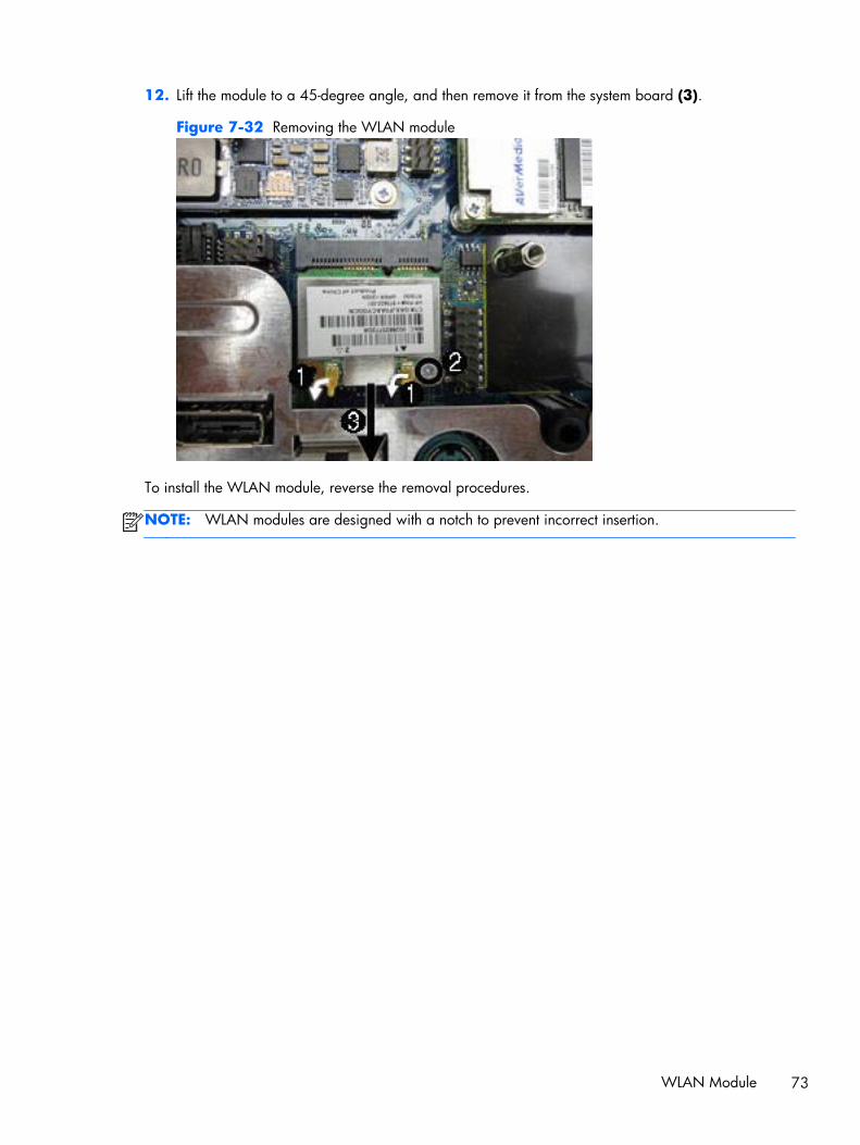
12. Lift the module to a 45-degree angle, and then remove it from the system board (3).
Figure 7-32 Removing the WLAN module
To install the WLAN module, reverse the removal procedures.
NOTE: WLAN modules are designed with a notch to prevent incorrect insertion.
WLAN Module 73

Outer/Left Rear PanelThe outer/left rear panel is secured with two screws. You must pry it off at the seams around the edgesof the computer.
To remove the outer/left rear panel:
1. Prepare the computer for disassembly (see Preparing to Disassemble the Computer on page 42).
2. Remove the small rear cover (see Small Rear Cover on page 43).
3. Remove the port cover (see Port Cover on page 44).
4. Remove the stand (see Stand on page 45).
5. Remove the drive cover (see Optical Drive on page 46).
6. Remove the memory cover (see Memory on page 52).
7. Remove the upper rear panel (see Upper Rear Panel on page 54).
8. Remove the I/O panel (see Rear I/O Cover on page 66).
9. Remove the three screws that secure the panel to the computer.
Figure 7-33 Removing the outer/left rear panel screws
74 Chapter 7 Removal and Replacement Procedures All-in One (AIO) Chassis

10. Using a wedge-type tool, insert the tool in the seams on the sides of the computer and work yourway around, loosening the tabs that secure the front of the computer to the rear.
Figure 7-34 Removing the outer/left rear panel
11. Remove the panel from the computer.
To replace the panel, reverse the removal procedures.
Outer/Left Rear Panel 75

Display Control Board
Description Spare part number
Display control board (brightness board) 643152-001
The display control board is mounted on its side on the left side of the computer. It is secured with twoscrews and has one connector.
Figure 7-35 Display control board location
To remove the display control board:
1. Prepare the computer for disassembly (see Preparing to Disassemble the Computer on page 42).
2. Remove the small rear cover (see Small Rear Cover on page 43).
3. Remove the port cover (see Port Cover on page 44).
4. Remove the stand (see Stand on page 45).
5. Remove the drive cover (see Optical Drive on page 46).
6. Remove the memory cover (see Memory on page 52).
7. Remove the upper rear panel (see Upper Rear Panel on page 54).
8. Remove the I/O panel (see Rear I/O Cover on page 66).
9. Remove the outer/left panel (see Outer/Left Rear Panel on page 74).
10. Remove the two screws that secure the board to the computer (1).
76 Chapter 7 Removal and Replacement Procedures All-in One (AIO) Chassis

11. Disconnect the cable from the board (2).
NOTE: Be careful not to damage the cable when disconnecting it from the board. Do not pull onthe wires.
Figure 7-36 Removing the display control board
12. Remove the board from the computer.
To install the display control board, reverse the removal procedures.
Display Control Board 77

Power Button BoardThe power button board is located on the bottom left side of the computer. It is secured with threescrews and has two connectors.
The power button cable is available using spare part number 643145-001.
Figure 7-37 Power button board location
To remove the power button board:
1. Prepare the computer for disassembly (see Preparing to Disassemble the Computer on page 42).
2. Remove the small rear cover (see Small Rear Cover on page 43).
3. Remove the port cover (see Port Cover on page 44).
4. Remove the stand (see Stand on page 45).
5. Remove the drive cover (see Optical Drive on page 46).
6. Remove the memory cover (see Memory on page 52).
7. Remove the upper rear panel (see Upper Rear Panel on page 54).
8. Remove the I/O panel (see Rear I/O Cover on page 66).
9. Remove the outer/left panel (see Outer/Left Rear Panel on page 74).
10. Remove the tape (1) and three screws (2) that secure the board to the computer.
NOTE: Note the location of the grounding cables for proper replacement.
78 Chapter 7 Removal and Replacement Procedures All-in One (AIO) Chassis

11. Lift the board as far as the cables allow, and then disconnect the two cables from the board (3).
NOTE: Be careful not to damage the cables when disconnecting them from the board. Do notpull on the wires.
Figure 7-38 Removing the power button board
12. Remove the board from the computer.
To install the power button board, reverse the removal procedures.
Power Button Board 79

Inverter BoardThe inverter board is located on the left side of the computer. It is secured with two screws and hasthree connectors.
The inverter power cable is available using spare part number 643158-001.
Figure 7-39 Inverter board location
To remove the inverter board:
1. Prepare the computer for disassembly (see Preparing to Disassemble the Computer on page 42).
2. Remove the small rear cover (see Small Rear Cover on page 43).
3. Remove the port cover (see Port Cover on page 44).
4. Remove the stand (see Stand on page 45).
5. Remove the drive cover (see Optical Drive on page 46).
6. Remove the memory cover (see Memory on page 52).
7. Remove the upper rear panel (see Upper Rear Panel on page 54).
8. Remove the I/O panel (see Rear I/O Cover on page 66).
9. Remove the outer/left panel (see Outer/Left Rear Panel on page 74).
10. Remove the two screws (1) that secure the board to the computer.
80 Chapter 7 Removal and Replacement Procedures All-in One (AIO) Chassis
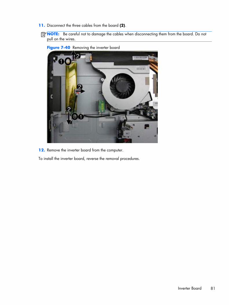
11. Disconnect the three cables from the board (2).
NOTE: Be careful not to damage the cables when disconnecting them from the board. Do notpull on the wires.
Figure 7-40 Removing the inverter board
12. Remove the inverter board from the computer.
To install the inverter board, reverse the removal procedures.
Inverter Board 81

Optical Drive Connector Board
Description Spare part number
Optical drive connector board 643153-001
Optical drive SATA cable 643159-001
Optical drive eject/brightness cable 643146-001
The optical drive connector board is located near the bottom left side of the fan sink. It is secured bytwo screws and has one connector.
Figure 7-41 Optical drive connector board location
To remove the optical drive connector board:
1. Prepare the computer for disassembly (see Preparing to Disassemble the Computer on page 42).
2. Remove the small rear cover (see Small Rear Cover on page 43).
3. Remove the port cover (see Port Cover on page 44).
4. Remove the stand (see Stand on page 45).
5. Remove the drive cover (see Optical Drive on page 46).
6. Remove the memory cover (see Memory on page 52).
7. Remove the upper rear panel (see Upper Rear Panel on page 54).
8. Remove the I/O panel (see Rear I/O Cover on page 66).
9. Remove the outer/left panel (see Outer/Left Rear Panel on page 74).
10. Remove two screws (1) that secure the board to the computer.
82 Chapter 7 Removal and Replacement Procedures All-in One (AIO) Chassis

11. Lift the board to gain easier access to the connector, and then disconnect the cable from the board(2).
NOTE: Be careful not to damage the cable when disconnecting it from the board. Do not pull onthe wires.
Figure 7-42 Removing the optical drive connector board
12. Remove the board from the computer.
To install the optical drive connector board, reverse the removal procedures.
Optical Drive Connector Board 83

Hood Sensor
Description Spare part number
Hood sensor board 643154-001
Hood sensor cable 643149-001
The hood sensor is located just below the fan sink. It is secured with one screw and has one connector.
Figure 7-43 Hood sensor location
To remove the hood sensor:
1. Prepare the computer for disassembly (see Preparing to Disassemble the Computer on page 42).
2. Remove the small rear cover (see Small Rear Cover on page 43).
3. Remove the port cover (see Port Cover on page 44).
4. Remove the stand (see Stand on page 45).
5. Remove the drive cover (see Optical Drive on page 46).
6. Remove the memory cover (see Memory on page 52).
7. Remove the upper rear panel (see Upper Rear Panel on page 54).
8. Remove the I/O panel (see Rear I/O Cover on page 66).
9. Remove the outer/left panel (see Outer/Left Rear Panel on page 74).
10. Remove the tape (1) and screw (2) that secure the board to the computer.
84 Chapter 7 Removal and Replacement Procedures All-in One (AIO) Chassis

11. Lift the connector end of the hood sensor, slide the sensor at an angle toward the large fan toremove it from the tab in the holder, and then remove the sensor from the computer (3).
NOTE: Be careful not to damage the cable when disconnecting it from the connector. Do notpull on the wires.
Figure 7-44 Removing the hood sensor
To install the hood sensor, reverse the removal procedures.
Hood Sensor 85

Hard Drive Connector
Description Spare part number
Hard drive connector cable 658144-001
The hard drive connector is located near the middle of the computer, below the fan. It is secured withtwo screws and has two connectors. The cables are routed under the metal casing to the system boardconnectors.
Figure 7-45 Hard drive connector location
To remove the hard drive connector:
1. Prepare the computer for disassembly (see Preparing to Disassemble the Computer on page 42).
2. Remove the small rear cover (see Small Rear Cover on page 43).
3. Remove the port cover (see Port Cover on page 44).
4. Remove the stand (see Stand on page 45).
5. Remove the drive cover (see Optical Drive on page 46).
6. Remove the memory cover (see Memory on page 52).
7. Remove the upper rear panel (see Upper Rear Panel on page 54).
8. Remove the I/O panel (see Rear I/O Cover on page 66).
9. Remove the outer/left panel (see Outer/Left Rear Panel on page 74).
10. Remove two screws (1) that secure the hard drive connector to the computer.
11. Disconnect the cables from the system board (2).
NOTE: Be careful not to damage the cable when disconnecting it from the board. Do not pull onthe wires.
86 Chapter 7 Removal and Replacement Procedures All-in One (AIO) Chassis

12. Remove the tape that secures the power cable to the computer, and then pull the cables throughthe metal casing (3).
Figure 7-46 Removing the hard drive connector
13. Remove the hard drive connector from the computer.
To install the hard drive connector, reverse the removal procedures.
Hard Drive Connector 87

Fan
Description Spare part number
Fan 644381-001
The fan is located near the top of the computer. It is secured with three screws.
Figure 7-47 Fan location
To remove the fan:
1. Prepare the computer for disassembly (see Preparing to Disassemble the Computer on page 42).
2. Remove the small rear cover (see Small Rear Cover on page 43).
3. Remove the port cover (see Port Cover on page 44).
4. Remove the stand (see Stand on page 45).
5. Remove the drive cover (see Optical Drive on page 46).
6. Remove the memory cover (see Memory on page 52).
7. Remove the upper rear panel (see Upper Rear Panel on page 54).
8. Remove the I/O panel (see Rear I/O Cover on page 66).
9. Remove the outer/left panel (see Outer/Left Rear Panel on page 74).
10. Disconnect the fan cable from the system board connector.
88 Chapter 7 Removal and Replacement Procedures All-in One (AIO) Chassis

11. Remove the three screws that secure the fan to the computer.
Figure 7-48 Removing the fan
12. Lift the fan from the computer.
To install the fan, reverse the removal procedures.
Fan 89

Speakers
Description Spare part number
Speaker, left 644382-001
Speaker, right 644383-001
The speakers are located at the bottom of the computer. Two separate speakers are each secured bytwo screws. The left speaker connects to the right speaker, and the right speaker connects to the systemboard.
Figure 7-49 Speaker location
To remove the speakers:
1. Prepare the computer for disassembly (see Preparing to Disassemble the Computer on page 42).
2. Remove the small rear cover (see Small Rear Cover on page 43).
3. Remove the port cover (see Port Cover on page 44).
4. Remove the stand (see Stand on page 45).
5. Remove the drive cover (see Optical Drive on page 46).
6. Remove the memory cover (see Memory on page 52).
7. Remove the upper rear panel (see Upper Rear Panel on page 54).
8. Remove the I/O panel (see Rear I/O Cover on page 66).
9. Remove the outer/left panel (see Outer/Left Rear Panel on page 74).
90 Chapter 7 Removal and Replacement Procedures All-in One (AIO) Chassis

10. Remove two screws that secure each speaker to the computer.
NOTE: Make note of grounding wire placement for proper installation later.
Figure 7-50 Removing the speakers
11. Remove the tape that secures the speaker wires to the computer.
12. Disconnect the speaker cable from the system board connector.
NOTE: The speakers can be disconnected from each other. The right speaker connects to thesystem board.
To install the speakers, reverse the removal procedures.
System Board ShieldThe system board shield sits above the system board. It is secured with seven screws.
To remove the system board shield:
1. Prepare the computer for disassembly (see Preparing to Disassemble the Computer on page 42).
2. Remove the small rear cover (see Small Rear Cover on page 43).
3. Remove the port cover (see Port Cover on page 44).
4. Remove the stand (see Stand on page 45).
5. Remove the drive cover (see Optical Drive on page 46).
6. Remove the memory cover (see Memory on page 52).
7. Remove the upper rear panel (see Upper Rear Panel on page 54).
8. Remove the I/O panel (see Rear I/O Cover on page 66).
9. Remove the outer/left panel (see Outer/Left Rear Panel on page 74).
10. Remove the small fan (see Small Fan on page 60).
11. Remove the fan (see Fan on page 88).
System Board Shield 91

12. Remove the seven screws that secure the shield to the computer.
NOTE: Ground cables for the inverter, speaker, and webcam module (circled in yellow in theimage) are secured by system board shield screws. If you previously removed these components,these screws have already been removed.
Figure 7-51 Removing the system board shield
13. Lift the shield from the computer.
To install the system board shield, reverse the removal procedures.
92 Chapter 7 Removal and Replacement Procedures All-in One (AIO) Chassis
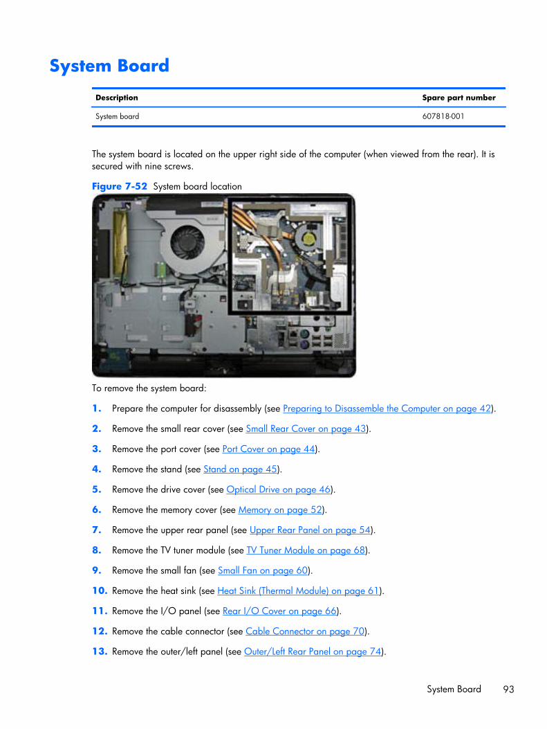
System Board
Description Spare part number
System board 607818-001
The system board is located on the upper right side of the computer (when viewed from the rear). It issecured with nine screws.
Figure 7-52 System board location
To remove the system board:
1. Prepare the computer for disassembly (see Preparing to Disassemble the Computer on page 42).
2. Remove the small rear cover (see Small Rear Cover on page 43).
3. Remove the port cover (see Port Cover on page 44).
4. Remove the stand (see Stand on page 45).
5. Remove the drive cover (see Optical Drive on page 46).
6. Remove the memory cover (see Memory on page 52).
7. Remove the upper rear panel (see Upper Rear Panel on page 54).
8. Remove the TV tuner module (see TV Tuner Module on page 68).
9. Remove the small fan (see Small Fan on page 60).
10. Remove the heat sink (see Heat Sink (Thermal Module) on page 61).
11. Remove the I/O panel (see Rear I/O Cover on page 66).
12. Remove the cable connector (see Cable Connector on page 70).
13. Remove the outer/left panel (see Outer/Left Rear Panel on page 74).
System Board 93

14. Remove the WLAN module (see WLAN Module on page 72).
15. Remove the fan (see Fan on page 88).
16. Remove the graphics board (see Graphics Board on page 64).
17. Remove the system board shield (see System Board Shield on page 91).
18. Disconnect all cables from the system board, noting their location for reinstallation.
19. Remove the nine screws (circled in image) that secure the system board to the computer.
20. Lift the right side of the system board enough so the board clears the posts (shown with arrows inimage), and then remove the system board by lifting up to the right and out of the computer.
Figure 7-53 Removing the system board
To install the system board, reverse the removal procedures.
94 Chapter 7 Removal and Replacement Procedures All-in One (AIO) Chassis

Display PanelNOTE: All display panel spare parts include cable and inverter. Display panel spare parts do notinclude the front bezel.
Description Spare part number
Display panel, 21.5-inch, non-glare, AUO (includes cable and inverter; does not include bezel) 633225-001
Display panel, 21.5-inch, CMO (includes cable and inverter; does not include bezel) 657230-001
Display panel, 21.5-inch, SMG (includes cable and inverter; does not include bezel) 657231-001
Display cable 643157-001
Front bezel 662912-001
The display panel is secured with 14 screws.
To remove the display panel:
1. Prepare the computer for disassembly (see Preparing to Disassemble the Computer on page 42).
2. Remove the small rear cover (see Small Rear Cover on page 43).
3. Remove the port cover (see Port Cover on page 44).
4. Remove the stand (see Stand on page 45).
5. Remove the drive cover (see Optical Drive on page 46).
6. Remove the memory cover (see Memory on page 52).
7. Remove the upper rear panel (see Upper Rear Panel on page 54).
8. Remove the TV tuner module (see TV Tuner Module on page 68).
9. Remove the small fan (see Small Fan on page 60).
10. Remove the heat sink (see Heat Sink (Thermal Module) on page 61).
11. Remove the I/O panel (see Rear I/O Cover on page 66).
12. Remove the cable connector (see Cable Connector on page 70).
13. Remove the outer/left panel (see Outer/Left Rear Panel on page 74).
14. Remove the WLAN module (see WLAN Module on page 72).
15. Remove the fan (see Fan on page 88).
16. Remove the graphics board (see Graphics Board on page 64).
17. Remove the system board shield (see System Board Shield on page 91).
18. Remove the system board (see System Board on page 93).
Display Panel 95

19. Remove the 15 screws that secure the display panel. The number of screws per side is as follows:
● Top: 4 screws
● Bottom: 5 screws
● Left: 3 screws
● Right: 3 screws
20. Lift the display panel from the computer.
Figure 7-54 Removing the display panel
To install a display panel, reverse the removal procedures.
96 Chapter 7 Removal and Replacement Procedures All-in One (AIO) Chassis

A POST Error Messages
This appendix lists the error codes, error messages, and the various indicator light and audiblesequences that you may encounter during Power-On Self-Test (POST) or computer restart, the probablesource of the problem, and steps you can take to resolve the error condition.
POST Message Disabled suppresses most system messages during POST, such as memory count andnon-error text messages. If a POST error occurs, the screen will display the error message. To manuallyswitch to the POST Messages Enabled mode during POST, press any key (except F10, F11, or F12).The default mode is POST Message Disabled.
The speed at which the computer loads the operating system and the extent to which it is tested aredetermined by the POST mode selection.
Quick Boot is a fast startup process that does not run all of the system level tests, such as the memorytest. Full Boot runs all of the ROM-based system tests and takes longer to complete.
Full Boot may also be enabled to run every 1 to 30 days on a regularly scheduled basis. To establishthe schedule, reconfigure the computer to the Full Boot Every x Days mode, using Computer Setup.
97

POST Numeric Codes and Text MessagesThis section covers those POST errors that have numeric codes associated with them. The section alsoincludes some text messages that may be encountered during POST.
NOTE: The computer will beep once after a POST text message is displayed on the screen.
Table A-1 Numeric Codes and Text Messages
Control panel message Description Recommended action
101-Option ROM Checksum Error System ROM or expansion board optionROM checksum.
1. Verify the correct ROM.
2. Flash the ROM if needed.
3. If an expansion board was recentlyadded, remove it to see if the problemremains.
4. Clear CMOS.
5. If the message disappears, there maybe a problem with the expansion card.
6. Replace the system board.
103-System Board Failure DMA or timers. 1. Clear CMOS.
2. Remove expansion boards.
3. Replace the system board.
110-Out of Memory Space for Option ROMs Recently added PCI expansion card containsan option ROM too large to downloadduring POST.
1. If a PCI expansion card was recentlyadded, remove it to see if the problemremains.
2. In Computer Setup, set Advanced >Device Options > NIC PXE OptionROM Download to DISABLE toprevent PXE option ROM for the internalNIC from being downloaded duringPOST to free more memory for anexpansion card's option ROM. InternalPXE option ROM is used for bootingfrom the NIC to a PXE server.
162-System Options Not Set Configuration incorrect.
RTC (real-time clock) battery may need tobe replaced.
Run Computer Setup and check theconfiguration in Advanced > DeviceOptions.
Reset the date and time under ControlPanel. If the problem persists, replace theRTC battery. See the Hardware ReferenceGuide for instructions on installing a newbattery, or contact an authorized dealer orreseller for RTC battery replacement.
98 Appendix A POST Error Messages

Table A-1 Numeric Codes and Text Messages (continued)
Control panel message Description Recommended action
163-Time & Date Not Set Invalid time or date in configuration memory.
RTC (real-time clock) battery may need tobe replaced.
Reset the date and time under ControlPanel (Computer Setup can also be used). Ifthe problem persists, replace the RTCbattery. See the Hardware Reference Guidefor instructions on installing a new battery, orcontact an authorized dealer or reseller forRTC battery replacement.
164-MemorySize Error Memory amount has changed since the lastboot (memory added or removed).
Press the F1 key to save the memorychanges.
164-MemorySize Error Memory configuration incorrect. 1. Run Computer Setup or Windowsutilities.
2. Make sure the memory module(s) areinstalled properly.
3. If third-party memory has been added,test using HP-only memory.
4. Verify proper memory module type.
201-Memory Error RAM failure. 1. Ensure memory modules are correctlyinstalled.
2. Verify proper memory module type.
3. Remove and replace the identifiedfaulty memory module(s).
4. If the error persists after replacingmemory modules, replace the systemboard.
213-Incompatible Memory Module inMemory Socket(s) X, X, ...
A memory module in memory socketidentified in the error message is missingcritical SPD information, or is incompatiblewith the chipset.
1. Verify proper memory module type.
2. Try another memory socket.
3. Replace DIMM with a moduleconforming to the SPD standard.
214-DIMM Configuration Warning Populated DIMM Configuration is notoptimized.
Rearrange the DIMMs so that each channelhas the same amount of memory.
219-ECC Memory Module Detected ECCModules not supported on this Platform
Recently added memory module(s) supportECC memory error correction.
1. If additional memory was recentlyadded, remove it to see if the problemremains.
2. Check product documentation formemory support information.
POST Numeric Codes and Text Messages 99

Table A-1 Numeric Codes and Text Messages (continued)
Control panel message Description Recommended action
301-Keyboard Error Keyboard failure. 1. Reconnect keyboard with computerturned off.
2. Check connector for bent or missingpins.
3. Ensure that none of the keys aredepressed.
4. Replace keyboard.
303-Keyboard Controller Error I/O board keyboard controller. 1. Reconnect keyboard with computerturned off.
2. Replace the system board.
304-Keyboard or System Unit Error Keyboard failure. 1. Reconnect the keyboard with computerturned off.
2. Ensure that none of the keys aredepressed.
3. Replace the keyboard.
4. Replace the system board.
510-Flash Screen Image Corrupted Flash Screen image has errors. Reflash the system ROM with the latest BIOSimage.
511-CPU Fan not Detected CPU fan is not connected or may havemalfunctioned.
1. Reseat CPU fan.
2. Reseat fan cable.
3. Replace CPU fan.
512-Rear Chassis Fan not Detected Rear chassis fan is not connected or mayhave malfunctioned.
1. Reseat rear chassis fan.
2. Reseat fan cable.
3. Replace rear chassis fan.
513-Front Chassis fan not detected Front chassis fan is not connected or mayhave malfunctioned.
1. Reseat front chassis fan.
2. Reseat fan cable.
3. Replace front chassis fan.
912-Computer Cover Has Been RemovedSince Last System Startup
Computer cover was removed since lastsystem startup.
No action required.
917-Front Audio Not Connected Front audio harness has been detached orunseated from motherboard.
Reconnect or replace front audio harness.
921-Device in PCI Express slot failed toinitialize
There is an incompatibility/problem with thisdevice and the system or PCI Express Linkcould not be retrained to an x1.
Try rebooting the system. If the errorreoccurs, the device may not work with thissystem
100 Appendix A POST Error Messages

Table A-1 Numeric Codes and Text Messages (continued)
Control panel message Description Recommended action
1720-SMART Hard Drive Detects ImminentFailure
Hard drive is about to fail. (Some harddrives have a hard drive firmware patch thatwill fix an erroneous error message.)
1. Determine if hard drive is giving correcterror message. Enter Computer Setupand run the Drive Protection System testunder Storage > DPS Self-test.
2. Apply hard drive firmware patchif applicable. (Available athttp://www.hp.com/support.)
3. Back up contents and replace harddrive.
1801-Microcode Patch Error Processor is not supported by ROM BIOS. 1. Upgrade BIOS to proper version.
2. Change the processor.
1802-Processor Not Supported Recently installed processor is not supportedby the system.
Install a processor supported by your system.
1805-Ambient Temperature Previously OverLimit
This system was placed in a low power stateto prevent damage due to excessiveenvironmental temperature.
Make sure the system meets the HP enclosureguidelines as listed in the QuickSpecs,including the following:
1. Clean the air vents on the front, back,or any other vented side of thecomputer.
2. Ensure that there is a 10.2 cm (4 in)clearance on all vented sides of thecomputer to permit the required airflow.
3. Ensure that computers are not so neareach other that they are subject to eachother's re-circulated or preheated air.
4. If the computer is within an enclosure,ensure that there is proper intake andexhaust ventilation for the enclosure.
2200-PMM Allocation Error during MEBxDownload
Memory error during POST execution of theManagement Engine (ME) BIOS Extensionsoption ROM.
1. Reboot the computer.
2. Unplug the power cord, re-seat thememory modules, and reboot thecomputer.
3. If the memory configuration wasrecently changed, unplug the computer,restore the original memoryconfiguration, and reboot the computer.
4. If the error persists, replace the systemboard.
POST Numeric Codes and Text Messages 101

Table A-1 Numeric Codes and Text Messages (continued)
Control panel message Description Recommended action
2201-MEBx Module did not checksumcorrectly
Memory error during POST execution of theManagement Engine (ME) BIOS Extensionsoption ROM.
1. Reboot the computer.
2. Unplug the power cord, re-seat thememory modules, and reboot thecomputer.
3. If the memory configuration wasrecently changed, unplug the powercord, restore the original memoryconfiguration, and reboot the computer.
4. If the error persists, replace the systemboard.
2202-PMM Deallocation Error during MEBxcleanup
Memory error during POST execution of theManagement Engine (ME) BIOS Extensionsoption ROM.
1. Reboot the computer.
2. Unplug the power cord, re-seat thememory modules, and reboot thecomputer.
3. If the memory configuration wasrecently changed, unplug the powercord, restore the original memoryconfiguration, and reboot the computer.
4. If the error persists, replace the systemboard.
2211-Memory not configured correctly forproper MEBx execution
SODIMM1 is not installed. Make sure there is a memory module in theSODIMM1 socket and that it is properlyseated.
2212-USB Key Provisioning failure writing todevice
USB device used for USB key provisioningwill not allow BIOS to update provision fileproperly.
1. Try a different USB key device forprovisioning.
2. If the error persists, update to the latestBIOS version and ME firmware version.
3. If the error still persists, replace thesystem board.
2217-ME Firmware Version request failure ME firmware is not properly responding toBIOS query for version information.
1. Reboot the computer.
2. If the error persists, update to the latestBIOS version and ME firmware version.
3. If the error still persists, replace thesystem board.
2218-ME Firmware Version should beupdated
ME firmware must be updated to matchcurrent functionality contained in the systemBIOS.
1. Update to the latest ME firmwareversion.
2. If the error persists and system BIOShas been recently updated, restoreprevious system BIOS version.
3. If the error still persists, replace thesystem board.
102 Appendix A POST Error Messages

Table A-1 Numeric Codes and Text Messages (continued)
Control panel message Description Recommended action
2219-USB Key Provisioning file has invalidheader identifier
Provisioning file contained on the USB keyhas been corrupted or is not a valid versionfor the current ME firmware.
1. Recreate the provisioning file using thirdparty management console software.
2. If the error persists and system BIOShas been recently updated, restoreprevious system BIOS version.Otherwise, update the ME firmwareversion.
3. If the error still persists, replace thesystem board.
2220-USB Key Provisioning file hasmismatch version
Provisioning file contained on the USB key isnot a valid version for the current MEfirmware.
1. Reboot the computer.
2. If the error persists and system BIOShas been recently updated, restoreprevious system BIOS version.Otherwise, update the ME firmwareversion.
3. If the error still persists, replace thesystem board.
2230-General error during MEBx execution Error occurred during MEBx execution whichfails into the “General” grouping. Statusinformation displayed along with the errorprovides further clarity into the failure. MEBxhandles transference of information betweenthe system BIOS and ME firmware.
1. Reboot the computer.
2. If the error persists, update to the latestBIOS version and ME firmware version.
3. If the error still persists, replace thesystem board.
2231-ME error during MEBx execution Error occurred during MEBx execution whichfails into “ME” grouping.
1. Reboot the computer.
2. If the error persists, update to the latestBIOS version and ME firmware version.
3. If the error still persists, replace thesystem board.
2232-AMT error during MEBx execution Error occurred during MEBx execution whichfails into “AMT” grouping.
1. Reboot the computer.
2. If the error persists, update to the latestBIOS version and ME firmware version.
3. If the error still persists, replace thesystem board.
2233-HECI error during MEBx execution Error occurred during MEBx execution whichfails into “MEI or HECI” grouping.
1. Reboot the computer.
2. If the error persists, update to the latestBIOS version and ME firmware version.
3. If the error still persists, replace thesystem board.
Invalid Electronic Serial Number Electronic serial number is missing. Enter the correct serial number in ComputerSetup.
POST Numeric Codes and Text Messages 103

Table A-1 Numeric Codes and Text Messages (continued)
Control panel message Description Recommended action
Network Server Mode Active and NoKeyboard Attached
Keyboard failure while Network ServerMode enabled.
1. Reconnect keyboard with computerturned off.
2. Check connector for bent or missingpins.
3. Ensure that none of the keys aredepressed.
4. Replace keyboard.
Parity Check 2 Parity RAM failure or a PCI/PCIe device isasserting a SERR#.
Run Computer Setup and Diagnostic utilities.To disable a PCI/PCIe device from assertinga SERR#, run the Computer Setup utility andselect Advanced > Bus Options >SERR# Generation > Disable.
104 Appendix A POST Error Messages
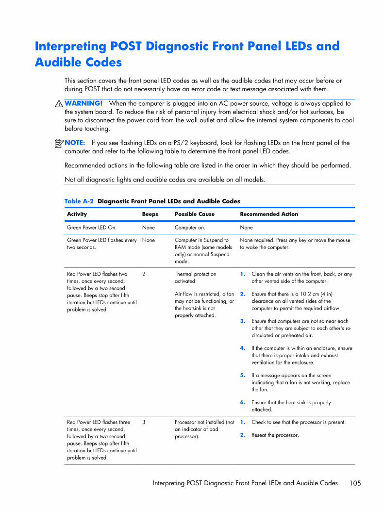
Interpreting POST Diagnostic Front Panel LEDs andAudible Codes
This section covers the front panel LED codes as well as the audible codes that may occur before orduring POST that do not necessarily have an error code or text message associated with them.
WARNING! When the computer is plugged into an AC power source, voltage is always applied tothe system board. To reduce the risk of personal injury from electrical shock and/or hot surfaces, besure to disconnect the power cord from the wall outlet and allow the internal system components to coolbefore touching.
NOTE: If you see flashing LEDs on a PS/2 keyboard, look for flashing LEDs on the front panel of thecomputer and refer to the following table to determine the front panel LED codes.
Recommended actions in the following table are listed in the order in which they should be performed.
Not all diagnostic lights and audible codes are available on all models.
Table A-2 Diagnostic Front Panel LEDs and Audible Codes
Activity Beeps Possible Cause Recommended Action
Green Power LED On. None Computer on. None
Green Power LED flashes everytwo seconds.
None Computer in Suspend toRAM mode (some modelsonly) or normal Suspendmode.
None required. Press any key or move the mouseto wake the computer.
Red Power LED flashes twotimes, once every second,followed by a two secondpause. Beeps stop after fifthiteration but LEDs continue untilproblem is solved.
2 Thermal protectionactivated:
Air flow is restricted, a fanmay not be functioning, orthe heatsink is notproperly attached.
1. Clean the air vents on the front, back, or anyother vented side of the computer.
2. Ensure that there is a 10.2 cm (4 in)clearance on all vented sides of thecomputer to permit the required airflow.
3. Ensure that computers are not so near eachother that they are subject to each other's re-circulated or preheated air.
4. If the computer is within an enclosure, ensurethat there is proper intake and exhaustventilation for the enclosure.
5. If a message appears on the screenindicating that a fan is not working, replacethe fan.
6. Ensure that the heat sink is properlyattached.
Red Power LED flashes threetimes, once every second,followed by a two secondpause. Beeps stop after fifthiteration but LEDs continue untilproblem is solved.
3 Processor not installed (notan indicator of badprocessor).
1. Check to see that the processor is present.
2. Reseat the processor.
Interpreting POST Diagnostic Front Panel LEDs and Audible Codes 105

Table A-2 Diagnostic Front Panel LEDs and Audible Codes (continued)
Activity Beeps Possible Cause Recommended Action
Red Power LED flashes fourtimes, once every second,followed by a two secondpause. Beeps stop after fifthiteration but LEDs continue untilproblem is solved.
4 Power failure (powersupply is overloaded).
1. Open the hood and ensure the 4 or 6-wirepower supply cable is seated into theconnector on the system board.
2. Check if a device is causing the problem byremoving ALL attached devices (such ashard, diskette, or optical drives, andexpansion cards). Power on the system. Ifthe system enters the POST, then power offand replace one device at a time and repeatthis procedure until failure occurs. Replacethe device that is causing the failure.Continue adding devices one at a time toensure all devices are functioning properly.
3. Replace the power supply.
4. Replace the system board.
Red Power LED flashes fivetimes, once every second,followed by a two secondpause. Beeps stop after fifthiteration but LEDs continue untilproblem is solved.
5 Pre-video memory error. CAUTION: To avoid damage to the DIMMs orthe system board, you must unplug the computerpower cord before attempting to reseat, install, orremove a DIMM module.
1. Reseat DIMMs.
2. Replace DIMMs one at a time to isolate thefaulty module.
3. Replace third-party memory with HPmemory.
4. Replace the system board.
Red Power LED flashes sixtimes, once every second,followed by a two secondpause. Beeps stop after fifthiteration but LEDs continue untilproblem is solved.
6 Pre-video graphics error. For systems with a graphics card:
1. Reseat the graphics card.
2. Replace the graphics card.
3. Replace the system board.
For systems with integrated graphics, replace thesystem board.
Red Power LED flashes seventimes, once every second,followed by a two secondpause. Beeps stop after fifthiteration but LEDs continue untilproblem is solved.
7 System board failure(ROM detected failureprior to video).
Replace the system board.
106 Appendix A POST Error Messages

Table A-2 Diagnostic Front Panel LEDs and Audible Codes (continued)
Activity Beeps Possible Cause Recommended Action
Red Power LED flashes eighttimes, once every second,followed by a two secondpause. Beeps stop after fifthiteration but LEDs continue untilproblem is solved.
8 Invalid ROM based onbad checksum.
1. Reflash the system ROM with the latest BIOSimage.
2. Replace the system board.
Red Power LED flashes ninetimes, once every second,followed by a two secondpause. Beeps stop after fifthiteration but LEDs continue untilproblem is solved.
9 System powers on but isunable to boot.
1. Unplug the AC power cord from thecomputer, wait 30 seconds, then plug thepower cord back in to the computer.
2. Replace the system board.
3. Replace the processor.
Red Power LED flashes tentimes, once every second,followed by a two secondpause. Beeps stop after fifthiteration but LEDs continue untilproblem is solved.
10 Bad option card. 1. Check each option card by removing thecard (one at a time if multiple cards), thenpower on the system to see if fault goesaway.
2. Once a bad card is identified, remove andreplace the bad option card.
3. Replace the system board.
Interpreting POST Diagnostic Front Panel LEDs and Audible Codes 107

Table A-2 Diagnostic Front Panel LEDs and Audible Codes (continued)
Activity Beeps Possible Cause Recommended Action
Red Power LED flashes eleventimes, once every second,followed by a two secondpause. Beeps stop after fifthiteration but LEDs continue untilproblem is solved.
11 The current processor doesnot support a featurepreviously enabled on thissystem.
1. Install a TXT capable processor.
2. Disable TXT in the Computer Setup (F10)utility.
3. Reinstall the original processor.
System does not power on andLEDs are not flashing.
None System unable to poweron.
Press and hold the power button for less than 4seconds. If the hard drive LED turns green, thepower button is working correctly and the systemboard needs to be replaced.
OR
Press and hold the power button for less than 4seconds. If the hard drive LED does not turn ongreen then:
1. Check that the unit is plugged into a workingAC outlet.
2. Open hood and check that the power buttonharness is properly connected to the systemboard.
3. Check that both power supply cables areproperly connected to the system board.
4. Check to see if the 5V_aux light on thesystem board is turned on. If it is turned on,then replace the power button harness. If theproblem persists, replace the system board.
5. If the 5V_aux light on the system board isnot turned on, remove the expansion cardsone at a time until the 5V_aux light on thesystem board turns on. It the problempersists, replace the power supply.
108 Appendix A POST Error Messages
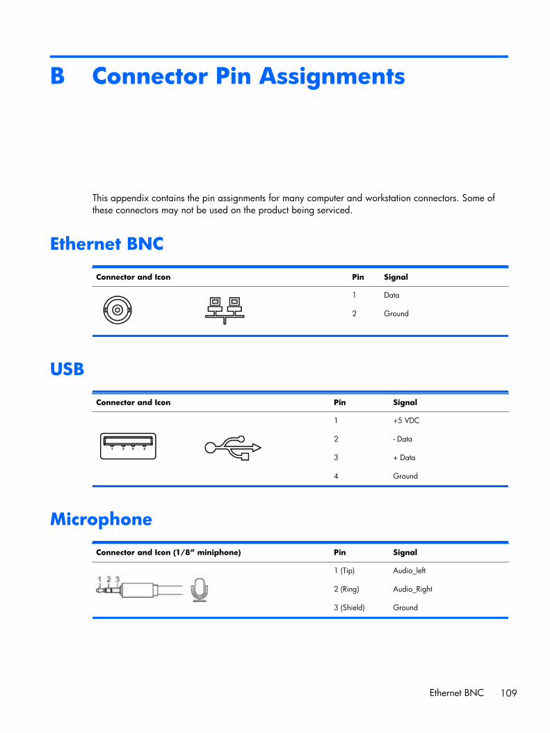
B Connector Pin Assignments
This appendix contains the pin assignments for many computer and workstation connectors. Some ofthese connectors may not be used on the product being serviced.
Ethernet BNC
Connector and Icon Pin Signal
1
2
Data
Ground
USB
Connector and Icon Pin Signal
1
2
3
4
+5 VDC
- Data
+ Data
Ground
Microphone
Connector and Icon (1/8” miniphone) Pin Signal
1 (Tip)
2 (Ring)
3 (Shield)
Audio_left
Audio_Right
Ground
Ethernet BNC 109

Headphone
Connector and Icon (1/8” miniphone) Pin Signal
1 (Tip)
2 (Ring)
3 (Shield)
Audio_left
Power_Right
Ground
Line-in Audio
Connector and Icon (1/8” miniphone) Pin Signal
1 (Tip)
2 (Ring)
3 (Shield)
Audio_In_Left
Audio_In_Right
Ground
Line-out Audio
Connector and Icon (1/8” miniphone) Pin Signal
1 (Tip)
2 (Ring)
3 (Shield)
Audio_Out_Left
Audio_Out_Right
Ground
110 Appendix B Connector Pin Assignments

C Power Cord Set Requirements
The power supplies on some computers have external power switches. The voltage select switch featureon the computer permits it to operate from any line voltage between 100-120 or 220-240 volts AC.Power supplies on those computers that do not have external power switches are equipped withinternal switches that sense the incoming voltage and automatically switch to the proper voltage.
The power cord set received with the computer meets the requirements for use in the country where youpurchased the equipment.
Power cord sets for use in other countries must meet the requirements of the country where you use thecomputer.
General RequirementsThe requirements listed below are applicable to all countries:
1. The power cord must be approved by an acceptable accredited agency responsible for evaluationin the country where the power cord set will be installed.
2. The power cord set must have a minimum current capacity of 10A (7A Japan only) and a nominalvoltage rating of 125 or 250 volts AC, as required by each country’s power system.
3. The diameter of the wire must be a minimum of 0.75 mm2 or 18AWG, and the length of the cordmust be between 1.8 m (6 feet) and 3.6 m (12 feet).
The power cord should be routed so that it is not likely to be walked on or pinched by items placedupon it or against it. Particular attention should be paid to the plug, electrical outlet, and the pointwhere the cord exits from the product.
WARNING! Do not operate this product with a damaged power cord set. If the power cord set isdamaged in any manner, replace it immediately.
Japanese Power Cord RequirementsFor use in Japan, use only the power cord received with this product.
CAUTION: Do not use the power cord received with this product on any other products.
General Requirements 111

Country-Specific RequirementsAdditional requirements specific to a country are shown in parentheses and explained below.
Country Accrediting Agency Country Accrediting Agency
Australia (1)
Austria (1)
Belgium (1)
Canada (2)
EANSW
OVE
CEBC
CSA
Italy (1)
Japan (3)
Norway (1)
Sweden (1)
IMQ
METI
NEMKO
SEMKO
Denmark (1)
Finland (1)
France (1)
Germany (1)
DEMKO
SETI
UTE
VDE
Switzerland (1)
United Kingdom (1)
United States (2)
SEV
BSI
UL
1. The flexible cord must be Type HO5VV-F, 3-conductor, 0.75mm2 conductor size. Power cord set fittings (appliancecoupler and wall plug) must bear the certification mark of the agency responsible for evaluation in the country where itwill be used.
2. The flexible cord must be Type SVT or equivalent, No. 18 AWG, 3-conductor. The wall plug must be a two-polegrounding type with a NEMA 5-15P (15A, 125V) or NEMA 6-15P (15A, 250V) configuration.
3. Appliance coupler, flexible cord, and wall plug must bear a “T” mark and registration number in accordance with theJapanese Dentori Law. Flexible cord must be Type VCT or VCTF, 3-conductor, 0.75 mm2 conductor size. Wall plug mustbe a two-pole grounding type with a Japanese Industrial Standard C8303 (7A, 125V) configuration.
112 Appendix C Power Cord Set Requirements

D Specifications
All-in One ModelsTable D-1 Specifications
Desktop Dimensions
Height
Width
Depth
16.9 in
21.5 in
2.6 in
42.9 cm
54.6 cm
6.6 cm
Approximate Weight 18.2 lb 8.25 kg
Temperature Range
Operating
Nonoperating
41° to 95°F
-22° to 149°F
5° to 35°C
-30° to 66°C
Relative Humidity (noncondensing)
Operating 15-80% at 79°F 15-80% at 26°C
Maximum Altitude (unpressurized)
Operating
Nonoperating
0 - 6,562 ft
0 - 15,000 ft
0 - 2000 m
4,572 m
Power Supply
Rated Voltage Range
Rated Line Frequency
100-240 V
50-60 Hz
100-240 V
50-60 Hz
Max Operating Power <180 W <180 W
Idle Operating Power Integrated graphics: 58 W
Discrete graphics: 66 W
Integrated graphics: 58 W
Discrete graphics: 66 W
All-in One Models 113

Index
AAC adapter
spare part numbers 36, 39audible codes 105
Bbattery
disposal 32beep codes 105blower
spare part number 35, 40Bluetooth module
removing 58spare part number 36, 39
booting optionsFull Boot 97Quick Boot 97
brightness boardspare part number 36, 40
Ccable connector
removing 70cable pinouts
SATA data 23cable, hard drive
spare part number 38, 41cables, spare part numbers 38cautions
AC power 25cables 31electrostatic discharge 26keyboard cleaning 30keyboard keys 30
cleaningcomputer 29mouse 30safety precautions 29
componentsfront 3rear 4side 4
computer cleaning 29connector pin assignments 109country power cord set
requirements 112cover, hard drive
spare part number 35, 40cover, memory
spare part number 35, 40
Ddisplay panel
removing 95spare part number 35, 41spare part numbers 35, 40,
95DisplayPort to HDMI cable
spare part number 38, 39DVD±RW SuperMulti DL Drive with
LightScribespare part numbers 35, 39
Eelectrostatic discharge (ESD) 26
preventing damage 26error
codes 97, 105messages 98
ethernetBNC pin assignments 109
Ffan
removing 88spare part number 35, 40
flashing LEDs 105
front bezelspare part number 35, 41
front components 3
Ggraphics board
removing 64graphics card
spare part numbers 34, 39,40, 41
grounding methods 27
Hhard drive
proper handling 31removing 49, 86SATA characteristics 23spare part numbers 35, 37
hard drive coverspare part number 35, 40
hard drive SATA cablespare part number 38, 41
headphone pin assignments 110heat sink
removing 61heat sink assembly
spare part number 34, 40hood sensor
removing 84hood sensor board
spare part number 36, 40
II/O panel
removing 66inverter
spare part number 35, 41inverter board
removing 80
114 Index

Kkeyboard
cleaning 29spare part numbers 36
LLEDs
blinking power 105blinking PS/2 keyboard 105
line-in audio pin assignments 110line-out audio pin assignments
110
Mmass storage devices, spare part
numbers 37memory cover
spare part number 35, 40memory module
removing 52spare part numbers 34, 38
microphone pin assignments 109mouse
cleaning 30spare part numbers 36
Nnumeric error codes 98
Oopening the computer 42operating guidelines 28optical drive
removing 46spare part numbers 35, 37
optical drive bezel, spare partnumber 36, 41
optical drive boardspare part number 36, 40
optical drive connector boardremoving 82
outer/left rear panelremoving 74
overheating, prevention 28
Pport cover
removing 44spare part number 35, 40
POST error messages 97
postponement door, spare partnumber 35
postponement door; spare partnumber 40
power button boardremoving 76, 78
power control assembly; spare partnumber 35, 40
power cord set requirementscountry specific 112
power supply 113processor
removal and replacementprocedures 62
spare part numbers 34
Rrear components 4rear cover
spare part number 35, 40rear I/O cover
spare part number 35, 40remote control
spare part number 36, 40removal and replacement
processor 62removal and replacement
proceduresAll-in One chassis 42Bluetooth module 58cable connector 70display control board 76display panel 95fan 88graphics board 64hard drive 49hard drive connector 86heat sink 61hood sensor 84inverter board 80memory 52optical drive 46optical drive connector board
82outer/left rear panel 74port cover 44power button board 78preparing to disassemble the
computer 42rear I/O cover 66
small fan 60small rear cover 43speakers 90stand 45system board 93system board shield 91thermal module 61TV tuner module 68upper rear panel 54webcam module 56WLAN module 72
Ssafety precautions
cleaning 29SATA
connectors on system board23
data cable pinouts 23hard drive characteristics 23
screws, correct size 31service considerations 30side components 4small fan
removing 60small rear cover
removing 43software
servicing computer 31spare part number
tamper-resistent wrench 31Torx T-15 screwdriver 31
speakersremoving 90spare part numbers 35, 40
specificationscomputer 113
standremoving 45spare part number 35, 40
stand coverspare part number 35, 40
static electricity 26system board
removing 93SATA connectors 23spare part numbers 34, 39
system board shieldremoving 91
Index 115

Ttamper-proof screws
tool 31tape for WLAN antenna, spare part
number 35, 40temperature control 28thermal module
removing 61thermal module, spare part
number 34, 40tools, servicing 31Torx T15 screwdriver 31TV tuner module
removing 68spare part number 34, 39
Uupper rear panel
removing 54USB pin assignments 109
Vventilation, proper 28
Wwebcam module
removing 56spare part number 34, 39
WLAN moduleremoving 72spare part number 34, 39, 41
116 Index