IMPROVEMENT OF ROLLING CONTACT FATIGUE LIFE BY A PRELIMINARY LOADING IN ELASTIC-PLASTIC DOMAIN
13
1 Copyright © 2008 by ASME Proceedings of the 9th Biennial ASME Conference on Engineering Systems Design and Analysis ESDA08 July 7-9, 2008, Haifa, Israel DRAFT Paper Number: ESDA 2008-59137 IMPROVEMENT OF ROLLING CONTACT FATIGUE LIFE BY A PRELIMINARY LOADING IN ELASTIC-PLASTIC DOMAIN Spiridon Cretu [email protected] Technical University of Iasi, ROMANIA ABSTRACT An analysis model has been developed to model the nonlinear strain rate dependent deformation of rolling bearing steel stressed in the elastic-plastic domain. The model is developed in the frame of the incremental theory of plasticity by using the von Mises yield criterion and Prandtl-Reuss equations. By considering the isotropic and non-linear kinematic hardening laws of Lemaitre-Caboche, the model accounts for the cyclic hardening phenomena. To attain the final load of each loading cycle, the two bodies are brought into contact incrementally. For each new load increment new increments for the components of stress and strain tensors, but also increments of residual stresses, are computed for each point of the 3D mesh. Both, the new contact geometry and residual stresses distributions, are further considered as initial values for the next loading cycle, the incremental technique being reiterated. The cyclic evaluation process of both, plastic strains and residual stresses is performed until the material shakedowns. The experimental part of the paper regards to the rolling contact fatigue tests carried out on two groups of line contact test specimens and on two groups of deep groove ball bearings. In both cases, the experimental data reveal more than two times greater fatigue life for the group with induced residual stresses versus the life of the reference group. The von Mises equivalent stress is considered in Ioannides-Harris rolling contact fatigue model to obtain theoretical lives. The theoretical analysis revealed greater fatigue lives for the test specimens and for the ball bearings groups with induced residual stresses than the fatigue lives of the corresponding reference groups . 1. INTRODUCTION Since the approaches of the cyclic elastic-plastic contact problems by finite element methods are time consuming [1-3, 5, 6], some semi-analytical methods have been recently developed [3-6]. An analysis method, based on an incremental approach, has been previously developed, to model the nonlinear strain rate dependent deformation of rolling bearing steel stressed in the two-dimensional elastic-plastic contact problems, [9, and 10]. An improved version, that considers the isotropic and non-linear kinematic hardening laws of Lemaitre-Caboche,[11], to account for the cyclic hardening phenomena, is presented in the paper for the three-dimensional elastic-plastic contact problems. The improved model proves to be accurate and faster than the finite element method, but also than the semi-analytical methods. 2. MATERIAL AND CONSTITUTIVE EQUATIONS 2.1 Material behavior The material cyclic hardening characteristic is adopted to be described by an isotropic hardening law and the ratchetting effect by a non-linear kinematic hardening law, [11]. For completeness some basic assumptions are presented in the following. The yield surface is defined by the function:
-
Upload
independent -
Category
Documents
-
view
0 -
download
0
Transcript of IMPROVEMENT OF ROLLING CONTACT FATIGUE LIFE BY A PRELIMINARY LOADING IN ELASTIC-PLASTIC DOMAIN

1 Copyright © 2008 by ASME
Proceedings of the 9th Biennial ASME Conference on Engineering Systems Design and Analysis ESDA08
July 7-9, 2008, Haifa, Israel
DRAFT Paper Number: ESDA 2008-59137
IMPROVEMENT OF ROLLING CONTACT FATIGUE LIFE BY A PRELIMINARY LOADING IN ELASTIC-PLASTIC DOMAIN
Spiridon Cretu [email protected]
Technical University of Iasi, ROMANIA
ABSTRACT An analysis model has been developed to model the nonlinear strain rate dependent deformation of rolling bearing steel stressed in the elastic-plastic domain. The model is developed in the frame of the incremental theory of plasticity by using the von Mises yield criterion and Prandtl-Reuss equations. By considering the isotropic and non-linear kinematic hardening laws of Lemaitre-Caboche, the model accounts for the cyclic hardening phenomena. To attain the final load of each loading cycle, the two bodies are brought into contact incrementally. For each new load increment new increments for the components of stress and strain tensors, but also increments of residual stresses, are computed for each point of the 3D mesh. Both, the new contact geometry and residual stresses distributions, are further considered as initial values for the next loading cycle, the incremental technique being reiterated. The cyclic evaluation process of both, plastic strains and residual stresses is performed until the material shakedowns. The experimental part of the paper regards to the rolling contact fatigue tests carried out on two groups of line contact test specimens and on two groups of deep groove ball bearings. In both cases, the experimental data reveal more than two times greater fatigue life for the group with induced residual stresses versus the life of the reference group. The von Mises equivalent stress is considered in Ioannides-Harris rolling contact fatigue model to obtain theoretical lives. The theoretical analysis revealed greater fatigue lives for the test specimens and for the ball bearings groups with induced
residual stresses than the fatigue lives of the corresponding reference groups . 1. INTRODUCTION Since the approaches of the cyclic elastic-plastic contact problems by finite element methods are time consuming [1-3, 5, 6], some semi-analytical methods have been recently developed [3-6]. An analysis method, based on an incremental approach, has been previously developed, to model the nonlinear strain rate dependent deformation of rolling bearing steel stressed in the two-dimensional elastic-plastic contact problems, [9, and 10]. An improved version, that considers the isotropic and non-linear kinematic hardening laws of Lemaitre-Caboche,[11], to account for the cyclic hardening phenomena, is presented in the paper for the three-dimensional elastic-plastic contact problems. The improved model proves to be accurate and faster than the finite element method, but also than the semi-analytical methods. 2. MATERIAL AND CONSTITUTIVE EQUATIONS 2.1 Material behavior The material cyclic hardening characteristic is adopted to be described by an isotropic hardening law and the ratchetting effect by a non-linear kinematic hardening law, [11]. For completeness some basic assumptions are presented in the following. The yield surface is defined by the function:

2 Copyright © 2008 by ASME
( ) 00 =−−= YfF σασ (1) Where ( )ασ −f is the equivalent von Mises stress with respect to the back-stressα , and defined as?
( ) ( ) ( )devdev SSf ααασ −−=− :23
(2)
The isotropic hardening component of the model defines the equivalent stress as a function of the equivalent plastic strain and for materials that cyclically harden is modelled with a simple exponential law as:
⎟⎠⎞⎜
⎝⎛ −+= ∞
pb
YY eQ εσσ 0100 (3)
The isotropic hardening parameters ∞Q and ∞b can be calibrated from uniaxial tensile stress-strain curves when kinematic hardening component is neglected. The non-linear kinematic hardening component describes the ratchetting effect by expressing the translation of the yield surface in the stress space through the back-stress. The non-linear kinematic hardening component in fact is characterized by unsymmetrical cycles of stress caused by ratchetting effect in the direction of the mean stress. This law is presented as an additive combination of a linear term and a relaxation term, which introduces the non-linearity. Integration of the kinematic hardening for monotonic loading in one-dimension gives the following expression for the back-stress:
( )p
eC εγ
γα −−= 1 (4)
The kinematic hardening parameters C and γ can be determined when the isotropic hardening parameters ∞Q and ∞b are assigned zero values. The link between the intensity of the stress tensor and the intensity of the strain tensor is assured by the Ramberg-Osgood’s equation:
Nee
e BE⎟⎠⎞
⎜⎝⎛ σ+
σ=ε (5)
2.2 Constitutive equations The increment of the total strain is assumed to be a sum of the elastic and plastic strain increments: pe ddd ε+ε=ε (6)
Hooke’s law provides the differential of elastic strain tensor:
[ ]ijkkijeij dd
Ed δσνσνε ⋅⋅−⋅+= )1(1
(7)
The differential of plastic strain tensor is:
Sd23d
e
pep ⋅
σε
=ε (8)
The differential of the strain tensor becomes:
( )[ ] ee
kkijijij dH
SddE
d σσ
σνδσνε⋅′
+−+=2311
(9)
where: ( ) 1N
e
N
NBH −σ
=′
Differentiating the intensity of the stress tensor, the increments of the total strain are obtained, as follows:
( )[ ]
( )[ ]klklklkkkke
ij
kkijijij
ddSSH
S
ddE
d
σσδσ
σνδσνε
−+′
+−+=
1149
11
2
(10)
In the matrix notation:
[ ] σε dBd ⋅= and [ ] εσ dAd ⋅= [ ] [ ] 1−= BA (11) 3. INCREMENTAL LOADING IN ELASTIC- PLASTIC DOMAIN 3.1 Numerical algorithm The algorithm starts from a sufficiently low load level to induce in the entire half-space an elastic stresses state. The pressure distribution is numerically obtained as the solution of the linear algebraic system formed with Boussinesq’s equation written in all mesh points of the candidate contact area, [12-14]. More details are given in the Appendix 1. To attain the final load, the two bodies are brought into contact incrementally, and for each new load increment the new pressure distribution is obtained as the solution of a constrained system of equations. For each load level the internal stresses state is found by using the superposition principle, see the Appendix 2.

3 Copyright © 2008 by ASME
The von Mises yield condition is checked in each point of the 3D mesh. At a certain load increment order, ,1+n the yield condition is fulfilled in a number of points inside the stressed volume and the plastic deformation takes place. For each of these points the stress and strain tensors are obtained in three steps. In the first step, the increment of the stress tensor is evaluated as a difference between the successive order components while the increment of the total deformation tensor is evaluated by the equation (7), (compatibility technique):
( ) ( )nnnd σσσ −= ++ 1)1( (12)
[ ]δσνσνε ⋅⋅−⋅+= +++ )1()1()1( )1(1 nnn ddE
d
(13) In the second step, the increment of the stress tensor is recalculated involving equation (11):
[ ] )1()()1( ++ ⋅= nnn dAd εσ (14)
The increments of the elastic and plastic strains are founded as:
( ) [ ]ijn
kkn
ijne
ij ddE
d δσνσνε ⋅⋅−⋅+= +++ )1()1()1( )1(1
( ) ( ) )1()1()1( +++−=
nennp ddd εεε (15, 16) Versus the previous incremental algorithms [9, 10], the increments of residual stresses are evaluated in this approach:
( ) ( ) ⎥⎦⎤
⎢⎣⎡ +⋅++
=+++∗ 11)1(
11np
ijijnp
kkn
R ddEd εδεν
νν
σ
)1*()1*()1(
1+++
−−= n
zzRn
xxRn
xxR ddd σν
νσσ
)1*()1*()1(
1+++
−−= n
zzRn
yyRn
yyR ddd σν
νσσ (17)
In the third step, the residual stresses increments are added to the stresses increments:
)1()1()1( +++ += nR
nn ddd σσσ (18) Finally, for the involved point, the stress and strain tensors are:
)1()()1( ++ += nnn dσσσ
(19)
)1()()1( +++=
npnpnp dεεε (20) The evaluation process, of both plastic strains and residual stresses, is performed in all points of the loaded half-space. As long as the load attains its final value, the integration of the plastic strains provides the plastic displacements and changes of the contact geometry. Both, the new contact geometry and residual stresses distributions, are further considered as initial values for the next loading cycle, the incremental technique being reiterated. The cyclic incremental technique continues till material shakedowns. 3.2 Comparison with alternative simulations The results obtained with the incremental technique have been compared with results provided either by the finite element method or by more sophisticated semi-analytical codes. In this respect, the case of an elastic-plastic body in contact with a rigid punch, recently analyzed by Jacq and Nelias, [3], as well as by Wang and Keer, [5], has been considered.
Figure 1: Distribution of residual displacement on the along the axis of the contact area The distribution of the residual displacement
zu along the axis of the contact area as presented in figure1, is quite similar with the corresponding distribution obtained by Wang and Keer, ([5] - figure 17), but with a more elaborate semi-analytical method. For the same case, the depth distributions of the residual stresses obtained by using the incremental technique are presented in figure 2 and figure 3. These distributions proved to be identical with those obtained by using both a semi-analytical method

4 Copyright © 2008 by ASME
and the finite element method, Jacq and Nelias, ([3] - figure 14 and figure 16).
Figure 2: Residual stress versus depth along the z axis
Figure 3: Residual stresses profile at 2 microns far from the contact axis.
3.3 Comparison with measurements By using the X-ray technique, Muro and co-authors , [13], presented the distribution of the residual stresses developed in the shallow layer of a rolling line contact loaded in elastic – plastic domain. In figure 4 are presented comparatively the measured depth distribution of circumferential residual stresses as presented in [13] and the distributions of residual stresses obtained by using the incremental technique. The data obtained numerically correlate quite well with the measured values and point out the evolution of residual stresses with the increase of number of loading cycles, as well as the fact that the material shakesdown.
Figure 4: The depth distribution of circumferential residual stresses: numerical versus measured. 4. EXPERIMENTAL STUDY ON TEST SPECIMENS 4.1 Test specimens and method to induce residual stresses
Two groups of inner rings of NU206 cylindrical roller bearing were subjected to rolling contact fatigue, the reference group without any induced residual stresses and the second group with an induced state of residual stresses.
To eliminate both the geometrical and micro-structural changes, the residual stresses state was induced in the shallow layer of the cylindrical test specimens by loading, each test specimen, in line contact at a load level corresponding to elastic-plastic domain, ( GPaH 5.5=σ ). To produce micro-structural changes which are visible by light microscopy more than one million loading cycles are required [15]. For the chosen case of the line contact loading, the radii of curvature in principal planes are not changed, and because the number of cycles was sufficiently small (200 cycles), the only changes which could appear were in the residual stresses state.
4.2 Fatigue life tests
To eliminate the influence of the edge concentrators the fatigue life tests were further performed in point contact loading, ( ,4GPaH =σ
55.0=β ), on a testing machine where the test specimens were situated between three identical toroidal discs, figure 5. The raceway roughness was
mRa μ06.0= for the test specimens and
mRa μ16.0= for the toroidal discs. The
lubrication parameter was .8.3=λ
5 Copyright © 2008 by ASME
Figure 5: Test specimen loading
4.3 Fatigue life results
The Weibull distribution function was hypothesized as describing the distribution of fatigue lives and the maximum likelihood method was used to estimate the parameters of each distribution group.
The specimen group with induced residual stresses provided more than two times greater fatigue lives comparing with the fatigue life of the reference group, figure 6 and the Table 1.
Figure 6: Weibull plots of the fatigue failed test specimens
Table 1 Fatigue life results for test specimens
Fatigue lives (relative values)
Group
Prestressing
stress Pσ
( )GPa 10L mL
E-1 0 25.5 55
E-2 4.5 55 135
4.4 Theoretical lives estimation
To estimate the theoretical values of fatigue lives for each ball-bearing group, the Ioannides-Harris fatigue life model [11] was applied, with the depth weighting removed, as it was suggested by Lubrecht, Jacobson and Ioannides, [12]. According to Ioannides and Harris the fatigue life L (millions of stress cycles) and the related reliability S are calculated from:
( )
e
V
cu dVA
SL
/1
.*
1ln
⎥⎥⎥⎥
⎦
⎤
⎢⎢⎢⎢
⎣
⎡
−
⎟⎠⎞
⎜⎝⎛
=∫ σσ
(19)
( )[ ]∫ ⋅−⋅⋅−=V
cu
e dVLAS σσexp (20)
What is concern in this study is not the absolute
fatigue life but the relative live, which is the life L divided by a reference life , both of which refer to the same reliability:
( )( )
e
V
cu
V
c
uref
refdV
dVrefL ref
/1
)(⎥⎥⎥
⎦
⎤
⎢⎢⎢
⎣
⎡
⋅−
⋅−=
∫∫
σ
σσ
σσ (21)
The von Mises equivalent stress, capable to
include both elastic and residual stresses, is suitable to be the stress used for reference life computation, Popinceanu, Diaconescu, Cretu, [13].
4.5 Residual stresses and shakedown The depth distribution of residual streses
induced in the shallow layer of the prestressed test specimens are presented in figure 7 for the circumferential direction and figure 8 for the axial direction.

6 Copyright © 2008 by ASME
Figure 7: Residual stresses distribution in the circumferential direction
Figure 8 : Residual stresses distribution in the axial distribution
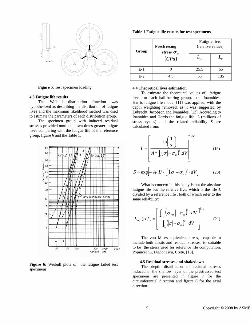
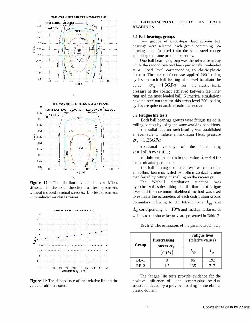
The distributions of the von Mises stresses are comparatively presented in figure 9 for the circumferential direction and figure 10 for the axial direction. The value obtained for the relative life depends on the value considered for the ultimate stress uσ , Figure 11 and reveals again more than two times greater fatigue lives for the specimen group with induced residual stresses.
a
b Figure 9 : The distributions of the von Mises stresses in the circumferential direction: a –test specimens without induced residual stresses; b - test specimens with induced residual stresses.
7 Copyright © 2008 by ASME
a
b
Figure 10 : The distributions of the von Mises stresses in the axial direction: a –test specimens without induced residual stresses; b - test specimens with induced residual stresses.
Figure 11: The dependence of the relative life on the value of ultimate stress.
5. EXPERIMENTAL STUDY ON BALL BEARINGS 5.1 Ball bearings groups
Two groups of 6308-type deep groove ball bearings were selected, each group containing 24 bearings manufactured from the same steel charge and using the same production series.
One ball bearings group was the reference group while the second one had been previously preloaded at a load level corresponding to elastic-plastic domain. The preload force was applied 200 loading cycles on each ball bearing at a level to attain the value GPaH 5.4=σ for the elastic Hertz pressure at the contact achieved between the inner ring and the most loaded ball. Numerical simulations have pointed out that the this stress level 200 loading cycles are quite to attain elastic shakedown. 5.2 Fatigue life tests
Both ball bearings groups were fatigue tested in rolling contact by using the same working conditions:
-the radial load on each bearing was established a level able to induce a maximum Hertz pressure
GPa35.30 =σ ; -rotational velocity of the inner ring
.min/1500revn = ; -oil lubrication to attain the value 8.4=λ for
the lubrication parameter; -the ball bearing endurance tests were run until
all rolling bearings failed by rolling contact fatigue manifested by pitting or spalling on the raceways.
The Weibull distribution function was hypothesized as describing the distribution of fatigue lives and the maximum likelihood method was used to estimate the parameters of each distribution group. Estimators referring to the fatigue lives 10L and
mL corresponding to %10 and median failures, as well as to the shape factor e are presented in Table 2.
Table 2. The estimators of the parameters L10, Lm
Fatigue lives (relative values)
Group
Prestressing
stress Pσ
( )GPa 10L mL
BB-1 0 86 193 BB-2 4.5 135 717
The fatigue life tests provide evidence for the
positive influence of the compressive residual stresses induced by a previous loading in the elastic-plastic domain.

8 Copyright © 2008 by ASME
5.3 Residual stresses and shakedown For the case of the preloaded ball bearings, the
distributions of the normal residual stresses achieved after the 1st, 2nd, 10th, 60th, 90th and 100 loading cycles are presented in figure 12 for the circumferential direction and in figure 13 for the axial direction.
Figure 12: Depth distribution of the normal circumferential residual stress
Figure 13: Depth distribution of the normal axiall residual stress
The diagrams presented in figure 12 and figure 13 point out that the shakedown process has been attained. After 100 loading cycles the residual stresses distributions are the same with those attained at 90 loading cycles that suggests that the residual stresses distribution have no evolution as long as the number of cycles is greater than 90.
5.4 Theoretical lives The residual stresses attained in the shakedown process have been further considered to obtain the new von Mises distributions, which were further considered in Ioannides-Harris approach of life calculations. The theoretical analysis reveals 3.09 greater fatigue life for the group with induced residual stresses versus the fatigue life of the reference group. 6. CONCLUSIONS 1. An analysis model has been developed to model the nonlinear strain rate dependent deformation of rolling bearing steel stressed in the elastic-plastic domain. By considering the isotropic and non-linear kinematic hardening laws of Lemaitre-Caboche, the model accounts for the cyclic hardening phenomena. The model is developed in the frame of the incremental theory of plasticity by using the von Mises yield criterion and Prandtl-Reuss equations. To consider the material behavior the Ramberg-Osgood stress-strain equation is involved and a nonlinear equation is considered to model the influence of the retained austenite. To attain the final load of each loading cycle the two bodies are brought into contact incrementally, so that for each new load increment the new pressure distribution is obtained as the solution of a constrained system of equation. 2 .Comparisons of the computed deformed profiles as well as of the computed residual stresses distributions with those presented in literature and obtained by measurements or numerically by using the finite element method or another semi-analytical method, reveal a good agreement and validate the analysis model. 3. Two groups of line contact test specimens and on two groups of deep groove ball bearings were fatigue life tested. In both cases, the experimental data reveal more than two times greater fatigue life for the group with induced residual stresses versus the life of the reference group. 4. The von Mises equivalent stress was considered in Ioannides-Harris rolling contact fatigue model to obtain theoretical lives. The theoretical analysis revealed more than twoo times greater fatigue lives for the test specimens and for the ball bearings groups with induced residual stresses than the fatigue lives of the corresponding reference groups . 5.Both, the experimental work and the theoretical analysis, validate the beneficial influence of the

9 Copyright © 2008 by ASME
compressive residual stresses induced by a previous contact loading in the elastic-plastic domain. Nomenclature [ ]A – Tensor revealing the stress increments by strain
[ ]B – tensor revealing the strain increments by stress A – proportionality constant B - material constant C – kinematic hardening modulus E – Young’s modulus
'H - equivalent plasticity modulus N – parameter of strain hardening
∞Q - material parameter defining the maximum change in the size of the elastic range S – deviatoric stress tensor
∞b - material parameters defines the rate at which the elastic range develops α - back-stress
devα - deviatoric part of the back-stress tensor δ - Kronecker’s tensor γ - rate at which kinematic hardening modulus decreases as plastic deformation develops ε - strain tensor
eε - strain intensity p
ε - equivalent plastic strain εd - strain increment tensor
ν - Poisson’s ratio σ - stress tensor σd - stress increment tensor
eσ - stress intensity
Hσ - maximum Hertz pressure
Eσ , 0Yσ - yield stress at zero plastic strain 0Yσ - current yield stress
Superscripts e – elastic n – iteration order p – plastic
Subscripts i, j, k, l - components
Appendix 1: ELASTIC PRESSURE DISTRIBUTION
In the absence of load the two smooth contacting surfaces have an initial contact point where a common tangent plane and a common normal exist. The normal load deflects inwards the contacting surfaces to a common contact area, named the real contact area and denoted by Ar. The shape and size of the real contact area, as well as the pressure distribution on it are unknowns. For the contact of rough surfaces, the real contact area can be a system of isolated areas ari :
(A1)
A hypothetical rectangular contact area, denoted hA is built on the common tangent plane, around the initial contact point. The hypothetical contact area is chosen large enough to overestimate the unknown real contact area, rh AA ≥ . A Cartesian system ( x, y, z ) is introduced, its x-O-y plane being the common tangent plane and with its origin located at the left corner of the hypothetical rectangular area. The elastic deflection of each surface is measured in the direction of the corresponding outer normal and is denoted by wI( x, y ) and wII( x, y ), respectively. The sum of the individual deflections at the point ( x, y ) is defined as composite deflection, denoted by w( x, y ). The model of surface deformation is defined by the following three equations: a) the geometric equation of the elastic contact :
0),(),(),( δ−+= yxwyxhyxg (A2) which express the value of the gap between surfaces after deformation as a sum between their initial separation at first contact when no load is applied h( x, y ), the composite elastic deformation w( x, y ), and the rigid approach of the bodies 0δ ; b) the integral equation of the normal surface displacement of the elastic half-space:
( ) ηξηξ
ηξυυπ
ddyx
pEE
yxwrA
II
II
I
I ∫∫−+−
−+
−=
22
22
)()(),(111),(
(A3) where: EI, EII , ,, III υυ are Young’s modulus and Poisson’s ratio for the elastic materials, and
ri
ri Aa =∑

10 Copyright © 2008 by ASME
p( x, y ) is the interfacial contact pressure; c) the load balance equation:
∫ =rA
Qdxdyyxp ),( , (A4)
where Q is the applied normal force. The constraints of non-adhesion and non-penetration must be fulfilled:
,0),( =yxg ),( yxp >0, rAyx ∈),( (A5)
,0),( >yxg ),( yxp =0, rAyx ∉),( (A6) As long as the pressure distribution is known, to obtain the subsurface stresses we have to solve the Neumann’s problem for the elastic half-space. For non-Hertzian concentrated contacts there are not available analytic solutions , so that a discrete presentation of the problem becomes necessary. A uniformly spaced rectangular array is built on the hypothetical rectangular contact area with the grid sides parallel to the x and y-axes. The nodes of the grid are denoted by ( i, j ), where indices i and j refer to the grid columns and rows, respectively. In the considered Cartesian system, the coordinates of the grid node ( i, j ) are denoted by ( xi, yj ) and are given by xixi Δ∗= , )0( Nxi <≤ and
yjy j Δ∗= , ( Nyj <≤0 ) where xΔ and yΔ
are the grid spacings in the x and y-directions, respectively. The real pressure distribution is approximated by a virtual pressure distribution, a piecewice-constant approximation between grid nodes being typically used. The analytic formulation, represented by equations (A2) - (A6) is replaced by the discrete equations (A7) - (A11) :
0δ−+−= ijijijij wRhg , (A7)
,,
1
0
1
0klljki
Ny
l
Nx
kij pKw −−
−
=
−
=∑∑= (A8)
Fpyx ij
Ny
j
Nx
i
=ΔΔ ∑∑−
=
−
=
1
0
1
0
(A9)
,0=ijg ,0>ijp rAji ∈),( (A10)
,0>ijg ,0=ijp rAji ∉),( (A11)
The influence function Kij describes the deformation of the discretised surface due to a unit pressure acting in element (k,l). The coefficients Kij are found by integrating the Boussinesq equation for a patch load represented by a unit pressure acting normally over the element of area yxΔΔ .
∫ ∫−+−⎟⎟
⎠
⎞⎜⎜⎝
⎛ −+
−=
2
1
2
122
22
,)()(
1111 y
y
x
x jiII
II
I
Iij dd
yxEEK ηξ
ηξ
υυπ
(A12) The integral in Eq. (A12) gives
( )2,1()2,2()1,1(111 22
yxfyxfyxfEE
KII
II
I
Iij −+⎟⎟
⎠
⎞⎜⎜⎝
⎛ −+
−=
υυπ
(A13) where: the function f( x, y ) has the form :
( ) ( )2222 lnln),( yxxyyxyxyxf +++++= (A14) and ,2/1 xxx k Δ−= 2/2 xxx k Δ+= ,
,2/1 yyy l Δ−= .2/2 yyy l Δ+= The Conjugate Gradient Method,( CGM) has been chosen to solve the mentioned algebraic system of equations. In respect to other iterative methods the CGM has important advantages: there exists a rigorous mathematical proof of the method convergence; offers a very high rate of convergence (super-linear); requires very modest storage capacity, (the memory requirements grows proportional with the number of points). There is a significant computational advantage of viewing the displacement w as a convolution of pressure p with elastic response K. The discrete convolution with the process of zero padding and wrap-around order can help avoid completely any error associated with FFT at a cost only doubling the domain dimensions of a contact problem. The final iterative process for real areas and pressure distribution has some distinctive particularities, as follows: - the contact area is established in the course of the pressure iteration, so that, there is no need for further iteration with respect to the contact area; - the force balance equation is enforced during each iteration for the contact pressure evaluation.

11 Copyright © 2008 by ASME
Appendix 2: ELASTIC STRESSES STATE The stresses induces in M(x,y,z) are obtained by using the superposition principle:
∑∑−
=
−
=
=1
0
1
0),,(
Nx
k
Ny
lklijklij pCzyxσ (A15)
where the influence function ),,( zyxCijkl describes
the stress component ),,( zyxijσ due to a unit
pressure acting in patch (k,l). This is a Neumann type problem of the elastic halfspace. The coefficients
),,( zyxCijkl were found by integrating the
equations (A3) for a patch load represented by a unit pressure acting normally over the element of area yxΔΔ . References [1] Jiang, Y., Xu, B., Sehitoglu, H., 2002,
“Three-Dimensional Elastic-Plastic Stress Analysis of Rolling Contact”, ASME J. Tribol.y, 124, pp. 699-708.
[2] Chen, Q., Hahn, G.T., Rubin, C.A., Bhargava,
V., 1988, The Influence of Residual Stresses on Rolling Contact Mode II Driving Force in Bearing Raceway”, Wear, 26, pp. 17-30.
[3] Jacq, C., Nelias, D., Lormand, G., Girodin,
D., 2002, “Development of Three-Dimensional Semi-Analytical Elastic-Plastic Contact Code”, ASME J. Tribol. , 124, pp653-667.
[4] Antaluca, E., Nelias, D., Cretu, S., 2004, “A
Three-Dimensional Friction Model for Elastic Plastic Contact with Tangential Loading – Application to Dented surfaces”, ASME/STLE IJTC, Long Beach, paper 64331.
[5] Wang F., Keer L., 2005, „ Numerical
Simulation for Three Dimensional Elastic-Plastic Contact with Hardening Behavior”, ASME J. Tribol.,127, pp.494-502.
[6] Nelias D., Antaluca E., Boucly V., Cretu S.,
2007, “A Three-Dimensional Semianalytical Model for Elastic-Plastic Sliding Contacts”, ASME J. Tribol., 129, pp. 761-771.
[9] Palazotto, N.A., Morris, N.F., 1971, “An elastic –Plastic Plane Stress Solution Using the Incremental Theory”, Int. J. of Mech. Sci., 13, pp. 97.
[10] Cretu, S., Hatmanu, V., 1985, “ A Numerical
Analysis of Permanent Deformation in Elastic-Plastic Line Contact”, Bul. Inst. Polit. Iasi, XXXI, (1-4), pp. 19-25.
[11] Lemaitre, J., Chaboche, J., 1990, “Mechanics of
Solid Materials”, Cambridge University Press, pp. 161-241.
[12] Allwood, J., 2005, “Survey and Performance
Assessment of Solution Method for Elastic Rough Contact Problems”, ASME J. Tribol., 127, pp. 10-23.
[13] Cretu S.S., 2005„Pressure Distributions in
Concentrated Rough Contacts – Part I Theoretical Formulations and NumericalAlgorithm ’’, Bull. Inst.Polit. Iasi, LI(LV), s. CM,1-2, pp.1-18.
[14] Cretu S.S.,2005 „Pressure Distributions in
Concentrated Rough Contacts – Part II Contact Solver Algorithm, Examples and Discussions ’’, Bull. Inst. Polit. Iasi, LI(LV), s. CM,1-2, pp. 19-31.
[15] Muro H., Tsushima N., Nunome M., 1973,
„Initiation of Surface Cracks in Rolling Fatigue of High Hardness Steel”, WEAR, 35, (2),pp.261-282.

12 Copyright © 2008 by ASME

13 Copyright © 2008 by ASME