Improved fuzzy logic controller for SVC in power system damping using global signals
11
This article was published in the above mentioned Springer issue. The material, including all portions thereof, is protected by copyright; all rights are held exclusively by Springer Science + Business Media. The material is for personal use only; commercial use is not permitted. Unauthorized reproduction, transfer and/or use may be a violation of criminal as well as civil law. ISSN 0948-7921, Volume 91, Number 7
-
Upload
kalasalingam -
Category
Documents
-
view
0 -
download
0
Transcript of Improved fuzzy logic controller for SVC in power system damping using global signals

This article was published in the above mentioned Springer issue.The material, including all portions thereof, is protected by copyright;all rights are held exclusively by Springer Science + Business Media.
The material is for personal use only;commercial use is not permitted.
Unauthorized reproduction, transfer and/or usemay be a violation of criminal as well as civil law.
ISSN 0948-7921, Volume 91, Number 7

Electr Eng (2010) 91:395–404DOI 10.1007/s00202-010-0148-4
ORIGINAL PAPER
Improved fuzzy logic controller for SVC in power system dampingusing global signals
N. Karpagam · D. Devaraj · P. Subbaraj
Received: 16 June 2009 / Accepted: 28 January 2010 / Published online: 16 February 2010© Springer-Verlag 2010
Abstract Static Var Compensator (SVC) is a shunt-typeFACTS device, which is used in power systems primarilyfor the purpose of voltage and reactive power control. In thispaper, an improved fuzzy logic-based supplementary con-troller for SVC is developed for damping the rotor angleoscillations and to improve the stability of the power system.The generator speed and the electrical power are chosen asglobal input signals for the proposed fuzzy logic controller(FLC). The effectiveness and feasibility of the proposed con-trol is demonstrated with single-machine infinite bus (SMIB)system, three-machine nine-bus WSCC system and NewEngland 10-machine system, which shows the improvementover the use of a fixed parameter controller and existing FLC.
Keywords FLC · SVC · Transient stability · SMIB ·PID controller
1 Introduction
Power system stability is the ability of the system to regain itsoriginal operating conditions after a disturbance to the sys-tem. Power system transient stability analysis is consideredwith large disturbances like sudden change in load, gener-ation or transmission system configuration due to fault orswitching [1]. Dynamic voltage support and reactive powercompensation have been identified as very significant mea-sures to improve the transient stability of the system. FlexibleAC Transmission Systems (FACTS) devices with a suitablecontrol strategy have the potential to increase the system sta-bility margin [2,3]. In large power systems, low-frequency
N. Karpagam (B) · D. Devaraj · P. SubbarajKalasalingam University, Anand Nagar, Krishnankoil 626190, Indiae-mail: [email protected]
electromechanical oscillations often follow the electrical dis-turbances. Generally, power system stabilizers (PSS) are usedin conjunction with automatic voltage regulators (AVRs) todamp out the oscillations [3]. However, during some operat-ing conditions, this device may not produce adequate damp-ing and other effective alterations are needed in addition toPSS [4,5]. One such alternative means to achieve damping isto use the Static Var Compensator (SVC) designed with aux-iliary controllers [6]. SVC is a shunt FACTS device, whichplays an important role in reactive power flow in the powernetwork. The SVC, if accommodated with a supplementarycontroller, will damp out the oscillations and improve theoverall system stability. Generally PID controllers are usedin SVC. Although, PID controllers are simple and easy todesign, their performances deteriorate when the system oper-ating conditions vary widely and large disturbances occur[7]. Various approaches are available for designing auxil-iary controllers in SVC. In [8], a fuzzy logic control wasused in SVC. Fuzzy logic approach is an emerging tool forsolving complex problems whose system behavior is com-plex in nature. An attractive feature of fuzzy logic controlis its robustness to system parameters and operating con-ditions’ changes [9,10]. Fuzzy logic controllers (FLCs) arecapable of tolerating uncertainty and imprecision to a greaterextent [11]. Fuzzy logic approach has been emphasised inpower system problems of transient stability improvementand damping of oscilations through FACTS devices [12–17].In this paper an improved FLC-based SVC has been devel-oped with global input signals, namely, machine speed (ω)
and electrical power (Pe). In the FLC proposed in [8], globalsignals have been given as inputs to the SVC controller witha minimum number of fuzzy rules and have been analyzedfor the limited fault conditions. In this work, an improvedFLC, having additional fuzzy controllers with more fuzzyinference rules, has been developed through which a flexible
123
Author's personal copy

396 Electr Eng (2010) 91:395–404
11
1
sT 3
2
1
1
sT
sTKSVC BSVC +
-
++
Vmeas
Vref
Uaux
Bmax
Bmin
Fig. 1 Block diagram representation of SVC control
control of susceptance (Bsvc) can be achieved. In addi-tion to transient disturbance conditions, the proposed SVCcontroller is also tested with system overload conditions.Simulation results for a single-machine infinite bus (SMIB)system, three-machine nine-bus WSCC system and NewEngland 10-machine system are presented and discussed.Finally, the effect of the proposed SVC controller is com-pared with the PID controller-based SVC and existing fuzzycontroller.
2 Modeling and control of SVC
The SVC is basically a shunt-connected variable Var gen-erator whose output is adjusted to exchange capacitive orinductive current to the system. One of the most widely usedconfigurations of the SVC is the FC–TCR type in which afixed capacitor (FC) is connected in parallel with a thyris-tor-controlled reactor (TCR). The magnitude of the SVC isinductive admittance BL (α) is a function of the firing angleα and is given by
BL(α) = 2π − 2α + sin 2α
π X Sfor �/2 ≤ α ≤ � (1)
where X S = V 2S /QL , where VS = SV C bus bar voltage and
QL = MV A rating of reactor. As the SVC uses an FC and avariable reactor combination (TCR–FC), the effective shuntadmittance is
BS = 1
XC− BL(α) (2)
where XC = capacitive reactance. An SVC with firing con-trol system can be represented, for the sake of simplicity by afirst order model characterized by a gain KSVC and time con-stants T1, T2 and T3 as shown in Fig. 1. The controller sendsfiring control signals to the thyristor switching unit to modifythe equivalent capacitance of the SVC. An auxiliary control-ler is provided in addition to the voltage feedback loop, toimprove the damping level of the system.
The auxiliary control loop of the SVC uses stabilizing sig-nals, such as speed, frequency, and phase angle difference toimprove the dynamic performance of the system.
3 Review of fuzzy logic
Fuzzy logic provides an excellent means for representinguncertainty due to vagueness in the available data or unknownbehavior of a system. It can represent the human control pro-
cesses and also allows experimental knowledge in adjustingthe controller parameters. The various components of thefuzzy logic-based system are presented below.
3.1 Fuzzy sets
A fuzzy set is a collection of distinct elements with a varyingdegree of relevance or inclusion. If X is a set of elements,then a fuzzy set A in X is defined to be a set of ordered pairs,A = { (x, µA(x))| x ∈ X} where µA(x) is called the mem-bership function of x in A. This membership function µA(x)
denotes the degree to which x belongs to A and is normallylimited to values between 0 and 1. A high value of µA(x)
implies that it is very likely for x to be in A.
3.2 Fuzzy if—then rules
In the fuzzy model the knowledge relating the input featuresand the output class are represented by the fuzzy if—thenrules of the form R j : if x pl is A jl and x pn is A jn. Then classC j with CF = CF j where A j1, …A jn are antecedent fuzzysets in the unit interval [0, 1], C j is one of the class codesand CF j is the grade of certainty of the rule. A collectionof such statements replaces the usual mathematical model ofsystem theory. The knowledge required to generate the fuzzyif—then rules can be derived from an expert operator and adesign engineer or by an off-line simulation.
3.3 Fuzzy inference system
With the cause-effect relationship expressed as a collec-tion of fuzzy if—then rules, in which the preconditions andconsequent uses linguistic variables, qualitative reasoning isperformed to infer the results. In our model, the Mamdaniinference system with product t-norm and max t-co norm isused. Here, the set of input is matched against the if part ofeach if—then rule, and the response of each rule is obtainedthrough fuzzy implication operation. The response of eachrule is weighted according to the extent to which each rulefires. The response of all the fuzzy rules for a particular out-put class is combined to obtain the confidence with whichthe sensor input is classified to that fault class.
3.4 Defuzzification
The output of a fuzzy rule-based system is generally impre-cise and fuzzy. As a fuzzy set cannot directly be used totake the decisions, the fuzzy conclusions of rule-based sys-tems have to be converted into precise quantity. This iscalled defuzzification. There are various methods like cen-troid method, weighted average method and max-member-ship method for this purpose. In this work, the centroidmethod of defuzzification is followed.
123
Author's personal copy

Electr Eng (2010) 91:395–404 397
4 Fuzzy logic-based damping controller design
Figure 2 shows the schematic diagram of an SVC along with afuzzy logic-based damping controller. Generator speed devi-ation (�ω) and change in electrical power (�P) are taken asthe input signals of the fuzzy controller.
The number of membership functions for each variabledetermines the quality of control which can be achieved usingFLCs. In the present investigation, five membership func-tions are defined for the input and output variables. Figure 3shows the membership functions defined. The mentionedmembership functions are used to specify a set of rules calleda rule base. The rules developed are based on the knowledgeand experience. With two inputs and five linguistic terms, 25rules were developed, which are given in Table 1. In an infer-ence mechanism all the rules are compared to the inputs todetermine which rules apply to the current situation. After thematching process the required rules are fired. The controlledoutput is determined for the different input conditions. Thedefuzzification produces the final crisp output of FLC withthe fuzzified input. The centroid method is employed where
11
1
sT 3
2
1
1
sT
sTKSVC BSVC +
-+
+
Vmeas
Vref
USVC
Bmax
Bmin
Fuzzy logic controller
P
Fig. 2 Block diagram of proposed fuzzy logic control
Fig. 3 Fuzzy membership functions of �ω, �P and Usvc
Table 1 Fuzzy inference rules
Output variable �P′
NB NS Z PS PB
�ω′ NB NB NS NB NS Z
NS NS NB Z Z PS
Z NS Z Z PS PS
PS Z Z PS PS PS
PB Z PS PS PS PB
the output will be calculated as
O/P =∑5
i=1 bi∫
µ(i)∑5
i=1
∫µ(i)
(3)
where bi is the center of the membership function and µi isthe membership function of i th output.
5 Simulation results
To assess the effectiveness of the proposed controller, sim-ulation studies were carried out for the most severe faultconditions and overload conditions in both the SMIB systemand the multimachine system. The details of the simulationare presented here.
5.1 SMIB system
An SMIB system, equipped with SVC at the midpoint of theline is shown in Fig. 4. The system equations and the data aregiven in Appendices. The SVC with its controller is placedat the midpoint of the transmission line.
The proposed method is designed with three Mamdani-type fuzzy controllers using a triangular membership func-tion. During the overload conditions, variations in power atthe load bus will be high. FLC1 gives the output signal basedon the global signal ‘�P’ and the bus voltage. During tran-sient conditions, variations in angular speed of the machinenear the faulted bus will be high. FLC2 gives the output sig-nal based on the global signal ‘�ω’ and the bus voltage.
SVC
jX1 jX2 VE Vm Vt
Fig. 4 SMIB system with SVC-single line diagram
123
Author's personal copy
398 Electr Eng (2010) 91:395–404
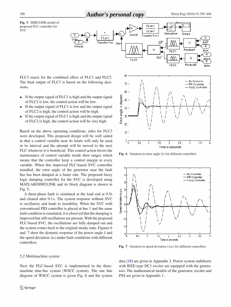
Fig. 5 SIMULINK model ofproposed FLC controller forSVC
FLC3 reacts for the combined effect of FLC1 and FLC2.The final output of FLC3 is based on the following deci-sions.
• If the output signal of FLC1 is high and the output signalof FLC2 is low, the control action will be low.
• If the output signal of FLC1 is low and the output signalof FLC2 is high, the control action will be high.
• If the output signal of FLC1 is high and the output signalof FLC2 is high, the control action will be very high.
Based on the above operating conditions, rules for FLC3were developed. This proposed design will be well suitedin that a control variable near its limits will only be usedin its interval and the attempt will be moved to the nextFLC whenever it is beneficial. This control action favors themaintenance of control variable inside their ranges whichmeans that the controller keep a control margin in everyvariable. When this improved FLC-based SVC controllerinstalled, the rotor angle of the generator near the faultbus has been damped at a faster rate. The proposed fuzzylogic damping controller for the SVC is developed usingMATLAB/SIMULINK and its block diagram is shown inFig. 5.
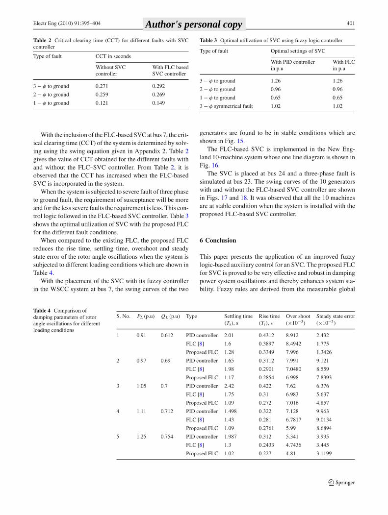
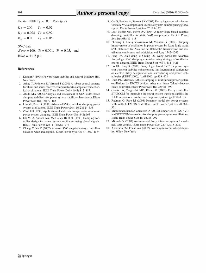
A three-phase fault is simulated at the load end at 0.5sand cleared after 0.1 s. The system response without SVCis oscillatory and leads to instability. When the SVC withconventional PID controller is placed at bus 1 and the samefault condition is simulated, it is observed that the damping isimproved but still oscillations are present. With the proposedFLC-based SVC, the oscillations are fully damped out andthe system comes back to the original steady state. Figures 6and 7 show the dynamic response of the power angle δ andthe speed deviation �ω under fault conditions with differentcontrollers.
5.2 Multimachine system
Next the FLC-based SVC is implemented in the three-machine nine-bus system (WSCC system). The one linediagram of WSCC system is given Fig. 8 and the system
Fig. 6 Variation in rotor angle (δ) for different controllers
Fig. 7 Variation in speed deviation (�ω) for different controllers
data [18] are given in Appendix 3. Power system stabilizerswith IEEE-type DC1 exciter are equipped with the genera-tors. The mathematical models of the generator, exciter andPSS are given in Appendix 1.
123
Author's personal copy

Electr Eng (2010) 91:395–404 399
Fig. 8 One line diagram ofWSCC system
Fig. 9 Damping of rotor angle oscillations for FLC–SVC for threephase fault at bus 7
Case 1 The FLC-based SVC is installed at bus 8 near gener-ator 2. With the initial power flow conditions, a three phaseto ground short circuit was simulated at 0.5 s and clearedat 0.6 s near bus 7. In Figs. 9, 10, 11, and 12 the variationof rotor angle δ, SVC voltage, speed deviation �ω, and thesusceptance Bsvc of SVC with PID controller, existing FLCand proposed FLC-based SVC controller are plotted. In thisstudy case, fault condition starting at 0.5 s, existing for theperiod of 0.1 s is shown in Fig. 9. It is clear that the rotorangle damping using fuzzy controller is more effective thanthe PID controller. The settling time of both controllers isfound to be the same, but the amplitude of rotor angle isreduced in the proposed FLC controller.
Fig. 10 Bus voltage in p.u with FLC for 3-phase fault at bus 7
From Fig. 10, it is observed that the bus voltage with theproposed FLC–SVC is controlled during fault conditions. IfPID controllers are employed, the bus voltage increases dur-ing the fault period, which causes additional voltage injectionin the system instead of current injection. This will be theremarkable advantage while using an FLC-based controller.It is also observed that when using the proposed FLC-basedSVC controller, the voltage rise is reduced during fault con-ditions and maintained at 1 p.u. at post-fault conditions.
From Fig. 11, it is identified that the angular speed devi-ations �ω will be same for the two controllers and in thepost-fault period, the angular speed deviations are quicklyreduced using the proposed FLC controller.
123
Author's personal copy

400 Electr Eng (2010) 91:395–404
Fig. 11 Angular speed deviation in p.u for 3-phase fault at bus 7
Fig. 12 Control of Bsvc with FLC based SVC for three phase fault atbus 7
From Fig. 12, the injection of BSVC during fault conditionis demonstrated. When the fault occurs, with the PID con-troller the susceptance injected will be at maximum of 1.1p.u. With control through the existing FLC it was reduced to0.9 p.u. and with the proposed FLC it is reduced to 0.6 p.u.It is also observed that the maximum susceptance includedin the system is only for a few seconds thus optimizing theutilization of the SVC. When compared to the PID controller,susceptance included in the circuit is reduced in the proposedFLC controller which improves the performance of the SVC.
Case 2 In this case, with the same location of SVC at bus8, power of load bus 7 is increased to 1.5 p.u at 0.75 s with0.5 s duration. The system response is studied with both PIDand the FLC-based SVC controller. For this overloaded con-dition also, SVC supplies reactive power during this periodand quickly maintains the system stability. From the Fig. 13,it can be seen that complete damping of rotor angle oscilla-
Fig. 13 Damping of rotor angle oscillations for FLC–SVC for loadingcondition of 1.5 p.u
Fig. 14 Control of Bsvc for loading condition of 1.5 p.u
tions occurs at 2.25 s only with the PID controller, whereasthe FLC controller damps out the oscillations at 1.5 s.
From Fig. 14, it can be observed that for the overloadconditions, with the PID controller, the susceptance Bsvcincluded in the system has increased from 0.25 p.u to 0.75p.u at 0.5 s at which the disturbance occurs. With the exist-ing FLC controller and the proposed FLC controller, themaximum susceptance included is also 0.75 p.u. After thetime interval of 0.5 s, the capacitive effect is changed over tomaximum inductive effect of −1 p.u with the proposed FLCcontroller which will lead to damping out the oscillations atreduced time interval. It is observed from the Figs. 12 and14, with the proposed FLC controller, the susceptance Bsvcto be injected at overloading conditions (1.5 p.u) is less thanthe susceptance injected during fault conditions.
123
Author's personal copy
Electr Eng (2010) 91:395–404 401
Table 2 Critical clearing time (CCT) for different faults with SVCcontroller
Type of fault CCT in seconds
Without SVC With FLC basedcontroller SVC controller
3 − φ to ground 0.271 0.292
2 − φ to ground 0.259 0.269
1 − φ to ground 0.121 0.149
With the inclusion of the FLC-based SVC at bus 7, the crit-ical clearing time (CCT) of the system is determined by solv-ing using the swing equation given in Appendix 2. Table 2gives the value of CCT obtained for the different faults withand without the FLC–SVC controller. From Table 2, it isobserved that the CCT has increased when the FLC-basedSVC is incorporated in the system.
When the system is subjected to severe fault of three phaseto ground fault, the requirement of susceptance will be moreand for the less severe faults the requirement is less. This con-trol logic followed in the FLC-based SVC controller. Table 3shows the optimal utilization of SVC with the proposed FLCfor the different fault conditions.
When compared to the existing FLC, the proposed FLCreduces the rise time, settling time, overshoot and steadystate error of the rotor angle oscillations when the system issubjected to different loading conditions which are shown inTable 4.
With the placement of the SVC with its fuzzy controllerin the WSCC system at bus 7, the swing curves of the two
Table 3 Optimal utilization of SVC using fuzzy logic controller
Type of fault Optimal settings of SVC
With PID controller With FLCin p.u in p.u
3 − φ to ground 1.26 1.26
2 − φ to ground 0.96 0.96
1 − φ to ground 0.65 0.65
3 − φ symmetrical fault 1.02 1.02
generators are found to be in stable conditions which areshown in Fig. 15.
The FLC-based SVC is implemented in the New Eng-land 10-machine system whose one line diagram is shown inFig. 16.
The SVC is placed at bus 24 and a three-phase fault issimulated at bus 23. The swing curves of the 10 generatorswith and without the FLC-based SVC controller are shownin Figs. 17 and 18. It was observed that all the 10 machinesare at stable condition when the system is installed with theproposed FLC-based SVC controller.
6 Conclusion
This paper presents the application of an improved fuzzylogic-based auxiliary control for an SVC. The proposed FLCfor SVC is proved to be very effective and robust in dampingpower system oscillations and thereby enhances system sta-bility. Fuzzy rules are derived from the measurable global
Table 4 Comparison ofdamping parameters of rotorangle oscillations for differentloading conditions
S. No. PL (p.u) QL (p.u) Type Settling time Rise time Over shoot Steady state error(Ts), s (Tr), s (×10−3) (×10−5)
1 0.91 0.612 PID controller 2.01 0.4312 8.912 2.432
FLC [8] 1.6 0.3897 8.4942 1.775
Proposed FLC 1.28 0.3349 7.996 1.3426
2 0.97 0.69 PID controller 1.65 0.3112 7.991 9.121
FLC [8] 1.98 0.2901 7.0480 8.559
Proposed FLC 1.17 0.2854 6.998 7.8393
3 1.05 0.7 PID controller 2.42 0.422 7.62 6.376
FLC [8] 1.75 0.31 6.983 5.637
Proposed FLC 1.09 0.272 7.016 4.857
4 1.11 0.712 PID controller 1.498 0.322 7.128 9.963
FLC [8] 1.43 0.281 6.7817 9.0134
Proposed FLC 1.09 0.2761 5.99 8.6894
5 1.25 0.754 PID controller 1.987 0.312 5.341 3.995
FLC [8] 1.3 0.2433 4.7436 3.445
Proposed FLC 1.02 0.227 4.81 3.1199
123
Author's personal copy

402 Electr Eng (2010) 91:395–404
Fig. 15 Swing curves of two generators with FLC based SVCcontroller
Fig. 16 One line diagram of New England 10 machine system
Fig. 17 Swing curves of generators without controller
signals like line active power flow, and remote generatorspeed deviation. The performance of the proposed FLC–SVCcontroller is then compared with the PID controller-based
Fig. 18 Swing curves of generators with proposed FLC–SVCcontroller
SVC and existing FLC using non-linear simulation results.Among these, the performance of the proposed controller isfound to be better and it damps out the system oscillationsat a faster rate. In the existing FLC controller using globalsignals, a single FLC controller with limited rules has beendeveloped. In this work, additional fuzzy controllers withadditional rules have been developed through which flexiblecontrol of BSVC can be done during disturbance conditions.The increase in output decision rules will lead to the optimalutilization of the SVC in system-overloading conditions. Itwas also observed that the performance of the proposed FLC–SVC controller was better than that of the existing FLC con-troller in both the SMIB system and the multimachine system.
Appendix 1: Modeling of power system components
A. Generator
The generator is represented by third order model compris-ing the electromechanical swing equation and the generatorinternal voltage equations [10] given by
δ = ω0ω (4)
ω = 1
M(Pm + G + Kdω − Pe) (5)
E ′q = 1
T ′do
[Efd − (xd − x ′d)id − E ′
q] (6)
where
δ = Rotor angle in degreesω = angular speed in rad/sPm = Mechanical power developed by the generatorKd = Damping constant of the generatorPe = Electrical Power delivered in p.u
123
Author's personal copy

Electr Eng (2010) 91:395–404 403
B
C
sT
sT
1
1
4
3
2
1
1
1
1
1
1 sT
sT
sT
sT
sT
sTK
w
w
upss
Vref
Vmeas
max
RV
minRV
min
pssU
max
pssU
Efd+-
+ A
A
sT
K
1
Regulator
Power system stabilizer
Verr
Fig. 19 IEEE type DC1 exciter with power system stabilizer
Xd, Xq = Direct and quadrature axis reactance of the gen-erator in p.uEd, Eq = Direct and quadrature axis voltages behind thetransient reactance in p.u
B. Exciter and PSS
The block diagram representing IEEE type 1 DC exciter andPSS accommodated with the generator is shown in Fig. 19which is modeled with the following equations
Efd = K A
TA(Vref − Vt + UPSS) − Efd
TA(7)
Pe = vdid + vqiq (8)
and
Vt = (v2d + v2
q)1/2 (9)
with vd = E sin δ − (xqiq)Ds, vq = E ′q − x ′
did and
G =(
KG1 + KG2
1 + sTG
)
(10)
UPSS = − 1
K P
(sT1
1 + sT2
) (1 + sT3
1 + sT4
)
δ (11)
where
K A and TA = gain and time constants of the exciterVref = reference voltage in p.uVt = Terminal voltage in p.uEfd = Field voltage of the generator in p.uKG1, KG2 = Gain constants of the GovernorK P = Gain of the PSST1, T2, T3 and T4 = Time constants of the PSSDs = Damping coefficient of PSSUPSS = Output of PSS in p.u
Appendix 2: Swing equation of multimachine systems
In the multimachine system model, the loads are assumed tobe constant impedance and converted into admittances as
yLi = −(PLi − j QLi )
V 2i
(12)
where i − 1, . . .m.The network equations for the new augmented network
can be written as[
IA
0
]
=(
YA YB
YC YD
)[E A
VB
]
(13)
which can be reduced to
IA =(
YA − YB YBY −1D YC
)E A = Yint E A (14)
where the elements of the IA and E A are
Ii = (Idi + j Iqi )ej (δi −π/2) (15)
Ei = Ei � δi (16)
The elements of Yinti are
Y i ji = Gi j + j Bi ji (17)
For the simulation of the multimachine system, first theadmittance matrix (Y) of the system is calculated and thecomplexity of transient stability analysis is reduced by con-sidering all the rotor angles of synchronous machines coin-cides with angle of the voltage behind the transient reactanceand all the machines are assumed to swing at coherent. Thepower flow equation of i th machine is calculated by
Pei =m∑
j=1
∣∣E ′
i
∣∣∣∣E ′
j
∣∣∣∣Yi j
∣∣ cos(θi j − δi + δ j ) (18)
And the swing equation is
Hi
π f0
d2δi
dt2 = Pmi −m∑
j=1
∣∣E ′
i
∣∣∣∣E ′
j
∣∣∣∣Yi j
∣∣ cos(θi j − δi + δ j )
(19)
Appendix 3: System data
Synchronous machine data
Xd = 1.8 X ′d = 0.3 X ′′
d = 0.15Xq = 1.8 X ′
d = 0.0 X ′′d = 0.15
T ′do = 6.0 T ′′
do = 0.04 H = 4T ′
qo = 0.2 T ′′do = 0.0
R = 0.002 X1 = 0.0
123
Author's personal copy
404 Electr Eng (2010) 91:395–404
Exciter IEEE Type DC 1 Data (p.u)
K A = 200 TA = 0.02
KF = 0.028 TF = 0.92
KE = 0.0 TE = 0.05
SVC dataKSVC = 100, T1 = 0.001, T2 = 0.05, and
Bsvc = ±1.5 p.u
References
1. Kundur P (1994) Power system stability and control. McGraw Hill,New York
2. Athay T, Podmore R, Virmani S (2001) A robust control strategyfor shunt and series reactive compensators to damp electromechan-ical oscillations. IEEE Trans Power Deliv 16(4):812–817
3. Abido MA (2005) Analysis and assessment of STATCOM baseddamping stabilizers for power system stability enhancement. ElectrPower Syst Res 73:177–185
4. Lerch E, Povh D (1991) Advanced SVC control for damping powersystem oscillations. IEEE Trans Power Syst 16(2):524–535
5. Zhou EH (1993) Application of static var compensator to increasepower system damping. IEEE Trans Power Syst 8(2):665
6. Ela MEA, Sallam AA, Mc Calley JD et al (1993) Damping con-troller design for power system oscillation using global signals.IEEE Trans Power syst 11(2):767–773
7. Chang Y, Xu Z (2007) A novel SVC supplementary controllersbased on wide area signals. Electr Power Syst Res 77:1569–1574
8. Gu Q, Pandey A, Starrett SK (2003) Fuzzy logic control schemesfor static VAR compensator to control system damping using globalsignal. Electr Power Syst Res 67:115–122
9. Lu J, Nehrir MH, Pierre DA (2004) A fuzzy logic-based adaptivedamping controller for static VAR compensator. Electric PowerSyst Res 68:113–118
10. Phorang K, Leelajindakraireak M, Mizutani Y (2002) Dampingimprovement of oscillation in power system by fuzzy logic basedSVC stabilizer. In: Asia Pacific. IEEE/PES transmission and dis-tribution conference and exhibition, vol 3, pp 1542–1547
11. Fang DZ, Xiao dong Y, Chung TS, Wong KP (2004) Adaptivefuzzy-logic SVC damping controller using strategy of oscillationenergy descent. IEEE Trans Power Syst 9(3):1414–1421
12. Lo KL, Laiq K (2000) Fuzzy logic based SVC for power sys-tem transient stability enhancement. In: International conferenceon electric utility deregulation and restructuring and power tech-nologies (DRPT 2000), April 2000, pp 453–458
13. Dash PK, Mishra S (2003) Damping of multimodal power systemoscillations by FACTS devices using non linear Takagi–Sugenofuzzy controller. Electr Power Syst Res 25:481–490
14. Ghafori A, Zolghadri MR, Ehsan M (2001) Fuzzy controlledSTATCOM for improving the power system transient stability. In:IEEE international conference on power system, pp 1178–1185
15. Radman G, Raje RS (2008) Dynamic model for power systemswith multiple FACTS controllers. Electr Power Syst Res 78:361–371
16. Midhulananthan N, Canizares CA (2003) Comparison of PSS, SVCand STATCOM controllers for damping power system oscillations.IEEE Trans Power Syst 18(2):786–792
17. Miranda V (2007) An improved fuzzy inference system for volt-age/VAR control. IEEE Trans Power Syst 22(4):2013–2020
18. Anderson PM, Fouad AA (2002) Power system control and stabil-ity. Wiley, New York
123
Author's personal copy