Multi Air Conditioner SVC MANUAL(Exploded View) - Amazon ...
7
Multi Air Conditioner SVC MANUAL(Exploded View) MODEL : A8UW54GFA0 [LMU540HV] CAUTION Before Servicing the unit, read the safety precautions in General SVC manual. Only for authorized service personnel. Internal Use Only http://biz.lgservice.com
-
Upload
khangminh22 -
Category
Documents
-
view
2 -
download
0
Transcript of Multi Air Conditioner SVC MANUAL(Exploded View) - Amazon ...

Multi Air ConditionerSVC MANUAL(Exploded View)MODEL : A8UW54GFA0 [LMU540HV]
CAUTIONBefore Servicing the unit, read the safety precautions in General SVC manual.Only for authorized service personnel.
Internal Use Only
http://biz.lgservice.com

- 2 -Copyright ©2012 LG Electronics. Inc. All right reserved.Only for training and service purposes LGE Internal Use Only
1. Specification
Note:1. All data are based on the following conditions:
- Cooling Temperature : Indoor 27°C(80.6°F) DB / 19°C(66.2°F) WBOutdoor 35°C(95°F) DB / 24°C(75.2°F) WB
- Heating Temperature : Indoor 20°C(68°F) DB / 15°C(59°F) WBOutdoor 7°C(44.6°F) DB / 6°C(42.8°F) WB
- Piping Length : Interconnected Pipe Length = 5m- Difference Limit of Elevation (Outdoor ~ Indoor Unit) is Zero.
2. Wiring cable size must comply with the applicable local and nationalcode.
3. Due to our policy of innovation some specifications may be changedwithout notification.
4. Sound Level Values are measured at Anechoic chamber. Therefore, these values can be increased(maximum 3dB(A)) owing toambient conditions during opration.
Model NameA8UW54GFA0[LMU540HV]
Capacity Nominal Btu/h Class 54,000
CapacityCooling Min.~Rated~Max. Btu/h 14,000 ~ 52,500 ~ 63,200Heating Min.~Rated~Max. Btu/h 15,467 ~ 58,000 ~ 64,000
Power InputCooling Min.~Rated~Max. kW 1.0 ~ 5.10 ~ 5.86Heating Min.~Rated~Max. kW 1.49 ~ 5.34 ~ 6.19
EER / COP kBbu/h.W 10.3 / 3.2
SEER / SCOPNon Ducted 18.4 / 8.7
Mixed 17.1 / 8.7Ducted 15.8 / 8.7
Power Supply V , Ø , Hz 208/230, 1, 60
Running CurrentCooling Min.~Rated~Max. A 4.6 ~ 23.7 ~ 27.2Heating Min.~Rated~Max. A 6.9 ~ 24.8 ~ 28.7
Starting CurrentCooling Max. A -Heating Max. A -
Wiring ConnectionsPower Supply Cable (included Earth) No. x AWG 3C x 4.0Power and Communication Cable(included Earth)
Outdoor ~ BD unit No. x AWG 4C x 18
CombinationSum of Indoor Units Capacity kBtu/h 73Number of Indoor Units EA 8Number of BD Units EA 2
Casing Color - Warm Gray
DimensionsW x H x D mm 950 × 1380 × 330W x H x D inch 37.4 x 54.3 x 13.0
Net Weight kg (lbs) 97(213.8)
Compressor
Type - Twin RotaryModel Model x No. GPT442MAA x 1Motor type - BLDCMotor Output W x No. 4,000 (at 60Hz) x 1
Refrigerant
Type - R410APrecharged Amount g (oz) 4,400 (155.2)Chargeless-Pipe Length m (ft) 40 (131.2)Additional Charging Volume g/m (oz/ft) 20 (0.22)Control - Electronic Expansion Valve
Refrigerant OilType - FVC68DCharged volume cc x No. 1,300 x 1
Heat Exchanger (Row x Column x Fins per inch) x No. - (2 x 32 x 14) x2
FanType - PropellerAir Flow Rate m3/min(ft3/min) x No. 60 x 2
Fan MotorType - BLDCOutput W x No. 124.2 x 2
Sound Pressure LevelCooling Rated dB(A) 53Heating Rated dB(A) 54
Sound Power Level Cooling Rated dB(A) 69
Piping ConnectionsLiquid Outer Dia. mm(inch) x No. Ø 9.52 (3/8)Gas Outer Dia. mm(inch) x No. Ø 19.05 (3/4)
Piping Length
Total Piping Max. m (ft) 145 (475.7)Main Piping Max. m (ft) 55 (180.4)Total Branch Piping Max. m (ft) 90 (295.3)Each Branch Piping Max. m (ft) 15 (49.2)
Maximum HeightDifference
Outdoor Unit ~ Indoor Unit Max. m (ft) 30 (98.4)Indoor Unit ~ Indoor Unit Max. m (ft) 15 (49.2)
Operation Range(Outdoor Temperature)
Cooling Min. ~ Max. ℃ DB (℉ DB) -10 (14.0) ~ 48 (118.4)Heating Min. ~ Max. ℃ WB (℉ WB) -18 (-0.4) ~ 18 (64.4)
- 3 -Copyright ©2012 LG Electronics. Inc. All right reserved.Only for training and service purposes LGE Internal Use Only
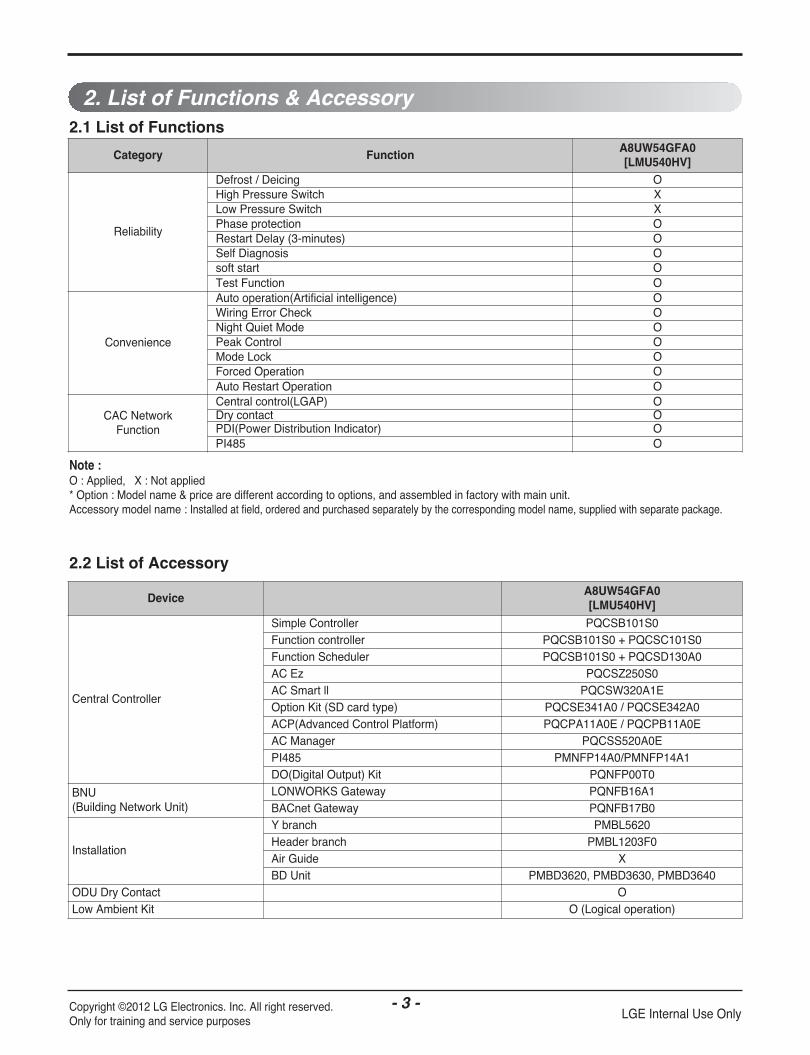
2. List of Functions & Accessory
Note :O : Applied, X : Not applied* Option : Model name & price are different according to options, and assembled in factory with main unit.Accessory model name : Installed at field, ordered and purchased separately by the corresponding model name, supplied with separate package.
2.2 List of Accessory
2.1 List of Functions
Category FunctionA8UW54GFA0[LMU540HV]
Reliability
Defrost / Deicing OHigh Pressure Switch XLow Pressure Switch XPhase protection ORestart Delay (3-minutes) OSelf Diagnosis Osoft start OTest Function O
Convenience
Auto operation(Artificial intelligence) OWiring Error Check ONight Quiet Mode OPeak Control OMode Lock OForced Operation OAuto Restart Operation O
CAC NetworkFunction
Central control(LGAP) ODry contact OPDI(Power Distribution Indicator) OPI485 O
DeviceA8UW54GFA0[LMU540HV]
Central Controller
Simple Controller PQCSB101S0Function controller PQCSB101S0 + PQCSC101S0Function Scheduler PQCSB101S0 + PQCSD130A0AC Ez PQCSZ250S0AC Smart ll PQCSW320A1EOption Kit (SD card type) PQCSE341A0 / PQCSE342A0ACP(Advanced Control Platform) PQCPA11A0E / PQCPB11A0EAC Manager PQCSS520A0EPI485 PMNFP14A0/PMNFP14A1DO(Digital Output) Kit PQNFP00T0
BNU(Building Network Unit)
LONWORKS Gateway PQNFB16A1BACnet Gateway PQNFB17B0
Installation
Y branch PMBL5620Header branch PMBL1203F0Air Guide XBD Unit PMBD3620, PMBD3630, PMBD3640
ODU Dry Contact OLow Ambient Kit O (Logical operation)

- 4 -Copyright ©2012 LG Electronics. Inc. All right reserved.Only for training and service purposes LGE Internal Use Only
3. Piping Diagrams
: Cooling: Heating
M
PressureSensor
4 wayValve
DischargeTemperatureThermistor
SuctionTemperatureThermistor
FusiblePlug
Accumulator
HotgasValve
InverterCompressor
Strainer Strainer
Condenser OutTemperatureThermistor
Inlet AirTemperatureThermistor
Outdoor Unit
Ø9.52Flare Connection
Ø19.05Flare Connection
Electronic Expansion Valve
Condenser MidTemperatureThermistor
PCB Connector Description
CN-TH1 Air / Cond Out
CN-TH2 Suction / Discharge
CN-TH3 Cond Mid
CN-P/SENSOR(H) Pressure Sensor
CN-EEV-MAIN Electronic Expansion Valve
CN-HOTGAS Hotgas Valve

- 5 -Copyright ©2012 LG Electronics. Inc. All right reserved.Only for training and service purposes LGE Internal Use Only
MAIN PCB INVERTER PCB
CN_4WAY
CN_POWER
WCN_P(N)
WCN_P(L)
CN-485/DRY
CN_COMM
CN_FLASHCN_WRITER
CN_TH3CN-P/SENSOR (H)
CN_TH2
CN_TH1CN_CENTRALCN_JIG_PC
CN-COM
CN_EEV_MAIN
CN-HOTGAS
CN(N)
CN(L)
CN-MOTOR1
CN-MOTOR2 CN-MAIN
CN_POWER
4. Wiring Diagrams
- 6 -Copyright ©2012 LG Electronics. Inc. All right reserved.Only for training and service purposes LGE Internal Use Only
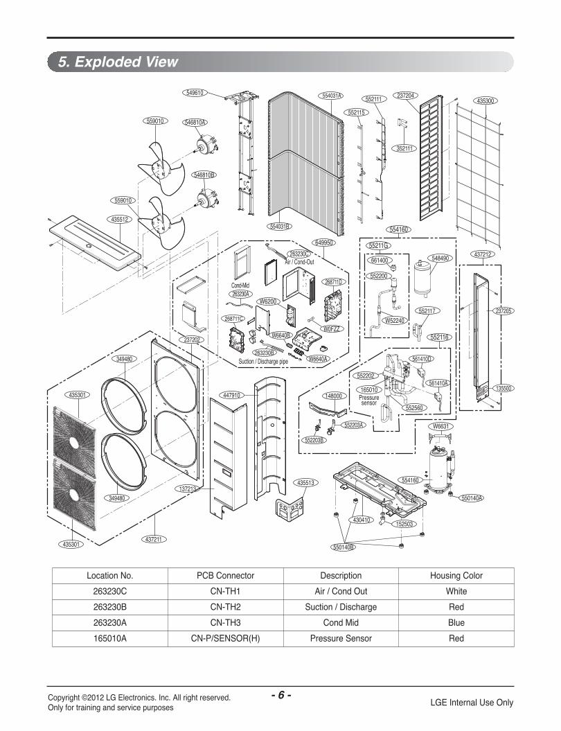
5. Exploded View
435512
552115
435301
137213
447910
559010
549610 237204
661400
349480
435301437211
435513
349480
554031B
554031A
352111
546810A
546810B
552117
559010
W52240
552200
55211G
554160
552116
550140A
435300552111
437212
237205
135500
548490
554160
W6631
148000
552203B
552203A
649950
W6200
268711D
263230CAir / Cond-Out
Suction / Discharge pipe263230B
268711C
263230ACond-Mid
W6640B
W6640A
W0FZZ
237202
165010Pressuresensor
552202
561410D
552560
561410A
152503
550140B
430410
Location No. PCB Connector Description Housing Color
263230C CN-TH1 Air / Cond Out White
263230B CN-TH2 Suction / Discharge Red
263230A CN-TH3 Cond Mid Blue
165010A CN-P/SENSOR(H) Pressure Sensor Red

P/NO : MFL67452409 JULY, 2012