LG Air Conditioner SVC MANUAL(EXPLODED VIEW)
15
LG Air Conditioner SVC MANUAL(EXPLODED VIEW) MODEL : LVN180HV4 LVN181HV4 LVN240HV4 LVN241HV4 LVN360HV4 LVN361HV4 LVN420HV LVN480HV CAUTION Before Servicing the unit, read the safety precautions in General SVC manual. Only for authorized service personnel. CONFIDENTIAL Any reproduction, duplication, distribution (including by way of email, facsimile or other electronic means), publication, modification, copying or transmission of this Service Manual is STRICTLY PROHIBITED unless you have obtained the prior written consent of the LG Electronics entity from which you received this Service Manual. The material covered by this prohibition includes, without limitation, any text, graphics or logos in this Service Manual. Copyright © 2016 - 2020 LG Electronics Inc. All rights reserved. Only training and service purposes.
-
Upload
khangminh22 -
Category
Documents
-
view
0 -
download
0
Transcript of LG Air Conditioner SVC MANUAL(EXPLODED VIEW)

LG Air ConditionerSVC MANUAL(EXPLODED VIEW)
MODEL : LVN180HV4 LVN181HV4 LVN240HV4 LVN241HV4 LVN360HV4 LVN361HV4 LVN420HV LVN480HV
CAUTIONBefore Servicing the unit, read the safety precautions in General SVC manual.Only for authorized service personnel.
CONFIDENTIAL
Any reproduction, duplication, distribution (including by way of email, facsimile or other electronic means), publication, modification, copying or transmission of this Service Manual is STRICTLY PROHIBITED unless you have obtained the prior written consent of the LG Electronics entity from which you received this Service Manual. The material covered by this prohibition includes, without limitation, any text, graphics or logos in this Service Manual.
Copyright © 2016 - 2020 LG Electronics Inc. All rights reserved. Only training and service purposes.

Specifications
1. Specifications
- 2 - Copyright © 2016 - 2020 LG Electronics Inc. All rights reserved. Only training and service purposes.
n Indoor Units
Note :1. All data are based on the following conditions :
- Cooling temperature : Indoor 26.7 ℃ (80 ℉) DB / 19.4 ℃ (67 ℉) WBOutdoor 35 ℃ (95 ℉) DB / 23.9 ℃ (75 ℉) WB
- Piping length : Interconnected pipe length = 7.5m (24.6 ft)- Difference limit of elevation (outdoor unit ~ indoor unit) is zero.
2. Wiring cable size must comply with the applicable local and national code.3. Due to our policy of innovation some specifications may be changed without notification.4. Sound level values are measured at anechoic chamber.
Therefore, these values can be increased owing to ambient conditions during operation.
Model Name LVN180HV4 LVN181HV4 LVN240HV4 LVN241HV4
Power Supply V , Ø , Hz 208 / 230, 1, 60 208 / 230, 1, 60 208 / 230, 1, 60 208 / 230, 1, 60
Dimensions BodyW x H x D mm 457 x 1236 x 540 457 x 1236 x 540 457 x 1236 x 540 457 x 1236 x 540
W x H x D inch 18 x 48-11/16 x 21-1/4 18 x 48-11/16 x 21-1/4 18 x 48-11/16 x 21-1/4 18 x 48-11/16 x 21-1/4
Net Weight Body kg (lbs) 55.5 (122.3) 53 (116.8) 55.5 (122.3) 53 (116.8)
HeatExchanger
(Row x Column x FPDM) - (3x24x18) x 2 (2x24x18) x 2 (3x24x18) x 2 (2x24x18) x 2
Face Area m2 (ft2) 0.22 (2.37) x 2 0.22 (2.37) x 2 0.22 (2.37) x 2 0.22 (2.37) x 2
Fan
Type - Sirocco Fan Sirocco Fan Sirocco Fan Sirocco Fan
Air Flow RateH / M / L m3/min 18 / 16.5 / 13.5 18 / 16.5 / 13.5 20 / 18 / 13.5 20 / 18 / 13.5
H / M / L ft3/min 640 / 580 / 480 640 / 580 / 480 710 / 640 / 480 710 / 640 / 480
FanMotor
Type - BLDC ECM BLDC ECM
Output W x No. 198 250 198 250
Dehumidification Rate ℓ/h (pts/h) 2 (4.2) 2 (4.2) 2.5 (5.3) 2.5 (5.3)
Sound Pressure Level H / M / L dB(A) 42 / 42 / 41 35 / 33 / 30 43 / 42 / 41 36 / 34 / 30
Sound Power Level Max. dB(A) - - - -
PipingConnections
Liquid mm(inch) Ø 9.52 (3/8) Ø 9.52 (3/8) Ø 9.52 (3/8) Ø 9.52 (3/8)
Gas mm(inch) Ø 15.88 (5/8) Ø 15.88 (5/8) Ø 15.88 (5/8) Ø 15.88 (5/8)
Drain_Secondary &Primary(ID.)
mm(inch) 19.05 (3/4 FPT) 19.05 (3/4 FPT) 19.05 (3/4 FPT) 19.05 (3/4 FPT)
Safety Devices - Fuse Fuse Fuse Fuse
Power and Communication Cable(included Earth)
No. x mm2
(AWG)4C X 0.75 (18) 4C X 0.75 (18) 4C X 0.75 (18) 4C X 0.75 (18)
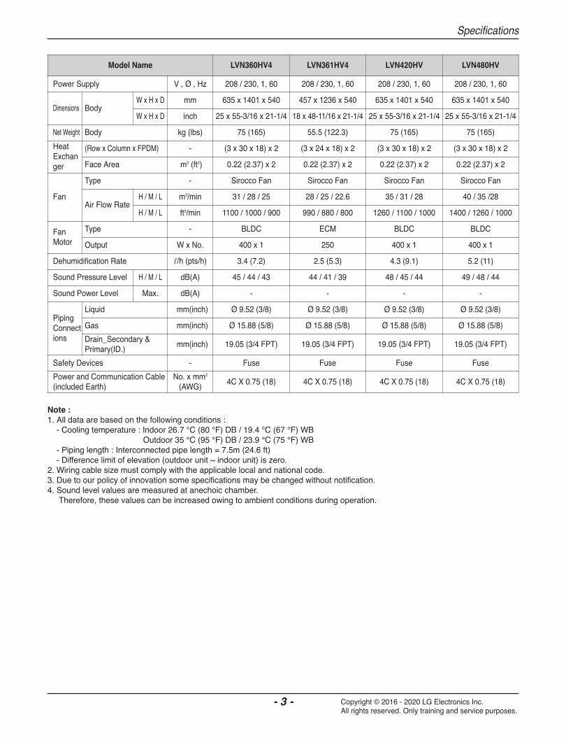
Specifications
- 3 - Copyright © 2016 - 2020 LG Electronics Inc. All rights reserved. Only training and service purposes.
Note :1. All data are based on the following conditions :
- Cooling temperature : Indoor 26.7 ℃ (80 ℉) DB / 19.4 ℃ (67 ℉) WBOutdoor 35 ℃ (95 ℉) DB / 23.9 ℃ (75 ℉) WB
- Piping length : Interconnected pipe length = 7.5m (24.6 ft)- Difference limit of elevation (outdoor unit ~ indoor unit) is zero.
2. Wiring cable size must comply with the applicable local and national code.3. Due to our policy of innovation some specifications may be changed without notification.4. Sound level values are measured at anechoic chamber.
Therefore, these values can be increased owing to ambient conditions during operation.
Model Name LVN360HV4 LVN361HV4 LVN420HV LVN480HV
Power Supply V , Ø , Hz 208 / 230, 1, 60 208 / 230, 1, 60 208 / 230, 1, 60 208 / 230, 1, 60
Dimensions BodyW x H x D mm 635 x 1401 x 540 457 x 1236 x 540 635 x 1401 x 540 635 x 1401 x 540
W x H x D inch 25 x 55-3/16 x 21-1/4 18 x 48-11/16 x 21-1/4 25 x 55-3/16 x 21-1/4 25 x 55-3/16 x 21-1/4
Net Weight Body kg (lbs) 75 (165) 55.5 (122.3) 75 (165) 75 (165)
HeatExchanger
(Row x Column x FPDM) - (3 x 30 x 18) x 2 (3 x 24 x 18) x 2 (3 x 30 x 18) x 2 (3 x 30 x 18) x 2
Face Area m2 (ft2) 0.22 (2.37) x 2 0.22 (2.37) x 2 0.22 (2.37) x 2 0.22 (2.37) x 2
Fan
Type - Sirocco Fan Sirocco Fan Sirocco Fan Sirocco Fan
Air Flow RateH / M / L m3/min 31 / 28 / 25 28 / 25 / 22.6 35 / 31 / 28 40 / 35 /28
H / M / L ft3/min 1100 / 1000 / 900 990 / 880 / 800 1260 / 1100 / 1000 1400 / 1260 / 1000
FanMotor
Type - BLDC ECM BLDC BLDC
Output W x No. 400 x 1 250 400 x 1 400 x 1
Dehumidification Rate ℓ/h (pts/h) 3.4 (7.2) 2.5 (5.3) 4.3 (9.1) 5.2 (11)
Sound Pressure Level H / M / L dB(A) 45 / 44 / 43 44 / 41 / 39 48 / 45 / 44 49 / 48 / 44
Sound Power Level Max. dB(A) - - - -
PipingConnections
Liquid mm(inch) Ø 9.52 (3/8) Ø 9.52 (3/8) Ø 9.52 (3/8) Ø 9.52 (3/8)
Gas mm(inch) Ø 15.88 (5/8) Ø 15.88 (5/8) Ø 15.88 (5/8) Ø 15.88 (5/8)
Drain_Secondary &Primary(ID.)
mm(inch) 19.05 (3/4 FPT) 19.05 (3/4 FPT) 19.05 (3/4 FPT) 19.05 (3/4 FPT)
Safety Devices - Fuse Fuse Fuse Fuse
Power and Communication Cable(included Earth)
No. x mm2
(AWG)4C X 0.75 (18) 4C X 0.75 (18) 4C X 0.75 (18) 4C X 0.75 (18)

Function Table
- 4 - Copyright © 2016 - 2020 LG Electronics Inc. All rights reserved. Only training and service purposes.
2. Function Tablen Indoor Units
Notes :O : Applied, X : Not appliedAccessory model name : Installed at field, ordered and purchased separately by the corresponding model name, supplied with separate package.
Category FunctionsLVN180HV4 / LVN240HV4 /LVN360HV4 / LVN420HV /
LVN480HV4
LVN181HV4 / LVN241HV4 /LVN361HV4
Air flow
Air supply outlet 1 1Airflow direction control (left & right) X XAirflow direction control (up & down) X XAuto swing (left & right) X XAuto swing (up & down) X XAirflow steps (fan/cool/heat) 3 / 3 / 3 3 / 3 / 3Chaos wind(auto wind) X XJet cool/heat X XSwirl wind X X
Air purifying
Triple filter (Deodorizing) X XPlasma air purifier X XAllergy Safe filter X XLong-life prefilter (washable) X X
Installation
Drain pump X XE.S.P. control O XElectric heater ANEH***B* ANEH***B*Aux heater Relay Kit X PRARH0High ceiling operation X XAuto Elevation Grille X X
ReliabilityHot start O OSelf diagnosis O OSoft dry operation O O
Convenience
Auto changeover O OAuto cleaning X XAuto operation(artificial intelligence) X XAuto Restart O OChild lock O OForced operation X XGroup control O OSleep mode O OTimer(on/off) O OTimer(weekly) O OTwo thermistor control O O
Individual control
Standard Wired remote controller PREMTB10U PREMTB10UDeluxe wired remote controller X XSimple wired remote controller PQRCH/V**** PQRCH/V****Simple Wired remote controller(for hotel use) X XWireless remote controller* PQWRHQ0FDB PQWRHQ0FDB
Network function
General central controller (Non LGAP) X XNetwork Solution(LGAP) O O ODry contact O OPI 485(for Indoor Unit) X X
Special function kitZone controller X XCTI(Communication transfer interface) X XElectronic thermostat X X
OthersRemote temperature sensor PQRSTA0 PQRSTA0Group control wire PZCWRCG3 PZCWRCG3Telecom shelter controller X X

Piping Diagrams
- 5 - Copyright © 2016 - 2020 LG Electronics Inc. All rights reserved. Only training and service purposes.
3. Piping Diagrams
Gas pipe connection port(flare connection)
Liquid pipe connection port(flare connection)
: Cooling
: Heating
Thermistor for
Evaporator Inlet Temperature
Thermistor for
Indoor Air Temperature
Thermistor for EvaporatorOutlet Temperature
Heat Exchanger
Sirocco Fan
M
Notes : Description is expressed based on Cooling mode.
Description PCB Connector
Thermistor for Indoor Air Temperature CN_ROOM
Thermistor for Evaporator Inlet Temperature CN_PIPE_IN
Thermistor for Evaporator Outlet Temperature CN_PIPE_OUT

- 6 -
Wiring Diagram
Copyright © 2016 - 2020 LG Electronics Inc. All rights reserved. Only training and service purposes.
4. Wiring Diagram
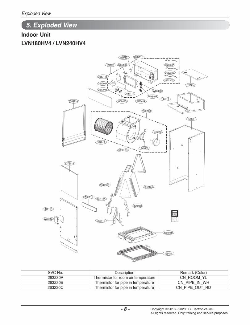
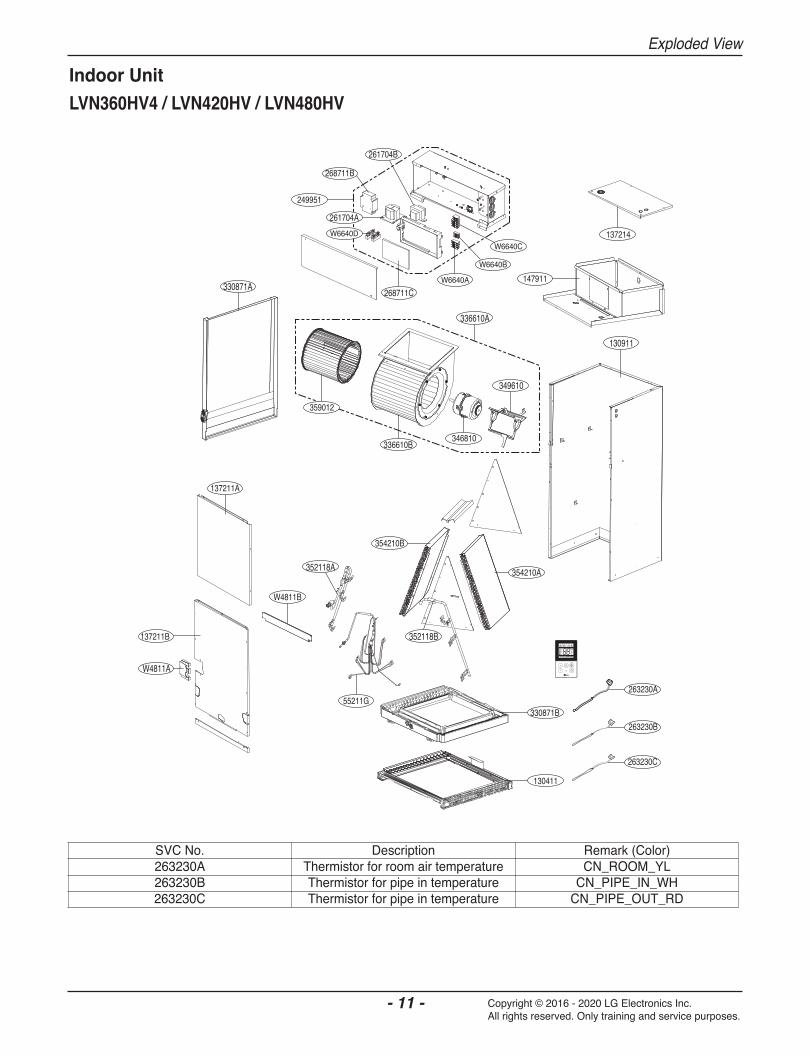
n Indoor Unit

Wiring Diagram
- 7 - Copyright © 2016 - 2020 LG Electronics Inc. All rights reserved. Only training and service purposes.
n Main PCBLVN180HV4 / LVN181HV4 / LVN240HV4 / LVN241HV4
CN_OUT_WH
CN_REMO_GR
CN_CC_WH
CN_EXT_BL
CN_PIPE_IN_WH
CN_ROOM_YL
CN_PIPE_OUT_RD
CN_DAMPER_GRCN_FLOAT_BL CN_MOTOR_WH
CN_AIRC_BL
CN_PTC_BLCN_OPTION_WH
CN_DAMPER_RD
CN_ZONE_WH
CN_POWER_WHCN_WF_BL
LVN360HV4 / LVN361HV4 / LVN420HV / LVN480HV
CN_CC_WH
CN_AIRC_BLCN_OPTION_WH
CN_DAMPER_GY
CN_ZONE_WH
CN_OUT_WH
CN_POWER_WHCN_WF_BL
CN_REMO_GR
CN_EXT_BL
CN_PIPE_IN_WH
CN_ROOM_YL
CN_PIPE_OUT_RD
CN_DAMPER_GRCN_FLOAT_BL CN_MOTOR_WH
CN_PTC_BL
W4811B
137211A
137214
330871A
W4811A
137211B
147911
330871B
130411
130911
346810
336610A
W6640C
249951
W6640AW6640D
268711AW6640B
268711B
359012
336610B 349600
261704A
261704B
W0FZZ 268711C
W6640D
354210B
352118A
352114
352118B
354210A
263230C
263230B
263230A

W4811B
137211A
137214
W4811A
137211B
147911
330871B
130411
130911
346810
336610A
249951
W6640A268711B
268711C
359012
336610B
261704A
261704B
W0FZZ 268711D
W6640D
349610
W6640C
W6640B
330871A
352114
352118A
352118B
354210B
354210A
263230A263230C
263230B

W4811B
137211A
137214
W4811A
137211B
147911
330871B
130411
130911
346810
336610A
W6640C
249951
W6640A
268711BW6640B
268711C
359012
336610B
261704A
261704B
W0FZZ268711D
W6640D
349610
330871A
263230A263230C
263230B
354210B
352118A
352114
352118B
354210A
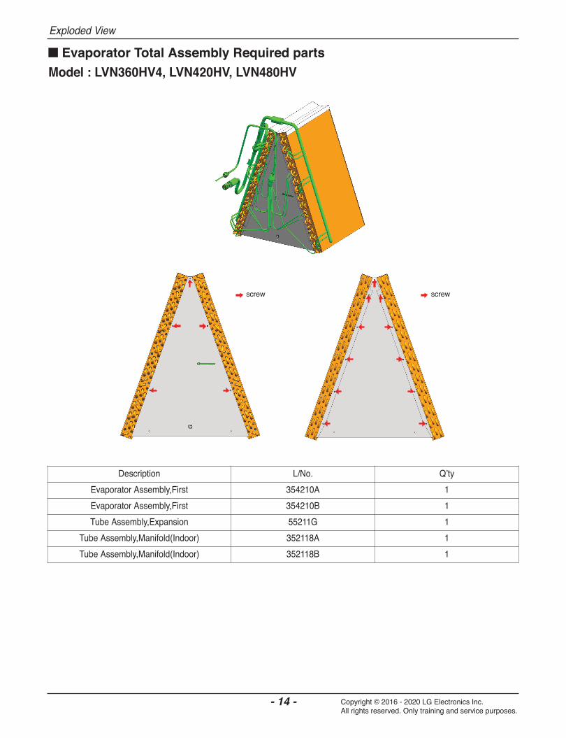
352118B
352118A
55211G
354210B
W4811B
137211A
137214
330871A
W4811A
137211B
249951
147911
330871B
130411
130911
349610
336610A
263230A
263230B
263230C
W6640C
268711B
268711CW6640A
W6640B
261704B
261704A
359012
336610B346810
354210A
W6640D


P/NO : MFL68082947
Copyright © 2016 - 2020 LG Electronics Inc. All rights reserved. Only training and service purposes.