A Design Office Approach to Supplemental Damping Using ...
10
Steel Innovations Conference 2013 Christchurch, New Zealand 21-22 February 2013 A DESIGN OFFICE APPROACH TO SUPPLEMENTAL DAMPING USING FLUID VISCOUS DAMPERS J.D. Pettinga 1 , S. Oliver 2 and T.E. Kelly 3 ABSTRACT The use of supplemental damping to control structural deformations and forces due to seismic ground motions has been demonstrated in overseas applications to be a very effective means of improving building performance. The combination of structural steel frames with energy dissipation provided by Fluid Viscous Dampers (FVD) is a surprisingly cost efficient means to achieving Low Damage Design (LDD) that is effective at both serviceability and ultimate limit states. Although there is a substantial volume of literature on the response of buildings incorporating FVDs, there are few references that provide simple access for designers to initiate a building design using viscous damping. This paper outlines the conceptual steps to preliminary and developed design of a viscous damped steel moment-frame and provides references that designers should look to for detailed guidance and understanding. The key features to verification and specification of viscous damped lateral force resisting systems are identified and demonstrated through with a simple design example. Introduction Modern seismic design is strongly founded on the concept of energy absorption through reliable ductile behaviour. The application of Capacity Design (Park and Paulay, 1975; Paulay and Priestley, 1992) and acceptance that a structure will sustain damage has been well demonstrated to achieve acceptable Life- Safety performance for a range of lateral force-resisting systems. Typically in New Zealand, structural steel systems fall into the categories of ductile Moment-Resisting Frames (MRF), and braced frames of varying forms and ductile capability. In particular Eccentric Braced Frames (EBF) and Buckling Restrained Braced Frames (BRBF) provide large amounts of hysteretic energy absorption, and accordingly have been referred to as high performance systems, in the context of energy dissipation. The incorporation of supplemental damping devices in the form of hysteretic or viscous/visco-elastic dampers provide designers with the opportunity to move damage away from the primary structural elements. Design and analysis guidance is available from a range of sources (Constantinou et al, 1998; Hanson and Soong, 2001; Christopoulos and Filiatrault, 2006; Symans et al., 2008) however they have not necessarily provided focus on the initial steps of choosing a performance target. With supplemental damping the energy absorption effects are concentrated in specific components that are activated by differential movement between adjacent structural elements. In the case of hysteretic dampers, the activation is displacement dependent, while viscous dampers are velocity dependent. This important distinction will be clarified in subsequent sections, however a review of the equation of motion (Eq. 1) in a basic form indicates the separation of components. 1 Project Engineer, Holmes Consulting Group LP, Christchurch, P.O. Box 6718 2 Technical Director, Holmes Consulting Group LP, Christchurch, P.O. Box 6718 3 Technical Director, Holmes Consulting Group LP, Hamilton, P.O. Box 4283
-
Upload
khangminh22 -
Category
Documents
-
view
5 -
download
0
Transcript of A Design Office Approach to Supplemental Damping Using ...

Steel Innovations Conference 2013
Christchurch, New Zealand
21-22 February 2013
A DESIGN OFFICE APPROACH TO SUPPLEMENTAL DAMPING USING FLUID VISCOUS DAMPERS
J.D. Pettinga1, S. Oliver
2 and T.E. Kelly
3
ABSTRACT
The use of supplemental damping to control structural deformations and forces due to seismic ground
motions has been demonstrated in overseas applications to be a very effective means of improving building
performance. The combination of structural steel frames with energy dissipation provided by Fluid Viscous
Dampers (FVD) is a surprisingly cost efficient means to achieving Low Damage Design (LDD) that is effective
at both serviceability and ultimate limit states. Although there is a substantial volume of literature on the
response of buildings incorporating FVDs, there are few references that provide simple access for designers
to initiate a building design using viscous damping.
This paper outlines the conceptual steps to preliminary and developed design of a viscous damped steel
moment-frame and provides references that designers should look to for detailed guidance and
understanding. The key features to verification and specification of viscous damped lateral force resisting
systems are identified and demonstrated through with a simple design example.
Introduction
Modern seismic design is strongly founded on the concept of energy absorption through reliable ductile
behaviour. The application of Capacity Design (Park and Paulay, 1975; Paulay and Priestley, 1992) and
acceptance that a structure will sustain damage has been well demonstrated to achieve acceptable Life-
Safety performance for a range of lateral force-resisting systems. Typically in New Zealand, structural steel
systems fall into the categories of ductile Moment-Resisting Frames (MRF), and braced frames of varying
forms and ductile capability. In particular Eccentric Braced Frames (EBF) and Buckling Restrained Braced
Frames (BRBF) provide large amounts of hysteretic energy absorption, and accordingly have been referred
to as high performance systems, in the context of energy dissipation.
The incorporation of supplemental damping devices in the form of hysteretic or viscous/visco-elastic dampers
provide designers with the opportunity to move damage away from the primary structural elements. Design
and analysis guidance is available from a range of sources (Constantinou et al, 1998; Hanson and Soong,
2001; Christopoulos and Filiatrault, 2006; Symans et al., 2008) however they have not necessarily provided
focus on the initial steps of choosing a performance target.
With supplemental damping the energy absorption effects are concentrated in specific components that are
activated by differential movement between adjacent structural elements. In the case of hysteretic dampers,
the activation is displacement dependent, while viscous dampers are velocity dependent. This important
distinction will be clarified in subsequent sections, however a review of the equation of motion (Eq. 1) in a
basic form indicates the separation of components.
1Project Engineer, Holmes Consulting Group LP, Christchurch, P.O. Box 6718
2 Technical Director, Holmes Consulting Group LP, Christchurch, P.O. Box 6718
3 Technical Director, Holmes Consulting Group LP, Hamilton, P.O. Box 4283

txMtKxtxCtxM g (1)
Where M represents the building mass, C the viscous damping restoring component and K the restoring
stiffness component, which in an inelastic system includes the non-linear hysteretic restoring forces
associated with the structural frame.
Drawing from the general form of Eq. 1, the individual fluid viscous damper restoring force is represented as:
txctF (2)
Where c is the device damping coefficient, ẋ(t) the velocity applied to the damper and the velocity
coefficient which ranges from 0.2 to 1.0 for typical fluid viscous dampers in structural applications. Values of
a less than 1.0 have the effect of limiting the force that the damper can develop at high velocities, which can
be useful when following through with Capacity Design of the structural frame and foundations.
This paper focuses on fluid viscous dampers (FVDs) which have been used in numerous building and bridge
projects (for both retrofit and new design) in high seismic zones internationally, but have had little application
in New Zealand.
Fluid viscous dampers are often used in seismic upgrade projects because they can be used to improve the
response of a building without adding significant structural stiffness (and therefore increasing accelerations).
This can be a particular advantage where additional foundation demands are to be avoided due to poor soil
conditions or where budget constraints limit the scope for foundation or superstructure strengthening. In new
construction they have been found to offer similar levels of performance benefits as base isolation, and
provide an economical option that avoids a number of the construction and finishing issues inherent with
isolation schemes. The example in Figure 1 is the Utah Public Safety Building, which is close to finishing
construction. This steel moment-frame structure using FVDs was chosen over base isolation as it offered
post-disaster performance, flexibility in the usage of floor space and met the budget targets.
Figure 1 – New construction of the Salt Lake City Public Safety Building, a post-disaster performance level
steel moment building frame using fluid viscous dampers (Holmes Culley, San Francisco).
By introducing FVDs into an existing structure the reliance on inelastic structural action can be avoided, while
still achieving a level of energy dissipation that significantly reduces the force and deformation demands on
the original structural elements. The overview of the design methodology that follows is applicable to both
buildings and bridges, however for simplicity we will focus on building applications.
Given the extent of in-depth literature on FVD devices and building performance (Constantinou et al., 1993;
Symans and Constantinou, 1998; Hanson and Soong, 2001), the intent of this paper is to provide guidance
on a possible design sequence that practicing design engineers can follow and in doing so utilize the
available literature in an appropriate manner. In particular, this approach targets a performance-based design
that is still applicable within the context of New Zealand design.
Setting out a Design Philosophy
Methodology for Existing Building Upgrade
Incorporation of FVDs in building design is perhaps more easily understood in a retrofit design scenario.
Typically with retrofit there is an existing seismic lateral force resisting system with insufficient strength to
sustain modern code seismic demands, or with limited deformation capacity due to inadequate detailing
around potential plastic-hinge locations. We can calculate the existing structural characteristics including
periods of vibration in each principal direction, and from sources such as the NZSEE assessment and retrofit
guidelines (2006) or ASCE41-06 (2007) we have indications of acceptable deformation and strength
capacities that can be attributed to the existing elements and connections.
The first step to determining how much supplemental damping is required, is to choose design demand
targets that limit the amount of remedial work that has to be done. As mentioned above, the introduction of
viscous damping adds only minor forces to the structure, therefore a strength target would provide limited
information to advance the design. In keeping with the general move towards displacement-based
assessment and design philosophies, we can choose a maximum allowable drift that correlates to pre-
determined yield and plastic rotation capacities for the existing structure (ASCE 41-06, 2007; Priestley et al,
2007). By considering the amount of allowable plastic rotation versus yield rotation an estimate of ductility
demand is found, which can be compared back to the code or assessment guideline prescribed values. The
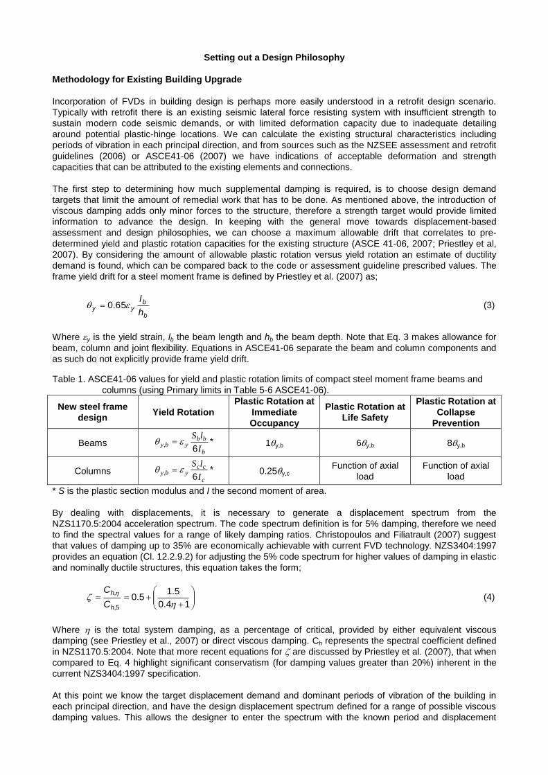
frame yield drift for a steel moment frame is defined by Priestley et al. (2007) as;
b
byy
h
l 65.0 (3)
Where y is the yield strain, lb the beam length and hb the beam depth. Note that Eq. 3 makes allowance for
beam, column and joint flexibility. Equations in ASCE41-06 separate the beam and column components and
as such do not explicitly provide frame yield drift.
Table 1. ASCE41-06 values for yield and plastic rotation limits of compact steel moment frame beams and
columns (using Primary limits in Table 5-6 ASCE41-06).
New steel frame
design Yield Rotation
Plastic Rotation at
Immediate
Occupancy
Plastic Rotation at
Life Safety
Plastic Rotation at
Collapse
Prevention
Beams b
bbyby
I
lS
6, * 1y,b 6y,b 8y,b
Columns c
ccyby
I
lS
6, * 0.25y,c
Function of axial
load
Function of axial
load
* S is the plastic section modulus and I the second moment of area.
By dealing with displacements, it is necessary to generate a displacement spectrum from the
NZS1170.5:2004 acceleration spectrum. The code spectrum definition is for 5% damping, therefore we need
to find the spectral values for a range of likely damping ratios. Christopoulos and Filiatrault (2007) suggest
that values of damping up to 35% are economically achievable with current FVD technology. NZS3404:1997
provides an equation (Cl. 12.2.9.2) for adjusting the 5% code spectrum for higher values of damping in elastic
and nominally ductile structures, this equation takes the form;
14.0
5.15.0
5,
,
h
h
C
C (4)
Where is the total system damping, as a percentage of critical, provided by either equivalent viscous
damping (see Priestley et al., 2007) or direct viscous damping. Ch represents the spectral coefficient defined
in NZS1170.5:2004. Note that more recent equations for are discussed by Priestley et al. (2007), that when
compared to Eq. 4 highlight significant conservatism (for damping values greater than 20%) inherent in the
current NZS3404:1997 specification.
At this point we know the target displacement demand and dominant periods of vibration of the building in
each principal direction, and have the design displacement spectrum defined for a range of possible viscous
damping values. This allows the designer to enter the spectrum with the known period and displacement
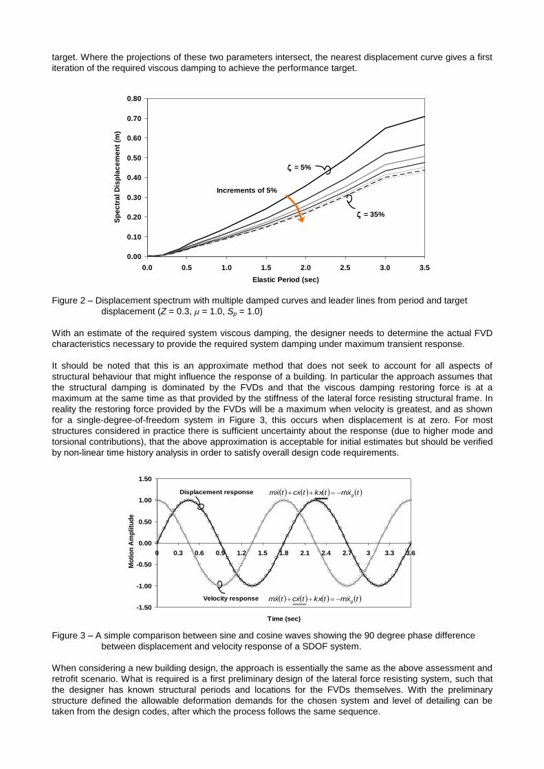
target. Where the projections of these two parameters intersect, the nearest displacement curve gives a first
iteration of the required viscous damping to achieve the performance target.
Figure 2 – Displacement spectrum with multiple damped curves and leader lines from period and target
displacement (Z = 0.3, = 1.0, Sp = 1.0)
With an estimate of the required system viscous damping, the designer needs to determine the actual FVD
characteristics necessary to provide the required system damping under maximum transient response.
It should be noted that this is an approximate method that does not seek to account for all aspects of
structural behaviour that might influence the response of a building. In particular the approach assumes that
the structural damping is dominated by the FVDs and that the viscous damping restoring force is at a
maximum at the same time as that provided by the stiffness of the lateral force resisting structural frame. In
reality the restoring force provided by the FVDs will be a maximum when velocity is greatest, and as shown
for a single-degree-of-freedom system in Figure 3, this occurs when displacement is at zero. For most
structures considered in practice there is sufficient uncertainty about the response (due to higher mode and
torsional contributions), that the above approximation is acceptable for initial estimates but should be verified
by non-linear time history analysis in order to satisfy overall design code requirements.
Figure 3 – A simple comparison between sine and cosine waves showing the 90 degree phase difference
between displacement and velocity response of a SDOF system.
When considering a new building design, the approach is essentially the same as the above assessment and
retrofit scenario. What is required is a first preliminary design of the lateral force resisting system, such that
the designer has known structural periods and locations for the FVDs themselves. With the preliminary
structure defined the allowable deformation demands for the chosen system and level of detailing can be
taken from the design codes, after which the process follows the same sequence.
-1.50
-1.00
-0.50
0.00
0.50
1.00
1.50
0 0.3 0.6 0.9 1.2 1.5 1.8 2.1 2.4 2.7 3 3.3 3.6
Time (sec)
Mo
tio
n A
mp
litu
de
Displacement response
Velocity response txmtkxtxctxm g
txmtkxtxctxm g
0.00
0.10
0.20
0.30
0.40
0.50
0.60
0.70
0.80
0.0 0.5 1.0 1.5 2.0 2.5 3.0 3.5
Elastic Period (sec)
Sp
ec
tra
l D
isp
lac
em
en
t (m
)
= 5%
= 35%
Increments of 5%
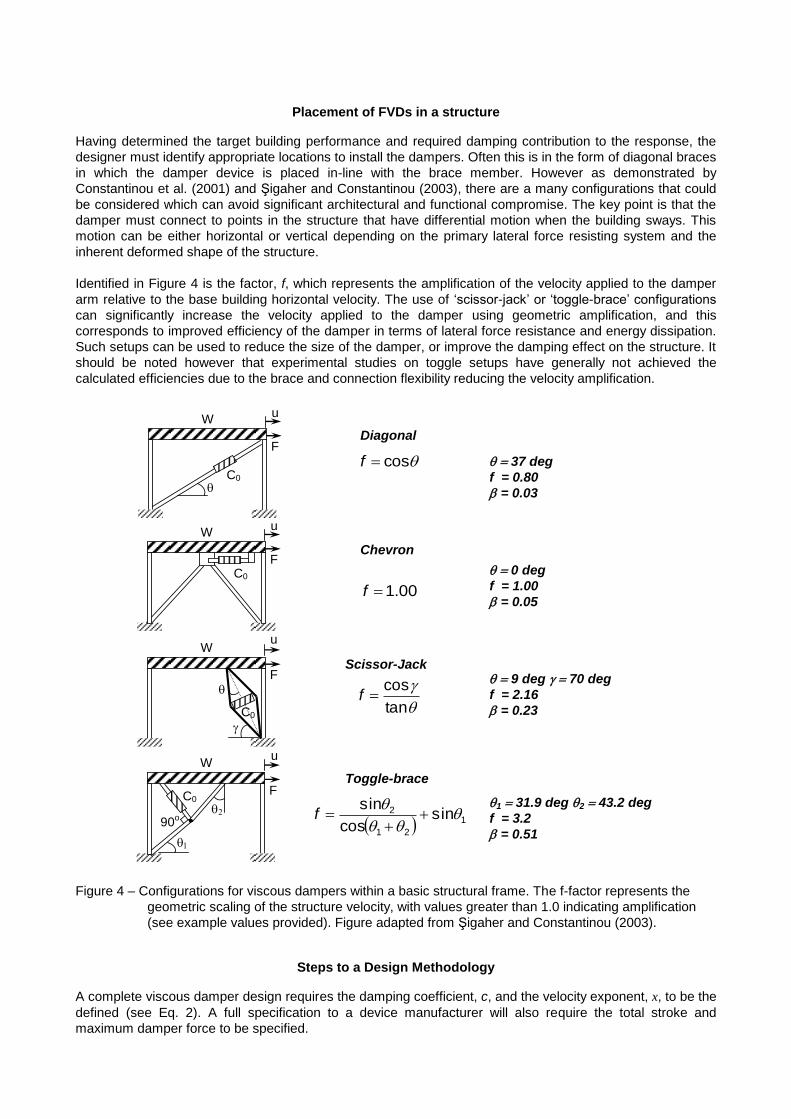
Placement of FVDs in a structure
Having determined the target building performance and required damping contribution to the response, the
designer must identify appropriate locations to install the dampers. Often this is in the form of diagonal braces
in which the damper device is placed in-line with the brace member. However as demonstrated by
Constantinou et al. (2001) and Şigaher and Constantinou (2003), there are a many configurations that could
be considered which can avoid significant architectural and functional compromise. The key point is that the
damper must connect to points in the structure that have differential motion when the building sways. This
motion can be either horizontal or vertical depending on the primary lateral force resisting system and the
inherent deformed shape of the structure.
Identified in Figure 4 is the factor, f, which represents the amplification of the velocity applied to the damper
arm relative to the base building horizontal velocity. The use of ‘scissor-jack’ or ‘toggle-brace’ configurations
can significantly increase the velocity applied to the damper using geometric amplification, and this
corresponds to improved efficiency of the damper in terms of lateral force resistance and energy dissipation.
Such setups can be used to reduce the size of the damper, or improve the damping effect on the structure. It
should be noted however that experimental studies on toggle setups have generally not achieved the
calculated efficiencies due to the brace and connection flexibility reducing the velocity amplification.
Figure 4 – Configurations for viscous dampers within a basic structural frame. The f-factor represents the
geometric scaling of the structure velocity, with values greater than 1.0 indicating amplification
(see example values provided). Figure adapted from Şigaher and Constantinou (2003).
Steps to a Design Methodology
A complete viscous damper design requires the damping coefficient, c, and the velocity exponent, x, to be the
defined (see Eq. 2). A full specification to a device manufacturer will also require the total stroke and
maximum damper force to be specified.
C0
W u
F
C0
W
F
u
C0
W
90o
u
F
C0
W u
F
00.1f
cosf
tan
cosf
1
21
2 sincos
sin
f
Diagonal
Chevron
Scissor-Jack
Toggle-brace
37 degf = 0.80
= 0.03
0 degf = 1.00
= 0.05
9 deg 70 deg f = 2.16
= 0.23
131.9 deg 243.2 deg f = 3.2
= 0.51

Determination of the required damper characteristics can be achieved by a number of means. There is a
significant amount of literature available; however designers have been left to guess the distribution of
damper parameters within the structure. With iteration such an approach can produce a sensible design,
however it relies on significant design experience to efficiently start, and then arrive at an optimal solution.
As noted in the previous section, a preliminary sizing of the structural members is necessary along with the
target performance characteristics. Knowing the target system damping, an initial design of the structural
members can be carried out by reducing the design acceleration spectrum using Eq. 4 with the target
damping ratio. Having reduced the spectrum, the initial design can proceed in the same fashion as normal
practice following NZS1170.5:2004. Because the following steps require a numerical model of the structure, it
makes sense to follow a multi-modal analysis and design procedure at this point, although an Equivalent
Static Analysis would be acceptable if the building meets the usual code limitations for this approach.
For new designs, Capacity Design should still be applied at this stage, as this builds a level of conservatism
into the lateral force resisting system that allows for the assumptions on the phasing of the viscous damping
restoring forces relative to the structural frame restoring forces.
Christopoulos and Filiatrault (2006) present a simple method to determining an initial distribution of damper
properties for a pre-determined damped frame system, where the location of the damping devices is known.
This initial distribution can then be refined by the designer to capture particular aspects of response that
become apparent from the time history verification. This approach will be briefly summarised to familiarise the
reader with the intent, however it is beyond the scope of this paper to fully replicate it here.
The method described by Christopoulos and Filiatrault (2006) provides a distribution of linear ( = 1.0)
viscous damper coefficients that follows the distribution of storey stiffness over the height of the building, and
therefore maintains a stiffness proportional damping matrix. This is useful as the modal properties of the
structure remain essentially constant when the damper elements are introduced in the computer model.
While this approach is based on linear viscous damper properties, it is also useful for initial estimates of non-
linear damping constants.
To carry out the distribution analysis it is necessary to determine the storey stiffness at each level in the
structure, from which a set of fictitious springs are introduced at locations where the dampers will eventually
be added to the numerical model. With one iteration of the fictitious spring stiffness values, the designer can
determine the damping coefficients for each damper location using the relation:
iLi cT
k ,1
,0
2 (5)
Where k0 is the fictitious spring stiffness at location i, T1 the first mode period of the structure in the direction
being considered and cL,I the FVD coefficient at location i.
Once the distribution of cL,I is confirmed, the structural model can be updated with damping elements
(typically defined as dashpots in common structural analysis packages) carrying these characteristics. If non-
linear damping behaviour is sought then adjustments to the value of are carried out by trial and error.
Verification
Because a lateral force resisting system using supplemental viscous damping is considered undefined in
NZS1170.5:2004 and NZS3404:1997, it is necessary to carrying out non-linear time history analysis to
confirm that the primary structural system responds as expected, and that the fundamental clauses of the
codes are met.
Assuming that the preliminary design, determined earlier with the reduced Zone factor (Z) satisfies the force
demands and deformation limits of the codes, the first verification step should be to check the effective
damping of the system. This can easily be achieved using a snap-back analysis to set the numerical model
structure into damped free vibration (Chopra, 2007).
If the system damping is approximately equal to the target damping, then the non-linear time history analyses
can proceed following the requirements of NZS1170.5:2004. The focus of this phase will be to confirm that

the base structure meets performance objectives such as ‘limited’ or ‘no’ inelastic structural action (in
keeping with LDD philosophy), and that the code or project specific deformation limits are maintained. At the
same time the designer can extract the required FVD force capacity, the peak velocity achieved and the
maximum stroke requirements.
In large buildings the damper forces can be significant, and the designer must check with potential suppliers
of the devices that such capacities can be readily achieved, and that the size of the device is reasonable for
the structure. If the device specification is too big for the application (noting that bridge dampers can be very
large and with high capacity, but impractical for building applications) then the designer will need to re-assess
the number and distribution of devices, or the building performance targets and the system damping required.
Similarly the designer must check that the structural framing can sustain the forces imparted by dampers
such that unintended yielding does not occur.
To adequately follow the procedure described in this paper, the design should to be familiar with the basic
principles of Displacement-Based Design (for example that presented by Priestley et al., 2007), and be
comfortable with using deformation limits such as those in NZS3404:1997 or ASCE 41-06 (example in Table
1). With these tools in-hand the procedure for determining the required damping coefficients follows with
rapid convergence.
An Example of Practical Application
A brief 2-dimensional example is provided here to demonstrate the process described above. We will take a
new three storey steel moment frame (Figure 5) office building (Importance Level 2) with fixed column bases,
for which we are targeting a 0.75% maximum storey drift at the Ultimate Limit State (ULS) to ensure that with
specific detailing the non-structural damage will be limited, as will damage to the floor diaphragms. The
design intent is to maintain essentially elastic behaviour ( = 1.0) in the frame members (defined as Category
2 members to ensure a level of ductility is provided for when detailing the connections), with all energy
dissipation occurring in the FVDs, which for simplicity we will apply in-line as a single diagonal brace at each
storey.
Figure 5. Moment Resisting Frame with preliminary member sizes determined using a Zone Factor reduced
to account for the expected supplement viscous damping.
Rearranging the approximate equation for yield drift of a steel moment frame given by Priestley et al (2007)
we can determine our maximum beam depth that will provide a yield drift greater than or equal to the target
drift of 0.75%. If we can ensure this behaviour, then essentially elastic performance should be achieved. The
resulting beam depth is given by:
mmMPa
MPalh
y
byb 1040
0075.0
8000
200000
30065.065.0
(6)
Knowing the target peak displacement at the effective height of the frame (0.7hn is approximately the second
floor assuming a linear displacement profile of the building), and an approximate first-mode period of 0.6
seconds, we enter the displacement spectrum in Figure 2, from which our target system viscous damping
410UB82
610UB125
610UB125
350W
C258
350W
C258
350W
C258
350W
C258
FVD to be determined

ratio is chosen to be 25%. Note that this value includes the inherent 5% assumed in the code definition of the
spectrum, therefore our target supplemental damping is 20%.
At this point we carry out our preliminary design using a reduced Z factor (for 20% damping) to calculate the
design base-shear of 2013 kN, following NZS1170.5:2004.
The beam design moments are calculated, and the required sections chosen to satisfy the moment demand,
while maintaining a depth of 1040 mm or less. The beams are chosen to be 610UB125 at levels one and two,
460UB82 at roof level, and the columns 350WC258 at all levels.
We check the first mode period is similar to that previously assumed, and in finding negligible difference,
proceed with the method described by Christopoulos and Filiatrault (2006) using the value of 20% damping.
For simplicity the velocity exponent is kept equal to 1.0, so the resulting distribution of damper coefficients is
given in Table 2.
Table 2. Summary of fictitious spring stiffness and resulting FVD properties using described by Christopoulos
and Filiatrault (2006), and verified by non-linear time-history analysis.
Calculated prior to VerificationObtained from Verification
Analyses
Level k0,i cL,i Max Damper
Force Stroke
kN/m kNs/m kN mm ±
L3 33259 3245 1.0 587 19
L2 46051 4493 1.0 923 22
L1 59866 5841 1.0 1070 17
We add the dampers to our structural model as diagonal dashpot elements (checking that the modal
characteristics have not changed significantly), at which point the non-linear time history analysis verification
can proceed following the requirements of NZS1170.5:2004. Checks on storey drift, local rotations and force
demands are primarily used to identify code compliant performance, while peak damper forces, strokes and
velocities are extracted in order to provide full specification for the device manufacturer.
Note that the “inherent” system viscous damping was modeled using initial stiffness Rayleigh Damping, with
5% damping assigned to 0.1T1 and 1.5T1. A “snap-back” analysis was used to confirm the actual system
damping under free vibration. The result from this indicated an effective system damping of 29% which slight
larger than intended, but as seen in Figure 2 does not significantly change the maximum response of the
structure.
Figure 6 provides a 20 second time history comparison between the viscous damped frame, and a
commensurate ductile frame (designed with = 3). The time history plots show the first storey drift, base
shear, first floor damper force and first floor damper stroke from the Imperial Valley 1940 El Centro record to
highlight the response characteristics. Also included is the envelope profile for each of these responses (from
three code scaled records), which would be used to characterize and specify the building performance. It is
worth noting that the conventional frame developed plastic hinges in most beams and column bases
(average ductility demand 2.5) while the FVD frame remained elastic and therefore suffered no structural
damage. In keeping with the intention of LDD using the FVD system, the drifts and accelerations are low
enough that non-structural damage would be at a minimum based on these results.

Figure 6 - Time history comparisons between a conventional ductile ( = 3 and 5% Rayleigh damping)
moment frame and low damage design viscous damped frame ( = 1 and 5% Rayleigh Damping
+ 20% supplemental damping). The storey maximum plots (on the right) are the envelope plots
from three code scaled spectrum compatible records which characterize the overall building
performance and specification for the dampers.
Conclusions
The use of viscous damping to control and improve building performance has been well demonstrated by
numerous researchers and designers internationally. With the move towards Low Damage Design of
structures in New Zealand, the combination of essentially elastic seismic resisting frames and fluid viscous
dampers provide an opportunity to accurately achieve a high level of performance at multiple limit states, and
for a wide range of building forms. This paper has summarized a practical design approach that takes a step
towards true performance-based design. A simple three storey moment frame example has been included to
demonstrate the method, with results that clearly identify the benefits of supplemental viscous damping in
terms of controlling drifts and accelerations in the building.
-0.8%
-0.6%
-0.4%
-0.2%
0.0%
0.2%
0.4%
0.6%
0.8%
0 2 4 6 8 10 12 14 16 18 20
Time (sec)
Fir
st
Sto
rey
Dri
ft (
%)
MRF 5% Damping
MRF 25% Damping
-12000
-8000
-4000
0
4000
8000
12000
0 2 4 6 8 10 12 14 16 18 20
Time (sec)
Ba
se
Sh
ea
r (k
N)
-1200
-900
-600
-300
0
300
600
900
1200
0 2 4 6 8 10 12 14 16 18 20
Time (sec)
Da
mp
er
Fo
rce
(k
N)
-0.020
-0.015
-0.010
-0.005
0.000
0.005
0.010
0.015
0.020
0 2 4 6 8 10 12 14 16 18 20
Time (sec)
Da
mp
er
Ex
ten
sio
n (
m)
0
1
2
3
0.0 0.5 1.0 1.5
Acceleration (g)
Flo
or
0
1
2
3
0.0% 0.5% 1.0% 1.5%
Storey Drift (%)
Flo
or
0 400 800 1200
1.0
2.0
3.0
Flo
or
Max Damper Force (kN)
0.000 0.005 0.010 0.015 0.020 0.025
1.0
2.0
3.0
Flo
or
Max Damper Extension (m)

References
ASCE Standard (ASCE/SEI 41-06), 2007. Seismic Rehabilitation of Existing Buildings, American Society of
Civil Engineers, Virginia, USA.
Chopra, A.K., 2007. Dynamics of Structures: Theory and Applications to Earthquake Engineering, 4th Ed.,
Prentice-Hall, USA.
Christopoulos, C. and Filiatrault, A. 2006. Principles of Passive Supplemental Damping and Seismic Isolation,
IUSS Press, Pavia, Italy.
Constantinou, M.C., Symans, M.D., and Tsopelas, P. 1993, Fluid Viscous Dampers in Applications of Seismic
Energy Dissipation and Seismic Isolation, ATC17-1: Seismic Isolation, Passive Energy Dissipation
and Active Control, 2, pp581-591.
Constantinou, M.C., Soong, T.T. and Dargush, G.F., 1998. Passive energy dissipation systems for structural
design and retrofit. Monograph #1, Multidisciplinary Center for Earthquake Engineering Research,
University of Buffalo, Buffalo NY, USA.
Constantinou, M.C., Tsopelas, P., Hammel, W. and Şigaher, A.N. 2001, Toggle-brace-damper seismic
energy dissipation systems, Jrnl. Struct. Eng. 127(2), pp105-112.
Hanson, R.D. and Soong T.T., 2001. Seismic design with supplemental energy dissipation devices.
Earthquake Engineering Research Institute, Oakland CA. USA
New Zealand Standard (NZS3404:1997), Steel Structures Standard, Standards New Zealand, Wellington.
New Zealand Standard (NZS1170.5:2004), 2004. Structural Design Actions Part 5: Earthquake Actions –
New Zealand, Standards New Zealand, Wellington.
NZSEE Study Group on Earthquake Risk Buildings, 2006, Assessment and Improvement of the Structural
Performance of Buildings in Earthquakes, New Zealand Society for Earthquake Engineering,
Wellington.
Park, R. and Paulay, T., 1975. Reinforced Concrete Structures, John Wiley & Sons, New York, USA.
Paulay, T. and Priestley, M.J.N. 1992. Seismic Design of Reinforced Concrete and Masonry Structures,
Wiley, John Wiley & Sons, New York, USA
Priestley, M.J.N., Calvi, G.M. and Kowalsky, M.J. 2007, Displacement-Based Seismic Design, IUSS Press,
Pavia, Italy.
Şigaher, A.N. and Constantinou, M.C., 2003, Scissor-Jack-Damper Energy Dissipation System, Earthquake
Spectra 19(1), pp133-158.
Symans, M.D. and Constantinou, M.C. 1998, Passive fluid viscous damping systems for seismic energy
dissipation, ISET Journal of Earthquake Technology 35(4), Special Issue: Passive control of
structures, pp185-206.
Symans, M.D., Charney, F.A., Whittaker, A.S., Constantinou, M.C., Kircher, C.A., Johnson, M.W. and
McNamara, R.J. 2008, Energy Dissipation Systems for Seismic Applications: Current Practice and
Recent Developments, Jrnl. Struct. Eng. 134(1), pp3-21.