Change 2,Rev 4 to Procedure OP2347B, "Normal Station Svc ...
18
_ ..... w a n --- Y: 8thf a i ri: ' - . Fors App en/gy 5tatippuperintendent Effective Date - $1AT10h Pe0CEDutt OR F0tp CNANCE ( ' - . . A. 10!WTIFICAT]DN 1 1 PROCEDURE OR FORM NLMBER OO[349 b REV. 4 b ' CMMIGE 80. . .I (Circle One) . s . PROCEDutt QR FotM TITLE w <C<rc's One) isc -2,s e u. a.r y INITIATED BY_ O* > _O . . . . . * = g C. REASON FOR CHANCE h% | g% W Af , o 189 -o 2 -d g . . - D. a04-INTENT CNueCE AUTHORIZATION (K/A for Intent Changes) - - r . : , . TITLE 11CRATutE SATE Shift Seervisor (en duty) . E. REVIEWED | SePartment Mead f, & _ ,1, . ' finreviewed safety Questien tva tien noementation teosired: ' ' (51gnificant cha in procedwre method er scope i ( as describes in SAR) []TES [ W - (If yes, doceent in P0tC/50tC meeting ofnetes) ' DrvitoesqENTAL !wACT '(Adverse envirormental teact) { ] VES [ , (If yes, doceent in P0tc/50RC asettag afnetes) -f.-N/50tc SECOs00e1 APPRDVAL1er tentfruatten nfinterfe dange erf9fn144) , P0tC/50RC Heetf ag Ember ,"J '-ENO 4. APPt0 VAL me 1*LDENTATION The change is hereby feptemented and is effectfee tAfs este escept for letarle re laplemented and effective per the AutherI3atten of 3 above. .L changes Wleh SM skhv ; . . L. 5tation printaneset/ unit zeerley .pste _ - - - -. . - - . , . , .: . . . . . ;, " ' W -3EE '. . . %.. . . [ .., / - - .. -- - . Ase. 6 .- r - - , .g,. . . ; . 84122 0285 e41204 ,.;,.. peg,gerg;, 1 .g - ,...~.,y.. t - PDR A OCK 0500033 . .. : f Q '. h :. & 3. c. n , .,'t.' :~Q.+ . .?,)y . ,ffkfD . . . . ~ . - - . . . . . . PDR . . ..s . , Q..a - N u. - .. , , . - . .' . - . - __- _ - ...-. _ ..- - - -..- _ - _ _ -;.LI)* : 2. 2.Qr - P pm.T : .:. : 4.- . ~. . . g, . , ' *: _ ,. . _ _ _ _ _ . _ . . - . - - .
-
Upload
khangminh22 -
Category
Documents
-
view
0 -
download
0
Transcript of Change 2,Rev 4 to Procedure OP2347B, "Normal Station Svc ...

_..... w a n ---
Y: 8thf a i ri:'
-.
Fors App en/gy 5tatippuperintendent Effective Date- $1AT10h Pe0CEDutt OR F0tp CNANCE (
'
-
. .A. 10!WTIFICAT]DN
1
1 PROCEDURE OR FORM NLMBER OO[349 b REV. 4 b '
CMMIGE 80.. .I (Circle One) . s.
PROCEDutt QR FotM TITLE w<C<rc's One) isc -2,s e u. a.r y
INITIATED BY_ O* > _O.
.
. .
. * =g
C. REASON FOR CHANCE
h% |g% W Af , o 189 -o 2 -dg
.
.
-
D. a04-INTENT CNueCE AUTHORIZATION (K/A for Intent Changes) - -
r .: , .
TITLE 11CRATutE SATE
Shift Seervisor (en duty)
.
E. REVIEWED
| SePartment Mead f, & _ ,1,.
'finreviewed safety Questien tva tien noementation teosired:' '
(51gnificant cha in procedwre method er scopei
( as describes in SAR) . []TES [ W -
(If yes, doceent in P0tC/50tC meeting ofnetes)'
DrvitoesqENTAL !wACT
'(Adverse envirormental teact) { ] VES [ ,
(If yes, doceent in P0tc/50RC asettag afnetes)
-f.-N/50tc SECOs00e1 APPRDVAL1er tentfruatten nfinterfe dange erf9fn144),
P0tC/50RC Heetf ag Ember ,"J '-ENO
4. APPt0 VAL me 1*LDENTATION
The change is hereby feptemented and is effectfee tAfs este escept for letarlere laplemented and effective per the AutherI3atten of 3 above.
.L changes Wleh SM skhv; .
. L. 5tation printaneset/ unit zeerley .pste_ - - - -. . - - . ,.
,
.: . . . . .
;," ' W -3EE '. . . %.. . . [ .., / --
.. -- - . Ase. 6 .- r - -
, .g,..
.
; . 84122 0285 e41204 ,.;,.. peg,gerg;, 1 .g -,...~.,y..t - PDR A OCK 0500033
.
..
: f Q '. h :. & 3. c. n , .,'t.' :~Q.+ . .?,)y, 3. ..?,. ,ffkfD. . . . ~ . - - .. . . ..
PDR . . ..s. , Q..a -
N u.-
.. , , . - . .'. - . - __- _ - ...-. _ ..- - - -..- _ -
_ _ -;.LI)* :2. 2.Qr - P pm.T : .:. : 4.- . ~. . . g, . , '*:_
,. .
_ _ _ _ _ . _ . . - . - - .

,.
o .
kf /2-l-160*~' -
.- *
,, rem w .om sutiegsperinseneens terective se u...
,
y [ STAT]Dh Pe0!ED0t! 08 toes CHAEt |j*
d
C o bjV A. seccitiemoM'
#p. no:toat os rov u>stt 0/ 23 4 '?8 ttV. 4 cut ao.L. >-
ij (Circle One) '
i .. .~
PtoCED#l QR FORM TITLt M / 6ed, Tw ~' '
,.
' $ us$N?e?|2.D.($ W $ " '''A '
..-.
m e. e.cr ,
p &/ .dw'|~ aa,
/
1
4
.,
2 j.. .,
C'-.
c. etaso= ron ewAnct '
YtwA y .%-- ce osGV-o 2. "OPn. --
Pm PM atz)& Adw
-c9n s . askAd & r p~$p J Ay"
-
$ O ? 2 3 4Q 0 * -
( C -
'
D. 90=-!WTENT CMAnct ALTiMoellATion (h/A for Intent Changes) -
.
TITLt $1CxATURE Ei Shift Seerviser fan duty)
.
j. E. REV1ttfED.
,
- - (J ft" - y ai.* *
t previewed Safety tfen tvaluettom Doceentatten Roosited:._" ' " '
(5fentricant the Wprocedwre method er scopeas described in Sat) { } TES [[W
- u
(If yes, doceent in P00C/500C netting minuten),
!
I twitoetWTAL teACT -
|'(Adverse envfremental fspect) ( ) Vis ([W ,
I (If yes, decaent in P0tC/50tc emetfag minutes)
| --F. -90tC/50tC SEC09005 -APPSDVAL Ter sanffrustfen sfistarfsDenge wit &1s-14 stys)' ~"
.
90tC/50tC Restfng Emberh*b *k
i S. APPtevAt Ale leLDEWTATIon
The f.henge is hefgby fgfamented and is effective thfs date, encept for laterles umf f T nted and af fee per the Awt&orfastion of 8 above. - .
<||P/ * * ~ ~ 't
i-
. .. . .. . -i-? . , .1.. .- . . .. . .. .. statten seetretenenavunit zoettsteesset .meta. . - - - -- _
. . ..
,' .n -
: . . . .. ...'
1 k. s ~. . .;;. . . -.- ,
1 r ggg, g er g . . . ,; -. . . . ... .
-. ..t. ; .?,. .'.'.: ?.'';;.' .-9.. . ,'|- *
. . . ' . :- - -..
. .. . . ~ ~ - . < ... .....r. ..- .
. . . . . .;. ..... .
; , ,. : L... .:w.c :a. :_.. - _ .-. ';_ .--- .-..
. .. y.: c.~;.M ..; ;t.7 :;, . :,: ;.t.._ i3,.s. ;.a.;Q:,.$._~.:5.c, .. . :. ;. . . . a. .:'
. . . . ... .
._ . _ _ _ _-

.-
ATTACHMENT TO GEE-84-1311~. 8., . ,,
,. -
||'
~
,
t F *.U 0S E E F P.'I S I 0t TO OF2347B,
,
( 3
1. C .anec i te , "E.2 f..$ . 5.1. Unde rvol t age", to i ten B.2 (b)- s , . -
2. Add nen- iter. S.2(a) to read as follows: '
* 6.2 (a) N.S.S.T. Degraded Vol tage ' C04L CA-8.
,vr
initiating Device set Point
Computer Print- 342g yEE032
. Bus 24 A/B (4.16KV)
Action'
'
Auto *
1. None'
initial
!
1. Verify proper operation of the turbine generator and itsexciter per Procedure OP3234A.
( 2. Verify actual degraded voltage condition by observation of .
'
L bus voltmeters. '
Bus 24A, B, C, D, s E 3620VBus 22E s F 424V
,,
|'
3 If possible reduce affected busses loads to increase voltage. -.
4. (a) Call Convex to raise 24'tV Cenerator Voltage / Increase VAR| output. .. ..
| - -A..i
.
4. (b) Call Convex to raise system voltage. T,,"| 5 Inform Duty officer if Degraded voltage persists.
900TE: ^ T/ff".ssber DL42RDRTJonl Vol74'6 FOR JAfETY"
ElLRT&O MOTod,$ TS aff % of 99Y68 V0ZT$dd,.TW6 7.rMd LIM 27~ $ Y 7'41:s $4s79st Bffdd-toggpyggggy-pggggy yg ;9 ppg gggy 7 f,y . .
*
4 No02s,j . -
.
.
e
Q .. . . . - - . --- -- *.
! . .t . -.
-
. . _ . _ _ . . _ . . . . .. - - - - - - - - ' " ~ ~'
*.9. #
a,a. ,.p
! I :ec.:m|i'2h. '4 - | *. ?R4*?! k NO:. - - . _ . . , _ , . - - , _ __ _
.
.' tg~
ATTACHMENT TO GEE-84-1311.*. . Pcga 2..
, c.
.,>.
(' ' .
.
.i Subsecuent.,
-
? .
1. Determine cause of degraded voltage condition and log '
reason, action taken, and time period taken to restore'' normal voltage.
.
.
.
.
,..
tjc)
T.
3q'<i
,
.
NTT/psn '
3, .
.
g..,
5/17/84.
.
-
.
-.
.
. L;.wy:$'ja . g, . -
.,
: it ,, .. - <;;;.
,
, , ,
.
.
..
.... ._ _. . . . - . . . . . . - . -. - - - - - - - - - - . . . _ - _ . . .. .----- - - - - - - - - - - - - - -4
. -
' y #a
*. . afq . a,.~ ~ .. s
*g
.,,s , ,e=n:ww. ," -:, . q;r . : '- .
- -:::w. ;- t . t . . YN ''' +' ._ ,~, ~ . ., .- , - d:hdr,,;ddh.h*hhQ)).h.~%1L[.. ..a
~
. 8M'
-
oa.> |.\s-
'
E.J. Mroczka 12-28-81' '
( Form Approved by Station Superintendent Effective Oste' 'i*
j;-
.,.
~ STATION PROCEDURE COVER SHEET '. l' -
y ;;
A. IDENTIFICATION j.
'|
Number OP 2347B Rev. 4_'
>>
Title Normal Station Service Transformer 15G-2S (N.S.S.T.)
Prepared By R. Burnside~
B. REVIEW,
I have reviewed the above procedure and have found it to be satisfactory.~
TITLE SIGNATURE DATE a--
/!f!bDEPARTMENT HEAD
i)
.
C. UNREVIEWED SAFETY QUESTION EVALUATION DOCUMENTATION REQUIRED:
I( (Significant change in procedure method or scope -
as described in FSAR) YES [ ] NO #,
(If yes, document in PORC/SORC meeting minutes)|'
ENVIRONMENTAL IMPACT
(Adverse environmental impact). YES [ ] NO W +'
(If yes, document in DORC/SORC meeting minutes)
1 D. PORC/SORC APPROVAL~
.$, _
-PORC/60RC Meeting Number d-83-I N[i' ?., .
^'E. APPROVAL AND IMPLEMENTATION
The attached procedure is hereby approved, and effective a the date below:
/|LOfb'b'
H. G5tation/S1|lirvice/ Unit Superintendent Effe'ctive Date
.
SF-301t
! Rev. 5
|
| r
.
:
,
;h'i#'* $Y, , . _ . , .
_ )$$ igi b'-. :,..' ' h|. |t ,. , .* * ' Ni; :
.. ._.
.*s
OP 2347B Paga 1-
.' Rev. 4'
'
<. .
~
UNIT 2
NORMAL STATION (ERVICE TRANSFORMER 15G-25 (N.S.S.T.) .'
:
b
k
PAGE NO. EFF. REV. -,
,
1-13 4
.
r
3
4
0 *
i h*
C -
:I
: #
,..
,-
-. || -- ".|~4 )c
.,
.J
e
h
a
!-
; - C..
& 'ys e,
? g, --
.
' '( h' ' 'kb$. /.kh$[hAb 14i;;;,. '3 +' [ a5 fl7 + = ~ .,_db . . ....
.
.
.. .. .'
OP 2347B Paga 2.
*-
- Rev. 4-;
-. ,
-
<..
' (|
.
>.
.
, ,
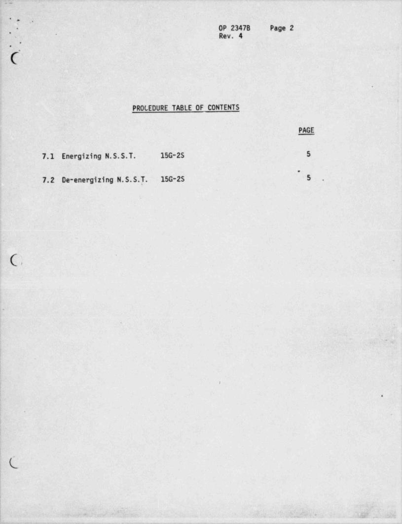
PROLEDURE TABLE OF CONTENTS :,
1
* 1
PAGEs
7.1 Energizing N.S.S.T. 15G-25 5
7.2 De-energizing N.S.S.T. 15G-25 5 ...I
C -
.
_
'
<
,'' ,54 7
t
'
i
|
r i
!
| .
-.
|
|
. C.,
-
;
|
I
I
,
'
'
j , * * e b
^
Q* . 4
} ' , ? -2,) ' Y. a y , , q| , f' f,
;' . , . ' 5 "" }4 _,33 _ , ,_ j}};
. _ _ _ _ _ _ . - . . - . . . ._ - _ _ _ . _ . _ . _ . _ . _ . , _ _ _ _ - _ , . - . _ - _ , . . _ _ _ ' . . _ _ _ _ ' _ _ - _ _ _ . _ _ _ - , . .
_ -- -

-. - - .-
_
. , ,
*- OP 23478 Paga 3. .' '
Rev. 4j - ,
-i*.
1. -0BJECTIVE
1.1 To provide a procedure for startup, shutdown, normal and,
casualty operations of the Normal Station Service Transformer .
y , (N.S.S.T.).,
2. LICENSE REQUIREMENTS
2.1 Refer to Technical Specifications 3/4.7.1
3. REFERENCES
3.1 F.S.A.lh Chapter 8.*
y. i,'
4. PLANT OPERATING REQUIREMENTS
4.1 The N.S.S.T. is the preferred source of 6.9-KV and 4.16-KV'
power during Turbine Generator at power operations.
5. PREREQUISITES
5.1 125 VDC control power in service.
'( 5.2 Station relaying available as required.~
5.3 Telephone communications as required.5.4 Cooling Supply Power from MCC 22-2A and MCC 22-1DA is available'
and Cooling Control in Automatic.|
'
5.5 Data Logger Computer in service (desired). -
| 5.6 N.S.S.T. N2 Gas bottles pressure between 500 psig and 2000 psigand gas system in service. Normal tank pressure range 1.0 psig - _
w.
i - &to 1.5 psig., .' 5.7 Verify Transformer Deluge System available for service.
6. PRECAUTIONS
6.1 Before racking out any low side breaker, check to make sure the ,
breaker is open.,
'
6.2 Do not close breakers locally without contacting Control RoomOperator.
6.3 Check switching and tagging log to assure clearance of all tags
,on equipment to be energized.
L
r;.ar ,.
h s, %~ * n . .-.r . . .J ]. L 'p'|.
:j Q *___ _ Q- , , ...~..-.-,.. - .- ,,,.- .- . - .-..---...--. --- _----.- -- --..------__ .

. . . . _ - . . __ .- - _.
. , ,.
OP 2347B Paga 4*
. ,' Rev. 4
,.
'*. ,
b 6.4 Before energizing any equipment following maintenance, a visualinspection will be made to ensure that all portable groundshave been removed, all bus compartment panels have been replaced, .
, ,all breakers on the equipment are open, all foreign objects
,
from in and around the equipment have been removed, all protective
relay targets are reset, potential transformer fuses are;
installed and all compartment doors are closed.'
i 6.5 N.S.S.T. will be energized anytime the turbine generator isenergized, except whenever the isolated phase links between thegenerator terminals and N.S.S.T. terminals have been removed. .
6.6 For forced-oil-cooled (FCA or F0W) transformers with all pumpsor fans or both inoperative, the following operating conditions
; are assumed to occur infrequently and without undue damage to . <
the transformer:1. Rated load may be maintained for approximately 1
(one) hour following normal operation at nameplate.
,'. rating at 30*C ambient.
( 2. Rated load may be carried for approximately 2 (two) -'
hours if started with the windings and oil at 30*C
l - ambient.I 3. Rated voltage may be maintained for 6 (six) hours at
no load, following continuous operation at nameplaterating at 30*C ambient with cooling equipment inoperation. . .
4. Rated voltags may be maintained for 12 hours at no-
load starting with the windings and oil at 30*C'
i ambient.6.7 For forced-oil-cooled transformers (FOA or F0W) ratings with
part of coolers in operation, use the following: ,
Table 92.01 - 244% of Total Coolers in Operation Permissible Load in %
-
of Nameplate Rating.c ' '
100 100*
80 90
b 60 78
,
bL
! - ,-
. gg9. a: , as .?: [.,_ , ,
,
_ _ _ . . . _ - _ - , . _ . . _ - . _ . _ _ . . . _ , _ - - - _ . _ _ _ . _ _ _ _ _ _ _

. ._
_,
.
. , " OP 2347B Pagn 5. ,
Rev. 4,
'
- 50 70'
40 604
33 50 .
,
6.8 Do not exceed the low side rates of X-Wdy 6.9KV 30MVA 2513i
amps, Y-Wdy 4.16KV 15MVA 2084 amps.-
6.9 When -racking a 4160 or 6900V breaker up and down, stand off tothe side of the compartment, use only the left hand for racking
.
operation, and turn your face away.' 6.10 Whenever opening or closing a 4160 or 6900V breaker locally,
stand to the side of the compartment, extend only one arm ,
..
across the front of it and turn your face away. -~
s
7. PROCEDURE
7.1 Energizing N.S.S.T. 15G-2S.7.1.1 Verify N.S.S.T. low side breakers, 2S2-25A-2, 252-258-2,
;'
[ 2S3-24A-2 and 2S3-248-2 are open.
7.1.2 Refer to OP2324A for Turbine Generator Excitationsoperations which will energize the N.S.S.T.
7.2 De-energizing N.S.S.T. 15G-25.
|' NOTE: ,In order to de-energize the N.S.S.T. during normal,
conditions, the Turbine Generator must be removed;
from service and its excitation de-energized.
'.'. 2.1 Refer to OP2342 for 6.9-KV oreakers and OP2343 for,
4.16-KV breakers operations._
._
7.2.2 Refer to OP2324A for Turbine Generator Excitations --
~ removal from service.
8. ALARMS AND MALFUNCTIONS
8.1 N.S.S.T. Lockout Channel I CD8 A1 ,
Initiating Device Set Point.
86T1 or 86T2 - -
15G-25 ,15G-25
(87T-A) (87T-B) (87T-C)Transformer Differential
b 15G-25
,.+-
., h ? |t.^| 0 ":;|l ? - % , ,- -_ . dj"
'
'
* * .'
u

.
. .,
OP 23478 Page 6*
. ,
Rev. 4-'
. ..... ..
N.S.S.T. Lockout Channel II C08 B1Initiating Device Set Point
.
87T3 or 86T4 - -
W2S W 2S*
-
50/51T- B), (C)High Voltage Overcurrent __
50/51T- B'(}| . Grounding Transformer Overcurrent _ S3
Low Voltage Ground Fault 6.9KV 2' ~
s.i
Low Voltage Ground Fault 4.16KV3, .
Action'
Auto.
;1. Trips Turbine Generator.
( 2. Trips Auto Transfer Trip Channel I & II of Main Transformer, -
| which trip 15G-8T-2 and 15G-9T-2.
3. Trips 2S2-25A-2 and 252-258-2, 6.9-KV breakers.,
4. Trips and lockouts 253-24A-2 and 253-24B-2, 4.16-KV,
breakers.
5. Trips and lockouts of the Generator Field Breaker. .
6. Initiates transfer of stations service loads to the+
-- .
Reserve Station Service Transformer.Initial*
1. Verify all auto actions take place.2. Initiate OP2502 Emergency Shutdown Procedure if plant load!
was greater than 15% F.P. at time of trip. , ,
Subsequent'
1. Determine cause of trip by observation of relay targets, '
record targets and relay drops.
2. Notify CONVEX, and Maintenance Department of problem.
3. After problem has been corrected, reset targets and
b relays.
.. ,
.. - --,. - . . . , - - , , . ,. _ ' - , ,s
, , [ 3 _, '_ . 's -.
3; -
1* d w E. - , -, a
, , .- , _ . _ . - , . . . . .. . . . . _ _ - . . - , - - _ . - . . _ , - . .. -., - - ,
. . .
.,
OP 2347B Pige 7*
. .~
Rev. 4'
.
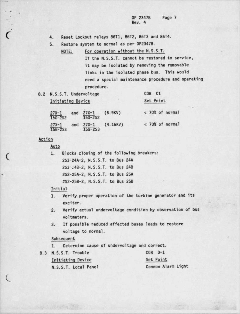
4. Reset Lockout relays 86T1, 86T2, 86T3 and 86T4.
5. Restore system to normal as per OP23478.
NOTE: For operation without the N.S.S.T. .
If the N.S.S.T. cannot be restored to service,
it may be isolated by removing the removablelinks in the isolated phase bus. This wouldneed a special maintenance procedure and operating
procedure.
8.2 N.S.S.T. Undervoltage C08 C1'Initiating Device Set Point
- .
2_7X-1 and 27X-1 (6.9KV) < 70% of normal15G-252 15G-2S2
27X-1 and' 27X-1 (4.16KV) < 70% of normal15G-2S3 15G-2S3
ActionAuto
1. Blocks closing of the following breakers:C
.
2S3-24A-2, N.S.S.T. to Bus 24A253-24B-2, N.S.S.T. to Bus 24B2S2-25A-2, N.S.S.T. to Bus 25A+
2S2-25B-2, N.S.S.T. to Bus 25B -
Initial'
1. Verify proper operation of the turbine generator and itsexciter. -
_ ,
2. Verify actual undervoltage condition by observation of bus'
' voltmeters.,
- 3. If possible reduced affected buses loads to restorevoltage to normal.
'Subsequent
- 1. Determine cause of undervoltage and correct.,
8.3 N.S.S.T. Trouble C08 0-1
Initiatina Device Set Point
N.S.S.T. Local Panel Common Alarm Light
-
-..-
.b e-
g .,, g- - - - - ,, .g
__ _ ..__ __ _ _ __ . __ _ _ _ . _ _ _ _
- . . .,
'
DP 23478 Pago 8*
.
", Rev. 4'-
'
. . 2. ,.
b Action-
Auto
- 1. None. .
Initial j
| 1. Monitor main control board indication of voltage, current, j,
! KW, etc. , or other alarms to determine if a fault exists .
.on-the N.S.S.T. j'
2. Monitor N.S.S.T. Lemperature and other parameters on the
plant Data Logger.'
3. Dispatch an operator to the N.S.S.T. local common, alarm.
i~ light panel to determine what the alarm is. -
']Subsequent .
1. , Refer to. Subsequent action under individual N.S.S.T.I alarms.
8.3.1 N.S.S.T. cooler Power Auto Transfer Local Panel'
2
; Initiating Device Set Point: Transfer Device Loss of selected power supply; . { -
ActionAuto
,
1. Automatic transfer of power to the alternate source... .,
Initial
1. Reset local alarm to enable future N.S.S.T. alarms toannunciate main control board "N.S.S.T. Trouble".. /~ _v_---qs
" -'
.
'
~1 N' d2. Check closed breakers 8C-2, 8C-3 on local panel. <
4
3. Check for blown fuses, FU-1, on local panel. -
!. 4. Check closed power supply breakers on MCC22-2A and MCC22-1DA.
5. Insure fans and pumps are running as applicable.Subsequent .
1. If cause of trouble cannot be ietermined, notify Maintenance. .
Department.
; 8.3.2 N.S.S.T.
High Combustible Gas
Initiating Device Set Point.
2n..-.
'. !. p. ; ggfs " . i w -j* .42" 44
f'
.tyi. -.s.*,uo ./ ( p - : my
, _ . . . . - . - . . - . . . . . _ _ . . . _ _ _ . _ _ . _ . . _ . _ _ . _ , _ . _ . _ . _ . , . . . _ _ _ . _ _ . . _ , . . . , . , . _ . . _ _ _ . . - . _ _ . . _ _ .__ . . _ _ _ _ , _ , . _ _ . . _ _ .

,.
' . * ~,
'
Rev,. 4
.
OP 2347B Pagn 9'
,
' '
.
Fault Gas Monitor 1%
Action-Auto -
-1. None.'
Initial
1. . Reset local alarm to enable future alarms to annunciateMain Control Board "N.S.S.T. Trouble".
' 2. ~ Observe local fault gas monitor indication.3. Notify Control Room of indication.
A. * Classification of Total Combustible Gas Reading
TCG Reading % Course of Action -
0.5 No Action0 -
0.5 - 1 Caution: Close'
surveillance for upward
Trends
5 Investigate cause1 -
immediately
i (.- 5 Remove transformer from~
-
service until cause is4
- located and remedied *
; Subsequent,
1. High fault, gas monitor reading could indicate an internal -
.
fault, notify CONVEX of indication.I 2. Proceed as directed by CONVEX. -
_ _ . __
8.3.3 N.S.S.T. Hi-Lo Tank Pressure~ '
Indicating Device Set PointPressure Sensor Hi 3.0 psigPressure Sensor to .25 psig
Action .
Auto
1. None.~
Initial
1. Reset, local alarm to enable future alarms to annunciatemain control board "N.S.S.T. Trouble".
-{
- .-
'
g,k k~ ns" ? . r, . - fjy] ' ,.: .+' 'a-' *. g_c i
. - _ - - .. - _ - . . ._
.
.. ,
OP 2347B P ga 10*
.'
Rev. 4*
,
2. Observe local gas regulator pressure, tank l'iquid leveland winding temp.
3. Notify Control Room. .
: Subsequent
: 1. Hi Tank pressure could result from a failed nitrogenregulator or an internal / external fault (normal range is1.0 psig to 1.5 psig) or from increasing transformer load.
! 2. If there is an internal or external fault, notify CONVEX
! and proceed as directed.
3. 'If N2 regulator has failed, replace same as per General'
Electric instruction manual for the N.S.S.T. after notifying
CONVEX of,the malfunction.*
4. If tank pressure is low, have Electrical Maintenance carryout the required adjustment. If regulator has failed,
[ repeat subsequent action step (3). If N2 bottle isexhausted, replace same..
.
8.3.4 N.S.S.T. Liquid Temp' ' N.S.S.T. Winding Temp (Y) Local Panel
-
N.S.S.T. winding Temp (X)- Initiating Device Set Point
1. Oil Temp. Detector 90'C
2. Winding Temp. Detectors 105*C,
,
Action_
N'Auto*.
'
1. None.
Initial
1. Reset local alarm to enable future alarms to annunciateMain Control Board "N.S.S.T. Trouble". .
.
Check local temperature indicators.2.
3. Check cooling fans and oil pumps operating select " hand"operation for cooling fans and oil pumps at local panel,if necessary.
4. Check closed cooling fan and oil pumps CKT Bkrs. at local
b panel 8C-4, 8C-5, 8C-6, 8C-7. .
.
1
' ;t~
- .n' . @

. - -._ . _ _ _ _ _ . . -
4 ~ e .
'
OP 23478 Psga 11~
.,
J Rev. 4-
,' # :;.
Subsequent
1. If temperature control cannot be regained, notify CONVEX.2. If temperature exceeds 105'C on NSST 6.9 KV windings, .
monitor temperature. If temperature exceeds 115*C,;
transfer one 6.9 KV bus to the reserve station servicetransformer.
8.3.5 N.S.S.T. Pressure Relief'
Indicating Device Set PointPressure Relief Value (red light) > Spsi
Action.'
Auto'' -
p
1. Relieve overpressure condition in the tank.
| Initial
1. Reset local alarm to enable future alarms to annunciatei Main Control Board "N.S.S.T. Trouble".
2. ~ Observe which relief value has lifted, verify overpressurecondition has been corrected and check that relief valve
i( has reset.-
| 3. Notify Control Room.'
Subsequent
1. Follow applicable portions of 09 Procedure, Section .
8.3.3.1 and 8.3.3.2 initial and subsequent action as tocauses,and corrective action for tank overpressure.
.
8.3.6 .N.S.S.T. Liquid Level Local Panel-
# ,. m,
'
. - Initiating Device Set Point i4,
,.
- Liquid level gauge.
Low Mark
ActionAuto
L 1. None. .
| Initial
|'
1. Reset local alarm to enable future alarms to annunciateMain Control Board "N.S.S.T. Trouble".
2. Check local level indications.3. Check N.S.S.T. for oil leaks.
|
s .
.w'y
~
_ w
moe, ,.s. .,
,
. - . . -. _ . . . _ . . . . . _ _ . _ . _ _ _ . . . _ . _ _ , _ _ _ , . _ _ _ _ . _ _ . _ _ _ _ . . _ _ _ _ . . _ _ . . _ _ . , _ _ ___ , _ _ _ , , _ _ . . , - .

_ _ _ ___ __ . - _ . . _ __ _ . - . _ _
. .,
OP 23478 Page 12*
,*
Rev. 4+
9
'
Subsequent*
1. ' _On a major oil leak where the transformer windings will be'
uncovered, notify CONVEX and proceed to remove the N.S.S.T. .
from service.2. On a minor oil leak, notify CONVEX and closely observe oil
level until corrective action has been taken. j.
8.3.7 N.S.S.T. loss of liquid flow Local Panel
Initiatina Device Set Point.
.
Liquid flow gauge Less than 90% normal
Action (:Auto |
* -
1. None.
Initial,
1. Reset local alarm to enable future alarm to annunciate. Main Control Board "N.S.S.T. Trouble".
i
! 2. Check oil pumps operating.
3. Check breakers 8C-6, 8C-7 on local panel closed.
b 4. Check oil pump overloads reset.4
| 5. Check oil level.l Subsequent
1. Place oil pumps in manual, if oil pumps will not run or,
L flow alarm will' not clear, notify Maintenance Department.I 2. Notify CONVEX.
8.3.8 N.S.S.T. Loss of Control Power Local Panel. _
eb-, . * ,| *,n
Initiating Device Set Point R' -w
Control Power Undervoltage Less than 70% normal '
ActionAuto
1. Loss of N.S.S.T. Cooling fans and oil pumps. . .
2. Loss of fault gas monitor.i 3. Loss of local panel heaters, lights and convenience
~
outlets.Initial
1. Reset local alarm to enable future alarms to annunciate
h. Main Control Board "N.S.S.T. Trouble".
:
i
'
. ,
3 ,yN g., '' h ,' M , b- y , , J34 j'.F, - '
_
- _ _ . _
. . . .
b =,.
'
OP 2347B Pcgn 13. ,
* Rev. 4,
* . ,
2. Check closed circuit breakers 8C-1, 8C-2 and 8C-3 on the
local panel.3. Check for blown fuses, FU-1, on local panel. -
4. Check closed power supply breakers on MCC22-2A and MCC22-IDA.
Subsequent -,
1. If control power cannot be restored, notify CONVEX and-
proceed as directed to remove the N.S.S.T. from service.*
8.3.9 N.S.S.T. Low Gas Cylinder Pressure Local PanelInitiating Device Set Point -
Pressure Switch 63GC 200psig |*-Action ,
Auto
1. None.
Initial
1. Reset local alar = to enable future alarms to annunciate;
Main Control Board "N.S.S.T. Trouble".2. Verify N.S.S.T. tank pressure as normal.
( 3. Verify low pressure condition of the N2 gas cylinder.-
Subsequent
1. Notify Control Room of indications.2. Replace the spent N2 gas cylinder with a full one.3. Check system for leaks.
.
. ~ * ,
_ q, . ._
| RB:j1ci
i
!i
,a
.
!
|
(i:-
!|
'.d;D-f -am J'. ;j;, ' ' J. d
. _ _ _ . . _ _ , _ . . . _ _ _ _ . _ . . _ _ _ _ . . - . _ . . _ , _ _ . . _ . __