
Change 2,Rev 4 to Procedure OP2347B, "Normal Station Svc ...
Upload
independentCategory
view
0download
0
A B B R e v i e w 6 / 1 9 9 8 21
he appearance on the market of con-
tinuously controllable semiconductor de-
vices capable of handling high powers has
made voltage source converters with
highly dynamic properties feasible far
into the tens of MVA. ABB’s newly intro-
duced SVC Light concept, which com-
bines VSC and IGBT (Insulated Gate Bipo-
lar Transistor) technology, offers com-
pletely new options for power quality con-
trol in areas previously closed to it or which
have been only partly manageable, eg the
mitigation of voltage flicker caused by
heavy industrial loads fed from weak dis-
tribution grids.
Power quality
The risk to the utility
During the 1990s the issue of flicker has
grown dramatically in importance, es-
pecially in countries in which the electrical
power market has been deregulated.
Power quality has become a strength in
the marketplace. Utilities who ignore their
customers, whatever their size, risk losing
them to competitors. This has set the
stage for solutions that, by mitigating flick-
er, give utilities a competitive edge.
The steelworks’ point of view
The short-circuit power of the electricity
network and the available power often
place restrictions on the maximum pro-
duction that can be planned for new steel-
works. The small, additional investment in
SVC Light is quickly paid back by the in-
crease in productivity that it allows. SVC
Light not only stabilizes the voltage and
ensures sufficient power, but also, by miti-
gating flicker, eliminates the risk of flicker
restrictions dictating the size of the in-
stalled electric arc furnace. With SVC
Light, neither flicker requirements nor high
electrical power demand need to be limit-
ing factors when planning new steel plant
projects.
The first SVC Light project, at the Ud-
deholm Tooling steel plant in Hagfors,
Sweden, is running at full speed. Energiz-
ation is planned at the end of 1998 and the
official hand-over to the customer is
scheduled for January 1999.
Disturbances travel far
and wide
To the steelmaker using scrap as his basic
raw material, the electric arc furnace (EAF)
is both an essential and efficient piece
of equipment. The grid owner and the
electricity supplier, however, see the EAF
user not only as a customer, but also, in
the worst case, as a contributor of pollu-
tion to the grid. The EAF may be the
source of massive distortion in the form
of voltage fluctuations, harmonics and
phase unsymmetry. Also, the grid may
have to carry reactive power during oper-
ation of the EAF, causing transmission
losses and impeding the flow of useful,
active power.
The same, or similar, can be said about
other kinds of heavy industrial loads (eg,
rolling mills, large mine hoists, etc), all of
which take their power from distribution
grids.
If they are not properly contained, dis-
turbances emanating from any one indus-
trial load will spread via the grid to neigh-
bouring facilities .
Fortunately, there are ways of dealing
with the problem of poor or insufficient
power quality in grids. One obvious one is
to reinforce the power grid by building new
lines, installing new and more powerful
transformers, or moving the point of com-
mon coupling to a higher voltage level.
Such measures, however, are expensive
and time-consuming, if they are permitted
at all.
1
SVC Light –a powerful toolfor power qualityimprovement
Bo Bijlenga
Rolf Grünbaum
Thomas Johansson
ABB Power Systems AB
ABB has developed and introduced a new technology called SVC Light
which brings together the VSC (Voltage Source Converter) and IGBT
(Insulated Gate Bipolar Transistor) to create a tool offering unique
possibilities for power quality improvement in the high power range. The
new technology is being installed at a steel plant in Sweden, where it
will mitigate flicker caused by the operation of a large electric arc
furnace.
T
P O W E R Q U A L I T Y

22 A B B R e v i e w 6 / 1 9 9 8
A simple, straightforward and cost-ef-
fective way to improve power quality is to
install dedicated equipment in the immedi-
ate vicinity of the source(s) of disturbance.
SVC Light (SVC stands for Static Var Com-
pensator) was developed especially for
this purpose.
As an additional benefit, SVC Light im-
proves the process economics, making
the investment more attractive to the
owner of the installation(s) causing the
disturbance and actually making the
investment profitable after a limited period
of time.
Voltage flicker
An electric arc furnace is a heavy con-
sumer of not only active but also reactive
power. Also, the physical process taking
place in the furnace (electric melting) is er-
ratic by nature, involving one or several
electrodes striking electric arcs between
the furnace and the scrap. Consequently,
the consumption of reactive power fluctu-
ates especially strongly .
Because of this, the voltage drop
caused by reactive power flowing through
circuit reactances in the electrodes, elec-
trode arms and furnace transformer also
fluctuates erratically. The result is voltage
flicker, evidence of which can be seen most
clearly in the flickering light of incandescent
lamps fed from the polluted grid.
Spectral analysis confirms that lamp
flicker caused by EAF action is severe
around frequencies to which the human
eye is particularly sensitive, ie below
20 Hz. As it is a very annoying sensation,
flicker quickly becomes a cause for com-
plaint.
The International Union of Electroheat
(IUE) and the IEC have cooperated in de-
fining a quantity, Pst, for expressing flicker
severity. According to this definition,
Pst = 1 means that in a group of people
exposed to light flicker, half of them will
notice it.
2
SVC Light
SVC Light is a flicker mitigating device that
attacks the root of the problem, ie the er-
ratic flow of reactive power through the
supply grid to the furnace. It does this by
measuring the reactive power consump-
tion and generating a corresponding
amount for injection into the system,
thereby reducing the net reactive power
flow to an absolute minimum. As an im-
mediate consequence, voltage flicker is
also minimized.
Important added benefits are a high
and constant power factor, regardless of
the load fluctuations over furnace cycles,
as well as a high and stable bus rms volt-
age. These benefits translate into im-
proved furnace productivity as well as
lower operating costs due to lower spe-
cific electrode and energy consumption
and reduced refractory wear.
To balance the rapidly fluctuating con-
sumption of reactive power, an equally
rapid compensating device is required.
G GGeneratingsource
Main transmission grid
Regional grid
Local grid
Heavy industry
Urban area
Rural system
How disturbances emanating from an industrial load spread via the grid to other facilities 1
P O W E R Q U A L I T Y

A B B R e v i e w 6 / 1 9 9 8 23
This is achieved with state-of-the-art
power electronics based on IGBT technol-
ogy. With the advent of continuously con-
trollable semiconductor devices capable
of handling high powers, voltage source
converters with highly dynamic properties
have become feasible far into the tens of
MVA.
The function of the VSC in this con-
text is to provide a fully controllable voltage
source matching the bus voltage in phase
and frequency, with an amplitude which
can be continuously and rapidly controlled.
A VSC with such characteristics can be
used for reactive power control .
By controlling the VSC voltage in re-
lation to the bus voltage the VSC acts as a
generator or absorber of reactive power,
depending on the relationship between the
voltages. A range-offsetting capacitor bank
is connected in parallel with this controlled
reactive power branch to make the overall
control range of SVC Light capacitive.
The controllability of IGBTs also facili-
tates series connection of devices with
safeguarded voltage sharing across each
IGBT. This enables SVC Light to be con-
3
nected directly to voltages in the range of
tens of kilovolts, eliminating the need to
connect converters in parallel in order to
achieve the power ratings needed for arc
furnace compensation (typically tens of
MVA).
Voltage source converters
The input of the voltage source converter
is connected to a capacitor, which acts as
a DC voltage source. The converter pro-
duces a variable AC voltage at its output
by connecting the positive pole or the
negative pole of the capacitor directly to
any of the converter outputs. In converters
that utilize pulse width modulation (PWM)
the input DC voltage is normally kept con-
stant. The output voltage can be, for
example, a sinusoidal AC voltage, the am-
plitude, frequency and phase of which can
be controlled by changing the switching
pattern.
Voltage source converters that utilize
PWM are widely used today, even domi-
nating in applications such as speed and
torque control of AC motors.
In electrical transmission and distribu-
tion applications, voltage source con-
verters featuring PWM have many uses,
for example as rectifiers and inverters
in HVDC systems, as reactive power
compensators, as power conditioners
and for connecting different kinds of ener-
gy sources or loads to the electric net-
work.
VSC for reactive power
compensation
If the output of a VSC is connected to the
AC system by means of a small reactor,
the VSC can be said to resemble a syn-
chronous generator without any rotating
mass. By controlling the output voltage
of the VSC in such a way that it has
the same phase angle as the line voltage,
the converter can either consume or
generate reactive power. This is done by
80
MVAr
60
40
20
00 2000 4000 6000 8000s
t
P
Reactive power consumption of an electric arc furnace (EAF)
P Calculated EAF reactive power t Time
2
Voltage source converter (VSC) used for reactive power control
U2 > U1: capacitive currentU2 < U1: inductive current
I CurrentU1 Bus voltageU2 VSC voltageUX Reactor voltageX Reactance
3
VSC
U 1
U X U X
U 1 U 2 U 1 U 2
U 2
I
X
I
I
U 2 > U 1 U 2 < U 1
P O W E R Q U A L I T Y

24 A B B R e v i e w 6 / 1 9 9 8
controlling the amplitude of the output
voltage . If the output voltage is higher
than the line voltage, the converter will
generate reactive power and act as a
shunt capacitor. If the output voltage is
lower than the line voltage, the converter
will consume reactive power and act as a
shunt reactor. The reactive power supplied
to the network can be controlled very fast;
all that is required is a slight change in the
switching pattern in the converter. The
response time is limited mainly by the
switching frequency and the size of the
reactor.
In SVC Light the VSC uses a switching
frequency greater than 1 kHz. The AC volt-
age across the reactor at full reactive
power is only a small fraction of the AC
voltage, being typically 15 %. SVC Light
therefore comes close to being the ideal
tool for fast reactive power compensation.
This raises the question of why voltage
source converters are not more widely
used today for static compensation.
To answer this question it has to be
considered that the VSC utilizes turn-off
type power devices, such as GTOs (Gate
Turn Off Thyristors) or IGBTs, and that to
connect the VSC to the 10–36 kV distribu-
tion system direct, eg without using an
3
intermediate transformer, a high-voltage
converter is needed. This calls for series-
connection of the power devices. Also, a
high switching frequency is required to
keep the harmonics supplied to the net-
work small and ensure fast step response
by the compensator. The combination of
series-connected turn-off type power
devices and a high switching frequency
creates several technical challenges.
Intensive R&D at ABB Power Systems has
brought forth solutions that effectively ad-
dress these issues.
The IGBT
The most suitable power device for SVC
Light was found to be the IGBT because its
short turn-on/turn-off delay times make it
relatively easy to connect in series. Also,
since it features low switching losses it can
be used at high switching frequencies. An-
other advantage is that no di/dt limiting
reactors or snubber capacitors are
needed. Instead, di/dt and du/dt control
can be performed by gate control. Now-
adays, several manufacturers offer devices
combining high power capability and high
reliability – features which make the device
also suitable for high-power converters.
The IGBT is a bipolar transistor with an
MOS (Metal Oxide Semiconductor) gate
to which either a positive or negative volt-
age is applied for control purposes. Since
only a very low power is needed to control
the IGBT, the power for gate control can
be taken from the main circuit. This is high-
ly advantageous in high-voltage con-
verters, in which many devices are con-
nected in series.
Presspack IGBTs are used in SVC
Light. The press-pack IGBT is a new
device, developed to meet the very high
demands made on reliability and now
being used in the new generations of high-
speed trains, where the combination of
high power and high reliability is very
important.
A presspack IGBT is packaged in a
housing almost like a conventional high-
power thyristor. Inside it, IGBT chips and
antiparallel diode chips are connected in
parallel, with pressure contacts normally
providing the electrical contact to the out-
side. This type of device features a short-
circuit failure mode, which is very favour-
able in a converter with series-connected
devices. Thus, a device that fails will act as
a short circuit. Since redundant devices
are a standard feature of SVC Light, failure
of one device will have no effect on the
converter, which can continue operating at
full power. The failure is monitored and the
device can be replaced at a time which will
cause minimum disturbance to the pro-
cess.
The IGBTs in the Hagfors installation in
Sweden are rated at 2.5 kV for a nominal
current of 1,800 A. The turn-off capability
of the device is 3.6 kA in normal operation.
In the event of a short circuit the device
itself will limit the current to less than
10 kA. In this case, the short circuit is
detected by a protection system and the
device can be safely turned off by apply-
ing a so-called ’soft turn-off’ signal to the
gate.
Powersupply
Gateunit
Powersupply
Gateunit
IGBT valvecontrol unit
Fiber-opticlinks
Fiber-opticlinks
Fiber-opticlinks
Maincontroller
Powersupply
Gateunit
Voltagedivider
Voltagedivider
Voltagedivider
The IGBT valve with simultaneously switched, series-connected IGBTs 4
P O W E R Q U A L I T Y
A B B R e v i e w 6 / 1 9 9 8 25
Series connection of IGBTs
When connecting IGBTs in series it is im-
portant for the voltage to be properly di-
vided. Simultaneous turn-on/turn-off of
the series-connected devices is essential.
In SVC Light, the turn-off and turn-on sig-
nals are distributed to the individual IGBTs
by a high-bandwidth, fiber-optic system.
The IGBTs are also equipped with a
special type of gate unit which turns the
IGBTs on and off with a short delay time
and at a controlled du/dt. Turn-off of an
IGBT valve or diode valve is followed by a
small voltage difference between the dif-
ferent IGBT positions. This difference is
controlled by proper design of the resistive
and capacitive voltage dividers .
In addition, every IGBT has its own
overvoltage monitoring system for the de-
tection of abnormal IGBT behaviour.
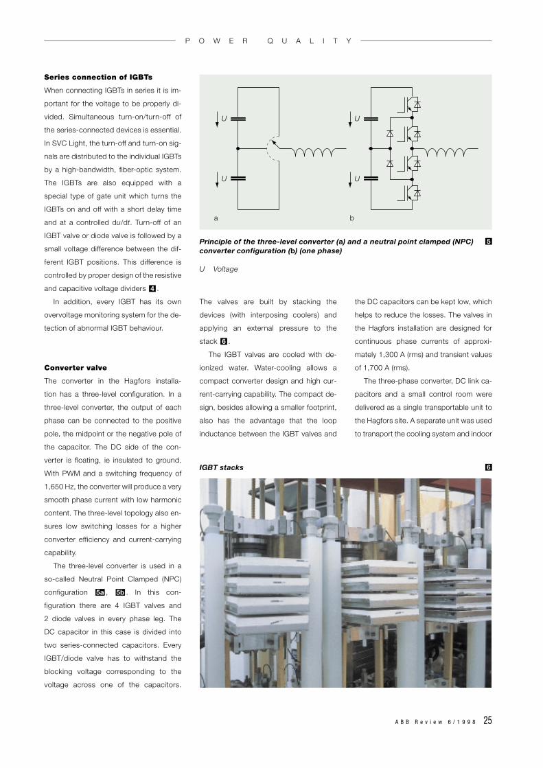
Converter valve
The converter in the Hagfors installa-
tion has a three-level configuration. In a
three-level converter, the output of each
phase can be connected to the positive
pole, the midpoint or the negative pole of
the capacitor. The DC side of the con-
verter is floating, ie insulated to ground.
With PWM and a switching frequency of
1,650 Hz, the converter will produce a very
smooth phase current with low harmonic
content. The three-level topology also en-
sures low switching losses for a higher
converter efficiency and current-carrying
capability.
The three-level converter is used in a
so-called Neutral Point Clamped (NPC)
configuration , . In this con-
figuration there are 4 IGBT valves and
2 diode valves in every phase leg. The
DC capacitor in this case is divided into
two series-connected capacitors. Every
IGBT/diode valve has to withstand the
blocking voltage corresponding to the
voltage across one of the capacitors.
5b5a
4
The valves are built by stacking the
devices (with interposing coolers) and
applying an external pressure to the
stack .
The IGBT valves are cooled with de-
ionized water. Water-cooling allows a
compact converter design and high cur-
rent-carrying capability. The compact de-
sign, besides allowing a smaller footprint,
also has the advantage that the loop
inductance between the IGBT valves and
6
the DC capacitors can be kept low, which
helps to reduce the losses. The valves in
the Hagfors installation are designed for
continuous phase currents of approxi-
mately 1,300 A (rms) and transient values
of 1,700 A (rms).
The three-phase converter, DC link ca-
pacitors and a small control room were
delivered as a single transportable unit to
the Hagfors site. A separate unit was used
to transport the cooling system and indoor
U U
U U
a b
Principle of the three-level converter (a) and a neutral point clamped (NPC)converter configuration (b) (one phase)
U Voltage
5
IGBT stacks 6
P O W E R Q U A L I T Y
26 A B B R e v i e w 6 / 1 9 9 8
switchgear. The Hagfors converter is con-
nected to a 10.5 kV AC system.
ABB Power Systems can also deliver
SVC Light for direct connection to higher
voltages, ie up to 36 kV AC.
Flicker mitigation
ABB Power Systems’ broad experience in
the field of flicker mitigation has shown
that successful flicker damping is highly
dependent not only on the switching fre-
quency but also on the time delay be-
tween the sampling of the measured val-
ues and the next switching instant, and
ultimately on the implemented control
algorithms.
Computer studies and field measure-
ments of EAF reactive power compen-
sation give a good idea of how flicker
compensation can be optimized. To fully
utilize the developed control strategies a
reactive power compensator is required
that can be controlled at least 15 times
faster than existing technology (100 Hz).
This kind of performance can only be
achieved with VSC technology based on
IGBTs.
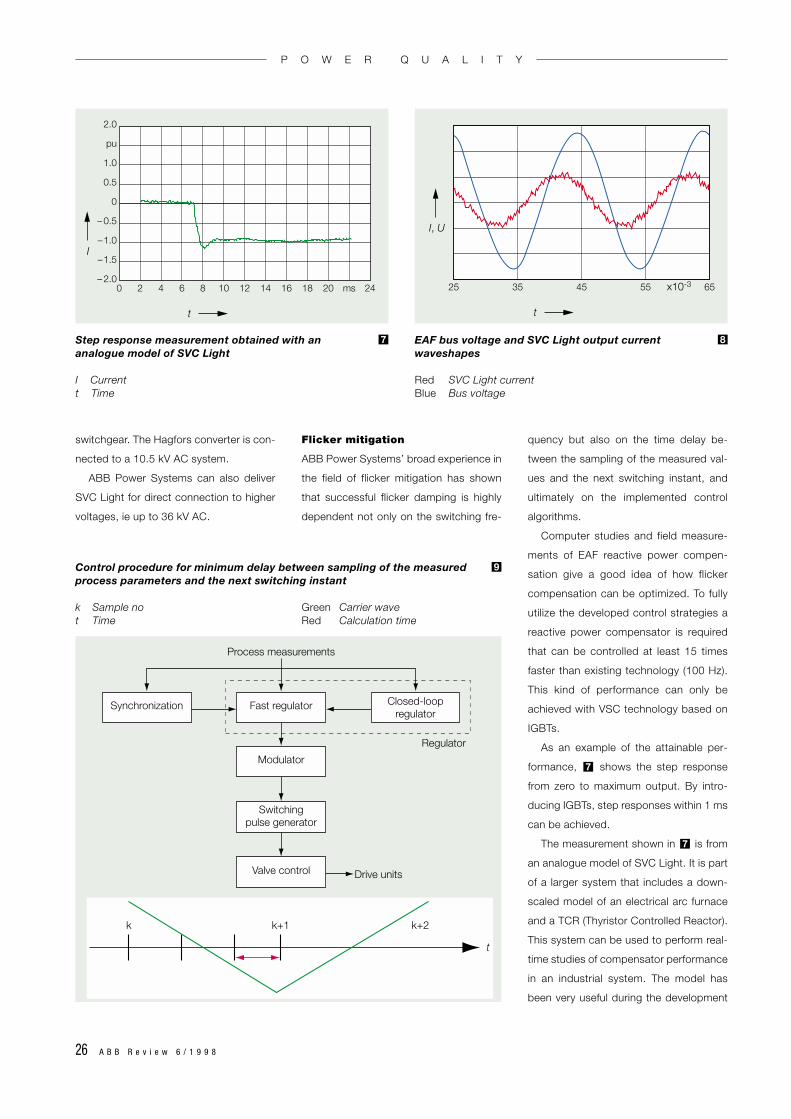
As an example of the attainable per-
formance, shows the step response
from zero to maximum output. By intro-
ducing IGBTs, step responses within 1 ms
can be achieved.
The measurement shown in is from
an analogue model of SVC Light. It is part
of a larger system that includes a down-
scaled model of an electrical arc furnace
and a TCR (Thyristor Controlled Reactor).
This system can be used to perform real-
time studies of compensator performance
in an industrial system. The model has
been very useful during the development
7
7
0
2.0
pu
1.0
0.5
0
– 0.5
–1.0
–1.5
– 2.02 4 6 8 10 12 14 16 18 20 ms 24
t
I
25 35 45 55 x10-3 65
t
I, U
Step response measurement obtained with an analogue model of SVC Light
I Currentt Time
7 EAF bus voltage and SVC Light output currentwaveshapes
Red SVC Light currentBlue Bus voltage
8
Synchronization Fast regulator
Modulator
Switchingpulse generator
Valve control
Closed-loopregulator
Regulator
Process measurements
Drive units
k k+1 k+2
t
Control procedure for minimum delay between sampling of the measuredprocess parameters and the next switching instant
k Sample no Green Carrier wavet Time Red Calculation time
9
P O W E R Q U A L I T Y

A B B R e v i e w 6 / 1 9 9 8 27
of both software and hardware for flicker
compensators.
PWM enables VSC technology to be
fully utilized. While the switching frequen-
cy has to be chosen high enough for flick-
er mitigation purposes, consideration also
has to be given to losses and harmonic
requirements. For the Hagfors installation
a pulse number of 33, corresponding to a
switching frequency of 1,650 Hz, was
chosen. The time between consecutive
switching is therefore only 303 µs. In prac-
tice, the result is a compensator capable
of continuous control of the reactive
power. The impact of the valve switching
is reduced to negligible kinks in the com-
pensator output current .
Another prerequisite for optimum flick-
er mitigation is a minimum delay between
sampling of the measured process pa-
rameters and the next switching instant.
One standard control procedure is to
synchronize the process parameter
measurements with the main circuit
switching instants, which in this case
would result in a time delay of 303 µs.
However, studies have shown that a
further reduction would have additional
benefits for flicker mitigation. The goal has
therefore been to perform the calculations
for the flicker algorithm (fast regulator) as
8
close as possible to the switching oper-
ation, ie basing them on values measured
as late as possible. shows how the pro-
cess measurements are carried out as
close as possible to the switching oper-
ation in order to minimize delay to the ac-
tual calculation time.
9
MACH2 control and
protection system
To ensure fast and extensive data pro-
cessing, ABB Power Systems developed
the MACH2 control and protection
system. It is based on industrial standard
PC hardware (with Windows NT) in order
to facilitate an open system which can be
easily integrated in existing systems at the
Valve control
Main computer
I / O rackU
PCI
CP / FP
TDM CAN
PS 801C&P( fast )
PS 820SUP
CPUPent Pro
C&P( slow )
LAN
MACH2 control and protection system for SVC Light
CAN Controller area networkCPU Central processing unitCP/FP Control pulses/firing pulsesLAN Local area networkPCI Peripheral component interconnect busSUP Supervision boardTDM Time division multiplexed bus
10
P O W E R Q U A L I T Y
Overview of the Hagfors plant (left) and a VSC valve detail (right) – two of the graphics on display at the operator workstation
11

28 A B B R e v i e w 6 / 1 9 9 8
steelworks and externally accessed di-
rectly by RAS (Remote Access Services).
The strategy of basing the control and
protection system on open interfaces
ensures that advantage can also be taken
of future improvements in the fast-chang-
ing field of electronics. Basically the system
consists of three units: the main computer,
the I/O rack, and the valve control unit.
Communication between the units takes
place over standard industrial buses .
Operation of SVC Light
The system is operated from an operator
workstation (OWS), which can be a stand-
ard PC. The man-machine interface (MMI)
is the world’s most used graphic control
package for Windows NT – InTouch. In-
Touch software is highly flexible, even of-
fering a full Chinese version, and allows
specially customized MMIs to be easily
designed .
Start and stop sequences are initiated
at the OWS. SVC Light currents and volt-
11
10
33 MVA 33 MVA
132 kV PCC
=~
EAF31.5 / 37.8 MVA
LF6 / 7.7 MVA
Existing14 MVAr
+/–22 MVAr
3rd8 MVAr
10.5 kV
SVC Light
Single-line diagram of the Hagfors furnaces and the installed SVC Light configuration
EAF Electric arc furnaceLF Ladle furnacePCC Point of common coupling
12
–
~
–
–
2
1
4
3
8
5
6
7
12
109
m+
–
m+
–
m+
–
~
~
11
M
Main circuit diagram of Hagfors SVC Light
1 Incoming feeders2 EAF bus3 Load (furnaces)4 Main circuit-breaker5 Harmonic filter6 SVC Light container7 Capacitors8 DC bus9 Valves
10 Reactors11 Bypass switch12 Pre-insertion resistors
m DC side midpoint
13
P O W E R Q U A L I T Y
A B B R e v i e w 6 / 1 9 9 8 29
ages, event and alarm lists, and the
statuses of all the equipment are dis-
played. InTouch uses DDE (Dynamic Data
Exchange) to collect data from the control
and protection system. This enables data
to be collected by any computer on the
local area network, which is set up as a
DDE server. InTouch also has its own
sequence of events recorder, which time-
tags DDE variables as defined by the user.
Powerful
single-board computer
In addition to the standard equipment,
specially designed hardware has been
developed by ABB Power Systems to en-
sure the high performance required. The
fast regulator is implemented, together
with other functions, on a single-board
computer (PS801) containing a cluster of
six very powerful digital signal processors
(DSPs) from Analog Devices, which to-
gether provide a calculation capacity of
more than 700 Mflops (million floating
point operations per second). The activ-
ities of these DSPs are coordinated by an
Intel general-purpose processor on the
same board. Also on this board is the logic
for the control pulse generation, which is
implemented in one large FPGA (Field Pro-
grammable Gate Array) circuit.
The programs for the processors and
DSPs are stored in flash PROMs, which
are programmed and erased on the board.
Changes to the software can therefore be
made without having to remove the
boards from their position.
In addition to the supervisory tasks as-
signed to each part of the system, all of
the hardware, software and communi-
cations are monitored continuously by a
separate supervision board, PS820. This
combination of distributed supervision and
central supervision board guarantees the
high reliability required for high-power
applications.
Interface to the process and
valve control
An I/O rack with digital and analogue I/Os
can also be connected. This processes
and summates the collected data and
afterwards sends them to the main com-
puter via data buses. Each analogue input
board has a DSP, which can be used for
data preprocessing (eg, conversion from
phase to vector representation and filter-
ing) to minimize the amount of data
that has to be communicated to the regu-
lators.
The PS801 board generates control
pulses for the IGBT valve, which the valve
control unit (VCU) converts into light sig-
nals for transmission to the gate units.
Besides receiving IGBT control signals
from the VCU, the gate units also send
status information on the different IGBT
P O W E R Q U A L I T Y
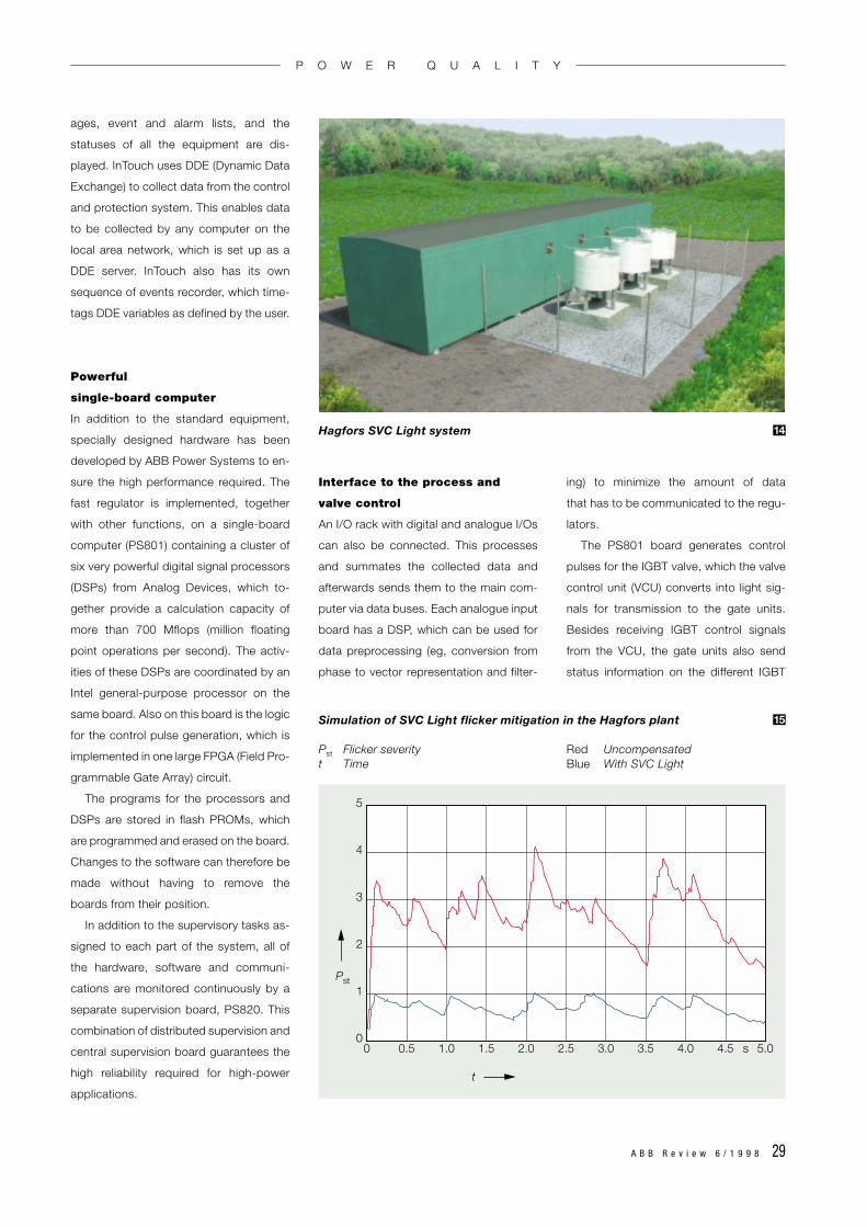
Hagfors SVC Light system 14
5
4
3
2
1
00 0.5 1.0 1.5 2.0 2.5 3.0 3.5 4.0 4.5 5.0s
t
Pst
Simulation of SVC Light flicker mitigation in the Hagfors plant
Pst Flicker severity Red Uncompensatedt Time Blue With SVC Light
15

30 A B B R e v i e w 6 / 1 9 9 8
positions to the valve monitoring system.
The VCU is also responsible for the fast
valve protection.
Communication between the systems
is via three different buses:
• PCI (Peripheral Component Intercon-
nect) bus, a standardized high-per-
formance, parallel back-plane bus
(32-bit version) with a transfer capabil-
ity of 133 Mbyte/s.
• CAN (Controller Area Network, ISO
11898) buses, which handle digital
orders, eg to breakers, and indications.
• TDM (Time Division Multiplexed) buses,
with high-speed synchronous serial
channels for the transfer of numerical
data between the I/O rack and the main
computer.
Uddeholm Tooling – a pioneer
At Uddeholm Tooling at Hagfors in central
Sweden, the metallurgical process is
based on scrap melting in an electric arc
furnace and subsequent refining in a
ladle furnace. The arc furnace is rated at
31.5 MVA with a 20% temporary overload
capability, whereas the ladle furnace is
rated at 6 MVA plus 30% overload. Both
furnaces are fed from a 132-kV grid via an
intermediate voltage of 10.5 kV .
The grid is relatively weak, with a fault
level at the point of common coupling
(PCC) of about 1,000 MVA. It is obvious
12
that this is too low to allow operation of
the two furnaces and at the same time
ensure an acceptable power quality for the
grid.
A qualitative idea of the amount of
flicker that can be expected with this
combination of load size and grid fault
level can be obtained from a simple ex-
pression:
Pst ≈ 75SSCEAF
SSCN
where Pst is the flicker severity, SSCEAF the
short-circuit power of the electric arc
furnace and SSCN the fault level of the grid
at the PCC. A measure of the worst-case
flicker is obtained by inserting in the
formula double the power rating of the
EAF, ie 63 MVA, and the lowest value for
SSCN. This gives the value of 4.5 for Pst,
corresponding to severe flicker and calling
for measures capable of effective miti-
gation.
The SVC Light installation , has a
reactive power rating of 0–44 MVAr. This
dynamic range, which is continuously vari-
able, is obtained with a 22-MVA VSC in
parallel with two harmonic filters, one rated
at 14 MVAr and already existing in the
plant, and one, rated at 8 MVAr, installed as
part of the SVC Light project. The VSC is
connected directly, via its phase reactors,
to the furnace bus voltage of 10.5 kV. This
is made possible by connecting IGBTs in
1413
series in order to attain the required voltage
rating of the equipment.
To prevent the DC capacitors from
being charged to an inadmissibly high
level through the antiparallel diodes of the
three-level bridge, inrush current limiting
resistors are included in the starting se-
quence of SVC Light, after which the resis-
tors are bypassed.
Powerful flicker mitigation
The maximum residual flicker level tar-
geted for the 132-kV PCC with SVC
Light in operation is Pst(95) = 1. This level
is based on the results of simulations
performed for the actual Hagfors instal-
lation .
An open-loop control system ensures
that flicker is reduced with an optimum
rate of response. As an additional feature,
a second, slower function is included for
power factor control. It allows the plant
power factor to be kept stable at the pf
setting of > 0.95 at all times.
The technical data of the Hagfors
SVC Light installation, which requires a
floor area less than 200 m2 in size, are
summarized in Table 1. The installation is
due to become operational at the end of
1998.
Authors
Bo Bijlenga
Rolf Grünbaum
Thomas Johansson
ABB Power Systems AB
S-721 64 Västerås
Sweden
Fax: +46 21 18 31 43
E-mail:
15
Table 1:Technical data of the Hagfors SVC Light installation
Furnace bus voltage 10.5 kVRated power, EAF 31.5/37.8 MVARated power, LF 6/7.7 MVADynamic range, SVC Light 0–44 MVAr (capacitive)Targeted flicker levelwith SVC Light in operation Pst,95 = 1Power factor at PCC (compensated) > 0.95
EAF Electric arc furnaceLF Ladle furnace
P O W E R Q U A L I T Y
Copyright © 2022 FDOKUMEN