tackling mesh imprinting and numerical wetting - Archives ...
Upload
independentCategory
view
0download
0
Imprinting skyrmions in thin films by ferromagnetic and superconducting templates
Nuria Del-Valle, Sebastia Agramunt-Puig, Carles Navau, and Alvaro Sanchez∗
Departament de Fısica, Universitat Autonoma de Barcelona, 08193 Bellaterra, Barcelona, Catalonia, Spain
Magnetic skyrmions are promising candidates as information carriers in a new generation ofmemories. How to generate and stabilize skyrmions is essential for their successful applicationto technology. Here we theoretically demonstrate that arrays of skyrmions can be imprinted inultrathin ferromagnetic films in large numbers by bringing a magnetic nanostructured templateclose to the film. Two kind of templates, allowed by present-day nanotechnologies, are studied:arrays of ferromagnetic nanorods and superconducting vortices. Skyrmions are generated whenexposing magnetic films to the template fields for short times and remain stable after removing thetemplate.
Skyrmion lattices of nanometer range have beenobserved in magnetic thin films induced by interfa-cial Dzyaloshinskii-Moriya (DM) interactions [1, 2],following the lattices initially observed in bulk non-centrosymmetric crystals [3, 4]. Some important param-eters can be adjusted experimentally in thin films, suchas the perpendicular magnetic anisotropy [5] or the DMstrength [6]. This makes magnetic films, such as Co lay-ers on Pt, excellent systems for studying and optimizingskyrmions [6].
The potential use of magnetic skyrmions as informa-tion carriers [7–9] would require the controlled nucle-ation of a large number of them. Recently, skyrmionshave been experimentally generated by processes suchlocal injection of currents [6]. In this work we theoret-ically demonstrate an alternative way to create stabletunable arrays of large numbers of skyrmions in a thinfilm surface: imprinting them with nanostructured mag-netic templates. We show how arrays of magnetic dipolesor monopoles, separated a distance of some tenths ofnanometers, can be used as nanomagnetic templates. Wediscuss below how present nanotechnologies involving ei-ther ferromagnetic rods or superconducting vortices canbe tailored to fabricate these nanotemplates.
Non-trivial magnetic structures such as skyrmions ap-pear in ferromagnetic films typically because of the com-petition between the exchange and the DM interactions[8]. To simulate these systems, we have developed anown-coded micromagnetic procedure [10], extended hereto include the additional DM term [11]. The Landau-Lifshitz-Gilbert equation is solved by a 4th order Runge-Kutta method. We consider in-plane periodic boundaryconditions to avoid edge effects [12]; all calculations havebeen checked to represent an extended film, indepen-dently of the calculation window. We assume ultra thinsamples and typical realistic parameters corresponding toperpendicular magnetized Co layer on Pt [6] (see Meth-ods for details). Magnetostatic energy is disregarded; wehave numerically confirmed that it is negligible in thesethin systems (as in [6]).
We first calculate a magnetic phase diagram for thestudied films, assuming no anisotropy for simplicity (fig.1a). The total energy, consisting of the DM, exchange,and Zeeman terms, is plotted for different initial mag-
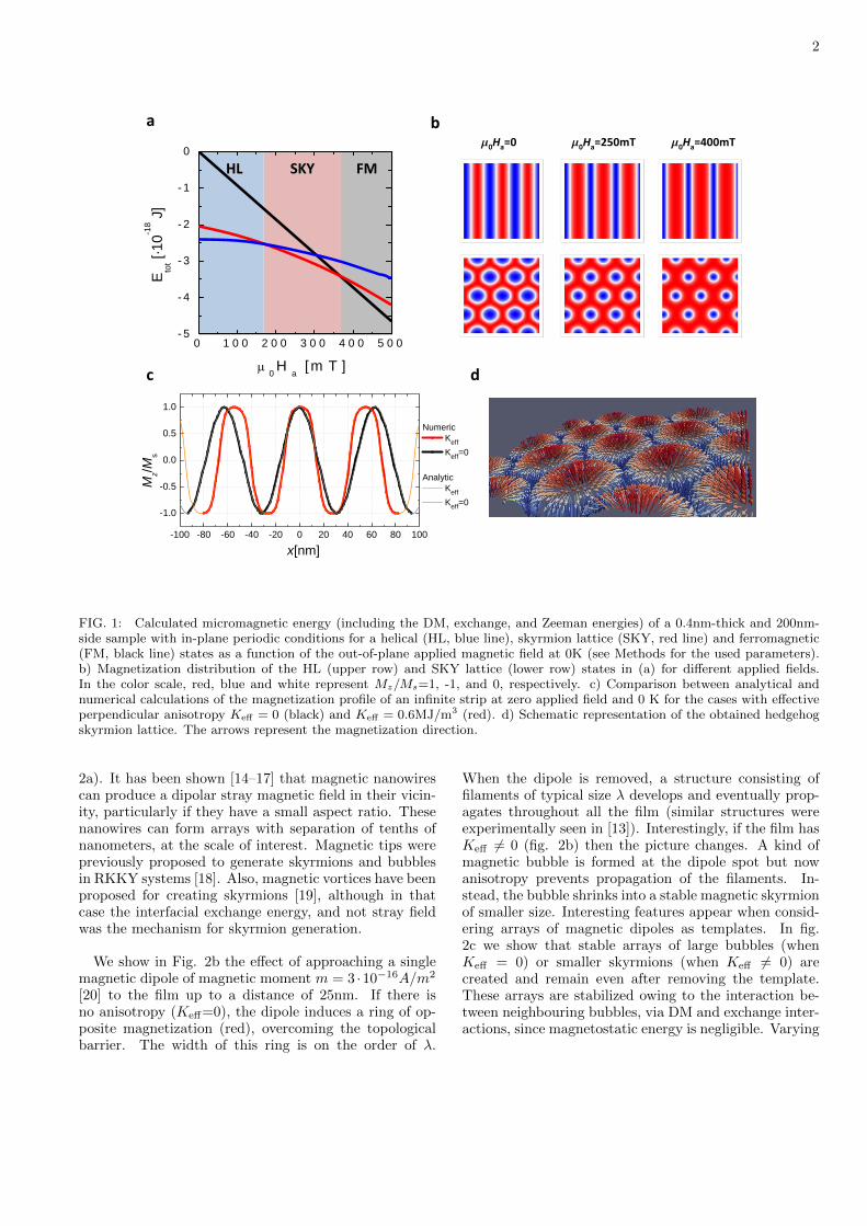
netic configurations as a function of the applied magneticfield Ha. Similar to other studies [3, 4, 9], we find that atzero applied field the minimum energy corresponds to aphase of stripes of undulating out-of-plane component ofthe magnetization, commonly referred to as the helicalphase [9]. We have analytically derived that the mini-mum of energy for an infinitely long (in the y direction)film with no applied field follows a harmonic magneti-zation profile with period 4πA/D, around 63nm in ourstudied case (see Supplementary Material Section II, alsofor the case of a non-zero anisotropy constant Keff or agiven Ha). These solutions are compared in fig. 1c withour numerical simulations for a longitudinal section ofour 2D film in the helical phase. Numerical and ana-lytical results perfectly match, confirming our numericaltechniques.
An hexagonal lattice of skyrmions appear as ametastable solution at low applied fields Ha; this phasebecomes the ground state at Ha ∼ 170mT. The obtainedskyrmions are hedgehog type (fig. 1d) and their size de-creases with increasing Ha, as in [6]. When Ha increasesto about ∼ 370mT, the ferromagnetic state becomes thelowest energy state.
Our calculations show that it is not easy to generateskyrmions starting from configurations such a ferromag-netic state (as previously seen [9, 13]), even at the con-ditions such that a skyrmion lattice has the minimumenergy (e. g. applied field of few hundred mT in ourcase). The reason for that is that generating skyrmionsrequires overcoming a topological barrier [9]. It there-fore becomes essential to design a procedure to generateskyrmions in these magnetic films under general condi-tions, even at zero applied field. We propose here a robustmethod for imprinting skyrmions by bringing a magnetictemplate -with a field profile that can locally induce therequired topological change- close to the film. The ini-tial purely ferromagnetic state will be converted into askyrmion phase by using magnetic templates with theadequate protocol and conditions.
We have seen above that the combination of DMand exchange energies results in a relevant length scaleλ = 4πA/D at which non-trivial structures would tend tobe formed, so we would like our magnetic template fieldsto vary at this scale. We start with dipolar sources (fig.
arX
iv:1
407.
0928
v1 [
cond
-mat
.mtr
l-sc
i] 3
Jul
201
4
2
HLHL SKYSKY FMFM
am0Ha=250mT m0Ha=400mT
b
0 1 0 0 2 0 0 3 0 0 4 0 0 5 0 0- 5
- 4
- 3
- 2
- 1
0
μ 0 H a [m T ]
E tot [·
10-1
8 J]
m0Ha=0
c
-100 -80 -60 -40 -20 0 20 40 60 80 100
-1.0
-0.5
0.0
0.5
1.0
Numeric Keff Keff=0
Analytic Keff Keff=0
x[nm]
Mz/M
s
d
FIG. 1: Calculated micromagnetic energy (including the DM, exchange, and Zeeman energies) of a 0.4nm-thick and 200nm-side sample with in-plane periodic conditions for a helical (HL, blue line), skyrmion lattice (SKY, red line) and ferromagnetic(FM, black line) states as a function of the out-of-plane applied magnetic field at 0K (see Methods for the used parameters).b) Magnetization distribution of the HL (upper row) and SKY lattice (lower row) states in (a) for different applied fields.In the color scale, red, blue and white represent Mz/Ms=1, -1, and 0, respectively. c) Comparison between analytical andnumerical calculations of the magnetization profile of an infinite strip at zero applied field and 0 K for the cases with effectiveperpendicular anisotropy Keff = 0 (black) and Keff = 0.6MJ/m3 (red). d) Schematic representation of the obtained hedgehogskyrmion lattice. The arrows represent the magnetization direction.
2a). It has been shown [14–17] that magnetic nanowirescan produce a dipolar stray magnetic field in their vicin-ity, particularly if they have a small aspect ratio. Thesenanowires can form arrays with separation of tenths ofnanometers, at the scale of interest. Magnetic tips werepreviously proposed to generate skyrmions and bubblesin RKKY systems [18]. Also, magnetic vortices have beenproposed for creating skyrmions [19], although in thatcase the interfacial exchange energy, and not stray fieldwas the mechanism for skyrmion generation.
We show in Fig. 2b the effect of approaching a singlemagnetic dipole of magnetic moment m = 3 ·10−16A/m2
[20] to the film up to a distance of 25nm. If there isno anisotropy (Keff=0), the dipole induces a ring of op-posite magnetization (red), overcoming the topologicalbarrier. The width of this ring is on the order of λ.
When the dipole is removed, a structure consisting offilaments of typical size λ develops and eventually prop-agates throughout all the film (similar structures wereexperimentally seen in [13]). Interestingly, if the film hasKeff 6= 0 (fig. 2b) then the picture changes. A kind ofmagnetic bubble is formed at the dipole spot but nowanisotropy prevents propagation of the filaments. In-stead, the bubble shrinks into a stable magnetic skyrmionof smaller size. Interesting features appear when consid-ering arrays of magnetic dipoles as templates. In fig.2c we show that stable arrays of large bubbles (whenKeff = 0) or smaller skyrmions (when Keff 6= 0) arecreated and remain even after removing the template.These arrays are stabilized owing to the interaction be-tween neighbouring bubbles, via DM and exchange inter-actions, since magnetostatic energy is negligible. Varying

3
Dipole
a
(2) (3)(1) Δt=2nsc
Keff=0
Keff ≠0
300nm
300nm
d
0.0 0.5 1.0 1.5 2.00
50
100
150
200
250
t [ns]z
[nm
]
(1)(2)
(3)
(iv)
(iii)
(ii)
(i)
b
Keff=0
Keff ≠0
900nm
900nm
(ii) (iii)(i) (iv)
FIG. 2: a) Sketch of the magnetization distribution when a magnetic dipole is approaching the thin film in the FM state. b)Magnetization distribution of a 0.4nm-thick and 900nm-side sample with in-plane periodic conditions and with Keff = 0 (upperrow) and Keff = 0.6MJ/m3 (lower row) when a magnetic dipole of magnetic moment md = 3 · 10−16A/m2 is approaching thesample from a distance of 250nm (dipole magnetic field negligible) to 25nm and then is moved away at 250nm. This process iscarried out in 2ns. c) Magnetization distribution of a 0.4nm-thick and 300nm-side sample with in-plane periodic conditions andwith Keff = 0 (upper row) and Keff 6= 0 (lower row) when an array of magnetic dipoles of magnetic moment md = 3 ·10−16A/m2
is approaching the sample following the same process as in (b). The right column corresponds to the magnetization distribution2ns after that the array is removed. The distance between the dipoles of the array is 75nm in both x and y directions. In thecolor scale of (a), (b) and (c), red, blue and white represent Mz/Ms=1, -1, and 0, respectively. Crosses in (b) and (c) indicatethe position of the magnetic dipoles. d) Evolution of the vertical distance between the sample and the single dipole or thedipole array. The points (I), (II), (III) (green triangles) correspond to the plots of (b) and (1), (2), (3) (red dots) correspondto the ones of (c).
the lattice constant of the dipole arrays results in a richbehavior (Supplementary Material section III). An im-portant consequence of these simulations is that stableskyrmions appear in ultrathin magnetic films with mag-netic anisotropy without the need of applying an externaloverall magnetic field. This happens, both in the the caseof a single skyrmion induced by a single magnetic dipole(fog. 2b) and a disordered array of them induced afterapproaching an ordered array of magnetic dipoles (fig.2c).
Another interesting possibility to explore is usingmonopolar field sources (fig. 3a). These can be createdeither by using arrays of long nanowires [14–17] or, alter-
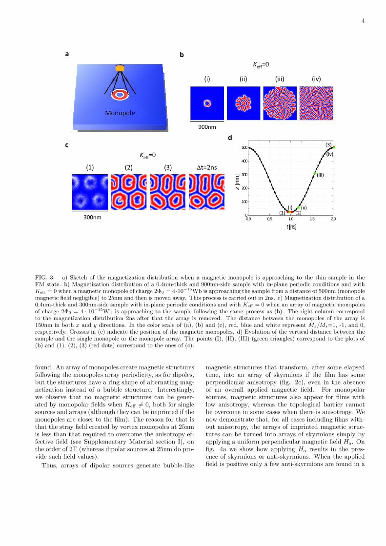
natively, by arrays of superconducting vortices in films[21, 22]. The latter can be tailored with separations offew tenths of nanometers by having an array of antidotsin superconducting films ([23] and references therein).At distance of the order of the Pearl penetration depth(typically, tenths on nanometers [22, 24]), the vortices inthin superconductors create to a good approximation amonopolar field with magnetic charge Q0 = 2Φ0 [21, 22],where Φ0 is the flux quantum. We show in fig. 3b themagnetization distribution of a film with in-plane peri-odic boundary conditions when a monopolar field is ap-proached to a distance of 25nm and then is moved away.Similar structures as those for single dipoles (fig. 2b) are
4
c
(2) (3)(1) Δt=2ns
Keff=0
300nm
aKeff=0
b
900nm
(ii) (iii)(i) (iv)
0.0 0.5 1.0 1.5 2.00
100
200
300
400
500
t [ns]z
[nm
]
d
(1) (2)
(3)
(ii)(i)
(iii)
(iv)
FIG. 3: a) Sketch of the magnetization distribution when a magnetic monopole is approaching to the thin sample in theFM state. b) Magnetization distribution of a 0.4nm-thick and 900nm-side sample with in-plane periodic conditions and withKeff = 0 when a magnetic monopole of charge 2Φ0 = 4·10−15Wb is approaching the sample from a distance of 500nm (monopolemagnetic field negligible) to 25nm and then is moved away. This process is carried out in 2ns. c) Magnetization distribution of a0.4nm-thick and 300nm-side sample with in-plane periodic conditions and with Keff = 0 when an array of magnetic monopolesof charge 2Φ0 = 4 · 10−15Wb is approaching to the sample following the same process as (b). The right column correspondto the magnetization distribution 2ns after that the array is removed. The distance between the monopoles of the array is150nm in both x and y directions. In the color scale of (a), (b) and (c), red, blue and white represent Mz/Ms=1, -1, and 0,respectively. Crosses in (c) indicate the position of the magnetic monopoles. d) Evolution of the vertical distance between thesample and the single monopole or the monopole array. The points (I), (II), (III) (green triangles) correspond to the plots of(b) and (1), (2), (3) (red dots) correspond to the ones of (c).
found. An array of monopoles create magnetic structuresfollowing the monopoles array periodicity, as for dipoles,but the structures have a ring shape of alternating mag-netization instead of a bubble structure. Interestingly,we observe that no magnetic structures can be gener-ated by monopolar fields when Keff 6= 0, both for singlesources and arrays (although they can be imprinted if themonopoles are closer to the film). The reason for that isthat the stray field created by vortex monopoles at 25nmis less than that required to overcome the anisotropy ef-fective field (see Supplementary Material section I), onthe order of 2T (whereas dipolar sources at 25nm do pro-vide such field values).
Thus, arrays of dipolar sources generate bubble-like
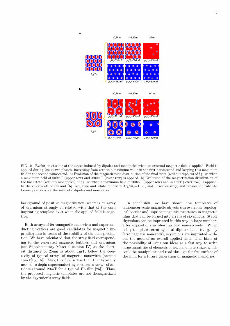
magnetic structures that transform, after some elapsedtime, into an array of skyrmions if the film has someperpendicular anisotropy (fig. 2c), even in the absenceof an overall applied magnetic field. For monopolarsources, magnetic structures also appear for films withlow anisotropy, whereas the topological barrier cannotbe overcome in some cases when there is anisotropy. Wenow demonstrate that, for all cases including films with-out anisotropy, the arrays of imprinted magnetic struc-tures can be turned into arrays of skyrmions simply byapplying a uniform perpendicular magnetic field Ha. Onfig. 4a we show how applying Ha results in the pres-ence of skyrmions or anti-skyrmions. When the appliedfield is positive only a few anti-skyrmions are found in a
5
a
Keff=0
m0Ha=600mTm0Ha=600mTm0Ha=531mT
m0Ha=‐600mTm0Ha=‐600mTm0Ha=‐531mT
t=2nst=1,17nst=0,78ns
b
Keff=0
m0Ha=600mTm0Ha=600mTm0Ha=531mT
m0Ha=‐400mTm0Ha=‐400mTm0Ha=‐354mT
t=2nst=1,17nst=0,78ns
FIG. 4: Evolution of some of the states induced by dipoles and monopoles when an external magnetic field is applied. Field isapplied during 2ns in two phases: increasing from zero to a maximum value in the first nanosecond and keeping this maximumfield in the second nanosecond. a) Evolution of the magnetization distribution of the final state (without dipoles) of fig. 2c whena maximum field of 600mT (upper row) and -600mT (lower row) is applied. b) Evolution of the magnetization distribution ofthe final state (without monopoles) of fig. 3c when a maximum field of 600mT (upper row) and -400mT (lower row) is applied.In the color scale of (a) and (b), red, blue and white represent Mz/Ms=1, -1, and 0, respectively, and crosses indicate theformer positions for the magnetic dipoles and monopoles.
background of positive magnetization, whereas an arrayof skyrmions strongly correlated with that of the usedimprinting template exist when the applied field is nega-tive.
Both arrays of ferromagnetic nanowires and supercon-ducting vortices are good candidates for magnetic im-printing also in terms of the stability of their magnetiza-tion. We have calculated that the stray field correspond-ing to the generated magnetic bubbles and skyrmions(see Supplementary Material section IV) at the short-est distance of 25nm is about 1mT, below the coer-civity of typical arrays of magnetic nanowires (around15mT[15, 16]). Also, this field is less than that typicallyneeded to depin superconducting vortices in arrays of an-tidots (around 20mT for a typical Pb film [25]). Thus,the proposed magnetic templates are not demagnetizedby the skyrmion’s stray fields.
In conclusion, we have shown how templates ofnanometer-scale magnetic objects can overcome topolog-ical barrier and imprint magnetic structures in magneticfilms that can be turned into arrays of skyrmions. Stableskyrmions can be imprinted in this way in large numbersafter expositions as short as few nanoseconds. Whenusing templates creating local dipolar fields (e. g. byferromagnetic nanorods), skyrmions are imprinted with-out the need of an overall applied field. This hints atthe possibility of using our ideas as a fast way to writelarge quantities of elements of few nanometers size, whichcould be manipulate and read through the free surface ofthe film, for a future generation of magnetic memories.

6
Acknowledgements
We thank Spanish projects NANOSELECT(CSD2007-00041) and MAT2012- 35370 for finan-cial support. AS acknowledges financial support fromICREA Academia (Generalitat de Catalunya) .
Corresponding author
Alvaro Sanchez ([email protected])
[1] Ferriani, P. et al. Phys. Rev. Lett. 101, 027271 (2008).[2] Heide, M., Bihlmayer, G. & Blugel, S. Phys. Rev. B 78,
140403 (2008).[3] Muhlbauer, S. et al. Science 323, 915-919 (2009).[4] Yu, X. Z. et al. Real-space observation of a two-
dimensional skyrmion crystal. Nature 465, 901-904(2009).
[5] Chappert, C. et al. Science 280, 19191922 (1998).[6] Sampaio, J. et al. Nature Nanotech. 8, 839-844 (2013).[7] Fert, A., Cros, V. and Sampaio, J. Nature Nanotech. 8,
152156 (2013).[8] Felser, C. Angew. Chem. Int. Ed. 52, 16311634 (2013).[9] Nagaosa, N. and Tokura, Y. Nature Nanotech. 8, 899-911
(2013).[10] Agramunt-Puig, S. et al. Appl. Phys. Lett. 104, 012407
(2014).[11] Rohart, S. & Thiaville, A. Phys. Rev. B. 88, 184422
(2013).[12] Ohe, J.-i. & Shimada, Y. Appl. Phys. Lett. 103, 242403
(2013).[13] Milde, P. et al. Science 340, 10761080 (2013).[14] Ross, C. A. and Hwang, M. and Shima, M. and Cheng, J.
Y. and Farhoud, M. and Savas, T. A. and Smith, Henry I.and Schwarzacher, W. and Ross, F. M. and Redjdal, M.and Humphrey, F. B. Phys. Rev. B 65, 144417 (2002).
[15] Fernandez-Pacheco, A.; Serrano-Ramon, L.; Michalik, J.;Ibarra, M. R.; De Teresa, J. M.; OBrien, L.; Petit, D.;Lee, J.; Cowburn, R. P. Sci. Rep. 3, 1492 (2013).
[16] Nikulina, E., Idigoras, O., Vavassori, P., Chuvilin, A. andBerger, A. Appl. Phys. Lett. 100, 142401 (2012).
[17] De Teresa, J. M., and Rosa Crdoba, R. ACS Nano 8,3788-3795 (2014).
[18] Kirakosyana, A. S. and Pokrovskyc, V. L. Journal ofMagnetism and Magnetic Materials 305 413422 (2006).
[19] Sun, L., Cao, R. X., Miao, B. F., Feng, Z., You, B., Wu,D., Zhang, W., Hu, A., and Ding, H. F. Phys. Rev. Lett.110, 167201 (2013).
[20] Li, H. et al. IEEE. Trans. Magn. 7, 2570-2578 (2010).[21] Carneiro, G. and Brandt, E. H., Phys. Rev. B 61, 6370–
6376 (2000).[22] Romero-Isart, O., Navau, C., Sanchez, A., Zoller, P. and
Cirac, J. I. Phys. Rev. Lett. 111, 145304 (2013).[23] Moshchalkov, V. V., Woerdenweber, R. and Lang, W.
Nanoscience and Engineering in Superconductivity. Ch.2 (Springer-Verlag, Berlin Heidelberg, 2010).
[24] Pearl, J. Appl. Phys. Lett. 5, 65 (1964).[25] Silhanek, A. V. , Raedts, S., Lange, M., and
Moshchalkov, V. V. Phys. Rev. B 67, 064502 (2003).
Copyright © 2022 FDOKUMEN