Implementation of Industrial Waste Water Purification & Bottle ...
7
ISSN (Print) : 2320 – 3765 ISSN (Online): 2278 – 8875 International Journal of Advanced Research in Electrical, Electronics and Instrumentation Engineering (A High Impact Factor, Monthly, Peer Reviewed Journal) Website: www.ijareeie.com Vol. 8, Issue 1, January 2019 Copyright to IJAREEIE DOI:10.15662/IJAREEIE.2019.0801008 35 Implementation of Industrial Waste Water Purification & Bottle Filling System Using PLC Vikas Karade 1 , Ambadas Shinde 2 , Sagar Sutar 3 , Assistant Professor, Dept. of Instrumentation Engineering, PVPIT Budhgaon, Sangli, Maharashtra, India 1 Assistant Professor, Dept. of Electronics Engineering, PVPIT Budhgaon, Sangli, Maharashtra, India 2 Assistant Professor, Dept. of Instrumentation Engineering, PVPIT Budhgaon, Sangli, Maharashtra, India 3 ABSTRACT: The provision of clean water is a major issue. There are multiple solutions available for water purification and supply. Different systems of water purification have different solutions. Various stages in filtrations are used in this process. TDS (Total Dissolved Salts) & pH control in impure water with the help of reverse osmosis technology and dosing of chlorine and sodium bicarbonate solutions in proper amount, method is presented in this paper. The automated process of bottle filling station using IR sensor is also mentioned in detail. The results gained in water purification are very good and purified water is potable and free from harmful chemicals and salts. KEYWORDS: Waste water treatment, Water purification, bottle filling, PLC. I. INTRODUCTION The water is used for a variety of purposes like drinking, washing, recreation as well as for various industrial applications [1]. Water is the most fundamental factor needed for all organisms on this earth. The percentage of naturally available drinking water is less than 1% of the total available water on the earth [2]. Due to the ever- increasing population of world, the demand as well as consumption of water is also escalating. The water available in natural reservoirs is getting polluted because of mixing of unwanted industrial waste water without any proper treatment. As a result of this pollution, the water in these reservoirs contains various chemicals, salts and other impurities that make it unfit for drinking purpose. Therefore there is need to purify the water. Reverse Osmosis (RO), is a very popular and effective technique is used to purify water. It removes impure particles, salts and other chemicals from the water and gives only pure water. The rejected water is separated from the pure water which is indeed potable. Here, along with Reverse Osmosis we are introducing chemical dosing of chlorine and sodium bicarbonate, to remove all the bacteria’s from the water as well as to add good taste to it. Also due to the dosing of chemicals the pH and TDS of the pure water is maintained as per the required standards for potable water. II. AUTOMATION IN WATER PURIFICATION PLC (Programmable Logic Control) is used for the water purification to make the process automatic. It is been used for the efficient working of the system, to reduce the manual work and to maintain accuracy of the TDS. The automating filling line helps in packaging of the pure water in bottles or jars which gives total industrial solution for water purification. Process loop diagram is as shown in figure 1. There are two modes over which the water purification line can run i.e. auto mode and manual mode [6].
-
Upload
khangminh22 -
Category
Documents
-
view
3 -
download
0
Transcript of Implementation of Industrial Waste Water Purification & Bottle ...
ISSN (Print) : 2320 – 3765 ISSN (Online): 2278 – 8875
International Journal of Advanced Research in Electrical,
Electronics and Instrumentation Engineering (A High Impact Factor, Monthly, Peer Reviewed Journal)
Website: www.ijareeie.com
Vol. 8, Issue 1, January 2019
Copyright to IJAREEIE DOI:10.15662/IJAREEIE.2019.0801008 35
Implementation of Industrial Waste Water Purification & Bottle Filling System Using
PLC Vikas Karade1, Ambadas Shinde2, Sagar Sutar3,
Assistant Professor, Dept. of Instrumentation Engineering, PVPIT Budhgaon, Sangli, Maharashtra, India1
Assistant Professor, Dept. of Electronics Engineering, PVPIT Budhgaon, Sangli, Maharashtra, India2
Assistant Professor, Dept. of Instrumentation Engineering, PVPIT Budhgaon, Sangli, Maharashtra, India3
ABSTRACT: The provision of clean water is a major issue. There are multiple solutions available for water purification and supply. Different systems of water purification have different solutions. Various stages in filtrations are used in this process. TDS (Total Dissolved Salts) & pH control in impure water with the help of reverse osmosis technology and dosing of chlorine and sodium bicarbonate solutions in proper amount, method is presented in this paper. The automated process of bottle filling station using IR sensor is also mentioned in detail. The results gained in water purification are very good and purified water is potable and free from harmful chemicals and salts.
KEYWORDS: Waste water treatment, Water purification, bottle filling, PLC.
I. INTRODUCTION
The water is used for a variety of purposes like drinking, washing, recreation as well as for various industrial applications [1]. Water is the most fundamental factor needed for all organisms on this earth. The percentage of naturally available drinking water is less than 1% of the total available water on the earth [2]. Due to the ever-increasing population of world, the demand as well as consumption of water is also escalating. The water available in natural reservoirs is getting polluted because of mixing of unwanted industrial waste water without any proper treatment. As a result of this pollution, the water in these reservoirs contains various chemicals, salts and other impurities that make it unfit for drinking purpose. Therefore there is need to purify the water. Reverse Osmosis (RO), is a very popular and effective technique is used to purify water. It removes impure particles, salts and other chemicals from the water and gives only pure water. The rejected water is separated from the pure water which is indeed potable. Here, along with Reverse Osmosis we are introducing chemical dosing of chlorine and sodium bicarbonate, to remove all the bacteria’s from the water as well as to add good taste to it. Also due to the dosing of chemicals the pH and TDS of the pure water is maintained as per the required standards for potable water.
II. AUTOMATION IN WATER PURIFICATION
PLC (Programmable Logic Control) is used for the water purification to make the process automatic. It is been used for the efficient working of the system, to reduce the manual work and to maintain accuracy of the TDS. The automating filling line helps in packaging of the pure water in bottles or jars which gives total industrial solution for water purification. Process loop diagram is as shown in figure 1. There are two modes over which the water purification line can run i.e. auto mode and manual mode [6].

ISSN (Print) : 2320 – 3765 ISSN (Online): 2278 – 8875
International Journal of Advanced Research in Electrical,
Electronics and Instrumentation Engineering (A High Impact Factor, Monthly, Peer Reviewed Journal)
Website: www.ijareeie.com
Vol. 8, Issue 1, January 2019
Copyright to IJAREEIE DOI:10.15662/IJAREEIE.2019.0801008 36
Fig. 1 Process Diagram
When process starts, the limit switches act as level indicator, which continuously gives signal to the PLC. The High Level Switches act as interlock to stop the earlier phase and further to proceed with the next phase. Thus the level transducers help to ON/OFF the respective output pumps of the particular phase. In phase II, the purification of the raw water is done with the help of pumps, filters and R.O. membrane. The chemical dosing of NaHCO3 and chlorine is in line with the process. The solenoid valve OPENS or CLOSES according to the dosing required. As soon as the level of water in the product water tank reaches high level the bottle filling, phase III starts. In order to control the motion of the motor, I.R. sensor is used which acts as an interlock. As soon as there is obstruction in between the I.R. receiver and transmitter, it stops the motor. The bottle filling is done with the help of a timer. When the timer reaches the required time for bottle filling, the respective pump and solenoid valve gets OFF automatically. As it is a batch process, the annunciator acts as an alarm for the operator to know that the process is complete. The whole process can be stopped at any given time with the help of the STOP button. Purification Process Water purification include following steps as shown in figure 2: 1. Raw water: TDS range is from 150-900 depending upon the water source. It contains high amount of dissolved impurities along with salts, bacteria and Virus. Sediment Filter: Physical impurities such as suspended solids, sand, silt, dust and rust are removed by 5 micron PP Filter. 2. Carbon Filter: Colour, odour, chlorine and organic impurities are removed by adsorption on highly activated granular carbon. Stops left-out chlorine and particles less than 5 micron. This increases life of the highly sensitive RO membrane.
ISSN (Print) : 2320 – 3765 ISSN (Online): 2278 – 8875
International Journal of Advanced Research in Electrical,
Electronics and Instrumentation Engineering (A High Impact Factor, Monthly, Peer Reviewed Journal)
Website: www.ijareeie.com
Vol. 8, Issue 1, January 2019
Copyright to IJAREEIE DOI:10.15662/IJAREEIE.2019.0801008 37
Raw Water
Sediment
filter
Carbon filter
Booster
pump
RO Membrane
Post carbon filter
Pure water
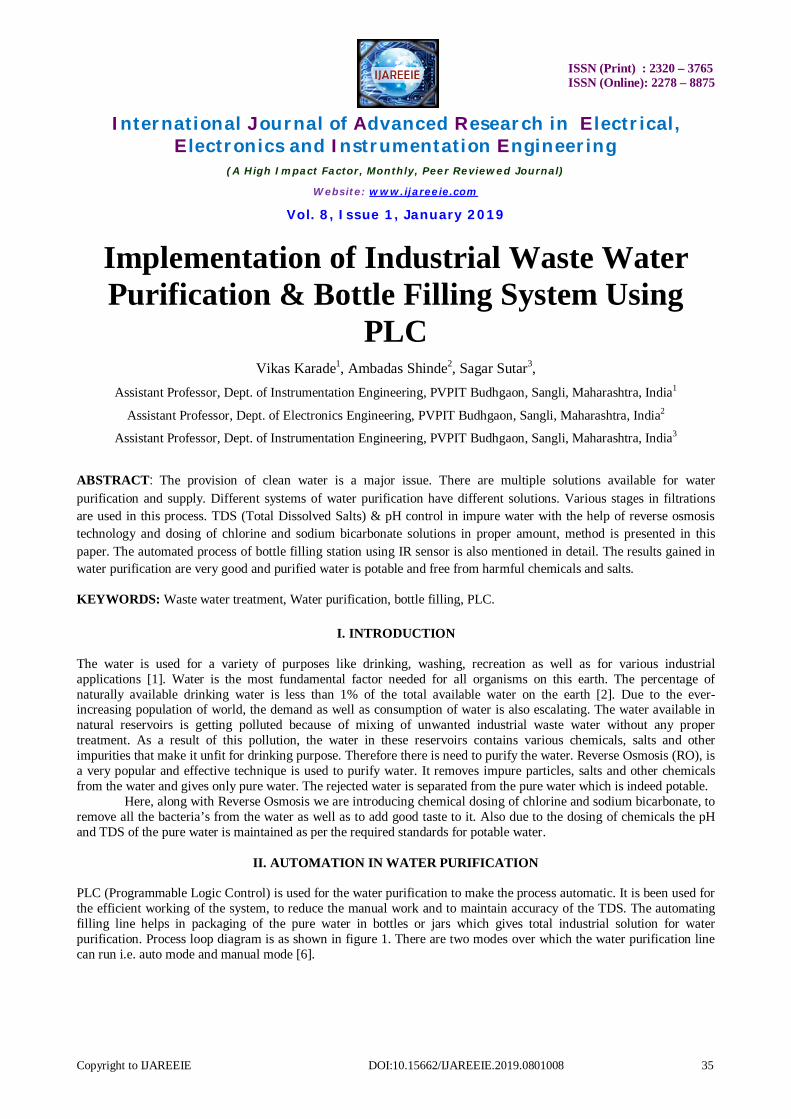
Fig. 2 Purification Process
3. Booster Pump: It creates heavy pressure in water and pushes it into the RO Membrane. 4. RO Membrane: It is specially designed to remove dissolved chemical impurities. This semi-permeable membrane has 0.0001 micron pore diameter. These pores being much smaller than both Virus and Bacteria don’t allow them to pass through, apart from all other impurities. 5. Post Carbon Filter: It has been designed to prevent any possible growth of bacteria at the point of use. Also restores natural taste of water. 6. Pure Water: The water obtained at the final stage after post filter is pure having TDS in the range of 25-35 and pH of around 6.8-7.2
III. WATER PURIFICATION HARDWARE COMPONENTS
Programmable Logic Controller: PLC is a digital electronic device, which uses a programmable memory that coordinates input and output modules to control processes. A PLC has following hardware components: Input / Output modules Processor Power supply Programming devices
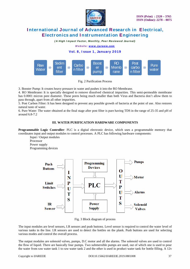
Fig. 3 Block diagram of process
The input modules are level sensors, I.R sensors and push buttons. Level sensor is required to control the water level of various tanks in the line. I.R sensors are used to detect the bottles on the plank. Push buttons are used for selecting various modes and control the overall process. The output modules are solenoid valves, pumps, D.C motor and all the alarms. The solenoid valves are used to control the flow of liquid. There are basically four pumps. Two submersible pumps are used, out of which one is used to pour the water from raw water tank 1 to raw water tank 2 and the other is used in product water tank for bottle filling. A 12v
ISSN (Print) : 2320 – 3765 ISSN (Online): 2278 – 8875
International Journal of Advanced Research in Electrical,
Electronics and Instrumentation Engineering (A High Impact Factor, Monthly, Peer Reviewed Journal)
Website: www.ijareeie.com
Vol. 8, Issue 1, January 2019
Copyright to IJAREEIE DOI:10.15662/IJAREEIE.2019.0801008 38
D.C pump is used to force the water from raw water tank 2 to sediment filter. A R.O Booster pump is used to suck the water from the carbon filter and force it on to the R.O Membrane. A 12v D.C Motor is used to rotate the wooden plank in the bottle filling station on which the bottles are kept. As we know that one programming device, such as a personal computer or a laptop is necessary to interface with the PLC. We need a programming device connected to the PLC. Programming devices helps us to enter the required program/commands into the PLC memory and troubleshoot the PLC ladder logic program. The program is entered in the form of relay ladder logic and is responsible to check the operation sequence. Three types of programming devices used are: 1. Hand held terminals 2. Dedicated terminals 3. Personal computers The PLC, which we have used, works on the supply voltage of 85V to 264V AC and supply frequency up to 63 Hz. PLC’s have two types of power supplies: 1. Internal power supply: This powers the processor module (CPU) 2. External power supply: This gives AC or DC power supply to I/O modules. The power supply provides DC power to the other I/O modules, which are inserted in the rack. The processor requires low DC power. The AC power supply of 120 or 240 volts needs to be converted into low DC power for the internal power requirements of I/O modules.[10] Wecon HMI: Generally, the goal of human-machine interaction engineering is to produce a user interface which makes it easy, efficient and enjoyable to operate a machine in the way which produces the desired result. This generally means that the operator needs to provide minimal input to achieve the desired output, and also that the machine minimizes undesired outputs to the human. Applied input allows the users to manipulate a system output, allowing the system to indicate the effects of the users' manipulation.[11] Touch screens displays accepts input by touch of fingers or a stylus. Used in a growing amount of mobile devices and many types of point of sale, industrial processes and machines, self-service machines etc. The material used for the frame is 25x3 Ms (mild steel). The dimensions of the frame are 6 feet x 5 feet x 1.5 feet (h x l x w). We have divided the frame into 3 parts in which 1st part consists of raw water tank section in which two raw water tanks are situated one above the other separated by angles. The 2nd section consists of main water purification line consisting of various filters and pumps. The 3rd section is the bottle filling station where 4 bottles are placed on a circular conveyer operated by motor. 1. Sediment Filter: To sediment the solid suspended particles. 2. Carbon Activated Filter: To trap solid particles suspended in water. 3. RO Membrane: It is reverse osmosis element and used to reject the total dissolved salts present in water in the form of rejected water and purify the water completely 4. Carbon Post Filter: To add taste to the water 5. TDS Meter: To detect and indicate the total dissolved salts (TDS) concentration in water 6. DB9: Serial communication component 7. Relays: 24 V DC, 230V AC
ISSN (Print) : 2320 – 3765 ISSN (Online): 2278 – 8875
International Journal of Advanced Research in Electrical,
Electronics and Instrumentation Engineering (A High Impact Factor, Monthly, Peer Reviewed Journal)
Website: www.ijareeie.com
Vol. 8, Issue 1, January 2019
Copyright to IJAREEIE DOI:10.15662/IJAREEIE.2019.0801008 39
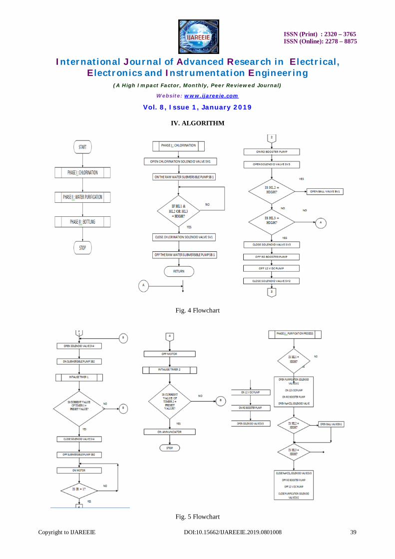
IV. ALGORITHM
Fig. 4 Flowchart
Fig. 5 Flowchart

ISSN (Print) : 2320 – 3765 ISSN (Online): 2278 – 8875
International Journal of Advanced Research in Electrical,
Electronics and Instrumentation Engineering (A High Impact Factor, Monthly, Peer Reviewed Journal)
Website: www.ijareeie.com
Vol. 8, Issue 1, January 2019
Copyright to IJAREEIE DOI:10.15662/IJAREEIE.2019.0801008 40
V. RESULT AND DISCUSSION
Fig. 6 Automation in Water Purification & Bottle Filling Process
Figure 6 shows the implemented system of water purification and bottle filling using PLC 1. When START button is pressed, the PHASE I i.e. Raw Water Tanks start getting filled. 2. After the PHASE I get complete PHASE II, purification of the Water from Raw Water Tank. 3. PHASE III of bottle filling is also achieved. 4. The limit switches continuously measure the level of the water in the respective tanks and sends the signal to PLC. 5. 5. The PLC controls the output side accordingly. 6. The I.R. sensor stops the motion of the motor during PHASE III. 7. After the whole batch process is completed hotter sounds. 8. When STOP button is pressed the whole process stops at any point.
VI. CONCLUSION
Reverse osmosis is one of the best solutions to purify industrial waste water. Using this technique water impurities which are in chemical form and bacteria’s from the water are removed and good test is added to water. Due dosing of chemicals water TDS & pH is maintained according to standards. This results in separation of portable form of pure water from industrial waste.
REFERENCES
[1] Shweta Chauhan, K. C. Gupta, Jyoti Singh, “Selection of drinking water with the application of neutral extracts, Global Biosciences Journal, Vol. 4, Issue 1, 2015, p.p. 1861-1866.
[2] Carl Lilja, “Sustainable water purification technology in Zambia”, Kungsholmens Gymnasium, Beatrice Hallmark EN3A. [3] S. S. Turkar, D. B. Bharti and G. S. Gaikwad, “Various methods involved in water treatment to control water pollution”, J. Chem. & Pharma.
Research, 2011, 3(2): 58-65. [4] Bruce I. Dvorak, Extension Environmental engineering specialist; Sharon O, Skipton, Neb Guide, “Drinking water treatment: Reverse
osmosis”. [5] Bruce I. Dvorak, “Drinking water treatment reverse osmosis”. [6] Arthur Fisher, Jennifer Reisig, “Reverse osmosis”.

ISSN (Print) : 2320 – 3765 ISSN (Online): 2278 – 8875
International Journal of Advanced Research in Electrical,
Electronics and Instrumentation Engineering (A High Impact Factor, Monthly, Peer Reviewed Journal)
Website: www.ijareeie.com
Vol. 8, Issue 1, January 2019
Copyright to IJAREEIE DOI:10.15662/IJAREEIE.2019.0801008 41
[7] W.G. Andrew, H.B. Williams, “Applied Instrumentation In The Process Industry”, Volume II / Second Edition, Gulf Publishing Company, Houston Texas, 1980.
[8] S. K. Singh, “Industrial instrumentation and control”, second edition. [9] B. G. Liptak, “Instrument Engineers Handbook, Process Control”, Butterworth Heinemann UK and Europe 1995. [10] Shenzhen Co-Trust 224+ PLC Manual [11] Wecon HMI User Manual [12] Dobrivoje Popovic, Vijay P. Bhatkar, “Distributed Computer Control for Industrial Automation”, Marcel Dekker Inc, New York 10016