Near-Eye Display and Tracking Technologies for Virtual and ...
image based eye gaze tracking and its applications - arXiv
177
IMAGE BASED EYE GAZE TRACKING AND ITS APPLICATIONS Anjith George arXiv:1907.04325v1 [cs.CV] 9 Jul 2019
-
Upload
khangminh22 -
Category
Documents
-
view
0 -
download
0
Transcript of image based eye gaze tracking and its applications - arXiv

IMAGE BASED EYE GAZE
TRACKING AND ITS
APPLICATIONS
Anjith George
arX
iv:1
907.
0432
5v1
[cs
.CV
] 9
Jul
201
9

IMAGE BASED EYE GAZE TRACKING AND
ITS APPLICATIONS
Thesis submitted toIndian Institute of Technology, Kharagpur
for the award of the degree
of
Doctor of Philosophy
by
Anjith George
under the guidance of
Prof. Aurobinda Routray(Electrical Engineering Department)
ELECTRICAL ENGINEERING DEPARTMENTINDIAN INSTITUTE OF TECHNOLOGY KHARAGPUR
AUGUST 2017
c©2017, Anjith George. All rights reserved.


APPROVAL OF THE VIVA-VOCE BOARD
—/—/2017
Certified that the thesis entitled IMAGE BASED EYE GAZE TRACKING AND
ITS APPLICATIONS submitted by ANJITH GEORGE to the Indian Institute
of Technology, Kharagpur, for the award of the degree Doctor of Philosophy has
been accepted by the external examiners and that the student has successfully
defended the thesis in the viva-voce examination held today.
(Member of the DSC) (Member of the DSC) (Member of the DSC)
(Member of the DSC) (Supervisor)
(External Examiner) (Member of the DSC) (Chairman)


Electrical Engineering DepartmentIndian Institute of Technology, KharagpurKharagpur, India-721302
Certificate
This is to certify that this thesis entitled Image based eye gaze tracking
and its applications submitted by Anjith George, to the Indian Institute of
Technology, Kharagpur, is a record of bona fide research work carried out under
my supervision and is worthy of consideration for award of Ph.D of the Institute.
Prof. Aurobinda Routray
Electrical Engineering Department
Indian Institute of Technology, Kharagpur
India- 721302.
I.I.T. Kharagpur
August, 2017


- To my parents -
- To my loving wife Neethu -


“Research is formalized curiosity. It is poking and prying with apurpose.”
- Zora Neale Hurston


Declaration
I certify that
a. the work contained in the thesis is original and has been done by me under
the guidance of my supervisor;
b. the work has not been submitted to any other institute for any other degree
or diploma;
c. I have followed the guidelines provided by the Institute in preparing the
thesis;
d. I have conformed to ethical norms and guidelines while writing the thesis;
e. whenever I have used materials (data, models, figures and text) from other
sources, I have given due credit to them by citing them in the text of the
thesis, and giving their details in the references, and taken permission from
the copyright owners of the sources, whenever necessary.
Anjith George

Acknowledgment
I am grateful to my supervisor Prof. Aurobinda Routray for his constant support
and encouragement throughout the research work. This thesis would not have
taken its current shape without his constant motivation and support. I am thank-
ful to him for his insightful comments and willingness to help whenever needed.
I would like to thank the members of the Doctoral Scrutiny Committee, Prof.
Pallab Dasgupta, Prof. P. K. Dutta, and Prof. A.K. Deb for their valuable sugges-
tions and interactions throughout the tenure. I am thankful to Head, Department
of Electrical Engineering, IIT Kharagpur, for providing the facilities to carry out
my research work. I am also grateful to all other faculty members of the depart-
ment for the help received during my research work.
I am grateful to Prof. P. Patnaik, Department of Humanities and Social Sci-
ence, IIT Kharagpur for the help with experiment designs and valuable discussions.
I also appreciate the support from Prof. Rajlakshmi Guha for the experiment de-
sign and analysis. I am also grateful to Department of Information Technology,
Govt. of India and Samsung Electronics for funding various phases of the project.
I would like to acknowledge the help and support of all my colleagues and
labmates from NEX and RTES Lab, Department of Electrical Engineering. Spe-
cial thanks to Anand Sahadev, Anirban Dasgupta, SL Happy and Ramnarayan
Mohanty for the support and insightful discussions.
Last but not the least, I would like to thank my parents for their support
throughout these years. I would like to thank my wife Neethu for her wholehearted
support and encouragements through the difficult times. This thesis would not
have been possible without her sacrifice, love and support.
Anjith George
xiii

Abstract
Eye movements play a vital role in perceiving the world. Eye gaze can give a
direct indication of the users point of attention, which can be useful in improving
human-computer interaction. Gaze estimation in a non-intrusive manner can make
human-computer interaction more natural. Eye tracking can be used for several
applications such as fatigue detection, biometric authentication, disease diagnosis,
activity recognition, alertness level estimation, gaze contingent display, human-
computer interaction, etc. Even though eye tracking technology has been around
for many decades, it has not found much use in consumer applications. The
main reasons are the high cost of eye tracking hardware and lack of consumer
level applications. In this work, we attempt to address these two issues. In the
first part of this work, image-based algorithms are developed for gaze tracking
which includes a new two-stage iris center localization algorithm. The iris center
location along with eye corners are used to develop a gaze tracking framework
which can operate even with off the shelf webcams. We have further developed
an algorithm for head-mounted eye trackers. Most of the available algorithms
perform well only in controlled environments. In order to make eye tracking
ubiquitous, they should work in outdoor conditions as well. To this end, we have
developed a new algorithm which works in challenging conditions such as motion
blur, glint and varying illumination levels. A person independent gaze direction
classification framework is also developed which eliminates the requirement of user
specific calibration. A convolutional neural network based classifier is proposed
for real-time gaze direction classification.
In the second part of this work, we have developed two applications which
can benefit from eye tracking data. A new framework for biometric identification
based on eye movement parameters is developed. A score fusion methodology with
a new set of features extracted from fixations and saccades is adopted for biometric
identification. The addition of eye movement features along with the conventional
xv

iris recognition systems can lead to a counterfeit-proof biometric modality with
inbuilt liveliness detection capability. A framework for activity recognition, using
gaze data from a head mounted eye tracker is also developed. The information
from gaze data, ego-motion, and visual features are integrated to classify the
activities. This approach improves the classification accuracy in indoor conditions
where conventional activity detection modalities fail.
Keywords: Eye detection, Eye tracking, Gaze tracking, Eye movement bio-
metrics, Egocentric activity recognition.
xvi

Contents
Title Page i
Approval of the Viva-Voce board iii
Certificate by the Supervisor v
Declaration xi
Acknowledgement xiii
Abstract xv
List of Abbreviations xxiii
1 Introduction 1
1.1 Introduction . . . . . . . . . . . . . . . . . . . . . . . . . . . . . . . 1
1.2 Motivation . . . . . . . . . . . . . . . . . . . . . . . . . . . . . . . 2
1.3 Anatomy of eye . . . . . . . . . . . . . . . . . . . . . . . . . . . . . 3
1.3.1 External anatomy . . . . . . . . . . . . . . . . . . . . . . . . 3
1.3.2 Imaging of eye region . . . . . . . . . . . . . . . . . . . . . . 4
1.4 Methods for measuring eye movements . . . . . . . . . . . . . . . . 4
1.5 Image based eye gaze tracking . . . . . . . . . . . . . . . . . . . . . 5
1.5.1 Remote eye trackers . . . . . . . . . . . . . . . . . . . . . . 7
1.5.2 Head mounted eye trackers . . . . . . . . . . . . . . . . . . . 7
1.6 Taxonomy of eye movements . . . . . . . . . . . . . . . . . . . . . . 8
1.6.1 Fixations . . . . . . . . . . . . . . . . . . . . . . . . . . . . 8
1.6.2 Saccades . . . . . . . . . . . . . . . . . . . . . . . . . . . . . 8
1.6.3 Smooth pursuit . . . . . . . . . . . . . . . . . . . . . . . . . 8
xvii
CONTENTS
1.6.4 Vergence . . . . . . . . . . . . . . . . . . . . . . . . . . . . . 8
1.6.5 Nystagmus . . . . . . . . . . . . . . . . . . . . . . . . . . . . 9
1.7 Applications of eye gaze tracking . . . . . . . . . . . . . . . . . . . 9
1.8 Objectives and scope of the thesis . . . . . . . . . . . . . . . . . . . 10
1.9 Contributions of the thesis . . . . . . . . . . . . . . . . . . . . . . . 11
1.10 Thesis organization . . . . . . . . . . . . . . . . . . . . . . . . . . . 12
2 Eye Localization for Gaze Tracking in Low-Resolution Images 15
2.1 Introduction . . . . . . . . . . . . . . . . . . . . . . . . . . . . . . . 15
2.2 Related works . . . . . . . . . . . . . . . . . . . . . . . . . . . . . . 17
2.3 Proposed algorithm . . . . . . . . . . . . . . . . . . . . . . . . . . . 20
2.3.1 Face detection and eye region localization . . . . . . . . . . 20
2.3.2 Iris center localization . . . . . . . . . . . . . . . . . . . . . 21
2.3.2.1 Coarse iris center detection . . . . . . . . . . . . . 21
2.3.2.2 Sub-pixel edge refining and ellipse fitting . . . . . . 24
2.3.3 Iris tracking . . . . . . . . . . . . . . . . . . . . . . . . . . . 24
2.3.4 Eye closure detection . . . . . . . . . . . . . . . . . . . . . . 26
2.3.5 Eye corner detection and tracking . . . . . . . . . . . . . . . 26
2.3.6 Gaze estimation . . . . . . . . . . . . . . . . . . . . . . . . . 27
2.3.6.1 Calibration . . . . . . . . . . . . . . . . . . . . . . 27
2.3.6.2 Estimation of PoG . . . . . . . . . . . . . . . . . . 28
2.4 Experiments . . . . . . . . . . . . . . . . . . . . . . . . . . . . . . . 29
2.4.1 Experiments on IC localization . . . . . . . . . . . . . . . . 30
2.4.1.1 Evaluation method . . . . . . . . . . . . . . . . . . 30
2.4.1.2 Experiments in BioID and Gi4E Databases . . . . 30
2.4.1.3 Comparison with state of the art methods . . . . . 33
2.4.2 Experiment with our database . . . . . . . . . . . . . . . . . 36
2.4.2.1 Evaluation of gaze estimation accuracy . . . . . . 36
2.4.2.2 Experiment for eye closure detection . . . . . . . . 38
2.4.3 Discussions . . . . . . . . . . . . . . . . . . . . . . . . . . . 39
2.5 Summary . . . . . . . . . . . . . . . . . . . . . . . . . . . . . . . . 41
3 Pupil Center Localization Algorithm for Near Infrared Images 43
3.1 Introduction . . . . . . . . . . . . . . . . . . . . . . . . . . . . . . . 43
3.2 Related works . . . . . . . . . . . . . . . . . . . . . . . . . . . . . . 45
3.3 Proposed method . . . . . . . . . . . . . . . . . . . . . . . . . . . . 48
3.3.1 Preprocessing and edge detection . . . . . . . . . . . . . . . 48
xviii
CONTENTS
3.3.2 Edge selection and candidate filtering . . . . . . . . . . . . . 49
3.3.3 Candidate detection with MSER . . . . . . . . . . . . . . . 50
3.3.4 Tracking framework . . . . . . . . . . . . . . . . . . . . . . . 52
3.3.5 Comparison with state of the art method . . . . . . . . . . . 53
3.4 Experiments . . . . . . . . . . . . . . . . . . . . . . . . . . . . . . . 53
3.4.1 Labeled Pupils in the Wild database . . . . . . . . . . . . . 53
3.4.2 Evaluation of the algorithm . . . . . . . . . . . . . . . . . . 54
3.5 Discussions . . . . . . . . . . . . . . . . . . . . . . . . . . . . . . . 57
3.5.1 Execution time . . . . . . . . . . . . . . . . . . . . . . . . . 58
3.5.2 Limitations . . . . . . . . . . . . . . . . . . . . . . . . . . . 58
3.6 Summary . . . . . . . . . . . . . . . . . . . . . . . . . . . . . . . . 59
4 Gaze Direction Classification Using Convolutional Neural Net-
work 61
4.1 Introduction . . . . . . . . . . . . . . . . . . . . . . . . . . . . . . . 61
4.1.1 Application in finding Eye Accessing Cues . . . . . . . . . . 62
4.2 Related works . . . . . . . . . . . . . . . . . . . . . . . . . . . . . . 63
4.3 Proposed algorithm . . . . . . . . . . . . . . . . . . . . . . . . . . . 64
4.3.1 Face detection and eye region localization . . . . . . . . . . 64
4.3.1.1 Facial landmark localization . . . . . . . . . . . . . 66
4.3.2 Eye gaze direction classification . . . . . . . . . . . . . . . . 66
4.3.2.1 Convolutional Neural Network (CNN) . . . . . . . 66
4.3.2.2 Classification of eye gaze direction . . . . . . . . . 68
4.4 Experiments . . . . . . . . . . . . . . . . . . . . . . . . . . . . . . . 68
4.4.1 Evaluation procedure . . . . . . . . . . . . . . . . . . . . . . 69
4.4.2 Results . . . . . . . . . . . . . . . . . . . . . . . . . . . . . . 69
4.4.3 Discussion . . . . . . . . . . . . . . . . . . . . . . . . . . . . 73
4.5 Summary . . . . . . . . . . . . . . . . . . . . . . . . . . . . . . . . 73
5 Eye Movement based Biometric Authentication 75
5.1 Introduction . . . . . . . . . . . . . . . . . . . . . . . . . . . . . . . 75
5.2 Related works . . . . . . . . . . . . . . . . . . . . . . . . . . . . . . 77
5.3 Proposed method . . . . . . . . . . . . . . . . . . . . . . . . . . . . 79
5.3.1 Details about the data recording . . . . . . . . . . . . . . . 80
5.3.2 Data pre-processing and noise removal . . . . . . . . . . . . 80
5.3.3 Eye movement classification and feature extraction . . . . . 81
5.3.3.1 Eye movement classification . . . . . . . . . . . . . 81
xix
CONTENTS
5.3.3.2 Feature extraction . . . . . . . . . . . . . . . . . . 84
5.3.3.3 Feature selection . . . . . . . . . . . . . . . . . . . 85
5.3.4 RBF network . . . . . . . . . . . . . . . . . . . . . . . . . . 89
5.3.4.1 Notations . . . . . . . . . . . . . . . . . . . . . . . 90
5.3.4.2 Network learning . . . . . . . . . . . . . . . . . . . 90
5.3.4.3 Training stage . . . . . . . . . . . . . . . . . . . . 92
5.3.4.4 Testing stage . . . . . . . . . . . . . . . . . . . . . 92
5.4 Experiments and results . . . . . . . . . . . . . . . . . . . . . . . . 93
5.4.1 Datasets . . . . . . . . . . . . . . . . . . . . . . . . . . . . . 93
5.4.1.1 Random dot stimulus (RAN 30min & RAN 1year) 94
5.4.1.2 Text stimulus (TEX 30min & TEX 1year) . . . . . 94
5.4.2 Evaluation metrics . . . . . . . . . . . . . . . . . . . . . . . 94
5.4.3 Results . . . . . . . . . . . . . . . . . . . . . . . . . . . . . . 95
5.4.3.1 Performance in the development datasets . . . . . . 95
5.4.3.2 Performance in the evaluation sets . . . . . . . . . 98
5.4.4 Execution time . . . . . . . . . . . . . . . . . . . . . . . . . 99
5.4.5 Discussions . . . . . . . . . . . . . . . . . . . . . . . . . . . 100
5.4.5.1 Performance of the algorithm . . . . . . . . . . . . 100
5.4.5.2 Limitations . . . . . . . . . . . . . . . . . . . . . . 100
5.5 Summary . . . . . . . . . . . . . . . . . . . . . . . . . . . . . . . . 101
6 Activity Recognition from Head Mounted Eye Tracker 103
6.1 Introduction . . . . . . . . . . . . . . . . . . . . . . . . . . . . . . . 103
6.2 Related works . . . . . . . . . . . . . . . . . . . . . . . . . . . . . . 105
6.3 Proposed method . . . . . . . . . . . . . . . . . . . . . . . . . . . . 107
6.3.1 Feature extraction from image . . . . . . . . . . . . . . . . . 107
6.3.2 Feature extraction from eye tracking data . . . . . . . . . . 109
6.3.3 Feature extraction from motion . . . . . . . . . . . . . . . . 110
6.3.4 Fusion and classification framework . . . . . . . . . . . . . . 111
6.4 Experiments and results . . . . . . . . . . . . . . . . . . . . . . . . 111
6.4.1 Database used . . . . . . . . . . . . . . . . . . . . . . . . . . 112
6.4.2 Experiment protocol . . . . . . . . . . . . . . . . . . . . . . 112
6.4.3 Multi-class classification . . . . . . . . . . . . . . . . . . . . 112
6.4.3.1 Experiments with five activity classes . . . . . . . . 112
6.4.3.2 Experiments with six activity classes . . . . . . . . 113
6.4.3.3 Accuracy across different subjects . . . . . . . . . . 113
6.4.3.4 Accuracy across classes . . . . . . . . . . . . . . . 115
xx

CONTENTS
6.4.4 Comparison with other methods . . . . . . . . . . . . . . . . 116
6.4.5 Discussions . . . . . . . . . . . . . . . . . . . . . . . . . . . 117
6.5 Summary . . . . . . . . . . . . . . . . . . . . . . . . . . . . . . . . 118
7 Conclusion and Future Scope 119
7.1 Conclusions . . . . . . . . . . . . . . . . . . . . . . . . . . . . . . . 119
7.2 Limitations and Future scopes . . . . . . . . . . . . . . . . . . . . . 122
A Appendix 125
A.1 Introduction . . . . . . . . . . . . . . . . . . . . . . . . . . . . . . . 125
A.2 The Algorithm . . . . . . . . . . . . . . . . . . . . . . . . . . . . . 125
A.2.1 Speeding up operation with downsampling and ROI remap-
ping . . . . . . . . . . . . . . . . . . . . . . . . . . . . . . . 126
A.2.2 Tilted face detection using an affine tranformation . . . . . . 126
A.2.3 Face tracking using Kalman Filter . . . . . . . . . . . . . . . 127
A.2.4 Optical flow based face tracking . . . . . . . . . . . . . . . . 128
References 129
References . . . . . . . . . . . . . . . . . . . . . . . . . . . . . . . . . . . 129
xxi


List of Abbreviations
AAM Active Appearance Model
AR Augmented Reality
BoW Bag of Words
BP-DP Bright Pupil Dark Pupil method
CHT Circular Hough Transform
CLM Constrained Local Model
CMC Cumulative Match Characteristics
CNN Convolutional Neural Network
CPU Central Processing Unit
DCT Discrete Cosine Transform
DET Detection Error Trade-off
EAC Eye Accessing Cues
EC-IC Eye Corner-Iris Centre
EER Equal Error Rate
EGT Eye Gaze Tracking
EOG Electro Oculogram
ERT Ensemble of Randomized Tree
FFT Fast Fourier Transform
GOF Goodness of Fit
GPF Generalized Projection Function
GPU Graphical Processing Unit
HCI Human Computer Interaction
HOG Histogram of Oriented Gradients
I-VT Velocity Threshold
IC Iris Center
IR Infrared
KF Kalman Filter
xxiii

List of Abbreviations
KNN K Nearest Neighbours
LBG Linde-Buzo-Gray Algorithm
LBP Local Binary Pattern
MH Motion Histogram
MSER Maximally Stable Extremal Regions
NCC Normalized Cross Correlation
NIR Near Infrared
NLP Neuro-Linguistic Programming
OPMM Oculomotor Plant Mathematical Model
OS Operating System
PC Pupil Centre
PCA Principal Component Analysis
PoG Point of Gaze
PoR Point of Regard
RAM Random Access Memory
RAN Random dot stimulus
RANSAC Random Sample Consensus
RBF Radial Basis Function
RBFN Radial Basis Function Network
ReLU Rectifier Linear Unit
RF Random Forest
ROI Region of Interest
SDSE Synchronized Delaunay Sub-manifold Embedding
SGD Stochastic Gradient Descent
SIFT Scale Invariant Feature Transform
SVM Support Vector Machine
TEX Text stimulus
VOG Video Oculography
VR Virtual Reality
WEC Worst Eye Characteristics
xxiv
List of Figures
1.1 External anatomy of eye, a) Frontal view, b)Side view. . . . . . . . 3
1.2 Eye image captured under, a) Visible light, b) NIR lighting. . . . . 4
1.3 Different types of eye trackers, a) Remote eye tracker, b) Head-
mounted eye tracker. . . . . . . . . . . . . . . . . . . . . . . . . . . 7
2.1 Stages in ellipse fitting: (a) Cropped eye region, (b) Correlation sur-
face from the proposed operator, (c) Selected candidate boundary
points, (d) Fitted ellipse. . . . . . . . . . . . . . . . . . . . . . . . . 22
2.2 Transformation of estimated gaze point to screen coordinates for
compensating in-plane rotation. . . . . . . . . . . . . . . . . . . . . 29
2.3 Few samples showing successful detections (first row) and failures
(second row) in BioID database. . . . . . . . . . . . . . . . . . . . . 31
2.4 Performance of the proposed algorithm in BioID and Gi4E databases.
The graph shows three normalized measures corresponding to WEC
- Worst eye characteristics, AEC-Average eye characteristics, and
BEC- Best Eye characteristics. . . . . . . . . . . . . . . . . . . . . . 32
2.5 Some samples showing successful detections (first row) and failures
(second row) in Gi4E Database. . . . . . . . . . . . . . . . . . . . . 32
2.6 WEC Performance of the proposed algorithm in (a) BioID and (b)
Gi4E databases with different resolutions. Scaling parameter is
w.r.t the original image resolutions in the corresponding databases. 33
2.7 WEC performance comparison of proposed method with state of
the art methods in Gi4E and BioID databases. . . . . . . . . . . . 34
2.8 WEC performance comparison of the proposed method with gradi-
ent based method in extreme corner cases. . . . . . . . . . . . . . . 35
2.9 Sample images of subjects in the experiment. . . . . . . . . . . . . 38
2.10 Sample images of detections in the custom dataset . . . . . . . . . 38
xxv
LIST OF FIGURES
2.11 PoG estimates with 16 and 9 point calibration grids (a),(c) poly-
nomial regression (b),(d) RBF kernel. Dots and crosses denote the
target points and estimated gaze positions respectively. . . . . . . 39
3.1 Sample images from the LPW dataset . . . . . . . . . . . . . . . . 45
3.2 Flowchart of the proposed approach . . . . . . . . . . . . . . . . . . 49
3.3 Edge based ellipse fitting, a) The original color image captured,
b) Downsampled and filtered grayscale image, c) Canny edges, d)
Edge segments, e) Candidate edges, f) Fitted ellipse after contour
merging . . . . . . . . . . . . . . . . . . . . . . . . . . . . . . . . . 51
3.4 Intensity based ellipse fitting, a) The original color image captured,
b) Downsampled and filtered grayscale image, c) Detected edges,
d) Candidate edge segments, e) Failure of edge based ellipse fitting
stage, f) Pruned MSER regions found from the scale space imple-
mentation, g) Ellipse fitting corresponding to best pupil candidate 52
3.5 Detection rates of the algorithms in LPW dataset ( ElSe, ExCuSe,
Pupil Labs, SET, Starburst, Swirski and Proposed). . . . . . . . . . 56
3.7 Sample results from the detections, the first row shows the success-
ful detection and second row shows detection failures. . . . . . . . . 56
3.6 Detection rates with and without tracking. . . . . . . . . . . . . . . 57
3.8 Some examples of the challenging images from datasets 4 and 5 . . 57
4.1 Different EACs in NLP theory . . . . . . . . . . . . . . . . . . . . . 62
4.2 Schematic of the overall framework . . . . . . . . . . . . . . . . . . 64
4.3 Eye region localization using geometric approach (ROI) . . . . . . . 65
4.4 Eye region localization using ERT approach . . . . . . . . . . . . . 65
4.5 Architecture of the CNN used . . . . . . . . . . . . . . . . . . . . . 68
4.6 Sample results from the framework . . . . . . . . . . . . . . . . . . 69
4.7 Confusion matrix for 3 classes (ERT+CNN) . . . . . . . . . . . . . 72
4.8 Confusion matrix for 7 classes (ERT+CNN) . . . . . . . . . . . . . 72
5.1 The arrangement for gaze recording . . . . . . . . . . . . . . . . . . 81
5.2 Gaze data and stimulus for RAN 30min sequence . . . . . . . . . . 83
5.3 Classification of the raw sequence . . . . . . . . . . . . . . . . . . . 84
5.4 Schematic of the proposed framework. . . . . . . . . . . . . . . . . 91
5.5 CMC curve for (a) RAN 30min and (b) TEX 30min . . . . . . . . . 96
5.6 CMC curve for (a) RAN 1year and (b) TEX 1year . . . . . . . . . 96
5.7 DET curve for (a) RAN 30min and (b) TEX 30min . . . . . . . . . 97
xxvi
LIST OF FIGURES
5.8 DET curve for (a) RAN 1year and (b) TEX 1year . . . . . . . . . . 98
6.1 The activity classes considered in the work, a) Read, b) Watching
Video, c) Write, d) Copying text, and e) Browsing. . . . . . . . . . 104
6.2 The proposed framework, three channels of information are fused
to classify the activities. . . . . . . . . . . . . . . . . . . . . . . . . 107
6.3 CNN feature extraction scheme, cropped and resized image is fed
into the pretrained network, outputs from fc7 are used as the feature.108
6.4 Motion encoding scheme. . . . . . . . . . . . . . . . . . . . . . . . . 110
6.5 Normalized confusion matrix for five classes, a) Combined features,
b) Joint Ego-Eye motion feature, c) Visual features . . . . . . . . . 113
6.6 Normalized confusion matrix for six classes, a) Combined features,
b) Joint Ego-Eye motion feature, c) Visual features . . . . . . . . . 114
6.7 Variation of accuracy across different subjects . . . . . . . . . . . . 114
6.8 Variation of accuracy across different classes . . . . . . . . . . . . . 115
6.9 Comparison with state of the art methods [1], SW+MW (Saccade
Word+ Motion Word) [1], MH (Motion Histogram) [2], GIST [3] . . 116
A.1 Face detection schematic . . . . . . . . . . . . . . . . . . . . . . . . 127
A.2 Lucas-Kanade based face tracking . . . . . . . . . . . . . . . . . . . 128
xxvii


List of Tables
2.1 Comparison of proposed method with state of the art algorithms in
BioID database . . . . . . . . . . . . . . . . . . . . . . . . . . . . . 34
2.2 Comparison of proposed method with state of the art algorithms in
Gi4E database . . . . . . . . . . . . . . . . . . . . . . . . . . . . . . 35
2.3 Gaze estimation error . . . . . . . . . . . . . . . . . . . . . . . . . . 37
2.4 Accuracy of eye closure detection . . . . . . . . . . . . . . . . . . . 39
3.1 Comparison of detection rates for an error of 5 pixels . . . . . . . . 55
4.1 Comparison of accuracy of classification using only one eye . . . . . 71
4.2 Accuracy in classification of each class (%) . . . . . . . . . . . . . . 71
4.3 Classification accuracy (%) when both the eyes are used . . . . . . 71
5.1 List of features extracted from fixations . . . . . . . . . . . . . . . . 86
5.2 List of features extracted from saccades . . . . . . . . . . . . . . . . 87
5.3 Details about the database . . . . . . . . . . . . . . . . . . . . . . . 94
5.4 Results in the development datasets . . . . . . . . . . . . . . . . . . 95
5.5 Comparison of R1 accuracy in the entire development dataset . . . 96
5.6 Comparison of R1 accuracy with baseline method in evaluation
dataset . . . . . . . . . . . . . . . . . . . . . . . . . . . . . . . . . . 99
6.1 Average accuracy for all three for both 5 and 6 class scenarios . . . 115
xxix


C H A P T E R 1
Introduction
1.1 Introduction
Human eyes are powerful means of nonverbal communication. They are good in-
dicators of a persons attention and interest. Eye movements are a natural part of
our interaction with the world. Gaze direction can give a direct indication of the
users point of focus. Eye movement involves an attention shift and tracking ones
gaze can reveal a lot about his actions. This can be vital in improving human-
computer interaction (HCI), developing intelligent interfaces where machines can
identify and interact with humans in a more natural way [4]. Seamless and person-
alized interaction is possible when the machine can recognize the identity, interest,
intentions, context, and actions of the user.
In this context, non-intrusive estimation of gaze location can be useful in many
practical applications. Eye gaze tracking (EGT) refers to the process of estimating
the point where the user is looking, and the instrument used for this is known as
eye tracker [5].
1
Introduction
1.2 Motivation
Even though eye tracking technology has been around for many decades, it has not
found widespread adoption at the consumer level. Several challenges need to be
addressed to make eye tracking a ubiquitous tool. The high cost of commercially
available eye trackers is one of the prime factors limiting its utility. Reduced
accuracy in real world scenarios is another factor which limits the applicability.
Lack of consumer level use cases is another issue.
In this work, an attempt is made to address the above mentioned issues. The
contents of this thesis can be divided into two parts. The first part focuses on im-
proving the image based gaze tracking systems. To attain this, we have developed
applications for two different settings, specifically for the desktop environments
and outdoor conditions. We have developed algorithms for gaze tracking in real
world conditions, keeping low cost in mind. Most of the existing eye trackers
require special hardware cameras and illumination systems making the system
costlier. However, low accuracy eye tracking systems can be developed using off
the shelf webcams with no additional hardware. It is worth noting that the accu-
racy requirement for each application is different. A comparatively low accuracy
eye tracker would suffice for localizing the approximate region of gaze for gaming
applications. High temporal, as well as spatial resolution, may be required for
applications like eye movement based biometric authentication. The cost of eye
tracking should be minimized to make the technology ubiquitous. To this end,
we propose to develop a webcam-based eye tracker which can be implemented
using the software without the requirement of any additional hardware. Further,
pervasive eye tracking is possible when eye tracking systems are wearable and ro-
bust against real world conditions. We have developed robust algorithms for head
mounted eye trackers to tackle this issue.
In the second part, two applications of eye tracking data are developed, namely
biometric authentication and activity recognition. Eye movements exhibit signa-
ture patterns with a possible use case in biometric authentication. Eye movements
are generated by a complex oculomotor plant which is very hard to spoof by me-
chanical replicas.Hence, use of eye movement dynamics along with iris recognition
technology could lead to a robust counterfeit-resistant person identification sys-
2
1.3 Anatomy of eye
tem. Information obtained from eye movements might be useful in defining the
user context which can be useful for designing cognitive-aware interfaces. Patterns
in eye movements can also be useful in classifying the activities of the user.
A brief introduction to eye gaze tracking along with a detailed review of current
applications and state of the art in eye tracking technology are included below.
1.3 Anatomy of eye
1.3.1 External anatomy
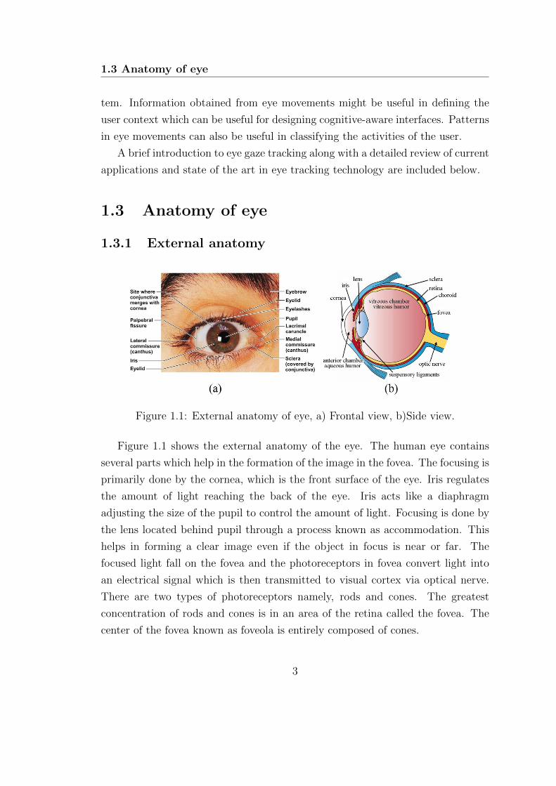
Figure 1.1: External anatomy of eye, a) Frontal view, b)Side view.
Figure 1.1 shows the external anatomy of the eye. The human eye contains
several parts which help in the formation of the image in the fovea. The focusing is
primarily done by the cornea, which is the front surface of the eye. Iris regulates
the amount of light reaching the back of the eye. Iris acts like a diaphragm
adjusting the size of the pupil to control the amount of light. Focusing is done by
the lens located behind pupil through a process known as accommodation. This
helps in forming a clear image even if the object in focus is near or far. The
focused light fall on the fovea and the photoreceptors in fovea convert light into
an electrical signal which is then transmitted to visual cortex via optical nerve.
There are two types of photoreceptors namely, rods and cones. The greatest
concentration of rods and cones is in an area of the retina called the fovea. The
center of the fovea known as foveola is entirely composed of cones.
3

Introduction
1.3.2 Imaging of eye region
Figure 1.2: Eye image captured under, a) Visible light, b) NIR lighting.
Figure 1.2 [6] shows the eye images captured in visible as well as near infrared
(NIR) lighting conditions. In visible images, the boundary between iris and sclera
is more prominent than the pupil iris boundary (also known as limbus boundary).
Most of the visible spectrum eye trackers make use of these edges for gaze tracking.
In contrast, in NIR images, pupil iris boundary is much more prominent. Most of
the commercial eye trackers leverage pupil boundary (using dark pupil method)
and glints on the eyes to estimate the gaze position. It is worth noting that
accuracy in estimating the pupil iris boundary in NIR images is much more than
determining the sclera iris boundary in visible spectrum images. However, visible
spectrum imaging has the advantage that it does not require specific hardware or
lighting arrangements and most of the smart devices are readily having a front
facing camera.
1.4 Methods for measuring eye movements
In literature, primarily four methods are used for eye tracking: scleral coil, Electro-
Oculography (EOG), Photo-Oculography (POG) or Video-Oculography (VOG),
and image-based Corneal/ Pupil reflection based method [5].
In scleral coil method, a contact lens with a mechanical or optical reference
object is worn directly on the eye. A coil is attached to the contact lens, and the
4
1.5 Image based eye gaze tracking
position of eyes can be found from the electric potential induced when placed in a
magnetic field. The scleral coil method is the most accurate method for estimating
the eye position. However, the high level of discomfort due to its invasive nature
prevents its use in practical applications. Moreover, this method determines the
position of the eye with respect to the head. Gaze estimation requires the eye
position as well as the head pose. Lack of head pose information limits its use for
point gaze estimation [7].
EOG method uses the electric potential differences of skin measured through
the electrodes placed on regions around the eye. The eye movements recorded
through EOG do not give any information about the head pose. Hence, this
modality is not suitable for point of regard estimation unless the head pose is also
available (which requires another head tracker) [8].
POG method tries to measure the features of the eye such as the shape of
pupil, limbus sclera boundary, and corneal reflections from the light source. The
variations in the appearance with eye and head movements are used to estimate
the point of regard [5].
Video or image based trackers use cameras and image processing algorithms
to find the gaze point in real-time. There are different types of video-based eye
trackers such as head mount, table mount and tower mount trackers.
Literature suggests that image-based eye tracking methods are suitable for
practical applications due to their non-intrusive and non-contact nature. The
steady increase in computational power and camera quality improve the perfor-
mance of image-based eye trackers. A brief description of different types of image-
based eye trackers is provided in the next section.
1.5 Image based eye gaze tracking
There are mainly two types of image-based eye trackers based on the illumination
source, 1) Eye trackers which use active Infrared illumination and, 2) eye trackers
using visible spectrum illumination.
Active IR illumination methods utilize bright pupil and dark pupil effects (BP-
DP) [9]. These methods are efficient and accurate methods for detection of pupil
center at low frame rates and controlled conditions. The method works on a differ-
5
Introduction
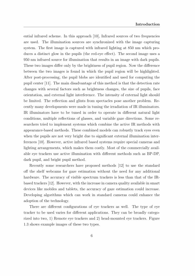
ential infrared scheme. In this approach [10], Infrared sources of two frequencies
are used. The illumination sources are synchronized with the image capturing
system. The first image is captured with infrared lighting at 850 nm which pro-
duces a distinct glow in the pupils (the red-eye effect). The second image uses a
950 nm infrared source for illumination that results in an image with dark pupils.
These two images differ only by the brightness of pupil region. Now the difference
between the two images is found in which the pupil region will be highlighted.
After post-processing, the pupil blobs are identified and used for computing the
pupil center [11]. The main disadvantage of this method is that the detection rate
changes with several factors such as brightness changes, the size of pupils, face
orientation, and external light interference. The intensity of external light should
be limited. The reflection and glints from spectacles pose another problem. Re-
cently many developments were made in tuning the irradiation of IR illuminators.
IR illuminators have to be tuned in order to operate in different natural light
conditions, multiple reflections of glasses, and variable gaze directions. Some re-
searchers tried to implement systems which combine the active IR methods with
appearance-based methods. These combined models can robustly track eyes even
when the pupils are not very bright due to significant external illumination inter-
ferences [10]. However, active infrared based systems require special cameras and
lighting arrangements, which makes them costly. Most of the commercially avail-
able eye trackers use active illumination with different methods such as BP-DP,
dark pupil, and bright pupil method.
Recently some researchers have proposed methods [12] to use the standard
off the shelf webcams for gaze estimation without the need for any additional
hardware. The accuracy of visible spectrum trackers is less than that of the IR-
based trackers [12]. However, with the increase in camera quality available in smart
devices like mobiles and tablets, the accuracy of gaze estimation could increase.
Developing algorithms which can work in standard cameras could enhance the
adoption of the technology.
There are different configurations of eye trackers as well. The type of eye
tracker to be used varies for different applications. They can be broadly catego-
rized into two, 1) Remote eye trackers and 2) head-mounted eye trackers. Figure
1.3 shows example images of these two types.
6
1.5 Image based eye gaze tracking
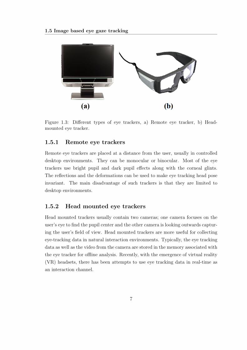
Figure 1.3: Different types of eye trackers, a) Remote eye tracker, b) Head-mounted eye tracker.
1.5.1 Remote eye trackers
Remote eye trackers are placed at a distance from the user, usually in controlled
desktop environments. They can be monocular or binocular. Most of the eye
trackers use bright pupil and dark pupil effects along with the corneal glints.
The reflections and the deformations can be used to make eye tracking head pose
invariant. The main disadvantage of such trackers is that they are limited to
desktop environments.
1.5.2 Head mounted eye trackers
Head mounted trackers usually contain two cameras; one camera focuses on the
user’s eye to find the pupil center and the other camera is looking outwards captur-
ing the user’s field of view. Head mounted trackers are more useful for collecting
eye-tracking data in natural interaction environments. Typically, the eye tracking
data as well as the video from the camera are stored in the memory associated with
the eye tracker for offline analysis. Recently, with the emergence of virtual reality
(VR) headsets, there has been attempts to use eye tracking data in real-time as
an interaction channel.
7
Introduction
1.6 Taxonomy of eye movements
Eye movements help in orienting the fovea towards the area of interest [5]. This
is achieved by several types of eye movements such as saccades, smooth pursuit,
vergence, vestibular, and nystagmus. Eye fixations also contain small movements
of eyes. A brief description of eye movement types is given below.
1.6.1 Fixations
Fixation refers to maintaining of the visual gaze on a single location. Fixations
help in gathering visual information. The typical duration of a fixation lies in the
range of 200-300 ms. A fixation contains several other miniature eye movements
like tremor, drift, and microsaccades.
1.6.2 Saccades
The brain perceives the visual field when an area is focused in fovea during fix-
ations. Changing the focus of fixation from one region to another is achieved by
a rapid movement of the eyeball known as saccades. Saccade refers to the fast
ballistic movements of eyes which help in changing the focus of visual attention.
The duration of saccades can range from 10 to 100 milliseconds [5]. Saccades are
the fastest movement any human organ can make with a peak velocity upto 900
degrees/second.
1.6.3 Smooth pursuit
Pursuit movements are generated when the eyes are following a moving object.
The velocity of eye movement is adjusted to keep the moving stimulus in the fovea.
Tracking is carried out with catch-up saccades if the velocity of the moving object
is high.
1.6.4 Vergence
Vergence is the movements of eyes in the opposite directions. Vergence movements
help in focusing the eyes on distant objects and depth perception. There are two
8
1.7 Applications of eye gaze tracking
subcategories in vergence movements they are
Divergence – The simultaneous movement of both the eyes away from each other
, and Convergence – Movement of both eyes together in the inward direction.
1.6.5 Nystagmus
These are conjugate type movements [5]. There are two types of nystagmus move-
ments: Vestibular nystagmus which compensates for the head movements and
Optokinetic nystagmus which compensate for the retinal movement of the target.
1.7 Applications of eye gaze tracking
Earlier, the uses of eye gaze tracking (EGT) were limited to scientific studies
in controlled conditions. Typical applications included the study of psychology,
ophthalmology, neurology, oculomotor characteristics and abnormalities [13], [14],
[15]. Recently there has been a surge in applications of eye gaze tracking including
human-computer interaction [9], usability studies, psychology studies, biometrics
[16], virtual reality [17], gaze-contingent displays [18], usability research, disease
diagnosis and gaming [5].
The applications of EGT can be broadly classified into two categories [5],
diagnostic and interactive. In diagnostic applications, eye gaze data is used to
estimate users visual and attention processes. Interactive applications treat eye
gaze data as an input modality to interact with machines.
Duchowski [19] divides the interactive applications into two, selective and gaze-
contingent. In selective paradigm, the eye gaze is used as a pointing device similar
to a computer mouse. Gaze-contingent paradigm describes a display system which
depends on the foveated region of the eye gaze.
Inherently, human eyes function as an input device, intended to perceive visual
stimuli. However, eye movements have certain advantages in human-computer
interaction. Eye movements are much faster than hand movements (with saccadic
peak velocities up to 900 degrees/second). The user usually looks towards the
target location before making the mechanical movement using the hands [20].
However, using eye gaze directly as a replacement for the mouse has several issues
9
Introduction
like lack of a click mechanism (Midas touch problem). Owing to these problems
researchers have found efficient methods for incorporating eye gaze along with
traditional mouse based interaction. Zhai et al. [21] introduced MAGIC, an
approach which uses both eye gaze and mouse input for a more efficient cursor
movement control. The point of gaze also gives an explicit indication of user’s
point of attention. This information can be used in HCI to identify users context
for different actions and to respond accordingly. A detailed description of mouse
warping using eye gaze can be found in [21].
The recent advancements in the areas of virtual and augmented reality can also
be benefited from eye tracking technology [17]. Humans have foveated vision where
maximum visual information is obtained from the region which is focused on the
fovea. Virtual reality headsets can use this information to render high resolution
at the locations where the user is looking [22]. This improves the perception of
the visual scene at a reduced computational load for rendering the image. Eye
movements can also be used as an interaction modality, either as a pointing device
or for eye based typing [23],[24].
The peak velocity-duration (PV-D) ratio [25] has been reported as a good in-
dicator of fatigue level. Certain patterns of eye movements known as eye accessing
cues (EAC) [26] has been known to be related to cognitive processes. Eye move-
ments are also helpful in identifying certain kinds of diseases such as nystagmus,
schizophrenia and autism [27],[28].
Assistive technology is another area where eye tracking technology can be of
much use. In motor neuron diseases like amyotrophic lateral sclerosis (ALS), eye
tracking opens the possibility to use eye movements as an interaction channel for
persons who are paralyzed [29].
1.8 Objectives and scope of the thesis
From the above discussions, it is evident that eye tracking technology can prove
to be very useful in various domains. The focus of this work is the development
of algorithms for gaze tracking and its applications. The research issues and the
objectives are outlined here.
Pupil localization is one of the most crucial stage in gaze tracking. Most of
10

1.9 Contributions of the thesis
the algorithms available in literature fail in challenging situations such as motion
blur, head movement, movement of iris towards corners, illumination variations,
and partial occlusions. Robust algorithms need to be developed for pupil local-
ization for these conditions. Methods available for gaze tracking typically use a
calibration stage. However, this cumbersome calibration stage can be avoided for
many applications where only the direction of gaze relative to the head is required.
Appearance-based methods can be developed for gaze direction classification with-
out the need of explicit calibration. There have been several attempts to use eye
movements as a biometric modality. However, the accuracy of most of the meth-
ods has not been satisfactory [16]. Information from saccades and fixations can be
used efficiently to improve the accuracy of these systems. Eye tracking data from
head-mounted eye trackers can be used for activity classification. Combining eye
movement patterns along with the visual features and head motion could be more
accurate in classifying activities.
The objectives of this work are listed below.
• Objective 1. To develop image-based algorithms for gaze tracking
– for desktop environments
– for head-mounted eye trackers with NIR (Near Infrared) illumination
• Objective 2. To develop a person-independent system for gaze direction
classification which can be used for cognitive state identification with eye
accessing cues.
• Objective 3. To develop an efficient framework for eye movement based
biometrics
• Objective 4. To develop a new framework for activity recognition using
eye tracking data and image based features
1.9 Contributions of the thesis
The contributions of this work can be outlined as:
11

Introduction
• A fast and accurate two-stage iris center localization algorithm for gaze
tracking in low-resolution video.
• A robust pupil localization algorithm for head-mounted eye trackers.
• A person independent method for gaze direction classification.
• A new framework for biometric identification using eye movements.
• A framework for egocentric activity recognition using eye movements, ego-
motion, and visual features.
1.10 Thesis organization
The organization of the thesis is given as:
• Chapter 1. Introduction
This chapter gives a brief introduction to eye tracking and its applications.
It also discusses the motivations behind the work along with objectives and
contributions.
• Chapter 2. Eye localization for gaze tracking in low-resolution
images
A framework has been developed for image based gaze tracking in desk-
top environments using an efficient iris center localization algorithm in this
chapter.
• Chapter 3. Pupil center localization algorithm for NIR images
This chapter describes the development of a robust algorithm for pupil lo-
calization in NIR images in uncontrolled conditions.
• Chapter 4. Eye gaze direction classification using Convolutional
Neural Network A convolutional neural network based approach is devel-
oped for classification of eye gaze direction which in turn helps in finding
eye accessing cues.
• Chapter 5. Eye movement-based biometric authentication A score
level fusion approach using a large set of features extracted from fixations
12

1.10 Thesis organization
and saccades for biometric authentication from eye tracking data is presented
in this chapter.
• Chapter 6. Activity recognition from head mounted eye tracker
A framework for recognition of human activities from egocentric video and
eye tracking is presented.
• Chapter 7. Conclusions and future scopes
This chapter concludes the work and discusses the future scope of the work
presented in this thesis.
13

C H A P T E R 2
Eye Localization for Gaze
Tracking in Low-Resolution
Images
This chapter presents an efficient framework developed for image based gaze
tracking in desktop environments. The challenging problem of iris center local-
ization is solved using a novel two-stage algorithm. With the proposed frame-
work, even low-cost consumer-grade webcams can be used for gaze tracking
without any additional hardware.
2.1 Introduction
Localization and tracking of the eye can be useful in face alignment, gaze tracking
and human-computer interaction [30]. The majority of the commercially available
eye trackers use active IR illumination. However, IR-based methods need extra
hardware and specifically zoomed cameras that limit the movement of the head.
Further, the accuracy of IR-based method falls drastically in uncontrolled illumi-
nation conditions. An image-based algorithm for localizing and tracking the eye
15

Eye Localization for Gaze Tracking in Low-Resolution Images
in the visible spectrum is proposed in this chapter. The main advantage of such
a method is that it does not require any additional hardware and can work with
regular low-cost webcams.
Several approaches have been reported in the literature for the detection of
iris center in low-resolution images. These methods can be broadly classified into
four categories 1) Model-based methods, 2) Feature-based methods, 3) Hybrid
methods, and 4) Learning-based methods. Model-based approaches generally ap-
proximate iris as a circle. The accuracy of such methods may deteriorate when
model assumptions are violated. In feature-based methods [30], local features like
gradient information, pixel values, corners, isophote properties, etc. are used for
the localization of iris center (IC). Hybrid methods combine both local and global
information for higher accuracy than one particular method alone. Learning-
based methods [31] try to learn representations from labeled data rather than
using heuristic assumptions.
Typically, the resolution of the front facing camera is limited in smart devices
like laptops, desktops and mobile devices. For laptops and commercially avail-
able webcams, VGA resolution (640 × 480) is a very common resolution. The
size of eye patches with this resolution is in the range of 50 × 40. We develop
the algorithms such that the performance is more than the acceptable levels for
VGA resolution and above. However, the proposed approach works for even lower
resolution images. A hybrid approach for the accurate detection and tracking of
iris center in low-resolution images is presented here. A two-stage algorithm is
proposed for localizing the IC. A novel convolution operator is derived from Cir-
cular Hough Transform (CHT) for IC localization. The new operator is efficient
in the detection of IC even in partially occluded conditions and at extreme corner
positions. Additionally, an edge-based refinement and ellipse fitting are carried
out to estimate the IC parameters accurately. IC and eye corners are used in a
regression framework to determine the point of gaze (PoG).
The important contributions from this chapter are:
• A novel hybrid convolution operator for the fast localization of iris center
• An efficient algorithm that can estimate the iris boundary in low-resolution
grayscale images
16

2.2 Related works
• A framework for the eye gaze tracking in low-resolution image sequences.
2.2 Related works
The localization of iris or pupil is an important stage in gaze tracking. Once the
iris center has been successfully localized, regression-based methods can be used
for finding the corresponding gaze points on the screen. Most of the passive image-
based methods treat iris localization as a circle detection problem. Circular Hough
Transform (CHT) is a standard method used for detection of circles [32]. Young
et al. [33] reported a method for the detection of iris using specialized Hough
transform and tracking using active contour algorithm. However, this method
requires high-quality images obtained from a head mounted camera.
Smereka et al. [34] presented a modified method for the detection of circular
objects. They used the votes from each sector along with the gradient direction to
detect circle locations. Atherton et al. [35] proposed phase combined orientation
annulus (PCOA) method for the detection of circles with convolutional operators.
The annulus is convolved with the edge image to detect the peaks. Peng Yang
et al. [36] presented an algorithm for first localizing the eye region with Gabor
filters and then localizing the pupil with a radial symmetry measure. However,
the accuracy of the method falls when the iris moves to corners. Valenti et al.
proposed [37] an isophote property based iris centre localisation algorithm. The
illumination invariance of isophote curves along with gradient voting is used for the
accurate detection of iris centers. This method is further extended in [38] for scale
invariance using scale-space pyramids. The face pose and iris center obtained are
combined to determine the point of gaze (PoG) achieving an average accuracy of
2-5 degrees in unconstrained situations. The accuracy of the method deteriorates
when iris moves towards the corners resulting in false detection of eyebrows and
eye corners as iris centers. Timm et al. [39] proposed a method using gradients
of the eye region. An extensive search is carried out in all pixels maximizing the
inner product of the normalized gradient and normalized distance vector. IC is
obtained as the maximum of weighted function in the region of interest. The time
taken for search increases with increase in the search area. The performance of the
algorithm degrades in noisy and low-resolution images where the edge detection
17

Eye Localization for Gaze Tracking in Low-Resolution Images
method fails.
D’Orazio et al. [40] have reported a method for detection of iris centre us-
ing convolution kernels. The kernels are convolved with the gradient of images
and peak points are selected as candidates. The mean absolute error (MAE)
similarity measure is used to reject false positive cases. Daugman [41] proposed
an integro-differential operator (IDO) for the accurate localization of iris in IR
images. Curve integral of gradient magnitudes is computed to extract the iris
boundary. Recently Baek et al. [42] presented an eyeball model based method for
gaze tracking. Elliptical shapes for eye model is saved in the database and used at
the time of detection for finding the iris centers. A combined IDO and a weighted
combination of features are used for the localization of iris center. Polynomial
regression methods were used for training the system. They obtained average
accuracy of 2.42 degrees visual angles. Sewell and Komogortsev [43] developed
an artificial neural network based method for gaze estimation from low-resolution
webcam images. They trained the neural network directly with the pixel values of
the detected eye region. They obtained an average accuracy of 3.68 degrees. Zhou
et al. [44] proposed a generalized projection function (GPF) that uses various
projection functions and a special case hybrid projection function for localizing
the iris center. The peak positions of vertical and horizontal GPF were used to
localize the eye. Bhaskar et al. [45] proposed a method for identifying and track-
ing blinks in video sequences. Candidate eye regions are identified using frame
differencing and are subsequently tracked using optical flow. The direction and
magnitude of the flow are used to determine the presence of blinks. They ob-
tained an accuracy of 97% in blink detection. Wang et al. [46] proposed one-circle
method where the detected iris boundary contours are fitted with an ellipse and
back projected to find the gaze points. Recently many learning based methods
have been proposed for iris center localization and gaze tracking. Marku et al. [47]
proposed a method for localising pupil in images using an ensemble of randomized
trees. They used a standard face detector to localize face and eye regions. En-
semble of randomized trees model was trained using the eye regions and ground
truth locations. Their method obtained good accuracy in BioID database. How-
ever, the accuracy of gaze estimation was not discussed in their work. Zhang
et al. [31] proposed an appearance based gaze estimation framework based on
18
2.2 Related works
Convolutional Neural Network (CNN). They trained a CNN model with a large
amount of data collected in real-world conditions. Normalized face images and
the head poses obtained from a face detector were used as the input to the CNN
to estimate the gaze direction. They obtained good accuracy in person and pose
independent scenarios. However, the accuracy for person dependent case is lower
than current geometric model based methods. The accuracy might increase with
larger amount of training data, but the time taken for on-line data collection and
training becomes prohibitive. Schneider et al. [48] proposed a manifold alignment
based method for appearance based person independent gaze estimation. From
the registered eye images, a wide variety of feature extraction methods like LBP
histogram, HoG, mHoG and DCT coefficients were extracted. A combination of
LBP and mHOG based features obtained the best performance. Several regression
methods were used for appearance based gaze estimation. Sub-manifolds for each
individual were obtained using the ground truth gaze locations. Synchronized
delaunay sub-manifold embedding (SDSE) method was used to align the mani-
folds of different persons. Even though their method achieved better performance
compared to other appearance-based regression methods, the effect of head pose
variations on the accuracy was not discussed.
Sugano et al. [49] proposed a person and head pose independent method for
appearance based gaze estimation. They captured the images of different persons
using a calibrated camera, and images corresponding to various head poses were
synthesized. An extension of random forest algorithm was used for training. The
appearance of eye region and the head pose was used as the input to the algorithm
which learns a mapping to the 3D gaze direction.
Most of the methods proposed in literature fail when iris moves towards the
corners. Another problem is regarding eye blinks, most of the algorithms return
false positives when the eyes are closed. A stable reference point is required
along with the IC location for PoG estimation. Learning-based methods require
large amounts of labeled data for satisfactory performance. The performance of
such methods also deteriorates when imaging conditions are different. Training
for person dependent models require huge amount of data and often require a
considerable amount of time. This limits the deployment of such methods in
mobiles, tablets, etc.
19
Eye Localization for Gaze Tracking in Low-Resolution Images
In the proposed method, IC can be accurately localized even in extreme corner
locations using the ellipse approximation. The computatitional load is reduced
using the two-stage scheme. Further, an eye closure detection stage is added to
prevent false positives. The localization error can be minimized by tracking the
IC in the subsequent frames. The estimated IC is used in a regression framework
to estimate the PoG.
2.3 Proposed algorithm
Different stages of the proposed framework are described here.
2.3.1 Face detection and eye region localization
Knowledge of the position and pose of the face is an essential factor in deter-
mining the point of gaze. Detection and tracking of the face help in obtaining
candidate regions for eye detection. This reduces the false positive rate as well as
computation time. Haar-like feature based method [50] is used for face detection
because of its higher accuracy and faster execution. An improved implementa-
tion of face detection and tracking has been proposed in our earlier work [51]
(shown in Appendix A). The modified algorithm can detect in-plane rotated im-
ages using affine transform based algorithm. The computation is carried out in
the down sampled images to make the detection faster. The search space of de-
tection algorithm is dynamically constrained based on the temporal information,
which further increases the speed of face detection. Kalman filter-based tracking
is used to predict the location of the face when it is not detected. This also helps
in minimizing false detections. The de-rotated eye region obtained is used in sub-
sequent stages. This makes the performance of the algorithm invariant to in-plane
rotations. The purpose of the de-rotation stage is only to provide a de-rotated
region of interest (ROI) for the further processing stages. The accuracy of face
rotation estimation in the pre-processing stage is only up to 15 degrees. More
accurate in-plane face rotation is obtained in the later stage using the angle of the
line connecting the inner eye corners. With the improved face-tracking scheme,
the frame rates of processing increase greatly (up to 200 frames per second). The
20
2.3 Proposed algorithm
analysis and tradeoffs of the algorithm has been presented in [51].
2.3.2 Iris center localization
The method proposed here use a coarse to fine approach for detecting the accurate
center of the iris. The two-stage approach reduces the computational requirement
as well as false detection rate. The outputs of various stages in IC localization are
shown in Fig. 2.1.
2.3.2.1 Coarse iris center detection
In this stage, iris detection is formulated as circular disc detection. An average
ratio between the width of face and iris radius was obtained empirically. For a
particular image, the range of the radius is computed using this ratio and width
of the detected face. The image gradient of iris boundary points will always
be pointing outwards. The gradient directions and intensity information is used
for the detection of eyes. The gradients of the image are invariant to uniform
illumination changes.
A novel convolution operator is proposed to detect peak location corresponding
to the center of the circle. A class of convolution kernels, known as Hough Trans-
form Filters [35] are used for this purpose. In CHT filter, the 3D accumulator is
collapsed to a 2D surface by selecting a range of the radii.
The 2D accumulator can be calculated efficiently using a convolution opera-
tor. Thus a CHT filter is derived, which acts directly upon the image without
any requirement of edge detection. A vector convolution kernel is designed for
correlating with the gradient image, which gives a peak at the center of the iris.
The convolution operator is designed as a complex operator with magnitude
unity. The operator detects a range of circles by taking dot products with ori-
entations inside the radius range. The equation is similar to orientation annulus
proposed by Atherton et al. [35]. The equation of convolution kernel is given as
21

Eye Localization for Gaze Tracking in Low-Resolution Images
Figure 2.1: Stages in ellipse fitting: (a) Cropped eye region, (b) Correlation surfacefrom the proposed operator, (c) Selected candidate boundary points, (d) Fittedellipse.
OCOA (m,n) =
{cos θmn+i sin θmn√
m2+n2 , iff, R2min < m2 + n2 < R2
max
0, otherwise(2.1)
where,
θmn = tan−1 (n/m) (2.2)
Where m and n denote the coordinates of the kernel matrix with respect to the
origin. The operator is scaled for equal contributions of circles in the radius range.
A weighting matrix kernel (WA) is also used for finding regions with maximum
dark values
WA (m,n) =
{1√
m2+n2 , iff,m2 + n2 < R2
max
0, otherwise(2.3)
The gradient complex orientation annulus is given as,
CGCOA = Re (OCOA)⊗ Sx + iIm (OCOA)⊗ Sy (2.4)
Where ⊗ denotes the convolution operator; Sx and Sy denote the 3× 3 Schaar
kernels in x and y directions respectively. Schaar differential kernel is used owing
to its mathematical properties in gradient estimation. In most of the cases, the
upper portion of the iris is occluded by eyelids. An additional weighing factor (β)
is included to increase the contribution of horizontal gradients. The convolution
22
2.3 Proposed algorithm
kernel can be made real-valued as
CRCC = βRe (OCOA)⊗ Sx +1
βIm (OCOA)⊗ Sy (2.5)
Where β denotes the weighting factor. The average intensity of each point
in image can be obtained by convolving the weighting kernel with the negated
version of the image as,
W = (255− I)⊗WA (2.6)
Where I and WA denote the image and the kernel for computing the intensity
component respectively. The final correlation output (CO) can be obtained by
combining the convolution results for both gradient and intensity kernels as,
CO = λ (I ⊗ CRCC) + (1− λ)W (2.7)
Where, λ ∈ [0, 1] is a scalar used to obtain the weighted combination of gra-
dient information and image intensity to reduce spurious detections. Iris center
corresponds to the maximum of the correlation surface CO. Further, it is possible
to represent all these operations with a single real convolution kernel, which can
be applied on the image without any pre-processing, making the iris center local-
ization procedure even faster. For bigger circles, convolution can be carried out
in Fourier domain for enhancing the speed of the computation.
The peak of correlation output alone may lead to false detections in partially
occluded images. Here, peak to side lobe ratio (PSR) of the points are used to find
the iris location. The PSR values calculated in each of the local maxima and the
point with maximum PSR is considered as the iris center. The PSR is estimated
as:
PSR =
(COmax − µ
σ
)(2.8)
Where COmax is the local maxima in the correlation output, µ and σ are the
mean and standard deviation in the window around the local maxima. We have
used a window size of 11× 11 in this work. The point with the maximum PSR is
selected as the iris center.
23
Eye Localization for Gaze Tracking in Low-Resolution Images
2.3.2.2 Sub-pixel edge refining and ellipse fitting
In this stage, the approximate center points obtained in the previous stage are
used to refine the IC location. The objective is to fit the iris boundary with an
ellipse. The constraints on the major and minor axis can be obtained empirically
( Rmin and Rmax ). The algorithm presented searches in the radial direction
similar to Starburst algorithm [52]. However, the search process finds only the
strongest edges with similar gradients. Dominant edges with agreeing directions
are selected with sub-pixel accuracy. An angle versus distance plot is obtained,
and the outlier points are filtered using median filter. An ellipse can be fitted to
five points by the least square method using Fitzgibbon’s algorithm [53]. However,
we used this algorithm in a random sample consensus (RANSAC) framework for
minimizing the effect of outliers. RANSAC algorithm is employed [54] for ellipse
fitting, using the gradient agreement [55] of the detected boundary points and
the fitted ellipse as the support function. Additionally, a modified goodness of
fit (GoF) is evaluated as the integral of dot products of outward gradients over
the detected boundary (only agreeing gradients). The parameters obtained are
considered as false positives if the goodness of fit is less than a threshold. The
detailed algorithm for ellipse fitting is given in Algorithm 1.
GoF =∑
x,y∈f(λ)
(min
(∇f(x, y)
|∇f(x, y)|• ∇I(x, y), 0
))(2.9)
where, f(λ) and ∇f(x, y) denote the fitted ellipse and its derivative respec-
tively. ∇I(x, y) denotes the image derivative at position (x, y), belonging to the
fitted ellipse.
2.3.3 Iris tracking
A Kalman filter (KF) [56] is used to track the IC in a video sequence. The search
region for iris detection can be localized with the tracking approach. Once the
IC is detected with sufficient confidence, the point can be tracked in subsequent
frames using the dynamics of eye motion. Face detection stage can be avoided in
this case. The KF [57] estimates can be used as the corrected estimates for iris
position. It is to be noted that the objective here is not to model the dynamics
24

2.3 Proposed algorithm
of saccade, but to get a smoother estimate of IC location, which can be useful for
reducing search region for IC localization in next frame.
Algorithm 1 Algorithm for iris boundary refinement
Input: The grayscale eye region I and the estimated centres O = (cx, cy)
Output: Fitted ellipse parameters λ = (cx, cy, a, b, ψ)
1: Initialize : CandidatePoints= NULL
2: tempBest=[0,0]
3: for θ ← 0 to 2π do
4: for r ← Rmin to Rmax do
5: Pt = (cx + r cos θ, cy + r sin θ)
6: Calculate the gradients and magnitude at the points
7: ~g = Gxx+Gy y
‖G‖
8: if ‖g‖ < threshold then
9: Break
10: else
11: ~r = r cos θx+ r sin θy
12: Calculate the dot product of normalized gradient vector
13: if cos θ = ~r • ~g > threshold then
14: if tempbestmag < Pt.mag, P t.angle then
15: temp best = Pt
16: tempbestmag = [cos θ, ‖g‖]17: else
18: Continue
19: end if
20: end if
21: end if
22: end for
23: CandidatePoints.append(temp best)
24: end for
25: Filter the detected points with angular median filter
26: Fit Ellipse with RANSAC algorithm
27: Return the parameters of ellipse: λ← (cx, cy, a, b, ψ)
25
Eye Localization for Gaze Tracking in Low-Resolution Images
In the current tracking application, constant velocity model is chosen as the
transition model. Coordinates of the center of iris along with their velocities are
used as states.
Xk+1 = FkXk +Wk (2.10)
Where, Xk is the state containing x, y, vx, vy (coordinates and velocities in x
and y directions respectively) at the kth instant. The measurement noise covari-
ance matrix is computed from the measurements obtained during the gaze calibra-
tion stage. The process covariance matrix is computed empirically. Measurements
obtained from the IC detector are used to correct the estimated states.
2.3.4 Eye closure detection
The IC localization algorithm may return false positives when the eyes are closed.
Thresholds on the peak magnitude were used to reject false positives. However,
the quality of peak may degrade in conditions such as low contrast, image noise,
and motion blur. The accuracy of the algorithm may fall in these conditions, and
hence a machine learning based approach is used to classify the eye states as open
or close. The Histogram of oriented gradients (HOG) [58] features of eye regions
are calculated and a support vector machine (SVM) based classifier is constructed
to predict the state of the eye. The HOG features are computed in the detected
ROI for left and right eyes separately. The SVM classifier was trained offline from
the database. If the eye state is classified as closed, then the predicted value from
KF is used as the tentative position of the eye. If eyes are detected as open, then
the result from the two-stage method is used to update the KF.
2.3.5 Eye corner detection and tracking
The appearance of inner eye corner exhibits insignificant variations with eye move-
ments and blinks. Therefore, we propose to use inner eye corners as reference
points for gaze tracking. The eye corners can be located easily in the eye ROI.
The vectors connecting eye corners and iris centers can be used to calculate gaze
position. Several methods have been proposed in the literature for the localization
26
2.3 Proposed algorithm
of facial landmarks [59]. In the proposed method, Gabor jets [60] are used to find
eye corners in the eye ROI owing to its high accuracy. The detected eye corners
are tracked in the subsequent frames using optical flow and normalized cross cor-
relation (NCC) [61], [62] based method. The tracker is automatically reinitialized
if the correlation score is less than a pre-set value.
2.3.6 Gaze estimation
Gaze point can be computed from the IC location and a reference point. Earlier
works [63], [64] have used the eye centre and corneal reflections as reference points.
False detection in any of the corners will result in performance degradation of the
algorithm. Hence, the inner eye corners are used as reference points in this work.
Detection of the eye corner in every frame might increase the error rates and
computational load. We avoid this issue by tracking of eye corners in the frames
which ensure stable reference points. If (x1, y1) and (x2, y2) denote the coordinates
of eye corner and iris centre respectively, the eye corner-iris center (EC-IC) vector
can be obtained as: (x, y) = (x2−x1, y2− y1) (with reference to the corner). The
EC-IC vector is calculated separately for the left and right eye.
2.3.6.1 Calibration
In the calibration stage, subjects were asked to look at uniformly distributed
positions on the screen. The EC-IC vectors along with gaze points are recorded.
The mapping between EC-IC vector and screen coordinates is nonlinear because
of the angular movement of the iris. We used two different models for the mapping
between EC-IC vector and point of gaze (PoG), 1) polynomial regression and 2)
a radial basis function (RBF) kernel based method. In polynomial regression, a
second order regression model is used for determining the point of gaze since it
offers the best trade-off between model complexity and accuracy.
screenXi = a0xi + a1yi + a2xiyi + a3x2i + a4y
2i + a5 (2.11)
screenYi = b0xi + b1yi + b2xiyi + b3x2i + b4y
2i + b5 (2.12)
Where, (xi, yi) are the components of EC-IC vector and, (screenXi, screenYi)
27
Eye Localization for Gaze Tracking in Low-Resolution Images
the corresponding screen positions. The data obtained from calibration stage is
used in the least square regression framework to calculate unknown parameters.
In the RBF kernel based method, we used non-parametric regression [65] for
estimating PoG. The components of EC-IC vector are transformed into kernel
space using the following expression,
k(pi, pl) = exp(−‖pi − pl‖2
2σk2) (2.13)
Where, pi and pl denote of EC-IC vector and the landmark points respectively.
σk denote the standard deviation of the RBF function. We have tested the algo-
rithm in both 3 × 3 and 4 × 4 calibration grids. Instead of using all the samples
as landmark points, we have used only one landmark per calibration point. The
number of landmarks used was 9 and 16 for 3 × 3 and 4 × 4 grids respectively.
For each calibration point on the grid, the landmark vector is calculated as the
median of the components of EC-IC vector at the particular point. The dimen-
sion of the design matrix is reduced by the use of landmark points (since the data
points are clustered around the calibration points). Regression is carried out after
transforming all the points to kernel space [66] which improved the accuracy of
PoG estimation. The training procedure is carried out for left and right eyes.
2.3.6.2 Estimation of PoG
The parameters obtained from calibration procedure are used to determine the
gaze position. The regression function obtained is used to map the EC-IC vectors
to screen coordinates. The gaze position is computed as the average position
returned by the left and right eye models. The head position is assumed to be
stable during the calibration stage. After calibration, the estimated gaze point
will be on the calibration plane (i.e., w.r.t the position of the face during the
calibration stage). Deviation from this face position would cause errors in the
estimated gaze locations. The effect of 2D translation is minimal for moderate
head movements since the reference points for EC-IC vector are eye corners, which
also move along with face (thereby providing a stable reference invariant to 2d
translational motion). Even though the method is invariant to moderate amount
28
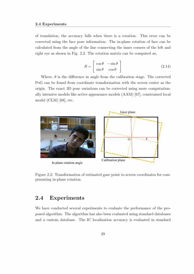
2.4 Experiments
of translation, the accuracy falls when there is a rotation. This error can be
corrected using the face pose information. The in-plane rotation of face can be
calculated from the angle of the line connecting the inner corners of the left and
right eye as shown in Fig. 2.2. The rotation matrix can be computed as,
R =
[cos θ − sin θ
sin θ cos θ
](2.14)
Where, θ is the difference in angle from the calibration stage. The corrected
PoG can be found from coordinate transformation with the screen center as the
origin. The exact 3D pose variations can be corrected using more computation-
ally intensive models like active appearance models (AAM) [67], constrained local
model (CLM) [68], etc.
Figure 2.2: Transformation of estimated gaze point to screen coordinates for com-pensating in-plane rotation.
2.4 Experiments
We have conducted several experiments to evaluate the performance of the pro-
posed algorithm. The algorithm has also been evaluated using standard databases
and a custom database. The IC localization accuracy is evaluated in standard
29

Eye Localization for Gaze Tracking in Low-Resolution Images
databases and compared with the state of the art methods. The accuracy in PoG
estimation and eye closure detection is assessed in the custom dataset.
2.4.1 Experiments on IC localization
2.4.1.1 Evaluation method
Face detection is carried out using Viola-Jones method [69]. The eye regions are
localized based on anthropometric ratios.
The normalized error is used as the metric for comparison with other algo-
rithms. The normalized measure for worst eye characteristics (WEC) [70] is de-
fined as
eWEC =max(dl, dr)
w(2.15)
Where dl and dr are the Euclidean distances between ground truth and detected
iris centres (in pixels) of left and right eye respectively, and w is the true distance
between the eyes in pixels. The average (AEC) and best of eye detection (BEC)
errors are also calculated for comparison. They are defined as:
eAEC =(dl + dr)
2w, eBEC =
min(dl, dr)
w(2.16)
Where, eBEC is the minimum error in both the eyes and eAEC is the average
error of both the eyes.
2.4.1.2 Experiments in BioID and Gi4E Databases
A comparison of the proposed method with the state of the art methods is carried
out for BioID [71] and Gi4E [72] databases. The BioID database consists of images
of 23 individuals taken at different times of the day. The size, position, and pose of
the faces change in the image sequences. The contrast is very low in some images.
In some images, eyes are closed. There are images where subject wearing glasses
and glints are present due to illumination variations. The database contains a
total of 1,521 images with a resolution of 384× 288 pixels. The ground truth files
for left and right iris centers are also available.
Gi4E dataset consists of 1380 color images of 103 subjects with a resolution
30
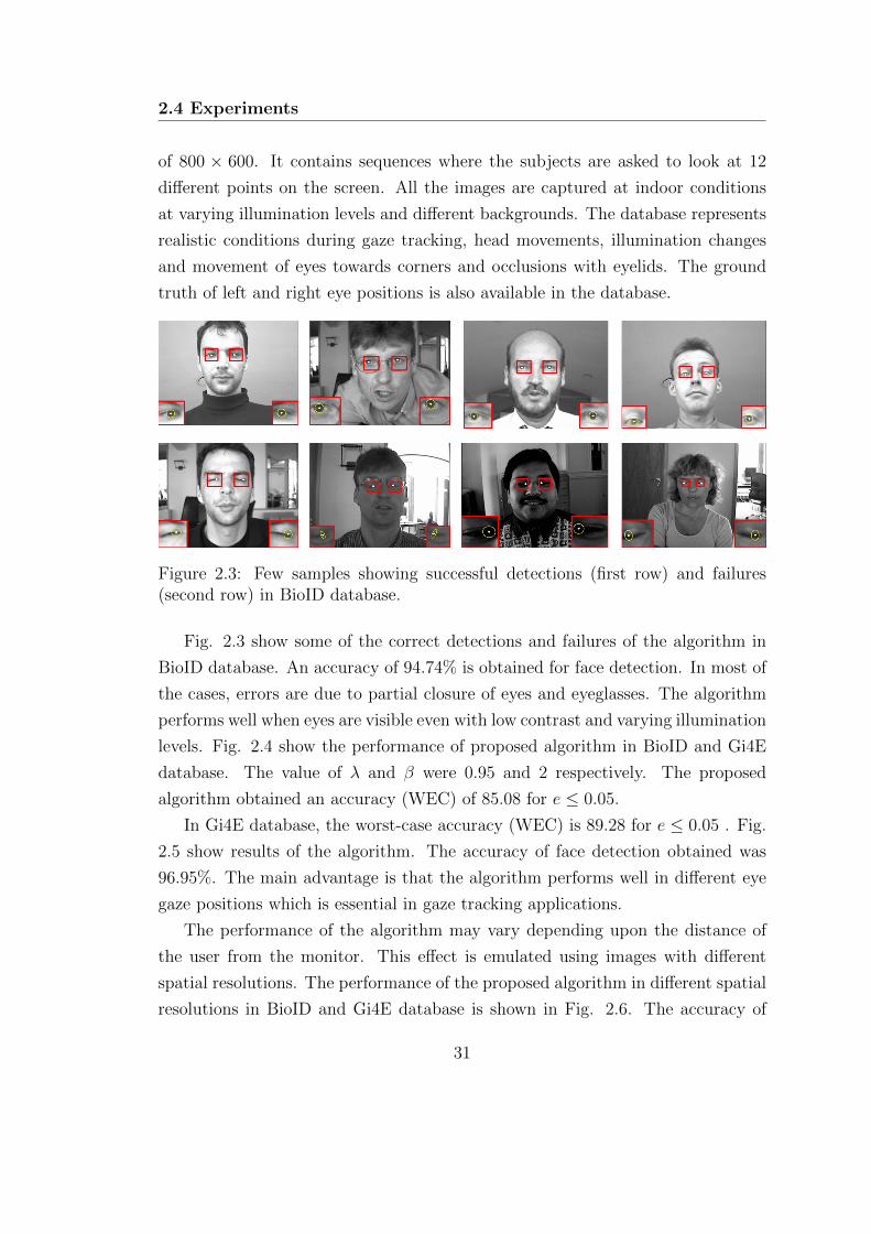
2.4 Experiments
of 800 × 600. It contains sequences where the subjects are asked to look at 12
different points on the screen. All the images are captured at indoor conditions
at varying illumination levels and different backgrounds. The database represents
realistic conditions during gaze tracking, head movements, illumination changes
and movement of eyes towards corners and occlusions with eyelids. The ground
truth of left and right eye positions is also available in the database.
Figure 2.3: Few samples showing successful detections (first row) and failures(second row) in BioID database.
Fig. 2.3 show some of the correct detections and failures of the algorithm in
BioID database. An accuracy of 94.74% is obtained for face detection. In most of
the cases, errors are due to partial closure of eyes and eyeglasses. The algorithm
performs well when eyes are visible even with low contrast and varying illumination
levels. Fig. 2.4 show the performance of proposed algorithm in BioID and Gi4E
database. The value of λ and β were 0.95 and 2 respectively. The proposed
algorithm obtained an accuracy (WEC) of 85.08 for e ≤ 0.05.
In Gi4E database, the worst-case accuracy (WEC) is 89.28 for e ≤ 0.05 . Fig.
2.5 show results of the algorithm. The accuracy of face detection obtained was
96.95%. The main advantage is that the algorithm performs well in different eye
gaze positions which is essential in gaze tracking applications.
The performance of the algorithm may vary depending upon the distance of
the user from the monitor. This effect is emulated using images with different
spatial resolutions. The performance of the proposed algorithm in different spatial
resolutions in BioID and Gi4E database is shown in Fig. 2.6. The accuracy of
31
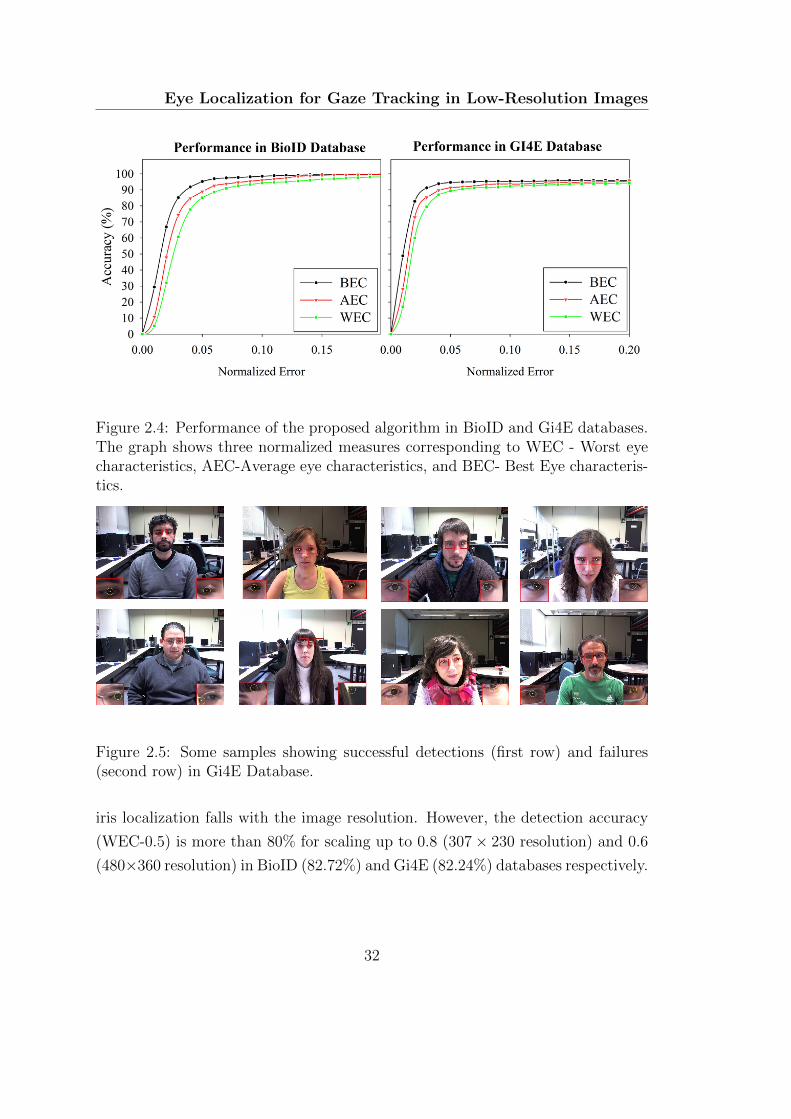
Eye Localization for Gaze Tracking in Low-Resolution Images
Figure 2.4: Performance of the proposed algorithm in BioID and Gi4E databases.The graph shows three normalized measures corresponding to WEC - Worst eyecharacteristics, AEC-Average eye characteristics, and BEC- Best Eye characteris-tics.
Figure 2.5: Some samples showing successful detections (first row) and failures(second row) in Gi4E Database.
iris localization falls with the image resolution. However, the detection accuracy
(WEC-0.5) is more than 80% for scaling up to 0.8 (307× 230 resolution) and 0.6
(480×360 resolution) in BioID (82.72%) and Gi4E (82.24%) databases respectively.
32
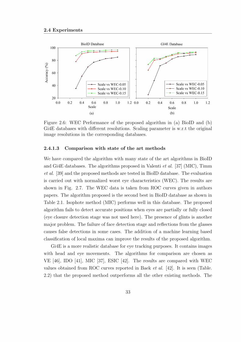
2.4 Experiments
Figure 2.6: WEC Performance of the proposed algorithm in (a) BioID and (b)Gi4E databases with different resolutions. Scaling parameter is w.r.t the originalimage resolutions in the corresponding databases.
2.4.1.3 Comparison with state of the art methods
We have compared the algorithm with many state of the art algorithms in BioID
and Gi4E databases. The algorithms proposed in Valenti et al. [37] (MIC), Timm
et al. [39] and the proposed methods are tested in BioID database. The evaluation
is carried out with normalized worst eye characteristics (WEC). The results are
shown in Fig. 2.7. The WEC data is taken from ROC curves given in authors
papers. The algorithm proposed is the second best in BioID database as shown in
Table 2.1. Isophote method (MIC) performs well in this database. The proposed
algorithm fails to detect accurate positions when eyes are partially or fully closed
(eye closure detection stage was not used here). The presence of glints is another
major problem. The failure of face detection stage and reflections from the glasses
causes false detections in some cases. The addition of a machine learning based
classification of local maxima can improve the results of the proposed algorithm.
Gi4E is a more realistic database for eye tracking purposes. It contains images
with head and eye movements. The algorithms for comparison are chosen as
VE [46], IDO [41], MIC [37], ESIC [42]. The results are compared with WEC
values obtained from ROC curves reported in Baek et al. [42]. It is seen (Table.
2.2) that the proposed method outperforms all the other existing methods. The
33

Eye Localization for Gaze Tracking in Low-Resolution Images
accuracy of MIC method is very low when the eyes move to the corners. The circle
approximation of most of the algorithms fails when eyes move towards the corners,
making them inapt for eye gaze tracking applications. The performance evaluation
is carried out on each frame separately. Addition of temporal information using
Kalman filter can increase the accuracy of the algorithm greatly.
Figure 2.7: WEC performance comparison of proposed method with state of theart methods in Gi4E and BioID databases.
Table 2.1: Comparison of proposed method with state of the art algorithms in
BioID database
Method e ≤ 0.05 e ≤ 0.10 e ≤ 0.15 e ≤ 0.20
MIC[37]+Sift kNN 86.09 91.67 94.5* 96.9*
Proposed 85.08 94.3 96.67 98.13
Timm et al. [39] 82.5 93.4 95.2 96.4
*approximated from graph [37]
34
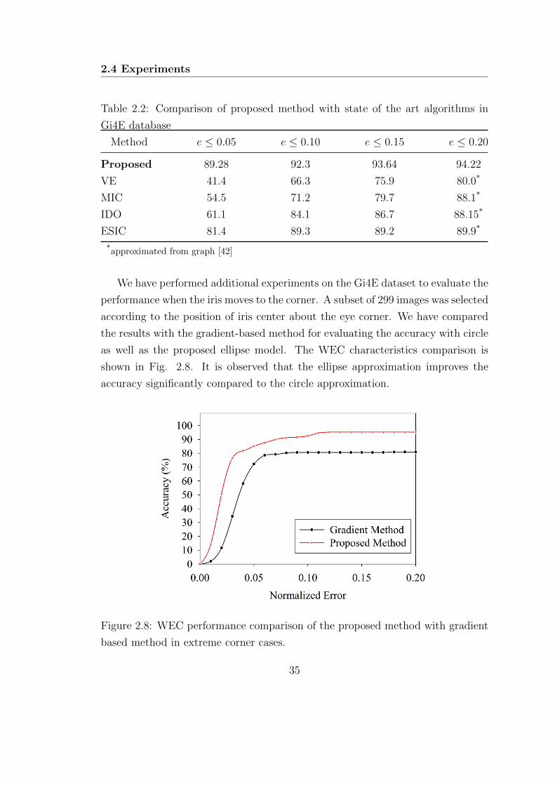
2.4 Experiments
Table 2.2: Comparison of proposed method with state of the art algorithms in
Gi4E database
Method e ≤ 0.05 e ≤ 0.10 e ≤ 0.15 e ≤ 0.20
Proposed 89.28 92.3 93.64 94.22
VE 41.4 66.3 75.9 80.0*
MIC 54.5 71.2 79.7 88.1*
IDO 61.1 84.1 86.7 88.15*
ESIC 81.4 89.3 89.2 89.9*
*approximated from graph [42]
We have performed additional experiments on the Gi4E dataset to evaluate the
performance when the iris moves to the corner. A subset of 299 images was selected
according to the position of iris center about the eye corner. We have compared
the results with the gradient-based method for evaluating the accuracy with circle
as well as the proposed ellipse model. The WEC characteristics comparison is
shown in Fig. 2.8. It is observed that the ellipse approximation improves the
accuracy significantly compared to the circle approximation.
Figure 2.8: WEC performance comparison of the proposed method with gradient
based method in extreme corner cases.
35

Eye Localization for Gaze Tracking in Low-Resolution Images
2.4.2 Experiment with our database
2.4.2.1 Evaluation of gaze estimation accuracy
An experiment was performed on ten subjects using a standard webcam and a
15.6- inch monitor with a resolution of 1366 × 768. The subjects were seated 60
cm from the screen and asked to follow the red dot on the monitor. The videos
of the eye movements were recorded at 30 fps at a resolution of 640 × 480. The
subjects were asked to look at the calibration patterns two times. We used both
9 point and 16 point calibration and compared the results. Fig. 2.9 shows some
of the images from the dataset.
We have evaluated the IC localization accuracy on a subset of images in the
in-house dataset. A subset of 1000 images was selected, and the IC localization
accuracy was evaluated. Some of the sample detections are shown in Fig. 2.10.
The proposed approach obtained WEC accuracy of 90.2% and 92.9% for e ≤ 0.05
and e ≤ 0.10 respectively.
For 3×3 and 4×4 calibration grids, we have tested with polynomial regression
and kernel space-based methods. The samples from the first session were used in
the training stage. The parameters for regression were found from the training
data. In testing stage, the samples in the second session were used to estimate
the PoG. The mean position computed from the left and right eye PoG is used
as the final gaze point. The error in the estimation is computed using the ground
truth. The mean absolute error in visual angles in horizontal, vertical and overall
accuracy is computed using the head distance from the screen.
Accuracy = tan−1 (error/head distance) (2.17)
The average errors are high when the EC-IC vectors are computed on a frame
by frame basis. We further computed the PoG using KF estimates which reduced
the jitter significantly. The results with and without KF on 3× 3 and 4× 4 cali-
bration grids are tabulated in Table 2.3. The qualitative results of gaze estimation
stage are shown in Fig. 2.11.
36

2.4 Experiments
Tab
le2.
3:G
aze
esti
mat
ion
erro
r
Raw
gaze
pos
itio
nW
ith
Kal
man
Filte
r
Met
hod
Cal
ibra
tion
Poi
nts
MA
E(d
egre
es)
MH
E(d
egre
es)
MV
E(d
egre
es)
MA
E(d
egre
es)
MH
E(d
egre
es)
MV
E(d
egre
es)
Pol
ynom
ial
93.
461.
052.
362.
030.
671.
3616
2.97
0.98
2.01
1.95
0.62
1.32
RB
FK
ernel
σk
=5
92.
810.
931.
911.
530.
471.
0516
2.71
0.87
1.83
1.33
0.40
0.91
ME
A-M
ean
Abso
lute
Err
or;
MH
E-M
ean
Hor
izon
tal
Err
or;
MV
E-M
ean
Ver
tica
lE
rror
37
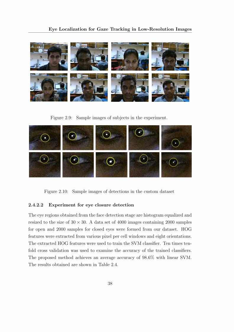
Eye Localization for Gaze Tracking in Low-Resolution Images
Figure 2.9: Sample images of subjects in the experiment.
Figure 2.10: Sample images of detections in the custom dataset
2.4.2.2 Experiment for eye closure detection
The eye regions obtained from the face detection stage are histogram equalized and
resized to the size of 30× 30. A data set of 4000 images containing 2000 samples
for open and 2000 samples for closed eyes were formed from our dataset. HOG
features were extracted from various pixel per cell windows and eight orientations.
The extracted HOG features were used to train the SVM classifier. Ten times ten-
fold cross validation was used to examine the accuracy of the trained classifiers.
The proposed method achieves an average accuracy of 98.6% with linear SVM.
The results obtained are shown in Table 2.4.
38
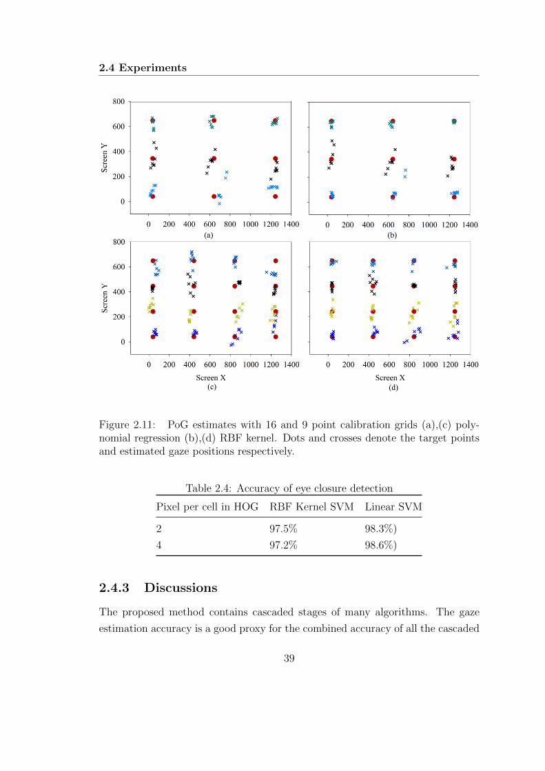
2.4 Experiments
Figure 2.11: PoG estimates with 16 and 9 point calibration grids (a),(c) poly-nomial regression (b),(d) RBF kernel. Dots and crosses denote the target pointsand estimated gaze positions respectively.
Table 2.4: Accuracy of eye closure detection
Pixel per cell in HOG RBF Kernel SVM Linear SVM
2 97.5% 98.3%)
4 97.2% 98.6%)
2.4.3 Discussions
The proposed method contains cascaded stages of many algorithms. The gaze
estimation accuracy is a good proxy for the combined accuracy of all the cascaded
39

Eye Localization for Gaze Tracking in Low-Resolution Images
stages. Face and IC are tracked using Kalman filters independently due to their
distinct dynamics. The tracking based framework increases the robustness by
reducing the effect of per-frame localization errors.
For successful eye tracking using webcams, the normalized error should be
less than 0.05. The proposed algorithm performs better in realistic conditions for
webcam-based gaze tracking. The accuracy of gaze estimation was evaluated with
the proposed approach in both 3 × 3 and 4 × 4 calibration grids. RBF kernel-
based non-parametric regression method was found to perform better than second
order polynomial models. The average error rate obtained with the per-frame
based detection was 2.71 degrees. The accuracy of the gaze tracking improved
significantly by the use of KF, which uses the temporal information effectively to
reduce the error rate to 1.33 degrees.
The main strength of the proposed algorithm is in the two stage abstraction.
We approximate the iris with an ellipse. However, time consuming search in a
five parameter space is obviated using the two stage approach. One of the main
contribution is the simplification of the ellipse fitting problem with a rather simple
two stage scheme using appropriate constraints obtained from the face detection
stage. Another advantage here is that small errors in the first stage can be refined
in the second stage. Further, the addition of the tracking framework makes the
algorithm more robust.
One of the advantages of the proposed algorithm is the low computational
load. The eye detection, being a convolution-based method can be implemented
in Fourier domain [73] for faster computation. Multi-resolution convolution can be
used to reduce the search space even further. The algorithm was implemented in a
2.5 GHz core 2 Duo desktop computer with 2 GB RAM. The C++ implementation
using OpenCV library [74] (without multi-threading) was used for the evaluation
experiments in Ubuntu 14.04 OS (32 bit) environment. It detects the face and
eye corners in the first frame and tracks the eye corners over time. The temporal
information is used to reduce the search space for face detection using a Kalman
filter. The images were acquired using a 60 fps, 640 × 480 webcam. The online
processing speed was limited only by the lower frame rate of the camera. The
offline processing speed of the entire algorithm is well over 100 fps on the recorded
video. This is suitable for normal desktop based implementation with 30 fps
40

2.5 Summary
webcams.
One of the main limitation of the approach is the deterioration of performance
due to off-plane head rotations. A larger amount of off-plane rotation might result
in the failure of the first stage of the iris center localization. However, for a smaller
amount of off plane rotations, while the user is in front of the desktop, the second
stage of the algorithm can refine the estimates without much reduction in overall
accuracy.
The proposed method can also be implemented in smart devices like mobile
phones and tablets due to its low computational overhead. The low computational
requirement makes it possible to extend the pose tracking with more complex 3D
models. This could make the PoG estimation invariant to out of plane rotations
as well.
2.5 Summary
This chapter describes an algorithm for a fast and accurate localization of iris
center position in low-resolution grayscale images. A two-stage iris localization is
carried out, and the filtered candidate iris boundary points are used to fit an ellipse
using a gradient aware RANSAC algorithm. The proposed algorithm is compared
with the state of the art methods and found to outperform edge-based methods in
low-resolution images. The computational requirement of the algorithm is very less
since it uses a convolution operator for iris center localization. We also propose and
implement a gaze-tracking framework. Inner eye corners are used as the reference
for calculating gaze vector. Kalman filter based tracking is used to estimate the
gaze accurately in video. Further, ellipse parameters obtained from the algorithm
can be combined with geometrical models for higher accuracy in gaze tracking.
We have considered only in-plane rotations in this work. However, pose invariant
models can be developed by using more computationally complex 3D models.
41

C H A P T E R 3
Pupil Center Localization
Algorithm for Near Infrared
Images
This chapter describes a robust algorithm for pupil localization in Near In-
frared (NIR) images obtained from a head mounted eye tracker. Most of
the existing algorithms fail in localizing pupil center in challenging outdoor
environments. The proposed algorithm uses both edges as well as intensity
information along with a candidate filtering approach to identify the pupil
center. The proposed method outperformed the state of the art algorithms
while achieving real-time performance [75].
3.1 Introduction
This chapter considers the development an algorithm for head mounted eye track-
ers. Head mounted eye trackers are useful in investigating human behavior in
many practical dynamic tasks. In head-mounted cameras, accurate localization of
pupil center is possible with the use of NIR illumination, which can give improved
43
Pupil Center Localization Algorithm for Near Infrared Images
accuracy. Iris-sclera boundary is prominent in visible image based gaze tracking,
where as in NIR lighting the pupil iris boundary is much more highlighted. Most
of the head mounted eye trackers utilize dark pupil method for localizing the pupil.
The challenges are different as compared to the algorithm developed for desktop
environments. As head mounted eye trackers are supposed to function in chal-
lenging outdoor conditions, the pupil center detection algorithm should be robust
against real-world conditions.
Most of the existing algorithms for pupil localization perform well only under
controlled conditions. With the advent of wearable head-mounted devices [76],[77],
eye tracking holds the potential to become a human-computer interaction channel.
The point of gaze gives a lot of information regarding the attention of the user,
which can be used to manipulate objects in virtual and augmented reality envi-
ronments. Gaze tracking can also be used for foveated rendering [78], which can
reduce the computational load in image rendering. Head mounted trackers have
more potential as they are not limited to desktop environments. However, the
accuracy of gaze tracking degrades with real world conditions such as illumination
variations, blur, partial-occlusions, reflections from external light sources, makeup,
contact lenses, and other sources of noise. Therefore a robust pupil localization
algorithm is necessary to deal with such real-world conditions.
Pupil localization can be performed easily if the following conditions are true.
1) The gradients of pupil boundary are strong and can be detected by an edge
detector 2) Pupil is the darkest region in the image. However, these assumptions
may not hold well in uncontrolled environments. In this work, we develop a hybrid
approach which can robustly detect PC in the images obtained from a head-
mounted camera. The algorithm can be further extended to work with remote
eye trackers by adding an eye detection stage. Dark pupil images obtained from
a head-mounted camera are shown in Fig. 3.1.
A hybrid approach is proposed which uses intensity distribution as well as the
edges for PC localization. Additionally, a simple tracking scheme is added which
increases the detection rate in real world conditions.
The main contributions from this chapter are listed below
• Proposes a novel framework for pupil center localization in NIR (Near In-
44
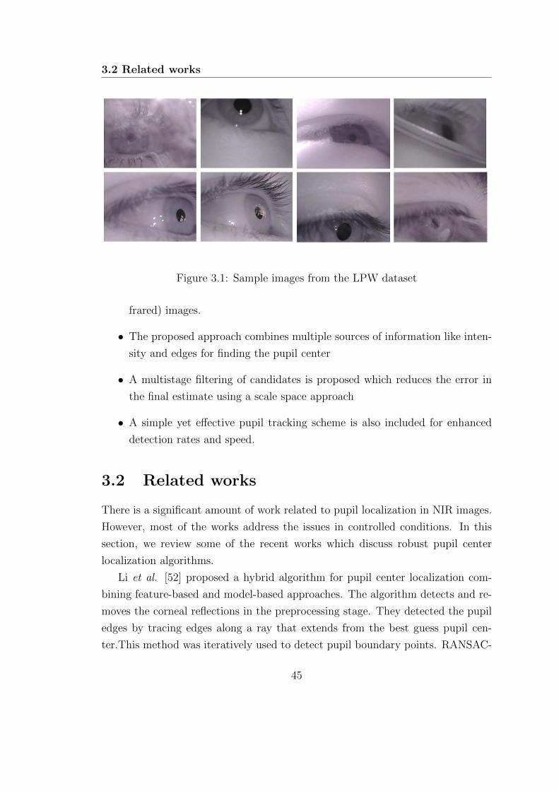
3.2 Related works
Figure 3.1: Sample images from the LPW dataset
frared) images.
• The proposed approach combines multiple sources of information like inten-
sity and edges for finding the pupil center
• A multistage filtering of candidates is proposed which reduces the error in
the final estimate using a scale space approach
• A simple yet effective pupil tracking scheme is also included for enhanced
detection rates and speed.
3.2 Related works
There is a significant amount of work related to pupil localization in NIR images.
However, most of the works address the issues in controlled conditions. In this
section, we review some of the recent works which discuss robust pupil center
localization algorithms.
Li et al. [52] proposed a hybrid algorithm for pupil center localization com-
bining feature-based and model-based approaches. The algorithm detects and re-
moves the corneal reflections in the preprocessing stage. They detected the pupil
edges by tracing edges along a ray that extends from the best guess pupil cen-
ter.This method was iteratively used to detect pupil boundary points. RANSAC-
45
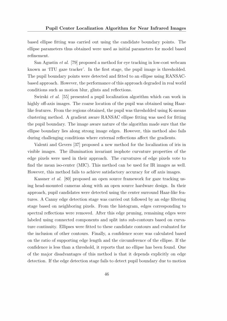
Pupil Center Localization Algorithm for Near Infrared Images
based ellipse fitting was carried out using the candidate boundary points. The
ellipse parameters thus obtained were used as initial parameters for model based
refinement.
San Agustin et al. [79] proposed a method for eye tracking in low-cost webcam
known as ‘ITU gaze tracker’. In the first stage, the pupil image is thresholded.
The pupil boundary points were detected and fitted to an ellipse using RANSAC-
based approach. However, the performance of this approach degraded in real world
conditions such as motion blur, glints and reflections.
Swirski et al. [55] presented a pupil localization algorithm which can work in
highly off-axis images. The coarse location of the pupil was obtained using Haar-
like features. From the regions obtained, the pupil was thresholded using K-means
clustering method. A gradient aware RANSAC ellipse fitting was used for fitting
the pupil boundary. The image aware nature of the algorithm made sure that the
ellipse boundary lies along strong image edges. However, this method also fails
during challenging conditions where external reflections affect the gradients.
Valenti and Gevers [37] proposed a new method for the localization of iris in
visible images. The illumination invariant isophote curvature properties of the
edge pixels were used in their approach. The curvatures of edge pixels vote to
find the mean iso-center (MIC). This method can be used for IR images as well.
However, this method fails to achieve satisfactory accuracy for off axis images.
Kassner et al. [80] proposed an open source framework for gaze tracking us-
ing head-mounted cameras along with an open source hardware design. In their
approach, pupil candidates were detected using the center surround Haar-like fea-
tures. A Canny edge detection stage was carried out followed by an edge filtering
stage based on neighboring pixels. From the histogram, edges corresponding to
spectral reflections were removed. After this edge pruning, remaining edges were
labeled using connected components and split into sub-contours based on curva-
ture continuity. Ellipses were fitted to these candidate contours and evaluated for
the inclusion of other contours. Finally, a confidence score was calculated based
on the ratio of supporting edge length and the circumference of the ellipse. If the
confidence is less than a threshold, it reports that no ellipse has been found. One
of the major disadvantages of this method is that it depends explicitly on edge
detection. If the edge detection stage fails to detect pupil boundary due to motion
46

3.2 Related works
blur or illumination, subsequent stages could fail.
Javadi et al. [81] proposed SET approach, in which a manual threshold was
used for thresholding the image. The connected components were treated as pupil
candidates, and their convex hull was found. An ellipse fitting stage was followed,
and the ellipse which was closest to the circle shape was selected as the final pupil
location.
Fuhl et al. [82] presented a robust algorithm for PC localization in off-axis
images. In the initial stage, the images were normalized, and the peak of the
histogram was found. If the peak was found, the pipeline using edge filtering
approach was used. The edges detected from Canny algorithm were filtered using
morphological operations for removing lines and orthogonal edges. Straight lines
were detected and removed using the distance of points to their centroids. The
curve with lowest enclosed intensity was selected and fitted with an ellipse. In
case peak was not found, the algorithm finds the coarse location of the pupil
and refines it based on angular projection functions. The thresholded image was
further refined and fitted with an ellipse. Fuhl et al. [83] further extended the
work in [82] improving it by the use of ellipse selection from Canny edges. After
detection of edges using the Canny filter, edge segments were evaluated similarly
as used in ExCuSe [82]. The segments were evaluated for various constraints
including straightness, the inner intensity value and the best one was fitted. In
case ellipse detection fails, likely locations of the pupil were found. The image
was downscaled and convolved with a surface difference filter and a mean filter.
The location of the maximum value in the multiplied result was used as the initial
point for position refinement. The position is refined based on the analysis of
surrounding pixels. The center of mass of the pixels with the new threshold is
used as the updated pupil position. This location is evaluated with a validity
check using the surface difference.
Most of the methods use multiple stages for PC localization. However, the
rather simple assumptions of the pupil as the darkest region produces a lot of false
detections. Head mounted trackers are supposed to work in real world applications,
and they should perform robustly in real world conditions. To this end, ElSe
approach proposed by Fuhl et al. [83] is robust. However, their method relies
heavily on the Canny edge detector. Once the detector fails to detect the edges
47
Pupil Center Localization Algorithm for Near Infrared Images
correctly due to glints or reflections, the second stage cannot recover if the edge
detection fails. Further, they do not leverage the temporal information.
Therefore, we propose a novel method which works even with challenging con-
ditions such as glints, extreme angles, partial occlusion, image blur and illumina-
tion variations. Further, we introduce a simple yet effective pupil tracking scheme
which makes the detection faster. Usage of the temporal information reduces the
search space for pupil localization while decreasing the false positives.
3.3 Proposed method
Two basic approaches are commonly used for localizing pupil center in dark pupil
images. The first method uses the intensity distribution of the images. The pupil
region is assumed as the darkest region in the image which can be well separated
from the background. Some of the approaches use a manual threshold which is
adjusted according to the imaging conditions. However, this method fails when
other regions appear dark due to the shadows. Further, it may not be possible
to find an exact threshold to segment out the pupil due to the varying external
lighting and the glints.
Another approach uses edges of the image which can be found using Canny
edge detector. The edges detected are filtered morphologically and using several
other constraints. Candidate edge segments identified, and ellipse fitting is carried
out. However, edge detection stage might fail due to external illumination, glints,
and motion blur. In such conditions, the Canny edge detector fails in detecting
the pupil boundaries resulting in the failure of subsequent stages.
In our approach, we used intensity distribution, edges, image gradients and
several other parameters to estimate the pupil center. The stages of the proposed
method and the overall framework is shown in Fig. 3.2.
3.3.1 Preprocessing and edge detection
The native resolution of the camera used is 640 × 480. The images captured are
downsampled by a factor of two to reduce the computational requirement. They
are converted to grayscale and are scaled to the range of 0-255.
48
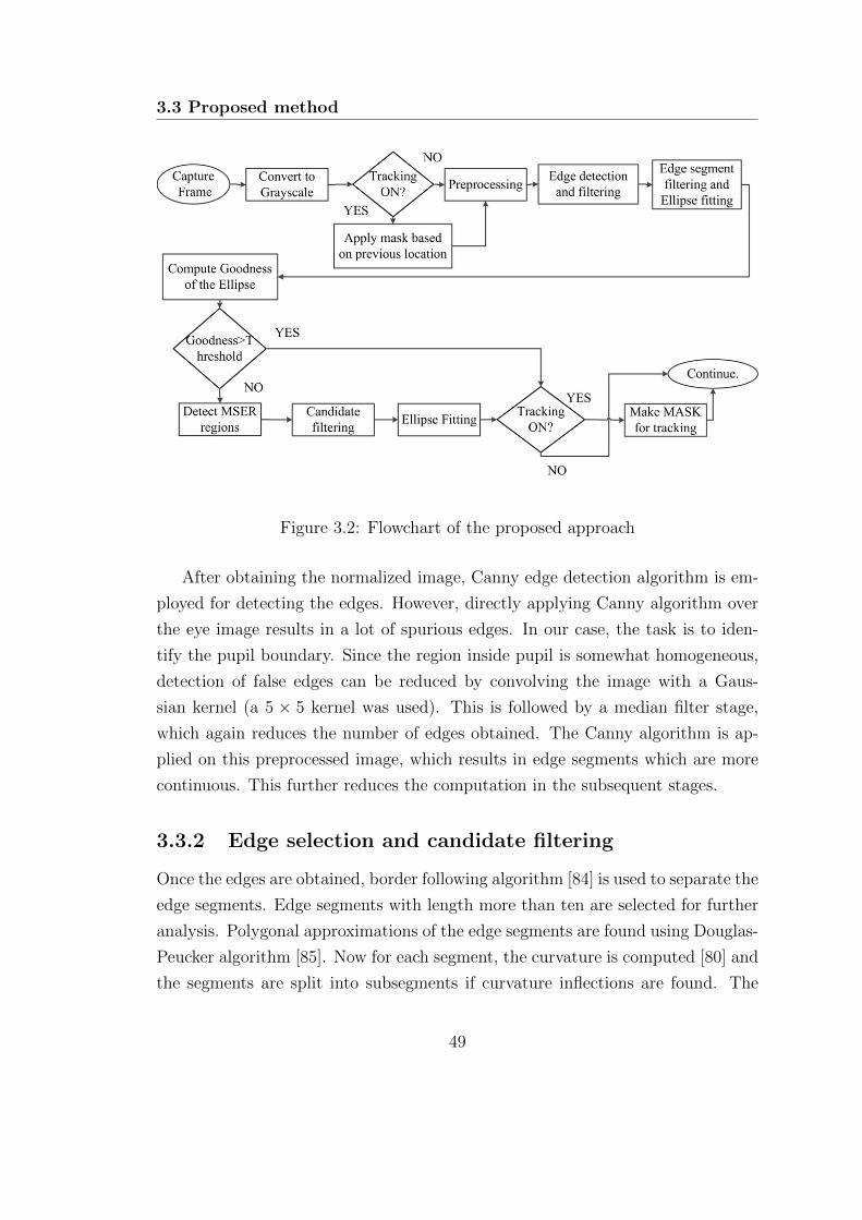
3.3 Proposed method
Figure 3.2: Flowchart of the proposed approach
After obtaining the normalized image, Canny edge detection algorithm is em-
ployed for detecting the edges. However, directly applying Canny algorithm over
the eye image results in a lot of spurious edges. In our case, the task is to iden-
tify the pupil boundary. Since the region inside pupil is somewhat homogeneous,
detection of false edges can be reduced by convolving the image with a Gaus-
sian kernel (a 5 × 5 kernel was used). This is followed by a median filter stage,
which again reduces the number of edges obtained. The Canny algorithm is ap-
plied on this preprocessed image, which results in edge segments which are more
continuous. This further reduces the computation in the subsequent stages.
3.3.2 Edge selection and candidate filtering
Once the edges are obtained, border following algorithm [84] is used to separate the
edge segments. Edge segments with length more than ten are selected for further
analysis. Polygonal approximations of the edge segments are found using Douglas-
Peucker algorithm [85]. Now for each segment, the curvature is computed [80] and
the segments are split into subsegments if curvature inflections are found. The
49
Pupil Center Localization Algorithm for Near Infrared Images
candidate edge segments are evaluated for the suitability of being a pupil boundary.
For this, we introduce new criteria based on ellipse fitting, each edge segment is
fitted with an ellipse using a least square approach [86]. Candidate edge segments
are pruned based on the area and the aspect ratio of the fitted ellipses. Edge
segments which are too small or too large are rejected at this stage. The median
intensity of the inner region of candidate edge segments are found, and candidates
with inner intensity less than an empirically determined threshold are selected for
further analysis. We use a new method for candidate edge filtering and merging.
The edge segments are sorted based on the median of the inner intensities. In
the next stage, the edge candidates belonging to the pupil boundary are merged.
A combinatorial search is carried out to determine the whether two candidates
belong to the same ellipse. Two parameters are considered in this search, i.e.
1) the similarity of median grayscale value enclosed by the segment, and 2) the
Euclidean distance between the centers of the fitted ellipses. Edge segments are
merged if these two criteria are satisfied. The combined boundary is fitted with an
ellipse, and a goodness parameter is computed. The median difference of grayscale
values from the inner and outer, along with the edge support is also computed.
We use the goodness of fit parameter proposed in chapter 2. The center of the
ellipse is returned as the pupil center if the goodness parameter is greater than an
empirically selected threshold.
Edge based ellipse fitting can fail when the edges in the image are weak. Motion
blur, low contrast, external lighting and noise can also result in the failure of the
edge detection stage. If the edge based fitting fails, we use grayscale intensity
distribution to identify the pupil center candidates.
3.3.3 Candidate detection with MSER
If the edge-based fitting fails, the algorithm tries to detect the pupil location
using the grayscale intensity as shown in Fig. 3.4. We apply a candidate filtering
approach for obtaining the pupil center. In the first stage, different candidate
regions are identified using a variant of maximally stable extremal regions (MSER)
proposed by Matas et al. [87]. In the second stage, the candidate regions are
evaluated for ellipse fitting criterion and the best candidate is selected as the
50
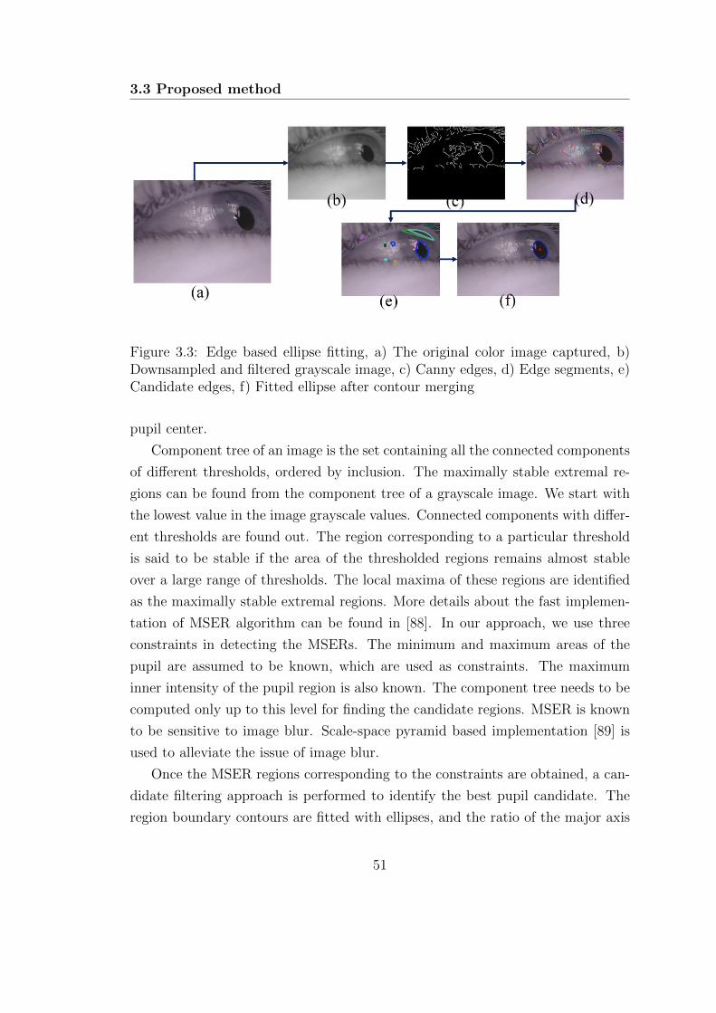
3.3 Proposed method
Figure 3.3: Edge based ellipse fitting, a) The original color image captured, b)Downsampled and filtered grayscale image, c) Canny edges, d) Edge segments, e)Candidate edges, f) Fitted ellipse after contour merging
pupil center.
Component tree of an image is the set containing all the connected components
of different thresholds, ordered by inclusion. The maximally stable extremal re-
gions can be found from the component tree of a grayscale image. We start with
the lowest value in the image grayscale values. Connected components with differ-
ent thresholds are found out. The region corresponding to a particular threshold
is said to be stable if the area of the thresholded regions remains almost stable
over a large range of thresholds. The local maxima of these regions are identified
as the maximally stable extremal regions. More details about the fast implemen-
tation of MSER algorithm can be found in [88]. In our approach, we use three
constraints in detecting the MSERs. The minimum and maximum areas of the
pupil are assumed to be known, which are used as constraints. The maximum
inner intensity of the pupil region is also known. The component tree needs to be
computed only up to this level for finding the candidate regions. MSER is known
to be sensitive to image blur. Scale-space pyramid based implementation [89] is
used to alleviate the issue of image blur.
Once the MSER regions corresponding to the constraints are obtained, a can-
didate filtering approach is performed to identify the best pupil candidate. The
region boundary contours are fitted with ellipses, and the ratio of the major axis
51
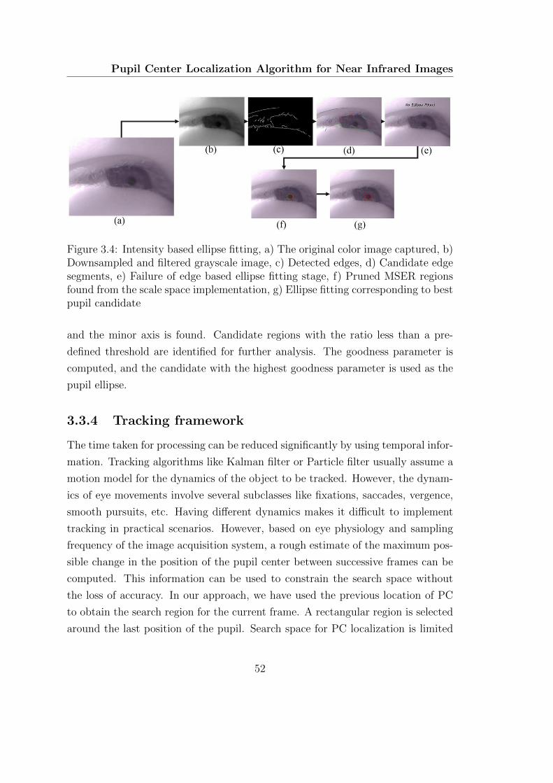
Pupil Center Localization Algorithm for Near Infrared Images
Figure 3.4: Intensity based ellipse fitting, a) The original color image captured, b)Downsampled and filtered grayscale image, c) Detected edges, d) Candidate edgesegments, e) Failure of edge based ellipse fitting stage, f) Pruned MSER regionsfound from the scale space implementation, g) Ellipse fitting corresponding to bestpupil candidate
and the minor axis is found. Candidate regions with the ratio less than a pre-
defined threshold are identified for further analysis. The goodness parameter is
computed, and the candidate with the highest goodness parameter is used as the
pupil ellipse.
3.3.4 Tracking framework
The time taken for processing can be reduced significantly by using temporal infor-
mation. Tracking algorithms like Kalman filter or Particle filter usually assume a
motion model for the dynamics of the object to be tracked. However, the dynam-
ics of eye movements involve several subclasses like fixations, saccades, vergence,
smooth pursuits, etc. Having different dynamics makes it difficult to implement
tracking in practical scenarios. However, based on eye physiology and sampling
frequency of the image acquisition system, a rough estimate of the maximum pos-
sible change in the position of the pupil center between successive frames can be
computed. This information can be used to constrain the search space without
the loss of accuracy. In our approach, we have used the previous location of PC
to obtain the search region for the current frame. A rectangular region is selected
around the last position of the pupil. Search space for PC localization is limited
52
3.4 Experiments
to this area only. However, selection of this mask depends on the confidence of
PC localization, the mask from the previous frame is used only when the goodness
parameter for ellipse fitting is more than an empirically found threshold. If the
ellipse fitting stage in the previous frame does not result in a high Goodness fac-
tor, the entire image is searched for localizing PC. This simple approach achieves
better frame rates while removing many false detections. The main advantage of
this method is that it gets rid of redundant computations and limits the processing
to more promising areas using the temporal information.
3.3.5 Comparison with state of the art method
The closest method related to the proposed approach is ElSe [83] proposed by
Fuhl et al., as they also use two different pipelines based on the imaging condi-
tions. In the first stage, they have used Canny edge detector followed by complex
algorithmic and morphological filtering, whereas in the proposed approach most
spurious edges are rejected by downsampling followed by Gaussian filtering. We
have introduced new criteria for edge filtering based on the geometric distance and
the inner intensity difference of the fitted ellipses. In the event of failure of the
edge based stage, the second stage is performed which uses scale space variant of
MSER algorithm followed by the proposed candidate filtering to identify the best
pupil candidate. Further, the proposed method introduces a tracking approach
which reduces the search space based on the confidence levels obtained from the
ellipse fitting stage.
3.4 Experiments
3.4.1 Labeled Pupils in the Wild database
We have used labeled pupils in the wild (LPW) database [90] for the algorithm
evaluation since the number of images is large and it contains images recorded in
real world conditions. LPW dataset contains 66 high-quality videos of eye regions
from 22 subjects, including samples from people of different ethnicities, indoor
and outdoor illumination variations in different gaze directions. It also contains
53
Pupil Center Localization Algorithm for Near Infrared Images
images of participants wearing glasses, contact lenses and makeup. Each video
in the database contains around 2000 images of resolution 640× 480 recorded at
a frame rate of 95 fps. The dataset contains a total of 130,856 images which is
much larger than any of the existing datasets. Ground truth pupil locations are
also available with the dataset.
3.4.2 Evaluation of the algorithm
We have evaluated the proposed algorithm in 66 videos provided in the dataset.
The pixel error in each frame was computed from the ground truth available with
the dataset. The comparison with state of the art is made based on the data as
in [91].
The result obtained from the proposed algorithm has been compared with six
other state of the art methods available in the literature. We have compared the
results with Starburst [52], Swirski [55], SET [81], Pupil Labs [80], ExCuSE [82],
and ElSE [83].
The results obtained, and the comparison with state of the art are shown in
Fig. 3.5. The proposed approach outperforms all the state of the art methods.
Comparative results for an error of five pixels is provided in Table. 3.1. The
proposed method obtains best overall accuracy.
The results obtained with and without tracking are shown in Fig. 3.6. The
addition of tracking decreased the processing load without any decrease in accu-
racy. The results obtained with tracking are slightly better than individual frame
based detections. This can be attributed to the reduction in false detections due
to the masking used in the tracking approach.
Some of the successful detections and failures are shown in Fig. 3.7. Fig. 3.8
shows some of the challenging images from the LPW dataset.
54
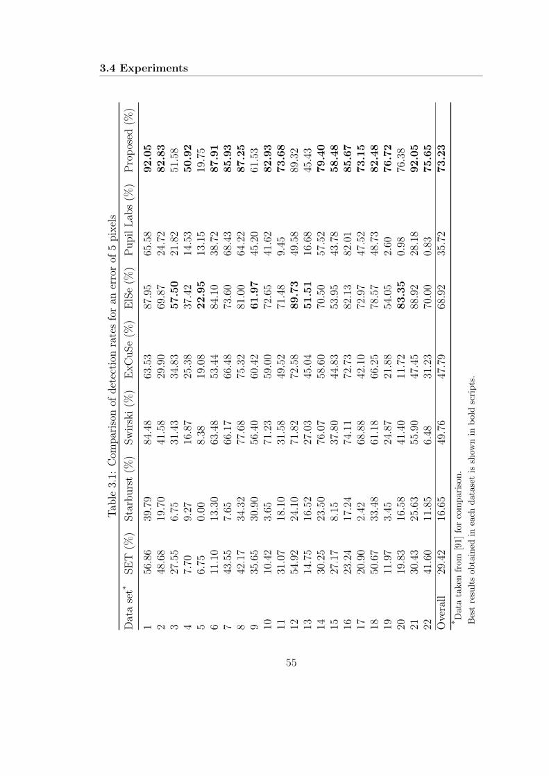
3.4 Experiments
Tab
le3.
1:C
ompar
ison
ofdet
ecti
onra
tes
for
aner
ror
of5
pix
els
Dat
ase
t*SE
T(%
)Sta
rburs
t(%
)Sw
irsk
i(%
)E
xC
uSe
(%)
ElS
e(%
)P
upil
Lab
s(%
)P
rop
osed
(%)
156
.86
39.7
984
.48
63.5
387
.95
65.5
892.0
52
48.6
819
.70
41.5
829
.90
69.8
724
.72
82.8
33
27.5
56.
7531
.43
34.8
357.5
021
.82
51.5
84
7.70
9.27
16.8
725
.38
37.4
214
.53
50.9
25
6.75
0.00
8.38
19.0
822.9
513
.15
19.7
56
11.1
013
.30
63.4
853
.44
84.1
038
.72
87.9
17
43.5
57.
6566
.17
66.4
873
.60
68.4
385.9
38
42.1
734
.32
77.6
875
.32
81.0
064
.22
87.2
59
35.6
530
.90
56.4
060
.42
61.9
745
.20
61.5
310
10.4
23.
6571
.23
59.0
072
.65
41.6
282.9
311
31.0
718
.10
31.5
849
.52
71.4
89.
4573.6
812
54.9
224
.10
71.8
272
.58
89.7
349
.58
89.3
213
14.7
516
.52
27.0
345
.04
51.5
116
.68
45.4
314
30.2
523
.50
76.0
758
.60
70.5
057
.52
79.4
015
27.1
78.
1537
.80
44.8
353
.95
43.7
858.4
816
23.2
417
.24
74.1
172
.73
82.1
382
.01
85.6
717
20.9
02.
4268
.88
42.1
072
.97
47.5
273.1
518
50.6
733
.48
61.1
866
.25
78.5
748
.73
82.4
819
11.9
73.
4524
.87
21.8
854
.05
2.60
76.7
220
19.8
316
.58
41.4
011
.72
83.3
50.
9876
.38
2130
.43
25.6
355
.90
47.4
588
.92
28.1
892.0
522
41.6
011
.85
6.48
31.2
370
.00
0.83
75.6
5O
vera
ll29
.42
16.6
549
.76
47.7
968
.92
35.7
273.2
3*D
ata
take
nfr
om[9
1]fo
rco
mp
aris
on.
Bes
tre
sult
sob
tain
edin
each
dat
aset
issh
own
inb
old
scri
pts
.
55
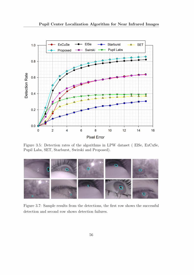
Pupil Center Localization Algorithm for Near Infrared Images
Figure 3.5: Detection rates of the algorithms in LPW dataset ( ElSe, ExCuSe,Pupil Labs, SET, Starburst, Swirski and Proposed).
Figure 3.7: Sample results from the detections, the first row shows the successful
detection and second row shows detection failures.
56
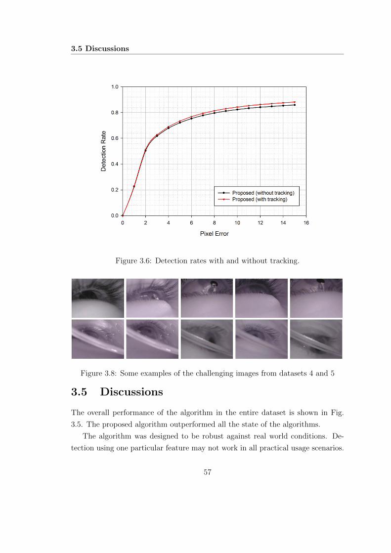
3.5 Discussions
Figure 3.6: Detection rates with and without tracking.
Figure 3.8: Some examples of the challenging images from datasets 4 and 5
3.5 Discussions
The overall performance of the algorithm in the entire dataset is shown in Fig.
3.5. The proposed algorithm outperformed all the state of the algorithms.
The algorithm was designed to be robust against real world conditions. De-
tection using one particular feature may not work in all practical usage scenarios.
57
Pupil Center Localization Algorithm for Near Infrared Images
The proposed algorithm switches to either edge based method or intensity based
method depending upon the image conditions. One significant advantage here
is that, even if the first edge based stage of the algorithm fails due to some re-
flections, the second stage can identify the pupil (though more computation is
required). Further, the tracking approach reduces false detection rate at the same
time reduces computational load as the search space is considerably less. Most
of the algorithms are designed to maximize the per frame based detection rates.
Here, we have added the tracking framework which directly extends the algorithm
for video. Results with and without tracking are shown in Fig. 3.6. The tracking
scheme achieved slightly better results with a better runtime performance.
3.5.1 Execution time
The algorithms were implemented on a desktop computer with 64 bit Ubuntu
13.10 Operating system having 3.33 GHz core i5 processor, and 8GB RAM. Im-
plementation with unoptimized python code obtained an average processing time
of 14.28 ms/frame without tracking and 9.90 ms/frame with tracking. There is a
scope for improving the processing time by code optimization.
3.5.2 Limitations
The algorithm detects the pupil centers accurately when the edges are correctly
detected. Intensity based candidate filtering approach detects the pupil when the
edge-based approach fails. However, the algorithm fails when the pupil is occluded
as shown Fig. 3.8 (dataset 5). The edges are not properly detected because of
blur. Intensity based approach could also fail since the candidates are occluded.
This reduces the goodness of regions obtained. Another failure case can occur
when the image contrast is poor, and the surrounding regions have low contrast
and reflections. A machine learning based approach can be used to compensate
for the detection-failures in such challenging cases.
58

3.6 Summary
3.6 Summary
In this chapter, we have presented a framework for pupil center localization in
dark pupil images. The algorithm works in images captured with a head-mounted
eye tracker using dark pupil method. The primary objective of the work was to
develop an accurate algorithm which would work in real world conditions. The
algorithm takes care of both intensity and edge information to estimate the pupil
center accurately. A candidate filtering approach is chosen which maximizes a
goodness function returning the best possible pupil candidate. A simple tracking
method has also been used. It reduces the computations required without com-
promising on the accuracy. The proposed approach has been evaluated on LPW
dataset and found to outperform all the state of the art methods. The python-
based implementation achieves frame rates close to 100, which can be improved
with an optimized implementation in C/C++. The high frame rates obtained
can be useful in adding additional post processing and more computationally so-
phisticated tracking algorithms for improving the accuracy even further. Online
identification of the eye movement types can be helpful in using appropriate model
for tracking eye movements during different movement types.
59

C H A P T E R 4
Eye Gaze Direction Classification
Using Convolutional Neural
Network
This chapter presents a real-time framework for the classification of eye gaze
direction. A convolutional neural network is employed in this work for the
classification of eye gaze direction. The proposed gaze direction obtained can
be readily used for various HCI applications since it does not require a person
dependant calibration stage.
4.1 Introduction
Human eyes provide rich information about human cognitive processes and emo-
tions. The gaze patterns of eyes also contains information about fatigue [92],
diseases [93], etc. Estimation of gaze direction can be useful in various domains,
including psychology, disease diagnosis, and human computer interaction. Gaze di-
rection changes can be used as an interaction channel virtual environments. They
61

Gaze Direction Classification Using Convolutional Neural Network
can also be used in applications like gaze based gestures, eye contact identification,
eye based typing, etc.
Most of the existing eye trackers require a cumbersome calibration procedure.
A person independent gaze classification system can be useful in scenarios where
obtaining calibration data is difficult, such, gaze tracking in public displays and
experiments with children.
In this chapter, we present a real-time framework which can detect eye gaze
direction using off-the-shelf, low-cost cameras in desktops and other smart devices.
We treat the gaze direction classification as a multi-class classification problem,
avoiding the need for calibration.
Figure 4.1: Different EACs in NLP theory
4.1.1 Application in finding Eye Accessing Cues
The patterns in which the eyes move when humans access their memories is known
as eye accessing cues (EAC). The neuro-linguistic programming (NLP) EAC the-
ory suggests [94] that there is a correlation between eye-movements and cognitive
processing while accessing experiences. EAC theory suggests that the meaning
of non-visual gaze directions may be directly related to the internal mental pro-
cesses. These movements are reported to be related to the neural pathways which
deal with memory and sensory information. The direction of the iris in the socket
can give information regarding various cognitive processes. Each direction of non-
62
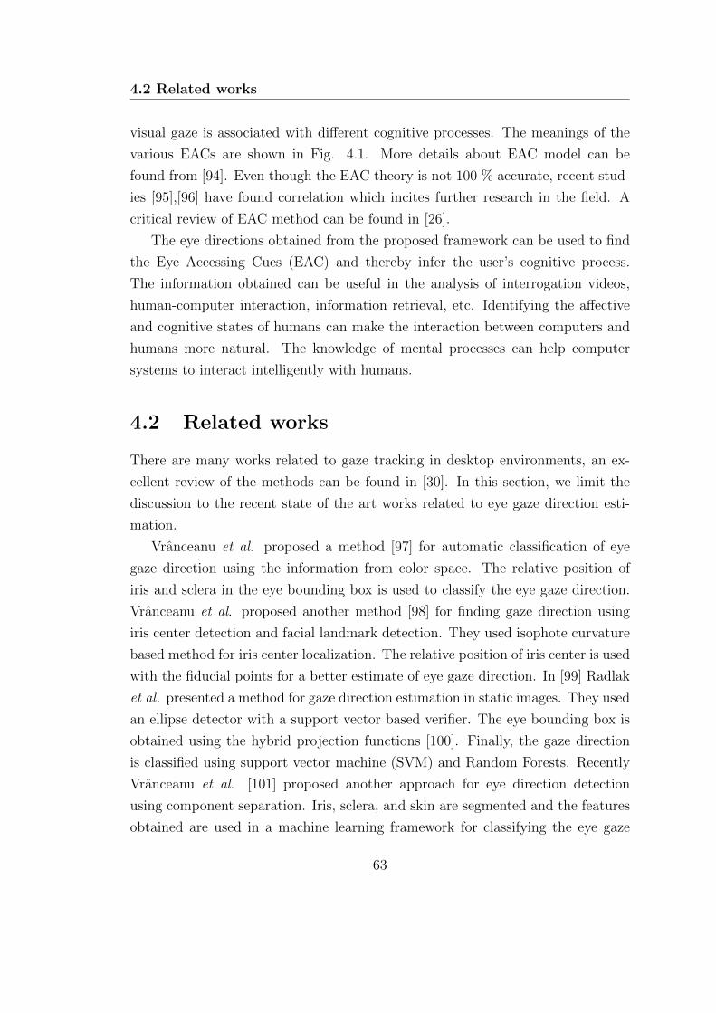
4.2 Related works
visual gaze is associated with different cognitive processes. The meanings of the
various EACs are shown in Fig. 4.1. More details about EAC model can be
found from [94]. Even though the EAC theory is not 100 % accurate, recent stud-
ies [95],[96] have found correlation which incites further research in the field. A
critical review of EAC method can be found in [26].
The eye directions obtained from the proposed framework can be used to find
the Eye Accessing Cues (EAC) and thereby infer the user’s cognitive process.
The information obtained can be useful in the analysis of interrogation videos,
human-computer interaction, information retrieval, etc. Identifying the affective
and cognitive states of humans can make the interaction between computers and
humans more natural. The knowledge of mental processes can help computer
systems to interact intelligently with humans.
4.2 Related works
There are many works related to gaze tracking in desktop environments, an ex-
cellent review of the methods can be found in [30]. In this section, we limit the
discussion to the recent state of the art works related to eye gaze direction esti-
mation.
Vranceanu et al. proposed a method [97] for automatic classification of eye
gaze direction using the information from color space. The relative position of
iris and sclera in the eye bounding box is used to classify the eye gaze direction.
Vranceanu et al. proposed another method [98] for finding gaze direction using
iris center detection and facial landmark detection. They used isophote curvature
based method for iris center localization. The relative position of iris center is used
with the fiducial points for a better estimate of eye gaze direction. In [99] Radlak
et al. presented a method for gaze direction estimation in static images. They used
an ellipse detector with a support vector based verifier. The eye bounding box is
obtained using the hybrid projection functions [100]. Finally, the gaze direction
is classified using support vector machine (SVM) and Random Forests. Recently
Vranceanu et al. [101] proposed another approach for eye direction detection
using component separation. Iris, sclera, and skin are segmented and the features
obtained are used in a machine learning framework for classifying the eye gaze
63
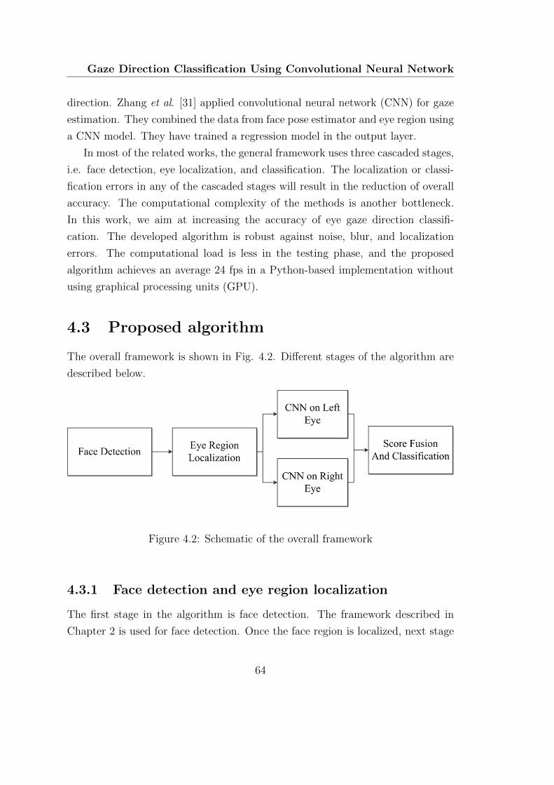
Gaze Direction Classification Using Convolutional Neural Network
direction. Zhang et al. [31] applied convolutional neural network (CNN) for gaze
estimation. They combined the data from face pose estimator and eye region using
a CNN model. They have trained a regression model in the output layer.
In most of the related works, the general framework uses three cascaded stages,
i.e. face detection, eye localization, and classification. The localization or classi-
fication errors in any of the cascaded stages will result in the reduction of overall
accuracy. The computational complexity of the methods is another bottleneck.
In this work, we aim at increasing the accuracy of eye gaze direction classifi-
cation. The developed algorithm is robust against noise, blur, and localization
errors. The computational load is less in the testing phase, and the proposed
algorithm achieves an average 24 fps in a Python-based implementation without
using graphical processing units (GPU).
4.3 Proposed algorithm
The overall framework is shown in Fig. 4.2. Different stages of the algorithm are
described below.
Figure 4.2: Schematic of the overall framework
4.3.1 Face detection and eye region localization
The first stage in the algorithm is face detection. The framework described in
Chapter 2 is used for face detection. Once the face region is localized, next stage
64
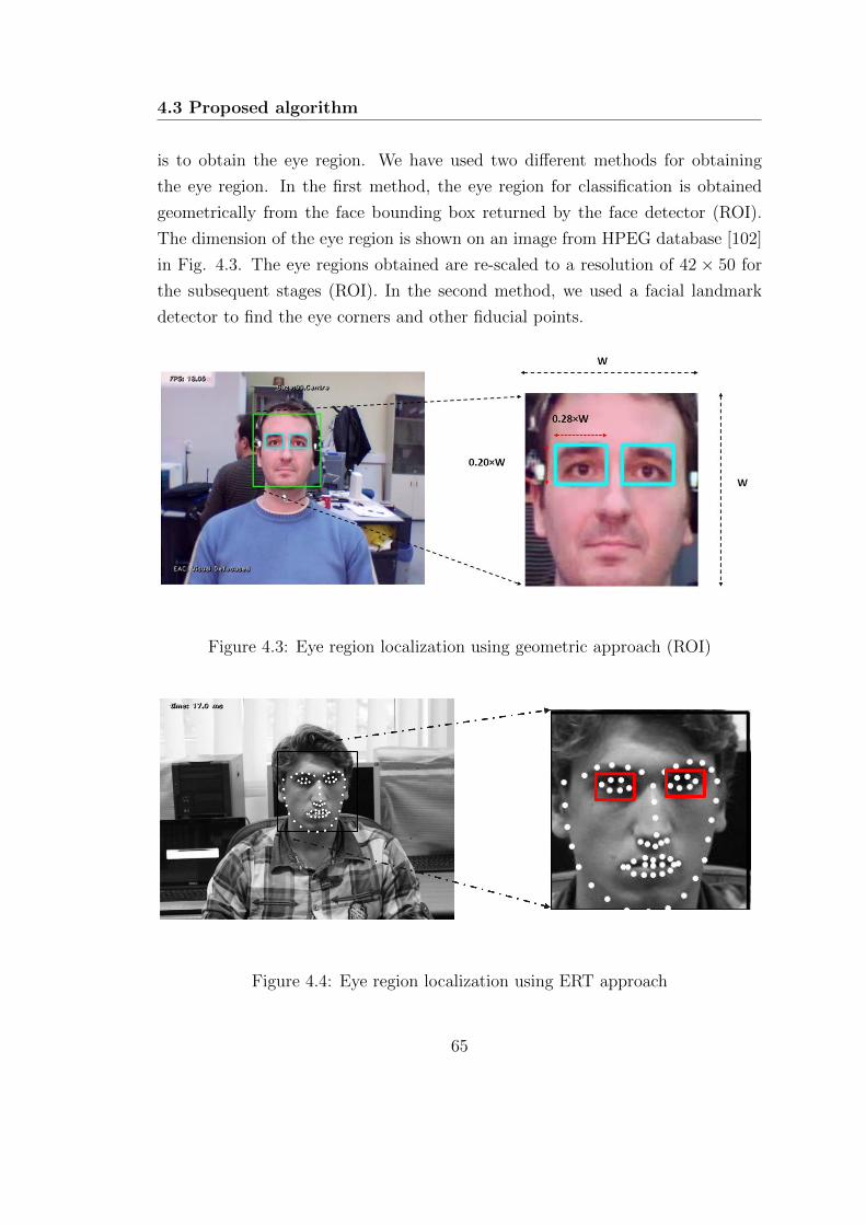
4.3 Proposed algorithm
is to obtain the eye region. We have used two different methods for obtaining
the eye region. In the first method, the eye region for classification is obtained
geometrically from the face bounding box returned by the face detector (ROI).
The dimension of the eye region is shown on an image from HPEG database [102]
in Fig. 4.3. The eye regions obtained are re-scaled to a resolution of 42 × 50 for
the subsequent stages (ROI). In the second method, we used a facial landmark
detector to find the eye corners and other fiducial points.
Figure 4.3: Eye region localization using geometric approach (ROI)
Figure 4.4: Eye region localization using ERT approach
65
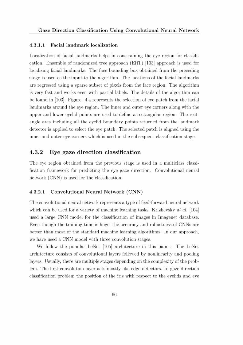
Gaze Direction Classification Using Convolutional Neural Network
4.3.1.1 Facial landmark localization
Localization of facial landmarks helps in constraining the eye region for classifi-
cation. Ensemble of randomized tree approach (ERT) [103] approach is used for
localizing facial landmarks. The face bounding box obtained from the preceding
stage is used as the input to the algorithm. The locations of the facial landmarks
are regressed using a sparse subset of pixels from the face region. The algorithm
is very fast and works even with partial labels. The details of the algorithm can
be found in [103]. Figure. 4.4 represents the selection of eye patch from the facial
landmarks around the eye region. The inner and outer eye corners along with the
upper and lower eyelid points are used to define a rectangular region. The rect-
angle area including all the eyelid boundary points returned from the landmark
detector is applied to select the eye patch. The selected patch is aligned using the
inner and outer eye corners which is used in the subsequent classification stage.
4.3.2 Eye gaze direction classification
The eye region obtained from the previous stage is used in a multiclass classi-
fication framework for predicting the eye gaze direction. Convolutional neural
network (CNN) is used for the classification.
4.3.2.1 Convolutional Neural Network (CNN)
The convolutional neural network represents a type of feed-forward neural network
which can be used for a variety of machine learning tasks. Krizhevsky at al. [104]
used a large CNN model for the classification of images in Imagenet database.
Even though the training time is huge, the accuracy and robustness of CNNs are
better than most of the standard machine learning algorithms. In our approach,
we have used a CNN model with three convolution stages.
We follow the popular LeNet [105] architecture in this paper. The LeNet
architecture consists of convolutional layers followed by nonlinearity and pooling
layers. Usually, there are multiple stages depending on the complexity of the prob-
lem. The first convolution layer acts mostly like edge detectors. In gaze direction
classification problem the position of the iris with respect to the eyelids and eye
66
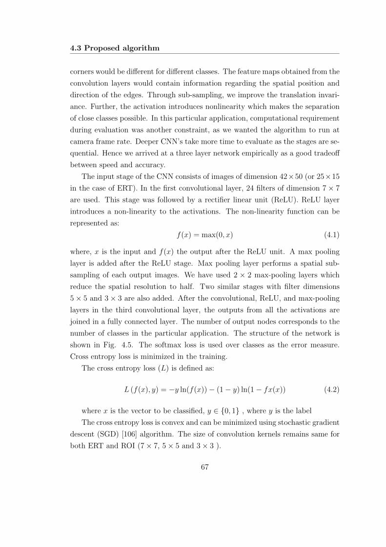
4.3 Proposed algorithm
corners would be different for different classes. The feature maps obtained from the
convolution layers would contain information regarding the spatial position and
direction of the edges. Through sub-sampling, we improve the translation invari-
ance. Further, the activation introduces nonlinearity which makes the separation
of close classes possible. In this particular application, computational requirement
during evaluation was another constraint, as we wanted the algorithm to run at
camera frame rate. Deeper CNN’s take more time to evaluate as the stages are se-
quential. Hence we arrived at a three layer network empirically as a good tradeoff
between speed and accuracy.
The input stage of the CNN consists of images of dimension 42×50 (or 25×15
in the case of ERT). In the first convolutional layer, 24 filters of dimension 7× 7
are used. This stage was followed by a rectifier linear unit (ReLU). ReLU layer
introduces a non-linearity to the activations. The non-linearity function can be
represented as:
f(x) = max(0, x) (4.1)
where, x is the input and f(x) the output after the ReLU unit. A max pooling
layer is added after the ReLU stage. Max pooling layer performs a spatial sub-
sampling of each output images. We have used 2 × 2 max-pooling layers which
reduce the spatial resolution to half. Two similar stages with filter dimensions
5× 5 and 3× 3 are also added. After the convolutional, ReLU, and max-pooling
layers in the third convolutional layer, the outputs from all the activations are
joined in a fully connected layer. The number of output nodes corresponds to the
number of classes in the particular application. The structure of the network is
shown in Fig. 4.5. The softmax loss is used over classes as the error measure.
Cross entropy loss is minimized in the training.
The cross entropy loss (L) is defined as:
L (f(x), y) = −y ln(f(x))− (1− y) ln(1− fx(x)) (4.2)
where x is the vector to be classified, y ∈ {0, 1} , where y is the label
The cross entropy loss is convex and can be minimized using stochastic gradient
descent (SGD) [106] algorithm. The size of convolution kernels remains same for
both ERT and ROI (7× 7, 5× 5 and 3× 3 ).
67
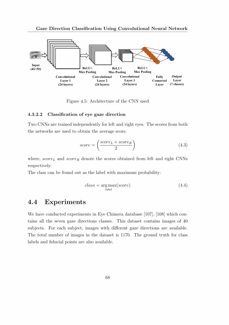
Gaze Direction Classification Using Convolutional Neural Network
Figure 4.5: Architecture of the CNN used
4.3.2.2 Classification of eye gaze direction
Two CNNs are trained independently for left and right eyes. The scores from both
the networks are used to obtain the average score.
score =
(scoreL + scoreR
2
)(4.3)
where, scoreL and scoreR denote the scores obtained from left and right CNNs
respectively.
The class can be found out as the label with maximum probability:
class = arg maxlabel
(score) (4.4)
4.4 Experiments
We have conducted experiments in Eye Chimera database [107], [108] which con-
tains all the seven gaze directions classes. This dataset contains images of 40
subjects. For each subject, images with different gaze directions are available.
The total number of images in the dataset is 1170. The ground truth for class
labels and fiducial points are also available.
68
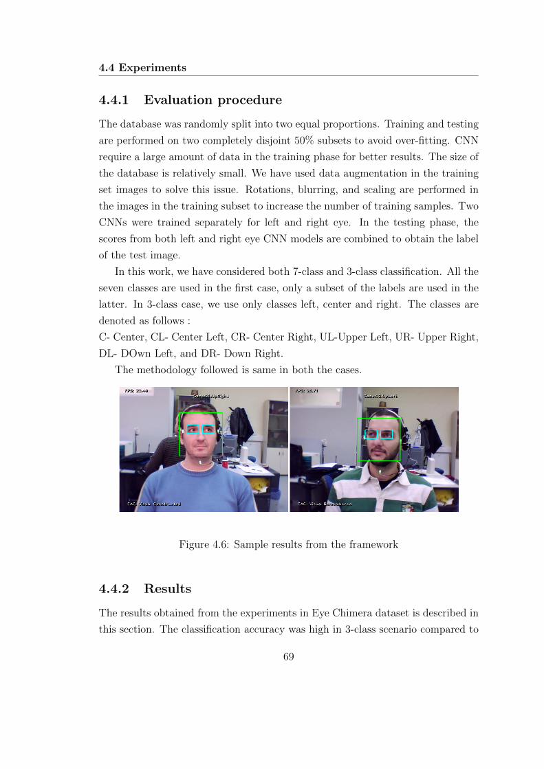
4.4 Experiments
4.4.1 Evaluation procedure
The database was randomly split into two equal proportions. Training and testing
are performed on two completely disjoint 50% subsets to avoid over-fitting. CNN
require a large amount of data in the training phase for better results. The size of
the database is relatively small. We have used data augmentation in the training
set images to solve this issue. Rotations, blurring, and scaling are performed in
the images in the training subset to increase the number of training samples. Two
CNNs were trained separately for left and right eye. In the testing phase, the
scores from both left and right eye CNN models are combined to obtain the label
of the test image.
In this work, we have considered both 7-class and 3-class classification. All the
seven classes are used in the first case, only a subset of the labels are used in the
latter. In 3-class case, we use only classes left, center and right. The classes are
denoted as follows :
C- Center, CL- Center Left, CR- Center Right, UL-Upper Left, UR- Upper Right,
DL- DOwn Left, and DR- Down Right.
The methodology followed is same in both the cases.
Figure 4.6: Sample results from the framework
4.4.2 Results
The results obtained from the experiments in Eye Chimera dataset is described in
this section. The classification accuracy was high in 3-class scenario compared to
69

Gaze Direction Classification Using Convolutional Neural Network
7-class case.
We have conducted experiments with the two different methods proposed. In
the first case, the eye region localization is carried out using geometrical relations.
Explicit landmark detection is avoided in this case. This approach is denoted
as ROI. This method reduces one stage in the overall framework. In the second
algorithm, we use the ERT based landmark detection scheme. The eye corners
obtained are used to constrain the region for subsequent classification stage. The
eye region obtained in each image is resized to a resolution of 20× 15 for further
processing.
In both the cases (ROI and ERT), the data was divided into two 50% subsets.
CNNs were trained separately for left and right eyes using data augmentation.
Testing was carried out with 50% disjoint testing set to avoid over-fitting effects.
All the experiments were repeated in both 3 class and 7 class scenario.
The results obtained by using only one eye are shown in Table 4.1.
Combining the information from both eyes improves the accuracy. The results
obtained using both the eyes and the comparison with state of the art is shown in
Table 4.3.
In both the cases, the proposed method outperforms all the state of the art
algorithms in eye gaze direction classification. Highest accuracy is obtained with
ERT+CNN algorithm. The individual accuracies achieved in the 7 class case is
shown in Table 4.2.
The confusion matrix for 3 class and 7 class case (ERT+CNN) are shown in
Fig. 4.7 and Fig. 4.8.
70
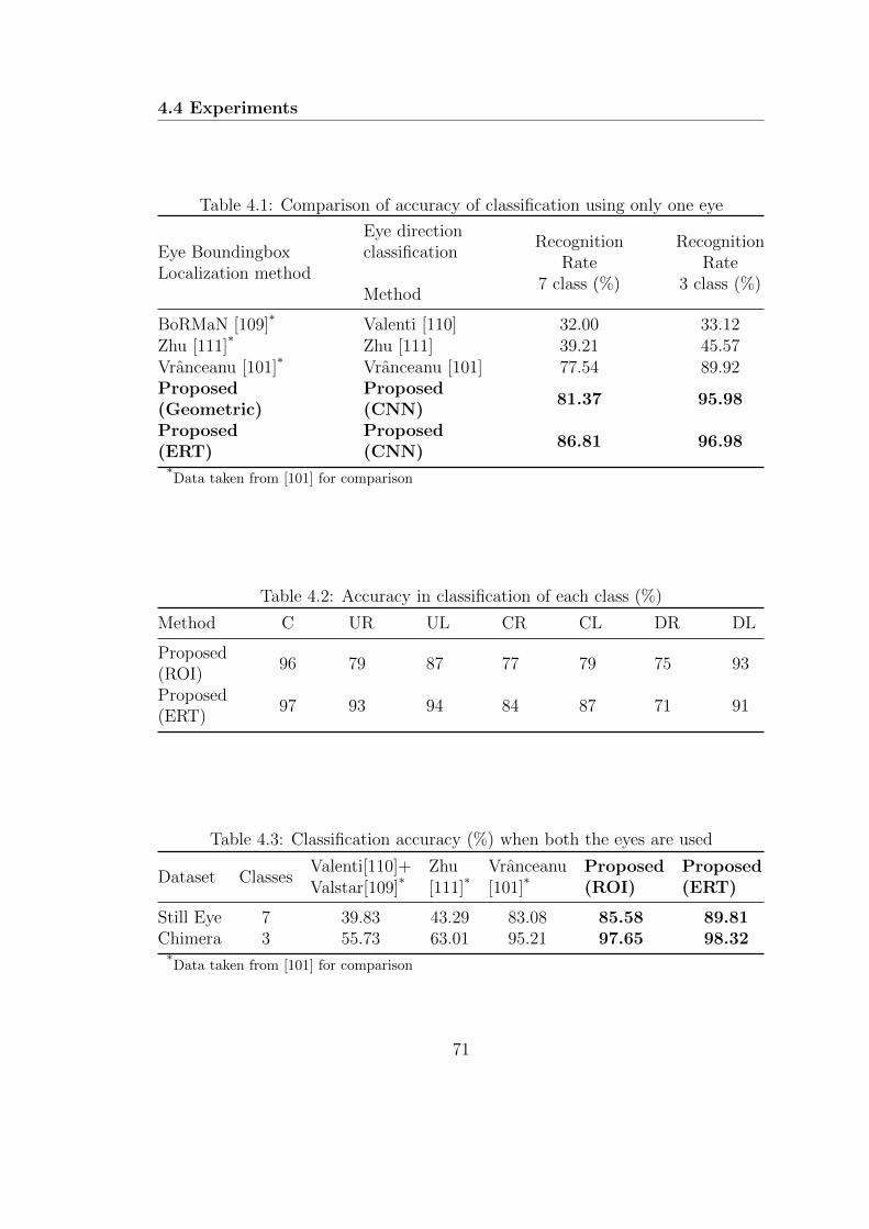
4.4 Experiments
Table 4.1: Comparison of accuracy of classification using only one eye
Eye BoundingboxLocalization method
Eye directionclassification
Method
RecognitionRate
7 class (%)
RecognitionRate
3 class (%)
BoRMaN [109]* Valenti [110] 32.00 33.12Zhu [111]* Zhu [111] 39.21 45.57Vranceanu [101]* Vranceanu [101] 77.54 89.92Proposed(Geometric)
Proposed(CNN)
81.37 95.98
Proposed(ERT)
Proposed(CNN)
86.81 96.98
*Data taken from [101] for comparison
Table 4.2: Accuracy in classification of each class (%)
Method C UR UL CR CL DR DL
Proposed(ROI)
96 79 87 77 79 75 93
Proposed(ERT)
97 93 94 84 87 71 91
Table 4.3: Classification accuracy (%) when both the eyes are used
Dataset ClassesValenti[110]+Valstar[109]*
Zhu[111]*
Vranceanu[101]*
Proposed(ROI)
Proposed(ERT)
Still EyeChimera
7 39.83 43.29 83.08 85.58 89.813 55.73 63.01 95.21 97.65 98.32
*Data taken from [101] for comparison
71
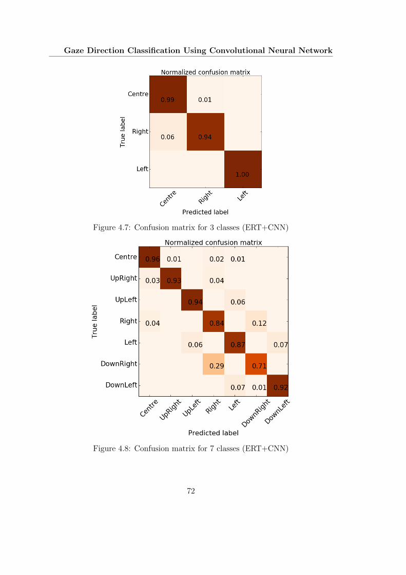
Gaze Direction Classification Using Convolutional Neural Network
Figure 4.7: Confusion matrix for 3 classes (ERT+CNN)
Figure 4.8: Confusion matrix for 7 classes (ERT+CNN)
72
4.5 Summary
4.4.3 Discussion
The proposed algorithm outperforms all the state of the art results reported in
the literature. The proposed algorithm leverages the information obtained from
the facial landmark detection stage to limit the computation to eye regions. The
alignment using eye corners reduces the intra-class variability. Score level fusion
from the two separately trained CNN’s further improve the accuracy.
From the confusion matrix, it can be seen that most of the miss-classifications
occur in differentiating between right and down right. The classification accuracy
is poor in the vertical direction (similar to the observations in [101]). This can be
attributed to the lack of spatial resolution in the vertical direction. Most of the
cases iris is partly occluded by eyelids in extreme corners. This makes it difficult
to classify them accurately. With the larger amount of labeled data, the algorithm
could perform even better.
4.5 Summary
In this chapter, a framework for real-time classification of eye gaze direction is
presented. The estimated eye gaze direction can also be used to infer eye accessing
cues, giving information about the cognitive states. The computational load is
very less; we achieved frame rates upto 24 Hz in Python implementation in a 2.0
GHz Core i5 desktop computer running Ubuntu 64 bit OS with 4GB RAM. The
per-frame computational time is 42 ms, which is much less than that of the other
state of the art methods (250 ms in [101]). Off the shelf webcams can be used
for computing the eye gaze direction. The eye gaze direction obtained can be
used for HCI applications. The computational requirements of the algorithm in
testing phase is less, which makes it suitable for smart devices with low-resolution
cameras using pre-trained models. A temporal filtering of the predicted scores
can be used in the case of video data. Using the color information in the CNN is
another path to be explored.
73

C H A P T E R 5
Eye Movement based Biometric
Authentication
This section presents a novel framework for biometric identification based on
eye movements. A large set of features is extracted from fixations and sac-
cades to characterize each individual. A backward selection approach is used
to identify important features. Two different Gaussian RBF networks are
trained using features from fixations and saccades separately. Score level fu-
sion approach is adopted for biometric authentication. The developed frame-
work was evaluated in BioEye 2015 dataset and was found to outperform state
of the art methods.
5.1 Introduction
Biometrics is an active area of research in pattern recognition and machine learn-
ing community. Potential applications of biometrics include forensics, law enforce-
ment, surveillance, personalized interaction, access control [112], etc. Physiological
features like fingerprint, DNA, earlobe geometry, iris pattern, facial recognition,
[113] are widely used in biometrics. Recently, several behavioral biometric modal-
75
Eye Movement based Biometric Authentication
ities have been proposed including gait, eye movement patterns, keystroke dy-
namics [114] signature, etc. Even though many such parameters like brain signals
[115] (using electroencephalogram) and heart beats [116] have been proposed as
biometric modalities, their invasive nature limits their practical applications.
An effective biometric should have the following characteristics [112]: (1) the
features should be unique for each individual, (2) they should not change with time
(template aging effects), (3) acquisition of parameters should be easy (low com-
putational complexity and noninvasive), (4) accurate and automated algorithms
should be available for classification, (5) counterfeit resistance, (6) low cost, and (7)
ease of implementation. Other characteristics that might make the system more
robust are portability and the ability to extract features from non-co-operative
subjects.
Out of many biometric modalities, iris recognition has shown the most promis-
ing results [117] obtaining equal error rates (EER) close to 0.0011%. However, it
can only be used when the user is co-operative. Such systems can be spoofed by
contact lenses with printed patterns. Even though most of the biometric modali-
ties perform well on evaluation databases, one may be able to spoof such systems
with mechanical replicas or artificially fabricated models [118]. In this regard,
several approaches have been presented [119] to detect the liveliness of tissues or
body parts presented to the biometric system. However, such methods are also
vulnerable to spoofing.
Biometrics using patterns obtained from eye movements is a relatively new field
of research. Most of the conventional biometrics use physiological characteristics of
the human body. Eye movement-based biometrics tries to identify the behavioral
patterns as well as information regarding physiological properties of tissues and
muscles generating eye movements [120]. They provide abundant information
about cognitive brain functions and neural signals controlling eye movements.
Eye movements as observed from outside is generated from an oculomotor
plant which consists of six extra-ocular muscles. Four of them are responsible for
horizontal and vertical movements namely the lateral and medial recti (horizon-
tal) and the superior and inferior recti (vertical). The torsional and coordinate
rotations of the eye are controlled by the other two muscles, the superior and the
inferior oblique. These muscles are controlled by axons of oculomotor, trochlear
76

5.2 Related works
and abducent nerves. There are complex mechanisms which control eye move-
ments, both physiological (structure of oculomotor system) and behavioral (the
neural circuitry guiding visual attention). The dynamics of the eye movement can
be modeled as an input output system where the neuron input to the muscles as
inputs and the eye movement as the output. The dynamics of the movement is
affected by the parameters of the system. Here the physiological properties of the
tissues and muscles including their elasticity, rotational inertia are manifested as
the parameters of the model. Manifestations of the unique combination of these
parameters could be used as a biometric trait.
Saccadic eye movement is the fastest movement (peak angular velocities up
to 900 degrees per second) in the human body. Mechanically replicating such a
complex oculomotor plant model is extremely difficult. These properties make eye
movement patterns a suitable candidate for biometric applications. The dynamics
of eye movement along with these properties can give inbuilt liveliness detection
capability.
Initially, eye movement biometrics has been proposed as a soft biometric. How-
ever, with the high level of accuracy achieved, it seems there are more opportunities
regarding its application as an independent biometric modality. Eye movement
detection can be integrated easily into already existing iris recognition systems.
A combination of iris recognition and eye movement pattern recognition may lead
to a robust counterfeit-resistant biometric modality with embedded liveliness de-
tection and continuous authentication properties. Eye movement biometrics can
also be made task-independent [121] so that the movements can be captured even
for non-co-operative subjects.
5.2 Related works
Initial attempts to use eye movements as a biometric modality were carried out by
Kasprowski and Ober [16]. They recorded the eye movements of subjects follow-
ing a jumping dot on a screen. Several frequency domain and Cepstral features
were extracted from this data. They applied different classification methods like
naive Bayes, C45 decision trees, SVM and KNN methods. The results obtained
further motivated research in eye movement-based biometrics. Bednarik et al.
77
Eye Movement based Biometric Authentication
[122] conducted experiments on several tasks including text reading, moving cross
stimulus tracking and free viewing of images. They used FFT and PCA on the eye
movement data. Several combinations of such features were tried. However, the
best results were obtained using the distance between eyes, which is not related to
eye dynamics. Komogortsev et al. [123] used an Oculomotor Plant Mathematical
Model (OPMM) to model the complex dynamics of the oculomotor plant. The
plant parameters were identified from the eye movement data. This approach was
further extended in [124]. Holland and Komogortsev [125] evaluated the applica-
bility of eye movement biometrics with different spatial and temporal accuracies
and various types of stimuli. Several parameters of eye movements were extracted
from fixations and saccades. Weighted components were used to compare different
samples for biometric identification. A temporal resolution of 250 Hz and spatial
accuracy of 0.5 degrees were identified as the minimum requirements for accurate
gaze-based biometric systems. Kinnunen et al. [121] presented a task-independent
user authentication system based on eye movements. Gaussian mixture modeling
of short-term gaze data was used in their approach. Even though the accuracy
rates were fairly low, the study opened up possibilities for the development of
task-independent eye movement-based verification systems. Rigas et al. [126] ex-
plored variations in individual gaze patterns while observing human face images.
Eye movements resulted were analyzed using a graph-based approach. The Mul-
tivariate Wald–Wolfowitz runs test was used to classify the eye movement data.
This method achieved 70% rank-1 IR and 30% EER on a database of 15 subjects.
Rigas et al. [127] extended this method using features of velocity and acceler-
ation calculated from fixations. The feature distributions were compared using
Wald–Wolfowitz test.
Zhang et al. [128] used saccadic eye movements with machine learning al-
gorithms for biometric verification. They used multilayer perceptron networks,
support vector machines, radial basis function networks and logistic discriminant
for the classification of eye movement data. Recently Cantoni et al. [129] proposed
a gaze analysis technique called GANT in which fixation patterns were denoted
by a graph-based representation. For each user, a fixation model was constructed
using the duration and number of visits at various points. Frobenius norm of the
density maps was used to find the similarity between two recordings. Holland
78
5.3 Proposed method
and Komogortsev presented an approach (CEM) [130] using several scan path
features including saccade amplitudes, average saccade velocities, average saccade
peak velocities, velocity waveform, fixation counts, average duration of fixation,
length of scan path, area of scan path, regions of interest, number of inflections,
main sequence relationship, pairwise distances between fixations, amplitude du-
ration relationship, etc. A comparison metric of the features was computed using
Gaussian cumulative density function. Another similarity metric was obtained by
comparing the scan paths. A weighted fusion of these parameters obtained the best
case EER of 27%. Holland and Komogortsev proposed a method (CEM-B)[131],
in which the fixation and saccade features were compared using statistical meth-
ods like Ansari–Bradley test, two-sample t-test, two-sample Kolmogorov–Smirnov
test, and the two-sample Cramer–von Mises test. Their approach achieved 83%
rank-1 IR and 16.5% EER on a dataset of 32 subjects.
To the best knowledge of the authors, the best case EER obtained is 16.5%
[131]. Most of the works presented in the literature were evaluated on smaller
databases. The effect of template aging was not considered in these works. For
the application of eye movement as a reliable biometric, the patterns should remain
consistent with time. In this work, we try to improve upon the existing methods.
The proposed algorithm can reach an EER up to 2.59% and rank-1 accuracy
of 89.54% in RAN 30min dataset of BioEye 2015 database [132] containing 153
subjects. Template aging effect has also been studied using data taken after an
interval of 1 year. The average EER obtained is 10.96% with a rank-1 accuracy
of 81.08% with 37 subjects.
5.3 Proposed method
In the proposed approach, eye movement data from the experiment are classified
into fixations and saccades, and their statistical features are used to characterize
each individual. For each individual, the properties of saccades of same durations
have been reported to be similar [133]. We use this knowledge and extract the
statistical properties of the eye movements for biometric identification. Different
stages of the algorithm are described below.
79
Eye Movement based Biometric Authentication
5.3.1 Details about the data recording
Gaze sequences were obtained using two distinct types of visual stimuli. In one
set (RAN), a white dot moving in a dark background was used as the stimulus,
and the subjects were asked to follow the dot. Text excerpt shown on the screen
was used as the stimulus in the other set (TEX). Eye tracking data was recorded
with 1000 Hz followed by downsampling to 250 Hz with anti-aliasing filtering.
Data recorded in three different sessions are available. The data from the first
session was used for the enrollment. Other two sessions were used for testing the
accuracy. The second session was conducted after 30 minutes containing recordings
of 153 subjects. A third session, conducted after one year, (37 subjects) is also
available to evaluate the robustness against template aging. The dataset used was
part of BioEye 2015 competition.
5.3.2 Data pre-processing and noise removal
The data contains visual angles in both x and y directions along with stimulus
angles. Information about the validity of samples is also available. Eye move-
ment data has been captured at a sampling frequency of 1000 Hz. The data
obtained is decimated to 250 Hz using an anti-aliasing filter. In the proposed
feature extraction method, most of the parameters are computed with reference
to the screen coordinate system. Hence, in the pre-processing stage, the data ob-
tained is converted to screen coordinates based on head distance and geometry of
the acquisition system as
xscreen =
(d ∗ wpixw
)tan(θx) +
wpix2
(5.1)
yscreen =
(d ∗ hpixh
)tan(θy) +
hpix2
(5.2)
where, d, θx and θy denote distance from the screen and visual angles in x and y
direction (in radian) respectively. xscreen and yscreen denote the position of gaze
on the screen. wpix, hpix,w, h denote resolution and physical size of the screen in
horizontal and vertical directions respectively (Fig. 5.1). The distance of the face
from the screen and the dimensions of the recording systems were provided with
80

5.3 Proposed method
the dataset. However, most of the commercial eye tracking systems report 2D (or
3D) gaze position directly, obviating the need for this step.
Figure 5.1: The arrangement for gaze recording
Raw eye gaze positions may contain noise. Most of the features used in this
work are extracted from velocity and acceleration profiles. The presence of noise
makes it difficult to estimate the velocity and acceleration parameters using dif-
ferentiation operation. Eye movement signals contain high-frequency components,
especially during saccades. High-frequency components would be more prominent
in velocity and acceleration profiles [134]. Savitzky–Golay filters are useful for
filtering out the noise when the frequency span of the signal is large [135]. They
are reported to be optimal [136] for minimizing the least-square error in fitting a
polynomial to frames of the noisy data. We use this filter with polynomial order
of 6 and frame size of 15 in our approach.
5.3.3 Eye movement classification and feature extraction
5.3.3.1 Eye movement classification
The I-VT (velocity threshold) algorithm [137], [138] is used to classify the filtered
eye movement data into a sequence of fixations and saccades (Algorithm 2). Most
of the earlier works specify the velocity threshold for angular velocity. The angular
81

Eye Movement based Biometric Authentication
velocity computed from the filtered data is used to classify the eye movements. A
velocity of 50 degrees per second is used as the threshold in I-VT algorithm.
Algorithm 2 Fixation and Saccade classification algorithm
Input: [Time,Gazex,Gazey]
Output: Res
1: Constants: VT=Velocity threshold, MDF=Minimum duration for fixation
2: States =[FIXATION,SACCADE]
3: fixationStart=1
4: Velocity=smoothDiff (data)
5: N ← Number of samples of data
6: for index← 1 to N do
7: if Velocity[index] < VT then
8: currentState=FIXATION
9: if lastState 6= currentState then
10: fixationStart = index
11: end if
12: else
13: if lastState= FIXATION then
14: duration = data(index,1) - data(fixationStart,1)
15: if duration < MDF then
16: for i← fixationStart to index do
17: res[i]= SACCADE
18: end for
19: end if
20: end if
21: currentState=SACCADE
22: end if
23: lastState=currentState
24: res[index]=currentState
25: end for
26: Res ← res
82
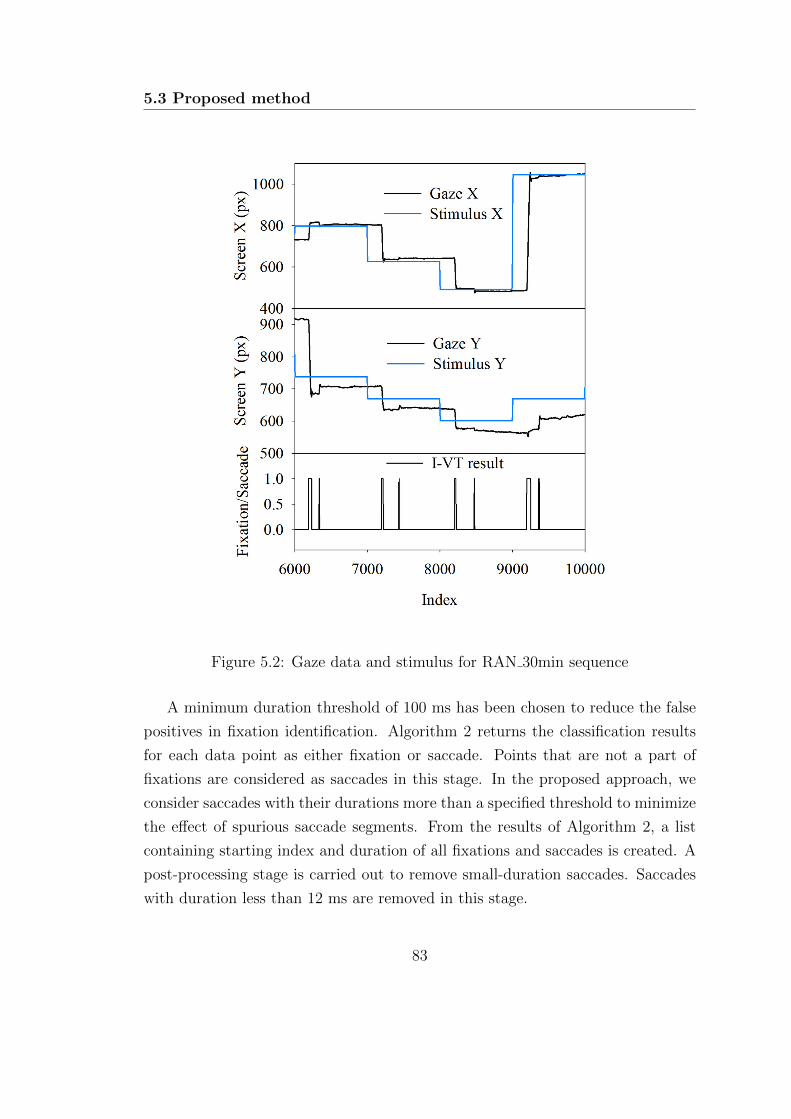
5.3 Proposed method
Figure 5.2: Gaze data and stimulus for RAN 30min sequence
A minimum duration threshold of 100 ms has been chosen to reduce the false
positives in fixation identification. Algorithm 2 returns the classification results
for each data point as either fixation or saccade. Points that are not a part of
fixations are considered as saccades in this stage. In the proposed approach, we
consider saccades with their durations more than a specified threshold to minimize
the effect of spurious saccade segments. From the results of Algorithm 2, a list
containing starting index and duration of all fixations and saccades is created. A
post-processing stage is carried out to remove small-duration saccades. Saccades
with duration less than 12 ms are removed in this stage.
83

Eye Movement based Biometric Authentication
5.3.3.2 Feature extraction
After the removal of small-duration saccades, each eye movement data is arranged
into a sequence of fixations and saccades. The sequence of gaze locations and cor-
responding visual angles are also available for each fixation and saccade. Several
statistical features are extracted from the position, velocity and acceleration pro-
files of the gaze sequence. Other features like duration, dispersion, path length and
co-occurrence features are also extracted for both fixations and saccades. Earlier
works [123] suggested that saccades provide a rich amount of information about
the dynamics of the oculomotor plant. Hence, we extract several other parame-
ters including the saccadic ratio, main sequence, angle, etc. Saccades in horizontal
and vertical directions are generated by different areas of the brain [139]. We use
the statistical properties of the gaze data in x and y directions to incorporate
this information. The distance and angle with the previous fixation/saccade are
also used as features to leverage the temporal properties. The method used for
computation of features is described below.
Figure 5.3: Classification of the raw sequence
Figure. 5.3 depicts the time series of x and y positions of gaze. The dotted red
rectangles denote the saccade sections segmented out using the I-VT algorithm.
84
5.3 Proposed method
The region between two saccade regions constitutes a fixation. For each fixation or
saccade segment we represent, the fixation or saccade using sets of x coordinates
and y coordinates as X and Y .
Let X = {x1, x2, x3, ..., xN} and Y = {y1, y2, y3, ..., yN} denote the set of
coordinate positions of gaze in each fixation/saccade and let N denotes the number
of data points in any fixation or saccade. (xi, yi) denotes gaze location on the
screen coordinate system and (θxi , θyi ) denotes the corresponding horizontal and
vertical visual angles.
A large number of features are extracted from the gaze sequence in each fix-
ation and saccade. Some features are derived from the angular velocity. The
differentiation operation for finding velocity and acceleration is carried out using
forward difference method on the smoothed data. List of features extracted from
fixations and saccades along with the methods of computation are shown in Table
5.1 and Table 5.2. The features are extracted independently for each fixation and
saccade.
The control mechanisms generating fixations and saccades are different. The
number of fixations and saccades is also different in each recording. There is a
total of 12 and 46 features extracted from fixations and saccades respectively. A
feature normalization scheme is used to scale each feature into a common range
to ensure equal contribution in the final classification stage.
5.3.3.3 Feature selection
The large number of features extracted may contain redundancy and correlation.
A backward feature selection algorithm, as shown in Algorithm 3 is used to retain
a minimal set of discriminant features. We use the wrapper-based approach [140]
for selecting the features. An RBFN classifier is used for finding the Equal Error
Rate (EER) in each iteration. Cross-validation has been carried out in the training
set to avoid overfitting. We used a random 50% subset of the development dataset
for the feature selection algorithm. Feature selection algorithm starts with a set
of all the features. Now in each iteration, the EER with inclusion and exclusion
of a particular feature is found. The feature is retained if the EER with the use
of the feature is better than EER with exclusion. The procedure is repeated for
85

Eye Movement based Biometric Authentication
Tab
le5.1:
List
offeatu
resex
tractedfrom
fixation
sU
sedin
Fix
ationfeatu
resD
escription
TE
XR
AN
NY
Fix
ationduration
Obtain
edfrom
I-VT
result
NN
Stan
dard
dev
iation(X
)F
romscreen
coord
inates
durin
gfixation
YN
Stan
dard
dev
iation(Y
)”
YY
Path
length
Len
gthof
path
traveledin
screen
PathLength
=N−1
∑i=1 √
(xi+
1 −xi )2
+(yi+
1 −yi )2
YY
Angle
with
prev
ious
fixation
Angle
with
centroid
ofprev
ious
fixation
YY
Distan
cefrom
the
lastfixation
Euclid
eandistan
cefrom
the
prev
ious
fixation
YY
Skew
ness(X
)F
romScreen
coord
inates
YY
Skew
ness(Y
)”
NN
Kurtosis(X
)”
YY
Kurtosis(Y
)”
YY
Disp
ersionSpatial
spread
durin
ga
fixation
,C
omputed
asD
=(m
ax(X
)−min
(X))
+(m
ax(Y
)−min
(Y))
YY
Average
velocity
AV
=ppa
thlen
gth/duration
Yan
dN
den
otein
clusion
orex
clusion
ofth
efeatu
rein
the
particu
larstim
ulu
safter
feature
selection
86

5.3 Proposed method
Tab
le5.
2:L
ist
offe
ature
sex
trac
ted
from
sacc
ades
Use
din
Sac
cade
feat
ure
sD
escr
ipti
onT
EX
RA
NN
NSac
cadic
dura
tion
Obta
ined
from
I-V
Tre
sult
YY
Dis
per
sion
D=
(max
(X)−min
(X))
+(m
ax(Y
)−min
(Y))
NY
YY
YY
NN
NY
YY
M3S
2K(a
ngu
lar
velo
city
)F
eatu
res
from
angu
lar
velo
city
YY
YY
YN
YY
YY
YY
M3S
2K(a
ngu
lar
acce
lera
tion
)F
eatu
res
from
angu
lar
acce
lera
tion
YY
Sta
ndar
ddev
iati
on(X
)O
bta
ined
from
scre
enp
osit
ions
YY
Sta
ndar
ddev
iati
on(Y
)”
YY
Pat
hle
ngt
hD
ista
nce
trav
eled
insc
reen
,N−1 ∑ i=1
√ (xi+
1−xi)2
+(yi+
1−y i
)2
YY
Angl
ew
ith
pre
vio
us
sacc
ade
Diff
eren
cein
sacc
adic
angl
ew
ith
pre
vio
us
sacc
ade
YY
Dis
tance
from
the
pre
vio
us
sacc
ade
Eucl
idea
ndis
tance
bet
wee
nth
ece
ntr
oid
ofth
epre
vio
us
sacc
ade
YY
Sac
cadic
rati
oSR
=m
ax(angularvelocity)/saccadeduration
YY
Sac
cade
angl
eO
bta
ined
from
firs
tan
dla
stp
oints
as,saccadeangle
=ta
n−1( y N−
y1
xN−x1
)Y
YSac
cade
amplitu
de
Obta
ined
as:√ (x
N−x1)2
+(yN−y 1
)2
YY
YY
YY
YY
YY
YY
M3S
2K(V
eloci
tyX
dir
ecti
on)
Fea
ture
sfr
omsc
reen
pos
itio
ns
YY
YY
YY
YY
YY
NY
M3S
2K(V
eloci
tyY
dir
ecti
on)
”Y
YY
YY
YY
YY
YY
YM
3S2K
(Acc
eler
atio
nX
dir
ecti
on)
”Y
YY
YY
YY
YN
YY
YM
3S2K
(Acc
eler
atio
nY
dir
ecti
on)
”
*M3S
2K-
Sta
tist
ical
feat
ure
s:M
ean,M
edia
n,M
ax,S
td,
Ske
wnes
s,K
urt
osis
Yan
dN
den
ote
incl
usi
onor
excl
usi
onof
the
feat
ure
inth
epar
ticu
lar
stim
ulu
saf
ter
feat
ure
sele
ctio
n
87
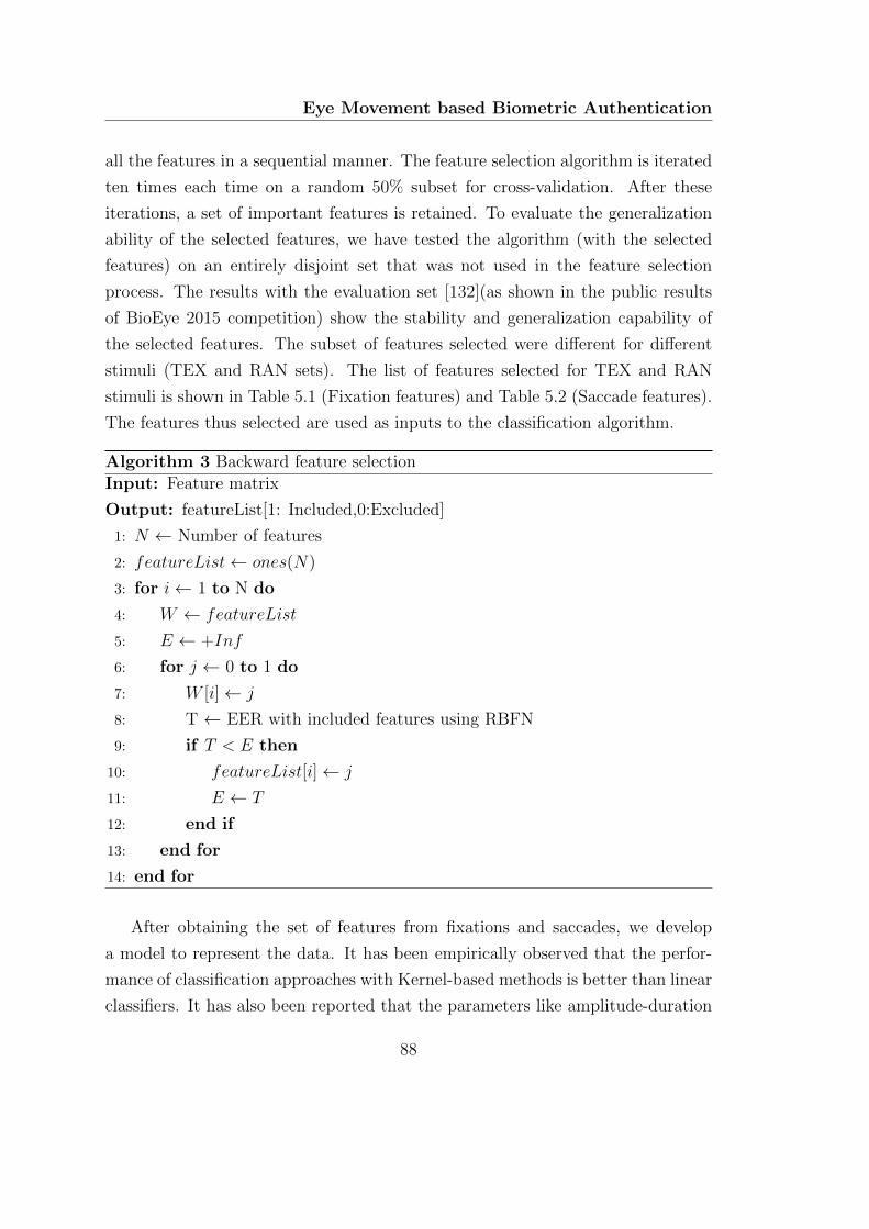
Eye Movement based Biometric Authentication
all the features in a sequential manner. The feature selection algorithm is iterated
ten times each time on a random 50% subset for cross-validation. After these
iterations, a set of important features is retained. To evaluate the generalization
ability of the selected features, we have tested the algorithm (with the selected
features) on an entirely disjoint set that was not used in the feature selection
process. The results with the evaluation set [132](as shown in the public results
of BioEye 2015 competition) show the stability and generalization capability of
the selected features. The subset of features selected were different for different
stimuli (TEX and RAN sets). The list of features selected for TEX and RAN
stimuli is shown in Table 5.1 (Fixation features) and Table 5.2 (Saccade features).
The features thus selected are used as inputs to the classification algorithm.
Algorithm 3 Backward feature selectionInput: Feature matrix
Output: featureList[1: Included,0:Excluded]
1: N ← Number of features
2: featureList← ones(N)
3: for i← 1 to N do
4: W ← featureList
5: E ← +Inf
6: for j ← 0 to 1 do
7: W [i]← j
8: T ← EER with included features using RBFN
9: if T < E then
10: featureList[i]← j
11: E ← T
12: end if
13: end for
14: end for
After obtaining the set of features from fixations and saccades, we develop
a model to represent the data. It has been empirically observed that the perfor-
mance of classification approaches with Kernel-based methods is better than linear
classifiers. It has also been reported that the parameters like amplitude-duration
88
5.3 Proposed method
and amplitude-peak velocity may vary with the angle of saccade [141]. The na-
ture of saccade dynamics may be different in different directions as the stimulus is
changing randomly at various points on the screen. For each person, saccades of
different amplitudes and directions form clusters in the feature space. In order to
use the multi-mode nature of the data, we represent them by clustering them in the
feature space. Representative vectors from each cluster are used to characterize
each person. We use Gaussian radial basis function network (GRBFN) to model
these data. The multiple cluster centers in the feature space are used as repre-
sentative vectors in this approach. These vectors are selected using the K -means
algorithm. Two different RBFNs are trained separately for fixation and saccade.
Details about the structure of network and score fusion stage are described in the
following section.
5.3.4 RBF network
Radial basis function network (RBFN) is a class of neural networks initially pro-
posed by Broomhead and Lowe [142]. Classification in RBFN is done by calculat-
ing the similarity between training and test vectors. Multiple prototype vectors
corresponding to each class are stored in each neuron. The Euclidean distance
between the input vector and the prototype vector is used to calculate neuron
activations.
In the RBF network, input layer is made of feature vectors (Fig. 5.4). ϕ(x) is
a radial basis function that finds the Euclidean distance between the input vector
and the prototype vector. A weighted combination of scores from the RBF layer
is used to classify the input into different categories.
The number of prototypes per class can be defined by the user, and these
vectors can be found from the data using different algorithms like K -means,
Linde–Buzo–Gray (LBG) algorithm, etc.
The Gaussian activation function of each neuron is chosen as:
ϕ(x) = e−β‖x−µ‖2
(5.3)
where, µ is the mean of the distribution. The parameter β can be found from the
data.
89
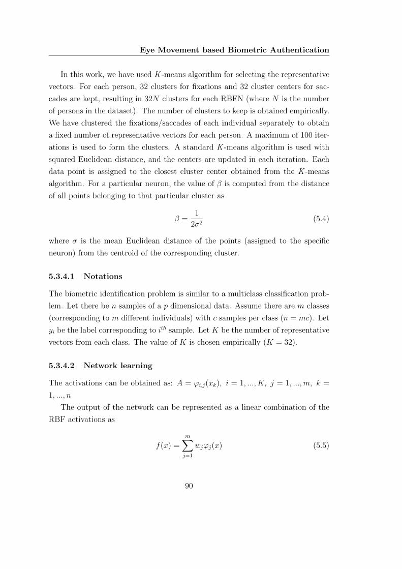
Eye Movement based Biometric Authentication
In this work, we have used K -means algorithm for selecting the representative
vectors. For each person, 32 clusters for fixations and 32 cluster centers for sac-
cades are kept, resulting in 32N clusters for each RBFN (where N is the number
of persons in the dataset). The number of clusters to keep is obtained empirically.
We have clustered the fixations/saccades of each individual separately to obtain
a fixed number of representative vectors for each person. A maximum of 100 iter-
ations is used to form the clusters. A standard K -means algorithm is used with
squared Euclidean distance, and the centers are updated in each iteration. Each
data point is assigned to the closest cluster center obtained from the K -means
algorithm. For a particular neuron, the value of β is computed from the distance
of all points belonging to that particular cluster as
β =1
2σ2(5.4)
where σ is the mean Euclidean distance of the points (assigned to the specific
neuron) from the centroid of the corresponding cluster.
5.3.4.1 Notations
The biometric identification problem is similar to a multiclass classification prob-
lem. Let there be n samples of a p dimensional data. Assume there are m classes
(corresponding to m different individuals) with c samples per class (n = mc). Let
yi be the label corresponding to ith sample. Let K be the number of representative
vectors from each class. The value of K is chosen empirically (K = 32).
5.3.4.2 Network learning
The activations can be obtained as: A = ϕi,j(xk), i = 1, ..., K, j = 1, ...,m, k =
1, ..., n
The output of the network can be represented as a linear combination of the
RBF activations as
f(x) =m∑j=1
wjϕj(x) (5.5)
90
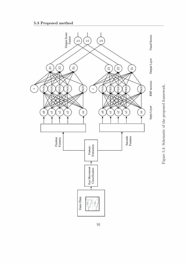
5.3 Proposed method
Fig
ure
5.4:
Sch
emat
icof
the
pro
pos
edfr
amew
ork.
91
Eye Movement based Biometric Authentication
where, f(x) contains the class membership in vector form. Given the activa-
tions and output labels, the objective of the training stage is to find the weight
parameters of the output layer. The weights are obtained by minimizing the sum
of squared errors.
The output layer is represented by a linear system as:
Aw = y (5.6)
The optimal set of weights can be found using the Moore–Penrose pseudoinverse.
Alternatively, these weights can be learned through gradient descent method. In
the learning phase, features extracted from each fixation and saccade are used
to train the model. Each fixation/saccade is treated as a sample in the training
process.
The method described here uses two-phase learning. RBF layer and weight
layer trainings are carried out separately. However, a joint training similar to
back-propagation is also possible [143].
5.3.4.3 Training stage
Only the session 1 data from the datasets are used in the training stage. Clus-
ter centers and corresponding β values are computed separately for each person
(resulting in 32N neurons for both fixation and saccade RBFNs). The output
weights (wfix and wsacc) are found using all fixations and saccades from all the
subjects in the dataset.
5.3.4.4 Testing stage
Session 2 data is used in the testing stage. Parameters of RBFN are computed
separately for fixations and saccades in the training session. The scores from both
RBFNs are combined to obtain the final result. The overall configuration of the
scheme is shown in Fig. 5.4.
For an unlabeled probe, the activations for each fixation and saccade (Afix
and Asacc) are found separately using the cluster centers obtained in the training
stage. The final classification is carried out using the combined score obtained
92
5.4 Experiments and results
from all saccades and fixations. Let nfix and nsacc be the number of fixations and
saccades in an unlabeled gaze sequence. The combined score can be obtained as:
score = λ1
nfix
nfix∑i=1
Aifixwfix + (1− λ)1
nsacc
nsacc∑i=1
Aisaccwsacc (5.7)
where, λ ∈ [0 1] is the weight used in the score fusion. The parameter λ decides
the contribution of fixations and saccades in the final decision stage. This value
can be obtained empirically. In the present work, λ value of 0.5 is used.
The label of the unknown sample can be obtained as
label = arg maxm
(score) (5.8)
5.4 Experiments and results
5.4.1 Datasets
The data used in this work are part of the development phase of BioEye 2015
[132] competition. Data recorded in three different sessions are available. First
two sessions are separated by a time interval of 30 min containing recordings of
153 subjects (ages 18-43). A third session, conducted after one year, (37 subjects)
is also available to evaluate the robustness against template aging. The database
contains gaze sequences obtained using two distinct types of visual stimuli. In one
set (RAN), a white dot moving in a dark background was used as the stimulus.
The subjects were asked to follow the dot. Text excerpt shown on the screen was
used as the stimulus in the other set (TEX). The samples were recorded with
an EyeLink eye-tracker (with a reported spatial accuracy of 0.5 degrees) at 1000
Hz and down-sampled to 250 Hz with anti-aliasing filtering. The development
dataset contains the ground truth about the identity of the persons. An additional
evaluation set is also available without ground truth.
In each recording, visual angles in x and y direction, stimulus angle in x and
y direction and information regarding the validity of the samples are available.
Details about the stimulus types in BioEye 2015 database are given below.
93
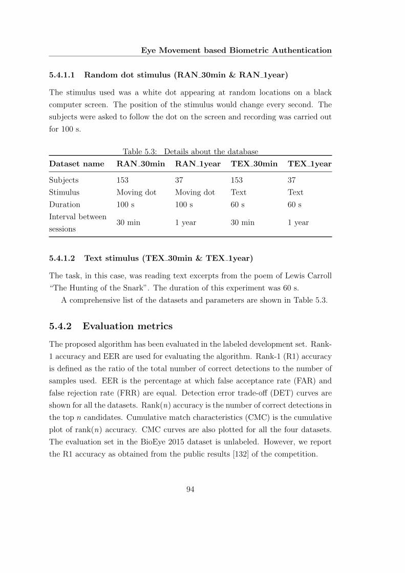
Eye Movement based Biometric Authentication
5.4.1.1 Random dot stimulus (RAN 30min & RAN 1year)
The stimulus used was a white dot appearing at random locations on a black
computer screen. The position of the stimulus would change every second. The
subjects were asked to follow the dot on the screen and recording was carried out
for 100 s.
Table 5.3: Details about the database
Dataset name RAN 30min RAN 1year TEX 30min TEX 1year
Subjects 153 37 153 37
Stimulus Moving dot Moving dot Text Text
Duration 100 s 100 s 60 s 60 s
Interval between
sessions30 min 1 year 30 min 1 year
5.4.1.2 Text stimulus (TEX 30min & TEX 1year)
The task, in this case, was reading text excerpts from the poem of Lewis Carroll
“The Hunting of the Snark”. The duration of this experiment was 60 s.
A comprehensive list of the datasets and parameters are shown in Table 5.3.
5.4.2 Evaluation metrics
The proposed algorithm has been evaluated in the labeled development set. Rank-
1 accuracy and EER are used for evaluating the algorithm. Rank-1 (R1) accuracy
is defined as the ratio of the total number of correct detections to the number of
samples used. EER is the percentage at which false acceptance rate (FAR) and
false rejection rate (FRR) are equal. Detection error trade-off (DET) curves are
shown for all the datasets. Rank(n) accuracy is the number of correct detections in
the top n candidates. Cumulative match characteristics (CMC) is the cumulative
plot of rank(n) accuracy. CMC curves are also plotted for all the four datasets.
The evaluation set in the BioEye 2015 dataset is unlabeled. However, we report
the R1 accuracy as obtained from the public results [132] of the competition.
94
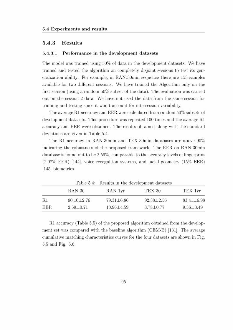
5.4 Experiments and results
5.4.3 Results
5.4.3.1 Performance in the development datasets
The model was trained using 50% of data in the development datasets. We have
trained and tested the algorithm on completely disjoint sessions to test its gen-
eralization ability. For example, in RAN 30min sequence there are 153 samples
available for two different sessions. We have trained the Algorithm only on the
first session (using a random 50% subset of the data). The evaluation was carried
out on the session 2 data. We have not used the data from the same session for
training and testing since it won’t account for intersession variability.
The average R1 accuracy and EER were calculated from random 50% subsets of
development datasets. This procedure was repeated 100 times and the average R1
accuracy and EER were obtained. The results obtained along with the standard
deviations are given in Table 5.4.
The R1 accuracy in RAN 30min and TEX 30min databases are above 90%
indicating the robustness of the proposed framework. The EER on RAN 30min
database is found out to be 2.59%, comparable to the accuracy levels of fingerprint
(2.07% EER) [144], voice recognition systems, and facial geometry (15% EER)
[145] biometrics.
Table 5.4: Results in the development datasets
RAN 30 RAN 1yr TEX 30 TEX 1yr
R1 90.10±2.76 79.31±6.86 92.38±2.56 83.41±6.98
EER 2.59±0.71 10.96±4.59 3.78±0.77 9.36±3.49
R1 accuracy (Table 5.5) of the proposed algorithm obtained from the develop-
ment set was compared with the baseline algorithm (CEM-B) [131]. The average
cumulative matching characteristics curves for the four datasets are shown in Fig.
5.5 and Fig. 5.6.
95
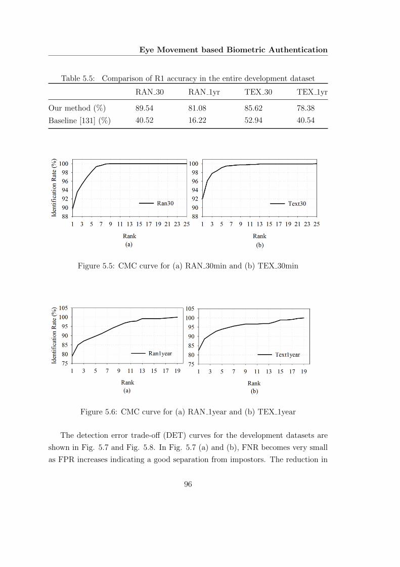
Eye Movement based Biometric Authentication
Table 5.5: Comparison of R1 accuracy in the entire development dataset
RAN 30 RAN 1yr TEX 30 TEX 1yr
Our method (%) 89.54 81.08 85.62 78.38
Baseline [131] (%) 40.52 16.22 52.94 40.54
Figure 5.5: CMC curve for (a) RAN 30min and (b) TEX 30min
Figure 5.6: CMC curve for (a) RAN 1year and (b) TEX 1year
The detection error trade-off (DET) curves for the development datasets are
shown in Fig. 5.7 and Fig. 5.8. In Fig. 5.7 (a) and (b), FNR becomes very small
as FPR increases indicating a good separation from impostors. The reduction in
96
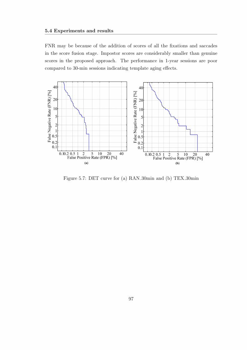
5.4 Experiments and results
FNR may be because of the addition of scores of all the fixations and saccades
in the score fusion stage. Impostor scores are considerably smaller than genuine
scores in the proposed approach. The performance in 1-year sessions are poor
compared to 30-min sessions indicating template aging effects.
Figure 5.7: DET curve for (a) RAN 30min and (b) TEX 30min
97

Eye Movement based Biometric Authentication
Figure 5.8: DET curve for (a) RAN 1year and (b) TEX 1year
5.4.3.2 Performance in the evaluation sets
The evaluation part of the database is unlabeled. However, the results of the
competition are available on the website [132]. The evaluation set of the dataset
had only one unlabeled data for every labeled sample. We have used this one to
one correspondence assumption in the final stage of the algorithm.
Let there be n labeled and n unlabeled recordings. The task is to assign
each unlabeled file to a labeled file. The scores obtained from RBF output stage
were stored in a matrix D (with dimension nxn). D(i, j) denotes the normalized
similarity score between ith labeled and jth unlabeled samples. We have selected
the best match for each unlabeled recording using Algorithm 4. The use of this
one to one assumption improved the results. However, this assumption may not be
suitable for practical biometric identification/verification scenarios. The proposed
method has been found to outperform all the other methods even without the
one to one assumption indicating the robustness for biometric applications. The
results with and without this assumption are shown in Table 5.6.
98
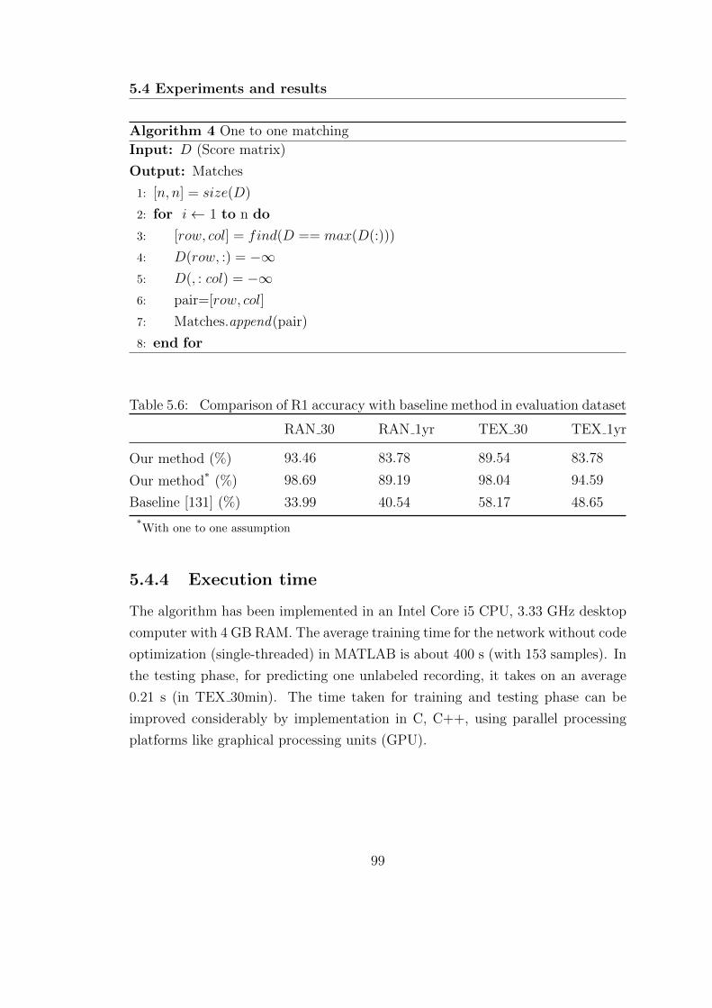
5.4 Experiments and results
Algorithm 4 One to one matching
Input: D (Score matrix)
Output: Matches
1: [n, n] = size(D)
2: for i← 1 to n do
3: [row, col] = find(D == max(D(:)))
4: D(row, :) = −∞5: D(, : col) = −∞6: pair=[row, col]
7: Matches.append(pair)
8: end for
Table 5.6: Comparison of R1 accuracy with baseline method in evaluation dataset
RAN 30 RAN 1yr TEX 30 TEX 1yr
Our method (%) 93.46 83.78 89.54 83.78
Our method* (%) 98.69 89.19 98.04 94.59
Baseline [131] (%) 33.99 40.54 58.17 48.65
*With one to one assumption
5.4.4 Execution time
The algorithm has been implemented in an Intel Core i5 CPU, 3.33 GHz desktop
computer with 4 GB RAM. The average training time for the network without code
optimization (single-threaded) in MATLAB is about 400 s (with 153 samples). In
the testing phase, for predicting one unlabeled recording, it takes on an average
0.21 s (in TEX 30min). The time taken for training and testing phase can be
improved considerably by implementation in C, C++, using parallel processing
platforms like graphical processing units (GPU).
99
Eye Movement based Biometric Authentication
5.4.5 Discussions
5.4.5.1 Performance of the algorithm
The R1 accuracy of the proposed method is high in both TEX and RAN datasets,
which indicates the possibility of developing a task-independent biometric system.
The EER and R1 accuracy achieved show the robustness of the proposed score
fusion approach. The selected features show good discrimination ability in both
stimuli. The accuracy with 1-year datasets is comparatively lesser than that with
the 30-min datasets. This lower accuracy may be attributed to template aging
effects. Some of the selected features may show variability over time [146] [147].
The amplitudes and directions of the saccades were random in the RAN dataset.
This indicates that once we have a proper enrollment done, biometric identifica-
tion can be performed just by using the eye movements during natural interaction
conditions, even without the cooperation of subjects (as there are no restrictions
on amplitude or direction). The normal eye movement during normal daily tasks
can be used for the authentication purposes.
The feature selection was carried out in 30-min datasets due to the availability
of a large number of subjects. Feature selection with 1-year datasets may lead
to overfitting because of fewer subjects. This issue can be solved by using the
feature selection in 1-year datasets with a larger number of subjects, which may
identify features that are robust against template aging. However, the results show
significant improvement compared to the state of the art methods. The proposed
algorithm was ranked first in the BioEye 2015 [132] competition.
5.4.5.2 Limitations
Controlled experimental setup was used to collect the data used in this work. The
sampling rate and quality of data used in the present work were very high since
it was collected in lab conditions using chinrest. It is to be noted that the data
used in this work was captured at 1000 Hz. The performance of the algorithm at
lower sampling rates needs to be evaluated further. Accurate estimation of the
features in noisy, low sampling rates is necessary for the use in a practical biometric
scenario. The nature of eye movements may be affected by the level of alertness,
fatigue, emotions, cognitive loading, etc. Consumption of caffeine and alcohol by
100
5.5 Summary
the subjects may affect the performance of the proposed algorithm. The features
selected for biometrics should be invariant to such variations. Only two sessions
of data were available for each subject. Intersession variability and template aging
effects need to be studied further. Lack of publicly available databases containing a
large number of samples (to account for template aging, uncontrolled environment,
affective states, intersession variability) is another problem. Creation of a large
database with such variability could provide more robust solutions.
5.5 Summary
A novel framework for biometric identification based on dynamic characteristics
of eye movements is proposed in this chapter. The raw eye movement data is
classified into a sequence of fixations and saccades. We extract a large set of fea-
tures from fixations and saccades to characterize each individual. The important
features extracted from fixations and saccades are identified based on a backward
selection framework. Two different Gaussian RBF networks are trained using
features from fixations and saccades separately. In the detection phase, scores
obtained from both RBF networks are used to get the subject’s identity. The high
accuracy obtained shows the robustness of the proposed algorithm. The proposed
framework can be easily integrated into the existing iris recognition systems. Even
though iris recognition technology is very accurate, it is susceptible to spoofing. A
high-quality printout of an NIR iris pattern printed on a contact lens worn by an
impostor can spoof the system. Incorporating eye movement features along with
iris recognition systems might make spoofing attacks impractical. A combination
of the proposed approach with conventional iris recognition systems may give rise
to a new counterfeit-resistant biometric system. The comparable accuracy in dis-
tinct types of stimuli indicates the possibility of developing a task-independent
system for eye movement biometrics. The proposed method can also be used for
continuous authentication in desktop environments.
101

C H A P T E R 6
Activity Recognition from Head
Mounted Eye Tracker
This chapter presents a framework for recognition of human activity from
egocentric video and eye tracking data obtained from a head-mounted eye
tracker. Three channels of information such as eye movement, ego-motion,
and visual features are combined for the classification of activities. Image
features were extracted using a pre-trained convolutional neural network. Eye
and ego-motion are quantized, and the windowed histograms are used as the
features. The combination of features obtains better accuracy for activity
classification as compared to individual features [148].
6.1 Introduction
Activity recognition from videos is an important topic in computer vision com-
munity. Recognition of actions has several applications in many areas such as
human-computer interaction (HCI), robotics, surveillance, image and video re-
trieval. Most of the literature in this field deals with action recognition from video
103
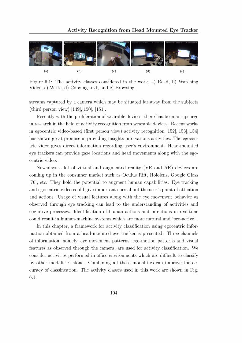
Activity Recognition from Head Mounted Eye Tracker
Figure 6.1: The activity classes considered in the work, a) Read, b) WatchingVideo, c) Write, d) Copying text, and e) Browsing.
streams captured by a camera which may be situated far away from the subjects
(third person view) [149],[150], [151].
Recently with the proliferation of wearable devices, there has been an upsurge
in research in the field of activity recognition from wearable devices. Recent works
in egocentric video-based (first person view) activity recognition [152],[153],[154]
has shown great promise in providing insights into various activities. The egocen-
tric video gives direct information regarding user’s environment. Head-mounted
eye trackers can provide gaze locations and head movements along with the ego-
centric video.
Nowadays a lot of virtual and augmented reality (VR and AR) devices are
coming up in the consumer market such as Oculus Rift, Hololens, Google Glass
[76], etc. They hold the potential to augment human capabilities. Eye tracking
and egocentric video could give important cues about the user’s point of attention
and actions. Usage of visual features along with the eye movement behavior as
observed through eye tracking can lead to the understanding of activities and
cognitive processes. Identification of human actions and intentions in real-time
could result in human-machine systems which are more natural and ‘pro-active’ .
In this chapter, a framework for activity classification using egocentric infor-
mation obtained from a head-mounted eye tracker is presented. Three channels
of information, namely, eye movement patterns, ego-motion patterns and visual
features as observed through the camera, are used for activity classification. We
consider activities performed in office environments which are difficult to classify
by other modalities alone. Combining all these modalities can improve the ac-
curacy of classification. The activity classes used in this work are shown in Fig.
6.1.
104
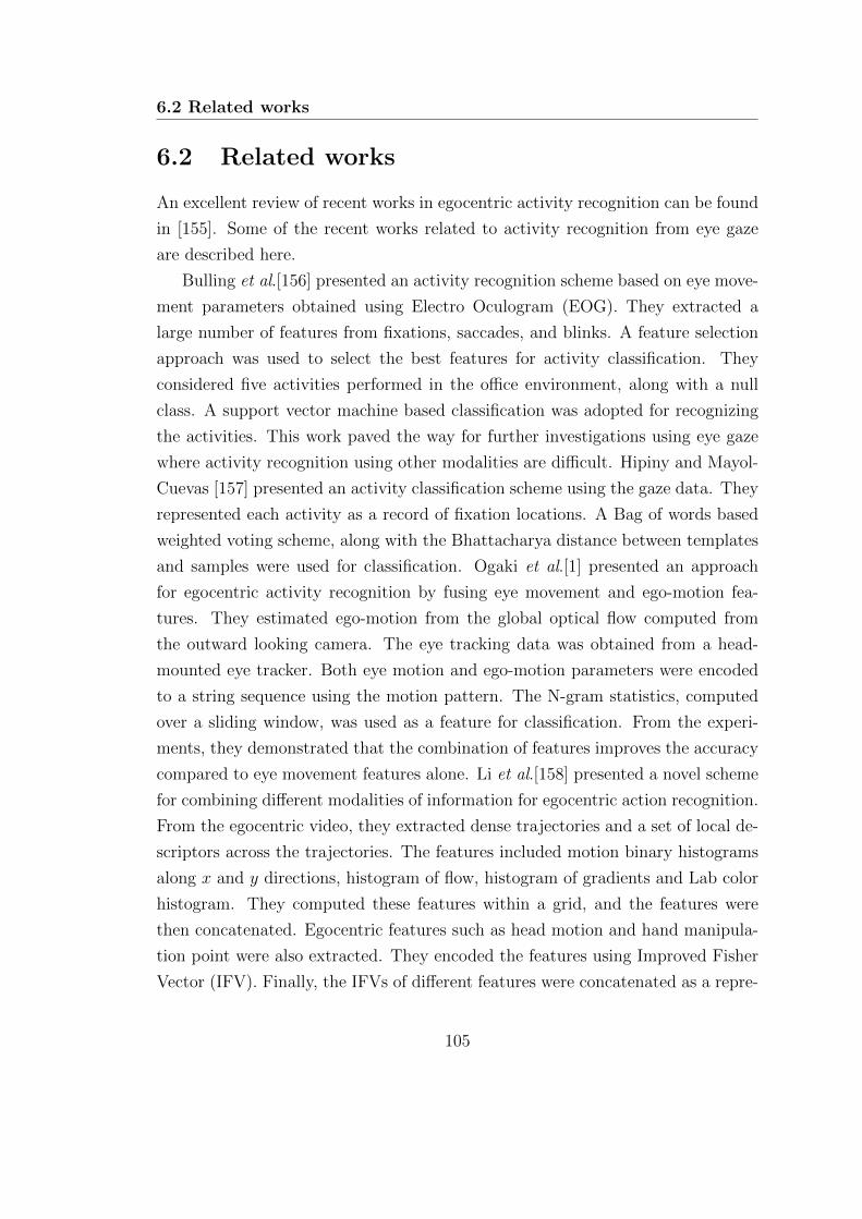
6.2 Related works
6.2 Related works
An excellent review of recent works in egocentric activity recognition can be found
in [155]. Some of the recent works related to activity recognition from eye gaze
are described here.
Bulling et al.[156] presented an activity recognition scheme based on eye move-
ment parameters obtained using Electro Oculogram (EOG). They extracted a
large number of features from fixations, saccades, and blinks. A feature selection
approach was used to select the best features for activity classification. They
considered five activities performed in the office environment, along with a null
class. A support vector machine based classification was adopted for recognizing
the activities. This work paved the way for further investigations using eye gaze
where activity recognition using other modalities are difficult. Hipiny and Mayol-
Cuevas [157] presented an activity classification scheme using the gaze data. They
represented each activity as a record of fixation locations. A Bag of words based
weighted voting scheme, along with the Bhattacharya distance between templates
and samples were used for classification. Ogaki et al.[1] presented an approach
for egocentric activity recognition by fusing eye movement and ego-motion fea-
tures. They estimated ego-motion from the global optical flow computed from
the outward looking camera. The eye tracking data was obtained from a head-
mounted eye tracker. Both eye motion and ego-motion parameters were encoded
to a string sequence using the motion pattern. The N-gram statistics, computed
over a sliding window, was used as a feature for classification. From the experi-
ments, they demonstrated that the combination of features improves the accuracy
compared to eye movement features alone. Li et al.[158] presented a novel scheme
for combining different modalities of information for egocentric action recognition.
From the egocentric video, they extracted dense trajectories and a set of local de-
scriptors across the trajectories. The features included motion binary histograms
along x and y directions, histogram of flow, histogram of gradients and Lab color
histogram. They computed these features within a grid, and the features were
then concatenated. Egocentric features such as head motion and hand manipula-
tion point were also extracted. They encoded the features using Improved Fisher
Vector (IFV). Finally, the IFVs of different features were concatenated as a repre-
105

Activity Recognition from Head Mounted Eye Tracker
sentation of the video. Support vector machine (SVM) was used for classification.
However, they did not use eye movement patterns in their framework. Fathi et
al.[159] demonstrated the relation between the task being performed and the lo-
cations of visual attention. They showed that the information regarding hand-eye
coordination could be beneficial in two different scenarios, predicting the probable
gaze sequence given an action and predicting the likely action given the gaze se-
quence. Shiga et al.[160] proposed a method for egocentric activity recognition by
combining eye motion and visual features. The eye movement feature extraction
scheme was similar to the method used in [156]. They used N-gram statistics com-
puted over sliding windows. The visual features were obtained by selecting a patch
around the gaze location and extracting local features using SIFT-PCA and dense
sampling. A Bag of words approach was used for the classification. They trained
separate multi-class SVMs for visual and eye movement features, and score fusion
methodology was adopted for the final activity classification. Yan et al.[154] pro-
posed a multi-task clustering approach for egocentric activity classification. They
proposed two different algorithms for activity classification in unsupervised set-
tings. Kunze et al.[161] provided a description of possibilities of eye tracking in
various use cases such as detection of fatigue and reading. Data from mobile eye
trackers can be utilized for the analysis of reading habits, type of document read,
reading speed comprehension level and identifying alertness levels.
While there are many approaches for activity classification in egocentric videos,
classification in indoor environments is still a challenge. This can be mainly at-
tributed to the lack of significant motion patterns and limited variations in the
environment. In most of the office activities (like reading, copying, browsing,
watching a video, writing ), the variability in image background, as observed from
the egocentric video is limited. This yields poor accuracy due to the lack of suffi-
cient discriminative information. However, a fusion of these features could improve
the performance. The visual features can provide a context for the action, and
the combination of ego-motion and eye movement pattern can result in better
accuracy in the overall classification.
106
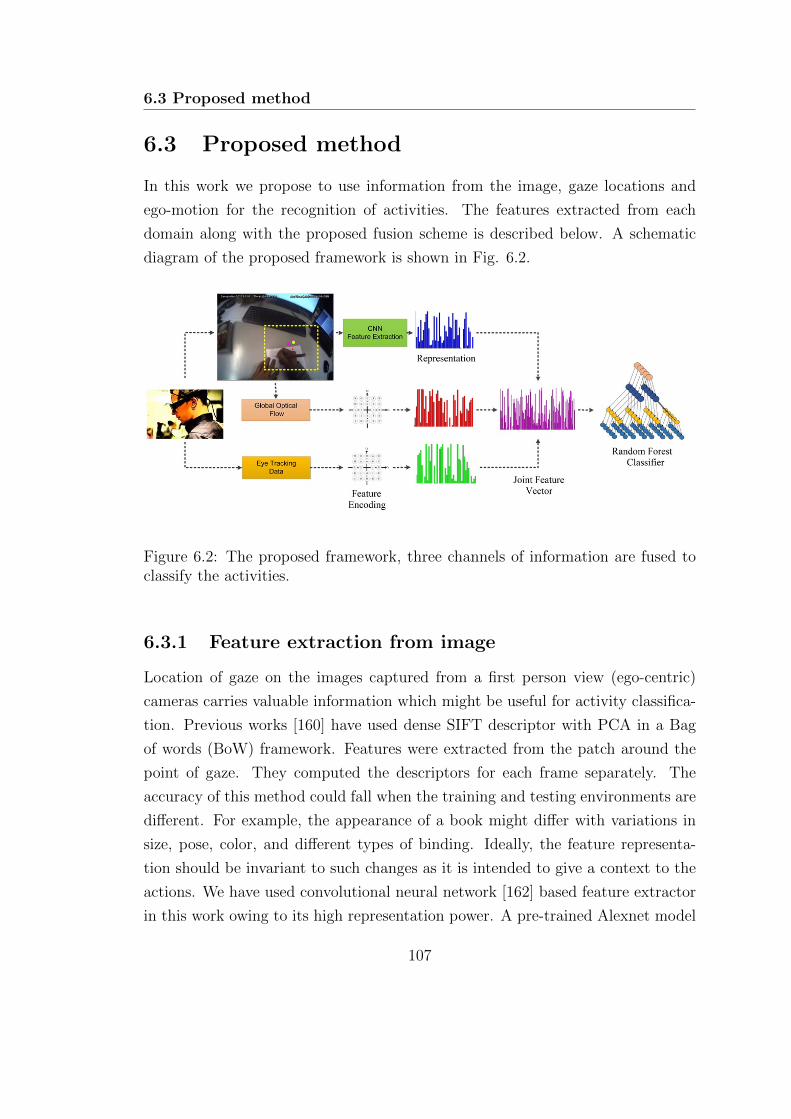
6.3 Proposed method
6.3 Proposed method
In this work we propose to use information from the image, gaze locations and
ego-motion for the recognition of activities. The features extracted from each
domain along with the proposed fusion scheme is described below. A schematic
diagram of the proposed framework is shown in Fig. 6.2.
Figure 6.2: The proposed framework, three channels of information are fused toclassify the activities.
6.3.1 Feature extraction from image
Location of gaze on the images captured from a first person view (ego-centric)
cameras carries valuable information which might be useful for activity classifica-
tion. Previous works [160] have used dense SIFT descriptor with PCA in a Bag
of words (BoW) framework. Features were extracted from the patch around the
point of gaze. They computed the descriptors for each frame separately. The
accuracy of this method could fall when the training and testing environments are
different. For example, the appearance of a book might differ with variations in
size, pose, color, and different types of binding. Ideally, the feature representa-
tion should be invariant to such changes as it is intended to give a context to the
actions. We have used convolutional neural network [162] based feature extractor
in this work owing to its high representation power. A pre-trained Alexnet model
107
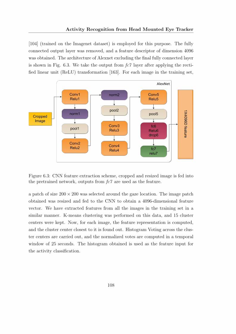
Activity Recognition from Head Mounted Eye Tracker
[104] (trained on the Imagenet dataset) is employed for this purpose. The fully
connected output layer was removed, and a feature descriptor of dimension 4096
was obtained. The architecture of Alexnet excluding the final fully connected layer
is shown in Fig. 6.3. We take the output from fc7 layer after applying the recti-
fied linear unit (ReLU) transformation [163]. For each image in the training set,
Figure 6.3: CNN feature extraction scheme, cropped and resized image is fed intothe pretrained network, outputs from fc7 are used as the feature.
a patch of size 200× 200 was selected around the gaze location. The image patch
obtained was resized and fed to the CNN to obtain a 4096-dimensional feature
vector. We have extracted features from all the images in the training set in a
similar manner. K-means clustering was performed on this data, and 15 cluster
centers were kept. Now, for each image, the feature representation is computed,
and the cluster center closest to it is found out. Histogram Voting across the clus-
ter centers are carried out, and the normalized votes are computed in a temporal
window of 25 seconds. The histogram obtained is used as the feature input for
the activity classification.
108
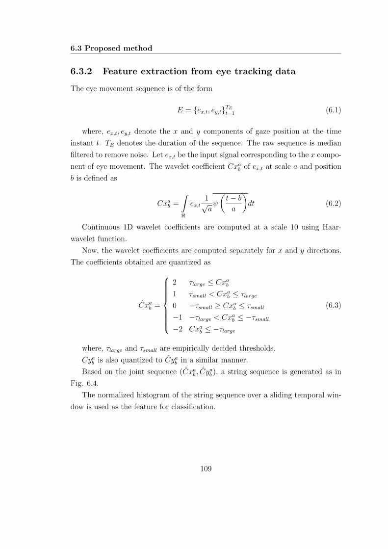
6.3 Proposed method
6.3.2 Feature extraction from eye tracking data
The eye movement sequence is of the form
E = {ex,t, ey,t}TEt=1 (6.1)
where, ex,t, ey,t denote the x and y components of gaze position at the time
instant t. TE denotes the duration of the sequence. The raw sequence is median
filtered to remove noise. Let ex,t be the input signal corresponding to the x compo-
nent of eye movement. The wavelet coefficient Cxab of ex,t at scale a and position
b is defined as
Cxab =
∫<
ex,t1√aψ
(t− ba
)dt (6.2)
Continuous 1D wavelet coefficients are computed at a scale 10 using Haar-
wavelet function.
Now, the wavelet coefficients are computed separately for x and y directions.
The coefficients obtained are quantized as
Cxab =
2 τlarge ≤ Cxab1 τsmall < Cxab ≤ τlarge
0 −τsmall ≥ Cxab ≤ τsmall
−1 −τlarge < Cxab ≤ −τsmall−2 Cxab ≤ −τlarge
(6.3)
where, τlarge and τsmall are empirically decided thresholds.
Cyab is also quantized to Cyab in a similar manner.
Based on the joint sequence (Cxab , Cyab ), a string sequence is generated as in
Fig. 6.4.
The normalized histogram of the string sequence over a sliding temporal win-
dow is used as the feature for classification.
109
Activity Recognition from Head Mounted Eye Tracker
Figure 6.4: Motion encoding scheme.
6.3.3 Feature extraction from motion
Motion features are extracted from the optical flow between subsequent frames.
Let the ith frame be denoted as Fi. For each frame, corner detection is performed to
obtain the candidate points to track. The points are tracked using Lucas-Kanade
optical flow. Successfully tracked points are found out using forward-backward
error [164]. The median flow between the frames can be computed as
∆x = median(δxj), j ∈ [1, K] (6.4)
∆y = median(δyj), j ∈ [1, K] (6.5)
Where K is the number of sparse points tracked between Fi and Fi+1, and δxj
and δyj denote the optical flow of jth point in x and y direction respectively.
Once the global optical flow is obtained, we use a similar encoding scheme as
used for eye gaze data. The histogram of the encoded sequence obtained over a
temporal window is used as the feature for the classification task.
110
6.4 Experiments and results
6.3.4 Fusion and classification framework
Features obtained from the three independent modalities namely ego-motion, eye
gaze features and visual features are combined in the proposed approach. Feature
level fusion [165] is adopted where three modalities are concatenated to form the
final feature vector. We have extracted all the features using a temporal sliding
window of 25 seconds with a stride of one second. Histogram of each independent
feature is computed and concatenated for training the classifier model.
The classification model chosen should be able to handle different types of data
as inputs. We have chosen Random Forest (RF) Classifier for this task. Random
forest algorithm is an ensemble of decision trees initially proposed by Breiman
[166]. It can intrinsically handle multi-class classification problems. Instead of
using a single tree for classification, predictions from a large number of trees are
integrated to form the final prediction. Different trees in the forest are trained
from bootstrap samples. The original data is sampled with replacement and trees
are trained using these bootstrap samples. For each tree, a subset of predictors
are randomly selected at each node and an optimal split is found [167]. The tree is
grown without pruning. In the testing phase, the test sample is fed to N trees in
the forest. Each tree makes a prediction by evaluating the decision tree. The final
prediction is obtained using voting strategy among the outputs of N decision trees.
Random forest is robust to noise and faster to train. RF gives better predictions
without overfitting due to the out of bag error cross-validation used during the
training.
6.4 Experiments and results
Activities performed in office environments are considered in the experiments as
they are difficult to classify by other methods. We have evaluated the accuracy
of individual features as well as joint representation in a multi-class scenario to
assess their performance.
111
Activity Recognition from Head Mounted Eye Tracker
6.4.1 Database used
We have used UTokyo First-Person Activity Recognition Dataset [1] for the eval-
uation task. The dataset contain the data recording of five subjects performing
five different actions in an office environment. The classes available were reading
a book, watching a video, copying text, writing on paper, and internet browsing.
Each of these activities was performed for two minutes. There was a time gap of
thirty seconds (‘Void’ class) between each activity where subjects were allowed to
converse, sing and move freely. Each subject performed the activities twice. The
data from these two sessions were used as the training and test sets. The record-
ings obtained from EMR-9 eye tracking device was also available with the dataset.
For analysis purpose, we have used the eye tracking data and the low-resolution
video (640× 480 resolution) from the dataset.
6.4.2 Experiment protocol
For each subject in the dataset, the features corresponding to visual, eye movement
and ego-motion were extracted from the dataset. For each subject, two separate
instances of the same activity class are available. We have used these two folds for
the evaluations. Initially, the first fold was used for training and the second one
for testing. In the second fold, training and testing sets were interchanged and the
average accuracy computed across these two sets are reported. The evaluations
were performed for a multi-class scenario, data across all subjects were used for
training and testing.
6.4.3 Multi-class classification
We have analyzed the performance with two different scenarios namely five class
and six class classification. In the latter, ‘Void’ class is also used as a valid label.
6.4.3.1 Experiments with five activity classes
We have used five activity classes in this trial. Experiments were performed in
multiclass classification scenario to evaluate the generalization capability of the
features. Training and testing were done across all the individuals. The first
112
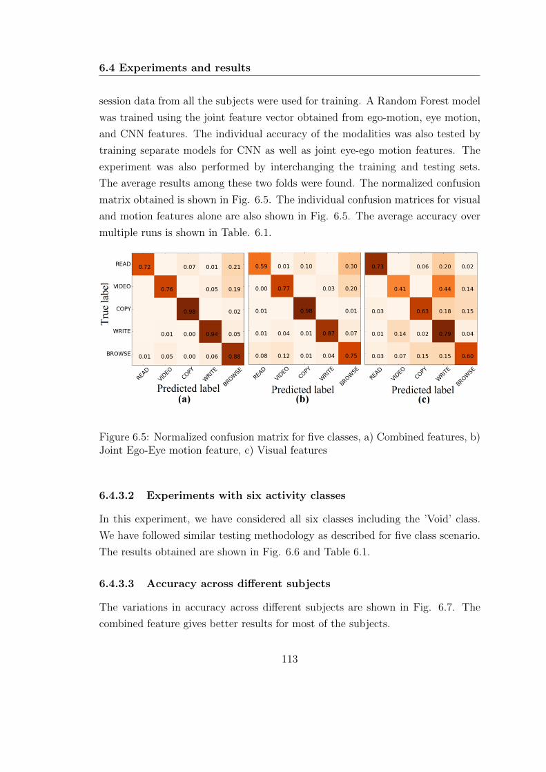
6.4 Experiments and results
session data from all the subjects were used for training. A Random Forest model
was trained using the joint feature vector obtained from ego-motion, eye motion,
and CNN features. The individual accuracy of the modalities was also tested by
training separate models for CNN as well as joint eye-ego motion features. The
experiment was also performed by interchanging the training and testing sets.
The average results among these two folds were found. The normalized confusion
matrix obtained is shown in Fig. 6.5. The individual confusion matrices for visual
and motion features alone are also shown in Fig. 6.5. The average accuracy over
multiple runs is shown in Table. 6.1.
Figure 6.5: Normalized confusion matrix for five classes, a) Combined features, b)Joint Ego-Eye motion feature, c) Visual features
6.4.3.2 Experiments with six activity classes
In this experiment, we have considered all six classes including the ’Void’ class.
We have followed similar testing methodology as described for five class scenario.
The results obtained are shown in Fig. 6.6 and Table 6.1.
6.4.3.3 Accuracy across different subjects
The variations in accuracy across different subjects are shown in Fig. 6.7. The
combined feature gives better results for most of the subjects.
113
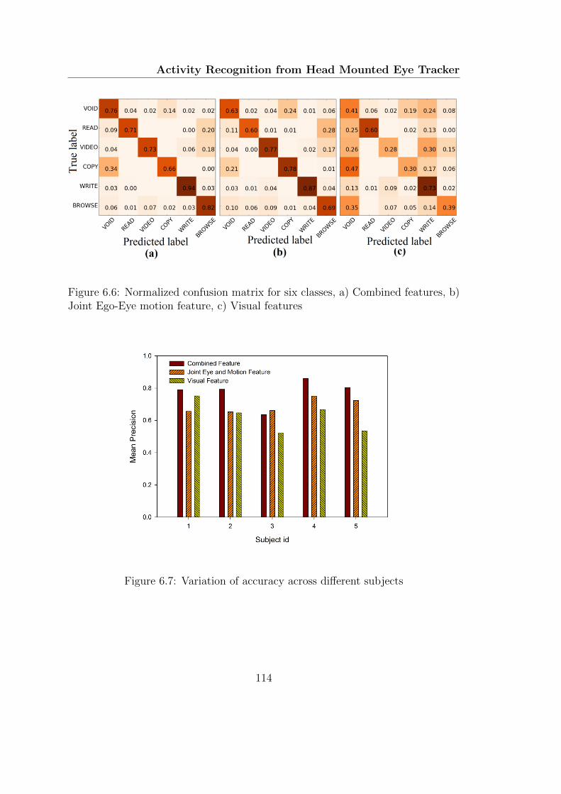
Activity Recognition from Head Mounted Eye Tracker
Figure 6.6: Normalized confusion matrix for six classes, a) Combined features, b)Joint Ego-Eye motion feature, c) Visual features
Figure 6.7: Variation of accuracy across different subjects
114
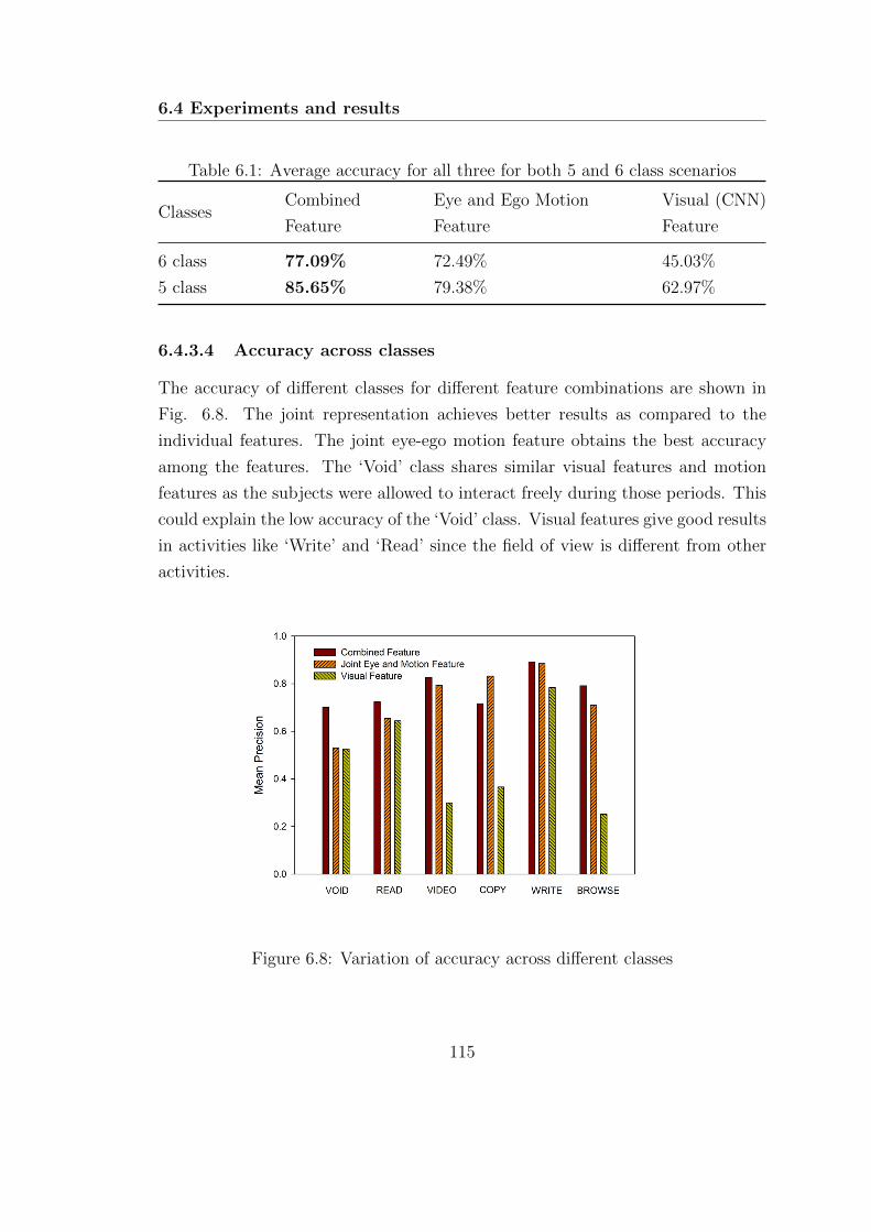
6.4 Experiments and results
Table 6.1: Average accuracy for all three for both 5 and 6 class scenarios
ClassesCombined
Feature
Eye and Ego Motion
Feature
Visual (CNN)
Feature
6 class 77.09% 72.49% 45.03%
5 class 85.65% 79.38% 62.97%
6.4.3.4 Accuracy across classes
The accuracy of different classes for different feature combinations are shown in
Fig. 6.8. The joint representation achieves better results as compared to the
individual features. The joint eye-ego motion feature obtains the best accuracy
among the features. The ‘Void’ class shares similar visual features and motion
features as the subjects were allowed to interact freely during those periods. This
could explain the low accuracy of the ‘Void’ class. Visual features give good results
in activities like ‘Write’ and ‘Read’ since the field of view is different from other
activities.
Figure 6.8: Variation of accuracy across different classes
115
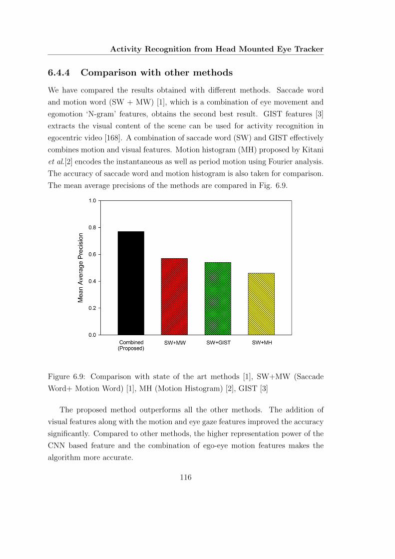
Activity Recognition from Head Mounted Eye Tracker
6.4.4 Comparison with other methods
We have compared the results obtained with different methods. Saccade word
and motion word (SW + MW) [1], which is a combination of eye movement and
egomotion ‘N-gram’ features, obtains the second best result. GIST features [3]
extracts the visual content of the scene can be used for activity recognition in
egocentric video [168]. A combination of saccade word (SW) and GIST effectively
combines motion and visual features. Motion histogram (MH) proposed by Kitani
et al.[2] encodes the instantaneous as well as period motion using Fourier analysis.
The accuracy of saccade word and motion histogram is also taken for comparison.
The mean average precisions of the methods are compared in Fig. 6.9.
Figure 6.9: Comparison with state of the art methods [1], SW+MW (Saccade
Word+ Motion Word) [1], MH (Motion Histogram) [2], GIST [3]
The proposed method outperforms all the other methods. The addition of
visual features along with the motion and eye gaze features improved the accuracy
significantly. Compared to other methods, the higher representation power of the
CNN based feature and the combination of ego-eye motion features makes the
algorithm more accurate.
116
6.4 Experiments and results
6.4.5 Discussions
From the results obtained, it can be seen that the addition of three modalities
improves the accuracy. In six class scenario, highest accuracy is achieved for class
‘Write’. This can be attributed to both distinct gaze patterns as well as visual
features during the activity. Especially, the high accuracy of visual features during
this activity may be due to the appearance of paper and pen which are unique
to this activity. Even though the addition of visual features increases the overall
accuracy, the individual performance of visual features in many cases are poor.
The activities used in this experiment were performed in an office environment,
which does not have much diversity in visual information. The addition of the
Void class introduces more errors as the same visual features appear in multiple
activities.
In the five class scenario, ‘Void’ class was not present. The accuracy of visual
features is much better than the six class case. The overall accuracy of classifica-
tion is also much better in this scenario. The random forest based classifier tries
to identify the important features for activity classification from the joint feature
representation.
Some of the advantages of the proposed system are described here. Three dis-
tinct channels of information are fused in the proposed approach. This improves
the generalizability of the approach for a larger number of classes. Representation
of one particular activity might not require the features from all three channels.
For example, reading has a characteristic pattern as observed from eye tracking
data (sequence of small fixations and saccades), It may be possible to identify
reading activity from eye tracking data alone. Classifying browsing activity from
watching movies might require all three channels of information. The high-level
CNN descriptors used are suitable for giving a context to the actions. The random
forest algorithm is capable of identifying important features which are relevant for
the identification of a particular action. The framework can determine the impor-
tant features required for classifying the activities accurately. Even though the
activity classes used in this work are small, the framework is capable of handling
a large number of classes. The Random Forest based classifier can compute the
features relevant for identifying each action.
117

Activity Recognition from Head Mounted Eye Tracker
6.5 Summary
In this chapter, we have proposed an approach for combining different modalities
such as ego-motion features, eye movement features and visual features for classi-
fication of activities. A joint feature vector is formed from the individual feature
extractors, and a random forest classifier was used to classify the activities using
this joint representation. Joint eye-ego motion feature gave the best individual
accuracy among the features. However, the addition of visual feature resulted in
a higher accuracy in activity classification. Additional channels of information
can be easily added to the framework. The addition of activity-dependent ob-
ject detectors and a weighted fusion of these three modalities might improve the
results.
118
C H A P T E R 7
Conclusion and Future Scope
7.1 Conclusions
This thesis presents the development of gaze tracking algorithms and their appli-
cations in specific areas. The first part of the thesis deals with the development
low-cost eye gaze tracking algorithms for desktop as well as head mounted cam-
eras. In the second part, two applications which leverage the eye tracking data is
developed.
A webcam-based system was developed to bring down the cost of gaze tracking
while maintaining reasonable speed and accuracy. The challenging problem of
iris center localization is solved using an efficient two-stage algorithm. The main
contribution is the simplification of the ellipse fitting problem with a rather simple
two stage scheme using appropriate constraints obtained from the face detection
stage. Another advantage here is that small errors in the first stage can be refined
in the second stage. The algorithm is implemented as a convolutional kernel which
improved its real-time performance. The iris center estimation stage has been
extended to a gaze tracking framework using eye corner detection and tracking.
Pose variations due to in-plane rotations are handled using an affine transformation
of the estimated gaze in the calibration plane. The approach developed achieves
real-time performance in desktop environments.
119
Conclusion and Future Scope
Further, a pupil center localization algorithm is developed for head-mounted
eye trackers. The performance of most of the available algorithms deteriorates
with uncontrolled lighting conditions. We have developed a robust algorithm
for pupil localization in NIR images which works even in challenging conditions.
The algorithm uses either edge based method or grayscale intensity based on the
quality of the image. One significant advantage here is that, even if the first edge
based stage of the algorithm fails due to some reflections, the second stage can
identify the pupil (though more computation is required). Further, the tracking
approach reduces false detection rate at the same time reduces computational
load as the search space is considerably less. Most of the algorithms are designed
to maximize the per frame based detection rates. Here, we have added a simple
tracking framework which directly extends the algorithm for video. The algorithm
had been evaluated in labeled pupils in the wild (LPW) dataset and found to
outperform state of the art methods while achieving real-time performance. The
eye gaze position obtained from such a gaze tracker can be used for various HCI
applications in real-world scenarios.
Classification of gaze direction is useful in various HCI tasks. Further, it
can be used to identify eye accessing cues thereby allowing us to infer various
cognitive processes. The proposed algorithm leverages the information obtained
from the facial landmark detection stage to limit the computation to eye regions.
The alignment using eye corners reduces the intra-class variability. Score level
fusion from the two separately trained CNN’s further improve the accuracy. The
proposed approach achieved superior performance compared to the classical gaze
direction classification methods while obtaining real-time performance.
We have developed algorithms for two applications where eye tracking data is
useful. In the first application, we use eye movement pattern as a biometric modal-
ity. A framework for biometric identification based on eye movements is developed
in this work. A score level fusion approach using a novel set of features extracted
from fixations and saccades are used for biometric authentication. Most of the
features used were extracted from the position, velocity and acceleration profiles
of eye movements. Eye movements are generated from a complex oculomotor
plant, however estimating the parameters of the model directly is difficult. In this
work, we tried to characterize each individual based on the statistical properties
120
7.1 Conclusions
of saccades and fixations of different amplitudes and direction. Important features
were identified using a backward selection framework, and Radial basis function
network was used for classification. The developed framework is evaluated in Bio-
Eye 2015 dataset and was found to outperform state of the art methods. The
proposed approach obtained an average EER of 2.59%. Even though the method
can be used as an independent modality, augmenting eye movement biometrics
with conventional iris recognition technology may lead to a counterfeit resistant
biometric modality with inbuilt liveliness detection and continuous authentication
capabilities. The proposed eye movement based biometrics can complement the
iris based authentication. Iris based authentication is one of the most feasible and
accurate biometric modality available today (with EER close to 0.0011). However,
it is susceptible to spoofing. A high-quality printout of an NIR iris pattern printed
on a contact lens worn by an impostor can spoof the system. Incorporating eye
movement features along with iris recognition systems might make spoofing at-
tacks impractical. The dynamics of eye movements are very fast and complex,
which makes it very difficult to replicate with any mechanical systems.
The second application is the identification of human activities from a head-
mounted eye tracker. Head mounted eye trackers can provide the gaze locations
along with the ego-centric video. The information from various eye movements
and ego-motion are encoded by quantizing the motion. Image features are com-
puted from an image patch centered around the gaze point. A convolutional neural
network based descriptor is used as the feature. Three distinct channels of infor-
mation are fused in the proposed approach. This improves the generalizability of
the approach for a larger number of classes. Representation of one particular ac-
tivity might not require the features from all three channels. The high-level CNN
descriptors used are suitable for giving a context to the actions. The random for-
est algorithm is capable of identifying important features which are relevant for
the identification of a particular action. The proposed approach obtained better
accuracy as compared to state of the art methods.
121
Conclusion and Future Scope
7.2 Limitations and Future scopes
The proposed webcam based gaze estimation framework uses eye corners as the
reference point. This method could fail with large head-pose variations after the
calibration stage. Since the computational overhead from the IC localization stage
is small, complex 3D model based tracking can be employed for pose invariant gaze
estimation. The algorithm proposed for pupil detection in the head mounted track-
ers returns the parameters of the ellipse fitted to the pupil boundary. This ellipse
can be back-projected to determine the variations in pupil diameter. Further,
pupil diameter estimation and its analysis can be useful in identifying affective
and alertness states. The proposed algorithm currently uses a simple tracking
mechanism, however, model-based tracking with explicit eye movement type iden-
tification could improve the performance.
The performance of the proposed eye movement biometrics framework could
be enhanced with score normalizations from different samples. Feature selection
with a larger dataset collected in various sessions could alleviate the template
aging problem. Estimation of the features accurately from noisy, low sampling
rate eye tracking data is another path to be explored.
The activity recognition framework works well for indoor environments. More
robust image-based recognition algorithms can be added for improving the recog-
nition from the video. Additional channels of information can be easily included
in the framework. Further, it is possible to tune the contribution of each feature
modality for a particular task. For example, for the classification of activities
in the outdoor sports, ego-motion and visual features might be more helpful.
Whereas in an office environment, ego-motion and eye movement might be more
discriminative.
Understanding driver behavior with eye tracking and first person video could
be a useful future direction in this respect. The eye movements of the driver
in response to various real world situations, traffic signs, and pedestrians can
be helpful in gauging the alertness level of the driver. The addition of the visual
information and the visual understanding obtained from the CNN based descriptor
(context) could make it possible anticipate and understand the driver’s actions.
Eye movements during driving conditions can also be used to gauge the expertise
122
7.2 Limitations and Future scopes
level of a driver.
Development of systems / software which can be used for the particular task
might help eye tracking technology become ubiquitous. End to end software pack-
ages for e-learning, assistive systems, fatigue detection, biometric identification,
stress detection, disease diagnosis, and advanced user interfaces are few areas
which might be benefited from the eye tracking technology.
Some of the possible extensions of the current work are summarized below
• Extension of the gaze estimation framework using full 3d model
• Addition of pupil diameter estimation along with pupil center localization
• Addition of score normalization and feature selection in eye movement bio-
metrics framework
• Extension of eye movement based activity recognition with more detailed
visual descriptors
• Implementation of end to end systems for eye tracking applications
Eye tracking and information available from eye movements could play a ma-
jor role in improving human-computer interaction. Eye gaze provides a natural
interaction channel for the immersive 3D environment in virtual and augmented
reality devices. The gaze tracking framework developed can be further extended
to the analysis of pupil diameter variations and saccadic velocity, which can be
used for the estimation of affective and cognitive states. Eye movement biomet-
rics can be utilized as an independent biometric modality or can be used along
with conventional iris recognition systems for a counterfeit resistant authentication
system.
Activity recognition from eye gaze tracking holds potential in applications
where classification using other modalities fails. Especially classifying actions per-
formed in office environments where visual or head motion cannot help. However,
more involved methodologies for including gaze as an active cue in the use of visual
feature extraction could be employed. In addition to these, parameters related to
eye movements could be helpful in finding out alertness level, fatigue, emotional
states, disease diagnostics, etc. The combination of all these features might lead
123

Conclusion and Future Scope
to a system which can have large implications for human-computer interaction,
lifelogging, context-aware HCI, etc.
Eye tracking provides a rich amount of information regarding users identity,
stress levels, some class of diseases, user actions, alertness level, and several other
parameters. It can also be used as an HCI channel. In this context, eye tracking
technology holds the potential to become a universal tool. With the advancements
in the development of low-cost eye trackers as well as innovative applications, the
opportunities are endless. We hope that in near future eye tracking technology
can be used as a channel for intelligent HCI, where the machine can understand
the intentions, actions, and identity of the user and the interact intelligently.
124
A P P E N D I X A
Face Detection and TrackingFramework
A.1 Introduction
Face detection is an important stage in many computer vision applications like
face recognition, facial expression analysis, and gaze tracking. Several methods
have been proposed in the literature for face detection. Among these methods,
the use of Haar-like features is found to be quite robust. The direct application of
Viola-Jones approach has certain disadvantages such as 1) Computational overload
while using for real-time applications, 2) detects only frontal faces and 3) Does not
use temporal information in video sequences. We have used a simple but effective
approach to solving these issues.
A.2 The Algorithm
Haar-like Features
Haar-like features [50] are features similar to Haar wavelets used in image process-
ing applications for fast computation of features. An algorithm for face detection
using Haar-like features was first developed by Viola et. al. [169] and was later
125
Appendix
extended by Lienhart et. al.[170]. The implementation of the algorithm was fast
since the features could be obtained easily once the integral image is computed.
The algorithm uses a cascade of classifiers to identify the face location. We have
made three additions to make it suitable for our real-time applications. We as-
sume that the field of view of the camera contains a face, and the location of the
face does not change abruptly. Based on these assumptions we use a tracking
framework using Kalman Filter (KF) to constrain the area of search. The three
modifications are discussed below.
A.2.1 Speeding up operation with downsampling and ROI
remapping
In the original algorithm, the input image at full resolution is used for face de-
tection. Integral images [50] are computed from the full resolution images. Once
the integral images are computed, any one of these Haar-like features can be com-
puted at any scale or location in constant time. The classifier then searches over
multiple scales in a sliding window fashion. To speed up the detection, the size of
the image as well as the size of the face to be searched can be limited. Here we
assume that the face is close to the camera (maximum 1 meter from the camera),
based on this constraint we downsample the image by a scale factor of four. The
downsampling approach reduces the number of steps for face size as well as the
spatial area for search which reduces the computational time considerably. Even
though face detection is carried out in the downsampled image, the detected ROI
is remapped to the original image which retains high-resolution images for further
applications like face recognition or eye detection. It was empirically observed
that the accuracy of face detection was not affected much by scale factors up to
four (as long as the face was near to the camera) [171], [172].
A.2.2 Tilted face detection using an affine tranformation
Direct application of Viola-Jones algorithm detects upright frontal images only.
Face detection along with subsequent stages fail if there is a moderate amount of
tilt. Most of the applications require the detection of faces in tilted conditions as
126
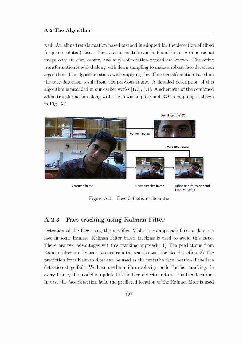
A.2 The Algorithm
well. An affine transformation based method is adopted for the detection of tilted
(in-plane rotated) faces. The rotation matrix can be found for an n dimensional
image once its size, center, and angle of rotation needed are known. The affine
transformation is added along with down sampling to make a robust face detection
algorithm. The algorithm starts with applying the affine transformation based on
the face detection result from the previous frame. A detailed description of this
algorithm is provided in our earlier works [173], [51]. A schematic of the combined
affine transformation along with the downsampling and ROI-remapping is shown
in Fig. A.1.
Figure A.1: Face detection schematic
A.2.3 Face tracking using Kalman Filter
Detection of the face using the modified Viola-Jones approach fails to detect a
face in some frames. Kalman Filter based tracking is used to avoid this issue.
There are two advantages wit this tracking approach, 1) The predictions from
Kalman filter can be used to constrain the search space for face detection, 2) The
prediction from Kalman filter can be used as the tentative face location if the face
detection stage fails. We have used a uniform velocity model for face tracking. In
every frame, the model is updated if the face detector returns the face location.
In case the face detection fails, the predicted location of the Kalman filter is used
127
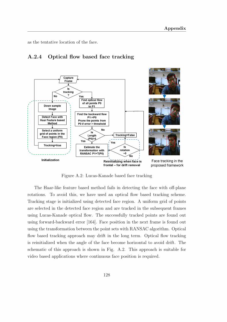
Appendix
as the tentative location of the face.
A.2.4 Optical flow based face tracking
Figure A.2: Lucas-Kanade based face tracking
The Haar-like feature based method fails in detecting the face with off-plane
rotations. To avoid this, we have used an optical flow based tracking scheme.
Tracking stage is initialized using detected face region. A uniform grid of points
are selected in the detected face region and are tracked in the subsequent frames
using Lucas-Kanade optical flow. The successfully tracked points are found out
using forward-backward error [164]. Face position in the next frame is found out
using the transformation between the point sets with RANSAC algorithm. Optical
flow based tracking approach may drift in the long term. Optical flow tracking
is reinitialized when the angle of the face become horizontal to avoid drift. The
schematic of this approach is shown in Fig. A.2. This approach is suitable for
video based applications where continuous face position is required.
128

References
[1] K. Ogaki, K. M. Kitani, Y. Sugano, and Y. Sato, “Coupling eye-motion and ego-motionfeatures for first-person activity recognition,” in Conference on Computer Vision and Pat-tern Recognition Workshops. IEEE, 2012, pp. 1–7.
[2] K. M. Kitani, T. Okabe, Y. Sato, and A. Sugimoto, “Fast unsupervised ego-action learn-ing for first-person sports videos,” in Computer Vision and Pattern Recognition, IEEEConference on, 2011, pp. 3241–3248.
[3] A. Oliva and A. Torralba, “Modeling the shape of the scene: A holistic representation ofthe spatial envelope,” International journal of computer vision, vol. 42, no. 3, pp. 145–175,2001.
[4] A. George and A. Routray, “Design and implementation of real-time algorithms for eyetracking and perclos measurement for on board estimation of alertness of drivers,” arXivpreprint arXiv:1505.06162, 2015.
[5] A. Duchowski, Eye tracking methodology: Theory and practice. Springer Science & Busi-ness Media, 2007, vol. 373.
[6] S. Happy, A. Dasgupta, A. George, and A. Routray, “A video database of human facesunder near infra-red illumination for human computer interaction applications,” in 20124th International Conference on Intelligent Human Computer Interaction (IHCI). IEEE,2012, pp. 1–4.
[7] L. R. Young and D. Sheena, “Survey of eye movement recording methods,” Behaviorresearch methods & instrumentation, vol. 7, no. 5, pp. 397–429, 1975.
[8] G. Westheimer, “Mechanism of saccadic eye movements,” AMA Archives of Ophthalmol-ogy, vol. 52, no. 5, pp. 710–724, 1954.
[9] C. H. Morimoto and M. R. Mimica, “Eye gaze tracking techniques for interactive applica-tions,” Computer Vision and Image Understanding, vol. 98, no. 1, pp. 4–24, 2005.
[10] X. Liu, F. Xu, and K. Fujimura, “Real-time eye detection and tracking for driver observa-tion under various light conditions,” in Intelligent Vehicle Symposium, IEEE, vol. 2, 2002,pp. 344–351.
[11] Z. Guang-yuan, C. Bo, J. Zhe, and L. Jia-wen, “A real-time eye detection system basedon the active ir illumination,” in Chinese Control and Decision Conference. IEEE, 2008,pp. 1255–1260.
[12] O. Ferhat and F. Vilarino, “Low cost eye tracking: The current panorama,” Computationalintelligence and neuroscience, 2016.
[13] A. Sengupta, A. Dasgupta, A. Chaudhuri, A. George, A. Routray, and R. Guha, “A mul-timodal system for assessing alertness levels due to cognitive loading,” IEEE Transactionson Neural Systems and Rehabilitation Engineering, vol. 25, no. 7, pp. 1037–1046, 2017.
[14] A. Sengupta, A. George, A. Dasgupta, A. Chaudhuri, B. Kabi, and A. Routray, “Alertnessmonitoring system for vehicle drivers using physiological signals,” in Handbook of Researchon Emerging Innovations in Rail Transportation Engineering. IGI Global, 2016, pp. 273–311.
129
[15] A. Dasgupta, B. Kabi, A. George, S. Happy, and A. Routray, “A drowsiness detectionscheme based on fusion of voice and vision cues,” arXiv preprint arXiv:1509.04887, 2015.
[16] P. Kasprowski and J. Ober, “Eye movements in biometrics,” in International Workshopon Biometric Authentication. Springer, 2004, pp. 248–258.
[17] Y. S. Pai, B. Tag, B. Outram, N. Vontin, K. Sugiura, and K. Kunze, “Gazesim: simulatingfoveated rendering using depth in eye gaze for vr,” in ACM SIGGRAPH Posters, 2016,p. 75.
[18] A. T. Duchowski, N. Cournia, and H. Murphy, “Gaze-contingent displays: A review,”CyberPsychology & Behavior, vol. 7, no. 6, pp. 621–634, 2004.
[19] A. T. Duchowski, “A breadth-first survey of eye-tracking applications,” Behavior ResearchMethods, Instruments, & Computers, vol. 34, no. 4, pp. 455–470, 2002.
[20] R. Jacob and K. S. Karn, “Eye tracking in human-computer interaction and usabilityresearch: Ready to deliver the promises,” Mind, vol. 2, no. 3, p. 4, 2003.
[21] S. Zhai, C. Morimoto, and S. Ihde, “Manual and gaze input cascaded (magic) pointing,”pp. 246–253, 1999.
[22] A. Patney, J. Kim, M. Salvi, A. Kaplanyan, C. Wyman, N. Benty, A. Lefohn, and D. Lue-bke, “Perceptually-based foveated virtual reality,” in ACM SIGGRAPH Emerging Tech-nologies, 2016, p. 17.
[23] P. Majaranta and A. Bulling, “Eye tracking and eye-based human–computer interaction,”in Advances in physiological computing. Springer, 2014, pp. 39–65.
[24] P. Majaranta and K.-J. Raiha, “Twenty years of eye typing: systems and design issues,”in Symposium on Eye tracking research & applications. ACM, 2002, pp. 15–22.
[25] A. Ueno, T. Tateyama, M. Takase, and H. Minamitani, “Dynamics of saccadic eye move-ment depending on diurnal variation in human alertness,” Systems and Computers inJapan, vol. 33, no. 7, pp. 95–103, 2002.
[26] G. Diamantopoulos, S. I. Woolley, and M. Spann, “A critical review of past research intothe neuro-linguistic programming eye-accessing cues model,” Current Research in NLP,p. 8, 2009.
[27] R. J. Leigh and D. S. Zee, The neurology of eye movements. Oxford University Press,USA, 2015, vol. 90.
[28] D. L. Levy, A. B. Sereno, D. C. Gooding, and G. A. ODriscoll, “Eye tracking dysfunctionin schizophrenia: characterization and pathophysiology,” in Behavioral Neurobiology ofSchizophrenia and Its Treatment. Springer, 2010, pp. 311–347.
[29] P. Majaranta, Gaze Interaction and Applications of Eye Tracking: Advances in AssistiveTechnologies: Advances in Assistive Technologies. IGI Global, 2011.
[30] D. W. Hansen and Q. Ji, “In the eye of the beholder: A survey of models for eyes andgaze,” Pattern Analysis and Machine Intelligence, IEEE Transactions on, vol. 32, no. 3,pp. 478–500, 2010.
[31] X. Zhang, Y. Sugano, M. Fritz, and A. Bulling, “Appearance-based gaze estimation in thewild,” in Proceedings of the IEEE Conference on Computer Vision and Pattern Recogni-tion, 2015, pp. 4511–4520.
130
[32] J. Illingworth and J. Kittler, “A survey of the hough transform,” Computer vision, graph-ics, and image processing, vol. 44, no. 1, pp. 87–116, 1988.
[33] D. Young, H. Tunley, and R. Samuels, Specialised hough transform and active contourmethods for real-time eye tracking. University of Sussex, Cognitive & Computing Science,1995.
[34] M. Smereka and I. Duleba, “Circular object detection using a modified hough transform,”International Journal of Applied Mathematics and Computer Science, vol. 18, no. 1, pp.85–91, 2008.
[35] T. J. Atherton and D. J. Kerbyson, “Size invariant circle detection,” Image and Visioncomputing, vol. 17, no. 11, pp. 795–803, 1999.
[36] P. Yang, B. Du, S. Shan, and W. Gao, “A novel pupil localization method based on gabor-eye model and radial symmetry operator,” in Image Processing, International Conferenceon, vol. 1. IEEE, 2004, pp. 67–70.
[37] R. Valenti and T. Gevers, “Accurate eye center location through invariant isocentric pat-terns,” Pattern Analysis and Machine Intelligence, IEEE Transactions on, vol. 34, no. 9,pp. 1785–1798, 2012.
[38] R. Valenti, N. Sebe, and T. Gevers, “Combining head pose and eye location informationfor gaze estimation,” Image Processing, IEEE Transactions on, vol. 21, no. 2, pp. 802–815,2012.
[39] F. Timm and E. Barth, “Accurate eye centre localisation by means of gradients.” VISAPP,vol. 11, pp. 125–130, 2011.
[40] T. D’Orazio, N. Ancona, G. Cicirelli, and M. Nitti, “A ball detection algorithm for realsoccer image sequences,” in Pattern Recognition, 16th International Conference on, vol. 1.IEEE, 2002, pp. 210–213.
[41] J. Daugman, “How iris recognition works,” Circuits and Systems for Video Technology,IEEE Transactions on, vol. 14, no. 1, pp. 21–30, 2004.
[42] S.-J. Baek, K.-A. Choi, C. Ma, Y.-H. Kim, and S.-J. Ko, “Eyeball model-based iris centerlocalization for visible image-based eye-gaze tracking systems,” Consumer Electronics,IEEE Transactions on, vol. 59, no. 2, pp. 415–421, 2013.
[43] W. Sewell and O. Komogortsev, “Real-time eye gaze tracking with an unmodified com-modity webcam employing a neural network,” in CHI’10 Extended Abstracts on HumanFactors in Computing Systems. ACM, 2010, pp. 3739–3744.
[44] Z.-H. Zhou and X. Geng, “Projection functions for eye detection,” Pattern recognition,vol. 37, no. 5, pp. 1049–1056, 2004.
[45] T. Bhaskar, F. T. Keat, S. Ranganath, and Y. Venkatesh, “Blink detection and eye track-ing for eye localization,” in Conference on Convergent Technologies for the Asia-PacificRegion, vol. 2. IEEE, 2003, pp. 821–824.
[46] J. Wang, E. Sung, and R. Venkateswarlu, “Eye gaze estimation from a single image of oneeye,” in Computer Vision, Ninth IEEE International Conference on, 2003, pp. 136–143.
[47] N. Markus, M. Frljak, I. S. Pandzic, J. Ahlberg, and R. Forchheimer, “Eye pupil local-ization with an ensemble of randomized trees,” Pattern recognition, vol. 47, no. 2, pp.578–587, 2014.
131
[48] T. Schneider, B. Schauerte, and R. Stiefelhagen, “Manifold alignment for person inde-pendent appearance-based gaze estimation,” in 22nd International Conference on PatternRecognition. IEEE, 2014, pp. 1167–1172.
[49] Y. Sugano, Y. Matsushita, and Y. Sato, “Learning-by-synthesis for appearance-based 3dgaze estimation,” in Proceedings of the IEEE Conference on Computer Vision and PatternRecognition, 2014, pp. 1821–1828.
[50] P. Viola and M. Jones, “Rapid object detection using a boosted cascade of simple features,”in Computer Vision and Pattern Recognition. Proceedings of the IEEE Computer SocietyConference on, vol. 1, 2001, pp. I–511.
[51] A. Dasgupta, A. George, S. Happy, and A. Routray, “A vision-based system for monitoringthe loss of attention in automotive drivers,” IEEE Transactions on Intelligent Transporta-tion Systems, vol. 14, no. 4, pp. 1825–1838, 2013.
[52] D. Li, D. Winfield, and D. J. Parkhurst, “Starburst: A hybrid algorithm for video-basedeye tracking combining feature-based and model-based approaches,” in Computer Visionand Pattern Recognition-Workshops, IEEE Computer Society Conference on, 2005, pp.79–79.
[53] A. Fitzgibbon, M. Pilu, and R. B. Fisher, “Direct least square fitting of ellipses,” PatternAnalysis and Machine Intelligence, IEEE Transactions on, vol. 21, no. 5, pp. 476–480,1999.
[54] M. A. Fischler and R. C. Bolles, “Random sample consensus: a paradigm for model fittingwith applications to image analysis and automated cartography,” Communications of theACM, vol. 24, no. 6, pp. 381–395, 1981.
[55] L. Swirski, A. Bulling, and N. Dodgson, “Robust real-time pupil tracking in highly off-axis images,” in Proceedings of the Symposium on Eye Tracking Research and Applications.ACM, 2012, pp. 173–176.
[56] Y. Yoon, A. Kosaka, and A. C. Kak, “A new kalman-filter-based framework for fast andaccurate visual tracking of rigid objects,” Robotics, IEEE Transactions on, vol. 24, no. 5,pp. 1238–1251, 2008.
[57] A. Kiruluta, M. Eizenman, and S. Pasupathy, “Predictive head movement tracking usinga kalman filter,” Systems, Man, and Cybernetics, Part B: Cybernetics, IEEE Transactionson, vol. 27, no. 2, pp. 326–331, 1997.
[58] N. Dalal and B. Triggs, “Histograms of oriented gradients for human detection,” in Com-puter Vision and Pattern Recognition, IEEE Computer Society Conference on, vol. 1, 2005,pp. 886–893.
[59] D. Cristinacce and T. F. Cootes, “Facial feature detection and tracking with automatictemplate selection,” in Automatic Face and Gesture Recognition, 7th International Con-ference on. IEEE, 2006, pp. 429–434.
[60] D. Vukadinovic and M. Pantic, “Fully automatic facial feature point detection using gaborfeature based boosted classifiers,” in Systems, Man and Cybernetics, IEEE InternationalConference on, vol. 2, 2005, pp. 1692–1698.
[61] J. Lewis, “Fast normalized cross-correlation,” in Vision interface, vol. 10, no. 1, 1995, pp.120–123.
132

[62] C. Tomasi and T. Kanade, Detection and tracking of point features. School of ComputerScience, Carnegie Mellon Univ. Pittsburgh, 1991.
[63] B. Pires, M. Hwangbo, M. Devyver, and T. Kanade, “Visible-spectrum gaze trackingfor sports,” in Proceedings of the IEEE Conference on Computer Vision and PatternRecognition Workshops, 2013, pp. 1005–1010.
[64] J. Sigut and S.-A. Sidha, “Iris center corneal reflection method for gaze tracking usingvisible light,” Biomedical Engineering, IEEE Transactions on, vol. 58, no. 2, pp. 411–419,2011.
[65] E. A. Nadaraya, “On estimating regression,” Theory of Probability & Its Applications,vol. 9, no. 1, pp. 141–142, 1964.
[66] R. Kohn, M. Smith, and D. Chan, “Nonparametric regression using linear combinationsof basis functions,” Statistics and Computing, vol. 11, no. 4, pp. 313–322, 2001.
[67] T. F. Cootes, G. J. Edwards, and C. J. Taylor, “Active appearance models,” IEEE Trans-actions on Pattern Analysis & Machine Intelligence, vol. 23, no. 6, pp. 681–685, 2001.
[68] D. Cristinacce and T. F. Cootes, “Feature detection and tracking with constrained localmodels.” in Proceedings of the British Machine Vision Conference, vol. 2, no. 5, 2006, p. 6.
[69] P. Viola and M. J. Jones, “Robust real-time face detection,” International journal ofcomputer vision, vol. 57, no. 2, pp. 137–154, 2004.
[70] O. Jesorsky, K. J. Kirchberg, and R. W. Frischholz, “Robust face detection using thehausdorff distance,” in Audio-and video-based biometric person authentication. Springer,2001, pp. 90–95.
[71] “Bioid database,” https://www.bioid.com/About/BioID-Face-Database/, accessed: 2015-04-09.
[72] V. Ponz, A. Villanueva, and R. Cabeza, “Dataset for the evaluation of eye detector forgaze estimation,” in Proceedings of the ACM Conference on Ubiquitous Computing, 2012,pp. 681–684.
[73] C. Burrus and T. W. Parks, DFT/FFT and Convolution Algorithms: theory and Imple-mentation. John Wiley & Sons, Inc., 1991.
[74] G. Bradski et al., “The opencv library,” Doctor Dobbs Journal, vol. 25, no. 11, pp. 120–126,2000.
[75] A. George and A. Routray, “Escaf: Pupil centre localization algorithm with candidatefiltering,” arXiv preprint arXiv:1807.10520, 2018.
[76] T. Starner, “Project glass: An extension of the self,” Pervasive Computing, IEEE, vol. 12,no. 2, pp. 14–16, 2013.
[77] H. Benko, E. Ofek, F. Zheng, and A. D. Wilson, “Fovear: Combining an optically see-through near-eye display with projector-based spatial augmented reality,” in Proceedingsof the 28th Annual ACM Symposium on User Interface Software & Technology. ACM,2015, pp. 129–135.
[78] B. Guenter, M. Finch, S. Drucker, D. Tan, and J. Snyder, “Foveated 3d graphics,” ACMTransactions on Graphics, vol. 31, no. 6, p. 164, 2012.
133

[79] J. San Agustin, H. Skovsgaard, E. Mollenbach, M. Barret, M. Tall, D. W. Hansen, andJ. P. Hansen, “Evaluation of a low-cost open-source gaze tracker,” in Symposium on Eye-Tracking Research & Applications. ACM, 2010, pp. 77–80.
[80] M. Kassner, W. Patera, and A. Bulling, “Pupil: an open source platform for pervasive eyetracking and mobile gaze-based interaction,” in Proceedings of the 2014 ACM InternationalJoint Conference on Pervasive and Ubiquitous Computing: Adjunct Publication. ACM,2014, pp. 1151–1160.
[81] A.-H. Javadi, Z. Hakimi, M. Barati, V. Walsh, and L. Tcheang, “Set: a pupil detectionmethod using sinusoidal approximation,” Frontiers in neuroengineering, vol. 8, 2015.
[82] W. Fuhl, T. Kubler, K. Sippel, W. Rosenstiel, and E. Kasneci, “Excuse: Robust pupildetection in real-world scenarios,” in Computer analysis of images and patterns. Springer,2015, pp. 39–51.
[83] W. Fuhl, T. C. Santini, T. Kuebler, and E. Kasneci, “Else: Ellipse selection for robustpupil detection in real-world environments,” pp. 123–130, 2016.
[84] S. Suzuki et al., “Topological structural analysis of digitized binary images by borderfollowing,” Computer Vision, Graphics, and Image Processing, vol. 30, no. 1, pp. 32–46,1985.
[85] D. H. Douglas and T. K. Peucker, “Algorithms for the reduction of the number of pointsrequired to represent a digitized line or its caricature,” Cartographica: The InternationalJournal for Geographic Information and Geovisualization, vol. 10, no. 2, pp. 112–122, 1973.
[86] A. Fitzgibbon and R. B. Fisher, “A buyer’s guide to conic fitting,” in British MachineVision Conference, 1995, pp. 513–522.
[87] J. Matas, O. Chum, M. Urban, and T. Pajdla, “Robust wide-baseline stereo from maxi-mally stable extremal regions,” Image and vision computing, vol. 22, no. 10, pp. 761–767,2004.
[88] D. Nister and H. Stewenius, “Linear time maximally stable extremal regions,” in EuropeanConference on Computer Vision. Springer, 2008, pp. 183–196.
[89] P.-E. Forssen and D. G. Lowe, “Shape descriptors for maximally stable extremal regions,”in 11th International Conference on Computer Vision. IEEE, 2007, pp. 1–8.
[90] M. Tonsen, X. Zhang, Y. Sugano, and A. Bulling, “Labelled pupils in the wild: a datasetfor studying pupil detection in unconstrained environments,” in Proceedings of the NinthBiennial ACM Symposium on Eye Tracking Research & Applications. ACM, 2016, pp.139–142.
[91] W. Fuhl, M. Tonsen, A. Bulling, and E. Kasneci, “Pupil detection in the wild: An evalu-ation of the state of the art in mobile head-mounted eye tracking,” Machine Vision andApplications, 2016.
[92] L. L. Di Stasi, R. Renner, A. Catena, J. J. Canas, B. M. Velichkovsky, and S. Pannasch,“Towards a driver fatigue test based on the saccadic main sequence: A partial validationby subjective report data,” Transportation research part C: emerging technologies, vol. 21,no. 1, pp. 122–133, 2012.
134
[93] Y. Terao, H. Fukuda, A. Yugeta, O. Hikosaka, Y. Nomura, M. Segawa, R. Hanajima,S. Tsuji, and Y. Ugawa, “Initiation and inhibitory control of saccades with the progressionof parkinson’s disease–changes in three major drives converging on the superior colliculus,”Neuropsychologia, vol. 49, no. 7, pp. 1794–1806, 2011.
[94] R. Bandler and J. Grinder, “Frogs into princes: Neuro linguistic programming,” 2012.
[95] J. Sturt, S. Ali, W. Robertson, D. Metcalfe, A. Grove, C. Bourne, and C. Bridle, “Neu-rolinguistic programming: a systematic review of the effects on health outcomes,” BritishJournal of General Practice, vol. 62, no. 604, pp. e757–e764, 2012.
[96] R. Vranceanu, L. Florea, and C. Florea, “A computer vision approach for the eye accesingcue model used in neuro-linguistic programming,” Sci. Bull. Univ. Politehnica BucharestSer. C, vol. 75, no. 4, pp. 79–90, 2013.
[97] R. Vranceanu, C. Vertan, R. Condorovici, L. Florea, and C. Florea, “A fast method for de-tecting eye accessing cues used in neuro-linguistic programming,” in Intelligent ComputerCommunication and Processing, IEEE International Conference on, 2011, pp. 225–229.
[98] R. Vranceanu, C. Florea, L. Florea, and C. Vertan, “Automatic detection of gaze direc-tion for nlp applications,” in Signals, Circuits and Systems, International Symposium on.IEEE, 2013, pp. 1–4.
[99] K. Radlak, M. Kawulok, B. Smolka, and N. Radlak, “Gaze direction estimation from staticimages,” in Multimedia Signal Processing, 16th International Workshop on. IEEE, 2014,pp. 1–4.
[100] F. Song, X. Tan, S. Chen, and Z.-H. Zhou, “A literature survey on robust and efficienteye localization in real-life scenarios,” Pattern Recognition, vol. 46, no. 12, pp. 3157–3173,2013.
[101] R. Vranceanu, C. Florea, L. Florea, and C. Vertan, “Gaze direction estimation by compo-nent separation for recognition of eye accessing cues,” Machine Vision and Applications,vol. 26, no. 2-3, pp. 267–278, 2015.
[102] S. Asteriadis, D. Soufleros, K. Karpouzis, and S. Kollias, “A natural head pose and eyegaze dataset,” in Proceedings of the International Workshop on Affective-Aware VirtualAgents and Social Robots. ACM, 2009, p. 1.
[103] V. Kazemi and J. Sullivan, “One millisecond face alignment with an ensemble of regressiontrees,” in Computer Vision and Pattern Recognition, IEEE Conference on, 2014, pp. 1867–1874.
[104] A. Krizhevsky, I. Sutskever, and G. E. Hinton, “Imagenet classification with deep convolu-tional neural networks,” in Advances in neural information processing systems, 2012, pp.1097–1105.
[105] Y. LeCun, L. Bottou, Y. Bengio, and P. Haffner, “Gradient-based learning applied todocument recognition,” Proceedings of the IEEE, vol. 86, no. 11, pp. 2278–2324, 1998.
[106] L. Bottou, “Large-scale machine learning with stochastic gradient descent,” in Proceedingsof COMPSTAT. Springer, 2010, pp. 177–186.
[107] L. Florea, C. Florea, R. Vranceanu, and C. Vertan, “Can your eyes tell me how you think?a gaze directed estimation of the mental activity,” in Proceedings of the British MachineVision Conference, 2013, pp. 60–1.
135
[108] R. Vranceanu, C. Florea, L. Florea, and C. Vertan, “Nlp eac recognition by componentseparation in the eye region,” in Computer Analysis of Images and Patterns. Springer,2013, pp. 225–232.
[109] M. Valstar, B. Martinez, X. Binefa, and M. Pantic, “Facial point detection using boostedregression and graph models,” in Computer Vision and Pattern Recognition, IEEE Con-ference on, 2010, pp. 2729–2736.
[110] R. Valenti and T. Gevers, “Accurate eye center location and tracking using isophote cur-vature,” in Computer Vision and Pattern Recognition, IEEE Conference on, 2008, pp.1–8.
[111] X. Zhu and D. Ramanan, “Face detection, pose estimation, and landmark localization inthe wild,” in Computer Vision and Pattern Recognition, IEEE Conference on, 2012, pp.2879–2886.
[112] A. K. Jain, P. Flynn, and A. A. Ross, Handbook of biometrics. Springer Science &Business Media, 2007.
[113] A. K. Jain, A. Ross, and S. Prabhakar, “An introduction to biometric recognition,” Circuitsand Systems for Video Technology, IEEE Transactions on, vol. 14, no. 1, pp. 4–20, 2004.
[114] L. Wang, X. Geng, L. Wang, and X. Geng, Behavioral Biometrics For Human Identifica-tion: Intelligent Applications. IGI Global, 2009.
[115] S. Marcel and J. d. R. Millan, “Person authentication using brainwaves (eeg) and max-imum a posteriori model adaptation,” Pattern Analysis and Machine Intelligence, IEEETransactions on, vol. 29, no. 4, pp. 743–752, 2007.
[116] K. N. Plataniotis, D. Hatzinakos, and J. K. Lee, “Ecg biometric recognition withoutfiducial detection,” in Biometric Consortium Conference. IEEE, 2006, pp. 1–6.
[117] I.B. Group, “Independent testing of iris recognition technology,” Final Report,NBCHC030114/0002, 2005.
[118] C. Roberts, “Biometric attack vectors and defences,” Computers & Security, vol. 26, no. 1,pp. 14–25, 2007.
[119] S. Schuckers, L. Hornak, T. Norman, R. Derakhshani, and S. Parthasaradhi, “Issues forliveness detection in biometrics,” in Proceedings of Biometric Consortium Conference.IEEE, 2002.
[120] R. J. Leigh and D. S. Zee, The neurology of eye movements. Oxford university press NewYork, 1999, vol. 90.
[121] T. Kinnunen, F. Sedlak, and R. Bednarik, “Towards task-independent person authentica-tion using eye movement signals,” in Symposium on Eye-Tracking Research & Applications.ACM, 2010, pp. 187–190.
[122] R. Bednarik, T. Kinnunen, A. Mihaila, and P. Franti, “Eye-movements as a biometric,”in Image analysis. Springer, 2005, pp. 780–789.
[123] O. V. Komogortsev, S. Jayarathna, C. R. Aragon, and M. Mahmoud, “Biometric iden-tification via an oculomotor plant mathematical model,” in Symposium on Eye-TrackingResearch & Applications. ACM, 2010, pp. 57–60.
136
[124] O. V. Komogortsev, A. Karpov, L. R. Price, and C. Aragon, “Biometric authenticationvia oculomotor plant characteristics,” in Biometrics, 5th IAPR International Conferenceon. IEEE, 2012, pp. 413–420.
[125] C. D. Holland and O. V. Komogortsev, “Complex eye movement pattern biometrics: theeffects of environment and stimulus,” Information Forensics and Security, IEEE Transac-tions on, vol. 8, no. 12, pp. 2115–2126, 2013.
[126] I. Rigas, G. Economou, and S. Fotopoulos, “Biometric identification based on the eyemovements and graph matching techniques,” Pattern Recognition Letters, vol. 33, no. 6,pp. 786–792, 2012.
[127] I. Rigas, G. Economou, and S. Fotopoulos, “Human eye movements as a trait for biomet-rical identification,” in Biometrics: Theory, Applications and Systems, Fifth InternationalConference on. IEEE, 2012, pp. 217–222.
[128] Y. Zhang and M. Juhola, “On biometric verification of a user by means of eye movementdata mining,” in The Second International Conference on Advances in Information Miningand Management, 2012, pp. 85–90.
[129] V. Cantoni, C. Galdi, M. Nappi, M. Porta, and D. Riccio, “Gant: Gaze analysis techniquefor human identification,” Pattern Recognition, vol. 48, no. 4, pp. 1027–1038, 2015.
[130] C. Holland and O. V. Komogortsev, “Biometric identification via eye movement scanpathsin reading,” in Biometrics, International Joint Conference on. IEEE, 2011, pp. 1–8.
[131] C. D. Holland and O. V. Komogortsev, “Complex eye movement pattern biometrics: An-alyzing fixations and saccades,” in Biometrics, International Conference on. IEEE, 2013,pp. 1–8.
[132] “Bioeye2015,competition on biometrics via eye movements,” http://bioeye.cs.txstate.edu/,accessed: 2015-04-09.
[133] H. Collewijn, C. J. Erkelens, and R. Steinman, “Binocular co-ordination of human hori-zontal saccadic eye movements.” The Journal of Physiology, vol. 404, no. 1, pp. 157–182,1988.
[134] C. M. Harris, I. Abramov, and L. Hainl, “Instrument considerations in measuring fast eyemovements,” Behavior Research Methods, Instruments, & Computers, vol. 16, no. 4, pp.341–350, 1984.
[135] S. R. Krishnan and C. S. Seelamantula, “On the selection of optimum savitzky-golayfilters,” Signal Processing, IEEE Transactions on, vol. 61, no. 2, pp. 380–391, 2013.
[136] A. Savitzky and M. J. Golay, “Smoothing and differentiation of data by simplified leastsquares procedures.” Analytical chemistry, vol. 36, no. 8, pp. 1627–1639, 1964.
[137] C. D. Holland and O. V. Komogortsev, “Biometric verification via complex eye move-ments: The effects of environment and stimulus,” in Biometrics: Theory, Applicationsand Systems, Fifth International Conference on. IEEE, 2012, pp. 39–46.
[138] D. D. Salvucci and J. H. Goldberg, “Identifying fixations and saccades in eye-trackingprotocols,” in Symposium on Eye tracking research & applications. ACM, 2000, pp.71–78.
[139] M. R. Harwood and J. P. Herman, “Optimally straight and optimally curved saccades,”The Journal of Neuroscience, vol. 28, no. 30, pp. 7455–7457, 2008.
137

[140] R. Kohavi and G. H. John, “Wrappers for feature subset selection,” Artificial intelligence,vol. 97, no. 1, pp. 273–324, 1997.
[141] H. H. Goossens and A. Van Opstal, “Human eye-head coordination in two dimensionsunder different sensorimotor conditions,” Experimental Brain Research, vol. 114, no. 3,pp. 542–560, 1997.
[142] D. S. Broomhead and D. Lowe, “Radial basis functions, multi-variable functional interpo-lation and adaptive networks,” DTIC Document, Tech. Rep., 1988.
[143] F. Schwenker, H. A. Kestler, and G. Palm, “Three learning phases for radial-basis-functionnetworks,” Neural networks, vol. 14, no. 4, pp. 439–458, 2001.
[144] D. Maio, D. Maltoni, R. Cappelli, J. L. Wayman, and A. K. Jain, “Fvc2004: Thirdfingerprint verification competition,” in Biometric Authentication. Springer, 2004, pp.1–7.
[145] P. J. Phillips, W. T. Scruggs, A. J. O’Toole, P. J. Flynn, K. W. Bowyer, C. L. Schott, andM. Sharpe, “Frvt 2006 and ice 2006 large-scale experimental results,” Pattern Analysisand Machine Intelligence, IEEE Transactions on, vol. 32, no. 5, pp. 831–846, 2010.
[146] O. V. Komogortsev, C. D. Holland, and A. Karpov, “Template aging in eye movement-driven biometrics,” in SPIE Defense+ Security. International Society for Optics andPhotonics, 2014, pp. 90 750A–90 750A.
[147] P. Kasprowski, “The impact of temporal proximity between samples on eye movementbiometric identification,” in Computer Information Systems and Industrial Management.Springer, 2013, pp. 77–87.
[148] A. George and A. Routray, “Recognition of activities from eye gaze and egocentric video,”arXiv preprint arXiv:1805.07253, 2018.
[149] R. Poppe, “A survey on vision-based human action recognition,” Image and vision com-puting, vol. 28, no. 6, pp. 976–990, 2010.
[150] D. Weinland, R. Ronfard, and E. Boyer, “A survey of vision-based methods for action rep-resentation, segmentation and recognition,” Computer Vision and Image Understanding,vol. 115, no. 2, pp. 224–241, 2011.
[151] P. Turaga, R. Chellappa, V. S. Subrahmanian, and O. Udrea, “Machine recognition of hu-man activities: A survey,” Circuits and Systems for Video Technology, IEEE Transactionson, vol. 18, no. 11, pp. 1473–1488, 2008.
[152] A. Fathi, A. Farhadi, and J. M. Rehg, “Understanding egocentric activities,” in ComputerVision, IEEE International Conference on, 2011, pp. 407–414.
[153] H. Pirsiavash and D. Ramanan, “Detecting activities of daily living in first-person cameraviews,” in Computer Vision and Pattern Recognition, IEEE Conference on, 2012, pp.2847–2854.
[154] Y. Yan, E. Ricci, G. Liu, and N. Sebe, “Egocentric daily activity recognition via multitaskclustering,” Image Processing, IEEE Transactions on, vol. 24, no. 10, pp. 2984–2995, 2015.
[155] T.-H.-C. Nguyen, J.-C. Nebel, and F. Florez-Revuelta, “Recognition of activities of dailyliving with egocentric vision: A review.” Sensors (Basel, Switzerland), vol. 16, no. 72,2016.
138
[156] A. Bulling, J. A. Ward, H. Gellersen, and G. Troster, “Eye movement analysis for activityrecognition using electrooculography,” IEEE transactions on pattern analysis and machineintelligence, vol. 33, no. 4, pp. 741–753, 2011.
[157] I. M. Hipiny and W. Mayol-Cuevas, “Recognising egocentric activities from gaze regionswith multiple-voting bag of words,” University of Bristol, Tech. Rep., 2012.
[158] Y. Li, Z. Ye, and J. M. Rehg, “Delving into egocentric actions,” in Proceedings of theIEEE Conference on Computer Vision and Pattern Recognition, 2015, pp. 287–295.
[159] A. Fathi, Y. Li, and J. M. Rehg, “Learning to recognize daily actions using gaze,” inEuropean Conference on Computer Vision. Springer, 2012, pp. 314–327.
[160] Y. Shiga, T. Toyama, Y. Utsumi, K. Kise, and A. Dengel, “Daily activity recognitioncombining gaze motion and visual features,” in Proceedings of the International JointConference on Pervasive and Ubiquitous Computing: Adjunct Publication. ACM, 2014,pp. 1103–1111.
[161] K. Kunze, M. Iwamura, K. Kise, S. Uchida, and S. Omachi, “Activity recognition for themind: Toward a cognitive” quantified self”,” Computer, vol. 46, no. 10, pp. 105–108, 2013.
[162] A. Sharif Razavian, H. Azizpour, J. Sullivan, and S. Carlsson, “Cnn features off-the-shelf: an astounding baseline for recognition,” in Proceedings of the IEEE Conference onComputer Vision and Pattern Recognition Workshops, 2014, pp. 806–813.
[163] Y. Gong, L. Wang, R. Guo, and S. Lazebnik, “Multi-scale orderless pooling of deep con-volutional activation features,” in European Conference on Computer Vision. Springer,2014, pp. 392–407.
[164] Z. Kalal, K. Mikolajczyk, and J. Matas, “Forward-backward error: Automatic detectionof tracking failures,” in Pattern recognition, IEEE 20th international conference on, 2010,pp. 2756–2759.
[165] A. A. Ross and R. Govindarajan, “Feature level fusion of hand and face biometrics,” inDefense and Security. International Society for Optics and Photonics, 2005, pp. 196–204.
[166] L. Breiman, “Random forests,” Machine learning, vol. 45, no. 1, pp. 5–32, 2001.
[167] Y. Ma, B. Cukic, and H. Singh, “A classification approach to multi-biometric score fusion,”in International Conference on Audio-and Video-Based Biometric Person Authentication.Springer, 2005, pp. 484–493.
[168] E. H. Spriggs, F. De La Torre, and M. Hebert, “Temporal segmentation and activity clas-sification from first-person sensing,” in IEEE Computer Society Conference on ComputerVision and Pattern Recognition Workshops, 2009, pp. 17–24.
[169] P. Jones, P. Viola, and M. Jones, “Rapid object detection using a boosted cascade ofsimple features,” in University of Rochester. Charles Rich, 2001.
[170] R. Lienhart and J. Maydt, “An extended set of haar-like features for rapid object detec-tion,” in Image Processing, International Conference on, vol. 1, 2002, pp. I–900.
[171] A. George, A. Dasgupta, and A. Routray, “A framework for fast face and eye detection,”arXiv preprint arXiv:1505.03344, 2015.
[172] A. Dasgupta, A. Mandloi, A. George, and A. Routray, “An improved algorithm for eyecorner detection,” in 2016 International Conference on Signal Processing and Communi-cations (SPCOM). IEEE, 2016, pp. 1–4.
139

[173] A. Dasgupta, A. George, S. Happy, A. Routray, and T. Shanker, “An on-board visionbased system for drowsiness detection in automotive drivers,” International Journal ofAdvances in Engineering Sciences and Applied Mathematics, vol. 5, no. 2-3, pp. 94–103,2013.
140
Publications from this Thesis
Journals
1. A. George, A. Routray, “Fast and Accurate Eye Localisation Algorithmfor Gaze Tracking in Low Resolution Images”, IET Computer Vision, vol.10, no. 7, pp.660-669, 2016.
2. A. George, A. Routray, “A score level fusion method for eye movement bio-metrics”, Pattern Recognition Letters, vol. 82, no. 2, pp. 207-215, Elsevier,2015.
3. A. Sengupta, A. Dasgupta, A. Chaudhuri, A. George, A. Routray, R.Guha,“A Multimodal System for Assessing Alertness Levels due to Cogni-tive Loading”, in IEEE in Transactions on Neural Systems & RehabilitationEngineering, 2017.
Book Chapters
1. A. Sengupta, A. George, A. Dasgupta, A. Chaudhuri, B. Kabi, A. Routray ,“Alertness monitoring system for vehicle drivers using physiological signals”.Handbook of Research on Emerging Innovations in Rail Transportation En-gineering, pp. 273-311, IGI Global, 2016.
Conferences
1. A. George, A. Routray, “Real-time Eye Gaze Direction Classification Us-ing Convolutional Neural Network”, SPCOM, International Conference onSignal Processing and Communications, IEEE, pp. 1-5, 2016.
2. A. Dasgupta, A. Mandloi, A. George, A. Routray, “An Improved Algorithmfor Eye Corner Detection”, SPCOM, International Conference on SignalProcessing and Communications, IEEE , pp. 1-4, 2016.
3. G. Banik, P. Patnaik, A. George, A. Routray, “Contextual Priming andPerception Manipulation: An Exploration through Eye-Tracking and Audi-ence Response”, NAOP Convention 2016, Allahabad.
141


Curriculum Vita
Contact Information
Name: Anjith GeorgePermanent Address: Thannikkapara House, Kolikkadavu,
Payam P.O, Kannur DT, KeralaPIN–670704, India.
Email: [email protected]: +91-7501-549613
Research Interests
Human Computer Interaction, Gaze Tracking and applications, Biometrics, Com-puter Vision, Pattern Recognition and Machine Learning.
Education
2012-2017 Ph.DImage based eye gaze tracking and its applicationsIndian Institute of Technology Kharagpur, India
2010-2012 M.TechInstrumentation EngineeringIndian Institute of Technology Kharagpur, India
2006-2010 B.TechElectrical and Electronics EngineeringUniversity of Calicut, Kerala, India
Awards & Honours
• Winner, BioEye 2015, International Eye Movement based biometrics com-petition, Organized by IEEE BTAS.
• Finalist: Intel India Embedded Challenge 2012.
• Secured 99.2 and 98.1 percentile in Electrical engineering GATE 2010and GATE 2012.
• MHRD Fellowship during M Tech and PhD

Publications
• A. George, A. Routray, “Fast and Accurate Eye Localisation Algorithm forGaze Tracking in Low Resolution Images”, IET Computer Vision, vol. 10, no. 7,pp.660-669, 2016.
• A. George, A. Routray, “A score level fusion method for eye movement biomet-rics”, Pattern Recognition Letters, vol. 82, no. 2, pp. 207-215, Elsevier, 2015.
• A. Dasgupta, A. George, S. L. Happy, A. Routray, “A Vision Based System forMonitoring the Loss of Attention in Automotive Drivers”, in IEEE Transactionson Intelligent Transportation Systems, vol. 14, no. 4, pp.1825-1838, 2013
• A. Dasgupta, A. George, S. L. Happy, A. Routray, Tara Shanker, “An on-boardvision based system for drowsiness detection in automotive drivers”, in Interna-tional Journal of Advances in Engineering Sciences and Applied Mathematics,Springer, vol. 5, no. 2-3, pp. 94-103, 2013.
• A. Sengupta, A. Dasgupta, A. Chaudhuri, A. George, A. Routray, R. Guha,“AMultimodal System for Assessing Alertness Levels due to Cognitive Loading”, inIEEE in Transactions on Neural Systems & Rehabilitation Engineering, 2017.
• A. Sengupta, A. George, A. Dasgupta, A. Chaudhuri, B. Kabi, A. Routray, “Alertness monitoring system for vehicle drivers using physiological signals”.Handbook of Research on Emerging Innovations in Rail Transportation Engineer-ing, pp. 273-311, IGI Global, 2016.
• A. George, A. Routray, “Real-time Eye Gaze Direction Classification Using Con-volutional Neural Network”, SPCOM, International Conference on Signal Pro-cessing and Communications, IEEE, pp. 1-5, 2016.
• A. Dasgupta, A. Mandloi, A. George, A. Routray, “An Improved Algorithm forEye Corner Detection”, SPCOM, International Conference on Signal Processingand Communications, IEEE , pp. 1-4, 2016.
• SL Happy, A. George, A. Routray, “A real time facial expression classificationsystem using Local Binary Patterns”, International Conference on IntelligentHuman Computer Interaction (IHCI), IEEE, 2012.
• SL Happy, A. Dasgupta, A. George, A. Routray, “A video database of humanfaces under near Infra-Red illumination for human computer interaction appli-cations”, International Conference on Intelligent Human Computer Interaction(IHCI), IEEE, 2012.
Patents
• “A SYSTEM FOR REAL-TIME ASSESSMENT OF ALERTNESS LEVEL OFHUMAN BEINGS”, A. Routray, A. Dasgupta, A. George, SL Happy. IN, 2013,634/KOL/2013.
145