IAEA TECDOC SERIES
368
Pathways to Energy from Inertial Fusion: Structural Materials for Inertial Fusion Facilities Final Report of a Coordinated Research Project @ IAEA-TECDOC-1911 IAEA-TECDOC-1911 IAEA TECDOC SERIES
-
Upload
khangminh22 -
Category
Documents
-
view
0 -
download
0
Transcript of IAEA TECDOC SERIES

Pathways to Energy from
Inertial Fusion: Structural Materials for Inertial Fusion Facilities
IAEA-TECDOC-1911
Pathways to Energy from Inertial Fusion: Structural Materials for Inertial Fusion FacilitiesFinal Report of a Coordinated Research Project
@
IAEA-TECDOC-1911
IAEA-TECDOC-1911
IAEA TECDOC SERIES

IAEA SAFETY STANDARDS AND RELATED PUBLICATIONS
IAEA SAFETY STANDARDS
Under the terms of Article III of its Statute, the IAEA is authorized to establish or adopt standards of safety for protection of health and minimization of danger to life and property, and to provide for the application of these standards.
The publications by means of which the IAEA establishes standards are issued in the IAEA Safety Standards Series. This series covers nuclear safety, radiation safety, transport safety and waste safety. The publication categories in the series are Safety Fundamentals, Safety Requirements and Safety Guides.
Information on the IAEA’s safety standards programme is available on the IAEA Internet site
http://www-ns.iaea.org/standards/
The site provides the texts in English of published and draft safety standards. The texts of safety standards issued in Arabic, Chinese, French, Russian and Spanish, the IAEA Safety Glossary and a status report for safety standards under development are also available. For further information, please contact the IAEA at: Vienna International Centre, PO Box 100, 1400 Vienna, Austria.
All users of IAEA safety standards are invited to inform the IAEA of experience in their use (e.g. as a basis for national regulations, for safety reviews and for training courses) for the purpose of ensuring that they continue to meet users’ needs. Information may be provided via the IAEA Internet site or by post, as above, or by email to Offi [email protected].
RELATED PUBLICATIONS
The IAEA provides for the application of the standards and, under the terms of Articles III and VIII.C of its Statute, makes available and fosters the exchange of information relating to peaceful nuclear activities and serves as an intermediary among its Member States for this purpose.
Reports on safety in nuclear activities are issued as Safety Reports, which provide practical examples and detailed methods that can be used in support of the safety standards.
Other safety related IAEA publications are issued as Emergency Preparedness and Response publications, Radiological Assessment Reports, the International Nuclear Safety Group’s INSAG Reports, Technical Reports and TECDOCs. The IAEA also issues reports on radiological accidents, training manuals and practical manuals, and other special safety related publications.
Security related publications are issued in the IAEA Nuclear Security Series.The IAEA Nuclear Energy Series comprises informational publications to encourage
and assist research on, and the development and practical application of, nuclear energy for peaceful purposes. It includes reports and guides on the status of and advances in technology, and on experience, good practices and practical examples in the areas of nuclear power, the nuclear fuel cycle, radioactive waste management and decommissioning.

PATHWAYS TO ENERGY FROM INERTIAL FUSION:
STRUCTURAL MATERIALS FOR INERTIAL FUSION FACILITIES

AFGHANISTANALBANIAALGERIAANGOLAANTIGUA AND BARBUDAARGENTINAARMENIAAUSTRALIAAUSTRIAAZERBAIJANBAHAMASBAHRAINBANGLADESHBARBADOSBELARUSBELGIUMBELIZEBENINBOLIVIA, PLURINATIONAL
STATE OFBOSNIA AND HERZEGOVINABOTSWANABRAZILBRUNEI DARUSSALAMBULGARIABURKINA FASOBURUNDICAMBODIACAMEROONCANADACENTRAL AFRICAN
REPUBLICCHADCHILECHINACOLOMBIACONGOCOSTA RICACÔTE D’IVOIRECROATIACUBACYPRUSCZECH REPUBLICDEMOCRATIC REPUBLIC
OF THE CONGODENMARKDJIBOUTIDOMINICADOMINICAN REPUBLICECUADOREGYPTEL SALVADORERITREAESTONIAESWATINIETHIOPIAFIJIFINLANDFRANCEGABONGEORGIA
GERMANYGHANAGREECEGRENADAGUATEMALAGUYANAHAITIHOLY SEEHONDURASHUNGARYICELANDINDIAINDONESIAIRAN, ISLAMIC REPUBLIC OF IRAQIRELANDISRAELITALYJAMAICAJAPANJORDANKAZAKHSTANKENYAKOREA, REPUBLIC OFKUWAITKYRGYZSTANLAO PEOPLE’S DEMOCRATIC
REPUBLICLATVIALEBANONLESOTHOLIBERIALIBYALIECHTENSTEINLITHUANIALUXEMBOURGMADAGASCARMALAWIMALAYSIAMALIMALTAMARSHALL ISLANDSMAURITANIAMAURITIUSMEXICOMONACOMONGOLIAMONTENEGROMOROCCOMOZAMBIQUEMYANMARNAMIBIANEPALNETHERLANDSNEW ZEALANDNICARAGUANIGERNIGERIANORTH MACEDONIANORWAYOMAN
PAKISTANPALAUPANAMAPAPUA NEW GUINEAPARAGUAYPERUPHILIPPINESPOLANDPORTUGALQATARREPUBLIC OF MOLDOVAROMANIARUSSIAN FEDERATIONRWANDASAINT LUCIASAINT VINCENT AND
THE GRENADINESSAN MARINOSAUDI ARABIASENEGALSERBIASEYCHELLESSIERRA LEONESINGAPORESLOVAKIASLOVENIASOUTH AFRICASPAINSRI LANKASUDANSWEDENSWITZERLANDSYRIAN ARAB REPUBLICTAJIKISTANTHAILANDTOGOTRINIDAD AND TOBAGOTUNISIATURKEYTURKMENISTANUGANDAUKRAINEUNITED ARAB EMIRATESUNITED KINGDOM OF
GREAT BRITAIN AND NORTHERN IRELAND
UNITED REPUBLICOF TANZANIA
UNITED STATES OF AMERICAURUGUAYUZBEKISTANVANUATUVENEZUELA, BOLIVARIAN
REPUBLIC OF VIET NAMYEMENZAMBIAZIMBABWE
The following States are Members of the International Atomic Energy Agency:
The Agency’s Statute was approved on 23 October 1956 by the Conference on the Statute of the IAEA held at United Nations Headquarters, New York; it entered into force on 29 July 1957. The Headquarters of the Agency are situated in Vienna. Its principal objective is “to accelerate and enlarge the contribution of atomic energy to peace, health and prosperity throughout the world’’.

IAEA-TECDOC-1911
PATHWAYS TO ENERGY FROM INERTIAL FUSION:
STRUCTURAL MATERIALS FOR INERTIAL FUSION FACILITIES
FINAL REPORT OF A COORDINATED RESEARCH PROJECT
INTERNATIONAL ATOMIC ENERGY AGENCYVIENNA, 2020

COPYRIGHT NOTICE
All IAEA scientific and technical publications are protected by the terms of the Universal Copyright Convention as adopted in 1952 (Berne) and as revised in 1972 (Paris). The copyright has since been extended by the World Intellectual Property Organization (Geneva) to include electronic and virtual intellectual property. Permission to use whole or parts of texts contained in IAEA publications in printed or electronic form must be obtained and is usually subject to royalty agreements. Proposals for non-commercial reproductions and translations are welcomed and considered on a case-by-case basis. Enquiries should be addressed to the IAEA Publishing Section at:
Marketing and Sales Unit, Publishing SectionInternational Atomic Energy AgencyVienna International CentrePO Box 1001400 Vienna, Austriafax: +43 1 26007 22529tel.: +43 1 2600 22417email: [email protected] www.iaea.org/publications
For further information on this publication, please contact:
Physics SectionInternational Atomic Energy Agency
Vienna International CentrePO Box 100
1400 Vienna, AustriaEmail: [email protected]
© IAEA, 2020Printed by the IAEA in Austria
May 2020
IAEA Library Cataloguing in Publication Data
Names: International Atomic Energy Agency.Title: Pathways to energy from inertial fusion: structural materials for inertial fusion facilities
/ International Atomic Energy Agency.Description: Vienna : International Atomic Energy Agency, 2020. | Series: IAEA TECDOC
series, ISSN 1011–4289 ; no. 1911 | Includes bibliographical references.Identifiers: IAEAL 20-01315 | ISBN 978–92–0–107620–5 (paperback : alk. paper) | ISBN 978–92–0–107720–2 (pdf)Subjects: LCSH: Inertial confinement fusion. | Nuclear reactors — Materials. | Fusion
reactors.

FOREWORD
In inertial fusion energy, the key issues requiring substantial further study are associated with successful ignition experiments (the point at which fusion reactions become completely self-sustaining) and the choice of materials to be used within the unique environment of a high temperature, high flux pulsed inertial fusion power plant. While there has been much study of the materials required for advanced inertial and magnetic fusion energy facilities, there is a lack of data, modelling and understanding associated with pulsed operation and extreme particle fluxes.
The IAEA has a long history of nurturing international cooperation on fusion, and since the early 1970s, the IAEA has specifically promoted international research and exchange of information on inertial fusion energy. These activities, which included coordinated research projects on Elements of Power Plant Design for Inertial Fusion Energy (2000–2004) and Pathways to Energy from Inertial Fusion: An Integrated Approach (2006–2010), have resulted in many publications. In addition, results of research on inertial fusion energy have been presented at IAEA technical meetings and published in the IAEA journal Nuclear Fusion.
In 2015–2019, the IAEA organized and implemented a third coordinated research project in this field of study, Pathways to Energy from Inertial Fusion: Materials beyond Ignition. A total of 16 institutions from 13 Member States (Chile, Estonia, France, India, Japan, the Republic of Korea, Poland, the Russian Federation, Serbia, Singapore, Spain, Ukraine and Uzbekistan) took part. The main objective was to provide an assessment of the material requirements and consequences of, and characteristic behaviours in, pulsed, repetitively cycled inertial fusion energy systems. The project’s key focus areas were materials characterization, physics and target design for direct drive operation, and experimental infrastructure development. The collaboration among scientists in the participating Member States led to significant progress in understanding material behaviour under the extreme environment expected in future inertial fusion energy reactors.
This publication presents the project’s main results and findings, including 16 reports and additional relevant technical details. The IAEA would like to thank all those who contributed to the drafting and review of this publication, in particular V. Gribkov (Russian Federation). The IAEA officer responsible for this publication was M. Barbarino of the Division of Physical and Chemical Sciences.

EDITORIAL NOTE
This publication has been prepared from the original material as submitted by the contributors and has not been edited by the editorial staff of the IAEA. The views expressed remain the responsibility of the contributors and do not necessarily represent the views of the IAEA or its Member States.
Neither the IAEA nor its Member States assume any responsibility for consequences which may arise from the use of this publication. This publication does not address questions of responsibility, legal or otherwise, for acts or omissions on the part of any person.
The use of particular designations of countries or territories does not imply any judgement by the publisher, the IAEA, as to the legal status of such countries or territories, of their authorities and institutions or of the delimitation of their boundaries.
The mention of names of specific companies or products (whether or not indicated as registered) does not imply any intention to infringe proprietary rights, nor should it be construed as an endorsement or recommendation on the part of the IAEA.
The authors are responsible for having obtained the necessary permission for the IAEA to reproduce, translate or use material from sources already protected by copyrights.
The IAEA has no responsibility for the persistence or accuracy of URLs for external or third party Internet web sites referred to in this publication and does not guarantee that any content on such web sites is, or will remain, accurate or appropriate.

CONTENTS
1. INTRODUCTION ................................................................................................... 1
1.1. BACKGROUND ....................................................................................... 1 1.2. OBJECTIVE .............................................................................................. 1 1.3. SCOPE ....................................................................................................... 2 1.4. STRUCTURE ............................................................................................ 2
2. SUMMARY OF THE COORDINATED RESEARCH PROJECT RESULTS ...... 2
2.1. MATERIALS CHARACTERIZATION ................................................... 3 2.1.1. Objectives ...................................................................................... 3 2.1.2. Outputs ........................................................................................... 3
2.2. PHYSICS AND TARGET DESIGN FOR DIRECT DRIVE OPERATION ............................................................................................. 5 2.2.1. Objectives ...................................................................................... 5 2.2.2. Outputs ........................................................................................... 6
2.3. EXPERIMENTAL INFRASTRUCTURE DEVELOPMENT .................. 7 2.3.1. Objectives ...................................................................................... 7 2.3.2. Outputs ........................................................................................... 7
3. IMPACT OF THE COORDINATED RESEARCH PROJECT ON INERTIAL FUSION ENERGY RESEARCH AND DEVELOPMENT .................................... 9
4. RELEVANCE OF THE COORDINATED RESEARCH PROJECT RESULTS . 10
5. CONCLUSIONS ................................................................................................... 10
REFERENCES ................................................................................................................ 13
Overview of pathways to energy from inertial fusion ..................................................... 19
M. Barbarino
Modification effects in RAFM steels and other candidate materials under power pulsed plasma impacts and its influence on material performance in inertial fusion reactor conditions ........................................................................................................................ 24
O.V. Birka, V.A. Makhlai, I.E. Garkusha, A.K. Marchenko, N.V. Kulik, S.V.Malykhin, V.V. Chebotarev, M.S. Ladygina, V.V. Staltsov, N.N. Aksenov, S.S. Herashchenko, Yu.V. Petrov, D.G. Solyakov, T.N. Cherednichenko, P.B. Shevchuk, S.I. Lebedev
Multidimensional analysis of inertial fusion devices relevant material irradiated with high energy plasma beams with plasma focus device ..................................................... 46
K. Laas, T Laas, J. Paju, V. Shirokova, J. Primets, B. Väli
Surface structure transformation in double forged tungsten upon single and sequenced irradiation using different tyoes if radiation facilities ..................................................... 75
E.V. Demina, V.A. Gribkovm V.N. Pinemov

Analytical and theoretical investigations of effects produced by hot plasma and fast ion/electron beams at irradiation of materials ................................................................. 94
E.V. Demina, V.A. Gribkovm V.N. Pinemov
Irradiation, characterization, and modelling of new advanced materials for inertial fusion energy ................................................................................................................. 105
R. Gonzalez-Arrabal, A. Riviera, O. Peña-Rodriguez, M. Panizo-Laiz, P. Diaz-Rodriguez, A. Fierro, J.M. Perlado
Synthesis of nanostructured tungsten and carbon/tungsten/tugsten-nitride coated tungsten and thei irradiation studies in plasma focus device ........................................ 121
R.S. Rawat, T.Y. Lim, J.V. Vaas, M. Mishra, J.Y. Pae, R. Medwal, P. Lee, J. Xu J.Q. Pan, N. Wang
Behaviour of inertial confinement fusion reactor materials under high temperatures and high energy fluxes obtained by medium/high-intensity pulsed lasers .................... 172
M. Trtica, J. Stasic
Materials studies for inertial fusion devices using pulsed plasma shocks from a repetitive table top plasma focus device ....................................................................... 187
L. Soto, C. Pavez, S. Davis, G. Avaria, B. Bora, M.J. Inestrosa-Izurieta, J. Moreno, J. Jain, D. Zanelli
Physics and target design for shock ignition scenario of an inertial confinement fusion power plant ......................................................................................................... 204
V.T. Tikhonchuk
Material issues related to tritium breeding and energy conversion in inertial fusion reactors .......................................................................................................................... 216
M. Kondo, K. Yamanoi, T. Norimatsu
Radiation effects on cabon nanotudes for inertial confinement fusion target chamber interiors .......................................................................................................................... 221
R.C. Issac, A. Avarachan, T. Desai
Stimualted brillouin scattering phase conjugate mirror cell for high repetition rate high power laser fusion dirver using coherent beam combination ........................................ 231
H.J. Kong, S. Cha
Delivery of the laser beam and transmissive optics degradation in KRF-based shock ignition inertial fusion energy approach ........................................................................ 240
V.D. Zvorykin, S.V. Arlantsev, A.V. Shutov, I.V. Smetanin, N.N. Ustinovskii, V.I. Shvedunov, D.S. Yurov
Free standing target transmission line for mass manufacturing of inertial fusion energy targets ............................................................................................................................ 269
I.V. Aleksandrova, E.R. Koresheva, E.L. Koshelev, A.I. Nikitenko

Application of the PF-6 device in the radiation material sciences for the goal of inertial fusion beyond ignition ................................................................................................... 299
E. Kowalska-Strzeciwilk, V.A. Gribkov
LIST OF ABBREVIATIONS ....................................................................................... 351
CONTRIBUTORS TO DRAFTING AND REVIEW .................................................. 353


1
1. INTRODUCTION
1.1.BACKGROUND
In Inertial Fusion Energy (IFE), the key issues requiring substantial further study are associated with successful ignition experiments (the point at which fusion reactions become completely self-sustaining) and the choice of materials to be used within the unique environment of a high temperature, high flux pulsed inertial fusion power plant. Whilst there has been much study into the materials required for advanced inertial and magnetic fusion energy facilities there is a lack of data, modelling and understanding associated with pulsed operation and the extreme particle fluxes.
Material issues are to be found across many subsystems within the inertial fusion power plant, e.g. the first wall, final optics, power conversion system, fuel cycle and structural components or in auxiliary systems such as drivers. There has been extensive study of some of these areas for implementation in single shot IFE facilities such as NIF (Unites States), depicted in Fig.1, and LMJ (France). Recently there is an increasing range of work in the underlying material science and technology of advanced materials for fusion in national and international programmes, such as HiPER (Europe), LIFE (United States) and LIFT (Japan). These studies have led and continue to lead to the development of a host of numerical models, material characterization facilities, experimental capabilities and a limited number of laboratory irradiation facilities. They also highlight synergies with material developments for advanced nuclear systems, such as magnetic confinement systems and generation IV fission reactors.
However, there is not yet an integrated system design that self-consistently provides an integrated choice of materials. Besides, there are many material options that are being studied around the world. In this regard, much further work is needed to define optimum solutions and development pathways for materials within each individual subsystem and their integration into a working IFE power plant.
In addition, and very importantly, many of the existing facilities for irradiation are able to provide an adequate environment for inertial fusion studies but, as of yet, these opportunities are not being fully exploited. It remains true, however, that an integrated full scale testing facility does not exist, and so work is needed to define the specification and development path for such a facility.
FIG.1. Diagram of NIF. Courtesy of NIF.

2
1.2.OBJECTIVE
In 2015–2019, the IAEA organized and implemented the Coordinated Research Project (CRP) on “Pathways to Energy from Inertial Fusion: Materials Beyond Ignition”. A total of 16 institutions from 13 Member States (Chile, Estonia, France, India, Japan, Poland, Republic of Korea, Russian Federation, Serbia, Singapore, Spain, Ukraine, Uzbekistan) cooperated with the main objective to provide an assessment of the material requirements, consequences and characteristic behaviours in pulsed, repetitively cycled inertial fusion energy systems. The CRP key focus areas were: materials characterization, physics and target design for direct drive operation, and experimental infrastructure development.
This publication is a compilation of the main results and findings of the CRP and it contains 16 reports with additional relevant technical details. The overall objectives of this TECDOC are to:
Describe the progress achieved in understanding the material behaviour under extremeenvironment expected in the future inertial confinement fusion reactor;
Present the advances produced in the predictive capabilities of numerical tools,experimental techniques and target manufacturing technologies in direct drive inertial confinement fusion target design and fuel continuous manufacturing methods;
Describe the results obtained in target continuous production and repeatable delivery ofthe target into the reaction chamber of future inertial confinement fusion power plants.
1.3. SCOPE
The scope of this publication is limited to structural material requirements, consequences and characteristic behaviours in pulsed, repetitively cycled inertial fusion energy systems.
1.4. STRUCTURE
This TECDOC is divided into two parts:
This first part is organized as follows: i. Section 1 gives a general background and describes the objective, scope and
structure of this publication;ii. Section 2 defines the objectives in the three activity areas of the CRP and highlights
the main results, giving reference to the associated technical report found in thesecond part of this TECDOC;
iii. Section 3 describes the impact of this publication in the field of study;iv. Section 4 describes the relevance of this publication in the field of study;v. Section 5 summarises the conclusions and presents plans for future studies.
The second part contains 16 reports with additional relevant technical details.
2. SUMMARY OF THE COORDINATED RESEARCH PROJECT RESULTS
The CRP activities were organized under the following topics:
Materials characterization (see pp. 24–203);
Physics and target design for direct drive operation (see pp. 204–215);
Experimental infrastructure development (see pp. 216–349).

3
A summary of the results achieved in these topics is given below with cross-reference to the technical reports presented in the second part of this TECDOC.
2.1. MATERIALS CHARACTERIZATION
2.1.1. Objectives
In structural materials characterization, the objectives were to:
Contribute to reactor technology, estimating the life time of the different components (plasma facing materials and final optics) of an inertial fusion reactor and identifying the main threats;
Suggest some strategies to overcome present limitations in reactor technology, focusing on the development of engineering solutions for the final optics and breeder;
Develop more radiation resistant materials for first wall, final optics, structural and breeder and analyse their capabilities and limitations;
Develop permeation and corrosion barriers; Characterize the radiation induced damage for different materials; Study the aerosol/cluster formation behaviour, the hydrogen co-deposition behaviour and
the directed transport of airborne aerosol by recoil jet; Assess the capabilities and limitations of plasma focus, plasma gun, laser and neutron
sources to test and qualify materials under conditions mimicking those ones taken place in inertial fusion reactors.
2.1.2. Outputs
The lifetime of a tungsten (W) first wall in the three different HiPER scenarios was established [1], with fatigue being identified as the main threat. It was found both experimentally (Demina et al., pp. 75–104) and via computer simulations that the minimum thickness for W to act as protection is ~200 µm [1].
Regarding final optics, it was found that ions irradiation needed to be prevented in order to avoid damage [2]. Different methods for mitigation of the ion impact on the final optics have been proposed. Experimental and computer simulation studies for the damage effects were carried out and, as a result, a model, validated by experiments combined with results from the literature, was proposed. This model can be also used to predict radiation induced damage in different materials [3].
Neutrons irradiation turned out to be unavoidable. The study of the damage caused by neutrons irradiation suggested that the ions introduce colour centres and produce a temperature enhancement, which leads to aberrations. However, it was found that colour centres can be annealed out at high temperatures [4]. On this basis, a temperature control system was developed, which allowed for keeping the lenses at temperatures high enough to favour colour centre annealing [5] (Zvorykin et al., pp. 240–268). Such temperature control system was based on a heat transfer fluid which provided a constant temperature during the whole operation of the reactor, including the start-up time. By adjusting the fluid temperature, this system allowed good illumination uniformity (σ<1%) and high efficiency (η ~ 90%). The performance of several fluids was investigated, and CO2 was found to be the best solution [6].

4
In addition, the radiation-induced damage in different optical materials (SiO2, fused silica, high-purity calcium fluoride) was measured, leading to the conclusion that high purity calcium fluoride is the best choice for the windows of a Shock Ignition (SI) IFE driver, thanks to its transparency to UV radiation intensities up to 1011 W/cm2 and a low enough e-beam induced absorption. Furthermore, bleaching colour centres by continue UV irradiation restored window’s transmittance. Moreover, among the investigated fused silica glasses, the KS-4V samples, which have low hydroxyl content, turned out to be the most stable ones in terms of induced absorption. Nevertheless, these materials could hardly be used for high intensity short pulse amplifiers, due to nonlinear absorption (Zvorykin et al., pp. 240–268). Another output of the CRP in this area was the conceptual design of a ceramic breeding blanket with Tritium Breeding Ratio (TBR) tuning capabilities. Ensuring such TBR flexibility is highly important as it would compensate uncertainties in the design, natural changes during operation, and it would help keep the level of tritium inventory [7].
The CRP was also devoted to the development of more radiation resistant materials for the first wall, and the study of light species behaviour in Plasma Facing Materials (PFM). In this regard, nanostructured materials were proposed as a possible alternative to favour the light species out-diffusion, delaying the appearance of blistering and exfoliation [8–12]. Different pure W and W based (WN) nanostructured samples were fabricated with different methods, i.e. sputtering [13,14], pulsed laser deposition, low temperature radio frequency plasmas processing and plasma focus (Rawat et al., pp. 121–171). In principle, the nano-structurization of bulk W substrate surface seemed to be a better alternative than sputtering in overcoming the adhesion (related to compressive stress) between the sputtered coating and the substrate. However, sputtering can be more suitable to obtain a larger homogeneity, area and thickness of the nanostructures.
SiC and nanostructured W coatings were proposed to be used as corrosion and permeation barriers, and the adhesion of the coatings to the substrate was studied as a function of the deposition parameters and substrate roughness. Coatings well adhered to the Eurofer substrate were obtained and further studies on their performance are underway (Gonzalez-Arrabal et al., pp. 105–120). Conducting thin films of Carbon NanoTubes (CNT) of 2 µm thickness were produced to protect the fusion chamber inner walls, where high levels of residual laser impact occurs. These thin films were prepared via vacuum sublimation by heating powdered samples to temperatures above 1500 K (Isaac et al., pp. 221–230).
Regarding materials qualification, different materials were evaluated at the facilities available within the CRP. The aim of these studies was to characterize the radiation induced damage in the materials when they were subjected to inertial fusion reactor relevant conditions (large thermal loads plus large radiation fluxes). The materials studied were tungsten, nanostructured W, heavy tungsten alloys HPM1800, HPM1810 (both 95W1.67Fe3.33Ni), and HPM1850 (97W1Fe2Ni), all manufactured by H.C. Starck (Laas et al., pp. 46–75), double forged tungsten (DFW) (Byrka et al., pp. 24–45; Laas et al., pp. 46–75; Demina et al., pp. 75–104), double forged W Ta(5%) alloy (Byrka et al., pp. 24–45) (both manufactured by PLANSEE), titanium (Trtica et al., pp. 172–186), high quality steels (Oxide Dispersion Strengthened (ODS), AISI 316L stainless and Eurofer), Mo (Soto et al. pp. 187–203), and vanadium (Kowalska–Strzeciwilk et al., pp. 299–349). The damage was studied as a function of the heat flux parameter (different pulse length and deposited energy) and of the number of shots and ambience (vacuum, He, and air). Results showed that:
W alloys exhibit a better thermal resistance than pure W materials;

5
The studied nanostructured materials cannot withstand large thermal loads; Material cracking is the main limiting factor.
In view of these results, experimental campaigns were carried out with the different materials to define the operational windows before cracking. The cracking mechanism and the dynamics of the cracks were also investigated by combining experimental and computer simulation data. Results showed that cracks can propagate up to depths of 200 µm [1] (Demina et al., pp. 75–104). On the other hand, certain materials did not degrade under large thermal loads, and showed a significant improvement of material properties in the near surface layer (several tens of µm in thickness). Such enhancement turned out to be related to the high speed quenching, the shock wave formation and the material alloying with plasma and coating species (Byrka et al., pp. 24–45). The resistivity of the CNT films was observed to significantly change while exposed to gases. This property can be exploited to use CNT films as a hydrogen sensor inside the chamber (Isaac et al., pp. 221–230).
Additionally, Capillary Porous Systems (CPS) with liquid lithium were investigated as an alternative to traditional structural materials (W, Be, CFC), taking into account the behaviour of CPS with liquid lithium under the effect of pulsed stream of deuterium plasmas. Hence, both the basic processes and the critical parameters which determine the high CPS stability and resistance were identified. The behaviour of tungsten lithium CPS after interaction with atmospheric gases was investigated in experiments on plasma facility (Demina et al., pp. 75–104), and the plasma effect on heavy oxidized CPS surface was found to create damages of the CPS structure, which differed from the effect on a pure surface.
2.2. PHYSICS AND TARGET DESIGN FOR DIRECT DRIVE OPERATION
Inertial confinement fusion is based on heating and compressing spherical fuel pellets (targets) containing fusion fuel, by using lasers or particle beams (the drivers) causing implosion, ignition and thermonuclear burn, i.e. fusion.
There are two main schemes for pellet implosion, i.e. direct and indirect drive. In direct drive, the intense pulse of energy directly irradiates the surface of the pellet. In indirect drive, the driver energy is converted into X rays, which are then absorbed on the surface of the pellet to generate ablation pressure to drive the implosion
2.2.1. Objectives
In target design for direct drive operation, the objective was to define requirements on the laser irradiation of IFE targets in terms of the energy, power, homogeneity of irradiation and temporal and spatial profile of laser beams (absolute values and margins). These requirements needed to be developed as theoretical models, realized in numerical modules in the IFE target simulations tools and validated in designed experiments on high energy laser facilities. Furthermore, technical solutions for control of the energy spectrum of hot electrons, shock generation, propagation across the shell and the fuel ignition for the SI and fast ignition scenarios needed to be implemented in target designs by appropriate choice of ablator materials and structures. These proposals needed to be verified in experiments.
Implosion experiments in the indirect (LLNL on NIF) and direct (LLE on OMEGA) geometries demonstrated that the existing target designs, which are considering high aspect ratio shells (more than 10) and low fuel adiabats (less than 1.5), are unstable with respect to hydrodynamic

6
perturbations induced by the shell and fuel inhomogeneities and the laser imprint. Therefore, another objective was to propose and test more robust and reliable target designs.
To study physical effects and technical solutions for the shock ignition scenario, experiments were conducted at the PALS facility in Europe and OMEGA facility in the United States. In the future, larger scale experiments could be performed on the Megajoules scale facilities, LMJ in France and NIF in the United States.
Concerning characterization of the direct drive target yield for the first wall and energy recovery calculations, the existing energy and particle inventories were based on the outdated target designs. Therefore, one of the objectives was to revise and update them.
Regarding the development of efficient target mass manufacturing methods capable to provide repetitively cycled IFE reactors with a fuel, the existing technologies are incompatible with the requirements on the number and quality of targets needed for regular operation of an IFE power plant. Hence, the objective was to upgrade target fabrication and target injection methods to the mass production level of direct drive targets and demonstrate these methods in laboratory experiments.
2.2.2. Outputs
Theoretical models describing the critical issues of target design related to the laser energy deposition and electron energy transport were revised, improved and realized as numerical modules compatible with the standard radiation hydrodynamic codes. This new model, based on the paraxial complex geometrical optics [15] and nonlocal electron energy transport [16] was validated by comparison with the full kinetic simulations [17,18] and applied to interpretation of experiments in the planar [19,20] and convergent [21] geometries. A strong dependence of the hot electron production on the choice of ablator was demonstrated [22,23]. Experiments on the characterization of strong shock generation were performed in the planar and spherical geometry at the United States (OMEGA) and European (PALS) facilities [21–24]. A record pressure close to 300 Mbar was demonstrated in a spherical geometry at the OMEGA facility [21]. An experiment on the LMJ facility aiming on assessing of role hot electrons in strong shock formation was prepared and were conducted in 2019 [25]. Preliminary experiments were already conducted at the LIL [26] and OMEGA facilities recently (Tikhonchuk, pp. 204–215).
Two different reactor size fuel capsules ignited by means of the proton Fast Ignition (pFI) and SI schemes were developed for assessing the source term of IFE reactors. This design provided an improved characterization of target materials in terms of their effects on capsule performance. This is of importance for pFI capsules, which include a high Z re-entrant cone attached to the capsule, typically made of gold, with the subsequent activation problems. The SI targets were characterized by improved resistance to the hot electron preheat and can be fielded to the NIF.
Additionally, methods of control the laser imprint with low density foams were designed and their performance demonstrated in an experiment at the OMEGA facility [24]. A foam with 7 mg∙cm-3 density and of 500 µm thickness in front of a plastic target allowed to smooth the laser imprint by a factor of 2–3 and delay development of the Rayleigh Taylor instability by 1 ns. A platform for studies of hydrodynamic instabilities was designed for the NIF facility, a long term

7
nonlinear development of Rayleigh Taylor instability was studied experimentally [27,28] and scaling for the mix layer thickness was proposed [29] (Tikhonchuk, pp. 204–215).
One of the main challenges associated with progression from single shot to high repetition rate operation with regard to material choices and manufacturing methods of IFE fuel targets is developing a method for mass manufacturing of IFE reactor size high gain targets. Hence, a method for mass manufacturing, namely Free Standing Target (FST) layering demonstrated in the previous CRP [30], was implemented. The time of FST layering of 22.45 s (D2) and 28.52 s (DT) was calculated, and it was shorter than the measured time of shell residence in the layering module [28–30]. An ultrafine fuel structure has indeed an adequate thermal and mechanical stability for target survival during delivery, and it may also reduce the shock front perturbations in the process of target implosion. Low tritium inventory due to minimization of the layering time and space production steps was found to be inherent in the FST layering method (Aleksandrova et al., pp. 269–298).
2.3. EXPERIMENTAL INFRASTRUCTURE DEVELOPMENT
2.3.1. Objectives
This area of study focused on the development of experimental infrastructure such as target, chamber, injection system and laser fusion driver. The objectives were to:
Develop technologies or components necessary for laser fusion drivers (KrF lasers or coherently beam combined solid state lasers) operating at high repetition rate near 10 Hz.
Develop mass production and high repetition rate delivery of IFE cryogenic targets. Develop high speed/accurate tumbling angle/accurate pointing cone target injection system
necessary for high repetition rate operation near 10 Hz. Characterize and test target chamber materials to resist high temperature and highly
energetic X ray/neutron/ion damages. Develop testing facilities of reactor chamber materials against high temperature, plasma
shock and highly energetic X ray/neutron/ion damages.
2.3.2. Outputs
The Free Standing Target Transmission Line (FST-TL) design showed that (a) reactor scaled targets can be fabricated by the FST layering method using n-fold spiral layering channels at n = 2,3 for the time less than 30 seconds; (b) High Temperature Super Conductors (HTSC) were successfully used to maintain a friction free acceleration of an assembly “HTSC Sabot + IFE Target” over a permanent magnet guideway; (c) using the driving body from MgB2 superconducting coils as HTSC Sabot component allowed reaching the injection velocities 200 m/s under 400 g at 5 m acceleration length. Thus, the theoretical and experimental modelling confirmed FST-TL design (Aleksandrova et al., pp. 269–298).
In this area of study, a novel method of filamentation suppression in Xe gas, which has a large (70-fold higher than in air) negative two photon resonantly enhanced nonlinear refractive index, was demonstrated at GARPUN-MTW Ti: Sapphire – KrF laser facility. It allowed homogenizing a laser beam distribution, avoiding nonlinear extra losses in the amplifier windows and KrF gain medium, which caused a short pulse energy saturation.

8
Additionally, a compact CW 1 MeV linear electron accelerator was developed for testing UV optical materials suitable for KrF amplifier windows. Coloration of optical samples under irradiation doses up to 20 MGy, comparable with those expected for one year IFE power plant operation, was investigated. Among fused silica glasses, KS-4V samples which have low hydroxyl content turned out to be the most stable in regard of induced absorption; these could hardly be used for high intensity short pulse amplifiers, due to the nonlinear absorption (Zvorykin et al., pp. 240–268).
In studies of Stimulated Brillouin Scattering (SBS) phase conjugate mirrors for combining laser beams, it was found that the liquid own absorption coefficient on the order of 10-4 causes a high thermal load in the liquid medium at high average laser power and repetition rate. To develop a high power SBS cell, it is necessary to release the thermal load in the SBS cell. Both flowing system and rotating wedge system were proposed and tested to release the thermal load in the SBS medium (Kong and Cha, pp. 231–239). With HT-110 SBS liquid (Galden Company’s HT series product, boiling point 110℃), input energy up to 30 W became possible. Using HT-270 (boiling point 270℃) the input power could be increased to 50 W. In the future, an input energy of over a 1 kW level will be necessary. Purification of the SBS liquid medium is required to reduce the breakdown and/or absorption of the laser light. To purify the SBS liquid, ceramic filters of pore size less than 8 nm are recommended because it shows better performance than membrane filters. In the near future, the optimized SBS cell design will be produced, which can be applied to the real laser fusion driver.
In addition, physical processes taking place under irradiation of the materials in the PF-6 simulators were investigated (Kowalska–Strzeciwilk et al., pp. 299–349). The nature of the material destruction was due to the shockwave and thermal fatigue characteristics. Depending on the value of the pulse heating power, the energy was either converted into large mass removal from the material with low temperature and velocity or in small amount of plasma of high temperature and speed. Then, a so called Integral Damage Factor was usable to account for thermomechanical effects. However, when dealing with Dense Plasma Focus (DPF), some other effects such as atomistic damage related to ion implantation needed also to be considered. Furthermore, experiments showed that some types of ceramics may be perspective for IFE reactor elements due to their high melting point and low Z of the materials’ components, and small evaporated masses.
Furthermore, based on the scaling rules for plasma focus devices [33–35] and for the damage factor on materials [36–42], a plasma repetitive table top plasma focus operating at few joules was designed and constructed: the PF-2J (110 nF, 40 nH, 5–10 kV, 1.3–5.5 J, 8–16 kA achieved in 110 ns, Soto et al. pp. 187–203). The plasma was optically characterized [40,41,43] and the performance of the device was studied [35,44–47]. This device allows repetition rate of 0.1 Hz, thus is possible to irradiate a material with 10, 100, and 1000 shots in 100 s, 20 min, and 3 hours, respectively [35,44–47]. This repetitive table top pulsed irradiator was used to test SS samples (AISI 304) at different positions from the anode top: 2.8 mm, 3.6 mm, and 5.4 mm producing a damage factor of F 104, 103, and 102 W∙cm-2∙s1/2, respectively. At 2.8 mm, i.e. F 104 W∙cm-2∙s1/2, 1, 10, 100, and 1000 shots were accumulated in SS samples. Thousands of shots were accumulated in the sample in 5 hours. Preliminary results irradiating molybdenum samples with 500 shots at a damage factor F 104 W∙cm-2∙s1/2 were obtained.
9
3. IMPACT OF THE COORDINATED RESEARCH PROJECT ON INERTIAL FUSION ENERGY RESEARCH AND DEVELOPMENT
Fusion energy R&D suffers from lack of materials able to withstand conditions expected in fusion reactors. Hence, this CRP provided the possibility for development and examination of advanced candidate materials for future nuclear fusion reactors, namely nanostructured W, heavy tungsten alloys, double forged tungsten and double forged W Ta alloy, CNT for first wall, diverse high quality steels (ODS, AISI 316L stainless and Eurofer) for structural material, SiO2, fused silica, embedded nanoparticles in Silica, high purity calcium fluoride for final optics, and nanostructured W and SiC coatings for permeation and corrosion barrier.
Numerical models describing the nonlinear processes of laser energy absorption and electron transport were implemented in the large scale radiation hydrodynamic code CHIC thus providing a reliable basis for the improved target designs in direct drive ignition schemes. Performance of newly designed targets can be verified on the existing high energy laser facilities.
The fuel FST layering within free standing and line moving targets presents a credible pathway to a reliable, consistent, and economically efficient target supply for IFE power plants. A fundamental difference of the method from the generally accepted approaches is that it works with line moving targets, and the targets cooperate all production steps in the FST-TL of repeatable operation. The method provides the fuel filling and then cryogenic layering in an isotropic ultrafine state because the fuel needs to be isotropic in order to assure that fusion takes place.
In the SI IFE approach, the main driving pulse of ~ 1014 W/cm2 intensity, of several tens of nanosecond pulse (long pulse), is followed by a powerful final spike of hundred picoseconds duration (short pulse) with a peak intensity ~ 1016 W/cm2, which uploads a convergent shock wave and ignites the collapsed thermonuclear fuel. An appropriate laser pulse form is rather difficult to maintain in a quasi-steady amplification of the pulse stack in an angular multiplexing scheme due to its high saturation of KrF amplifiers by high power spikes. As a result, the alternative way that was developed combines short and long pulses immediately on a target, being simultaneously amplified in the same amplifier chains due to the short gain recovery time of the KrF laser. To ensure reliable and efficient long time repetition rate operation of e-beam pumped KrF laser driver, nonlinear effects of high power radiation self-focusing can be avoided by using Kerr defocusing of filaments in Xe. Coloration of amplifier windows under irradiation by fast electrons and bremsstrahlung X rays can be reduced by colour centre temperature annealing or bleaching by UV irradiation.
Equally important, SBS phase conjugate coherent beam combination has an effect on the way to develop real laser driver modules to produce 25 kJ/10 ns/10 Hz output for IFE implosion by combining 25 modules of 1 kJ/10 Hz laser with current laser technology. This technique is also applicable to ultra-high power ns, ps, and fs laser development that can be used for particle acceleration, laser peening, laser machining and laser space debris removal.
Additionally, the obtained results in free standing cryogenic target fabrication and transmission line will allow engineering and mosaic building of the FST-TL for testing reactor technologies, which are applicable to mass target production and their repeatable delivery into the reaction chamber and “to identify the key issues in IFE commercialization. Implementation of the FST-

10
TL programme will be useful for working out and substantiating the technical requirements needed” [48] for future IFE power plants.
Furthermore, results from PF-6 contributed to the understanding of neutron irradiation effects at IFE reactor relevant level. Finally, table top repetitive irradiators based on miniature plasma focus technology, PF-2J, are low cost devices useful to study plasma facing materials for both types of reactors, inertial and magnetic fusion. With this kind of table top and low cost irradiator, the plasma facing materials research could be highly enhanced
4. RELEVANCE OF THE COORDINATED RESEARCH PROJECT RESULTS
The lack of materials able to withstand conditions expected in laser fusion experiments and future reactors is a major obstacle to achieving thermonuclear ignition. Hence in this CRP, materials more resistant to irradiation and thermal loads were developed and their operational limits were determined, which is of great importance for both IFE and Magnetic Fusion Energy (MFE) reactors, e.g. thermal loads at the divertor in MFE reactors are similar to those expected at the first wall of the IFE reactor.
Likewise, the engineering solutions developed under this CRP in the area of final optics and breeder can be incorporated in advanced IFE reactors. The computer codes which were developed and validated for measuring the radiation induced damage in the material can also be used by the international community for predicting the behaviour of materials under different irradiation conditions.
In addition, the SI scheme is considered to be very promising. Experimental demonstration of shock pressures exceeding 300 Mbar and validation of a relevant numerical tool was an important step towards fusion energy production.
This project promoted international collaboration within the European IFE community and strengthened collaboration with the US scientists in the framework of the direct drive IFE programme. This is an important benefit for the community, providing capabilities to design advanced fusion schemes and test them in experiments.
Furthermore, a reliable and economically efficient mass target production technology is one of the major bottlenecks in IFE research. All techniques developed within this CRP may be integrated into an FST-TL capable of producing about 1 million targets per day. Advanced methods such as the FST-layering technique are important for technology development.
FST-TL was designed “as a means of a steady state target mass manufacturing device, which is compatible with a noncontact levitating schedule of the target delivery” [48]. In this context, the next step will be the creation of the FST-TL for mass manufacturing of IFE targets and their repeatable delivery into the reaction chamber. Then, “minimal time and space scales for fabrication and injection processes would allow one to reduce the tritium inventory and to supply targets at the low cost required for economical energy production” [49]. This work would also help address some of the key issues for IFE power plant commercialization.
5. CONCLUSIONS
The CRP was successful as the coordinated research activities made a significant contribution to the development of material requirements, consequences and characteristic behaviours in

11
pulsed, repetitively cycled inertial fusion energy systems. The overall objective of the CRP has been achieved through joint research programmes, enabling participation and collaboration amongst institutions, industries and scientists participating in the CRP.
In materials characterization, the performed experiments achieved results on comparative studies of plasma surface interaction for different candidate materials under variable high power plasma loads. The investigations supported nuclear fusion R&D in testing of radiation resistant materials for large inertial and magnetic fusion energy devices and for plasma technologies. In this area, it is important to remark that the inertial plasma confinement community and the magnetic plasma confinement community are dealing, in some cases, with similar problems, e.g. the thermal loads on the magnetic fusion reactor’s divertor are similar to those on the inertial fusion reactor’s first wall.
The efforts from this coordinate research included using medium/high intensity laser facilities to study the particles fluxes generated by target emissions using selected materials and their impact on potential applications in IFE technology. In this regard, the investigated materials were refractory metals, titanium and tungsten, as well as ODS and AISI 316L steel, in addition to Silica and optical materials. Two experimental setups were designed and built: (i) a chamber with the accompanying equipment for irradiations in vacuum and gas ambiences; (ii) Laser Induced Breakdown Spectroscopy (LIBS) apparatus for surface analysis of the targets.
In the area of physics and target design for direct drive operation, activities were aimed at progressing predictive capabilities of numerical tools, experimental techniques and target manufacturing technologies in the direct drive IFE target design and fuel mass manufacturing methods. Possibilities of controlling undesirable processes, such as cross laser beam energy transfer, hot electron production and shell hydrodynamic instabilities, were demonstrated experimentally and considered in the improved target design. Mass target production technologies compatible with 1 GW power plant operation were proposed and demonstrated in laboratory downscaled experiments. All these activities were carried out thanks to coordinated efforts of the international community supported by national and collaborative projects.
In the future, it will be crucial to address the issues related to the target design and inertial fusion energy production with coordinated efforts of IFE and material physics communities on:
Validation of the shock ignition scheme and relevant numerical tools and diagnostics in integrated experiments on the scale one at megajoule facilities NIF and LMJ.
Development of high repetition rate laser capabilities (one shot every few minutes at least) on the IFE relevant level of kJ/ns and realization of experiments in a repetitive regime with IFE targets and structural materials.
Development of cost and time effective capabilities of mass target fabrication and delivery for repetitive experiments.
Adaptation of the mass target production technologies to the new generation of targets and their demonstration of a downscaled level in a laboratory.
Evaluation of the energy and debris inventory for the new generation of targets and their characterization for the chamber environment, first wall and final optics studies with synergy in the material development for the magnetic and inertial fusion communities.
New conceptual designs of the inertial fusion reactor, including updates of target delivery techniques and laser technologies based on the recent developments of the target and material designs and engineering solutions.

12
Further studies and design of more radiation and thermal load resistant materials for the first wall and final optics.
Coordinated development of experimental measurements of material properties in the repetitive regimes of mechanical, thermal and radiation loads on appropriate pulsed power installations with advanced theoretical modelling and design materials more resistant against radiation, thermal loads and corrosion, as well as improved permeation barriers.
In the area of experimental infrastructure development, activities were aimed at showing free standing targets mass production and repeatable delivery into the reaction chamber of future IFE power plants, as well as developing SBS cell technique to advance the realization of the laser fusion driver.
In addition, development of highly repetitive and compact plasma focus target chamber materials testing facilities also contributed to the development of a new generation laser fusion target chamber materials.
In this area, the reliable injection system for high repetition rate facilities remains a challenge as well, even though some progress was made during this CRP. Key technologies will need to be developed to operate a fusion power plant and these include fuel delivery, target injection, tracking, and beam steering.
Finally, further studies will be necessary to better understand the strong gamma rays influence (resulting from neutron activation) on the target trajectory detection system and the beam steering system.

13
REFERENCES
[1] GAROZ, D., PARAMO, A.R., RIVERA, A., PERLADO J.M., GONZALEZ-ARRABAL, R., Modelling the thermomechanical behaviour of the tungsten first wall in HiPER laser fusion scenarios, Nucl. Fusion 56 (2016) 126014.
[2] GAROZ, D., GONZALEZ-ARRABAL, R., JUAREZ, R., ALVAREZ, J., SANZ, J., PERLADO, J.M, RIVERA, A., Silica final lens performance in laser fusion facilities: HiPER and LIFE, Nucl. Fusion 53 (2013) 013010.
[3] RIVERA, A., et al., Permanent modifications in silica produced by ion-induced high electronic excitation: experiments and atomistic simulations, Scientific Reports 7 (2017) 10641.
[4] PARAMO, A.R., SORDO, F., PERLADO, J. M., RIVERA., A., Viability of the ESS-Bilbao neutron source for irradiation of nuclear fusion materials, Journal of Nuclear Materials 444 (2014) 469–474.
[5] PARAMO, A.R., SORDO, F., GAROZ, D., LE GARREC, B., PERLADO, J. M., RIVERA., A., Transmission final lenses in the HiPER laser fusion power plant: system design for temperature control, Nucl. Fusion 54 (2014) 123019 (11pp).
[6] PARAMO, A.R., PhD Thesis, UPM, Spain, Madrid (2017). [7] FIERRO, A., Internal Report, UPM, Spain, Madrid (2019). [8] GONZALEZ-ARRABAL, R., et al., Hydrogen accumulation in nanostructured as compared to the
coarse-grained tungsten, Journal of Nuclear Materials 453 (2014) 287–295. [9] PIAGGI, P.M, et al., Hydrogen diffusion and trapping in nanocrystalline tungsten, Journal of
Nuclear Materials 458 (2015) 233–239. [10] GONZALEZ, C., et al., H trapping and mobility in nanostructured tungsten grain boundaries: a
combined experimental and theoretical approach, Nucl. Fusion 55 (2015) 113009. [11] GUERRERO, C., et al., First principles study of the behavior of hydrogen atoms in a W
monovacancy, J Mater Sci 51 (2015) 1445. [12] VALLES, G., et al., Influence of grain boundaries on the radiation-induced defects and hydrogen
in nanostructured and coarse-grained tungsten, Acta Materialia 122 (2017) 277-286). [13] GORDILLO, N., Morphological and microstructural characterization of nanostructured pure α-
phase W coatings on a wide thickness range, Applied Surface Science 316 (2014). [14] ALVAREZ, J., et al., Potential common radiation problems for components and diagnostics in
future magnetic and inertial confinement fusion devices, Fusion Engineering and Design 86 (2011) 1762–1765.
[15] COLAÏTIS, A., RIBEYRE, X., LE BEL, E., DUCHATEAU, G., NICOLAÏ, TIKHONCHUK, V., Influence of laser induced hot electrons on the threshold for shock ignition of fusion reactions, Phys. Plasmas 23 (2016) 072703.
[16] DEL SORBO, D., FEUGEAS, J.-L., NICOLAÏ, PH., DUBROCA, B., TIKHONCHUK, V., OLAZABAL-LOUMÉ, M., Extension of a reduced entropic model of electron transport to magnetized nonlocal regimes of high-energy-density plasmas, Lasers and Particle Beams 34 (2016) 412.
[17] HOLEC, M., LOISEAU, P., DEBAYLE, A., BRODRICK, J.P., DEL SORBO, D., RIDGERS, C.P., TIKHONCHUK, V., FEUGEAS, J.-L., NICOLAÏ, PH., DUBROCA, B., KINGHAM, R.J., AWBS kinetic modelling of electrons with nonlocal Ohm's law in plasmas relevant to inertial confinement fusion, Phys. Plasmas 25 (2019).
[18] BRODRICK, J.P., KINGHAM, R.J., MARINAK, M.M., PATEL, M.V., CHANKIN, A.V., OMOTANI, J.T., UMANSKY, M.V., DEL SORBO, D., DUDSON, B., PARKER, J.T., KERBEL, G.D., SHERLOCK, M., RIDGERS, C.P., Testing nonlocal models of electron thermal conduction for magnetic and inertial confinement fusion applications, Phys. Plasmas 24 (2017) 092309.
[19] CRISTOFORETTI, G., COLAÏTIS, A., ANTONELLI, L., ATZENI, S., BAFFIGI, F., BATANI, D., BARVATO, F., BOUTOUX, G., DUDZAK, R., KOESTER, P., KROUSKY, E., LABATE, L., NICOLAÏ, PH.,.RENNER, O., SKORIC, M., TIKHONCHUK, V., GIZZI, L., Experimental observation of parametric instabilities at laser intensities relevant for shock ignition, EPL 117 (2017) 35001.
[20] CRISTOFORETTI, G., ANTONELLI, L., ATZENI, S., BAFFIGI, F., BARBATO, F., BATANI, D., BOUTOUX, G., COLAITIS, A., SMID, M., STRAKA, P., GIZZI, L.A., Measurements of

14
parametric instabilities at laser intensities relevant to strong shock generation, Phys. Plasmas 24 (2018) 012702.
[21] LLOR AISA, E., RIBEYRE, X., DUCHATEAU, G., NGUYEN-BUI, T., TIKHONCHUK, V.T., COLAITIS, A., BETTI, R., BOSE, A., THEOBALD, W., The role of hot electrons in the dynamics of a laser-driven strong converging shock, Phys. Plasmas 24 (2017) 112711.
[22] THEOBALD, W., BOSE, A., YAN, R., BETTI, R., LAFON, M., MANGINO, D., CHRISTOPHERSON, A., STOECKL, C., SEKA, W., SHANG, W., MICHEL, D.T., REN, C., NORA, R.C., CASNER, A., PEEBLES, J., BEG, F.N., RIBEYRE, X., LLOR-AISA, E., COLAÏTIS, A., TIKHONCHUK, V., WEI, M. S., Enhanced hot-electron production and strong-shock generation in hydrogen rich ablators, Phys. Plasmas 24 (2017) 120702.
[23] BATANI, D., ANTONELLI, L., BARBATO, F., BOUTOUX, G. COLAÏTIS, A., FEUGEAS, J.-L., FOLPINI, G., MANCELLI, D., NICOLAI, PH., SANTOS, J., TRELA, J., TIKHONCHUK, V., BADZIAK, J., CHODUKOWSKI, T., JAKUBOWSKA, K., KALINOWSKA, Z., PISARCZYK, T., ROSINSKI, M., SAWICKA, M., BAFFIGI, F., CRISTOFORETTI, G., D’AMATO, F., KOESTER, P, GIZZI, L.A., VICIANI, S., ATZENI, S., SCIAVI, A., SKORIC, M., GUS’KOV, S., HONRUBIA, J., LIMPOUCH, J., KLIMO, O., SKALA, J, GU, Y.J., KROUSKY, E., RENNER, O., SMID, M., WEBER, S. DUDZAK, R., KRUS, M., ULLSCHMIED, J., Progress in understanding the role of hot electrons for the shock ignition approach to Inertial Confinement Fusion, Nuclear Fusion 59 (2019) 032012.
[24] DELORME, B., OLAZABAL-LOUMÉ, M., CASNER, A., NICOLAÏ, PH., MICHEL, D.T., RIAZUELO, G., BORISENKO, N., BREIL, J., FUJIOKA, S., GRECH, M., OREKHOV, A., SEKA, W., SUNAHARA, A., FROULA, D.H., GONCHAROV, V., TIKHONCHUK, V.T., Experimental demonstration of laser imprint reduction using underdense foams, Phys. Plasmas 23 (2016) 042701.
[25] BATON S., Effect of hot electrons on strong shock generation in the context of shock ignition, LMJ-PETAL, Internal Report (2018).
[26] BATON, S.D., LE BEL, E., BRYGOO, S., RIBEYRE, X., ROUSSEAUX, C., BREIL, J., KOENIG, M., BATANI, D., RAFFESTIN D., Shock generation comparison with planar and hemispherical targets in shock ignition relevant experiment, Phys. Plasmas 24 (2017) 092708.
[27] CASNER, A., MAILLIET, C., KHAN, S.F., MARTINEZ, D., IZUMI, N., KALANTAR, D., DI NICOLA, P., DI NICOLA, J.M., LE BEL, E., IGUMENSHCHEV, I., TIKHONCHUK, V.T., REMINGTON, B.A., MASSE, L., SMALYUK, V.A., Long-duration planar direct-drive hydrodynamics experiments on the NIF, Plasma Phys. Control. Fusion 60 (2018) 014012.
[28] CASNER, A., MAILLIET, C., RIGON, G., KHAN, S.F., MARTINEZ, D., ALBERTAZZI, B., MICHEL, T., SANO, T., SAKAWA, Y., TZEFARACOS, P., LAMB, D., LIBERATORE, S., IZUMI, N., KALANTAR, D., DI NICOLA, P., DI NICOLA, J.M., LE BEL, E., IGUMENSHCHEV, I., TIKHONCHUK, V.T., REMINGTON, B.A., BALLET, J., FALIZE, E., MASSE, L., SMALYUK, V.A., KOENIG, M., From ICF to laboratory astrophysics: ablative and classical Rayleigh–Taylor instability experiments in turbulent-like regimes, Nuclear Fusion 59 (2019) 032002.
[29] MAILLIET, C., Experimental and numerical study of the highly non-linear stage of Rayleigh-Taylor instability at the direct attack ablation front, Ph. D. thesis, University of Bordeaux (2018).
[30] ALEKSANDROVA, I., KORESHEVA, E., Review on high rep-rate and mass-production of the cryogenic targets for laser IFE, High Power Laser Science and Engineering 5 (2017).
[31] ALEKSANDROVA, I., et al., Diffusion filling with fuel gas of high-gain direct-drive cryogenic targets, Bull. Lebedev Phys. Inst. 44 (2017), 357−364.
[32] ALEKSANDROVA, I., et al., Cryogenic hydrogen fuel for controlled inertial confinement fusion (Cryogenic target factory concept based on FST-layering method), Physics of Atomic Nuclei 80 (2017) 1227−1248.
[33] SOTO, L. et al., “Small Dense Pulsed Plasma Discharges Program at the Chilean Nuclear Energy Commission: Basic Research and Applications to Fusion, Materials and Biology”, paper presented at the 23rd Technical Meeting on Research Using Small Fusion Devices, Santiago, 2017.
[34] SOTO, L. et al., “Plasma physics and nuclear fusion research using table top and extremely small plasma focus devices”, paper presented at the XV Latin American Workshop on NonLinear Phenomena, La Serena, 2017.

15
[35] SOTO, L. et al., “Recent findings in fusion studies using table top and miniaturized dense plasma focus devices operating from hundred joules to less than one Joule”, EX-P2-23, Fusion Energy Conference (Conference Material 27th Int. Conf. Ahmedabad, 2018) IAEA, Vienna (2018).
[36] GONZALEZ-ARRABAL, R., et al., “Behaviour of nanostructured and coarse-grained tungsten under pulsed irradiation in a plasma focus device”, paper presented at the 23rd Technical Meeting on Research Using Small Fusion Devices, Santiago, 2017.
[37] RIVERA, A., et al., “Object kinetic Monte Carlo simulations and plasma focus devices to study fuzz formation in tungsten subject to intense ion flux irradiation”, paper presented at the 23rd Technical Meeting on Research Using Small Fusion Devices, Santiago, 2017.
[38] GONZALEZ-ARRABAL, R., et al., “Capabilities and limitations of nanostructured tungsten as a plasma facing material: atomistic damage and thermal loads”, paper presented at the 10th International Conference on Inertial Fusion Sciences and Applications, Saint Malo, 2017.
[39] DAVIS, S., et al., “A simple model of accumulation of point defects in materials exposed to radiation”, paper presented at the Simposio de Nanotecnología, Universidad Mayor, Santiago, 2018.
[40] PANIZO, M., et al., “Behavior of nanostructured and coarse grained tungsten under pulsed irradiation: hydrogen and thermal loads, paper presented at the 8th IAEA Technical Meeting on the Physics and Technology of Inertial Fusion Energy Targets and Chambers, Tashkent, 2018.
[41] GUTIERREZ, G., DAVIS, S., PALMA, G., Configurational temperature in constrained systems: the case of spin dynamics, Journal of Physics A: Mathematical and Theoretical 51 (2018) 455003.
[42] DAVIS, S., LOYOLA, C., PERALTA, J., Bayesian statistical modelling of microcanonical melting times at the superheated regime, Physica A 515 (2019) 546-557.
[43] PAVEZ, C., et al., A Methodology for the Digital Reconstruction of an Interferogram, a Schlieren Image, or a Shadowgram from a Single Digital Holographic Recording, Review of Scientific Instruments 89 (2018) 123103.
[44] ZANELLI, D., et al., “Statistical Study and Reliability Analysis in a Portable Plasma Focus Device”, paper presented at the 19th International Congress on Plasma Physics, Vancouver, 2018.
[45] SOTO, L. et al., “Reliability Study and Statistical Analysis in a Portable Plasma Focus Device: An unavoidable characterization for applications”, L. Soto, D. Zanelli, S. Davis, G. Avaria, B. Bora, J. Jain, J. Moreno, and C. Pavez, Annual Meeting of the International Center of Dense Magnetized Plasmas, Warsaw, Poland, 4-5 October 2018.
[46] SOTO, L. et al., “Table top plasma focus as tunable pulsed irradiator to study materials for fusion energy reactors, paper presented at the Simposio de Nanotecnología, Universidad Mayor, Santiago, 2018.
[47] SOTO, L. et al., “Table top plasma focus as tunable pulsed irradiator to study materials for inertial fusion energy chambers: Statistical study and reliability analysis”, paper presented at the 8th IAEA Technical Meeting on the Physics and Technology of Inertial Fusion Energy Targets and Chambers, Tashkent, 2018.
[48] INTECHOPEN, https://www.intechopen.com/
[49] ALEKSANDROVA, I.V., KORESHEVA, E.R., Advanced fuel layering in line-moving, high-gain direct-drive cryogenic targets, High Power Laser Science and Engineering 7 (2019).


REPORTS OF THE COORDINATED RESEARCH PROJECT


19
OVERVIEW OF PATHWAYS TO ENERGY FROM INERTIAL FUSION M. BARBARINO International Atomic Energy Agency, Vienna
Abstract
The report presents objectives and activities of the International Atomic Energy Agency (IAEA) Coordinated Research Project (CRP) on ‘Pathways to Energy from Inertial Fusion: Materials beyond Ignition’ (2015–2019). This CRP provided an assessment of the material requirements, consequences and characteristic behaviours in pulsed, repetitively cycled Inertial Fusion Energy (IFE) systems. It also represented the continuity of former highly successful projects, which (i) contributed to stimulation and promotion of IFE development by improving international cooperation; and (ii) covered research relevant to development of IFE systems and to enhancement of awareness in Member States regarding beam-plasma and beam-matter interaction, including development of building blocks for IFE systems, and structure and integration of IFE power plants. The background and main achievements of this CRP are described in detail, and an overview of the past IAEA's activities in IFE is given. The objectives and activities planned for the fourth and new CRP in this series are also presented.
1. INTRODUCTION
Nuclear power plays an essential role in counteracting the threat of global climate change that is increasingly being recognized as a consequence of the use of fossil fuels. Fission power already provides about 11% of the total world electricity partially replacing carbon based fuels, and in the future, fusion power could be even more attractive.
The goal of the ongoing fusion research and developments is to reach ignition – the point at which fusion reactions become completely self-sustaining. Once ignition is achieved, the net energy released from nuclear fusion reactions would be four time as much as nuclear fission.
However, realizing the potential of fusion energy for peaceful purposes remains one of the most daunting challenges that scientists and engineers are facing. Creating, confining and controlling a plasma, thermally insulated, at temperatures above 100 million degrees involves a complete understanding of plasma physics, and a combination of nuclear engineering, technology and material science.
At the same time, solving the fusion puzzle is becoming increasingly urgent, in fact providing the energy that enables continued growth, while limiting the severity of climate change by constraining the emissions of CO2 from fossil fuels, is needing early resolution for those countries planning major investment in new energy sources.
From the environmental, safety, and economic points of view, nuclear fusion is recognized as one of the very few options potentially acceptable for providing an adequate, worldwide energy supply for centuries to come.
In most designs of future fusion power reactors, the choice of fuel falls on two isotopes of hydrogen, Deuterium (D) and Tritium (T), which combine at a temperature of 100 million degree Celsius to form a helium nucleus and release an energetic neutron.
Although the energy of the neutrons produced from D-T reactions is crucial for the ultimate goals of fuelling the reactor and producing electricity, these highly energetic neutrons also carry

20
the potential to cause material defects and transmutation, which brings into consideration other aspects such as radiation damage, biological shielding, remote handling and safety.
For these reasons, developing materials capable of withstanding the extreme operational fusion reactor conditions is among the major challenges to a practical fusion power reactor design, whether the scheme for confinement of fusion plasma relies on magnetic or inertial technology.
2. THE COORDINATED RESEARCH PROJECT (2015–2019)
The Coordinated Research Project (CRP) on “Pathways to Energy from Inertial Fusion: Materials beyond Ignition”, followed the recommendation given by experts to provide an assessment of the material requirements, consequences and characteristic behaviours in pulsed, repetitively cycled inertial fusion energy systems. The specific research objectives of the CRP were:
To define range of material options and source term implications for IFE capsules using both existing and advanced designs.
To define options for first wall thermomechanical response and lifetime requirements, development pathways and potential solutions.
To define options for final optic performance and lifetime requirements, development pathways and potential solutions.
To define options for fuel target material choice and mass manufacturing methods, requirements, development pathways and potential solutions.
To assess chamber gas/exhaust compositions and the resulting chamber gas wall interactions, with a view to defining self-consistent solutions for an IFE power plant.
To specify material requirements for blanket design, their development pathways and impact on the integrated power plant.
To assess material options for Tritium systems with regard to confinement, storage and fuel cycle management.
To define materials issues associated with integrated facility design, construction, operation, decommissioning and waste management.
To investigate the feasibility of existing and newly to be developed irradiation sources to provide testing capabilities in an adequate environment for inertial fusion studies.
To specify material requirements for drivers and their development pathways.
“The CRP conducted by the International Atomic Energy Agency (IAEA) from 2015 to 2019, brought together 18 research institutions from 13 Member States (Chile, Estonia, France, India, Japan, Poland, Republic of Korea, Russian Federation, Serbia, Singapore, Spain, Ukraine, Uzbekistan).
Through joint research programmes enabling participation and collaboration amongst institutions, industries and scientists, this CRP provided an assessment of the irradiation conditions relevant to target burning, material requirements, consequences and characteristic behaviours in pulsed, repetitively cycled Inertial Fusion Energy (IFE) systems.
It also represented the continuity of former highly successful projects. The International Atomic Energy Agency (IAEA) has in fact a long history of nurturing international cooperation on fusion, and ever since the early 1970s, the IAEA has specifically promoted international research and exchange of information on IFE [1–7]. These activities, which include CRPs “Elements of Power Plant Design for Inertial Fusion Energy” (2000–2004) [1] and “Pathways

21
to Energy from Inertial Fusion: An Integrated Approach” (2006–2010) [2], have led to many publications. In addition, results of IFE research have been presented at IAEA technical meetings and published in the IAEA’s Nuclear Fusion Journal” [8].
2.1. Results
“Within the framework of the CRP, thanks to experiments conducted at different facilities under the representative conditions expected at the reactor core components, significant progress was achieved in the three key focus areas: materials characterization, physics and target design, and facilities development:
In materials characterization (see pp. 24–203), results showed progress in understanding material behaviour under the extreme environment expected in future IFE reactors. The project provided the possibility for development and promising steps towards qualification of advanced candidate materials for future nuclear fusion reactors, namely nanostructured tungsten (W), heavy W alloys, double forged W and double forged WTa alloy, carbon nanotubes, diverse high quality steels (ODS, AISI 316L stainless and Eurofer) for structural material, SiO2, fused silica and high purity calcium fluoride, and SiC coatings. However, these studies have also demonstrated that no material is currently capable of withstanding the harsh conditions in the reactor first wall and final optics, and that new materials with improved mechanical and radiation resistance need to be conceived, designed and manufactured.
In physics and target design (see pp. 204–215), results from IFE target design and mass manufacturing methods have shown significant progress in the predictive capabilities of numerical tools, experimental techniques and target manufacturing technologies. Improved target design is directly linked to experience gained in practical fabrication, follow up tests proving good mechanical strength and thermal robustness to achieve high energy gains.
In experimental infrastructure development (see pp. 216–349), results showed progress in target mass production and repeatable delivery into the reaction chamber of future IFE power plants. Filling, layering, characterizing, and placing of targets into the chamber by injection was demonstrated at a rate of 0.1 Hz (IFE power plants will consume around 1 million targets per day and at a rate of 10–20 Hz).
The research carried out through this CRP generated more than 100 scientific publications in peer reviewed journals and numerous presentations in international and national scientific meetings. The final CRP results will be published in a Special Topic of Matter Radiation at Extremes: Materials for Inertial Fusion Reactors” [8].
3. THE NEW COORDINATED RESEARCH PROJECT IN THE SERIES (2020–2023)
The new CRP on “Pathways to Energy from Inertial Fusion: Materials Research and Technology Development” will be conducted by the IAEA from 2020 to 2023 and is the fourth in a series of CRPs in this field of study [9].
The first CRP on “Elements of Power Plant Design for Inertial Fusion Energy” (2000–2004) contributed to stimulation and promotion of IFE development by improving international cooperation [1]. The second CRP on “Pathways to Energy from Inertial Fusion: An Integrated Approach” (2006–2010) covered research relevant to development of IFE and to enhancement of awareness in Member States with regard to beam-plasma and beam-matter interaction,
22
developing building blocks for IFE and on IFE power plants structure and integration [2]. The third CRP on “Pathways to Energy from Inertial Fusion: Materials beyond Ignition” (2015–2019) provided an assessment of the material requirements, consequences and characteristic behaviours in pulsed, repetitively cycled inertial fusion energy systems [10].
This new CRP will help address some of the main challenges to make commercially viable fusion energy production a reality, namely developing the fundamental fusion materials and reactor technologies, in close connection with high gain target development, needed to construct and operate a fusion power plant. In this regard, such development of materials and technologies would serve the needs of both IFE and Magnetic Fusion Energy (MFE) communities.
Moreover, this CRP will help establish a network of working groups to facilitate international cooperation and enhance information exchange on IFE research and development; and promote the use of IFE technologies in fundamental science and industrial applications.
“The CRP will comprise a coordinated set of research activities:
1. To advance the underlying science and develop novel materials for fusion energy. 2. To understand the key processes in the target chamber. 3. To assess tritium inventory and its handling. 4. To develop next generation targets and diagnostics, that will also help enhance knowledge
on high gain target materials. 5. To develop driver (including materials research) and target fabrication technologies with an
emphasis on repetition systems.
For that aim, it is planned:
1.1. To conduct supporting experiments in repetitive regimes of mechanical, thermal and radiation loads in relevant high power pulsed plasma, beam and laser installations to understand the science of evolving materials (due to continuous erosion, re-deposition and continuous exposure to particles, radiation and plasma);
1.2. To understand the physics of electronic excitation in optical and dielectric materials which is the basic mechanism of material damage under high irradiation doses both in IFE and MFE;
1.3. To identify the limits in radiation power, particle flux, and radiation handling, for solid and liquid plasma facing component materials, and extend their performance to IFE and MFE reactor relevant conditions;
1.4. To coordinate experimental and modelling efforts towards common standards on material properties.
2.1. To investigate the interactions of the “dry” first wall material with deposited capsule, pellet debris/aerosol materials;
2.2. To examine the possible use of liquid metals as a “wet” first wall material; 2.3. To assess the requirements for chamber clearing in a reactor operating in the high
repetition mode when considering driver and target injection, and first wall responses to implosions.
3.1. To evaluate chamber gas/exhaust compositions and the resulting chamber gas wall interactions, to determine tritium inventory in an IFE power plant;
3.2. To understand mechanisms of permeation of hydrogen isotopes in the proposed materials, including the assessment of coatings from the manufacturing, adhesion and resistance;

23
3.3. To specify material requirements, and engineering strategies, for tritium breeding blankets and related systems, their development pathways and impact on the integrated power plant design with regard to confinement, storage and fuel cycle management.
4.1. To investigate alternative direct drive ignition and high gain schemes including shock and fast ignition at intermediate and megajoule scale laser facilities, in order to evaluate and validate their feasibility for IFE production;
4.2. To evaluate the neutron, particle, debris fluxes and inventory from next generation targets and their characterization for the chamber and blanket environment, first wall and final optics studies;
4.3. To evaluate target composition effects on neutron production and material modifications during the burning phase of the target, with newly developed in-line neutron diagnostics.
5.1. To develop technologies and appropriate structural and optical materials for repetition rate diode pumped solid state and KrF laser operation at the IFE relevant level with a high wall plug efficiency;
5.2. To develop materials options and technologies for mass production, target injection and tracking systems for next generation targets with a low aspect ratio and increased robustness.
The efforts made by national and collaborative projects within this internationally coordinated framework will help advance nuclear fusion science and technology” [9].
ACKNOWLEDGEMENTS
The author wishes to thank the support of all CRP participants past and present for the enormous amount of work which has contributed to making this series successful.
REFERENCES
[1] INTERNATIONAL ATOMIC ENERGY AGENCY, Elements of Power Plant Design for Inertial Fusion Energy, IAEA-TECDOC-1460, IAEA, Vienna (2005).
[2] INTERNATIONAL ATOMIC ENERGY AGENCY, Pathways to Energy from Inertial Fusion: An Integrated Approach, IAEA-TECDOC-1704, IAEA, Vienna (2013).
[3] INTERNATIONAL ATOMIC ENERGY AGENCY, Physics and Technology of Inertial Fusion Energy Targets, Chambers and Drivers, IAEA-TECDOC-1466, IAEA, Vienna (2005).
[4] INTERNATIONAL ATOMIC ENERGY AGENCY, Inertial Fusion Energy Research, IAEA-TECDOC-1136, IAEA, Vienna (2000).
[5] INTERNATIONAL ATOMIC ENERGY AGENCY, Energy from Inertial Fusion, STI/PUB/944, IAEA, Vienna (1995).
[6] INTERNATIONAL ATOMIC ENERGY AGENCY, Technology of Inertial Confinement Experiments, IAEA-TECDOC-200, IAEA, Vienna (1977).
[7] INTERNATIONAL ATOMIC ENERGY AGENCY, Experimental Aspects of Laser and Electron-beam Produced Thermonuclear Plasmas, IAEA-TECDOC-182, IAEA, Vienna (1976).
[8] INTERNATIONAL ATOMIC ENERGY AGENCY, https://www.iaea.org/newscenter/news/pathways-to-energy-from-inertial-fusion-materials-beyond-ignition-crp-f13016-successfully-completed
[9] INTERNATIONAL ATOMIC ENERGY AGENCY, COORDINATED RESEARCH PROJECTS, https://www.iaea.org/projects/crp/f13020
[10] INTERNATIONAL ATOMIC ENERGY AGENCY, FUSION PORTAL, https://nucleus.iaea.org/sites/fusionportal/Pages/Completed-CRPs.aspx

24
MODIFICATION EFFECTS IN RAFM STEELS AND OTHER CANDIDATE MATERIALS UNDER POWER PULSED PLASMA IMPACTS AND ITS INFLUENCE ON MATERIAL PERFORMANCE IN INERTIAL FUSION REACTOR CONDITIONS O.V. BYRKA, V.A. MAKHLAI, I.E. GARKUSHA, A.K. MARCHENKO, N.V. KULIK, S.V. MALYKHIN, V.V. CHEBOTAREV, M.S. LADYGINA, V.V. STALTSOV, N.N. AKSENOV, S.S. HERASHCHENKO, YU.V. PETROV, D.G. SOLYAKOV, T.N. CHEREDNICHENKO, P.B. SHEVCHUK, S.I. LEBEDEV
Institute of Plasma Physics, National Science Centre Kharkov Institute of Physics and Technology, Kharkiv, Ukraine
Abstract
Plasma devices were permitted to investigate plasma effects on materials surfaces in a wide range of plasma pulse duration for both short, ~1–3 µs, and long, 300 µs, pulses with varied energy and particle loads to the exposed surfaces. The thickness of major and microcracks, network distance as well as penetration of cracks into the material depth have been analysed. A comparison of cracking failures in different grades of tungsten and tungsten tantalum alloy WTa5 has been performed also. Results of exposures to QSPA plasma streams with long pulses, as compared with other features using irradiation by short pulses by pulsed plasma gun and magneto plasma compressor, characterized features of surface damage. The response of reduced activation ferritic/martensitic steels to extreme plasma loads is discussed. “It was demonstrated that a wide combination of mechanisms of powerful plasma interaction with Eurofer steel includes not only surface damage caused by different erosion mechanisms, but under certain conditions may also result in significant improvement of material properties in the near surface layer of several tens of µm in thickness. Some improvement of the structure and substructure of such a layer may be caused by high speed quenching, shockwave formation and material alloying with plasma and coating species. The creation of unique surface structures and considerable improvement of physical and mechanical properties of different materials can be achieved by the pulsed plasma alloying, i.e. pre-deposited coating modifications and mixing caused by impacting plasma streams”1.
1. INTRODUCTION
Chamber wall response against high flux pulsed energy, chamber behaviour and clearing studies are among the key issues in designing an IFE reaction chamber. Surface layers are the heaviest loaded zones of structural and tooling materials actively involved in the process of energy and substance exchange with the environment. Extreme particle fluxes and heat loads to the surfaces in inertial fusion results in earlier damageability as compared to deeper layers.
Therefore, analysis and comparison of experimental results of material behaviour under irradiation by electron and ion beams and high power plasma streams generated in different pulsed plasma devices such as a quasi-steady state plasma accelerator (QSPA), dense plasma focus, pulsed plasma gun and others under different heat loads and durations of pulsed load give a unique possibility to understand an important common features of surface damages in extreme conditions. Investigation of peculiarities and differences in erosion mechanisms with
1 GARKUSHA, I., et al., Materials surface damage and modification under high power plasma exposures, Journal of Physics: Conf. Series 959 (2018) 012004.

25
dependence on plasma parameters and the temporal profile of the impacting load is also possible [1–10].
The use of tungsten as the main plasma facing component (PFC) was proposed for fusion reactors many years ago [1, 2]. Since that time many ideas have been presented, and numerous experiments have been performed. Tungsten has shown unique physical properties as the PFC. It is a refractory metal with a high melting point, and it has an adequate thermal conductivity at a room temperature, although it is a relatively brittle material. In a comparison with other PFCs, e.g. beryllium and carbon, tungsten can be significantly activated by neutron irradiation. These features have motivated intense research on tungsten properties and behaviour, but many questions have still remained unsolved. For tungsten an important issue is cracking, which requires further studies [6]. In particular, determination of a threshold load for major- and microcrack formation at various preheating temperatures and measurements of a residual stress for different grades need to be performed in a wide range of energy loads. Accumulation and comparison of data from a number of significantly different test facilities such as electron and ion beams and plasma devices might be a basis for choosing a material with much better properties.
“Some low activation steels are under consideration as construction materials for nuclear and fusion devices due to their high swelling resistance and low irradiation creep rates, i.e. slow changes in the dimensions of materials exposed to prolonged stresses caused by X rays, γ rays, neutron irradiation, etc.”1. Austenitic stainless steel (SS) is a very good material to construct different parts of plasma facilities, e.g. vacuum chambers, in-vessel components and diagnostic ports. Several years ago, austenitic SS was recommended as the main constructional material of reactor facilities. Therefore, it is of interest to investigate the behaviour of SS samples under irradiation by intense plasma streams and to study damage caused by plasma containing fast electrons and ions, particularly fast deuterons and protons.
The “main drawback of such steels in their application as plasma facing materials is their high sputtering rate under the influence of energetic ions, particularly hydrogen isotopes. This attribute is directly related to the generation of impurities as well as the lifetime of PFCs [13–14]. One of the prospective ways towards improvement of steel properties is alloying the surface with some refractory elements [13]. Plasma ions can of course be considered as a source of alloying elements that need to be introduced into a modified layer structure [5]. Another possibility of alloying during pulsed plasma processing is mixing of previously deposited thin”1 (hcoat<hmelt) coatings of a different pre-determined composition with a chosen substrate in the course of its melting when driven by powerful plasma impacts [5, 7].
The main objective of this work is to study the features of macroscopic erosion of reduced activation ferritic/martensitic (RAFM) steels, pure tungsten and tungsten–tantalum alloy irradiated by plasma streams generated by a pulsed plasma gun (PPA), magneto-plasma compressor (MPC) and the QSPA Kh-50.
2. EXPERIMENTAL DEVICE AND DIAGNOSTICS
Heat load tests of tungsten and tungsten–tantalum alloy have been performed in the quasi-stationary plasma accelerator QSPA Kh-50 [11–15]. A PPA [16] and MPC [17] were also used for comparative studies of the initial stage of plasma surface interaction as well as some features of surface damage appearing with changes of plasma parameters and exposure to different kinds of plasma ions.

26
The powerful, full block QSPA Kh-50 consists of two stages. The first is used for plasma production and pre-acceleration. The second stage, the main accelerating channel, is a coaxial system of shaped active electrode transformers with magnetically screened elements. These elements are current supplied either from independent power sources or partial branches of discharge current in the self-consistent regime of operation.
The plasma stream generated by the QSPA is injected into a vacuum chamber of 10 m in length and 1.5 m in diameter. The total energy content of the main discharge condenser battery is 2.2 MJ at Uc=25 kV. The amplitude and time duration of discharge current is up to 700 kA and 300 ms respectively. The main characteristics of plasma streams, depending on the operation regime and distance from accelerator output, can be varied in a wide range: density of plasma from 1015–(8×)1016 cm-3, maximum velocity of 4.2×107 cm/s, energy density of plasma stream from 5 J/cm2 to 2 kJ/cm2, maximum total energy containment in a plasma stream of 600 kJ. The average plasma stream diameter in the absence of a magnetic system of longitudinal B field is 0.5 m at a distance of 1 m and up to 1 m at a distance >3 m from accelerator output.
Experiments were performed with several fixed surface energy loads chosen in a range of 0.45–1.1 MJ/m2, measured precisely by calorimetry, i.e. either below the melting threshold or as a result of strong melting of the exposed surface.
The PPA device consists of a coaxial plasma gun, with an outer cylindrical anode of 14 cm in diameter, inner cylindrical cathode of 4 cm in diameter and electrode length of 60 cm, and a vacuum chamber of 120 cm in length and 100 cm in diameter. The power supply system is a condenser bank with stored energy of 60 kJ under a voltage of 35 kV. The current of discharge is 400 kA, the time duration of plasma generation is 3–6 ms. The PPA generates plasma streams with parameters as follows: energy of plasma ions is up to 3 keV, plasma density from 2×10¹⁵–1016 cm-3, specific plasma power 10 MW/cm2, plasma energy density varies in the range of 5–55 J/cm2. Either helium or hydrogen was used as the working gas. The tasks for the PPA device include investigation of effects due to helium ion impact to surfaces such as blistering and physical sputtering in conditions of simultaneous action from corpuscular bombardment and heat loads and also study of the influence of pulse duration on damage induced by plasma pulses with tungsten.
The MPC generates “compressed plasma streams with a plasma density amounting to about 1018 cm–3 and a plasma energy density variable within a range of 0.05–0.5 MJ/m2. The amplitude of discharge current in the accelerating channel is at maximum 500 kA, and the discharge half period is about 10 µs. The main portion of experiments used pure helium at an initial pressure equal to 266.64 Pa.
Surface analysis of exposed samples was performed with an optical microscope MMR-4 equipped with a charge coupled device (CCD) camera and scanning electron microscope JEOL JSM-6390. Measurements of weight loss and precise measurements of surface roughness with a Hommeltester T500 were also performed.
X ray diffraction (XRD) has been used to study structure, sub-structure and stress state of targets. ϑ–2ϑ scans were performed using monochromatic Cu Kα radiation [19]. Computer processing of experimental diffraction patterns was performed using the New Profile 3.5 software package. The analysis of diffraction peak intensity, profiles, width (В) and angular position was applied to evaluate texture, coherent scattering and region size. Changes of phase state on the surface were obtained from XRD spectrum analysis (Fig. 1).

27
For evaluation of changes of structure and sub-structure state, the peak (400), located in the precision area of angles (Fig. 2), was used. Generally, the width of the profile is proportional to the number of line defects (dislocations) in the structure. According to the theory of scattering [18] the diffraction peak needs to be symmetrical. Asymmetrical profiles can be considered as a superposition of two symmetrical peaks. One is the theoretical main peak, and the second is the diffusion maximum associated with defects of the structure. The asymmetry parameter (δВ) was given for quantitative characteristics of asymmetry as: δВ=(Bleft-Bright)/(Bleft+Bright), where Bleft is the left part of the width at half-height and Bright is the right part of width at half-height. Asymmetry (δВ≠0) is attributed to the presence of complexes of point defects. The sign of δВ is caused by the type of defect: δВ>0 for vacancies, in other words the diffusion maximum appears on the left from the main, or δВ<0 for interstitial atoms, i.e. a diffusion maximum on the right from the main.
Residual macro-stresses (σ) and the lattice parameter in the stress free state (a0) were determined using а·sin2ψ plots [18] with the peaks (400) located in the precision area of angles. A dashed line showed the stress free cross-section according to which a0 was determined. If the lattice parameter in the stress free state (a0) is less than the corresponding reference value (aref=0.3165 nm), then many vacancies are present in the structure. If a0>aref surplus interstitial atoms are observed in structure. It can be also attributed to alloying of tungsten with heavy elements.
Analysis of the average coherence length associated with the density of dislocation at the boundaries of grains and the value of the average micro strain, the density of chaotically distributed dislocations inside the coherence length” [18], was conducted by the approximation method.
3. TUNGSTEN AND WTa5 ALLOY UNDER REPETITIVE PLASMA LOADS
3.1. Characterization of studied samples
“Double forged samples of pure tungsten and tungsten alloyed with 5 wt.% tantalum (WTa5) were used for plasma load tests. Samples had sizes of 12×12×5 mm3. All samples were supplied by Plansee AG, Austria and were prepared and delivered by Forschungszentrum Jülich, Germany [3]. Before each plasma pulse, the surface temperature of one part of the targets had been near room temperature. The other part of the samples had been preheated to 200°C with a special heater [5].
All perpetrated samples had very small initial surface roughness (Ra≈0.1 μm, Rz≈0.4 μm, Rmax≈0.5 μm). The samples of pure W and WTa5 had a texture of [200] (Fig. 1). Such texture is analogous to [100]. Compressive residual macro stresses of 40–170 MPa was registered in the surface layers of the W and WTa5 targets in their initial state.

28
FIG. 1. (a) Diffraction patterns (Cu Kα radiation) of pure tungsten; (b) WTa5 alloy. Initial state (1) and after plasma exposure with 100 plasma pulses of 0.45 MJ/m2 (2).
FIG. 2. (a) Diffraction peak asymmetry with additional diffuse maximum before irradiation; (b) after plasma irradiation. Experimental diffraction peak (1), main diffraction peak after computer processing (2), and additional diffuse maximum (3) [18].
For pure tungsten, the lattice parameter a0<aref (Fig. 3(a)), i.e. excess vacancies are present in the structure. This agrees with the sign of the asymmetry parameter (δВ (2–5%)> 0) associated with an excess number of vacancy complexes. The width of the diffraction line in pure tungsten is B≈(8.7–9.8)×10-3 rad, which is near the width of line (400) in materials with perfect structure [13].
The WTa5 alloy is characterized by a0≈0.317 nm >aref (Fig. 3(b)) due to the presence of surplus interstitial alloying atoms. B≈12×10-3 rad indicates a large number of linear defects for WTa5. The asymmetry of such samples was near zero (δВ≈-0.2%) and probably associates with an excess number of complex interstitial atoms.
It needs to be mentioned that the average size of the coherent area is practically the same, 300–400 nm, for pure tungsten and WTa5. The dislocation density inside pure tungsten grains was estimated as ρε≈4.6×10¹⁰ сm-2. For the WTa5 alloy ρε≈2.6×1010 cm-2. For both kinds of samples, the density of dislocations in the boundaries achieved ρL=2.5×1011 cm-2” [18].
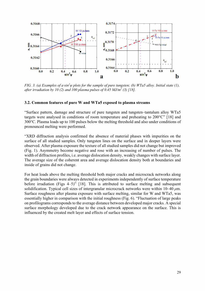
29
FIG. 3. (a) Examples of а·sin2ψ plots for the sample of pure tungsten; (b) WTa5 alloy. Initial state (1), after irradiation by 10 (2) and 100 plasma pulses of 0.45 MJ/m2 (3) [18].
3.2. Common features of pure W and WTa5 exposed to plasma streams
“Surface pattern, damage and structure of pure tungsten and tungsten–tantalum alloy WTa5 targets were analysed in conditions of room temperature and preheating to 200°C” [18] and 300°C. Plasma loads up to 100 pulses below the melting threshold and also under conditions of pronounced melting were performed.
“XRD diffraction analysis confirmed the absence of material phases with impurities on the surface of all studied samples. Only tungsten lines on the surface and in deeper layers were observed. After plasma exposure the texture of all studied samples did not change but improved (Fig. 1). Asymmetry become negative and rose with an increasing of number of pulses. The width of diffraction profiles, i.e. average dislocation density, weakly changes with surface layer. The average size of the coherent area and average dislocation density both at boundaries and inside of grains did not change.
For heat loads above the melting threshold both major cracks and microcrack networks along the grain boundaries were always detected in experiments independently of surface temperature before irradiation (Figs 4–5)” [18]. This is attributed to surface melting and subsequent solidification. Typical cell sizes of intergranular microcrack networks were within 10–40 μm. Surface roughness after plasma exposure with surface melting, similar for W and WTa5, was essentially higher in comparison with the initial roughness (Fig. 6). “Fluctuation of large peaks on profilograms corresponds to the average distance between developed major cracks. A special surface morphology developed due to the crack network appearance on the surface. This is influenced by the created melt layer and effects of surface tension.

30
FIG. 4. SEM images of the W tungsten surface exposed to 100 plasma pulses of 0.75 MJ/m2 each for different initial surface temperature (Tin): (a) Tin=20°C; (b) Tin=200°C. The length of the white marker line is 100 μm.
FIG. 5. SEM images of the WTa5 alloy surface exposed to 100 plasma pulses of 0.75 MJ/m2 each for different initial surface temperature: (a) Tin=20°C; (b) Tin=200°C. The length of the white marker line is 100 μm.
Plasma irradiation resulted in symmetrical tensile stress in the thin subsurface layer. The maximum residual stress in the plasma affected layer was reached after the first plasma pulses. Mass loss measurements demonstrated growing erosion with increasing energy load as in previous experiments. For targets irradiated with heat loads below melting threshold, mass losses mainly can be caused by sputtering. Surface melting leads to splashing of eroded material.
3.3. Features of pure W exposed plasma streams
Networks of macro cracks [23–32] developed on the surface of pure tungsten irradiated with 10 pulses of 0.45 MJ/m2 at an initial surface temperature at room temperature (Fig. 7(a)). A rise in irradiation pulses led to some growth of crack width and splitting of the crack mesh (Fig. 7b). Only a few isolated cracks appeared in some areas on the pre-heated surface exposed to a heat load below the melting threshold (Fig. 7(c)). With further increases of the number of plasma pulses both the width and depth of cracks increased, but new cracks did not appear (Fig.

31
7(d)). Cracks and growth of some edges of grains caused the development of the characteristic surface profile (Fig. 8(a)).
FIG. 6. (a) Surface profiles of samples W; (b) WTa5 development in the course of 100 plasma exposures, heat load Q=0.75 MJ/m2 [18].
FIG. 7. (a, c) SEM images of a pure tungsten surface exposed to 10 plasma pulses of 0.45 MJ/m2 each for different initial surface temperature; (b, d) 100 plasma pulses of 0.45 MJ/m2 each for different initial surface temperature. (a, b) Tin=20°C; (c, d) Tin=200°C. The length of the white marker line is 100 μm [18].

32
Measurements demonstrated that the maximal value, 300–400 MPa, of residual stress in the thin subsurface layer does not depend practically on initial target temperature, and it significantly grew with increasing thermal loads. Increasing the number of plasma pulses led to some relaxation of residual stress (Fig. 3(a)). Preheating the surface contributed to faster relaxation of residual stresses. Surface melting of the preheated surface caused the quickest relaxation of residual stresses” [18].
Samples of pure W were used for the high plasma load tests of up to 400 pulses. Before each plasma pulse, the surface temperature of all targets had been near room temperature.
The high number of plasma pulses resulted in surface modification [19–21]. The onset of melting at the edges of cracks was observed, whereas other surfaces did not melt (Fig. 9b). Melted edges eject nm particles. Such small particles are able to be melted even for rather small heat loads below the surface melting threshold [35]. Thus, surface modification may cause changes of the physical properties of the surface layer, thus influencing material behaviour under high plasma heat loads [33, 35]. Plasma irradiation resulted in a symmetrical tensile stress in the thin subsurface layer. Measurements demonstrated that the maximal value, ≈350 Mpa, of residual stress in the thin subsurface layer appeared as a result of the first plasma pulses. Increasing the number of plasma pulses led to some relaxation of residual stress up to ≈250 MPa. At the same time the microhardness of the exposed surface also decreased up to Hv=450 kg/mm2, initially 650 kg/mm2, with further increases of the exposure dose. This could be caused by annealing of vacancies in the structure. This agrees with slight increases of lattice parameters up to 0.31647 nm. Asymmetry became negative and rose with an increasing number of pulses. The width of the diffraction profiles, i.e. average dislocation density, weakly changed in the surface layer.
FIG. 8. (a) Surface profiles of samples W; (b) WTa5 development in the course of 100 plasma exposures, heat load Q=0.45 MJ/m2 [18].

33
FIG. 9. SEM images with different magnification of a pure tungsten surface exposed to 400 plasma pulses of 0.45 MJ/m2 each from Tin=20°C.
A near linear rise in roughness was observed under plasma irradiation with heat loads below the melting threshold. Maximal values of roughness parameters (Ra≈0.2 μm, Rz≈1.2 μm, Rmax≈1.7 μm) were received after 400 plasma pulses. Networks of macro cracks developed on the tungsten irradiated after 10 pulses of 0.45 MJ/m2. The rise in irradiation pulses led to some growth of crack width and splitting of the crack mesh (Fig. 9). Both the width and depth of some cracks increased. Cracks and growth at some grain edges caused the development of the surface profile.
3.4. Features of WTa5 exposed plasma streams
From an initial temperature at room temperature, only separate major cracks appeared on surfaces after the “first plasma pulses of 0.45 MJ/m2 (Fig. 10(a)). With increasing irradiation pulses the width of the cracks rose, but networks of cracks did not develop (Fig. 10(b)). Thus, for heat loads below the melting threshold without preheating, samples of WTa5 alloy demonstrated better resistance in comparison with pure tungsten” [18].
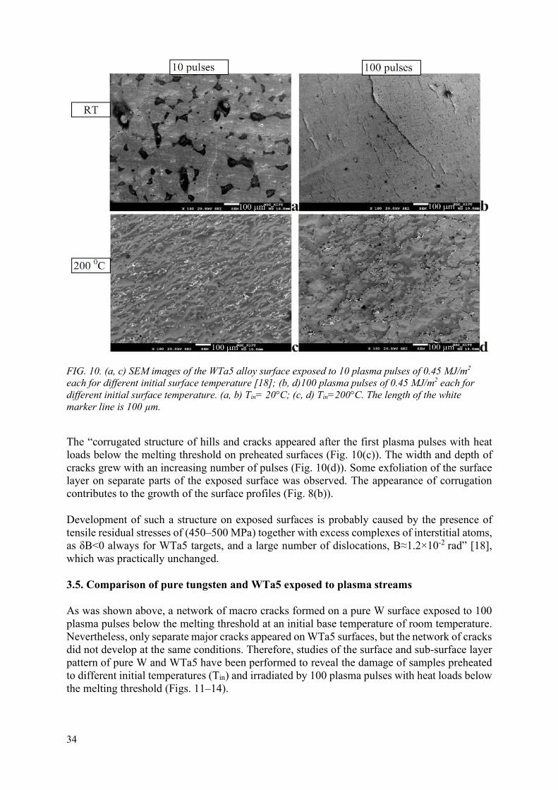
34
FIG. 10. (a, c) SEM images of the WTa5 alloy surface exposed to 10 plasma pulses of 0.45 MJ/m2 each for different initial surface temperature [18]; (b, d)100 plasma pulses of 0.45 MJ/m2 each for different initial surface temperature. (a, b) Tin= 20°C; (c, d) Tin=200°C. The length of the white marker line is 100 µm.
The “corrugated structure of hills and cracks appeared after the first plasma pulses with heat loads below the melting threshold on preheated surfaces (Fig. 10(c)). The width and depth of cracks grew with an increasing number of pulses (Fig. 10(d)). Some exfoliation of the surface layer on separate parts of the exposed surface was observed. The appearance of corrugation contributes to the growth of the surface profiles (Fig. 8(b)).
Development of such a structure on exposed surfaces is probably caused by the presence of tensile residual stresses of (450–500 MPa) together with excess complexes of interstitial atoms, as δВ<0 always for WTa5 targets, and a large number of dislocations, B≈1.2×10⁻² rad” [18], which was practically unchanged.
3.5. Comparison of pure tungsten and WTa5 exposed to plasma streams
As was shown above, a network of macro cracks formed on a pure W surface exposed to 100 plasma pulses below the melting threshold at an initial base temperature of room temperature. Nevertheless, only separate major cracks appeared on WTa5 surfaces, but the network of cracks did not develop at the same conditions. Therefore, studies of the surface and sub-surface layer pattern of pure W and WTa5 have been performed to reveal the damage of samples preheated to different initial temperatures (Tin) and irradiated by 100 plasma pulses with heat loads below the melting threshold (Figs. 11–14).

35
FIG. 11. SEM images of W surfaces exposed to 100 plasma pulses of 0.45 MJ/m2 each at (a) Tin=200°C (a); (b) Tin=300°C. The length of the marker line is 100 μm.
FIG. 12. SEM images of WTa5 alloy surfaces exposed to 100 plasma pulses of 0.45 MJ/m2 each at (a) Tin=200°C; (b) Tin=300°C. The length of the marker line is 100 μm.
The irradiation of pure W preheated to 200°C resulted in the appearance of only small isolated cracks on exposed surfaces (Fig. 11(a)). A corrugated structure of hills and cracks appeared on surfaces of WTa5 at the same base temperature (Fig. 12(a)). High exfoliation of the surface layer of WTa5 samples was also observed. The cross-sections showed the cracks’ appearance along the surface. The maximum depth of crack occurrence was almost 300 µm for pure W (Fig. 13(a)) and 200 µm for WTa5 (Fig. 14(a)).
SEM images demonstrated only small isolated cracks on exposed surfaces of pure W preheated to 300°C, whereas large isolated cracks were observed on exposed WTa5 surfaces (Fig. 11(b) and Fig. 12(b)). Plasma irradiation at an initial temperature of 300°C decreased the depth of cracks occurrence up to 200 µm for pure W (Fig. 13(b)). The cross-section of the WTa5 sample, however, shows some crack penetration from the surface to a depth of 2 mm (Fig. 14(b)).

36
FIG. 13. Cross-section of W targets exposed to 100 plasma pulses of 0.45 MJ/m2 each at (a) Tin=200°C (a); (b) Tin=300°C. The length of the marker line is 100 μm.
FIG. 14. Cross-section of the WTa5 alloy targets exposed to 100 plasma pulses of 0.45 MJ/m2 each at (a) Tin=200°C; (b) Tin=300°C. The length of the marker line is 200 μm.
3.6. Comparison with short pulse exposure
Non-textured rolled tungsten plates of Russian trademark and dimensions of 40×40×1 mm3 were examined to investigate the evolution of the structure and residual stresses in tungsten samples exposed to a small number of hydrogen or helium plasma impacts. All targets were exposed to perpendicular irradiation by powerful plasma streams generated by the QSPA Kh-50, PPA and MPC facilities.
Distinct networks of micro- and macrocracks were observed developing upon the “W surface after its irradiation within the QSPA at a heat load above the melting threshold. Typical mesh sizes of major cracks in the central area of the exposed surface were 0.8–1.3 mm. The crack width was estimated to be 4–8 µm after 20 pulses, as shown in Fig. 15. A typical cell size of an inter-granular microcrack mesh was 10–80 µm. The cell sizes were mostly within a 10–40 µm range, which corresponds to the grain size of this W grade.
Networks of major crack also formed on rolled tungsten surfaces. The size of such a crack mesh was 0.35–0.60 mm after exposure to PPA helium plasma and 0.25–0.70 mm after exposure to PPA hydrogen and helium plasma in the MPC facility. Crack width after short pulse exposure

37
was considerably larger, amounting to 5–15 µm, instead of 4–6 µm observed for the sintered W grade analysed after a similar number of QSPA pulses (Fig. 16).
FIG. 15. Width of cracks upon the tungsten surface as a function of the number of plasma pulses of 0.25 ms duration, at different QSPA heat loads [18].
FIG. 16. Width of cracks formed upon tungsten surfaces as a function of the number of plasma pulses at various heat loads, as observed for different W grades: for sintered tungsten samples within QSPA at 0.75 MJ/m2 (1) and 0.45 MJ/m2 (2), and for the rolled tungsten sample (3) at a heat load above the melting threshold within the PPA, MPC and QSPA facilities [18].
Distances between microcracks were 20–40 μm and 15–25 μm. The width of microcracks was approximately the same, as attributed to the re-solidification process and grain deformation. More fine cracks with a typical cell size of 2–7 μm appeared in the background of microcrack meshes (Fig. 17). The width of these cracks was about 0.5 µm. Blister-like and cellular-like structures appeared upon surfaces exposed to helium plasmas (Fig. 18), and some droplets of melted material were observed on the exposed surface (Fig. 17).
Symmetrical tensile stresses were created in the W surface layer as a result of plasma irradiation. In general, residual stress grew with an increase in the energy load. Similar to the sintered W targets, some relaxation of stresses was observed after a large number of pulses. The melting of the surface layer could essentially influence the relaxation of stresses, and the residual stress became very small after 20 pulses with observed melting.

38
For plasma loads below the melting threshold the residual stress was quite large, reaching a level of 200–250 MPa after 100 pulses. It needs to be noted that this value is still considerably smaller than that obtained for sintered tungsten after similar exposure. The magnitude of residual stresses for the deformed tungsten samples was smaller in comparison with those observed for the sintered samples and rolled W plates, which were investigated under similar conditions. This could be due to the combination of two different factors: the initial compressive stresses in the deformed W grade and its improved structure in comparison with the sintered and rolled W grades” [18].
FIG. 17. SEM images of the cracks formed upon the tungsten surface after 10 helium plasma pulses within MPC at 0.4 MJ/m2.

39
FIG. 18. SEM image of the cracks formed upon the tungsten surface after 10 helium plasma pulses within PPA at 0.4 MJ/m2.
4. EXPERIMENTAL STUDIES OF THE ALLOYING AND MODIFICATION OF EUROFER STEEL
“Surface modifications by powerful pulsed plasma streams were performed with the use of a QSPA Kh-50 quasi-stationary plasma accelerator and a MPC magneto-plasma compressor. Samples made of Eurofer alloy (Cr 9.7%, Mn 0.7%, Fe 89.6%) were prepared and delivered by the SCK•CEN Nuclear Research Centre in Belgium. All samples had sizes of 10×10×0.5 mm3. These samples were covered by tungsten coatings of about 3 μm in thickness, which were then deposited with a physical vapour deposition (PVD) technique [34] within a Bulat-type facility. Earlier such coatings were applied for estimation of their performance as plasma facing surfaces in comparison with monolithic tungsten targets. They enabled also an analysis of the adhesion properties of the PVD coatings and an investigation of the prospective PFCs for reactor first wall construction”1 [22].
The “values of the initial micro-hardness and roughness of the Eurofer samples amounted to 190 kg/mm2 and Ra<0.1 μm (Rmax≈0.1 μm), respectively. Surface profiles for these samples are shown in Fig. 19. During structural studies of sample surfaces lines corresponding to the α–Fe phase only were observed. It needs to be noted that to this phase is attributed the body centred cubic crystal structure. The results of the diffraction measurements are presented”1 in Fig. 20. The composition of Eurofer samples in their initial state and after processing is shown in Table 1.
The “surface morphology changed mainly due to the formation of plasma-melted layers. The roughness of the exposed surfaces increased up to Rmax≈0.3 μm”1. It needs to be noted that the micro-hardness of the modified surface of the Eurofer sample increased up to 260 kg/mm2 due to the stresses and quenching induced by the plasma treatment.
“The process of steel surface alloying consisted of two stages. During the first stage the tungsten coating was deposited upon the sample surface by means of the PVD method. After the deposition of tungsten coatings on the treated Eurofer surfaces their roughness slightly increased. During the second stage the W coated samples were exposed to five plasma pulses in the QSPA or MPC device”1.
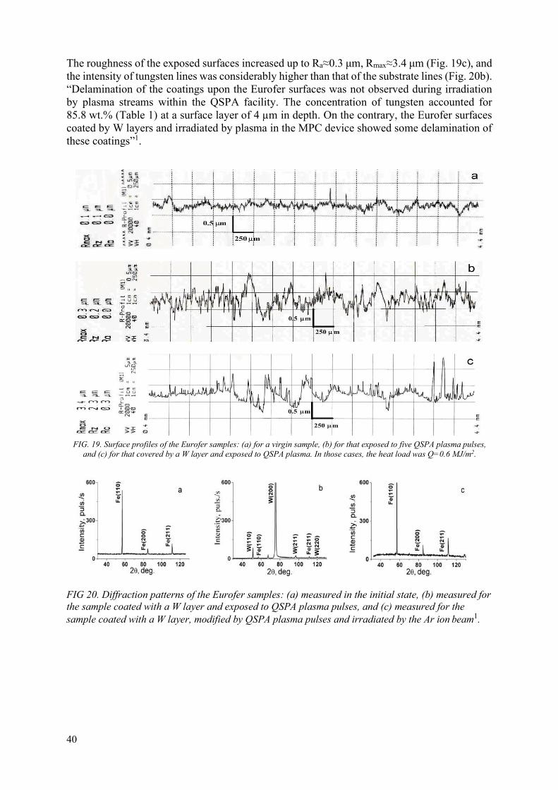
40
The roughness of the exposed surfaces increased up to Ra≈0.3 μm, Rmax≈3.4 μm (Fig. 19c), and the intensity of tungsten lines was considerably higher than that of the substrate lines (Fig. 20b). “Delamination of the coatings upon the Eurofer surfaces was not observed during irradiation by plasma streams within the QSPA facility. The concentration of tungsten accounted for 85.8 wt.% (Table 1) at a surface layer of 4 µm in depth. On the contrary, the Eurofer surfaces coated by W layers and irradiated by plasma in the MPC device showed some delamination of these coatings”1.
FIG. 19. Surface profiles of the Eurofer samples: (a) for a virgin sample, (b) for that exposed to five QSPA plasma pulses,
and (c) for that covered by a W layer and exposed to QSPA plasma. In those cases, the heat load was Q=0.6 MJ/m2.
FIG 20. Diffraction patterns of the Eurofer samples: (a) measured in the initial state, (b) measured for the sample coated with a W layer and exposed to QSPA plasma pulses, and (c) measured for the sample coated with a W layer, modified by QSPA plasma pulses and irradiated by the Ar ion beam1.

41
TABLE 1. ELEMENT CONTENT OF THE INVESTIGATED EUROFER SAMPLES1
The roughness of the exposed surfaces increased up to Ra≈0.3 μm, Rmax≈3.4 μm (Fig. 19c), and the intensity of tungsten lines was considerably higher than that of the substrate lines (Fig. 20b). “Delamination of the coatings upon the Eurofer surfaces was not observed during irradiation by plasma streams within the QSPA facility. The concentration of tungsten accounted for 85.8 wt.% (Table 1) at a surface layer of 4 µm in depth. On the contrary, Eurofer surfaces coated by W layers and irradiated by plasma in the MPC device showed some delamination of these coatings”1.
5. CONCLUSIONS
The performed experiments concentrated on comparative studies of plasma surface interaction features using different candidate materials of future fusion reactors under irradiation by high power plasma loads of variable parameters. The investigations aimed to support mainstream fusion research by testing radiation-resistant materials for large thermonuclear devices of both types, with magnetic and inertial plasma confinement, and for plasma technologies. The performed activity included adjustment of operational regimes of the QSPA Kh-50, Pulsed Plasma Gun and MPC devices to achieve adequate variation of energy and particle loads to the exposed candidate materials.
As the result of experiments on optimization of the PPA, QSPA Kh-50 and MPC devices, adjusting the operational regimes contributed adequate variation of energy and particle loads to the exposed candidate materials. A possibility of effective variation of energy loading to the processed sample surfaces was realized in two ways. First, changing the ion energy under constant plasma density was achieved by variation of the voltage between the accelerator electrodes. Secondly, changing the plasma density under constant ion energy was accomplished by placing the samples at different distances from the accelerator output.
Tungsten targets of different kinds, sintered, rolled and deformed, were tested using powerful plasma streams at different heat loads. Three plasma facilities, QSPA Kh-50, PPA and MPC, yielded the present results of tungsten irradiation experiments. “Two different crack meshes were identified after exposure to the tungsten samples. It was shown that major cracks do not depend on the tungsten grade. This was instead attributed to possible ductile-to-brittle transition effects. Meshes of inter-granular microcracks were detected at energy loads above the melting threshold, probably caused by the re-solidification process. Distinct droplets of melted material were observed upon the exposed surface in these conditions. Blister-like and cellular-like structures were observed upon surfaces exposed to helium and hydrogen plasma streams. Under
Sample Cr
(wt %)
Mn
(wt %)
Fe
(wt %)
W
(wt %)
Initial 9.7 0.4 89.9 ---- Coated with W + QSPA-plasma 1.3 ---- 12.95 85.8 Coated with W + QSPA-plasma + sputtered by the Ar-ion beam
8.9 0.36 89.64 1.1
Coated with W + MPC-plasma 9.7 0.4 88.8 1.1 Coated with W + sputtered by the Ar-ion beam 9.6 0.4 88.9 1.1

42
a large number of pulses, above 100, the width of macrocracks in the deformed tungsten targets was two times smaller than for the sintered and rolled targets. Thus, deformed W material was found to be more resistive against cracking as compare to other grades” [18].
Comparative experimental studies of macroscopic erosion of double forged pure tungsten and tungsten–tantalum alloy samples were performed with the QSPA Kh-50. With a heat load below the melting threshold macrocrack networks formed “only in the case of an initial target temperature at about room temperature on exposed surfaces of pure tungsten. Corrugated structures appeared on preheated surfaces of the tungsten–tantalum alloy after the first pulses and developed an increasing number of pulses. Further evolution of crack networks and a corrugated structure was accompanied by increases in crack width and swelling of crack edges.
Networks of micro- and macrocracks developed on surfaces of pure tungsten and tungsten–tantalum alloy as a result of surface irradiation with heat loads above the melting threshold. Surface modification and development of cracks led to increases in roughness of exposed surfaces. The micro deformations of pure tungsten and tungsten–tantalum alloy were similar for targets exposed in similar conditions. Residual stress grew with increases of the energy load. Relaxation of stresses was observed with an increasing number of pulses. Melting of the surface layer essentially added to the relaxation of stresses and increases to the absolute value of diffraction line asymmetry. This may be explained by increases in the number of interstitial complexes, which is consistent with a slight increase in the lattice parameter” [18].
A high number of repetitive plasma loads below the melting threshold led to clear degradation of thermo-mechanical properties of the affected surface layers of tungsten. Networks of cracks appeared on exposed surfaces. The onset of melting at crack edges was observed, whereas other surfaces did not melt. Melted edges ejected nm particles, which are able to melt even under rather small heat loads below the surface melting threshold. Surface modification and development of cracks led to increases of roughness of exposed surfaces. For both double forging pure tungsten and tungsten–tantalum alloy cracks propagated to the bulk mainly transversely and parallel to the irradiated surface.
The possibility of alloying RAFM steel “surfaces with tungsten coatings was demonstrated. An increase in the tungsten concentration was observed. The tungsten phase was identified together with some lines of the Fe phase upon the treated surfaces. The presence of the Fe phase created good conditions for tungsten penetration into the affected layer. The tungsten concentration achieved several wt.% in the surface layer at a thickness up to 4 µm. A maximum tungsten content of about 85 wt.% was observed in the surface layers of the Eurofer samples modified by plasma streams in the QSPA. Nevertheless, symmetrical tensile stresses up to 270 MPa were recorded in the near surface layer. As a result of the stress development, some delamination of the coatings during pulsed plasma irradiation was observed. The surface morphology changed mostly by melting and re-solidification of the surface layer. Macro- and microcracks appeared also on the modified surfaces. The sputtering yield for Eurofer steel samples modified by plasma streams was not very different from that observed for virgin samples. An explanation of such surface behaviour might be the accumulation of elastic energy in the stressed surface layer or poor adhesion of the modified tungsten coating to the steel substrates.
As a result of those effects some delamination of the coatings could develop. A possible way to improve coating resistance might be the application of several cycles of plasma treatment. During the first stage of such a cycle a tungsten coating of 1–2 µm in thickness needs to be deposited on the sample surface by the PVD method. During the second stage the coated

43
samples need to be processed with pulsed plasma streams. The reduction of coating thickness together with an increase in the number of plasma treatment cycles might create conditions for better penetration of an alloying element into the treated substrate”1.
ACKNOWLEDGEMENTS
This work has been performed in part within IAEA CRP 13016 and also partially supported by National Academy Science of Ukraine project X-4-3/2018, NMRT-2/2018 and П-5/24-2016.
REFERENCES
[1] SHOSHIN, A.A., BURDAKOV, A.V., CHEBOTAREV, V.V., GARKUSHA, I.E., IVANOV, I.A., KUKLIN, K.N. MAKHLAJ, V.A., MARCHENKO, A.K., POLOSATKIN, S.V., TERESHIN, V.I., Plasma-surface interaction during ITER Type 1 ELMs: Comparison of simulation with QSPA Kh-50 and the GOL-3 Facilities, Fusion Science and Technology 59 (2011) 57
[2] MARCHENKO, A.K., CHEBOTAREV, V.V., LADYGINA, M.S., GARKUSHA, I.E., PETROV, YU.V., SOLYAKOV, D.G., STALTSOV, V.V., TERESHIN, V.I., Compression zone formation in magnetoplasma compressor operating with heavy gases, Problems of Atomic Science and Technology, Series: Plasma Physics 6 (2010) 94-96.
[3] MALINOWSKI, K., CZAUS, K., SADOWSKI, M.J., SKLADNIK-SADOWSKA, E., GARKUSHA, I.E., TERESHIN, V.I., Experimental studies of ion emission from RPI IBIS facility and modelling of ion motions, Problems of Atomic Science and Technology, Series: Plasma Physics 6 (2010) 208-210.
[4] GARKUSHA, I.E., LANDMAN, I., LINKE, J., MAKHLAI, V.A., MEDVEDEV, A.V., MALYKHIN, S.V., CHEBOTAREV, V.V., PESCHANYI, S., PUGACHEV, A.T., TERESHIN, V.I., Performance of Deformed Tungsten under ELM-like Plasma Exposures in QSPA Kh-50, Journal of Nuclear Materials 415 (2011) S65–S69.
[5] PESTCHANYI, S., GARKUSHA, I., LANDMAN, I., Simulation of tungsten armour cracking due to small ELMs in ITER, Fusion Eng. and Design 85 (2010) 1697–1701
[6] MAKHLAJ, V.A., GARKUSHA, I.E., BYRKA, O.V., CHREBOTAREV, V.V., LANDMAN I.S., LEBEDEV, S.I., MALYKHIN, S.V., PUGACHEV, A.T., SHEVCHUK, P.B., TERESHIN, V.I., Influence of hydrogen and helium plasma streams exposures on modification of tungsten structure under powerful transient loads, Problems of Atomic Science and Technology, Series: Plasma Physics 1 (2011) 71-73.
[7] BANDURA, A.N., BYRKA, O.V., GARKUSHA, I.E., LADYGINA, M.S., MARCHENKO, A.K., PETROV, YU.V., SOLYAKOV, D.G., CHEBOTAREV, V.V., CHUVILO, A.A., Characteristics of plasma streams and optimization of operational regimes for magnetoplasma compressor, Problems of Atomic Science and Technology, Series: Plasma Physics 1 (2011) 68-70.
[8] MARCHENKO, A.K., GARKUSHA, I.E., CHEBOTAREV, V.V., LADYGINA, M.S., PETROV, YU.V., SOLYAKOV, D.G., TERESHIN, V.I., AKSENOV, N.N., STALTSOV, V.V., HASSANEIN, A., SKLADNIK-SADOWSKA, E., Features of plasma focus formation in different operation modes of gas-discharge magnetoplasma compressor, Acta Technica 56 (2011) 113-122.
[9] BYRKA, O.V., BANDURA, A.N., GARKUSHA, I.E., MAKHLAI, V.A., TARAN, V.S., TERESHIN, V.I., Application of pulsed plasma streams for surface modification of constructional materials, Acta Technica 56 (2011) 362-372.
[10] LADYGINA, M.S., GARKUSHA I.E., MARCHENKO, A.K., MAKHLAI, V.A., SADOWSKI, M.J., SKLADNIK-SADOWSKA, E., AKSENOV, N.N., TERESHIN, V.I., Spectroscopy of Plasma Surface Interaction in Experiments Simulating ITER Transient Events, Fusion Science and Technology 60 (2011) 27-33.
[11] MAKHLAJ, V.A, Characterization of QSPA plasma streams in plasma-surface interaction experiments: Simulation of ITER disruption, Problems of Atomic Science and Technology, Series: Plasma Physics 6 (2012) 126.

44
[12] BAZDYREVA, S.V., GARKUSHA, I.E., MAKHLAJ, V.A., MALYKHIN, S.V., PUGACHОV, A.T., The influence of irradiation by hydrogen plasma on the structure and phase composition Ti-Zr-Ni alloys containing quasicrystalline phase, Problems of Atomic Science and Technology, Series: Plasma Physics 6 (2012) 226.
[13] CHEBOTAREV, V.V., CHEREDNYCHENKO, T.N., ELISEEV, D.V., GARKUSHA, I.E., KOZLOV, A.N., KULIK, N.V., LADYGINA, M.S., MARCHENKO, A.K., MORGAL, YA.I., PETROV, YU.V., SOLYAKOV, D.G., STALTSOV, V.V., MHD Characteristics of compression zone in plasma stream generated by MPC, Problems of Atomic Science and Technology, Series: Plasma Physics 6 (2012) 123
[14] MAKHLAJ, V.A., GARKUSHA, I.E., AKSENOV, N.N., CHUVILO, A.A., LANDMAN, I.S., High-speed monitoring of dust particles in ITER ELMs simulation experiments with QSPA Kh-50, Acta Polytechnica 53 (2013) 193–196.
[15] MAKHLAJ, V.A., AKSENOV, N.N., BYRKA, O.V., GARKUSHA, I.E., BIZYUKOV, A.A., BIZYUKOV, I.A., GIRKA, O.I., SEREDA, K.N., BAZDYREVA, S.V., MALYKHIN, S.V., PUGACHOV, A.T., Combined exposures of tungsten by stationary and transient hydrogen plasmas heat loads: Preliminary results, Problems of Atomic Science and Technology 1 (2013) 70.
[16] BANDURA, A.N., BYRKA, O.V., CHEBOTAREV, V.V., GARKUSHA, I.E., MAKHLAY, V.A., TERESHIN, V.I., SKOBLO, T.S., PUGACH, S.G., Alloying and modification of structural materials under pulsed plasma treatment, International J. Plasma Environmental Sci. and Technology 5 (2011) 2-6.
[17] MARCHENKO, A.K., CHEBOTAREV, V.V., LADYGINA, M.S., GARKUSHA, I.E., PETROV, YU.V., SOLYAKOV, D.G., STALTSOV, V.V., TERESHIN, V.I., Compression zone formation in magnetoplasma compressor operating with heavy gases, Problems of Atomic Science and Technology, Series: Plasma Physics 6 (2010) 94-96
[18] MAKHLAJ, V.A., GARKUSHA, I.E., AKSENOV, N.N., BAZYLEV, B., LANDMAN, I., LINKE, J., MALYKHIN, S.V., PUGACHOV, A.T., SADOWSKI, M.J., SKLADNIK-SADOWSKA, Е., WIRTZ, M., Tungsten damage and melt losses under plasma accelerator exposure with ITER ELM relevant conditions, Physica Scripta T159 (2014) 014024.
[19] KRIVOGLAZ, M.A., X ray and Neutron Diffraction in Nonideal Crystals, Springer-Verlag Berlin Heidelberg (1996).
[20] COENEN, J. W., ANTUSCH, S., AUMANN, M. Materials for demo and reactor applications-boundary conditions and new concepts, Phys. Scr. T167 (2016) 014002.
[21] SUGIYAMA, K., SCHMID, K., JACOB, W., Sputtering of iron, chromium and tungsten by energetic deuterium ion bombardment, Nuclear Materials and Energy 8 (2016) 1-7.
[22] GARKUSHA, I.E., AKSENOV, N.N., BYRKA, O.V., MAKHLAJ, V.A., HERASHCHENKO, S.S., MALYKHIN, S.V., PETROV, YU.V., STALTSOV, V.V., SUROVITSKIY, S.V., WIRTZ, M, LINKE, J, SADOWSKI, M.J., SKLADNIK-SADOWSKA, E., Simulation of plasma–surface interactions in a fusion reactor by means of QSPA plasma streams: recent results and prospects, Phys. Scr. 91 (2016) 094001.
[23] HERASHCHENKO, S., AKSENOV, N., BIZYUKOV, I., GIRKA, O., MAKHLAJ, V., MALYKHIN, S., SUROVITSKIY, S., BIZYUKOV, A., SEREDA, K., Erosion features of tungsten surfaces under combined steady-state and transient plasma loads, Problems of Atomic Science and Technology, Series: Plasma Physics 6 (2016) 69-72
[24] MAKHLAJ, V., AKSENOV, N., BYRKA, O., CHUNADRA, A., HERASCHENKO, S., MALYKHIN, S., MIKHAILOV, I., SEREDA, K., SUROVITSKIY, S., GARKUSHA I., Alloying and modification of stainless steel by powerful plasma streams, Problems of Atomic Science and Technology, Series: Plasma Physics 6 (2016) 129-132
[25] MAKHLAI, V.A., GARKUSHA, I.E., LINKE, J., MALYKHIN, S.V., AKSENOV, N.N., BYRKA, O.V., HERASHCHENKO, S.S., SUROVITSKIY, S.V., WIRTZ M., Damaging of tungsten and tungsten–tantalum alloy exposed in ITER ELM-like conditions, Nuclear Materials and Energy 9 (2016) 116-122.
[26] HERASHCHENKO, S.S., MAKHLAJ, V.A., AKSENOV, N.N., BYRKA, O.V., CHEBOTAREV, V.V., KULIK, N.V., LEBEDEV, S.I., SHEVCHUK, P.B., STALTSOV, V.V.

45
Damage of 3D tungsten targets in the course of ITER ELM-like heat loads, Problems of Atomic Science and Technology, Series: Plasma Physics 1 (2017) 119-122.
[27] BYRKA, O.V., AKSENOV, N.N., HERASHCHENKO, S.S., MAKHLAJ, V.A., TARAN, V.S., TIMOSHENKO O.I. Surface modification and droplet formation under exposures of tungsten coatings with ELM-like transient loads, Problems of Atomic Science and Technology, Series: Plasma Physics 1 (2017) 115-118.
[28] MALYKHIN, S.V., SUROVITSKIY, S.V., MAKHLAJ, V.A., AKSENOV, N.N., BYRKA, O.V., BORISOVA, S.S., HERASHCHENKO, S.S., RESHETNYAK, V.V., Structure evolution of tungsten coatings exposed to plasma flows under ITER ELM relevant conditions, Problems of Atomic Science and Technology, Series: Plasma Physics 1 (2017) 123-125.
[29] MALYKHIN, S.V., GARKUSHA, I.E., MAKHLAY, V.A., SUROVITSKY, S.V., RESHETNYAK, M.V., BORISOVA, S.S., On application of X ray approximation method for studying the substructure of sufficiently perfect samples, Funct. Mater. 24 (1) (2017) 179-183.
[30] MAKHLAI, V.A., HERASHCHENKO, S.S., AKSENOV, N.N., BYRKA, O.V., GARKUSHA, I.E., MALYKHIN, S.V., SUROVITSKIY, S.V., KULIK, N.V., STALTSOV, V.V., LEBEDEV, S.I., SHEVCHUK, P.V., WIRTZ, M., SADOWSKI, M.J., Erosion properties of tungsten and WTa5 alloy exposed to repetitive QSPA plasma loads below melting threshold, Problems of Atomic Science and Technology 6 (118) (2018) 59-62.
[31] GARKUSHA, I., MAKHLAJ, V., BYRKA, O., TARAN, V., VOITSENYA, V., MALYKHIN, S., HERASHCHENKO, S., SUROVITSKIY, S., NOWAKOWSKA-LANGIER, K., SADOWSKI, M.J., SKLADNIK-SADOWSKA, E., TERENTYEV, D., Materials surface damage and modification under high power plasma exposures, Journal of Physics: Conf. Series 959 (2018) 012004.
[32] VOLKOVA, Y.E., SOLYAKOV, D.G., CHEREDNYCHENKO, T.N., LADYGINA, M.S., MARCHENKO, A.K., PETROV, YU.V., CHEBOTAREV, V.V., MAKHLAJ, V.A., YELISEYEV, D.V., Control of the compression zone position in plasma streams generated by MPC, Problems of Atomic Science and Technology 6 (118) (2018) 127-130.
[33] GARKUSHA, I.E., MAKHLAI, V. A., AKSENOV, N. N., BAZYLEV, B., LANDMAN, I., SADOWSKI, M., SKLADNIK-SADOWSKA, E., Tungsten Melt Losses Under QSPA Kh-50 Plasma Exposures Simulating ITER ELMs and Disruptions, Fusion Science and Technology 65 (2014) 186.
[34] TERESHIN, V.I., BANDURA, A.N., BYRKA, O.V., Coating deposition and surface modification under combined plasma processing, Vacuum 73 (2004) 555–560.
[35] RATYNSKAIA, S., TOLIAS, P., BYKOV, I. Interaction of adhered metallic dust with transient plasma heat loads, Nucl. Fusion 56 (2016) 066010.

46
MULTIDIMENSIONAL ANALYSIS OF INERTIAL FUSION DEVICES RELEVANT MATERIALS IRRADIATED WITH HIGH ENERGY PLASMA BEAMS WITH PLASMA FOCUS DEVICE K. LAAS*, T. LAAS*, J. PAJU*, V. SHIROKOVA**, J. PRIIMETS*, ***, B. VÄLI* * Tallinn University, School of Natural Sciences and Health, *** Tallinn University of Technology, Estonian Maritime Academy, Tallin Email: [email protected] ** Tallinn University of Technology, Virumaa College, Kohtla-Järve Estonia Abstract
In the current research inertial fusion-related deuterium plasma and materials interaction in studied. Pure double forged tungsten, single forged tungsten and tungsten alloy with iron and nickel content are used as plasma facing materials. The synergetic effects generated on the surfaces of the materials by the irradiation with small number (2-10) of pulses of very powerful plasma and ion fluxes, combined with 25-50 weak plasma pulses are investigated. Analysis of the surfaces of the irradiated samples reveal that the density of surface cracks depends on the content of tungsten in the sample. Analysis of the defects within bulk, using measurements of electric conductivity or micro-hardness, indicate that specimens irradiated at first with very powerful plasma pulses are more damaged than the others, even if the characteristic defects on the surfaces are similar. As a novel method the multifractal formalism for the study of damaged surfaces is proposed. An analysis indicates, that the distribution of different kinds of damages on the surfaces of the irradiated materials, behave as multifractals – thus, the generalized multifractal dimension allows distinguishing the samples that have been irradiated with different plasma regimes.
1. INTRODUCTION
Due to excellent thermo-mechanical properties tungsten (W) is the most promising material for armor and plasma shielding in fusion devices – be it in case the wall of the chambers of nuclear fusion reactors with inertial plasma confinement, or critical parts of the magnetic confinement devices e.g. divertor of ITER [1–3], or other fusion devices under development. Though, one of the main problems with pure tungsten is its brittleness [1]. Irradiation of tungsten with high density and high temperature plasma pulses leads evantually to development of cracks’ mesh (macro- and micromesh) on the surface. The problems related to materials science (especially the questions considering the improvement of tungsten’s properties) are relevant to all future fusion devices. Namely: i) how does the long-lasting irradiation and the heat loads that are generated within the fusion devices affect the functional (armor) and construction materials; ii) why do the defects (e.g. mesh of cracks, pores, wavelike structures, exfoliations, bubbles etc) form, both on the irradiated materials surface and also in the bulk of the material. A universal parameter for characterizing the effect of heat and particle flow falling on the material has previously been proposed, by Hirai and Pintsuk [4] as the heat flux factor (or damage factor)
𝐹 = 𝑞 ∙ 𝜏 , where q - power flux density, - interaction time. This parameter may be the same for different most violent events in different kind of plasma devices. The aforementioned predicted reference values for different fusion devices are as follows: 100–500 MW s1/2 m-2

47
for HiPER [5] and up to 103 MWs1/2 m-2 for NIF [6], and for ITER the values are as follows: edge-localized modes (ELMs), 20–60 MWs1/2 m-2, disruptions 100–200 MWs1/2 m-2 [3].
Therefore, the damages’ dependence on plasma and heat wave parameters has to be determined. In addition, the development of new methods for estimating the bulk defects based on the information derived from the surface defects is important for fusion devices and also other technologies. It is of utmost importance to carry out investigations by different types of devices, including dense magnetized plasma devices, e.g. Plasma Focus device (PF), which can generate very short and powerful heat and plasma pulses with heat flux factor values comparable for the ones of the Inertial Confinement Devices (ICD) or Magnetic Confinement Devices (MCD).
It needs to also be noted, that the impact of the duration of the plasma pulses' is not thoroughly investigated regarding the generation of the surface and bulk damages. As results gained for plasma-focus devices from PF-1000U facility have shown, powerful and very short (10–30 ns) ion fluxes generate shock-waves that have the capability of propagating through the material that is being irradiated [7]. Calculations show that the depth of such shock waves can reach up to 0.8 mm. Such cooperative effect between the heat and the mechanical shock-wave, which can be modelled as Gaussian white noise and shot-noise, has also been predicted theoretically [8, 9]. This indicates that despite the fact that of some of the needed properties of plasma-facing materials are commonly shared within the magnetic and inertial confinement devices, a need for research carried out by devices, which can generate very short plasma and ion pulses, exists.
Until now, mostly a qualitative analysis of the materials surface damages has been applied. Using quantitative parameters (e.g. micro-roughness and micro-hardness) mainly single-type structures or damages can be described. For estimating the damages within the bulk of the material, means of micro-hardness and electrical conductivity can be used. Unfortunately, such analysis does not necessarily allow the distinction between different kinds of defects, which can result of different effects of plasma, ions and irradiation. In order to carry out quantitative analysis, which will enable the distinction between either different kind of defects or defects with different characteristic sizes, the multifractal formalism is proposed [10, 11]. The main problem is to obtain correlations between: (i) the multifractal characteristics; (ii) materials’ mechanical properties; and (iii) plasma parameters in the PF device (i.e. power flux density, pulse duration, temperature on the target surface, plasma shell velocity, plasma and fast ions energy [12, 13]). This formula allows applying the methods of fractal geometry to estimate the radiated materials’ damages by relying on the images of the samples. The various structures of the defects and randomly located elements on the surfaces of the irradiated materials occur due to stochastic phenomena taking place in the flow of plasma and irradiation.
2. SETUP OF THE EXPERIMENTAL STUDY
The main interest in the experimental part of the research was in the study of the development of damages, during the irradiation of the samples with two series of short and powerful plasma-ions streams on several different materials: (i) double forged tungsten (DFW) – manufactured at PLANSEE; (ii) single-forged tungsten (W), manufactured at PLANSEE; (iii) tungsten alloy with 2% nickel and 1% iron and (HPM1850) and 3.33% nickel and 1.67% iron (HPM1800, HPM1810) – manufactured at H.C. Starck. In the current research the combined effects of series of plasma pulses with different plasma parameters (characterized mainly by the heat flux factor or the damage factor of the plasma). Thus, the samples were irradiated twice. At first, during the irradiation series a, the samples were irradiated with plasma streams with power flux densities 500–10000 MW/cm2 and pulse duration 50–100 ns accompanied with ion fluxes with
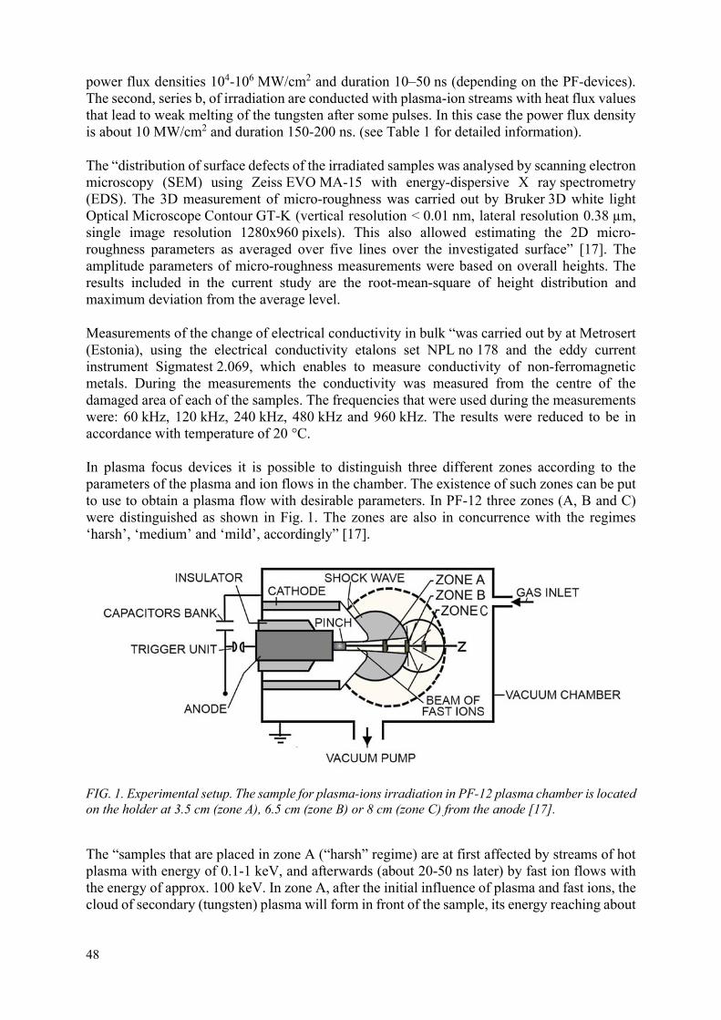
48
power flux densities 104-106 MW/cm2 and duration 10–50 ns (depending on the PF-devices). The second, series b, of irradiation are conducted with plasma-ion streams with heat flux values that lead to weak melting of the tungsten after some pulses. In this case the power flux density is about 10 MW/cm2 and duration 150-200 ns. (see Table 1 for detailed information).
The “distribution of surface defects of the irradiated samples was analysed by scanning electron microscopy (SEM) using Zeiss EVO MA-15 with energy-dispersive X ray spectrometry (EDS). The 3D measurement of micro-roughness was carried out by Bruker 3D white light Optical Microscope Contour GT-K (vertical resolution < 0.01 nm, lateral resolution 0.38 µm, single image resolution 1280x960 pixels). This also allowed estimating the 2D micro-roughness parameters as averaged over five lines over the investigated surface” [17]. The amplitude parameters of micro-roughness measurements were based on overall heights. The results included in the current study are the root-mean-square of height distribution and maximum deviation from the average level.
Measurements of the change of electrical conductivity in bulk “was carried out by at Metrosert (Estonia), using the electrical conductivity etalons set NPL no 178 and the eddy current instrument Sigmatest 2.069, which enables to measure conductivity of non-ferromagnetic metals. During the measurements the conductivity was measured from the centre of the damaged area of each of the samples. The frequencies that were used during the measurements were: 60 kHz, 120 kHz, 240 kHz, 480 kHz and 960 kHz. The results were reduced to be in accordance with temperature of 20 °C.
In plasma focus devices it is possible to distinguish three different zones according to the parameters of the plasma and ion flows in the chamber. The existence of such zones can be put to use to obtain a plasma flow with desirable parameters. In PF-12 three zones (A, B and C) were distinguished as shown in Fig. 1. The zones are also in concurrence with the regimes ‘harsh’, ‘medium’ and ‘mild’, accordingly” [17].
FIG. 1. Experimental setup. The sample for plasma-ions irradiation in PF-12 plasma chamber is located on the holder at 3.5 cm (zone A), 6.5 cm (zone B) or 8 cm (zone C) from the anode [17].
The “samples that are placed in zone A (“harsh” regime) are at first affected by streams of hot plasma with energy of 0.1-1 keV, and afterwards (about 20-50 ns later) by fast ion flows with the energy of approx. 100 keV. In zone A, after the initial influence of plasma and fast ions, the cloud of secondary (tungsten) plasma will form in front of the sample, its energy reaching about

49
100 eV. During approximately 0.1 ms, the energy of secondary plasma decreases to about 2 eV. Nevertheless, the degraded influence of the secondary plasma may last up hundreds of microseconds.
The samples placed in zone B (“medium” regime) are reached by plasma and fast deuterons simultaneously. The duration of impact of both slow plasma and fast ions increases (100 and 50 ns accordingly at PF-12, but it depends on the device). When the flow of fast ions reaches the plasma sheath, the angle of ion flux widens from initial 3-5o to approx. 30o.
When a sample is placed inside the area with the widened flux, zone C (“mild” regime), the fast ions’ influence on the sample’s surface decreases significantly compared to the effect that occurs in zone B because of the decrement of power flux density of fast ions. In zone C the flow of fast ions reaches the sample first, and after that the slow plasma arrives” [17].
Three different irradiation regimes at PF-12 are characterized by heat flux factor defined as F = q1/2, where q – plasma’s heat flux density, - duration of plasma-materials interaction, were used. The different regimes at PF-12 device were acquired by placing the sample at different distances from the anode (Fig. 1). In the current study three different distances were used: (i) 9.5 cm from the anode with heat flux factor of plasma 40-45 MWs1/2m-2 – mild regime, (ii) 6.5 cm from the anode with heat flux factor of plasma 150-170 MWs1/2m-2 – medium regime, (iii) 3.5 cm from the anode with heat flux factor of plasma approx 103 MWs1/2m-2 – harsh regime. In PF-6 (see Fig. 2) the heat flux factor varied from 110 to max. 2000 MWs1/2m-2 depending of the quality of the plasma/ions pulse – medium/harsh regime. The distance of the sampled from the anode was about 7.5 cm.
FIG. 2. A photo of the PF-6 discharge chamber fitted to the material science experiments.
3. STUDY OF IRRADIATED SAMPLES
The irradiation of each of the tungsten and tungsten alloy “samples was carried out in two separate series of experiments using plasma-ion pulses with different plasma and heat flow parameters. For that, three different plasma-focus devices were used: PF-12 at Tallinn University (TU), PF-6 and PF-1000U at Institute of Plasma Physics and Laser Microfusion, Warsaw (IPPLM)” [17] in co-operation with researchers from IPPLM and A.A. Baikov Institute of Metallurgy and Material Sciences, Russia (IMET). In all of the PF-devices deuterium was used as the work gas. An overview of the irradiation conditions on different devices and main characteristic damages on the specimens are shown in Table 1. Notice that

50
samples irradiated with the first series (series a) of plasma pulses are denoted with ‘a’ and samples denoted with ‘b’ are the same samples after the second series (series b) of plasma pulses.
3.1. Analysis and description of changes on the surface of irradiated double forged tungsten samples
Irradiated surfaces of DFW were investigated by SEM. In the characterization of the damages on the samples the term micro- and macro-cells are used. A “macro-cell is defined as an area bordered by so called macro cracks (with width up to 2 m) and a micro-cell is an area bordered with micro cracks (with width about 10–50 nm)” [17].
It needs to be noted that on the backscattered electron SEM images, of samples placed at the zone C at PF-12, “some darker regions may occur, as the samples may be covered with thin copper films originating from the anode. Therefore, the original micro cracks on the surface of the samples may not be very well” [17] observable (due to the copper film). Nevertheless, the development of the mesh of micro cracks can be distinguished, the higher structures (extending upward), and macro cracks of tungsten are not influenced by the copper.
The “analysis of the generation of cracks (Fig. 3 and Table 1) shows that the series of plasma pulses in the harsh regimes (high power flux density, but short interaction time, on PF-1000U, PF-6, zones A)” [17] lead to the generation and development of meshes of macro cracks. Typically, the dimensions of macro cracks after 10 or 50 pulses at PF-6 will range 200–300 µm. In case of the samples that have been irradiated with either 2 or 4 pulses of very powerful plasma fluxes, at PF-1000U (samples DFW-2a and DFW-3a), the size of a macrocell is about 1100-1400 µm (the micro cracks are absent). Although very powerful yet very short plasma pulses can lead to the development of droplets and erosion of some material, the fast heating-cooling cycles create only a small amount of macro cracking.
Second irradiation of the samples with low plasma flux density pulses leads to further deterioration, by increased “development of the mesh of macro cracks (whereas the size of macro-cells is about 200-320 µm with exceptions” [17] in cases of the samples DFW-3b and DFW-4b, where the average sizes are about 130 and 170 µm accordingly). It needs to also be noted that irradiation with second series of plasma pulses leads to the development of a mesh of micro cracks on samples. The size of the microcells ranges from 20 to 40 µm.

51
TABLE 1. IRRADIATION CONDITIONS AND THE ESTIMATED DAMAGES. EACH SAMPLE HAS BEEN IRRADIATED TWICE – DURING SERIES A AND B
Sample number with the reference to the irradiation series (a or b)
Number of pulses/regime during the irradiation series
Plasma: Fast ions Micro-roughness
average (Ra) /top (Rt) (difference of peak height and valley depth), (µm)
Defects/characteristic size of the defects (µm)
Description of the main defects Power flux
density q (MWm-2)
Power flux density q (MWm-2)
Pulse duration (µs)
Pulse duration (µs)
Heat flux factor F (MWs1/2m-
2)
Heat flux factor F (MWs1/2m-
2)
DFW-1a 2 (PF-1000U)/ harsh
107-108 109-1010 2.23/63.24 Size of micro-cells 1689 µm, size of macro-cells 51222 µm.
Mesh of macro- and micro cracks, W wave traces, grooves, macro cracks, strong Cu traces.
0.1 0.05
DFW-4a 4 (PF-1000U)/ harsh
3000-30000 105-106 0.85/22.91 Size of micro-cells 11712 µm, size of macro-cells 40941 µm
Mesh of macro- and micro cracks, Molten surface, droplets, bubbles, craters, cracks, weak Cu traces.
DFW-2a
10 (PF-6)/ medium-harsh
106-107 108- 109
1.89/52.95 Size macro-cells approx 1400 µm.
Mesh of macro cracks only, W wave traces, some droplets.
DFW-3a 1.50/36.01 Size of macro-cells approx 1100 µm.
Mesh of macro cracks only, strong wave traces, erosion traces, droplets, macro cracks, weak Cu traces.
HPM1800-1a
2.79/34.25 Elongated droplets with width 32±6 µm and length 41±6 µm.
Some cracks surrounding the droplets with cell size 48-60 μm. Some cavities between the droplets and near the cracks. No developed mesh of cracks.
HPM1800-2a
2.62/29.57
HPM1810-3a
0.05
0.01-0.02 1.79/32.62 Elongated droplets
with width 24±4 µm and length 32±11 µm.
Some cracks around and over droplets. Mesh of cracks is not developed. Some cavities between the droplets and near the cracks.
HPM1810-4a
1.61/31.84
HPM1850-5a
200-2000
3.03/33.21 Low bumps with
dimensions 45-50 µm. Several droplets on top bumps with diameter about 10-12 µm.
Occasional cracks over the surface. No mesh of cracks. HPM1850-
6a 104-105
2.79/35.33

52
TABLE 1. CONTINUED
Sample number with the reference to the irradiation series (a or b)
Number of pulses/regime during the irradiation series
Plasma: Fast ions Micro-roughness
average (Ra) /top (Rt) (difference of peak height and valley depth), (µm)
Defects/characteristic size of the defects (µm)
Description of the main defects Power flux
density q (MWm-2)
Power flux density q (MWm-2)
Pulse duration (µs)
Pulse duration (µs)
Heat flux factor F (MWs1/2m-
2)
Heat flux factor F (MWs1/2m-
2)
DFW-1b
105 107
1.72/53.6 Size of micro-cells 1028 µm, size of macro-cells of cracks 36541 µm.
Mesh of macro- and micro cracks, molten layer. Strong Cu traces, which have partly covered the micro cracks.
DFW-2b 2.87/58.2 Size of micro-cells 576 µm, size of macro-cells 38427 µm.
Mesh of macro- and micro cracks, bubbles, droplets.
DFW-3b 1.25/15.8 Size of micro-cells 494 µm, size of macro-cells1157 µm.
Mesh of macro- and micro cracks, droplets, strong erosion traces, Cu traces.
DFW-4b
0.15-0.20 0.05
1.42/31.7 Size of micro-cells 8113 µm, size of macro-cells 32135 µm.
Mesh of macro- and micro cracks, strong Cu traces.
HPM1800-1b
2.45/37.5 Droplets with diameter 14-19 µm.
Some larger (macro)-cracks with characteristic cell size 100±20 µm. Mesh of micro cracks with characterisitc cell size about 50±14 µm.
HPM1800-3b
50 (PF12) / mild
40-45 2103
2.20/30.85 Elongated (melted) droplets with width about 7-9 µm and length 25 ±4 µm.
Mesh of macro cracks with characteristric cell size 85±23 µm. Developing mesh of micro cracks with characteristic cell size 20-40 µm.
HPM1800-5b
2.92/40.0 Wavelike droplets with diameter 40-50 µm. Droplets or bumps with diameter 2-3 µm on top of waves.
Mesh of macro cracks with cell size 40-60 µm. Also, mesh of developing micro cracks with cell size varying from 4 to 10 µm.
HPM1800-2b
5105 108
2.79/37.58 Strong melting traces with some droplets on the traces with diameter about 20 µm.
Cracks with length up to 80 µm. No developed mesh of macro cracks. Beginning of the development of mesh of micro cracks with cell size 20-40 µm.
HPM1810-4b
50 (PF12) / medium
0.1-0.15 0.03
1.67/29.17 Marks of droplets (lowerered and melted) with diameter about 20 µm.
Cracks with length 80-100 µm. Beginning of the development of mesh of micro cracks with cell diameter 20-40 µm and mesh of macro cracks.
HPM1850-6b
150-170 1.7104
3.13/40.52 Droplets with diameter 20-30 µm. Some droplets or bumps with diameter 2-3 µm on top of waves.
Some parts are covered with mesh of macro cracks with cell size 80-100 µm. Beginning of the development of mesh of micro cracks with cell size about 20-40 µm.
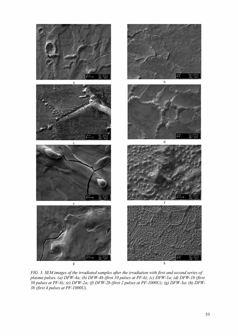
53
a
b
c
d
e
f
g
h
FIG. 3. SEM images of the irradiated samples after the irradiation with first and second series of plasma pulses. (a) DFW-4a; (b) DFW-4b (first 10 pulses at PF-6); (c) DFW-1a; (d) DFW-1b (first 50 pulses at PF-6); (e) DFW-2a; (f) DFW-2b (first 2 pulses at PF-1000U); (g) DFW-3a; (h) DFW-3b (first 4 pulses at PF-1000U).

54
“It was observed that all samples have practically identical damage features: wavelike structures, micro- and macro cracks formation, melting traces, cavities etc. Though, the density of different kind of damages (ratio of total area of specific kind of defects to the total area of investigated surface, determined by SEM images) depends strongly on plasmas’ and ions’ flows power flux densities. High heat loads result in droplets formation and possible material ejection from the sample from the tungsten’s surface, with the simultaneous movement of the molten layer (see Fig. 3 (b), (e), (f)). Closer exploration of the SEM images shows that droplets are located next to cavities, holes or cracks (Fig. 3(b)); therefore, the possibility of droplets’ emanation from the grooves or cracks cannot be overlooked. EDS analysis revealed that while the smoother parts of the surface may contain some copper, the droplets, blisters and grooves contain almost no copper at all.
Irradiation of DFW samples, which have previously been irradiated with high deuterium plasma pulses with higher power flux densities, later on with 50 pulses of quite low deuterium plasma pulses (q=10 MW/cm2)” [17] leads to the generation of droplets and bubbles and development of mesh of cracks (see Fig. 3 (b), (d), (f), (h)). When the same irradiation conditions and amount of pulses is applied on polished pure single forged tungsten specimens, mild melting traces are generated. Therefore, we have concluded: “1) influence of the first series, rather shocking plasma pulses, changes the surface of DFW in such a way that irradiation of the same surface with low plasma flux densities (low heat flux factor) may lead to significant amplifying of damages; 2) while the impact of the fast deuteron flux leads to the implantation of deuterium atoms into the materials, the influence of plasma pulses with low power flux densities lead to the evaporation of the implanted deuterium, which changes the tungsten’s’ surface significantly” [17].
In the Fig. 4, the 3D profilometry images of the same specimens are shown. In general, the average micro-roughness of samples irradiated at either PF-6 (10 or 50 pulses) or at PF-1000U (2 and 4 pulses) do not differ much from each other – the values of Ra vary from 0.85 to 2.23 µm. “Thus, irradiation with either a small number of pulses or with the mild regime of plasma, does not affect the average value of micro-roughness” [17] strongly. The sum of the most extreme values of valley depth and peak height of the defects Rt on the sample is in general not correlated with average micro-roughness (Ra) as the eminent deviations might not occur in the areas of measurements. Even though, Rt may increase about 1.4 times in some cases (e.g. DFW-3), “in general, the irradiation of the damaged samples with a series of plasma pulses in the mild regime may lead to decrease” [17] of Rt, as was the expected result. The deterioration of the surface damages that have evolved during the treatment with harsh plasma is not significant during further irradiation in the mild regime.
The “study of 3D micro-roughness images reveals another point – in all cases the irradiation of the samples with the secondary series of plasma pulses in the mild regime leads to an increase of dimensions of the cavities. Although the average micro-roughness of the samples does not increase, more defects with much extreme values of valley depth and peak height might occur on the double irradiated samples. It can be concluded that, as the surface is already damaged, the following series of plasma pulses lead to the erosion of the material” [17] only to be drifted elsewhere to form bigger conglomerations. The results of such processes are not revealed by SEM images.

55
a
b
c
d
e
f
g h
FIG. 4. The 3D micro-roughness profiles measured with Bruker 3D white light Optical Microscope Contour GT-K. (a) DFW-1a; (b) DFW-1b (first 10 pulses at PF6); (c) DFW-4a; (d) DFW-4b (first 50 pulses at PF-6); (e) DFW-2a; (f) DFW-2b (first 2 pulses at PF1000U); (g) DFW-3a; (h) DFW-3b (first 4 pulses at PF-1000U).

56
3.2. Changes in the of irradiated double forged tungsten samples characterized by “conductivity measurements
“The analysis of electrical conductivity measurements reveals the impact of the mechanical shockwave of the plasma impulses on the material. The reference value for electrical conductivity of pure double forged tungsten is 18.3 MS/m that has been measured during the experiments. The electrical conductivity has been measured” [17] in all of the tungsten samples after both series of irradiations. The samples containing iron and nickel have not been measured, as the methodology of analysis enables to measure only non-ferrous metals.
It “can be seen from the Fig. 5 that the most significant change of conductivity appeared in the samples irradiated with the harsh plasma regime” [17] (the samples DFW-2a and DFW-3a). In the samples irradiated with plasma in the medium regime (samples DFW-1a and DFW-4a) only minute “changes were registered. The most damaged sample was DFW-2b in case of which the measured damages went as deep as 520 μm from the surface. The average depth of damages in the second series of experiments was 500 μm. As the sample DFW-2 has the greatest change of conductivity values and the lowest value of conductivity after the second series of irradiation, it is the most damaged sample. Considering the irradiation process the sample was manipulated with, the biggest difference between this sample and DFW-3 (that has received similar treatment) is the relative quality of the impulses that affected the samples. The output of neutrons during the two plasma pulses on the sample DFW-2 was 2-3 times higher” [17] than in case of plasma pulses received by the sample DFW-3. Therefore, the impact of fast ions was much higher in case of the plasma pulses on the sample DFW-3. Therefore, the primary damages of the sample DFW-2 were extensive, further damages cumulated and the sample deteriorated during the second series of irradiation.
“As the impact of fast ions in the zone C at PF-12 is much weaker than in zone A at PF-6 and PF-1000U, it was assumed that the irradiation of the samples with second series of plasma pulses in mild regime does not lead to significant change of the damages in the bulk of material. The results of samples DFW-1 and DFW-4 are in accordance with that. But in case of samples” [17] DFW-2 and DFW-3, the irradiation at mild regime on PF-12 (where the fast ions power flux density is low) the sample’s material in the bulk continually deteriorates.
The “change of conductivity of the tungsten can be explained by considering that conductivity of a solid material depends on the concentration of point defects” [17], microcracks, dislocations and other occurring bulk defects. Cooperative experiments with the teams of IPPLM and IMET have shown, that powerful ion beams generate shock-waves penetrating into and through the materials (depending on their thickness). This phenomenon was also theoretically shown by Latyshev et. al [7]. It has been shown, that the “pressure of the shock–wave, due to fast ions, can reach 20 GPa in the bulk. It can go as deep as 500-800 m inside the bulk, depending on the initial power flux density of fast ions on the samples’ surface. The shock-waves lead to the generation of defects and also, to the weakening of the ties between the” [17] microcrystals. Such defects are not apparent when studying the cross-sections of the irradiated samples with SEM.

57
100 200 300 400 500 6006
8
10
12
14
16
18
Co
nduc
tivity
(M
S/m
)
Depth d (m)
DFW1b DFW2b DFW3b DFW4b DFW1a DFW2a DFW3a DFW4a
µ µ
FIG. 5. Electrical conductivity of the DFW samples irradiated with two series of plasma pulses at different plasma-focus devices and regimes.
3.3. The analysis of the irradiated tungsten alloy samples’ surfaces from SEM images
The tungsten alloy samples HPM1800, HPM1810, HPM1850 were also at first irradiated with plasma and fast ions pulses in the regime in harsh regime and later in mild or medium regimes (see Fig.1 and Table 1).
In all the samples the first serie of irradiation led to the melting of the surface layer, development of the droplets and cracks on the surface after repeated heating-cooling cycles. The comparison of the panels in Fig. 6 indicates that the characteristic size of droplets and bumps generated due to surface melting depends of content of tungsten (see also Table 1). On the surfaces of samples made of HPM1800 (95%W, 3.33%Ni, 1.67%Fe) and HPM1810 (95%W, 3.33%Ni, 1.67%Fe), the elongated droplets have formed with width of 32 µm and length 41 µm on HPM1800 and width of 24 µm and length 32 µm on HPM1810.. On samples of HPM1850, where the content of tungsten is the highest (97%W, 2%Ni, 1.%Fe), only occacional circular droplets with the diameter of ~10 µm excist. Instead of larger droplets on HPM1850 samples lower, wave-like structures (bumps) have formed with size ~50 µm. It needs to also be noted that the developed structures on the surfaces of the irradiated samples are mainly W, as the EDS measurements have not shown any increase of Fe or Ni in comparison with the non-irradiated specimens.

58
a b
c
FIG. 6. SEM images of the samples after first irradiation serie of 10 pulses on PF-6 with heat flux factor of plasma about 200 MWs1/2m-2. (a) HPM1800-1a (95%W,3.33%Ni,1.67%Fe); (b) HPM1810-3a (95%W,3.33%Ni,1.67%Fe); (c) HPM1850-5a (97%W,2%Ni,1Fe).
Careful examination of SEM images shows that some microcracks occur, mainly in the close vicinity of the droplets or bumps (conglomerations), but distinctive meshes of cracks have not developed. No macro cracks are visible. In Fig. 6(c), the beginning of the development of a mesh of cracks, with cell size about 120–140 µm, can be detected on the surfaces of HPM1850 samples.

59
a b
c d
e f
FIG. 7. SEM images of the samples after second irradiation serie of 50 pulses on PF12 with heat flux factor of plasma about 40-45 MWs1/2m-2 in mild regime: (a) HPM1800-1b; (c) HPM1810-3b; (e) HPM1850-5b. 50 pulses in medium regime with heat flux factor of plasma about 150-170 MWs1/2m-2: (b) HPM1800-2b; (d) HPM1810-4b; (f) HPM1850-6b.
After the second irradiation, in the mild regime on PF-12, on the samples HPM1800-1 and HPM1850-5 (Fig. 7(a),(e)) the original droplets previously visible in Fig. 6 have been eroded, leading to the decrease of their height. On the sample HPM1800-3 (Fig. 3(c)) the melting and erosion of material during irradiation with second series of plasma in mild regime has led to the joining of the droplets.

60
Due to higher heat load during the 50 pulses of the irradiation cycle, the dominant process on the surface of samples HPM1800-2, HPM1810-4 and HPM1850-6 (panels b, d and f on Fig 3 accordingly) in comparison with the afforementioned samples HPM1800-1, HPM1810-3, HPM1850-5 has been melting. Also, while in case of the samples HPM1800-2 and HPM1800-4 the original defects have been melted, on the sample of HPM1850-6 some new bumps have been generated with diameter about 2–3 µm.
Heating-cooling cycles of secondary irradiation have led to the beginning of the development of mesh of macro- and microcracks in all the samples. However, due to higher heat load, the characteristic cell size of the samples HPM1800-2, HPM1810-4 and HPM1850-6 are smaller. It needs to also be mentioned that the closer examination shows that the mesh of microcracks is more developed in the samples of the material HPM1850 that has higher content of tungsten.
The 3D images of the surfaces of the irradiated specimens, received from 3D white light Optical Microscope, reveal the same characteristic defects as the images from SEM, but in bigger scale (see Figs 8, 9). It needs to also be noted that deeps or ridges with sharp walls are not shown correctly here. However, the height of the droplets and the depth of tre cavities can be better estimated by 3D profilometry. On the other hand, the 3D profilometry can not show the existence of cracks and small holes.

61
a
b
FIG. 8. 3D profilometry images of samples (a) HPM1800-2a; (b) HPM1850-6a after first irradiation series.
Comparison of the 3D profilometry images, 2D traces and SEM images shows that typical diameter of droplets (bumps) seen at Fig. 8(b) and Fig. 9 is ~40 µm. However, on SEM images mainly the highest tops can be distinguished, with the diameter ~20 µm. While some of the specimens have peaks on droplets, on the other samples the droplets (see Fig. 8(b), Fig. 9(b)) on the surface are streched out in some direction. This indicates that plasma in mild or medium regime has eroded the initial droplets to some direction. This is in accordance with the obtained SEM images. The forming process of the wave-like droplets during the first series of irradiation might be due to development of Kelvin-Helmholtz instabilities within the surface layer of the irradiated specimens.
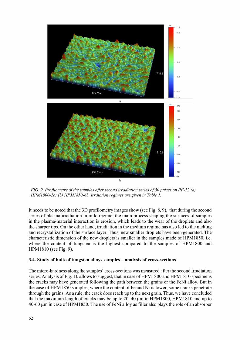
62
a
b
FIG. 9. Profilometry of the samples after second irradiation series of 50 pulses on PF-12 (a) HPM1800-2b; (b) HPM1850-6b. Irrdiation regimes are given in Table 1.
It needs to be noted that the 3D profilometry images show (see Fig. 8, 9), that during the second series of plasma irradiation in mild regime, the main process shaping the surfaces of samples in the plasma-material interaction is erosion, which leads to the wear of the droplets and also the sharper tips. On the other hand, irradiation in the medium regime has also led to the melting and recrystallization of the surface layer. Thus, new smaller droplets have been generated. The characteristic dimension of the new droplets is smaller in the samples made of HPM1850, i.e. where the content of tungsten is the highest compared to the samples of HPM1800 and HPM1810 (see Fig. 9).
3.4. Study of bulk of tungsten alloys samples – analysis of cross-sections
The micro-hardness along the samples’ cross-sections was measured after the second irradiation series. Analysis of Fig. 10 allows to suggest, that in case of HPM1800 and HPM1810 specimens the cracks may have generated following the path between the grains or the FeNi alloy. But in the case of HPM1850 samples, where the content of Fe and Ni is lower, some cracks penetrate through the grains. As a rule, the crack does reach up to the next grain. Thus, we have concluded that the maximum length of cracks may be up to 20–40 µm in HPM1800, HPM1810 and up to 40-60 µm in case of HPM1850. The use of FeNi alloy as filler also plays the role of an absorber

63
of the shocks, that have been generated by the strong shock waves (pulses) that have been induced by either the fast ions or the plasma streams. It needs to also be mentioned, that though the melting and evaporison temperature of both Fe and Ni are lower than of W, no deep holes between tungsten grains occur – thus, the iron and nickel have not evaporated out of the bulk.
a
b
c
d
FIG. 10. SEM images of cross-sections of tungtsten alloy samples irradiated with two series of plasma pulses. HPM1850 – bigger grains with characteristic size 50-60µm; HPM1800, HPM1810 – smaller size 30-40µm. (a) HPM1800-2b; (b) HPM1800-4b; (c) HPM1850-5b; (d) HPM1850-6b.
The average micro-hardness of non-irradiated tungsten alloy is about 3400-3600 MPa, which is less than the value for the pure W (about 5000 MPa). Fig. 11 indicates that the surface layer has decreased hardness. In case of alloys HPM1800 and HPM 1810 the thickness of the layer with decreased hardness reaches approx. 50 µm in depth, whereas in HPM1850 samples to 80 µm depth. Thus, the thickness of the layer of decreased hardness depends again on the content of W; but in general, it does not exceed the depth of 2 grain diameter. The higher content of W content leads to the increase of the brittless and therefore, also to the decrease of resilience to the powerful pulses of heat and mechanical shockwaves.

64
0 100 2001500
2000
2500
3000
3500
4000H
ardn
ess
(M
Pa)
Depth (µm)
HPM1800-1b HPM1810-3b HMP1850-5b
a
0 100 200
2400
2600
2800
3000
3200
3400
3600
3800
Har
dne
ss (
MP
a)
Depth (µm)
HPM1800-2b HPM1810-4b HPM-1850-6b
b
FIG. 11. Micro-hardness of the samples irradiated with two series, measured fron cross-sections. (a) Samples irradiated with 10 pulses at PF-6 and 50 pulses in mild regime at PF-12; (b) Samples irradiated with 10 pulses at PF-6 and with 50 pulses in medium regime at PF-12.
3.5. Study of pure tungsten
For comparison, also some pure tungsten samples were investigated. The emphasis on this part of the study was to obtain information of how their damages evolve after receiving only a few (2) high power density plasma pulses accompanied with high density ion streams, and also a bigger number (25) of low power density plasma pulses. The order of high and low power flux density plasma pulses varied from sample to sample. “Thus, a hypothesis was proposed – the order of succession of plasma pulses with different characteristics impacts the overall damages that emerge on the sample. Though a lot of research has been done to estimate the damage induced by mild pulses, it is probable that occasional harsh pulses can damage samples more thoroughly, causing a remarkable accumulation of damages even if the samples are henceforth irradiated only with mild pulses” [18]. The mirror-polished tungsten (>99.97%W, manufactured by PLANSEE, (~1015 mm2 and ca 1.93 ± 0.043 mm thick)) samples were irradiated on PF-12, with deuterium as a working gas. All of the samples received 27 pulses with two different plasma flux values, thus in two different regimes (harsh and mild, see Fig.1). The combined effect of different plasma fluxes was obtained by varying the timing when harsh regime is implemented during the irradiation cycle. The research was conducted by measuring electrical conductivity of the material, analysing the SEM images and micro-hardness of sample’s cross-sections. The results were then combined to find a correlation between the changes of conductivity and micro-hardness.

65
TABLE 2. IRRADIATION CYCLES ON EACH OF THE SAMPLES AND THEIR EFFECT ON THE SAMPLE [18]
Sample Wmix1 Wmix2 Wmix3**
Order of succession of different regimes (No of pulses in each regime)
Mild (25) +
Harsh (2)
Harsh (2) +
Mild (25)
Mild (12) + Harsh (2) + Mild (13)
Depth of visible damages from the surface, obtained from cross-sections’ SEMs (μm)
90 100 80
Depth of the layer with decreased micro-hardness(μm) *
117 125 113
The plateau value of the micro-hardness (st dev) (MPa);
the range of depth where it was measured from (μm)
3640(120); 25-55
1290(120); 50-85
3080(350); 30-80
The maximal depth where long horizontal cracking was either seen or induced during micro-hardness measurements (μm)
130 370 300
Average lengths of macro-cells' dimensions on the surface (μm):
Average of the minimal length (st dev); Average of the maximal length (st dev)
Min: 530(170);
Max: 1390(560)
Min: 580(140);
Max: 1300(430)
Min:510(130);
Max: 1510(640)
Range of dimensions of macro-cells (μm): 240 – 3220 290 – 2200 310 – 3000
Description of the damages Mesh of macro cracks is not very developed. Surface is not evenly covered with macro-cells. The cells are not well-defined. Parts of sample are covered with Cu.
Mesh of cracks is well developed. Many macro-cells are visible. Cracks are wider than in other samples.
The mesh of cracks has developed more than in case of Wmix1 but less than in sample Wmix2.
* Two or more subsequent points have values less than ~95% of the reference value. ** The first two measuring points on Wmix3 have been excluded from the analysis as they were poorly positioned on the sample and thus are not considered representative for the sample.

66
3.5.1. Results of measurements of electrical conductivity
In Fig. 12 “the change of conductivity depending on the depth of the samples is shown. The reference value of conductivity for current samples of W is σWref = (18.42 ± 0.08) MS/m, obtained during our measurements (5 measurements in different depths, with 95% confidence level). The graphs in Fig. 12 suggest that the most damaged sample was Wmix2 which received 2 harsh pulses before irradiation with series of mild plasma pulses, and least damaged was sample Wmix1, which received 2 harsh pulses after the irradiation with series of mild plasma pulses.
The results indicate that the decrease of conductivity is directly related to the succession of used regimes during the irradiation. The harsh plasma pulses accompanied with powerful ion pulses generate mechanical shock waves through the bulk of the material, which deteriorate the material by affecting the crystal structure of the material, thus inflicting further decrease of electrical conductivity even if mild irradiation regime influences the sample afterwards. The measurements show that in the depth of 150 μm from the surface, the electrical conductivity of the most damaged sample, Wmix2, has decreased about 14.1%. The decrease in Wmix3 and Wmix1 is about 8.0% and 5.9%, accordingly” [18]. As expected, value of thermal conductivity is related to electrical conductivity by Wiedemann-Franz law, it can be concluded that the thermal conductivity decreases also accordingly. “Thus, our experiment shows that also the heat conductivity factor may decrease up to 14% in near-surface layer due to effect of interplay with two series of plasma pulses” [18].
FIG. 12. Conductivity values (MS/m) in depth (μm) of the samples.
3.5.2. Measurements of micro-hardness
In Fig. 13 “the change of micro-hardness values in depth of the samples is shown. The reference value” [18] of micro-hardness for tungsten was 509,01±9 HV0.500 Although, the SEM images do not reveal any visual damages (macro cracks) beyond 100 μm inside the bulk of the sample, the process of measuring the micro-hardness values damaged the sample’s (Wmix2) material by inducing cracks, parallel to the surface, hence producing unreliable data
The “plateaus and a layer of decreased hardness that reaches as deep as 100–150 μm are visible in Fig. 12. The micro-hardness values for the plateaus are (average; standard deviation) as

67
follows: Wmix1 (3640; 120), Wmix2 (1290; 120), and for Wmix3 (3080; 350). After the plateaus, the values of micro-hardness start growing. The values below are given according to following order: Wmix1 (25+2); b) Wmix2 (2+25); c) Wmix3 (12+2+13).
As the micro-hardness normalizes in the bulk (i.e. two or more subsequent points have values no less than ~95% of the reference value) the extension of damages reaches 117, 125 and 113 μm. Going even deeper from those depths, the average value of micro-hardness for each sample is comparable to the reference value HVWref = (4993 ± 63) MPa. The normalized micro-hardness and its standard deviation (latter in brackets) for each sample then are 4890(130), 4980(110) and 4910(240) MPa” [18].
Nevertheless, such phenomenon of the generation of the layer with decreased micro-hardness has also been found previously in several materials (within W, WL10 and stainless steel; with the thickness of the zone approximately 250 μm) that have been irradiated in intermediate (medium) regime, varying amounts of “pulses and with different working gases (deuterium in case of tungsten samples with different processing; hydrogen and nitrogen in case of stainless steels)” [14,15,18].
FIG. 13. Results of micro-hardness analysis of the samples.
3.6. Conclusions
Comparison with research on single forged tungsten shows that double forging of tungsten has led to improvement of the materials properties, namely – strengthening of the binding between grains. Thus, the development of mesh of cracks happens due to powerful plasma pulses. Also, mesh of cracks develops when numerous plasma pulses affect the material. “Irradiation of samples, which have previously been irradiated with high heat flux factor deuterium plasma pulses with higher power flux densities, further with 50 pulses of quite low heat flux factor deuterium plasma pulses” [17] leads to the generation of bubbles and development of cracks’ mesh (see Figs 3(b), (d), (f), (h)). Therefore: (i) the “influence of the first rather shocking plasma pulses change the surface of DFW in such a way that irradiation of the same surface with low plasma flux densities (low heat flux factor) may lead to significant amplifying of damages; (ii) while impact of fast deuteron flux leads to implantation of deuterium atoms into the materials,

68
the influence of plasma pulses with low power flux densities lead to evaporation of implanted deuterium, which changes the tungsten’s’ surface significantly.
Analysis of the 3D measurements of the samples reveals that the average micro-roughness of the samples irradiated with different conditions (different power flux densities of fast ions and plasma, duration of plasma) does not differ significantly. Also, the influence of second series of plasma pulses in mild regime does not lead to essential changes of average micro-roughness. The study of 3D micro-roughness images reveals that in all cases the irradiation of the samples with secondary series of plasma pulses in the mild regime leads to an increase of dimensions of the hollows. Therefore, while the average micro-roughness of the irradiated sample does not increase, there may be more defects which are much higher than the average height (depth) of the double irradiated samples. It can be concluded that while the surface is already damaged, the following series of plasma pulses lead to erosion of the material” [17] and the material’s drift to forming bigger conglomerations.
Analysis of the change of electrical conductivity in double forged tungsten “reveals that the bulk of material will be significantly damaged by very powerful streams of fast ions (power flux density up to 105–106MW/cm2). Irradiation of the samples with plasma and fast ions with lower power flux density (about 104 MW/cm2) does not lead to big decrease of conductivity in the bulk. Irradiation of the same samples with second series of plasma in mild regime leads to further deterioration of the already damaged samples, while the conductivity does not change on the samples” [17] irradiated with plasma streams and fast ions with power flux density about 104 MW/cm2. Therefore, one can conclude that in the case of double forged tungsten even only a few (2-4) very powerful plasma and fast ions pulses may lead to damaging of the sample, which deteriorates even more within the bulk due to succeeding weak plasma pulses.
Comparison of our results – more specifically the change of micro-hardness through the cross-section of irradiated samples of tungsten alloys (HPM1800, HPM1810, HPM1850) – indicates that the thickness of the layer of decreased hardness (50–80 µm) depends on the content of Fe and Ni. The generation of such a layer is in accordance with earlier results carried out under similar conditions. For example, in pure W samples such layer may reach up to 250 µm and in WL10 (tungsten doped with 1% lanthanum-oxide) even up to 500 µm. [14,15]
The bigger content of tungsten in alloys leads to an increase of number of sharp tips. Such behavior of tungsten-based alloys is also characteristic for samples manufactured by other methods.. E.g. in case of the pure tungsten samples, manufactured by either single or double forging, the distance between sharp tips is shorter than in case of HPM1850 or HP1800, or tungsten doped with lanthanum-oxide [14–16]. Thus, as the rise of such sharp tips may be due to a source of impurities when tungsten-based alloys is used as armour material of fusion device. So the adding of Fe-Ni with small content might be adviseable.
“We have found that the succession of mild and harsh pulses on a sample impacts the development of damages inside the sample – the samples that receive powerful pulses at the beginning of the irradiation cycle deteriorate more, compared to the samples that receive powerful pulses later on during the irradiation. The deterioration is observable by using different methods that describe the damages in various depths i.e. measuring micro-hardness or electrical conductivity or by analysing SEM images of cross-sections – the changes occur according to the order of succession of plasma pulses with different characteristics. It is also evident that the analysis of SEM imaging and micro-hardness measurements are insufficient, as they cannot describe the material in such depth as electrical conductivity suggests the scope
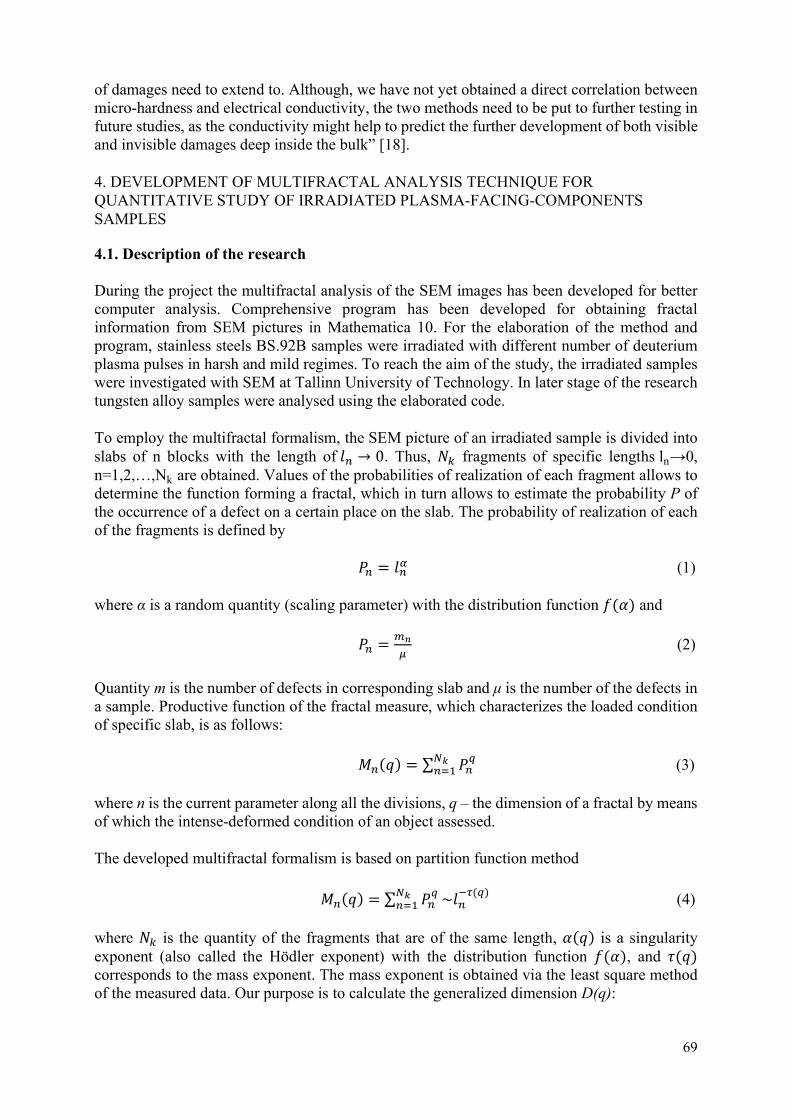
69
of damages need to extend to. Although, we have not yet obtained a direct correlation between micro-hardness and electrical conductivity, the two methods need to be put to further testing in future studies, as the conductivity might help to predict the further development of both visible and invisible damages deep inside the bulk” [18].
4. DEVELOPMENT OF MULTIFRACTAL ANALYSIS TECHNIQUE FOR QUANTITATIVE STUDY OF IRRADIATED PLASMA-FACING-COMPONENTS SAMPLES
4.1. Description of the research
During the project the multifractal analysis of the SEM images has been developed for better computer analysis. Comprehensive program has been developed for obtaining fractal information from SEM pictures in Mathematica 10. For the elaboration of the method and program, stainless steels BS.92B samples were irradiated with different number of deuterium plasma pulses in harsh and mild regimes. To reach the aim of the study, the irradiated samples were investigated with SEM at Tallinn University of Technology. In later stage of the research tungsten alloy samples were analysed using the elaborated code.
To employ the multifractal formalism, the SEM picture of an irradiated sample is divided into slabs of n blocks with the length of 𝑙 → 0. Thus, 𝑁 fragments of specific lengths ln→0, n=1,2,…,Nk are obtained. Values of the probabilities of realization of each fragment allows to determine the function forming a fractal, which in turn allows to estimate the probability P of the occurrence of a defect on a certain place on the slab. The probability of realization of each of the fragments is defined by
𝑃 = 𝑙 (1)
where α is a random quantity (scaling parameter) with the distribution function 𝑓(𝛼) and
𝑃 = (2)
Quantity m is the number of defects in corresponding slab and μ is the number of the defects in a sample. Productive function of the fractal measure, which characterizes the loaded condition of specific slab, is as follows:
𝑀 (𝑞) = ∑ 𝑃 (3)
where n is the current parameter along all the divisions, q – the dimension of a fractal by means of which the intense-deformed condition of an object assessed.
The developed multifractal formalism is based on partition function method
𝑀 (𝑞) = ∑ 𝑃 ~𝑙( ) (4)
where 𝑁 is the quantity of the fragments that are of the same length, 𝛼(𝑞) is a singularity exponent (also called the Hödler exponent) with the distribution function 𝑓(𝛼), and 𝜏(𝑞) corresponds to the mass exponent. The mass exponent is obtained via the least square method of the measured data. Our purpose is to calculate the generalized dimension D(q):

70
𝐷 =( )
(5)
and the multifractal spectrum 𝑓(𝛼) vs 𝛼, which can give the information about frequent as well as rare and also smooth defects, correlations and capacity dimension of multifractal structure.
Multifractal spectrum is calculated by the Legendre transform
𝑓 𝛼(𝑞) = 𝑞𝛼(𝑞) − 𝜏(𝑞) (6)
where the singularity exponent 𝛼(𝑞) yields as
𝛼(𝑞) = (7)
To apply the Legendre transform, the following requirement has to be fulfilled
> 0 (8)
i.e. the mass exponent needs to be convex function.
4.2. Results and conclusion
4.2.1 Analysis of the irradiated stainless-steel samples
Elaborated code has enabled to calculate the mass exponents 𝜏(𝑞), generalized fractal dimension 𝐷 and scaling parameter α(q) with its distribution function 𝑓(𝛼). This has been done on the SEM images that have been converted from grayscale to black and white. In Fig. 14 four processed pictures of radiated stainless steel samples are shown, where the contrast and brightness have been changed. These pictures were analysed by the compiled program in Mathematica 10.
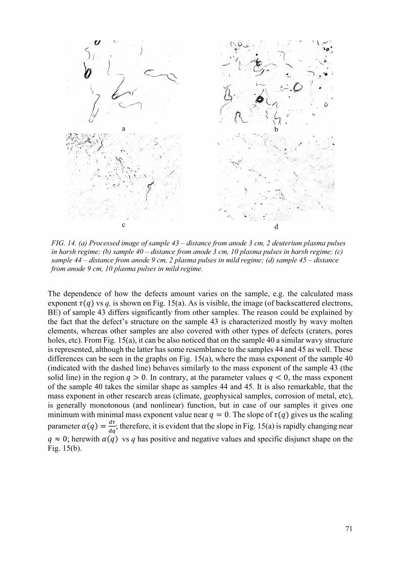
71
a
b
c
d
FIG. 14. (a) Processed image of sample 43 – distance from anode 3 cm, 2 deuterium plasma pulses in harsh regime; (b) sample 40 – distance from anode 3 cm, 10 plasma pulses in harsh regime; (c) sample 44 – distance from anode 9 cm, 2 plasma pulses in mild regime; (d) sample 45 – distance from anode 9 cm, 10 plasma pulses in mild regime.
The dependence of how the defects amount varies on the sample, e.g. the calculated mass exponent 𝜏(𝑞) vs q, is shown on Fig. 15(a). As is visible, the image (of backscattered electrons, BE) of sample 43 differs significantly from other samples. The reason could be explained by the fact that the defect’s structure on the sample 43 is characterized mostly by wavy molten elements, whereas other samples are also covered with other types of defects (craters, pores holes, etc). From Fig. 15(a), it can be also noticed that on the sample 40 a similar wavy structure is represented, although the latter has some resemblance to the samples 44 and 45 as well. These differences can be seen in the graphs on Fig. 15(a), where the mass exponent of the sample 40 (indicated with the dashed line) behaves similarly to the mass exponent of the sample 43 (the solid line) in the region 𝑞 > 0. In contrary, at the parameter values 𝑞 < 0, the mass exponent of the sample 40 takes the similar shape as samples 44 and 45. It is also remarkable, that the mass exponent in other research areas (climate, geophysical samples, corrosion of metal, etc), is generally monotonous (and nonlinear) function, but in case of our samples it gives one minimum with minimal mass exponent value near 𝑞 = 0. The slope of 𝜏(𝑞) gives us the scaling
parameter 𝛼(𝑞) = ; therefore, it is evident that the slope in Fig. 15(a) is rapidly changing near
𝑞 ≈ 0; herewith 𝛼(𝑞) vs q has positive and negative values and specific disjunct shape on the Fig. 15(b).

72
a
b
FIG. 15. Multifractal parameters of the analysed samples. (a) The mass exponent 𝜏(𝑞) vs q; (b) scaling parameter 𝛼(𝑞) vs q. Sample 43 - solid line, sample 40 - dashed line, sample 44 - dotted line, and sample 45 - dot-dashed line.
Analysis of the generalized multifractal dimension Dq shows (see Fig. 16(a)), that all four surface structures can be described by multifractals (otherwise graphics need to be linear and horizontal). Moreover, the generalized fractional dimensions of all samples show non-monotonous increasing dependence. Distribution of singularity spectrum 𝑓(𝛼(𝑞)) vs 𝛼(𝑞) on Fig. 16(b) shows a strong multifractal behavior in the case of all samples.
A
b
FIG. 16. Multifractal parameters of the analysed samples. (a) Generalized multifractal dimension Dq vs q; (b) distribution function 𝑓(𝛼) of scaling parameter α(q). Sample 43 - solid line, sample 40 - dashed line, sample 44 - dotted line, and sample 45 - dot-dashed line.
In conclusion, we have compiled a program, which calculates the multifractal measures of the irradiated samples. Results also show, that irradiated samples can be described by multifractal analysis; thus, the method has promising features indicating it could be used as a statistical tool for comparing damaged surfaces of different samples (tungsten, steel, its alloys, etc). Moreover, as can be seen from Figs 15–16, the shape of distribution function as well as the generalized multifractal dimension, as function of dimension of fractal q, is different for sample 43 which has distinguished melting traces (see Fig. 16(a)). In this way the shape of the generalized multifractal dimensions vs parameter q allows to distinguish the character of different damages on the sample.
4.2.2 Analysis of the irradiated tungsten alloy samples
We have also analysed HPM1800, HPM1810 and HPM1850 samples after irradiation with the second series of plasma pulses, using SEM images (see Fig. 6).

73
In Fig. 17(a) the dependence of the generalized dimension D(q) on parameter q is shown. As the dependence is not linear and, in several cases, it is non-monotonic, the distribution of the damages on the surface of the irradiated materials have definitely multifractal character. It can be also seen, that the type of multifractal (increasing or decreasing sigmoid or non-monotonous dependence of D(q) vs q) is different. The two distinct cases can be seen, that depend clearly on evolvement of structures of surface and is related with irradiating regime. For example - the dependence of D(q) on q is decreasing for samples irradiated in mild regime while increasing for samples irradiated in medium regime. This may be caused due to the fact that several types of damages – cracks, droplets, holes – may play significant role in the shaping of the surface.
a
b
FIG. 17. Multifractal parameters of the analysed samples. (a) Generalized multifractal dimension Dq vs q; (b) distribution function 𝑓(𝛼) of scaling parameter α(q). Blue – HPM1800-1b, yellow – HPM1800-2b, green – HPM1810-3b, red – HPM1810-4b, lilac – HPM1850-5b, brown – HPM1850-6b.
On Fig. 17(b) we can see the multifractal spectrum of different samples. Unfortunately, our gained spectrums are unconventional and thus are difficult to interpret, as the whole spectrum is needed for full interpretation, but the breaking parts on the right or left side are currently uninterpretable. The breaking shape (abnormal) of calculated spectra is caused by the fact that the mass exponent 𝜏(𝑞) is not convex function in every q, i.e. the requirement Eq. (8) is not fulfilled at every q, which is also seen on Fig. 17(b). This can happen due to using numerical methods with small numbers and/or the signal/measured data is non-stationary. Therefore, as our samples’ mass exponent is in some parameters a concave function, it has to be recalculated by some other method (e.g. generalized Legendre transformation) and reinterpreted to obtain all spectral measures required.
In conclusion, we have compiled a program, which calculates the multifractal measures for radiated samples. The mathematical tools need some further development to deal with complex type multifractals. For thorough conclusions, more types of irradiated materials need to be analysed using the multifractal formalism and the results then need to be compared with conclusion made by means of qualitative analysis.
REFERENCES
[1] RIETH, M., DUDAREV, S.L., GONZALEZ DE VICENTE, S.M., et al., A brief summary of the progress on the EFDA tungsten materials program, J. Nucl. Mater. 442 (2013).
[2] HIRAI, T., ESCOURBIAC, F., CARPENTIER-CHOUCHANA, S., et al., ITER tungsten divertor design development and qualification program, Fusion Eng. Des. 88 (2013) 1798–180.
2 1 0 1 2
1.30
1.35
1.40
1.45
1.50
1.55
q
Dq
1.2 1.3 1.4 1.5 1.6
1.3
1.4
1.5
1.6
q
fq

74
[3] PITTS, R., CARPENTIER, S., ESCOURBIAC, F., et al., Physics basis and design of the ITER plasma-facing components, J. Nucl. Mater. 415 (2011).
[4] HIRAI, T., PINTSUK, G. Thermo-mechanical calculations on operation temperature limits of tungsten as plasma facing material, Fusion Eng. Des. 82 (2007) 389-393.
[5] GAROZ, D., PARAMO, A.R., RIVERA, A., PERLADO, J.M., GONZALEZ-ARRABAL, R., Modelling the thermonuclear behaviour of the tungsten first wall in HiPER laser fusion scenarios, Nucl. Fusion 56 (2016) 126014.
[6] Committee on the Prospects for Inertial Confinement Fusion Energy Systems; Board on Physics and Astronomy; Board on Energy and Environmental Systems; Division on Engineering and Physical Sciences; National Research Council, An Assessment of the Prospects for Inertial Fusion Energy, The National Academic Press (2013).
[7] LATYSHEV, S.V., GRIBKOV, V.A., et al., Generation of Shock Waves in Materials Science Experiments with Dense Plasma Focus Device, Inorganic Materials: Applied Research 6 (2015) 91-95.
[8] MANKIN, R., LAAS, K., LAAS, T., REITER, E., Stochastic multiresonance and correlation-time-controlled stability for a harmonic oscillator with fluctuating frequency, Phys. Rev. E78 (2008) 031120.
[9] LAAS, K., MANKIN, R., REKKER, A., Constructive influence of noise flatness and friction on the resonant behavior of a harmonic oscillator with fluctuating frequency, Phys. Rev. E79 (2009) 051128.
[10] CIUPLYS, A., CIUPLYS, V., Investigation of dislocation structure by multifractal parametrization, Metal 5 (2008) 1–6.
[11] KOLMAKOV, A.G., et al., Investigation of influence of pulsed deuterium plasma on surface of chromium-manganese steel with use of multifractal parametrization, High Temperature Materials and Processes 28 (2009) 83–88.
[12] МАСЛЯЕВ, C.A., Thermal effects during pulsed irradiation of materials in a plasma focus setup. Promising materials 5 (2007) 47–55 (in Russian).
[13] KOLMAKOV A.G., ET. AL., Systematic description of nanomaterial structure. Inorganic Materials: Applied Research 4 (2013) 313-321.
[14] SHIROKOVA, V., LAAS, T., AINSAAR, A., et al., Comparison of damages in tungsten and tungsten doped with lanthanum-oxide exposed to dense deuterium plasma shots, J. Nucl. Mater. 435 (2013) 181-188.
[15] SHIROKOVA, V., LAAS, T., AINSAAR, A., et al., Armor materials´ behavior under repetitive dense plasma shots, Phys. Scr. T161 (2014) 014045.
[16] VÄLI, B., LAAS, T., PAJU, J., et al., The experimental and theoretical investigations of damage development and distribution in double-forged tungsten under plasma irradiation-initiated extreme heat loads, Nukleonika 61 (2) (2016) 169–177.
[17] PAJU, J., VÄLI, B., LAAS, T., et al., Generation and development of damage in double forged tungsten in different combined regimes of irradiation with extreme heat loads, J. Nucl. Mater. 495 (2017) 91–102.
[18] PAJU, J., LAAS, T., et al., On the effects of different regimes of plasma pulses affecting the material due to their succession, Nucl. Mater. And Energy 18 (2019) 312–320.

75
SURFACE STRUCTURE TRANSFORMATION IN DOUBLE FORGED TUNGSTEN UPON SINGLE AND SEQUENCED IRRADIATION USING DIFFERENT TYPES OF RADIATION FACILITIES E.V. DEMINA*, V.A. GRIBKOV*,**, V.N. PIMENOV* * A.A. Baikov Institute of Metallurgy and Material Science, Russian Academy of Sciences,
Moscow, Russian Federation Email: [email protected]
** The Institute of Plasma Physics and Laser Microfusion,
The International Centre for Dense Magnetized Plasmas, Warsaw, Poland
Abstract
Structural changes in the surface layer of target samples made of double forged tungsten were investigated after successive pulsed plasma irradiation thereof using different irradiation facilities such as Plasma Focus (PF), Plasma Gun (PG), and Plasma Accelerator (PA). The irradiation modes simulated hard conditions occurring under the action of thermonuclear plasma on the material in modern tokamaks in such extreme situations as plasma disruption, vertical displacement, and edge localized mode effects (ELMs). Hydrogen and deuterium were used as working gases. Double Forged Tungsten (DFW) samples were irradiated using PF facilities (PF-6 and PF-1000U) with a subsequent irradiation using PG or PA, as well as another sequence consisting in the initial irradiation using PA and a subsequent irradiation using PF-6 at the final stage. The DFW samples in the experiments were positioned normal to the incident energy flux. The following irradiation modes were used. The PF-1000U facility provides a power density of the deuterium plasma flux onto the target surface qpl = 109–1010 W/cm2, pulse duration τpl = 50– 100 ns, power density of the of fast ion beam (with energy Ei > 100 keV) qfi = 1011–1012 W/cm2, pulse duration τfi = 10–50 ns. The PF-6 facility provides qpl = 109 – 1010 W/cm2, τpl = 50 ns, qfi = 1010–1011 W/cm2, τfi = 10–50 ns. The PG facility provides energy density Q = 0.8 MJ/m2, density of hydrogen plasma q ≈ 5 × 10⁶ W/cm2, pulse duration τ = 15 μs. The PA facility provides Q = 0.75 MJ/m2, power density of deuterium plasma q = 3.6 × 10⁵ W/cm2, τ =0.25 ms. General features and peculiarities inherent in tungsten damage and changes in the structural state thereof under the action of energy flows in the hard mode of preliminary irradiation in PF facilities with subsequent radiation exposure in softer modes implemented in PG and PA facilities are considered. It is shown that, in the irradiation modes under investigation, the character of material degradation depends not only on the magnitude and duration of the single energy pulses generated by a testing facility but also on the number of energy pulses. The depth of the apparent damaged layer, wherein the crippling of the material occurs, is about 200 μm in almost all the studied irradiation modes, the damage being of thermal and shock-wave nature. Application of Capillary-Porous Systems (CPS) with liquid lithium as perspective alternative to traditional structural materials (W, Be, CFC) is offered at creation of in-vessel elements contacting to plasma of stationary thermonuclear reactors. The behaviour of CPS with liquid lithium under pulsed stream of deuterium plasmas effect is considered. The basic processes determining high CPS stability to damage are revealed and the critical parameters defining CPS resistance are certain. The behaviour of tungsten-lithium CPS after its interaction with atmospheric gases is investigated in experiments on plasma facility in A.F. Ioffe physical-technical institute. The irradiated CPS samples have been investigated by methods of an optical and scanning electronic microscopy, local X ray spectral and X ray diffraction analyses. Measurements of surface temperature by means of a bicoloured pyrometer have been performed during deuterium plasma irradiation. The outcome of plasma effect on heavy oxidized CPS surface essentially differs from outcome for a pure surface: there are damages of CPS structure. The specific power of the plasma flow was 22 – 41 GW/m2, and the number of pulses per irradiated target was 100.

76
1. INTRODUCTION
Tungsten is considered as a promising material for use in the elements of the first wall in the ITER project [1–3]. Therefore, a lot of studies have been devoted to the behavior of tungsten under the conditions of an imitating impact in various types of irradiation devices. Different radiation devices are used for these purposes: various accelerators, plasma focus devices, plasma guns, tokamaks, etc. At present, data are obtained concerning the changes in the surface structure of W samples under irradiation. The authors of [4–10] reported studies concerning morphology, pore and crack formation, and other defects in the structure of the Surface Layer (SL) over a wide range of energies and exposure times of interest to the ITER operating modes.
In order to improve the mechanical properties and stability of tungsten with respect to cracking, a so-called double forging technology was proposed [11], along with introduction of special alloying additives such as Ta, V, Ti, and oxides of yttrium and lanthanum [12–14].
The condition of the surface of the irradiated material plays an important role in the manifestation of its physical and mechanical properties, including the ability to absorb and retain gas impurities, as well as to withstand thermal shock loads [15, 16]. In this connection, the studies of changes in the surface layer of tungsten under the action of high-energy ion-plasma impact are of scientific and practical interest.
At the present time a special place is held by the studies of structural changes in tungsten caused by a successive irradiation in two units, which allows one to reveal the features of structural damage in passing from one type of energy source to another. At the same time, the temperature, the density and the velocity of plasma flows, the presence or absence of fast ions in irradiating energy jets, and the number of irradiation cycles, etc., are important characteristics that distinguish one type of irradiation from another in different irradiation facilities. Such experiments allow one to combine, for example, very powerful impact that cannot be performed using a large number of cycles (plasma focus) with less powerful irradiation that can be performed more than a hundred times per session (plasma gun).
Another important advantage of such an arrangement of testing the materials consists in the possibility of combining successive target irradiation with powerful pulses of plasma and fast ions having only a short pulse duration (plasma focus), followed (or preceded) by irradiation with long pulses of plasma action, adequate to those that are realized in tokamaks under various hard modes (using a plasma accelerator).
This work was aimed at investigation of structural changes in the surface layer of targets made of Double Forged Tungsten (DFW) caused by a sequential irradiation of DFW samples using different type irradiation facilities such as plasma focus, plasma gun, and plasma accelerator.
1.1. Material, experiments arrangement and analytical methods of investigations
The material for the studies was provided by the International Research Center of Julich (Germany). The samples of sintered tungsten, PLANSEE double forged type, were made by means of a powder metallurgy technique with a subsequent deformation according to a double forging scheme. The samples were 12 × 12 mm2 in size with a thickness of 5 mm. The samples were stamped Double Forged (DF) and had a numerical designation. In this study, such equally prepared samples were irradiated in several experimental facilities using hydrogen isotopes as working gases. At the same time, we used modes that simulate the impact of thermonuclear

77
plasma in modern tokamaks under severe extreme conditions such as plasma disruption instability, vertical displacements, and ELMs. Table 1 shows the names of experimental facilities and modes used for the irradiation of tungsten targets.
TABLE 1. IRRADIATION MODES FOR SAMPLES IN PLASMA FOCUS PF-1000U AND PF-6, PLASMA GUN, AND PLASMA ACCELERATOR QSPA KH-50 IRRADIATION FACILITIES
Irradiation facility name Parameters and operating modes used Value
Plasma focus PF-1000U Deuterium plasma density (working gas D2), npl, cm–
3 1018–1019
Plasma flow velocity, Vpl , cm/s up to 3 × 10⁷
Power density of plasma flow on the target surface, qpl, W/cm2
109–1010
Duration of the plasma flow pulse, τpl, ns 50–100
Discharge current, I, MA ≤ 2.0 1011–1012
Sample position Normal to the plasma flow
Distance from the anode surface, mm, i.е. the sample was immersed
inside the pinch (hot plasma column) having a length of about ~100 mm
70
Plasma focus PF-6 Deuterium plasma density npl, cm-3 1018–1019
Plasma flow velocity, cm/s up to 3 × 10⁷
Power density of plasma flow on the target surface, qpl, W/cm2
109–1010
Duration of the plasma flow pulse, τpl, ns 50
Power density of fast ion beam flux (Ei ≥ 100 keV) on the target surface, qfi, W/cm2
1010–1011
Pulse duration of fast ion beam flux, τfi, ns 10–50
Distance from anode to sample, mm 34
Discharge current, I, kA ≤ 340

78
TABLE 1. CONTINUED
Irradiation facility name Parameters and operating modes used Value
Plasma gun Hydrogen plasma
Working gas H2
Energy density, Q, MJ/m2 0.8
Pulse duration, τ, μs 15
Power density of plasma flow on the target surface, q, W/cm2≈ 5 × 10⁶
Plasma flow velocity, Vpl, cm/s~1.5 × 107
Sample position Irradiated
surface is
perpendicular
to the plasma
flow
Plasma accelerator QSPA Kh-50
Deuterium plasma density, npl, cm–3 1015–8 × 10¹⁶
Plasma flow velocity, Vpl, cm/s 4.2 × 10⁷
Energy density, Q, MJ/m2 0.75
Pulse duration, τ, ms 0.25
Power density of plasma flow on the target surface, q, W/cm2
3 × 10⁵
Discharge current, I, kA 700
Sample position Normal to the plasma flow
The experiments with plasma focus units (PF) “Vikhr” were done at IMET RAS (Moscow, R.F.) whereas with PF-6 and PF-1000U were performed at the Institute of Plasma Physics and Laser Microfusion (Warsaw, Poland). The experiments with a plasma gun (PG) unit were conducted at the A.F. Ioffe Physical-Technical Institute (Russia). The experiments with a QSPA Kh-50 plasma accelerator (PA) were carried out at the Kharkov Institute of Physics and Technology (Ukraine). In contrast to earlier studies wherein one type of irradiation devices was used, in this work, we studied the effect exerted on the material under the conditions created in the course of a sequential irradiation of the material using two types of experimental units. In other words, the irradiation of the target sample under study was carried out in two stages: at the first stage, an experimental unit of one type was used, and at the second, final, stage, another

79
unit with a different irradiation mode was used. According to such a scheme, the irradiation of tungsten was performed using PF units (PF-6 or PF-1000U) and using PG or PA units. In addition, the opposite situation was also implemented: at the first stage, the radiation treatment of tungsten was carried out using PA facilities, whereas the subsequent final irradiation was performed using a PF-6 unit (Table 2).
The irradiated samples were examined using a NEOFOT-2 optical microscope and a LEO 430 scanning electron microscope (Japan). The edge metallographic sections were prepared by means of mechanical grinding and polishing with subsequent weak etching by a reagent having the following composition: 1 g of NaOH, 3.5 g of K3Fe(CN)6, and 75 mL of water.
The X ray diffraction (XRD) analysis was performed using a Rubaky Ultima diffractometer (Japan), in CuKα radiation.
TABLE 2. SCHEME OF EXPERIMENTS ON DF TUNGSTEN IRRADIATION AND DATA ON VARIATION OF TUNGSTEN LATTICE PARAMETER AFTER THE FINAL IMPACT
Experiment Number
Sample Number
Experimental facilities used (number of pulses, N)
Lattice parameter of irradiated DFW samples, a, Å, sample
Change in the lattice parameter of irradiated compared to unirradiated sample, Δa, Å
Features of structural changes according to XRD data
0 (200) DF24 Without irradiation
3.1746 Produced texture along line
1 DF34 PF PF-6 (32) 3.1517 0.023 Initial texture weakening (200
2 DF38 PF PF-1000U (8)
3.1682 0.006 Initial texture weakening (200)
3 DF30 PF PF-6 (8) + PG (16)
3.1620 0.013 Initial texture weakening (200)
4 DF33 PF PF-6 (16) + PG (32)
3.1595 0.015
5 DF36 PF PF-1000U (2) + PG (250)
3.1662 0.008 Initial texture weakening (200)

80
TABLE 2. CONTINUED
Experiment Number
Sample Number
Experimental facilities used (number of pulses, N)
Lattice parameter of irradiated DFW samples, a, Å, sample
Change in the lattice parameter of irradiated compared to unirradiated sample, Δa, Å
Features of structural changes according to XRD data
6 DF15 PF PF-6 (4) + PA QSPA (10)
3.1657 0.009
7 DF40 PF PF-1000U (4) + PA QSPA (10)
3.1644 0.010 Initial texture weakening (200), more pronounced on the reverse side
8 DF21 PA QSPA (10) + PF PF-6 (10)
3.1643 0.010
9 DF73 PA QSPA (10) + PF PF-6 (5)
3.1645 0.010 Initial texture weakening (200)
2. RESULTS AND DISCUSSION
2.1. Unirradiated Sample DF24
The SEM images of the microstructure inherent in the initial material of tungsten sample DF24 after polishing and weak etching is shown in Fig. 1.
At a large magnification, the grain structure of the material is distinctly seen. The images of the surface made for the sample inclined at a certain angle show an edge face (a mechanical cut) of the sample, wherein one can see bubbles of unknown origin. It can be assumed that the formation thereof is associated with a release of gases from the material in the course of machining at an elevated temperature. In the course of studying of a polished edge of metallographic section, the surface layer of the DFW sample DF24 at a depth of 50–100 μm exhibits some discontinuity flaws in the form of rolling laps located parallel to the further irradiated plane of the sample and associated with the preparation of the material, as well as some pores of an irregular shape up to 5 μm long (Fig. 2) are observed.
The XRD structural analysis of the surface of the sample has shown that the structure of the initial DFW exhibits a pronounced texture along the (200) line, which is clearly seen in

81
comparing the intensities inherent in this sample and the standard sample. The parameter of tungsten bcc lattice determined for the DF24 sample was a = 3.1746 Å.
2.2. Irradiation with the Use of Plasma Focus Facilities PF-6 (DFW Sample DF34) and PF-1000U (DFW Sample DF38)
The SEM images of the surface microstructure at different magnifications for tungsten samples DF34 and DF38 irradiated using the PF-6 and PF-1000U facilities are shown in Figs. 3 and 4, respectively. The structure of DFW sample DF34 after 32 cycles of irradiation (pulses) exhibits a smoothed relief with the presence of a significant number of microcracks and frozen droplet-like structures. The structure of DFW sample DF38 represents a crest-wave structure with a network of very fine cracks formed during the last solidification of tungsten in the final irradiation cycle.
The analysis of the structure and depth of damage on the polished edge metallographic sections showed that both samples exhibit the surface layer loosened to a depth of 200 μm or deeper, as well as detachments, extended discontinuities, and pores formed therein.
On the basis of these studies, it can be assumed that the total thermal impact under the conditions of DF34 sample irradiation was, to all appearances, much more significant than that of DF38, which promoted a recrystallization process in the near-surface sublayer. However, the shock-wave impact and temperature gradients in the DF38 sample were, to all appearances, more significant, which led to the formation of intense shear processes, as well as to the formation of microcracks and blisters (Fig. 4). In both cases, a defect zone was formed having a depth (from the edge of the surface) amounting to about 200 μm or more. The XRD structural analysis of DFW sample DF34 showed a considerable decrease in the tungsten lattice parameter (Δa ~ 0.023 Å) in comparison with the unirradiated tungsten sample DF24, as well as weakening texture owing to melting of the surface layer.
The XRD analysis of irradiated DFW sample DF38, in addition to a slight decrease in the texture on the side of the irradiated surface, showed the presence of α-Fe and γ-Fe. The latter circumstance indicates that, in the course of the irradiation, an intense evaporation of the material occurred from the walls of the steel chamber, in which the irradiation was carried out, as well as a subsequent precipitation both of individual components and of droplets containing iron and other alloying components of the chamber material onto the tungsten surface. The parameters of the tungsten lattice in sample DF38 changed little in comparison with the initial DF24 sample (Δa ~ 0.006 Å), which could be related to a much smaller number of pulse effects exerted on sample DF38 compared to sample DF34 (N = 8 and N = 32, respectively), as well as to possible implantation of chamber components deposited on the irradiated sample into the surface layer thereof.
2.3. Sequential Irradiation of DFW Samples (DF30, DF33, and DF36) Using PF-6 and PF-1000U Plasma Focus and Plasma Gun Facilities
Table 2 shows the scheme of the experiment and the number of pulsed actions N carried out upon irradiation of DFW samples in two stages: the first stage using a PF, and the second stage using a PG. At the same time (as follows from Table 1), the energy load on the samples increased in the series DF30, DF33, and DF36 owing to an increase in the number of pulses N in the last sample. At a relatively small number of pulses (samples DF30, DF33), the structure of the irradiated surface is fairly close to the surface structure observed in the case of a single-

82
stage irradiation method with the use of PF type facilities (Figs. 5, 6).One can see a wavy relief and the presence of crests and coil structures. There are microcracks that appeared at the stage of solidification of the molten surface microlayer. It needs to be noted that after beam-plasma effects exerted on tungsten in PF facilities, the irradiated surface contains pores presented in the initial state (Figs 1(a), 3(a)). The subsequent irradiation of DFW sample using a PG facility results in a decrease in the number of pores (Figs 5(a)–(b), Figs 6(a)–(b)). An increase in the number of pulses at the final stage of irradiation using the PG facility to N = 32 pulses somewhat changes the nature of the surface roughness toward coarsening and roughening of its characteristic fragments (bulges and droplet structures), and also it leads to an increase in the number of microcracks and their development.
The analysis of the character and depth of damage on the polished edge metallographic sections shows that the thickness of the damaged layer in all the samples amounts to about 200 μm (Figs 5(c)–(d), Figs 6(c)–(d)). In this case, loosening of the surface layer occurs there, as well as the formation of discontinuities (voids) and regional shears. In addition, at a maximum load performed in the case of sample DF36 (maximum number of plasma gun pulses N = 250), one can observe a displacement of the regions at a depth of about 100 μm (see Figs 7(c)–(d)). All the samples exhibit a decrease in tungsten lattice parameter a by Δa ~ 0.01 Å and a weakened initial texture (200) in the molten surface layer, which is especially visible in the case of sample DF30. The irradiated tungsten surface exhibits impurities of Ti sputtered in the course of its evaporation from the functional material of the working chamber.
2.4. Sequential Irradiation of Samples DF15 and DF40 Using PF Facilities (PF-6 and PF-1000U) and PA Facility QSPA Kh-50
At the first stage of irradiation, the DFW samples were treated with ion and plasma fluxes using PF facilities (PF-6, 4 pulses and PF-1000U, 4 pulses), and at the subsequent final stage using a PA facility (10 pulses per series) (see Table 2).
On the irradiated surface of samples DF15 and DF40, one can see a wavy structure more pronounced in the case of DF15, accompanied by a network of microcracks. On the polished edge metallographic sections, there are areas of the loosened surface layer, as well as shear zones of crystalline regions at a depth of about 200 μm (Figs 8–10). Just as in the previous case of tungsten irradiation using PF and PG facilities, after the final stage of tungsten irradiation with the use of PA, the concentration of pores in the surface layer decreases in comparison with their content after preliminary irradiation in a PF facility (Figs 8(a)–(b), Figs 10(a)–(b) in comparison with Figs 9(a)–(b)).
On the XRD patterns of samples DF15 and DF40, along with tungsten lines, titanium reflections are observed as a consequence of the deposition of this element onto irradiated tungsten from the accelerator chamber. In the case of the irradiated tungsten surface, it needs to also be noted that the initial texture (200) exhibits a decrease, which is approximately the same as in the case of using PF and PG facilities
2.5. Sequential Irradiation of Samples DF-21 and DF-73 Using PF-6 and PA Facilities
In contrast to the above-mentioned two-stage tungsten irradiation, when at the first stage the material was subjected to hard irradiation using a PF facility, whereas the subsequent radiation impact was performed in a softer mode, in this case, the opposite situation was implemented: at the first stage, a soft irradiation mode inherent in PA facilities was used, and at the final stage,

83
a hard mode of tungsten radiation treatment by a PF facility was applied. The irradiation conditions for samples DF21 and DF73 are given in Table 2. The microstructure of the irradiated surface of these samples at different magnification shown in Figs 11 and 12 has on the whole a similar character: the surface of both samples exhibits a wavy relief of a fused microlayer with the presence of droplet structures and a network of microcracks. The polished edge metallographic sections show that, in both samples, DF21 and DF73, there is the loosening of the surface layer and the formation of discontinuities at a depth of more than 200 μm. Since the final irradiation was carried out using a PF-6 facility at the same energy load, but at a different number of pulse actions (N = 10 for DF21 and N = 5 for DF73), the number of thermal reflow and solidification cycles in the first case was greater than that in the second one. This led to some difference in the morphology of the irradiated surface of these samples. In the case of the sample DF21, the movement of molten tungsten on the surface is pronounced to a somewhat greater extent, the elements of the crystallized wavelike structure are coarser, and the microcracks are more pronounced. There are loosening and crumbling zones therein too.
The XRD pattern of sample DF21 after the irradiation using the two irradiation facilities shows an insignificant decrease in the lattice parameter in comparison with the standard by the value of Δa = 0.01 Å, which is, to all appearances, connected with a degassing of the irradiated surface layer of tungsten. The thickness of the outer recast layer is extremely insignificant (about 1 μm), whereas there are almost no signs of recrystallization of the irradiated sample on the XRD patterns. A similar pattern is exhibited by sample DF73: the survey of the irradiated side shows changes in the lattice parameter Δa = 0.01 Å and an almost complete absence of signs of recrystallization of the sample.
It is known that the plasma-beam effect exerted on tungsten by PF facilities in hard modes of pulsed irradiation (q = 109–1012 W/cm2, τ = 10–100 ns) analogous to those implemented in this work is accompanied by nonequilibrium processes of evaporation, melting and crystallization of the surface layer (SL), its damage, modification of the structural state, and the formation and propagation of shock waves (SWs) in the bulk of the target sample [14–18]. In this case, as a rule, considerable structural defects such as drop fragments, pores, and microcrack networks, as well as micro- and macro stresses, occur in the surface layer. These structural changes are usually accompanied by a change in the initial SL texture and, in most cases, in the lattice parameter. It is also possible that the formation of microcracks parallel to the irradiation surface in the depth of the SL (at a distance of ~100–200 μm from the surface) and the SL delamination caused by shock waves occur [19].
All these signs of SL damage are observed, as noted above, in our experiments with a single-stage irradiation of DFW in PF facilities. The main differences in the character of tungsten damageability under the action of pulsed plasma fluxes in milder irradiation modes (at q = 105– 106 W/cm2 in a microsecond and millisecond pulse duration range), in particular, using PG and PA facilities are connected, to all appearances, with the absence of a fast-ion component in the plasma flow, with the impossibility of shock wave formation in the material, and with the absence (or insignificance) of evaporation process in the irradiated sample. In addition, the increase in the duration of pulse actions in the case of PG and PA facilities in comparison with PF facilities leads to an increase in the duration time of thermal impact of the energy pulse on the target to the depth greater than the thickness of the molten layer, wherein a wavelike relief of the irradiated sample and, to a greater extent, promotes the possibility of recrystallization processes under the repeated irradiation and heating of the SL.

84
Nevertheless, as the analysis has shown, a parallel single-stage pulsed irradiation of double forged tungsten using separately PF, PG, and PA facilities results in the fact that the main qualitative characteristics of irradiated SL damageability (surface morphology and types of structural defects occurring in the SL) at a comparable number of pulses under comparable conditions are close to each other. As far as the abovementioned two-stage irradiation of tungsten with the use of these facilities is concerned, it is possible to distinguish the following features of SL damageability. When tungsten preliminarily irradiated using PF is treated by pulsed plasma fluxes generated in PG and PA facilities, a longer thermal impact duration of the energy pulse is accompanied by an increase in the SL “lifetime” of the molten state in comparison with the value corresponding to the sample irradiated using PF. This fact results in the above-mentioned decrease in the concentration of pores contained in the SL of the initial sample (Figs 1 (a)–(b)) and observed after irradiation using PF (Figs 5(a)–(b), Figs 6(a)–(b)). One can assume that, during the existence of the liquid phase, the pores are “healed” via collapsing, as well as via “floating” gas-bubbles occurring in the melt toward the heated surface in the temperature gradient field under the action of surface tension forces.
A similar picture also occurs in the opposite situation, when the first stage involves tungsten irradiation using a PA facility, and the second stage involves irradiation using a PF facility, wherein a significant part of the pores is removed from the SL at the first stage of irradiation. It needs to be noted that the pores can be stress concentrators and promote the nucleation and formation of microcracks. However, the main factor in the formation of cracks in the SL is the effect of thermomechanical stresses arising after the action of the energy pulse during the crystallization stage of the liquid phase [20–22]. The magnitude of these stresses depends on the thermal load and the cooling conditions of the target sample, as well as on the number of pulsed energy impacts N on the material. In most cases, the increase in the thermal load and the increase in N promote an increase in the damageability, enhanced crack formation, and destruction of the irradiated SL. It needs to be noted that the shock-wave action on the material performed using PF facilities, as noted above, affects the formation of cracks as well and can lead to SL delamination [19].
The analysis has shown that, in our case, the nature of the microcracks observed in the tungsten SL after its preliminary irradiation in PF facilities does not change much in the course of subsequent irradiation in the PG and PA facilities: the network of surface microcracks formed in experiments conducted using PF becomes somewhat more pronounced, but cracks located in the depth of the SL parallel to the surface hardly develop. This fact, under the given irradiation sequence, emphasizes the dominant role of shock waves in the formation of parallel crack surfaces in those zones of the SL where an increased concentration of technological defects was generated at the stage of preparation of W via double forging (at a depth of about 100–200 μm). A similar picture was also described by the authors of [19]. It is interesting that, in the opposite situation, that is, when the irradiation of tungsten is performed at the first stage using a PA facility and at the final stage using a PF facility, a somewhat enhanced total formation of microcracks parallel to the surface in the SL depth is observed (Fig. 11(c)).
This effect of development of microcracks under consideration is connected with the fact that, in this case, the shock waves generated by each pulsed discharge do not act on a set of technological defects, but on a set of microcracks parallel to the surface formed with the participation of the mentioned defects in the course of the initial irradiation of tungsten using PA facilities.

85
We also note a number of aspects of change in the structure of the irradiated SL in comparison with the initial state. The pulse action of powerful energy fluxes on tungsten in PF facilities always leads to a weakening of the initial texture of the material and, as a rule, to a decrease in the crystal lattice parameter of the SL (Table 2). The observed weakening of the texture is associated with two factors: on one hand, with the formation of a thin molten layer and the formation of a crystallization texture upon its solidification at a high rate and, on the other hand, with the possibility of recrystallization in a deeper SL (intermediate between the melt and the main matrix) in the course of heating thereof at each pulsed discharge in a PF facility. The subsequent irradiation of tungsten using PG and PA facilities does not lead to any significant change in the character of SL texture created by means of PF, although the duration of thermal impact on the target sample increases. This situation hardly changes upon changing the irradiation sequence. The XRD patterns f distinctly show the mentioned irradiation effects exhibited by all the discussed DF samples. The observed decrease in the lattice parameter Δa after the irradiation of DFW in the PF facilities is associated, as noted above, with an intense evaporation of the material and the removal of gas impurities from the SL (oxygen, nitrogen, carbon) contained therein. This process is somewhat enhanced with an increase in the number of energy impacts N (Table 2), which could be caused by a diffusion of interstitial atoms to the heated surface in the course of pulsed discharges with subsequent evaporation. However, the irradiation of DFW at the second stage using PG and PA facilities, when the evaporation of the material is insignificant, hardly affects the decrease in the lattice parameter.
3. CONCLUSIONS
The metallographic signs of damage in the irradiated double forged tungsten (DFW) show that, under the conditions of a high-energy impact close to the plasma disruption mode and ELMs in fusion reactors, in the case of studied irradiation modes, the character of material degradation depends to a greater extent on the source of the energy load than on the type of generated plasma (hydrogen plasma, deuterium plasma, or combined one with sequential irradiation). In the range of energy loads used in this study (the power density of plasma flows and fast ion flux q = 106–1012 W/cm2 for a pulse duration in the range of nano-, micro-, and milliseconds), the character of material damage and destruction depends to a great extent not only on the magnitude and the duration of separate energy pulses generated by a testing facility but also on the number of energy pulses acting upon the material.
The depth of a noticeably damaged layer, wherein a disruption in the integrity of the material occurs, is about 200 μm in almost all the studied irradiation modes.
In the case of pulsed irradiation of tungsten prepared using the double forging technique, the main qualitative characteristics of the damaged irradiated SL obtained separately using PF, PG, and PA facilities (wavelike morphology of the surface and the types of structural defects that occur in the SL such as droplet fragments, pores, and microcracks) at a comparable number of pulses and under comparable conditions are close to each other.
When DFW is sequentially irradiated with energy flows, first in a hard mode using a PF facility and then in a softer mode using PG and PA facilities, one can observe a decrease in the concentration of pores contained in the SL after irradiation using a PF facility, and the network of surface microcracks occurring in tungsten after the PF experiments becomes somewhat more pronounced; however, cracks parallel to the surface formed owing to shock waves in the SL at a depth of ~200 μm hardly develop.
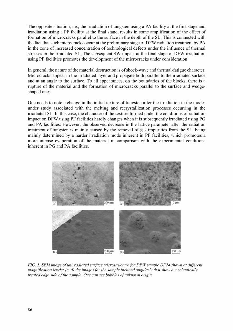
86
The opposite situation, i.e., the irradiation of tungsten using a PA facility at the first stage and irradiation using a PF facility at the final stage, results in some amplification of the effect of formation of microcracks parallel to the surface in the depth of the SL. This is connected with the fact that such microcracks occur at the preliminary stage of DFW radiation treatment by PA in the zone of increased concentration of technological defects under the influence of thermal stresses in the irradiated SL. The subsequent SW impact at the final stage of DFW irradiation using PF facilities promotes the development of the microcracks under consideration.
In general, the nature of the material destruction is of shock-wave and thermal-fatigue character. Microcracks appear in the irradiated layer and propagate both parallel to the irradiated surface and at an angle to the surface. To all appearances, on the boundaries of the blocks, there is a rupture of the material and the formation of microcracks parallel to the surface and wedge-shaped ones.
One needs to note a change in the initial texture of tungsten after the irradiation in the modes under study associated with the melting and recrystallization processes occurring in the irradiated SL. In this case, the character of the texture formed under the conditions of radiation impact on DFW using PF facilities hardly changes when it is subsequently irradiated using PG and PA facilities. However, the observed decrease in the lattice parameter after the radiation treatment of tungsten is mainly caused by the removal of gas impurities from the SL, being mainly determined by a harder irradiation mode inherent in PF facilities, which promotes a more intense evaporation of the material in comparison with the experimental conditions inherent in PG and PA facilities.
FIG. 1. SEM image of unirradiated surface microstructure for DFW sample DF24 shown at different magnification levels; (c, d) the images for the sample inclined angularly that show a mechanically treated edge side of the sample. One can see bubbles of unknown origin.

87
FIG. 2. Surface areas of the polished edge metallographic section for unirradiated DFW sample DF24. One can see pores and rolling laps present in the surface layer.
FIG. 3. (a, b) SEM image of the irradiated surface; (c, d) the character of damage in the edge metallographic section of DFW sample DF34 irradiated using a PF-6 plasma focus facility (32 pulses).
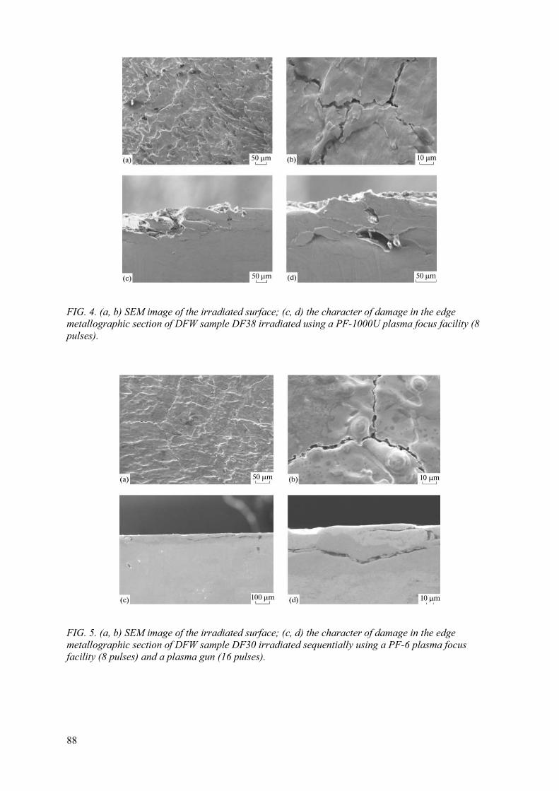
88
FIG. 4. (a, b) SEM image of the irradiated surface; (c, d) the character of damage in the edge metallographic section of DFW sample DF38 irradiated using a PF-1000U plasma focus facility (8 pulses).
FIG. 5. (a, b) SEM image of the irradiated surface; (c, d) the character of damage in the edge metallographic section of DFW sample DF30 irradiated sequentially using a PF-6 plasma focus facility (8 pulses) and a plasma gun (16 pulses).

89
FIG. 6. (a, b) SEM image of the irradiated surface; (c, d) the character of damage in the edge metallographic section of DFW sample DF-33 irradiated sequentially using a PF-6 plasma focus facility (16 pulses) and a plasma gun (32 pulses). The asterisks in (d) mark the impact zone depth amounting to 150 μm.
FIG. 7. (a, b) SEM image of the irradiated surface; (c, d) the character of damage in the edge metallographic section (c, d) of DFW sample DF36 irradiated sequentially using a PF-1000U plasma focus facility (2 pulses) and a plasma gun (250 pulses).

90
FIG. 8. (a, b) SEM image of the irradiated surface; (c, d) the character of damage in the edge metallographic section (c, d) of sample DF15 irradiated sequentially using a PF-6 plasma focus facility (4 pulses) and a QSPA Kh-50 plasma accelerator (10 pulses).
FIG. 9. SEM image of the irradiated surface of DFW sample DF15 after irradiation using only a PF-6 plasma focus facility (4 pulses).

91
FIG. 10. (a, b) SEM image of the irradiated surface; (c, d) the character of damage in the edge metallographic section of DFW sample DF40 irradiated sequentially using a PF-1000U plasma focus facility (4 pulses) and a QSPA Kh-50 plasma accelerator (10 pulses).
FIG. 11. (a, b) SEM image of the irradiated surface; (c, d) the character of damage in the edge metallographic section of DFW sample DF21 irradiated sequentially using a QSPA Kh-50 plasma accelerator (10 pulses) and a PF-6 plasma focus facility (10 pulses).

92
FIG. 12. (a, b) SEM image of the irradiated surface; (c, d) the character of damage in the edge metallographic section (c, d) of DFW sample DF73 irradiated sequentially using a QSPA Kh-50 plasma accelerator (10 pulses) and a PF-6 plasma focus facility (5 pulses).
REFERENCES
[1] HIRAI, T., PANAYOTIS, S., BARABASH, V., AMZALLAG, C., ESCOURBIAC, F., DUROCHER, A., MEROLA, M., LINKE, J., LOEWENHOFF, TH., PINTSUK, G., WIRTZ, M., UYTDENHOUWEN, I., Use of tungsten material for the ITER divertor, Nucl. Mater. Energy 9 (2016) 616–622.
[2] PINTSUK, G., Tungsten as a plasma-facing material, in Comprehensive Nuclear Materials, Elsevier (2012) 551–581.
[3] PITTS, R.A., CARPENTIER, S., ESCOURBIAC, F., et al., Physics basis and design of the ITER plasma-facing components, J. Nucl. Mater. 415 (2011) S957–S964.
[4] GARKUSHA, I.E., LANDMAN, I., LINKE, J., MAKHLAJ, V.A., MEDVEDEV, A.V., et al., Performance of deformed tungsten under ELM-like plasma exposures in QSPA Kh-50, J. Nucl. Mater. 415 (2011) 65–69.
[5] ANKUDINOV, A.V., VORONIN, A.V., GUSEV, V.K., GERASIMENKO, YA.A., DEMINA, E.V., PRUSAKOVA, M.D., SUD’ENKOV, YU.V., Influence of a plasma jet on different types of tungsten, Tech. Phys. 59 (2014) 346–352.
[6] WIRTZ, M., LINKE, J., PINTSUK, G., RAPP, J., WRIGHT, G., Influence of high flux hydrogen-plasma exposure on the thermal shock induced crack formalism in tungsten, J. Nucl. Mater. 420 (2012) 218–221.
[7] GRIBKOV, V.A., Physical processes taking place in dense plasma focus devices at the interaction of hot plasma and fast ion streams with materials under test, Plasma Phys. Controlled Fusion 57 (2015) 065010.
[8] PIMENOV, V.N., DEMINA, E.V., IVANOV, L.I., et al., Damage and modification of materials produced by pulsed ion and plasma streams in Dense Plasma Focus device, Nukleonika 53 (2008) 111–121.
[9] VORONIN, A.V., ALEKSANDROV, A.E., BER, B., et al., Experimental study of cyclic action of plasma on tungsten, Tech. Phys. 61 (2016) 370–376.

93
[10] VILÉMOVÁ, M., PALA, Z., JÄGER, A., et al., Evaluation of surface, microstructure and phase modifications on various tungsten grades induced by pulsed plasma loading, Phys. Scr. 91 (2016) 034003.
[11] SHENG, H., SUN, Z., UYTDENHOUWEN, I., VAN OOST, G., VLEUGELS, J., Temperature and deformation effect on the low and high angle grain boundary structure of a double forged pure tungsten, Int. J. Refract. Met. Hard Mater. 50 (2015) 184–190.
[12] MAKHLAI, V.A., GARKUSHA, I.E., LINKE, J., et al., Damaging of tungsten and tungsten–tantalum alloy exposed in ITER ELM-like conditions, Nuclear Materials and Energy 9 (2016) 116–122.
[13] LEMAHIEU, N., LINKE, J., PINTSUK, G., VAN OOST, G., WIRTZ, M., ZHOU, Z., Performance of yttrium doped tungsten under ’edge localized mode’-like loading conditions, Phys. Scr. 159 (2014) 014035.
[14] SHIROKOVA, V., LAAS, T., AINSAAR, A., et al., Comparison of damages in tungsten and tungsten doped with lanthanum- oxide exposed to dense deuterium plasma shots, J. Nucl. Mater. 453 (2013) 181–188.
[15] WIRTZ, M., LINKE, J., PINTSUK, G., SINGHEISER, L., AND ZLOBINSKI, M., Comparison of thermal shock damages induced by different simulation methods on tungsten, J. Nucl. Mater. 438 (2013) S833–S836.
[16] LATYSHEV, S.V., GRIBKOV, V.A., MASLYAEV, S.A., PIMENOV, V.N., PADUCH, M., ZIELINSKA, E., Generation of shock waves in materials science experiments with dense plasma focus device, Inorg. Mater.: Appl. Res. 6 (2015) 91–95.
[17] MOROZOV, E.V., MASLYAEV, S.A., PIMENOV, V.N., et al., Evolution of tungsten surface affected by powerful energy fluxes, Perspekt. Mater. 10 (2015) 32–45.
[18] VALI, B., LAAS, T., PAJU, J., SHIROKOVA, V., PADUCH, M., GRIBKOV, V.A., DEMINA, E.V., PIMENOV, V.N., MAKHLAI, V.A., ANTONOV, M., The experimental and theoretical investigations of damage development and distribution in double-forget tungsten under plasma irradiation-initiated extreme heat loads, Nukleonika 61 (2016)169–177.
[19] MOROZOV, E.V., DEMIN, A.S., PIMENOV, V.N., et al., Features of the damage and the structural changes in the tungsten surface layer under the pulsed action of laser radiation, ion, and plasma fluxes, Inorg. Mater.: Appl. Res. 9 (2018) 361–369.
[20] BUDAEV, V.P., MARTYNENKO, YU.V., KARPOV, A.V., et al., Tungsten recrystallization and cracking under ITER relevant heat loads, Vopr. At. Nauki Tekh., Ser.: Termoyad. Sint. 36 (2013) 53–60.
[21] VORONIN, A.V., SEMENOV, B.N., AND SUD’ENKOV, YU.V., Mechanism of tungsten destruction under thermal load and a plasma jet, Vestn. S.-Peterb. Univ., Ser. 1: Mat., Mekh., Astron. 2 (2015) 106–111.
[22] GARKUSHA, I.E., MALYKHIN, S.V., MAKHLAI, V.A., PUGACHEV, A.T., BAZDYRIEVA, S.V., AKSENOV, N.N., Changes in the structure and substructure of tungsten during irradiation by hydrogen plasma flows at the specific energy close to the heat loads on the ITER surface, Tech. Phys. 59 (2014) 1620–1625.
A
B
C
94
ANALYTICAL AND THEORETICAL INVESTIGATIONS OF EFFECTS PRODUCED BY HOT PLASMA AND FAST ION/ELECTRON BEAMS AT IRRADIATIONS OF MATERIALS E.V. DEMINA*, V.A. GRIBKOV*,**, V.N. PIMENOV* * A.A. Baikov Institute of Metallurgy and Material Science, Russian Academy of Sciences,
Moscow, Russian Federation Email: [email protected]
** The Institute of Plasma Physics and Laser Microfusion,
The International Centre for Dense Magnetized Plasmas, Warsaw, Poland
1. INTRODUCTION
Currently it is shown that stationary operation of promising thermonuclear systems can be provided with a use of a so-called "lithium technology" [1]. Liquid lithium held by capillary forces within the porous matrix of steel, tungsten or other materials perceives high energy loads coming on elements of tokamak constructions (first wall, divertor, limiter), and simultaneously improves the performance plasma discharge, preventing entry into its heavy impurities. As confirmed experimentally [2,3], the use of Capillary Porous Systems (CPS) with Liquid Lithium is a promising alternative to traditional construction materials when creating a plasma-contacting intra-cameral element of stationary fusion reactors. The most important requirements for the materials of these elements are a high degree of their resistance to erosion, as well as the stability of the structure and properties with pulsed exposure to powerful plasma flows. The characteristic parameters of plasma exposures expected in tokamak reactor are given in Table 1 [4]. The advantage of CPS with lithium compared to traditional construction materials is its high resistance to destruction due to thermal expansion compared to compact solid materials [3]. According to the estimations for this type of CPS manufactured from refractive materials maximum thermal power flux density to the surface, not leading to its destruction, can reach 100 MW/m2 [5,6], which is much higher than the values for any compact metal. In addition, the local destruction of the fibres does not lead to the destruction of the CRP as a whole and does not violate its functional qualities. Porous systems with liquid lithium are also more resistant to radiation exposure and swelling [7].
High relaxation ability fibrous CPS virtually eliminates the problems of compatibility with them in contact with other structural elements (there are no mechanical stresses at the interface of materials).
The ability of the CPS to form, continuously maintain and renew the protective film of liquid lithium on the surfaces of various shapes and orientation in space, to stabilize it when exposed to external forces because of the capillary effect leads to the fact that the plasma interacts only with liquid lithium and does not affect the basis of the CPS. In turn, lithium protects the design of intra-chamber elements by evaporation and does not contaminate plasma.
The purposes of this work are:
To study the durability of lithium CPS under the influence of high-energy flows of deuterium plasma;

95
Experimental verification of the stability of tungsten lithium CPS after interaction with atmospheric gases, subjected to the effects of extreme high thermal plasma flows.
2. EXPERIMENTAL STUDY OF PERSISTENCE OF LITHIUM CPS
Stainless steel, molybdenum and tungsten meshes (mesh mats) were used as materials of the basis of the CPS matrix. The meshes were soaked by lithium. The appearance of the CPS in the initial state is presented in Fig. 1. The effective radius of the capillary pores reff of the mesh mats were varied in limits 15–200 microns. Diameter of wire used in the CPS ranged 30–200 microns. Lithium impregnated targets were 1–2 mm thick. The design of the target also included a heater to establish the initial temperature in the range 20–350 °C. Temperature was controlled by a thermocouple.
Simulation of the processes of irradiation of the surface of the construction materials by high-energy plasma fluxes were carried out at the accelerator of deuterium plasma KSPU and MK-200U (TRINITY, Moscow) and at the experimental stand of A.F. Ioffe PTI (St.-Petersburg). Their operating parameters are given in Table 2. It can be seen that impacts of plasma disruption instability and its various disturbances (Table 1) upon materials are sufficiently modelled on these installations.
ТABLE 1. PARAMETERS OF PLASMA EFFECT ON DEMO REACTOR MATERIALS
Impact Specific heat flux, MW/m² duration of exposure, s Regular plasma discharge 0.5–10 7200 Peak load 20 10 Thermal failure 33000 1.5×10⁻³ Plasma disturbances 250–500 1×10⁻³
In all cases, the deuterium plasma flow interacted with the surface of the same type targets. The study of the interaction process of plasma streams with surfaces of targets made by steel and molybdenum was carried out on plasma accelerators XSP and MK200UG by the methods of optical X ray spectroscopy, laser interferometry and laser scattering, Langmuir probes and optic bolometer of the type BMC-3.
TABLE 2. MODEL EXPERIMENT CONDITIONS
Parameter KSPU MK-200U Joffe PTI stand Specific energy flow, Q, MJ/m2 4–5 15 0.25–0.43 Discharge duration, t, s 5×10⁻⁴ 4×10⁻⁵ 1.5×10⁻⁵ Plasma density, ne, cm–3 (2–5)×1016 (2–5)1015 n/a Specific power of plasma flow, P, GW/m2 10 400 22–41 Number of pulses per target 22 17 100
Structural surface state of the target material after plasma exposure was examined by optical (NEOPHOT-32) and scanning electron (EVO 40 (Zeiss)) microscopy. In addition, the quantitative estimation of erosion processes was performed by a gravimetry method (GNU-KS). For experiments at the PTI stand, samples of a special-purpose tungsten grid impregnated with lithium were used (Fig. 1(c)). Impact area of plasma action upon the sample was provided by a mask made from a tungsten plate with a hole of 10 mm in diameter. First, the sample was

96
heated with a halogen lamp up to 200 °C. After 100 μs next to the start of irradiation, the surface temperature was measured using an original two-colour pyrometer, developed at the A.F. Ioffe PTI, with integration time ~ 10 µs. The samples irradiated in this way were examined by scanning electron microscopy using the setup LEO 430 i with an OXFORD Link for local X ray spectral analysis, and by X ray diffraction analysis using a Rugaky (XRD) Ultima-IV diffractometer (Japan).
As a result of studies of lithium CPS samples irradiated at plasma accelerators KSPU and MK200UG, it was established [5–9] that two processes occur on the surface of the targets: drop erosion of liquid lithium and formation of dense near-surface vapor layer.
It was shown (Fig. 2) that during the first 10 μs after the start of exposure of the target to plasma flow in a QSPA (quasi-stationary plasma accelerator) at the target (lithium CPS) surface a dense (n ~ 1017 cm–3) emitting layer of neutral lithium with a thickness of ~ 10 mm is formed, which by the end of the pulse increases to 40 - 50 mm. Formation of such the protective layer leads to a radical decrease in the flow of energy reaching the surface of the target Qsurf relative to the incident flow plasma Qpl: Qsurf ~ 0.01 Qpl. In the study using atomic emission spectroscopy with installation of the type of MGA-915 AD spectral lines of the CPS base materials (Fe, Cr, Ni) in the experiments were not found.
A similar picture was observed in [10] on Pilot-PSI, with a CPS W-Sn target, when during plasma irradiation was also not detected spectral lines of the CPS base material (W). It is a characteristic feature that in all cases some periodic fluctuations in the density of vapor of low-melting material and target surface temperature occur.
Gravimetric research results (Fig. 3) showed the ability of CPS to inhibit significantly the erosion of liquid lithium compared to erosion of free surface. For comparison specific mass loss Δm/S2 of free lithium for one pulse of plasma exposure at Q = 10 GW/m2 was 50…150 mg/cm2, and for lithium CPS – 1…12 mg/cm2. Moreover, the value of the specific loss is proportional to the radius of the pores of the CPS. Important factor affecting the amount of erosion of liquid metal, is the angle α of the flow coming to the surface of the CPS target. With increasing of the angle, the rate of erosion increases significantly. As shown by the results of laser scattering, the liquid metal eroded in the form of droplets, scattered mainly in the target plane. The size of the droplets did not exceed 1 mm, and their speed was 0.1…10 m/s.
Erosion of lithium from the CPS surface, depending on the initial phase state of lithium, is presented in Fig. 4. If lithium was in liquid condition (250 °C), the magnitude of the erosion does not depend on the number of plasma irradiation pulses. If lithium was in a solid initial state (20 °C), then the amount of erosion increased with the number of pulses, which led to the formation of wavy profile on the surface of the target that is characteristic for all solid metals.
From a series of experiments on lithium CPS samples with different values of wire diameter (d) and pore size (reff) the limit of the resistance to erosion damage with the certain “critical” values of these parameters was set.
When d > 200 μm and reff > 150 μm the surface of the CPS steel wires after 100 pulses of high-temperature plasma showed traces of melting, which indicated the absence of wetting them with lithium and an increase in temperature of their surface up to more than 1500 °С (Fig. 5b). After a similar exposure of the samples, having a reff < 15 μm, the effect of “draining” the surface of the metal wire was not observed, and signs of violations of the basis of the CPS completely

97
absent (Fig. 5(a)). Important role in doing so is played by the lack of oxidation of the surface of the original CPS.
It needs to be noted that the basic material of the CPS, not filled with lithium, subjected to complete destruction when exposed to a single pulse of plasma. An important aspect of the study was determination of the influence of products of lithium reaction with atmospheric gases and water vapor for the performance of materials based on CPS with lithium, since such an impact can occur during the operation of liquid metal devices based on lithium CPS, and in technological processes of their preparation for work. In experiments with a pure lithium surface or with targets, where the layer of reaction products of lithium with an atmosphere of no more than 10 microns, the presence of these surface layers had no effect on the behavior of CPS when learning in a plasma vapor. After the very first impact pulse, the CPS surface acquired a metallic sheen, i.e. the reaction products were easily removed.
On the other hand, the behavior of highly oxidized lithium CPS (being about 10 hours under normal conditions of temperature and pressure) was investigated in a series of experiments on the stand in the A.F. Ioffe PTI. The thickness of the reaction products in the virgin surface layer in these samples could exceed 300 microns. Results of plasma exposure of samples with surface, pre-interacting with the atmosphere (Fig. 6), significantly differ from the result of samples with a clean surface (when lithium did not interact with atmospheric gases, Fig. 1). In Fig. 6, the melted elements of the CPS base (tungsten wire), the traces of melting and the cracks of the lithium impregnation are visible. Measurement of the target surface temperature (Fig. 7) and the melting of the W wire (Fig. 6) indicate that the surface temperature exceeded 3380 °C. In addition, there was a degradation of thermal conductivity of the CPS with an increase in the number of pulses of plasma exposure, which was expressed in a progressive decrease in a speed of cooling of the target after pulse. The study of the surface of samples by X ray diffractometry (Fig. 8) after 100 pulses showed the presence of reaction products of lithium with atmospheric gases (Li2CO3, LiOH) and of tungsten.
3. DISCUSSION OF THE RESULTS
Based on the results, one can state that the CRP with lithium as a material of the intra-chamber tokamak elements has higher resistance to impact of transitional processes in plasma with reactor parameters compared to solid structural materials. The presence of the CPS reduces the rate of erosion of the surface by tens of times and ensures its constant updating due to capillary forces. Lithium retention by the CPS surface, based on the equation of balance of forces, is described by the expression:
2 cos,EM pl ev
eff
T QP P P
r
(1)
where σ (T) is the surface tension coefficient, Q – wetting angle, PEM — pressure pulse in liquid metal, generated by electromagnetic forces, Ppl – plasma pressure, Pev – pressure of vapours of liquid metal. Taking into consideration mechanisms acting at the conditions realized on the tokamak surfaces, such as “bubble boiling”, "wind waves" and the instability of the liquid surface of the type of Kelvin-Helmholtz it is possible to suggest that the capillary effect in the CPS effectively suppresses the last two mechanisms. It is so in particular especially at angles of the plasma stream incidence other than zero when these mechanisms are major. The critical parameter in this case will be the effective pore size of the CPS reff = rcrit, when the inequality (1) still holds. In that case, the mass loss of the liquid metal will be less compared with some

98
critical value, which prevents a violation of heat sink and overheating of the constructions to a temperature above the melting point. In this case, the CPS will not be destroyed.
Under the conditions of the considered experiments the critical value was the radius reff ~ 150 µ. With reff < rcrit, the “bubble boiling” is the main mechanism of erosion. In this case, the loss of heat dissipation in the outer layer of the CPS can be achieved under the condition when the diameter of the wire of the matrix of CPS will be greater than the thickness h of the erosion layer, the value of which is determined by the equation [3]:
1/2
1/2
~ ,
melt bp
pl
kT Pt
Ch
Q
(2)
where k is the Boltzmann constant, Cp is the heat capacity of the CPS, P is the vapor pressure of the liquid metal, tb is the duration of the plasma exposure process, Tmelt – the melting point of the base (matrix) material of CPS, Qpl – heat flux from plasma.
From here it follows that the critical parameter for the CPS is also the diameter dcrit = h. For CPS based on stainless steel the critical value was a wire diameter d ~ 200 µm, which is in good agreement with the critical value estimated from equation (2). For more refractory metals the critical value of d increases substantially.
The most important factor providing the stability of the CPS is the formation of a near-surface radiating layer of liquid metal vapor. When a lithium surface is heated, a dense layer of vapor is formed, in which the energy of the particles is efficiently reemitted due to the excitation of lithium atoms. Based on the analysis of the balance of heat flows, it was found that only 1% of the energy flux from the plasma reaches the surface, and 99% is dissipated by radiation. Reduction flow to the surface leads to a drop in temperature and, as a consequence, to a decrease in the thickness and density of the vapor layer. So, the proportion of plasma energy reaching the surface increases again. The cycle is repeated. This effect may explain observed in Fig. 2 cyclic change of vapor density above the target surface during irradiation.
The absence or strong limitation of evaporation prevents the formation of a protective layer in the case of a highly oxidized surface of the target, which is probably the reason for the experimentally observed significant heating of the surface up to the melting of the CPS base metal with tungsten. The low thermal conductivity of lithium compounds causes high temperature gradients in the structure of the surface layers of the oxidized CPS, and, consequently, high thermal stresses. Taking into consideration the fragility of lithium products, it can be assumed that progressing with increasing number of pulses the cracking and destruction of the layer (oxidized over the depth) is reflected in a decrease in its thermal conductivity and, as a consequence, in an increase in the cooling time of the surface after exposure to plasma.
4. CONCLUSIONS
High resistance of lithium CPS to erosion damage when exposed to plasma flows with high specific energy density of the order of hundreds of GW/m2, is provided by suppressing the mechanisms of droplet ablation by capillary forces and by the formation of a near-surface radiating layer of liquid metal vapor. The ability of the CPS to restore the liquid surface of lithium due to capillary forces and the high temperature resistance of the fibrous structure of

99
the CPS base ensure high stability of the properties and the absence of degradation of this material. It has been experimentally shown that significant thickness (more than 10 microns) layers of lithium reaction products with residual gases can significantly reduce the resistance of CPS to exposure to plasma flows. The technology of the lithium CPS usage needs to not allow situations contributing to the formation of the above-mentioned specified products.
a b
c
FIG. 1. The surface of CPS with lithium. (a) Stainless steel mesh with reff = 15 µm; (b) molybdenum mesh with reff = 75 µm; (c) mesh from tungsten with reff = 25 µm.

100
FIG. 2. Space-time distribution of lithium vapor density at the target surface [6].
FIG. 3. Dependence of lithium erosion on the radius of CPS pores at different angles α of the flux drop on the target: 1 — α = 45°; 2 — α = 0°. The initial target temperature is 350 °C. Q = 10 GW/m2 [1, 2].
0
2
4
6
8
101
2
m, mg/cm2
R meff,50 1 00 1 05

101
FIG. 4. (a) Laser interferogram of the emission of lithium droplets from the surface of the CPS (reff = 75 µm) at 20 °C; (b) at 250 °C [4, 5].
FIG. 5. (a) Surface of the СPS based on 18/8 type steel reff = 15 μm ; d = 30 μm; (b) reff = 150 μm; d = 200 μm [1, 2].
(a)
(a) (b)
(b)

102
FIG. 6. Surface of W – Li СPS sample after 100 pulses of deuterium plasma with a power of 22 GW/m2. Tungsten wire fragments (1) and oxidation products (2) are visible.
FIG. 7. Evolution of the temperature of a СPS surface during and after plasma action: 1–7, 2–29, 3–52, 4–70 pulses respectively.

103
FIG. 8. X ray diffraction pattern of the W – Li surface of CPS after 100 pulses of the plasma flow at 22 GW/m2.
REFERENCE
[1] VELIKHOV YE.P., KOVALCHUK M.V., ILGISONIS V.I., IGNATYEV V.V., TSIBULSKY V.F., ANDRIANOVA YE.A., BLANDINSKY V.YU., Yadernaya energeticheskaya sistema s reaktorami deleniya i sinteza – strategichesky oriyentir razvitiya otrasli. Voprosy Atomnoy Nauki i Tekhniki (VANT), Ser. Termoyaderny Sintez., Problems of Atomic Science and Engineering, Ser. Thermonuclear Fusion 40 (2017) 5–13.
[2] NYGREN R.E., TABARÉS F.L., Liquid surfaces for fusion plasma facing components – A critical review, Part I: Physics and PSI, Nuclear Materials and Energy 9 (2016) 6–21.
[3] MIKHAILOV V.N., EVTIKHIN V.A., VERTKOV A.V., CHUMANOV A.N., Lithium in thermonuclear and space energy of the XXI century, Energoatomizdat (1999) 528.
[4] FEDERICI G., KEMP R., WARD D., HARMAN J. et al., Overview of EU DEMO design and R&D activities, Fusion Eng. Des. 89 (2014) 882–889.
[5] ANTONOV N., BELAN V., EVTIKHIN V. et al., Experimental and calculated basis of lithium capillary system as divertor, J. Nucl. Mater. 241–243 (1997) 1190–1196.
[6] EVTIKHIN V.A., LYUBLINSKI I.E., VERTKOV A.V., BELAN V.G., KONKASHBAEV I.K., NIKANDROV L.B., Calculation and experimental investigation of fusion reactor divertor plate and first wall protection by capillary-pore systems with lithium, J. Nucl. Mater. 271–272 (1999) 396–400.

104
[7] IVANOV L.I., KROKHIN O.N., NIKULIN V.YA., POLUKHIN S.N., TIKHOMIROV A.A., EVTIKHIN V.A., LYUBLINSKI I.E., VERTKOV A.V., Investigation of the pulse plasma stream influence on the lithium capillary-porous system, Int. J. of Nuclear Research, Nukleonika 46 (2001) S113–S115.
[8] EVTIKHIN V. A., LYUBLINSKI I.E., VERTKOV A.V., MIRNOV S.V., SOTNIKOV S.M., PROKHOROV A.S., AZIZOV E.A., LAZAREV V.B., SAFRONOV V.M., KOZHAVIN V.M., Main direction and recent test model in Science and Technology 6 (2004) 2291–295.
[9] LYUBLINSKI I.E., VERTKOV A.V., EVTIKHIN V.A., Application of practical use of lithium in experimental facilities and fusion devices, Plasma Devices and Operations 17 (2009) 265 – 285.
[10] VAN EDEN S., VAN DE SANDEN M.C.M., MORGAN T., Oscillatory vapour shielding of liquid metal walls in nuclear fusion devices, Nature Communications 8 (2017).

105
IRRADIATION, CHARACTERIZATION, AND MODELLING OF NEW ADVANCED MATERIALS FOR INERTIAL FUSION ENERGY R. GONZALEZ-ARRABAL, A. RIVERA, O. PEÑA-RODRIGUEZ, M. PANIZO-LAIZ, P. DIAZ-RODRIGUEZ, A. FIERRO, J. M. PERLADO Instituto de Fusión Nuclear “Guillermo Velarde”, Universidad Politécnica de Madrid, Madrid, Spain Email: [email protected] Abstract
This research was carried out in order to contribute to predict, to understand and to solve some of the bottle necks for fusion to become a reality. The most part of the work was devoted to the development of materials with improved properties to be used for plasma facing application, permeation and corrosion barriers. Focusing on Plasma Facing Materials (PFM) we have modelled the thermomechanical behaviour of the tungsten First Wall (FW) in the three foreseen HiPER laser fusion scenarios (Experimental, Prototype and Demo). We have identified that the lifetime of the FW is limited by fatigue loading and we have estimated it for the different scenarios. Moreover, we have calculated the minimum thickness of a W FW to fulfil its protection task. We have also studied the role of grain boundaries on the radiation-induced damage and on the light species in W. We have studied the thermal stability of nanostructured W by carrying out isothermal annealing and by subjecting the samples to large thermal loads in a plasma focus facility. Finally, we have analysed the capabilities of the ESS-Bilbao (Spanish ion/neutron source inside the frame of the European Spallation Source system in Lund) facility to study the materials behavior under thermal loads in the presence of ions simultaneously. We conclude that this facility is suitable to test PFM under inertial fusion conditions. Concerning the development of permeation barriers, we have studied the influence of the sputtering parameters and of the surface finishing of the substrate on the adhesion of SiC coatings to Ni substrates. We have performed permeation experiments on homogeneous and SiC coatings well adhered to the substrates, finding out a PRF value lower than that previously reported for coatings deposited on steel. Regarding the development of corrosion protection coatings, we have studied two different materials: SiC and nanostructured W. For this purpose, coatings were deposited on EUROFER substrate. We have optimized the adhesion of the coatings to the substrate. So far, accelerated corrosion tests indicate that nanostructured W coating may work as a suitable corrosion protection layer at temperatures in the range 350–550ºC. We have also worked on rector technology. In this subject we have developed a conceptual design of HiPER final lenses and of a ceramic breeding blanket with tritium breeding ratio tuning capabilities. By combining experiments and computer simulations, we have studied the different processes involved in the permanent modification of silica formed by ion-induced high electronic excitation. Results allows us defining the threshold energy density for track formation and describe the different processes which leads to permanent modification. The proposed model can be used to described ion-induced modifications in different materials. We have studied the capabilities of the ESS-Bilbao to study of materials neutron irradiation under nuclear fusion conditions, focusing on structural, silica-based optical and ceramics materials as well as, on electronic components. We have also analysed the use of lasers for neutron production.
1. INTRODUCTION
The development of materials able to withstand the severe reactor environment (large radiation fluxes and thermal loads) is one of the main challenges to make fusion energy a reality. Nowadays, a lot of efforts are being carried out to develop materials with improved properties able to withstand the harsh conditions taking place in these reactors. In particular, as described in detail bellow, to move towards the construction of an inertial fusion reactor is important to develop: (i) plasma facing materials able to promote the outgassing of light species such as He

106
and H to delay the appearance of blistering and exfoliation; (ii) tritium permeation barriers to avoid the tritium permeation through structural materials; and (iii) corrosion resistant materials compatible with lithium-lead eutectic alloy or pure lithium at high temperatures, among others. For the development of these materials is important to combine experiments with computer simulations which allows us to understand so much from the fundamental point of view the phenomena that occur in the materials under the predicted working conditions as well as, to predict their behavior. Moreover, the combination of experiments and computer simulation also contribute to define operational windows.
Another important task when talking about materials for inertial confinement nuclear fusion applications is their qualification. Because of that different facilities have been build all around the world to mimic real operation conditions and to test materials. As an example, different facilities have been constructed to perform lithium and lithium lead corrosion test [1,2]. However, the qualification of plasma facing materials (PFM) in inertial fusion is stills a matter of concern. It is already known that the materials damage induced by synergistic effect (simultaneous ion irradiation, He+H, C+He+H, and/or simultaneous ion irradiation plus thermal loads notably differ from those originated in the material when subjected to sequential threats e.g. first He and then H [3]. On this basis the magnetic fusion community has developed different facilities to test PFM under realistic operation conditions to account for the synergistic effects [4]. However, because of the different in ion energy (eV range when talking about magnetic fusion and MeV when talking in inertial fusion), neither the facilities built for the qualification of PFM by the magnetic fusion community can be used for the qualification of PFM by the inertial fusion community, nor the results obtained from these tests can be extrapolated to predict the damage originated in the materials when irradiated under inertial fusion conditions. Therefore, the search for new facilities able to simulate the synergistic effects that the PFM of an inertial fusion reactor have to withstand is crucial in the search and development of new materials. For this reason, in the framework of this CRP, we have studied the possibility of using the ESS-Bilbao for this purpose.
2. REACTOR TECHNOLOGIES
2.1. Conceptual design of HiPER final lenses
We have studied the performance of silica final lenses in laser fusion facilities under realistic irradiation conditions for HiPER and LIFE2 [5]. We have calculated the radiation fluxes, the radiation-induced temperature enhancement, stress generation and the formation of colour centres. We have evaluated the thermo-mechanical and optical behavior. We have also studied the evolution of colour centres during reactor start up. From these data we have concluded that for a proper work, ions need to be mitigated. We have analysed how ion mitigation could be introduced using electrostatic and magnetic fields [6].
Even when assuming that ions are mitigated, in the present reactor configuration neutrons are going to reach the final lenses. We have studied how the neutron irradiation promotes the creation of colour centres that absorb laser and promotes aberration which leads to defocussing.
We have estimated how the colour centres can be annealed out at high temperatures [13]. On these bases, we have developed a temperature control system that allows keeping the lenses at temperatures high enough to favour colour centre annealing [7]. The temperature control system is based on a heat-transfer fluid which allows keeping constant the temperature during the whole operation of the reactor, even during the start-up. This system allows us to keep a good

107
illumination uniformity (σ<1%) and a high efficiency (η~90%) by adjusting the fluid temperature. We have studied the performance of several fluids and CO2 is the best solution.
Finally, we have determined the minimum distance that needs to be kept between the final lenses and the target for a proper performance in the different HiPER scenarios. It is 8 m for the experimental facility and ~16 m for a full-scale reactor (DEMO) [6].
The main limitations of the proposed solution are the requirement of high temperature operation (>800 K) and the necessity to place the lenses at 16 m from the target, which results in large facility dimensions. Other solutions could overcome these limitations at the cost of introducing other potential problems.
2.2. Conceptual design of a ceramic breeding blanket with tritium breeding ratio tuning capabilities
Blanket concepts rely on designs that do not make possible to modify the tritium breeding ratio (TBR), despite the authors of such designs admit that the calculated TBR is prone to uncertainties and that unavoidably TBR will change over time during operation. In other words, concept designs of blanket rarely consider correction procedures to modify the TBR. Regarding dynamic ways to modify TBR during operation, to the best of our knowledge there is only one paper reporting the use of liquid blankets with different enrichment [8]. We have developed a concept design that addresses this question. It is based on lithium ceramics and it allows operators to easily change the TBR during operation from a tritium production that leads to an inventory with tritium deficit to a high tritium production that leads to an inventory with excess tritium. This flexibility will make possible to compensate uncertainties in the design, natural changes during operation and to keep a good tritium inventory [9].
3. PLASMA FACING MATERIALS
3.1. Modelling the thermomechanical behavior of the tungsten first wall in HiPER laser fusion scenarios
We have studied the behavior of a tungsten first wall under the irradiation conditions foreseen for the three different operational scenarios of the European laser fusion project HiPER. The scenarios correspond to different stages in the development of a nuclear fusion reactor (Experimental, Prototype and Demo). Results have been published in Ref. [10].
In this publication, firstly we have calculated the radiation fluxes assuming the geometrical configurations reported so far for HiPER. Then, by means of the finite element solver Code Aster, the irradiation-induced evolution of first wall temperature and the thermomechanical response of the material were calculated. The system used for the calculations assumes that the irradiation pulse reaches the chamber, which is protected by a W FW. Heat is transferred through the substrate to the substrate/coolant interface. The heat is finally removed by the LiPb coolant (for HIPER Prototype and Demo) or by the borated concrete shielding (for HIPER Experimental). The FW is made of pure W with a thickness of 1 mm. For pure W, isotropic behavior is implemented using the material properties reported in the ITER material handbook. The substrate is assumed to be an ODS-RAFM steel with a thickness of 1 cm. The coolant is supposed to be eutectic LiPb (Pb 17 at. %), working between 600-800 K. Moreover, for the calculations we have also implemented the temperature-dependent properties of the different materials.

108
Results indicate that the energy carried by X rays and ions is deposited in the first 100 μm of W during times of ~4 μs. During irradiation three temperature peaks appear, corresponding to pulses of X rays, burn ions and debris ions generated with every target implosion and ignition. As a result, the FW expands until the irradiation ceases and the material cools down, leading to a tensile state due to the appearance of a plastic region. The plastic region affects the first microns of the FW. Fatigue appears due to the cyclic nature of the irradiation and it limits the lifetime of the FW in the different HiPER scenarios. We found out that Experimental facility could operate with a W FW, thanks to the employed low energy targets and the limited demand of shots. However, in Demo, damage will appear in the FW limiting its lifetime to 28 hours. Here, we meet several problems: the peak temperature during each pulse is near the melting temperature, the energy fluence is above reported threshold damage values and cracks would appear and propagate shortly after the beginning of operation. Regarding the thickness of the W FW, the main limiting factor is crack propagation. We estimate that a W FW with a thickness of at least ~200 μm is required to fulfil its protection role.
3.2. Study of the capabilities and limitations of nanostructured W as Plasma Facing Material
3.2.1. Experimental and multiscale computer simulation studies of the influence of grain boundaries on radiation-induced damage and on hydrogen behaviour in W
Due to its properties tungsten is considered nowadays the best candidate for Plasma Facing Materials (PFM) applications, in both magnetic and inertial “confinement nuclear fusion reactors. However, some difficulties have been identified in coarse grained W (CGW) which have to be overcome” [11]. One of the main problems is related to the light species retention. Light species in CGW tend to nucleate in defects resulting in detrimental effects, unacceptable for a PFM. In this context, the development of new materials is needed.
In the last years, we focused our attention on the study of the capabilities and limitations of nanostructured W as PFM. For this purpose, we carried out different experiments and multiscale computer simulations (OKMC, DFT) to find out the role of grain boundaries (GBs) on the H behaviour [1,12,13,14]. Recently, we went a step further correlating radiation-induced damage and H behaviour on nanostructured samples [15]. For this purpose, we study the H behaviour at room temperature in three diversities of tungsten with different GB densities: nanostructured tungsten (NW), coarse-grained tungsten (CGW) and monocrystalline tungsten (MW), with no GBs at all. The experiments were performed in three set of samples each of them consisting of one NW sample with a columnar structure with an average diameter of ~100 nm [16] and a commercial CGW sample. A top view and a cross-sectional images of a typical nanostructured W sample is shown in Fig. 1. The first set of samples was implanted only with H. The second set was “sequentially implanted first with C and then with H. The third set was simultaneously implanted (co-implanted) with C and H. To mimic IC energies in HiPER, the implantation energies were selected to be 170 and 665 keV for H and for C, respectively. The implantation fluence, for both H and C, was 5×10²⁰ m-2” [11]. All implantations were performed at room temperature at the Helmholtz Zentrum Rossendorf Dresden (HZRD). The sample morphology and microstructure were characterized prior to and after implantation by high resolution scanning electron microscopy (FEG-SEM) and X ray diffraction (XRD), respectively. The H depth profiles were measured by resonance nuclear reaction analysis (RNRA) using the H(15N,He)12C nuclear reaction. RNRA measurements were carried out in HZRD. In order to account for experimental results, object kinetic Mont Carlo (OKMC) simulations were

109
performed by using the Open Source code MMonCa [17]. The parameterization is precisely described in Ref. 15.
From these results we conclude that at room temperature where the vacancies are immobile the vacancy density for nanostructured W is larger than for pure W. Thus, self-healing in W would happen at temperatures in which the mobility of Vs is activated. We also found that GBs behave as effective diffusion channels for H indeed, we observe that the H retained fraction for samples without GBs is very large, meaning that almost all implanted H atoms remain in the sample due to their low probability to reach the sample surface without being trapped by vacancies. Concerning to the location of H within the sample, we conclude that retained H atoms mostly remain in monovacancies located within the grains.
FIG. 1. Top view (a) and cross-sectional (b) images of a typical nanostructured W sample.
3.2.2. Prelaminar studies of the behaviour of nanostructured and coarse-grained tungsten under pulsed irradiation in a plasma focus device
When talking about Plasma Facing Materials, the other main concern is related to their capability to withstand large thermal loads. In particular, the knowledge of the thermal load resistant of the material in combination with its radiation-resistant would help to define proper operational windows.
In this CRP we have been closely collaborating with plasma group from the Comision Chilena de la Energía Nuclear leader by Prof. Soto to properly calculate the Heat flux parameter (H), delivered by a plasma focus. For this purpose, we have carried out different irradiation campaigns in Chile and Professor Soto has visited sometimes Madrid. Moreover, part of this work has been also oriented to the training of students. Indeed, a PhD from the IFN has spent three months in Chile to learn about the plasma focus science and technology.
Within this collaboration, we have investigated the behavior of nanostructured and coarse-grained tungsten under pulsed irradiation in a plasma focus device. These studies are very relevant in particular when dealing with nanostructured materials because of their metastability. We have studied the influence of the irradiation conditions (heat flux parameter and number of pulses) in the microstructure and light specie behavior. Currently, we are analysing obtained results.
Simultaneously, we have studied the thermal stability of NW coatings isothermally annealed in vacuum at temperatures from 298 to 1473 K. Results evidence that for T < 1000 K nanostructured are conserved and temperature promotes a small drop in the internal stress of the films, whereas for T > 1000 K, nanostructures start to grow in a bimodal way. A more detailed description of the thermal stability of the isothermally annealed nanostructured tungsten coatings can be found in Ref. 18.

110
3.3.Analysis of the capabilities of the ESS Bilbao for the qualification of PFM
The ESS-Bilbao is conceived as a multipurpose facility, that has very high fluxes of protons with energies of tens of MeV which makes it very attractive for the testing of PFM, since the number of facilities all around the world with such large fluxes is small and their access is very limited. Moreover, the proton fluxes expected at ESS Bilbao are capable of reproducing the conditions expected in a laser fusion reactor in terms of chemical species, flow, energy, pulse length and repeatability. One of the drawbacks of using this facility for materials testing is that it does not allow us to study synergistic effect. However, this fact does not overthrow the possibilities of the proton laboratory either to address scientific issues related to the irradiation of new materials or to contribute to the qualification (pre-selection) of materials for the first wall. Finally, it is important to mention that from the point of view of radiation-matter interaction studies, the study of the effect of high ionic fluxes in materials is an unexplored field with great scientific and technological interest [19].
4. DEVELOPMENT OF SIC COATINGS WITH IMPROVED DEUTERIUM/TRITIUM PERMEATION RESISTANCE
The tritium permeation is a key issue to be considered when designing a fusion power plant. The development of a proper Tritium Permeation Barrier (TPB) is crucial to avoid the tritium permeation through structural materials. Currently, because of its properties (wide band gap, high thermal conductivity, high breakdown electric field, large saturation velocity, exceptional mechanical property, and high radiation resistance) silicon carbide (SiC) is considered to be one of the best candidates for TPB applications.
Nowadays, SiC coatings have been deposited by different methods such as: chemical vapor deposition, ion implantation, ion beam assisted deposition, and magnetron sputtering. Among these techniques and because of its properties, principally because its easy scalability to the industrial scale, we have selected magnetron sputtering for the deposition of the SiC coatings. The aim of the study was to develop SiC coatings well adhered to the substrate and with reduced deuterium permeation. For this purpose, first we have investigated the influence of different parameters on the adhesion of the SiC coatings, then for those coatings showing good adhesion we have investigated its permeation behavior. Part of this work has been also oriented to the training of students. Indeed, this work was part of the Master thesis work of one of our students on this subject [20].
4.1. Deposition of SiC coatings with reduced permeation
SiC coatings were deposited on a commercial nickel substrate with a thickness of 100 µm by RF sputtering. As previously mentioned, sputtering has been demonstrated to be one of the best techniques to produce coatings for industrial purposes. However, the large compressive stress, related to the atomic peening mechanism, commonly observed in sputtering layers, leads to adhesion failure of the coatings. Therefore, the first part of the work was devoted to improving the adhesion of the coatings to the nickel substrate by following different approaches: (i) changing sputtering parameters (RF power, gas pressure); (ii) changing temperature of the substrate; (iii) surface finishing of the substrate (mean square roughness); and (iv) plasma cleaning of the substrate. The adhesion of the different deposited coatings was studied by means of SEM.

111
We found out that the limiting factor to achieve good adhesion was the surface finishing of the substrate. Indeed, under the studied deposition conditions, we obtained only well adhered coatings when the substrate was mirror polished and plasma cleaned. For polishing the substrates, we used a napless synthetic cloth. Two polishing steps were performed using 0.5 μm and 0.03 μm colloidal alumina. Then, all substrates were washed with ultra-pure water soap solution and bathed in acetone for five minutes finally, they were dried by blowing with nitrogen gas. The plasma cleaning treatment lasted 25 minutes, an Ar+ discharge was established, using a DC-pulsed bias voltage of -600 V and a frequency of 150 kHz. The Ar pressure during the discharge was 6.5 × 10⁻³ mbar.
Fig 2 shows a set of SiC coatings deposited at different temperatures (RT≤T≤600ºC) on a commercial nickel substrate with a rms of ~ 80 nm (as received without plasma cleaning). The large colour contrast observed in all the images evidence that the totally of the coatings are delaminated. In this figure grey colour regions correspond to parts of the sample where SiC is still present (hardly sticking) while black regions correspond to bare Si surface after the detachment of SiC.
FIG. 2. Top view SEM images of SiC coatings deposited on a commercial nickel substrate (rms ~ 80 nm) at different temperatures. (a) RT; (b) 200ºC; (c) 400ºC; (d) 600ºC.
For comparison Fig. 3 shows a top view and a cross-sectional SEM image of a SiC coating deposited at room temperature at a RF power of 300 W and at an Ar pressure of 8×10⁻³ mbar on a plasma cleaned and polished nickel substrate (rms ≤ 2 nm). In this image we observe a good adhered and homogeneous coating with a sharp substrate-coating interface.

112
FIG. 3. Top view and cross-sectional (zoom) SEM images of SiC coatings deposited on a polished commercial nickel substrate (rms ≤ 2 nm) at RT.
4.2. Permeation experiments
Permeation experiments were performed on homogeneous and well adhered to the substrates SiC coatings (no cracks neither peeling off) with a thickness ranging between 1 and 2 µm. Permeation measurements were carried out in a home-made, specially designed and dedicated setup located at the IFN /UPM. A picture of the used setup is shown in Fig. 4. The basic principle that governs the architecture of this setup is to have two clearly differentiated zones of high and low pressure separated by the sample, through which a gas (test gas) needs to circulate. Then, the quantity of the gas that has been able to cross the sample is detected and quantified using a Quadrupole Mass Analyzer (QMS). The sample acting as a separation membrane between the two-pressure region is directly fixed by the knifes of the ultra-high vacuum junction. This junction is located within an oven which allows to control the temperature of the sample during the experiments. The temperature of the sample is monitored in-situ by placing a thermocouple in direct contact with the sample surface. Prior to the experiments, the system, including the sample to be analysed was degassed for 72 hours at a temperature of 450ºC in order to avoid any contamination related to degassing.
FIG. 4. Homemade specially designed and dedicated permeation setup located at the IFN/UPM.

113
Permeation was measured at temperatures of 200ºC, 250ºC, 300ºC, 350ºC and 400ºC. Moreover, for each temperature different measurements were taken as a function of pressure (8, 6, 4, 2, 1 and 0.5 mbar). The permeation reduced factor (PRF) was defined as the ratio between the permeation fluxes of the substrate with and without coating. Results show that the presence of the SiC coating strongly reduced the D permeation of the naked nickel. In all cases the PRF was observed to slightly decease with rising temperature, which may indicate that weather the coating or its adhesion to the substrate deteriorates somehow at high temperatures. The obtained PRF value was lower than that reported in literature for similar coatings deposited on steel [21]. The reason for such difference is still under study, but it clearly shows that there may be some room to improve the quality of the deposited coatings, in particular the adhesion which seems to limit somehow the achievement of larger PRF values.
5. DEVELOPMENT OF CORROSION RESISTANT COATINGS
Lithium-lead eutectic alloy (Pb-17 Li) or pure Lithium are foreseen as possible candidates to be used in breeder blankets of nuclear fusion reactors. However, the compatibility of breeder and structural materials (reduced activation ferritic/martensitic (RAFM) steels) strongly limit the operation conditions of the plant. Previous studies have shown that the direct contact between the liquid-metal and the steel promotes severe corrosion, especially when working at relevant blanket operation temperatures (450–550ºC) [22]. In this context, the development of corrosion resistant coatings to protect the structural material is a major concern in the design of liquid-metal cooling systems for fusion blanket applications. Moreover, the choice of the corrosion resistant coatings is also oriented to increase the working temperature of the Pb-17 Li or Li self-cooled liquid breeder which, improves the efficiency of the power generation cycle. Because of tritium sustainability and safety, it is also desirable that the coating that protects the structural materials act as tritium permeation barrier.
The objective of this study was to develop corrosion-resistant coatings at the liquid-metal-structural-material interface. For this purpose, we have deposited SiC and nanostructured W coatings. Some details about the deposition procedure, morphology, microstructure and adhesion to the substrate of the deposited coatings are described in the following.
5.1. Deposition and characterization of SiC coatings for corrosion protection
SiC coatings with a thickness of ~ 1 µm were deposited on Eurofer substrates by RF sputtering in a high vacuum chamber with a base pressure in the 10−6 mbar range, located at the IFN/UPM. Prior to deposition, the substrates were mechanically polished, and plasma cleaned as already described in section 4.1.
In order to improve the adhesion of the SiC coating to the steel substrate, a thin layer of titanium with a thickness of ~ 2nm was deposited on the Eurofer substrate prior to the deposition of the SiC coating. Both, the deposition of Ti and of SiC were performed in the same chamber one after the other. The Ti interlayer was deposited by direct current magnetron sputtering (DCMS) using a plasma current of 0.19 A, a cathode voltage 250 V and an Ar gas pressure was 8×10⁻³ mbar. SiC was deposited at room temperature at a RF power of 300 W and at an Ar pressure of 8×10⁻³ mbar. The morphology of the sputtered coatings was investigated by SEM. SEM images show that the SiC coating has a homogeneous and smooth surface without cracks, delamination or pinholes. The adhesion of the coatings was measured by nano-scratch in collaboration with Dr. M. Monclus from IMDEA Materials [23]. The critical loads were ~ 90 mN.

114
In collaboration with the people from the National Laboratory for Magnetic Fusion CIEMAT2[24] we have checked the thermal stability of the coatings and the integrity of the adhesion to the substrate. To do that, some of the samples were thermal cycled in an argon atmosphere ten times. During each cycle the temperature of the samples was increased from RT up to 450ºC and then down to RT. The morphology and the adhesion of the thermal cycled coatings were investigated by SEM. Top view SEM images of an as-deposited and thermal cycled coating are shown in Fig. 5.
FIG. 5. Photography of a SiC coating deposited on an EUROFER substrate. Top view SEM images of SiC coatings deposited on a EUROFER substrate. (a) As deposited; (b) after being thermally cycled 10 times between 450 and RT.
Here we do not observe significant change in the morphology of the heated sample. Thus, heating within this temperature range does not lead to cracking and or peeling off of the coating. No significant change in the adhesion of the coatings (critical load values) is observed when comparing as deposited and thermal cycled coating, meaning that the adhesion of the coatings to the substrate is pretty good.
5.2. Deposition and characterization of nanostructured W coatings for corrosion protection
Nanostructured tungsten (NW) coatings with a thickness of ~ 2 μm were deposited on Eurofer substrates by sputtering in a high vacuum chamber with a base pressure in the 10-8 mbar range, located at the IFN/UPM. Prior to deposition, the substrates were mechanically polished, and plasma cleaned as already described in Section 4.1.
In order to improve the adhesion of the coatings to the substrate NW coatings were deposited by combining high power impulse magnetron sputtering (HiPIMS) and direct current magnetron sputtering (DCMS). HiPIMS was used to deposit a compliant layer with a thickness of few hundreds of nanometers directly on the Eurofer Substrate. HiPIMS was performed in a pure argon atmosphere at a pressure of 9.5 × 10⁻³ mbar and at room temperature. HiPIMS parameters were: pulse width of 100 μs, frequency 150 kHz, plasma current 16 A, and peak voltage of 450 V. Then, the system was immediately set to a DCMS mode. In this mode, the plasma current was 0.19 A, the voltage 250 V and the Ar gas pressure was 8 × 10⁻³ mbar.
2F. J. Sanchez, T. Hernandez, A. Moroño, and P. Sanchez.

115
The microstructure and the morphology of the sputtered coatings were characterized by X ray diffraction (XRD) and SEM, respectively. XRD data show that NW coatings exhibit four Bragg peaks (α-[110], α-[200],α-[211] and α-[220]) corresponding to the e thermodynamically stable body-centred cubic (bcc) α–W phase. Top view SEM images illustrate that the coatings have a smooth and homogeneous surface which does not exhibit whether cracks or pinholes. Cross sectional SEM imagines evidence that NW coatings are made of nanocolumns that grow perpendicular to the substrate. A more detailed description about the deposition procedure and the coatings characteristic can be found in Ref. 18.
5.3. Corrosion tests
Accelerated corrosion tests were performed on Eurofer samples coated with NW. Tests were performed at the CIEMAT [24]. They were carried out in a special cylindrical chamber with a modular design manufactured at CIEMAT in which up to three breeders can be tested simultaneously [25]. The effect of two different ceramic pebbles, lithium orthosilicate (K-S) prepared in KIT by the KALOS method and lithium metatitanate obtained by the emulsion method in JAEA (J-T) were studied. Test were performed at 800ºC for 730 hours, and for two different purge gas compositions: He/H2 (98/2 %vol) and He/H2O (99.8/0.2 %vol).
The morphology and the elemental composition of the corrosion layer formed after the tests was characterised by SEM and EDX, respectively. Results show that nanostructured W coating is expected to work as a suitable corrosion protection layer at temperatures in the range from 350ºC to 550ºC. A more detailed description of the obtained results can be found in Ref. 26. Corrosion test of Eurofer coated with SiC are still underway.
6. STUDY OF HIGH ELECTRONIC EXCITATION ON SILICA
The development of materials with improved properties for the final optics is crucial since the ignition process itself depends on them. Special precautions need to be taken about the final lenses because they need to face the target explosions. Nowadays, because of its properties, silica is proposed to be the best candidate for final lenses. However, previous works evidence that radiation generates different kind of defects in silica which ultimately leads to undesired laser absorption and scattering and therefore, to defocusing of the laser [6]. Even when engineering system can be designed for temperature control [7], previous work report [5] that ion irradiation needs to be mitigated to preserve the lenses. However, ion mitigation strategies are not easy to be implemented, especially when dealing with swift heavy ions from target debris. Therefore, the study of permanent changes in the physical, chemical and structural properties in silica, produced by ion-induced high electronic excitation is a matter of concern.
In this CRP, by combining computer simulations and experimental results we have studied the different processes involved in the permanent modification of silica: collective atomic motion, bond breaking, pressure-driven atom rearrangement and ultra-fast cooling. The experiments provided information on the ion track radius, changes in the dielectric constant and defect formation, whereas the simulations allow studying the evolution of the material upon ion irradiation. Results evidence that incoming ions leads to a sudden lattice energy enhancement in the track region which promotes massive disorder of the material and bond breaking. As a results of the mass transport, tracks have a low density core and a high density halo. We obtained a threshold energy density for track formation around 0.6–1.0 eV/atom. Based on this model we are able to explain and predict the nanotracks size, the velocity and thresholding effects for track formation, the colour centre yield per incoming ion and the colour centre

116
saturation density. More detailed information about the permanent modifications in silica produced by ion-induced high electronic excitation can be found in Ref. [27].
7. STUDY OF NEUTRON SOURCES FROM SPALLATION MEDIUM TERM FACILITIES AND LASER PLASMA
The very old proposal, never realized, of having a neutron source adequate to realistically answer the key question of the neutron damage of namely structural materials in nuclear fusion environments, but others, which finally conduct to know the lifetime of components in the DEMO and Commercial Reactors, is now becoming to a reality if IFMIF-DONES is finally approved inside the Broader approach of European-Japanese collaboration. The use of D-Li stripping reactions to generate the good level of neutron fluxes and final fluences on time is not/has not been the unique proposal for neutron source. A very long time ago, in the beginning of 80’s a panel of proposals were presented and defended for this goal. Those solutions were from D-Li, Spallation reaction, Reverse-Field Pinch facilities and more recently for neutrons generated by Laser-Fusion. Projects like EURAC [28] using Spallation demonstrated clearly the possibility to attain the necessary very high neutron fluxes even in excess with accelerated time to final get the desired lifetime fluences; critics to the potential radioactive impurities generated in the nuclear direct spallation reaction itself, and not the wrong prediction related to the queue of the neutron spectrum, lacked the continuation of this idea, with a decision for D-Li stripping reactions. Neutrons from spallation could be perfectly useful in laser fusion research considering the pulse flexibility and under adequate small-medium moderated neutron fluxes reproducing the conditions in some components such as optics or dielectrics in laser-fusion systems.
But having the medium size facility of ESS-Bilbao with stripping reactions by using 75 mA protons of 50 MeV with pulses of 0.1–1.5 ms and up to 20-50 Hz generating neutrons we study its use for materials irradiation under nuclear fusion conditions [29] to qualify the facility we first use the neutron and PKA spectra and the dose rate (in dpa/s and light species production in different materials. We have seen that the spectra in ESS-Bilbao mimic quite well the fusion spectra. We observe that the PKA spectra of ESS-Bilbao and IFMIF has a very much similar shape and are suitable to better fit the radiation-induced damage in fusion reactors than those fast reactors or spallation sources. However, the average neutron flux expected in a recent Inertial Fusion design such as “HiPER chamber (6.5 m radius) is 1018 m-2 s-1, almost two orders of magnitude higher than the average neutron flux that can be achieved in ESS-Bilbao” [29]. Damage rates in ESS-Bilbao are low to qualify structural materials (up to tens of dpa). For that purpose, facilities like IFIMF will be needed. However, when dealing with structural materials, medium sized neutron source such as the ESS Bilbao could help to study the initial stages of damage. A different situation happens when dealing with silica-based optical materials. Silica or silica-based materials are expected to be present in future fusion power plants in mirrors, lenses, windows…. In laser fusion reactors optical components will be subjected to severe irradiation conditions, in particular to neutron irradiation, which leads to the generation of colour centres. “In HiPER the optical final lenses will receive an average neutron flux of _2×1017 m-2∙s-1, and the average neutron flux that can be achieved in ESS-Bilbao is 2–4×10¹⁶ m-2∙s-1. The latter is only a factor 5 lower than the neutron flux expected” [29] in optics or other dielectric components. By using the model developed by Marshall et al. [30] and reviewed by Latkowsky et al. [31], we have estimated the colour the colour centre concentrations and absorption coefficient in HiPER Demo and ESS-Bilbao at different temperatures. From this comparison, we conclude that the ESS-Bilbao is very well suitable not only to validate materials but also to improve available radiation-induced damage models in optical materials. Finally, it

117
is important to mention that in addition to silica, other materials relevant for the fusion community such lithium ceramics, ceramic insulators or electronic components could also be studied.
Using Lasers, we can obtain neutrons namely through laser-induced ion beams, laser-implosion and photo-induced nuclear reactions [32]. Photo-Induced nuclear reactions generating very highly accelerated electrons because of very high intensity lasers that produce gammas during their deceleration is the less applicable in our case because the efficiency is less than 10 % of others.
Laser implosion has been extensively used as a response in Laser Nuclear Fusion facilities in single pulses with results given in the next figure [33, 34].
FIG. 6. Neutron yield per pulse as a function of the laser pulse energy from Large High Aspect Ratio Targets (LHART) [red Square], Exploding pusher [Black Square], Indirect driven NIF target [red circle], cluster coulomb explosion [Black circle] are represented arriving to 1015 n/pulse in single shot.
In Fig. 6, the consideration of 10–20 Hz (if available) with the present power of lasers will conduct to very interesting testing for materials. It is also envisioned that attaining ignition it is possible to get up 1018 n/pulse.
“There are different laser driven processes to accelerate ions from solid targets: laser breakout afterburner, directed Coulomb explosion, the radiation pressure acceleration (RPA) and the Target Normal Sheath Acceleration, TNSA, mechanism. The TNSA is one of the most employed mechanisms by the laser neutron community for ion acceleration due to its more relaxed experimental requirements. In these facilities we obtain at present a neutron production per laser shot range from 105−6 in a table top system up to 1010 in large laser facilities. Typically, the high neutron fluxes have been observed by deploying light ions (protons and deuterium) accelerated by the TNSA mechanism in either d-d or p-Li reactions” [11]. Very recent experiments of “an experimental campaign at the PHELIX laser at GSI in Darmstadt where

118
protons and deuterons were accelerated from thin deuterated plastic foils with thicknesses in the μm and sub-μm range indicates that neutrons were generated inside a sandwich-type beryllium converter, leading to reproducible neutron numbers around 1011 neutrons per shot. The angular distribution was measured with a high level of detail using up to 30 bubble detectors simultaneously. It shows a laser forward directed component of up to 1.42×10¹⁰ neutrons per steradian, corresponding to a dose of 43 mrem scaled to a distance of 1 m from the converter” [35].
8. CONCLUSIONS
Within these three years we have worked to predict, to understand and to solve some of the bottle necks for inertial fusion to become a reality. Part of the work was devoted to the development of materials with improved properties to be used for plasma facing application, permeation and corrosion barriers. Concerning to plasma facing materials by means of computer simulations we have defined the lifetime of W as PFM in the three different predicted HiPER scenarios, identifying the main threats in each of them. By combining experimental and multi-scale computer simulations results we have seen that grain boundaries act as preferential diffusion channels for H, delaying the blistering and cracking of the coarse grained W. We have also studied the thermal stability of pure nanostructured W, and we have seen that it is stable bellow 900ºC. Thus, nanostructured materials, with a large density of grain boundaries, would exhibit a radiation resistant larger than that of coarse grained W, but technological solutions need to be found in order to overcome metastability problems (gain growth). We have seen that the ESS Bilbao is very well suitable to study PFM under inertial fusion conditions, but it does not completely fulfil the requirements needed for PFM qualifications since it does not allow to study the synergistic effect related to the arrival of several ions (e. g. He and H) simultaneously. Still work has to be done to find out experimental facilities which allow us a realistic qualification of PFM under inertial fusion conditions.
Regarding to the development of coating with improved deuterium/tritium permeation resistance, we have worked in the optimization of the adhesion of the SiC deposited by RF sputtering to Ni substrates. We got homogenous coatings well adhered to the substrates. We have carried out permeation experiments to test the permeation resistance of these coatings, we have obtained a PRF value lower than expected which evidence that there still room for improving the coating performance.
Concerning to the development of corrosion resistant coatings, we have produced two different kind of coatings: SiC and Nanostructured W. We have optimized the adhesion of the coatings to the Eurofer. Accelerated corrosion test performed so far indicate that nanostructured W works as a suitable corrosion protection layer at temperatures in the range from 350ºC to 550ºC. Corrosion test of SiC coatings are still under way.
Relating to reactor technologies, we have developed a conceptual design of a HiPER final lenses and of a ceramic breeding blanket with tritium breeding ratio tuning capabilities. We have identified some limitations and define operational windows for these components. We have also suggested some possible solutions to overcome current limitations. By combining computer simulations and experimental results we have studied the different processes involved in the permanent modification of silica produced when irradiated with swift heavy ions. We have developed a model to account for radiation-induced damage which can be easily applicable to any other insulating material.

119
We have studied the capabilities of medium sized neutron source, such as the ESS-Bilbao to study of materials neutron irradiation under nuclear fusion conditions, concluding that it is suitable to account only for the initial stage of the damage in structural materials, but it is very well suitable to account for the damage generated in silica-based optical materials, in ceramic breeders and in electronic components.
Apart from the scientific results, this CRP has allowed us to keep in touch with other groups working in the same or in similar subjects. Because of this interaction, we have been able to carry out common experiments with the people from the plasma group at the Comision Chilena de Energia Nuclear where we have performed diverse experimental campaign in order to study the behavior of different materials (NW and DLC) under pulsed irradiation. This common work has also contributed to teaching of students. Indeed, it is part of the PhD thesis of two students (A.R. Paramo and M. Panizo-Laiz). Moreover, the CRP has also allowed us to identify common research interest with other groups and has opened is to possibility to join them to ask together for European projects.
Finally, we conclude that even when a lot of work has been done, still a strong effort is necessary to make the inertial fusion a reality. In addition, we intensely think that it is important to work together, in collaboration with other groups, to promote progress avoiding duplication of work and saving costs.
ACKNOWLEDGEMENTS
This work is partially funded by the Spanish MINECO under the project ENE2015-70300-C3-3-R (Radiafus-4), by the regional government under the project S2013/MAE-2745 and by the EUROfusion Consortium under the project AWP15-ENR-01/CEA-02.
REFERENCES
[1] ARBEITER, F., et al., The accomplishments of lithium target and test facility validation activities in the IFMIF/EVEDA phase, Nucl. Fusion 58 (2018) 015001.
[2] WU Y., the FDS Team, Conceptual design and testing strategy of a dual functional lithium–lead test blanket module in ITER and EAST, Nucl. Fusion 47 (2007).
[3] BALDWIN, M.J., et al., Effect of He on D retention in W exposed to low-energy, high-fluence (D, He, Ar) mixture plasmas, Nucl. Fusion 51 (2011) 103021.
[4] LINSMEIER, C., et al., Material testing facilities and programs for plasma-facing component testing, Nucl. Fusion 57 (2017) 092012.
[5] GAROZ, D., Silica final lens performance in laser fusion facilities: HiPER and LIFE, Nucl. Fusion 53 (2013) 013010.
[6] PARAMO, A.R., Ph.D. thesis, UPM, Madrid, Spain (2017). [7] PARAMO, A.R., et al., Transmission final lenses in the HiPER laser fusion power plant: system
design for temperature control, Nucl. Fusion 54 (2014) 123019. [8] EL-GUEBALY, L.A., MALANG, L.S., Toward the ultimate goal of tritium self-sufficiency:
Technical issues and requirements imposed on ARIES advanced power plants, Fusion Eng. Des. 84 (2009) 2072–2083.
[9] FIERRO, A., et al., “Conceptual design of a breeding blanket with a simple procedure to dynamically adjust the tritium breeding ratio” in preparation.
[10] GAROZ, D., Modelling the thermomechanical behaviour of the tungsten first wall in HiPER laser fusion scenarios, Nucl. Fusion 56 (2016) 126014.
[11] GONZALEZ-ARRABAL, R., Hydrogen accumulation in nanostructured as compared to the coarse-grained tungsten, Journal of Nuclear Materials 453 (2014) 287–295.

120
[12] PIAGGI, P.M., Hydrogen diffusion and trapping in nanocrystalline tungsten, Journal of Nuclear Materials 458 (2015) 233–239.
[13] GONZALEZ, C., H trapping and mobility in nanostructured tungsten grain boundaries: a combined experimental and theoretical approach, Nucl. Fusion 55 (2015) 113009.
[14] GUERRERO, C., First principles study of the behavior of hydrogen atoms in a W monovacancy, J Mater. Sci. 51 (2015).
[15] VALLES, G., Influence of grain boundaries on the radiation-induced defects and hydrogen in nanostructured and coarse-grained tungsten, Acta Materialia 122 (2017) 277-286.
[16] GORDILLO, N., Morphological and microstructural characterization of nanostructured pure α-phase W coatings on a wide thickness range, Applied Surface Science 316 (2014) 1–8.
[17] MARTIN-BRAGADO, I., MMonCa: An Object Kinetic Monte Carlo simulator for damage irradiation evolution and defect diffusion, Computer Physics Communications 184 (2013) 2703–271.
[18] GORDILLO, N., “On the thermal stability of the nanostructured tungsten coatings”, Surface & Coatings Technology 325 (2017) 588–593.
[19] RIVERA, A., private communications. [20] FRANCO, J.M., Master thesis, UPM, Spain, Madrid (2016). [21] WU, Y., et al., The adhesion strength and deuterium permeation property of SiC films synthesized
by magnetron sputtering, International Journal of Hydrogen Energy 41 (2016) 10827–10832. [22] ZINKLE, S.J., GHONIEM, N.M., Operating temperature windows for fusion reactor structural
materials, Fusion Engineering and Design 51-52 (2000) 55-71. [23] IMDEA MATERIALS INSTITUTE,
https://materiales.imdea.org/imdea-materiales/ [24] LABORATORIO NACIONAL DE FUSIÓN,
http://www.fusion.ciemat.es/home/ [25] HERNANDEZ, T., FFERNANDEZ, P., VILA, R., Corrosion susceptibility of EUROFER97 in
lithium ceramics breeders, Journal of Nuclear Materials 446 (2014) 117–123. [26] HERNANDEZ, T., et al., Corrosion protective action of different coatings for the helium cooled
pebble bed breeder concept, accepted for publication in Journal of Nuclear Materials. [27] RIVERA, A., et al., Permanent modifications in silica produced by ion-induced high electronic
excitation: experiments and atomistic simulations, Scientific Reports 7 (2017) 10641. [28] PERLADO, J.M., PIERA, M., SANZ, J., Option for spallation neutron sources, Journal of Fusion
Energy 8 (1990) 181-192. [29] PARAMO, A.R., et al., Viability of the ESS-Bilbao neutron source for irradiation of nuclear
fusion materials, Journal of Nuclear Materials 444 (2014) 469–474. [30] MARSHALL, C.D., SPETH, J.A., PAYNE, S.A., Induced optical absorption in gamma, neutron
and ultraviolet irradiated fused quartz and silica, Journal of Non-Crystalline Solids 212 (1997) 59–73.
[31] LATKOWSKI, J.F., et al., Fused silica final optics for inertial fusion energy: Radiation studies and system-level analysis, Fusion Science and Technology 43 (2003) 540–558.
[32] ALVAREZ, J., et al., Physics Procedia 60 (2014) 29–38. [33] NAKAI, S., Development of integrated IFE system and its industrial application as intense
neutron source, Journal of Physics: Conference Series 112 (2008) 042070. [34] NAKAI, S., et al., Industrial applications of laser neutron source”, Journal of Physics: Conference
Series 244 (2010) 042027. [35] KLEINSCHINDT, A., et al., Intense, directed neutron beams from a laser-driven neutron source
at PHELIX, Physics of Plasmas 25 (2018) 053101.

121
SYNTHESIS OF NANOSTRUCTURED TUNGSTEN AND CARBON/TUNGSTEN/TUNGSTEN-NITRIDE COATED TUNGSTEN AND THEIR IRRADIATION STUDIES IN PLASMA FOCUS DEVICE R. S. RAWAT, T. Y. LIM, J. V. VAAS, M. MISHRA, J. Y. PAE, R. MEDWAL, P. LEE National Institute of Education, Nanyang Technological University, Email: [email protected] J. XU, J. Q. PAN, N. WANG Hwa Chong Institution, Singapore Abstract
During the first year of CRP F1.30.16 project under the research contract no. 20888 the changes in the structural, morphological, compositional and hardness properties of tungsten (W) irradiated by Dense Plasma Focus (DPF) device was studied. The W samples were irradiated: (i) at different positive (above the anode top) and negative (inside the hollow anode) axial distances from the anode top using single and three plasma focus shots respectively; and (ii) at fixed distance using different number of focus shots. The X ray diffraction results show that there was no new phase formation in the irradiated W samples. Damages and modifications on the surface of the W samples were found at a greater positive distance above the top of the anode and at a smaller distance negative below the top of the anode. During the second year of the research contract the experiment performed include: (i) processing of bulk tungsten substrate by RF nitrogen plasma; (ii) DPF device based micron-thick carbon thin films deposition on tungsten (carbon@W); and (iii) deposition of 100 nm thick tungsten thin films on tungsten (W@W) using pulsed laser deposition. All these samples were exposed to DPF shots at fixed distance of 7 cm from anode top. The best strategy to protect the W substrate was concluded to be the surface nanostructurization by RF nitrogen plasma treatment. Finally, during the third of the project several experiments were conducted to improve the ability of PLANSEE tungsten substrates to withstand the thermal, radiation load. Exposure of tungsten substrates to nitrogen plasma in a capacitively coupled RF plasma system in a nitrogen environment to completely nanostructurise the surface of the tungsten substrate. The RF plasma treated samples, which showed the highest surface hardness, showed the maximum resistance to surface damage after exposure to fusion conditions in deuterium plasma.
1. INTRODUCTION
Candidate materials “for plasma facing component (PFC) in fusion reactors need to have the capacity to withstand a multitudes of extreme thermal and radiation loading conditions. Transient heat loads lead to the material degradation like thermal shock and thermal fatigue related cracks, recrystallization and melting. The exposure to the energetic fusion neutrons cause the material degradation affecting the lifetime of wall components. Energetic plasma species lead to the chemical changes as well as physical sputtering of materials, which cause the erosion and re-deposition processes of mixed layers. For high atomic number (Z) materials, the maximum acceptable impurity concentration in the plasma is very small as it would lead to very high bremsstrahlung radiation energy loss and result in the cooling of plasma. There is a limited selection of the suitable PFC materials that can be used under extreme fusion environment such as the one expected in International Thermonuclear Experimental Reactor (ITER), the biggest Tokamak device currently in construction phase and expected to be operational in later half of next decade [1]. The candidate materials and their compounds for the deuterium/tritium operation phase of ITER device include beryllium, tungsten and carbon fibre composite. Tungsten is one of the most important material for first wall of fusion reactor
122
[2–4] in the divertor and baffle regions. The divertor is the component in the Tokamak machines with most intense plasma contact which covers the bottom part of the plasma-facing surface (expected to be 210 m2 for ITER). The plasma-facing material of the divertor needs to be bonded to a high thermal conductivity heat sink material as they contact with high heat flux plasma up to 20 MW/m2. The excellent properties of tungsten which makes it to be a main candidate as PFC material, are its high melting point (3422°C), high atomic number, high sputtering resistance to energetic particles, high thermal conductivity (173 W∙m-1∙K-1 at room temperature and 100 W∙m-1∙K-1 at 1527 °C ), low tritium retention and better thermo mechanical properties [5]. Since the PFC materials are prone to damage due to its direct contact with extreme radiation and heat load conditions, the researchers have concentrated their work on the evaluation of radiation induced damage on fusion reactor materials [6-11]. Results of tungsten material performance and brittle crack formation under transient heat loads and its dependence on base tungsten temperature and absorbed power density can be found in literature”3 [12–15]. Dense Plasma focus (DPF) devices [10-11, 16] have “been utilized as a tool to experimentally study the effects of radiations on different materials proposed for different parts of nuclear fusion devices”3. The DPF device can generate the maximum power density of heat loads in the order of 108 MW∙m-2 on target surface in the time duration of a few to several tens of microseconds [17]. On the other hand, heat loads with maximum power density on first wall material and component in divertor region in tokamak devices are about 1 MW∙m-2 and about 20 MW∙m-2, respectively. Also, the current pulse duration in tokamak devices is in the range of 10 s to 10 ms but the rise time of disruptive phenomena, like edge localized modes, is only few s [18]. Hence, the DPF is a suitable device to emulate conditions in fusion devices with compatibility in their technological necessities. The “significance of PF devices as a suitable laboratory tool for testing of candidate materials for fusion reactor is evident by participation of large number of PF device groups in IAEA organized dedicated Coordinated Research Projects: (i) F13012 (2008–2011) on “Integrated approach to Dense Magnetized Plasma applications in nuclear fusion technology” [19]; (ii) F13013 (2011–2015) on “Investigations of Materials under High Repetition and Intense Fusion-relevant Pulses” [17]; and (iii) CRP F13016 (2016-2019) on ‘Pathways to Energy from Inertial Fusion: Materials beyond Ignition’”3. The “major application of PF devices that has emerged very strongly in last two decade is its application for material synthesis and processing. More than 100 journal papers have been published in this field and this field is growing very fast due to several intrinsic key features of DPF devices that are not available in other plasma devices used for material synthesis and processing. Excellent review of application of PF devices for materials science and technology is provided in few review papers published recently [20-21]. The instability accelerated ions in PF devices have wide range of energies from tens of keV to few MeV [23, 24]. Bostick et al. [25] studied the effect of deuterium ion irradiation on the plates of Al, Cu and Si using a PF device. They observed the formation of surface defects such as holes, pores and blisters on the plates. Bhuyan et al [10] used a low energy PF device to investigate the proton induced damages on tungsten samples. They reported the development of compressive stress on tungsten surface and a reduction in hardness values of the treated sample. Pimenov et al. [26] used two different types plasma focus devices (PF-1000 (Mather type) and PF-60 (Filippov type)) to demonstrate phase-structural transitions, elemental composition changes and features of damage in
3 JAVADI, S., OUYANG, B., ZHANG, Z., GHORANNEVISS, M., SALAR ELAHI, A., RAWAT, R.S., Effects of fusion relevant transient energetic radiation, plasma and thermal load on PLANSEE double forged tungsten samples in a low-energy plasma focus device, Applied Surface Science 443 (2018) 311-320.

123
austenitic and ferritic steels irradiated by pulsed ions and high temperature hydrogen and deuterium plasma, respectively. Dutta et al. [27] studied the irradiation effect of helium ions on tungsten sample using PF device to show the different types of crystalline defects, a shift of the major peaks towards the higher Bragg angles and a marginal reduction in hardness value of irradiated sample. Niranjan et al. [28] investigated the surface modification of different materials with fusion grade plasma by using an 11.5 kJ plasma focus device. They reported the formation of cracks, blisters, craters and erosions after irradiations and the changes in the structural phase transformation in surface layers of the samples”3.
In this report, we present the work done during the three years of the project, from December 2015 to November 2018, under CRP research contract 20388, a using a mid-energy DPF device. During the first year, the changes in the structural, morphological, compositional and hardness properties of tungsten (W) irradiated by Dense Plasma Focus (DPF) device was studied. The W samples were irradiated (i) at different positive (above the anode top) and negative (inside the hollow anode) axial distances from the anode top using single and three plasma focus shots respectively and (ii) at fixed distance using different number of focus shots. During of the second year of the project we studied the effect of deuterium ions and neutrons irradiations on different physical properties of different types of tungsten samples such as carbon thin film coated tungsten substrate (carbon@W), tungsten thin film coated tungsten substrates (W@W), and nitrogen plasma treated tungsten substrate. Finally, during the last and the third year of the project several other experiments were conducted which include: (i) exposure of tungsten substrates to nitrogen plasma in a capacitively coupled RF plasma system in a nitrogen environment to completely nanostructurize the surface of the tungsten substrate, (ii) surface hardening of the untreated and nanostructurized tungsten substrates using the high energy density nitrogen plasma produced by the dense plasma focus device, (iii) deposition of <100 nm thick layer of tungsten on the surface of the tungsten substrates using tungsten anode ablation in dense plasma focus device and also by magnetron sputtering and (iv) deposition of <100 nm layer of hardened tungsten on the surface of tungsten substrates by operating the dense plasma focus with a tungsten anode tip in nitrogen environment.
2. EXPERIMENTAL SETUP
Several experimental plasma facilities were used during this project which include: (i) DPF device; (ii) pulse laser deposition (PLD) facility; and (iii) RF nitrogen plasma system. The DPF device was used for multiple purpose of irradiation of tungsten substrate sample to high thermal and radiation load, deposition of tungsten thin films and nitriding of nanostructured tungsten surface. The PLD was deposit W thin films and RF nitrogen plasma facility was used for nanostructurization and nitriding of W substrate surface. In addition to this several characterization facilities were used to characterize the various samples used in this study. Details of these devices and characterization tools in this investigation are described below.
2.1. Dense Plasma Focus Device
The dense plasma focus device can be used for a variety of surface modifications based on the operating parameters. Since the device can produce hot dense decaying plasma after the pinch phase with very high energies in keV together with instability accelerated keV to MeV range ions of filling gas species, it can be used for different surface treatments based on the operating conditions. The schematic of the dense plasma focus device is shown in Fig. 1. The device used in this study was the 3 kJ UNU-ICTP dense plasma focus device. The anode and cathode are arranged in a coaxial manner with the anode at the centre. The anode is connected to the HV

124
30 µF capacitor through swinging cascade spark-gap switch operated in air which can be triggered using a suitable triggering electrons. When the switch is triggered, the discharge begins at the closed end of the coaxial electrode assembly along the glass sleeve insulator (shown in Fig. 1). The magnetic field produced by the discharge current applies a Lorentz force on the plasma created which pushes the plasma in the upward direction. The symmetric geometry of the anode - cathode assembly makes sure that the plasma is created symmetrically. This plasma column collapses at the top of the anode because of the same Lorentz force compresses the plasma forming a pinch column with high energy density. During the pinch phase, the plasma temperature increases from several tens eV to a few hundreds of eV to keV. The design of the UNU-ICTP DPF device is such that if the working pressure is appropriate, the pinch column is formed when the plasma current is maximum. This will ensure that the compression force is maximum and thus the plasma temperature and density can achieve highest possible values of ~1–2 keV and ~1025–1026 m-3.
FIG. 1. Schematic of Dense Plasma Focus device showing different parts and the sample for treatment.
The plasma temperature and density can be controlled by controlling the pinching efficiency of the DPF device which is essentially controlled by operating gas pressure and by moving away from the optimal pinch conditions. When the pressure is such that the current maximum coincides with the pinch formation, the plasma temperature is highest. This mode of operation of the dense plasma focus device is called the ‘focused mode operation’. Since the plasma temperature is the highest in this mode and moreover the m=0 instabilities are commonly formed leading to generation of relativistic electron beam which move toward the anode and can be used to efficiently ablate the material placed at the anode tip and thus can be used for

125
deposition. Since the high energy ions are also generated which move towards the top of the chamber, this mode of operation may also damage the surface of the sample if the sample is placed too close to the anode tip. If the operating pressure is such that the current maximum does not coincide with the pinch, this mode of operation is called ‘off-focus mode operation’. Even though the compression of the pinch plasma column isn’t optimal, compression still happens, and the plasma temperature is still in the 100s of eV range. In this mode of operation, the plasma energy can be controlled, and instability accelerated ions/electrons can be removed and hence the damage to the sample can be considerably reduced. This plasma can thus be used for surface treatment of the tungsten samples. The energy of the plasma produced in this case is still much higher than the 8–10 eV produced in the case of the RF plasma system.
2.2. Pulsed Laser Deposition Facility
Pulsed Laser Deposition (PLD) is a thin film deposition (Physical Vapor Deposition (PVD)) technique where a high power pulsed laser is focused inside a vacuum chamber to strike a target of the material that is to be deposited. The ejected species expand into the surrounding vacuum in the form of a plume containing many energetic species including atoms, molecules, electrons, ions and clusters before depositing on the typically hot substrate. PLD was used to create nanostructures on the tungsten substrates we also attempted to deposit the tungsten thin film ~ 100 nm on tungsten substrate (1 cm 1 cm) using pulse laser depositions. The schematic of the pulse laser deposition setup used in the experiment is given in Fig. 2.
FIG. 2. Schematic of Pulsed Laser Deposition (PLD) used for the deposition of tungsten thin film on tungsten surface.
2.3. Radio Frequency Nitrogen Plasma Facility
We attempted to make the nanostructures of tungsten on the surface of tungsten substrates by nitrogen Radio Frequency (RF) plasma treatment. The experimental setup is as shown in Fig. 4. The tungsten substrates were kept in quartz tube with 40 mm internal diameter. Before exposure, the quartz tube was evacuated for 30 min using rotary pump to achieve a pressure of 10-3 mbar. Thereafter, nitrogen gas was allowed to pass through the quartz tube and the pressure

126
was maintained at 5 10-1 mbar using the needle valve. Two cooper ring electrodes were placed 90 mm apart on the quartz tube to generate the capacitively coupled RF plasma discharge. Advance Energy RF source with Navio automatic impedance matching network was used to apply required of power for plasma generation.
FIG. 3. Experimental set up used for the nanostructurization of the tungsten surface using N2 RF plasma.
2.4. Characterization Techniques
The SIEMENS D5000 X ray diffractometer (XRD) equipped with a CuK (𝜆 = 0.15418 nm) source was used to investigate the change in preferred orientation of the W crystal structure. The JEOL JSM-6700F field emission scanning electron microscope (SEM) was used to determine the changes in the surface morphology, in terms of the cracks formed, droplets and other surface modifications, based on the experimental parameters used. The VG ESCALab 220i-XL Imaging X ray photoelectron spectroscopy (XPS) was used to analyse the changes in the compositional properties which include the present elements and their electronic and bonding states. The Pace Technologies HV-1000Z micro-hardness tester (using a Vickers diamond pyramid indenter) was used to show the changes in the mechanical properties of the W samples.
Following sections (3, 4 and 5) provide the experiments performed and corresponding results and discussion during each year of the project.
3. W IRRADIATION STUDIES IN DPF DEVICE DURING FIRST YEAR OF RESEARCH CONTRACT
The schematic of UNU/ICTP DPF with special configuration to irradiate the PLANSEE W substrate above and the below the anode tip (referred as positive and negative distance of exposures) is shown in Fig. 4. The anode attachment in Fig. 4 serves the purpose for the W samples to be placed below the top of the anode; to the best of our knowledge this is first irradiation experiment in DPF where the samples were also mounted inside the anode, below the anode top in negative z-direction. This procedure is the first of its kind to be carried out – it

127
will allow the investigation of the effects on W samples when irradiated to relativistic electron exposure. Before each irradiation shot was made, the plasma focus vacuum chamber would be evacuated using a rotary vacuum pump to a base pressure of ≈ 4 × 10 mbar. Once the base pressure is reached, argon gas will be pumped into the chamber to reach a pressure of ≈1.5 mbar. An electrical discharge was carried out at capacitor charging voltage of ≈ 14 kV to perform the irradiation exposure. The various distances (positive and negative) of exposure of W samples and their corresponding sample numbers are listed in Table 1.
FIG.4. Schematic of UNU/ICTP DPF device with special anode attachment to expose W samples below the anode tip at negative distances.

128
TABLE 1. EXPERIMENTAL PARAMETERS FOR W SAMPLES S7 TO S25
Sample Number
Number of shots, n
Exposure distance, z (mm)
S7 (Control) - -
S8 1 10
S9 1 20
S10 1 30
S11 1 40
S12 1 50
S13 (Control) - -
S14 1 50
S15 2 50
S16 3 50
S17 4 50
S18 5 50
S19 (Control) - -
S20 3 0
S21 3 −8
S22 3 −16
S23 3 −24
S24 3 −32
S25 3 −40
The XRD patterns of all the W samples are shown in Figs 5(a)–(c). For the control samples, the diffraction peaks ( ) are observed at 2𝜃 values shown in Table 2 which are in reasonable agreement with the Standard X ray Diffraction Powder Patterns of W [29].

129
TABLE 2. 2Θ VALUES OF DIFFRACTION PEAKS FOR SAMPLES S7, S13 AND S19
Standard 𝟐𝜽 (degree) (h k l) S7 S13 S19
40.265 (1 1 0) 40.26 40.26 40.24
58.276 (2 0 0) 58.26 58.22 58.22
73.197 (2 1 1) 73.10 73.12 73.14
87.024 (2 2 0) 86.94 86.94 86.88
100.651 (3 1 0) 100.56 100.54 100.50
114.928 (2 2 2) 114.12 114.60 114.62
131.184 (3 2 1) 131.02 131.02 131.02
153.602 (4 0 0) 153.42 153.22 153.28
For the irradiated W samples, the diffraction peaks are still observed at almost the same 2𝜃 values as for control sample, mentioned in Table 2. On top of that, there were also no additional diffraction peaks indicating no new phase formation. To evaluate the preferred orientation of the W samples, the texture coefficient was calculated using the following equation:
Tc(hkl)=I(hkl)
I0 (hkl)
N-1 ∑I(hkl)
I0(hkl)
, where Tc(hkl) is the texture coefficient of the (hkl) plane, 𝐼(ℎ𝑘𝑙) is the
measured intensity of the (hkl) plane, 𝐼 (ℎ𝑘𝑙) is the standard intensity of the (hkl) plane from standard database and 𝑁 is the number of diffraction peaks. From the above equation, 𝑇 is approximately 1 for a randomly selected distributed powder sample, while 𝑇 is greater than 1 when the (hkl) plane is the preferred orientation [30]. The estimated texture coefficients are calculated and listed in Tables 3, 4 and 5. It may be noticed that the 𝑇 is the highest for the (1 1 0) peak for samples S7 to S25 indicating no change in the preferred orientations.
Figure 6 shows the surface morphology obtained by SEM of W sample S7 (Control), and samples irradiated at different positive distances above anode such as S8 (𝑧 = 10 mm), S10 (𝑧 = 30 mm) and S12 (𝑧 = 50 mm). From these images, we can see that the number of cracks on the surface of the W samples decreases as they are exposed to argon ion irradiation at a greater distance from the top of the anode. It can be observed in Fig. 6(b) where nanostructures could be found on sample S8 as compared to the surfaces of samples S10 and S12 which still retain some parts of the polished surface observed on the surface of sample S7. Some white spots were also observed. This can be explained by the sputtering and redepositing of W particles due to the heavy ion bombardment. The surface of the W sample was melted due to the high temperature and some sputtered W particles could be redeposited on the surface of the sample. More white spots were seen on the surface of samples S10, which was placed at an exposure height of 𝑧 = 30 mm from the top of the anode. The increase in irradiation distance led to less number of cracks with some parts of samples showing polished markings, which indicates the decrease in processing efficiency.

130
Figure 7 shows the surface morphology obtained by SEM of W sample S13 (Control), and samples exposed at fixed distance of 5 cm but using different number of DPF shots; S14 (n=1), S16 (n=3) and S18 (n=5). From these images, we can see that the amount of damage on the surface of the W samples increases as they are exposed to more ion irradiation shots at a fixed exposure distance of 𝑧 = 50 mm above the top of the anode. Due to the exposure distance of the samples, nanodust could also be observed on their surfaces.
(a)
(b)
(c)
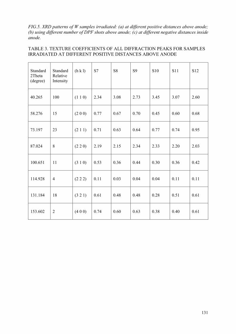
131
FIG.5. XRD patterns of W samples irradiated: (a) at different positive distances above anode; (b) using different number of DPF shots above anode; (c) at different negative distances inside anode.
TABLE 3. TEXTURE COEFFICIENTS OF ALL DIFFRACTION PEAKS FOR SAMPLES IRRADIATED AT DIFFERENT POSITIVE DISTANCES ABOVE ANODE
Standard 2Theta (degree)
Standard Relative Intensity
(h k l) S7 S8 S9 S10 S11 S12
40.265 100 (1 1 0) 2.34 3.08 2.73 3.45 3.07 2.60
58.276 15 (2 0 0) 0.77 0.67 0.70 0.45 0.60 0.68
73.197 23 (2 1 1) 0.71 0.63 0.64 0.77 0.74 0.95
87.024 8 (2 2 0) 2.19 2.15 2.34 2.33 2.20 2.03
100.651 11 (3 1 0) 0.53 0.36 0.44 0.30 0.36 0.42
114.928 4 (2 2 2) 0.11 0.03 0.04 0.04 0.11 0.11
131.184 18 (3 2 1) 0.61 0.48 0.48 0.28 0.51 0.61
153.602 2 (4 0 0) 0.74 0.60 0.63 0.38 0.40 0.61

132
TABLE 4. TEXTURE COEFFICIENTS OF ALL DIFFRACTION PEAKS FOR SAMPLES IRRADIATED WITH DIFFERENT NUMBER OF DPF SHOTS ABOVE ANODE
Standard 2Theta (degree)
Standard Relative Intensity
(h k l) S13 S14 S15 S16 S17 S18
40.265 100 (1 1 0) 2.19 2.69 1.31 3.36 3.32 3.03
58.276 15 (2 0 0) 0.80 0.59 0.99 0.37 0.49 0.55
73.197 23 (2 1 1) 0.86 0.76 0.89 0.51 0.60 0.70
87.024 8 (2 2 0) 2.17 2.23 1.10 2.45 2.45 2.18
100.651 11 (3 1 0) 0.51 0.43 0.95 0.35 0.35 0.40
114.928 4 (2 2 2) 0.17 0.11 0.64 0.06 0.03 0.05
131.184 18 (3 2 1) 0.66 0.59 0.91 0.46 0.46 0.53
153.602 2 (4 0 0) 0.64 0.61 1.21 0.43 0.29 0.56

133
TABLE 5. TEXTURE COEFFICIENTS OF ALL DIFFRACTION PEAKS FOR SAMPLES IRRADIATED AT DIFFERENT NEGATIVE DISTANCES INSIDE ANODE
Standard 2Theta (degree)
Standard Relative Intensity
(h k l) S19 S20 S21 S22 S23 S24 S25
40.265 100 (1 1 0) 2.49 2.96 2.93 3.23 3.08 2.92 3.15
58.276 15 (2 0 0) 0.76 0.51 0.59 0.56 0.67 0.61 0.64
73.197 23 (2 1 1) 0.69 0.58 0.66 0.42 0.57 0.73 0.57
87.024 8 (2 2 0) 2.25 2.68 2.41 2.58 2.39 2.31 2.31
100.651 11 (3 1 0) 0.51 0.31 0.37 0.31 0.32 0.33 0.31
114.928 4 (2 2 2) 0.17 0.03 0.04 0.03 0.03 0.05 0.04
131.184 18 (3 2 1) 0.55 0.44 0.46 0.35 0.48 0.53 0.48
153.602 2 (4 0 0) 0.59 0.48 0.55 0.51 0.45 0.53 0.50
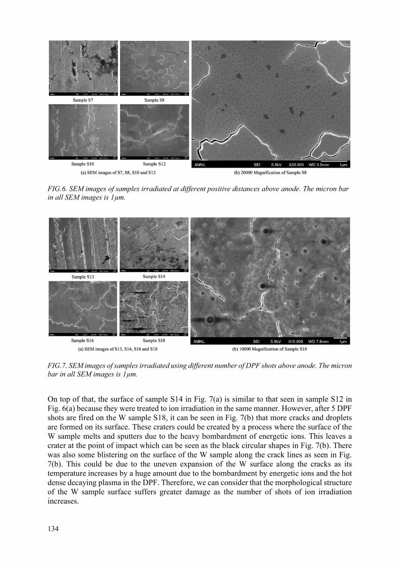
134
FIG.6. SEM images of samples irradiated at different positive distances above anode. The micron bar in all SEM images is 1µm.
FIG.7. SEM images of samples irradiated using different number of DPF shots above anode. The micron bar in all SEM images is 1µm.
On top of that, the surface of sample S14 in Fig. 7(a) is similar to that seen in sample S12 in Fig. 6(a) because they were treated to ion irradiation in the same manner. However, after 5 DPF shots are fired on the W sample S18, it can be seen in Fig. 7(b) that more cracks and droplets are formed on its surface. These craters could be created by a process where the surface of the W sample melts and sputters due to the heavy bombardment of energetic ions. This leaves a crater at the point of impact which can be seen as the black circular shapes in Fig. 7(b). There was also some blistering on the surface of the W sample along the crack lines as seen in Fig. 7(b). This could be due to the uneven expansion of the W surface along the cracks as its temperature increases by a huge amount due to the bombardment by energetic ions and the hot dense decaying plasma in the DPF. Therefore, we can consider that the morphological structure of the W sample surface suffers greater damage as the number of shots of ion irradiation increases.

135
Fig. 8 shows the surface morphology of W sample S19 (Control) and samples exposed inside the hollow anode at negative distances below the anode top; S21 (z=-8 mm), S23 (z=-24 mm) and S25 (z=-40 mm). From these images, we can see that cracks are observed on the surface of W samples S21, S23 and S25. The depth of the cracks increases as the W samples are exposed to electron irradiation at a greater negative distance below the top of the anode. This can be seen in Fig. 8(a) where the contrast between the surface and the cracks is greater in sample S25 as compared to the sample S21. This implies that the penetration strength of the relativistic electrons is greater at a further distance below the top of the anode.
FIG. 8. SEM images of samples irradiated at different negative distances inside anode. In (a), the micron bar in all SEM images is 1µm. In (b), the micron bar in SEM image is 10µm.
On top of that, all W samples still retain some parts of the polished surface observed on the surface of sample S19. This can be deduced by the white lines observed in all SEM images of samples S21, S23 and S25. This suggests that the impact of electron bombardment is weaker as compared to that of ion bombardment seen in previous paragraphs. Furthermore, there are no white spots and cavities on the surface of these samples. This could mean that electron bombardment is not strong enough to cause the sputtering and melting of W. However, as the exposure distance of the W sample below the top of the anode increases, more hairline cracks could be seen along the deep cracks. This is observed in sample S25 Fig. 7(b) which has an exposure height of z=-40 mm below the top of the anode. Even though the impact of electron bombardment is weaker than that of ion bombardment, we can consider that it gets relatively stronger and has more penetration damage as the exposure height below the top of the anode increases. Figure 9 shows the XPS results for W sample S12. The XPS results for W samples S18 and S25 were also similar to that of sample S12.

136
FIG. 9. XPS results of W sample irradiated at 50 𝑚𝑚 above anode.
From Fig. 9(a), we can observe that some copper can be found on the surface of the irradiated W samples exposed at positive and negative distances. The copper could be deposited on the sample surface due to the ablation of the copper anode. However, there were no copper crystallites found in the XRD results. One of the possible reasons to account for this would be that the detected copper may be in its amorphous phase and also in very small amount and hence it could not be detected during the XRD analysis. On top of that, the XRD analysis has a penetration depth of ≈ 1 μm while the XPS analysis has a penetration depth of only ≈ 10 nm. Hence, we can deduce that the deposited copper content is very little and has no signatures in the XRD results. Fig. 8(b) shows that some W oxide was found on the surface of the W samples. This could be explained by the oxidation of the samples when they were exposed to the atmosphere after removing them from the DPF.
Table 6 shows the average micro-hardness values of the W samples S7 (Control), S8 (z=10 mm), S12 (z=50 mm), S20 (z=0 mm) and S25 (z=-40 mm). The micro-hardness of samples was measured at multiple points on the surface and the average was taken as a representation of the entire sample.
TABLE 6. MICRO-HARDNESS OF W SAMPLES S7, S8, S12, S20 AND S25
Sample Number Micro-hardness (HV) ± Standard Error
S7 930±19
S8 840±31
S12 871±19
S20 786±29
S25 889±32

137
From Table 6, we can see that the micro-hardness of the control sample S7 was the highest as compared to the other samples. The change in the micro-hardness values could be explained by the exposure to the argon plasma which will create defects on the surface of the irradiated samples. This will reduce the hardness of the sample surface as compared to exposing the samples to carbon or nitrogen plasma, which will react with the surface to form carbides and nitrides respectively and increase the hardness values instead. The presence of copper, as seen in Fig. 7, will also reduce the hardness of the surface since copper has a lower hardness value as compared to W.
We can also observe that W samples S12 and S25, which have a greater exposure distance from the top of the anode, had a smaller reduction in their micro-hardness values as compared to samples S8 and S20 which have a smaller exposure distance from the top of the anode. This can be attributed to lesser structural defects as the ion/electron energy flux will reduce at greater distance of exposure due to beam divergence as well as due to lesser amount of copper deposition at greater distance of exposure, both above and below the anode top.
4. W PROCESSING USING RF NITROGEN PLASMA, DEPOSITION OF CARBON@W AND W@W AND THEIR IRRADIATION STUDIES IN DPF
The experiments performed during second year include preparation of four (4) samples of tungsten coated with about 100 nm tungsten thin films (W@W) by using pulsed laser deposition facility, three (3) samples of tungsten coated with about micron thin carbon thin films (carbon@W) and 2 samples of tungsten treated with RF nitrogen plasma for 15 minutes and 30 minutes at RF discharge plasma power of 200 W. All these were exposed to D2 Plasma by using UNU-ICTP DPF device.
In order to deposit the thin film of tungsten using PLD, the PLD deposition chamber was evacuated up to 4.5 × 10⁻⁷ Torr. Thereafter, 532 nm Nd:YAG laser at 10 Hz repletion rate and 4.73 J∙cm-2 energy fluence was shined on the 0.1 mm thick tungsten foil which is used as a tungsten target. The distance between the tungsten substrate and tungsten target was kept at 5 cm during the entire deposition. PLD deposition was carried out for 20 minutes which is equivalent to 12,000 shots. The carbon deposition on the tungsten substrate was done using the typical 3 kJ UNU-ICTP DPF device that uses 19 mm diameter anode. The 19 mm diameter copper anode was fitted with a graphite top. The anode length was about 160 mm was used and the cathode-anode gap was 32 mm. The DPF was operated in methane at a pressure of 2 mbar. The methane was used as an additional source of carbon precursor needed for carbon thin film deposition. The tungsten samples were placed at a distance of 15 cm from the anode tip and five consecutive shots were fired for the carbon deposition. For each shot, a fresh gas fill was used to replenish carbon precursor. A total of 4 samples of carbon@W were prepared at the same condition. The RF plasma treatment of four tungsten samples was performed using 200 W nitrogen plasma, two for a duration of 15 min and two for 30 min.
For irradiation experiments, the DPF was operated at 4 mbar of pressure of deuterium and we were able to get a very sharp and focus pinch, as shown by the signal in Fig. 10. The neutron yield obtained from this DPF expected to be about 1 × 10⁸ neutrons per shot.

138
FIG. 10. Voltage and di/dt waveform in the dense plasma focus device operated in deuterium plasma.
4.1. Effect of nitrogen RF plasma treatment on W substrates
4.1.1. Structural studies
In order to understand the phase and the crystallite size of the RF nitrogen plasma treated tungsten samples, X ray diffraction was carried out using Siemens X ray Diffractogram in detector scan mode. The diffraction spectra were refined using Rietveld refinements in TOPAS software. The Rietveld-refined spectra show reasonably good fit between the experimental XRD data and fitted XRD data as shown in Figs 11(a)–(b). Figs 11(a)–(b) show the XRD spectra of tungsten film exposed to RF plasma for 15 min at 200 Watt and 30 min at 200 Watt respectively. Sharp diffraction peaks observed at 40.25˚, 58.23˚, 73.16˚, 86.96˚, 100.59˚ and 114.87˚ correspond to (011), (002), (211), (022), (031) and (222) planes respectively. The diffraction spectra were indexed to Im-3m (space group number 229) with lattice parameter, a = 3.166 Å. Average crystallite size was calculated using Scherrer formula which showed average particle size of 9.7 nm.

139
FIG. 11. (a) X ray diffraction of nitrogen RF plasma exposed tungsten film for 15 minutes at 200 Wat; (b) Nitrogen RF plasma exposed tungsten film for 30 minutes at 200 Watt. The spectra in black shows the experimental data recorded using detector scan keeping the X ray tune angle at 1. The spectrum in red represents the Rietveld-refined X ray diffraction fitted with space group Im-3m (space group number 229). The spectrum in blue shows the difference between the experimental data and theoretically fitted data
4.1.2. Morphological studies
In order to understand the effect of the nitrogen RF plasma on the surface of tungsten, scanning electron microscopy (SEM- JEOL) was carried performed. Figs 12(i)(a–c) shows the SEM images at different magnifications of the RF treated samples for 15 min at 200 W. It can be seen clearly that the nanostructurisation process on the surface of the tungsten had just reached its initial stages. The tungsten before plasma treatment were manually/mechanically polished using emery papers of different grades. The linear line marks of manually polished samples can still be seen in sample treated with 15 minutes RF nitrogen plasma. The tungsten sample treated with 15 minutes of nitrogen plasma shows less surface feature. Even at the magnification of 50000 the nanostructurization marks are barely visible. However, as the exposure time is increased from 15 min to 30 min, we could clearly observe some changes on the tungsten surface as shown in Figs 12(ii)(a–c). First of all, the density of rough features on the 30 minute irradiation sample increases significantly as can be noticed from comparison of Fig. 11(i)(a) and Fig. 12(ii)(a) and secondly at higher magnification of 50000 marks a clear appearance of nano-sized features can be observed.

140
(i) (a) (i) (b) (i) (c)
(ii) (a) (ii) (b) (ii) (c)
FIG. 12. SEM of Nitrogen RF plasma exposed samples. (i) 15 minutes exposure; (ii) 30 minutes exposure.
4.1.3. Effect of DPF Irradiation on Nitrogen RF Plasma treated Tungsten:
Both RF nitrogen plasma processed samples were treated to two DPF shots operated in deuterium to exposure sample to hot dense decaying plasma, plasma jet stream, instability accelerated ions and neutrons. Tungsten exposed with 15 minutes nitrogen RF plasma shows melting and solidification of the sample surface with large number of crack formation seen particularly well in Figs 13(i)(b–c). However, for the 30 minutes exposed nitrogen RF sample almost no cracks were observed. The surface morphology interestingly is very different from the 15 min treated sample as shown in Figs 13(ii)(a–c). This may be attributed to the RF nitrogen plasma created nano-structurized tungsten surface due to prolonged 30 min treatment.

141
(i) (a) (i) (b) (i) (c)
(ii) (a) (ii) (b) (ii) (c)
FIG. 13. SEM of 2 shots Deuterium plasma exposed RF plasma treated samples. (i) 15 minutes exposure; (ii) 30 minutes exposure.
This is a remarkable result verifying the hypothesis the substantial nanostructurization of the tungsten surface may help in mitigation of surface damage by DPF plasma and radiation exposure. Since we have not yet conducted XPS measurements the extent and type of nitrogen functionalization/doping is not yet established. We did the EDX (energy dispersive X ray) measurement during SEM, but since the sensitivity towards nitrogen is very low, the nitrogen was not detected. The XRD measurements (not included) did not show any tungsten nitride phase formation. Hence, the nitrogen, if any, is in probably in amorphous form or the nitride phase is in scattered nano-crystalline form.
4.2. Effect of Carbon Thin Film Deposition using DPF on Tungsten substrates
The effect of deposition of a thick layer of carbon on tungsten on exposure to deuterium operated UNU-ICTP DPF device was also studied. A graphite top anode was used for the deposition with methane as the operating gas. The pressure within the chamber was set at 2 mbar and the deposition distance was 15 cm from the anode tip. The deposition was done using 5 DPF focus after conditioning. The distance was set such that the high energy ions flux would reduce substantially on the sample surface so as to create no damage to the tungsten samples. Since the anode and the operating gas contains carbon, a thick layer of carbon is expected on the sample surface. Four (4) such tungsten samples were prepared so as to study the effect of exposure of the deuterium plasma.
4.2.1. Structural studies
The carbon@W samples were subjected to X ray diffraction measurement to investigate the structural studies. The diffraction pattern (Fig. 14) did not show any change in the structure after exposing the carbon deposited tungsten confirming that no extra phase of W-C is formed after plasma exposure.
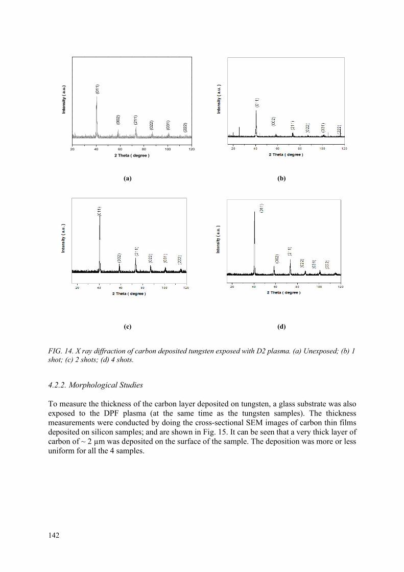
142
(a) (b)
(c) (d)
FIG. 14. X ray diffraction of carbon deposited tungsten exposed with D2 plasma. (a) Unexposed; (b) 1 shot; (c) 2 shots; (d) 4 shots.
4.2.2. Morphological Studies
To measure the thickness of the carbon layer deposited on tungsten, a glass substrate was also exposed to the DPF plasma (at the same time as the tungsten samples). The thickness measurements were conducted by doing the cross-sectional SEM images of carbon thin films deposited on silicon samples; and are shown in Fig. 15. It can be seen that a very thick layer of carbon of ~ 2 µm was deposited on the surface of the sample. The deposition was more or less uniform for all the 4 samples.
20 40 60 80 100 120
(222)
(031
)
(022
)
(211)
(002)
Inte
nsity
( a.u
.)
2 Theta ( degree )
(011)

143
(a) (b) (c)
FIG. 15. Cross sectional SEM images of the glass substrate exposed to DPF plasma for carbon deposition
To understand the distribution of the carbon layer on the surface of the tungsten, SEM analysis was also conducted on the top surface of the tungsten samples where the deposition was done. Fig. 16 shows the surface of an untested sample at different magnifications. It can be seen that the deposition on the surface of tungsten has uniform background with many carbon clusters scattered at different places. There are no visible polishing marks of the tungsten substrate and very few cracks visible on the surface. At the higher magnifications, Figs 16 (b–c), flakes of the carbon deposition can be seen. The layers seem to be adhering to one another and are bound to the tungsten substrate. There seem to be a thick layer of carbon deposited on tungsten surface similar to the observations from the cross-sectional SEM.
(a) (b) (c)
FIG. 16. SEM images of the surface of the carbon deposited tungsten samples. (a) 1000×; (b) 5000×; (c) 50000×.
From Fig. 16 and the morphological studies, it can be concluded that a good thick layer of carbon deposition was achieved on the surface of the tungsten samples. The layer seems to be evenly distributed across the sample surface and there seemed to be no region without any carbon on the surface of the tungsten sample. The Raman spectroscopy was also performed on carbon@W samples before and after DPF irradiation which are discussed separately later.
4.2.3. Effect of DPF Shots Irradiation on carbon@W samples
To study the effect of D2 plasma on the surface of the carbon coated tungsten samples, different samples were exposed to different number of DPF shots in a deuterium environment. The

144
morphology of the samples seem to change with exposure to D2 plasma. Figs 17 (i–iii) shows the change in morphology of the carbon coated tungsten samples with 1, 2 and 4 shots of D2 Plasma using DPF. The polishing marks of the surface of the tungsten seem to have reappeared after the first shot as shown in Fig. 17(i)(a) which means that most of the carbon deposited on the surface seemed to have been etched out. At higher magnifications, flakes could be found on the surface of the sample which could mean that some carbon still exist on the surface of tungsten. For the sample exposed to 2 shots of D2 plasma, the surface seems to be modified by the plasma. Nanostructures seemed to be forming on the surface of the tungsten as shown in Figs 17(ii). This effect was amplified in the samples exposed to 4 plasma shots shown in Figs 17(iii). The sample surface has been completely modified in this case and the surface shows the formation of nanostructures better than the exposure to Nitrogen RF plasma for 30 minutes. The carbon seems to be completely removed from the sample surface. Thus, a carbon overcoat for the protection of the tungsten samples would not be effective in the presence of D2 plasma.
(i) (a) (i) (b) (i) (c)
(ii) (a) (ii) (b) (ii) (c)
(iii) (a) (iii) (b) (iii) (c)
FIG. 17. SEM images of the top surface of tungsten samples with carbon deposition. (i)1 shot exposure of D2 plasma at 1000×; (ii) 2 shots exposure of D2 plasma at 5000×; (iii) 4 shots exposure of D2 plasma at 50,000×.

145
4.2.4. Raman Spectroscopy of carbon coated tungsten samples:
To ascertain the presence of carbon on the surface of the tungsten and to analyse the type of carbon deposition Raman spectroscopy was used. Raman spectra of all the tungsten coated with carbon were studied before and after exposure to D2 plasma using the Renishaw Raman spectrometer with 632 nm. Fig. 17(a) shows the Raman spectra of all the as synthesized carbon@W samples. It can be seen that all the carbon deposited samples show the characteristic D and G peak of graphite at 1338 cm-1 and 1586 cm-1 respectively. There is also a 2D peak around 2900 cm-1. Thus, the deposited layer seen in the cross sectional SEM of the glass substrate and the surface SEM of the tungsten substrate is made of carbon. The presence of large D and 2D peaks signify the amorphous nature of the deposited carbon. From the shift in the G peak and the ratio of I(D)/I(G), it can be estimated that the deposited carbon is graphitic with very less sp3 content. Thus, the deposited layer may not have very good mechanical properties. This was verified earlier the carbon films was remove after DPF exposures.
1000 1500 2000 2500 3000
Inte
nis
ty (
a.u
)
Raman Shift (cm-1)
4 shots 2 shots 1 shot
1000 1500 2000 2500 3000
G
Inte
nis
ty (
a.u
)
Raman Shift (cm-1)
S30 S28 S27 S26
Carbon@WD
2D
(a) (b)
FIG. 18. (a) Raman Spectra of the untested samples; (b) carbon coated tungsten samples exposed to 1, 2 and 4 shots of D2 Plasma.
Fig. 18(b) shows the Raman spectra of samples exposed to different shots of D2 Plasma. For the samples exposed to D2 plasma, it was difficult to obtain a good spot to conduct the Raman Spectroscopy. The spectra seemed to shift with exposure to DPF plasma. After 2 shots, the I(D)/I(G) seemed to be decreasing which would indicate the increase in sp3 content on the surface. After 4 shots, there seems to be carbon peak on the sample surface. Thus, the carbon coated on the surface has been completely etched out by the D2 plasma. This corroborates with the evidence from the morphological studies.
4.3. Tungsten thin film on tungsten (W@W) substrate and their DPF irradiation
4.3.1. Structural Studies
Figure 19(a) shows the XRD spectra of tungsten film deposited on the tungsten substrates using the PLD technique. The detail of deposition parameters and conditions are given in the Section 2.2. XRD pattern obtain for the tungsten thin film shows the sharp reflections corresponding to (011), (002), (211), (022), (031) and (222) planes respectively, clearly indicating the formation of body centred cubic structure of tungsten as shown in Fig. 19(a). The diffraction
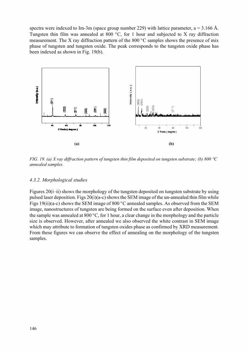
146
spectra were indexed to Im-3m (space group number 229) with lattice parameter, a = 3.166 Å. Tungsten thin film was annealed at 800 C, for 1 hour and subjected to X ray diffraction measurement. The X ray diffraction pattern of the 800 C samples shows the presence of mix phase of tungsten and tungsten oxide. The peak corresponds to the tungsten oxide phase has been indexed as shown in Fig. 19(b).
(a) (b)
FIG. 19. (a) X ray diffraction pattern of tungsten thin film deposited on tungsten substrate; (b) 800 C annealed samples.
4.3.2. Morphological studies
Figures 20(i–ii) shows the morphology of the tungsten deposited on tungsten substrate by using pulsed laser deposition. Figs 20(i)(a-c) shows the SEM image of the un-annealed thin film while Figs 19(ii)(a-c) shows the SEM image of 800 C annealed samples. As observed from the SEM image, nanostructures of tungsten are being formed on the surface even after deposition. When the sample was annealed at 800 C, for 1 hour, a clear change in the morphology and the particle size is observed. However, after annealed we also observed the white contrast in SEM image which may attribute to formation of tungsten oxides phase as confirmed by XRD measurement. From these figures we can observe the effect of annealing on the morphology of the tungsten samples.

147
(i) (a) (i) (b) (i) (c)
(ii) (a) (ii) (b) (f)
FIG. 20. Scanning electron micrograph of tungsten thin film deposited using pulse laser deposition technique. (i) As deposited; (ii) 800 C annealed.
PLD grown thin films were also subjected to deuterium plasma using the dense plasma focus. The thin films were exposed with 1, 2, and 4 DPF shots. The SEM images are recorded after deuterium plasma and show in Fig. 21 for all shots. Fig. 21(i) (a-c) shows the SEM image of 1 shot and reveals the formation of nanostructures on the surface of tungsten. However, SEM images recorded for 2 shots and 4 shots of deuterium plasma do not show nanostructures as observed for 1 shot. This may be due to local heating effect on the surface from transfer of the high plasma energy to the surface as shown in Fig. 21(ii). The large localize temperature on the surface may lead to the densification of the nanostructures due to Ostwald ripping. Moreover, SEM image of 4 plasma shots shows the cracks on the surface of the tungsten as shown in Fig. 20(iii).
Figs 22(i–ii) shows the SEM images of the surface of the tungsten deposited on tungsten samples after annealing before and after exposure to 2 shots of D2 plasma. Compared to the tungsten samples without annealing, the surface seems to be modified with nanostructures after annealing as shown in Fig. 22(i). Nanoparticles of tungsten oxide of size ~ 50 nm are present on the surface of the sample after annealing (see Fig. 22(i)–(c)). The presence of these nanostructures could help in mitigating the damage due irradiation by hot dense plasma, energetic ions and neutrons in DPF device. However, it was noticed from Fig. 22(ii) that the nanostructured tungsten coating in this case did not survive, it was rather melted and solidified as seen in Fig 22(ii)(c) which blisters formation and large cracks can be noticed. This is in contrast with the nanostructured tungsten surface that was created by nitrogen RF plasma processing which was able to withstand the DPF plasma exposure quite well.

148
(i) (a) (i) (b) (i) (c)
(ii) (a) (ii) (b) (ii) (c)
(iii) (a) (iii) (b) (iii) (c)
FIG. 21. Scanning electron micrograph of dense deuterium plasma exposed PLD grown W@W samples. (i) One shot; (ii) two shots; (iii) 4 shots irradiation.

149
(i) (a) (i) (b) (i) (c)
(ii) (a) (ii) (b) (f)
FIG. 22. SEM images of the tungsten deposited on tungsten using PLD after annealed in the presence of oxygen. (i) Before exposure; (ii) after exposure to 2 shots of D2 Plasma.
5. W SUBSTRATE NITRIDING USING RF AND DPF PLASMA AND WN COATINGS AND THEIR DPF IRRADIATION STUDIES
5.1. Experiment Methods
From the experiments conducted during the previous years of the CRP project, it was seen that the most effective strategy to improve the performance of tungsten under plasma conditions were to create nanostructures on the surface of the tungsten substrate. This idea has been expanded further during the third year of project and extensively analysed. In this particular study during the third of the project, 4 different surface treatments were used to improve the performance of the samples as listed below:
(a) Creating nanostructures on the surface using RF plasma; (b) Surface nitriding of the tungsten substrates using N2 DPF plasma; (c) Surface nitriding of tungsten substrates with surface nanostructures; (d) Sub-100 nm tungsten thin film deposition using tungsten anode top ablation in argon
operated dense plasma focus; (e) Deposition of sub-100 nm thin film of tungsten on tungsten substrates in a nitrogen
environment using N2 DPF plasma.
The 10 × 10 × 1 mm tungsten substrates used for this study were purchased from PLANSEE, Austria. Before any surface treatment, the surface roughness of the samples was quite high as can be seen by clear criss-cross marks/lines on as received samples. The sample surface was made uniform with features sizes ~1 µm by polishing the samples using a Struers LaboPol grinding/polishing machine. The sample was then cleaned using an ultrasonicator in acetone,
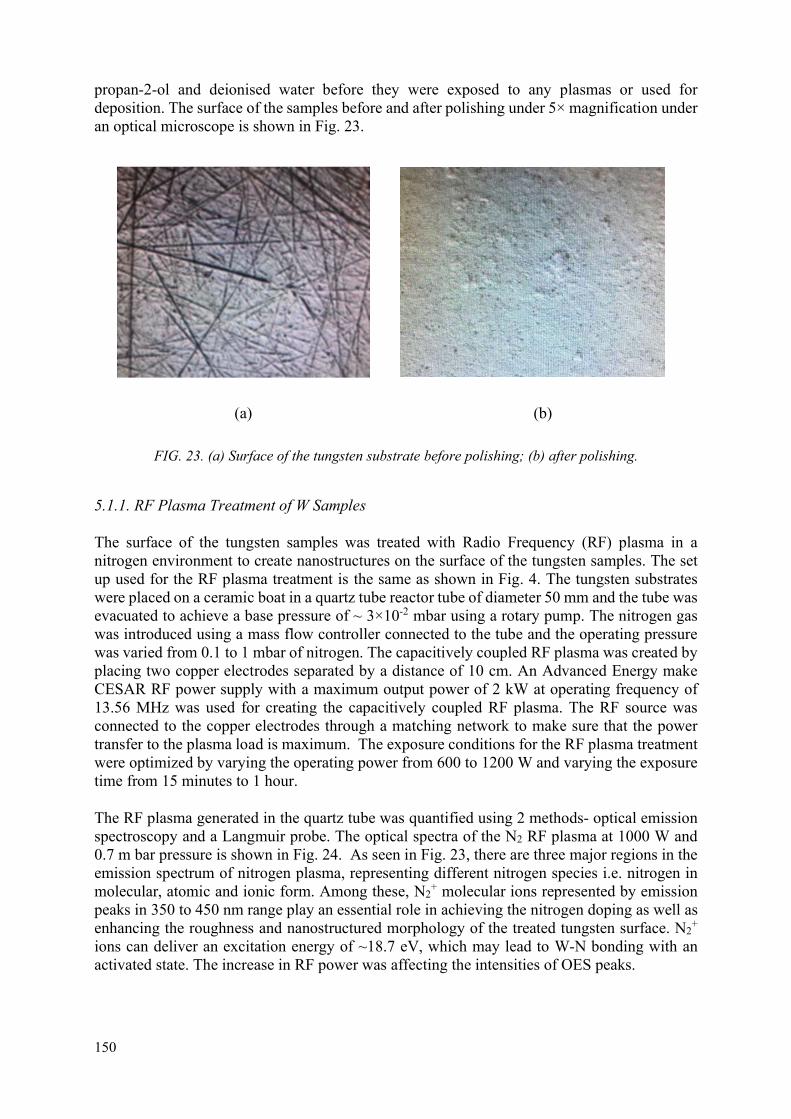
150
propan-2-ol and deionised water before they were exposed to any plasmas or used for deposition. The surface of the samples before and after polishing under 5× magnification under an optical microscope is shown in Fig. 23.
(a) (b)
FIG. 23. (a) Surface of the tungsten substrate before polishing; (b) after polishing.
5.1.1. RF Plasma Treatment of W Samples
The surface of the tungsten samples was treated with Radio Frequency (RF) plasma in a nitrogen environment to create nanostructures on the surface of the tungsten samples. The set up used for the RF plasma treatment is the same as shown in Fig. 4. The tungsten substrates were placed on a ceramic boat in a quartz tube reactor tube of diameter 50 mm and the tube was evacuated to achieve a base pressure of ~ 3×10⁻² mbar using a rotary pump. The nitrogen gas was introduced using a mass flow controller connected to the tube and the operating pressure was varied from 0.1 to 1 mbar of nitrogen. The capacitively coupled RF plasma was created by placing two copper electrodes separated by a distance of 10 cm. An Advanced Energy make CESAR RF power supply with a maximum output power of 2 kW at operating frequency of 13.56 MHz was used for creating the capacitively coupled RF plasma. The RF source was connected to the copper electrodes through a matching network to make sure that the power transfer to the plasma load is maximum. The exposure conditions for the RF plasma treatment were optimized by varying the operating power from 600 to 1200 W and varying the exposure time from 15 minutes to 1 hour.
The RF plasma generated in the quartz tube was quantified using 2 methods- optical emission spectroscopy and a Langmuir probe. The optical spectra of the N2 RF plasma at 1000 W and 0.7 m bar pressure is shown in Fig. 24. As seen in Fig. 23, there are three major regions in the emission spectrum of nitrogen plasma, representing different nitrogen species i.e. nitrogen in molecular, atomic and ionic form. Among these, N2
+ molecular ions represented by emission peaks in 350 to 450 nm range play an essential role in achieving the nitrogen doping as well as enhancing the roughness and nanostructured morphology of the treated tungsten surface. N2
+ ions can deliver an excitation energy of ~18.7 eV, which may lead to W-N bonding with an activated state. The increase in RF power was affecting the intensities of OES peaks.

151
The V-I curve of a compensated single probe Langmuir probe measured in the RF plasma is given in Fig. 25(a). The electron temperature was calculated at different powers and different operating pressures in a nitrogen environment and is as shown in Fig. 25(b). The optimal operating pressure was estimated from the plasma characterization techniques. It can be seen that at low flow rates, the electron temperature is highest when the operating power is low. There seems to be an optimal operating power for each flow rate for maximising the plasma electron temperature. The electron density was calculated from the OES spectra using the electron temperature obtained from the Langmuir probe measurements. For most effective synthesis of nanostructures on the surface, it is not only important to have high plasma temperature but also the high plasma density. Thus, the operating pressure was chosen to be 0.7 mbar which had a moderately high electron temperature and high electron density. The optimization for the best operating power and time duration was later done using SEM analysis of the sample surface after treatment.
FIG. 24. Emission spectra of nitrogen plasma at 1000 W, 0.7 mbar pressure.
(a) (b)
FIG. 25. (a) Applied voltage vs probe current in a single probe Langmuir probe measured for the capacitively coupled RF plasma; (b) the plasma temperatures measured at different operational power for different operating gas pressures of nitrogen from 0.1 to 0.9 mbar.

152
5.1.2. DPF plasma-based surface modifications
The dense plasma focus device can be used for a variety of surface modifications based on the operating parameters. Since the device can produce hot dense decaying plasma after the pinch phase with very high energies in keV together with instability accelerated keV to MeV range ions of filling gas species, it can be used for different surface treatments based on the operating conditions. In this study, three different approaches are pursued for improving the surface hardness of the tungsten substrates. The basic idea stems from the fact that the hardness of tungsten nitride is in the range of 30 GPa while that of tungsten is around 8 GPa. Thus, the DPF plasma exposure of the samples is expected to improve its hardness considerably if nitriding of the sample can be done. The schematic of the DPF device is shown in Fig. 1. The design of the UNU-ICTP DPF device is such that if the working pressure is appropriate, the pinch column is formed when the plasma current is maximum. This will ensure that the compression force is maximum and thus the plasma temperature and density can achieve highest possible values of ~1-2 keV and ~1025-26 m-3.
The plasma temperature and density can be controlled by controlling the pinching efficiency of the DPF device which is essentially controlled by operating gas pressure and by moving away from the optimal pinch conditions. When the pressure is such that the current maximum coincides with the pinch formation, the plasma temperature is highest. This mode of operation of the dense plasma focus device is called the ‘focused mode operation’. Since the plasma temperature is the highest in this mode and moreover the m=0 instabilities are commonly formed leading to generation of relativistic electron beam which move toward the anode and can be used to efficiently ablate the material placed at the anode tip and thus can be used for deposition. Since the high energy ions are also generated which move towards the top of the chamber, this mode of operation may also damage the surface of the sample if the sample is placed too close to the anode tip. If the operating pressure is such that the current maximum does not coincide with the pinch, this mode of operation is called ‘off-focus mode operation’. Even though the compression of the pinch plasma column isn’t optimal, compression still happens, and the plasma temperature is still in the 100 s of eV range. In this mode of operation, the plasma energy can be controlled, and instability accelerated ions/electrons can be removed and hence the damage to the sample can be considerably reduced. This plasma can thus be used for surface treatment of the tungsten samples. The energy of the plasma produced in this case is still much higher than the 8–10 eV produced in the case of the RF plasma system.
5.1.2.1. Nitriding the surface of the W samples
The dense plasma focus was operated in the non-focus mode in a nitrogen environment for nitriding the surface of the tungsten samples. The operating pressure was modulated such that the pinch did not occur at the maximum current. The pinch condition was ascertained from the voltage probe signal, for example the voltage probe signal shown in Fig. 26 depicts the efficient focusing mode as a very sharp and intense voltage peak is obtained at about 3-4 s. Since the dense plasma focus device can be modelled as a RLC circuit with very small resistance, the current in the circuit is 90o out of phase with respect to voltage. Thus, the current maximum occurs at the zero crossing of the voltage signal. The operating pressure was set such that the pinch occurred after the zero crossing of the voltage signal. For the non-focus mode operation, the voltage probe peak is either very weak or non-existent.

153
0 5 10 15 20
-4000
-2000
0
2000
4000
6000
8000
Vo
ltag
e (
V)
Time (s)
FIG. 26. Electrical characterization of DPF device operating in nitrogen environment for surface nitriding,
In order to avoid additional deposition of impurities due to anode ablation, a hollow copper anode was used for this study. The voltage characteristics mentioned in Fig. 25 was obtained when the operating gas pressure was 2 mbar (efficient focusing mode). Reducing the pressure even further would reduce the energy of the plasma substantially but this might hamper the surface nitriding of the samples. So, the pressure of 2 mbar was fixed for the nitriding of the tungsten samples using DPF. As the DPF device is operated in the focused mode, the energy of the plasma can be high enough to destroy the surface of the sample if the sample is placed too close to the anode tip. The plasma exposure distance was optimised by placing a 40 nm tungsten thin film coated on a silicon substrate (deposited using magnetron sputtering) at different distances of 10 cm, 16 cm and 23 cm for 5 shots and the surface damage was studied using SEM. The minimum distance where the same showed minimal damage was used for the exposure of the tungsten substrates. It was seen that exposure at 23 cm showed no apparent damage to the surface of the sample. Thus, the exposure distance was fixed to 23 cm from the anode tip. The tungsten substrates which were to be nitrided were exposed to 5 shots of DPF plasma in a N2 environment at 2 mbar operating pressure at a distance of 23 cm from the anode tip.
5.1.2.2. W and WN thin film deposition using DPF
The DPF device was also used to deposit a sub-100 nm thick tungsten and tungsten nitride thin film on the surface of the tungsten substrate by operating it in the focus mode using copper anode with a tungsten tip. The DPF device was operated in an inert Argon environment for the tungsten deposition where as in nitrogen environment for tungsten nitride to make sure that there are no other impurities occurring while depositing the tungsten thin films. The operating pressure in this case was fixed to 1.5 mbar argon for tungsten deposition and 2 mbar nitrogen for tungsten nitride which was close to the optimal focus so that anode ablation occurs, and material deposition happens. The operating pressure was selected such that the peak voltage observed during the pinch for both N2 and Ar gases were similar. The distance of deposition is also important for getting the optimal thickness. Exposing the tungsten substrates close to anode tip can result in thicker films but the plasma temperature in this region can damage the surface of the sample. Thus, the exposure distance needs to be optimised for getting the required thin

154
film thickness and uniformity. To study the thickness and uniformity of the films deposited, the deposition was done at different distances onto a silicon substrate and the thickness and roughness of the deposited films were studied.
5.1.3. Deuterium operated DPF with neutron and energetic deuterium plasma
For studying the effect of surface hardened tungsten samples to fusion conditions, the dense plasma focus device was operated in the focused mode in D2 environment such that nuclear fusion occurred with neutron production. The optimal pressure for operation was ascertained to be 4 mbar where the best pinch was observed at the current peak for the electrode configuration with a hollow copper anode in the UNU-ICTP DPF device. The samples were placed at 8 cm from the anode tip so that exposure can be done with temperatures close to fusion conditions. The samples with different surface conditions were exposed to 2 and 4 shots of DPF plasma and the changes to the surface morphology were studied after the exposure. We have earlier estimated the deuteron and neutron fluence in UNU-ICTP device at different distance from anode top [31]. “According to Faraday cup measurements done by Jiaji et al [32] for 3.0 kJ UNU/ICPT PFF, the ranges of the energies of the hydrogen ions were found to be from about 35 keV to about 1.5 MeV with the ion fluence of about 2.63×10¹⁴ ions cm−2 at sample position of 5 cm. The dense plasma focus devices exhibit universality in ion emission characteristics [21], i.e. ion energies and fluxes are not changed with the change in the operating gas. The estimated deuteron fluence is estimated to be about 1.03×10¹⁴ deuterons cm−2 at sample distance of 8 cm for UNU/ICTP PFF. The yield of 2.45 MeV neutron in this device has been measured to be about 108 neutrons per shot in entire 4 radian [33]; yielding the neutron fluence to be about 1.2×10⁵”3 neutrons cm−2 at the distances of 8 cm used in present work.
5.2. Results and discussion
This section is divided into 2 sections: (i) optimization of the different tungsten substrate surface hardening techniques; and (ii) exposure of the processed or tungsten coated tungsten substrate surfaces to D2 plasma and studying the changes in surface conditions after the plasma/neutron exposure. The optimization was done using different characterization techniques to get the optimal samples for with the appropriate surface structure which were later exposed to D2 plasma to study the effectiveness of these techniques.
5.2.1. Surface nanostructurization and nitriding of W substrates using nitrogen RF plasma
In this study, different tungsten substrates after polishing and cleaning with a surface roughness of ~ 1 µm were exposed to a capacitively coupled RF plasma. The nanostructurization was done in the N2 environment along with the formation of tungsten nitride phase on the surface if the plasma conditions are conducive for the same but the primary objective in this case was to create nanostructures on the entire surface. It is well known that recrystallization in W materials starts to occur at temperatures much less than the melting point temperature which leads to the formation of new random grain boundaries. The grain boundaries are planar defect where the atoms at grain boundary region are in strained position leading them to be at relatively much higher energy compared the grain bulk. Hence, grain boundaries are very susceptible to cracking and are prone to fracture which is commonly referred as embrittlement or in this case as recrystallization embrittlement as new grain boundaries are formed due to thermal load related recrystallization of plasma facing material. The formation of random grain boundaries is attributed to two main factors: (i) strong covalence of atomic bonding in W; and (ii) segregation and precipitation of oxygen and nitrogen gaseous interstitial atoms which are
155
insoluble in the W matrix. The recrystallization embrittlement of W is expected to be mitigated: (i) by replacing the weak cohesion at random grain boundaries with a strong interatomic bond; and (ii) by reducing the amount of insoluble interstitial impurities of oxygen and nitrogen to a negligible level. The radiation exposure induced embrittlement is caused mainly by increase in yield strength due to accumulation of radiation induced defects (radiation hardening). Accumulation of radiation induced defects can be suppressed by introducing a high density of sinks, such as grain boundaries and dispersions, for the defects. It has been found that nanostructured materials suffer suitable structural changes under radiation environments leading to significant increase in ductility compared with that in the unirradiated sample. This desirable phenomenon is referred as radiation induced ductilization (RIDU). RIDU can occur provided the beneficial effects of strengthening of the random grain boundaries due to radiation-enhanced and/or –induced segregation and precipitation of the constituent elements exceed the detrimental effects of radiation hardening. Hence, we first wanted to induce nanostructures on W substrate surface to investigate it impact on the hardness of the treated sample. From previous experience, it was seen that isolated nanostructures could be produced while operating at an RF power of 300 W. With this insight, the operating RF power and duration was varied so that nanostructures were observed on the surface of the tungsten substrates. Scanning electron microscopy was primarily used for the characterization of the samples for this optimization.
The surface of the samples after exposure to 30 minutes of RF plasma at 600 W, 800 W, 1000 W and 1200 W at different magnifications are shown in Fig. 26. It can be seen that at the lower power levels of 600 W and 800 W isolated nanostructures are visible on the surface of the sample. But there are regions on the surface of the sample which did not contain any nanostructures. Additionally, the size of nanostructures seems to vary a lot with most features about 20-30 nm but with many having feature size greater than 100 nm. At 1000 W, the entire surface was covered with well defined spherical nanostructures which were visible even at the lower magnifications. The size of the nanostructures were ~ 20 nm and looked uniform. When the power level was increased to 1200 W, even though the nanostructures were visible on the surface of the substrate, the shape of the structures was irregular. This indicated that at 1200 W, the RF plasma was too energetic leading to excessive etching of the nanostructures produced and thus the structures were irregular in shape. From this study, it was concluded that the optimal RF power required to produce nanostructures on the surface of the tungsten substrates were 1000 W while working in a 0.7 mbar N2 environment.
The optimal exposure time for the RF power of 1000 W was also studied by exposing the samples to the RF plasma for other processing durations of 15, 45, and 60 minutes and the surface morphology was studied using SEM. The SEM images, at different magnifications of 20000×, 50000× and 100000×, showing the changes in surface morphology after exposure to different time durations at 1000 W are shown in Fig. 27. It can be seen that very few nanostructures are observed in the samples exposed to 15 minutes which indicates that the exposure time is not enough for the production of significant number of nanostructures on the tungsten substrate surface. The samples exposed for 45 minutes showed extensive nanostructures on the entire surface, but the nanostructures were not as well defined compared to Fig. 28(iii) and the samples exposed to 60 minutes showed isolated nanostructures on the surface. Hence, the optimal exposure time for the synthesis of nanostructures on the surface of the samples were found to be 30 minutes. Below 30 minutes, there was not enough nanostructures were produced while when the exposure was more than 30 minutes, the nanostructures produced were destroyed by the RF plasma and thus the structures on the surface were less well defined and completely disappeared after 45 minutes and 60 minutes of RF plasma exposure respectively.

156
(i) (a) (i) (b) (i) (c)
(ii) (a) (ii) (b) (ii) (c)
(iii) (a) (iii) (b) (iii) (c)
(iv) (a) (iv) (b) (iv) (c)
FIG. 27. SEM images of the surface of the samples exposed to the capacitively coupled RF plasma. (i) 600W; (ii) 800 W; (iii) 1000 W; (iv) 1200 W for 30 minutes with an operating pressure of 0.7 mbar N2. It may be noted that SEM images in (a), (b) and (c) for different RF plasma power are at 20,000×, 50,000× and 100,000× with the size of micro bar as 1 m, 100 nm and 100 nm respectively. From the studies conducted to optimize the exposure of RF plasma to nanostructurize the surface of the tungsten substrates, it was found that optimal nanostructures were produced when the substrates were exposed to 1000 W RF plasma for 30 minutes. Three different samples were exposed to RF plasma under these conditions to prepare the nanostructured tungsten surface and later exposed to 2 and 4 shots of D2 plasma. Further characterization of these samples and changes in surface morphology after exposure to D2 plasma will be explained in section 5.2.3.

157
(i) (a) (i) (b) (i) (c)
(ii) (a) (ii) (b) (ii) (c)
(iii) (a) (iii) (b) (iii) (c)
FIG. 28. SEM images of the surface of the tungsten substrates exposed to 1000 W RF plasma. (i) 15 min; (ii) 45 min; (iii) 60 min in 0.7 mbar N2 environment. It may be noted that SEM images in (a), (b) and (c) for different RF plasma power are at 20,000×, 50,000× and 100,000× with the size of micro bar as 1 m, 100 nm and 100 nm respectively. 5.2.2. Structural analysis To investigate the effect of the RF nitrogen plasma on the surface of the tungsten substrate, XRD measurement was performed using the locked couple mode and also as a function of grazing angle 0.2–10. The observed XRD pattern is given in the Fig. 29. As clearly observed from the figure, lock coupled scan clearly shows the presence reflections corresponding to pure tungsten. However, when the angle of incident X ray is reduced, to the 10, the observed XRD pattern is similar to the lock-coupled pattern. The XRD pattern remain similar till 5 X ray incident angle. When the incident angle reduced below 5, clearly two distinct peaks are observed corresponding to the both tungsten and tungsten nitrides. As we further reduced to the incident angle to 0.2, we clearly observed the peak corresponding to the W2N phase, which indicates the RF plasma assisted formation of W2N phase at 1000 W.

158
FIG. 29. (a) X ray diffraction (XRD) of the tungsten substrates exposed to 1000 W RF plasma for 30 min in 0.7 mbar N2 environment; (b) enlarged view of the (100) reflection to present the observed shift form W to W2N in the XRD pattern.
5.3.3. Chemical analysis The best optimized RF plasma treated sample was chosen for the XPS measurements (Fig. 30). The XPS measurements were performed with Kratos AXIS Supra XPS that is equipped with an automated dual anode (Al/Ag Kα) X ray monochromatic source. The combination of high transmission hemispherical and spherical mirror analysers along with the use of delay-line detector enables outstanding spectroscopy. The XPS technique was used for the identification of different oxidation states with respect to their structures. The core level spectra of C (1s), O (1s), W (4f), and N (1s) were recorded. All the experimentally observed core level spectra were calibrated with the binding energy of C1s (284.6 eV). Core level W (4f) core level spectra shown in the Fig. 29 clearly reveals the presence of metallic tungsten and oxygen rich tungsten WOx. The binding energies of the W4f7/2 and W4f5/2 electrons are centred at 31.5 and 33.7 eV, respectively. The energy peak separation is 2.2 eV. The positions of binding energies for WOx 4f7/2 and WOx 4f5/2 electrons are centred at 35.5 and 37.8 eV, respectively. The W sub-oxide (WOx) located at 35.0 eV could be due to the native tungsten oxide layer on the surface of the tungsten surface. However, after exposure of substrate surface to the nitrogen plasma, the W sub-oxide suppress as observed from the relative intensity of the W4f5/2/WOx 4f5/2 and W4f7/2/WOx 4f7/2. In order to confirm the effect of the nitrogen plasma, and possibility of the tungsten oxynitrides, core level spectra of N (1s) and O(1s) was recorded for bare and 1000 W N2 plasma exposed tungsten. 1000 W N2 exposed tungsten surface clearly reveals the formation of tungsten nitride, as confirmed by the shift in the N (1s) core level binding energy from 400.1 eV to 396.9 eV on the surface of the tungsten. The core level spectra of O (1s) shows that after nitrogen plasma exposure the surface oxygen of the tungsten is removed and only the oxygen from the oxy-nitrides is observed. Hence, the 1000 W, RF plasma exposure on the tungsten results in the formation of tungsten oxy-nitrides.

159
FIG. 30. X ray photoelectron spectroscopy (XPS) of polished tungsten substrates and tungsten substrates exposed to 1000 W RF plasma for 30 min in 0.7 mbar N2 environment.
5.3.4. Sub-100 nm W and WN thin film deposition using DPF
The deposition of tungsten and tungsten nitride thin films was also done using the dense plasma focus device. The optimization in this case was done for the uniformity and the thickness of the film deposited using the DPF exposures. The surface roughness and thickness of the deposition were measured using AFM and it was seen that for 5 DPF shots, films of thickness 80-100 nm could be deposited. The optimization of film thickness was done using a silicon substrate (as PLANSEE tungsten substrates are very expensive). The thickness was measured using the step method wherein a portion of the sample was masked while deposition which was later washed away using acetone and the AFM was done at the same location to measure the change in height. Figure 31 shows the thickness measurement using AFM of the tungsten and tungsten nitride layer deposited on a silicon substrate using the dense plasma focus device. It was seen that the thickness of tungsten film was 60.9 nm while the thickness of the tungsten nitride film was 100 nm. The surface roughness of the thin films deposited were also studied using AFM as can be seen in Fig. 32. The roughness of the tungsten layer deposited on the silicone substrate was found to be 1.2 nm while the roughness of the tungsten nitride layer deposited was found to be 2 nm indicating highly uniform thin film deposition using DPF. From the thickness and roughness measurements, it was concluded that the thin films deposited onto the surface of the silicon substrate were of appropriate thickness and of high quality. Finally, three different tungsten substrates were coated with tungsten and tungsten nitride thin films; which were later exposed to 2 and 4 shots of deuterium operated DPF device to investigate the effect of neutron and radiation irradiation of coated samples.

160
i(a) i(b)
ii(a) ii(b)
FIG. 31. (i) Thickness of tungsten layer; (ii) tungsten nitride layer deposited using AFM on the silicon substrates.

161
i(a) i(b)
ii(a) ii(b)
FIG. 32. AFM surface scan of (a) W and (b) WN thin film deposited using the dense plasma focus device.
5.4. Characterization of surface treated W samples
The material and mechanical characterization of the surface treated tungsten samples were done before and after exposure to deuterium operated DPF device (for neutron, energetic plasma and radiation irradiation studies). The surface morphology was studied using SEM while the chemical changes during the surface treatment was studied using XPS. In this section the material characterization before the D2 plasma exposure is presented. The study includes 5 different sample types: (i) unexposed virgin tungsten substrate sample; (ii) W substrates with nanostructured surface by nitrogen RF plasma treatment; (iii) W substrate with surface containing tungsten nitride by nitrogen operated DPF device treatment; (iv) sub-100 nm tungsten coated tungsten (prepared in argon operated DPF device); and (v) sub-100 nm tungsten nitride coated tungsten (prepared in argon operated DPF device).
5.4.1. Characterization of surface treated tungsten samples before exposure to fusion conditions in DPF device
5.4.1.1. Morphological and chemical analysis
The surface morphology of all the sample types before deuterium plasma exposure were studied using scanning electron microscopy and whose results are shown in Fig. 33. The polished and cleaned unexposed samples (Fig. 33(i)) showed very fewer scratch marks and non-uniformity

162
even at 50,000× SEM magnification. Thus, the surface of the samples were flat with very good surface uniformity. Any changes in surface morphology after exposure to low-temperature, low-density but long-duration RF plasma and high-temperature, high-density but short-duration DPF plasma and energetic ions. Figure 33(ii) shows the surface of the sample after nitrogen RF plasma exposure were investigated. Nanostructures were synthesized on the surface of the sample caused by the nitrogen plasma etching on tungsten. Fig. 33(iii) shows the surface of the sample after exposure to 5 shots of DPF device at 2 mbar nitrogen. The exposure to 5 DPF focusing shots have resulting in smoothening of surface features on irradiated tungsten surface, showing that the high energy N2 plasma exposure might have resulted in surface restructuring due to surface melting followed by rapid solidification during intense transient thermal load from intense instability accelerated ions of filling gas species. The sample is also processed by highly transient forward moving shock front and ionization wave front that is produced during efficient focus phase of DPF device and by a significantly long duration (100s of s) hot dense decaying plasma; which can result in sample surface restructuring. Figures 33(iv) and (v) show the surface of the tungsten samples after tungsten and tungsten nitride deposition after exposure to 5 shots of DPF operation in Ar and nitrogen environment. The surface shows the deposition of the tungsten and tungsten nitride on the surface of the tungsten substrate.
Figure 34 shows the XPS the core level XPS spectra of W (4f), N (1s), and O (1s). All the experimentally observed core level spectra were calibrated with the binding energy of C1s (284.6 eV). Core level W (4f) core level spectra shown in the Fig. 34 shows the presence of metallic tungsten and oxygen rich tungsten WOx in the unexposed tungsten. The binding energies corresponding to the present peaks have been explained in Fig. 12. The XPS spectra was also recorded for the tungsten exposed to 5 shots of high energy dense nitrogen plasma in dense plasma focus device. The XPS spectra interestingly shows the absence of W 4f5/2 and W 4f7/2 peaks corresponds to pure metallic tungsten and shows the peaks corresponding to tungsten oxy-nitrides. In order to confirm the formation of tungsten oxynitrides, we perform the core level spectra of N (1s) and O(1s) for N2 plasma exposed tungsten. Nitrogen dense plasma exposed tungsten surface clearly reveals the formation of tungsten nitride, as confirmed by the shift in the N (1s) core level binding energy from 400.4 eV to 397.4 eV on the surface of the tungsten. The depth of the tungsten oxy-nitrides is much higher than that of RF plasma as we cannot observed the peak corresponding to metallic tungsten with zero oxidation states.

163
i(a) i(b) i(c)
ii(a) ii(b) ii(c)
iii(a) iii(b) iii(c)
iv(a) iv(b) iv(c)
v(a) v(b) v(c)
FIG. 33. (i) Surface morphology of the surface treated tungsten substrates using SEM unexposed sample; (ii) after 1000 W RF exposure for 30 minutes; (iii) after 5 shots of N2 plasma using DPF; (iv) tungsten thin film deposited using DPF and (v) tungsten nitride thin films deposited. SEM images in (a), (b) and (c) for (i) to (v) are at 5,000×, 30,000× and 50,000× with the size of micro bar as 1 m, 100 nm and 100 nm respectively.

164
FIG. 34. X ray photoelectron spectroscopy (XPS) of polished tungsten substrates and tungsten substrates exposed to N2 dense plasma focus.
The surface of the tungsten samples was exposed to (i) 5 nitrogen plasma DPF shots with hollow copper anode (lower trace in Fig. 35), and (ii) 5 shots of tungsten fitted DPF in argon for tungsten deposition (middle trace in Fig. 34) and in nitrogen for tungsten nitride deposition (upper trace). XRD pattern observed for the tungsten shows the presence of pure tungsten phase along with tungsten nitride (WN) which is different from the W2N phase as explained in the Fig. 29. In order to investigate the surface after deposition of tungsten and tungsten nitride, grazing angle XRD were performed at X ray incident angle of 5. XRD pattern clearly shows the deposition of tungsten on tungsten and tungsten nitride on tungsten, as attributed from the reflection corresponding to tungsten and tungsten nitride (WN), shown in the Fig. 34. The boarding the in WN peak corresponding to (200) clearly reveal the formation of WN nano structures on the surface of tungsten. Hence, DPF was successfully able to modify the surface of the tungsten to tungsten nitride on the surface of the tungsten substrate.
35 40 45 50 55 60 65 70 75
W-W W(211)
W(211)
W(200)
W(100)WN(220)
WN(200)
WN(220)
Inte
nist
y (a
.u)
2degree)
WN(200)
W(100)
W
W(200)
W-WN
FIG. 35. XRD pattern of tungsten substrate (lock coupled) and tungsten and tungsten nitride deposited on the tungsten substrates. XRD pattern for tungsten on tungsten and tungsten on tungsten nitride was recorded at 0.5 grazing angle to observe the XRD pattern from the surface.

165
5.4.1.2. Surface hardness using nano-indentation
The load displacement curves and the surface hardness of the treated and untreated samples before D2 plasma exposure is shown in Fig. 36. The load vs displacement curve provides a mechanical fingerprint of the material and can be used to calculate mechanical parameters like indentation hardness, Young’s modulus and elasticity. The absence of pop outs and elbows in any of the load displacement graphs show that the loading rate was optimal for the tungsten samples. The hardness measurements were done for at least 5 points on each other samples and the mean value and standard deviation are given in Fig. 36(b). It can be seen that the hardness of the WN thin film on W samples deposited by nitrogen operated plasma focus device are the highest followed by the nanostructurized and nitride tungsten samples synthesized using RF plasma. The tungsten thin film deposited on tungsten and the untreated tungsten substrates had similar surface hardness. Thus, it is expected that the RF plasma treated nanostructurized samples and the tungsten nitride thin film deposited on tungsten would have a higher resistance to damage by the D2 operated DPF devices compared to other sample types. It is interesting to note that the compared to the bulk tungsten nitride (about 28 GPa), the thin film deposited had much lesser hardness and this was comparable to the hardness of the surface nanostructurized and nitride tungsten synthesized with RF plasma.
(a) (b)
FIG. 36. (a) Load vs displacement graph of different surface hardened tungsten samples; (b) the hardness of the untreated and treated tungsten samples
5.4.2. Characterization of surface treated tungsten samples after exposure to fusion conditions
The SEM analysis was conducted to study the surface of the samples after exposure to 2 and 4 shots of D2 plasma to understand the changes in the surface morphology because of the fusion conditions (neutron, high thermal loads and radiations) produced in the dense plasma focus device. Fig. 37 shows the SEM images of the surface of the: (i) untreated; (ii) nanostructurized and nitride tungsten by RF nitrogen plasma, (iii) DPF nitrogen plasma treated, (iv) DPF tungsten thin film deposited and (v) DPF tungsten nitride thin film deposited on a tungsten substrate (a) before, (b) after 2 shots and (c) after 4 shots of D2 operated dense plasma focus device at the distance of 8 cm from the anode top. It can be seen that the untreated tungsten substrate showed extensive surface damage after exposure to the deuterium operated DPF device, which is due to closer distance of exposure of 8 cm. White patches can be seen on the

166
surface of the sample and nanoparticles were observed on the surface of the samples after exposure to fusion conditions. The different samples after the surface treatment showed varying resistance to the damage or processing by deuterium operated DPF device. The tungsten thin film coated on tungsten performed poorly and the thin film was easily etched after 4 shots of deuterium operated DPF device as shown in Fig. 37(iv). For the samples treated with N2 plasma with DPF, nanoparticles and droplets were formed on the surface of the sample after exposure to 2 and 4 shots of D2 plasma as shown in Fig. 37(iii). The performance of these samples were better than the untreated samples and the samples with tungsten thin film coating. The samples coated with sub-100 nm tungsten nitride layer showed the next best performance. The surface of the thin film was partially intact after the exposure to 2 shots of D2 plasma as shown in Figs 37(v)–(b). Even though the top surface of the thin film has been damaged after 4 shots of the D2 plasma as seen in Figs 37(v)–(c), the tungsten nitride thin film still existed on the surface of the sample unlike the tungsten coated samples. The best performance was found in the samples which were nanostructurized using RF plasma. As seen in Fig 37(ii)(c), the surface was intact even after 4 shots of deuterium plasma. The damage to the surface of the sample was minimal as can be seen from the dark patches on the surface of the sample. The results obtained here follows the hardness profile in Fig. 36(b). The best performance was observed for the tungsten nitride coated tungsten samples and the nanostructurized samples which had the highest hardness as per the nanoindentation data. Thus, these strategies would be fruitful in improving the resistance to the thermal and radiation load present in fusion conditions.

167
i(a) i(b) i(c)
ii(a) ii(b) ii(c)
iii(a) iii(b) iii(c)
iv(a) iv(b) iv(c)
v(a) v(b) v(c)
FIG. 36. (a) Changes in surface morphology of the surface treated tungsten substrates using SEM before D2 exposure; (b) after 2 shots of D2 exposure; (c) after 4 shots of D2 exposure. (i) Unexposed sample; (ii) after 1000 W RF exposure for 30 minutes; (iii) after 5 shots of N2 plasma using DPF; (iv) tungsten thin film deposited using DPF; (v) tungsten nitride thin films deposited. All SEM images are at 5,000× magnification with the size of micro bar as 1 m.

168
6. CONCLUSIONS
The research work done during the three years of IAEA research contract 20388 was systematically presented for first, second and third year. The first year of work reported the changes in the structural and morphological properties of Plansee W substrate exposed to DPF shots. The XRD patterns show all the diffraction peaks of irradiated W samples have a preferred orientation along the (1 1 0) plane, indicating no change in the preferred orientation as compared to the control samples. The SEM results show that the W samples have better morphological properties when exposed to ion irradiation at a greater exposure distance above the top of the anode and electron irradiation at a smaller exposure distance below the top of the anode. There were some changes in the compositional properties of the surface of the samples due to the ablation of the copper anode used in the DPF. The micro-hardness results show that the mechanical property (hardness) of W samples was significantly degraded when they were irradiated at a smaller distance from the top of the anode due to intense ion and heat loads. Overall, it would be preferred for the exposure distance to be 5 cm (S8 to S12) above the top of the anode and ≤-24 mm (S23 to S25) below the top of the anode, and the number of DPF shots of ion irradiation to be 3 (S16 to S18) for significant changes on the irradiated W sample surface.
The key conclusions of various studies that were performed during the second year were:
For nitrogen RF plasma treated W samples, the W sample treated with 15 min of nitrogen RF plasma was not able to have substantial amount of nanostructurization and showed crack formations on DPF shot irradiation. The 30 min nitrogen RF plasma exposure, however, was able to nanostructurize the tungsten sample surface which was able to perform very well under DPF irradiation as the sample surface did not show any crack formation. The XRD did not show WN phase formation and EDX measurement also did not show nitrogen, indicating that low amount of nitrogen was introduced ever after half an hour nitrogen plasma treatment.
For carbon@W samples, these samples were fabricated by carbon thin film deposition on W samples using DPF device operated with graphite fitted anode with methane gas operation. More than one-micrometre thick carbon films were successfully deposited using 5 focus shots. However, the carbon thin films were found to removed mostly by DPF shot irradiation. Hence, it can be concluded that deposition of carbon coating on W to reduce the surface damage of W surface is not an effective strategy.
For PLD deposited W@W samples, the 100 nm thick W thin films were deposited by PLD. The samples did survive single DPF shot exposure with nanostructure formation on top thin film. This kind of effects were previously observed in studies performed earlier in our group for FePt thin film irradiation. The exposure to two and more shots results in agglomeration of nanostructures, though 4 shots exposure results in crack formation. However, it can be concluded that the W@W sample did provided better W surface protection as compared to carbon@W sample. The annealed W@W sample which has nanoparticles formation on sample surface did show melting and coalescing of nanostructures on sample surface with formation of surface cracks. Hence, the best W surface was demonstrated for nitrogen RF plasma treated W samples.
Most of the experiment that were done during the second year were repeated and refined. In this project, different strategies like nanostructurization, nitriding and thin film deposition are employed to improve the performance of tungsten substrates to fusion conditions. Different material characterization techniques are employed to study the changes to the surface of the

169
samples due to the exposure to the fusion conditions. It was seen that tungsten samples with nitrided nanostructures on the surface by nitrogen RF plasma and those with tungsten nitride thin film deposited using nitrogen operated DPF device with tungsten anode top performed better than other samples owing to their superior hardness. These materials were able to survive the harsh thermal loads created by 4 shots of the focused mode operation of the dense plasma focus device in deuterium environment which was used to simulate the fusion conditions. Thus, these strategies can be used to improve the performance of the tungsten substrates to be used for the plasma facing materials in fusion reactors.
ACKNOWLEDGEMENTS
We would like to thank IAEA for providing the support through CRP funding through research contract number 20388 to carry out this project. We also acknowledge help from A. Chaurasiya, L. Akasyah and Cecelia Selvam.
REFERENCES
[1] GAUSTER, W.B., SPEARS, W.R., ITER Joint Central Team, Requirements and selection criteria for plasma-facing materials and components in the ITER EDA design, Nuclear Fusion Supplements 5 (1994) 7-18.
[2] BOLT, H., BARABASH, V., FEDERICI, G., LINKE, J., LOARTE, A., ROTH, J., and SATO, K., Plasma facing and high heat flux materials needs for ITER and beyond, J. Nucl. Mater. 307–311 (2002) 43–52.
[3] H. BOLT, V. BARABASH, W. KRAUSS, J. LINKE, NEU, R., SUZUKI, S., YOSHIDA, N., Materials for the plasma-facing components of fusion reactors, J. Nucl. Mater. 329–333 (2004) 66–73.
[4] NEU, R., BOBKOV, V., DUX, R., KALLENBACH, A., PUTTERICH, Th., GREUNER, H., GRUBER O., HERRMANN, A., HOPF Ch., KRIEGER, K., MAGGI, C. F., MAIER, H., MAYER, M., ROHDE, V., SCHMID, K., SUTTROP, W., Final steps to an all tungsten divertor tokamak, J. Nucl. Mater. 363–365 (2007) 52-59.
[5] EL-ATWANI, O., EFE, M., HEIM, B., ALLAIN, J.P., Surface damage in ultrafine and multimodal grained tungsten materials induced by low energy helium irradiation, J. Nucl. Mater. 434 (2013) 170–177.
[6] YAMAGIWA, M., KAJITA, S., OHNO, N., TAKAGI, M., YOSHIDA, N., YOSHIHARA, R., SAKAGUCHI, W., and KURISHITA, H., Helium bubble formation on tungsten in dependence of fabrication method, J. Nucl. Mater. 417 (2013) 499–503.
[7] KAJITA, S., YOSHIDA, N., YOSHIHARA, R., OHNO, N., YAMAGIWA, M., TEM observation of the growth process of helium nanobubbles on tungsten: Nanostructure formation mechanism, J. Nucl. Mater. 418 (2011) 152–158.
[8] UEDA, Y., KIKUCHI, H., SHIMADA, T., SAGARA, A., KYOH, B., NISHIKAWA, M., Production of High-Flux Mixed Ion Beam for Study of Plasma Material Interaction, Fusion Eng. Des. 61–62 (2002) 255–261.
[9] EL-ATWANI, O., GONDERMAN, S., EFE, M., TEMMERMAN, G. DE, MORGAN, T., BYSTROV, K., KLENOSKY, D., QIU, T., ALLAIN, J. P., Ultrafine tungsten as a plasma-facing component in fusion devices: Effect of high flux, high fluence low energy helium irradiation Nuclear Fusion 54 (2014) 083013.
[10] BHUYAN, M., MOHANTY, S. R., RAO, C.V.S., RAYJADA, P.A., RAOLE, P. M., Plasma focus assisted damage studies on tungsten, Appl. Surf. Sci. 264 (2013) 674–680.
[11] SHIROKOVA. V., LAAS, T., AINSAAR, A., PRIIMETS, J., UGASTE, Ü., DEMINA, E.V., PIMENOV. V.N., MASLYAEV, S.A., DUBROVSKY, A.V., GRIBKOV, V.A., SCHOLZ, M.,
170
MIKLI, V., Comparison of damages in tungsten and tungsten doped with lanthanum-oxide exposed to dense deuterium plasma shots, J. Nucl. Mater. 435 (2013) 181–188.
[12] LINKE, J., LOEWENHOFF, T., MASSAUT, V., PINTSUK, G., RITZ, G., RÖDIG, M., SCHMIDT, A., THOMSER, C., UYTDENHOUWEN, I., VASECHKO, V., WIRTZ, M., Performance of different tungsten grades under transient thermal loads, Nuclear Fusion 51 (2011) 073017.
[13] LOEWENHOFF, Th., BÜRGER, A., LINKE, J., PINTSUK, G., SCHMIDT, A., SINGHEISER, L., THOMSER, C., Evolution of tungsten degradation under combined high cycle edge-localized mode and steady-state heat loads, Physica Scripta T145 (2011) 014057.
[14] WIRTZ, M. , LINKE, J., PINTSUK, G., SINGHEISER, L., UYTDENHOUWEN, I., Comparison of the thermal shock performance of different tungsten grades and the influence of microstructure on the damage behavior, Physica Scripta T145, (2011) 014058.
[15] RIETH, M., BOUTARD, J. L., DUDAREV, S. L., AHLGREN, T., ANTUSCH, S., BALUC, N., BARTHE, M. F., BECQUART, C. S., CIUPINSKI, L., CORREIA, J. B., DOMAIN, C., FIKAR, J., FORTUNA, E., FU, C. C., GAGANIDZE, E., GALÁN, T. L., GARCÍA ROSALES, C., GLUDOVATZ, B., GREUNER, H., HEINOLA, K., HOLSTEIN, N., JUSLIN, N., KOCH, F., KRAUSS, W., KURZYDLOWSKI, K. J., LINKE, J., LINSMEIER, Ch., LUZGINOVA, N., MAIER, H., MARTÍNEZ, M. S., MISSIAEN, J. M., MUHAMMED, M., MUÑOZ, A., MUZYK, M., NORDLUND, K., NGUYEN-MANH, D., NORAJITRA, P., OPSCHOOR, J., PINTSUK, G., PIPPAN, R., RITZ, G., ROMANER, L., RUPP, D., SCHÄUBLIN, R., SCHLOSSER, J., UYTDENHOUWEN, I., VAN DER LAAN, J. G., VELEVA, L., VENTELON, L., WAHLBERG, S., WILLAIME, F., WURSTER, S., YAR, M.A., Review on the EFDA programme on tungsten materials technology and science, Journal of Nuclear Materials 417 (2011) 463-467.
[16] PIMENOV. V.N., DEMINA, E.V., MASLYAEV, S.A., IVANOV, L. I., GRIBKOV, V. A., DUBROVSKY, A.V., UGASTE, U., LAAS, T., SCHOLZ, M., MIKLASZEWSKI, R., KOLMAN, B., TARTARI, A., Damage and modification of materials produced by pulse ion and plasma streams in Dense Plasma Focus device, Nukleonika 53 (3) (2008) 111–121
[17] Investigations of Materials under High Repetition and Intense Fusion-relevant Pulses, IAEA-TECDOC-1829, IAEA, Vienna (2017).
[18] A. LOARTE, SAIBENE, G., SARTORI, R., CAMPBELL, D., BECOULET, M., HORTON, L., EICH, T., HERRMANN, A., MATTHEWS, G., ASAKURA, N., CHANKIN, A., LEONARD, A., PORTER, G., FEDERICI, G, JANESCHITZ, G., SHIMADA, M., SUGIHARA, M., Characteristics of type I ELM energy and particle losses in existing devices and their extrapolation to ITER, Plasma Phys. Control. Fusion 45 (2003) 1549.
[19] Integrated Approach to Dense Magnetized Plasma Applications in Nuclear Fusion Technology, IAEA-TECDOC-1708, IAEA, Vienna 2013.
[20] RAWAT, R. S., High energy density pulsed plasmas in plasma focus: novel plasma processing tool for nanophase hard magnetic material synthesis, Nanoscience and Nanotechnology Letters 4 (2012) 251-274.
[21] RAWAT, R. S., High-Energy-Density Pinch Plasma: A unique non-conventional tool for plasma nanotechnology, IEEE Transactions on Plasma Science 41 (4) (2013) 701-715.
[22] RAWAT, R. S., Dense Plasma Focus - From Alternative Fusion Source to Versatile High Energy Density Plasma Source for Plasma Nanotechnology, Edited by: VargasBlanco, I; HerreraVelazquez, 15th Latin American Workshop on Plasma Physics (LAWPP) / 21st IAEA TM on Research Using Small Fusion Devices (RUSFD) (Proc. Int. Conf. San Jose, 2014) IOP Publishing Ltd England, Journal of Physics Conference Series 591 (2015).
[23] SADOWSKI, M., SADOWSKA, E. S., BARANOWSKI, J., ZEBROWSKI, J., KELLY, H., LEPONE, A., MARQUEZ, A., MILANESE, M., MOROSO, R., POUZO, J., Comparison of characteristics of pulsed ion beams emitted from different small PF devices, Nukleonika 45 (2000) 179-184.
171
[24] BHUYAN, H., MOHANTY. S. R., BORTHAKU, T. K., RAWAT, R. S., Analysis of nitrogen ion beam produced in dense plasma focus device using Faraday Cup, Indian J. Pure Appl. Phys. 39 (2001) 698-703.
[25] BOSTICK, W. H., NARDI, V., PRIOR, W., Radiation damage (blistering) in Al, Cu, Si by exposure to a plasma focus discharge, Journal of Nuclear Materials 63 (1976) 356-372.
[26] PIMENOV. V.N., DYOMINA, E.V., IVANOV, L. I., MASLYAEV, S.A., GRIBKOV, V. A., MIKLASZEWSKI, R., SCHOLZ, M., DUBROVSKY, A.V., VOLOBUEV, I.V., UGASTE, YU.E., MEZZETTI, F., DE CHIARA, P., PIZZO, L., KOLMAN, B., SZYDLOWSKI, A., Damage of structural materials for fusion devices under pulsed ion and high temperature plasma beams, Journal of Nuclear Materials 307-311(1) (2002) 95-99.
[27] DUTTA, N. J., BUZARBARUAH, N., MOHANTY. S. R., Damage studies on tungsten due to helium ion irradiation, Journal of Nuclear Materials 452 (2014) 51-56.
[28] NIRANJAN, R., ROUT, R.K., SRIVASTAVA, R., CHAKRAVARTHY, Y., MISHRA, P., KAUSHIK, T.C., GUPTA, S.C., Surface modifications of fusion reactor relevant materials on exposure to fusion grade plasma in plasma focus device, Appl. Surf. Sci. 355 (2015) 989-998.
[29] SWANSON, H. E., TATGE, E., FUYAT, R. K., Standard X ray diffraction powder patterns, Washington, USA (1953).
[30] MÁRQUEZ, J.A.R., RODRÍGUEZ, C.M.B., HERRERA, C.M., ROSAS, E.R., ANGEL, O.Z., POZOS, O.T., Effect of surface morphology of ZnO electrodeposited on photocatalytic oxidation of methylene blue dye Part I: Analytical study, Int. J. Electrochem. Sci. 6 (2011) 4059-4069.
[31] JAVADI, S., OUYANG, B., ZHANG, Z., GHORANNEVISS, M., SALAR ELAHI, A., RAWAT, R.S., Effects of fusion relevant transient energetic radiation, plasma and thermal load on PLANSEE double forged tungsten samples in a low-energy plasma focus device, Applied Surface Science 443 (2018) 311-320.
[32] LIN, J. J., ROSHAN, M. V., PAN, Z. Y., VERMA, R., LEE, P., SPRINGHAM, S. V., TAN, T. L., RAWAT, R. S., FePt nanoparticle formation with lower phase transition temperature by single shot plasma focus ion irradiation, Journal of Physics D: Applied Physics 41 (2008) 135213.
[33] RAFIQUE, M. S., Compression Dynamics and Radiation Emission from a Deuterium Plasma Focus, PhD Thesis, Nanyang Technological University (2000).

172
BEHAVIOUR OF INERTIAL CONFINEMENT FUSION REACTOR MATERIALS UNDER HIGH TEMPERATURES AND HIGH ENERGY FLUXES OBTAINED BY MEDIUM/HIGH-INTENSITY PULSED LASERS M.TRTICA, J. STASIC Institute of Nuclear Sciences “Vinca”, University of Belgrade, Belgrade, Serbia Email: [email protected] Abstract
The research reports on the effects of medium/high-intensity laser fluxes on the selected materials with potential applications in inertial fusion technology. The investigated materials are: refractory metals – titanium (Ti) and tungsten (W), as well as ODS, AISI 316L and ASP 30 steels. In the course of this work, two experimental apparatus were also designed and built – chamber with the accompanying equipment for irradiations in vacuum and gas ambiences, and LIBS (Laser Induced Breakdown Spectroscopy) apparatus based on nanosecond laser for surface analysis of the targets. Aside from the laser intensity, ambience strongly affects the level of modification in surface morphology and chemical content. Besides vacuum and helium (He), which are relevant for fusion problematics, air environment was also analysed. In main, damage in vacuum was more prominent than in helium and air due to better laser-target coupling. Focusing on the employment of high laser intensities (1014–1015 W∙cm-2 femtosecond laser) in vacuum, which is a realistic situation in the IF reactor, Ti as well as W showed similar morphological behaviour, but due to other superior properties, e.g. affinity to H-isotopes, W is a more desirable material. AISI 316L steel exhibited lower damage/crater depth compared to ODS steel, and due to this fact, it is somewhat more favourable. Also, contrary to ODS steel, AISI 316L showed no presence of oxygen in the irradiated areas. Plasma in front of the target was registered in all ambiences at these laser intensities, emitting in Vis, UV to X ray region. Plasma in He and air it is less volumetrically rich compared to vacuum. Unlike in vacuum (presence of plasma plume), in He and air environment the additional breakdown plasma exists.
1. INTRODUCTION AND BACKGROUND
In the Inertial Fusion Technology (IFT), there are still many unknowns when it comes to the choice of materials, and many disparate material options that are being studied around the world [1]. Much further work is needed to define optimum solutions and development pathways for materials within each individual sub-system and their integration into a working IF energy power plant. The overall objective of the CRP was to provide an assessment of the material requirements and characteristic behaviours in pulsed, repetitively cycled inertial fusion energy system. The capabilities of different pulsed plasma sources, lasers and laser accelerated protons for mimicking inertial fusion conditions were tested [1].
The main objective of this research was consideration of the behaviour of selected materials relevant for IF reactor under the conditions of high temperatures and high energy fluxes, with these conditions being provided by the action of medium/high intensity laser radiation. The proposed approach is scarcely reported in the literature. Materials under consideration for application as construction materials include primarily refractory metals and high quality steels. The research was specifically focused on the following targets: tungsten, titanium, oxide dispersion strengthened (ODS) steel, etc. For these purposes, short (nanosecond) and ultrashort (femtosecond) laser systems were used. This research was expected to give valuable data concerning the parameters causing different modifications of the particular material. Morphology, as well as chemical changes at the sample surface were studied. Various features
173
such as periodic surface structures, craters, nanoparticles, etc. were analysed. Since these interactions are accompanied with generation of plasma it was studied as well.
The outputs expected from this research could be classified as: (i) new knowledges regarding laser-materials interaction, especially materials which can be of interest for fusion technology; (ii) complete apparatus for laser-material irradiation in gas/vacuum atmosphere; and (iii) educative mission in this specific and relatively new area.
1.1. Scientific Background
Studies of the laser-materials interaction, including metals, non-metals, etc. have attracted great attention especially in the last decade. As the materials of interest for IF need to withstand unique conditions such as high temperature and high fluxes, the studies of high-intensity lasers interaction with different targets can provide relevant knowledge on the subject. Materials under consideration for these applications, as already mentioned, include refractory metals and alloys, high quality steels, and high-temperature composites. Primarily, this research needs to enable better understanding on the morphological features, chemical changes, minimum conditions for the material damage/failure, processes in generated plasma, etc.
Lasers which were applied have pulse lengths from nano- to femtosecond time domain giving different pulse energies, i.e. power densities 109–1015 W∙cm-2. Duration of the laser pulse and pulse intensity affect several aspects of surface modification: material ablation threshold, damage diameter, presence or absence of thermal effect, maximum ablation depth. These unique changes at the materials surface induced by laser action nowadays are applied in wide range, from biomedicine and industry to specific purposes such as the one in nuclear complex. More information on this can be found in works given in Bibliography section.
1.2. Objectives
Objectives of the research were:(a) designing and completion of two experimental apparatus – one for irradiation of the materials/targets in controlled ambiences (under high laser intensities), and the second one employing LIBS technique for monitoring of the material/target surface content;(b) irradiation of Ti target by nano- (TEA CO2) and femtosecond (Ti:sapphire) laser in vacuum and gas ambiences;(c) irradiation of W, as well as ASP 30, ODS and AISI 316 L steels by fs-laser in vacuum and gas atmosphere (air, helium).
Based on morphological analysis damage and ablation thresholds, ablation efficiency, damage parameters (shape, depth, cross-section) were established depending on laser parameters - pulse duration, energy density, number of accumulated pulses, etc. Chemical changes on the target surface due to laser irradiation were also monitored. Consideration of plasma formation in front of the target was also predicted, especially emission in UV and Vis spectral regions.
2. EXPERIMENTAL…. MAYBE EXPERIMENTS OR EXPERIMENTAL RESULTS
Materials which were examined comprised refractory metals (titanium (Ti) and tungsten (W)) and steels (oxide-dispersion strengthened (ODS), stainless steel AISI 316Land ASP 30 steel). Employed laser intensities induced surface modifications/damages of the materials and for these purposes modern, high-technology laser systems were used. TEA CO2 nanosecond laser was used with pulse repetition rate 1 Hz, and the laser was running under moderate fluence (~17 J∙cm-2) and intensity (~60 M W∙cm-2) regime. The optical pulse had again switched spike

174
followed by a slowly decaying tail. FWHM of the spike was about 100 ns while the tail duration was ~2 μs. Ti:Sapphire femtosecond laser (PULSAR, Amplitude Technologies) with the following characteristics was used: output energy – up to 12 mJ; wavelength 800 nm; pulse duration ~60 fs; TEM00 operational mode. Irradiation was carried out in focusing regime, so the minimum laser spot diameter was of the order of several tens of μm. Monitoring of laser parameters such as duration of laser pulse, spectral emission, mode structure, required usage of contemporary diagnostic devices as well. For surface characterization of the materials modern and high-technology analytical equipment was employed also. Thus, for morphology examinations, scanning electron microscope (SEM) operated in secondary (SE) and back scattering electron (BSE) modes, and atomic force microscope (AFM) were used. For observation of geometry of the modified area mechanical and interferometric profilometers were applied. Chemical content monitoring was done by energy dispersive analyser (EDX) connected with SEM. In some cases, the chemical composition of the target was determined by an Inductively Coupled Plasma-Optical Emission Spectrometer (ICP-OES). Within the LIBS technique (Laser-Induced Breakdown Spectroscopy) – used, among other, for analysing the target surface content - different monochromators, sensors (photomultipliers, CCD cameras) were employed.
3. RESULTS AND DISCUSSION
The work conducted was divided in four tasks:
— Designing, building, integration and testing of the experimental apparatus for sample irradiation by lasers in controlled gas ambiences;
— Irradiation of titanium (Ti) by short (ns) and ultrashort (fs) laser pulses, and characterization of the irradiated samples.
— Irradiation of tungsten (W) with femtosecond laser; — Irradiation of ASP 30, AISI 316L and ODS steels with fs-laser.
3.1. Building of irradiation chamber
Within the first activity the complex experimental apparatus for sample irradiation by lasers in controlled gas ambiences was designed, built, integrated and tested and it comprised: (a) chamber for sample irradiation, Fig. 1, and, (b) gas system. The chamber, Fig. 1, was made of glass with volume of ~700 cm3. Front side was typically the NaCl window, which is transmissive for focused laser radiation of given wavelength. On both sides of the chamber CaF2 windows were placed for plasma emission observation (if plasma was created in front of the target). The designed chamber ensured operation in gas pressure range 0.0001–1013 mbar. The gas system, which ensured target irradiation in atmosphere of the given gas at given pressure, comprised the vacuum system, valves for precise controlling of the given gas, etc. Testing of the entire apparatus showed that it is reliable and can operate in wide range of pressures.

175
FIG. 1. Chamber for sample irradiation and accompanying equipment (CO2 laser, spectrometer, etc.).
3.2. Building of LIBS apparatus
Laser-Induced Breakdown Spectroscopy (LIBS) apparatus, Fig. 2, was designed, integrated and tested. Generally, laser intensity used (for ns, ps and fs laser systems) in the course of target irradiation is enough to generate plasma in front of the target. Plasma can give essential information, e.g. about physical processes or elemental content of the surface, or it can impact on the level of laser radiation reaching the surface (case of ns-laser). In our initial apparatus/experiment, Fig. 2, pulsed nanosecond TEA CO2 laser and Ti-target were used for testing. The apparatus, Fig. 2, is based on the similar experimental set up given in Fig. 1. It includes: TEA CO2 laser; chamber for controlling ambience conditions (vacuum, air, etc.); the target; system for guiding of plasma emission to the spectrograph (quartz lens/lenses); detection system for plasma radiation (CCD camera). Entire experiment was controlled by the computer.
FIG. 2. Schematic diagram of the LIBS experimental set up based on pulsed CO2 laser.

176
The measurements employed spatially resolved, time-integrated optical emission spectroscopy. Initial results showed that plasma emits numerous Ti-spectral lines, e.g. in the narrow region from 398 to 400 nm three intensive atomic Ti-lines were registered at 398.18 nm, 398.98 nm and 399.86 nm. Besides titanium atomic and ionic spectral lines were notice in wider spectral region. Thus, among others, the emission lines of trace elements (Fe, Mg, Ca and Al) present in the titanium target were recorded. In the course of this experiment electron temperature was estimated/calculated as well. Based on the spectral line intensity ratio of two atomic titanium lines (399.86 nm and 403.05 nm) the calculated temperature was 7535 K.
Generally, the first LIBS measurements (UV-Vis spectral region) showed that designed apparatus is reliable and enables estimation of the plasma parameters (for example, electron temperature) and, finally, the target surface elemental composition can be established.
3.3. Ti-target irradiation
In the frame of the second activity, irradiation of Ti, which is of interest in nuclear complex, with short and ultrashort laser pulses was carried out. Short-pulsed nanosecond TEA CO2 laser, and ultrashort-pulsed picosecond Nd:YAG and femtosecond Ti:sapphire lasers were employed.
Surface modification (morphological and chemical) of the given target generally depends on the process parameters. These include laser output parameters (pulse energy, energy density, intensity, wavelength, pulse duration, number of accumulated laser pulses, etc.), physic-chemical characteristics of the material, as well as irradiation conditions (working atmosphere – air, nitrogen, helium, vacuum).As an example, irradiation of Ti by nanosecond laser in vacuum, air, nitrogen and helium is presented in Fig. 3.
FIG. 3. SEM analysis of titanium target after irradiation with 1500 cumulated TEA CO2 laser pulses in different gas ambient. (a) Atmosphere of vacuum; (b) air; (c) N2; (d) He. Typical laser intensity of the order of 108 W∙cm-2.
Specific morphological features include cones (nitrogen atmosphere, Fig. 3(c)), wavy structure (air, Fig. 3(b)) or characteristic cavities (vacuum and helium atmosphere, Fig. 3(a)–(d)). Investigations have shown that by choosing the appropriate gas ambience, chemical content of

177
the surface can be influenced/tailored. Irradiation in nitrogen and air/oxygen leads to formation of nitrides (TiN), i.e. oxides. Surface generation of TiN provides improved hardness of the material and, regarding fusion reactors, reduction of hydrogen permeation.
Application of ultrashort laser pulses provides significantly higher intensities (1010–1015 W∙cm-
2) which leads to (Fig. 4): (i) creation of craters; (ii) redeposition of material on the damage periphery (crater rim); and (iii) occurrence of hydrodynamic effects such as solidified droplets, which are however drastically reduced compared to nanosecond pulses.
FIG. 4. SEM analysis of Ti-sample after irradiation in vacuum with femtosecond laser. Number of accumulated laser pulses is 100. (a) Laser intensity 1015 W∙cm-2; (b) laser intensity 1013 W∙cm-2.
Reducing of fs-laser radiation intensity from 1013–1015 W∙cm-2 (Fig. 4(b)), as a rule, leads to creation of periodic surface structures. These structures are currently a subject of intensive research due to possibility of tailoring the surface properties of targets (e.g. hydrophobic characteristics, change of friction coefficient), which can be of interest in mechanics, optics, etc.
Irradiation of Ti surface with laser intensities of the order of 108–1015 W∙cm-2 results in plasma formation in front of the target. Preliminary studies at 108 W/cm2 show emission in the UV-Vis spectral region, while laser intensity of 1015 W∙cm-2 induces X ray radiation. More detailed results can be found in Refs [2, 3].
3.4. W-target irradiation
Generally, tungsten has extraordinary characteristics and it is attractive particularly in fusion technologies where finding suitable materials, which can satisfy thermal, mechanical, and other requirements, including the ability to absorb only a small amount of hydrogen isotopes, is of high interest. In this context tungsten is promising as the plasma-facing material in fusion reactor.
Surface modification (morphological and chemical) of the target, as it was mentioned in the previous paragraph (Ti-target), generally depends on: laser output parameters, physic-chemical characteristics of the target/materials and irradiation conditions, i.e. working atmosphere. Irradiation of W-target was performed at high laser intensity regime of 1015 W/cm2. Generally, depending on the used ambience (air, helium, vacuum), different surface features were recorded, Fig. 5.

178
FIG. 5. OM analysis of the tungsten (W) target after irradiation with fs-laser pulses in controlled ambiences (laser output energy E ~ 5.20 mJ, (Φ ≈ 62.0 J/cm2, I ≈ 1.1 × 10¹⁵ W∙cm-2)). (a) View of the target after irradiation (100 pulses) in air; (b) helium; (c) vacuum ambience [13].
Irradiation in air and helium ambience, Figs 5(a)–(b) resulted in intensive damage (central area) accompanied with grain fusion. It needs to be mentioned here that W-target was obtained by sintering process thus grainy structure is visible, Fig. 5. In these ambiences, the rim of craters is not well defined. On the other hand, irradiation in vacuum, Fig. 5C, produced lower damage spot which is well defined, and toward peripheral area hydrodynamic effects in the form of solidified droplets can be distinguished.
Observing the surface features of tungsten in vacuum ambience in details by SEM, at laser intensity of about 1.1 × 10¹⁵ W∙cm-2, Fig. 6, we can conclude that one and ten accumulated laser pulses (Figs 6(b)–(c)) resulted only in superficial changes of the target while 100 pulses (Fig. 6(d)) led to intense damage which is in agreement with OM analysis (Fig. 5(c)). The used laser intensity does not only initiate surface damage but impacts on its chemical content as well. It is evident that the oxygen concentration (oxygen can be included in W) is not the same in the central as in the peripheral irradiated zone. In the central and peripheral irradiated zone, the oxygen concentration was 0.95% and 2.76%, respectively (oxygen concentration of non-irradiated surface was 1.54%). Decrease of the oxygen concentration in the central zone (comparing to the non-irradiated surface) can be attributed to the laser intensity distribution which is, for TEM00 mode, highest in the spot centre.

179
FIG. 6. SEM analysis of the tungsten surface after irradiation with fs laser pulses in vacuum atmosphere (laser intensity about 1.1 × 10¹⁵ W∙cm-2). (a) Non-irradiated surface; (b) after irradiation with 1 pulse; (c) 10 pulses; (d) 100 pulses. (b, c, d1) Entire spot; (d2, d3) central and peripheral area, respectively.
Comparison of the effects obtained in air and vacuum (detailed analysis given in [4, 5]) shows: (a) “damage spot, as a rule, is somewhat smaller for vacuum ambience, while the damage depth is higher in vacuum (~31 μm) than in air (~7.2 μm). Hydrodynamic effects are present in vacuum while in air environment they are practically absent; (b) surface roughness is higher in air. Also, the peripheral area shows diffuse character in air unlike the vacuum ambience; (c) chemical surface content is different depending on the chosen atmosphere. Thus, in case of irradiation spot close to “binder region” the oxygen was absent in both ambiences while concentrations of other elements (except W) are higher in air than in vacuum; and (d) plasma in front of the sample was created in both ambiences, but in vacuum it was more volumetrically enriched” [13].
3.5. ASP 30 steel-target irradiation
The behaviour of high quality steels, in high temperature and high energy fluxes regime, were studied as well. The behaviour of ASP 30 steel irradiated with femtosecond laser at the intensity of the order of 1015 W∙cm-2, in vacuum ambience, was analysed, Fig. 7.

180
FIG. 7. SEM analysis of the ASP 30 steel surface after irradiation with fs laser pulses in vacuum atmosphere (laser intensity about 1.7 × 10¹⁴ W∙cm-2). (a) View of the target before irradiation; (b) after irradiation with 1 pulse, (c) 10 pulses; (d) 100 pulses. (b, c, d1) Entire spot; (d2, d3) central region and periphery, respectively.
The target surface changes, in this case, can be summarized in the following: (i) intense morphological surface alterations; (ii) even irradiation with 1 laser pulse, Fig. 7(b), caused drastic surface variations (e.g. appearance of lifted material in the central zone as well as formation of mini-craters within); (iii) increased pulse count (e.g. 100; Fig. 7(d)) resulted in more prominent changes such as appearance of crater (central area) and barrier in the rim-peripheral zone. The presence of barrier can be attributed to intensive redeposition of ablated material. Generally, the difference in surface changes between W and ASP 30 steel, among other, can be attributed to a considerable difference between their melting/boiling temperatures.
Irradiation of both W and ASP 30 steel, at given laser intensities of ~1015 and ~1014 W/cm2, was accompanied with the plasma creation in front of the target surfaces. It can be assumed that under laser intensities this high plasma in front of the target emits intense X ray radiation. Interaction femtosecond laser metal target is complex and it includes, in the first stage, the absorption of laser radiation by free electrons, then the energy transport into the material by electron thermal conduction and diffusion process, etc. These processes are described in more details in [6].
The following tasks dealt with the behavior (primarily morphological and chemical surface effects) of high quality steels interesting for nuclear technology under the action of ultrashort laser pulses at high intensity (order of 1014–1015 W∙cm-2). In this sense, oxide-dispersion strenthened (ODS) and stainless steel AISI 316L were examined. Dominantly, ODS steel was considered since it is a serious candidate material for applications in fusion reactor.Irradiation was carried out in focusing regime and in different ambiences (air, helium and vacuum; ambience pressures during irradiations were 1013 mbar, i.e. 1×10⁻⁴ mbar in vacuum).As a source of ultrashort pulses femtosecond Ti:Sapphire laser was used with the following characteristics: output pulse energy up to 12 mJ; pulse length ~60 fs; wavelength ~800 nm; TEM00 operational mode.

181
3.6. ODS steel-target irradiation
Within this activity, ODS steel behavior under the action of intense laser radiation (order of 1014 W/cm2), was considered. Due to its specific chemical content (Cr-16 wt%, Al-3 wt%, W-1.5 wt%, Y2O3-0.35 wt% and Fe-balance), ODS steel shows excellent mechanical, thermal, creep and radiation resistance properties, etc., and nowadays it can be used in various technologies including nuclear (e.g. fusion). In the context of fusion applications, this material is a serious candidate for the first wall in the ICF reactor. ODS steel used in this experiment was synthesized by mechanical alloying and hot isostatic pressing technique in argon atmosphere. Average sizes of Y2O3 and pre-alloyed powders were 40 nm and 50 μm, respectively.The dimensions of the ODS sample, which was metallographically prepared before irradiation, were 10 mm × 10 mm × 0.4 mm (length × width × thickness). Characterization of the induced surface features was done using analytical equipment described in the Experimental part.
In main, depending on the used ambience (air, helium or vacuum), different surface features were created,Fig. 8. In summary these changes are as follows: (a) crater shapes are from near trapesodial (air, He) to almost conical (vacuum ambience). Depth of the craters was relatively low – up to 2 µm in air and He, while in vacuum it reached the value of ~20 µm; (b) surface cracking is more intensive in air and He ambience; (c) deposited material at the rim zone is less intensive in air and He compared to vacuum; and (d) plasma in front of the target occurred in all ambiences, but in vacuum it was larger vollumetrically and about 20 mm long (in air and He plasma length was ~3 mm). These results can be attributed to the fact that laser radiation-target coupling is more efficient in vacuum than in other ambiences. More detailed analysis is given in [7].

182
FIG. 8. OM, SEM and profilometric analysis of the ODS steel target after irradiation with fs laser pulses (50 pulses) in controlled ambiences of air, helium and vacuum. OM images show the entire spot, while SEM images show central irradiated zone of the target. (Laser output energy E~5.2 mJ, (Φ1 ≈ 10.6 J∙cm-2, I1 ≈ 1.8 x10¹⁴ W∙cm-2 (air); Φ2 ≈ 26 J/cm2, I2 ≈ 4.3 x10¹⁴ W/cm2 (helium); Φ3 ≈ 34 J∙cm-2, I3 ≈ 5.6 x10¹⁴ W∙cm-2 (vacuum)).
Apart from the previous analysis, chemical surface contect was monitored as well using EDX method. In all cases oxygen was present at the surface while the highest oxidation level was recorded in air ambience.
3.7. AISI 316L steel-target irradiation
Within this activity, AISI 316L steel behavior under the action of ~1014 W∙cm-2 intense laser radiation was considered. AISI 316L steel (C-0.03 wt%, Si-0.75 wt%, Mn-2.0 wt%, P-0.045 wt%, S-0.030 wt%, Cr-16 wt%, Mo-2 wt%, Ni-10 wt% and Fe-balance) is a material with admirable properties as well. AISI 316L steel is non magnetic. It possesses, among other, increased corrosion and fatigue resistance, improved mechanical properties, high weldability, low residual radioactivity, etc. and nowadays can be used in various technologies including nuclear. Namely, AISI 316L steel is a serious candidate as a structural material for nuclear fusion reactor (first wall). AISI 316L steel sample used in this experiment had dimensions of 10 mm × 10 mm × 1.0 mm (length × width × thickness) and was metallographically prepared before irradiation. Characterization of the induced surface features was done using analytical equipment described in the Experimental part.
Generally, depending on the used ambience (air, helium or vacuum), characteristic surface features were created, Fig. 9. In summary, these changes are as follows: (a) the damage spot in

183
all ambiences (air, He and vacuum) has nearly ellipsoidal form. The damages are predominantly on superficial level with minimum crater depth - about 5 µm in vacuum and ~2 μm in air and He ambience. The damage cross section possessed conical form, Fig. 9; (b) the entire surface damage was better defined in He and vacuum ambience than in air; (c) deposited material at the rim zone was more prominent in vacuum; and (d) plasma in front of the target was created in all ambiences but in the case of vacuum it was more volumetrically enriched with length of about 15 mm (for air and He the length was ~2 mm).
FIG. 9. OM and profilometric analysis of the AISI 316L steel target after irradiation with fs laser pulses (50 pulses) in controlled ambiences of air, helium, and vacuum. (Laser output energy E ~5.0 mJ, (Φ1 ≈ 7.0 J∙cm-2, I1 ≈ 1.7 x 10¹⁴ W∙cm-2 (air); Φ2 ≈ 5.0 J∙cm-2, I2 ≈ 1.0 x 10¹⁴ W∙cm-2 (helium); Φ3 ≈ 8.1 J/cm2, I3 ≈ 1.35 x 10¹⁴ W∙cm-2 (vacuum)).
Apart from the previous analysis, chemical surface contect, monitored by EDX method, showed the highest oxygen concentration in central as well as peripheral irradiated zone in air ambience. In this case also, maximum brown-red colored aureole was recorded, Fig. 9.
Generally, irradiation of ODS and AISI 316L steel under similar experimental conditions showed different behaviour: (a) irradiation of ODS, unlike AISI 316L steel, showed significant damages (e.g. ~20 vs. ~5 µm for vacuum ambience). In the first case,damages were in the form of crater, while in the second they were on a superficial level. The crater cross section varied

184
from trapesodial/conical to conical shape for ODS and AISI 316L steel, respectively; (b) entire damage spot was better defined for the AISI 316L steel; (c) deposition of the ablated material at the rim region is always dominant for the ODS steel; (d) at the given laser intensity plasma in front of the target was always generated. In case of ODS it was somewhat volumetrically larger; (e) chemical content showed constant presence of oxygen in case of ODS steel due to the fact that oxygen is included into structure.
Finally, on the base of these experiments and obtained morphological features, it can be concluded that AISI 316L steel relative to ODS steel showed better performances at high laser fluxes, i.e. intensity of the order of 1014 W/cm2. This conclusion indicates that, among other steels, AISI 316L steel needs to be a serious candidate for usage in fusion technology nowadays.
Table 1 summarizes results obtained by irradiation of investigated materials with high-intensity laser radiation at 1014-1015 W/cm2 in vacuum, i.e. in real IF reactor conditions.
TABLE 1. COMPARATIVE BEHAVIOR OF THE MATERIALS RELEVANT FOR INERTIAL FUSION TECHNOLOGY UNDER HIGH LASER INTENSITY (ORDER OF 1014-15 W/cm2) IN VACUUM AMBIENCE
Material Crater/damage depth at 100/50
pulses
Cross-section of the
crater/damage
Morphology of the
damage
Chemical surface content
Plasma creation
Titanium (Ti)
~ 27 μm (100 pulses)
~ 18 μm (50 pulses)
Conical
Drastic material lifting – periphery zone
Domination of basic material, i.e. Ti (99wt%) – rim zone
Generation of plasma (length ~25 mm)
Tungsten (W)
~ 31 μm (100 pulses)
~ 22 μm (50 pulses)
Nearly conical
Deposition of the material at the rim region
Central zone – presence of W and binder materials (Ni and Fe).
Periphery– domination of W (~87 wt%)
Generation of plasma (length ~15-20 mm)
Oxide dispersion-
strengthened steel
~ 58 μm (100 pulses)
~ 20 μm (50 pulses)
Conical
Deposition of the material at the rim zone
Presence of oxygen due to existence of Y2O3 into basic material
Generation of plasma (length ~ 30 mm)
Stainless steel
AISI 316L
~ 5 μm (100 pulses)
~ 4 μm (50 pulses)
Conical
Deposition of the material in the peripheral region
Absence of oxygen in the central zone
Generation of plasma (length ~ 30 mm)
Vacuum conditions, p ≈ 1 × 10⁻⁴ mbar; fs-laser performances: Ti:sapphire; pulse energy up to 12 mJ; λ = 800 nm; length of laser pulse ~ 60 fs; ~ TEM00 mode.
185
4. CONCLUSIONS
In the course of this three year-research, initial investigations were carried out on the radiation response of materials relevant for fusion problematics. High EM fluxes were simulated using high-intensity laser radiation and the investigated materials were refractory metals, - Ti and W, and different types of steel. Primarily, changes in morphology and surface chemistry under high laser intensities were analysed. The results obtained during research are manifold: (a) two experimental apparatus were designed and established – one for irradiation of the materials/targets in controlled ambiences (under high laser intensities), and the second one employing LIBS technique for monitoring of the material/target surface content; (b) obtaining of relevant knowledges in laser-material interaction area essential for the IFT; (c) as an indirect achievement 5 scientific papers at international level (two in international journals) were published. Generally, the following conclusions can be made:
— Studies were conducted using medium and high-intensity lasers in different ambiences (vacuum, helium and air). Irradiation of Ti with ns-laser in vacuum and He caused dimples on the surface in both ambiences. Cracking was only observed for samples irradiated in He atmosphere. In case of fs-laser applied, irradiation in vacuum caused crater-like damages with massive lifting of the surrounding material. Additionally, fs laser-W interaction resulted in the appearance of diffuse damage in air and He, and well-defined spot in vacuum. Hydrodynamic effects were present only in vacuum. In main, damage in vacuum was more prominent than in He and air. Focusing on high laser intensities (1014–1015 W∙cm-2) and vacuum ambience it seems that W and Ti possess desirable thermo-mechanical properties which make them candidates for the first wall applications. However, although their behaviour under these fluxes is similar tungsten has some additional benefits, for example lower affinity to H-isotopes.
— Oxide-dispersion strengthened (ODS) and AISI 316L steel exhibited very good characteristics at high laser intensity regime as well. They could be used as first wall materials in the vessel on their own or with some coating. Lately, in the literature, these materials are considered for this application;
— Plasma above the material/target, at the used laser intensities, was always formed. In case of vacuum it was more volumetrically rich. In helium and air environment, unlike in vacuum, there is an additional breakdown plasma.
— Setup was installed for Laser Induced Breakdown Spectroscopy (LIBS), which can be potentially used for chemical analysis, including monitoring of H-isotopes in the first wall which can become incorporated in the first wall structure changing its quality and decreasing its lifetime. Thus, further research on LIBS technique for these purposes needs to be continued. This type of investigation is missing in literature as well.
It can be stated that a contribution was made to the studies showing that medium and, especially, high-intensity pulsed lasers can be employed for simulation of some processes/phenomena inside the IF reactor. Lately, materials such as Al, Mo, Ti-based alloys, e.g. Ti6Al4V, oxide-dispersion strengthened (ODS) steel, silicon carbide-SiC (bulk or coating) are analysed for IF technology, especially as candidates for the first wall materials. The behaviour of these materials under high electromagnetic flux/high laser intensity is generally poorly known and could be the subject of the future research.

186
ACKNOWLEDGEMENTS
The research reported was funded by the IAEA (Research contract 20636, CRP F13016), and partly by the Ministry of Education, Science and Technological Development of the Republic of Serbia (grant no. 172019).
REFERENCES
[1] IAEA Report of the Second Research Coordination Meeting of the Coordinated Research Project F13016 on “Pathways to Energy from Inertial Fusion: Materials beyond Ignition”, Tashkent, Uzbekistan, 2018.
[2] CIGANOVIC, J., MATAVULJ, P., TRTICA, M., STASIC, J., SAVOVIC, J., ZIVKOVIC, S., MOMCILOVIC, M., “Pulsed TEA CO2 laser irradiation of titanium-controllable gas ambience”, 13th International Conference on Fundamental and Applied Aspects of Physical Chemistry, Physical Chemistry 2016 (Proc. Int. Conf. Vol. II Belgrade, Serbia, 2016), Society of Physical Chemists of Serbia, 561–564.
[3] CIGANOVIC, J., MATAVULJ, P., TRTICA, M., STASIC, J., SAVOVIC, J., ZIVKOVIC, S., MOMCILOVIC M., Pulsed TEA CO2 laser irradiation of titanium in nitrogen and carbon dioxide gas, Russ. J. Phys. Chem. A 91 (2017) 2696–2701.
[4] TRTICA, M., STASIC, J., LIMPOUCH, J., GAVRILOV, P., “Tungsten modification induced by femtosecond laser with 1014 W/cm2 intensity in vacuum”, Photonica 2017, VI International School and Conference on Photonics (Book of Abstracts Belgrade, 2017), 176.
[5] TRTICA, M., LIMPOUCH, J., STASIC, J., GAVRILOV, P., Femtosecond laser-assisted surface modification of tungsten with 1015 W/cm2intensity in air and vacuum ambience, Appl. Surf. Sci. 464 (2019) 99–107.
[6] TRTICA, M., BATANI, D., REDAELLI, R., LIMPOUCH, J., KMETIK, V., CIGANOVIC, J., STASIC, J., GAKOVIC, B., MOMCILOVIC M., Titanium surface modification using femtosecond laser with 1013–1015 W/cm2 intensity in vacuum, Laser Part. Beams 31 (2013) 29–36.
[7] TRTICA, M., LIMPOUCH, J., CHEN, X., STASIC, J., GAVRILOV, P., KUZMANOVIC, M., “Femtosecond laser-assisted surface modification of ODS steel with 1014 W/cm2 intensity in air and vacuum ambience”, 29 Summer School and International Symposium on the Physics of Ionized Gases (Proc. Int. Conf. Belgrade, 2018), 126-129.

187
MATERIAL STUDIES FOR INERTIAL FUSION DEVICES USING PULSED PLASMA SHOCKS FROM A REPETITIVE TABLE TOP PLASMA FOCUS DEVICE L. SOTO, C. PAVEZ, S. DAVIS, G. AVARIA, B. BORA, M.J. INESTROSA-IZURIETA, J. MORENO, J. JAIN, D. ZANELLI Comisión Chilena de Energía Nuclear, Santiago, Chile Email: [email protected] M. PANIZO, R. GONZALEZ-ARRABAL, A. RIVERA Instituto de Fusión Nuclear, Universidad Politécnica de Madrid, Madrid, Spain Abstract
Plasma Focus (PF) is a pulsed source of dense plasmas, ions pulses, X rays pulses, neutron pulses, plasma shocks and supersonic plasma jets. The duration of the pulses is in the range of ns to hundreds of ns. Table top plasma foci operating at low energy (hundred joules and a few joules inclusive) can produce a damage on materials equivalent than the expected in the first wall of Inertial Fusion Energy (IFE) devices and in Magnetic Fusion Energy devices. The equivalence is stablished using a practical parameter called damage factor, F ~ q 1/2 (with the interaction time of the radiation with the material and q the heat flux deposited on the material). PF devices can produce F in the order of ~ 104 W∙cm-
2∙s1/2 and greater. This is the order of magnitude of the damage factor expected in the first wall of Inertial Fusion Energy (IFE) devices and in Magnetic Fusion Energy devices. The pulsed feature of plasma focus devices allows a time interaction of the heat flux on a target of the order of few to hundreds of nanoseconds. In addition, table top PF devices (hundreds to few joules) could be operated at Hz repetition rate and several shots can be accumulated in a short time on a material sample (thousand shots in 17 min at 1Hz for example). Therefore, PF are useful plasma sources to study materials for IFE devices. The aim of these research is to study the effects on different materials (W, Mo, between others, including materials with nano structure surfaces) under the irradiation of plasma shocks produced by a repetitive plasma focus device operating at hundred joules and a few joules per shot, and Hz repetition rate. PF devices of 2kJ, 400J were used in the experiments and additionally a very small table top plasma focus devices operating at 2 to 3 joules was designed and constructed in order to obtain an irradiator with power flux and damage factor tunable based in table top plasma focus technology. Results irradiating tungsten, nano structured tungsten, stainless steel and molybdenum were obtained. Preliminary studies of the plasma interacting with a target material on front of the anode using visible spectroscopy was made. Also, the development of a simple model for the accumulation of defects in materials subjected to radiation that connects the empirical damage factor with the expected fraction of point defects in the material is being developed.
1. INTRODUCTION
An important issue still unsolved in the research applied to the production of controlled fusion energy is the characterization, testing, and development of advanced plasma facing materials capable of resisting the extreme radiation and heat loads expected in both fusion reactors and plasma chambers of high energy density plasmas. This goal calls for the fundamental understanding of plasma-wall interaction processes and the associated radiation effects on materials and components, occurring in the mainstream fusion devices such as Tokamaks and inertial confinement facilities, in which plasma simulators used in close connection with material characterization, as well as modelling activities play an important role.
The Plasma Focus (PF) is a transient electrical discharge produced in arranged coaxial electrodes, separated by an insulator, and driven typically by a capacitive pulsed power

188
generator, which is controlled by a spark-gap switch [1-3]. PF is a pulsed source of dense plasmas, ions pulses, X rays pulses, neutron pulses [4-6], plasma shocks [7] and supersonic plasma jets [8] and plasma filaments [9]. The duration of the pulses is in the range of ns to hundreds of ns. For a Mather PF and for a hybrid Mather-Filipov PF [3, 4-6] the plasma evolution is as follow and is shown in Fig. 1:
The discharge starts over the insulator. The Lorentz force pushes the plasma sheet to move axially. Then to move radially (sometimes plasma filaments appear [9]). The sheet collapses to form a dense column of plasma (pinch). During these stage, X rays
and neutron pulses (when operating with deuterium), are generated. After the pinch is disrupted and an axial shock [7] and plasma jets [8] are produced.
It has been shown that table top plasma foci operating at low energy (hundred joules and a few joules inclusive), the axial plasma shock can produce damage factor on materials, F, F ~ q 1/2 in the order of ~ 104 (W/cm2)s1/2 and greater (with the interaction time of the radiation with the material and q the heat flux deposited on the material). This is the order of magnitude of the damage factor expected in the first wall of Inertial Fusion Energy (IFE) devices and in Magnetic Fusion devices. In addition, the pulsed feature of plasma focus devices allows a time interaction of the heat flux on a target of the order of few to hundreds of nanoseconds. Moreover, few joules PF devices can be operated at Hz repetition rate and several shots can be accumulated in a short time on a material sample (thousand shots in 17 min at 1Hz for example). Therefore, PF are useful plasma sources to study materials for IFE devices. The aim of this work is to study the effects on different materials (W, Mo, between others, including materials with nano structure surfaces) under the irradiation of plasma shocks produced by a repetitive plasma focus device operating at hundred joules and a few joules per shot and Hz repetition rate. The approach includes: a) to put targets of materials in the environment of a repetitive pulsed plasmas producing a damage factor on materials relevant to IFE devices, b) to characterize the effects on the targets, c) to use computer simulation tools to model the interaction and effects of fusion-relevant pulses on materials and to assist the design of experiments and interpretation of results, d) to improve the characterization of the axial plasma shock, plasma streams and ion beams produced by hundred joules plasma focus. This research contributes with information related with the objectives: 1, 2, 3, 6, 9 and 10 of the Coordinated Research Project F13016.

189
FIG. 2. Plasma focus description. Anode and cathode are coaxial and are separated by an insulator. (I) The discharge starts over the insulator. (II) The Lorentz force pushes the plasma sheet to move axially, (III) then to move radially (sometimes plasma filaments appear), (IV) the sheet collapses to form a dense column of plasma (pinch), during these stage, X rays and neutron pulses (when operating with deuterium), are generated, (V) after the pinch is disrupted and an axial shock and plasma jets are produced.
2. CHARACTERIZATION OF THE PLASMA EJECTED AFTER THE PINCH IN A TABLE TOP PLASMA FOCUS DEVICE AND THE DAMAGE FACTOR
As “PF pinches produce radiation pulses (neutrons and X rays), shock waves, ions and electron beams, plasma filaments, plasma jets, and plasma bursts [7–9], is an interesting plasma accelerator to study the effects of fusion-relevant pulses on materials” [10]. Therefore, the “characterization of the axial plasma shock and radiation that would arrive on the sample targets is a necessary step in this matter. The neutron yield, X ray production, and ion beams have been widely studied; however, no special attention has been given to the plasma dynamics after the pinch, or at least not with enough details. A non-invasive characterization of the axial plasma shock and plasma jets in a small plasma focus after the pinch” was performed previously [7] in a PF device of 400 joules. The experiments were carried out in a hundred joules PF device, PF-400J [4,7]. A pulsed Nd-YAG laser at 532nm and 8ns FWHM pulse duration was used to obtain Schlieren images at different times from the plasma dynamics, particularly after the pinch. The energy and timing of the plasma shock in the space suitable for the location of sample targets were assessed. Thus, the power, flux power density of the plasma shock, and the damage factor on a target were estimated. Fig. 2(a) “shows a sequence of the plasma dynamics from Schlieren images. The first two pictures correspond to the pinch formation. The following pictures correspond to the dynamics after the pinch disruption, which occurs close to t~20ns as seen from laser images. Note that while the pinch is disrupting, a secondary axial plasma structure (bubble) intersecting the primary plasma appears. Fig. 2b shows different fronts identified in the plasma structure. Z1 indicates the rear of the axial plasma sheath, Z2 is the front of the plasma sheath and Z3 is the axial front of a plasma bubble that appears after the pinch disruptions. Fig. 3c shows the positions of Z1, Z2 and Z3 at different times of the discharge (t=0 corresponds to the time of the minimum value of the current derivative, i.e. close to the pinch time)” [7].

190
From Fig. 2(a) “it is possible to obtain the time-varying position of the fronts Z1, Z2, Z3. After the pinch disruption, (i.e. t > 20ns), both Z1 and Z2 show linear dependence with time, whereas Z3 evolves differently. Z1 and Z2 plasma fronts move with constant average velocity” [7] 3.2104 m/s. On the other hand, the Z3 front evolution has a t2/5 dependence, and the axial velocity of the bubble front Z3 varies from 106 to 104 m/s depending on the time and z position. “This temporal dependence is consistent to the propagation of a strong shock freely propagating in a homogeneous atmosphere [11]. An approximate assessment of the latter” [7] is [11]:
Z3(t)-Z3(to)=75
16π
(γ-1)(1+γ)2
(3γ-1)
E
ρo
15
(t-to)25 (1)
FIG. 2. (a) Sequence of the plasma dynamics from Schlieren images. The time is referred to the minimum value of the dip in the dI/dt signal (i.e. close to the pinch time). (b) Different fronts identified in the plasma structure. Z1 indicates the rear of the axial plasma sheath, Z2 is the front of the plasma sheath and Z3 is the axial front of a plasma bubble that appears after the pinch disruptions. (c) Temporal evolution of the positions of the fronts Z1, Z2 and Z3 obtained from several images as those shown in figure 3a (t=0 corresponds to the time of the minimum value of the current derivative, i.e. close to the pinch time). The velocity of the rear axial plasma sheath and Z2 is V = (3.2±0.2)104m/s. The axial velocity of the bubble front Z3 varies from 106 to 104 m/s depending on the time and Z position [7].
-100 -50 0 50 100 150 200
02468
1012141618202224262830
Axial Dynamic D2, 9mbar
Z (
mm
)
t (ns)
Z1
Z2
Z3
t2/5 fitting
(c)
(a) (b)

191
From the images, it is also possible to estimate roughly the total mass conveyed between Z1 and Z2 (m12), being this m12 210-9 kg. From interferograms obtained previously [23], the mass ejected from the pinch m23 is estimated in 1.510-10 kg. The area of interaction, S, is estimated from the images and the time interaction with a sample, is l/v, where l is the pinch length and v the axial plasma shock velocity. Thus, the kinetic energy, power per unit area (power flux) q, and therefore the integral damage factor F ~ q·½ can be obtained. Details of these estimations are in reference [7]. It is important note that the integral damage factor F is an empirical parameter that has been recognized that a good measure of the damage in an irradiated sample. In fact, it has observed that radiation sources producing high power flux q with a short time interaction on a specific material, have the same effects if the material is irradiated with a source with less q and longer , if in both situation the damage factor F has the same value.
Fig. 3 shows the temporal evolution of the position of the faster shock Z3, and the velocity v, kinetic energy E, interaction area S, interaction time and damage factor F, for a sample located at different position from the anode top for the PF-400J.
For ITER, the energy loads in the divertor associated with the Type I ELMs (edge localized modes), a power flux density q 100 to 300 J/cm2 is expected during “ 0.1–0.5 ms, with a number of pulses of 103 per shot, with a frequency of the order of 0.5 to 2Hz. Thus, a power flux q ~ 1 MW/cm2 and a damage factor F ~ q·½ ~ 104 W∙cm-2∙s1/2 are expected in ITER from Type I ELMs” [10]. The same value for F is expected in wall of large inertial fusion experiments, IFE, where a higher power flux and shorter time interaction are expected (ns to hundreds of ns). According to Fig. 3 in the PF-400J is possible tune the damage factor, depending on the sample position.

192
FIG. 3. Temporal evolution of the front of the faster shock Z3 (the time is referred to the minimum value of the dip in the dI/dt signal, i.e. close to the pinch time), and the velocity v, kinetic energy E, interaction area S, interaction time and damage factor F, for a sample located at different position from the anode top for the PF-400J. The damage factor F varies from ~ 103–105 W∙cm-2∙s1/2. In addition, it is possible demonstrate that the damage factor F varies smoothly with the energy of the device E, as F E1/6. Thus, a table top PF device of hundreds of joules, inclusive a PF of few joules can produce the same damage factor than a larger device of MJ, just adjusting the position of the sample.
Roughly speaking, the damage factor for the PF-1000 (1MJ) at Poland is only 3.65 times greater than the damage factor for the PF- 400J (400J) and 8.9 times greater than the damage factor of PF-2J (2 joules), both at Chile. The PF-2J produces a damage factor that is 1/4 of the damage factor produced by PF-400J. Therefore, adjusting the distance of the sample is possible produce a damage factor in the same range than the produced by PF-400J (103 to 105 (W/cm2)∙s1/2).
3. TABLE TOP PF DEVICES DESIGNED AND DEVELOPED TO STUDY THE EFECCTS OF PULSED PLASMA SHOCKS ON MATERIALS
The plasma foci of 2kJ (PF-2kJ), hundreds of joules (PF-400J [4]) and tens of joules (PF-50J [5]) were modified to be used as pulsed plasma irradiator. Also, a 1Hz repetitive PF device of 400J was designed and is being constructed. In addition, a 0.1 Hz PF device of 2 joules was designed, constructed and characterized. The main parameters of the devices are in Table 1 and Fig. 4 show the devices.

193
TABLE 1. MAIN PARAMETERS OF THE PLASMA FOCUS DEVICES AT CCHEN USED AS PULSED PLASMA IRRADIATOR Device PF-2kJ PF-400J PF-50J PFR-400J PF-2J Energy stored
1600-2500 275-396 32-70 256-400 1.3-5.5
Capacity (nF) 8000 880 160 8000 110 Inductance (nH)
64 38 38 40 40
Charging voltage (kV)
20-25 25-30 20-35 8-10 5-10
Maximum current (kA)
220-280 90-140 40-70 110-140 8-16
Time to maximum current (ns)
1125 320 120 890 105
Anode radius (mm)
12 6 3 6 1.1
Repetition rate (Hz)
0.01 0.05 0.05 1 0.1
Present situation
In operation
In operation In operation In construction
In operation

194
FIG. 4. Plasma focus devices at CCHEN used as pulsed plasma irradiator.
3.1. Repetitive plasma focus devices with tunable damage factor, PF-2J In particular, using the scaling rules for the damage factor with the energy of plasma foci, it results convenient develop a tunable pulsed irradiator device based on the PF-2J [12]. At present, this device allows repetition rate of 0.1Hz, thus could be possible irradiate a material with 10, 100, and 1000 shots in 100 s, 20 min, and 3.2 hours, respectively. In the future could be possible operate this device at 1Hz. As a feature of plasma focus is that the emitted radiation varies shot to shot, a characterization of its statistical reproducibility and a reliability analysis is indispensable. A statistical study and reliability analysis program for the PF-2J was performed [13, 14]. From voltage and current derivative signals an analysis of the probability and frequency of the pinch occurrence for different H2 pressure of operation (2, 3 ,4 ,5 ,6 ,7 ,8 ,9 10 mbar) was found that the optimum pressure for the presence of the pinch is 6 mbar. More than 2x10⁴ shots in hydrogen were recorded. It was found that the optimum pressure for the presence of the pinch is 6 mbar. Furthermore, an analysis of its life cycle to the decay of the system was done. It was found that the life cycle for the pinch plasma voltage and for the depth in the current derivative signal is more than 1x10⁴ without changes in the voltage pinch and with a decrease of 10% in the depth dip of the current derivative [13, 14]. This repetitive table top pulsed irradiator was used to test materials samples at different positions from the anode top, 3.6 and 5.4 mm producing a damage factor F 104, 103, 102 W∙cm-2∙s1/2, respectively. The damage factor was estimated from the scale rules.

195
FIG. 5. (a) Plasma focus PF-2J with tunable damage factor F; (b) discharge chamber details, cathode bars and anode at centre (over the anode is the sample holder that is axially adjusted); (c) electrical signals, voltage and current derivative for a discharge in hydrogen at 6 mbar. 4. IRRADIATION OF MATERIALS Previously the PF-400J was used to test tungsten sample materials [10]. PF-2kJ and PF-400J have been and are being used to test nano structured materials in collaboration of the Instituto de Fusión Nuclear, Universidad Politécnica de Madrid, of Spain (IFN/UPM) [15, 16]. PF-50J was used to study the plasma interacting with a target material in front of the anode and preliminary results of the visible spectroscopy of the plasma interacting with a sample were obtained [17]. Recently, the PF-2J was used to irradiated with plasma shocks stainless steel and molybdenum samples. 4.1. Tungsten and nano structured materials irradiated on PF-400J In a previous work “the effects on tungsten targets from 50 cumulative plasma shocks with power fluxes per shot between 2.6 and 9200 kW/cm2 and with a duration time in the order of tens of nanoseconds (damage factor in the order of 100 – 103 W∙cm-2∙s1/2 were studied. Morphological analysis shown an increasing appearance of cracked surfaces with holes, fissures and defects, suggesting a potential progression of stress effects and a fast heat load that melts the surface, ending in thermal contractions that recrystallize the surface of the target. A structural analysis demonstrates a compressive stress development and suggests that part of the energy is released in the melting of the surface in case of a plasma shock with a power flux of 9.2 MW/cm2, 75 ns duration pulse” [10], i.e. F 2.5103 W∙cm-2∙s1/2 damage factor per shot. It is important note that W is melting for values of the damage factor F104 W∙cm-2∙s1/2.
a)
b)
c)
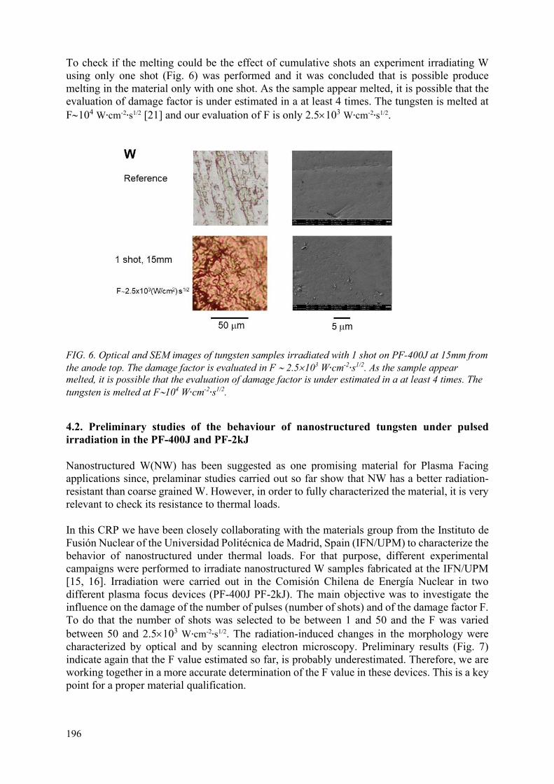
196
To check if the melting could be the effect of cumulative shots an experiment irradiating W using only one shot (Fig. 6) was performed and it was concluded that is possible produce melting in the material only with one shot. As the sample appear melted, it is possible that the evaluation of damage factor is under estimated in a at least 4 times. The tungsten is melted at F104 W∙cm-2∙s1/2 [21] and our evaluation of F is only 2.5103 W∙cm-2∙s1/2.
FIG. 6. Optical and SEM images of tungsten samples irradiated with 1 shot on PF-400J at 15mm from the anode top. The damage factor is evaluated in F 2.5103 W∙cm-2∙s1/2. As the sample appear melted, it is possible that the evaluation of damage factor is under estimated in a at least 4 times. The tungsten is melted at F104 W∙cm-2∙s1/2.
4.2. Preliminary studies of the behaviour of nanostructured tungsten under pulsed irradiation in the PF-400J and PF-2kJ
Nanostructured W(NW) has been suggested as one promising material for Plasma Facing applications since, prelaminar studies carried out so far show that NW has a better radiation-resistant than coarse grained W. However, in order to fully characterized the material, it is very relevant to check its resistance to thermal loads.
In this CRP we have been closely collaborating with the materials group from the Instituto de Fusión Nuclear of the Universidad Politécnica de Madrid, Spain (IFN/UPM) to characterize the behavior of nanostructured under thermal loads. For that purpose, different experimental campaigns were performed to irradiate nanostructured W samples fabricated at the IFN/UPM [15, 16]. Irradiation were carried out in the Comisión Chilena de Energía Nuclear in two different plasma focus devices (PF-400J PF-2kJ). The main objective was to investigate the influence on the damage of the number of pulses (number of shots) and of the damage factor F. To do that the number of shots was selected to be between 1 and 50 and the F was varied between 50 and 2.5103 W∙cm-2∙s1/2. The radiation-induced changes in the morphology were characterized by optical and by scanning electron microscopy. Preliminary results (Fig. 7) indicate again that the F value estimated so far, is probably underestimated. Therefore, we are working together in a more accurate determination of the F value in these devices. This is a key point for a proper material qualification.

197
FIG. 7. (a) Top view images scanning electron microscopy images fora typical nanostructured W sample as deposited; (b) irradiated with a F value of 50 (W/cm2)∙s1/2with one pulse; (b) 5 pulses; (c) 10 pulses.
4.3. Plasma interacting with materials
To complement the studies of plasma facing components for fusion reactors, it is crucial to study the plasma at the moment in which it interacts with the wall material. For this reason, our research program includes studies of the plasma interacting with a target material in front of the anode using optical refractive diagnostics and visible spectroscopy. Preliminary results of the visible spectroscopy of the plasma interacting with a sample were obtained [17]. The experiments were done in the PF-50J discharges in hydrogen, with a Si wafer placed 15mm in front of the anode.
Figure 8 shows the visible spectra at different times after the pinch, of the light emitted from the region between the anode and the sample Si wafer. The z axis is the axial position between the anode top and the sample and the x axis is the wavelength .

198
FIG. 8. Visible spectra at different times for the region between the anode and the sample Si wafer, z axis is the axial position between the anode top and the sample, x axis is the wavelength . At 120 ns after the pinch Si II (Si1+) is observed in the sample region. Also, the H emission is observed from the anode towards the sample. The spectrum close to the sample is shown at left. A Si and hydrogen plasma can be identified at the sample and a hydrogen-only plasma at the anode top. At 145 ns there is a similar emission as seen at 120 ns, but with more dense hydrogen plasma at the sample (inferred from the H line broadening) and hydrogen plasma at middle position between the anode top and sample. At 320 ns on the anode region Fe III (Fe2+), Al II (Al1+), Al III (Al2+), O II (O1+) can be identified. Si II is not observed on the sample region at that time. In addition, a plasma beyond the sample is observed.
The spectroscopy observations are consistent with the hydrogen plasma shock arriving to the sample and ionizing the Si at 120ns. At 145 ns the hydrogen plasma has a higher electron density, compared with plasmas at earlier and later times. At 320 ns a metallic plasma can be identified, leaving the stainless-steel anode region. Emission from Al and O is associated to the interaction of the plasma sheath with the Alumina (Al2O3) insulator sleeve at the anode. 4.4. Stainless steel and molybdenum irradiated on PF-2J The PF-2J repetitive table top pulsed irradiator, described in section 3.1, was used to test SS samples (AISI 304) at different positions from the anode top: 2.8, 3.6 and 5.4 mm producing a damage factor F 104, 103, 102 W∙cm-2∙s1/2 per shot, respectively. At 2.8 mm, i.e. F104 W∙cm-
2∙s1/2 per shot, 1, 10, 100 and 1000 shots were accumulated in SS samples. Thousands of shots were accumulated in 3 to 4 hours. In addition, preliminary results irradiating molybdenum samples with 500 shots at a damage factor F 104 W∙cm-2∙s1/2 were obtained. Figure 9 shows a time integrated photograph of a single discharge in the PF-2J. A material sample is located over the anode.
z
Si sample
anode top
120 ns 320 ns 145 ns

199
FIG. 9. Time integrated photograph of a single discharge in the PF-2J. Plasma can be seen on the top of the anode (anode diameter 2.2 mm). Also, a bright spot is seen in the sample located over de anode due to the axial plasma shock interacting with the sample.
FIG. 10. SS samples (AISI 304) irradiated in the PF-2J at 0.1 Hz with 100 shots, at different positions from the anode top: 2.8, 3.6 and 5.4 mm, producing a damage factor F 104, 103, 102 W∙cm-2∙s1/2per shot, respectively.

200
FIG. 11. SS samples (AISI 304) irradiated in the PF-2J at 0.1 Hz. Samples located at 2.8 mm (F104 W∙cm-2∙s1/2 per shot) with 1, 10, 100 and 1000 shots. Photographs with 1, 10, 100 and 1000 shots from left to right.
FIG. 12. Molybdenum sample irradiated in the PF-2J at 2.8 mm (F 104 W∙cm-2∙s1/2 per shot) at 0.1 Hz with 513 shots. The value for the damage factor to produce melting in stainless steel is F1.3104 W∙cm-2∙s1/2 [22]. In Fig. 10, all of the SS samples (AISI 304) irradiating in the PF-2J at different positions from the anode top: 2.8, 3.6 and 5.4 mm, producing a damage factor F 104, 103, 102 W∙cm-
2∙s1/2 per shot, respectively; present evidence of thermal effects (rings of different grey scale) and melting. From Fig. 11, is possible see that the SS sample (AISI 304) irradiated in the PF-2J with only one shot, present clues of melting. This correspond to a sample located at 2.8 mm from the anode top and an estimated F 104 W∙cm-2∙s1/2. In Fig. 12 in the Molybdenum sample irradiated with 500 shots also thermal effects (rings of different grey scale) and melting are observed. Roughly could be possible say that the Mo irradiated with 500 shots at the same position than the SS, presents similar effects than the observed for the SS irradiated with 10 to 100 shots (see Figs 11–12). Of course, detailed analysis of the irradiated samples is required. In addition, a better calibration of the damage factor for plasma focus devices is required. The

201
determination of the irradiation area is critical and also of the radial dependence of the power flux on the sample. To irradiate different materials with damage factor value known to produce melting, at different positions, would allow a better calibration. 5. THEORETICAL STUDIES AND SIMULATION TOOLS Theoretical studies and computer simulation tools to model the interaction and effects of fusion-relevant pulses on materials and to assist the design of experiments and interpretation of results, have been explored. 5.1. Computer simulation. Classical and ab-initio molecular dynamics simulation On the one hand, microcanonical simulations of melting in two-dimensional solids and study its possible application to radiation-induced melting of surfaces is being performed. On the other hand, a kinetic Monte Carlo simulation and temperature-accelerated dynamics of simple solids under radiation is being implemented. [18, 19].
5.2. Theoretical and simulation studies on damage factor interpretation A model of kinetics of radiation-induced defect concentration based on the master equation, together with a non-equilibrium statistical model of melting and vacancy formation as thermally activated processes was constructed. There are significative advances in the development of a simple model for the accumulation of defects in materials subjected to radiation based on the use of the master equation, that connects the empirical damage factor with the expected fraction of point defects in the material [20]. 6. REMARKS AND CONCLUSIONS Following remarks and conclusions are obtained from the research presented along to this report:
Small plasma focus (1kJ) and table top plasma focus devices (400J and 2J) can work as a plasma source to mimic the irradiation conditions that PFM have to withstand in a nuclear fusion reactor.
The dynamics of the axial plasma shock ejected after the pinch was characterized using pulsed optical refractive diagnostics in the PF-400J. The temporal evolution of the position of the axial plasma shock, and the velocity, kinetic energy, interaction area, interaction time, power flux and damage factor F, for a sample located at different position from the anode top for the PF-400J was obtained.
It was found that the damage factor, F, highly depend of the axial distance of the sample from the anode top. In addition, the damage factor F varies smoothly with the energy of the plasma focus device E, as F E1/6. Thus, a table top PF device of hundreds joules, inclusive a PF of few joules can produce the same damage factor than a larger device of MJ, just adjusting the position of the sample.
Devices with tunable damage factor, F, can be constructed based upon plasma focus devices technology. The table top plasma focus PF-400J, operating at hundred joules, was used as tunable damage factor devices to irradiate materials with plasma shocks. The damage factor F can be tune 103–105 W∙cm-2∙s1/2. However, a better calibration of the damage factor is required.

202
A very small table top PF device working at only 2J was designed and constructed, PF-2J as a tunable damage factor irradiator. The damage factor F can be tune 102–104 W∙cm-2∙s1/2. It was tested using SS samples. Thousand shots are possible to obtain in 3 to 4 hours using the PF-2J at 0.1Hz. However, a better calibration of the damage factor is required in the PF-2J device.
W and nanostructured W provided by the Instituto de Fusión Nuclear (IFN) of Madrid, Spain, were irradiated with the small PF-2kJ operating at 1kJ and with the table top PF-400J. After irradiation, the samples were analysed in collaboration with IFN, Madrid, Spain.
Preliminary results on Mo were obtained using the PF-2J at 0.1Hz as irradiator. Preliminary spectroscopy results of the plasma shock interacting with samples were
obtained. Molecular dynamics simulations to complement the experimental studies were
implemented. A theoretical approach to understand the meaning of the damage factor was done. A better calibration of the damage factor for plasma focus devices is required. The
determination of the irradiation area is critical and also of the radial dependence of the power flux on the sample.
The capabilities to study the effects of pulsed radiation relevant to fusion material reactors were implemented in Chile. Including: table top irradiators based on plasma focus technology, optical plasma diagnostics, computational simulation and theoretical approach, and material characterization (in collaboration with the Insituto de Fusión Nuclear, UPM, Madrid, Spain).
ACKNOWLEDGEMENTS
Supported by CRP IAEA contract 20370, CONICYT/Anillo ACT-172101 and FONDECYT 1151471 Chile grants.
REFERENCES
[1] SOTO, L., Plasma Phys. and Control. Fusion 47 (2005). [2] SOTO, L., PAVEZ, C., TARIFEÑO, A., MORENO, J., VELOSO, F., Plasma Sources Sci.
and Technol. 19 (2010) 055017. [3] BERNARD, A., BRUZZONE, H., CHOI, P., et al., Moscow Phys. Soc. 8 (1998) 93. [4] SILVA, P., et al., Applied Physics Letters 83 (2003). [5] SOTO, L., et al., J. Phys. D: Appl. Phys. 41 (2008) 205215. [6] SOTO, L., et al., Physics of Plasmas 24 (2017) 082703. [7] SOTO, L., et al., Physics of Plasmas 21 (2014) 122703. [8] PAVEZ, C., PEDREROS, J., TARIFEÑO-SALDIVIA, A., SOTO, L., Physics of Plasmas
22 (2015) 040705. [9] SOTO, L., PAVEZ, C., CASTILLO, F., VELOSO, F., MORENO, J., AULUCK, S.K.H.,
Physics of Plasmas 21 (2014) 072702. [10] INESTROSA-IZURIETA, M.J., RAMOS-MOORE E., SOTO, L., Nuclear Fusion 55
(2015) 093011. [11] ZEL’DOVICH, Y., RAIZER, Y., Physics of shock waves and high temperature
phenomena, Dover Publications Inc, New York (2002). [12] SOTO, L., ZANELLI, D., DAVIS, S., AVARIA, G., BORA, B., JAIN, J., MORENO,
J., PAVEZ, C., “Table top plasma focus as tunable pulsed irradiator to study materials for fusion energy reactors”, Simposio de Nanotecnología (Proc. Int. Conf. Santiago, 2018).

203
[13] ZANELLI, D., DAVIS, S., AVARIA, G., BORA, B., JAIN, J., MORENO, J., PAVEZ, C., SOTO, L., “Statistical Study and Reliability Analysis in a Portable Plasma Focus Device”, 19th International Congress on Plasma Physics, (Proc. Int. Conf. Vancouver, 2018).
[14] SOTO, L., ZANELLI, D., DAVIS, S., AVARIA, G., BORA, B., JAIN, J., MORENO, J., PAVEZ, C., “Reliability Study and Statistical Analysis in a Portable Plasma Focus Device: An unavoidable characterization for applications”, Annual Meeting of the International Center of Dense Magnetized Plasmas (Proc. Int. Conf. Warsaw, 2018).
[15] GONZALEZ-ARRABAL, R., et al., 10th International Conference on Inertial Fusion Sciences and Applications (Proc. Int. Conf. Saint Malo, 2017).
[16] PANIZO, M., et al., “Behavior of nanostructured and coarse grained tungsten under pulsed irradiation: hydrogen and thermal loads”, 8th IAEA Technical Meeting on the Physics and Technology of Inertial Fusion Energy Targets and Chambers, Tashkent, Uzbekistan, 8-9 March 2018.
[17] SOTO, L., et al., “Recent findings in fusion studies using table top and miniaturized dense plasma focus devices operating from hundred joules to less than one Joule” IAEA Fusion Energy Conference 2018 (Proc. Int. Conf. Ahmedabad, 2018).
[18] GUTIÉRREZ, G., DAVIS, S., PALMA, G., Configurational temperature in constrained systems: the case of spin dynamics, Journal of Physics A: Mathematical and Theoretical 51 (2018) 455003.
[19] DAVIS, S., LOYOLA, C., PERALTA, J., Bayesian statistical modelling of microcanonical melting times at the superheated regime, Physica A 515 (2019) 546-557.
[20] DAVIS, S., AVARIA, G., BORA, B., JAIN, J., MORENO, J., PAVEZ, C., SOTO, L., “A simple model of accumulation of point defects in materials exposed to radiation”, Simposio de Nanotecnología (Proc. Int. Conf. Santiago, 2018).
[21] LINKE, J., ESCOURBIAC, F., MAZUL, I.V., NYGREN, R., RÖDIG, M., SCHLOSSER, J., SUZUKI, S., J. Nucl. Mater. 367–370 (2017) 1422.
[22] KLIMOV, N.S., et al., Plasma facing materials performance under ITER-relevant mitigated disruption photonic heat loads, J. Nucl. Mater. 463 (2015) 61.
[23] PAVEZ, C., SOTO, L., Scaling and stabilization due to the large ion Larmor radius (LLR) effects in plasma focus devices, Phys. Scr. T131 (2008) 014030.

204
PHYSICS AND TARGET DESIGN FOR SHOCK IGNITION SCENARIO OF AN INERTIAL CONFINEMENT FUSION POWER PLANT V.T. TIKHONCHUK Centre Lasers Intenses et Applications, University of Bordeaux – CNRS – CEA, Talence, France ELI-Beamlines, Institute of Physics, Czech Academy of Sciences, Dolní Břežany, Czech Republic Email: [email protected] Abstract
The paper presents a short review of activities conducted in France in collaboration with other European groups and dedicated to characterization of laser-target interaction under the condition of shock ignition scheme of inertial confinement fusion. This work has been coordinated by the CELIA laboratory of the University of Bordeaux in the framework of the Coordinated Research Project “Pathways to Energy from Inertial Fusion: Materials beyond Ignition”.
1. INTRODUCTION
The French contribution to the Coordinated Research Project on “Pathways to Energy from Inertial Fusion: Materials beyond Ignition” consists in the physics analysis of the conditions needed for realization of Shock Ignition Scenario of an Inertial Confinement Fusion (ICF) Power Plant. The Shock Ignition is the most promising approach to ICF in the direct drive configuration allowing for a relatively simple target design, relaxed requirements on the laser energy and irradiation symmetry and high energy gain. However, Shock Ignition operates at high laser intensities 1015–1016 W/cm2 where non-linear processes need to be well understood and controlled. Consequently, we conducted a series of theoretical studies, numerical simulations and experiments aiming on characterization and control of such effects as: (i) strong shock generation, (ii) hot electron production and transport, (iii) laser imprint smoothing and (iv) optimized fusion target design.
“Along with the ongoing research in conventional inertial confinement fusion, over the last two decades an increasing interest in alternative inertial fusion schemes [1] which are promising either a lower ignition threshold, a more stable implosion, or a higher energy gain needed for industrial applications. ICF considers at present a deuterium–tritium (DT) mix as a fuel because it is easiest to ignite. This process consists of three stages [2]: (i) implosion of DT fuel to densities of a few hundred g per cm3 with a laser; (ii) heating a small portion of a compressed fuel to the temperature about 5–7 keV where the fusion reactions are ignited; and (iii) release of the major part of the fusion energy in the combustion wave propagating from the ignition spot through the cold fuel. In order to self-heat, the ignition region needs to trap some of the fusion burn products. For a DT mixture these are mainly α-particles. At 10 keV plasma temperature these have a range of about 0.3 g/cm2. Therefore, ignition requires that the hotspot region needs to have simultaneously at least this column density and the 5 keV temperature.
Near term ignition attempts use lasers with the energy of 1–2 MJ driving capsules with radii of about 1 mm and a mass of 1 mg [3]. Of this only 5 kJ is coupled to the hotspot in the indirect drive scheme” [1]. The direct drive scheme allows to couple at least 4 times more energy to the hotspot. Alternative ignition schemes such as Fast Ignition and Shock Ignition could further increase the energy coupling and thus the fusion energy gain in expense of a more complicated physics of laser plasma interaction. Laser driven implosion is the only known way to achieve
205
the pressure and density in the hotspot needed for ignition. The “fuel shell is accelerated over some distance to a given implosion velocity. The absorbed laser energy is stored as the kinetic energy of the shell, which is then converted to internal energy on stagnation. Efficient conversion of this kinetic energy into internal energy of a compressed fuel requires good drive symmetry so the imploding shell preserves its integrity and does not mix with the hotspot material. In addition, the implosion concentrates the shell energy into a small fraction of its mass when it comes to stagnation” [1]. The typical implosion velocity required for ignition in the conventional ICF schemes is on the order of 300–400 km/s. Shells at such velocities are very fragile and could be easily destroyed due to the development of hydrodynamic Rayleigh-Taylor instability. The alternative ignition schemes operate at lower implosion velocities where the shells are more stable and the additional energy into the hotspot is brought with energetic particles or a strong shock. Consequently, they require higher laser intensities and a more precise synchronization of the laser pulses.
The “shock ignition scheme aims for a demonstration of high gain inertial confinement fusion on existing laser facilities [4, 5]. This is the most conventional of the alternative approaches. It considers the laser intensities 10–30 times higher than the conventional direct drive, but only later in time after the shell has partially converged. This enables a more stable implosion thanks to a relatively low implosion velocity below 300 km∙s-1, and, at the same time, avoids the undesirable effect of fuel preheat by fast electrons” [1]. It implies generation of the ablation pressure of more than 300 Mbar for producing a strong converging shock. Laser plasma interaction at the corresponding laser intensities 1015–1016 W∙cm-2 is strongly nonlinear and needs a special analysis.
This paper presents the results of research on Shock Ignition obtained in the period 2016 – 2018. These activities have been conducted by the researchers of CELIA in strong collaboration with other national and European laboratories and in a broader international context.
2. MODELLING OF LASER-PLASMA INTERACTION AND DEVELOPMENT OF ADVANCED NUMERICAL TOOLS
The “plasma and laser parameters needed for formation of the ignition shock are in a “dangerous” zone where the nonlinear effects in laser–plasma interaction manifest themselves in enhanced scattering and generation of energetic electrons. The laser intensities above 1015 W/cm2 demonstrate increasing reflectivity levels related to the Stimulated Raman Scattering (SRS) and Stimulated Brillouin Scattering (SBS), laser beam filamentation (FI), two-plasmon instability (TPD) and other parametric processes. All these effects are not included in standard versions of hydrodynamic codes and thus may be easily underestimated or overlooked. Moreover, this range of laser intensities was not studied experimentally in detail. Only recently correlations between the hot-electron production and SRS have been reported in the experiments. The specificity of the shock-ignition scheme may allow one to mitigate undesirable nonlinear effects and even to benefit from their presence. In difference from the standard implosion schemes, the shock-ignition target is accelerated for a longer time at lower intensities, so that, at the moment of intense ignition spike arrival the shell radius is reduced by a factor of two. It is already compressed and its areal density is increased by a factor of ten or twenty approaches a level of about 10 mg/cm2. This value is comparable to the stopping range of 100 keV electrons. For this reason, the electrons generated in the corona with lower energies may not present a danger for the fuel compression. They may be even beneficial” [6,7] for increase the shock pressure while depositing their energy at the outer shell surface. A review of

206
recent theoretical developments concerning the physics of laser plasma energy depositions and hot electron transport is presented in Ref. [8].
2.1. Strong shock generation in a spherical geometry
Characterization of hot electron generation under the Shock Ignition conditions has been performed experimentally in the convergent and planar geometries. In the experiments on the OMEGA facility [9, 10] a spherical plastic target doped with Ti and covered with a thin ablator layer has been irradiated with 60 laser beams at third harmonic (351 nm) with total energy ~25 kJ and average intensity up to 5×10¹⁵ W/cm2. Four different ablators (CH, C, Be and SiO2) and two irradiation conditions (with and without laser temporal smoothing) have been explored. The number of hot electrons and their effective temperature have been measured by detecting the characteristic K-α and bremsstrahlung emissions from the dopant. The shock strength was calculated with a radiation hydrodynamic code by knowing the time of the shock collapse to the target centre manifested by a short X ray flash.
FIG. 1. (a) X ray flash time for different ablators with smoothing by spectral dispersion (SSD) on (squares, blue) and SSD off (circles, red); (b) measured time integrated conversion efficiency (CE) of laser energy into hot-electron energy. Reprinted from [9] with permission from the American Institute of Physics.
Figure 1 shows the shock collapse time and the laser energy fraction transmitted to hot electrons in experiments with different ablators [9]. Anti-correlation between these two parameters indicates clearly a positive contribution of hot electrons to the shock wave velocity and consequently to the shock wave amplitude. These hot electrons are accelerated in the electron plasma waves produced in the Stimulated Raman Scattering (SRS) and have average energy of 40 – 50 keV. Moreover, by turning off temporal laser beam smoothing one can further increase the hot electron production up to 9% in the plastic ablator and the shock speed. The higher conversion efficiency in CH is attributed to stronger damping of ion-acoustic waves because of the presence of light H ions. The saturation level of electron plasma waves in SRS is controlled by their secondary parametric decay in oppositely travelling electron plasma wave and in ion-acoustic wave. The threshold of the parametric decay is proportional to the ion-acoustic damping rate. In the case of a high ion-acoustic damping provided by hydrogen ions, the threshold of the parametric decay is higher and the electron plasma waves can grow to a higher level, producing a stronger SRS signal and a larger number of hot electrons.

207
FIG. 2. (a) Evolution of the shock (red) and ablation (black) pressure for the case without hot electrons; (b) with hot electrons. Reprinted from [9] with permission from the American Institute of Physics.
Experiments on strong shock excitation in spherical plastic targets were interpreted with the radiation–hydrodynamics code CHIC developed at CELIA [10]. The laser-energy deposition is described by a two-dimensional ray-tracing model based on the paraxial complex geometrical optics (PCGO) and providing access to the laser intensity in any location in plasma [11]. In addition to the collisional inverse bremsstrahlung absorption, it accounts for such non-collisional effects as resonance absorption, excitation of parametric instabilities SRS and TPD, cross beam energy transfer and hot-electron generation. Figure 2 shows temporal evolution of the ablation and shock pressures in two simulations with and without hot electrons. These simulations can be assimilated to the experiments without and with laser temporal smoothing, respectively. Ablation pressure raises to approximately 130 Mbar in both cases during the interval between 1 and 2 ns, when the main laser pulse arrives. In contrast, hot electrons in the case b) deposit their energy downstream the shock thus doubling its pressure to approximately 270 Mbar. The CHIC simulations successfully reproduced the shock collapse time, the laser pulse absorption and the fraction of hot electrons. That confirms the validity of the numerical model and the ability of hot electrons to boost the shock pressure to the level needed for Shock Ignition.
The experiment [10] demonstrated however, that a small fraction of hot electrons ~1% penetrates upstream the shock front and deposits their energy in the target centre thus preheating the target material and reducing the shock strength. This is undesirable effect which may impose more stringent conditions on the Shock Ignition. It is demonstrated in Ref. [12] that the target design proposed several years ago [4] is not protecting the fuel from the hot electron preheat and the target fails to ignite. A new shock ignition design has been proposed in Ref. [13] for the NIF conditions. It uses a thicker ablator allowing a more efficient hot electron stopping, lower fuel preheat and higher fusion yield.
2.2. Strong shock generation in the planar experiments
Unfortunately, experiments conducted on OMEGA are limited in laser energy and in intensity. They do not allow to explore all range of parameters of interest for Shock Ignition. Experiments with higher intensities are conducted in a planar geometry on several laser facilities in Europe with a goal to achieve the highest possible shock pressure and to measure the hot electron characteristics. Experiments in France on the LIL laser where conducted with planar and hemi-spherical targets at third harmonic (351 nm) with the laser energy of 10 kJ [14]. The shock pressure was deduced from the measurements of the shock velocity with the VISAR diagnostics and shock breakout time with an optical pyrometer. Contribution of parametric instabilities to laser absorption was rather small because of laser intensity was limited to 1.5×10¹⁵ W/cm2. The

208
shock dynamics was successfully reproduced in the radiation hydrodynamic simulations with CHIC providing the shock pressure of 90 Mbar in a planar target. Hemispherical target provides shock focusing and reduced lateral losses. It allowed to increase the maximum pressure to 120 Mbar.
Planar experiments at a higher laser energy of 70 kJ are planned in 2019 on the LMJ laser facility [15]. By using specially designed phase plates we are planning to increase the laser intensity on target to (8–9)×1015 W∙cm-2 and to attain the conditions pertinent for Shock Ignition. The shock pressure is expected to be 220 Mbar with a significant contribution of hot electrons. The experimental scheme is shown in Fig. 3. Three LMJ quadruplets will be interacting in the focal plane and the fourth quadruplet will be used for the side-on shock radiography. A 3 ns laser prepulse will create an appropriate plasma density profile and a 1.2 ns main pulse with drive the shock. The target contains three imbedded thin metallic layers. Their characteristic X ray emission will provide information on the number and energy distribution of hot electrons. Because of oblique incidence of laser beams, we expect to observe the effect of cross beam energy transfer. Figure 3(c) shows the expected distribution of the plasma pressure across the focal spot.
FIG. 3. (a) Scheme of the LMJ experiment on strong shock excitation with three quadruplets – two coming from the North and one from the South; (b)temporal shape of the laser pulse on the target with a 3 ns prepulse and 1.2 ns main pulse. (c) Pressure distribution on the target after the arrival of the main pulse. Reproduced with permission from Ref. [15].
Experiments on a smaller level of laser energy but with a tighter beam focusing were conducted on the PALS laser facility in the Czech Republic. This iodine laser delivers up to 700 J at the first harmonic (1314 nm) or up to 350 J at the third harmonic (438 nm) in a 300 ps pulse duration. By tightly focusing this pulse on a target in a 100 µm spot one may attain intensities exceeding 2×10¹⁶ W∙cm-2 at the first harmonic and 6×10¹⁵ W∙cm-2 at the third harmonic. Multi-layered targets with two imbedded metallic tracer layers allowed us “to simultaneously study the generation of a strong shock and the production of hot electrons. Phase plates used at both irradiation wavelengths provided a uniform and well-known intensity profile”4. The auxiliary laser beam, with energy up to 80 J at first harmonic was used to create a plasma corona with a relatively long axial scale-length and a flat radial density distribution.
Results presented in Refs. [16, 17] characterize the laser plasma interaction and hot electron production at the third harmonic. Paper [18] presents a comparison of the shock drive
4 Batani, D., et al., Progress in understanding the role of hot electrons for the shock ignition approach to inertial confinement fusion, Nuclear Fusion 59 (2019) 032012.

209
performance on the first and third harmonics. Laser target interaction at 3ω is essentially collisional. Collision-less processes contribute about 2.3% to the laser absorption and hot electrons with energy about 20 keV carry less than 1% of the absorbed energy. In contrast, the hot electron energy in the experiments at 1ω is more than 40 keV and they carry more than 5% of the absorbed energy. The shock pressure at the laser intensity of 1016 W∙cm-2 was evaluated from the measured shock breakout time to be 90 Mbar. This pressure is much less than the one expected from the one dimensional scaling law on the order of 200 Mbar because of strong lateral energy losses. The size of the laser focal spot is comparable to the standoff distance between the laser absorption zone and the ablation layer. “Generally, we found a good agreement between the results obtained by advanced hydrodynamics simulations with experimental results in the UV domain of laser wavelengths”4 (438 nm). The experimental results the case of 1ω irradiation, do not fully agree with the prediction of the CHIC-PCGO simulations. This discrepancy indicates the necessity of improving the parametrization of the nonlinear laser plasma interactions in the IR domain. The correspondent numerical simulations are ongoing. They will allow to improve the performance of existent numerical tools.
3. THEORETICAL MODEL OF HOT ELECTRON TRANSPORT
An important issue for ICF is the electron energy transport. The mean free path of electrons in the laser heated corona is comparable with the distance of the conduction layer, so the standard diffusion model of electron transport is not valid. The most advanced version of a nonlocal electron transport model which was proposed in Ref. [19], has been tested recently in detailed kinetic simulations with Fokker-Planck and Particle-in-Cell codes [20,21]. Although it is validated in a broad range of parameters relevant to ICF for the cases without magnetic field, its extension to magnetized plasmas is still pending. Another, more performant reduced kinetic model has been developed in Ref. [22]. It is based on the entropic closer of the angular momentum series and allows a straightforward extension of the model to the case where magnetic fields are present [23].
Figure 4 shows a comparison of the performance of nonlocal kinetic models with full scale kinetic simulations. It is performed for a simple but representative case of a plasma of a constant density and a temperature decreasing from a high value of 1 keV on the left to a low level of 0.1 keV on the right over a jump of variable thickness.
FIG. 4. Comparison of the nonlocal models of electron transport SNB [19] and AP1 [21] with the full kinetic simulations performed with the Fokker-Planck codes ALADIN and IMPACT and a Particle-in-Cell code CALDER. (a) Dependence of the suppression of the heat conductivity coefficient on the Knudsen number, Kn, which is ratio of the electron mean free path to the temperature gradient scale length; (b) spatial distribution of the electron heat flux along the temperature profile (blue dashed line) for the case Kn = 0.01; (c) anisotropic part of the electron distribution function calculated with

210
reduced and full kinetic models at the position z = 450 µm (blue point in the panel b). Reproduced with permission from Ref. [21].
The ratio of the electron mean free path to the jump thickness is the Knudsen number Kn. In the limit of very small Kn the electron heat flux Q is described by a diffusion equation Q=-κSH∇T, where κSH is the well-known diffusion coefficient calculated by Spitzer and Härm. Figure 4a shows that the reduced model AP1 successfully describes the heat flux reduction up to Kn ~ 0.1, but it fails at stronger temperature gradients. Similar behavior has been observed also in Ref. [20] for the SNB model [19] and it is explained by increasing error in evaluation of the return current. Higher values of the Knudsen number could be accessible for nonlocal models under the condition that the electric field driven by the return current would be correctly evaluated. This problem is not yet resolved for the moment.
Figure 4(b) shows spatial distribution of the electron heat flux for the case Kn = 0.01 shown in panel a. The heat flux distribution is significantly different from the Spitzer-Härm theory shown in black dashed line, and both nonlocal models succeed to reproduce correctly flux suppression in the zone of maximum temperature gradient (blue point at z = 450 µm) and flux increase in the cold plasma (blue point at z = 600 µm). There is however, a significant difference between the SNB and AP1 models in the shape of the electron distribution function. The distribution function calculated within the SNB model (which is based on the BGK collision integral) differs from the full kinetic calculations, while the AP1 model based on a more advanced collision integral derived by Albritton et al. [21, 23] shows much better agreement. This work shows possibility of further improvement of the nonlocal electron plasma transport description in hydrodynamic codes by extending the AP1 model to the cases of stronger nonlocality and external magnetic fields.
4. CONTROL OF THE LASER IMPRINT AND EXCITATION OF HYDRODYNAMIC INSTABLITIES
Laser imprint is one of sources of initial perturbations leading to development of hydrodynamic instabilities in the direct drive ICF. It takes place at the initial part of the laser pulse when the thickness of conduction zone is small and laser intensity fluctuations may induce pressure perturbations directly at the ablation surface. Temporal laser beam smoothing is not operational either at the first few hundred picoseconds, so one has to find other ways to overcome the problem of laser imprint. Thermal smoothing consists in creating a sufficiently large conduction zone before the laser reaches the ablator. Low density foams placed at the outer surface of ablator may be used for that purpose, but they need to be ionized and homogenized before the laser pressure has access to the ablation surface. It can be achieved either by a short X ray flash or by a laser-driven supersonic ionization wave. The latter method is preferential as it does not preheat the fuel and the foam plasma is swiftly homogenized because of a high plasma temperature, but the underdense foams are fragile and difficult to fabricate.

211
FIG. 5. (a) Scheme of the OMEGA experiment on laser imprint suppression: a plastic foil is covered with a low density foam (light blue) and irradiated with laser beam imprinting a structure with a period 30 or 60 µm. The face-on radiography is performed with a back lighter source (left). (b) X ray radiographs of a bare CH target, and targets covered with 7 mg∙cm-3 and 5 mg cm-3 foams of 500 µm thickness. The periodic structure is imprinted with a 60 µm phase plate. The radiographs are taken at 1.2, 1.5, and 1.8 ns. (c) Comparison between the experimental data and numerical simulations for a bare CH target (red) and the one coved with a 7 mg∙cm-3 foam (blue). Simulations are represented by the solid lines and points represent the experimental data. Reproduced with permission from Ref. [25].
We demonstrated in Ref. [25] “for the first time the imprint mitigation mechanism induced by underdense foams by measuring target areal density modulations amplified” [25] by the Richtmyer-Meshkov and ablative Rayleigh-Taylor (RT) instability. The reduction of the intensity fluctuations is observed and explained by the “forward stimulated Brillouin scattering (FSBS). The processes of laser beam smoothing in the foam plasma and the RT instability growth in the foil are simulated with a chain of dedicated multi-dimensional numerical tools” [25]. Figure 5(a) shows the experimental setup and the major diagnostics. The “targets were made of 15 µm-thick CH foils which are sufficiently thin to be accelerated during a 2 ns laser pulse” [25]. Some targets were covered with a 500 µm thick low density foam supported by a copper washer. The foam density was below the critical density for the laser light, thus permitting a supersonic foam ionization. One of the laser beams was equipped with a phase plate producing intensity modulations with a 30 or 60 µm period. The “laser intensity was adjusted in order to ensure the same foil acceleration in the shots with and without foam” [25]. Radiographies of shots performed with a 60 µm imprint are presented in Fig. 5b for the bare CH foil, and the targets covered with 7 and 5 mg cm-3 foams. Compared to the bare CH target, addition of a foam layer results in a significant reduction of the modulation amplitude. The best results were obtained with a 7 mg cm-3 foam, while a 5 mg cm-3 foam produced undesirable three dimensional structures. Figure 5c shows a comparison of the temporal evolution of the periodic modulations imprinted on a CH target measured in experiment and calculated with the radiation hydrodynamics code CHIC. A significant delay in the RT instability development by a time of 1 ns is rather evident. It is explained by the laser beam temporal smoothing induced by forward stimulated Brillouin scattering of the laser beams propagating through the under dense foam plasma. Numerical simulations with a paraxial code PARAX and experiments show a similar level of imprint reduction of a factor of 2-3 with the 7 mg cm-3 foam coated targets. This remarkable result confirms an efficiency of using the low density foams for laser temporal smoothing and imprint reduction.
Studies of the excitation control and nonlinear development of RT instability have been continued to the NIF laser within the open access program Discovery Science. 60 times higher laser energy available on NIF has allowed us to extend the laser pulse duration to 30 ns and

212
observe for the first time a strongly nonlinear evolution of RT driven density perturbations in the geometry similar to the one shown in Fig. 5a. Preliminary results related to acceleration of a bare CH target are presented in Refs. [26,27]. A more detailed analysis of the NIF results are presented in the Ph.D. thesis manuscript [28] defended by C. Mailliet.
5. NETWORKING THE EUROPEAN ICF COMMUNITY
This work has been conducted in close collaboration with many national, European and international partners providing theoretical and numerical support and an access to high energy laser facilities worldwide. In particular, we acknowledge a support from the group led by J. Honrubia from the Polytechnic University of Madrid in the improved design of reactor size targets for the Shock Ignition scheme. This work is also supported by the research projects supported by the EUROfusion Consortium in the framework of three research projects: “Towards Demonstration of Inertial Fusion for Energy” (ENR-IFE15-CEA-02) for the period 2014–2018, “Non-local thermal transport in inertial and magnetic confinement fusion plasmas” (CfP-AWP17-IFE-CCFE-01) for the period 2017–2018, and “Preparation and Realization of European Shock Ignition Experiments” (CfP-AWP17-IFE-CELIA-02) for the period 2017 – 2018. These projects allowed us to coordinate the research work between the collaborating European laboratories and to field experiments on the OMEGA facility at the University of Rochester at the USA.
The collaboration has facilitated by the annual workshops Direct Drive and Fast Ignition Workshop, organized in April 2016 in Bordeaux, France, in March 2017 in Salamanca, Spain, and in March 2018 in York, UK. They gathered scientists from all collaborating European laboratories with participation for scientists from Japan and USA. The collaboration is also benefited from the ERASMUS PLUS – KA2 programme “Innovative Education and Training in high power laser plasmas" (PowerLaPs). That project joins 8 European universities (Technological Educational Institute of Crete, Queens University Belfast, University of Bordeaux, Czech Technical University in Prague, Ecole Polytechnique, University of Ioannina, University of Salamanca and University of York) for the two year period, 2017 - 2019 and aims to assist and enhance the studies of final year Bachelor students, Masters and PhD students by improving their employability skills in the scientific area of Plasma Physics and High Power Lasers. More than 30 students from all participating universities benefited from joined training sessions related to different topics in inertial fusion energy.
6. CONCLUSIONS
The Coordinated Research Project “Pathways to Energy from Inertial Fusion: Materials beyond Ignition” provided an efficient framework for establishing collaboration links and accelerating research in energy production with laser driven fusion reactions. In particular, the research agreement “Physics and target design for shock ignition scenario of an ICF power plant” enabled a coordination and collaboration on development of more efficient numerical tools, physical model and large scale experiments dedicated to the target design for the fusion energy production with Shock Ignition ICF scheme. The modules describing the non-collisional laser energy absorption in plasma, hot electron generation and nonlocal electron energy transport are revised and improved thus providing a more accurate representation of the physics of laser plasma interaction at high laser intensities relevant for the Shock Ignition scheme. These modules are validated in large scale laser-target experiments. Record shock pressures are obtained: about 300 Mbar in the spherical geometry and 120 Mbar in the planar geometry. An experiment aiming on achieving a shock pressure of more than 200 Mbar in the planar geometry
213
is planned in spring 2019. The laser imprint reduction with low density foam layers is demonstrated on the OMEGA laser facility and a nonlinear evolution of the ablative Rayleigh-Taylor instability is studied for the first time on the NIF at the energy level of 500 – 600 kJ. Good agreement between the experimental results and dedicated numerical simulations opens perspectives for reliable design of the reactor size targets.
ACKNOWLEDGEMENTS
This work has been carried out within the framework of the EUROfusion Consortium and has received funding from the Euratom research and training programme 2014-2018 under grant agreement No 633053. The views and opinions expressed herein do not necessarily reflect those of the European Commission. This work was partially supported by the project ELITAS (ELI Tools for Advanced Simulation) CZ.02.1.01/0.0/0.0/16_013/0001793 from the European Regional Development Fund. This study has been carried out with financial support from the French State, managed by the French National Research Agency (ANR) in the frame of “the Investments for the future” Programme IdEx Bordeaux – LAPHIA (ANR-10-IDEX-03-02).
REFERENCES
[1] TABAK, A., NORREYS, P., TIKHONCHUK, V.T., TANAKA, K.A., Alternative ignition schemes in inertial confinement fusion, Nuclear Fusion 54 (2014) 054001.
[2] ATZENI S. and MEYER-TER-VEHN J., The Physics of Inertial Fusion, Clarendon Oxford (2004). [3] BETTI, R. and HURRICANE, O.A., Inertial confinement fusion with lasers, Nature Phys. 12 (2016)
435. [4] ATZENI, S., RIBEYRE, X., SCHURTZ, G., SCHMITT, A.J., CANAUD, B., BETTI, R.,
PERKINS, L.J., Shock ignition of thermonuclear fuel: principles and modelling, Nuclear Fusion 54 (2014) 054008.
[5] BATANI, D., BATON, S., CASNER, A., DEPIERREUX, S., HOHENBERGER, M., KLIMO, O., KOENIG, M., LABAUNE, C., RIBEYRE, X., ROUSSEAUX, C., SCHURTZ, G., THEOBALD, W., TIKHONCHUK, V.T., Physics issues for shock ignition, Nuclear Fusion 54 (2014) 054009.
[6] THEOBALD, W., NORA, R., SEKA, W., LAFON, M., ANDERSON, K.S., HOHENBERGER, M., MARSHALL, F.J., MICHEL, D.T., SOLODOV, A.A., STOECKL, C., EDGELL, D.H., YAAKOBI, B., CASNER, A., REVERDIN, C., RIBEYRE, X., SHVYDKY,A., VALLET, A., PEEBLES, J., WEI, M.S., BETTI R., Spherical strong-shock generation for shock-ignition inertial fusion, Phys. Plasmas 22 (2015) 056310.
[7] NORA, R., THEOBALD, W., BETTI, R., MARSHALL, F.J., MICHEL, D.T., SEKA, W., YAAKOBI, B., LAFON, M., STOECKL, C., DELETTREZ, J., SOLODOV, A.A., CASNER, A., REVERDIN, C., RIBEYRE, X., VALLET, A., PEEBLES, J., BEG, F.N., WEI, M.S., Gigabar spherical shock generation on the OMEGA laser, Phys. Rev. Lett. 114 (2015) 045001.
[8] TIKHONCHUK V.T., Physics of laser plasma interaction and particle transport in the context of inertial confinement fusion, Nuclear Fusion 59 (2019) 032001.
[9] THEOBALD, W., BOSE, A., YAN, R., BETTI, R., LAFON, M., MANGINO, D., CHRISTOPHERSON, A., STOECKL, C., SEKA, W., SHANG, W., MICHEL, D.T., REN, C., NORA, R.C., CASNER, A., PEEBLES, J., BEG, F.N., RIBEYRE, X., LLOR-AISA, E., COLAÏTIS, A., TIKHONCHUK, V., WEI, M. S., Enhanced hot-electron production and strong-shock generation in hydrogen rich ablators, Phys. Plasmas 24 (2017) 120702.
[10] LLOR AISA, E., RIBEYRE, X., DUCHATEAU, G., NGUYEN-BUI, T., TIKHONCHUK, V.T., COLAITIS, A., BETTI, R., BOSE, A., THEOBALD, W., The role of hot electrons in the dynamics of a laser-driven strong converging shock, Phys. Plasmas 24 (2017) 112711.
[11] COLAÏTIS, A., DUCHATEAU, G., RIBEYRE, X., MAHEUT, Y., BOUTOUX, G., ANTONELLI, L., NICOLAÏ, PH., BATANI, D., TIKHONCHUK, V., Coupled hydrodynamic model for laser-plasma interaction and hot electron generation, Phys. Rev. E 92 (2015) 041101.

214
[12] COLAÏTIS, A., RIBEYRE, X., LE BEL, E., DUCHATEAU, G., NICOLAÏ, TIKHONCHUK, V., Influence of laser induced hot electrons on the threshold for shock ignition of fusion reactions, Phys. Plasmas 23 (2016) 072703.
[13] SHANG, W.L., BETTI, R., HU, S.X., WOO, K., HAO, L., REN, C., CHRISTOPHERSON, A.R., BOSE, A., THEOBALD, W., Electron shock ignition of inertial fusion targets, Phys. Rev. Lett. 119 (2017) 195001.
[14] BATON, S.D., LE BEL, E., BRYGOO, S., RIBEYRE, X., ROUSSEAUX, C., BREIL, J., KOENIG, M., BATANI, D., RAFFESTIN D., Shock generation comparison with planar and hemispherical targets in shock ignition relevant experiment, Phys. Plasmas 24 (2017) 092708.
[15] BATON S., Effect of hot electrons on strong shock generation in the context of shock ignition, LMJ-PETAL User Meeting, Le Barp, 4 October 2018.
[16] CRISTOFORETTI, G., COLAÏTIS, A., ANTONELLI, L., ATZENI, S., BAFFIGI, F., BATANI, D., BARVATO, F., BOUTOUX, G., DUDZAK, R., KOESTER, P., KROUSKY, E., LABATE, L., NICOLAÏ, PH.,.RENNER, O., SKORIC, M., TIKHONCHUK, V., GIZZI, L., Experimental observation of parametric instabilities at laser intensities relevant for shock ignition, EPL 117 (2017) 35001.
[17] CRISTOFORETTI, G., ANTONELLI, L., ATZENI, S., BAFFIGI, F., BARBATO, F., BATANI, D., BOUTOUX, G., COLAITIS, A., SMID, M., STRAKA, P., GIZZI, L.A., Measurements of parametric instabilities at laser intensities relevant to strong shock generation, Phys. Plasmas 24 (2018) 012702.
[18] BATANI, D., ANTONELLI, L., BARBATO, F., BOUTOUX, G. COLAÏTIS, A., FEUGEAS, J.-L., FOLPINI, G., MANCELLI, D., NICOLAI, PH., SANTOS, J., TRELA, J., TIKHONCHUK, V., BADZIAK, J., CHODUKOWSKI, T., JAKUBOWSKA, K., KALINOWSKA, Z., PISARCZYK, T., ROSINSKI, M., SAWICKA, M., BAFFIGI, F., CRISTOFORETTI, G., D’AMATO, F., KOESTER, P, GIZZI, L.A., VICIANI, S., ATZENI, S., SCIAVI, A., SKORIC, M., GUS’KOV, S., HONRUBIA, J., LIMPOUCH, J., KLIMO, O., SKALA, J, GU, Y.J., KROUSKY, E., RENNER, O., SMID, M., WEBER, S. DUDZAK, R., KRUS, M., ULLSCHMIED, J., Progress in understanding the role of hot electrons for the shock ignition approach to inertial confinement fusion, Nuclear Fusion 59 (2019) 032012.
[19] SCHURTZ, G.P., NICOLAÏ, PH.D., BOUSQUET, M., A nonlocal electron conduction model for multidimensional radiation hydrodynamics codes, Phys. Plasmas 7 (2000) 4238.
[20] BRODRICK, J.P., KINGHAM, R.J., MARINAK, M.M., PATEL, M.V., CHANKIN, A.V., OMOTANI, J.T., UMANSKY, M.V., DEL SORBO, D., DUDSON, B., PARKER, J.T., KERBEL, G.D., SHERLOCK, M., RIDGERS, C.P., Testing nonlocal models of electron thermal conduction for magnetic and inertial confinement fusion applications, Phys. Plasmas 24 (2017) 092309.
[21] HOLEC, M., LOISEAU, P., DEBAYLE, A., BRODRICK, J.P., DEL SORBO, D., RIDGERS, C.P., TIKHONCHUK, V., FEUGEAS, J.-L., NICOLAÏ, PH., DUBROCA, B., KINGHAM, R.J., AWBS kinetic modelling of electrons with nonlocal Ohm's law in plasmas relevant to inertial confinement fusion, Phys. Plasmas 25 (2019) submitted.
[22] DEL SORBO, D., FEUGEAS, J.-L., NICOLAÏ, PH., OLAZABAL-LOUMÉ, M., DUBROCA, B., GUISSET, S., TOUATI, M., TIKHONCHUK, V., Reduced entropic model for studies of multidimensional nonlocal transport in high-energy-density plasmas, Phys. Plasmas 22 (2015) 082706.
[23] DEL SORBO, D., FEUGEAS, J.-L., NICOLAÏ, PH., DUBROCA, B., TIKHONCHUK, V., OLAZABAL-LOUMÉ, M., Extension of a reduced entropic model of electron transport to magnetized nonlocal regimes of high-energy-density plasmas, Lasers and Particle Beams 34 (2016) 412.
[24] ALBRITTON, J.R., WILLIAMS, E.A., BERNSTEIN, I.B., SWARTZ, K.P., Nonlocal electron heat transport by not quite Maxwell-Boltzmann distributions, Phys. Rev. Lett. 57 (1986) 1887.
[25] DELORME, B., OLAZABAL-LOUMÉ, M., CASNER, A., NICOLAÏ, PH., MICHEL, D.T., RIAZUELO, G., BORISENKO, N., BREIL, J., FUJIOKA, S., GRECH, M., OREKHOV, A., SEKA, W., SUNAHARA, A., FROULA, D.H., GONCHAROV, V., TIKHONCHUK, V.T., Experimental demonstration of laser imprint reduction using underdense foams, Phys. Plasmas 23 (2016) 042701.
[26] CASNER, A., MAILLIET, C., KHAN, S.F., MARTINEZ, D., IZUMI, N., KALANTAR, D., DI

215
NICOLA, P., DI NICOLA, J.M., LE BEL, E., IGUMENSHCHEV, I., TIKHONCHUK, V.T., REMINGTON, B.A., MASSE, L., SMALYUK, V.A., Long-duration planar direct-drive hydrodynamics experiments on the NIF, Plasma Phys. Control. Fusion 60 (2018) 014012.
[27] CASNER, A., MAILLIET, C., RIGON, G., KHAN, S.F., MARTINEZ, D., ALBERTAZZI, B., MICHEL, T., SANO, T., SAKAWA, Y., TZEFERACOS, P., LAMB, D., LIBERATORE, S., IZUMI, N., KALANTAR, D., DI NICOLA, P., DI NICOLA, J.M., LE BEL, E., IGUMENSHCHEV, I., TIKHONCHUK, V., REMINGTON, B.A., BALLET, J., FALIZE, E., MASSE, L., SMALYUK, V.A., KOENIG, M., From ICF to laboratory astrophysics: ablative and classical Rayleigh–Taylor instability experiments in turbulent-like regimes, Nuclear Fusion 59 (2019) 032002.
[28] MAILLIET, C., Étude expérimentale et numérique du stade fortement non-linéaire de l'Instabilité de Rayleigh-Taylor au front d'ablation en attaque directe, Ph. D. thesis, Université de Bordeaux (2018).
216
MATERIAL ISSUES RELATED TO TRITIUM BREEDING AND ENERGY CONVERSION IN INERTIAL FUSION REACTORS M. KONDO Tokyo Institute of Technology, Tokyo, Email: [email protected]
K. YAMANOI, T. NORIMATSU Osaka University, Osaka, Japan Abstract
The design studies on inertial fusion reactors have been performed in Japan. LIFT was designed as a laser inertial fusion test reactor, and KOYO-FAST was designed as a laser inertial demonstration reactor. Their main structures and major specifications are introduced in the paper. Liquid wall concept and liquid breeder blanket system are then explained. These liquid metal circulation systems are based on liquid lead lithium alloy (Pb-16Li). The material issues related to the liquid metal systems are discussed based on some experimental studies which were performed in Japan. The material compatibility between liquid Pb-16Li alloy and structural materials is important issue. The corrosion of steels is caused through the dissolution of steel compositions in flowing Pb-16Li. Corrosion-erosion is induced by the destruction of the corroded steel surface under the flowing conditions. The non-metal impurities such as oxygen and nitrogen dissolved in liquid Pb-16Li influence on the corrosion, and its kinetics are explained. The fabrication methodology of high-purity Pb-Li alloys is introduced, and the way to control the purity of the liquid alloy is also proposed. The technologies on fuel target injection system is one of key technologies to achieve the continuous operation of the inertial fusion reactors. The performance of the target injection system is studied in the experimental works, and it is recognized that the target speed, the pointing, and the attitude of the system satisfies the requirement of the reactor designs.
1. INTRODUCTION
The design studies on the laser inertial fusion test reactors have been performed in Japan. LIFT was designed as a laser inertial fusion test reactor, and KOYO-FAST was designed as a laser inertial demonstration reactor. Their major structures are reported in the literature [1,2]. Table 1 presents major specifications of the reactors. The test scenario in the LIFT operation is divided into three research phases according to the purpose. The reactor structure is then different according to the research phase. In the first phase, the physics on repeated fusion burns will be studied. The reactor chamber is made of 316 austenitic steel. The reactor in the first phase does not have any blanket components are not installed in the chamber. The function on the energy conversion and the tritium breeding by the blanket system is not studied. In the second phase, the blanket component filled with solid tritium breeder is installed in the reactor chamber for the energy conversion and the tritium breeding. The characteristics of the solid breeder is intensively studied for the development of tokamak type fusion DEMO reactor in Japan. The performance of liquid breeder blanket is tested in the third phase. Liquid Pb-16Li is used as a tritium breeder. The installation of superconducting magnet which is necessary for magnetic fusion energy (MEE) reactors is not required in the inertial fusion reactors. The flow of the liquid metal is then never prevented by MHD drag force in the magnetic field. Therefore, the liquid metal technologies are adopted for energy conversion and tritium breeding. Liquid wall

217
concept, in which the first wall is covered and protected from the pulse irradiation of α particles, fuel debris and X ray by the film flow of liquid lead lithium alloy (Pb-16Li), is tested. A “cascade-type” falling liquid-film flow was proposed and its basic performance was studied in the previous study [3]. KOYO-FAST equipped both the liquid wall and the liquid breeder blanket as the same as LIFT in the third phase.
Spherical capsules of cryogenic DT fuel coupled with cone are injected into the centre of the reactor chamber. The capsule target has a layer structure consists of an ablator, a thermal insulator, and a cryogenic DT layer. The DT layer keeps its highly symmetric, and has a smooth inner ice surface until the capsule reaches the centre of the chamber at a temperature of about 18 K. This target needs to be positioned at the centre of the chamber with a placement accuracy of ±10 mm with stable attitude less than 2 degree at high speed of 100m/s.
The current paper summarized the material issues on the tritium breeding system, the energy conversion system and the target injection system in the inertial reactors. Some experimental results obtained for the liquid wall concept, the blanket component and the target injection system were introduced and summarized in the paper.
TABLE 1. MAJOR SPECIFICATION OF LIFT AND KOYO-FAST
LIFT [1] KOYO-FAST [2] Category Purpose
Experimental reactor Demonstration reactor
Phase 1 Repeated fusion burns physics
Phase 2 Send electric power to net
Phase 3 Tritium
breeding Material test
Evaluation of profitability
Fusion pulse energy
40MJ 40MJ 40MJ 200MJ
Laser repetition ratio
4Hz 4Hz 4Hz 4Hz
Fusion output in one chamber
160MJ 160MJ 160MJ 800 MW
Tritium breeding ratio
- To be evaluated 1.28 [6]
Structural material SUS316 Ferritic steel and SiC/SiC Material of fast
wall Solid wall Solid wall
with W armour Liquid wall (Pb-17Li) [3]
Tritium breeder No blanket Solid breeder Liquid breeder :lithium lead alloy (Pb-17Li) Coolant - Pressurized
water
2. MATERIAL ISSUES FOR LIQUID WALL AND LIQUID BREEDER BLANKET
2.1. Tritium breeding performance of liquid Pb-16Li blanket
The liquid Pb-16Li blanket is installed in LIFT (phase 3) and KOYO-FAST. Liquid Pb-16Li is eutectic alloy and its melting point is approximately 508K. The boiling point is theoretically estimated as 1992K [4]. Thermal conductivity at high temperature up to 873K was made clear in the experimental work and the data is reported in literature [5]. Liquid Pb-16Li alloy has functions both of a neutron multiplier and a tritium breeder. Neutrons are multiplied by Pb in Pb-16Li according to the following (n, 2n) reaction:
218
APb + n → 2n +A-1Pb - 7 MeV (1)
Natural Pb consists of the four isotopes 204Pb, 206Pb, 207Pb, and 208Pb. “Enriching the Pb isotopes by laser separation and gas centrifugation is possible. It is known that Pb-isotope-enriched alloys have distinctive nuclear characteristics. Natural lithium (Li) consists of two stable isotopes: Li-6 (6Li) and Li-7 (7Li)” [6]. The T breeding ratio (TBR) is known to increase for high concentrations of 6Li in Li. Tritium (T) is produced in the Pb-16Li blanket under irradiation of fusion neutrons in the liquid Pb-16Li blanket according to the following reactions;
6Li + n → T + He +4.8 MeV (2)
7Li + n → T + He + n - 2.5 MeV (3)
Simulation studies on the tritium breeding performance of the Pb-17Li blanket installed in KOYO-FAST were performed [6]. The diameter of the reactor chamber and the blanket thickness is 10m and 1.5m, respectively. The TBR is 1.28 for the blanket with a natural Pb-17Li alloy. The blanket space is always limited by the installation of super conducting magnets for plasma confinement in MFE reactors. However, large space for the blanket component is available in the chamber of inertial fusion reactors, since the superconducting magnet is not necessary. The “large TBR is then obtained because of large blanket space in the reactor chamber. The TBR reaches 1.64 when 6Li is enriched to 90%.
Some harmful radioactive nuclides are produced by the activation of Pb-17Li under neutron irradiation. The activation affects the reactor safety during the reactor operation and maintenance as well as the processing of the activated alloy for re-use or final disposal. Polonium-210 (210Po) and mercury-203 (203Hg) are widely recognized as the major radioactive nuclides produced in Pb-17Li and are of special concern. 210Po is a radiotoxic alpha-ray-emitting nuclide with a half-life of 138.4 days and is highly mobile due to its high vapour pressure. 203Hg is a radiotoxic gamma-ray-emitting nuclide with a half-life of 46.6 days. Their production needs to be quantified to plan the maintenance scenario and to prepare contingency plans for the accidental release of radioactive nuclides from the blanket system” [6]. The typical processes to produce 210Po and 203Hg from Pb are made clear as follows [6];
Pb208 (n, γ) Pb209 β→ Bi209 → Bi209 (n, γ) Bi210 → Bi210 β
→ Po210 (4)
Pb204 (n,2n) Pb203 → Pb203 β-→ Tl203 → Tl203 (n,p) Hg203 (5)
Pb(n, α) Hg203206 (6)
2.2. Fabrication methodology of high-purity Pb-16Li alloy
The fabrication methodology of high-purity Pb-Li alloy was studied and the results are reported in the literature [7]. The Pb-Li alloys having a various Li concentration were fabricated by means of the mixture and melting of small Pb and Li grains. In the fabrication procedure, the Li grains partially reacted with oxygen, which was contained as lead oxide and H2O on the Pb grains. The chemical reactions are expressed as follows;
2Li + PbO → Li2O + Pb (7)
4Li + PbO2 →2 Li2O + Pb (8)

219
Some part of Li did not couple with Pb according to these unintended reactions. The effective Li concentration in the alloy became lower than that expected by the Li quantity as a raw material. Hydrogen was then generated and dissolved in the alloy according to the chemical reaction between Li and H2O. Nitrogen was also dissolved in the alloy due to the chemical affinity between Li and nitrogen. The dissolution of the non-metal impurities into the alloys were mitigated by the heating and the mixture under vacuum condition according the desorption of the non-metal impurities from the raw materials. The chemical behaviours of non-metal impurities in liquid Pb-Li alloys were investigated by means of temperature programmed desorption mass spectrometer (TDS-MS) analysis [8].
2.3. Material compatibility issues on liquid Pb-16Li system
The material compatibility between liquid Pb-16Li and the structural material is important issue. The corrosion of steels in liquid metals such as lithium (Li), lead (Pb) and lead-bismuth eutectic (Pb-Bi) is promoted by non-metal impurities such as nitrogen and oxygen. Therefore, the control of non-metal impurities in the liquid metal is important to mitigate the corrosion. The corrosion in liquid Pb or Pb-Bi is strongly influenced by the oxygen concentration of the liquid metal. When the oxygen concentration in the melt is high, the steel surface of is covered by an oxide layer. However, the steels are corroded through a formation and an exfoliation of the oxide layer, when the oxide layer is not compact and stable [9]. When the oxygen concentration is relatively low, the steel surface is exposed to liquid metal without the formation of an oxide layer. The steel surface is then corroded through the dissolution of its compositions into the liquid metal [10]. However, the effect of oxygen content in liquid Pb-16Li on the steel corrosion is not so clear. The oxygen potential in liquid Pb-16Li alloy is always lower than that for the formation of the oxide layers on steels. Therefore, the surface of steels is always exposed to liquid Pb-16Li and steels corrode through the dissolution of steel composition (e.g. Fe, Cr and Ni). The effect of nitrogen dissolved in liquid Pb-16Li on the corrosion is recently made clear. Nitrogen reacts with Li and steel compositions and unstable chemical compounds are formed. The corrosion is then promoted. This kinetics are similar with that in liquid Li. Another large concern is corrosion-erosion phenomenon [9]. The occurrence of corrosion-erosion attack is able to be mitigated when the corrosion of steels is mitigated by the chemical control of non-metal impurities in the liquid metal.
3. MATERIAL ISSUS FOR TARGET SYSTEM
In the injection system required for the inertial fusion reactors, the fuel target with sabot is accelerated by gas and coil gun and the sabot is removed by magnetic fields. The placement accuracy and the injection speed were made cleared by previous study. However, the injected attitude at chamber centre or angular velocity change of sphere –cone target is important issue. In the experimental study, simulated fuel target of 4 x 12.5 mm sphere-cone made of aluminium and sabot with 42 mm length were used. The target was accelerated by the nitrogen gas gun and sabot was removed by the permanent magnets. The target speed and angular velocity were observed at 0.1 (first observation point) and 1.2 m (second observation point) far from the permanent magnets (separation section) using 2 high speed camera (20,000 fps) to reveal the cause of fluctuation of target attitude. The schematic diagram of the experimental setup is shown in Fig. 1.

220
FIG. 1. Experimental setup for target injection system.
The angular velocity change by the contact or friction between target and sabot during sabot removal process were observed at the first observation point several times. The angular velocity of target needs to be kept constant after the removal of the sabot. However, the angular velocity at the first and second observation points were different, even though the sabot was removed completely before the second observation point. The external force by the leaked gas used for acceleration influenced on the change of the target attitude after the sabot removal, since the time for the target to go through between the first and second observation points correspond to the time for the gas to reach the target. There are two possibilities on the change of the target attitude. One is the contact and/or friction between the target and the sabot. the inner surface of acceleration tube was made flat less than 2.5-um RMS to suppress the former factor. After the inner surface treatment, the target attitude was drastically improved. In the case of the latter problem, we need to consider the whole injection system for future reactor such as coil gun, exhaust system. In the future system, the gas effect is less because the volume of whole system is quite large.
REFERENCES
[1] NORIMATSU, T., OKANO, K., KOZAKI, Y., J. Plasma Fusion Res., 92 (2016) 304-10. [2] KOZAKI. Y., NORIMATSU, T., FURUKAWA, H., SOUNAN, Y., NISHIKAWA, M., and
TOMABECHI, K., J. Plasma Fusion Res. 83 (2007) 19–27. [3] KUNUGI, T., NAKAI, T., KAWARA, Z., NORIMATSU, T., KOZAKI, Y., Investigation of
cascade-type falling liquid-film along first wall of laser-fusion reactor, Fusion Engineering and Design, Volume 83 (10–12) (2008) 1888-1892.
[4] KONDO, M., NAKAJIMA, Y., Boiling points of liquid breeders for fusion blankets, Fusion Eng. Des. 88 (2013) 2556–2559.
[5] KONDO, M., et. Al., Evaluation of thermal conductivity for liquid lead lithium alloys at various Li concentrations based on measurement and evaluation of density thermal diffusivity and specific heat of alloys, Fusion Eng. Des. 109–111 (2016) 1345–1350.
[6] KONDO, M., et al, J. Phys.: Conf. Ser. 1090 (2018) 012004. [7] NAKAJIMA, Y., KONDO, M., NOZAWA, T., Study on fabrication method of lithium alloys with
metal grains, Fusion Eng. Des. 98–99 (2015) 2009–2014. [8] KONDO, M., et al., Experimental study on chemical behaviours of non-metal impurities in Pb, Pb-
Bi and Pb-Li by temperature programmed desorption mass spectrometer analysis, Plasma Fusion Res. 11 (2016) 2405076.
[9] KONDO, M., et al., Metallurgical study on erosion and corrosion behaviours of steels exposed to liquid lead–bismuth flow, J. Nucl. Mater. 343 (2005) 349-359.
[10] KONDO, M., et al., Corrosion of Steels in Lead–Bismuth Flow J. Nucl. Sci. Technol. 43 (2005) 107-116.
Separation section
Pump
Acceleration by gas
Sabottarget
Valve
1.2 !0.10!
Observation points

221
RADIATION EFFECTS ON CARBON NANOTUBES FOR INERTIAL CONFINEMENT FUSION TARGET CHAMBER INTERIORS R.C. ISSAC, A. AVARACHAN, T. DESAI Research Department of Physics, Mar Athanasius College, MG University. Kerala, India Email: [email protected]
Abstract
Inside an inertial fusion chamber, materials are exposed to radiation of a range of frequencies from gamma rays to infrared and to high energy particles. We have investigated Carbon nanotube (CNT) thin films as a potential material to be used inside inertial fusion chambers, given its robustness and structural stability alone and as composites. The films were prepared by thermal evaporation of powdered commercial CNT from Aldrich. Optical and structural properties were investigated through Absorption, Raman and FTIR spectroscopies and High Resolution Scanning Electron Microscopy and Atomic force microscopy. Optical damage studies using a pulsed Nd:YAG laser show that the films withstand and optical power of ~107 W∙cm-2.
1. INTRODUCTION
Carbon is one of those abundant elements found in crystalline as well as amorphous forms. It is an extraordinary element with more allotropic forms than any other elements in the periodic table. Carbon nanotube (CNT) has a one-dimensional sp2 hybridized structure and can be visualized as a rolled version of Graphene [1, 2]. They are hollow structures with the walls formed by one atom thick sheets of carbon (Graphene) and are among the stiffest and strongest known artificial fibres known and have unique characteristics. The sp2-hybridised chemical bonds are stronger than sp3 bonds found in alkanes and diamond and these bonds provide nanotubes their unique strength. A single walled nanotube can have a diameter 0.5–2 nm and length of 100 nm or more, making it a one dimensional structure called a nanowire. The specific atomic arrangement of Carbon atoms in the CNT results in unique mechanical, electrical, thermal and optical properties. The Young’s modulus of a carbon nanotube can be as high as 1000 GPa which is approximately 5 times higher than steel. The tensile strength can be up to 63 GPa, around 50 times higher than steel [3–5]. These properties when combined with the lightness of CNT give them great potential in many applications. Besides the extraordinary mechanical properties, CNT shows interesting electronic properties.
The studies on thermal and optical properties of CNTs indicate that they have excellent thermal conductivity of about 6600W/m-K [6-10]. 2-D conductive CNT films display excellent mechanical flexibility and stretch ability. Polymer, Cement, Metal, as well as Ceramic matrices are often used to make CNT composites. High damage resistant materials such as CNTs have potentials to be used in optical systems where high power lasers are the main driving sources. Recent interest for developing materials with high optical, radiation and particle impact damage threshold that can be used inside Inertial Confinement Fusion Chambers have prompted us to explore CNT as a potential material. Such materials need to have high damage resistance on impact with high energy electrons, protons, neutrons, X rays etc. The primary objective of the present study is to develop CNT thin films and test its damage resistance under nanosecond laser irradiation.

222
2. EXPERIMENTS
One of the simplest methods for deposition of thin films, viz., vacuum evaporation method is employed in deposition of many metallic and non-metallic thin films on diverse substrates. The method can be employed very effectively to produce mono-component films that have moderate melting points. In this method, the sample is subjected to resistive heating resulting in subsequent melting, evaporation and deposition of the sample on substrates placed at suitable distance above the melt. It is difficult to employ this technique for materials having high melting point. The reported values for melting points for carbon nanotubes are greater than 2500 K, which is difficult to achieve through resistive heating even though CNTs are structurally stable above 3000 K. We also have found that even at the maximum attainable heating current of the equipment available in the lab there was no evidence of melting of the CNT sample. We have used vacuum evaporation technique to make thin films directly from carbon nanotube powder purchased from Sigma-Aldrich. The powder was specified as multiwalled CNT powder with outer diameter 6-13 nm and length 2.5–20 µm.
To deposit thin films of CNT on a glass substrate, the powder was taken in a molybdenum boat and subjected to resistive heating in high vacuum conditions with a base pressure of 2 × 10 mbar. The conventional method of vacuum evaporation and deposition required transient liquid phase at high temperatures before the melt could evaporate and deposit. The reported melting points of nanotubes are greater than 2500°C, which is difficult to achieve through resistive heating even though CNTs are structurally stable at that temperature. This difficulty has so far been hindering the deposition of CNTs using resistive evaporation techniques. But what we have found was that after prolonged heating of the sample red hot, the nanotubes sublime in to vapour phase and deposit on the substrates. We have prepared very thin, uniform and conducting thin films of carbon nanotubes using vacuum coating unit. A high current of about 197 Amperes has flown through the molybdenum boat containing the sample for 15-20 minutes to deposit films. Even at the maximum attainable heating current and temperature, there was no sign of melting of the powder. Rather it undergoes sublimation and deposited on the glass substrates kept at a fixed distance away from the source. The rate of deposition was observed as very low. Numerous trials were required before stable good quality films were deposited.
FIG. 1. XRD pattern of (a) multi-walled carbon nanotube powder before heating and (b) that of the residue after deposition of thin films through vacuum evaporation technique.
10 20 30 40 50 60
100
200
300
400
500
Inte
nsi
ty (
arb.
un
its)
2Degrees)
Before Heating After Heating
(a)
(b)
(00
1)
(10
0)
(00
2)

223
The powder sample was analysed using X ray diffraction techniques before and after deposition to ascertain the presence of carbon nanotubes in the powder. Fig. 1(a) is the XRD pattern of CNT before the deposition process. The residue of the sample obtained after coating is again analysed using XRD to ensure that there has no major structural changes to the sample. X ray diffraction pattern of the powder remained in the Molybdenum boat, after heating and deposition is shown in Fig. 1(b) (upper dashed line) with all the major peaks with minor changes in intensities verifies the presence of CNTs in the residue and therefore its structural integrity. CNTs are known for its stability under extreme temperature conditions of above 2800K and we do not expect any dissociation or structural changes below that temperature. Three major peaks are detected at 12.68°, 26.15° and 43.14° in both fresh and residual samples corresponding to the crystal planes (002), (001) and (100) respectively. The result obtained is compared with JCPDS data sheet and summarized in Table 1. The data shows that there are two distinct sizes for the nanotubes ranging from 3–4 nm.
TABLE 1. ANALYSIS OF X RAY DIFFRACTION PATTERN BEFORE AND AFTER HEATING THE SAMPLE FOR DEPOSITION. THE DIAMETERS OF THE TUBES ARE ESTIMATED
We have investigated the structural and optical properties of the prepared thin films using XRD, SEM, AFM, UV-Visible Spectroscopy, Raman and FTIR spectroscopy, before and after annealing the sample at 600K for about 1 hour. Optical damage properties of the materials were studied using an Nd:YAG laser.
3. OPTICAL AND STRUCTURAL PROPERTIES OF CNT THIN FILMS
The absorption properties of the synthesized CNT films in the UV visible wavelength range were examined using a spectrophotometer. Nanotubes have an intense absorption peak in between 200-250 nm [11]. But since we have used a glass substrate that also has significant absorption in the same wavelength region, it was not possible to make a measurement accurately. Nevertheless, here in this study we have analysed the absorption curve in 300-900 nm range. The curves obtained before and after annealing are given in Fig. 2.
Sample 2
(degree)
d
(A°)
Intensity
(cps degree)
FWHM
(degree)
(hkl ) Size
(nm)
Before Heating 26.15
42.8869
3.405
2.107
386.31
115.93
2.90216
1.97862
(001)
(100)
3.48
3.61
After Heating 26.1
44.3918
3.4113
2.0390
413.85
125.45
2.7641
2.1945
(001)
(100)
3.08
4.08

224
FIG. 2. Optical absorption spectra (a) before annealing and (b) after annealing.
It is clear from the figure that CNTs show a nearly constant absorption over 350-550 nm range. Thereafter there is a gradual increase in absorption for longer wavelengths. Upon annealing a significant change in the absorption at longer wavelength region is observed. The absorption gradually decreases for longer wavelengths. Also, we can observe a new resonance developing near 350 nm.
Raman spectroscopic investigations show several peaks that correspond to CNTs (Fig. 3). There is a strong peak near 280 cm-1 characterising the radial breathing mode (radial expansion and contraction) linked to the diameter of the tubes. Annealing of the sample at 600K for 1 hour has significantly improved the structural integrity of the film as evidenced by stronger radial breathing mode (RBM) and D-lines in the Raman spectra as seen from the figure.
FIG. 3. Raman spectra of CNT films (a) without annealing and (b) with annealing.
400 500 600 700 800 9000.00
0.15
0.30
0.45
0.60
0.75
Ab
sorp
tion
(a
rb. u
nits
)
Wavelength (nm)
(a)
(b)
300 600 900 1200 1500 18000
400
800
1200
Am
plit
ude
(ar
b. u
nits
)
Wave number (cm -1)
(a)
(b)
(a) Without annealing(b) Annealed sample
G B
an
d
D B
an
d
RB
M

225
The main Raman scattering features of CNTs are the RBM corresponding to the in phase radial vibrations of all carbon atoms, the G band corresponding to the out of phase stretching vibrations of neighbouring carbon atoms in a graphite plane, the defect or disorder induced D band and G’ bands related to the second order overtones of D band. The RBM mode is a confirmation for the presence of CNTs in a sample. It depends on the tube diameter by the relation:
ωr= A
d+B (1)
where, ωr is the Raman shift corresponding to RBM mode, d the diameter of the tube and A and B are constants and vary between individual tubes and bundle tubes. Some authors consider only the constant A in the determination of the diameter.
The line shape of G band indicates the tube nature, whether it is metallic one or semiconducting. For CNT this band normally split into two, the higher frequency component corresponds to vibrations along the tube axis. It does not depend on the tube diameter. But studies show that the low frequency band, G- depends on the tube diameter as it corresponds to vibrations along the circumference of the tube. Generally, metallic tube has a broad and asymmetric weak G band. The D band is present is due to the scattering from a defect or disorder in the grapheme sheet. The main Raman features of a MWCNT can be found in the Raman spectra provided in Figs 4–5.
FIG. 4. D and G bands of CNT films.
1000 1250 1500 1750
0
100
200
300
400
Peaks at
(a) 891 cm-1
(b) 1090 cm-1
(c) 1378 cm-1
(d) 1580 cm-1
Am
plit
ud
e (
arb
. un
its)
Wave number (cm-1)
Before Annealing

226
FIG. 5. RBM peaks at smaller wavenumbers of the film.
There are two major RBM peaks corresponding to 129.57 cm-1 and 281.24 cm-1 indicating a double-walled carbon nanotube (DWCNT). High frequency shift corresponds to inner tube and the lower one the outer tube with diameters 1.9 nm and 0.88 nm respectively. The diameters are calculated using the formula mentioned above by taking A = 248 cm-1 and B= 0 cm-1 and the data is shown in Table 2. It also shows peaks at 572.35 cm-1 and 1088 cm-1 which represents the overtone frequencies. The G and D bands are absent for the sample that is not annealed. For annealed sample there is a peak at 139.13 cm-1 corresponding to RBM mode and the diameter is calculated as 1.78 nm. Other prominent bands at 572 cm-1, 903.25 cm-1, 1386.33 cm-1 (G band) and 1573.52 cm-1(D band). Here the G and D bands are visible but has no signature for G band splitting. The small ratio of intensities of the D and G bands also indicates that the nanotube is a Multiwalled one.
TABLE 2. DIAMETER CALCULATIONS OF CNT
Multi-Walled Carbon Nanotubes (MWCNT) consists of concentric graphene sheets rolled to cylindrical forms with varying diameters. So, we need to consider the vibrations of all the inner and outer tubes hence prominent Raman features are visible only with good resonance conditions. That means the peak intensities depends on the Raman excitation energy. The RBM mode signal is usually broad and sometimes not visible for MWCNTs. But the G band splitting for MWCNT is very weak and shows an asymmetric line shape.
300 600 900 1200 1500 18000
300
600
900
1200
1500
Am
plitu
de
(a
rb. u
nits
)
Wave number (cm-1)
Peaks at
(a) 109 cm-1
(b) 271 cm-1
(c) 590 cm-1
(d) 1068 cm-1
Annealed
Sample RBM Freq. (cm-1) Diameter (nm)
Annealed 129.57
281.24
1.914
0.882
Without Annealing 139.13 1.782

227
Fourier Transform Infrared Spectrum (FTIR) of CNT films were studied for annealed and un-annealed samples. Nanotube structure is highly influenced by angles and curvatures in which a graphene sheet can be rolled in to a tube. For nanotubes, there are only a few IR active modes and these modes depends on the structural symmetry of the molecules and diameter of the tube. The FTIR spectrum of annealed sample is given in Fig.6. For all the samples there are two intense peaks one around 765 cm-1 and second one at 910.4 cm-1 as shown in the figure. These are characteristic vibrations of C-C double bonds and are referred as the back bones of CNT [12].
FIG. 6. FTIR spectrum of CNT films.
There is also two less intense peaks between 1585- 1530 cm-1 and 1599 cm-1 which also corresponds to the C=C vibrations. It is clear from the figure that for annealed sample the less intense peaks at higher wave number region becomes pronounced and distinguishable. Electron microscopy has been one of the major diagnostic method for the analysis of carbon nanotubes right from the initial synthesis of carbon nanotubes [1] and is a basic technique for analysing thin film morphology. Structures as small as 2 nm can be identified through transmission electron microscopy. In the present case, morphology of the prepared samples were analysed using Scanning Electron Microscopy (SEM), and Atomic Force microscopic (AFM) techniques. Figure 7 shows the HR-SEM images of annealed carbon nanotube films. Clear indications are that there are needle like structures in the film with mostly parallel orientation. These structures have diameters of the order of 100 nm and therefore are unlikely to be single walled carbon nanotubes. In order to compliment these measurements, we have examined these films under an Atomic Force Microscope and the result is shown in Fig. 8. Scanning Electron Microscope images of film cross section gives also the thickness of the film. Measured thickness of the film is approximately 2µm.
1000 1500 2000 2500 3000 3500 400075
80
85
90
95
100
Ab
sorb
an
ce (
arb
. u
nits
)
910
cm
-1
76
5 c
m-1
Wavenumber cm-1
294
0 c
m-1

228
FIG. 7. HR-SEM images of the deposited film. The needle like structures that has dimensions of the order of 100 nm are images of CNTs.
Atomic Force microscopy (AFM) is a useful technique for direct microstructure studies. The accurate three dimensional topography of the surfaces can be obtained from AFM down to atomic resolution. Optical and electronic microscopes can produce 2D images only where as in AFM we can measure the vertical dimensions of the film. That means using AFM the thickness or height of the film can also be measured and surface roughness can be obtained from AFM roughness analysis. AFM uses a sharp tip to probe the surface by raster scanning and can image the surface with high magnification up to 105 to that of SEM. To investigate the surface properties, AFM measurements have been carried out for the prepared MWCNT samples. Fig. 8 shows a 2D micrograph of the annealed sample with a uniform distribution of MWCNT. The rms roughness values of the film was obtained using height distribution analysis and is given in Table 3. Roughness is found to be minimum for annealed sample.
FIG. 8. High resolution AFM image of carbon nanotube film. The structures in the figure shows signatures of single as well as multi-walled carbon nanotubes.

229
TABLE 3. ROUGHNESS VALUES ESTIMATED FROM AFM IMAGES
Sample RMS roughness Average Height (nm) Annealed 21.0549 98.7359 Not annealed 25.5218 85.076
4. CONCLUSIONS
Carbon nanotubes are one of the most studied nano materials since its discovery by Ref [1]. A large number of inventions on CNT based thin films and its potential applications were carried out taking the advantages of its unique physical, electronic and optical properties. As a part of this project we have successfully coated CNT thin films on glass substrates and its structural, morphological and spectroscopic characterizations were carried out.
Our primary aim was to produce nanotube based thin films on dielectric substrates like glass in an easier and efficient way. We choose the simplest resistive evaporation or thermal evaporation method. We have succeeded in producing very thin conducting films of CNTs under a pressure of (1–2)×10-5 mbar using a vacuum coating unit. After prolonged heating of the sample red hot (above 2000K), the nanotubes do not melt rather sublime in to vapor phase and deposit on the substrates.
We have done a detailed study on its structural and spectroscopic properties using various thin film characterization techniques like absorption spectrum, Raman spectrum and FTIR analysis, XRD, SEM and AFM. All the analysis enlightens the presence of nanotube film growth on the substrate with the peculiar features of MWCNTs.
The films formed on the glass substrates are found to have thickness of about 2 microns and conducting with very low resistivity. It is also found that this resistivity is changing while aging due to humidity absorption. This change in electrical behavior of films by adsorption / absorption of gases and moisture can be used to detect the presence of poisonous gases like NH3, NO2 etc. We studied the NO2 sensing response of the films at room temperature and it is noted that the films show sensitivity up to 100%. The response and recovery time can be improved by modifying the film characteristics by doping or structural changes. Temperature variations also may affect the gas sensing activity of the films.
We have done an estimate of laser damage of the films; materials with high optical damage threshold can be used inside inertial confinement fusion (ICF) chambers. Carbon nano tubes based films are expected to have high laser damage threshold. Exposure to high power Nd:YAG laser (1064 nm, 10 ns) shows that optical damage occurs at an intensity of ~ 107 W∙cm-2.
ACKNOWLEDGEMENTS
Support from International Atomic Energy Agency, Vienna, Austria through contract No. 20457 under the Coordinated Research Activities (CRP) “Pathways to Energy from Inertial Fusion: Materials beyond Ignition”.
REFERENCES
[1] IIJIMA, S., Helical microtubes of graphitic carbon, Nature 354 (1991) 56-58. [2] NOVOSELOV, K.S., et al., Electric field effect in atomically thin carbon films, Science 306 (2004)
666-669.

230
[3] ABDUL-LATEEF, A.A., AL-HARTHI, M., ATIEH, M.A., Effect of multi-walled carbon nanotubes on the mechanical and thermal properties of natural rubber, Arabian Journal for Science and Engineering 35 (2010) 49-56.
[4] AHANGARI, M.G., GANJI, M.D., MONTAZAR, F., Mechanical and electronic properties of carbon nanobuds: First-principles study, Solid State Communications 203 (2015) 58-62.
[5] CHANDEL, S.K., et al., Tuned electronic, optical and mechanical properties of pristine and hetero nanotubes of group IV elements (C, Si and Ge), Physica E-Low-Dimensional Systems & Nanostructures 73 (2015) 54-62.
[6] XIE, S.S., et al., Mechanical and physical properties on carbon nanotube. Journal of Physics and Chemistry of Solids 61 (2000) 1153-1158.
[7] ABDELLAH, A., et al., Scalable spray deposition process for high-performance carbon nanotube gas sensors, IEEE Transactions on Nanotechnology 12 (2013) 174-181.
[8] ABDULLAH, H., et al., Manipulation of MWCNT concentration in MWCNT/TiO2 nanocomposite thin films for dye-sensitized solar cell, International Journal of Photoenergy (2014).
[9] AHMAD, I., et al., Tuning the optical properties of multiwall carbon nanotube thin films by N+ ion beams irradiation, Nano 6 (2011) 357-362.
[10] AHMED, S.E., et al., Effect of temperature on the electron field emission from aligned carbon nanofibers and multiwalled carbon nanotubes, Applied Surface Science 254 (2007) 610-615.
[11] TOMOVA, A., et al., Functionalization and characterization of MWCNT produced by different methods, Acta Physica Polonica A 129 (2016) 405-408.
[12] DRESSELHAUS, M.S., DRESSELHAUS, G., SAITO, R., Physics of carbon nanotubes, Carbon 33 (1995) 883-891.

231
STIMUALTED BRILLOUIN SCATTERING PHASE CONIUGATE MIRROR CELL FOR HIGH REPETITION RATEHIGH POWER LASER FUSION DRIVER USING COHERENT BEAM COMBINATION
H. J. KONG, S. CHA Korea Advanced Institute of Science and Technology, Daejeon, Republic of Korea Email: [email protected] Abstract
Stimulated Brillouin Scattering (SBS) liquid has its own absorption coefficient in the order of 10-4, and it gives the thermal load in the liquid medium. To develop a high power SBS-cell, it is necessary to release the thermal load in the SBS cell. A flowing system and rotating wedge system are proposed and tested to release the thermal load in the SBS medium. With HT-110 SBS liquid (Galden Company’s HT- series product, boiling point is 110°C), the input energy up to 30 W becomes possible into the SBS cell. Using HT-270 whose boiling point is 270°C, the input power will be increased over 100 W. It is necessary this input energy over 1 kW level by applying rotating wedge or flowing system, or other techniques in future. Furthermore, it was found that purification of the SBS liquid medium is additionally required to reduce the break-down and/or absorption of the laser light. To purify the SBS liquid, the ceramic filters of pore size less than 8 nm are recommended because it shows better performance than membrane filters. In near future, the optimized SBS cell design will be produced, which can be applied to the real laser fusion driver.
1. INTRODUCTION
A high average power laser with high output energy and a high repetition rate is necessary for the laser inertial fusion driver [1–4] and the other applications such as large area laser machining using holograms [5], extreme-ultraviolet (EUV) light generation for lithography [6], and so on. However, it is difficult to achieve high average power with high energy and a high repetition rate for a bulk laser due to the thermal effects [7–8] and the parasitic oscillation [9]. To increase the output energy, it is necessary to increase the size of a laser gain medium. However, the large gain medium is hard to cool down. As the gain medium becomes larger, the thermal effects such as thermal lensing and thermal birefringence degrade the beam quality of the output laser beam. Also, the larger the gain medium is, the less efficiency the amplifier has due to the parasitic oscillation. Therefore, it is impractical to increase the laser gain medium as we want. So, scientists try to combine lasers using small gain media coherently to yield high average power [10].
To combine the laser beams coherently, the wave fronts of the laser beams need to be good enough and the phases of the laser beams need to be less than λ/20. There are two ways to make wave front flat. One way is using adaptive optics [11]. This method is hard to combine more than 10 beams, and the wave front compensation is imperfect. The other way is using a phase conjugate mirror (PCM), which is passive optics. To get a phase conjugate mirror, there are two typical ways, degenerate 4-wave mixing (DFWM) [12] and stimulated Brillouin scattering (SBS) [13]. The DFWM has complex structure, therefore it is impossible to combine more than 4 beams. The SBS-PCM has the simplest structure and enables to combine the unlimited number of beams theoretically. The reflected beam from a conventional SBS-PCM has inherently random phase [14]. Therefore, it is considered that the coherent beam combining using SBS-PCM is unable. But Kong et al. proposed a self-phase-control SBS-PCM (SPC-SBS-PCM) to set its phase locked [15]. The SPC-SBS-PCM is able to control the relative phase between the laser beams. Kong et al. successfully demonstrated a coherent 4-beam combination

232
using SPC-SBS-PCMs at the low average power of W class with the low repetition rate of 10 Hz [16]. However, at the high average power of kW class with the high repetition rate over 1 kHz, the thermal load of the SBS liquid medium becomes serious problem [17]. With high input power and a high repetition rate, the absorbed laser beam changes the refractive index of the SBS medium and defocuses the laser beam [18]. This effect reduces the focal spot intensity of the input laser beam and degrades the SBS reflectivity in a liquid medium. One of the reasons of this phenomena is the absorption coefficient of the SBS liquid. The typical value of the absorption coefficient of SBS liquids are order of 10-4 [19]. To resolve this problem, it is necessary to purify the SBS medium or release the thermal load in the SBS medium. In the paper, a rotating wedge and a flowing system are proposed and tested. Also, several SBS liquids are purified and tested by using Kumgang laser system [20].
2. ROTATING WEDGE AND FLOWING CELL
A rotating wedge system and a flowing system were proposed, fabricated, and tested. Figure 1 shows the fabricated rotating wedge system. By rotating the wedge in front of the SBS cell, the focal spot of the input beam is revolving in the SBS medium and the thermal load due to the absorption of the input beam can be released. Figure 2 shows the fabricated flowing system. The flowing system circulates the SBS liquid medium. By circulating the SBS liquid medium, the accumulated heat at the focal spot is flushed out to the reservoir. To obtain the high flow speed at the focal spot, a hyperboloid glass tube is utilized.
FIG. 1. A fabricated rotating wedge system.

233
FIG. 2 A fabricated flowing system.
The SBS reflectivity and SBS reflected beam patterns are measured to evaluate the fabricated rotating wedge system and flowing system. By using Kumgang laser operated at 1 kHz, the SBS reflectivity and the SBS reflected beam patterns are measured.
Figure 3 shows the schematic diagram of the measurement of the SBS reflectivity and the SBS reflected beam patterns of the rotating wedge system and the flowing system. The laser beam is produced by the front-end (FE) of the Kumgang laser system and amplified by pre-amplifier (PA). The laser beam is expanded by lenses (L1 and L2) and passes through a half wave plate (HWP). The laser beam is reflected by a mirror (M) and a thin film polarizer (TFP) and passes through a Faraday rotator (FR). The SBS reflected beam passes through FR once again and TFP. A power meter (PM) is used to measure the reflected power and calculate the SBS reflectivity. The SBS reflected beam patterns were taken at the position of the PM. Figure 4 shows the measured SBS reflectivity of the rotating wedge system and the flowing system. The maximum SBS reflectivity for the rotating wedge systems and the flowing system were 30% at the input power of 45 W (45 mJ @ 1 kHz) and 75% at the input power of 39.2 W (39.2 mJ @ 1 kHz), respectively.
FIG. 3. A schematic diagram of the measurement of the SBS reflectivity and the SBS reflected beam patterns of the rotating wedge system and the flowing system.

234
FIG. 4. SBS input energy vs. SBS reflectivity for rotating wedge systems and flowing system.
Figure 5 shows the SBS reflected beam patterns of the rotating wedge system and the flowing system. In the SBS reflected beam pattern, the jiggling effect was observed. Also, the reflected beam pattern was unstable. To improve the performance of these system, the purification of the liquid media and the optimization of the system is necessary.
FIG. 5. (a) The beam patterns of SBS input beam; (b) the SBS reflected beam from the rotating wedge system for the input power of 44.9 W; (c) from flowing system for the input power of 39.2 W.
3. PURIFICATION OF THE LIQUID MEDIA
To purify the SBS liquid media, an open-loop purification system is utilized. Figure 6 shows the layout of the purification system of the SBS medium. N2 gas is purified by membrane filter which has pore size of 25 nm and presses the SBS medium to a membrane filter which has pore size of 25 nm.

235
FIG. 6. A layout of the SBS medium purification system. A, membrane filter (pore size 250 nm); B, pressure vessel; C, membrane filter (pore size 25nm); D, SBS cell.
Two types of the purifying methods, purifying 1 time using 7 folded filter and purifying 7 times using 1 filter were tested to determine how to purify the SBS liquid medium. Figure 7 shows the experimental setup for measurement of the SBS reflectivity and the SBS reflected beam patterns. The laser operated at 1 kHz, and the input beam size of the SBS cell was 6 mm. The laser beam from the MA is expanded by the beam expander (BE) and reflected by the mirror (M). the beam passes through the Faraday isolator (FI), which consists of polarizing beam splitters (PBS), a Faraday rotator (FR), and a half wave plate (H). After passing through the FI, the beam is relayed by image relaying lenses (RL). H2 and PBS3 are used to control the input energy of the SBS cell. A quarter wave plate (Q) is used to change the polarization of the SBS reflected beam. A focusing lens is used to make an SBS-PCM. SBS reflected beam is reflected by PBS3 and divided by H3 and PBS4. A power meter (PM) and a beam profiler (BP) are used to measure the reflected beam pattern and the reflected power.
FIG. 7. A schematic diagram of the measurement of the SBS reflectivity and SBS reflected beam patterns of the SBS-PCM filled by purified medium using two methods.
Figure 8 shows the measured SBS reflectivity for the input energy. From the result, purifying 7 times using 1 membrane filter is more effective than purifying 1 time using 7 folded membrane filters. The former method achieved the SBS reflectivity of 63% at the input power of 71.8 W (71.8 mJ @ 1 kHz), while the latter method achieved the SBS reflectivity of 58% at the input power of 71.5 W (71.5 mJ @ 1 kHz).

236
FIG. 8. The input energy vs. SBS reflectivity for two methods, purifying 1 time using 7 folded filters and purifying 7 times using 1 filter.
Figure 9 shows the SBS reflected beam patterns for two methods at the input energy of 10 mJ, 30 mJ, and 70 mJ @ 1 kHz. The beam patterns are good under the input energy of 10 mJ at 1 kHz repetition rate operation (10 W). however, both beam patterns for two method show the jiggling effect over the input energy of 30 mJ at the 1 kHz repetition rate operation (30 W). From these results, purifying 7 times using 1 membrane filter was chosen to purify the SBS liquid media.
FIG. 9. The SBS reflected beam patterns for two methods at the input energy of 10 mJ, 30 mJ, and 70 mJ @ 1 kHz.
It is also important to find the proper media of the SBS-PCM. To find a proper media of the SBS-PCM for high input power, three media, Galden HT-110, Galden HT-270, and Fluorinert FC-770, were compared. Table 1 shows the physical and the optical parameters of three media.

237
TABLE 1. THE PHYSICAL AND SBS PROPERTIES OF HT-110, HT-270, AND FC-770
Parameters HT-110 HT-270
FC-770
Kinematic viscosity (centiStroke) @25ºC 0.5 11.7
0.79
Density (g/cm3) 1.68 1.85
1.79
Boiling point (°C) 110 270
95
Refractive index 1.28 1.28
1.27
Absorption coefficient (cm−1) <10-3 <10-3
<10-3
Optical breakdown threshold (GW/cm2) >100 >100
197.9
Phonon lifetime (ns) 0.9 0.1
0.57
SBS gain coefficient (cm/GW) 5.7 2.3
3.5
Figure 10 shows the measured SBS reflectivity of the Galden HT-110, HT-110, and the Fluorinert FC-770 for each input energy. From the result, Galden HT-110, HT-270, and Flourinert FC-770 achieved the SBS reflectivity of 64%, 42%, and 60% for the input power of 50 W, 44 W, and 45 W at the 1 kHz repetition rate operation. Also, the Galden HT-270 showed the stable SBS reflected beam patterns up to 50 W, shown in Fig. 11. However, the optical breakdowns occurred during the measurement. These optical breakdowns can be caused by impurities in the SBS medium. To reduce the optical breakdowns and/or the absorption of the laser light, the ceramic filter whose pore size is less than 8 nm is prepared.
FIG. 10. The input energy vs. SBS reflectivity of HT-110, HT-270, and FC-770.
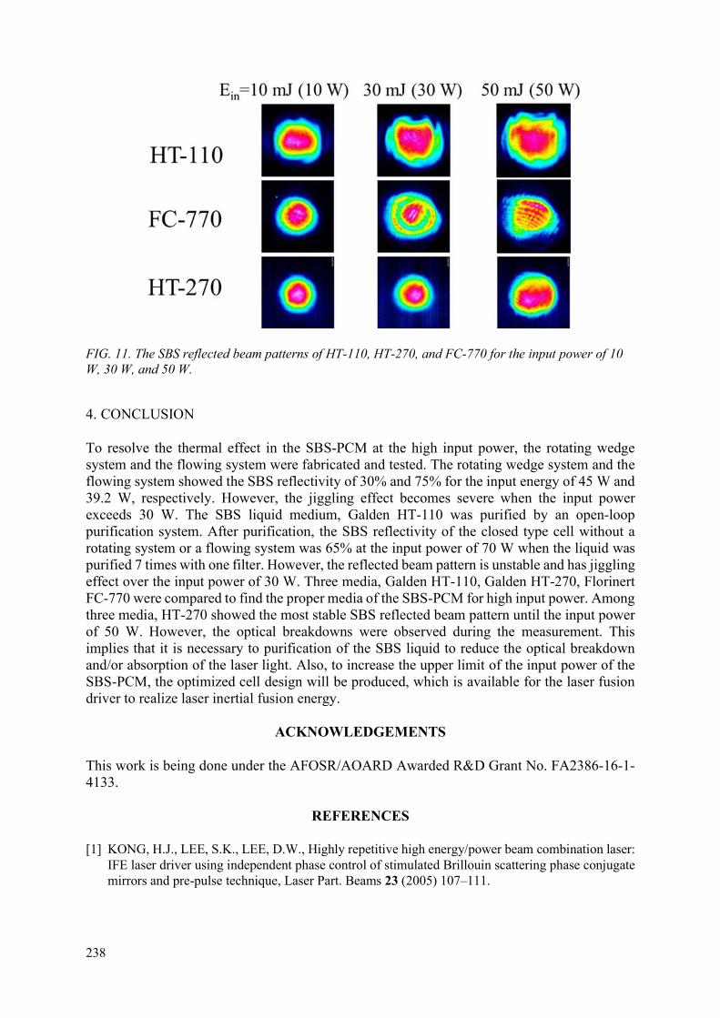
238
FIG. 11. The SBS reflected beam patterns of HT-110, HT-270, and FC-770 for the input power of 10 W, 30 W, and 50 W.
4. CONCLUSION
To resolve the thermal effect in the SBS-PCM at the high input power, the rotating wedge system and the flowing system were fabricated and tested. The rotating wedge system and the flowing system showed the SBS reflectivity of 30% and 75% for the input energy of 45 W and 39.2 W, respectively. However, the jiggling effect becomes severe when the input power exceeds 30 W. The SBS liquid medium, Galden HT-110 was purified by an open-loop purification system. After purification, the SBS reflectivity of the closed type cell without a rotating system or a flowing system was 65% at the input power of 70 W when the liquid was purified 7 times with one filter. However, the reflected beam pattern is unstable and has jiggling effect over the input power of 30 W. Three media, Galden HT-110, Galden HT-270, Florinert FC-770 were compared to find the proper media of the SBS-PCM for high input power. Among three media, HT-270 showed the most stable SBS reflected beam pattern until the input power of 50 W. However, the optical breakdowns were observed during the measurement. This implies that it is necessary to purification of the SBS liquid to reduce the optical breakdown and/or absorption of the laser light. Also, to increase the upper limit of the input power of the SBS-PCM, the optimized cell design will be produced, which is available for the laser fusion driver to realize laser inertial fusion energy.
ACKNOWLEDGEMENTS
This work is being done under the AFOSR/AOARD Awarded R&D Grant No. FA2386-16-1-4133.
REFERENCES
[1] KONG, H.J., LEE, S.K., LEE, D.W., Highly repetitive high energy/power beam combination laser: IFE laser driver using independent phase control of stimulated Brillouin scattering phase conjugate mirrors and pre-pulse technique, Laser Part. Beams 23 (2005) 107–111.

239
[2] KONG, H.J., YOON, J.W., SHIN, J.S., BEAK, D.H., LEE, B.J., Long term stabilization of the beam combination laser with a phase controlled stimulated Brillouin scattering phase conjugation mirrors for the laser fusion driver, Laser Part. Beams 24 (2006) 519–526.
[3] KONG, H.J., YOON, J.W., LEE, D.W., LEE, S.K., NAKATSUKA, M., Beam Combination Using Stimulated Brillouin Scattering Phase Conjugate Mirror for Laser Fusion Driver, J. Korean Phys. Soc. 49 (2006) 39–42.
[4] KONG, H.J., SHIN, J.S., YOON, J.W., BEAK, D.H., Wave-front dividing beam combined laser fusion driver using stimulated Brillouin scattering phase conjugation mirrors, Nucl. Fusion 49 (2009) 125002.
[5] KONG, H.J., PARK, S., CHA, S., KIM, J.S., 0.4 J/10 ns/10 kHz-4 kW coherent beam combined laser using stimulated Brillouin scattering phase conjugation mirrors for industrial applications, Phys. Status Solidi 10 (2013) 962–966.
[6] WAGNER, C., HARNED, N., EUV lithography: Lithography gets extreme, Nat. Photonics 4 (2010) 24–26.
[7] KOECHNER, W., Thermal Lensing in a Nd:YAG Laser Rod., Appl. Opt. 9 (1970) 2548–53. [8] KOECHNER, W., RICE, D.K., Effect of Birefringence on the Performance of Linearly Polarized
YAG:Nd Lasers, IEEE J. Quantum Electron. 6 (1970) 557–566. [9] GLAZE, J.A., GUCH, S., TRENHOLME, J.B., Parasitic Suppression in Large Aperture Nd:Glass
Disk Laser Amplifiers, Appl. Opt. 13 (1974) 2808. [10] FAN, T.Y., Laser beam combining for high-power, high-radiance sources, IEEE J. Sel. Top.
Quantum Electron 11 3(2005) 567–577 [11] GONSALVES, R.A., Phase retrieval and diversity in adaptive optics, Opt. Eng. 21 (1982) 829. [12] YARIV, A., PEPPER, D.M., Amplified reflection, phase conjugation, and oscillation in
degenerate four-wave mixing, Opt. Lett. 1 (1977) 16. [13] BARANOVA, N.B., ZEL’DOVICH, B.Y., Wavefront reversal of focused beams (theory of
stimulated Brillouin backscattering), Sov. J. Quantum Electron. 10 (1980) 555. [14] BOYD, R.W., RZAEWSKI, K., NARUM, P., Noise initiation of stimulated Brillouin scattering,
Phys. Rev. A, 42 (1990) 5514–5521. [15] KONG, H.J., LEE, S.K., LEE, D.W., GUO, H., Phase control of a stimulated Brillouin scattering
phase conjugate mirror by a self-generated density modulation, Appl. Phys. Lett. 86 (2005) 1–3. [16] SHIN, J.S. PARK, S.H., KONG, H.J., YOON, J.W., Phase stabilization of a wave-front dividing
four-beam combined amplifier with stimulated Brillouin scattering phase conjugate mirrors, Appl. Phys. Lett. 96 (2010) 3–5.
[17] EICHLER, H.J., MENZEL, R., SANDER, R., SMANDEK, B., Reflectivity enhancement of stimulated Brillouin scattering liquids by purification, Opt. Commun. 89 (1992) 260–262.
[18] YOSHIDA, H., KMETIK, V., FUJITA, H., NAKATSUKA, M., YAMANAKA, T., YOSHIDA, K., Heavy fluorocarbon liquids for a phase-conjugated stimulated Brillouin scattering mirror., Appl. Opt. 36 (1997) 3739–3744.
[19] HASI, W.L.J., LU, Z.W., GONG, S., LIU, S.J., LI, Q., HE, W.M., Investigation of stimulated Brillouin scattering media perfluoro-compound and perfluoropolyether with a low absorption coefficient and high power-load ability, Appl. Opt. 47 (2008) 1010-1014.
[20] KONG, H.J., PARK, S., CHA, S., AHN, H., LEE, H., OH, J., LEE, B. J., CHOI, S., KIM, J.S., Current status of the development of the Kumgang laser, Opt. Mater. Express 4 (2014) 2551–2558.

240
DELIVERY OF THE LASER BEAM AND TRANSMISSIVE OPTICS DEGRADATION IN KRF-BASED SHOCK-IGNITION INERTIAL FUSION ENERGY APPROACH
V.D. ZVORYKIN*,**, S.V. ARLANTSEV*, A.V. SHUTOV*, I.V. SMETANIN*, N.N. USTINOVSKII*, V.I. SHVEDUNOV*,***, D.S. YUROV***
*P.N. Lebedev Physical Institute of Russian Academy of Sciences, **National Research Nuclear University “MEPhI”,
***D.V. Skobel’tsyn Institute of Nuclear Physics, Moscow State University, Moscow, Russian Federation Email: [email protected]
Abstract
Two issues were concerned in the present research: (i) KrF laser pulse steering for the Shock Ignition Inertial Fusion Energy approach, which includes a direct amplification of both short (ps length) and long (ns length) pulses in large-aperture e-beam-pumped KrF amplifiers, laser beam delivering to a target with small attenuation and deterioration along ~100 m air pass; (ii) long-term degradation of KrF amplifier optical windows under intensive UV laser light, bremsstrahlung X ray and electron irradiation, which arises during deceleration and scattering of pumping e-beams.
1. INTRODUCTION
The current research aims at investigation towards an implementation of a direct-drive Shock Ignition (SI) concept of the Inertial Confinement Fusion (ICF) with e-beam-pumped Krypton Fluoride (KrF) laser [1]. Inherent properties of KrF laser, such as a short radiation wavelength λ = 248 nm, a broad bandwidth Δλ ~1.2 nm, a focal spot zooming along target imploding have been realized in very spatially and temporally uniform target-irradiation at the single-shot 3-kJ Nike facility (NRL, USA), while a reliable and efficient 5 Hz repetition-rate operation with up to 700 J output energy was demonstrated ibid. at Electra laser with a working gas recirculation cooling [2]. Such properties are just one need in a future laser-driven power plant using Inertial Fusion Energy (IFE) [3,4]. To be economically attractive, it needs to operate with pulse energy ~1 MJ at 5–10 Hz and overall (“plug”) efficiency ~7% for a duty cycle of about 1 year [5, 6]. In the SI ICF approach the main driving pulse of ~ 1014 W/cm2 intensity and of several tens nanosecond length (long pulse) is followed by a powerful final spike of hundred picoseconds duration (short pulse) with a peak intensity ~ 1016 W/cm2, which uploads a convergent shock wave and ignites the collapsed thermonuclear fuel. An appropriate laser pulse form is rather difficult to maintain in a quasi-steady amplification of the pulse stack in an angular multiplexing schema due to a heavy saturation of KrF amplifiers by a high-power spike [7]. An alternative way is to combine short & long pulses immediately on a target while they could be simultaneously amplified in the same amplifier chains due to a short gain recovery time τc 2 ns of KrF laser [8]. On this way we have demonstrated simultaneous amplification of a picosecond pulse train against 100-ns lasing pulse at a multistage hybrid Ti:Sapphire / KrF GARPUN-MTW laser facility [9]. Taking into account that a short pulse amplification law is the same for any pulse lengths τp ≤τc 2 ns, this confirms a principal ability of KrF laser pulse steering for the SI ICF via simultaneous amplification of short & long pulses. Such approach could tremendously simplify architecture of the IFE test facility [10].
Nonlinear effects that appear for high radiation power in a course of direct short-pulse amplification might strongly affect laser beam quality and amplification efficiency. Earlier experiments on direct amplification of picoseconds pulses in large-scale e-beam-pumped KrF

241
laser facilities Super-Sprite [11,12] and Super-ASHURA [13] with 60 cm aperture of a final amplifier did not shed light on this issue although achieved peak power of about 10 TW was much higher than a critical power for a UV radiation self-focusing (Pcr ~ 0.1 GW in atmospheric air and 3 orders of magnitude lower in laser windows). In present investigations since the first experiments at GARPUN-MTW laser [14] a small-scale self-focusing of radiation and multiple filamentation of the laser beam was observed (see also [15−17]), which broke up the beam into hundreds of filament-like thin (~ 300 μm in diameter) channels with a local intensity and fluence 200 times as high as an average value over the beam cross section. These filaments produced nonlinear energy losses in both gain medium and amplifier optical windows resulted in a low-level saturation of short-pulse energy, as well as damaged laser optics. To negotiate a laser beam filamentation, a chirped pulse amplification (CPA) scheme instead of a direct amplification was developed [18], which allowed obtaining ultra-short pulses (USP) of a femtosecond length with an extremely high peak-power using solid-state amplifiers [19]. The CPA for KrF lasers although having been demonstrated [20,21], but it is unlikely could be implemented in a MJ-class facility with angular-multiplexed large-aperture multiple beams because of a very difficult manufacturing and very costly large-scale diffracting gratings for a USP compression. Alternatively, “we explore a large negative two-photon resonantly-enhanced nonlinear refraction index in Xe [22], which could compensate a nonlinear phase shift acquired along propagation tract in air and in amplifier windows” [16].
Another problem to be solved for a reliable and efficient long-time rep-rate e-beam-pumped KrF laser operation is colouration of amplifier windows under irradiation by fast electrons and bremsstrahlung X rays [23–25]. Such irradiation arises due to pumping electron scattering and deceleration in a working gas and foil windows which serves for e-beam transportation from vacuum diodes into a laser chamber. Energy fluence of radiation escaped onto laser windows depends on pumping e-beam parameters and constructive features of a laser chamber. Up to now two pumping geometries were commonly realized in large-scale amplifiers, e.g. two-side beams or multi-side (from 4 to 8) beams. They are injected transversely to a laser chamber axis that is an optical axis of amplifier. These geometries provide effective and uniform energy deposition in a gas, if electron range is approximately equal to a transverse size of the chamber. Typically, it is about 300‒600 keV for chambers of 20‒100 cm lateral dimensions and working gas pressure 1‒2 atm. The bigger size, the lower pressure is used to reduce a mechanical load on laser windows. The chamber length (up to 200 cm) and width to length aspect ratio are optimized with taking into account non-saturable absorption and gain depletion in KrF medium by amplified spontaneous emission (ASE) which is rather high due to a large cross section of stimulated radiation and a short radiation and collisional lifetimes of an upper laser level [8]. The pumping pulse lengths are typically 100‒500 ns, being restricted by an optical strength of laser optics and a realistic amount of angularly multiplexed laser pulses (beams) which extracts stored energy in the gain medium in a quasi-steady manner [2].
To prevent e-beam pinching in self-produced magnetic field, an external magnetic field is applied along e-beam injection in a double-side pumping layout. It increases energy deposition in a gas and significantly reduces electron escape onto amplifier windows [23]. Bremsstrahlung X rays are produced during e-beam deceleration in a gas, foils and foil-support structures. In contrast to electrons, X ray irradiation of amplifier windows is not directly affected by applied magnetic field (only through redistribution of injected electrons). They both were measured at GARPUN laser module [23–25]. Based on these measurements e-beam fluence εe ≤ 1 mJ/cm2 (corresponding energy flux 10 kW/cm2 for 100-ns pumping pulse length) and bremsstrahlung X ray fluence εX ~ 10 mJ/cm2 (energy flux ~ 100 kW/cm2) per shot could be estimated in the IFE-scale laser amplifier [24]. Oppositely to electrons absorbed in a thin ~ 1 mm layer nearby an irradiated window surface, X rays penetrate through the windows, which thickness is a few

242
centimetres. Fast electrons and X rays, as well as intensive UV laser light break interatomic bonds in the material and generate a cascade of secondary electrons and holes. Being trapped by lattice imperfections or impurity inclusions they form various types of colour centres absorbing light mostly in UV/VUV and visible spectral domains [26, 27]. Therefore, distributions of colour centres in optical windows produced by both types of ionizing radiation are quite different. E-beam-induced absorption is appropriately described by an induced optical density OD – integral characteristic independent on window thickness, while X ray-induced absorption is described by X ray-induced absorption coefficient αX which corresponds to a nearly exponential distribution along window thickness. They both depend on absorbed doses (dose rates) of ionizing radiation. Under pulsed irradiation a short-lived transient induced absorption due to defect relaxation evolves to a long-lived residual one, which is accumulated pulse by pulse during irradiation run [23,25]. A total absorbed dose of ionizing radiation amassed in KrF laser driver windows for 1-year IFE duty cycle could be estimated around 30 MGy [25]. In addition to nonlinear losses and degradation of KrF laser driver windows darkening of the final optics and windows of a reactor chamber happens subjected to neutron, ion and gamma radiation from thermonuclear target explosions [28, 29]. All of them play a crucial role in laser beam delivery to a target. A long-term degradation of KrF laser windows under 1-MeV electrons is concerned in the present research and compared with our previous investigations at a pulsed e-beam source ELA [23,25,30‒33]. In 280-keV, 200 A/cm2, 80-ns e-beam pulses it delivered to tested samples energy fluence εe ~ 2 J/cm2 per shot, which is 3 orders of magnitude higher than measured at GARPUN laser. Effect of colour centres bleaching by CW UV light was also investigated, being a promising way to reduce induced absorption in KrF laser driver windows during IFE duty cycle.
2. NONLINEAR EFFECTS UNDER A DIRECT AMPLIFICATION OF SUB-TW PICOSECOND PULSES IN KRF AMPLIFIERS AND A LONG-DISTANCE TRANSPORTATION IN ATMOSPHERIC AIR
2.1. Ti:Sapphire / KrF GARPUN-MTW laser facility
Experiments on direct amplification of ps and ns pulses as well as laser pulse steering and beam delivery were performed at the hybrid Ti:Sapphire / KrF GARPUN-MTW laser (for details see ref. [8]). The general view of the facility hall is shown in Fig. 1(a). It consists of two front-end oscillators, a mirror ring pulse multiplexer and a chain of two large-aperture e-beam-pumped KrF amplifiers. The nanosecond discharge-pumped EMG 150 TMSC KrF laser oscillator of the Lambda Physik generates tunable narrow-band or wide-band 25 ns, 200 mJ UV pulses around 248 nm wavelength. The femtosecond Ti: Sapphire front-end Start-248 М of the Avesta Project Ltd. generates ~100 fs IR pulses, which energy after frequency conversion to the KrF gain band amounts to 0.5 mJ. A single UV USP was cut by a shutter from an original front-end 10 Hz sequence. “To obtain a train, a single USP was introduced into a multiplexer, formed by three flat highly reflecting mirrors and a beam splitter (a thin CaF2 plate with a dielectric coating). For a beam splitter with 30% reflection, the total train energy reached 0.1 mJ, and the energies of individual USPs in the train obeyed a ratio 3:5:1.5:0.5” [15]. The USP repetition period in the train was longer than the gain recovery time in KrF laser medium (~2 ns), and it was varied from 3 to 5 ns by changing the distance between the multiplexer mirrors. With the delay line shuttered, there was only the first USP of the train at the multiplexer output, which contained 33% of the total train energy. An initial beam diameter was 3 times telescoped by a vacuum spatial filter and forwarded into amplification tract with a total atmospheric air pass to a target chamber about 100 m. Plane and curved mirrors match the beam diameter with e-beam-pumped KrF preamplifier Berdysh and the final large-aperture GARPUN amplifier (Figs 1(b)–(c)). The final amplifier has a gain volume of 12 × 18 × 100 cm transversely pumped by two counter

243
propagating e-beams with a pulse duration ~100 ns, an electron energy of 350 keV and a current density of 50 A/cm2. In a free-running operation with a specific pumping power Wb = 0.7÷0.8 MW/cm3 of working gas mixture Ar/Kr/F2 at a pressure of 1.4 atm it produces laser energy up to 100 J. The Berdysh preamplifier with a volume of 8 × 8 × 110 cm transversely pumped by a one-side e-beam with similar parameters Wb = 0.6÷0.7 MW/cm3 and a working gas pressure of 1.8 atm generates about 25 J. Vacuum spatial filter incorporated between the amplifier cascades suppresses amplified spontaneous emission (ASE).
(a)
(b)
(c)
FIG. 1. (a) General view of GARPUN-MTW laser facility; (b) preamplifier Berdysh; (c) final amplifier GARPUN.
All these units were performed in different amplification schemes to produce single USP of sub-ps duration [14] and USP trains [15], or a combination of the USP train and a long (~ 100 ns) pulse equal in duration to a pumping time of KrF amplifiers [9]. To amplify single USPs and the USP trains three various optical layouts were investigated including: (i) a consequent double-pass amplification of USPs in both large-aperture preamplifier and amplifier modules; (ii) a four-pass amplification of USPs in the preamplifier and single-pass amplification in the final amplifier, and (iii) a four-pass amplification of USPs in the preamplifier followed by a double-pass amplification in the final amplifier. Comparative studies have been done to choose an optimal laser configuration that produced maximal USP energy, the shortest pulse duration with the lowest ASE input. It was a double-pass amplification in both KrF amplifiers (Fig. 2). The USP train energy in this layout attained 1.0 J. Single USP energy was on average lower by a factor of 2.5 than the total train energy. The maximal energy attained for a single USP amplification amounted 0.65 J. Pulse duration was measured by a single-shot autocorrelators based on two-photon fluorescence of BaF2 crystal or XeF mixture in a counter propagating

244
beams layout. Due to a group velocity dispersion along the amplification tract the output USP was stretched up to ≤ 1 ps. Thus, a USP peak power ~ 1 TW was attained.
FIG. 2. Layout of a double-pass amplification of a USP in GARPUN facility and laser-beam filamentation measurements.
To obtain combined pulses, USP train (or a single USP) firstly were amplified in a double-pass Berdysh preamplifier and finally in GARPUN regenerative amplifier. The latter was equipped by unstable confocal resonator formed by a totally reflecting spherical mirror with a radius of curvature 6 m and a semitransparent mirror deposited on the convex face of a meniscus lens with a radius of 1 m. Therefore, the resonator magnification was 6 and its length 2.5 m. “The concave surface of the meniscus lens had an antireflection coating, and its radius of curvature was selected in such a way as to make coincident the points of the imaginary foci of the meniscus lens and the mirror deposited on the convex surface. The wavefronts of the beam injected into the resonator and the radiation reflected from the mirror surface of the meniscus lens in the multiple passes through the resonator were thereby matched to each other” [34]. The output radiation was a superposition of the amplified USP train and 100-ns free-running oscillation pulse. System optimization included variations of injected USP periodicity and transparency of the input meniscus resonator mirror. For combined pulses the highest total energy, up to 30 J and maximal USP peak power ~ 0.2–0.3 TW in the train were achieved. Highly amplitude-modulated combined UV laser pulses support prolonged air ionization if compared with a convenient few ns ionization in a trace of a single USP. Such possibility is highly attractive for triggering and guiding of high-voltage electric discharges in atmosphere [34] and directed transfer of microwave radiation along artificial plasma waveguides [35]. These experiments revealed that USP energy in a course of amplification saturates at rather low level, a few times less than predicted from numerical simulations [8].
2.2. The laser beam filamentation
Effect of powerful radiation self-focusing originates from an intensity-dependent Kerr nonlinear additive to the refraction index n2 caused by polarization of medium in intensive laser field. A nonlinear phase shift along laser pulse propagation length for n2 > 0 induces a self-focusing of the whole beam with a central maximum in transverse intensity distribution. The self-focusing onset is defined by critical power 2
0 23 77 8crP , / n n (n0 is the linear refraction index), which corresponds to the equality of self-focusing and diffraction. As both effects depend on the beam diameter in the same manner, any defocusing mechanism is required to

245
arrest the beam collapse, e.g. a negative additive to the refraction index of electrons produced by laser field ionization of the matter. The dynamic balance of Kerr self-focusing and plasma defocusing 2 2f ef cn I I / , where ρef is an electron density, 2 2
0 0 /c em e is the critical
plasma density, 0 is the permittivity of vacuum, ω0 is the laser frequency; me and e are the electron mass and charge. Self-guided pulse propagation arises in the form of a narrow filament-like channel, which length multiply exceeds the Rayleigh length for linear beam focusing [36]. For very high “supercritical” laser power P >> Pcr “hot spots” in initial intensity distribution provoke a local self-focusing, and the beam spatially breaks up into multiple filaments governed by modulation instability [37]. Such situation is realized at the GARPUN-MTW facility during USP amplification resulted in multiple beam filamentation [14−17]. In the case of a four-pass amplification of USPs in the preamplifier, filaments were fully formed before passing the final amplifier [16]. In the optimal USP double-pass scheme in both amplifiers, filaments arose just 15 m beyond the final amplifier and they were observed up to ~ 100-m distance in the nearly collimated laser beam formed by a convex (M3) and concave (M4) mirrors (Fig. 3, upper panels).
2.2.1. Stochastic filamentation of a supercritical UV laser beam
Parameters of multiple light and plasma filaments were measured and their evolution along 100-m air pass was investigated. To visualize a UV laser beam, nonlinear fluorescence of K8 glass in the blue-green region of the spectrum was used, which was displayed by an objective on the optical profilometer Spiricon SP620U Beam Profiler (Ophir Photonics) (see Fig. 2). Glass fluorescence f was calibrated in dependence on the USP energy fluence ε at Ti: Sapphire front end. In a wide range of ε values differing by more than four orders of magnitude, the obtained dependence is described by the power function 0.4f [38]. It made possible to register simultaneously and without saturation of the profilometer CCD matrix both filaments and a background radiation with a large intensity difference (Fig. 3). A moiré-like beam pattern observed at the final amplifier output reproduced CaF2 windows structure (they are indeed not a single mono crystals but a merge of crystallite blocks), as block boundaries introduced phase modulation into transmitted radiation. Such a slight perturbation of the output radiation nearby the amplifier (with intensity variation no more than a few ten percent) nevertheless provoked at distances ≥ 15 m away from the final amplifier a distinct multiple filamentation pattern containing entirely formed filaments. About 300 randomly distributed filaments were counted over a collimated beam cross section of about 100 mm in size, which contains a fraction of 0.3 of the total USP energy ≈ 0.2 J, the rest being in a background radiation (so called energy reservoir). An average energy in each filament was ~ 0.2 mJ. Typical diameter of filaments measured at L ~ 30 m beyond the final amplfier was in the range df = 240÷340 μm (FWHM), peak intensity was If = (2.0±0.6)·1011 W/cm2 in average, and maximal fluence εf = 0.2±0.06 J/cm2. Power transferred in filaments Pf ~ 0.2 GW was a doubled Pcr. Electron density in filaments ρef ~ 3.5·1013 cm-3 was estimated from laser beam attenuation along 100-m distance [35]. It qualitatively agrees with a direct measurement of multiphoton ionization (MPI) of atmospheric air 𝜌 (𝑟) = ∑ 𝜎 𝜌 ∫ 𝐼 (𝑟, 𝑡) 𝑑𝑡, where 𝐾 = 𝑈 /ℏ𝜔 + 1 is the number of
photons required for ionization of air component with a density ρj and ionization potential Uj [39, 40]. For found parameters n2If≫ρef
(If)/2ρc+(1.22λ)2/8πn0df2, that is Kerr self-focusing is
much higher than plasma and diffraction de-focusing. “Therefore, instead of a conventional plasma-driven filamentation model, which is adequate to a pre-focused or squeezed laser beam [36], a plasma-free model needs to be sought for a large cross section slightly-focused or collimated UV beam of our concern. Indeed, our experiments revealed two important features: (i) the dominant role of resonance-enhanced multiphoton ionization (REMPI) processes in the

246
interaction of a deep UV laser radiation with atmospheric air instead of a direct MPI by IR light [39]; and (ii) rotational orientation of anisotropic oxygen and nitrogen molecules, i.e. stimulated rotational Raman scattering (SRRS) in the laser field of ps length USP [17]. Both processes change the polarization of the matter. They could contribute to the nonlinear refraction additionally to an instantaneous bound electrons response in molecules” [44]. Coherent SRRS arises when the pulse width (~ 1 ps) is shorter than the characteristic relaxation time of polarization (≥ 100 ps) [40] and the pulse spectrum is wider than the eigen frequency of the equivalent two-level model oscillator (i.e., the Stokes shift). When UV USP propagates in air, the SRRS in nitrogen between J=6 and J=8 rotational states was the dominating process, which is characterized by the Stokes shift of 75 cm-1 while the USP spectral width is ~ 200 cm-1. The laser light self-focusing under coherent SRRS was obtained theoretically by solving the USP envelope equation [17]. The found threshold of self-focusing was in a reasonable coincidence with the commonly accepted value Pcr = 0.1 GW. A perfect fit with the measured values of the energy per filament 0.2 mJ and of the filament diameter 300 µm was also obtained.
L=30 m L=50 m L=100 m
FIG. 3. K8 glass fluorescence at various distances L from the final amplifier (upper row), with circular periodic masks inserted 5-m beyond the amplifier (middle row) and with the X-cell at 5-m beyond the amplifier (bottom row); panel size is 4×5 cm. A circle in the bottom-left panel is an image of a red radiation accompanying UV USP interaction with Xe.

247
Comparison of filament patterns formed by a single USP and by the USP train showed “that they are very similar, that is position of individual filaments and their areal distribution did not change significantly in the nanosecond time scale. In addition, the patterns demonstrated a long-term stability when subsequent USPs were repeated in several minutes” [16]. Filament degradation is observed at the longest distances (Fig. 3), and “it could be explained by an impact of stochastic laser beam perturbations in air. For example, strong turbulence induced by local air heating with the fan in 1-m length region of the total 30 m beam pass from the final amplifier strongly affected on the radiation distribution and destroyed regular filament ordering by the periodic mask” [44].
2.2.2. Arranging of filaments into a perfect 2D array
As seen in Fig. 3 (upper row), “filaments are randomly developed around stochastic and deterministic perturbations of intensity or phase caused by imperfections of laser gain medium, optical windows, air turbulences, as well as by diffraction at optics apertures with a hard edge” [43]. While filaments do appear, it is of our interest arranging of typical stochastic multiple filament patterns into a well-ordered filament distribution. Such regular filament arrays in air have a potential to be used as virtual laser-supported plasma antennas and waveguides to transfer microwave radiation [35]. “The main idea to control a filamentation process is to introduce initial regular perturbations in the beam that need to overcome the natural ones. Linear diffraction as shown in numerical simulations [42] is capable to provide a dominant initial partitioning of power in a nonlinear propagation of a supercritical beam and thus to arrange a multiple filament distribution” [43]. We have used two masks with circular or square periodic apertures of 5 mm size inserted 5 m beyond the final amplifier, each transmitting individual power ~ (5−10)Pcr, which was enough to initiate afterwards in each cut-off beamlet a few filaments [43, 44]. A total number of hexagonally packed apertures in the masks over beam cross section amounted to hundreds. In order to obtain a perfect diffraction-controlled filament array for a given aperture radii a =2.5 mm we varied a distance Ld from the mask. It was achieved for Ld ≈ 25 m and corresponded to Fresnel number 2 2/ /F dN a L a R =1, where R = −170 m is the radius of curvature of a slightly convergent incident beam. Only one central maximum in a diffraction pattern exists in this case, and it favours the single “super filament” gained in a competition. These super filaments assigned by diffraction maxima formed a continuous plasma string array of about 20-m length.
2.3. Multiphoton air ionization and a long-distance attenuation of KrF laser radiation
Multiple filamentation of a supercritical UV beam in ambient air via MPI produces plasma channels that are of a great interest for several promising applications mentioned above. Besides, defocusing of laser radiation in plasma is usually considered as the main mechanism that prevents collapsing of a supercritical beam, i.e. balances Kerr self-focusing. As critical power of self-focusing for a short-wavelength KrF laser radiation is rather low (thirty times less than in IR spectral domain), it becomes filamented very easy and laser beam contains more filaments (typically each filament transfers a power about Pcr). On the other hand, probability of direct MPI in the UV domain is significantly higher, as fewer amounts of photons are required. Although photon energy (5 eV for the 248 nm KrF laser) is low compared to the ionization potentials of the main air components, 2-photon resonances do exist that makes possible an effective Resonance Enhanced Multiphoton Ionization (REMPI). We have mention before that such resonance could manage a coherent filamentation process instead of plasma defocusing. Prior to this study, 248 nm laser was believed to ionize atmospheric air mostly through direct 3 photon MPI of molecular O2, though published data on relevant ionization

248
mechanisms and rates are somewhat contradictory. Direct 4-photon MPI and (3+1) (REMPI) were reported both in N2 and Ar with large scatter in the magnitude of ionization rates. Ionization contribution of water vapor was not studied yet and its ionization rate is not known, although for typical laboratory air conditions (T = 21ºC and relative humidity η = 40%) the H2O content becomes equal to Ar content (~1%). We elucidated these issues in the present research [39, 40]. Experiments were performed within a broad 108÷1013 W/cm2 intensity and 0.01÷1 atm pressure range using 160-fs USP of the frequency-tripled Ti: Sapphire front-end and long 25-ns pulses of a discharge-pumped KrF laser. The former generated a broadband USP (Δλ~1 nm) with a central wavelength of λ= 248.5 nm. The latter generated a narrow band radiation (Δλ ~ 10-3 nm), tunable within a range of λ=248.0÷248.8 nm. To measure plasma density a photoconductivity technique was developed earlier [45]. We have experimentally shown that it is (2+1) REMPI of water vapor naturally contained in atmospheric air that acts as the dominant process of air ionization. “It occurs through 2-photon resonant excitation of water molecule which results in quadratic dependence of electron density on laser intensity at lower laser intensities of 108 ÷ 1010 W/cm2 in the long pulse, and in cubic dependence at higher intensities of 1010 ÷ 1013 W/cm2 in the short pulse. Direct 3-photon ionization and (3+1) REMPI took place respectively in pure O2 and N2 and their contributions to air ionization are in the ratio of 5: 3. Total ionization rate of O2 and N2 in atmospheric air is about an order of magnitude less than that of water vapor. Relevant ionization coefficients (effective MPI cross sections) have been measured, and that for the H2O molecule is more than 2–3 orders of magnitude larger than the others” [40].
Attenuation and deterioration of powerful UV radiation under propagation along 100-m pass in atmospheric air was investigated. Measured by calorimeters attenuation of 0.2 J,1 ps USP with 0.2 TW peak power and 80 mJ, 20 ns pulses with 4 MW peak power were approximated by exponential fits. Attenuation coefficient for the USP 6.9×10⁻³ m-1 appeared to be 3.3 times as much as for 20 ns pulses (2.1×10⁻³ m-1). We assumed this difference arose of high-intensity filaments, which ionize air effectively via (2+1) REMPI of H2O molecules, while attenuation of low-intensity (or background radiation) is caused by linear losses. Electron density in filaments was estimated on the base of these measurements in assumption that all nonlinear energy losses of the USP along the propagation pass (with the exception of linear ones) are spent for a 3 photon ionization. The obtained value correlates with direct measurements of atmospheric air ionization rate and filament parameters.
2.4. Nonlinear interaction of high-power KrF laser pulses with amplifier gain medium and optical windows
When filaments arise in the laser beam, they concentrate extra high peak intensity If ~ 2×10¹¹ W/cm2 and energy fluence εf ~ 0.2 J/cm2, which are 200-fold bigger than the averaged values over laser beam cross section. Energy fluence in filaments exceeds by two orders of magnitude the saturation energy fluence εsat = 2 mJ/cm2, which is a key parameter for USP amplification in KrF gain medium. Moreover, it exceeds significantly the maximum fluence εlim = 20–40 mJ/ cm2, which can be ever achieved in an undesired heavily saturated regime with low laser efficiency [15]. It means that the KrF gain medium would absorb filaments if they arise in front of amplifier entrance, as it was in the case of a four-pass USP amplification in the preamplifier. Although a background radiation, which is measured to contain ~ 70% of the whole USP energy, is still amplified, absorption of filaments restricts the attained USP energy.
Additional losses for high-intensity filaments are introduced by a nonlinear absorption, stimulated Raman scattering (SRS) and radiation spectra extra broadening in amplifier windows Nonlinear absorption of powerful UV laser pulses was measured in various optical materials

249
suitable for KrF laser optics and its effect on the attainable short-pulse energy density was evaluated. CaF2 was appeared to be the most transparent material in respect to nonlinear absorption of short pulses as it proceeds via 3 photon absorption [46−49]. It was chosen for amplifier windows but even this rather stable material is strongly affected by multiple filaments of a supercritical laser beam. For instance, filaments are evidently seen in fluorescence of CaF2 sample in Fig. 4(a) when undergoing a passage of multiply filamented supercritical laser beam. Damaged by filaments, output CaF2 window of Berdysh preamplifier when it operated in a four-pass layout is shown in Fig. 4(b).
(a) (b)
FIG. 4. (a) CaF2 fluorescence under filamented laser beam pass; (b )damaged by filaments preamplifier window.
Nonlinear interaction of UV radiation with CaF2 samples was investigated in the intensity range 109÷5×10¹¹ W/cm2. Experiments were performed at Ti: Sapphire front-end with the USP length of 100-fs (FWHM). Radiation was focused by the F=2 m lens in the 2-cm thick sample, which was approximately equal to amplifier window thickness. The sample was placed in the beam waist at a distance of ~8 cm from the focal plane (Fig. 5). The radiation incident on the sample was attenuated (step by step, using a diffraction attenuator) by a factor of 100 of the maximal value of 0.1 mJ (the corresponding power ~ 1 GW); the spot diameter ~ 300 mm (FWHM), approximately coincided with the average diameter of individual filaments in the USP beam. Therefore, conditions allowing for the transmission of individual filaments through the amplifier window were reproduced in a much wider range of peak powers, which obviously exceeded the critical filamentation power in CaF2. The radiation transmitted through the “sample was directed to a spectrometer ASP-150 (Avesta Project Ltd.) with a CCD array. The integrals over the spectral distributions of the radiation transmitted through the sample and the radiation propagating in the absence of sample were compared to find the relative value of radiation transmission (reduction), caused by a total effect of nonlinear absorption and scattering” [15]. This allowed us to exclude the effect of spectral broadening on measurements with photodiodes, which have a strong dependence of the sensitivity on radiation wavelength in the UV region.
For small scattering angles (see layout in Fig. 5(a) the radiation transmitted through air has broad spectral wings, built up from the central wavelength at ~10 nm (Fig. 6). Such a spectral shift by an order of magnitude corresponds to a vibrational quantum of the ground state of

250
molecular oxygen 𝜔e=1580 cm-1 (0.196 eV) [50]. Therefore, we can conclude that the broad spectral wings arose as a result of the SRS on the vibrational levels of O2 molecules. In the case of radiation transmitted through a CaF2 sample, a rather large fraction of energy (up to several tens of percent) were concentrated in wide wings. The half-width, ~ 20 nm, greatly exceeded the gain band of the KrF laser transition (~2.5 nm). In addition to broad spectral wings, there is a strong broadening of the сentral maximum, and several spectral peaks appear on it, which corresponds to the SRS of different order in CaF2 crystals [51,52]. In air (where some absorption of focused radiation could also be expected), the integral over the spectrum within the measurement error was linearly dependent on the incident energy (Fig. 7). Without an attenuator, the USP energy was directly measured by a calorimeter before and after beam focusing, and coincided with the measurement accuracy. In this sense, integrals over the spectrum were tied to the incident and transmitted USP energies (powers).
FIG. 5. (a) Measurement schemes of transmission of CaF2 sample; (b) spectral-angular radiation diagram. 1-lens, 2- CaF2 sample, 3-aperture, 4-spectrometer. Roman numerals indicate the course of the beam in the absence of (I) and in the presence of a sample (II).
FIG. 6. Spectra of radiation focused in (1) air and (2) CaF2 sample at paraxial angles.

251
It is seen that significant nonlinear losses in CaF2 occur for the USP peak power of more than 0.1 GW, which corresponds to the incident radiation intensity on the sample P ~ 1011 W/cm2. With increasing power nonlinear losses increase and at P=1 GW reach ~ 80%. The best fit to a
3 photon absorption attenuation law 1/220 01 2I l I I l
(where I0 is an insident intensity, γ is a
3 photon absorption coefficient, l is a sample thickness) with accounting for temporal and spatial intensity distribution was obtained for γ= (1.1±0.3)×10-22 см3/Вт2. This value is 3-fold bigger than measured in [47] for the USP length 450 fs apparently because of an input of radiation scattering in present experiments. For bigger scattering angles (see layout of Fig. 5(b)), Stokes and anti-Stokes components of SRS with Raman shifts 157, 218, 289, and 332 cm-1 were observed in the spectra, their number being increased with an angle. When found above γ value is applied for a nonlinear absorption and scattering in a 4-cm thick CaF2 window of the final amplifier, the loss of each filament is estimated ≈ 63%.
In addition, due to the broadening of the radiation spectrum in CaF2, the fraction of the transmitted radiation in the KrF gain band is no more than 30%. Thus, in the case of filaments formation in the amplification tract, only 90% of the radiation in filaments pass through the amplifier windows. With accounting for a background radiation and Fresnel reflection a window transmission needs to be about 64%. In the experiment, the measured transmission of the amplifier window for a multiply filamented laser beam was ≈ 60%.
FIG. 7. Transmittance of radiation (1) focuced in air and (2) in CaF2 vs. USP peak power (intensity); shaded region corresponds to filaments range.

252
2.5. Suppression of KrF laser beam filamentation in xenon
Therefore, a suppression of a beam filamentation is an important issue, first, for a reliable laser facility operation with a maximal USP energy, and, second, to prevent laser beam deterioration under propagation along ~ 100-m distance from the final amplifier exit to a target [38].We employed xenon gas, which has a large (70-fold higher than in air) negative two-photon resonantly enhanced nonlinear refraction index [22] to compensate a nonlinear phase incursion along the USP amplification tract in air and in amplifier windows. When filamented beam passed through a Xe cell of 2.5-m length, a pronounced effect of filament defocusing was observed even at rather low Xe pressure of 0.1 atm (Fig. 8). A fraction of the UV radiation lost in 1-atm Xe increased with the USP energy but did not exceed 20% [53]. Interaction of the UV USP with Xe was accompanied by a narrow-angle monochromatic coherent cone emission at 828-nm wavelength is explained by a stimulated hyper-Raman scattering and amplified
spontaneous emission at the transition 00 16 1/ 2 6 3/ 2p s of atomic Xe [54].
FIG. 8. (a) Filamented UV beam when passing through air; (b) Xe-cell; a far-field zone of coherent red radiation.
The other important quests were investigated: (i) whether it is possible to prevent multiple filamentation of a supercritical USP beam if to move the Xe cell closer to the final amplifier than the typical filamentation length (~ 15 m) and (ii) how long will be a filamentation-free pass in air beyond the cell. To learn these issues we set the Xe cell at 5-m distance from the amplifier and measured beam profiles at various distances away from the cell (see layout in Fig. 2). An effective beam homogenizing occurred with Xe and such effect was holding out at distances up to 50 m (bottom row in Fig. 3). A circle at a bottom-left panel corresponds to a near field of accompanying red radiation; a speckled inner structure indicates a coherent nature of the red radiation. It confirms that filaments are phase-matched during their propagation.
With an implemented Xe cell the best choice of a direct USP amplification scheme at GARPUN-MTW laser facility was successive double-pass USP amplification in both large-aperture KrF amplifiers. In target irradiation experiments, the following laser parameters were achieved in such scheme: (a) the USP energy at a target 0.25 J; (b) pulse duration less than 1 ps; (c) USP contrast with respect to the ASE energy density ~ 3·105 and ~ 3·1010 for the peak ASE intensity; (d) beam divergence 0.14 m rad at 0.1 level of the maximum intensity or 0.5 of the USP energy. When being focused with f/3 mirror (focal length of 0.3 m), the radiation intensity at a target achieved ~ 1016 W/cm2 in a focal spot of 70 μm. The latter was determined

253
by mirror aberrations. It is expected that with a perfect parabolic focusing mirror a spot size would be reduced while peak intensity will be increase by 1–2 orders of magnitude [38].
3. A LONG-TERM TRANSMISSION DEGRADATION OF UV OPTICAL MATERIALS UNDER IRRADIATION BY CW 1-MEV ELECTRON BEAM
3.1. Powerful CW linac electron source for optical samples irradiation
3.1.1. Description of an accelerator
A compact 25 kW CW linear electron accelerator (linac) with electron energy 1 MeV and e-beam current up to 25 mA has been developed for materials study [55]. An overview of the linac and its schematic diagram are shown in Fig. 9.
FIG. 9. An overview of 25-kW CW linac and its layout: 1 – an electron gun; 2 – a klystron; 3 – magnetic shielding; 4 – an accelerating structure; 5, 7 –ion pumps; 6 – a bending magnet; 8 – a divergence camera; 9 – RF system.
“An electron gun (1) with two focusing electrodes and an operating cathode voltage of -15 kV is located directly at the input flange of the accelerating structure (4). Focusing electrode voltage controls an output gun current from 0 to 250 mA. On axis coupled biperiodic accelerating structure operates at a frequency of 2450 MHz. A klystron with a maximum output power of 50 kW (2) supplies the accelerating structure with radio-frequency (RF) power through the central accelerating cavity. Similar high voltage allows to use a common power supply for the klystron and the electron gun. The klystron operates in a self-oscillating mode provided by a low power RF system (9) which fixes out a positive feedback loop between the klystron and accelerating structure. Magnetic shielding (3) is installed above the structure. Steering coils and solenoidal lens are located between the structure and magnetic shielding. The accelerator vacuum is provided by an ion pump (5) and a sputter-ion pump of the electron gun. Depending on beam applications different systems can be installed at the output of the accelerating structure. To measure high power beam parameters a Faraday cup with water cooling is placed at the output, provided with vacuum system comprising a rough pump and a turbomolecular pump. The beam scanning system, consisting of a beam divergence camera (8),

254
bending magnet (6) and an ion pump (7) is used for materials irradiation. The bending magnet is powered by the voltage with an amplitude and shape required for the formation of a uniform radiation field over the entire surface of the output window with 5x70 cm2 dimensions. Accelerator operating volume is separated from atmosphere by 50 microns titanium foil fixed at the beam divergence camera output flange. The accelerating structure and the klystron are cooled with distilled water. A total water consumption of accelerator cooling system is 120 l/min.
The accelerator operation is managed by the control system based on programmable microcontrollers (PMC). The system provides control of all accelerator systems via the remote terminal and information on their operation status. The control system is equipped with a set of emergency – red buttons, and operational interlocks – accelerator hall open door, poor ventilation level, bad vacuum, insufficient structure and klystron water flow, unlocked accelerator case, as well as klystron beam and body”5 overcurrent.
3.1.2. The linac optimization and adjustment for materials irradiation
The linac was substantively modified and adjusted for optical samples irradiation with absorbed doses as high as 20 MGy. For this goal a RF power input port with adjustable coupling coefficient has been developed. The optimum coupling coefficient 𝛽, providing no reflected wave in the waveguide, is related to the beam power 𝑃 and power losses in the walls of the
accelerating structure Pac as follows: β=1+Pb
Pac. Conventional power input port design provides
a constant coupling coefficient. Therefore, during operation with beam power different from value, on which coupling coefficient was tuned, reflected wave from the accelerating structure was formed leading to the klystron stability and reliability degradation. We used metal plungers with variable length mounted on the wide walls of the waveguide near the power input window. Several configurations with a different arrangement and number of the plungers were examined: 4 symmetrically arranged (2 on each wide wall of the waveguide) plungers at a distance of about 3 mm from the walls of the power input window aperture; 2 plungers facing each other in the middle of the waveguide wide wall; a plunger centred on the wide wall of the waveguide.
Numerical simulations were performed using CST Studio Suite software, as well as electromagnetic measurements of the assembled test S-band accelerating structure (resonance frequency is 2450 MHz) were carried out. The configuration with one plunger, centred on the wide wall of the waveguide at a distance of a quarter of a wavelength from power input window, performed the best results (Fig. 10). It provides a minimal impact on the resonant frequency of the power input unit and electromagnetic field distribution on the axis of the accelerating structure and enables to adjust the coupling coefficient over a wide range (Fig. 11).
5 accelconf.web.cern.ch

255
FIG. 10. A cutaway view of the model of the test acceleration structure with one plunger for simulation in CST Studio Suite.
An additional water-cooled pumping unit has been designed, manufactured and installed between the klystron and accelerating structure. Due to the low vacuum conductivity of the accelerating structure and the presence of vacuum pumps only in the ends of the structure, in the middle of the structure, near the power input unit, the vacuum level during operation can be 1-2 orders of magnitude lower than that near the pumps that may lead to vacuum breakdowns. Installation of additional pumping unit with ion pump can solve this problem. The pumping unit represents a vacuum chamber and a waveguide with holes on the narrow walls for pumping located inside the chamber. Cooling is provided by distilled water.
Figure 12 shows a picture of the pumping unit and ion pump with pumping speed of 25 l/s before installation on the accelerator.
(a)
(b)
FIG. 11. Dependence of (a) coupling coefficient and (b) resonance frequency of the test accelerating structure on the plunger length.

256
FIG. 12. A picture of the additional pumping unit and ion pump before installing.
3.1.3. UV optical materials for KrF laser windows and coatings
“Samples of various UV optical materials, i.e. different-grade fused silica glasses SiO2, alkaline earth fluoride crystals CaF2, MgF2 and leucosapphire Al2O3 crystals are commonly used as KrF laser windows or coatings of multilayer mirrors” [59]. An initial transmittance of these materials with account for Fresnel reflection was measured by a spectrophotometer Specord M40 in the UV and visible spectral domains, and it is shown in Fig. 13. “Fused silica is considered to be the material of choice for reactor chamber windows and final Fresnel lenses [29], as well as for KrF laser driver windows [2]. Large-size (~1-m), high-quality thermomechanical and radiation-stable optical elements can be manufactured of different kinds of this glass. Russian KU-1 glass and analogues Corning 7980 have hydroxyl OH concentration ~1000 ppm, other impurities (mainly chlorine) are from ~200 ppm (KU-1) to 20 ppm (ArF- grade Corning 7980). The novel KS-4V glass from I.V. Grebenshchikov Institute of Silicate Chemistry has impurity concentration (of the main 15 elements) less than 0.5 ppm, OH less than 0.1 ppm, and chlorine less than 20 ppm. Fluorite (CaF2) crystals although being less mechanically strength are well suitable for fluorine environment in UV and VUV domains as laser windows”6. Besides, this is the only material suitable for high-intensity UV USP radiation [47‒49]. The impurity concentration in CaF2 from S.I. Vavilov State Optical Institute was ~15 ppm. MgF2 crystals and leicosapphire Al2O3 being highly resistant to fluorine etching and possessing the lowest and the highest reflection indexes “are common materials for multilayer AR and HR coatings of KrF laser windows and mirrors. High-purity MgF2 samples from Corning, Kerth Cristalle were chosen for testing along with MgF2”6 and Al2O3 samples from State Optical Institute.
6 microbeam.eu
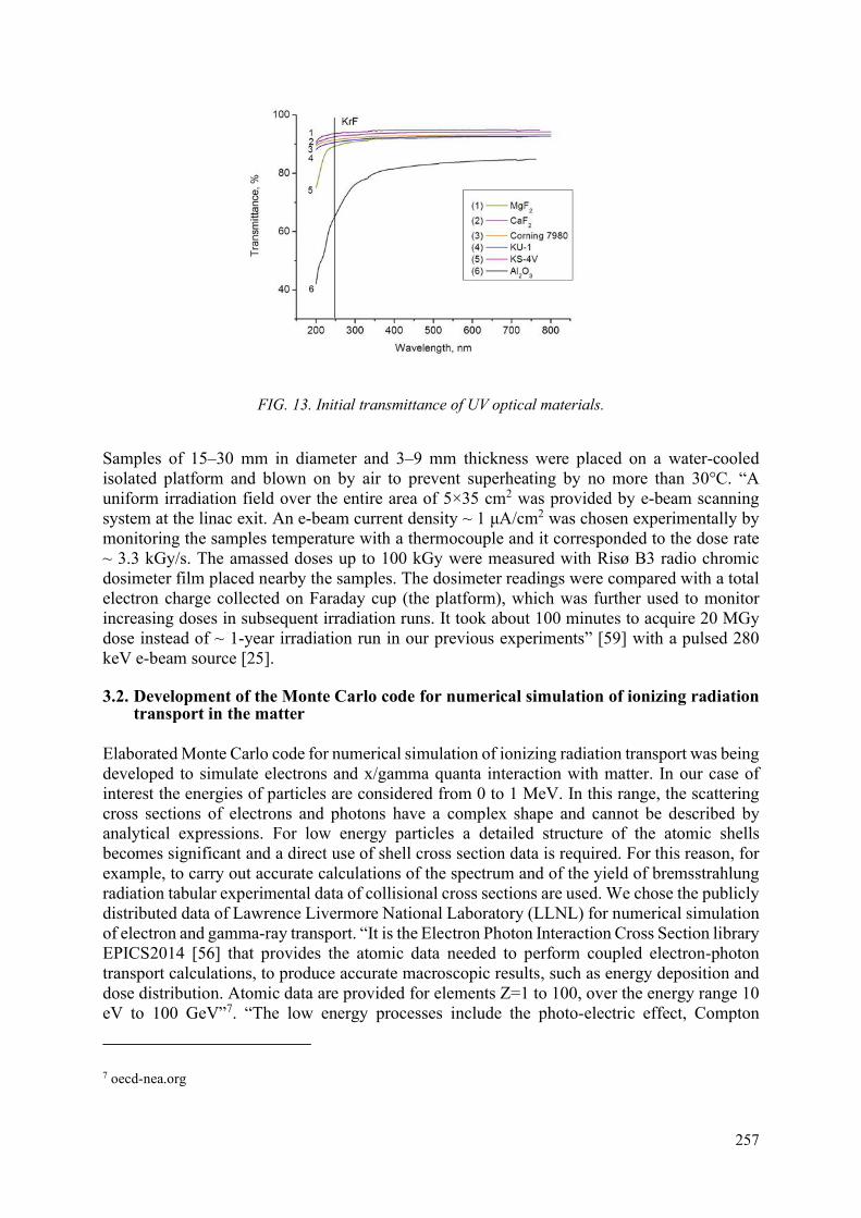
257
FIG. 13. Initial transmittance of UV optical materials.
Samples of 15–30 mm in diameter and 3–9 mm thickness were placed on a water-cooled isolated platform and blown on by air to prevent superheating by no more than 30°C. “A uniform irradiation field over the entire area of 5×35 cm2 was provided by e-beam scanning system at the linac exit. An e-beam current density ~ 1 μA/cm2 was chosen experimentally by monitoring the samples temperature with a thermocouple and it corresponded to the dose rate ~ 3.3 kGy/s. The amassed doses up to 100 kGy were measured with Risø B3 radio chromic dosimeter film placed nearby the samples. The dosimeter readings were compared with a total electron charge collected on Faraday cup (the platform), which was further used to monitor increasing doses in subsequent irradiation runs. It took about 100 minutes to acquire 20 MGy dose instead of ~ 1-year irradiation run in our previous experiments” [59] with a pulsed 280 keV e-beam source [25].
3.2. Development of the Monte Carlo code for numerical simulation of ionizing radiation transport in the matter
Elaborated Monte Carlo code for numerical simulation of ionizing radiation transport was being developed to simulate electrons and x/gamma quanta interaction with matter. In our case of interest the energies of particles are considered from 0 to 1 MeV. In this range, the scattering cross sections of electrons and photons have a complex shape and cannot be described by analytical expressions. For low energy particles a detailed structure of the atomic shells becomes significant and a direct use of shell cross section data is required. For this reason, for example, to carry out accurate calculations of the spectrum and of the yield of bremsstrahlung radiation tabular experimental data of collisional cross sections are used. We chose the publicly distributed data of Lawrence Livermore National Laboratory (LLNL) for numerical simulation of electron and gamma-ray transport. “It is the Electron Photon Interaction Cross Section library EPICS2014 [56] that provides the atomic data needed to perform coupled electron-photon transport calculations, to produce accurate macroscopic results, such as energy deposition and dose distribution. Atomic data are provided for elements Z=1 to 100, over the energy range 10 eV to 100 GeV”7. “The low energy processes include the photo-electric effect, Compton
7 oecd-nea.org

258
scattering, Rayleigh scattering, bremsstrahlung radiation and ionization, fluorescence and Auger electron emission of excited atoms”8. The data used for a sampling are extracted from tables of the evaluated data library EPICS2014 files: EPDL (Evaluated Photons Data Library); EEDL (Evaluated Electrons Data Library); EADL (Evaluated Atomic Data Library); EXDL (photon Excitation Data Library). “These files provide the following for the simulation of low energy processes: total cross-sections for photoelectric effect, Compton scattering, Rayleigh scattering and bremsstrahlung radiation; subshell integrated cross sections for photo-electric effect and ionization; energy spectra of the secondaries for electron processes; scattering functions for the Compton effect; form factors”9; transition probabilities between subshells for fluorescence and the Auger effect. The total cross sections for the Compton scattering process, for the Rayleigh scattering process and bremsstrahlung radiation are determined from the EPDL and EEDL data. The “angular and energy distribution of the incoherently scattered photons is given by the product of the Klein-Nishina formula and the tabulated scattering function”8. “The coherent scattered photon angle is sampled from the distribution obtained by the product of the Rayleigh formula and the square of form factor”9 from EADL. For use in simulations, the data from EADL, EEDL, EPDL, EXDL presented in the Livermore ENDL format need to be reduced to simple tabulated form for each element. For this purpose, a program ‘Epics2014read’ has been developed for reading and interpolation of the libraries data for their future use.
The developed Monte Carlo code was applied to simulate the electron beam and X / gamma-ray passage through samples of various UV optical materials SiO2, CaF2, MgF2, Al2O3. Experimental database EPICS2014 for cross sections of electrons and photons interaction with matter were used. For example, Fig. 14 demonstrates a screen window for 1-MeV e-beam transmitting SiO2 sample of 1-mm thickness, particle and energy distributions for transmitted, scattered and absorbed electrons. Fig. 15 demonstrates a screen window for 1-MeV gamma-rays transmitting CaF2 sample of 400-mm thickness.
FIG. 14. A screen window for 1-MeV electrons transmitting SiO2 sample of 1-mm thickness.
8 mafiadoc.com 9 geant4.web.cern.ch

259
FIG. 15. A screen window for 1-MeV gamma-rays transmitting CaF2 sample of 400-mm thickness.
The range of electrons in a sample and absorbed energy (dose) distribution with a depth are defined by energy losses in collisions with atoms and scattering relative to the initial direction of injection. It was found in simulations that the range of 1-MeV electrons in SiO2 is about 1.8 mm, while the maximum of the absorbed energy dεe/dx (εe is e-beam energy fluence) is achieved at ~ 0.45mm, and ~ 90% of beam energy is absorbed up to ~ 1.3 mm. The range in Al2O3 was ~ 1.1 mm, and 90% of energy was absorbed up to 0.75 mm. In CaF2, these parameters are correspondingly ~1.5 mm and 1.0 mm. In the whole, the maximum absorbed dose defined as D = (dεe/dx)max/ρ appears to be very close in all materials. For a given electron energy E = 1 MeV it can be expressed through e-beam energy fluence as D [kGy] ≈ 3.3×εe [J/cm2]. As sample thickness is always larger than the electron range, e-beam induced absorption is described by an optical density OD, which is defined as a natural logarithm of transmittance ratio of initial to irradiated sample. It characterizes an integral absorption in the given window material independently on its thickness. Oppositely, bremsstrahlung gamma rays penetrate through the windows, which thickness is typically a few centimetres. For this reason, induced absorption coefficient αsat is more adequate for x/gamma-rays instead of an optical density.
3.3. E-beam-induced colour centres in optical materials and their bleaching by UV radiation
The transmittance spectra of tested samples were measured in the spectral range from 200 to 750 nm with the spectrophotometer in a few hours after irradiation with 1-MeV electrons. The spectra did not change between subsequent irradiation runs of a few days. After the final irradiation all samples were kept in a dark box at a room temperature for about 6 months. During this time their transmittance increased by no more than a few percent. The effect of KrF laser radiation on colour centres bleaching was investigated earlier [25,33]. Bleaching of colour centres by continuous UV/visible radiation was investigated in the present research using a mercury lamp PRK-2 which produces line emission with the most intensive lines at UV and visible wavelengths 248.2; 253.7; 265.2…302.2/2.6; 312.6/3.2 and 365.0/6.2 nm. To increase samples illuminance, they were placed in a line onto Al mirror at 4 cm distance from the lamp axis. Two irradiation runs for 18 hours each were undertaken with transmittance spectra measurements between irradiations. The optical density OD of e-beam-induced absorption was then plotted. The OD spectra of different SiO2 glasses are shown in Figs 16‒18.

260
a b
FIG. 16. (a) OD spectra of KU-1 glass after successive e-beam irradiation runs with various εe; (b) OD after the last e-beam irradiation (1), after 6-months relaxation (2), after 18-hour (3) and 36-hour UV post irradiation (4).
a
b
FIG. 17. (a) OD spectra of Corning 7980 glass after successive e-beam irradiation runs with various εe; (b) OD after the last e-beam irradiation (1), after 6-months relaxation (2), after 18-hour (3) and 36-hour UV post irradiation (4).
a
b
FIG. 18. (a) OD spectra of KS-4V glass after successive e-beam irradiation runs with various εe; (b) OD after the last e-beam irradiation (1), after 6-months relaxation (2), after 18-hour (3) and 36-hour UV post irradiation (4).

261
The induced OD of “wet” glasses with a high OH content, 7.6-mm thick KU-1 and 3-mm thick Corning 7980 in the UV spectral range gradually increases in the course of irradiation. Absorption bands centred at ~ 215 and 260 nm wavelengths are attributed to E΄ centres and non-bridging oxygen hole centres (NBOHC) [25, 57, 58]. In contrast to [28, 29, 58] they have no an absorption band around 620 nm. A “dry” 8.6-mm thick KS-4V glass with a low OH content reveals the minimal absorption bands in the spectrum. All glasses demonstrated saturation of OD in dependence on energy fluence (absorbed dose). At 248-nm KrF laser wavelength the lowest saturated ODsat (248 nm) ≈ 0.12 was observed in KS-4V glass [59]. Besides, this glass demonstrates the best colour centres bleaching by UV post irradiation.
E-beam-induced OD in 4-mm thick CaF2 crystal is shown in Fig. 19. Prominent absorption bands in UV and visible spectral ranges at ~ 224, 340, 397, 580 nm are well known from experiments with e-beam [31,32,60,61], X ray [62], gamma-ray [63,64] and neutron irradiation [29, 65]. They belong to various colour centres and their aggregates. The saturated optical density ODsat (248 nm) ≈ 0.42 [59] appeared to be much higher than in our experiments with a 280-keV pulsed e-beam source [31, 32]. Interstitial atoms in the lattice produced by 1-MeV electron impact might add to pre-existing lattice imperfections while lower dose rate reduces defect annealing. CaF2 demonstrated the most pronounced bleaching effect overall spectral range, e.g. the remaining OD at KrF laser wavelength 248 nm after UV post irradiation is comparable with that for KS-4V glass.
a b
FIG. 19. (a) OD spectra of CaF2 after successive e-beam irradiation runs with various εe; (b) OD after the last e-beam irradiation (1), after 6-months relaxation (2), after 18-hour (3) and 36-hour UV post irradiation (4).
Strong absorption bands being observed in 5-mm thick MgF2 sample around 255, 374 and 404 nm (Fig. 20) are well-known for e-beam irradiation since [66–68], while recent studies are focused on colour centres formation from primary electronic excitation [69]. Under UV post irradiation the band around 255 nm decreases while the others at 374 and 404 nm increases. Some additional bands around 300 and 460 appear in the spectra. In the whole, the present experiments confirmed again (see also [25,31,70,71]) that MgF2 is easily coloured. Thus, it could be only suitable for HR and AR coatings of KrF laser optics.

262
a b
FIG. 20. (a) OD spectra of MgF2 after successive e-beam irradiation runs with various εe; (b) OD after the last e-beam irradiation (1), after 6-months relaxation (2), after 18-hour (3) and 36-hour UV post irradiation (4).
Al2O3 recognized in our previous experiments [25] as the most resistant against pulsed e-beam and CW X ray irradiation, demonstrated noticeable degradation under CW e-beam irradiation. Prominent absorption bands in the OD spectrum are observed at ~ 230, 260 and 300 nm (Fig. 21), which are known from e-beam [72], UV, X ray [73], gamma and neutron irradiations [74, 75]. These bands in present experiments can be ascribed to interstitial aluminium or oxygen atoms ejected from their normal lattice position by fast electrons, which trapped excitons additionally to natural lattice defects. It was not the case in our previous pulsed experiments with electron energy below a threshold for lattice atoms displacement 0.43 MeV [72] and very high energy deposition, which caused defects relaxation and temperature annealing. As Al2O3 has a large refraction index and is hardly manufactured of a large size, it is considered like a pair material with MgF2 for UV coatings.
FIG. 21. (a) OD spectra of Al2O3 after successive e-beam irradiation runs with various εe; (b) OD after the last e-beam irradiation (1), after 6-months relaxation (2), after 36-hour UV post irradiation (3).
When comparing the results of current experiments with our previous data obtained for the same optical samples at pulsed 280-keV ELA e-beam source and CW 400-keV linac-based
(b)
(a)

263
bremsstrahlung X ray source [25], we can conclude that induced absorption in saturation (at high absorbed doses) depends on the kind of ionizing radiation and its dose rate. Indeed, in the case of ELA source the maximal dose rate in a surface layer of ~ 0.2 mm thickness for 80-ns pulse is ~ 8×10¹¹ Gy/s while for the present CW linac source this value is ~ 3.3×10³ Gy/s. The bremsstrahlung X ray source produces almost uniform dose distribution over a sample thickness with a dose rate 30 Gy/s.
In summary we conclude that high-purity CaF2 is the material of choice for windows of a future SI IFE KrF laser driver. It possesses a high-resistance to a fluorine etching, is transparent for high-intensity UV laser radiation, and withstands to scattered electrons and bremsstrahlung X rays. In addition, it is well bleached by low-intensity UV light. Among various SiO2 glasses KS-4V with a low OH content is preferable but owing to nonlinear absorption at high UV laser intensity in short pulses it is hardly be exploited in SI IFE driver.
4. CONCLUSIONS
The main results and conclusions obtained during the current Research Project are below. Large-aperture e-beam pumped KrF amplifiers due to a short gain recovery time (~2 ns) are capable to amplify simultaneusly both short (ps-length) and long (ns-length) pulses, that allows to combine pulses with a highly increased power to the end, required for SI ICF approach. This finding might simplify a rather complex architecture of angular beam multiplexing used for KrF drivers.
Multistage Ti: Sapphire / KrF laser system in a direct amplification layout allowes obtaining subpicosecond ultrashort pulses (USP) with ~ 1 TW peak power, which is 4 orders of magnitude as high as critical power of radiation self-focusing in air. Multiple filamentation of the laser beam inevitably occures, that causes additional losses in the amplification tract: early saturatation of a USP energy in KrF gain medium, nonlinear absorption and a damage in amplifier windows, as well as light scattering and spectrum extrabroadening over KrF gain bandwidth.
Parameters of filaments are measured and multiphoton ionization (MPI) of air is investigated. It is shown that it predominantly proceeds via 2-photon excitation of a resonance state of water vapor naturally contained (1‒2%) in atmospheric air. Water ionization input is about an order of magnitude higher than ionization of the main air constituents O2 and N2. Instead of radiation defocusing in laser-produced plasma counteracting Kerr self-focusing (a convenient mechanism for the USP filament maintenance in the IR spectral domain), for UV USP resonance processes and coherent Rotational Raman Scattering (SRRS) are shown to play a dominant role in multiple filamentation of a large-aperture supercritical UV laser beam.
A novel method of filamentation suppression is demonstrated being important, first, for a reliable laser facility operation with a maximal USP energy, and, second, to prevent laser beam deterioration under its propagation along ~ 100 m air pass. We employed Xe gas, which has a large (70-fold higher than in air) negative two-photon resonantly enhanced nonlinear refraction index. It compensates a nonlinear phase incursion along the USP amplification tract in air and amplifier windows. With implemented Xe cell 0.25 J energy, sub-ps USP beings focused by f/3 mirror (focal length of 0.3 m) in a focal spot of 70 μm produced target irradiation intensity ~ 1016 W/cm2 with a contrast ratio in respect to the amplified spontaneous emission (ASE) ~ 3·105 for energy density and ~ 3·1010 for the intensity.

264
A 25 kW CW linear accelerator (linac) with electron energy 1 MeV and e-beam current up to 25 mA was substantively modified and adjusted for optical samples irradiation with absorbed doses as high as 20 MGy. Experiments were supported by elaborated Monte Carlo code developed for numerical simulation of ionizing radiation transport through the matter and adsorbed doses calculation. Samples of various UV optical materials, i.e. different-grade fused silica glasses SiO2, alkaline earth fluoride crystals CaF2, MgF2 and leucosapphire Al2O3 commonly used as KrF laser windows or multilayer coatings of mirrors were tested. Fast electrons and x/gamma radiation, as well as intensive UV laser light break interatomic bonds in the material and generate a cascade of secondary electrons and holes which are further trapped by lattice imperfections or impurity inclusions. As a result, colour centres are formed in the originally transparent optics and they are responsible for specific absorption bands appearing mostly in the UV spectral range. Based on experiments, we conclude that induced absorption saturates at higher absorbed doses of any ionizing radiation. The saturation level depends on the material, kind of radiation and its dose rate. A fused silica glass KS-4V with the lowest OH content, although it has slightly less initial transmittance, is shown to be the most radiation-resistant to both fast electrons and X rays. Colour centres bleaching by UV/visible light could be used to restore samples transmittance.
ACKNOWLEDGEMENTS
We are grateful to Prof. A.A. Ionin for supporting this research, A.O. Levchenko, L.V. Seleznev, S.A. Goncharov, D.V. Mokrousova, S.V. Ryabchuk, and E.S. Sunchugasheva for their help in experiments on UV USP amplification, A.S. Averyushkin, N.V. Morozov and P.B. Sergeev for their assistance in optics degradation study. This work was supported by the Russian Foundation for Basic Research (Grant No. 18-02-00730) and the International Atomic Energy Agency (Contract No. 19273).
REFERENCES
[1] SCHMITT, A.J., BATES, J.W., OBENSCHAIN, S.P., ZALESAK, S.T., FYFE, D.E., BETTI, R., Direct drive fusion energy shock ignition designs for sub-MJ lasers, Fusion Sci. Tech. 56 (2009) 377–383.
[2] OBENSCHAIN, S., LEHMBERG, R., KEHNE, D., HEGELER, F., WOLFORD, M., SETHIAN, J., WEAVER, J., KARASIK, M., High-energy krypton fluoride lasers for inertial fusion, Appl. Opt. 34 (2015) F103–F121.
[3] OBENSCHAIN, S.P., COLOMBANT, D.G., SCHMITT, A.J., SETHIAN, J.D., MC GEOCH, M.W., Pathway to a lower cost high repetition rate ignition facility, Phys. Plasmas 13 (2006) 056320.
[4] BODNER, S.E., SCHMITT, A.J., SETHIAN, J.D., Laser requirements for a laser fusion energy power plant, High Power Laser Sci. Eng. 1 (2013) 2–10.
[5] SVIATOSLAVSKY, I.N., SAWAN, M.E., PETERSON, R.R., et al. A KrF Laser Driven Inertial Fusion Reactor “Sombrero”, Fusion Tech. 21 (1992) 1470–1474.
[6] VON ROSENBERG, C.W. Jr., KrF driver system architecture for a laser fusion power plant, Fusion Tech. 21 (1992) 1600–1604.
[7] LEHMBERG, R.H., GIULIANI, J.L., SCHMITT, A.J. Pulse shaping and energy storage capabilities of angularly multiplexed KrF laser fusion drivers, J. Appl. Phys. 106 (2009) 023103.
[8] ZVORYKIN, V.D., DIDENKO, N.V., IONIN, A.A., KHOLIN, I.V., KONYASHENKO, A.V., KROKHIN, O.N., LEVCHENKO, A.O., MAVRITSKII, A.O., MESYATS, G.A., MOLCHANOV, A.G., ROGULEV, M.A., SELEZNEV, L.V., SINITSYN, D.V., TENYAKOV, S.YU., USTINOVSKII, N.N., ZAYARNYI, D.A., GARPUN-MTW: A hybrid

265
Ti:Sapphire/KrF laser facility for simultaneous amplification of subpicosecond/nanosecond pulses relevant to fast-ignition ICF concept, Laser and Particle Beams 25 (2007) 435–451.
[9] ZVORYKIN, V.D., IONIN, A.A., LEVCHENKO, A.O., MESYATS, G.A., SELEZNEV, L.V., SINITSYN, D.V., SMETANIN, I.V., SUNCHUGASHEVA, E.A., USTINOVSKII, N.N., SHUTOV, A.V., Production of extended plasma channels in atmospheric air by amplitude-modulated UV radiation of GARPUN-MTW Ti : sapphire – KrF laser. Part 1. Regenerative amplification of subpicosecond pulses in a wide-aperture electron beam pumped KrF amplifier, Quantum Electron. 43 (2013) 332–338.
[10] OBENSCHAIN, S.P., SETHIAN, J.D., SCHMITT, A.J. A laser based fusion test facility, Fusion Sci. Tech. 56 (2009) 594–603.
[11] DIVALL, E.J., EDWARDS, C.B., HIRST G.J., HOOKER, C.J., KIDD, A.K., LISTER, J.M.D., MATHUMO, R., ROSS, I.N., SHAW, M.J., TONER, W.T., VISSER, A.P., WYBORN, B.E., Titania – a 1020 Wcm-2 ultraviolet laser, J. Mod. Opt. 43 (1996) 1025–1033.
[12] SHAW M.J., ROSS I.N., HOOKER C.J., DODSON, J.M., HIRST, G.J., LISTER, J.M.D., DIVALL, E.J., KIDD, A.K., HANCOCK, S., DAMERELL, A.R., WYBORN B.E., Ultrahigh-brightness KrF laser system for fast ignition studies. Fusion Engineering and Design 44 (1999) 209–214.
[13] OWADANO, Y., OKUDA, I., MATSUSHIMA, I., MATSUMOTO, Y., TAKAHASHI, E., KATO, S., MIURA, E., “KrF Laser Program at AIST”, Inertial Fusion Sciences and Applications 2001. (TANAKA, K.A., MEYERHOFER, D.D., MEYER-TER-VEHN, J. Eds.), Elsevier (2001) 465–469.
[14] ZVORYKIN, V.D., LEVCHENKO, A.O., USTINOVSKY N.N., Amplification of subpicosecond UV laser pulses in the multistage GARPUN-MTW Ti:sapphire-KrF laser system, Quantum Electron. 40 (2010) 381–385.
[15] ZVORYKIN, V.D., IONIN, A.A., LEVCHENKO, A.O., MESYATS, G.A., SELEZNEV, L.V., SINITSYN, D.V., USTINOVSKII, N.N., SHUTOV, A.V., Ti:sapphire / KrF hybrid laser system generating trains of subterawatt subpicosecond UV pulses, Quantum Electron. 44, (2014) 431−439.
[16] ZVORYKIN, V.D., IONIN, A.A., LEVCHENKO, A.O., SELEZNEV, L.V., SHUTOV, A.V., SINITSYN, D.V., SMETANIN, I.V., USTINOVSKII, N.N., Multiple filamentation of supercritical UV laser beam in atmospheric air. Nucl. Inst. Meth. in Phys. Res. B 355 (2015) 227−231.
[17] SMETANIN, I.V., LEVCHENKO, A.O., SHUTOV, A.V., USTINOVSKII N.N., ZVORYKIN, V.D., Role of coherent resonant nonlinear processes in the ultrashort KrF laser pulse propagation and filamentation in air. Nucl. Inst. Meth. in Phys. Res. B 369 (2016) 87−91.
[18] STRICKLAND, D. AND MOUROU, G., Compression of amplified chirped optical pulses. Opt. Commun. 56 (1985) 219-221.
[19] DANSON, C., HILLIER, D., HOPPS, N., NEELY, D., Petawatt class lasers worldwide. High Power Laser Sci. Eng. 3 (2015) e3.
[20] HOULISTON, J.R., ROSS I.N., KEY, M.H., SZATMARI, S., SIMON P., Chirped pulse amplification in KrF lasers, Opt. Commun. 104 (1994) 350−356.
[21] ROSS, I.N., DAMERELL, A.R., DIVALL, E.J., EVANS, J., HIRST, G.J., HOOKER, C.J., HOULISTON, J.R., KEY, M.H., LISTER, J.M.D., OSVAY, K., SHAW, M.J., A 1 TW KrF laser using chirped pulse amplification. Opt. Commun. 109 (1994) 288−293.
[22] LEHMBERG, R.H., PAWLEY, C.J., DENIZ, A.V., KLAPISCH, M., LENG, Y., Two-photon resonantly-enhanced nonlinear refraction index in Xe at 248 nm, Opt. Commun. 121 (1995) 78−88.
[23] ZVORYKIN, V.D., ARLANTSEV, S.V., BAKAEV, V.G., RANTSEV, O.V., SERGEEV, P.B., SYCHUGOV, G.V., TSERKOVNIKOV, A.YU., Transport of electron beams and stability of optical windows in high-power e-beam-pumped krypton fluoride lasers, Laser Part. Beams 19 (2001) 609–622.
[24] ZVORYKIN, V.D., ARLANTSEV, S.V., BAKAEV, V.G., POLYAKOV, E.V., SERGEEV, P.B., SYCHUGOV, G.V., ZAYARNYI, D.A., “Durability of KrF laser driver windows in IFE application”, Inertial Fusion Sciences and Appl. 2003. (Hammel, B.A.,

266
Meyerhoffer, D.D., Meyer-ter-Vehn, J., Azechi, H. Eds), American Nuclear Society, Inc., (2004) 548–552.
[25] ZVORYKIN, V.D., ALIMOV, A.S., ARLANTSEV, S.V., ISHKHANOV, B.S., LEVCHENKO, A.O., MOGILENETZ, N.N., ORESHKIN, V.F., SERGEEV, A.P., SERGEEV, P.B., SHTAN’KO, V.F., SHVEDUNOV, V.I., USTINOVSKII, N.N., Degradation of the transmissive optics for a laser-driven IFE power plant under electron and X ray irradiation, Plasma Fusion Res. 8 (2013) 2405000.
[26] HAYES, W. Ed., Crystals with the Fluorite Structure: Electronic, Vibrational, and Defect Properties, Clarendon, Oxford, (1974).
[27] CRAWFORD, J.H., Jr. and SLIFKIN, L.M. Eds., Point Defects in Solids, Vol.1. General and Ionic Crystals, New York, Plenum Press (1972).
[28] MARSHALL, C.D., SPETH J.A., PAYNE, S.A., Induced optical absorption in gamma, neutron, and ultraviolet irradiated fused quartz and silica, J. Non-Cryst. Solids 212 (1997) 59–73.
[29] LATKOWSKI, J.F., KUBOTA, A., CATURLA, M.J., DIXIT, S.N., SPETH, J.A., PAYNE, S.A., Fused silica final optics for inertial fusion energy; Radiation studies and system-level analysis, Fusion Sci. Tech. 43 (2003) 540–557.
[30] SERGEEV, P.B., ZVORYKIN, V.D., SERGEEV, A.P., ERMOLENKO, T.A., POPOV, S.A., PRONINA, M.S., TUROVEROV, P.K., CHEREMISIN, I.I., EVLAMPIEV, I.K., Electron-beam-induced absorption in quartz glasses, J. Opt. Tech. 71 (2004) 415–419.
[31] SERGEEV, P.B., ZVORYKIN, V.D., SERGEEV, A.P., MIRONOV, I.A., REITEROV, V.M., Electron-beam induced absorption in crystals of the alkaline-earth fluorides, J. Opt. Tech. 72 (2005) 493–496.
[32] SERGEEV, P.B., SERGEEV, A.P., ZVORYKIN, V.D., Radiation resistance of optical materials for windows of UV and VUV excimer lasers, Quantum Electron. 37 (2007) 706–710.
[33] SERGEEV, P.B., SERGEEV, A.P., ZVORYKIN, V.D., Effect of KrF laser radiation on electron-beam-induced absorption in fluorite and quartz glasses, Quantum Electron. 37 (2007) 711–715.
[34] ZVORYKIN, V.D., IONIN, A.A., LEVCHENKO, A.O., MESYATS, G.A., SELEZNEV, L.V., SINITSYN, D.V., SMETANIN, I.V., SUNCHUGASHEVA, E.A., USTINOVSKII, N.N., SHUTOV, A.V., Production of extended plasma channels in atmospheric air by amplitude-modulated UV radiation of GARPUN-MTW Ti : sapphire – KrF laser. Part 2. Accumulation of plasma electrons and electric discharge control, Quantum Electron. 43 (2013) 339–346.
[35] ZVORYKIN, V.D., IONIN, A.A., LEVCHENKO, A.O., SELEZNEV, L.V., SINITSYN, D.V., SMETANIN, I.V., USTINOVSKII N.N., SHUTOV, A.V., Directed transfer of microwave radiation in sliding-mode plasma waveguides produced by ultraviolet laser in atmospheric air, Appl. Opt. 53 (2014) I31‒ I40.
[36] COUAIRON, A. and MYSYROWICZ, A., Femtosecond filamentation in transparent media, Phys. Rep. 441 (2007) 47–189.
[37] BESPALOV, V.I. and TALANOV V.I., Filamentary structure of light beams in nonlinear liquids, JETP Letts. 3, (1966) 307–310.
[38] ZVORYKIN, V.D., GONCHAROV, S.A., IONIN, A.A., MOKROUSOVA, D.V., RYABCHUK, S.V., SELEZNEV, L.V., SUNCHUGASHEVA, E.S., USTINOVSKII, N.N., SHUTOV, A.V., Experimental capabilities of the GARPUN MTW Ti : sapphire – KrF laser facility for investigating the interaction of subpicosecond UV pulses with targets, Quantum Electron. 47 (2017) 319–326.
[39] SHUTOV, A.V., USTINOVSKII, N.N., SMETANIN, I.V., MOKROUSOVA, D.V., GONCHAROV, S.A., RYABCHUK, S.V., SUNCHUGASHEVA, E.S., SELEZNEV, L.V., IONIN, A.A., ZVORYKIN, V.D., Major pathway for multiphoton air ionization at 248 nm laser wavelength, Appl. Phys. Lett. 111 (2017) 224104.
[40] SHUTOV, A.V., USTINOVSKII, N.N., SMETANIN, I.V., MOKROUSOVA, D.V., GONCHAROV, S.A., RYABCHUK, S.V., SUNCHUGASHEVA, E.S., SELEZNEV, L.V., IONIN, A.A., ZVORYKIN, V.D., Erratum: “Major pathway for multiphoton air ionization at

267
248 nm laser wavelength” [Appl. Phys. Lett. 111, 224104 (2017)], Appl. Phys. Lett., 113 (2018) 189902.
[41] PENANO, J.R., SPRANGLE, P., HAFIZI, B., TING, A., GORDON, D.F., KAPETANAKOS, C.A., Propagation of ultra-short, intense laser pulses in air. Phys. Plasmas 11 (2004) 2865–2874.
[42] ROSKEY, D.E., KOLESIK, M., MOLONEY, J.V., WRIGHT, E.M., The role of linear power partitioning in beam filamentation, Appl. Phys. B 86 (2007) 249‒258.
[43] ZVORYKIN, V.D., GONCHAROV, S.A., IONIN, A.A., MOKROUSOVA, D.V., RYABCHUK, S.V., SELEZNEV, L.V., SMETANIN, I.V., SHUTOV, A.V., SUNCHUGASHEVA, E.S., USTINOVSKII, N.N., Arrangement of multiple UV filaments by periodic amplitude masks, Nucl. Inst. Meth. in Phys. Res. B 402 (2017) 331‒336.
[44] ZVORYKIN, V.D., SMETANIN, I.V., USTINOVSKII, N.N., SHUTOV, A.V., Manipulation by multiple filamentation of subpicosecond TW KrF laser beam, Appl. Phys. B 124 (2018) 124:80.
[45] SHUTOV, A.V., SMETANIN, IONIN, A.A., LEVCHENKO, A.O., SELEZNEV, L.V., SINITSYN, D.V., USTINOVSKII, N.N., , ZVORYKIN, V.D., Direct measurement of the characteristic three-body electron attachment time in the atmospheric air in direct current electric field, Appl. Phys. Lett., 103 (2013) 034106.
[46] TAYLOR, A.J., GIBSON, R.B., ROBERTS, J.R., Two-photon absorption at 248 nm in ultraviolet window materials, Opt. Lett. 13 (1988) 814‒816.
[47] SIMON, P., GERHARDT, H., SZATMARI, S., Intensity-dependent loss properties of window materials at 248 nm, Opt. Lett. 14 (1989) 1207‒1209.
[48] HATA, K., WATANABE, M., WATANABE, S., Nonlinear processes in UV optical materials at 248 nm, Appl. Phys. B, 50 (1990) 55−59.
[49] TOMIE, T., OKUDA, I., YANO, M., Three‐photon absorption in CaF2 at 248.5 nm, Appl. Phys. Lett. 55 (1989) 325‒327.
[50] RADTSYG, A.A. and SMIRNOV B.M., Handbook on Atomic and Molecular Physics, Atomizdat, Moscow (1980) (in Russian).
[51] RUSSEL J.P., “The Raman spectrum of calcium fluoride”, Proc. Phys. Soc. 85 (1965) 194‒196.
[52] KRISHNAN R.S., KRISHNAMURTHY N., The second order Raman spectrum of calcium fluoride, J. de Physique 26 (1965) 633−636.
[53] ZVORYKIN, V.D., GONCHAROV, S.A., IONIN, A.A., MOKROUSOVA, D.V., RYABCHUK, S.V., SELEZNEV, L.V., SHUTOV, A.V., SMETANIN, I.V., SUNCHUGASHEVA, E.S., USTINOVSKII, N.N., Kerr self-defocusing of multiple filaments in TW peak power UV laser beam, Laser Phys. Lett. 13 (2016) 125404.
[54] TUNNERMANN, A., MOSSAVI, K., WELLEGEHAUSEN, B., Nonlinear-optical processes in the nearresonant two-photon excitation of xenon by femtosecond KrF-excimer-laser pulses, Phys. Rev. A 46 (1992) 2707–2717.
[55] YUROV D.S., ALIMOV A.S., ISHKHANOV B.S., SHVEDUNOV V.I., Continuous-wave electron linear accelerators for industrial applications, Phys. Rev. Accel. Beams 20 (2017) 044702.
[56] https://www-nds.iaea.org/epics2014/ [57] SERGEEV, A.P. and SERGEEV, P.B., How the absorption-band intensities in high-purity
quartz glasses depend on the electron-beam fluence, J. Opt. Technol. 78 (2011) 341–345. [58] VACCARO, L., CANNAS, M., BOIZOT, B., PARLATO, A., Radiation induced
generation of non-bridging oxygen hole centre in silica: Intrinsic and extrinsic processes, J. Non-Cryst. Solids 353 (2007) 586–589.
[59] ZVORYKIN, V.D., AVERYUSHKIN, A.S., ARLANTSEV, S.V., MOROZOV, N.V., SHVEDUNOV, V.I., YUROV, D.S., Darkening of UV optics irradiated at a CW 1-MeV linear electron accelerator, J. Nucl. Mater. 509 (2018) 73‒77.
[60] SCOULER, W.I. and SMAKULA, A., Coloration of pure and doped calcium fluoride crystals at 20ºC and -190ºC, Phys. Rev. 120 (1960) 1154–1161.

268
[61] XIANG, X., ZU, X.T., ZHU, S., DING, T.H., WANG, L.M., Effects of electron irradiation and subsequent annealing on the optical absorption and photoluminescence of CaF2 single crystals, Optical Materials 28 (2006) 930–934.
[62] SMAKULA, A., Color centres in calcium fluoride and barium fluoride crystals, Phys. Rev. 77 (1950) 408–409.
[63] Dantas, N.O., Watanabe, S., Chubaci, J.F.D., Optical absorption (OA) bands in fluorites by heavy gamma irradiation, Nucl. Instrum. Meth. B 116 (1996) 269–273.
[64] CHEN, W., SONG, P.X., DONG, Y.J., ZHANG, Y.J., HUA, W., Determination of colour centres in CaF2 crystals by multiple gamma-ray irradiations, Chin. Sci. Bull. 58 (2013) 1321–1324.
[65] COOKE, D.W. and BENNETT, B.L., Optical absorption and luminescence of 14-MeV neutron-irradiated CaF2 single crystals, J. Nucl. Mater. 321 (2003) 158–164.
[66] HILLS, M.E. and MCBRIDE, W.R., Absorption bands of irradiated magnesium fluoride, J. Chem. Phys. 40 (1964) 2053–2054.
[67] BLUNT, R.F. and COHEN, M.I., Irradiation-induced colour centres in magnesium fluoride, Phys. Rev. 153 (1967) 1031–1038.
[68] FACEY, O.E. and SIBLEY, W.A., Optical absorption and luminescence of irradiated MgF2, Phys. Rev. 186 (1969) 926–932.
[69] LISITSYN, V.M., LISITSYNA, L.A., POPOV, A.I., KOTOMIN, E.A., ABUOVA, F.U., AKILBEKOV, A., MAIER, J., Stabilization of primary mobile radiation defects in MgF2 crystals, Nucl. Instrum. Meth. B 374 (2016) 24–28.
[70] SERGEEV, A.P. and SERGEEV, P.B., Individual induced absorption bands in MgF2, Quantum Electron. 38 (2008) 251–257.
[71] SERGEEV, A.P. and SERGEEV, P.B., Increase in individual absorption bands of MgF2 under electron irradiation, Bull. Lebedev Phys. Inst. 38 (2011) 283–286.
[72] ARNOLD, G.W. and COMPTON, W.D., Threshold energy for lattice displacement in α-A12O3, Phys. Rev. Lett. 4 (1960) 66–68.
[73] KRISTIANPOLLER, N., REHAVI, A., SHMILEVICH, A., WEISS, D., CHEN, R., Radiation effects in pure and doped Al2O3 crystals, Nucl. Instrum. Meth. B 141 (1998) 343–346.
[74] LEVY, P.W., Color centres and radiation-induced defects in Al2O3, Phys. Rev. 123 (1960) 1226–1233.
[75] LEE, K.H. and CRAWFORD, J.H., Jr., Electron centres in single-crystal A12O3, Phys. Rev. B 15 (1977) 4065–4070.

269
FREE STANDING TARGET TRANSMISSION LINE FOR MASS MANUFACTURING OF INERTIAL FUSION ENERGY TARGETS I.V. ALEKSANDROVA, E.R. KORESHEVA, E.L. KOSHELEV, A.I. NIKITENKO P.N. Lebedev Physical Institute of the Russian Academy of Sciences, Moscow, Russian Federation Email: [email protected] Abstract
The paper presents the results of mathematical and experimental modelling of the fabrication and injection processes of a free standing target (FST) transmission line intended for mass manufacturing of inertial fusion energy (IFE) targets. The technical approach developed at the Lebedev Physical Institute (LPI) is as follows: (1) the FST layering method for IFE targets rep-rate production, (2) quantum levitation of high-temperature superconductors (HTSC) for noncontact frictionless delivery of IFE targets, and (3) Fourier holography for on-line characterization and tracking of IFE targets. A unique feature of the FST layering method is advanced fuel layering in line-moving, high-gain direct-drive cryogenic targets, which allows one to economically fabricate large target quantities. Using just the moving targets includes each step of the fabrication and injection processes in the FST transmission line that is considered as a potential solution of the problem of mass target manufacturing. In the process of modelling, it has been considered “the targets, which are the shells of ~ 4 mm in diameter with a shell wall of different designs from compact and porous polymers. The layer thickness is ~ 200 μm for pure solid fuel and ~ 300 μm for in-porous solid fuel”10. The challenging scientific and technological issues associated with the task of repeatable IFE targets production are being addressed through a combination of expert analyses, mathematical and experimental modelling of the main processes of the FST formation cycle, including the following stages: fuel filling, fuel layering, noncontact target delivery with levitation; materials property measurements; testing and benchmarking the operational conditions of the key elements of the FST transmission line. And, finely, it is discussed the development strategy and future prospects of the FST transmission line creation for practical energy application of IFE.
1. INTRODUCTION
IFE reactors operating at significant rates will need to be refuelled during their burn period. Therefore, the target FST transmission line (FST-TL) is of “an integral part of any IFE reactor. It needs to supply ~ 1 million targets each day and transport them to the reactor chamber”11 with a high rate (~10 Hz). Hereupon, methodologies of the fabrication and injection processes need to be applicable to mass-production layering at low cost.
Currently, a key aspect of the FST-TL is the development of scientific and technological base for high repetition rate target supply at the laser focus [1−3]. The “targets need to be free standing (or unmounted). The fusion fuel inside the targets needs to have ultrafine structure (the grain size needs to be scaled back into the nanometre range), which supports the fuel layer survivability under target injection and transport through the reactor chamber [4−6]. The ultrafine layers refer to as advance materials for application to fusion targets fabrication in the form that meets the requirements of implosion physics”11. Tritium inventory minimization (i.e. minimization of time and space for all production steps) is a necessary condition as well.
10 www.intechopen.com 11 www.cambridge.org

270
“To meet the above requirements, at LPI significant progress has been made in the technology development based on rapid fuel layering inside moving free standing targets, which refers to as FST layering method”11 [1−6]. The aim of free standing targets is to demonstrate large benefits of a «layering − plus − delivery» scheme for repeatable target fabrication and delivery.
The FST filling stage: it is possible to realize both diffusion (which is in most common use for filling the targets with a gaseous fuel, see Sec. 2.1) and injection filling (cryogenic liquid fuel filled through capillaries a few tens of micromeres). Injection filling, if it is workable for direct drive targets, can be suitable for the FST as well because the fuel in the shell directly before the FST layering has a state of ‘Liquid + Vapor’ (see Sec. 2.2).
The goal to study the FST filling stage of the high-gain direct-drive targets is to give a practical guide for design, engineering and construction of the fill station operating with free standing shells. In the study we consider a diffusion technique to ramp fill a shell by highly pressurized fuel gas that was developed and practically realized at the LPI (see Sec. 2.1). Though intended primarily for the practical engineers, the obtained results will hopefully be found interesting and useful by the specialists in the area of target science and technology to define options for shell material choice and mass manufacturing methods.
The FST layering stage: a batch mode is applied, and high cooling rates “(q = 1−50 K/s) are maintained to form isotropic ultrafine solid layers inside free-rolling targets. High cooling combined with fuel doping (tritium, neon, argon) results in creation of stable ultimate-disordered structures with a high defect density or isotropic medium. The effect of additives is as follows: (i) they initiate a mass dislocations growth that prevents the formation of coarse-grained crystalline phase”11; (ii) they decelerate the diffusion transport processes and raise the diffusion activation energy; (iii) they work as stabilizing agents keeping the grain size stable. The ultrafine “layers obtained by FST can be referred to as layers with inherent survival features because they have enhanced mechanical strength and thermal stability [4−6]. This is a significant factor for layer quality survival during the delivery”11. The total layering time is typically less than 15 seconds (for targets not exceeding 2mm in diameter), which has a side benefit in the view of tritium inventory minimization.
The FST layering method is promising for the formation of a stable ultrafine layer from DТ mixture having the molecular composition: 25% of D2, 50% of D−T molecules, and 25% of T2. T2 in D−Т is considered as a high melting additive with respect to D2 and D−T.
“For all these reasons the FST layering method is a promising candidate for development of the FST- transmission line at a high rep-rate capability intended for mass manufacturing of IFE cryogenic targets [1−6].
As a result of long-term research effort, the LPI gained a unique experience in the development of the FST-layering”11 module for target fabrication with an isotropic ultrafine fuel layer inside polymer capsules of 1–2 mm diameter. This experience will be used to develop the FST-layering module of next-generation for creation of a prototype of the FST transmission working with targets over 2 mm in diameter.
An example of a high-gain direct-drive cryogenic target (about 4 mm in diameter) was proposed by Bodner and co-authors [7]. The target consists of four parts: a gold-coated polymer capsule, a D−T filled CH foam ablator, a layer of pure solid D−T fuel, and a D−T vapor cavity. We use this target (for simplicity, BODNER-Target) to examine issues affecting the possibility of its

271
fabrication by the FST layering method. The BODNER-Target specifications are presented in Table 1, where Di and D0 are the inner and the outer diameters of each layer, Δl and ρl are the layer thickness and density.
TABLE 1. BODNER-TARGET SPECIFICATIONS [7]
Material Di (μm)
Δl (μm)
D0 (μm)
ρl (g/cm3)
D−T (vapor) 0 3000 3000 0.3∙10-3
D−T (solid) 3000 190 3380 0.25 CH (DT)64 3380 261 3902 0.25775 CH layer 3902 1 3904 1.07
Our previous results [3−5] as well as the expert analysis carried out in the IAEA RC #20344 [8] have shown that the technical approach to FST-TL for the BODNER-Targets can be based on the following principles:
Rapid FST layering [9] for mass-manufacturing of isotropic ultrafine fuel layers in free standing and line-moving targets taking into account that ultrafine fuel structure has an adequate thermal and mechanical stability for target quality survival in the processes of its acceleration and injection into the reaction chamber [4−6];
Noncontact frictionless motion of the IFE targets at their handling and rep-rate delivery based on HTSC quantum levitation in the mutually normal magnetic fields [10];
Fourier holography for on-line characterization and tracking of a flying target in the reactor chamber [11].
In the process of working on the BODNER-Target according to the R&D program [8], special techniques for mass-manufacturing studies are proposed, which are well suited for economic mass production and promise the precision, reliability, and economy needed. Below we discuss the mathematical and experimental results obtained within the framework of this approach.
2. MATHEMATICAL MODELLING
2.1. Options for filling the BODNER-target
“In IFE research, two fuel types are considered: deuterium-deuterium (D2) and deuterium-tritium (D−T) mixture. In contrast to D2, the D−T contains the radioactive tritium (T2) that requires highly expensive” [19] measures on the environmental protection. The need to minimize the tritium inventory and to study the radiation damage (if it takes place during a D−T-fill) raises a question of thorough analysis of the diffusion technique to determine an efficient pressurization scheme for single- and multi-layered-polymer shells. Below we present the results obtained for the process of BODNER-Target filling with real gas [12] (dense gas with intermolecular interaction). We start with a calculation of the mass target parameters and required fill densities, ρf, and fill pressures, Pf, based on the data in Table 1. The obtained results are presented in Table 2 for D2 and D−T fuel.

272
TABLE 2. BODNER-TARGET PARAMETERS
Fuel type
Shell mass (μg)
Fuel mass (mg)
Target mass (mg)
Fill density (mg/cm3)
Fill pressure (atm)
D2 160.5 3.3 3.5 107 ~ 1100 D−T 160.5 4.2 4.4 136 ~ 1100
“An analytical approach based on Cauchy problem for a nonlinear parabolic equation with nonlinear boundary conditions is advanced to model the process of filling a target with real-gas fuel. The model nonlinearity is attributed to both a nonlinear dependence of the pressure vs. the gas density and the influence of some properties of a «shell–gas» system (polymer shell ― hydrogen isotopes) on the course of fillings. Among them are the dependence of the shell strength and permeability data on the material and configuration of the shell, the fuel gas temperature and pressure, the structural changes generated in polymers due to the radiation damage during a D−T fill, and etc. Therefore, we have initiated investigations on mathematical modelling a diffusion fill procedure in conditions of time-dependent strength and permeability behaviour of the polymer shells” [13]. The issues of filling the single-layered shells with hydrogen, deuterium and also with radioactive D−T fuel were learned in [13]. In [14] we considered the issue of D−T-filling the double-layered polymer shells with an inner layer from the CH foam. This experience will be used in modelling the D−T-pressurization scheme for the BODNER-Target. We discuss a diffusion technique to ramp fill a shell by highly pressurized fuel gas that was developed and practically realized at LPI. Generally, diffusion fill modelling requires the following data for computation: the choice of the fill method and the data base on the polymer shell properties. This is due to the fact that the fill time tf depends on a fill method, i.e., on a law which governs the pressure changes from the initial internal value P0 to the fill pressure Pf. We have found that pressure ramp fills fastest and can minimize the diffusion fill time by maximizing the allowable pressure gradient at the outer and inner shell walls, and so increasing the external and internal pressure at the same rate. The ramp filling regime is realized with a pressure step ΔP [13]:
2
2
2, ,
3(1 )b b b
EP a P P
0
,r
r (1)
where Pb is the buckling pressure, ab is the safety factor chosen in terms of the shell quality (e.g., shells may have shell aspect differences) or the experimental conditions, E is the Young’s modulus, ν is the Poisson’s ratio, Δr = r0 – r1 is the shell thickness, r0 and r1 are the outer and the inner shell radius. Hereafter, the value of ab= 1.0, unless stated otherwise.
A practical importance has a double-layered spherical shell which works as a combined shell. In this case [12]:
2 21 2
1 22 2
1 2
2 2,
3 1 3 1b
E EP
2
2 ,foamfoam solid
solid
E E E
(2)
where indexes 1 and 2 refer to compact (solid) and porous (foam) polymer layers, respectively. The time required to ramp fill a shell with a Van der Waals fuel gas is [13]:

273
0 0
0
, ,(1 )(1 )
ff
f
P Pt
PPP
21
0 ,3 G
r
R kT
3 / ,G cpR T V (3)
where Vcp is the critical volume of the fuel, k is the gas permeability of the shell, T is the absolute temperature, RG is the gas constant.
In our model to determine the fill rates or guiding curve dP/dt = F(t) for a double-layered polymer shell, the dependence of the gas permeability k on pressure (P) and radius (r)
is of the
form [13]:
2
10
0
( , ) ( )(1 ) .P
k P r k r PP
(4)
Here ξ, γ1, γ2 are the dimensionless constants. Of course, the permeability (and also the mechanical shell strength) is a function of structural features of the shell. This effect is most pronounced if during D−T-fill the radiation damage (as varying with time) is accumulated in the shell and leads to dynamical structural changes in polymer materials. This gives rise to changes in strength and permeation behaviour of the shells “which could be in turn influence the fill time. Therefore, the role of mathematical modelling the process of filling the targets with D−T fuel growths in importance because it allows not only to interpret arising structural differences and better understand the nature of the radiation damage, but also to make proposal for the experimentation” [13]. We begin our work with BODNER-Target from two simple dependencies for the case when irradiation does not change the target strength and permeability parameters (r2 – foam layer radius, and r2 < r1 < r0, see Table 1):
Case A: 1 2 00, ( ) constk r K {CH solid layer Δr1 = r0 – r1};
Case B: 1 1 01 2 0
2 2 1
,0, ( )
,
k r r rk r
k r r r
{CH solid layer (Δr1 = r0 – r1) + CH foam layer
(Δr2 = r1 – r2}.
According to Ref. [7], the ablator of the BODNER-Target is surrounded by a one-micron plastic coating from polyimide. The hollow spherical polyimide shells have the following characteristics at 300 К: E ~ 15 GPа, ν = 0.35, KD2 = 1.8 10-14 mol/(m∙s∙Pa) [15]. As for the data on CH foam permeability, such data is missing in the literature and we have to use permeation-scale coefficients Θ in the fill time computation. The obtained results for “Polyimide ―D2” system are presented in Fig. 1. Here the permeability k1 = KD2 = K and k2 = Θ∙K. The green line corresponds to no influence of the CH foam on the course of fillings. The two other lines (red and blue) correspond to D2 filling for Θ = 500 and Θ = 1000, respectively.

274
FIG.1. (a) Fill time and fill rates at different scaling coefficients for CH foam layer permeability.
In this case the fill time and rates are different for different Θ, and one needs to take into account this fact for preventing the CH shell from rupturing. This indicates that a successful fuel pressure loading requires a reliable database in terms of the shell properties for its parts and the assembly as a whole.
Our expertise has shown that the existing data base on the polymer shell properties is incomplete, and there is a need to establish the acceptable range of initial data to make an efficient optimization [12].
Material improvements significantly influence on the course of fillings: higher strength and permeability of thin-walled polymer shells reduce the fill time. For example, isotropic films from aromatic polyimide have the Young’s modulus E = 3−8 GPa at 300 K [16], and it can be increased tenfold due to the oriented stretching of the films and can achieve the values typical for the inorganic glasses and metals. Therefore, we can consider two values: E = 15 GPa [15] (current maximum value) and E = 35 GPa [16] (predicted strength growth). In the latter case the fill will be tf ~ 3 hours, which is very promising for the realizing an optimal diffusion filling.
Change over from molecular to atomic mode can reduce the fill time. An approach to solve the issue is based on using a special catalyst during target filling (see results presented in [17], in which the physical fundamentals for governing the gaseous diffusion mode are considered).
Closing the issue of filling with non-radioactive isotopes, note also that the issue of using thin film metal overcoats of different configuration and composition is related to advanced developments in the area of IFE targets filling and layering. First results obtained in this area at LPI are presented in [17], in which we have deposited Pd (150 Å thick) and Pt/Pd (200 Å thick) on the CH shells, then filled these shells with fuel and then formed the cryogenic layers inside them by the FST layering method.
Now we discuss the results of modelling the D−T-fill time and rates. When filling the shells with radioactive fuel for a long time we can not a priori think that their properties remain constant. Radiation defects (accumulated with time) result in the changes in the shell strength and permeability, which now need to be considered as the functions of the fill time. Therefore, the process of filling the polymer shells with a D−T mixture at a constant pressure gradient differs from the traditional filling with non-radioactive isotopes.
In order to develop an efficient D−T-pressurization scheme it is necessary to have precise information about possible damages in the shell driven by the beta-decay of tritium. Despite the
1
2 3
(a) (a)
0
2
4
6
8
10
12
14
200
400
600
800
1000
1100
k2=500k1
k2=1000k1
k1=K
Pf (atm)
Fill
time
(tf,
hrs)
D2/Polyimide
Θ = 500, 1000 Pb= 0.3376 atm
(b) (b)
0
1
2
3
4
5
6
7
0 5 10 15tf (hrs)
dP/d
t (at
m/m
in)
D2 D2/Polyimide Pf = 1100 atm
Θ = 500, 1000
7.0 → 9.3 → 11.4
Pb = 0.3376 atm
(a) (b)

275
literature analysis, we have not been able to find reliable data, which give a measure of the beta irradiation effect on characteristics of the polymers shells. Therefore, we have again to use permeation-&-strength-scale coefficients in the fill time computation. Suppose that the permeability coefficients ki are steadily increasing functions of time:
0 (1 ), 1,2.i i ik k t i (5)
In addition, let the allowable pressure difference at the shell wall ΔP is also time-varying value. In the simplest case an exponential fit can be used for the description of ΔP(t) = ΔP0 exp(− γ3t), which, in turn, can be approximated by a linear function:
0 3( ) (1 )P t P t , (6)
where ΔP0 is the initial pressure gradient at t = 0. Recall that in order to minimize the diffusion fill time, the pressure difference taken at the outer and inner shell walls has to be constant with a possibly maximal value, i.e., the ramp filling (constant pressure gradient ΔP = const) would be worth implementing than any other method. When performing the calculations in the case of time-dependent strength and permeation, the pressure gradient ΔP ≠ const. As far as the coefficients γi are small, then we have formulated and solved the problem of quasi-ramp filling of a double-layered shell with CH foam layer [14]. In this report we have optimized this model for the BODNER-Target computations. Conditions of computation are the following. The shell material is polyimide with E = 8 GPa and ν = 0.35. Two cases are considered:
(a) Strength and permeability coefficients are stated to be constant during the fill: i. The permeability of the CH solid layer for D−T is k1 = KD-T ~ 1.6 10-14 mol /(m∙s∙Pa);
ii. The permeability of the CH foam layer is k2 = Θ·KD-T , Θ = 5000; iii. Case 1: γ1= γ 2 = γ3 = 0 (radiation damages are absent).
(b) Radiation damage tends to change the permeability and mechanical stability of the shell: i. Case 2: γ3 = 2∙10−6, γ1= 10−6, γ 2 = 5∙10−6.
In a standard procedure the polymer shell filling goes at 300 К. Because the D−T is self-heated due to the thermal energy release from the beta-decay of tritium, a set of measures is required to maintain a constant temperature during D−T permeation. In our model we suppose that T
=
300 K= const. Results of computation are presented in Table 3 subject to: ΔP = ΔP0 = 0.1777
atm = const for γi = 0 (i =1, 2, 3); 2) 2 1k k → CH foam layer has no influence on the
permeability; 3) t200, t400, t600, t800, t1000 , t1100 are the times of the shell filling up to 200, 400, 600, 800, 1000 and 1100 atm, respectively. It is seen that the radiation damage results in the deviations in the fill time in comparison with non-radioactive ramp filling, and there is a need to correlate a D−T-guiding curve. Changes in the fill rates over the entire fill procedure are given in the last column of Table 3. These results indicate that risk reduction associated with the shell breakdown in the case of D−T fill requires the shell strength and permeation behaviour study for the BODNER-Target design.

276
TABLE 3. QUASI-RAMP FILLING OF THE BODNER-TARGET WITH D−T FUEL
Filling conditions (ΔP = 0.178 atm)
t200 (hrs)
t400 (hrs)
t600 (hrs)
t800 (hrs)
t1000 (hrs)
t1100 (hrs)
Fill rates (atm/min)
Case 1
k2>> k1 4.38 7.74 10.38 12.52 14.28 15.04 0.655―2.246 Case 1 Θ =
5∙103 4.64 8.20 11.01 13.27 15.13 15.95 0.618―2.141
Case 2 Θ = 5∙103
4.67 8.30 11.19 13.57 15.57 16.46 0.616―2.063
The obtained results show that if the beta irradiation does change the shell permeability and strength (and even if these changes are very small) then the D−T-pressurization scheme differs from the shell filling with non-radioactive isotopes. Therefore, in order to develop an efficient D−T-pressurization scheme “it is necessary to have precise information of what effect has the beta irradiation on the characteristics of the polymer shell materials over a long fill procedure. This allows either to take into account arising changes” [14] in the fill rates or to examine other materials in the target design.
2.2. FST-layering method for application to the BODNER-target
Our philosophy in conceptualizing the FST supply system (see Fig. 2) is based on rapid fuel layering inside line-moving, free standing targets to generate a dynamical symmetrisation of liquid fuel (instead of solid fuel redistribution inherent in common approach for motionless target: -layering, IR-redistribution or plasma heating). This is due to a mechanism of rapid dynamical symmetrisation of the liquid fuel [9, 17]. “During FST layering, two processes are mostly responsible for maintaining a uniform solid layer formation:
Firstly, the target rotation when it’s rolling down along the layering channel (LC) (n-fold-spiral at n = 1, 2, 3) results in a liquid layer symmetrisation;
Secondly, the heat-transport outside the target via the conduction through a small contact area between the shell wall and the LC wall (metal hollow tube helium cooled outside”11, which is a special insert into the cryostat) results in a liquid layer freezing.

277
FIG. 2. FST-layering setup. (a) General view; (b) block diagram of the FST-LM (transport process is target injection between the basic units: shell container (SC) – layering channel (LC) – test chamber (TC)); (c): a liquid sagged fuel is the initial state before FST layering (H2-vapor (1)-liquid (2)-interface behaviour in 1-mm CH shell, Pf = 765 atm at 300 K).
The program on mathematical modelling includes computation of the rolling conditions, the FST layering time for the BODNER-Target, and a set of optimization LC parameters (such as: number of spirals, inclination angle of the spiral, total length of the spiral, the spiral diameter and number of turns) for the BODNER-Target fabrication by the FST layering method. The results obtained in the course of modelling will allow one to calculate the baseline parameters necessary at designing of the FST layering module (LM) for the BODNER- Targets (FST-LM-BT) as a means of high-gain direct-drive target production. For a better understanding of the time-integral performance criterion (TIP) under the FST-LM-BT operation, we emphasize that the LC needs to have a well-defined geometry to satisfy the condition:
Target is formed in the LC if τform ≤ τres , where τform is the layering time, τres is the time of
target residence in the LC. Generally, we can view the motion of the target in three phases or rolling conditions:
i. Target slides on the LC surface (no rotation: sliding and only sliding or pure S&S-mode);
ii. Target combines rolling with sliding (rolling with sliding or mixed R&S-mode); iii. Target rolls on the LC surface without sliding (rolling and only rolling or pure R&R-
mode).
A key problem of our investigations is that it is necessary to realize only the R&R-mode or pure target rolling to avoid the outer shell roughening and to achieve the fuel uniformity. Therefore, the TIP criterion can be written in the following type:
τform ≤ τres = τrol (7)
(a)
FST-LM
(b)
After FST layering the uniform ultrafine solid layer is formed
(c)
14 K 31 K 32.2 K 32.3 K
1
2
SC
LC
TC
Light
Light
Camera
Tomography
Computers
Cryostat

278
Thus, determination of the rolling conditions is one of the main problems, with influences the choice of the FST-LM-BT operation including simplifying the physics design and modifying the specifications.
First of all, we need to to determine the spiral angles α for realizing the pure target rolling (R&R mode). The modelling results have shown that the working range Δα is given by two inequalities:
min max 2
min max
(1 ), ,
under ,
s rr
r s
k k Jk tg tg tg
mR
k k
(8)
where kr − rolling friction, ks − sliding friction, J − moment of inertia, m − target mass, R − target radius.
Next step is the FST layering time for the BODNER-Targets. “In the course of modelling, we used simulation code for rapid fuel layering inside moving free standing IFE targets [9,14,17], and optimized it for computations
of the BODNER-Target within the FST layering method”12.
It is based on solving the Stephen’s problem for moving boundaries between the fuel phases (gas, liquid and solid) and for nonlinear boundary condition onto the outer shell surface. Our findings have shown the FST layering time is equal to:
Tin = Ts ~35 K: τform = 22.45 s for D2 fuel and τform = 28.52 s for D−T fuel; Tin = Td ~28 K: τform = 12.05 s for D2 fuel and τform = 14.25 s for D−T fuel.
Tin is the temperature of the target entry into the LC, Ts is the temperature of fuel separation into the liquid and gaseous phases, and Td is the depressurization temperature at which the excess gas is removed from the SC. “The possibility of performing the procedure of SC depressurization under conditions excluding both the shell damage by internal pressure and the fuel leakage from the shells due to the reverse diffusion appears only under temperature decrease, when the gas pressure drops down”11. The necessary conditions for SC depressurization are discussed in Sec.3.1.
“Final step is computation a set of the optimization parameters related to the LC geometry to maintain the process of the BODNER-Target fabrication by the FST layering method. Our study has shown that the BODNER- Targets can be fabricated by the FST layering method using a double-spiral LC manufactured during the experimental modelling”12. The obtained results are presented below.
2.2.1. Double-spiral LC
Specifications (baseline design): angle of each spiral − α = 11.50, radius of each spiral − 21 mm, height of each spiral − 450 mm, length of each spiral − 2.261 m, total spiral length − 4.52 m, total time of target rolling − 23.49 s, maximum velocity − 0.198 m/s;
Tin ~Td − for both D2 and D−T, the double-fold-spiral LC specifications are those at which the TIP criterion τform < τrol is valid for the BODNER-Target;
12 ALEKSANDROVA, I.V., KORESHEVA, E.R., Advanced fuel layering in line-moving, high-gain direct-dirve cryogenic targets, High Power Laser Science and Engineering 7 (2019).

279
Tin ~Ts and D2 fuel − the TIP criterion is valid; Tin ~Ts and D−T fuel − the TIP criterion is not valid (τform = 28.5 s and τrol = 23.49 s).
“Nevertheless, the double-spiral LC works in this case as well because if the spiral angle slightly varies along the spiral length one can scale down or scale up the target speed and, correspondingly the rolling time τrol. In addition, the length of Spiral 2 can be extended on ~1.7 m to meet the TIP criterion”12.
Then for the BODNER-Targets we have considered a three-fold-spiral LC manufactured during the experimental modelling. The obtained results are presented below.
2.2.2. Tree-fold-spiral LC
Specifications #1 (baseline design): angle of each spiral − α = 16.70, radius of each spiral − 21 mm, height of each spiral − 88 cm, length of each spiral − 3.066 m, total spiral length − 9.187 m, total time of target rolling − 33.29 s, maximum velocity − 0.3 m/s.
Specifications #2 (3-fold LC is designed in a special configuration with an extra short spiral 4): angle of Spiral 4 − α = 30, radius of Spiral 4 − 21 mm, height of Spiral 4 − 10.8 cm, length of Spiral 4 − 2.070 m, total length of Spiral 3 and Spiral 4 − 5.136 m.
“The computation has shown that in ~5 s after a start (which corresponds to 0.7 m along a spiral path) the target motion is carried out with a constant velocity Vmax = 0.3 m/s. As the total length of the spiral (Specifications #1) is 9.187 m, then we have (9.187 − 0.7)/0.3 = 28.29 s. The total rolling time is τrol = 28.29 s + 5 s (elapsed time before achievement Vmax), i.e., we have = 33.29 s. Thus, we can realize the rolling conditions for the BODNER-Target fabrication and to satisfy the TIP criterion in the case of 3-fold-spiral LC even with a certain time margin.
Note also that the proposed 3-fold-spiral LC (Specifications #1) can have an extra spiral (Specifications #2) so that two spirals “Spiral 3 + Spiral 4” make a combined layering channel (CLC) [1], which, as a matter of fact, consists of these spirals assembled one after another: “acceleration Spiral 3 + deceleration Spiral 4” that allows one to zero the target velocity at the CLC output if needed. It takes no more than 1.5 s at α = 30. The obtained results are summarized in Table 4 in which τ2
rol and τ3rol are the rolling times for the double-spiral LC and for tree-fold-
spiral LC, respectively”12.

280
TABLE 4. FST LAYERING TIME FOR THE BODNER-TARGET
D2 fuel Calculation Experiment
Tin τform τ2rol τ2
rol
35.0 K 22.45 s 23.49 s 23.5 s (min) 27.5 K 12.05 s
D−T fuel Calculation Experiment
Tin τform τ3rol τ3
rol
37.5 K 28.52 s 33.29 s 35 s (min) 28.0 K 14.25 s 34.79 s (CLC)
“Thus, in the IFE, the fuel layering within free standing and line-moving targets is a credible pathway to a reliable, consistent, and economical target supply”12. “Our latest effort underlies the future research on creation of the FST-LM as a means of a steady-state target-producing device, which is compatible with a noncontact schedule of the target delivery to the reaction chamber”10 (see details in Sec. 4). The IFE targets with ultrafine cryogenic layers offer prospects of using the “isotropic fuel structure for plasma generation with intensive fusion reactions. Such targets for application to high repetition rate laser facilities allow one to test the reactor-scaled technologies and to identify key issues that need to be considered for IFE commercialization”12.
2.3. Noncontact positioning and transport of the BODNER-target
“Creation of a delivery system based on noncontact positioning and transport of IFE targets represents one of the major tasks in a general program of the IFE research. The purpose is to maintain a fuel layer quality during target acceleration and injection at the focus of high repetition rate facilities. The stringent requirements to the delivery process are as follows:
Targets need to be accurately injected into the reaction chamber at rates as high as ~10−20 Hz with a precisely predicted target location;
Targets need to be accelerated to high injection speeds (200−400 m/s) to withstand the reaction chamber environment (thermal loads, gas, debris).
Targets need to remain highly symmetric, have a smooth inner surface of the D−T-ice layer, and need to be at temperature T = 18.3 K before the laser shot to obtain the maximum energy yield from the fusion reaction.
Targets need to be accelerated at rates a < 1000g (g is the free fall acceleration)” [19].

281
FIG. 3. Noncontact acceleration setup. (a, b) Overall dimensions of the linear PMG-system; (c) top view of the mutual arrangement of the field coil (1) and the PMG-system (2) (the joint of two magnets is designated by a rhombus) with the directions of the driving force (vector B1 in parallel to the X-axis) and of the levitation force (vector B2 in parallel to the Z-axis); in (d) a starting location of the HTSC-Sabot (3) just before the acceleration.
“The LPI program includes much development work on creation of different designs of the hybrid accelerators for IFE target transport with levitation. One of the main directions is an electromagnetic accelerator (EM-AC) + PMG-system, where PMG is the permanent magnet guideway. The operational principle is based on a quantum levitation of Type-II superconductor (HTSC) in the magnetic field (target temperature T = 18.3 K excludes the use of Type-I superconductors). At the current stage, concept development of a hybrid accelerator «EM-AC + PMG» is complete and proof-of-principle (POP) experiments in the mutually normal magnetic fields are carried out” [18,19]. The proposed accelerator “is a combination of the acceleration system (field coils generating the traveling magnetic waves) and the levitation system (PMG including a magnetic rail or magnetic track)”12. The experimental setup is shown in Fig. 3. The PMG consists of 6 rectangular magnets, and the middle two magnets coated with a ferromagnetic plate. The PMG lies on a ferromagnetic substrate. The maximum magnetic field is 0.4 T along the X-axis under motion of the HTSC-sabot over the PMG.
In our experiments [10,18,19] (see Table 5), the “HTSCs are superconducting ceramics based on YBa2Cu3O7-x (or Y123; production of LPI) and superconducting tapes of second generation (2G HTSC) based on GdBa2Cu3O7-x (or Gd123; production of SuperOx, Ltd.)”10.
TABLE 5. PARAMETERS OF USING HTSC-MATERIALS
HTSC Type
Density (g/cm3)
Вс at 0 K (T)
Тс
(K) Y123 ρ = 4. 33 > 45 T 91 Gd123 ρ = 3.25 > 45 T 92
The experimental setup (Figs 3 and 4) operates at the following conditions:
For ensuring “successful acceleration, the field coil and HTSC-Sabot are fixed over the magnetic track of the PMG-system so that the horizontal axis of the coil and the HTSC-Sabot”10 are coincided (Fig. 4).
(a) (b)
(c) (d)
B2
B1
1 2 1 2
3

282
The HTSC-Sabot motion has been driven by the electro-magnetic pulse generated by the field coil (Fig. 3(b) and Fig. 4), i.e., “by using a running gradient of the magnetic induction (accelerating running pulse, or ARP).
As the HTSCs are diamagnetic, the HTSC-Sabot is pushed out from the area of a stronger magnetic field.
The starting parameters of the coil pulse: the pulse duration is 1 μs, the current amplitude is 200 A, the maximum magnetic induction is 0.35 T.
The temperature of the experiments was T = 80 K for the following reason. Our previous studies have demonstrated a high efficiency of «HTSC−PMG» interaction in a wide temperature range ΔT = 5−80 K [10]. Consequently, it is possible to study the HTSC-Sabot acceleration at temperatures close to 80 K, i.e., under the nitrogen cryogenics. This is especially important because acceleration experiments at T ~ 18 K are unpractical inside a small test chamber of the cryostat (see Fig. 2(a)).
The experiments (Fig. 4) on magnetic acceleration of the levitating HTSC-Sabot are made in the mutually normal magnetic fields: the first is B1 (from the field coil to move the HTSC-Sabot) directed along the acceleration length, and the second is B2 (from the permanent magnets to counteract the gravity) directed normally to the acceleration length. The Meissner effect [20] dictates that both magnetic fields generate the surface currents around the superconductor (in our case, it is the HTSC-Sabot) in corresponding directions that leads to its simultaneous acceleration and levitation (simultaneous presence of the driving force along the vector B1 and of the levitation force along the vector B2”10.
FIG. 3. Magnetic acceleration of the levitating HTSC-Sabot from Gd123 (red rhombuses show the joint of two magnets in the linear PMG-system). In (a): T = 300 K, before experimentation; in (b): T = 80 K, HTSC-Sabot transport with levitation along the linear PMG-system.
The HTSC-Sabot obtains a velocity of 1 m/s and keeps it over the whole magnetic track (see details in Sec. 3.3). The levitating drift is not observed. Fig. 4 demonstrates of a one-stage linear accelerator. Technologically, this allows a convenient spacing of the multiple coils (also called a multiple-stages accelerator, see details in Sec. 3.3), and leads to realizing very high velocities of the HTSC-Sabot.
(a) (b)

283
FIG. 4. POP experiments − freeze-frame shots of the one-stage acceleration process at T = 80 K (HTSC-Sabot length 30 mm, average velocity 1 m/s).
“For estimations of the acceleration length, La, for a multiple-stages accelerator with a superconducting driving body (in our case MgB2-cables), we use the following rations”10 [19]:
2 ,2
FC saba inj
SC pin S
R ML V
R F V
0 0( , ) ,p in C SF J B T B (9)
“where Msab is the mass of the «HTSC-Sabot + Target» assembly, RFC is the field coil radius, RSC is the radius of the superconducting coils (RFC/ RSC = 5), Fpin is the pinning force density, JC is the critical current density, which depends on the magnetic induction in the coil centre B0 and superconductor temperature TSC. The value of JC (defined as the current density where the pinning force and the Lorentz force become equal) determines the onset of resistivity [20]. A difficulty arises in calculation of La because only knowing the relationship between JC and B0 the pinning force density Fpin can be found for the superconducting coils proposed for the sabot acceleration. For MgB2-cables of 1.18 mm in diameter, the critical current vs. the magnetic field at temperatures of 4.2 K, 9.8 K, 15 K, 20 K and 25 K were measured”10 in [21]. Using these data, we have made the calculations under the actual operating conditions: (a) the target design is the BODNER-Target (Table 1) and its mass is equal to 4.5 mg (Table 2); (b) the HTSC-sabot is «open parallelepiped» to exclude a bend of the Gd123-tapes (Table 5); (c) the mass of the assembly "HTSC-Sabot + BODNER-Target" is 0.5 g. The calculation results are given in Table 6 for injection velocities Vinj = 200 m/s.
TABLE 6. ACCELERATION EFFICIENCY OF THE MgB2-DRIVING BODY
B0 (T)
Ic (A)
a/g (overload)
La (m)
0.5 4000 640 3.125 0.25 5000 400 5.0
Subject to use MgB2 superconducting coils as a driving body, the obtained results have shown that to achieve the required velocity Vinj = 200 m/s without exceeding acceleration limitations a = 400g < 500g, the injector needs to be ~ 5m in length. It operates at a very low temperature (~ 18 K), allowing no heat energy to be passed into the target from the accelerating medium. Thus, the “HTSCs can be successfully used to maintain a friction-free motion of HTSC sabots

284
over the PMG, and also to provide a required stability of the levitation height over the whole acceleration length due to a pinning effect”12 [20].
Several important aspects related to practical engineering of the hybrid noncontact accelerator of a linear type (linear PMG-system) with an adjustable dynamic due to pinning effect need to be made:
Proposed linear PMG allows “in-space equilibrium position of the HTSC-Sabot during its acceleration (quantum locking) [20]: it goes along a whole magnetic track with the same levitation height and orientation”10.
HTSC-Sabots keep their speed after acceleration pulse, and therefore they can be extra accelerated by using a multiple-stages accelerator with a driving body from MgB2-cables.
MgB2-driving body represents a magnetic dipole (MD). The MD acceleration is carried out by “ARP at the consecutive switch of the field coils. From the view point of a relative positioning of the ARP & MD, the steady case is realized when the ARP pushes the MD but does not pull it for itself, i.e., the area of a phase (longitudinal) stability is on a forward slope of the ARP [22]. In the accelerating equipment it is referred to as a principle of automatic phasing. This principle will be inherent for the MgB2-driving body because, as a superconductor, it will be pushed out from the area of a stronger magnetic field.
Superconducting cables can be used not only in the driving body but also in the field coils. If the coils carry a current”10 I < IC, since large magnetic fields can be generated without heat generation [21].
Injection velocities Vinj > 200 m/s (if needed) is not a problem for the proposed noncontact schedule of the target delivery subject to use different design options for the multiple-stages accelerator.
Future developments include a study on a circular type of the hybrid noncontact accelerator.
Closing this section, we summarize the key points of the discussed concept of the hybrid linear accelerator. The “noncontact acceleration system proposed at the LPI is a combination of three basic elements: (1) electromagnetic acceleration system (EM-AC), which includes the field coils generating the traveling magnetic waves, (2) levitation system (permanent magnet guideway or PMG), which includes a magnetic rail (or magnetic track), and (3) superconducting sabot including several HTSC components. Our study confirmed the viability of this concept: a stable friction-free HTSC-Sabot transport was realized with the levitation devices using superconductors and permanent magnets. The continuous space range of the stable position of the levitated HTSC-Sabot has been exhibited from the experimental results. Features of the device designs and their future applications in the noncontact delivery system are discussed below”10 in Sec. 3.3.
3. EXPERIMENTAL MODELLING
3.1. Measurements of the shell wall tensile strength
The target shell properties are the key issue for successful repeatable target fabrication and injection. In the FST formation cycle, after the “shell filling at 300 K, the SC (see Fig. 2) with the filled shells is transported at the same temperature from the fill system to the FST-LM for carrying out the FST layering experiments. Before starting the experiments, the SC is cooled down to a temperature Td, which is significantly lower than the room temperature for the SC depressurization, i.e., for the gas removal from the dead volume of the SC”12. This raises a question of the BODNER-Target stability during SC depressurization, which holds the fuel-

285
filled shells (1100 atm at 300 K of D2 or D−T). A level of decrease in temperature can be estimated if one knows the tensile behaviours of the polymers shells at cryogenic temperatures in comparison with room ones. However, the required information is not found within the data from literature.
The tensile strength of the polystyrene shells, σ, has been measured at room and cryogenic temperatures. Schematics of the experimental setup for measuring the shells strength at 300 K and 200 K is shown in Fig. 5(a). In the experiments we have used the polystyrene shells made at LPI. Damage of the shell caused by the internal gas pressure can be calculated from the experiment according to a formula:
2 ,dam ageP (10)
where Pdamage is the difference in the gas pressure inside and outside the shell just before the shell damage.
FIG. 5. Measurements of the tensile strength of the polymer shells in the temperature range Δ T = 200–300 K. (a) Schematic of the experimental setup: 1 − microscope, 2 – pressure chamber with a shell, 3 − gas inlet system, 4 – manometer, 5 – CCD-camera, 6 − PC; (b) just the moment of the shell damage by the gas inner pressure: 1 – before shell damage, 2 – during shell damage.
A shell with a radius r0 and a thickness r is placed inside the pressure chamber (Fig. 5(a), pos. 2; Fig. 5(b), pos.1). Then, at room temperature (300 К), it is filled by diffusion with a gaseous helium up to a certain pressure (using the gas inlet system (Fig. 5(a), pos. 3). At the next stage the helium pressure inside the chamber is quickly dropped (during 2−3 s) down to 1 atm. This stage is carried out in two modes: at Т1 = 300 К and at Т2 = 200 К. In the second mode the pressure chamber is cooled by a liquid nitrogen vapor. The observation of the shell behaviour goes through a microscope MBS-2 (Fig. 5(a), pos. 1) as well as recorded on a computer using CCD-camera (Fig. 5(a), pos. 5 and 6). The moment of the shell damage by the inner pressure is shown in Fig. 5(b), pos. 2.
If the shell does not damage at the 2-nd stage, all the processes repeated again, and the filling pressure of the shell was increased by 1 atm. The experiment is finished when the shell damage occurs. The measurement accuracy is 1 atm. The values of the tensile shell strength from the same batch were calculated by Eq. 10 from the experimentally observed values of the inner damage pressure. The obtained results (shell`s quality does not optimize and the shells may

286
have shell aspect differences) are shown in Table 7, from which follows that the tensile strength σ increases by 1.79−2.2 times (accordingly at δ-1 = 50 − 33) upon the shell cooling from 300 K to 200 K.
TABLE 7. TENSILE STRENGTH FOR DIFFERENT TEMPERATURES AND DIFFERENT SHELL ASPECT RATIOS CALCULATED FROM THE MEASURED PRESSURES Pdamage
R/ΔR
2 (kg/сm2)
1/2
T1 = 300 K T2 = 200 K 50 140 250 1.79 42 126 246 1.95 33 99 216 2.18
The measurements of the shells strength at T ~ 65 K were carried out using the following strategy. A batch of the shells filled with H2 has been placed in the SC, which was mounted inside the LM (Fig. 6). The temperature of the SC was gradually lowered to 15−20 K in order to transfer H2 from the gaseous to the liquid state. Further, the SC was depressurized and the targets were gravitationally delivered into a vertical LC cooled outside by liquid helium. The shells moved along the LC due to the gravity and then injected into the optical TC at T = 4.2 K. In the TC moment the H2 becomes solid. The process of the shells strength measurements is shown in Fig. 6d. It includes the shells heating from Т = 4.2 К (Fig. 6(d), pos.1; H2-state: “solid phase + saturated vapor” with a vapor pressure P < 0.1atm) up to the temperature Т > Тs (Тs is the temperature of H2 separation into the liquid and vapor phases; max Тs = 32.3 K for 765 atm) and upwards to the moment of their damage by the internal gas pressure (Fig. 6, pos. 5 and 6). The results of measurements are summarized in Table 8.
TABLE 8. TENSILE SHELL STRENGT AT CRYOGENIC TEMPERATURES
Fill pressure
(atm)
Shell diameter
(µm)
Layer thickness
(µm)
Damage temperature
(K)
Damage pressure
(atm)
Tensile strength (kg/cm2)
205 955 27 61.5 32 670 305 940 39 63.5 47 552 445 949 54 46 35 415 765 983 88 43 38 465

287
FIG. 6. Measurements of the tensile strength of the polymer shells in the temperature range Δ T = 60 – 40 K.
In Fig. 6, the following designations are accepted: (a) a general view of the commercial helium cryostat KG-14; (b, c) different inserts into the cryostat, which is used for H2-filled shells delivery from the SC to the cryogenic optical TC; (d) shells strength measurements: shells heating from Т = 4.2 К (1 – “solid phase + saturated vapor”) to the temperature Т > Тs (gaseous phase of H2), and then upwards to the moment of their damage by the internal H2-gas pressure. Our measurements have shown that the tensile strength of CH shells is increased at temperature decreasing:
The value of σ is increased on average by a factor of ~ 1.9 at temperature decreasing from 300 K to 200 K;
The value of σ is on average by a factor of ~ 4.5 at temperature decreasing from 300 K to 60−40 K;
These data allow optimizing the stages of the SC-depressurization and the FST-layering.
3.2. Experimental modelling of the layering channel mock-ups of a different shape and made from different materials, including their updating on the results of the mathematical modelling
A set of the mockups of the spiral turbular LC have been manufactured and tested. The mock-ups were made from calibrated solid-drawn seamless circular tubes of soft annealed copper, copper grade М2к (GOST 859-2001), degree of purification 99.93%. Parameters of the tubes are as follows: outer diameter 6 mm, wall thickness 1 mm (fabricated by special order as n-fold spirals at n = 1, 2). The following parameters were varied: the tube length or spiral length (L), diameter (D) and height (H) of the spiral, the spiral inclination angle (), the number of turns (), the level of rarefaction inside the LC.
The time τrol for different n-fold spiral LC mock-ups has been measured for the purpose of its optimization according to the modelling results (see Sec. 2). In the measurements CH shells and iron balls (surrogate targets) of different diameters were used as spherical test objects. The LC mock-up was fixed on a special holder for maintenance of the spiral axis in a vertical position. The time of the test object movement inside the LC was measured by means of two

288
optronic pairs arranged above (at the top) and below (at the bottom) of the LC. The general view of a set of the LC mock-ups studied in this work is shown in Fig. 7. A spherical test objects or surrogate targets (ST) were dropped inside the different LC mock-ups. For each ST, 15 test runs were conducted through the same LC mock-up. Below we present the obtained results.
The LC mock-up No. 2-M1 (Fig. 7, pos. 1) has the following parameters: n = 2; spiral diameter: ID = 27 mm; Н = 450 mm; = 11.50; = 44; tube diameter: ID = 4.4 mm, OD = 6 mm; L = 4522 mm. The measurement results of τrol for the LC mock-up No. 2-M1 are as follows (1 mtorr inside the LC, the ST diameter was 2 mm): for iron ball − minimum rol = 17.50 s; for CH shell − minimum rol = 23.5 s.
FIG. 7. An overview of a set of the LC mock-ups: 1 – mock-up No. 2-M1, 2 - mock-up No. 3-M1, 3 - a standard case of LC winding − the difficultly in transition curves designing arises from the need to have a smooth target travel along the LC to avoid sudden changes in the acceleration12.
The LC mock-up No. 3-M1 has the following parameters (Fig. 7, pos. 2): n = 3; spiral diameter: ID = 30 mm, OD = 42 mm; Н = 570 mm; = 54; L = 6021 mm; tube diameter: ID = 4.4 mm, OD = 6 mm; = 16.50 ± 30; ST is iron ball of 3 mm; 1 atm inside the LC. Results of measurements: τrol = 21.4 s (averaged).
The LC mock-up No. 3-M2 has the following parameters: n = 3; spiral diameter: ID = 30 mm, OD = 42 mm; Н = 880 mm; spiral angle of with small variations = 16.70 ± 30; = 77; L = 9187 mm; tube diameter: ID = 4.4 mm, OD = 6 mm. The results of measurements are as follows (1 mtorr inside the LC): rol = 32.13 s (minimum for 2-mm iron ball), rol = 30.29 s (minimum for 2.5-mm iron ball), rol = 35 s (minimum for 2-mm CH shell).
The LC mock-up No. 3-M3 has the following parameters: n = 3; spiral diameter: ID = 30 mm, OD = 42 mm; Н = 580 mm; = 56; L = 6718 mm; tube diameter: ID = 4.4 mm, OD = 6 mm; spiral angle: = 150 ± 30. The measurements results are as follows at 1 atm inside the LC: minimum rol = 22.56 s, 22.06 s, and 22.41 s (for iron balls of 2 mm, 2.5 mm, and 3 mm, correspondingly). When inside the LC was 1 mtorr, it was obtained minimum rol = 24.00 s (2-mm iron ball).
The goal of our experimental modelling was to establish the fact that the residence time τrol
inside the LC is higher than the calculated time of the FST-layering for the BODNER-Target (τform). Our calculations have shown (see Sec. 2, Table 4) that the value of τform does not exceed 23 s for D2 fuel and 30 s for D−T fuel. The comparison between the calculated and experimental results demonstrated that even the minimum τrol exceeds the calculated τform for n-fold LC at n

289
= 2, 3. Thus, we can realize the rolling conditions for the BODNER-Target and to satisfy the TIP criterion (τrol > τform), which means that that the BODNER-Target can be successfully fabricated in such the LCs by the FST-layering method.
3.3. Results of the study of the optimization conditions of noncontact target transport between the elements of the FST transmission line
In Fig. 8a schematic of the HTSC-Sabot is shown. Fig. 4 illustrates the acceleration process of the HTSC-Sabot mock-up levitating over the PMG-system at T = 80 K. The HTSC-sabot motion has been driven by the electromagnetic pulse generated by one field coil. It was accelerated up to a velocity of about 1 m/s and keeps this velocity on all sabot-track length of 22.5 cm. During this motion the sabot has levitated over the PMG-system. The gap between the HTSC-sabot and the magnetic track is keeping unvarying with time. All this allows one to make the transition to multiple coils (also called a multiple-stages accelerator), and to reach very high velocities of the HTSC-sabot. In the case of a multiple-stages accelerator the calculations showed (see Sec. 2.3) that using the driving body from MgB2 superconducting coils as a sabot component allows one to reach the injection velocities of 200 m/s under 400 g at 5 m acceleration length. A schematic of hybrid accelerator combined from electromagnetic accelerator (a set of coils) and PMG-system (a set of permanent magnets) is shown in Fig. 8b.
FIG. 8. Principle of noncontact target transport between the elements of the FST transmission line. (a) HTSC-Sabot, which includes 1 – polymer matrix, 2 – HTSC-coils (MgB2-driving body), 3 – HTSC-plates for providing a stable levitation along the magnetic track of the PMG-system, 4 – CFT, 5 – protective cover; (b) schematic of the multiple-stages accelerator.
To summarize, some important results include [19]:
Combination of the acceleration system and the levitation system realizes an efficient noncontact target transport with levitation.
During acceleration, the cryogenic fuel target (CFT) is protected with an HTSC-sabot, and the diameter of the barrel exceeds the diameter of the HTSC-sabot (Fig. 8b). It allows one to protect the CFT against the thermal damage, and to reduce the risks from wedging of the sabot in the injector guiding tube.
HTSC-sabot comprises not only the accelerating HTSC-coils, but also the HTSC-plates for providing its stable levitation along the magnetic track due to the pinning effect.
Materials selection for manufacturing the superconducting sabots is defined by the temperature requirement for CTF, which needs to be at T = 18.3 K. The HTSCs are superconducting ceramics based on YBa2Cu3O7-x and superconducting tapes of second generation (2G HTSC) based on GdBa2Cu3O7-x [10, 18, 19].
(a)
(b)

290
Materials selection for manufacturing the driving body is defined by possibilities of engineering applications. Suitable choice is MgB2-coils at B0 = 0.25T and IC = 5000A. The following parameters are also important [21]:
i. MgB2 is a promising superconductor for applications in the temperature range of 15−20 K which meets the temperature tolerance for the IFE targets (T = 18.3 K);
ii. “MgB2 possesses high values of the critical current IC, which has a rather small sensitivity to intergranular contacts;
iii. MgB2 has simple chemical composition and low cost of the initial components for its synthesis.
iv. Due to a weak anisotropy of the critical properties, the MgB2-cables can be well-shaped, which is of great importance for optimizing the current density in superconducting coils. Besides, the MgB2- coils can be of round or rectangular cross-section and have a small weight. These are most important parameters for practical MgB2 applications in the HTSC-sabot design”10.
4. FST-TL KEY ELEMENTS AND PHYSICAL LAYOUT
The FST-layering method proposed and demonstrated at the LPI [1−6] provides a rapid fuel layering inside moving free standing targets. Therefore the FST-layering method was used as the main principle of operation of the FST-TL intended for CFTs rep-rate production and delivery into IFE reaction chamber. The key elements of the FST-TL and their functional description are given below.
4.1. Shell container
A schematics of the SC is shown in Fig. 9(a). The SC is an intermediate unit between the fill system and the FST-LM. The SC performs the following functions:
Arrangement of a batch of empty free standing (i.e., unmounted) spherical shells in the filling chamber;
Transport of the batch of fuel filled shells at 300 K from the filling chamber to the FST-LM; Arrangement of the batch of filled shells in the protecting-sluice module (PSM) of the
insert;Delivery of the shells from the SC to the LC under gravity in the rep-rate regime.
4.2. Layering module The FST-LM design and operating principle meet the requirements for the minimization of the time and space scales of each step in CFT fabrication, namely:
Operation with free standing targets at each stage of the closed production cycle “filling shells with fuel → transportation from the filling system to the LM and between the LM units → formation of the cryogenic layer”;
Use of a SC for arranging the batch of shells at the stages of their filling and delivery to the FST-LM;
Transportation of targets between the FST-LM units by injection under the action of gravity; Formation of the cryogenic layer inside moving-&-rotating free standing shells by the FST
method.

291
FIG. 9. (a) General view and schematic of the shell container; (b) draft drawing of the general view of the FST-LM.
Besides, the free standing shells are an indispensable requirement for useing the FST-LM as an element of the FST-TL for the continuous layering and rep rate injection of CFT into the reaction chamber. The draft drawing of the FST-LM is shown in Fig. 9(b), where: 1− cryostat housing, 2 − nitrogen vessel, 3 − thermal shield, 4 − helium vessel, 5 − well, 6 − internal insert cavities, 7 − liquid nitrogen transfer line, 8 − PSM, 9 − place of the SC disposal in PSM, 10 − FST-layering channel, 11 − CFT collector, 12 − insert into the helium cryostat well, 13 − cryostat neck, 14 − traction valve, 15 − gas He out, 16 − heat exchanger, 17 − tube space.
4.3. Extrusion module for protective cover manufacturing Shields (or covers) for application to protect injected target from a head wind of a residual gas have been earlier considered in [24−26]. In [27] we proposed a new design of a protective cover made from solid xenon, hydrogen or deuterium. We propose creating the protective cover using the technique of solid gas extrusion through a special nozzle. This technology is commonly used to manufacturing cylindrical fuel pellets for the controlled fusion experiments (see, for example, [28]). Extruders are generally capable of moving the solid material at a sufficiently high rate of speed to provide a “real time” pellet feed system, and as the deuterium extruders have proven very reliable operation. At present, a continuous process is more economically favourable than batch processes because it is easier to control, has a higher throughput and is very versatile in the properties and shapes of the products obtained. 4.4. Repeatable assembly module for units “HTSC-Sabot + CFT + Protective Cover” As of today, it is of common knowledge that assembly of the CFT with a sabot needs to precede the target acceleration and injection [23, 24]. The sabot allows (a) to transmit effectively an acceleration impulse to the target, and (b) to protect the target from damage during the acceleration process. An important characteristic of the sabot design is the shape of a target nest. Our study has shown that a proper choice of the nest shape makes it possible to significantly increase the upper limit of the allowable overloads and to minimize the injector overall dimensions as well. Our calculations have shown that in optimal case the sabot nest needs to have the conical shape with the angle of 870. According our current approach the sabot has to be done from HTSC materials with the aim of target effective acceleration in the electromagnetic (EM) injector completed with PMG-system. A chart of the HTSC-sabot in connection with CFT and protective cover is shown in Fig. 8(a).
(a) (b)

292
Module for repeatable assembly of the units “HTSC-Sabot + CFT + Protective cover” is shown in Fig. 10, in which the following designations are accepted: 1 − FST-layering module including a double-spiral LC; 7 − CFT accumulator and system for CFT transport under gravity to the rotating drum; 3 − HTSC-Sabot feeder; 2 − a set of the HTSC sabots (sabot schematic see in Fig. 8); 3 − HTSC-Sabot feeder; 4 − extruder of solid D2 cylinder 4 protective cover feeder; 5 − heater to cut the cover from D2 cylinder; 6 − electromagnetic pusher; 7 − rotating drum; 8 − field coil (8) for unit “HTSC-sabot + CFT + Protective cover” transport to the starting point of an acceleration system.
FIG. 10. Component diagram for repeatable assembly of the unit “HTSC-Sabot + CFT + Protective Cover” for safe noncontact delivery of the CFT at the laser focus.
4.5. Hybrid noncontact accelerator with an adjustable dynamic due to pinning effect
In Sec. 2.3 and 3.3 we have discussed a possibility to implement the following CFT acceleration parameters: reaching the injection velocities 200 m/s under acceleration 400 g at 5 m acceleration length. In order to explore the possibility to significantly reduce the injector size and its cost as well as to improve the reliability of its work it is proposed to go to another type of accelerator: from linear to circular (HTSC sabot moves like the circular motion of a wheel, Fig. 11). The work program includes: (i) calculation of the optimal characteristics of the circular accelerator (PMG diameter, magnetic field profile, number of cycles, number and parameters of the coils); (ii) manufacturing of circular accelerator mock-ups and mock tests.
FIG. 11. Linear and circular motion of the same HTSC-sabot mock-up.
(a) Linear PMG (b) Circular PMG

293
4.6. Unit for HTSC-sabot separation from “CFT+protective cover” Acceleration of the “HTSC-sabot + CFT + Protective cover” unit inside the hybrid injector goes up to velosities 200−400 m/s with the following HTSC-sabot electromagnetic deceleration. Then sabot is delivered to the sabot feeder, and the assembly cycle of the sabot with CFT and protective cover is carried out again.
4.7. System for target tracking and on-line characterization
After the HTSC-sabot separation the “CFT + Protective cover” unit moves under inertia followed by the unit injection into a reaction chamber. Before injection it is neseccary to control the target quality and trajectory. As was shown in [2, 11] the Fourier holography of image recognition is a promising way for on-line characterization of a flying target. In such a scheme the recognition signal is maximal in case of good conformity between the real and etalon images. Besides the operation rate of such a scheme is several usec. A simulation model was developed in the form of complete computer program HOLOGRAM. A set of computer experiments have shown that this approach allows: (i) recognition of the target imperfections in both low- & high- harmonics; (ii) quality control of both a single target and a target batch; and (iii) simultaneous control of an injected target quality, its velocity and trajectory.
4.8. “CFT-&-Protective Cover” flight inside the reaction chamber
“We have analysed the cover and the target interaction with the reactor chamber environment using the Direct Simulation Monte Carlo (DSMC) approach as well as using results of numerical studies of gas flows interaction with bodies [27]. The following parameters were used in our estimations: injection speed is 250 m/s, residual gas is Xe at 0.5 Torr pressure, reactor chamber radius is 5 m, a cylindrical cover from solid Xe with a mass of 87 mg, the target mass is 5 mg. Just this cover design we consider in our target survival program. In our drag force estimations two cases were considered: solitary and joint flight of target and cover. Correction for the solitary case (effect of wake) is about 30%. The estimations showed that, due to the drag force action, the distance between the target and the cover rises from the initial 1 mm at the moment of injection up to 15 mm at the centre of reaction chamber. Thus, the drag force provides necessary separation of the cover and target inside the reaction chamber. The protective cover forms a wake region with reduced flow velocity and temperature and effectively reduces the gas heat flow by a factor of 4-to-5, which is in a good agreement with calculations reported by Valmianski [25].
Thus, the concept of protecting the direct drive CFT by a cover moving ahead can be considered as a possible way of solving the target delivery problem. Note, that the problem of fuel core survival is the more difficult the higher the target temperature at the moment of injection. Estimations showed that radiation heat flow from the chamber wall is an order of magnitude higher than the gas heat transfer. Therefore, the CFT injection at 5 K is more preferable than near 17 K, which is possible only for the ultrafine fuel structure”10.
4.9. The physical layout of the FST-TL
Schematic of the FST-TL based on the above key elements is shown in Fig. 12. In Fig. 12 the following designations are accepted: 1 – FST-LM, 2 – module for protective cover preparation, 3 – module for repeatable assembly the units “HTSC-sabot + CFT + Protective cover”, 4 – noncontact hybrid accelerator, 5 – unit for HTSC-sabot separation from “CFT + Protective
294
cover”, 6 – system for CFT tracking and on-line characterization, 7 – wall of the reaction chamber, 8 − CFT & Protective cover flight inside the reaction chamber. The physical layout of the FST-TL operation includes the following steps:
Delivery of the SC with a batch of fuel filled shells to the FST-LM (Fig. 12, pos. 1). The SC placement inside the cylindrical protection-sluice module of the FST-LM;
SC pre-cooling to achieve the shells optimum temperature before their input to the LC; SC depressurization followed with shells one-by-one gravitational injection into the LC; FST-layering stage: layer symmetrisation and freezing during the shells rolling along the
LC under gravity; Delivery of the finished CFT into the target collector under gravity; Protective cover preparation (pos. 2); Repeatable injection of the CFTs from the collector into the module of their assembly with
HTSC-sabots and Protective covers (pos. 3); “HTSC-sabot + CFT + Protective cover” assembly followed by their delivery to the hybrid
noncontact accelerator “EM-AC + PMG” (pos. 4); “HTSC-sabot + CFT + Protective cover” acceleration up to 200−400 m/s inside “EM-AC
+ PMG”; HTSC-sabot magnetic deceleration (pos. 5) and “CFT + Protective cover” motion to the
reaction chamber; On-line control of the flying CFTs trajectory and quality using the Fourier holography
approach (pos. 6); Repeatable injection of the CFTs and Protective covers into the reaction chamber (pos. 8),
and their flight to the area of CFTs irradiation by a laser. Synchronous operation of all elements of the FST-TL at cryogenic temperatures (T < 18 K)
will implement the repeatable arrival of the CFTs and the laser pulses into a specified region of the reaction chamber.
Note, that a full-scaled scenario of the FST-TL operation in a batch mode has been demonstrated at the LPI on a reduced scale for the targets under 2 mm in diameter:
Fuel filling of a batch of 5 to 25 free standing targets at one time (up to 1000 atm D2 at 300
K) [29], Fuel layering inside free standing and line-moving targets using FST-layering method
(cryogenic layer thickness up to 100 μm) [1−6], Levitating HTSC-Sabot acceleration in the mutually normal magnetic fields (it gains a
speed up to ~ 1 m/s, which remains the same over a 22.5-cm-track length, time of movement is 0.22 s) [19],
Target injection into the test chamber at a rate of 0.1 Hz an cryogenic temperature T = 4.2 K [1−6],
Target tracking using the Fourier holography approach [2,11].

295
FIG. 12. Schematic of the FST-TL based on the above key elements.
5. CONCLUSION
Free standing cryogenic target with an isotropic hydrogen fuel is a central element of IFE power plant. “This is due to the fact that the progress in plasma implosion up to intensive fusion reactions lies in formation of a given fuel structure that needs to be isotropic for reaching fusion conditions”10. The target needs to be delivered to the chamber centre with a high accuracy and a high repetition rate. Fusion reactions need to occur approximately ten times a second, and an FST-TL becomes an integral part of any fusion reactor.
The objective of the study was to develop conceptual designs of FST-TL including IFE target muss-manufacturing followed by their rep-rate delivery at the reactor chamber. Performance requirements for these systems are quantified and examined for high-gain direct-drive cryogenic targets. It aims to make a qualitative leap in the transition from 2-mm CFTs to 4-mm CFTs. Detailed modelling and proof-of-principle experiments are outlined and discussed.
A credible path to solve the issue is the FST layering method developed at the LPI. This method (rapid fuel layering inside moving free standing targets) is a unique and has no analogy in the world. Therefore, the FST approach for mass-production layering in line-moving, high-gain direct-drive cryogenic targets has been mathematically and experimentally analysed. “In this report, the results of modelling the FST layering time, τForm, have been presented for targets which are the shells of ~ 4 mm in diameter with a wall from compact and porous polymers. The layer thickness is ~ 200 μm for pure solid fuel and ~ 250 μm for in-porous solid fuel. The computation shows: τForm < 23 s for D2 fuel and τForm < 30 s for D−T fuel. So rapid fuel layering is a necessary condition for producing targets in the massive numbers and for producing fuel as isotropic ultrafine layers. Low tritium inventory due to minimization of time and space for all production steps is certainly inherent in the FST layering method”12.
The experimental modelling has shown that in the case of the BODNER-Target rolling time τrol inside the n-fold LCs (n = 2, 3) is more than the calculated FST-layering time τform. It means that the BODNER-Target can be successfully fabricated in such LCs by the FST-layering method.
The next important issue is the safe, stable and friction-free delivery of the CFTs. A promising way for noncontact manipulation, positioning and transport of the free standing CTFs is using

296
the quantum levitation of a target carrier (sabot) made from HTSCs for creating innovative maglev transport systems. For this reason, the possibilities to develop the hybrid accelerator of a linear type based on the HTSC levitation in the magnetic field were analysed as well. The LPI has made the major efforts to create such “accelerator, which is a combination of the acceleration system (field coils generating the traveling magnetic waves) and the levitation system (PMG including a magnetic track). The obtained results have shown that the HTSCs can be successfully used to maintain a friction-free motion of the HTSC-sabots over the PMG, and also to provide a required stability of the levitation height over the whole acceleration length due to the pinning effect”12. This process of locking by height and orientation reduces any undesirable wobble during HTSC-sabots movement (adjustable HTSC-sabots dynamics). All this “indicate that we have an effective set of tools (quantum levitation and quantum locking) for a noncontact acceleration of the HTSC-Sabots in the mutually normal magnetic fields generated by the field coil and the PMG-system”10.
A principle advantage of the hybrid noncontact accelerator with an adjustable dynamic over the existing acceleration systems is that it allows one to exclude the friction between the sabot and injector guiding tube, and as a consequence, to protect the CFT against the thermal damage and to reduce the risks from wedging of the sabot in the injector guiding tube. Additionally, using the driving body from MgB2 superconducting coils as a sabot component (critical current 5000 A at magnetic induction 0.25 T) guarantees the achievement of the required injection velocities 200 m/s under 400 g overload at 5 m acceleration length. Further development of this direction is associated with the change to another type of accelerator − from linear to circular to explore the possibility to significantly reduce the injector size, cost and as well as to improve the reliability of its work.
Taking into account the above, the conception of the FST-TL has been developed based on the FST layering method, noncontact delivery system, and on-line characterization and tracking of a flying target in the reactor chamber. The investigations presented in showed that the method of coherent optics based on Fourier holography can be successfully applied to control the parameters of the injected targets.
Thus, a unique scientific, engineering and technological base developed at the LPI allows creating a FST-TL prototype for mass targets producing and their delivery at the required rates. The IFE targets with ultrafine cryogenic layers offer prospects of using the isotropic fuel structure for plasma generation with an intensive thermonuclear reaction. Such targets for application to high repetition rate laser facilities allow one to test the reactor-scaled technologies and to run a pioneering research of laser direct drive using, for the first time, isotropic hydrogen fuel in the target compression experiments.
ACKNOWLEDGEMENTS
This work was supported by the International Atomic Energy Agency under Research Contract No.20344 and by the Russian Government (in the frame of the State Task Program).
REFERENCES
[1] ALEKSANDROVA, I., KORESHEVA, E., Review on high repetition rate and mass production of the cryogenic targets for laser IFE, High Power Laser Sci. Engin. 5 (2017) 1–24.
[2] ALEKSANDROVA, I., KORESHEVA, E., KOSHELEV, E., KROKHIN, O, NIKITENKO, A, OSIPOV, I., Cryogenic hydrogen fuel for controlled inertial confinement fusion (concept of
297
cryogenic target factory based on FST-layering method), Phys. Atomic Nuclei 80 (2017) 1227–1248.
[3] ALEKSANDROVA, I., KORESHEVA, E., KOSHELEV, E., OSIPOV, I., Pilot Target Supply System Based on the FST Technologies: Main Building blocks, Layout Algorithms and Results of the Testing Experiments, Plasma and Fusion Research 8 (2013) 3404052 (1–4).
[4] ALEKSANDROVA, I., BELOLIPETSKIY, A., KORESHEVA, E., TOLOKONNIKOV, S., Survivability of fuel layers with a different structure under conditions of the environmental effects: Physical concept and modelling results, Laser Part. Beams 26 (2008) 643–648.
[5] ALEKSANDROVA, I., KORESHEVA, E., OSIPOV, I., TIMASHEVA, T., TOLOKONNIKOV, S., PANINA, L., BELOLIPETSKIY, A., YAGUZINSKIY, L., Ultrafine fuel layers for application to ICF/IFE targets, Fusion Sci. Technol. 63 (2013) 106–119.
[6] ALEKSANDROVA, I., AKUNETS, A., KORESHEVA, E., KOSHELEV, E., TIMASHEVA, T., Ultrafine hydrogen layer formation in a cryogenic target under external vibration influence, Phys. Atomic Nuclei 81 (2017) 1–11.
[7] BODNER, S., COLOMBANT, D., SCHMITT, A., GARDNER, J., LEHMBERG, R., OBENSCHAIN, S., High Gain Target Design for Laser Fusion, Phys. Plasmas 7 (2000) 2298–2301
[8] KORESHEVA, E., “FST transmission line for mass manufacturing of IFE targets”, 1st IAEA RCM of the CRP Pathways to Energy from Inertial Fusion: Materials beyond ignition. (Proc. Int. Conf., Vienna, Austria, 2016), IAEA, Vienna (2016).
[9] ALEKSANDROVA, I., BAZDENKOV, S., CHTCHERBAKOV, V., Rapid fuel layering inside moving free standing ICF targets: physical model and simulation code development, Laser Part. Beams 20 (2002) 13–21.
[10] KORESHEVA, E., ALEKSANDROVA, I., IVANENKO, O., KALABUKHOV, V., KOSHELEV, E., KUPRIASHIN, A., MITSEN, K., KLENOV, M., OSIPOV, I., PANINA, L., HTSC maglev systems for IFE target transport applications, J. Russian Laser Research 35 (2014) 151–168.
[11] KORESHEVA, E., NIKITENKO, A., ALEKSANDROVA, I., BAZDENKOV, S., BELOLIPETSKIY, A., CHTCHERBAKOV, V., OSIPOV, I., Possible approaches to fast quality control of IFE targets, Nuclear Fusion 46 (2006) 890–903.
[12] ALEKSANDROVA, I., KORESHEVA, E., KOSHELEV, E., Diffusion filling with fuel gas of high-gain direct-drive cryogenic targets, Bull. Lebedev Phys. Inst. 44 (2017) 357–364.
[13] ALEKSANDROVA, I., BELOLIPETSKIY, A., Mathematical models for filling polymer shells with a real gas fuel, Laser Part. Beams 17 4 (1999), 701–709.
[14] ALEKSANDROVA, I., BELOLIPETSKIY, A., CHTCHERBAKOV, V., KALABUHOV, V., KORESHEVA, E., KOSHELEV, E., KUTERGIN, A., NIKITENKO, A., OSIPOV, I., PANINA, L., SAFRONOV, A., TIMASHEVA, T., TIMOFEEV, I., USACHEV, G., TOLLEY, M., EDWARDS, C., SPINDLOE, C., FST- technologies for high rep-rate production of HiPER scale cryogenic targets. Proceed. SPIE 8080 (2011).
[15] LAWRENCE LIVERMORE NATIONAL LABORATORY, Polyimide capsules, Inertial Confinement Fusion, Annual Report UCRL-LR-105820-98 (1998) 40−42, https://lasers.llnl.gov/publications/icf_reports/annual_98.pdf
[16] Polymers Encyclopedia, MOSCOW: SOVIET ENCYCLOPEDIA (1972). [17] ALEKSANDROVA, I., BAZDENKOV, S., CHTCHERBAKOV, V., GROMOV, A.,
KORESHEVA, E., KOSHELEV, E., OSIPOV, I., YAGUZINSKIY, L., An efficient method of fuel ice formation in moving free standing ICF/IFE targets, J.Phys.D: Appl.Phys. 37 (2004) 1163−1179.
[18] ALEKSANDROVA, I., AKUNETS, A., BEZOTOSNYI, P., BLOKHIN, I., GAVRILKIN, S., IVANENKO, O., KORESHEVA, E., KOSHELEV, E., MITSEN, K., PANINA, L., On the use of the second-generation HTSC tapes in cryogenic transport systems for IFE targets, Bull. Lebedev Phys. Inst. 42 (2015) 309–312.
[19] ALEKSANDROVA, I., KOSHELEV, E., NIKITENKO, A., TIMASHEVA, T., KORESHEVA, E., Magnetic acceleration of the levitating sabot made from Type-II superconductors. J. Russian Laser Research 39 (2018) 140–155.
[20] LANDAU, L., LIFSHITZ, E., Theoretical Physics, Electrodynamics of Continuous Media, Second Edition 8 (1982).

298
[21] GOLDACKER, W., SCHLACHTER, S., ZIMMER, S., REINERET, H., High transport currents in mechanically reinforced MgB2 wires. Superconductor Sci. Techn. 14 9 (2001) 783–786.
[22] DOLYA, S., Acceleration of magnetic dipoles by a sequence of current-carrying turns, Techn. Phys. 59 (2014) 1694–1697.
[23] KORESHEVA, E., ALEKSANDROVA, I., OSIPOV, I., BAZDENKOV, S., CHTCHERBAKOV, V., KOSHELEV, E., NIKITENKO, A., TOLOKONNIKOV, S., YAGUZINSKIY, L., BARANOV, G., SAFRONOV, A., TIMOFEEV, I., KUTEEV B., KAPRALOV, V., Progress in the Extension of Free standing Target Technologies on IFE Requirements, Fusion Sci. Techn. 43 (2003) 290–300.
[24] OSIPOV, I., KORESHEVA, E., BARANOV, G., TIMOFEEV, I., KAPRALOV, V., KUTEEV, B., A Device for Cryotarget Rep-Rate Delivery in IFE Target Chamber, Inertial Fusion Sci. Appl. (2002) 810−814.
[25] VALMIANSKI, E., PETZOLDT, R., ALEXANDER, N., Wake shield target protection, Fusion Sci. Technology 43 (2003) 334−339.
[26] TSUJI, R., Flying Metal Pipe for Target Transport in Inertial Fusion Energy Reactor. Fusion Sci. Techn. 43 (2003) 327−332.
[27] KORESHEVA, E., ALEKSANDROVA, I., KOSHELEV, E., NIKITENKO, A., KUTEEV, B., “Mechanical mock-up of IFE reactor intended for the development of cryogenic targets mass production and targets rep-rate delivery into the reaction chamber”, 27th IAEA Fusion Energy Conference (Proc. Int. Conf., Ahmedabad, India, 2018).
[28] KRAUSE, H., Apparatus for producing sticks of solid deuterium, J. Phys. E: Sci. Instrum. 6 (1973) 1132−1134.
[29] ALEKSANDROVA, I., KORESHEVA, E., OSIPOV, I., TOLOKONNIKOV, S., BELOLIPETSKIY, A., RIVKIS, L., BARANOV, G., LISTRATOV, V., SOLOVIEV, V., TIMOFEEV, I., USACHEV, G., VESELOV, V., YAGUZINSKIY, L., Free standing Target Technologies for ICF. Fusion Technology 38 (2000) 166−172.

299
APPLICATION OF THE PF-6 DEVICE IN THE RADIATION MATERIAL SCIENCES FOR THE GOAL OF INERTIAL FUSION BEYOND IGNITION E. KOWALSKA-STRZECIWILK, V.A. GRIBKOV Institute of Plasma Physics and Laser Microfusion Warsaw, Poland E-mail: [email protected] Abstract
By means of 1-ns laser interferometry and self-luminescence photographing the dynamics of interaction processes of plasma/fast ion beams generated in Dense Plasma Focus (DPF) devices with solid-state targets has been investigated. Specimens of materials perspective for use in chambers of the mainstream nuclear fusion facilities (mainly with inertial plasma confinement like NIF, Z-machine, Iskra-6), intended both for the first wall and for constructions, have been irradiated in the above-mentioned laboratory simulators of the main-stream fusion facilities. Parallel and sequential irradiations of the above samples by DPF, plasma gun, plasma accelerator and laser (in two modes of its operation) made in cooperation with other CRP participants allowed obtaining information on the specificity of actions of short powerful pulses of plasma/fast ion and laser beams and long plasma and laser pulses upon these targets at dissimilar successions of the irradiations. The experiments gave data on the character of damageability of surface layer and bulk of the targets. Optical microscopy, SEM, Atomic Emission Spectroscopy, images in secondary electrons and in characteristic X ray luminescence of different elements, tribological measurements, as well as X ray elemental and structure analyses, precise weighing of samples before and after irradiation, gave results on damageability for specimens of the above-mentioned materials and composites on their base. Analysis of the results obtained has “shown that a so-called Integral Damage Factor may be used only within the restricted ranges of parameters of an irradiation. It was also found that in the regime of irradiation with the well-developed gas dynamic motion of secondary plasma the overall amount of radiation energy will be spent preferentially either on large masses removed from the material’s surface or on heating of a small amount of matter to high temperature (and consequently into its fast movement) depending on power flux density and characteristics of pulses of irradiation”13.
1. INTRODUCTION
Maximal values of power flux density of “heat loads expected in fusion reactors (FR) with inertial plasma confinement (IPC) may reach 108–109 W/cm2 [1]. Figures for these power flux densities for FR with magnetic plasma confinement (MPC)”14 are the same or an order of magnitude lower for the most dangerous emergency events that may happened there [2]. However, the overall energy released per unit area in FR with MPC is higher by 3 orders of magnitude. It is so because the overall feeding energy, time durations of these heat-load actions and irradiated areas are very different for the both cases in the contemporary main-stream fusion facilities. E.g. the irradiation pulses in FR with IPC have durations about 10-9-10-6 s whereas for FR with MPC they are of the order of 10-6–10-3 s correspondingly.
Investigations and testing of a large number of plasma-facing and construction materials intended for utilization in FR of both types are carried out for several tens of years. In these examinations the quasi-stationary plasma accelerators like QSPA Kh-50 [3], QSPA-T [4] and
13 GRIBKOV, V., et al., Comparative analysis of damageability produced by powerful pulsed ion/plasma streams and laser radiation on the plasma-facing W samples, Radiation Physics and Chemistry 150 (2018) 20–29. 14 CHERNYSHOVA, M., et al., Interaction of powerful hot plasma and fast ion streams with materials in dense plasma focus devices, Fusion Eng. Des. 113 (2016) 109–118.

300
PSI [5], plasma guns like [6], electron beam heating like in [7] etc. are applied as imitators of situations in FR. Many of such experimental researches are executed in the fields of testing materials counted as the candidate ones (tungsten, CFC, SiC, various types of low-activated stainless steels (SS), etc.) in conditions close to those expected in the mainstream fusion facilities with MPC like ITER and Demo. The heat loads are produced usually in these simulators by plasma streams and electron beams with pulse durations from tens μs till seconds.
On the other hand, the most dangerous for the first wall type of radiation presented in the FR are streams of fast ions (see e.g. [8]). It is so because of their considerable energy content at the FR operation, a short value of their projective range in solid matter, absence for the beams a so-called “detachment” effect (which is so important at plasma irradiation), and due to a specific absorption mechanism with a characteristic Bragg peak [9]. These factors result in a very high energy density released in the bulk of a material. However, sources of powerful beams of fast ions like e.g. the RHEPP-1 accelerator (Sandia National Labs) [10] are very rare applied in these simulation experiments. Works in which simulation of conditions typical for NR with IPC is also sparsity. In these tests mainly soft X rays were used (see e.g. [11]). Yet X ray radiation is the only one from a number of damage factors in chambers like NIF [1] or Z-machine [12] and this type of radiation is not the most dangerous one.
It is well known that Dense Plasma Focus (DPF) devices [13] are able to generate very powerful cumulating streams of hot (temperature Tpl ≈ 0.1…1.0 keV) and high-speed (velocity vpl ≥ 107 cm/s) deuterium plasma, beams of fast (Ei ≥ 100 keV till few MeV) deuterons, relativistic electrons (Ee ≥ 100…1000 keV), soft and hard X ray and neutron radiations. The PF-6 (6 kJ) [14] and PF-1000U (1.2 MJ) [15] installations of this type, operational at the IPPLM, Warsaw, Poland, are the main facilities employed in the experiments in the frame of current CRP as simulators of the conditions realized in fusion reactors (FR) with inertial plasma confinement (IPC). They are applied for tests of perspective materials intended for use in future FR like NIF [1] and Z-machine [12]. However, “certain results obtained in the experiments may be useful also for FR with magnetic plasma confinement (MPC), in particular for their operation in emergency regimes (like ELMs, VDE and disruption instability) [2]. The maximal discharge currents of the above Dense Plasma Foci reach very high values of up to 0.76 MA and almost 3.0 MA for the devices correspondingly, i.e. setting a record for the machines of their respective classes. Power flux density of these streams on the target’s surface may reach ~ 1010 W/cm2 and ~ 1013 W/cm2 for plasma and for fast ions respectively.
These two devices have provided an opportunity to test either large-size specimens with characteristic lateral dimensions of up to about 30 cm with a few shots per day in the case of the PF-1000U facility or small samples of about 1 cm size at the PF-6 device however providing more than 100 shots per day. Yet the irradiated surface areas in these two dissimilar cases are very different at these extreme conditions for the fast ion stream. Indeed, if in the case of the PF-6 device a characteristic size of the ion beam “autograph” is not exceeded 0.2 cm, for the PF-1000U facility it is of about 1-2 cm. It makes expansion of secondary (target’s) plasma produced at the specimen’s surface almost flat (two dimensional) – not compared to the PF-6 situation. Moreover, each of these devices has a number of different contemporary diagnostics that allows investigations of dissimilar features of irradiation processes of tested samples with high temporal (1 ns), spatial (tens of µm), angular and spectral resolution.
In a course of the irradiation experiments, a number of important parameters including temporal and spatial evolution of density of primary plasma (belonging to the DPF pinch and cumulating plasma streams), power flux characteristics of fast ion and relativistic electron beams on targets

301
under irradiation, soft and hard X ray and neutron radiations, angular and spatial distribution of these radiations types, etc. has been monitored. The same features for secondary plasma, produced by plasma and fast ion streams at the surface of a solid state target under tests, were also observed”14.
“Radiation test experiments can be of two types: to find conditions at which the first-wall materials remain unaffected or to investigate different types of their damageability produced in harsher environment. Our experiments are of the second type”13. “Subsequent analysis of the irradiated specimens has yielded information on the changes that has been occurred during the experiments in the irradiated materials’ elemental and molecular contents, structure and properties”14.
Main energy carriers and their parameters (individual energy of quasi-particles E, efficiency of energy streams η, power flux density of an irradiation stream on the target’s surface P, “absorbed dose D and pulse duration τ) expected (and already realized partially) in Nuclear Fusion Reactors (NFR) with Inertial Plasma Confinement (IPC) are as follows:
Soft X rays: Ehν ~ 10 keV; η ≤ 10%; P ≤ 109 W/cm2; D ~ 1–10 J/cm2; τ ≤ 10 ns; Ions: Ei ≤ a few MeV; η ~ 20–30% (50–50 fusion and debris)”13; P < 108 W/cm2; D ~ 20–
30 J/cm2; τ ≤ 0.5 μs; Neutrons: En ~ 14 MeV; η ~ 60–70%; P ≤ 5×10⁹ W/cm2; D ≤ 20–30 J/cm2; τ ≤ 10 ns.
As it is seen from this estimations data and according to numerical simulations for the 154 MJ yield in the National Ignition Facility (NIF) at its currently expected operation [1,16] “thermal power for the chamber wall (diameter is 6.5 m) in ions counted as the most dangerous factor would be about PNIF ~ 108 W/cm2.
In FR based on tokamaks with Magnetic Plasma Confinement (MPC) in the most severe emergency regimes (ELMs, VDE, DI) of their operation the parameters of the heat load on the chamber wall will be [2,17]: D ≤ 100 MJ/m2 = 104 J/cm2 ~ 1023 eV/cm2 with pulse durations τ ≥ 0.1 ms. Power flux density here will be: Ptok ~ 104 [J/cm2]/10-4 [s], i.e. Ptok ~ 108 W/cm2 again.
It means that fluence will be 1019–1020”13 of plasma ions of the individual energy 1–10 keV or 1017–1018 fast ions of the individual energy 0.1-1.0-MeV (accelerated ions).
Dense Plasma Focus (DPF) device [13] “used for testing of those materials that are counted as perspective for the first-wall components of both types of NFR may ensure parameters (nature of the heat carriers, their energy, pulse duration and doses) that are very well fitted to the conditions expected in the reactors with inertial plasma confinement or even exceed them. However, pulse durations of plasma/fast ion streams in a DPF in a majority of its regimes of functioning as well as heat loads produced by them upon the targets are too short (~ 10-7–10-5 s) compared with those obtained in tokamaks (where they are ~ 10-4–10-2 s) with magnetic plasma confinement.
Indeed, typical power flux densities in a DPF may be in the range Ppl ~ 104–1010 W/cm2 for plasma streams and Pfi ~ 106–1012 W/cm2 for the fast ions fluxes. I.e. on their upper level they noticeably exceed the above-mentioned figures calculated for the plasma-facing components of the main-stream FR of both types.

302
It is evident that the parameter “dose” D is not able solely to describe heat loads in NFR: e.g. if a certain dose (even large – say D~104 J/cm2 like in the tokamak’s emergency regime) will be applied during a half of a century no bulk heating of a material will be observed practically – only implantation of ions will take place.
The same is true for the power flux density P taken into consideration solely: e.g. at a very modern accelerator of ions to the energy of approximately 100 MeV produced by femtosecond laser pulses this parameter may reach a very high value of above P ~ 1014 W/cm2 quite easily; but the full charge of the accelerated particles cannot be higher today than 10-14 C, i.e. the overall dose will be < 1 mJ – so no wholesale heating of materials will be observed again.
In these circumstances a combination of both parameters looks very attractive. It seems that it is able to describe the heat load in a proper way by means of a so-called Integral Damage Factor (IDF) F:
F = (PD) 0.5 = P×τ 0.5 (1)
This parameter manifests that the linear decrease in time of action (pulse duration τ) results in the same consequences (characteristics of damageability of materials) as it provides at the simultaneous quadratic increase of the power flux density P”13.
In the end of nineties at irradiation of biomaterials with very powerful short pulses of X rays it was found that the low-dose but high-power pulses produce the same effect (enzymes’ activation and inactivation) as the high dose radiation with low-power (i.e. quasi-continuous) [18]. So, it was found that the better characteristic in radio-biology of pulsed powerful sources would be not a dose (as it was counted before) but a product of dose and dose power: DP.
I.e. it appears that if one will increase a power flux density P of radiation say by an order of magnitude (i.e. the intensity of irradiation of enzymes) to obtain the same effect as in a previous case a “dose D needs to be decreased also by an order of its value. But because a dose D enters also into the P expression as a numerator: P = D/τ, decreasing dose and preserving the power flux density an order of magnitude higher, one has to decrease the denominator τ by two orders of magnitude”13.
Square root of PD gives the Integral Damage Factor F, which was introduced in the radiation material science earlier [19]. Its sense looks quite understandable: deficiency of energy (dose) of radiation may be compensated by intensity of its action to produce similar features of damages in materials.
At a first sight this “Integral Damage Factor” (IDF) F:
F2 = D×P = D2/τ = P2τ or F = P×τ0.5 (2)
may help in the case of simulation of tokamak conditions on its first wall when one uses a DPF facility.
Indeed, “short pulse durations in a DPF (10-8–10-7 s) seem may be compensated by a much higher power flux density available in the Dense Plasma Focus device. Namely: Ftok = 108×(10-
4)0.5 = 106 [W∙s0.5∙cm-2] for tokamaks, and FDPF = 1010×(10-8)0.5 = 106 [W∙s0.5∙cm-2] for a DPF

303
plasma stream appeared to be the same. However, an analysis of the conditions here shows that the situation is not so simple.
Indeed, if one will successively increase a power flux density of radiations P from implantation level (about 102 W/cm2) to the figures of about 1012 W/cm2 and above the following stages of materials’ influence will be passed through:
Implantation”13, i.e. a low-temperature process by which ions of one element are injected into a solid target, thereby changing the physical, chemical, or electrical properties of the target without material’s heating;
Heating of target’s material “plus embrittlement, cracking; Melting with spattering, droplet formation; Evaporation with droplet spraying; Ablation of various types; First stage of ionization; Second stage of ionization.
And at each stage except the first one besides energy spending to material’s heating, some part of irradiation energy will be expended (removed from the pure heat) for an increase of entropy (“a measure of the devaluation of energy”) of the system: the latent heat of melting and the same factors of evaporation, for sublimation of material (ablation), for successive stages of ionization of secondary plasma, etc. Thus, not the whole energy (dose) of irradiation will be transformed into pure heating/ionizing of the material and consequently into damageability of it.
It means that the Integral Damage Factor (IDF) can work only inside the restricted limits of doses or power flux densities (e.g. in the range of thermal loads that produced upon a material supporting its first stage of ionization, but not resulted in the second stage); and each time the situation needs to be carefully analysed beforehand.
Thus, the best situation for materials testing is to use the heating devices with parameters (heat carriers, D, P and τ,”13 region and mechanisms of absorption, etc.) as close as possible to those that are existed in the real NFR; thus for FR with IPC a DPF device is good, “however for tokamaks it would be better to apply devices having longer pulses of thermal loads”13.
2. DEVICES
In the works provided in the frame of the current CRP besides the tests executed solely with the DPF devices we have decided to compare heat action of hot plasma and fast ion streams from a number of DPF devices with the influences produced by the plasma radiations of plasma accelerators (PA) and plasma guns (PG) as well as with effects performed by a laser operating either in a free-running (FR) mode (i.e. with long pulses similar to those observed in tokamaks) or in a Q-switched (QS) regime with short pulses (observed in NFR with IPC and in DPF devices). And these experiments have been provided in parallel and in sequential irradiation sessions with identical samples.
So, the plan for the current investigations was as follows. First, damageability of various materials produced by hot plasma (HPS) and fast ion streams (FIS) from a DPF device need to be investigated. Second, the results of action of plasma and fast ions of DPF with about the same short pulse duration of laser light in a Q-switched mode of laser operation have to be

304
compared. Third, to compare consequences of the DPF influence upon materials with the corresponding features formed by long pulses of laser radiation, working in a free-running mode comparable with long pulses as in tokamaks needs to be confronted. Forth, the same parameters for the materials’ irradiation obtained in a DPF device and at irradiation by Plasma Accelerator and Plasma Gun operated both having long pulses (similar to those acting in a NFR with MPC) need to be contended. Finally, the sequential sessions with DPF, PA and PG in different successions have to be provided to see features of damageability in these more complicated cases. To fulfil the tasks the chief Dense Plasma Focus (DPF) devices PF-6 (Figs 1–2) [14], operating in this year mainly on the energy level of ≤ 3 kJ, and PF-1000U facility (Fig. 3) [15] that worked in the range of energy level 160–400 kJ, have been implemented.
a) b)
FIG. 1. (a) The photographs of the PF-6 device (1) with the movable stand (2) containing the fast neutron/X ray probe; (b) the discharge chamber of the PF-6 machine shown by an arrow.
Fig. 2 demonstrates a sample of tungsten fixed in a holder that is attached to the lid of a special DPF chamber of the device PF-6. This assemblage was used in the device for the experiments in radiation material science, i.e. for testing specimens under the action of plasma streams and fast ion beams generated in the DPF.
FIG. 2. A holder (a) and a specimen of tungsten (b) attached to the lid of the chamber (c) of the PF-6 device.
1
2
a
b
c
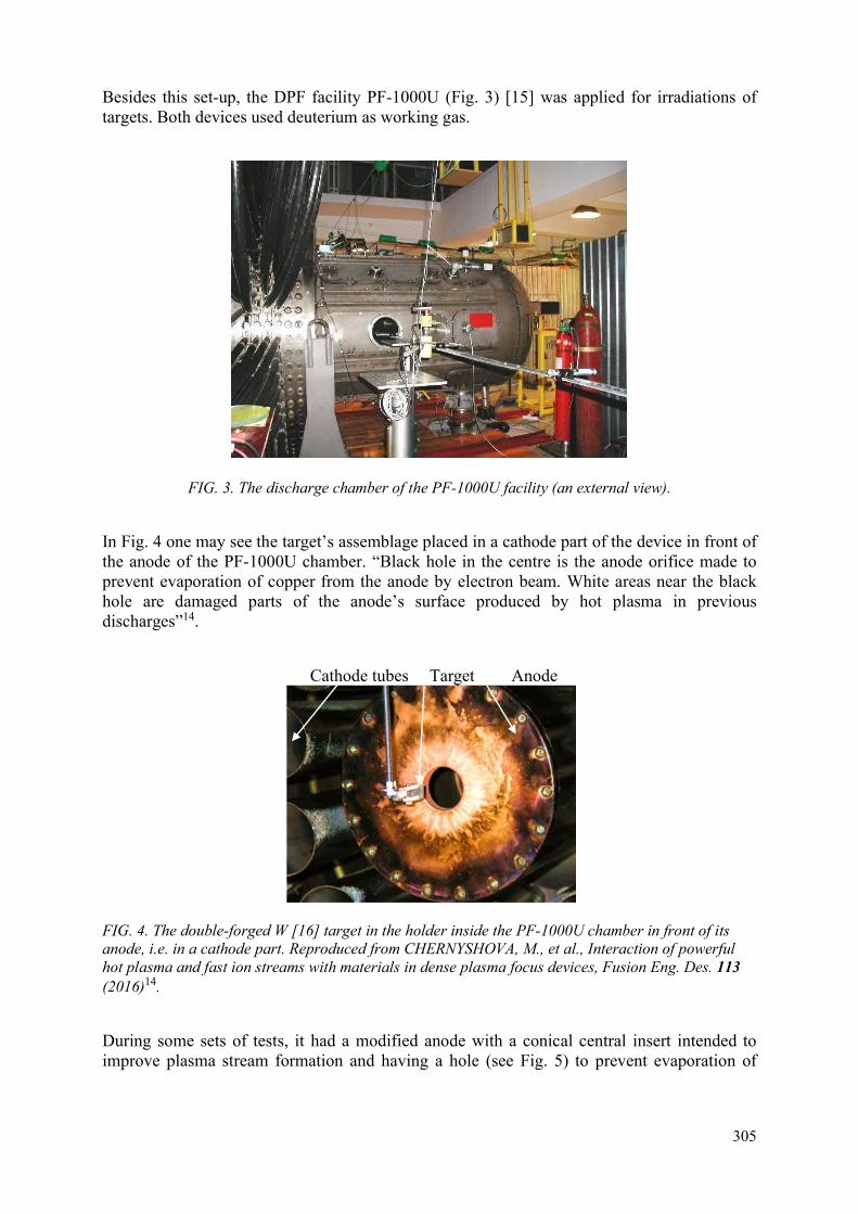
305
Besides this set-up, the DPF facility PF-1000U (Fig. 3) [15] was applied for irradiations of targets. Both devices used deuterium as working gas.
FIG. 3. The discharge chamber of the PF-1000U facility (an external view).
In Fig. 4 one may see the target’s assemblage placed in a cathode part of the device in front of the anode of the PF-1000U chamber. “Black hole in the centre is the anode orifice made to prevent evaporation of copper from the anode by electron beam. White areas near the black hole are damaged parts of the anode’s surface produced by hot plasma in previous discharges”14.
Cathode tubes Target Anode
FIG. 4. The double-forged W [16] target in the holder inside the PF-1000U chamber in front of its anode, i.e. in a cathode part. Reproduced from CHERNYSHOVA, M., et al., Interaction of powerful hot plasma and fast ion streams with materials in dense plasma focus devices, Fusion Eng. Des. 113 (2016)14.
During some sets of tests, it had a modified anode with a conical central insert intended to improve plasma stream formation and having a hole (see Fig. 5) to prevent evaporation of

306
copper (anode’s material) correspondingly during the radiation material science experiments. The holder of the tungsten target is shown in Fig. 6.
FIG. 5. The internal part of the chamber of the PF-1000U facility with the anode (a) having a conical insert with a hole in its central part, the cathode tubes (b), and the supporting rod (c) keeping a holder (d) of the target under irradiation.
(a) (b)
FIG. 6. A supporting rod (1), a holder (2) and a tungsten target (3) inside the PF-1000U chamber. (a) The virgin tungsten sample; (b) the same sample after irradiation.
After a number of conditioning shots on both devices they have started generating neutrons and hard X rays. Monitoring of current derivative of a discharge gave data on the eminence of the particular discharge. The “quality” of the discharge and the power of the ion beam were estimated by comparing a sharpness of the current derivative peak and the neutron yield correspondingly. Usually the neutron yield is observed by two methods – by using data obtained with a silver activation counter and by examination of oscilloscope traces of a time-resolved fast probe. This probe is based on a photomultiplier tube with a plastic scintillator (PMT+S), and it has temporal resolution about 2 ns. Fig. 7 presents current derivative of the discharge of the PF-6 device whereas Fig. 8 – signals of hard X rays and neutrons obtained with PMT+S.
a
b
c d
1
2 3
1
2
3

307
Investigations of the interaction processes of deuterium plasma streams and beams of fast deuterons with the targets under tests [3] have been provided in this case by integral in time photographing of the processes in a visible spectrum of light (the overall duration of the processes takes about a microsecond) during plasma irradiation and with laser interferometry (temporal resolution is determined by the laser pulse duration, which is 1 ns). Examples of pictures obtained by these two techniques are presented in Figs. 8 and 9 correspondingly.
(a) (b)
FIG. 7. Oscilloscope traces of the current derivatives of the discharges produced at the PF-6 device. (a) “bad” shot; (b) “good” shot.
X rays↑ ↑neutrons X rays↑ ↑neutrons
(a) (b)
FIG. 8. PMT+S oscilloscope traces of the discharges produced at the PF-6 device: (a) “bad” shot; (b) “good” shot.
During the tests, the specimens were placed on Z axis of DPF chambers perpendicular to it by their flat surface “(with one exception – see below) at small distances from the DPF anodes (see e.g. Fig. 5): in the PF-1000U these distances were 7 and 11.5 cm whereas in the PF-6 device they were 3.4 and 8 cm.
The devices PF-6 and PF-1000U generate very powerful pulses of hot dense (Tpl ~ 1 keV, npl ~ 1018 cm-3) deuterium plasma (HP) jets (velocity vpl ≥ 107 cm/s) with pulse durations τpl ~ 50 and 100 ns of maximal power flux densities on the target’s surface up to PHP ~ 109 and 1010 W/cm2 as well as fast ion (deuteron) streams (FIS) (deuterons’ energy Ed ~ 0.05–1.0 MeV) with pulse durations τd ~ 20 and 50 ns with maximal power flux densities right up to PFIS ~ 1011 W/cm2 and 1012 W/cm2 respectively. From these figures one may see that DPF may be a very well simulator of conditions taking place on the walls of FR with IPC. It is also able to model an initial phase (the most powerful one) of the Type-I ELMs effects (this phase haven’t been investigated in tokamaks with nanosecond time resolution yet but certainly it lasts shorter than 1 μs). At the same time the so-called “integral damage factor” (IDF) F = P×τ0.5 [19] provides
-8
-3
2
-0.5 0.5 1.5 2.5 3.5Time [µs]
dI/dt
-8
2
-0.5 0.5 1.5 2.5 3.5Time [µs]
dI/dt
-0.2
-0.15
-0.1
-0.05
0
0.05
0 200 400Time [ns] -0.16
-0.11
-0.06
-0.01
-100 100 300 500Time [ns]

308
(with certain reservations – see above) an opportunity to simulate the above-mentioned radiation loads (predictable for both reactors types) by the plasma/ion streams generated in DPF.
Indeed, a very high power flux density P of DPF compensates too short pulses (compared with those in FR with MPC) τ of HP and FIS (in FR with IPC pulse durations of irradiations are of the same order as in DPF). This IDF has restricted ranges of applicability – both in time intervals and in the ranges of power flux densities, but it was discussed above in the first paragraph of the paper.
With a special anode’s geometry of a DPF chamber an extraordinary regime of operation can extend heat load duration up to 30 µs in the PF-6 device and up to 100 µs in the PF-1000U facility correspondingly [20] that is comparable with the periods of tokamak emergency events. Also, it is very important to mention here that the heat loads in these experiments with DPF devices are produced just by streams of the same nature (hot plasma and fast ions) having parameters as expected on the first wall in the future FR modules (plasma temperature ~ 1 keV, fast ion energies ~ 0.1–1.0 MeV) in the FR of both types.
Distances from the anode to a specimen ensured almost the same maximal power flux density in both devices”14 – yet in the PF-6 on a much smaller area. Sample holders were constructed in a way that enabled to preserve the surface of the samples from any holder material redeposition upon them in a maximal extent (Figs 2, 4, and 6).
The “anodes of both devices have holes in the centre. This prevents the powerful relativistic electron beam (REB) (striking the anode’s surfaces) from evaporating the anode’s material (copper). During the devices’ operation the following parameters were monitored: current derivative by magnetic probes, full discharge current by Rogowski coil, neutron and X ray pulses by 6 photomultiplier tubes with scintillators (time resolution of this last technique was ≈ 2 ns, Figs 1(a) and 8), plasma dynamics visualization provided by time-integrated photographing in visual range, by 1 ns 4 frame self-luminescence and by 16-frame laser interferometry, absolute neutron yield using Ag, In, Y and Be activation counters, etc. Each sample was subjected to 1, 2, 4, 5, 8, and 16 consecutive shots”14.
Also, “for these experiments a new DPF device Vikhr’ has been put into operation by our colleagues at IMET RAS. Its front view with open discharge chamber fitted for material experiments are shown in Fig. 9 together with the oscilloscope traces taken for current derivatives for all 4 channels of the device”13.

309
(a) (b)
FIG. 9. The newly assembled “Vikhr’” device (IMET RAS. (a) Front view; (b) 4 oscilloscope traces of current derivatives measured at 4 capacitors. Ec =5.6 kJ; U0 = 20 kV; Idisch ≈ 500 kA. Reproduced from GRIBKOV, V., et al., Comparative analysis of damageability produced by powerful pulsed ion/plasma streams and laser radiation on the plasma-facing W samples, Radiation Physics and Chemistry 150 (2018)13.
It was implemented in parallel experiments with the PF-6, PF-1000U facilities (IPPLM, 2 kJ and 400 kJ) and with the Bora machine (ICTP, 5 kJ) [21]. Besides our previous results obtained at the device PF-5M (IMET RAS, 2 kJ), described in [22] are discussed in comparison with the current new data.
A single-cascade laser device GOS-1001 [23] “with flat resonator that is able to work in a free-running (FR) mode (P = 105–107 W/cm2, τ = 0.7 ms, individual spike duration ≈ 800 ns, off-duty factor 2-10 µs) or in a Q-spoiled (QS) regime (P = 109–1011 W/cm2, τ = 80 ns) was applied for the laser heating of a target in these two different regimes”13 (see Fig. 10).
(a) (b)
FIG. 10. (a) A laser device GOS-1001; (b) oscilloscope trace of a pulse in a free-running (FR) mode (τ = 0.7 ms, individual spike duration 0.8 µs, off-duty factor 2-10 µs). Reproduced from GRIBKOV, V., et al., Comparative analysis of damageability produced by powerful pulsed ion/plasma streams and laser radiation on the plasma-facing W samples, Radiation Physics and Chemistry 150 (2018)13.

310
3. MATERIALS, IRRADIATION CONDITIONS, ANALYSIS TECHNIQUES
The “samples for investigation were selected among materials counted as perspective ones for both types of FR. The main idea of the current experiments was to compare damageability of several types of mock-ups subjecting them to radiation loads that exceed the expected ones in FR with IPC”14. We investigated double-forged W supplied by the IAEA and investigated in FZJ, Germany [24] (later these specimens are named as DF “with numbers), tungsten manufactured in R.F. by powder metallurgy, composite material on its base with 1% addition of disperse particles of La2O3, aluminium, low-activated ferritic steel “Eurofer”, austenitic and ODS steels, Ti β-alloy”14, vanadium, different types of ceramics, and others.
“A number of analytical techniques were applied for investigation of the irradiated samples (both their surface layers (SL) and bulks of materials) before and after irradiation.
Among them classical optical and scanning electron microscopy as well as atomic emission spectroscopy were used to understand character and parameters of damageability of the sample surface layers. Atomic force microscopy was applied to measure surface roughness after irradiation”14. Tomographic atom probe was implemented for investigation of oxide particles in the irradiated ODS Eurofer [25]. X ray structure and elemental analysis, weighing of specimens as well as measurements of their micro-(nano-) hardness were applied before and after irradiation. Surface layers (SL) and metallographic sections of our samples were investigated by Scanning Electron Microscopy (SEM) (using the microanalyzer EVO 40) and by Atomic Emission Spectroscopy (AES) (using a glow discharge spectrometer SA-2000, “LECO” company). Some results obtained through application of the above-mentioned techniques are presented below.
The main material for current testing was double forged tungsten manufactured in Julich, Germany [24]. “Size of samples was 12×12×5 mm3.
Irradiation of the samples at PF-1000U, PF-6, Bora, PF-5M and Vikhr’ has been provided by hot deuterium (or hydrogen sometimes) plasma streams (HPS) at the power flux densities of PHPS = 108-10 W/cm2 with typical pulse durations 50–100 ns and by fast ions (deuterons) beams with energy of particles Ei ≥ 100 keV at power flux densities in the range PFIS ~ 108–1012 W/cm2 with typical pulse durations 10–50 ns depending on the particular device.
Because of geometrical factors connected with the sizes of the devices the above-mentioned values of P (in particular for fast ion streams) in small devices has been realized on minor areas of the targets with the characteristic sizes about Ø ~ 0.1-0.4 cm whereas at the big facility PF-1000U the whole irradiated surface was about tens cm2.
Experiments on interaction of laser radiation (LR) with materials have been provided in air by using a laser GOS-1001 in the above-mentioned two modes of operation – in a free-running (FR) mode and in a Q-switched (QS) regime.
In the first mode we mainly used for irradiation PLR ≈ 3×10⁵ W/cm2 with the overall pulse duration 0.7 ms, focal spot d ≈ 0.6 cm (defocused laser irradiation), and another regime with PLR ≈ 3×10⁶ W/cm2 with the same overall pulse duration 0.7 ms, but with focal spot d ≈ 0.2 cm (relatively sharp focusing of laser radiation).
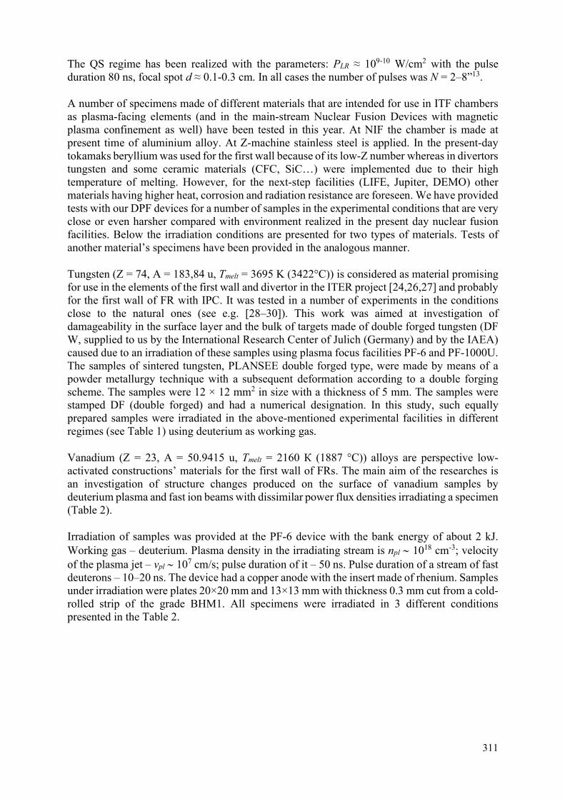
311
The QS regime has been realized with the parameters: PLR ≈ 109-10 W/cm2 with the pulse duration 80 ns, focal spot d ≈ 0.1-0.3 cm. In all cases the number of pulses was N = 2–8”13.
A number of specimens made of different materials that are intended for use in ITF chambers as plasma-facing elements (and in the main-stream Nuclear Fusion Devices with magnetic plasma confinement as well) have been tested in this year. At NIF the chamber is made at present time of aluminium alloy. At Z-machine stainless steel is applied. In the present-day tokamaks beryllium was used for the first wall because of its low-Z number whereas in divertors tungsten and some ceramic materials (CFC, SiC…) were implemented due to their high temperature of melting. However, for the next-step facilities (LIFE, Jupiter, DEMO) other materials having higher heat, corrosion and radiation resistance are foreseen. We have provided tests with our DPF devices for a number of samples in the experimental conditions that are very close or even harsher compared with environment realized in the present day nuclear fusion facilities. Below the irradiation conditions are presented for two types of materials. Tests of another material’s specimens have been provided in the analogous manner.
Tungsten (Z = 74, A = 183,84 u, Tmelt = 3695 K (3422°C)) is considered as material promising for use in the elements of the first wall and divertor in the ITER project [24,26,27] and probably for the first wall of FR with IPC. It was tested in a number of experiments in the conditions close to the natural ones (see e.g. [28–30]). This work was aimed at investigation of damageability in the surface layer and the bulk of targets made of double forged tungsten (DF W, supplied to us by the International Research Center of Julich (Germany) and by the IAEA) caused due to an irradiation of these samples using plasma focus facilities PF-6 and PF-1000U. The samples of sintered tungsten, PLANSEE double forged type, were made by means of a powder metallurgy technique with a subsequent deformation according to a double forging scheme. The samples were 12 × 12 mm2 in size with a thickness of 5 mm. The samples were stamped DF (double forged) and had a numerical designation. In this study, such equally prepared samples were irradiated in the above-mentioned experimental facilities in different regimes (see Table 1) using deuterium as working gas.
Vanadium (Z = 23, A = 50.9415 u, Tmelt = 2160 К (1887 °C)) alloys are perspective low-activated constructions’ materials for the first wall of FRs. The main aim of the researches is an investigation of structure changes produced on the surface of vanadium samples by deuterium plasma and fast ion beams with dissimilar power flux densities irradiating a specimen (Table 2).
Irradiation of samples was provided at the PF-6 device with the bank energy of about 2 kJ. Working gas – deuterium. Plasma density in the irradiating stream is npl 1018 cm-3; velocity of the plasma jet – vpl 107 cm/s; pulse duration of it – 50 ns. Pulse duration of a stream of fast deuterons – 10–20 ns. The device had a copper anode with the insert made of rhenium. Samples under irradiation were plates 20×20 mm and 13×13 mm with thickness 0.3 mm cut from a cold-rolled strip of the grade ВНМ1. All specimens were irradiated in 3 different conditions presented in the Table 2.

312
TABLE 1. IRRADIATION REGIMES FOR W SAMPLES IN PF-1000U AND PF-6 DEVICES13,14
Irradiation facility
Parameters and operating modes used Value
Plasma focus PF-6
Deuterium plasma density, npl, cm–3 Plasma flow velocity, cm/s
Power flux density of plasma flow on the target’s surface, qpl, W/cm2
Duration of the plasma flow pulse, τpl, ns Power flux density of the fast ion beam (Ei ≥ 100
keV) on the target’s surface, qfi, W/cm2 Pulse duration of the fast ion beam flux, τfi, ns
Distance from anode to sample, mm Discharge current, I, kA
1018–1019 up to 3 × 10⁷
109–1010 50
1010–1011
10-50 34
≤ 340
Plasma focus PF-1000U
Deuterium plasma density (working gas D2), npl, cm–
3 Plasma flow velocity, Vpl, cm/s
Power flux density of the plasma stream on the target’s surface, qpl, W/cm2
Duration of the plasma stream pulse, τpl, ns Power flux density of the fast ion beam (Ei ≥ 100
keV) on the target’s surface, qfi, W/cm2 Pulse duration of the fast ion beam, τfi, ns
Discharge current, I, MA Sample position
Distances from the anode surface, mm (i.е. the
sample was immersed inside the pinch (hot plasma column) having a length of about ~100 mm)
1018–1019 up to 3 × 10⁷
109–1010 50-100
1011–1012
10-50 ≤ 2.0
Normal to the plasma flow
70
and 150
TABLE 2. EXPERIMENTAL CONDITIONS OF IRRADIATION OF VANADIUM AT THE PF-6 DEVICE13,14
No. of samples
Zone (according to a distance from
the anode)
Name of a sample
Distance from the
anode
Number of
pulses
Power flux density of
plasma stream, q, W/cm2
Power flux density of fast
ion stream, q, W/cm2
1 I V1 3,5 2 1010 1012 2
II
V4 8 1
108-109 1010-1011 3 V5 8 2 4 V6 8 4 5 V7 8 8 6
III
V2 13 2
107 108
7 V3 13 4 8 В7 13 1 9 В8 13 6 10 В9 13 12 11 V-II 13 21

313
4. INVESTIGATIONS OF THE PHYSICAL PROCESSES OF PLASMA-WALL INTERACTION TAKING PLACE AT IRRADIATIONS OF MANUFACTURED TARGETS OF DIFFERENT MATERIALS FOR APPLICATIONS IN NUCLEAR FUSION REACTORS
Fig. 11 shows the following sequence of images of the irradiation procedure: the “1 ns self-luminescence image of the pinch (line A – anode’s surface) at its maximal compression, Fig. 11(a), the 1-ns interferometric plasma images (IPI) at the beginning of the first compression without a target, Fig. 11(b), IPI with a target during its irradiation by hot plasma (HP) jets followed by secondary plasma (SP) formation after the target irradiation, Fig. 11(c), IPI with a target after its irradiation by a powerful stream of fast ions (FIS) with a well-developed secondary plasma, Fig. 11(d), and IPI of the late stage of the target irradiation with an unloading (rarefaction) wave (UW) in front of the target (the part of the cloud adjacent to the target’s surface and non-transparent for laser light) and a shock wave (SW) on the back side of the target, Fig. 11 (e) (PF-1000U device)”14.
↑Z Pinch ↑Z SP ↑Z Target ↑Z UW SW ↑Z
A (a) (b) (c) (d) (e)
FIG. 11. (a) The 1-ns self-luminescence image of the pinch at its maximal compression; (b) the interferometric plasma image (IPI) at the beginning of the first compression without a target; (c) the IPI of the DPF with a target at the beginning of its irradiation; (d) the well-developed secondary plasma after the target irradiation by FIS; (e) the late stage of the target irradiation with unloading (rarefaction) wave in front of the target and a shock wave behind the back side of the target. Line “A” represents the anode’s surface. Reproduced from CHERNYSHOVA, M., et al., Interaction of powerful hot plasma and fast ion streams with materials in dense plasma focus devices, Fusion Eng. Des. 113 (2016)14.
The “target was a large ferritic steel plate (2-mm thick) placed at a distance of 11.5 cm from the anode lid perpendicular to Z axis. Therefore, streams of hot plasma (HP) and fast ions (FIS) irradiated it normally to its surface layer (SL). Measurements of the boundary expansion speed in case (d) – vpl = 2 × 107 cm/s – gave us the temperature estimation [20] of the SP cloud for steel: Tsp ≥ 100 eV.
As it is depicted in Figs 12(b)–(d) of an interferometric picture Fig 12(a) gives the beginning of the secondary plasma production. There are some restrictions implied on the upper limit of measurable electron density here [20]. It is important to mention that the IPI of the later stages when the secondary plasma is well-developed (case Fig. 12(d)) cannot be processed for two reasons: interferometric fringes are condensed too much and, consequently, cannot be distinguished from each other; plasma boundaries spread outside the optical window (interferometric frame) that is not allowed to measure a fringe shift”14.

314
↑Anod↑Pinch↑Target (a) (b) (c) (d)
FIG. 12. (a) IPI of the secondary plasma propagating in the opposite direction to the movement of the primary plasma stream; (b) lines of constant density; (c, d) the IPI processing are showing the 3D electron density distribution for later stage than in the case of the image. Target – 2-mm ferritic steel sheet; PF-1000U facility. Reproduced from CHERNYSHOVA, M., et al., Interaction of powerful hot plasma and fast ion streams with materials in dense plasma focus devices, Fusion Eng. Des. 113 (2016)14.
Investigations of the interaction processes of deuterium plasma streams and beams of fast deuterons with the targets under tests have been provided also by the in-time integral photographing of the processes in a visible spectrum of light (the overall duration of the processes takes about a microsecond) during plasma irradiation provided in parallel with laser interferometry (temporal resolution is determined by the laser pulse duration, which is 1 ns). Examples of pictures obtained by these two techniques are presented in Figs 13–14 correspondingly. It was done with the anode configuration shown in Fig. 5.
(a) (b)
(c)
1 - Primary deuterium plasma 2 - Secondary tungsten plasma 4 - Anode 3 - Shock-wave front in deuterium plasma
1 2
3

315
FIG. 13. (a, b, c) Three pictures of time-integrated plasma luminescence images obtained in a visible range of radiation with a primary deuterium plasma torch (1) formed near the anode (4), a secondary tungsten plasma cloud (2), and a shock-wave front in deuterium plasma (3) formed at spreading of a secondary tungsten plasma “plunger”. Note at the Fig. 8(b) two shock fronts produced very likely by two lines “burnt out” in different moments of time at dissimilar temperatures.
In Figs 13 (a)–(c), besides luminescence of primary deuterium plasma (1) located near the anode’s conical insert (4) on the right-hand side of the pictures one may clearly see a light emission produced by a cloud of secondary tungsten plasma (2) in front of the target – on the left-hand side of the image near the target’s holder. It has a hemispherical shape, and it is evident that this secondary plasma bunch is spreading in the direction opposite to the movement of the primary plasma stream.
Moreover, one may also observe a shock-wave front (also of a hemispherical shape) (3) distinctly seen ahead of the secondary plasma cloud at a distance from a target of about two times larger compared with the size of the secondary plasma bunch luminescence.
At first sight it seems strange – the photograph is an integral over time. Why it looks as an instant print? Such pictures were observed in our previous experiments also in soft X ray range of radiation of the pinch plasma [31]. It was found there by spectroscopic investigations that certain line emission that is higher by intensity compared with bremsstrahlung background and much shorter by time duration (because of fast “burn-out” of the corresponding ionization stage) is able to produce such an effect. It takes place here at pushing of deuterium gas (plasma) by a secondary tungsten plasma “plunger” spreading from the target surface. This fact testifies a high temperature of secondary plasma [20].
The 16-frame interferometric methodology (1-ns laser pulse duration and 20 to 30 ns time intervals between frames) gives an opportunity to measure a velocity of expansion of the secondary plasma edge in the direction from the target (Fig. 14). It allows in its turn to estimate an initial temperature of plasma in the secondary plasma cloud [20]. This method has shown that the temperature appears to be of the order of 100 eV. This figure is supported by the observation of a shock wave from this cloud within a deuterium plasma torch (Figs 13–14). Discontinuities and specificity in the primary pinch plasma column (Fig. 14(f)) are evidenced the fact that this secondary tungsten plasma cloud is produced namely by a powerful stream of fast deuterons [20].

316
(a) (b)
(c) (d)
(e) (f)
FIG. 14. (a, b) Laser interferometric pictures (1-ns time resolution) showing the process of spreading of the primary deuterium plasma to the tungsten specimen; (c) the event of collecting of it near the target surface (d, e, f) a creation of the secondary tungsten plasma cloud near the target’s surface and its expansion in the direction opposite to the movement path of the primary deuterium plasma stream.
W target
Deuterium pinch
(primary) plasma
Anode Anode
W target
W target
Secondary tungsten plasma
Anode Anode
Anode Anode

317
5. RESULTS AND DISCUSSIONS
5.1. DPF action upon materials
After producing irradiations of samples of the above-mentioned materials with a different number of pulses, an analytical investigation of the specimens “were carried out. Fig. 15 depicts SEM images of the surface of the ferritic steel “Eurofer” – virgin (Fig. 15(a)), after 1 shot (Fig. 15(b)) and after 5 shots (Fig. 15(c)) of the PF-6 device. A wave-like structure of the surface with initial traces of the micro cracks nucleation (Fig. 15(b)) is observed after 1 shot of the PF-6 device. A strongly developed wave-like structure of the surface of the same material melted with a fracturing pattern and pores (Fig. 15(c)) becomes apparent after 5 shots of the same device produced under similar conditions as in the case of Fig. 15(b). The characteristic wavelength of the wave-like structure is about a hundred µm”14.
(a) (b) (c)
FIG. 15. SEM images of the stainless steel “Eurofer”. (a) Virgin material; (b) after 1 shot of PF-6; (c) after 5 shots of PF-6.
“After 8 pulses and in zones of the maximal power flux densities the damage of the ferritic steel surface acquires a new feature (see Fig. 16, PF-6, 8 shots, zone of the FIS action). The material in this case was melted after irradiation during the action of the secondary plasma. In addition to the same types of damageability as depicted in Fig. 14b and c one may observe a number of bubbles (Fig. 16(b)) with broken covers (Figs 16(c)–(d)). In this case, the bubbles’ diameters typically range from 100 μm down to less than 10 μm”14.
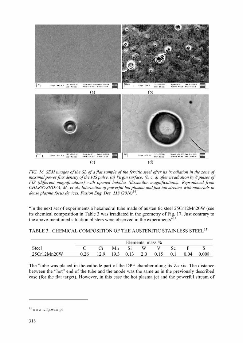
318
(a) (b)
(c) (d)
FIG. 16. SEM images of the SL of a flat sample of the ferritic steel after its irradiation in the zone of maximal power flux density of the FIS pulse. (a) Virgin surface; (b, c, d) after irradiation by 8 pulses of FIS (different magnifications) with opened bubbles (dissimilar magnifications). Reproduced from CHERNYSHOVA, M., et al., Interaction of powerful hot plasma and fast ion streams with materials in dense plasma focus devices, Fusion Eng. Des. 113 (2016)14.
“In the next set of experiments a hexahedral tube made of austenitic steel 25Cr12Mn20W (see its chemical composition in Table 3 was irradiated in the geometry of Fig. 17. Just contrary to the above-mentioned situation blisters were observed in the experiments”14.
TABLE 3. CHEMICAL COMPOSITION OF THE AUSTENITIC STAINLESS STEEL15
Steel
Elements, mass % C Cr Mn Si W V Sc P S
25Cr12Mn20W 0.26 12.9 19.3 0.13 2.0 0.15 0.1 0.04 0.008
The “tube was placed in the cathode part of the DPF chamber along its Z-axis. The distance between the “hot” end of the tube and the anode was the same as in the previously described case (for the flat target). However, in this case the hot plasma jet and the powerful stream of
15 www.ichtj.waw.pl

319
fast ions stroke together only the internal tube surface because the most powerful part of the beam of fast ions at this distance from the anode was propagated inside the angle of about 7°”14.
FIG. 17. The layout drawing of the austenitic tube positioning inside the PF-1000U chamber. Reproduced from CHERNYSHOVA, M., et al., Interaction of powerful hot plasma and fast ion streams with materials in dense plasma focus devices, Fusion Eng. Des. 113 (2016)14.
“The outer surface of the tube was irradiated mainly by a stream of HP. Both streams (HP and FIS) irradiated the SLs of the tube tangentially. Because of this geometry the values of power flux densities of HP and FIS on both surfaces were in this case about 1–2 orders of magnitude lower compared with the flat target oriented perpendicular to the streams. 4 pulses have been provided (i.e. 2 times less compared with the flat sample of the ferritic steel). Blisters here were of smaller sizes (lower than 1.0–0.1 μm – see Fig. 18) in relation to the above bubbles”14.
(a) (b)
FIG. 18. (a) Blisters observed on the internal surface of the austenitic steel tube at its “hot” side (SEM); (b) concentration distribution of deuterium and oxygen in the material’s depth: 1 – deuterium on the internal surface, 2 – deuterium on the external surface, 3 – oxygen on the internal surface, 4 – oxygen on the external surface of the tube (data obtained by the atomic emission spectroscopy). Reproduced from CHERNYSHOVA, M., et al., Interaction of powerful hot plasma and fast ion streams with materials in dense plasma focus devices, Fusion Eng. Des. 113 (2016)14.
In principle, at least 3 reasons may result in bubbles formation on a “surface layer: boiling of basic material, evaporation of light components of alloys (e.g. manganese within a stainless
1 μm

320
steel specimen) and implantation of the ions of the working gas (hydrogen isotopes) into the first-wall material – blisters in the true sense.
The surface layers and metallographic sections of the samples were investigated by SEM and by AES. The blisters appeared in the “hot” part of the tube facing the anode of the chamber. In this case the blisters are not opened (Fig. 18(a)).
A remarkably higher concentration of deuterium in the internal part of the tube compared with its content in the external nanolayer (Fig. 18(b)) was observed.
Presence of deuterium in the nanolayers under investigation supports the fact that after pulsed penetration through the specimen’s surface, deuterium was never fully eliminated from it by evaporation or diffusion. On the contrary, deuterium was preserved inside the crystal lattice and in blisters. Interestingly, chemical interaction of implanted deuterium with interstitial atoms of the specimen’s impurities is very unlikely under these circumstances due to a low level of bond energy between the deuterons and these elements [32–34]. The same fact relates to oxygen that was presented in the DPF chamber as an impurity element in the working gas.
As a matter of fact, deuterons may have been partially diluted inside the lattice or captured by trapping centres. In the first case, atoms of deuterium left the SL very fast via a diffusion process through an irradiated surface into the chamber volume or into the bulk of the material. The trapping process of atoms was very likely accompanied by creation of vacancy complexes (binding energy of hydrogen with vacancy in iron is 0.5 eV, with the vacancy cluster, 0.7–0.8 eV) [34].
On the other hand, deuterium was trapped by means of interactions of deuterons with lattice defects of the type of atoms of impurities, pores, oxycarbonitride particles present in the material, e.g. the binding energy of the hydrogen atom with the interstitial atoms of carbon and oxygen is within the limits 0.05-0.08 eV [33, 34]. It is highly probable that binding energy of a deuterium atom is within the same spectrum.
At the same time according to theoretical calculations [35] the binding energy of hydrogen atom with impurity interstitial atoms (Не, С, N, О) is noticeably higher but still not exceed 0.2 eV. This figure is several times less compared with the binding energy of hydrogen atom with vacancies or vacancy clusters in iron.
Subsequent sequential pulsed actions of the energy streams upon the tube’s material resulted again in explosion-like melting, partial evaporation and boiling of the liquid phase of the SL. Deuterium atoms (implanted in previous shots) present in the specimens together with extrinsic oxygen and carbon contributed to yielded gas inclusions – bubbles [36] inside the melted volume. Some of them escaped through the free surface whereas others implanted mainly into the nanolayers and deeper parts of the irradiated tube”14.
Fig. 19 presents optical microscopic pictures of the surfaces of tungsten samples manufactured by powder technology in R.F. Fig. 19 (a) and specimens of the DF type (Figs 19 (b)–(d) samples DF35, DF37 and DF38) [24] after their irradiation in the PF-1000U facility by 2 (Figs 19(a)–(b), Figs 19(c)–(d) sequential pulses. Figs 19(e)–(f) are SEM images of a part of the area of DF specimen Fig. 19(d).
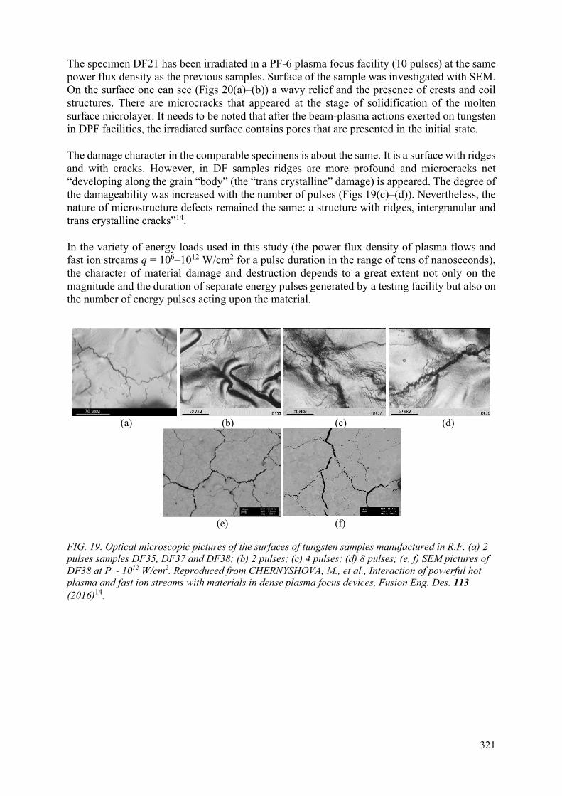
321
The specimen DF21 has been irradiated in a PF-6 plasma focus facility (10 pulses) at the same power flux density as the previous samples. Surface of the sample was investigated with SEM. On the surface one can see (Figs 20(a)–(b)) a wavy relief and the presence of crests and coil structures. There are microcracks that appeared at the stage of solidification of the molten surface microlayer. It needs to be noted that after the beam-plasma actions exerted on tungsten in DPF facilities, the irradiated surface contains pores that are presented in the initial state.
The damage character in the comparable specimens is about the same. It is a surface with ridges and with cracks. However, in DF samples ridges are more profound and microcracks net “developing along the grain “body” (the “trans crystalline” damage) is appeared. The degree of the damageability was increased with the number of pulses (Figs 19(c)–(d)). Nevertheless, the nature of microstructure defects remained the same: a structure with ridges, intergranular and trans crystalline cracks”14.
In the variety of energy loads used in this study (the power flux density of plasma flows and fast ion streams q = 106–1012 W/cm2 for a pulse duration in the range of tens of nanoseconds), the character of material damage and destruction depends to a great extent not only on the magnitude and the duration of separate energy pulses generated by a testing facility but also on the number of energy pulses acting upon the material.
(a) (b) (c) (d)
(e) (f)
FIG. 19. Optical microscopic pictures of the surfaces of tungsten samples manufactured in R.F. (a) 2 pulses samples DF35, DF37 and DF38; (b) 2 pulses; (c) 4 pulses; (d) 8 pulses; (e, f) SEM pictures of DF38 at P ~ 1012 W/cm2. Reproduced from CHERNYSHOVA, M., et al., Interaction of powerful hot plasma and fast ion streams with materials in dense plasma focus devices, Fusion Eng. Des. 113 (2016)14.

322
FIG. 20. SEM image of the irradiated surface of DF W sample DF21 exposed in a PF-6 plasma focus facility (10 pulses).
In general, the nature of the material destruction is of shock-wave and thermal-fatigue character. Microcracks appear in the irradiated layer and propagate both parallel to the irradiated surface and at an angle to the surface. In all cases there is a rupture of the material and the formation of microcracks parallel to the surface and wedge-shaped ones on the boundaries of the blocks.
Results of the precise weighing of the samples having equal areas (1×1 cm2) of their irradiation are presented in Table 4. As depicted in the table, the average mass loss in both cases (FZJ and IMET samples) was decreased. This change is about 0.01 0.002 g/shot.
TABLE 4. MASS CHANGE AFTER IRRADIATION OF W SAMPLES14
No. of a sample Mass before irradiation
Mass after irradiation
Number of irradiation pulses
Mass change
DF38 (FZJ) 13.0453 12.9564 8 - 0.0889 DF39 (FZJ) 12.8765 12.8329 4 - 0.0436 No. 1 (IMET) 28.6880 28.6280 8 - 0.060
However, in parallel with “erosion process the total mass of the sample is influenced also by the redepositing of different elements of the DPF chamber and cathode material upon the sample’s surface as it was found after irradiation (see Fig. 21 – elemental analysis of the sample DF9). The same processes (redepositing of materials and absorption of hydrogen isotopes) take place in fusion reactors”14. Thus, the data presented in the Table 4 reflect both processes – mass loss and mass increase, so the data represent the relative mass changes – not the absolute ones. However, one may see that in this case evaporation was dominated over the redepositing.

323
FIG. 21. Elemental analysis of the tungsten DF9 sample after its irradiation by 8 pulses.
A comparative study was also conducted for the samples of the “tungsten composite of the following type: W-1%La2O3, i.e. tungsten with addition of dispersed particles of La2O3. Interest in this material is connected with its easier machinability in comparison with pure tungsten”14.
Fig. 22 depicts images of this sample’s surface layer (SL) irradiated also in the PF-1000U facility as for the DF9 specimen by 8 shots and at the same distance as above for the DF tungsten sample. These images are as follows: after its analysis by SEM (Fig. 22(a)), in secondary electrons (Fig. 22(b)) and in some characteristic lines (Figs 22(c)–(e)).
(a) (b) (c)
(d) (e)
FIG. 22. (a) SEM images of the W-1%La2O3 target after its irradiation in the PF-1000U facility; (b) images in secondary electrons (c) characteristic line radiations of La; (d) C; (e) O.
Inte
nsit
y (a
.u.)

324
Microstructure of the SL contains “cracks and porosity. In proximity to cracks, the material tends to peel. Pictures of the same part of the sample scanned in the characteristic line radiation for elements La, O, and C show their higher concentrations in lighter zones”14.
Then the titanium alloy NR4 of the type β-alloy Ti – V – Cr, bbc lattice, has been “irradiated in the PF-6 device. The sample was placed at the distance of 3.4 cm from the anode and it has been subjected by 5 pulses. The β-alloy of titanium is a complex doped high-strength alloy. It contains V, Cr, Fe, Mo, Sn, Si, and Al. Initial elemental content of the SL of the Ti alloy sample is presented in Table 5”14. The remnant is titanium.
TABLE 5. INITIAL ELEMENTAL CONTENT OF THE SL OF THE SAMPLE OF THE TITANIUM β-ALLOY14
Element Atomic number Norm. concentration [wt. %] V 23 18 Cr 24 7 Fe 26 1.5 Mo 12 5 Sn 50 1.5 Al 13 0.5 O 8 n/a Si 14 1.5
Fig. 23(a) depicts the SEM image of the surface layer of the β-alloy of titanium after irradiation. One may see that damageability bears about the same character as for tungsten and tungsten composite: macro cracks have approximately the same size in all 3 cases, and a thin net of cracks are observed in between. Fig. 23(b) is the X ray elemental analysis investigations of the Ti alloy sample NR4 in the area 8 after its irradiation in the PF-6 device.
(a) (b)
FIG. 23. (a) SEM analysis; (b) X ray elemental analysis investigations of the Ti alloy sample NR4 (area 8) after its irradiation in the PF-6 device.
“Elemental contents of the SL of the Ti alloy specimen in zones 8 (typical sample area across the surface) and 7 (black spot of the size ~ 10 μm that differs from surrounding areas) after its irradiation are presented”14 in Tables 6 and 7 and in Fig. 24. The remnant is titanium.
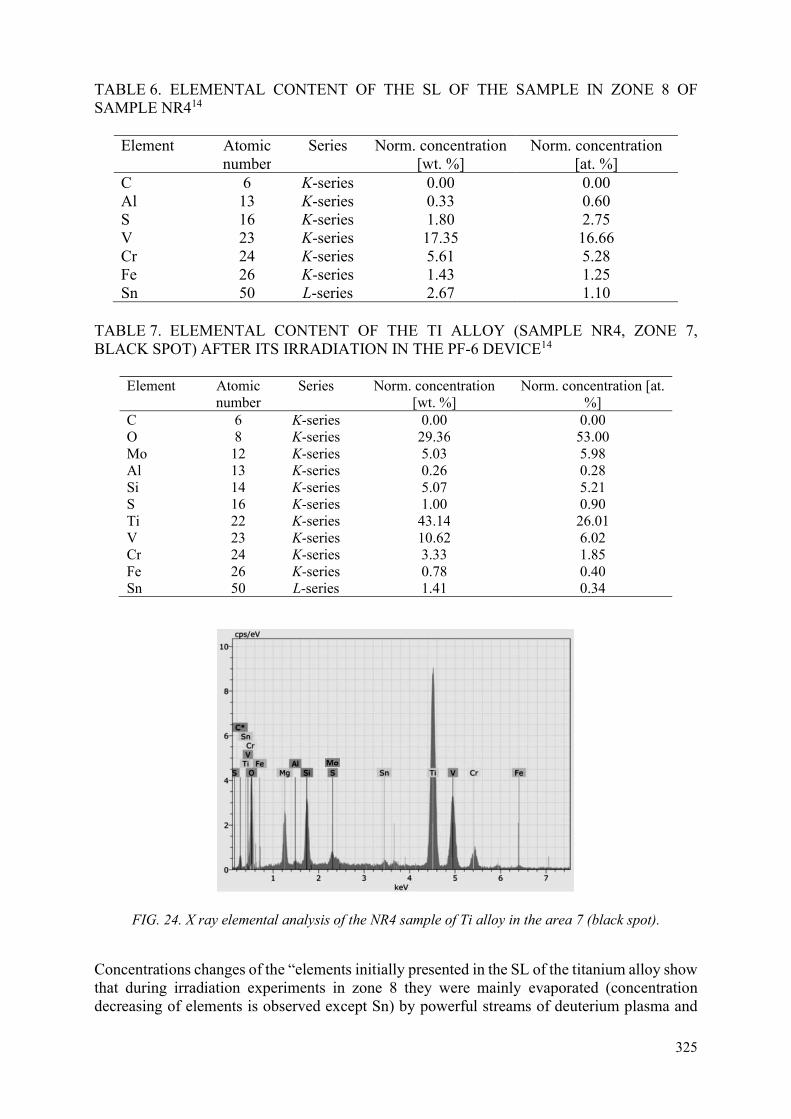
325
TABLE 6. ELEMENTAL CONTENT OF THE SL OF THE SAMPLE IN ZONE 8 OF SAMPLE NR414
Element Atomic number
Series Norm. concentration [wt. %]
Norm. concentration [at. %]
С 6 K-series 0.00 0.00 Al 13 K-series 0.33 0.60 S 16 K-series 1.80 2.75 V 23 K-series 17.35 16.66 Cr 24 K-series 5.61 5.28 Fe 26 K-series 1.43 1.25 Sn 50 L-series 2.67 1.10
TABLE 7. ELEMENTAL CONTENT OF THE TI ALLOY (SAMPLE NR4, ZONE 7, BLACK SPOT) AFTER ITS IRRADIATION IN THE PF-6 DEVICE14
Element Atomic number
Series Norm. concentration [wt. %]
Norm. concentration [at. %]
С 6 K-series 0.00 0.00 O 8 K-series 29.36 53.00 Mo 12 K-series 5.03 5.98 Al 13 K-series 0.26 0.28 Si 14 K-series 5.07 5.21 S 16 K-series 1.00 0.90 Ti 22 K-series 43.14 26.01 V 23 K-series 10.62 6.02 Cr 24 K-series 3.33 1.85 Fe 26 K-series 0.78 0.40 Sn 50 L-series 1.41 0.34
FIG. 24. X ray elemental analysis of the NR4 sample of Ti alloy in the area 7 (black spot).
Concentrations changes of the “elements initially presented in the SL of the titanium alloy show that during irradiation experiments in zone 8 they were mainly evaporated (concentration decreasing of elements is observed except Sn) by powerful streams of deuterium plasma and
326
fast deuterons. An increase of Ti concentration here is explained namely by “washing-out” of these elements having low melting temperature (like Mo that disappeared at all).
Although virgin material did not contain the elements S, Mg and O, which were found after irradiation (see Tables 6 and 7). However, these materials existed in the construction and functional elements of the working chamber of PF-6 device: oxygen and sulphur were the impurity components of corrosion-resistant steel Cr16N10T that was used for the working chamber of the facility and for its cathode’s cylinder. In addition, diagnostic windows, insulator and special target holder (placed inside the DPF chamber) contained S, Mg and Si that may be redeposited on the sample. Appearance of S in a SL observed all over the samples (see zone 8 in Fig. 23 and Table 5) was realized mainly by ion-atomic mechanism.
On the other hand, Mg, Si and O present only as separate inclusions viewed as dark spots (see Region 7 in Fig. 23 and Table 7). It indicates that these materials were very likely evaporated by a cluster mechanism and captured by the surface of our specimen as separate particles (droplets with dimensions from one till tens of micrometres). In particular it is related to oxygen because there is a high affinity between titanium and oxygen [37, 38]. Taking into account a very high concentration of oxygen in these particles (see Table 7) we may assume that these droplets represent the complicated oxides”14.
5.2. Laser influence upon materials
In Figs 25(a)–(b) two SEM images of tungsten samples “irradiated by laser light in a FR mode (a) and (b) at power flux density 3×10⁵ W/cm2 are presented.
One may see multiple craters having dimensions about 1–4 µm and cracks with length up to 20 µm. Figs 25(c)–(d) presents a comparison of SEM microphotography of W specimen irradiated by LR in a FR mode but at higher power flux density (PLR = 3×10⁶ W/cm2) with tungsten sample that has been irradiated in the Vikhr’ device at much higher power – PDPF ~ 1010 W/cm2. Difference in the pictures related to the LR for two regimes (two values of power flux density) is mainly in the size of the above-mentioned defects: at higher power flux density they have larger dimensions.
One may see a certain similarity of all pictures for LR and of DPF actions in Fig. 25 in spite of noticeable different values of P, very diverse pulse durations, rather dissimilar F (an order of magnitude) and various numbers of pulses N. In both regimes processes of partial evaporation, melting and crystallization of SL were observed.
They are accompanied by a creation of a wave-like relief, droplets structures and microcracks”13. The microcracks are directed as in parallel to the surface so at a certain angle to it into the depth, developing mainly along the borders of grains.
However, analysis has shown that the microcracks created by LR with long pulse durations had higher sizes compared with those produced by plasma/ion irradiation in the DPF (with the short ones). Their length and width are increased with growing of N and may reach of several hundred µm.

327
(a) (b)
(c) (d)
FIG. 25. (a, b )SEM microphotography images of two areas of the SL of W samples in zones of LR action in the FR mode: N = 8, τ = 0.7 ms, P = 3×10⁵ W/cm2; (c) SEM microphotography of areas of the SL of W samples: in zones of LR action in the FR mode: N = 8, τ = 0.7 ms, PLR = 3×10⁶ W/cm2; (d) after irradiation in the PF-6 device: N = 4, τ = 20/100 ns, PDPF ~ 1010 W/cm2. Reproduced from GRIBKOV, V., et al., Comparative analysis of damageability produced by powerful pulsed ion/plasma streams and laser radiation on the plasma-facing W samples, Radiation Physics and Chemistry 150 (2018)13.
In Fig. 26 “one may see SEM micrographs of another zone of a tungsten sample with different magnifications after its irradiation by LR in a FR mode with the same power flux density as in the previous case: PLR = 3×10⁶ W/cm2 and N = 8. These pictures demonstrate additional feature of the damageability produced by laser radiation in a FR mode compared with the irradiation of W in a DPF device. Namely, craters that are observed in this case has a very large dimensions whereas they are absent in the experiments with DPF at the conditions”13 of Fig. 25.
10 µm 10 µm

328
(a) (b)
(c) (d)
FIG. 26. (a) SEM microphotographs of W surface after an action of LR working in a FR mode; (b) with craters A, B and C shown with dissimilar magnification; (c) submicron structures; (d) submicron structures observed in zone C. PLR = 3×10⁶ W/cm2, N = 8. Reproduced from GRIBKOV, V., et al., Comparative analysis of damageability produced by powerful pulsed ion/plasma streams and laser radiation on the plasma-facing W samples, Radiation Physics and Chemistry 150 (2018)13.
In the previous experiment with PF-5M device [39] “functioning in softer regime of the DPF operation at power flux density much lower compared with the conditions presented in Fig. 25 (at P ~ 107–108 W/cm2 for both plasma and fast ion streams of the PF-5M) blisters were produced. In that case a gas phase of the blisters contains the implanted hydrogen as well as volatile compounds of hydrogen isotopes with elements of impurities (C, N, O) existed in virgin material.
Contrary to that in our present case of the LR action streams of hydrogen ions are absent. Moreover, in Fig. 26(b) one may see finer craters of secondary and tertiary generation existing inside the large craters. Note that defects in the form of craters were also observed in the case of plasma irradiation of tungsten samples in the plasma accelerator facilities”13 [40]. This phenomenon will be discussed later.
Surprisingly the pictures of Figs 25(c)–(d) “look quite similar. One may see that at the action of a laser that operates in a FR mode with bigger focal spot and consequently at lower power flux density (i.e. at PLR ~ 3×10⁵ W/cm2) no melting of a SL is observed.
Moreover, in this case about the same net of microcracks was obtained as at tungsten irradiation by plasma/ion streams in the DPF Vikhr’ that is operated at much higher power flux density PDPF ~ 1011 W/cm2. In the DPF at such values of P no melting takes also place but here evidently
A
B
C

329
– due to dissimilar reason: the above streams produce ablation of the material, i.e. sublimation without liquid phase.
In the previous experiment with PF-5M device [39] functioning in softer regime of the DPF operation at power flux density much lower compared with the conditions presented in Fig. 25 (at P ~ 107-8 W/cm2 for both plasma and fast ion streams of the PF-5M) blisters were produced. In that case a gas phase of the blisters contains the implanted hydrogen as well as volatile compounds of hydrogen isotopes with elements of impurities (C, N, O) existed in virgin material”13.
Fig. 27 presents SEM photomicrographs of some areas of tungsten target after its irradiation in the DPF Vikhr’ at higher power flux density than in the above experiments in comparison with the sample irradiated by LR in a FR mode with much lower power flux density.
“But the similarity in the micrographs with corresponding nets of cracks shows that in both cases about the same thermal stresses in the SL of the material were obtained”13.
(a) (b)
FIG. 27. (a) SEM photomicrographs of some areas of tungsten target after its irradiation in the DPF Vikhr’ at the power flux density PDPF ~ 1011 W/cm2, N = 4 pulses; (b) by laser light in the regime of a free running mode at the power flux density PLR ~ 3×10⁵ W/cm2, N = 4 pulses. Reproduced from GRIBKOV, V., et al., Comparative analysis of damageability produced by powerful pulsed ion/plasma streams and laser radiation on the plasma-facing W samples, Radiation Physics and Chemistry 150 (2018)13.
“Now let’s compare results of actions of plasma/ion streams in a DPF with those obtained at irradiations by light of laser working in QS regime, i.e. at about similar pulse durations. The picture that was observed in the case of laser irradiation of tungsten target in this case is quite different compared with both FR mode and with the DPF case with the same P (Fig. 25). Fig. 28 presents scheme and results of LR action in a QS regime: PLR = 109–1010 W/cm2, τ = 80 ns, N = 8.
In a central zone (CZ) an intensive evaporation of the material’ SL took place with a creation here of a wave-like relief and with a presence of prolonged influxes and droplet structures. Heights of the roughness elements in this area are about a few µm.
In the zone of thermal influence (ZTI) heating of the SL by LR and its melting were much lower with heights of the roughness components less than a hundred nm. In this regime of irradiation
200 µm
200 µm

330
– in contrast to the regime of the FR mode – surface microcracks are absent. However, interphase boundaries that separate microparticles of W sintered during the initial state of the material’s manufacturing are clearly observed.
The most typical defects in the ZTI are craters (as it was in the case of FR mode of Fig. 26) that have sizes from a few µm till several tens of µm”13.
(a) (b) (c)
(d) (e)
FIG. 28. Scheme of laser irradiation (b) and microphotographs (SEM) of areas (different magnifications) of the surface of W target after its irradiation by a laser working in a QS regime PLR = 109-10 W/cm2, τ = 80 ns, N = 8: a) and d) – a central zone (a focal spot) of LR; c) and e) – a zone of thermal influence of a laser-produced flame (A - craters, B - interphase boundary); LL – laser light, LPP – laser-produced plasma, CZ – central zone (zone of the focal spot), ZTI - zone of thermal influence of the plasma cloud. Reproduced from GRIBKOV, V., et al., Comparative analysis of damageability produced by powerful pulsed ion/plasma streams and laser radiation on the plasma-facing W samples, Radiation Physics and Chemistry 150 (2018)13.
5.3. Damageability and microstructure in a metallographic section
In Fig. 29 the SEM images of the metallographic sections of the tungsten specimens are presented. At the transverse section of the W sample after its laser irradiation in the Q-switched mode (Fig. 29(b)) a stratification of the material is observed. “It appears as cracks and discontinuity flaws oriented in parallel to the surface and situated at the depths of about 100 – 200 µm. The same effect becomes apparent at the irradiation of W by deuterium”13 plasma/ion streams in the PF-1000U facility at the value PDPF ~ 1012 W/cm2 (N = 8) and in the PF-6 plasma focus facility (10 pulses) at PDPF ~ 1011 W/cm2. One may see that in the DPF case the stratification is pronounced more strongly.
30 µm
30 µm
A
B
LPP
LL
CZ
ZTI

331
(a) (b)
(c) (d)
FIG. 29. SEM photomicrograph images of the metallographic sections of DF tungsten samples with stratification, parallel cracks and discontinuity flaws appeared after irradiation by HPS/FIS in the PF-1000U facility. (a) PDPF ~ 1012 W/cm2 (N = 8) and by LR in QS regime; (b) PLR ~ 1010 W/cm2 (N = 8); (c) the character of damage in the edge metallographic section of DF tungsten sample DF21 irradiated in a PF-6 plasma focus facility (10 pulses); (d) PDPF ~ 1011 W/cm2. Reproduced from GRIBKOV, V., et al., Comparative analysis of damageability produced by powerful pulsed ion/plasma streams and laser radiation on the plasma-facing W samples, Radiation Physics and Chemistry 150 (2018)13.
The depth of a noticeably damaged layer, wherein a disruption in the integrity of the material occurs, is about 200 μm in almost all the studied irradiation modes (see Figs 20(c)–(d). “The nature of the phenomenon may result from two factors:
― An influence of thermomechanical stresses upon structural state of the materials;
― An action of acoustic and shock waves (SW) generated in the bulk of the sample at the very high power flux density of the energy streams.
Later the discussions of both cases will be presented”13.
5.4. Erosion of the W samples in the result of irradiations
“Erosion of targets that produced inside the PF-1000U facility at a step-up approaching of them to the device’s anode looks as follows (see Table 8)”13.
100 µm 100 µm

332
TABLE 8. EROSION OF W SAMPLES IN PF-1000U FACILITY13
Number of samples 1 2 3 4 5 6 7 Distance from anode to sample, L cm
65 45 35 30 25 15
Thickness of the layer removed in a single shot, h × 10-2 µm
1.23 2.67 3.90 6.96 205
Weighing of samples before and after irradiation of them by LR in both regimes and by deuterium HPS/FIS has shown that erosion of the samples in these experiments is developed in dissimilar ways.
“A summary table collecting data on the targets erosion (thickness of the removed layer) in all the experiments done in this set looks as follows (see Table 9)”13.
TABLE 9. SUMMARY TABLE OF EROSION OF SAMPLES13
Device Pulse durations (ions/plasma), ns
Power flux density, W/cm2
Distance from anode, cm
Sample’s material
Thickness of the layer, µm
Bora 20/50 109 – 1010 3.4 W 0.01 – 0.1 PF-1000U 50/100 109 – 1010 45 – 25 W 0.01 – 0.07 PF-1000U 50/100 1011 – 1012 12 – 15 W 2.5 PF-1000U 50/100 1011 – 1012 8 – 15 Al2O3, CFC,
SiC 1 – 3
Vikhr’ 20/50 1010 – 1011 3.4 W 1 PF-6 20/50 1010 – 1012 3.4 W 2 LR QS 80 (2 – 7) × 109 – W 1 LR FR 0.7×10⁶ 105 – W 0.2 LR FR 0.7×10⁶ 5 × 10⁶ – W ≥ 10
“From this table one may see that the initially weak erosion observed at the large-distance irradiations is then remarkably changed into the very strong one (up to 2 µm) when a distance from the anode to the target inside the DPF chamber becomes less than 25 cm. It is resulted from the transportation properties of the super-Alfven stream of fast ions (see below) in this device”13.
5.5. Numerical simulations and discussions
“Time demanded for a generation of thermo-mechanical stresses in W targets (that might result in stratification, parallel cracks and discontinuity flaws observed in SEM pictures of metallographic sections) can be estimated from the formula [41]:
t ~ ρcl2/χ (3)
where ρ, c, χ and l are specific density, specific heat, thermo conductivity and depth of heat penetration. For l ~ 100 µm the demanded time interval t is about 0.2 ms. It is possible for experiments of this type produced with plasma accelerators but it is longer by 4 orders of magnitude than the interaction time in a DPF and for LR in QS mode realized in the case of present experiments. One may clearly see it from the numerical modelling (see Fig. 30) provided on the base of the work”13 [41].

333
X µm X µm (a) (b)
FIG. 30. (a) Temperature distributions by depth in different time moments at irradiation of tungsten targets by laser radiation in a QS mode; (b) by plasma/ion beam in a DPF. Reproduced from GRIBKOV, V., et al., Comparative analysis of damageability produced by powerful pulsed ion/plasma streams and laser radiation on the plasma-facing W samples, Radiation Physics and Chemistry 150 (2018)13.
Thus, it is clear that thermal stresses appeared in SL in the “depths l ≥ 100 µm from the irradiated surface in laser and DPF experiments are negligible and cannot result in the observed stratification of material.
The most plausible mechanism of generation of these stratifications is connected with the shock-wave (SW) production and its action upon the defects of technological nature that were produced in material at its manufacturing – very likely during its double forging.
Numerical simulation of a SW [41] production gave data on a pressure distribution with depth for both (laser and fast ion streams) actions at close parameters of the two streams: PLR = 1010 W/cm2 and PDPF = 1011 W/cm2 correspondingly with their pulse durations τ ≈ 100 ns.
The calculations have shown that at the equal characteristics of both energy streams the amplitudes of the SW generated by plasma/ion streams in a DPF are two times higher compared with those produced by LR”13 (Fig. 31).
(a) (b)
FIG. 31. Graphs of the SW pressure amplitudes changes with depth after irradiation of W by pulsed LR in a QS mode (lower curves) and by plasma/ion streams in a DPF (upper curves) at two values of the power flux densities. (a) P = 1010 W/cm2; (b) P = 1011 W/cm2. Reproduced from GRIBKOV, V., et al., Comparative analysis of damageability produced by powerful pulsed ion/plasma streams and laser radiation on the plasma-facing W samples, Radiation Physics and Chemistry 150 (2018)13.

334
“That is why the stratification observed in a section after irradiation of a sample in a DPF is more pronounced compared with the laser case.
This phenomenon results from the difference in absorption mechanisms and the regions of absorption for the laser light photons and for the fast ions. Let’s discuss in more details the irradiation conditions and the absorption mechanisms for both cases –plasma/fast ions and laser light photons”13.
5.6. Irradiation conditions in the DPF devices
“In small DPF devices where currents are less than 0.5 MA ion beams are transported within the angle 5º –10º in the direction of Z-axis of the DPF device along the whole length of its chamber (in fact – not very far from the anode as the ion beam is a current, and its “way” – a part of its closed circuit – represents an inductance). The situation differs in the case of IFIS > IAlfven [42]. Scheme of dynamics of deuterium plasma streams and of fast deuterons beams in the PF-1000U facility with its current IFIS ≈ 2 MA is presented”13 in Fig. 32.
FIG. 32. Scheme of dynamics of deuterium plasma streams and of fast deuterons streams in the PF-1000U with the super-Alfven current IFIS ≈ 2 MA with 2 positions of a target. Reproduced from GRIBKOV, V., et al., Comparative analysis of damageability produced by powerful pulsed ion/plasma streams and laser radiation on the plasma-facing W samples, Radiation Physics and Chemistry 150 (2018)13.
“In the position of the target “1” power flux densities of both hemispherical plasma stream (SW) and scattered fast ion stream become almost equal. Besides the penetration depth of fast ions (energy EFIS ≥ 100 keV) into the material is two orders of magnitude larger than those for the ions of the plasma stream (EiHPS ~ 1 keV). So, volumetric energy density of plasma stream is higher compared with fast ion beam here. However, for plasma stream in this region a detachment effect is observed (screening of the target’s surface by secondary plasma). Thus, the volumetric energy release for the low-energy ions and for fast ion stream is about the same.
For the position “2” the power flux density of the concentrated stream of fast ions is 2 orders of magnitude higher compared with the hemispherical plasma stream. Moreover, secondary plasma produced by both streams is transparent for the fast ions having energy EFIS ≥ 100 keV (so there is no detachment effect for the FIS).
This aggregate of the events explains a difference in the results obtained in small devices and in the PF-1000U facility on the erosion of the W targets presented in a Table 9.
Zone of the charge- and current- compensation of the super-Alfven beam of fast ions Target (positions 1 and 2) Zone of scattering of the non-compensated super-Alfven beam of fast ions
2 1

335
However big and small devices has one more dissimilarity that makes secondary plasma in the first one less transparent for plasma streams compared with the second one”13 (see Fig. 33). The reason for this dissimilarity is the lateral size of the secondary plasma cloud, produced near the target in these diverse cases.
(a) (b)
FIG. 33. (a) Difference in the irradiation conditions of targets placed in a close vicinity to the anodes in big and small DPF devices: a large area of irradiation by fast ion streams with the almost two-dimensional secondary plasma cloud; (b) a low-diameter spot of irradiation with three-dimensional (hemispherical) secondary plasma cloud correspondingly. Reproduced from GRIBKOV, V., et al., Comparative analysis of damageability produced by powerful pulsed ion/plasma streams and laser radiation on the plasma-facing W samples, Radiation Physics and Chemistry 150 (2018)13.
“Analysis of the processes of interaction of fast ions with solid state [33] shows (see Fig. 34) that each fast ion from the ion stream moves all the time of interaction inside the solid state mainly in forward direction (Fig. 34(a) transferring its energy to the electron component of the matter in a specific manner with a so-called Bragg’s peak in the end of its trajectory (Fig. 34(b)).
This energy is then transferred into ion lattice of the target, and for the time interval of the order of 10-13 s displacements of atoms within the cascade of atomic collisions is ended. Subsequently, during the time period Δt ~ 10-11 s the thermic rearrangement takes place within the zone of the cascade that connected with the defects recombination.
The process of the cascade evolution during this period of time (~ 10-11 s) leads to the creation of the so-called “thermal spikes” (Fig. 34(c)). Zones of the spikes have dimensions of the order of the ion mean free paths, and in our cases of the action upon the targets of the high power streams of fast ions in the DPF devices these zones within the target are overlapped.
Inside the layer of absorption, the very high power density and temperature are gained, and besides, the pulse duration of the fast ion stream appeared to be shorter or comparable with the time of the inertial confinement of the heated substance”13.

336
(a) (b) (c)
FIG. 34. (a) Scheme of the radiation damages (development of cascades of atomic displacements) for light ions; (b)a graph of stopping power of ions with a so-called Bragg peak; (c) a graph of a concentration (thermal) spike in a solid matter.
5.7. Irradiation conditions in the laser devices
“Interaction of powerful beams of laser light with solid matter differs from those for the ions. Namely, energy of LR photons in the very beginning of a pulse is also transferred to the electron subsystem of a crystal lattice of a solid state target (electron density ne = 1023 cm-3) inside a very thin high-frequency skin layer of the surface having a thickness δ << 1 µm.
But immediately after this event upon the beginning of plasma production (ionization, ablation) laser light cannot penetrate through plasma with density higher than the critical one (for Nd-glass laser with the wave-length λ = 1.06 µm this critical density is ne cr = 1021 cm-3), and the main part of energy of the laser pulse is absorbed in the expanding plasma near the point of this critical density.
This laser energy absorbed by plasma propagating into space (neglecting reflection of light) will be converted into two parts – thermal and kinetic ones. The absorbed laser energy in the regime of the well-developed gas-dynamical motion of laser-produced plasma is divided among the above-mentioned parts approximately equally [43]. Its kinetic part E may be presented as follows:
E ~ M×T (4)
where M – mass of the evaporated material and T is its temperature. From this relation one may see that in dependence on conditions of matter heating by laser light we need to either evaporate large masses of matter M with low temperature T (and expansion speed) or low masses with high temperature. From the laws of conservation of energy and of momentum it is easy to draw a conclusion that the above-mentioned variables are in linear dependence: the higher temperature will be reached at laser irradiation (i.e. at the higher power flux density PLR) – the lower mass will be evaporated proportionally. Yet the situation here is again not so simple because of the absorption modes of the laser light inside the expanding plasma cloud and the manner of its heating”13 (see Fig. 35).

337
FIG. 35. Zones of absorption of laser radiation at sharp focusing (a, b and c – consecutive events during the single pulse duration) and in the defocusing regime (d). Reproduced from GRIBKOV, V., et al., Comparative analysis of damageability produced by powerful pulsed ion/plasma streams and laser radiation on the plasma-facing W samples, Radiation Physics and Chemistry 150 (2018)13.
“In the Q-switched mode the picture usually looks as a single sequence (a, b, c). In this case a formidable part of kinetic energy of a laser flare was converted into temperature (and subsequently into a fast gas-dynamical motion) of hot plasma – not into its evaporated mass. Yet in the free running mode the situation is different (see Fig. 36).
Estimations show that in a FR mode at sharp focusing and at relatively high power flux density of LR when PLR = 3×10⁶ W/cm2 the main energy of a single spike is absorbed within a plasma cloud. This plasma is expanding into space very fast with velocity v ~ 5×105 cm/s leaving surface of a target for the next spike open. This process is repeated with each spike (like in a, b, c sequence at each individual spike). That is why a maximal value of the evaporated layer was obtained namely here”13.
FIG. 36. A part of a laser spikes’ sequence at the FR mode of the laser operation. Reproduced from GRIBKOV, V., et al., Comparative analysis of damageability produced by powerful pulsed ion/plasma streams and laser radiation on the plasma-facing W samples, Radiation Physics and Chemistry 150 (2018)13.

338
“However contrary to that a self-consistent regime is possible: evaporation – absorption by vapours – heating of vapours – bleaching of them – again evaporation and so on. If the defocused laser beam will be used with relatively low power flux density (in the case of the defocused laser beam with PLR = 3×10⁵ W/cm2) the velocity of expansion will be several times lower, the evaporated material cloud will be close to the two-dimensional shape, and screening of the surface of the target will take place during next spike as in the case d). That is why a relatively low thickness of the evaporated layer in this regime was realized. This phenomenon is very similar to the detachment effect observed at the irradiation of a target by plasma streams. The last phenomenon observed in these experiments that demands to be explained is why in the case of LR in a FR mode (where there are no irradiating ions) the craters were obtained at power flux densities PLR = 3×10⁶ W/cm2 (FR mode) and PLR = 1010 W/cm2 (QS regime). It is possible to suppose that they are conceived in processes of boiling, production of bubbles filled with gas-forming impurities (oxygen, carbon, nitrogen) contained in virgin samples of W as well as vapours of tungsten itself and floating up of them to the surface in a field of high-temperature gradients. According to literature this process usually takes place at the irradiation of tungsten samples by plasma stream with P = 4.4×10⁵ W/cm2, τo = 0.25 ms in QSPA [44]. Because P of LR exceeds the above figure by orders of magnitude such a process may happen in the case of the experiments under discussion”13.
5.8. Irradiation of vanadium samples in DPF devices at different distances from the anode
In Figs 37–38 one may see micro-photographic images of the surfaces of vanadium samples after their irradiation by two pulses at dissimilar distances from the anode of the PF-6 device obtained by SEM.
(a) (b) (c)
FIG. 37. (a) Microstructure of the vanadium sample surface irradiated by 2 pulses at distances 3.5; (b) 8; (c) 14 cm from the anode (upper pictures – magnification 100X, lower images – magnifications 600X, 500X and 1000X correspondingly).

339
(a) (b) (c)
FIG. 38. (a, b) Microstructures created on the tops of waves; (c) a droplet of vanadium that is crystallized on the sample’s surface.
On the surfaces of vanadium samples independently on their distance from the anode some blisters were found. On their borders traces of melting are observed whereas after cutting of the blisters’ lids a new generation of smaller blisters may be seen inside the craters (Fig. 39). Elemental content in blisters is similar to those observed in the surrounding zone but additionally such elements as Ca, Cl, and Si (see Fig. 40) are seen.
FIG. 39. Blisters created on the surfaces of vanadium samples with the next generation of them with smaller diameter inside the craters.

340
FIG. 40. (a) Blisters; (b) elemental content on the bottom of a blister (point 7); (c) the same for the adjacent to it zone (point 6).
Because the anode of the PF-6 device in this experimental session had a rhenium insert in its central part this element was evaporated during the experiment and precipitated on the surface of vanadium samples in a shape of a small spheres (see Fig. 41).
In the irradiated vanadium specimens, one may see defects produced by a shock-wave mechanism – ejection of particles (surface’ fragments) of a random character having sizes from ~ 1 µm up to several tens of µm (Fig. 42).
FIG. 41. A rhenium particle precipitated by a surface of the vanadium sample.
FIG. 42. Ejection of particles (surface’ fragments) of a random character having sizes from ~ 1 µm up to several tens of µm at the power flux densities of the order of 107–108 W/cm2 observed at the surface of a vanadium specimen placed 14 cm from the anode and irradiated by 4 pulses of deuterium plasma and fast deuterons.
(a)
(b)
(c)

341
Very likely these particles are produced at the shock wave escape from the bulk to the surface of a sample. Investigations of such a phenomenon are described in a number of papers (see e.g. [45, 46]).
6. PARTICIPATION IN THE ROUND-ROBIN TESTS AMONG PARTICIPANTS OF THE CRP WITH THE IDENTICAL SAMPLES OF MATERIALS.
During the reporting 3 years period our round-robin tests among the participants of the CRP were devoted to the parallel and sequential irradiation of identical samples of tungsten in various installations. The idea for the second type of experiments was to irradiate first the specimens in powerful streams in DPF devices that have a short duration (less than 1 µs) and then to subject the same targets to long plasma pulses in plasma guns and accelerators having lower power flux densities but longer pulses. Also, the experiments were devoted to the opposite process: to expose a specimen to the long pulse of plasma at a plasma gun or at a plasma accelerator and afterwards to irradiate it in the Dense Plasma Focus device with a powerful short-pulsed streams of hot plasma and fast ions beams.
We used in these mutual tests our DPF facilities PF-6 and PF-1000U with their parameters presented in a Table 1. The parameters used for the specimens’ irradiation by the plasma gun (A.F. Ioffe Physics Technical Institute, St. Petersburg, Russia) and by the plasma accelerator QSPA (KIPT, Kharkov, Ukraine) are shown in a Table 10.
The samples of sintered tungsten, PLANSEE double forged type, were made by means of a powder metallurgy technique with a subsequent deformation according to a double forging scheme. The samples were 12 × 12 mm2 in size with a thickness of 5 mm. The samples were stamped DF (double forged) and had a numerical designation.
In this study, such equally prepared samples were irradiated in several experimental facilities using hydrogen isotopes as working gases (see Tables 1 and 10).
TABLE 10. PARAMETERS OF IRRADIATION FACILITIES FOR SAMPLES – THE PLASMA GUN AND THE PLASMA ACCELERATOR QSPA KH-50
Irradiation facility name
Parameters and operating modes used Value
Plasma gun Working gas Energy density, Q, MJ/m2
Pulse duration, τ, μs Power flux density of plasma flow on the
target surface, q, W/cm2 Plasma density, npl, cm–3
Plasma flow velocity, vpl, cm/s Sample position
H2 0.8 15
≈ 5 × 10⁶ ~1016
~1.5 × 10⁷ Normal to the plasma flow
Plasma accelerator QSPA Kh-50
Deuterium plasma density, npl, cm–3 Plasma flow velocity, vpl, cm/s
Energy density, Q, MJ/m2 Pulse duration, τ, ms
Power flux density of plasma flow on the target surface, q, W/cm2 Discharge current, I, kA
Sample position
1015–8×10¹⁶ 4.2 × 10⁷
0.75 0.25
3 × 10⁵
700 Normal to the plasma flow

342
Our main goal was to fulfil the conditions realized in the mainstream INF facilities. At the same time, we used modes that simulate the impact of thermonuclear plasma in modern tokamaks under severe extreme conditions such as plasma disruption instability, vertical displacements, and ELMs.
The experiments with a plasma gun (PG) unit were provided at the A.F. Ioffe Physical Technical Institute (Russia). The experiments with a QSPA Kh-50 plasma accelerator (PA) were carried out at the Kharkov Institute of Physics and Technology (Ukraine). In contrast to earlier studies wherein one type of irradiation devices was used, in this work we studied the effect exerted on the material under the conditions created in the course of a sequential irradiation of the material using two types of experimental units. In other words, the irradiation of the target sample under study was carried out in two stages: at the first stage, an experimental unit of one type was used, and at the second, final, stage, another unit with a different irradiation mode was used. According to such a scheme, the irradiation of tungsten was performed using PF units (PF-6 or PF-1000U) and using PG or PA units. In addition, the opposite situation was also implemented: at the first stage, the radiation treatment of tungsten was carried out using PA facilities, whereas the subsequent final irradiation was performed using a PF-6 unit (Table 11).
TABLE 11. DESCRIPTION OF CONDITIONS OF THE EXPERIMENTS ON THE TUNGSTEN SAMPLES IRRADIATION AND DATA ON VARIATION OF TUNGSTEN LATTICE PARAMETER AFTER THE FINAL IMPACT OF DEVICES
Experiment number
Sample
number
Experimental facilities used (number of
pulses, N)
Lattice parameter of
irradiated DFW
samples, a, Å
Change in the lattice
parameter of irradiated
DFW samples, Δa, Å
Features of structural changes according to XRD data
compared to unirradiated sample
0 DF24 Without irradiation 3.1746 Pronounced texture along (200) line
1 DF34 PF-6 (32) 3.1517 0.023 Initial texture weakening (200)
2 DF38 PF-1000U (8) 3.1682 0.006 Initial texture weakening (200)
3 DF30 PF-6 (8) + PG (16) 3.1620 0.013 Initial texture weakening (200)
4 DF33 PF-6 (16) + PG (32) 3.1595 0.015 5 DF36 PF-1000U (2) + PG
(250) 3.1662 0.008 Initial texture weakening
(200) 6 DF15 PF-6 (4) + QSPA (10) 3.1657 0.009 7 DF40 PF-1000U (4) + QSPA
(10) 3.1644 0.010 Initial texture weakening
(200), more pronounced on the reverse side
8 DF21 QSPA (10) + PF-6 (10)
3.1643 0.010
9 DF73 QSPA (10) + PF-6 (5) 3.1645 0.010 Initial texture weakening (200)
The samples after irradiation were transmitted to our CRP partner – the A.A. Baikov Institute of Metallurgy and Material Sciences RAS (IMET RAS) – for the analytical investigations of damageability of them.

343
Fig. 43 presents SEM pictures of W samples after its irradiation in the above plasma accelerator before the DPF action (Fig. 43(a)) and after it (Fig. 43(b)). One may see that after the irradiation in the PF-6 device the structure of the damaged surface became more fine and sharp.
The irradiated samples were examined at the IMET RAS with our participation by using a NEOFOT-2 optical microscope and a LEO 430 scanning electron microscope (Japan). The edge metallographic sections were prepared by means of mechanical grinding and polishing with subsequent weak etching by a reagent having the following composition: 1 g of NaOH, 3.5 g of K3Fe(CN)6, and 75 mL of water. The X ray diffraction (XRD) analysis was performed using a Rubaky Ultima diffractometer (Japan), in CuKα radiation.
The detailed description of the results obtained in these analytical investigations may be found in the report of the IMET RAS (Chief Scientific Investigator, E.V. Demina). Here we need to present the most important issues of the investigations.
(a) (b)
FIG. 43. (a) SEM images of samples of tungsten subjected to irradiation in plasma accelerator before its irradiation in the PF-6 device; (b) after irradiation.
When at the first stage using a PF, and at the second stage using a plasma gun (PG) the energy load on the samples increased in the series DF30, DF33, and DF36 owing to an increase in the number of pulses N in the last sample. The analysis of the character and depth of damage on the polished edge of the metallographic sections of a sample irradiated at the plasma gun shows that the thickness of the damaged layer in all the samples amounts to about 200 μm. In this case, loosening of the surface layer occurs there, as well as the formation of discontinuities (voids) and regional shears. In addition, at a maximum load performed in the case of sample DF36 (maximum number of plasma gun pulses N = 250), one can observe a displacement of the regions at a depth of about 100 μm. All the samples exhibit a decrease in tungsten lattice parameter a by Δa ~ 0.01 Å and a weakened initial texture (200) in the molten surface layer.
When at the first stage of irradiation, the DF W samples were treated with ion and plasma fluxes using DPF facilities (PF-6, 4 pulses and PF-1000U, 4 pulses), and at the subsequent final stage using a plasma accelerator (PA) facility (10 pulses per series) on the irradiated surface of samples DF15 and DF40 one can see a wavy structure more pronounced in the case of DF15, accompanied by a network of microcracks. On the polished edge metallographic sections, there are areas of the loosened surface layer, as well as shear zones of crystalline regions at a depth of about 200 μm. Just as in the previous case of tungsten irradiation using the DPF and the PG
344
facilities, after the final stage of tungsten irradiation with the use of PA, the concentration of pores in the surface layer decreases in comparison with their content after preliminary irradiation in a DPF facility.
7. CONCLUSIONS
Physical processes taking place at “irradiation of materials perspective for use in the mainstream nuclear fusion facilities with inertial plasma confinement in two devices of the Dense Plasma Focus (DPF) type (PF-6 and PF-1000U) imitating conditions expected in the first-wall materials in NIF and Z-machine have been investigated by a time integrated and 1 ns 4 frame self-luminescence photographing technique in a visible range as well as with the 16-frame 1-ns laser interferometry. Results support previous data [20] that at the irradiation of a target placed in the cathode part of the device at small distances from the anode the impact consists of several stages: 1) propagation of a plasma jet (a cumulating stream produced at a conical implosion of a plasma-current sheath about a Z axis of a DPF chamber) and generated by it a shock-wave in the residual atmosphere of the DPF chamber to a target and collection of hot plasma (HP) near its surface (power flux density of their action upon a target’s surface is P ~ 1010 W/cm2); 2) production by this jet a secondary plasma (SP) cloud having relatively low temperature (few eV); 3) irradiation a target by a stream of fast (~ 100 keV) ions (FIS) (P ~ 1012 W/cm2) and production of secondary hot plasma (SHP) (temperature above 100 eV) by this FIS; 4) generation of a shock wave (SW) inside the solid-state target that results in subsequent unloading (rarefaction) wave generation there and in coming out of the SW into gas from the backside of the target.
Ablation of the target material (like in FR with IPC) during the action of HP and FI stream (10-100 ns) was observed in all cases. Melting, boiling, evaporation and ionization of target’s material are detected on later stages during existence of secondary plasma near the target’s surface.
Results of irradiation were investigated by optical microscopy, by images in secondary electrons and in characteristic X ray luminescence of different elements”14. Tomographic atom probe was implemented for investigation of oxide particles in the irradiated ODS Eurofer. X ray structure and elemental analysis, weighing of specimens as well as measurements of their micro (nano) hardness were applied before and after irradiation. Surface layers (SL) and metallographic sections of samples were investigated by Scanning Electron Microscopy (SEM) (using the microanalyzer EVO 40) and by Atomic Emission Spectroscopy (AES) (using a glow discharge spectrometer SA-2000, “LECO” company).The “data were obtained for a number of materials including low-activated ferritic and austenitic stainless steels, β-alloy of Ti, vanadium, some ceramic materials, as well as for the specimens of double-forged tungsten – DF, pure tungsten and its alloys manufactured by powder technology, and for composite tungsten with disperse particles of La2O3, etc.
With an increase of the number of pulses of hot plasma and fast ion streams irradiating the surface of tested materials, its morphology changes from a weak wave-like structure or ridges on the surface to the strongly developed ones. It was melted with the appearance of the fracturing pattern – first along the borders of grains and then with the intergranular net of micro cracks. Macrocracks were observed for all materials except austenitic steel irradiated at the noticeably lower power flux densities. The net of intergranular cracks appeared at the surfaces of DF tungsten and Ti alloy specimens after a sequence of DPF shots.

345
At the highest values of power flux densities multiple bubbles are appeared in steels. In the case of ferritic steel samples at the irradiation produced normally to their surfaces with the power flux density of about 1012 W/cm2 for the stream of fast deuterons, bubbles look opened without covers and have sizes of 10–100 μm. In the case of austenitic stainless steel samples at their oblique irradiation with the power flux density of both types of irradiations lower by 1–2 orders of magnitude, blisters appeared in the internal surface of the tube. They look as closed bubbles of the sizes smaller than 0.1–1.0 μm. Concentration of deuterium in this internal part of the tube is remarkably higher compared with the external side of it.
Presence of deuterium within the surface nanolayers of irradiated austenitic steel explained on the basis that after this pulsed implantation of deuterium into the bulk of a sample it did not go out from it by diffusion or evaporation processes. Very likely, this capture of deuterons results from blisters formation and due to their interaction with lattice defects of the types of impurity atoms, pores and oxycarbonitride particles presented in the material.
Analysis of the mass changes due to target’s irradiation was done for W specimens. These effects are a combination of two processes: erosion of targets’ material and redeposition of the DPF chamber materials evaporated during operation of a device. Yet evaporation was dominated over the redeposition with the resulting mass loss on the level of about 0.01 ± 0.002 g/shot”14.
In the case of pulsed irradiation of tungsten prepared using the double forging technique, the main qualitative characteristics of the damaged irradiated SL obtained using DPF facilities are the wavelike morphology of the surface and some types of structural defects that occur in the SL such as droplet fragments, pores, and microcracks. Furthermore, cracks parallel to the surface are formed owing to shock waves in the SL at a depth of ~200 μm that are hardly developed. Microcracks appear in the irradiated layer and propagate both parallel to the irradiated surface and at an angle to the surface. To all appearances, on the boundaries of the blocks, there is a rupture of the material and the formation of microcracks parallel to the surface and wedge-shaped ones.
One needs to note a change in the initial texture of tungsten after the irradiation in the modes under study associated with the melting and recrystallization processes occurring in the irradiated SL. In this case, the character of the texture formed under the conditions of radiation impact on DF W using DPF facilities hardly changes. However, the observed decrease in the lattice parameter after the radiation treatment of tungsten is mainly caused by the removal of gas impurities from the SL, being mainly determined by a harder irradiation mode inherent in PF facilities.
“Main features of degradation of the surface layer of double forged tungsten were determined at different conditions of irradiation by plasma/ion streams in a DPF and by laser radiation in the FR and QS regimes. Chief similarities and differences in damageability obtained in the regimes are fixed – blisters, craters, porosity, microcracks, and discontinuity flaws etc. – that are peculiar characteristics for each mode of irradiation. The observed dissimilarities that are specific for each regime of irradiation are explained with the help of qualitative analysis, estimations and by numerical modelling.
It is shown that a so-called Integral Damage Factor may be used only within the restricted ranges of parameters of an irradiation.

346
It was found that in the regime of irradiation with the well-developed gas dynamic motion of secondary plasma energy of radiation will be spent preferentially either on large masses removed from the material’s surface or on heating of a small amount of matter to high temperature (and consequently into its fast movement) depending on power flux density and characteristics of pulses of radiation.
Parallel use of plasma/fast ion streams from DPF and of laser (in FR and QS modes) irradiations of targets looks perspective for tests of materials designed to withstand extreme thermal loads in the mainstream fusion reactors with inertial and magnetic plasma confinement”13.
The investigated metallographic signs of damage in the irradiated double forged tungsten (DFW) show that, under the conditions of a high-energy impact close to the conditions in the IFR and to the plasma disruption mode and ELMs in fusion reactors with magnetic plasma confinement, in the case of studied irradiation modes, the character of material degradation depends to a greater extent on the source of the energy load than on the type of the content of generated plasma (hydrogen plasma, deuterium plasma, or combined one with sequential irradiation). In the range of energy loads used in this study (the power flux density of plasma flows and fast ion flux q = 106–1012 W/cm2 for a pulse duration in the range of nano-, micro-, and milliseconds), the character of material damage and destruction depends to a great extent not only on the magnitude and the duration of separate energy pulses generated by a testing facility but also on the number of energy pulses acting upon the material.
The depth of a noticeably damaged layer, wherein a disruption in the integrity of the material occurs, is about 200 μm in almost all the studied irradiation modes which is much higher compared even with the fast ion penetration depth into material.
In the case of pulsed irradiation of tungsten prepared using the double forging technique, the main qualitative characteristics of the damaged irradiated surface layer (SL) obtained separately using DPF, PG, and PA facilities (wavelike morphology of the surface and the types of structural defects that occur in the SL such as droplet fragments, pores, and microcracks) at a comparable number of pulses and under comparable conditions are close to each other.
When DF W is sequentially irradiated with energy flows, first in a hard mode using a DPF facility and then in a softer mode using PG and PA facilities, one can observe a decrease in the concentration of pores contained in the SL after irradiation using a DPF facility.
In the opposite situation, i.e., at the irradiation of tungsten using a PA facility at the first stage and irradiation using a DPF facility at the final stage, one may observe some amplification of the effect of formation of microcracks parallel to the surface in the depth of the SL. This is connected with the fact that such microcracks occur at the preliminary stage of DFW radiation treatment by PA in the zone of increased concentration of technological defects under the influence of thermal stresses in the irradiated SL. The subsequent shock wave (SW) impact at the final stage of DF W irradiation using DPF facilities promotes the development of the microcracks under consideration.
In general, the nature of the material destruction is of shock-wave and thermal-fatigue character. Microcracks appear in the irradiated layer and propagate both parallel to the irradiated surface and at an angle to the surface. To all appearances, on the boundaries of the blocks, there is a rupture of the material and the formation of microcracks parallel to the surface and wedge-shaped ones.
347
In samples irradiated at relatively low power flux densities, i.e. at q = 107–108 W/cm2 for both types of radiation – an ejection of microparticles (surface’s fragments) may be seen.
ACKNOWLEGEMENTS
The work has been supported in the frame of the IAEA CRP F13016 “Pathways to Energy from Inertial Fusion: Materials beyond Ignition”, the Contract Number: 19253 and has been carried out in part according to the R.F. State Assignment No. 007-00129-18-00.
REFERENCES
[1] LAWRENCE LIVERMORE NATIONAL LABORATORY, https://lasers.llnl.gov/
[2] ITER, http://www.iter.org/
[1] GARKUSHA, I.E., LANDMAN, I., LINKE, J., MAKHLAY, V.A., ET AL., Performance of deformed tungsten under ELM-like plasma exposures in QSPA Kh-50, J Nucl Mater. 415 (2011) S65–S69.
[2] KLIMOV, N., PODKOVYROV, V., ZHITLUKHIN, A., KOVALENKO, D., ET AL., Experimental study of PFCs erosion under ITER-like transient loads at plasma gun facility QSPA, J Nucl Mater. 390–391 (2009) 721–726.
[3] FIFLIS, P., MORGAN, T.W., BRONS, S., VAN EDEN, G.G., ET AL., Performance of the lithium metal infused trenches in the magnum PSI linear plasma simulator, Nucl. Fusion 55 (2015) 113004.
[4] ALMOUSA, N., WINFREY, L., GILLIGAN, J., BOURHAM, M., Radiative heat transport through vapor plasma for fusion heat flux studies and electrothermal plasma sources applications, J. Nucl. Energy Sci. Power Generat. Technol. 3 (2014) 1000116.
[5] LOEWENHOFF, TH., HIRAI, T., KEUSEMANN, S., LINKE, J., ET AL., Experimental simulation of Edge Localized Modes using focused electron beams – features of a circular load pattern, J Nucl Mater. 415 1 (2011).
[6] STONEHAM, A.M., MATTHEWS, J.R., FORD, I.J., Innovative materials for fusion power plant structures: separating functions, J. Phys.: Condens. Matter 16 (2004) 2597–2621.
[7] GRIGORIEV, I.S., MEILIKHOV, E.Z., RADZIG, A.A. (Eds.) Handbook of Physical Quantities – Boca Raton, CRC Press, 1548 p. ISBN 9780849328619 - CAT# 2861 (1997).
[8] RENK, T., “Long-Term Exposure of Tungsten and other Materials to Intense Pulsed Ion Beams, Beam Applications and Initiatives”, Sandia National Laboratories, Transient Loading Workshop (Proc. of Transient Loading Workshop, 2005), Institute of Plasma Physics and Laser Microfusion, Warsaw, Poland (2005).
[9] TANAKA, T.J., ROCHAU, G.A., PETERSON, R.R., OLSON, G.L., Testing IFE materials on Z, J Nucl Mater. 347 (2005) 244–254; LATKOWSKI, J.F., ABBOTT, R.P., SCHMITT, R.C., BELL, B.K., Effect of multi-shot X ray exposures in IFE armour materials, J Nucl Mater. 347 (2005) 255–265.
[10] SANDIA NATIONAL LABORATORIES, http://www.sandia.gov/z-machine/
[11] BERNARD, A., ET AL., Scientific status of Plasma Focus research, J. Moscow Phys. Soc. 8 (1998) 93-170.
[12] GRIBKOV, V.A., KARPINSKI, L., ET AL., New efficient low-energy dense plasma focus in IPPLM, Czechoslovak Journal of Physics 54, Suppl. C (2004) 191–197.
[13] SCHOLZ, M., MIKLASZEWSKI, R., GRIBKOV, V.A., MEZZETTI, F., PF-1000 device Nukleonika 45 (2000) 155 – 158.
[14] INTERNATIONAL ATOMIC ENERGY AGENCY, Physics and Technology of Inertial Fusion Energy Targets, Chambers and Drivers, IAEA-TECDOC-1466, IAEA, Vienna (2005).
[15] HIRAI, T., EZATO, K., MAJERUS, P., ITER relevant high heat flux testing on plasma facing surfaces, Mater. Trans. 46 (2005) 412–436.

348
[16] ORLOVA, M.A., KOST, O.A., GRIBKOV, V.A., ET AL., Enzyme Activation and Inactivation Induced by Low Doses of Irradiation, Applied Biochemistry and Biotechnology 88 (2000) 243-255.
[17] FUJITSUKA, M., SHINNO, H., TANABE, T., SHIRAISHI, H., Thermal shock experiments for carbon materials by electron beams, J Nucl Mater. 179-181 (1991) 189 – 192.
[18] GRIBKOV, V.A., Physical processes taking place in dense plasma focus devices at the interaction of hot plasma and fast ion streams with materials under test, Plasma Phys. Control. Fusion 57 (2015).
[19] INTERNATIONAL CENTRE FOR THEORETICAL PHYSICS, http://mlab.ictp.it/research/plasma/setup2.html
[20] PIMENOV, V.N., MASLYAEV, S.A., DEMINA, E.V., KOVTUN A.V., SASINOVSKAYA, I.P., GRIBKOV, V.A., DUBROVSKY, A.V., Interaction of powerful pulsed streams of energy with the surface of tungsten samples in the Dense Plasma Focus device, Physics and chemistry of materials’ development 3 (2008) 5-14.
[21] MASLYAEV, S.A., MOROZOV, E.V., ROMAKHIN, P.A., PIMENOV, V.N., GRIBKOV, V.A. ET AL., Damage of Al2O3 Ceramics under the Action of Pulsed Ion and Plasma Fluxes and Laser Irradiation, Inorganic Materials: Applied Research 7 (2016) 330–339.
[22] PINTSUK, G. Tungsten as a Plasma-Facing Material, In Comprehensive Nuclear Materials; Konings, R.J.M. (Ed.) Elsevier, Amsterdam, The Netherland (2012).
[23] SKURATOV, V.A., UGLOV, V.V., O’CONNELL, J., SOHATSKY, A.S., NEETHLING, J.H., ROGOZHKIN, S.V., Radiation stability of the ODS alloys against swift heavy ion impact, Journal of Nuclear Materials 442 (2013) 449-457.
[24] HIRAI, T., PANAYOTIS, S., BARABASH, V., AMZALLAG, C., ET AL., Use of tungsten material for the ITER divertor, Nucl. Mater. Energy 9 (2016) 616–622.
[25] PITTS, R.A., CARPENTIER, S., ESCOURBIAC, F., ET AL., Physics basis and design of the ITER plasma-facing components, J. Nucl. Mater. 415 (2011) S957–S964.
[26] GARKUSHA, I.E., LANDMAN, I., LINKE, J., MAKHLAJ, V.A., ET AL., Performance of deformed tungsten under ELM-like plasma exposures in QSPA Kh-50, J. Nucl. Mater. 415 (2011) 65–69.
[27] ANKUDINOV, A.V., VORONIN, A.V., GUSEV, V.K., ET AL., Influence of a plasma jet on different types of tungsten, Tech. Phys. 59 (2014) 346–352.
[28] WIRTZ, M., LINKE, J., PINTSUK, G., ET AL., Influence of high flux hydrogen-plasma exposure on the thermal shock induced crack formalism in tungsten, J. Nucl. Mater. 420 (2012) 218–221.
[29] VOLOBUEV, I.V., GRIBKOV, V.A., DENUS, S., KALACHEV, N.V., ET AL., Comparative characteristics of soft X radiation in Mather-geometry plasma-focus devices, Sov. J. Plasma Phys. 14 (1988) 401–405.
[30] PIMENOV, V.N., DEMINA, E.V., MASLYEV, S.A., et al., Interaction of pulsed streams of deuterium ions and dense plasma with the tube’s material made of a low-activated stainless steel placed inside the Dense Plasma Focus device, Perspektivnye materialy (Perspective materials) 2 (2007) 48–56 (in Russian).
[31] BONDARENKO, G.G., Radiation physics, structure and strength of solids, Pilot LZ, Moscow (2016) (in Russian).
[32] NEKLJUDOV, I.M., TOLSTOLUTSKAYA, G.D., VANT, Problems of Atomic Science and Technology, Series Physics of radiation damages and radiation material science 83 (2003) (in Russian).
[33] DAW, M.S., BISSON, C.L., WILSON, W.D., Hydrogen binding to fixed interstitial impurities in metals, Solid State Communications 46 (1983) 735—738.
[34] KODENTSOV, A.A., UGASTE, ET AL., “Influence of dense deuterium plasma pulses on Fe and Fe-Mn alloy specimens in a plasma focus device”, (Proc. Tallinn University of Social and Educational Sciences, Tallinn, 2003).
[35] ZWICKER, U., Titanium and Titanium Alloys, Springer Verlag, Berlin-Heidelberg-New York, 1974 (in German).
[36] BAJ, A.S., LAINER, D.I., SLESAREVA, E.N., TSYPIN, M.I., Oxidation of titanium and its alloys, M. Metallurgy (1970) (in Russian).
[37] PIMENOV, V.N., MASLYAEV, S.A., DEMINA, E.V., KOVTUN, A.V., SASINOVSKAYA, I.P., GRIBKOV, V.A., DUBROVSKY, A.V., Interaction of powerful pulsed streams of energy with

349
the surface of tungsten samples in the Dense Plasma Focus device, Physics and chemistry of materials’ development 3 (2008) 5-14 (in Russian).
[38] GARKUSHA, I.E., LANDMAN, I., LINKE, J., MAKHLAJ, V.A., MEDVEDEV, A.V. ET AL., Performance of deformed tungsten under ELM-like plasma exposures in QSPA Kh-50, Journal of Nuclear Materials 415 (2011) S65–S69.
[39] GRIBKOV, V.A., LATYSHEV, S.V., MASLYAEV, S.A., PIMENOV, V.N., Numerical modelling of interaction of pulsed streams of energy with material in the Dense Plasma Focus devices, Physics and chemistry of materials’ development 6 (2011) 16-22 (in Russian).
[40] HUBA, J.D., NRL Plasma Formulary, The Office of Naval Research, Washington, DC 20375, USA (2004).
[41] AFANAS’EV, YU.V., KROKHIN, O.N., Tr. Fiz. Inst. Akad. Nauk. USSR 52 (1970) 118 (in Russian).
[42] MAKHLAJ, V.A., Characterization of QSPA plasma streams in plasma-surface interaction experiments: simulation of ITER ELMs, VANT 1 (Problems of Atomic Science and Technology), Series Physics of radiation damages and radiation material science 83 (2013) 73-75 (in Russian).
[43] ASAY, J.R., MIX, L.P., PERRY, F.С., Ejection of material from shocked surfaces, Appl. Phys. Lett. 29 (1976) 284–287.
[44] ZELLNER, М.В., GROVER, М., HAMMERBERG, J.Е., ET AL., Effects of shock-breakout pressure on ejection of micron-scale material from shocked tin surfaces, J. Appl. Phys. 102 (2007).


351
LIST OF ABBREVIATIONS
CNT carbon nanotubes
CPS capillary-porous systems
FST free standing target
FST-TL free standing target-transmission line
HTSC high-temperature superconductors
IFE inertial fusion energy
LIBS laser induced breakdown spectroscopy
MFE magnetic fusion energy
PFI proton fast ignition
PFM plasma facing materials
SI shock ignition
SBS stimulated brillouin scattering
TBR tritium breeding ratio


353
CONTRIBUTORS TO DRAFTING AND REVIEW
Barbarino, M. International Atomic Energy Agency
Byrka, O. Institute of Plasma Physic National Science Center “Kharkov Institute of Physics and Technology”, Ukraine
Demina, E. A.A. Baikov Institute of Metallurgy and Material Science, Russian Academy of Sciences, Russian Federation
Gonzalez Arrabal, R. Universidad Politécnica de Madrid, Spain
Gribkov, V. Institute of Plasma Physics and Laser Microfusion, Poland
Hirooka, Y. Chubu University, Japan
Issac, R. C. Mar Athanadius College, India
Khaydarov, R. Scientific Research Institute of Applied Physics at the National University of Uzbekistan, Uzbekistan
Kohei, Y. Osaka University, Japan
Kondo, M. Tokyo Institute of Technology, Japan
Kong, H.J. Korea Advanced Institute of Science and Technology, Republic of Korea
Koresheva, E.R. P.N. Lebedev Physical Institute of Russian Academy of Sciences, Russian Federation
Kowalska-Strzeciwilkn, E. Institute of Plasma Physics and Laser Microfusion, Poland
Laas, K. Tallin University, Estonia
Laas, T. Tallin University, Estonia
Lee, P.C.K. National Institute of Education, Singapore
Pavez Morales, C. Comision Chilena de Energia Nuclear, Chile
Rawat, R.S. National Institute of Education, Singapore
Soto, L.A. Comision Chilena de Energia Nuclear, Chile
Tikhonchuk, V. CELIA, University of Bordeaux, France
Trtica, M. VINCA Institute of Nuclear Sciences, Serbia
Zvorykin, V. P.N. Lebedev Physical Institute of Russian Academy of Sciences, Russian Federation
Research Coordination Meetings
Vienna, Austria: 16–19 February 2016, 21–23 January 2019 Tashkent, Uzbekistan: 5–7 March 2018
Consultancy Meetings
Vienna, Austria: 24–25 January 2019

ORDERING LOCALLYIAEA priced publications may be purchased from the sources listed below or from major local booksellers.
Orders for unpriced publications should be made directly to the IAEA. The contact details are given at the end of this list.
NORTH AMERICA
Bernan / Rowman & Littlefield15250 NBN Way, Blue Ridge Summit, PA 17214, USATelephone: +1 800 462 6420 • Fax: +1 800 338 4550
Email: [email protected] • Web site: www.rowman.com/bernan
REST OF WORLD
Please contact your preferred local supplier, or our lead distributor:
Eurospan GroupGray’s Inn House127 Clerkenwell RoadLondon EC1R 5DBUnited Kingdom
Trade orders and enquiries:Telephone: +44 (0)176 760 4972 • Fax: +44 (0)176 760 1640Email: [email protected]
Individual orders:www.eurospanbookstore.com/iaea
For further information:Telephone: +44 (0)207 240 0856 • Fax: +44 (0)207 379 0609Email: [email protected] • Web site: www.eurospangroup.com
Orders for both priced and unpriced publications may be addressed directly to:Marketing and Sales UnitInternational Atomic Energy AgencyVienna International Centre, PO Box 100, 1400 Vienna, AustriaTelephone: +43 1 2600 22529 or 22530 • Fax: +43 1 26007 22529Email: [email protected] • Web site: www.iaea.org/publications
@ No. 26
20-01342


International Atomic Energy AgencyVienna
ISBN 978–92–0–107620–5ISSN 1011–4289
Pathways to Energy from
Inertial Fusion: Structural Materials for Inertial Fusion Facilities
IAEA-TECDOC-1911