Hydride fuel behavior in LWRs
11
Hydride fuel behavior in LWRs Donald R. Olander * , Marowen Ng Department of Nuclear Engineering, University of California, Berkeley, CA 94720-1730, USA Received 12 July 2004; accepted 11 May 2005 Abstract The U–Zr hydride U 0.31 ZrH 1.6 offers a number of advantages over oxide fuel for light-water reactors. Fission-gas release appears to be very small (release fraction 10 4 ) up to 600 °C, which is close to the maximum fuel temperature. Initial irradiation-induced swelling can be as large as 5% for temperatures exceeding 650 °C. Hydrogen redistributes due to the non-uniform temperature in the fuel from the as-fabricated H/Zr of 1.6 to one that is higher at the pellet periph- ery than at the centerline. Radial redistribution produces ÔhydrogenÕ stresses in the pellet which add to the usual thermal stresses. In a helium-bonded fuel rod, the total stresses are less than the fracture stress; in a liquid-metal-bonded fuel rod, the fracture stress is exceeded in the central portion of the pellet, but the surface remains in compression. Axial redistribution moves substantial quantities of hydrogen from the middle portion of the fuel stack to the ends. The neu- tronic effect of this displacement of the moderator is unknown. Ó 2005 Elsevier B.V. All rights reserved. 1. Introduction Use of uranium–zirconium hydride as the fuel for light-water reactors offers a number of advantages over uranium dioxide or uranium–plutonium dioxide [1]. Chief among these are the reduced volume of water needed in the hydride-fueled core because moderation occurs in the fuel pellet proper, and the more rapid neu- tronic response to transients, also the result of commin- gling of fuel and moderator. The former feature permits a significant reduction in the size of the coolant chan- nels, thereby reducing the core size for a given power. The latter property has long been exploited in pulsing TRIGA reactors [2]. As a fuel in light-water reactors (LWRs), it provides a safety feature absent in oxide fuel. In the proposed hydride fuel, uranium is present as metallic inclusions in a matrix of ZrH 1.6 . 1 Fig. 1 is a micrograph of unirradiated fuel with 45 wt% U (on a total metal basis), or a volume fraction of 0.21. The microstructure consists of uranium particles of indeter- minate shape but with characteristic dimensions of 5 lm dispersed in zirconium hydride of unknown structure. The uranium content is 45 wt%,. The enrich- ment is 20% 235 U in order to minimize the fraction of uranium in the fuel. The chemical formula is U 0.31 ZrH 1.6 , which corresponds to a Zr/U atom ratio of 3.2 and an H/Zr atom ratio of 1.6. This hydrogen content is chosen for several reasons: (i) it provides suf- ficient hydrogen for the purposes described in the pre- ceding paragraph; (ii) at operating temperatures (as a 0022-3115/$ - see front matter Ó 2005 Elsevier B.V. All rights reserved. doi:10.1016/j.jnucmat.2005.05.017 * Corresponding author. Tel.: +1 510 642 7055; fax: +1 510 643 9685. E-mail address: [email protected] (D.R. Olan- der). 1 Because of the low dissociation temperature of UH 3 at the hydrogen pressures employed during fuel fabrication, the stable form of uranium is the metal. Journal of Nuclear Materials 346 (2005) 98–108 www.elsevier.com/locate/jnucmat
-
Upload
independent -
Category
Documents
-
view
4 -
download
0
Transcript of Hydride fuel behavior in LWRs
Journal of Nuclear Materials 346 (2005) 98–108
www.elsevier.com/locate/jnucmat
Hydride fuel behavior in LWRs
Donald R. Olander *, Marowen Ng
Department of Nuclear Engineering, University of California, Berkeley, CA 94720-1730, USA
Received 12 July 2004; accepted 11 May 2005
Abstract
The U–Zr hydride U0.31ZrH1.6 offers a number of advantages over oxide fuel for light-water reactors. Fission-gasrelease appears to be very small (release fraction �10�4) up to 600 �C, which is close to the maximum fuel temperature.Initial irradiation-induced swelling can be as large as 5% for temperatures exceeding 650 �C. Hydrogen redistributes dueto the non-uniform temperature in the fuel from the as-fabricated H/Zr of 1.6 to one that is higher at the pellet periph-ery than at the centerline. Radial redistribution produces �hydrogen� stresses in the pellet which add to the usual thermalstresses. In a helium-bonded fuel rod, the total stresses are less than the fracture stress; in a liquid-metal-bonded fuelrod, the fracture stress is exceeded in the central portion of the pellet, but the surface remains in compression. Axialredistribution moves substantial quantities of hydrogen from the middle portion of the fuel stack to the ends. The neu-tronic effect of this displacement of the moderator is unknown.� 2005 Elsevier B.V. All rights reserved.
1. Introduction
Use of uranium–zirconium hydride as the fuel forlight-water reactors offers a number of advantages overuranium dioxide or uranium–plutonium dioxide [1].Chief among these are the reduced volume of waterneeded in the hydride-fueled core because moderationoccurs in the fuel pellet proper, and the more rapid neu-tronic response to transients, also the result of commin-gling of fuel and moderator. The former feature permitsa significant reduction in the size of the coolant chan-nels, thereby reducing the core size for a given power.The latter property has long been exploited in pulsingTRIGA reactors [2]. As a fuel in light-water reactors(LWRs), it provides a safety feature absent in oxide fuel.
0022-3115/$ - see front matter � 2005 Elsevier B.V. All rights reservdoi:10.1016/j.jnucmat.2005.05.017
* Corresponding author. Tel.: +1 510 642 7055; fax: +1 510643 9685.
E-mail address: [email protected] (D.R. Olan-der).
In the proposed hydride fuel, uranium is present asmetallic inclusions in a matrix of ZrH1.6.
1 Fig. 1 is amicrograph of unirradiated fuel with 45 wt% U (on atotal metal basis), or a volume fraction of 0.21. Themicrostructure consists of uranium particles of indeter-minate shape but with characteristic dimensions of�5 lm dispersed in zirconium hydride of unknownstructure. The uranium content is 45 wt%,. The enrich-ment is 20% 235U in order to minimize the fraction ofuranium in the fuel. The chemical formula isU0.31ZrH1.6, which corresponds to a Zr/U atom ratioof 3.2 and an H/Zr atom ratio of 1.6. This hydrogencontent is chosen for several reasons: (i) it provides suf-ficient hydrogen for the purposes described in the pre-ceding paragraph; (ii) at operating temperatures (as a
ed.
1 Because of the low dissociation temperature of UH3 at thehydrogen pressures employed during fuel fabrication, the stableform of uranium is the metal.

Fig. 1. Microstructure of unirradiated U0.31ZrH1.6 (from [3]). Black areas are uranium metal; ZrH1.6 is gray.
D.R. Olander, M. Ng / Journal of Nuclear Materials 346 (2005) 98–108 99
power-reactor fuel) the hydrogen gas overpressure ismanageable; (iii) it places the system squarely in thed-hydride region of the Zr–H phase diagram.
Table 1 shows the thermal characteristics of the hy-dride fuel in three configurations. The first two applyto the hydride fuel as a replacement for oxide fuel inLWRs. The thermal characteristics are intended to rep-resent conditions at the midplane of a rod located in anassembly close to the center of the core.
The last column provides similar information for the�power TRIGA� currently operating in Romania [4].This version differs from all other TRIGA research reac-
Table 1Operating characteristics at the midplane of a hydride fuel element in
Characteristic LWR – helium LW
Fuel-cladding gap bond
Fuel composition U0.31ZrH1.6 U0.3
Fuel pellet OD, mm 12 12Peak LHR, W/cm 375 375Fuel centerline, �C 680 555DTfuel, �C 170 170DTgap, �C 125a 1DTcladding, �C 46b 46DTfluid, �C 39 39Tcoolant, �C 300 300
a For a gap thickness of 35 lm.b Zircaloy.c Inconel.
tors in its steady-state power of 14 MW and in its use offorced-convection cooling. Most of the standard TRI-GAs operate at 1 MW and are cooled by natural convec-tion of pool water. The fuel of the Romanian TRIGAwas reported to have been irradiated to a burnup of60 MW d/kg U [4].
The two versions of the hydride fuel element forLWR usage shown in Table 1 differ only in the materialthat fills the fuel-cladding gap. The advantages of usingthe low-melting liquid metal (LM) stem from the elimi-nation of the thermal resistance of the fuel-cladding gap.The benefits of the LM bond in oxide fuel elements are
a maximum power assembly
R – liquid metal Romanian TRIGA
1ZrH1.6 U0.31ZrH1.6
12800820360
a 250b 60c
9060
100 D.R. Olander, M. Ng / Journal of Nuclear Materials 346 (2005) 98–108
given in Ref. [5]. For hydride fuel elements, the LM isessential in order to accommodate the large irradia-tion-induced swelling of the fuel (see below).
2. Irradiation behavior
Data on the irradiation behavior of hydride fuels inconditions representative of LWRs are scarce. Fission-gas release measurements were made as part of NASA�sspace reactor program (1960–1970) [6]; later irradiationtests were performed by General Atomics, the supplierof TRIGA research reactor fuel (1966–1977) [2]; long-term irradiation in the Oak Ridge Research Reactor(ORR) and post-irradiation examination were con-ducted at the Oak Ridge National laboratory [7].
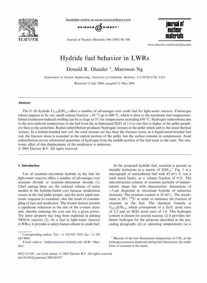
Many of the experiments are of unknown quality andare poorly documented. Neither the Zr/U ratio nor theH/Zr ratio is known for many of the tests. Both in-pilemeasurements of the release-to-birth rate ratio of 85Krand post-irradiation anneal experiments on severalradioactive fission gases are contained in Fig. 2. How-ever, the in-pile experiments only sample release froma �10 lm-thick layer at surface.
In the post-irradiation anneal experiments, the an-neal temperature is given but the irradiation temperatureand the annealing time are not. The �fraction release� isnot defined. Because of the two-phase microstructureof the fuel, the Booth model is not applicable; some ofthe fission fragments from the U phase are stopped inthe ZrHx matrix. Gas bubbles were not reported andno modeling was attempted.
Despite the shortcomings of the experiments citedabove, all agree that gas release up to �600 �C is solelyby recoil. Even at fuel temperatures of 800 �C in the
Fig. 2. Summary of numerous fission gas release measurementsduring or following reactor irradiation (in the postirradiationanneal tests, the abscissa is the anneal temperature); thehorizontal dashed line is the calculated recoil release fractionfor the 12 mm diameter fuel pellet (from Refs. [2,7,9]).
Power TRIGA [4], the fission-gas release fraction ismuch lower than that for oxide fuels at their maximumtemperature of �1500 �C.
The results of the 920-day irradiation of 3.8 cm –diameter TRIGA fuel in the ORR supports the earlierfindings of low fission-gas release [7]. In these tests,U0.31ZrH1.6 with a 235U enrichment of 20% was irradi-ated at a rod-average linear heat rating (LHR) of980 W/cm to a burnup of 65% of the initial 235U (or125 MW d/kg U.2) There was no detectable pressure riseinside the fuel rod. The reported fission-gas release frac-tion of 4 · 10�4 was based on the calculated maximumfuel temperature of 650 �C and a conservative readingof Fig. 2.
Very recent fission-gas release measurements on hy-dride fuel were conducted at the Argonne National Lab-oratory as part of the Department of Energy�s programof conversion of TRIGA fuel from high enrichment ura-nium to fuel with 20% 235U [8]. This last set of results isnot included in Fig. 2 because the release tests were con-ducted in a short-time temperature ramp.
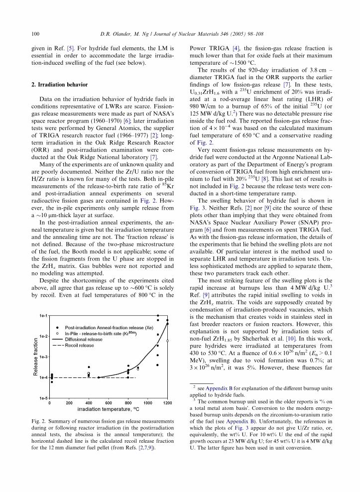
The swelling behavior of hydride fuel is shown inFig. 3. Neither Refs. [2] nor [9] cite the source of theseplots other than implying that they were obtained fromNASA�s Space Nuclear Auxiliary Power (SNAP) pro-gram [6] and from measurements on spent TRIGA fuel.As with the fission-gas release information, the details ofthe experiments that lie behind the swelling plots are notavailable. Of particular interest is the method used toseparate LHR and temperature in irradiation tests. Un-less sophisticated methods are applied to separate them,these two parameters track each other.
The most striking feature of the swelling plots is therapid increase at burnups less than 4 MW d/kg U.3
Ref. [9] attributes the rapid initial swelling to voids inthe ZrHx matrix. The voids are supposedly created bycondensation of irradiation-produced vacancies, whichis the mechanism that creates voids in stainless steel infast breeder reactors or fusion reactors. However, thisexplanation is not supported by irradiation tests ofnon-fuel ZrH1.85 by Shcherbak et al. [10]. In this work,pure hydrides were irradiated at temperatures from430 to 530 �C. At a fluence of 0.6 · 1026 n/m2 (En > 0.1MeV), swelling due to void formation was 0.7%; at3 · 1026 n/m2, it was 5%. However, these fluences far
2 see Appendix B for explanation of the different burnup unitsapplied to hydride fuels.
3 The common burnup unit used in the older reports is �% ona total metal atom basis�. Conversion to the modern energy-based burnup units depends on the zirconium-to-uranium ratioof the fuel (see Appendix B). Unfortunately, the references inwhich the plots of Fig. 3 appear do not give U/Zr ratio, or,equivalently, the wt% U. For 10 wt% U the end of the rapidgrowth occurs at 23 MW d/kg U; for 45 wt% U it is 4 MW d/kgU. The latter figure has been used in unit conversion.
Fig. 3. Swelling of hydride fuel as a function of burnup, temperature and LHR (from Refs. [2,9]).
D.R. Olander, M. Ng / Journal of Nuclear Materials 346 (2005) 98–108 101
exceed the thermal-neutron fluence corresponding to the4 MW d/kg U burnup below which the anomalousswelling is seen in Fig. 3; the 920-day irradiation of fuelwith 45 wt% U to a burnup of 4 MW d/kg U is equiva-lent to a fractional consumption of the 235U of 0.021(from Appendix B). This quantity is also equal to1� expð�rfiss
25 utÞ, where rfiss25 � 500 barns is the fission
cross-section of 235U and ut is the thermal-neutron flu-ence. Thus the end of the rapid swelling period occursat a thermal-neutron fluence of 4 · 1023 n/m2. If the fastfluence in the ORR is of this magnitude, the fluence thatcreates 0.7 vol.% voids in pure hydride [10] is two ordersof magnitude greater than that in the hydride fuel usedin the irradiations at Oak Ridge [7]. The mechanism ofthe anomalous early swelling in hydride fuel, if it is in-deed real, remains unknown.
Whatever the cause, the abnormal swelling behaviorappears only at temperatures above 650 �C. This maybe a significant design restraint: either the temperatureis kept well below the critical value or a large initialfuel-cladding gap is needed.
3. Temperature distribution the in the fuel
Available experimental evidence shows no tempera-ture dependence of the thermal conductivity of ZrHx,which is 5–6 times larger than that of UO2 [11]. Theroom-temperature thermal conductivity varies slightlywith the H/Zr ratio, decreasing from 0.18 W/cm K inZrH1.5 to 0.16 W/cm K in ZrH1.7 [11]. However, thescatter of these data is large enough to warrant the con-clusion that the thermal conductivity is independent ofH/Zr. In addition, a single-line comment in Ref. [2]claims that the thermal conductivity is also independentof uranium content.
For constant thermal conductivity, the temperaturedistribution as a function of radius r is determined bythe expression:
T ðrÞ � T s
T 0 � T s
¼ 1� rR
� �2
; ð1Þ
r = radial position in the pellet; R = fuel radius;Ts = fuel surface temperature; T0 = fuel centerlinetemperature.
The simple parabolic temperature distribution ne-glects the effect of burnup on the thermal conductivity.For the present analysis, the fuel centerline and surfacetemperatures are given in Table 1.
4. Hydrogen redistribution
The properties of the hydride fuel should depend onthe presence of 21 vol.% uranium in the ZrHx matrix.Some undoubtedly do, but other properties, such asthe thermal conductivity, appear to be unaffected bythe presence of metallic uranium. Since the uraniumphase contains no hydrogen,1 all redistribution analyses,including the present one, consider the fuel as pureZrH1.6 [12,13].
Redistribution of hydrogen in metal hydrides is anal-ogous to oxygen redistribution in the mixed-oxide fuelof fast-breeder reactors. In both cases, the moving spe-cies (H or O2�) migrates to the cold periphery of the fuelpellet. In the case of H in ZrHx, the DT from the center-line to the periphery of the fuel (�170 �C) is low com-pared to that in oxide fuel (�800 �C); however, theproperty responsible for redistribution in a temperaturegradient is thermal diffusion. This property, in the formof the heat of transport is substantial for H in ZrHx andthe large ordinary diffusion coefficient of H in thehydride insures that the steady-state distribution isattained quickly.
As long as hydrogen remains in the fuel, there are noneutronic consequences of redistributing hydrogen radi-ally (axial redistribution is a different story; see later).However, increasing the H/Zr ratio at surfaces exposed
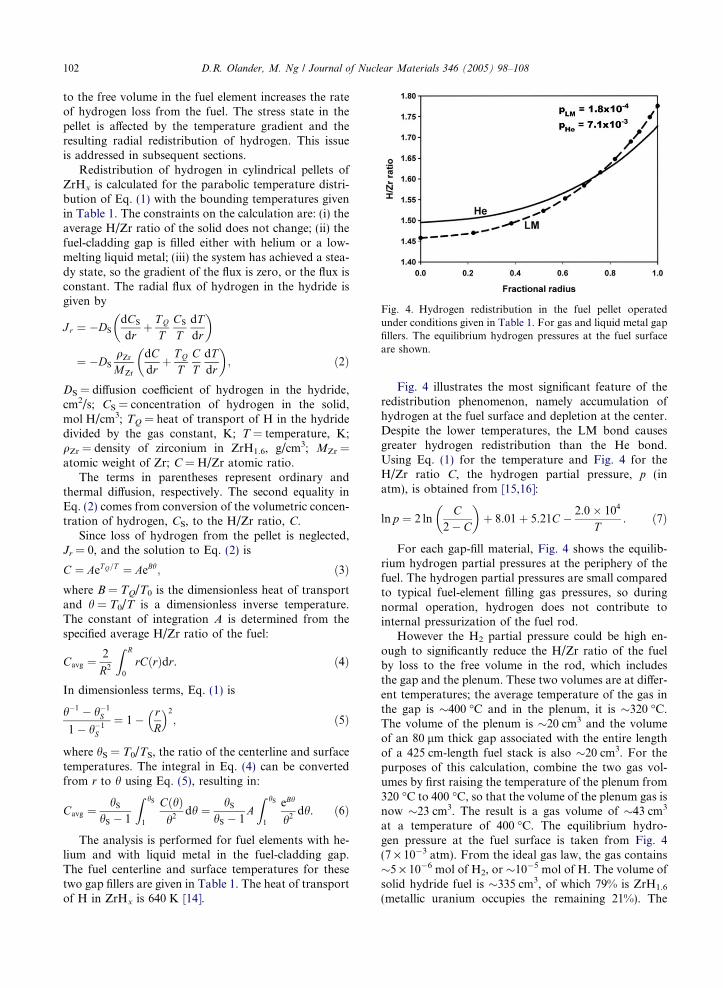
Fig. 4. Hydrogen redistribution in the fuel pellet operatedunder conditions given in Table 1. For gas and liquid metal gapfillers. The equilibrium hydrogen pressures at the fuel surfaceare shown.
102 D.R. Olander, M. Ng / Journal of Nuclear Materials 346 (2005) 98–108
to the free volume in the fuel element increases the rateof hydrogen loss from the fuel. The stress state in thepellet is affected by the temperature gradient and theresulting radial redistribution of hydrogen. This issueis addressed in subsequent sections.
Redistribution of hydrogen in cylindrical pellets ofZrHx is calculated for the parabolic temperature distri-bution of Eq. (1) with the bounding temperatures givenin Table 1. The constraints on the calculation are: (i) theaverage H/Zr ratio of the solid does not change; (ii) thefuel-cladding gap is filled either with helium or a low-melting liquid metal; (iii) the system has achieved a stea-dy state, so the gradient of the flux is zero, or the flux isconstant. The radial flux of hydrogen in the hydride isgiven by
Jr ¼ �DSdCS
drþ T Q
TCS
TdTdr
� �
¼ �DS
qZr
MZr
dCdr
þ T Q
TCT
dTdr
� �; ð2Þ
DS = diffusion coefficient of hydrogen in the hydride,cm2/s; CS = concentration of hydrogen in the solid,mol H/cm3; TQ = heat of transport of H in the hydridedivided by the gas constant, K; T = temperature, K;qZr = density of zirconium in ZrH1.6, g/cm3; MZr =atomic weight of Zr; C = H/Zr atomic ratio.
The terms in parentheses represent ordinary andthermal diffusion, respectively. The second equality inEq. (2) comes from conversion of the volumetric concen-tration of hydrogen, CS, to the H/Zr ratio, C.
Since loss of hydrogen from the pellet is neglected,Jr = 0, and the solution to Eq. (2) is
C ¼ AeTQ=T ¼ AeBh; ð3Þwhere B = TQ/T0 is the dimensionless heat of transportand h = T0/T is a dimensionless inverse temperature.The constant of integration A is determined from thespecified average H/Zr ratio of the fuel:
Cavg ¼2
R2
Z R
0
rCðrÞdr. ð4Þ
In dimensionless terms, Eq. (1) is
h�1 � h�1S
1� h�1S
¼ 1� rR
� �2
; ð5Þ
where hS = T0/TS, the ratio of the centerline and surfacetemperatures. The integral in Eq. (4) can be convertedfrom r to h using Eq. (5), resulting in:
Cavg ¼hS
hS � 1
Z hS
1
CðhÞh2
dh ¼ hS
hS � 1AZ hS
1
eBh
h2dh. ð6Þ
The analysis is performed for fuel elements with he-lium and with liquid metal in the fuel-cladding gap.The fuel centerline and surface temperatures for thesetwo gap fillers are given in Table 1. The heat of transportof H in ZrHx is 640 K [14].
Fig. 4 illustrates the most significant feature of theredistribution phenomenon, namely accumulation ofhydrogen at the fuel surface and depletion at the center.Despite the lower temperatures, the LM bond causesgreater hydrogen redistribution than the He bond.Using Eq. (1) for the temperature and Fig. 4 for theH/Zr ratio C, the hydrogen partial pressure, p (inatm), is obtained from [15,16]:
ln p ¼ 2 lnC
2� C
� �þ 8.01þ 5.21C � 2.0� 104
T. ð7Þ
For each gap-fill material, Fig. 4 shows the equilib-rium hydrogen partial pressures at the periphery of thefuel. The hydrogen partial pressures are small comparedto typical fuel-element filling gas pressures, so duringnormal operation, hydrogen does not contribute tointernal pressurization of the fuel rod.
However the H2 partial pressure could be high en-ough to significantly reduce the H/Zr ratio of the fuelby loss to the free volume in the rod, which includesthe gap and the plenum. These two volumes are at differ-ent temperatures; the average temperature of the gas inthe gap is �400 �C and in the plenum, it is �320 �C.The volume of the plenum is �20 cm3 and the volumeof an 80 lm thick gap associated with the entire lengthof a 425 cm-length fuel stack is also �20 cm3. For thepurposes of this calculation, combine the two gas vol-umes by first raising the temperature of the plenum from320 �C to 400 �C, so that the volume of the plenum gas isnow �23 cm3. The result is a gas volume of �43 cm3
at a temperature of 400 �C. The equilibrium hydro-gen pressure at the fuel surface is taken from Fig. 4(7 · 10�3 atm). From the ideal gas law, the gas contains�5 · 10�6 mol of H2, or �10�5 mol of H. The volume ofsolid hydride fuel is �335 cm3, of which 79% is ZrH1.6
(metallic uranium occupies the remaining 21%). The
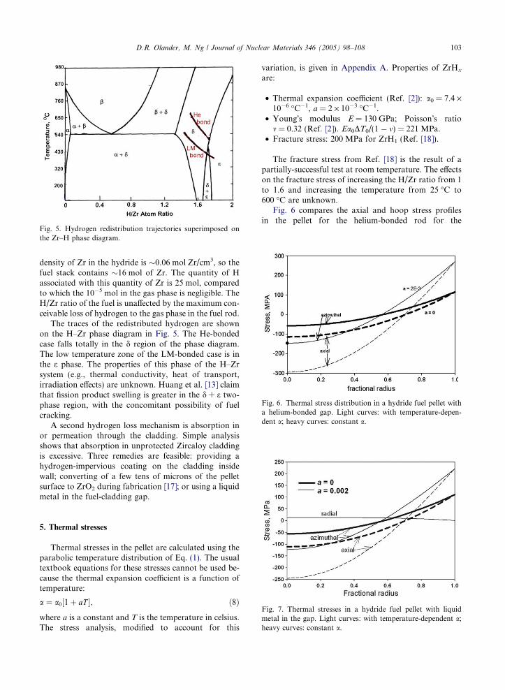
Fig. 5. Hydrogen redistribution trajectories superimposed onthe Zr–H phase diagram.
Fig. 6. Thermal stress distribution in a hydride fuel pellet witha helium-bonded gap. Light curves: with temperature-depen-dent a; heavy curves: constant a.
D.R. Olander, M. Ng / Journal of Nuclear Materials 346 (2005) 98–108 103
density of Zr in the hydride is �0.06 mol Zr/cm3, so thefuel stack contains �16 mol of Zr. The quantity of Hassociated with this quantity of Zr is 25 mol, comparedto which the 10�5 mol in the gas phase is negligible. TheH/Zr ratio of the fuel is unaffected by the maximum con-ceivable loss of hydrogen to the gas phase in the fuel rod.
The traces of the redistributed hydrogen are shownon the H–Zr phase diagram in Fig. 5. The He-bondedcase falls totally in the d region of the phase diagram.The low temperature zone of the LM-bonded case is inthe e phase. The properties of this phase of the H–Zrsystem (e.g., thermal conductivity, heat of transport,irradiation effects) are unknown. Huang et al. [13] claimthat fission product swelling is greater in the d + e two-phase region, with the concomitant possibility of fuelcracking.
A second hydrogen loss mechanism is absorption inor permeation through the cladding. Simple analysisshows that absorption in unprotected Zircaloy claddingis excessive. Three remedies are feasible: providing ahydrogen-impervious coating on the cladding insidewall; converting of a few tens of microns of the pelletsurface to ZrO2 during fabrication [17]; or using a liquidmetal in the fuel-cladding gap.
Fig. 7. Thermal stresses in a hydride fuel pellet with liquidmetal in the gap. Light curves: with temperature-dependent a;heavy curves: constant a.
5. Thermal stresses
Thermal stresses in the pellet are calculated using theparabolic temperature distribution of Eq. (1). The usualtextbook equations for these stresses cannot be used be-cause the thermal expansion coefficient is a function oftemperature:
a ¼ a0½1þ aT ; ð8Þ
where a is a constant and T is the temperature in celsius.The stress analysis, modified to account for this
variation, is given in Appendix A. Properties of ZrHx
are:
• Thermal expansion coefficient (Ref. [2]): a0 = 7.4 ·10�6 �C�1, a = 2 · 10�3 �C�1.
• Young�s modulus E = 130 GPa; Poisson�s ratiom = 0.32 (Ref. [2]). Ea0DT0/(1 � m) = 221 MPa.
• Fracture stress: 200 MPa for ZrH1 (Ref. [18]).
The fracture stress from Ref. [18] is the result of apartially-successful test at room temperature. The effectson the fracture stress of increasing the H/Zr ratio from 1to 1.6 and increasing the temperature from 25 �C to600 �C are unknown.
Fig. 6 compares the axial and hoop stress profilesin the pellet for the helium-bonded rod for the
104 D.R. Olander, M. Ng / Journal of Nuclear Materials 346 (2005) 98–108
conventional constant – a case and for the present casewherein the parameter a is not zero. The latter signifi-cantly enhances the stress variations with r/R.
With a liquid metal in the gap, the only change is uni-form reduction of the fuel temperature by 125 �C. Fig. 7shows the thermal stress distribution for this case. Thestresses are slightly lower than the He-bonded case inFig. 6, but the effect of the temperature-dependent a isthe same.
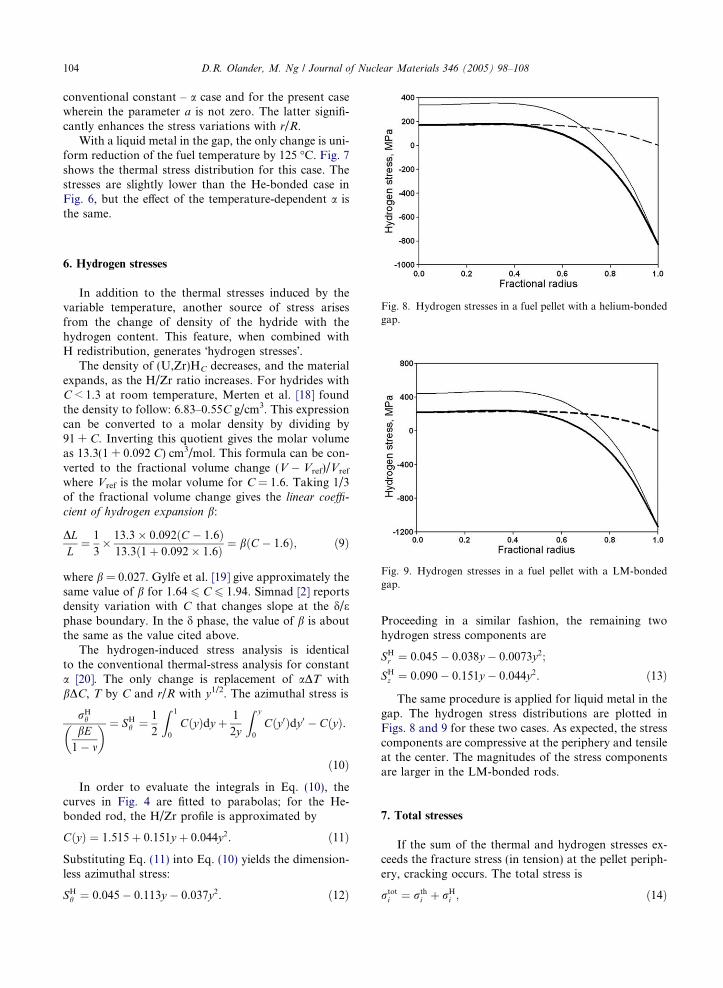
Fig. 8. Hydrogen stresses in a fuel pellet with a helium-bondedgap.
Fig. 9. Hydrogen stresses in a fuel pellet with a LM-bondedgap.
6. Hydrogen stresses
In addition to the thermal stresses induced by thevariable temperature, another source of stress arisesfrom the change of density of the hydride with thehydrogen content. This feature, when combined withH redistribution, generates �hydrogen stresses�.
The density of (U,Zr)HC decreases, and the materialexpands, as the H/Zr ratio increases. For hydrides withC < 1.3 at room temperature, Merten et al. [18] foundthe density to follow: 6.83–0.55C g/cm3. This expressioncan be converted to a molar density by dividing by91 + C. Inverting this quotient gives the molar volumeas 13.3(1 + 0.092 C) cm3/mol. This formula can be con-verted to the fractional volume change (V � Vref)/Vref
where Vref is the molar volume for C = 1.6. Taking 1/3of the fractional volume change gives the linear coeffi-
cient of hydrogen expansion b:
DLL
¼ 1
3� 13.3� 0.092ðC � 1.6Þ
13.3ð1þ 0.092� 1.6Þ ¼ bðC � 1.6Þ; ð9Þ
where b = 0.027. Gylfe et al. [19] give approximately thesame value of b for 1.64 6 C 6 1.94. Simnad [2] reportsdensity variation with C that changes slope at the d/ephase boundary. In the d phase, the value of b is aboutthe same as the value cited above.
The hydrogen-induced stress analysis is identicalto the conventional thermal-stress analysis for constanta [20]. The only change is replacement of aDT withbDC, T by C and r/R with y1/2. The azimuthal stress is
rHh
bE1� m
� � ¼ SHh ¼ 1
2
Z 1
0
CðyÞdy þ 1
2y
Z y
0
Cðy0Þdy0 � CðyÞ.
ð10Þ
In order to evaluate the integrals in Eq. (10), thecurves in Fig. 4 are fitted to parabolas; for the He-bonded rod, the H/Zr profile is approximated by
CðyÞ ¼ 1.515þ 0.151y þ 0.044y2. ð11Þ
Substituting Eq. (11) into Eq. (10) yields the dimension-less azimuthal stress:
SHh ¼ 0.045� 0.113y � 0.037y2. ð12Þ
Proceeding in a similar fashion, the remaining twohydrogen stress components are
SHr ¼ 0.045� 0.038y � 0.0073y2;
SHz ¼ 0.090� 0.151y � 0.044y2. ð13Þ
The same procedure is applied for liquid metal in thegap. The hydrogen stress distributions are plotted inFigs. 8 and 9 for these two cases. As expected, the stresscomponents are compressive at the periphery and tensileat the center. The magnitudes of the stress componentsare larger in the LM-bonded rods.
7. Total stresses
If the sum of the thermal and hydrogen stresses ex-ceeds the fracture stress (in tension) at the pellet periph-ery, cracking occurs. The total stress is
rtoti ¼ rth
i þ rHi ; ð14Þ

Fig. 10. Sum of thermal and hydrogen stresses in a He-bondedfuel rod.
Fig. 11. Sum of thermal and hydrogen stresses in a LM-bondedfuel rod.
D.R. Olander, M. Ng / Journal of Nuclear Materials 346 (2005) 98–108 105
where i is r, h, or z. The radial distributions of the totalstresses are shown in Figs. 10 and 11. In the LM-bondedcase, the nominal fracture stress is exceeded by the axialcomponent of the combined stress over a fractionalradius interval from 0.2 to 0.7.
The maximum tensile stress is 322 MPa at r/R = 0.5.Although the nominal fracture stress is exceeded in theinterior of the pellet, it is unlikely that cracking willoccur because this region is surrounded by zones ofcompressive stress. The azimuthal and axial componentsare larger than the fracture stress at the pellet periphery;however, damage is unlikely because these componentsare compressive.
Fig. 12. Typical axial power distribution in a PWR. The heightof the fuel stack is 3.7 m (Ref. [21]).
8. Axial redistribution
Of greater consequence than radial hydrogen distri-bution in fuel pellets to the neutronic performance of ahydride-fueled reactor is movement of hydrogen axially.The former occurs on the scale of millimeters, and its
neutronic effect, if any, is effectively that of a small-scaleheterogeneity. Axial hydrogen redistribution, on theother hand, displaces large quantities of hydrogen overdistances of meters. Loss of moderating power in thehydrogen-impoverished zone near the fuel-element mid-plane may or may not be adequately compensated bythe higher hydrogen content of the fuel at the top andbottom of the fuel stack.
With the r, z temperature distribution in the fuelspecified, axial hydrogen redistribution is inseparablefrom radial redistribution. Determination of C(r, z) re-quires solution the diffusion equation (including thermaldiffusion) in two spatial dimensions and time. Althoughsteady state is quickly achieved in the radial direction[13], it is not a priori obvious that the axial steady stateis attainable within, say, a reactor cycle. In addition, thediscontinuous nature of the fuel stack could result in arate-limiting kinetic step associated with transfer ofhydrogen via the gas phase in the pellet–pellet interfaces.This is not likely because the overall process is so slowthat gas–solid equilibration at the pellet faces is proba-bly attained. However, the worst case (neutronically) isthe steady state, so this condition is assumed in the fol-lowing analysis. Solution of the two-spatial dimensiondiffusion problem is complicated by the vast differencein the characteristic lengths in the two directions. Thiseffect appears in the non-dimensionalized diffusion equa-tion as the square of the ratio of the pellet radius to thehalf-height of the fuel stack. This ratio is on the order of10�5 and multiplies the axial diffusion term in the con-servation equation.
A simpler, approximate method is as follows:
1. The thermal state is specified by selection of the inletcoolant temperature and the relative axial variationof the linear heat rating, LHR(z)/LHR(0),�L 6 z 6 L, where 2L is the height of the fuel stack.A typical PWR axial power shape is shown in Fig. 12.

Fig. 13. Axial variation of the radially-averaged fuel tem-perature.
Fig. 14. Axial H/Zr profile at steady state.
106 D.R. Olander, M. Ng / Journal of Nuclear Materials 346 (2005) 98–108
For a coolant temperature of 300 �C at the midplane(the value in Table 1), the inlet temperature is 275 �Cand the temperature rise through the core is 50 �C.The fuel surface and centerline temperatures are fixedby hooking the axial solution to the conditions givenin Table 1 (for the He-bonded case) at z = 0.
2. Axial hydrogen redistribution is assumed to be drivenby the radially-averaged fuel temperature as a func-tion of z (Fig. 13).
3. In order to prevent the calculated H/Zr ratio fromexceeding 2.0, the heat of transport (in Kelvins) isforced to approach zero as H/Zr ! 2 according tothe function
1.34ð2� CÞ0.32.
This function has two features: first, it is unity atC ¼ 1.6; second, it approaches zero as C ! 2. The firstcharacteristic recovers the literature value of the heatof transport (TQ = 640 K). The second prevents H/Zrrations greater than 2 from being calculated. With thismodification, the condition of zero hydrogen flux alongthe length of the fuel stack (because no hydrogen escapesfrom the ends) is the z analog of the expression in paren-theses in Eq. (2):
dCdz
¼ �1.34TQð2� CÞ0.32C dT
T2. ð15Þ
Eq. (16) is solved numerically using an initial conditionCð�LÞ that produces the correct overall average H/Zrratio:
1
2L
Z L
�LCðzÞdz ¼ 1.6. ð16Þ
The resulting hydrogen redistribution profile, withCð�LÞ ¼ 1.9999, is shown in Fig. 14. All of the hydro-gen in the region beneath the H/Zr = 1.6 line has beenmoved to the top and bottom of the fuel stack.
Whether the final hydrogen distribution of Fig. 14can be achieved in a typical in-reactor fuel lifetime of6 years can be roughly estimated as follows. In transientdiffusion problems, steady state is �75% attained whenDt/L2 � 2. Taking D � 3 · 10�5 cm2/s and L = 185 cmgives a time of 75 years. However, for the following rea-sons, this estimate should not be accepted until a fulltransient analysis of the problem is performed: (i) theabove estimation method is not valid when thermal dif-fusion accompanies ordinary diffusion; (ii) the strong ra-dial and axial temperature variations make the estimateof D very uncertain; (iii) only one set of thermal condi-tions has been analyzed; although typical of currentLWRs, other conditions may be more conducive tohydrogen movement.
9. Conclusions
Several in-reactor behavior features of theU0.31ZrH1.6 power-reactor fuel have been analyzed andtheir effects on fuel performance assessed.
Fission-gas release appears to be very small, even forirradiations to high burnups. Fission product swelling,on the other hand, shows a very large initial increaseat temperatures exceeding 650 �C. This last feature,rather than hydrogen loss, may fix the maximum fueltemperature.
A process that has no analog in oxide LWR fuel ishydrogen redistribution driven by solid-state thermaldiffusion. This process results in increase of the H/Zrratio at the pellet periphery with concomitant impover-ishment at the fuel centerline.
Under normal operating conditions with He in thegap, loss of H from the fuel by transfer to the gas inthe plenum and the gap is negligible. On the other hand,a transient that pushes fuel temperatures above 1000 �Ccould release significant quantities of hydrogen. The
D.R. Olander, M. Ng / Journal of Nuclear Materials 346 (2005) 98–108 107
kinetics of this desorption process have not been studied,nor has the rate of the subsequent re-absorption step fol-lowing cool-down.
Transients in fuel rods with an LM-bonded gap arealtogether different. Hydrogen loss from accidents shortof cladding burst is impossible. The equilibrium hydro-gen pressure would have to exceed the internal rod totalpressure in order to force H2 gas through the liquidmetal and into the plenum. The temperatures requiredto generate the necessary tens of atm of H2 are well over1500 �C.
Accumulation of hydrogen at the fuel surface willdamage unprotected Zircaloy cladding. Several remediesfor this problem, short of switching to a stainless steel ora high-nickel alloy cladding, are available.
Stresses in the operating hydride fuel pellet arise fromtwo sources: thermal stress (with a variable coefficient ofthermal expansion) and stresses developed by the combi-nation of hydrogen redistribution and the variation offuel density with H/Zr ratio. These components act inopposing directions: thermal stresses are compressivenear the center and tensile at the periphery; hydrogenstresses are tensile near the centerline and compressiveat the surface. The total stress is the sum of these twocomponents. With helium in the fuel-cladding gap, allthree stress components are less than the fracture stress(which, however, is poorly known). With the gap filledwith a liquid metal, the tensile axial component exceedsthe nominal fracture stress over the interval 0.2 <r/R < 0.7. This confined stress state will probably notcause pellet cracking.
Axial redistribution of hydrogen is significant, andpotentially could affect the neutronics of the hydride-fueled reactor. However, the time to achieve the finalsteady-state distribution may be much longer than in-reactor fuel lifetimes. A full transient analysis is neededto settle this matter.
Finally, the effects of the separate uranium metalphase, which occupies a volume fraction of 0.21 in thefuel, on the mechanical and thermal properties areunknown.
Appendix A. Thermal stresses with variable coefficient
of thermal expansion
The generalized Hooke�s law in cylindrical coordi-nates, including thermal expansion, is
er ¼1
E½rr � mðrh þ rzÞ þ aDT ; ðA:1Þ
eh ¼1
E½rh � mðrr þ rzÞ þ aDT ; ðA:2Þ
ez ¼1
E½rz � mðrr þ rhÞ þ aDT ; ðA:3Þ
where E is Young�s modulus, m is Poisson�s ratio and a isthe linear coefficient of thermal expansion, which isassumed to be a linear function of temperature but inde-pendent of the H/Zr ratio. DT is the numerator of Eq.(1). Plane strain is assumed, so that ez is a constant.The relation between the strain components is
deh
drþ eh � er
r¼ 0. ðA:4Þ
Substituting Eqs. (A.1) and (A.2) into Eq. (A.4) yields:
d
dr½rh � mðrr þ rzÞ þ E
d
drðaDT Þ þ 1þ m
rðrh � rrÞ ¼ 0.
ðA:5Þ
Taking the derivative of Eq. (A.3) and substituting drz/dr into Eq. (A.5) yields, after the usual manipulation,
1
r3d
drr3
drr
dr
� �¼ � E
1� m1
rd
draDTð Þ; ðA:6Þ
which differs from the standard starting equation in thatthe coefficient of thermal expansion cannot be removedfrom the derivative.
The dimensionless temperature difference is definedby
DT=DT 0 ¼ 1� g2; ðA:7Þ
where DT0 = T0 � TS and g = r/R.Inserting Eq. (8) for a into Eq. (A.6) yields:
d
dgg3 dS
thr
dg
� �¼ �g2 d
dg½Aþ Bð1� g2Þð1� g2Þ
� �;
ðA:8Þ
where Sthr is the dimensionless form of the radial thermal
stress:
Sthr ¼ rr
Ea0DT 0
1� m
� � ðA:9Þ
and
A ¼ 1þ aT S; B ¼ aDT 0. ðA:10Þ
The boundary conditions are
dSthr =dg ¼ 0 at g ¼ 0 and Sth
r ¼ 0 at g ¼ 1.
ðA:11Þ
Integrating Eq (A.8) twice results in:
Sthr ¼ � 1
4ðAþ 2BÞð1� g2Þ þ 1
6Bð1� g4Þ. ðA:12Þ
For a constant thermal expansion coefficient, a = 0,A = 1 and B = 0 and Eq. (A.12) reduces to Sth
r ¼�1=4ð1� g2Þ, which is the standard solution for thethermal stress caused by a parabolic temperature distri-bution in a solid cylindrical pellet. The equilibriumcondition,

108 D.R. Olander, M. Ng / Journal of Nuclear Materials 346 (2005) 98–108
o
orðrrrÞ � rh ¼ 0 ðA:13Þ
is used to determine the hoop stress:
Sthh ¼ � 1
4ðAþ 2BÞð1� 3g2Þ þ 1
6Bð1� 5g4Þ. ðA:14Þ
The axial stress is calculated as follows [22]: First theaxial stress distribution with the pellet completelyrestrained axially (ez = 0) is determined. Next, the radialaverage of this stress is calculated. The restraint is thenremoved, so the desired axial stress is rz ¼ rR
z � rRz ,
where the superscript R indicates the restrained condi-tion. The result is
Sthz ¼ � 1
2ð1� 2g2ÞA� 2
31� 3g2 þ 3
2g4
� �B. ðA:15Þ
Appendix B. Burnup units for U–Zr hydride fuels
The burnup expressed as a fraction of initial metalatoms (U + Zr) consumed, or FIMA, is defined by
FIMA ¼ DN 25=ðNU þ NZrÞ; ðB:1Þ
where DN25 represents the moles of 235U consumed byfission, NU is the initial total moles of uranium, andNZr is the moles of zirconium. Dividing by NU, the burn-up can be expressed as the �fraction of initial uraniumatoms� consumed:
DN 25=NU ¼ ð1þ NZr=NUÞ � FIMA. ðB:2Þ
In conventional burnup units:
BU ðMWd=kg UÞ¼ 950ðDN 25=NUÞ¼ 950ð1þNZr=NUÞ�FIMA. ðB:3Þ
Another measure of burnup of hydride fuels is �fractionof initial U-235 consumed�. This is given by
DN 25
N 025
¼ NU
N 025
� DN 25
NU
¼ FIMA
q� 1þ NZr
NU
� �; ðB:4Þ
where q is the uranium enrichment.All conversions require knowledge of the zirconium-
to-uranium atom ratio. The literature usually expressesthe total uranium content of hydride fuel in terms ofweight percent (based on metals only). Thus, fuel with10 wt% uranium is equivalent to NZr/NU = 24, and45 wt% converts to NZr/NU = 3.2.
References
[1] E. Greenspan, H. Garkisch, J. Malen, M. Moalem, D.Olander, B. Petrovic, Z. Shayer, N. Todreas, Trans. Am.Nucl. Soc. 89 (2003) 381.
[2] M.T. Simnad, Nucl. Eng. Des. 64 (1981) 403.[3] R. Chesworth, G. West, Final Results of Qualification
Testing of TRIGA Fuel in the Oak Ridge ResearchReactor (ORR), Paper Presented at the InternationalMeeting on Reduced Enrichment for Research and TestReactors, Petten, Netherlands, 1985.
[4] C. Toma et al., Characterization of TRIGA LEU FuelBehavior in 14 MW Core, un-numbered report, Institutefor Nuclear Research, Pitesti, Romania.
[5] D. Wongsawaeng, D. Olander, Liquid-Metal Bonding ofthe Fuel-Cladding Gap in Light-Water Reactors, Interna-tional Meeting on Light-Water Reactor Fuel Performance,Orlando, FL, 2004.
[6] A.F. Lillie et al., USAEC Report AI-AEC-13084, AtomicsInternational, 1973.
[7] G. West, M. Simnad, G. Copeland, Final Results fromTRIGA LEU Fuel Postirradiation Examination andEvaluation Following Long-Term Irradiation Testing inthe ORR, General Atomics report GA-A18641, 1986.
[8] Yeon Soo Kim, G. Hofmann, Nucl. Technol., submittedfor publication.
[9] GA Technologies, Inc. Uranium–Zirconium HydrideTRIGA LEU Fuel, Appendix I-7, Research Reactor CoreConversion Guidebook, IAEA-TEDOC-643 (dateunknown).
[10] V.I. Shcherbak et al., Atomnaya Energiya 31 (1991) 178.[11] S. Yamanaka et al., J. Nucl. Mater. 294 (2001) 94.[12] U. Merten et al., J. Nucl. Mater. 10 (1963) 201.[13] J. Huang et al., J. Nucl. Sci. Technol. 37 (2000) 887.[14] A. Sommer, W. Dennison, NAA Report NAA-SR-5066,
1960.[15] Wei-E. Wang, D.R. Olander, J. Am. Ceram. Soc. 78 (1995)
3323.[16] L. Libowitz, J. Nucl. Mater. 5 (1962) 228.[17] G. Eggers, Method of Making ZrH Fuel Element, US
Patent 4,071,587, column 2, 1978.[18] U. Merten et al., in: The Proceedings of the Second
Conference On Peaceful Uses of Atomic Energy, P/789,Geneva, 1958.
[19] J.D. Gylfe et al., Evaluation of Zirconium Hydride asModerator in Integral Boiling-Water Superheat Reactors,NAA-SR-5943, 1960, p. 11.
[20] C.F. Bonilla, Nuclear Engineering, McGraw-Hill, 1957,566 p.
[21] R. Montgomery, R. Yang, Topical Report on Reactivity-Initiated Accidents: Bases for RIA Fuel and Core Coola-bility Criteria, Figs. 3–12, EPRI 1002865, 2002.
[22] H. Rust, Nucl. Power Plant Eng. (1979) 395.