Improved Navy Ship Fuel Systems
14
Improved Navy Ship Fuel Systems ABSTRACT The forward deployment of a naval task force is dependent upon the performance of the Underway Replemshment (UNREP) systems, espe- cially Fueling At Sea (FAS). A series of office of Naval Research (ONR) spon- sored developments are reviewed that will help Navy ships to achieve current and future FAS requirements with reduced manning, Life Cycle Cost (LCC), and risk of pollution. The follow- ing developments are presented I DDG 51 class Improved Fuel Fill Control System (IFFCS) development and DDG 57 at sea demonstration. Combat Logistic Force (CLF) Fuel ’Ikansfer Recording System and the AOE 8 installation and operating expe- rience. CV/CVN Fuel Tank Monitoring and Display System development. I Improved UNREP Phone, Distance, and Data Link System development. I Tensioned Hose Fueling At Sea System (THFASS) Development. Improvements of the Navy’s fuel systems are necessary to help meet current and future operational, LCC, manning, and environmental require- ments . The improvements provided by these developments illustrate that COTS techndogies and hardware can have a significant impact on the Fleet’s FAS and storage systems. INTRODUCTION he capability of a naval task force to remain forward deployed de- pends on the performance of the Underway Replenishment (UN- REP) systems, especially Fueling At Sea (FAS). Over the last 10 years, a series of Office of Naval Research (ONR) sponsored FAS hardware and control systems were developed. These systems will enhance the capability of the Navy’s ships to achieve sigmficant improvements in pol- lution avoidance and FAS operational capability with reduced manning and Life Cycle Costs. The Navy is pursuing a program of research, policy, ship and equipment design, and operational procedures to reduce the risk of fuel oil pol- lution to a minimum. BACKGROUND Ship fuel storage systems on many surface combatants, such as the DD 963, CG 47, and DDG 51 Class ships, are seawater-compensated where seawater, fuel, or a combination of each maintain the tanks in a “full” condition at all times. The advantage of the compensated fuel storage system is that it maintains intact stability by overcoming the negative effect of free surface and the rise in the center of gravity However, it is more prone to the discharge of contaminated seawater ballast or the accidental discharge of fuel during refueling. Combat Logistics Force (CLF) ships (AOE, AO, T-AO) that supply fuel to combatants and aircraft carriers (CV; CVN) have a common problem of account- ing for fuel transferred and determining the amount of fuel stored in their tanks. Manual tank soundings are the primary source of fuel tank status information and Tank Level Indicators (TLI) are secondw. Historically, TLIs have been a continuing maintenance item, and readings are subject to interpretation. Manual tank soundmgs are labor intensive and time consuming, and can require four persons up to four hours to complete the tank soundings on an aircraft carrier. The objective of the ONR sponsored effort was to develop improved ship fuel transfer and fill systems that would provide warfighting payoffs of reduced along- side times, more accurate fuel accounting, and more complete tank fillings during FAS operations, while reducing the risk of system overpressure or the overboard discharge of fuel. The technical approach was to employ state-of-the-art control systems and sensors capable of meeting the requirements in a naval ship environment. The benefits of the improved systems are: (1) reduced ship vulnerability to collision or enemy attack through reduced alongside times, (2) increased availability of both combatant and CLF ships because of reduced time to conduct FAS oper- ations, (3) reduced risk of pollution and increased ability to meet environmental restrictions, (4) reduced manning requirements, and (5) reduced Life Cycle Costs (LCC) by using Commercial-Off-The-Shelf (COTS) hardware. NAVY SHIP FUEL FILL AND STORAGE SYSTEMS Except for the accidental overboard discharge of fuel, the non-compensated fuel storage systems pose minimal risk of pollution. Unless intentionally ballasted, a NAVAL ENGINEERS JOURNAL May 1999 71
-
Upload
independent -
Category
Documents
-
view
1 -
download
0
Transcript of Improved Navy Ship Fuel Systems

Improved Navy Ship Fuel Systems
ABSTRACT The forward deployment of a naval task force is dependent upon the performance of the Underway Replemshment (UNREP) systems, espe- cially Fueling At Sea (FAS). A series of office of Naval Research (ONR) spon- sored developments are reviewed that will help Navy ships to achieve current and future FAS requirements with reduced manning, Life Cycle Cost (LCC), and risk of pollution. The follow- ing developments are presented I DDG 51 class Improved Fuel Fill
Control System (IFFCS) development and DDG 57 at sea demonstration. Combat Logistic Force (CLF) Fuel ’Ikansfer Recording System and the AOE 8 installation and operating expe- rience. CV/CVN Fuel Tank Monitoring and Display System development.
I Improved UNREP Phone, Distance, and Data Link System development. I Tensioned Hose Fueling At Sea
System (THFASS) Development. Improvements of the Navy’s fuel
systems are necessary to help meet current and future operational, LCC, manning, and environmental require- ments. The improvements provided by these developments illustrate that COTS techndogies and hardware can have a significant impact on the Fleet’s FAS and storage systems.
INTRODUCTION
he capability of a naval task force to remain forward deployed de- pends on the performance of the Underway Replenishment (UN- REP) systems, especially Fueling At Sea (FAS). Over the last 10 years, a series of Office of Naval Research (ONR) sponsored FAS
hardware and control systems were developed. These systems will enhance the capability of the Navy’s ships to achieve sigmficant improvements in pol- lution avoidance and FAS operational capability with reduced manning and Life Cycle Costs. The Navy is pursuing a program of research, policy, ship and equipment design, and operational procedures to reduce the risk of fuel oil pol- lution to a minimum.
BACKGROUND Ship fuel storage systems on many surface combatants, such as the DD 963, CG 47, and DDG 51 Class ships, are seawater-compensated where seawater, fuel, or a combination of each maintain the tanks in a “full” condition at all times. The advantage of the compensated fuel storage system is that it maintains intact stability by overcoming the negative effect of free surface and the rise in the center of gravity However, it is more prone to the discharge of contaminated seawater ballast or the accidental discharge of fuel during refueling.
Combat Logistics Force (CLF) ships (AOE, AO, T-AO) that supply fuel to combatants and aircraft carriers (CV; CVN) have a common problem of account- ing for fuel transferred and determining the amount of fuel stored in their tanks. Manual tank soundings are the primary source of fuel tank status information and Tank Level Indicators (TLI) are secondw. Historically, TLIs have been a continuing maintenance item, and readings are subject to interpretation. Manual tank soundmgs are labor intensive and time consuming, and can require four persons up to four hours to complete the tank soundings on an aircraft carrier.
The objective of the ONR sponsored effort was to develop improved ship fuel transfer and fill systems that would provide warfighting payoffs of reduced along- side times, more accurate fuel accounting, and more complete tank fillings during FAS operations, while reducing the risk of system overpressure or the overboard discharge of fuel.
The technical approach was to employ state-of-the-art control systems and sensors capable of meeting the requirements in a naval ship environment. The benefits of the improved systems are: (1) reduced ship vulnerability to collision or enemy attack through reduced alongside times, (2) increased availability of both combatant and CLF ships because of reduced time to conduct FAS oper- ations, (3) reduced risk of pollution and increased ability to meet environmental restrictions, (4) reduced manning requirements, and (5) reduced Life Cycle Costs (LCC) by using Commercial-Off-The-Shelf (COTS) hardware.
NAVY SHIP FUEL FILL AND STORAGE SYSTEMS Except for the accidental overboard discharge of fuel, the non-compensated fuel storage systems pose minimal risk of pollution. Unless intentionally ballasted, a
NAVAL ENGINEERS JOURNAL May 1999 71
Improved Navy Ship Fuel Systems
non-compensated fuel storage system has only fuel in the storage tanks. However, on smaller combatants, compen- sated fuel storage systems are more desirable than non- compensated systems for ship stability reasons.
DD 963, CG 47 and DDG 51 Class ships employ a seawater-compensated storage system where the tanks are always filled with seawater, fuel, or a combination. When fueling, water is discharged overboard until the tanks are almost filled with fuel. The ship’s hull, frames, and innerbottom form the fuel storage tank structure. A two-tank group configuration in which four to six individual tanks are connected to form a tank group is shown in Figure 1. A schematic of the six tank groups for a DDG 51 Class ship is also illustrated in Figure 2. The tank groups are designed for a fill rate of 1000 gallons per minute (gpm) per tank group. This ship class can receive fuel from an oiler through one or two hoses with a delivery rate of 3000 gpm per hose into the six tank groups.
The fuel fill operation is controlled by the “Oil King” under the responsibility of the Chief Engineer on the re- ceiving ship. After the receiving ship comes alongside the oiler and the FAS rigging has been established, the re- ceiving ship instructs the oiler when to start pumping and the pumping pressure to use. Initially, pressure is at a minimum to ensure that the piping ahgnment is correct; then, pressure is increased to its maximum. As the tank groups are filled and taken off-line, the pressure is de- creased until the receiving ship is topped off and the oiler
is instructed to stop pumping. The fuel hoses are drained either by the oiler taking a back suction or the receiving ship performing a “blow down” using air pressure.
The Oil King operates the fuel fill system with mfr- mation provided by TLIs installed in each tank, pressure at the FAS receiving station($, and, on some ships, the tank top pressure. Figure 3 illustrates the fuel fill and transfer control console on a DD 963 or CG 47 class ship. Figure 4 illustrates the fuel fill and transfer panel on a DDG 51 class ship, the USS Mitscher (DDG 57). During numerous ship visits, it was found that different ships, even within the same class, operate the fuel fill system with variances from the standard Engineering Operation Sequencing System (EOSS). This is understandable due to ship-specific and perhaps temporary conditions, oper- ational need, and probably the greatest factors, training and recent experience. EOSS directs the number of hoses and pumping pressures required, as determined by the number of tank groups to be filled.
During FAS and in port refueling operations, there is always a possibility for overfilling or overpressuring and damaging a tank. These mishaps can be caused by an incorrect tank alignment, a valve not being opened in time or suddenly closing, inaccurate or inoperative TLIs, or excessive pressure at the FAS receiving station. When a tank group control valve closes in response to a high- pressure alarm switch, an unseated fuel probe can result in a fuel spill and personnel being “wetted” with fuel. As
Seawater Compensated Fuel Oil and Transfer System
OXRFLOW CXPWSlCU TANK
F I G U R E 1. Two-Tank Group Configuration
12 May 1999 NAVAL ENGINEERS JOURNAL

Improved Navy Ship Fuel Systems
F I G U R E 2. DDG Sl Class Fuel Fill And Transfer System
F 1 G U R E 3. DD 963KG 47 Fuel Fill And nansfer Control Console
NAVAL ENGINEERS JOURNAL May 1999 13

lmpmved Navy Ship Fuel Sysfems
F I G U R E 4. DDG 57 Fud Fill And Ransfer Control Panel
a minimum, it extends the alongside time to reseat the probe and reinitiate fuehg.
DDG 51 CLASS IMPROVED FUEL FILL SYSTEM DEVELOPMENTS The limitations of seawater-compensated fuel systems were identified in discussions with ship’s personnel, gov- ernment engineers, and support contractors familiar with the system. These limitations include the inability to achieve complete tank fiulng and to positively control ov- erpressure conditions, and the risk of overboard discharge of ody ballast and fuel. Environmental regulations will re- quire fuel system improvements to achieve compliance in the future. Although improvements have been made on the DDG 51 class, the basic limitations are:
A continuing pollution risk exists due to the potential discharge of oily ballast or fuel.
H There is a risk of system overpressure that can damage a tank, unseat fuel probes, and burst fuel hoses result- ing in personnel being sprayed with fuel and fuel being discharged overboard.
H The maximum design fuel receiving rate of 3000 gpm for a single hose, or 6000 gpm for two hoses, has been difficult to attain on a routine basis.
H The seawater-compensated fuel storage tanks are sometimes not filled to capacity and excessive quan- tities of seawater remain in the tanks after fueling.
H The inaccuracy and reliability of TLIs are continuing problems that do not inspire operator confidence.
FUEL TANK FLOW IMPROVEMENTS- DIFFUSERS When the DDG 51 was under construction, NAVSEA ex- pressed a concern that fuel flow paths w i t h the tank groups would be a problem because of some of the tanks being shallow and containing a complex frame structure. Thus, it was no surprise when the lead ship experienced problems of retained seawater after fuehg, the mixing of fuel and water, and even the overboard discharge of fuel. Under some conditions, fuel may actually bypass a tank and proceed to the next tank or overboard, resulting in incomplete tank fhg and pollution.
Originallx the tank inlet consisted of a bell mouth that terminated the piping. The tank outlet is a similar fitting. Under an exploratory development effort sponsored by ONR, the fuel tank inlet and outlet diffuser system shown in Figure 5 was developed to improve flow conditions within the tanks. The payoffs of the diffusers are in- creased fill rates, less seawater and fuel mixing, and more complete tank fhg.
The diffuser system extended the tank inlet to a diffuser pipe extended across the top of the tank, and on the outlet side extended the discharge pipe back into and across the lower tank structure, as shown in the figure. This ap- proach not only slowed the inlet velocity and mixing of the fuel entering the tank, but brought the fuel across the tank top and “pressed down” the seawater being displaced from the tank. On the outlet side, the diffuser reduces mixing and increases the time for the fuel to separate from the water.
Theoretical analysis indicated that the diffuser design would improve the fuel flox As a result, scale models were built that replicated the flow patterns. The tank model and the test results are shown in Figure 5. Model testing showed that the diffuser concept worked very well. This effort transitioned to NAVSEA and diffusers have been backfitted into existing DDG 51 class ships and incorpo- rated in new construction. Figure 6 shows the installation of fuel tank diffusers in the DDG 60.
14 May 1999 NAVAL ENGINEERS JOURNAL

Impmved nary Wp Fnei Sysms
Fuel TanWDiffuser Simulation
F I G U R E 5. DDG 5l Class Fuel lhnk Diffuser Development
IMPROVED FUEL FILL CONTROL SYSTEM (IFFCS) The IFFCS was developed to provide the Oil King with improved visibility and contrd over the fuel fill operation. The IFFCS demonstration system installed on the U S MITSCHER (DDG 57) was designed to operate in p a d e l with the existing fuel fill and transfer panel without im- pacting the existing capability Since it is a demonstration system, the IFFCS can be decoupled from the Fuel Fill and Transfer Panel by pushug a single switch and full as- built control will be immediatety restored. The demon- stration IFFCS has implemented the current EOSS with few changes, which is a very conservative approach. To implement the IFFCS on the DDG 57, the as-built fuel fill system was augmented with the following items:
The Man-Machine Interface (MMI), shown in Figure 7, was installed in the fue1 lab near the fuel fill and transfer panel. The MMI employs an industrial grade computer with an “expert software system.” The expert system, shown in Figure 8, processes information in much the same way that an Oil Kmg would if he had the sensor information and time to analyze the data. The IFFCS uses COTS MMI software that is tailored for the spe- cific ship’s parameters, incorporating information about the fuel storage system, tank capacities, and EOSS procedures.
F I G U R E 6. DDG 60 Fuel lhnk Diffuser Installation
NAVAL EN6lNEERS JOURNAL May 1999

Improved Navy Ship Fuel Systems
F I G U R E 7. IFFCS MadMachhe Interface (MMI)
Under IFFCS, the operator retains full control and can intervene at any time to moddy the actions of the IFFCS, or at his discretion, to return control to the existing fuel fill and transfer panel. The transfer occurs smoothly and the IFFCS continues to function as a much improved MMI. Additionallx the IFFCSMMI provides the operator with system diagnostics, and in the future, embedded training and an interface to ship-wide information systems. A data link between the oiler and receiving ship is a pos- sibility to ensure additional control of the fuehg evolution and reduce the number of personnel needed to perform the FAS evolution. rn Also installed in the fuel lab are Inputloutput (I/O)
interface electronics and a microprocessor used to pro- cess data between the MMI and the existing fuel fill and transfer panel.
rn Clamp-on ultrasonic flowmeters (Figure 9) are used to determine the flow rate into each of the six tank groups and are installed on each tank group overboard dis- charge line.
rn 110 electronics (Figure 9) were installed near each tank group to process signals from the flowmeters, pressure transducers, and valve actuators.
rn A simple modification to the existing tank group control valve actuators (Figure 10) was made to achieve a "con-
Rule-Based Expert System for Error Recognition and Control of the Automated Fuel Fill System Advanced Development Demonstration
DATA FLOW DIAGRAM
F I G U R E 8. IFFCS Expert Software System
16 May 1999 NAVAL ENGINEERS JOURNAL

Improved Navy Ship Fuel Systems
Ultrasonic Flowmeter Installed on Tank Group
Overboard Discharge
Local Tank Group Controller
F I G U R E 9. DDG 57 IFFCS Clamp-On Flowmeters and 110 Electronics Installation
Improved Fuel Fill Control System DDG 57 Installation
F I G U R E 10. DDG 57 IFFCS Tank Group Valve Actuator Modification
NAVAL ENGINEERS JOURNAL May 1999 77

trolled closing,” and to enable the valves to be incre- mentally positioned, stopped, or reversed if required. Prior to ship installation, a mockup of the IFFCS (Fig-
ure 11) was assembled and demonstrated at a shorebased facility using actual IFFCS hardware. During the demon- strations, Fleet operators and representatives of ONR, OPNAY NSWC DD, and NAVSEA operated the mockup and provided recommendations. Fleet personnel com- mented on the realism of the shorebased system. Throughout this effort, an analysis of failure modes was performed, and fail-safe control and risk reduction mea- sures were incorporated in the design and tested. Specif- ic&, single and multiple failures were induced, such as excessive delivery pressure, loss of ship’s pawer, central processor failure, tank group controller failure, and TLU Aowmeter failures. The simulated failures validated the ability of LFFCS to maintain Sate control under extreme conditions. The IFFCS development greatly benefitted from the input and suggestions received from NAVSEA (SEA 03L34 and 03J), the SMART SHIP Project Office, and the DDG 51 class support contractors.
The IFFCS installed on the DDG 57 employed the ex- isting EOSS with minimum changes. However, based on the improved MMI and control provided, and its predictive and preemptive capability, many of the operators recog- nized that the fuehg evolution could be accomplished at even higher fill rates without increasing the risk of over-
pressure, overfill, or pollution. However, to achieve this, a departure from the existjng EOSS wouid be required. Specifically, all the tank groups that are to be fueled couM be brought online sooner and kept there longer. This is a departure from the current EOSS that usually prescribes fewer tank groups online so that they can be better man- aged, providmg more time between tank group closings, and makmg reductions in pumping pressures.
The IFFCS with a modified EOSS would bring a maxi- mum number of tank groups online for the major duration of the refueling. In this wax although ship-to-shlp transfer rates have been increased, fbw rates to the larger number of tank groups would not be increased. Under the modified EOSS the fuel flow into the tank groups w d d be distrib- uted so that the overall flow into the individual tank groups at a given receiving station pressure would actually be lower as more tank groups wodd be open. Further, sudden increased flow rates and tank top pressures in online tank groups due to the closing of a tank group would be mini- mized, and fewer pressure changes would be required from the oiler. Therebre, the IFFCS would allow refueling to be accomphshed with a high degree of control and safety
When observing the operating practices of Oil Kings, it was found that some operators would close an almost filled tank group early when TLI accuracy was suspect due to mixing and foaming. Then, near the end of fuehng when
DDG 51 Class IFFCS Hardware A o i l Lab - IFFCS Operator Console
B - DDG 51 Class Fuel Fill SystedSending Ship Simulator C - Clamp on Ultrasonic Flowmeter (One for each tank group) D - Six Tank Group YO Units
- System Controller and VO
F I G U R E ll. Improved Fuel Fill Contd System Development Wkty
78 May 1999 NAYIL ENGIIEERS JOURlCIt

Improved Navy Ship Fuel Systems
the TLI readmgs had settled, the tank group would be bmught back online to be topped off without risk of overfill. This technque could be easily implemented into the IFFCS but is probably not required because of the ability to re- duce the N1 rate to a minimum when a tank group is nearly filled.
In addition to using information from the TLIs, the IFFCS receives data from flowmeters installed on the overboard discharge line €or each tank group to measure the seawater being displaced as the tank group is filled. The TLI and flawmeter data are compared, and real-time algorithms continuously calculate tank status; predict fu- ture status; trigger wamings and alarms; generate oper- atm prompts; and present confidence factors for the ac- curacy of the TLIs. The TLIs are always used as the primary sensors to control the filling of a tank group; however, if they are determined to be in error, the flow- meters are used to determine the percentage of tank fill. Additionall5 within the IFFCS Expert System there is final check on both the TLI and flawmeter data. The fill rate and N1 time are calculated in real-time based on receiving station pressure and the piping design flow loss data for the specific ship.
The as-built valve actuators either !idly open or close the tank group valves and cannot be stopped or reversed at an intermediate position. The IFFCS provides a modi- fication to the actuators to achieve a “controlled closing,” or to enable them to be stopped at any intermediate po- sition andlor to be reopened without being first fully closed. If the tank top pressure or the flow rate is deter- mined to be excessive, the actuator will then parMly close the valve to correct the condition. Usually, only a small m u n t of closure is required to reduce pressure and flow. The “controlled closing“ feature also allows the slow clos- ing of tank groups at previously predicted times. This feature permits the Oil Kmg to provide the oiler with t r d y information as to when to reduce pumping pressure and when additional tank groups need to be opened. It also makes it difficult to suddenly overpressure the system resulting in tank damage or to cause a cascadmg effect of tank group closures or the unseating of a fuel probe.
IFFCS AT-SEA DEMONSTRATiON Under the Logistics Engineering Advanced Demonstration Program, ONR has funded an at sea demonstration and the IFFCS has been installed on the USS Mikcher (DDG 57). Demonstrations of the IFFCS are being conducted during in port and at sea refuelmgs to validate its ability to achieve higher transfer rates, to achieve improved con- trol Bf fill rates to the individual tank groups, includmg Tank Groups 3 and 4; and after fuehg, to provide an immediate and accurate report of total fuel received. Ad- ditional features to be demonstrated include the ability to detect inaccurate or faulty TLIs and the use of the embed-
ded operator training and diagnostics. It is understood that the evaluation of some of these features will necessarily be subjective and dependent on the ship’s operational com- mitments and f w h g opportunities. Initial reports from the ship indicate an appreciation of the improved MMI, the situational awareness provided to assure that fuel is going to the right places, and faster and more accurate inventory reports.
FUTURE IFFCS IMPROVEMENTS During discussions with Fleet personnel and others, a need was identified to extend the capability of the IFFCS to h t k r reduce the risk of fuel spills by detecting exces- sive levels of hydrocarbons in the seawater being dis- charged overboard. The proposed approach requires the addition of hydrocarbon detection sensors in the outlets of the tank groups or in overboard discharge lines. These sensors would detect excessive fuel in the seawater dis- charge and provide an immediate warning and corrective action prompts. Actions may include stopping the fuelmg, securing a tank group, or decreasing the fill rate. If the problem was caused by excessive N1 rate to a specific tank group, the flow rate to that tank group could be decreased to reduce fuel-water mixing. A prehnary search of the literature has identified potential sensors, and further ef- fort may be initiated in the future to add overboard dis- charge monitoring to the IFFCS.
COMBAT LOGISTICS FORCE (CLF) FUEL TRANSFER RECORDING SYSTEM The CLF Fuel Transfer Recording System provides an improved capability for Navy CLF and Military sealift
rately document the quantity of fuel transkrred to receiv- ing ships during FAS operations. The CLF Fuel Transfer Recordq System is intended to provide an alternative to the manual sounding of fuel storage tanks before and after a FAS operation. The major benefit of this system is that accounting for fuel transferred to other ships can be ac- comphshed rapidly and accurately Additionall5 the system provides improved control through the real-time visibility of fuel transfer rates and total volume delivered, thereby helpii to reduce the risk of unseating a fuel probe, dam- aging a fuel storage tank, and overboard fuel discharge. The system also supports future dup-wide data informa- tion systems and automation of fuel transfer operations. Sponsored by ONR, a proof-of-concept CLF Fuel Transfer Recordmg System was successfully tested on the USS MerrimaCk (A0 179). A prototype system funded by PMS 325 has been installed and is operational on the USSArctic (AOE 8) as Shawn in Figure 12. The system is planned to be installed on the remaining AOE 6 Class ships.
The CLF Fuel Transfer Recordmg System is composed of: (1) clamp-on ultrasonic flowmeters installed on the
Command (MSC) oilers (AOE, AO, and T-AO) to m u -
UAVAL ENGINEERS JOURNAL May 1999 79

lmpmved Navy Ship Fuel Systems
USS ARCTIC (AOE 8) Installation F I G U R E 12. Combat Logistics Force (CLF) Fuel ltansfer Recording System
ship’s port and starboard FAS fuel risers; and (2) a laptop or industrial computer, software, and printer installed in the Cargo Fuel Control Center (CFCC). A simple loop using a small data cable transfers information from the flowmeters to the PC located at the CFCC. Each of the flowmeters is programmed with a unique address, which is sequentially interrogated to obtain flow and volumetric data. The system is operated by personnel responsible for maintaining the FAS logs; documenting the ships fueled, time alongside, quantity of fuel transferred (DFM and JP- 5), etc. Information provided by the system includes flow rate, quantity of fuel delivered, and transfer time. The operator enters the receiving ship’s name, time alongside, and the number of hoses used for each transfer. Delivery pressure could be included to provide a detailed record of FAS operations consisting not only of the amount of fuel delivered, but pumping pressures versus time.
The operators have commented that the real-time in- dication of the flow rate and amount transferred helps them visualize and control the operation of the system. Cur- rently, operators rely on pumping pressure and tables, which provide limited control. Based on the visualization of flow rates provided to the operator, the CLF Fuel Trans- fer Recordmg System provides better control resulting in a more efficient FAS operation, reduces the risk of over- pressure and overfill, and can possibly increase transfer rates thereby reducing alongside time. Then after fueling, an immediate and accurate printed record of the fuel trans- ferred and pumping time can be produced without malung tank s o w s that are labor intensive and subject to error, especially under high sea state conditions. Addition- ally, the data from FAS operations is archived for later analysis, if required.
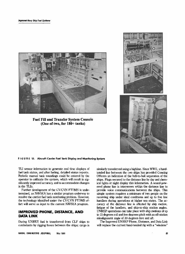
AIRCRAFT CARRIER (CVKVN) FUEL TANK DISPLAY AND MONITORING SYSTEM Currently after refueling, it can take four men up to four hours to manually sound tanks to account for the carrier’s fuel reserves. Manual soundmgs are required because the carrier’s TLI meter readings are too coarse to provide a useful inventory of fuel. Further, the ship’s two fuel system consoles are reported to require excessive maintenance costing up to $0.5M per ship per year.
As requested by NAVSEA, a concept was developed to provide a straightforward, real time method to account for the fuel in an aircraft carrier’s 180 + fuel tanks. The air- craft carrier Fuel Tank Display and Monitoring System (FTDMS) will provide an enhanced and improved TLI display system by interfacing the existing TLI sensors to a microprocessor (PC) based display system. The FTDMS will monitor the CV/CVN JP-5 and/or DFM fuel storage tanks and provide a real time display of all or selected tank levels, detect faulty TLI sensors, and pro- vide an immediate printout of fuel tank status. This infor- mation can be easily transmitted and displayed wherever required on the ship.
The CV/CVN FTDMS would take TLI sensor data and input it to a simple computer-based monitoring, account- ing, and reporting system thereby bypassing most of the console’s interface electronics and panel meters as seen in Figure 13. The FTDMS hardware is composed of COTS components, including an industrial computer, mon- itor, printer, analog-to-digital converters, and connecting cables. The approach is to use an industrial PC in con- junction with a data collection system to process existing
80 May 1999 NAVAL ENGINEERS JOURNAL
Improved Navy Ship Fuel Systems
Fuel Fill and Transfer System Console (One of two, for 180+ tanks)
F I G U R E 13. Aircraft Carrier Fuel Tank Display and Monitoring System
TLI sensor information to generate real time displays of fuel tank status, and after fueling, detailed status reports. F‘eriodic manual tank soundings could be entered by the operator to cahbrate the system, which wdl result in sig- nificantly improved accuracy, and to accommodate changes in the TLIs.
Further development of the CV/CVN FTDMS is unde- termined, as NAVSEA has a similar program underway to resolve the carrier fuel tank monitoring problem. However, the technology identified under the CV/CVN FTDMS ef- fort will serve as input to the current NAVSEA program.
IMPROVED PHONE, DISTANCE, AND DATA LINK During UNRET: fuel is transferred from CLF ships to combatants by rigging hoses between the ships; cargo is
similarly transferred using a highline. Since WWII, a hand- tended line between the two ships has provided Conning Officers an indication of the hull-to-hull separation of the ships. Flags secured to the distance line by day and chem- ical lights at night display this mforrnation. A sound-pow- ered phone line is interwoven within the distance line to provide voice communications between the ships. This simple system requires a minimum of two people on the receiving ship under ideal conditions and up to five line handlers during operations at higher sea states. The ac- curacy of the distance line is affected by ship motion, fatigue of the handlers, and ship-to-ship station angles. UNREP operations can take place with ship motions of up to 15 degrees roll and five degrees pitch with an off-station misalignment angle of 30 degrees fore and aft.
The Improved UNREP Phone, Distance, and Data Link will replace the current hand-tended rig with a “wireless”
NAVAL ENGINEERS JOURNAL May 1999 a1

lmpmved Natty Ship Fuel Systems
system that will sigmfkantly improve communications be- tween ships conducting UNREP operations. The require- ments for a new system are that it have a low probability of intercept, that the operating procedures meet all safety requirements, and that equipment will conform as far as practicable to existing practices. The Improved UNREP Phone, Distance, and Data Link will provide the fdlowlng payoffs: I Reduced UNREP rig complexity will result as the ex-
isting hand-tended phone and distance line would be eliminated.
I Fewer personnel (two or three) would be required per rig by eliminating the hand-tended phone/distance line. A reduction of nine on-deck personnel would be ob- tained during UNREP if a receiving ship were taking one cargo rig, one fuel rig, plus the bridge-to-bridge phone and distance line.
3 h e r risk of personnel injury during UNREP opera- tions, as fewer persons are required on deck.
1 Improved communications will further reduce the risk of parted highlines and spanwires, unseated fuel probes and discharging fuel (pollution), and overpressure dam- age to fuel tanks. Lower risk to ships and cargo through better commu- nications and reduced time for UNREP will reduce risk of damage to cargo, ship collision, and exposure to enemy threat.
TENSWED HOSE FUELING AT-SEA SYSTEM (THFASS) The FAS Standard Tensioned Replenishment Alongside Method (STREAM) suspends fuel hoses under a spanwire connecting the two ships. Components of the system are %-foot lengths of hose and fittings, hose saddles, span-
wire, spanwire winch, three saddle winches, ram ten- sioner, high pressure air, antislack device, and a 56-foot kingpost. The THFASS is based on new tecfinologies in lightweight, high-strength hose, and modern winch drive systems. An important requirement is that THFASS have minimum impact on a receiving ship's FAS stations and procedures. The THFASS will s-tly reduce the appside weight and space, radar cross-sectiool, hardware,
close-in fueling rigs. A comparison of the existing EAS rig and THFASS is shown in Figure 14.
vebpment efforts far improved FAS systems to provide reductions in mechanical compkmty, weight, space, and life cycle costs. Tensioned hose was the most promising concept and was developed based on hghtweight, hgh-
draulic motors as the drive and tensioning mxhnism Devehpmat efforts included break strength, burst, and cyclic tests of candidate hoses, Bdknved ay fkbricah d a small diameter (2.5-kh) "IWMS.
Both small diameter and large diameter (&inch) THFASS rigs have been hitt based rn COTS hardware. The 20O-hoot hose of the small diameter THFASS is spooled onto a single winch drum that is mintakd at a constant tension. The hose is led through a fleeter mech- anism that accommodates ship-to-ship station misalign- ment up to 45 degrees and g m k s the hose onto the reel. Other THFASS components consist of hydraulic pumgs, electric mators, and control system. The small diameter rig was successfully shoreside tested at the Naval susface Warfare Center, Port Hueneme Division UNREP Test Site, and later at sea as seen on Figure 15 with the support of COMLCKXRU TWO.
THFASS offers amphibious warfare ships and aircraft carriers a fuel transfer capability at substantially less cost,
life cycle costs, and is significantly Sa&r than astern anl
The coastal systems station c.mdcted expkwatxx-y de-
strength h o ~ , and L 0 w - w High- 'bp (LSHT) b-
Fuel STREAM TfiFASS Concept
F 1 G U R E 14. Fuel STREAM and THfASS Comparison
a2 May 1999 NAVAL ENGlREERS JlJWRElAL

lmpmved Navy Ship Fuel Syslmns
F I 6 U R E 15. S d l D i m THFASS. At-% ’Ikt
weight, and complexity of the current FAS rig. THFASS eliminates the ktngpost and spanwire and can be installed inside the ship’s hull to satisfy the future requirement for a system that will have a very low Radar Cross Section (RCS) and “low observables” for new design Navy ships.
As illustrated in Figure 16, THFASS could provide the Mine Countermeasures Support Ship (MCS 12) and am- phlbious ships with the capability to efficiently and safely conduct alongside underway refuelmg of mine countermea- sure &IS and other small craft. An important feature of the small diameter TWASS is its ability to refuel smaller ships (PC, PHM, MHC, MCM, and MSO) with greater ship-to-@ separation, i.e., 120 to 180 feet vice 60 to 80 feet. An additional feature of THEASS is its modularity, allowing the rapid instadation of the rig on any Navy or merchant ship capable of providmg fuel to other ships.
Improvements of the Navy’s fuel systems are required to meet current and future environmental requirements. In
the Improved Fuel Fill Control System and the CLF Ship Fuel Transfer Recordmg System, the existing TLIs are augmented by flowmeters to provide a real-time method to detennine both flow rate and accurately record the quantity of fuel transferred. Additionally, sensors could be employed to measure the levels of hydrocarbons in the overboard seawater discharge with the intent of controlling oil-water nixing. The Tensioned Hose Fuelmg At-Sea Sys- tem and the wireless Improved Phone Distance and Data Link will provide a safer, less complex, FAS rigging.
The improvements provided by these and related de- velopments illustrate the fact that relatively low cost off- the-shelf technologies and hardware can have a sigdcant impact on the Fleet’s fuel transfer and storage systems. Further, new technologies can be quickly evaluated and adapted to the shipboard environment through the use of modern design and simulation methods.
W l e q McGawen is a Senior Physicist with the Coastal Systems Station, Dahlgrar Division, Naual Su&e Wa&r$ Centm Mz McGouren has led n u w m caphatory and adwncd development programs contributing toward improve-
+
NAVAL EWGINELRS J O U R M L May 1999 63

lmpmved Navy Ship Fuel Systems
Stream Fueling Escort THFASS Fueling Escort
Ship Installation
Stbd Side View
F I G U R E 16. Carrier and Amphibious Ship THFASS Installation
ment offueling at sea systems, shipboard and shweside materials hundling and stwage, and robotic systems. MK MeGwen has published numerous technical Papers and repwts in the fields of fuel systems, UNREE and automution technology. Mr MccoWen is a member of the ASNE and Association of Unmanned Vehicle Systems. Lloyd Nilsen, RE., is the Fuel and Lubricating Oil Senior Systems Engineer at M V S E A 03132. His career with NAVSEA
includes 38 years of ship design, constructim, and repait; hold- ing various positions in the Power Piping Design Division, Human Factws Manning And Controls Integration Branch, Submarine Machitmy Systems Branch, and Piping Components Branch. M K Nilsen holds a bachelms degree in marine engineer- ing from N . Y State Maritime and is a member ofthe NAVSEA Association of Scientists and Engineers and an active member of the A S M .
84 May 1999 NAVAL ENGINEERS JOURNAL