How to Evaluate Downed Fine Woody Debris Including ... - MDPI

REGULATED RIVERS: RESEARCH & MANAGEMENT, VOL. 12, 223-236 (1996)
HYDRAULIC GUIDELINES FOR THE RE-INTRODUCTION AND MANAGEMENT OF LARGE WOODY DEBRIS IN
LOWLAND RIVERS
CHRISTOPHER J. GIPPEL, IAN C. O'NEILL, BRIAN L. FINLAYSON AND INGO SCHNATZ Centre for Environmental Applied Hydrology, Department of Civil and Environmental Engineering,
The University of Melbourne, Parkville Victoria 3052, Australia
ABSTRACT The volume of large woody debris in most of the world's lowland rivers has been depleted, either through persistent de- snagging or clearance of the riparian vegetation from which it is naturally recruited. The now recognized important environmental role of debris in rivers, the established environmental value of vegetated riparian buffer strips and the movement towards rehabilitation of degraded riverine habitats demand more objective procedures for the management of woody debris in streams. In some instances it may be centuries before the process of natural recruitment of wood from rehabilitated riparian strips achieves an ecologically adequate volume and quality of instream debris. To accelerate this process, the re-introduction of debris is being considered. This paper presents the results of laboratory and field hydraulic investigations relevant to the problem of managing debris in lowland rivers. The laboratory experiments were used to develop a model, based on the momentum principle, of the effect of debris on afflux, or the increase in water surface ele- vation. Debris drag was found to be less affected by position and shape than by orientation to the flow and blockage ratio, or the proportion of the channel occupied by the debris. Debris aligned at 20-30" to the flow produced an afflux one-third of that produced by debris which was perpendicular. Significant loss of conveyance occurs only for debris which is large relative to the channel dimensions (greater than about 10% of the channel area blocked by debris). Wake interference acts to reduce the hydraulic effect of debris so that if spaced within two diameters, multiple in-line items of debris produce an afflux no greater than that of a single item. The models of debris hydraulics presented here can be used to predict the effect of removing, lopping, rotating or re-introducing debris to rivers.
KEY WORDS: large woody debris; river management; snags; hydraulics; drag coefficient; blockage; rehabilitation
INTRODUCTION
Riparian trees that fall into rivers and streams form what is known as snags or large woody debris (debris), conventionally defined as material sized larger than 0.1 or 0.2 m in diameter and 1.0 m in length (Keller and Swanson, 1979; Andrus et al., 1988). Over the past century, the volume of debris in most of the world's low- land rivers has been depleted, either through persistent de-snagging or clearance of the riparian vegetation from which it is naturally recruited. Debris has been systematically removed to maintain navigability, control bank erosion, rejuvenate channels or to maintain or improve the hydraulic capacity of channels (Harmon et al., 1986; Bisson et al., 1987). Natural riparian vegetation has been cleared to make land available for agriculture, remove a refuge for pest species and allow access to the water supply for stock, irrigation or fishing. Most of this work has been undertaken with little regard for the direct or indirect effects on in-stream and riparian biota. However, the broader environmental role of debris is now more widely appreciated (Shields and Nunnally, 1984) and many authorities have recommended or adopted a more sen- sitive approach to its management (e.g. McConnell et al., 1980; International Association of Fish and Wild- life Agencies, 1983; Bilby, 1984; Shields and Nunnally, 1984; Andrus et al., 1988; Department of Conservation and Environment, 1990; Lawrence, 1991). The current emphasis in debris management is to favour the in-stream ecology by removing as little debris as possible.
Degraded stream systems are being rehabilitated in some areas (Gore, 1985; Osborne et al., 1993) and to hasten ecological recovery this can involve replacing debris in previously cleared rivers. The large-scale re-introduction of debris or surrogate enhancement structures to streams has been under way in certain areas
CCC 0886-9375/96/020223- 14 0 1996 by John Wiley & Sons, Ltd.
Received I7 Jury I994 Accepted 19 Jury 1995

224 C. J . GIPPEL ET AL
of the USA for some time (Swales and O’Hara, 1980; Lisle, 1981; Gore, 1985; House and Boehne, 1985; Sedell et al., 1991; Andrus, 1991). In addition, several USA states have declared riparian vegetation manage- ment rules that are partially intended to ensure an ongoing supply of debris to streams (Graf, 1980; Andrus et al., 1988; Sedell et al., 1991). These efforts should speed ecological recovery, but it is likely that ongoing maintenance, in the form of management of in-channel debris or selective logging of riparian vegetation, will be economically and ecologically desirable, especially in lowland areas where flood mitigation is often an issue of concern (Graf, 1980; Rainville et al., 1985; Bisson et al., 1987). A key issue then in debris manage- ment is how to trade off the need to maximize the volume of wood in the channel for ecological benefits against the need to minimize the volume of wood in the channel to lower flow resistance.
Despite the wealth of scientific and engineering publications available on the hydraulics of rivers, guide- lines for debris management still rely on a degree of intuitive judgement, and they lack advice on techniques for conducting reliable quantitative analyses of the hydraulic aspects of the works. Some preliminary work was reported by Young (1991) and a technical report was produced by Gippel et al. (1992). Shields and Gippel (1995) developed a method of predicting the effect of debris removal on flow resistance. The environmental hydraulics of debris have been reviewed by Gippel (1995). This paper presents the main outcomes of a research programme aimed at quantifying the hydraulics of debris in terms of the afflux, or elevation of the water surface upstream of the blockage. The results are used to develop guidelines for the re-introduction and management of debris for hydraulic efficiency.
GENERAL PRINCIPLES OF DEBRIS HYDRAULICS
Like any obstruction, debris generates mutual interference with the flow. One important outcome is the increase in water level, or afflux (Ranga Raju et al., 1983) upstream of the debris. Apart from local disturbance of the velocity profile, debris only has an influence in the upstream direction. An afflux due to blockage by debris means that for the same discharge the water level is higher than without the debris, so flooding frequency is theoretically increased at locations upstream of the blockage. In rivers that are used to convey water for supply to irrigation schemes, debris can cause an afflux large enough to reduce the discharge of water that can be contained within the channel (Gippel et al., 1992). Thus the afflux is a good practical measure of the hydraulic effect of debris. Measuring afflux in the field is difficult, time consuming and site-specific. A modelling approach which predicts the afflux from more easily measured variables is preferable and such a model could be used to assist in planning the re-introduction of debris to rivers that have been de-snagged. The modelling approach adopted here is based on the conservation of momentum principle, which states essentially that the difference in specific force between the river sections upstream and downstream of the debris must equal the drag force exerted by the debris (Henderson, 1966: 266).
At this stage, the momentum approach is applicable only in the case of individual items of debris because it does not account for the wake interference effect of multiple debris. In reality, many debris management problems involve multiple items of debris. An alternative approach to this problem is to estimate the contribution that debris makes to the channel roughness coefficient of a uniform flow equation, such as Manning’s equation (Chow, 1983: 98-127). The problem is that Manning’s equation was developed to describe open channel situations where friction is controlled by surface drag from the bed sediments, rather than form drag from large obstacles such as debris. Also, the hydraulic radius, as conventionally defined in Manning’s equation, is probably meaningless in channels heavily obstructed with debris (Gippel, 1995). An alternative approach was suggested by Shields and Gippel (1995). They developed a method for estimating the effects of debris on flow resistance in rivers on the basis of debris density, channel geometry, mean flow velocity and blockage-dependent debris drag coefficients. Resistance due to bed material, bars and bends was also considered.
HYDRAULICS OF AN INDIVIDUAL ITEM OF DEBRIS
Ranga Raju et at. (1983) used the momentum principle to derive an equation for the amux (Ah) generated by

HYDRAULIC GUIDELINES 225
a cylinder in a confined channel. The momentum principle is only valid where the Froude number is < 1, but it is applicable to the problem of modelling debris hydraulics in most lowland river situations because here the flow is nearly always in the sub-critical range. Using a cylinder as a simple debris model, the equation is
h{(F2 - 1) + [ ( F 2 - 1)2 + 3CDBF2]i} 3 Ah =
where the debris drag coefficient (CD)
and the Froude number at the section downstream of the debris (F)
U F=-
and the blockage ratio ( B )
Ld g=- A
(3)
(4)
and where A = cross-sectional area of flow (m2); d = diameter or width of debris in flow (m); F D = drag force on debris (N); g = acceleration due to gravity (approximately 9.8 m s-~) ; h = water depth downstream of debris (m); L = projected length of debris in flow (m); p = mass density of water (approximately 1000 kg mP3); U , = mean velocity at section upstream of object (ms-'); and U = mean velocity at section down- stream of object (m s-').
For afflux estimation using Equation (l), the Froude number and blockage ratio are easily measured, but CD must be estimated because the drag force cannot be measured in the field. Note that the drag coefficient is expressed relative to the projected area of the object [Equation (2)], so the drag coefficient of a non-symme- trical object (such as debris) will change as its orientation is altered with respect to the flow direction. The drag coefficients of cylinders and other obstacles in flow of infinite extent (no boundary interference), Cb, have been well defined (Hoerner, 1958). Less is known about typical drag coefficients for cylinders confined within boundaries. This is termed the 'blockage effect' and has the effect of increasing the drag coefficient (Shaw, 1971; Ramamurthy and Ng, 1973).
A series of laboratory experiments was conducted to determine the drag coefficient characteristics of model debris. Drag coefficients were determined from Equation (2) by measuring the drag force, with a dynamometer, on debris models in a towing carriage (pool 2m wide by 2m deep) and a flume (0.6m wide). Cylindrical debris models were constructed from closed polyvinyl chloride (PVC) pipes 0.025, 0.048 and 0-076m in diameter and ranging in length from 0.33 to 1.0m. Also, a 1 m long, three-branched, tree-shaped model was assembled from variously sized lengths of PVC pipe. Flume experiments were conducted at three Froude numbers (0.35, 0.47 and 0.63). Angles of orientation to the flow ranged from 0 to 180". By convention 0" is parallel to the flow with the butt end upstream, 90" is perpendicular to the flow direction and 180" is parallel to the flow with the butt end downstream (Gippel, 1995). Velocities ranged from 0.45 to 0.60 m s-l at blockage ratios ranging from 0.03 to 0-40. All experiments were conducted within a sub-critical range of Reynolds' numbers ( 104-105), where the drag coefficient of a cylinder is relatively con- stant (White, 1979: 285). Even at the higher Reynolds' numbers which can occur in rivers, the drag coefficient of debris would not diverge far from the values measured under these conditions (Gippel et al., 1992). The experiments are fully described in Gippel et al. (1992) and only the key results are presented here.

226 C. J. GIPPEL ET AL.
1.4
1.2 0
t 1.0 c.
.g 0.8
5 0.6 u
u 8 0.4
0 0.2
0.0 Oo 10" 20° 30" 40" 50" 60" 70" 80" 90'
I4 Angle of orientation to flow I t-
Figure 1. Variation in drag coefficient with angle of rotation for cylinders of various lengths (L) and diameters (6)
Eflect of angle of orientation in infiniteflow Rotating a cylinder through 90" to the flow direction had a large effect on the drag coefficient, but the
length to diameter ratio of the models was of minor importance to the drag coefficient (Figure 1). For the cylinders of finite length, as their axes approached parallel orientation they projected a bluff face to the flow, resulting in a sharp increase in the drag coefficient.
The drag coefficient of the tree-shaped model was measured at various angles of orientation to the flow and also at four stages of assembly: trunk only (with three short, projecting elbow joiners); trunk and butt (flange); trunk and branches; and complete with trunk, branches and butt (Figure 2). The bluff shape of the butt component produced a high drag coefficient, especially when the model was aligned with the flow direction. With branches present, the drag coefficient varied less with rotation. This was because the branching section had some near-vertical components, the drag of which did not alter with rotation, and some branches became more perpendicular to the flow as the model was initially rotated away from the flow direction. The lower overall drag coefficient for the complete tree-shaped debris model compared with that of the cylinder is explained by the fact that the drag coefficient was expressed relative to the projected surface area. Unlike the simple cylinder model, the branching section was not solid and allowed some flow to pass through it; adding
+Trunk and branchos model +Trunk and bun model
450 90' 135"
Angle of orlentatlon to flow
Figure 2. Variation in drag coefficient with angle of rotation to the flow, measured for tree-shaped models. Broken lines are trendlines fitted to data (0-90" and 90-180" data lumped) for three of the models [Equations (5)-(7)]

HYDRAULIC GUIDELINES 227
a branching component to the simple cylindrical model increased the total drag force, but the drag coefficient was lowered because the increase in projected surface area was proportionally greater than the increased drag force. The short projecting elbow joiners on the trunk-only model gave it drag coefficient characteristics slightly different from those of the simple cylinder (Figure 1).
Drag coefficients (Cb) for the trunk model, the trunk and branches model and the complete tree-shaped model were modelled as functions of the angle (in degrees) of orientation to the flow (9). For these cases, the trends for butt upstream (0-90") and butt downstream (90- 180") orientation were similar, so the data were lumped ( N = 10). A simple model could not be fitted to the data for the trunk and butt model because the trends for upstream and downstream orientation were different. The following best-fit empirical models (Figure 2) were derived (SEE = standard error of estimate)
for the complete tree-shaped model
Cb = 0.5060 + 1.8200E = 39 (SEE = 0.046, R 2 = 0 . 6 6 4 , ~ = 0.004) ( 5 )
for the trunk and branches model
Cb = 0.3570 - 2.2196E - 49 + 1.1273E - 4g2 - 7.9338E - 7g3
(SEE = 0-022, R 2 = 0 . 9 7 8 , ~ = 0.0001)
for the trunk only model
Cb = 1.1 173 - 5.28008 - 29 + 1.4385E - 3g2 - 9.7668E - 603
(SEE = 0.075, R 2 = 0 . 9 8 5 , ~ = 0.0007) (7)
Eflect of distance from bed in con$ned$ow The blockage effect of confined flow does not alter the inherent drag coefficient of the cylinder. Rather, C,
measured in confined flow is an 'apparent' drag coefficient, defined with respect to the upstream mean velocity. The drag coefficient of a horizontal cylinder did not measurably vary with proximity to the flume walls. However, depending on the experimental conditions, substantial variation was observed with distance from the bed and water surface (Figure 3). The distance of the cylinder from the bed was expressed as relative
+F - 0.47, h I 0.14 m, B - 0.27
+F-0.35, h.0.25m,B-0.16 4 0 0.2 0.4 0.6 0.8 1 .o
Relatlve depth of cylinder
Figure 3. Variation in horizontal cylinder drag coefficient with depth from the bed for three particular cases of Froude number (F), blockage ratio (B) and flow depth (h)
228 C. J . GIPPEL ET AL.
depth, which is the distance from the base of cylinder to the bed as a proportion of the total flow depth. The wake was disturbed to a varying degree depending on the vertical position of the cylinder. Dye tests
indicated that when the cylinder was close to the bed a zone of near-zero velocity (saddle point) developed upstream of the cylinder, causing the apparent drag coefficient to be high. This dead zone dissipated as the model was elevated and CD decreased. The drag coefficient remained relatively constant with relative height for the cylinder in a water depth of 0.25 m. As the cylinders were raised close to the water surface, critical flow conditions occurred and CD dropped sharply (Figure 3).
In most lowland river situations, where the Froude number is below 0.5, the blockage ratio is below 0.3 and the debris diameter is less than one-third of the flow depth, the depth dependency of debris CD is too small to be an important management consideration. Therefore, C, can be considered constant with depth.
Efect of blockage in conjinedpow Flume experiments clearly demonstrated the importance of the blockage ratio in determining the cylinder
drag coefficient, although the effect was limited by the Froude number. Regression of the results of 50 experiments using single and stacked cylinders, conducted at Froude number 0.35, and blockage ratios ranging from 0.03 to 0.30, resulted in the following relationship for the drag coefficient [plotted with confidence intervals in Shields and Gippel(1995)], where C', is the drag coefficient measured in infinite flow
Practical application of models For the range of conditions that usually prevail in lowland rivers, the laboratory experiments indicated
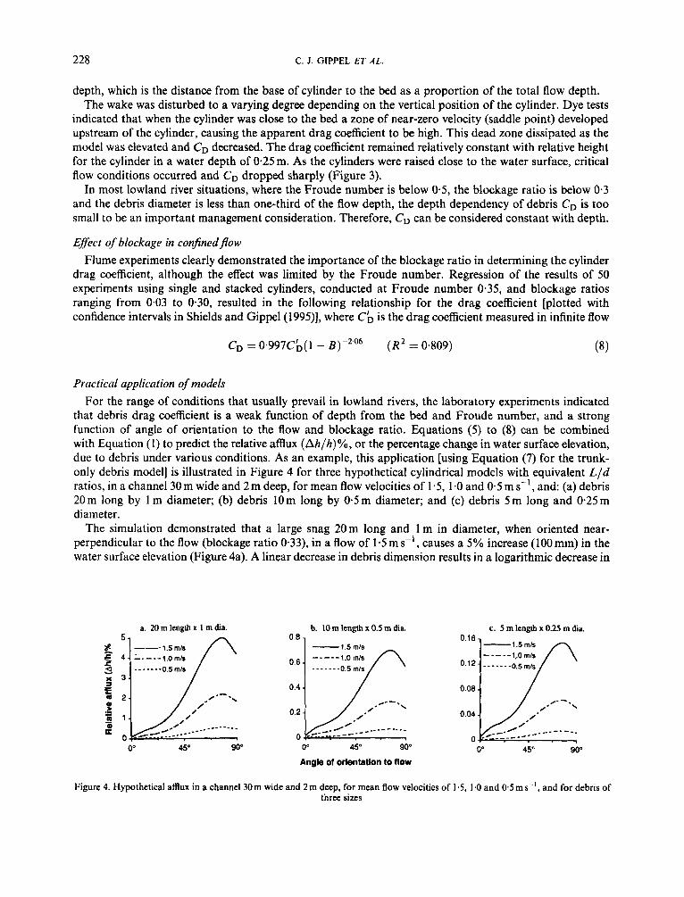
that debris drag coefficient is a weak function of depth from the bed and Froude number, and a strong function of angle of orientation to the flow and blockage ratio. Equations ( 5 ) to (8) can be combined with Equation (1) to predict the relative amux (Ah/h)%, or the percentage change in water surface elevation, due to debris under various conditions. As an example, this application [using Equation (7) for the trunk- only debris model] is illustrated in Figure 4 for three hypothetical cylindrical models with equivalent L / d ratios, in a channel 30 m wide and 2 m deep, for mean flow velocities of 1-5, 1.0 and 0.5 m s-l, and: (a) debris 20m long by 1 m diameter; (b) debris 10m long by 0.5 m diameter; and (c) debris 5 m long and 0.25 m diameter.
The simulation demonstrated that a large snag 20m long and 1 m in diameter, when oriented near- perpendicular to the flow (blockage ratio 0.33), in a flow of 1.5 m s-l, causes a 5% increase (100 mm) in the water surface elevation (Figure 4a). A linear decrease in debris dimension results in a logarithmic decrease in
a. 20 m length x 1 m dia.
- . 0" 450 90"
b. 10 m length x 0.5 rn dia. 0.8
1.5 mls 1 .O rnls
0.2
_ _ - ----__ _ _ _ -- - - - 0" 450 90"
Angle of orlentation to flow
c. 5 m length x 0.25 m dia. 0.16
-1.5mh 1,O mls
0.08
0.04 /-
0" 450 90"
Figure 4. Hypothetical afflux in a channel 30m wide and 2m deep, for mean flow velocities of 1.5, 1.0 and 0.5 m s-', and for debris of three sizes

HYDRAULIC GUIDELINES 229
afflux. A small item of debris in a low velocity flow produces an afflux so small that it would be difficult to detect it in the field (Figure 4c). Rotating the debris away from the perpendicular results in a substantial reduction in the afflux. Afflux is insignificant for flow-parallel debris under the conditions tested.
The outlined approach was used to model affluxes caused by debris that were measured on the Tumut River, NSW, Australia (Gippel et al., 1992). The bank-top channel width ranged from 30 to 50m and the water depth at this flow was about 2.5m. The mean velocity of bank-top flow (100m3s-') was about 1 m s-'. Debris formations occupying 2-40% of the channel cross-section were observed to cause affluxes of up to 230 mm (9% of flow depth). Equation (1) predicted affluxes of 4 and 1 mm for small snags with blockage ratios below 0.06 that did not produce a measurable afflux. For two large debris formations, Equation (1) under-predicted the measured affluxes by 50 and 60%. This is a reasonable error, because Equations (1) and (7) are very sensitive to debris dimensions and flow velocity and problems were experienced in obtaining accurate and meaningful data for these parameters. It was difficult to accurately measure the debris dimensions, given the size of the river and the depth and velocity of the flow. Probably more significantly, the alternate arrangement of debris along the banks produced a meandering pattern of high flow within the channel and the reach mean velocity underestimated (by up to 50%) the actual approach velocity of the flow at the debris formations.
The upstream extent of the 230mm aaux on the Tumut River was computed by MIKE 1 1 (Danish Hydraulic Institute, 1988) using a standard backwater modelling procedure. The problem was simplified by assuming a constant river cross-sectional shape upstream. This procedure estimated that the afflux would persist (i.e. > 10mm) for a distance of about 3 km upstream of the debris formation, but it would decline to about half of its initial value at a point approximately 1 km upstream (Gippel et al., 1992).
Equation (1) was used to model the afflux due to debris in a 775 m reach of the lower Thomson River, Victoria, Australia (Gippel et al., in press). Under bank-top flow conditions (estimated 109 m3 s-'), the estimated affluxes due to each of the 95 items of debris present ranged from almost zero to 1.3 mm, with the median value being 0.03 mm. The sum of the affluxes was 8.6 mm, or 0.2% of the flow depth. In reality, affluxes would decline appreciably over a reach of 775 m, so this sum exaggerates the total effect. Also, the wake interference between closely spaced items of debris would act to lower the drag. The small calculated amux is explained by the generally narrow angle of orientation of the debris to the flow (median of 27" to the flow) and therefore small projected cross-sectional areas (median of 1 m2). Thus the blockage ratios were also low, ranging from 0.0002 to 0.100, with a median value of only 0.004. From Figure 4c it can be seen that such conditions produce only small affluxes. The largest item of debris accounted for 15% of the total afflux and the 10 largest items accounted for 57% of the total afflux (Gippel et al., in press).
HYDRAULICS OF MULTIPLE ITEMS O F DEBRIS
Two approaches were taken to characterizing the hydraulics of multiple items of debris. The first approach was to use the previously described force measuring apparatus to measure the drag coefficient of various arrangements of debris models. This was of limited success for practical reasons that are described in the following. The second approach was to directly measure the afflux produced by model debris fields.
Drag characterisiics of multiple debris In the case of two equal cylinders placed one behind the other at a distance of no more than two diameters,
the drag of the forward cylinder is lower than it would be in infinite flow. This is because the rear cylinder acts to reduce vortex formation. Also, the boundary layer of the rear cylinder is made turbulent by the wake of the forward cylinder, thus producing a super-critical flow pattern with a correspondingly lower drag coeffi- cient (Hoerner, 1958: 8-1). Hoerner (1958) described the combined result of these two effects as a counter- intuitive phenomenon: up to a separation distance of approximately two diameters, the combined drag of two cylinders is less than that of a single isolated cylinder. As the spacing increases, the drag of the rear cylin- der gradually approaches that of an isolated cylinder (Young, 1991). Nagai and Kurata (1971) found that the influence of a second cylinder on drag was not significant when the spacing was greater than 15 diameters.
Difficulties were experienced in attempting to measure the drag coefficient of multiple cylinders placed

230 C. J. GIPPEL ET AL.
horizontally in-line using the previously described force-measuring apparatus. When the vortex shedding frequency (see Gordon et al., 1992: 250-252, for an explanation of vortex formation and shedding) coincided with the natural frequency of the dynamometer, resonant vibration of the apparatus occurred. Multiple debris accentuated the problem and certain spacings created vibration so excessive that measurement of the drag force was not possible. However, some limited tests were carried out with multiple in-line cylinders. The drag coefficients of groups of 3, 5,7 ,9 and 13 horizontally in-line cylinders (0,025 x 0.455 m) were mea- sured in the flume at various separation distances.
The average drag coefficient for any given spacing decreased as the number of cylinders increased. This is explained by the first cylinder having a higher drag coefficient than any following cylinder. This trend was observed at zero spacing such that the average drag coefficient for a group of three cylinders was 0.4, whereas for 13 cylinders it was 0.2. As the spacing was increased, vibration of the force-measuring apparatus made accurate measurement difficult, but it was generally observed that beyond approximately four diameters separation distance, the average drag coefficient of each cylinder in a group of in-line cylinders approached a value of 0.8-1 .O. Theoretically, as the separation distance increases, the wake from the preceding cylinder will have dissipated sufficiently so that each cylinder acts independently.
A@ux produced by multiple debris Belds Experiments were conducted in a laboratory flume to measure the afflux caused by multiple items of
debris. The glass-walled flume was rectangular in cross-section, 8 m long, 0.456m wide and had a slope of 0.025%. Flow conditions were controlled by a broad-crested weir located at the flume outlet. The experi- mental conditions were set at 1 : 40 length scale and Froude number similarity was maintained (Yalin, 1971). Assuming a Froude number of 0.16, the experimental flow conditions were a depth of 100 mm and a velocity of 0.1 55 m s-' . The cylindrical wooden debris models ranged in length from 0.1 to 0.456 m and were either 0-025 or 0.01 m in diameter. This scales to a prototype river 4 m deep and 18 m wide, with a flow velocity of 1 m s-' and containing debris between 4 and 18 m in length and 0.4 and 1 m in diameter. The debris was attached to the wooden bed of the flume over a 1 m long test section. Afflux was measured upstream of the debris models using a point gauge with a vernier scale that allowed measurements to the nearest 0.1 mm. All measurements were repeatable within this level of accuracy.
The first set of experiments involved groups of two, three, four, five, six and seven cylinders (0.025 m in diameter), perpendicular to the flow, progressively spaced at distances ( j ) ranging from zero (touching) to 10 diameters ( d ) . It is of considerable interest that a group of seven cylinders, when spaced less than two diameters apart, produced an afflux that was the same as, or lower than, that of a smaller group of cylin- ders similarly spaced (Figure 5). At this separation distance, skimming flow (Morris, 1955) occurs, with dead velocity zones between the cylinders. The group of cylinders acts hydraulically as a long, smooth, continuous object, which exerts a lower drag than a short object with the same frontal shape and dimensions. Similar observations were made by Knight and Macdonald (l979), who classified the flow patterns produced by
4 f
1.6-
1 .4 -
1.2 - 1.0-
0.8.
0.6. ---A- -. 6 elements
._.-*-
0.4
0.2
0.04 , . . . , , . . . I
0 1 2 3 4 5 6 7 8 9 10 Spacing U/d)
Figure 5. Measured afflux due to multiple in-line cylinders spaced at distances ( j ) equivalent to zero to 10 diameters ( d )

HYDRAULIC GUIDELINES 23 I
Perspex (acrylic resin) square-sectioned strips in a flume. Skimming flow occurred when the spacing of the strips was less than 3.5 times their height. The results (Figure 5) suggest that debris clumped two to four diameters apart is hydraulically very efficient. This may help explain why clumping of debris is often observed in lowland rivers (Bisson et al., 1987; Gippel et al., 1992). Even when spaced up to 10 diameters apart, wake interference acted to lower the drag on the cylinders, so that the afflux contributed by each cylinder (averaged) was about one-third of that produced by an isolated cylinder (Figure 5).
The second set of flume experiments involved creating scale models of debris fields such as those found in undisturbed lowland rivers. For practical reasons, the laboratory debris fields were constructed from a relatively limited range of debris models. No attempt was made to construct a scale model of an actual reach of river. Rather, using simple cylindrical models debris fields were arranged so that in orientation and volume, their distributions roughly resembled those observed in the Thomson River, Victoria (Gippel et al., in press).
The model debris fields consisted of 24 cylinders of various dimensions placed over the 1 m long test section. The cylinders were 0.1 m long (four cylinders), 0.2m long (16 cylinders) and 0.4m long (four cylinders). Two diameters were used, 0.025 m (six cylinders) and 0.01 m (18 cylinders). The maximum volume loading over the test section was 0.0022 m3 m-* (compared with 0.0033 m3 m-* measured in a reach of the Thomson River). The cylinders were oriented at angles to the flow of 10" (one cylinder), 20" (six cylinders), 25" (eight cylinders), 30" (two cylinders), 45" (four cylinders), 90" (two cylinders) and 150" (one cylinder). The angle of orientation of each cylinder was randomly allocated within these constraints. The position along the test section of each cylinder was randomly allocated and their position across the section was randomly allocated as either left (one end touching the left flume wall), right (one end touching the right flume wall) or central (mid-point of cylinder centrally located). The cylinders were progressively screwed to the bed of the flume (or underlying cylinder if present) in their allocated position and angle of orientation in ascending order from lowest volume (0.01 x 0.1 m cylinder) to largest volume (0.025 x 0-4m cylinder). This resulted in some cylinders overlapping, not touching the bed and lying at slight angles to the horizontal, as occurs in an actual river. The water surface elevation was measured each time a cylinder was introduced. A check of the measurements as the cylinders were removed in descending order showed that the results were repeatable within the level of accuracy of the point gauge. The experiment was conducted three times, on each occasion using a different distribution of randomly allocated cylinder positions and angles of orientation (Figure 6) .
+--0.456rn+ -1
C
Figure 6. Experimental scale model distributions of debris fields, based on that found in an undisturbed reach of the lower Thomson River, Victoria, Australia

232 C. J . GIPPEL ET A t .
1 .67
0.0000 0.0005 0.0010 0.0015 0.0020 0.0025
Debrls volume (m3 m-*)
Figure 7. Affluxes caused by progressive introduction of debris distributed in the form of three scale model debris fields
As expected, the three distributions produced different affluxes, but the trends were similar (Figure 7). Up to 12 of the small, low volume cylinders could be introduced without producing a measurable afflux (distributions A and C ) . Introduction of the group of medium-sized cylinders contributed about half of the eventual afflux. The largest increase in the afflux occurred when the largest (distributions B and C ) or the second largest (distribution A) cylinders were introduced. These results indicate the importance of the position and angle of orientation of the two largest cylinders. These large elements produced less afflux the deeper they were positioned in the wake interference zone produced by other cylinders, or the more they were angled away from the flow direction. This explains why distribution A produced the lowest total afflux; the largest element was angled close to the flow direction and was shielded by many other elements.
The affluxes produced by the model debris fields were modest, ranging from 0.8 to 1.5% of the flow depth. These are higher than the afflux predicted for the surveyed Thomson River debris (0.2%), but the conditions in these two situations were not sufficiently close to allow direct comparison. The flume was proportionately half as wide as the river channel. Also, although the debris volume loading in the flume was similar to that in the river, most of the debris in the flume was proportionately much larger in diameter. These factors produced higher blockage ratios in the flume. The blockage ratios in the river ranged from 0.0002 to 0.100, with a median of 0.004 (Gippel et al., in press), whereas in the flume they ranged from 0.008 to 0.1 55 with a median of 0.022.
Estimates of the total affluxes for distributions A, B and C using Equation ( I ) were 0.73,0.70 and 0.79%, respectively. As explained previously, when debris elements are grouped in-line, the effect of wake interference is to lower the total afflux compared with the sum of the individual affluxes. Although this effect must have been operating in the flume experiment (Figure 6) , the measured total affluxes were higher than those estimated, particularly for distribution C (Figure 7). The method of summing individual affluxes calculated using Equation ( I ) underestimated the total affluxes in these instances because it failed to account for lateral interactions between neighbouring debris elements. For example, in distribution C , placement of the final two debris elements resulted in the full width of the channel being occupied by debris at that point (Figure 6) . In isolation, the sum of the estimated affluxes for these two elements was 0*23%, whereas in practice, placement of these elements caused the afflux to increase from 0.8 to 1.5% (Figure 7). Assuming that these elements effectively acted as one element, perpendicular to the flow and having a blockage ratio of 0.25, the calculated afflux was 0.55%. This was close to the measured increase in afflux that occurred when they were placed in the flume. The synergistic effect of lateral interaction may help explain why the magnitude of the affluxes on the Tumut River were underestimated.
GUIDELINES FOR HYDRAULIC MANAGEMENT OF DEBRIS
Volume of debris Debris volume loadings within the range 0.001-0.1 m3 m-’ are found in relatively undisturbed lowland

HYDRAULIC GUIDELINES 233
rivers draining catchments greater than 100 km2 (Gippel, 1995; Gippel et al., in press). In the absence of local data, 0.01 m3 m-2 could be used as a reasonable aim for debris management programmes in lowland rivers. Modelling suggests that the debris in the Thomson River, Victoria, Australia would have a minor hydraulic effect by producing an afflux of only 0.2% of the bank-top flow depth. This is because the debris found in the Thomson River was small in dimension relative to the size of the channel, with the median diameter of the debris being equivalent to only 10% of the bank-top flow depth. Volume loadings of this order could produce significant increases in water surface elevation if the debris was blocking a large percentage of the channel cross-section. For example, on the Tumut River, Australia two adjacent debris formations blocking 40 and 38% of the channel area produced a combined aflux equivalent to 9% of the bank-top flow depth.
There is some published evidence that unmanaged lowland rivers could develop very high loadings of debris. For example, Sedell and Froggatt (1984) established that in the Willamette River, Oregon (a ninth- order river), before large-scale removal beginning in 1858, downed trees occurred at an average density of 630 km-' of channel. Their average size was 30-60 m in length and 0.5-2-0 m in diameter. Debris density in the River Murray, Australia must have been high before persistent de-snagging efforts began in the last century, because as recently as the period 1976-1986 it was still possible to remove 22 000 items of debris from a 233 km reach (Gippel et at., 1992). Early explorers often commented on the density of debris in the large inland draining rivers of south-eastern Australia, with one surveyor encountering 'perfect walls of tim- ber' (Lloyd, 1988: 87-88). Sedell and Froggatt (1984), Triska (1984) and Gurnell and Gregory (1981) sug- gested that in undisturbed systems debris is a major determinant of channel morphology. A review of the hydraulic effect of debris (Gippel, 1995) found some evidence suggesting that a very heavy build-up of debris could significantly alter stream hydrology, and this is supported by the experimental and field results reported here. Thus in areas where channel stability and flood protection are issues of concern, river rehabilitation programmes should plan for on-going debris maintenance in the form of lopping, rotation or selective removal.
Management of debris for hydraulic eficiency It is now generally accepted that in-stream debris is ecologically desirable, but in many lowland river
situations where the conveyance of irrigation flows or flooding are important issues, managers are reluctant to compromise the hydraulic efficiency of the channel. The most hydraulically efficient debris is small in dimension relative to the channel, aligned with the flow, and located on the channel margins and other areas of low flow velocity. However, it is likely that the hydraulic habitat associated with debris is very dependent on factors such as size, position and orientation. In general, hydraulic diversity is ecologically desirable, but debris is particularly recognized for providing zero or near-zero velocity zones that are utilized by fish for resting and refuge (Gippel, 1995). In undisturbed lowland rivers, debris is distributed across a range of sizes, orientations and positions, so given a lack of specific habitat preference information, some variability should be maintained in managed systems.
Angle of orientation to rhe$ow. For debris to rotate, the drag force must overcome the friction force of the debris in contact with the bed and banks. This frictional resistance tends to prevent debris from aligning parallel with the flow (where the drag force is lowest). Thus it is natural for debris to be located at a moderate angle to the flow direction. For example, in the lower Thomson River the median orientation angle of debris was 27", with 65% of the debris being angled at less than 40". It is clear from the data in Figure 4 that three hydraulically independent items of debris angled at 20-30" produce a combined afflux of about the same magnitude as a single item of debris of the same dimension oriented perpendicular to the flow.
Separation distance. For similarly sized items of debris, the resistance lowering effect of wake interference applies mainly within a separation distance of four diameters. The results of the flume studies (Figure 5 ) suggest that if spaced within two diameters, up to six items of debris placed in-line will produce an afflux no greater than that of a single item of debris. In the case of debris items that are in close proximity across the channel, for the purpose of afflux estimation they should be treated as one item.
In practice, debris in rivers is not geometrically arranged and it varies widely in dimension, so the wake

234 C. J. GIPPEL ET AL
interference pattern is complex. Thus modelling the effect of wake interference on the afflux produced by multiple debris is a difficult problem. However, as a general rule, for maximizing both the hydraulic efficiency and the area of zero or near-zero velocity zones, debris should be located within two to four diameters. Debris clumped close together and in-line is more hydraulically efficient than widely separated isolated items of debris, or debris placed close together across the channel.
Debris dimensions. It is the size of the debris relative to the channel dimensions that is hydraulically important, rather than the absolute size of the debris. Under most lowland river situations, debris must block more than about 10% of the flow cross-sectional area to produce an afflux large enough to be detectable in the field. Hydraulic assessment of debris in a congested reach should focus on the largest items. Small items of debris are hydraulically innocuous and little benefit would be gained from their removal. Lopping of branches will improve hydraulic efficiency, but in many instances this could present practical difficulties and, with time, branches naturally decay and break off. Branches near the bank-top water surface level should be lopped if the debris has a tendency to trap smaller pieces and form large accumulations.
Debris in undisturbed rivers is present in a range of sizes and this probably contributes to habitat diversity. Debris re-introduction programmes should also aim for size diversity. It should be possible to reduce the drag coefficient (and therefore afflux) of a large, bluff-shaped item of debris by placing upstream a series of closely spaced, progressively smaller items. This will give the overall agglomeration of debris a more streamlined shape.
Debris position. The magnitude of the afflux caused by debris is highly dependent on flow velocity. Movement of debris away from the high velocity zone in the centre of the channel will improve the hydraulic efficiency. However, this action could increase the maximum velocities in the centre of the channel, possibly leading to mobilization of bed sediments and thus deepening of the thalweg. For hydraulic efficiency and stability, debris should be placed in zones of low velocity along the channel margins or on the inside of meanders. It should be expected that over time the debris will be re-distributed by high flows and morphological channel changes.
Modelling the hydraulic eflect of debris A method has been proposed to model the hydraulic effect of an individual item of debris in lowland rivers.
The model predicts the afflux, or increase in the water surface elevation, caused by debris. The following method should be used.
1. Measure the projected area and angle of orientation to the flow of the debris. 2. Measure the cross-sectional area of the channel at the level of the discharge of interest. 3. For the discharge of interest, measure or estimate the depth and velocity of the flow downstream of the
debris. 4. Select an appropriate drag coefficient from Figures 1 or 2, or use Equations (9, (6 ) or (7). 5 . Calculate the Froude number and blockage ratio. 6 . Correct the drag coefficient for blockage using Equation (8). 7. Estimate the afflux using Equation (1). 8. If required, calculate the upstream extent of the afflux using a backwater procedure.
The proposed method of calculating afflux due to individual items of debris could be used as a tool to help determine which debris should be removed and which is hydraulically benign. For debris requiring management, the method can be used to predict the reduction in afflux that would be achieved by removal, rotation or lopping. The method could also be used in stream rehabilitation schemes to help plan the re-introduction of debris without causing undesirable hydraulic effects.
ACKNOWLEDGEMENTS
The project was funded by the Land and Water Resources Research and Development Corporation in partnership with the Department of Water Resources, NSW, the Water Resources Management Branch

HYDRAULIC GUIDELINES 235
of the Department of Conservation and Natural Resources, Victoria, and the Rural Water Corporation of Victoria.
REFERENCES
Andrus, C. 1991. Improving Streams and Watersheds in Oregon, Inventory and Evaluation ofEfforts io Improve the Condition ofOregon’s Streams and Watersheds from 1985 to 1990. Resource Management Division, Water Resources Department, Salem, Oregon. 31 pp.
Andrus, C. W., Long, B. A., and Froehlich, H. A. 1988. ‘Woody debris and its contribution to pool formation in a coastal stream 50 years after logging’, Can. J. Fish. Aquat. Sci., 45, 2080-2086.
Bilby, R. E. 1984. ‘Removal of woody debris may affect stream channel stability’, J. Forestry, 82, 609-613. Bisson, P. A., Bilby, R. E., Bryant, M. A., Dolloff, A. A., Grette, G. B., House, R. A., Murphy, M. L., Koski, K. V., and Sedell, J. R.
1987. ‘Large woody debris in forested streams in the Pacific Northwest, past, present and future’ in Salo, E. 0. and Cundy, T. W. (Eds), Streamside Management. Forestry and Fishery Interactions. College of Forest Resources, Univ. Washington. Znst. Forest Resources, Conrrib. No. 57. Seattle, Washington, 143-190.
Chow, V. T. 1983. Open Channel Hydraulics. International Student Edition. McGraw-Hill, Tokyo. 680 pp. Danish Hydraulic Institute 1988. MZKE 11 User’s Guide. Danish Hydraulic Institute. Department of Conservation and Environment 1990. Environment Guidelines for River Management Works. Office of Water Resources,
Gippel, C. J. 1995. ‘Environmental hydraulics of large woody debris in streams and rivers’, J. Environ. Engin., 121,388-395. Gippel, C. J. ‘Distribution and hydraulic significance of large woody debris in a lowland Australian river’, Hydrobiologiu, in press. Gippel, C. J., ONeill, I. C., and Finlayson, B. L. 1992. The Hydraulic Basis of Snag Management. Centre for Environmental Applied
Gordon, N. D., McMahon, T. A,, and Finlayson, B. L. 1992. Stream Hydrology: an Introduction for Ecologists. Wiley, Chichester. Gore, J. A. 1985. ‘Mechanisms of colonization and habitat enhancement for benthic macroinvertebrates in restored river channels’ in
Graf, W. L. 1980. ‘Riparian management, a flood control perspective’, J . Soil War. Conserv., 35, 158-161. Gurnell, A. M. and Gregory, K. J. 1981. ‘The influence of vegetation on stream channel processes’ in Burt, T. P. and Walling, D. E.
(Eds), Catchment Experiments in Geomorphology. GeoBooks, Norwich. pp. 5 15-535. Harmon, M. E., Franklin, J. F., Swanson, F. J., Sollins, P., Gregory, S . V., Lattin, J. D., Anderson, N. H., Cline, S. P., Aumen, N. G.,
Sedell, J. R., Lienkaemper, G. W., Cromack Jr, K., and Cummins, K. W. 1986. ‘Ecology of coarse woody debris in temperate ecosystems’, Adv. Ecol. Res., 15, 133-302.
DCE, VGPO, Melbourne, Victoria. 58 pp.
Hydrology, Department of Civil and Agricultural Engineering, The University of Melbourne, Parkville. 1 16 p.
Gore, J. A. (Ed.), The Restoration of Rivers and Streams. Theories and Experience. Butterworth, Boston. pp. 81-101.
Henderson, F. M. 1966. Open Channel Flow. MacMillan, New York. 522 pp. Hoerner, S. F. 1958. Fluid Dynamic Drag. Self-published, New Jersey. House, R. A. and Boehne, P. L. 1985. ‘Evaluation of instream enhancement structures for salmonid spawning and rearing in a coastal
International Association of Fish and Wildlife Agencies 1983. Stream Obstruction Removal Guidelines. Stream Renovation Guidelines
Keller, E. A. and Swanson, F. J. 1979. ‘Effects of large organic material on channel form and fluvial processes’, Earth Surf. Process., 4,
Knight, D. W. and Macdonald, J. A. 1979. ‘Hydraulic resistance of artificial strip roughness’, J. Hydr. Div., Proc. A X E , 105 (HY6),
Lawrence, B. W. 1991 Draft Fish Management Plan. Murray-Darling Basin Commission, Canberra. 48 pp. Lisle, T. E. 1981. ‘Roughness elements, a key resource to improve anadromous fish habitat’ in Hassler, T. J. (Ed.), Proceedings o f a
Symposium on Propagation, Enhancement, and Rehabilitation of Anadromous Salmonid Populations and Habitat in the Pacific Northwest. Humboldt State University, Arcata. pp. 93-98.
Lloyd, C. 1988. Either Drought or Plenty: Water Development and Management in New South Wales. Department of Water Resources New South Wales, Kangaroo Press, Sydney. 31 1 pp.
McConnell, C. A., Parsons, D. R., Montgomery, G. L., and Gainer, W. L. 1980. ‘Stream renovation alternatives, the Wolf River story’, J. Soil W a f . Conserv., 35, 17-20.
Morris, H. M. 1955. ‘Flow in rough conduits’, Trans. Am. SOC. Civ. Engin., 120,373-398. Nagai, S . and Kurata, K. 1971. ‘Interference between cylinders in an open channel flow’, Trans. Jpn Soc. Civ. Engin., 3, 200-201. Osborne, L. L., Bayley, P. B., Higler, L. W. G., Statzner, B., Triska, F., and Iversen, T. M. 1993. ‘Restoration of lowland streams: and
Rainville, R. C., Rainville, S. C., and Linder, E. L. 1985. ‘Riparian silvicultural strategies for fish habitat emphasis’ in Tech. Rep. 37.
Ramamurthy, A. S. and Ng, A. M. 1973. ‘Effect of blockage on steady force coefficients’, J. Engin. Mech. Div. Proc. ASCE, 99 (EM4),
Ranga Raju, K. G., Rana, 0. P. S. , Asawa, G. L., and Pillai, A. S. N. 1983. ‘Rational assessment of blockage effect in channel flow past smooth circular cylinders’, J . Hydr. Res., 21,289-302.
Sedell, J, R. and Froggatt, J. L. 1984. ‘Importance of streamside forests to large rivers: the isolation of the Willamette River, Oregon, U.S.A., from its floodplain by snagging and streamside forest removal’, Yerh. Inr. Verein. Limnol., 22, 1828-1834.
Sedell, J. R., Steedman, R. J., Regier, H. A., and Gregory, S. V. 1991. ‘Restoration of human impacted land-water ecotones’ in Holland, M. M., Risser, P. G. and Naiman, R. J. (Eds), Ecotones: the Role of LanLcape Boundaries in the Management and Restoration of Changing Environments. Chapman and Hall, London. pp. 110-129.
Oregon stream’, North Am. J. Fish. Manage., 5, 283-295.
Committee, Washington.
361-380.
675-690.
introduction’, Freshwater Biol., 29, 187-194.
Proc. 1985 National Convention. Society of American Foresters, Bethesda. pp. 186- 196.
755-772.
Shaw, T. L. 1971. ’Effect of side walls on flow past bluff bodies’, J. Hydr. Div., Proc. ASCE, 97 (HYI), 65-79. Shields, F. D. Jr and Gippel, C. J. 1995. ‘Prediction ofeffects ofwoody debris removal on flow resistance’, J . Hydr. Engin., 121,341-354.

236 C. J . GIPPEL ET ,415
Shields, F. D. Jr and Nunnally, N. R. 1984. ‘Environmental aspects of clearing and snagging’, J . Environ. Engin., 110, 152-165. Swales, S. and OHara, K. 1980. ‘Instream habitat improvement devices and their use in freshwater fisheries management’, J. Environ.
Triska, F. J . 1984. ‘Role of wood debris in modifying channel geomorphology and riparian areas of a large lowland river under pristine
White, F. M. 1979. Fluid Mechanics. McCraw-Hill, New York. 701 pp. Yalin, M. S. 1971. Theory of Hydraulic Models. MacMillan, London. Young, W. J. 1991. ‘Flume study of the hydraulic effects of large woody debris in lowland rivers’, Regul. Riv., 6, 203-21 I .
Manage., 10, 167- 1 79.
conditions, a historical case study’, Verh. In?. Verein. Limnol., 22, 1876-1892.
Copyright © 2022 FDOKUMEN