
Human tracking from a mobile agent: Optical flow and Kalman filter arbitration
13
Human tracking from a mobile agent: Optical flow and Kalman filter arbitration Yuichi Motai n , Sumit Kumar Jha, Daniel Kruse Virginia Commonwealth University, School of Engineering, 601 West Main Street, PO Box 843068, Richmond, VA 23284-3068, USA article info Article history: Received 5 November 2010 Accepted 23 June 2011 Keywords: Human tracking Kalman filter Mobile robot Optical flow abstract Tracking moving objects is one of the most important but problematic features of motion analysis and understanding. The Kalman filter (KF) has commonly been used for estimation and prediction of the target position in succeeding frames. In this paper, we propose a novel and efficient method of tracking, which performs well even when the target takes a sudden turn during its motion. The proposed method arbitrates between KF and Optical flow (OF) to improve the tracking performance. Our system utilizes a laser to measure the distance to the nearest obstacle and an infrared camera to find the target. The relative data is then fused with the Arbitrate OFKF filter to perform real-time tracking. Experimental results show our suggested approach is very effective and reliable for estimating and tracking moving objects. & 2011 Elsevier B.V. All rights reserved. 1. Introduction Human tracking using mobile robots serves a lot of attention because an automated system estimating and tracking moving objects has many potential applica- tions in the field of surveillance and engineering [46]. The mobile robot target tracking mechanism essentially needs the motion analysis of the target behavior. A number of approaches on prediction and tracking are based on the traditional Kalman filter (KF) [10–15]. In the KF approach, it is presumed that the behavior of a moving target could be characterized by a predefined model, and the models can be represented in terms of a state vector. In reality, however, these models fail to characterize the motion of moving targets accurately. As a result of this, KF fails to track a target, especially when there are occlusions caused by other objects or sudden changes in the trajectory of the motion [13]. In this paper, we propose an efficient method of tracking the target called Arbitrate OFKF, which will overcome the abovementioned problem and work successfully even when sudden changes in trajectory occur. This proposed method arbitrates the output of OF and KF depending on the trajectory of the previous motion. Our arbitration algorithm is such that the output, during sharp turns, will be taken from OF algorithm, and, in all other instances, from KF algorithm. There are some visual restrictions in which any meth- ods cannot be applicable, for instance in industrial appli- cations, like the ones examined in visual environments and applications [48], airports with crowded conditions, industrial process monitoring [49] and environmental monitoring. We have exploited an infra-camera for visual content, in which the presented technique is applicable as other types of visual contents that can potentially solve these existing issues in [48,49]. The paper is organized as follows. Section 2 introduces the related work in the tracking using a mobile robot. Section 3 explains the piecewise constant acceleration model for implementation of KF. In Section 4, a solution for improving KF based tracking using arbitration between KF and OF. Section 5 reports experimental Contents lists available at ScienceDirect journal homepage: www.elsevier.com/locate/image Signal Processing: Image Communication 0923-5965/$ - see front matter & 2011 Elsevier B.V. All rights reserved. doi:10.1016/j.image.2011.06.005 n Corresponding author. Tel.: þ1 804 828 1281. E-mail address: [email protected] (Y. Motai). Signal Processing: Image Communication ] (]]]]) ]]]–]]] Please cite this article as: Y. Motai, et al., Human tracking from a mobile agent: Optical flow and Kalman filter arbitration, Signal Process. Image Commun. (2011), doi:10.1016/j.image.2011.06.005
-
Upload
independent -
Category
Documents
-
view
1 -
download
0
Transcript of Human tracking from a mobile agent: Optical flow and Kalman filter arbitration
Contents lists available at ScienceDirect
Signal Processing: Image Communication
Signal Processing: Image Communication ] (]]]]) ]]]–]]]
0923-59
doi:10.1
n Corr
E-m
Pleasfilter
journal homepage: www.elsevier.com/locate/image
Human tracking from a mobile agent: Optical flow and Kalmanfilter arbitration
Yuichi Motai n, Sumit Kumar Jha, Daniel Kruse
Virginia Commonwealth University, School of Engineering, 601 West Main Street, PO Box 843068, Richmond, VA 23284-3068, USA
a r t i c l e i n f o
Article history:
Received 5 November 2010
Accepted 23 June 2011
Keywords:
Human tracking
Kalman filter
Mobile robot
Optical flow
65/$ - see front matter & 2011 Elsevier B.V. A
016/j.image.2011.06.005
esponding author. Tel.: þ1 804 828 1281.
ail address: [email protected] (Y. Motai).
e cite this article as: Y. Motai,arbitration, Signal Process. Image C
a b s t r a c t
Tracking moving objects is one of the most important but problematic features of
motion analysis and understanding. The Kalman filter (KF) has commonly been used for
estimation and prediction of the target position in succeeding frames. In this paper, we
propose a novel and efficient method of tracking, which performs well even when the
target takes a sudden turn during its motion. The proposed method arbitrates between
KF and Optical flow (OF) to improve the tracking performance. Our system utilizes a
laser to measure the distance to the nearest obstacle and an infrared camera to find the
target. The relative data is then fused with the Arbitrate OFKF filter to perform real-time
tracking. Experimental results show our suggested approach is very effective and
reliable for estimating and tracking moving objects.
& 2011 Elsevier B.V. All rights reserved.
1. Introduction
Human tracking using mobile robots serves a lot ofattention because an automated system estimating andtracking moving objects has many potential applica-tions in the field of surveillance and engineering [46].The mobile robot target tracking mechanism essentiallyneeds the motion analysis of the target behavior. Anumber of approaches on prediction and tracking arebased on the traditional Kalman filter (KF) [10–15]. Inthe KF approach, it is presumed that the behavior of amoving target could be characterized by a predefinedmodel, and the models can be represented in terms of astate vector. In reality, however, these models fail tocharacterize the motion of moving targets accurately.As a result of this, KF fails to track a target, especiallywhen there are occlusions caused by other objects orsudden changes in the trajectory of the motion [13]. Inthis paper, we propose an efficient method of tracking
ll rights reserved.
et al., Human trackommun. (2011), doi:
the target called Arbitrate OFKF, which will overcomethe abovementioned problem and work successfullyeven when sudden changes in trajectory occur. Thisproposed method arbitrates the output of OF and KFdepending on the trajectory of the previous motion. Ourarbitration algorithm is such that the output, duringsharp turns, will be taken from OF algorithm, and, in allother instances, from KF algorithm.
There are some visual restrictions in which any meth-ods cannot be applicable, for instance in industrial appli-cations, like the ones examined in visual environmentsand applications [48], airports with crowded conditions,industrial process monitoring [49] and environmentalmonitoring. We have exploited an infra-camera for visualcontent, in which the presented technique is applicable asother types of visual contents that can potentially solvethese existing issues in [48,49].
The paper is organized as follows. Section 2 introducesthe related work in the tracking using a mobile robot.Section 3 explains the piecewise constant accelerationmodel for implementation of KF. In Section 4, a solutionfor improving KF based tracking using arbitrationbetween KF and OF. Section 5 reports experimental
ing from a mobile agent: Optical flow and Kalman10.1016/j.image.2011.06.005
Y. Motai et al. / Signal Processing: Image Communication ] (]]]]) ]]]–]]]2
results and considerations. Finally, conclusions and futurework are illustrated in Section 6.
2. Related works
2.1. Mobile robot
Tracking people by the use of a mobile robot is anessential task for the coming generation of service andhuman-interaction robots. In the field of computer vision,the tracking of moving objects by mobile robot is arelatively hard problem. The system described in [1] usesa sample-based joint probabilistic data association filterfor human tracking with a mobile robot. A fuzzy logicapproach is used for navigation of the mobile robot [2]whereas the neurofuzzy-based approach for trackingdescribed in [3–6] uses a learning algorithm based onneural network techniques to tune the parameters ofmembership functions. Artificial potential functions [7]and vector-field histograms [8] are also used for mobilerobot navigation. Most of the tracking methods focus ontracking humans in image sequences from a single cameraview. In [9], each walking subject image was bounded bya rectangular box, and the centroid of the bounding boxwas used as the feature to track. We have used the KF andthe OF for the navigation of the mobile robot because itwill predict next state from the previous state.
2.2. Kalman filter-based target tracking
Human tracking by mobile robots has been an area ofintense research for years. Humans can be tracked bymobile robots using 3D or 2D data by any normal KF[10,13], or using segmentation of the main target from thebackground [11,12]. Other approaches are based on hier-archical KF [14] and quaternion [15]. Extended KF [16]and the interactive multiple model [17] have successfullybeen used for human tracking using mobile robots in thepast. In [18], stereo vision and KFs are used to track andfollow a single person using a mobile robot for shortdistances. But sudden deformation in the target motioncan cause the failure of the predefined behavior model ofKF [13]. In [19], a robot equipped with two laser rangesensors, one pointing forward and another backward, cantrack several people using a combination of particle filtersand joint probabilistic data association. The systemdescribed in [21] uses a classic histogram intersection toidentify people together with a standard KF for laser-based tracking. In [20], a particle filter is used for the datafusion of a laser and an omnidirectional camera is used formultiple people tracking. Particle filters are the sequentialof Markov chain Monte Carlo methods, and alternative tothe KF with the advantage that, with sufficient samples,they approach the Bayesian optimal estimate. We alsohave specifically developed a new KF framework ofInteractive Multiple Model-based Estimation (IMME)[43–46], and showed the best prediction performance.While the methods described above are computationallyexpensive, our proposed method is, by comparison, inex-pensive and also produces better results in the event ofsudden deformations of the target motion. The experimental
Please cite this article as: Y. Motai, et al., Human trackfilter arbitration, Signal Process. Image Commun. (2011), doi:
sections demonstrate the performance and comparisonswith respect to the particle filers [47].
2.3. Optical flow-based target tracking
Optical flow can arise from relative motion betweenobjects and the viewer [22]. OF can give important informa-tion about the spatial arrangement of the viewed objects andthe rate of change of this arrangement [26]. There are anumber of methods for calculating OF. The primitive meth-ods are Sum of Squared Difference [23–25] and the Normal-ized Cross-Correlation [27] [29]. The other methods arebased on Laplacian derivative [28,30]. In these algorithms,a small area of the image is used as a template, searchedlater throughout the interested region in the next frame forfinding the target location. Another template-matchingmethod called contour matching [31–33] uses a non-rigidcontour as a model, and is relatively robust to a clutteredbackground. All of these methods are, however, computa-tionally expensive. The algorithm for calculating OF is madea little more efficient as in [34]. Our proposed method forcalculating OF does not involve much computational cost.Since, in our setup, the camera is also moving, we have touse the concept of superposition. According to superposition,OF generated by the target is the difference of the totalOF generated and the OF generated by camera motion.OF-based tracking works well only when the target ismoving and its surroundings are still. Due to this property,OF gives the best tracking results in an indoor environment.
2.4. Arbitration
Arbitration is the process of selecting one action orbehavior from multiple possible candidates. When two ormore algorithms control the motion of the robot, in orderto use mutually exclusive condition for the controller, wehave to use the concept of arbitration [35]. Depending onthe task, the algorithm for arbitration is decided. In thetasks of recognition and detection, the arbitration isdecided by the threshold value [36,39], and sensor fusionis handled by the probability based on priority [38–42].An arbitration operator based on Revesz’s definition ofarbitration must use an arbitration algorithm [37]. Wehave developed our own algorithm for the arbitrationmodule, which arbitrates between KF and OF dependingon the trajectory of the target motion.
3. Traditional methods: Framing the model of targettracking
First, we choose a state vector to contain informationabout the position and the velocity of the man. We thenupdate the state according to our model called the constantacceleration model, in which the value of acceleration iscalculated from the last few states, using a Taylor seriesexpansion of the present expansion. The state can thus bethought of as being updated through the equations:
xkþ1 ¼ AxkþBdxk
dtkþwk ð1Þ
ing from a mobile agent: Optical flow and Kalman10.1016/j.image.2011.06.005

ComputerandInternalMicro-controller
RobotMotors
Far-InfraredCameraSensor
+
−
EstimatedAngularPosition
Error
CommandRobot Position
Position of Human
Fig. 1. Semantic diagram for feedback system of human target tracking.
Y. Motai et al. / Signal Processing: Image Communication ] (]]]]) ]]]–]]] 3
And the output equations may be written as
yk ¼ Cxkþzk, ð2Þ
where A, B and C are matrices of the required order to bemultiplied with the state vectors. The terms ‘w’ and ‘z’ arenoise matrices of the same order as ‘x’ and ‘y’ vectors,respectively. The noise matrices can be preset to themaximum error value possible in the measurements,and may vary as the readings get more and more accurate.
3.1. Kalman filter using piecewise constant acceleration
model
If the time difference of the two readings is taken to be‘Dt’, we can write the present velocity of the man as
vkþ1 ¼ vkþukDt, ð3Þ
where uk is the calculated acceleration of the man at theprevious instant. We assume that ‘Dt’ being small theacceleration of the man remains small. In reality, ‘Dt’ is ofthe order of 0.05�0.067 s. So our assumption does notbecome a source of error.
Let us consider two variables in our state vector—onebeing the position of the man (p), and the other being thevelocity at that instant (v). We can write the updatedequations for the position and the velocity, taking intoaccount the noise:
vkþ1 ¼ vkþuktkþ v̂k ð4Þ
pkþ1 ¼ pkþtkvkþ12t2ukþ p̂k ð5Þ
Thus the state matrix becomes xk ¼pk
vk
" #.
We can thus update Eqs. (1) and (2) as follows:
xkþ1 ¼1 Dt
0 1
� �xkþ
Dt2
2
Dt
" #ukþwk ð6Þ
yk ¼ 1 0� �
xkþzk ð7Þ
The process noise covariance may be written as
Sw ¼ EðwkwTk Þ: ð8Þ
Similarly the measurement covariance noise may bewritten as
Sz ¼ EðzkzTk Þ: ð9Þ
The superscript ‘T’ suggests the transpose of thematrices. Thus, we have obtained the basic matrices:
A¼1 Dt
0 1
� �ð10Þ
B¼Dt2=2
Dt
" #ð11Þ
C ¼ 1 0� �
ð12Þ
We use two matrices—one called the estimation errorcovariance matrix, which we shall denote by ‘P’, and theother called the Kalman gain matrix, which will be
Please cite this article as: Y. Motai, et al., Human trackfilter arbitration, Signal Process. Image Commun. (2011), doi:
denoted by ‘K’. Initially we set P as
P¼ Sw: ð13Þ
And we set our initial estimate
~xk ¼ x: ð14Þ
We first calculate the Kalman gain matrix, which isgiven by
K ¼ APkCT ðCPkCTþSzÞ�1: ð15Þ
We then predict the next state, which is given by
~xkþ1 ¼ A ~xkþBuk: ð16Þ
Based on the data we obtain from the sensor, i.e. theinfrared camera and then the range finder, we update theestimate. We develop a correction term ‘Corr’, which givesus the error that has propagated in our state estimate. Wethus have to correct our state estimate by that amount
Corrk ¼ ykþ1�Cxk, ð17Þ
~xkþ1 ¼ ~xkþ1þKkðCorrkÞ: ð18Þ
We then update the estimation error covariancematrix:
Pkþ1 ¼ APkATþSw�APkCT S�1z CPkAT : ð19Þ
The first element of the estimation vector thus givesthe predicted position of the man, and the second elementgives its predicted velocity. Using this data, the robot ismaneuvered accordingly.
3.2. Feedback mechanism
There is a time lag between the initiation of a movementby the robot, and the rate at which frames are scanned by theinfrared camera. Hence we use a feedback mechanism tooverwrite the command given to the robot as shown in Fig. 1.
The rate at which commands are issued to the robotdepends on the rate of the camera, which is faster com-pared to the robot. Thus, at each stage, while the robot is inmotion, frames are grabbed by the camera, and the remain-ing angle left to rotate is calculated and estimated. Afterthis has been calculated, the command in the robot buffer isover-written by the remaining angle left to rotate.
One advantage of the feedback motion is the angle, bywhich the robot movement is constantly updated. Hence, therobot comes to a standstill when it is centered on the man itis tracking. When the man moves again from the central
ing from a mobile agent: Optical flow and Kalman10.1016/j.image.2011.06.005
Y. Motai et al. / Signal Processing: Image Communication ] (]]]]) ]]]–]]]4
position of the camera, the same process is again initiated tobring the man back to the center of the image. Thus, thecamera never loses the man.
Say at (kþ1)th frame, the estimated angle is y withrespect to reference, and the camera facing angle at (k)thframe is a with respect to same reference frame so thatthe robot should be moved for tracking the man, only by bwhich is equal to
b¼ y7a, ð20Þ
where the sign in (20) depends upon the direction ofangle. If both angles are in same direction, take minussign, otherwise plus sign will be used.
Another advantage of the feedback motion comes intoplay when the man suddenly changes direction while walk-ing, or moves further away. If the feedback system had notbeen implemented, the man could have disappeared fromthe camera visibility by the time the robot rotated and got tothe man’s original position. With the system in place, even ifthe man moves further away or changes direction, thecommands for robot rotation or translation will be changedimmediately. We ensure that the Kalman filter is continu-ously updated, and new commands immediately overwritethe old commands in the robot buffer.
4. Proposed pan-tilt operation
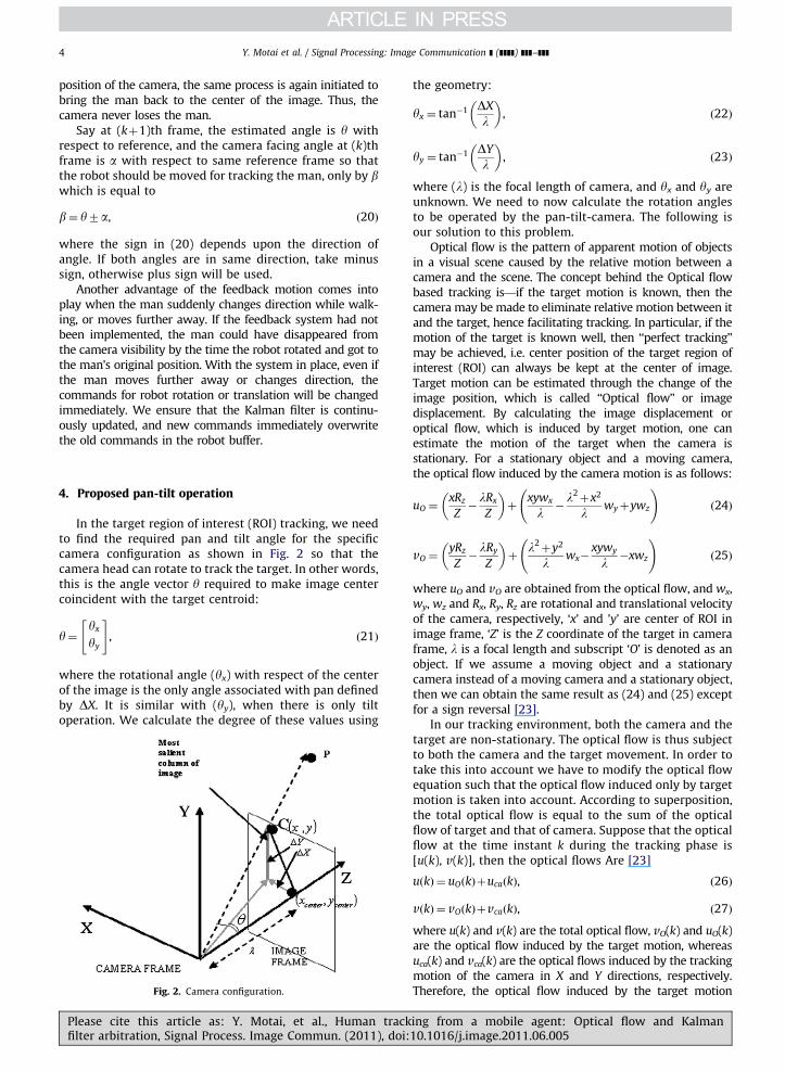
In the target region of interest (ROI) tracking, we needto find the required pan and tilt angle for the specificcamera configuration as shown in Fig. 2 so that thecamera head can rotate to track the target. In other words,this is the angle vector y required to make image centercoincident with the target centroid:
y¼yx
yy
" #, ð21Þ
where the rotational angle (yx) with respect of the centerof the image is the only angle associated with pan definedby DX. It is similar with (yy), when there is only tiltoperation. We calculate the degree of these values using
Fig. 2. Camera configuration.
Please cite this article as: Y. Motai, et al., Human trackfilter arbitration, Signal Process. Image Commun. (2011), doi:
the geometry:
yx ¼ tan�1 DX
l
� �, ð22Þ
yy ¼ tan�1 DY
l
� �, ð23Þ
where (l) is the focal length of camera, and yx and yy areunknown. We need to now calculate the rotation anglesto be operated by the pan-tilt-camera. The following isour solution to this problem.
Optical flow is the pattern of apparent motion of objectsin a visual scene caused by the relative motion between acamera and the scene. The concept behind the Optical flowbased tracking is—if the target motion is known, then thecamera may be made to eliminate relative motion between itand the target, hence facilitating tracking. In particular, if themotion of the target is known well, then ‘‘perfect tracking’’may be achieved, i.e. center position of the target region ofinterest (ROI) can always be kept at the center of image.Target motion can be estimated through the change of theimage position, which is called ‘‘Optical flow’’ or imagedisplacement. By calculating the image displacement oroptical flow, which is induced by target motion, one canestimate the motion of the target when the camera isstationary. For a stationary object and a moving camera,the optical flow induced by the camera motion is as follows:
uO ¼xRz
Z�lRx
Z
� �þ
xywx
l�l2þx2
lwyþywz
!ð24Þ
vO ¼yRz
Z�lRy
Z
� �þ
l2þy2
lwx�
xywy
l�xwz
!ð25Þ
where uO and vO are obtained from the optical flow, and wx,wy, wz and Rx, Ry, Rz are rotational and translational velocityof the camera, respectively, ‘x’ and ’y’ are center of ROI inimage frame, ‘Z’ is the Z coordinate of the target in cameraframe, l is a focal length and subscript ‘O’ is denoted as anobject. If we assume a moving object and a stationarycamera instead of a moving camera and a stationary object,then we can obtain the same result as (24) and (25) exceptfor a sign reversal [23].
In our tracking environment, both the camera and thetarget are non-stationary. The optical flow is thus subjectto both the camera and the target movement. In order totake this into account we have to modify the optical flowequation such that the optical flow induced only by targetmotion is taken into account. According to superposition,the total optical flow is equal to the sum of the opticalflow of target and that of camera. Suppose that the opticalflow at the time instant k during the tracking phase is[u(k), v(k)], then the optical flows Are [23]
uðkÞ ¼ uOðkÞþucaðkÞ, ð26Þ
vðkÞ ¼ vOðkÞþvcaðkÞ, ð27Þ
where u(k) and v(k) are the total optical flow, vO(k) and uO(k)are the optical flow induced by the target motion, whereasuca(k) and vca(k) are the optical flows induced by the trackingmotion of the camera in X and Y directions, respectively.Therefore, the optical flow induced by the target motion
ing from a mobile agent: Optical flow and Kalman10.1016/j.image.2011.06.005
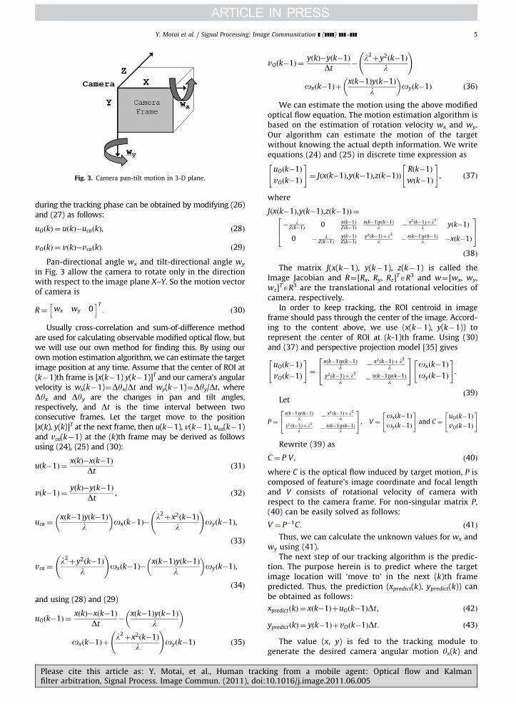
Fig. 3. Camera pan-tilt motion in 3-D plane.
Y. Motai et al. / Signal Processing: Image Communication ] (]]]]) ]]]–]]] 5
during the tracking phase can be obtained by modifying (26)and (27) as follows:
uOðkÞ ¼ uðkÞ�ucaðkÞ, ð28Þ
vOðkÞ ¼ vðkÞ�vcaðkÞ: ð29Þ
Pan-directional angle wx and tilt-directional angle wy
in Fig. 3 allow the camera to rotate only in the directionwith respect to the image plane X–Y. So the motion vectorof camera is
R¼ wx wy 0h iT
: ð30Þ
Usually cross-correlation and sum-of-difference methodare used for calculating observable modified optical flow, butwe will use our own method for finding this. By using ourown motion estimation algorithm, we can estimate the targetimage position at any time. Assume that the center of ROI at(k�1)th frame is [x(k�1) y(k�1)]T and our camera’s angularvelocity is wx(k�1)¼Dyx/Dt and wy(k�1)¼Dyy/Dt, whereDyx and Dyy are the changes in pan and tilt angles,respectively, and Dt is the time interval between twoconsecutive frames. Let the target move to the position[x(k), y(k)]T at the next frame, then u(k�1), v(k�1), uca(k�1)and vca(k�1) at the (k)th frame may be derived as followsusing (24), (25) and (30):
uðk�1Þ ¼xðkÞ�xðk�1Þ
Dtð31Þ
vðk�1Þ ¼yðkÞ�yðk�1Þ
Dt, ð32Þ
uca ¼xðk�1Þyðk�1Þ
l
� �oxðk�1Þ�
l2þx2ðk�1Þ
l
!oyðk�1Þ,
ð33Þ
vca ¼l2þy2ðk�1Þ
l
!oxðk�1Þ�
xðk�1Þyðk�1Þ
l
� �oyðk�1Þ,
ð34Þ
and using (28) and (29)
uOðk�1Þ ¼xðkÞ�xðk�1Þ
Dt�
xðk�1Þyðk�1Þ
l
� �
oxðk�1Þþl2þx2ðk�1Þ
l
!oyðk�1Þ ð35Þ
Please cite this article as: Y. Motai, et al., Human trackfilter arbitration, Signal Process. Image Commun. (2011), doi:
vOðk�1Þ ¼yðkÞ�yðk�1Þ
Dt�
l2þy2ðk�1Þ
l
!
oxðk�1Þþxðk�1Þyðk�1Þ
l
� �oyðk�1Þ ð36Þ
We can estimate the motion using the above modifiedoptical flow equation. The motion estimation algorithm isbased on the estimation of rotation velocity wx and wy.Our algorithm can estimate the motion of the targetwithout knowing the actual depth information. We writeequations (24) and (25) in discrete time expression as
uOðk�1Þ
vOðk�1Þ
" #¼ Jðxðk�1Þ,yðk�1Þ,zðk�1ÞÞ
Rðk�1Þ
wðk�1Þ
" #, ð37Þ
where
Jðxðk�1Þ,yðk�1Þ,zðk�1ÞÞ ¼
� lZðk�1Þ 0 xðk�1Þ
Zðk�1Þxðk�1Þyðk�1Þ
l �x2ðk�1Þþl2
l yðk�1Þ
0 � lZðk�1Þ
yðk�1ÞZðk�1Þ
y2ðk�1Þþl2
l �xðk�1Þyðk�1Þ
l �xðk�1Þ
264
375
ð38Þ
The matrix J(x(k�1), y(k�1), z(k�1) is called theImage Jacobian and R¼[Rx, Ry, Rz]
TAR3 and w¼[wx, wy,wz]
TAR3 are the translational and rotational velocities ofcamera, respectively.
In order to keep tracking, the ROI centroid in imageframe should pass through the center of the image. Accord-ing to the content above, we use (x(k�1), y(k�1)) torepresent the center of ROI at (k-1)th frame. Using (30)and (37) and perspective projection model [35] gives
uOðk�1Þ
vOðk�1Þ
" #¼
xðk�1Þyðk�1Þl �
x2ðk�1Þþl2
ly2ðk�1Þþl2
l �xðk�1Þyðk�1Þ
l
24
35 oxðk�1Þ
oyðk�1Þ
" #:
ð39ÞLet2 3
P¼
xðk�1Þyðk�1Þl �
x2ðk�1Þþl2
ly2ðk�1Þþl2
l �xðk�1Þyðk�1Þ
l
4 5, V ¼oxðk�1Þ
oyðk�1Þ
" #and C ¼
uOðk�1Þ
vOðk�1Þ
" #
Rewrite (39) as
C ¼ P V , ð40Þ
where C is the optical flow induced by target motion, P iscomposed of feature’s image coordinate and focal lengthand V consists of rotational velocity of camera withrespect to the camera frame. For non-singular matrix P,(40) can be easily solved as follows:
V ¼ P�1C: ð41Þ
Thus, we can calculate the unknown values for wx andwy using (41).
The next step of our tracking algorithm is the predic-tion. The purpose herein is to predict where the targetimage location will ‘move to’ in the next (k)th framepredicted. Thus, the prediction (xpredict(k), ypredict(k)) canbe obtained as follows:
xpredictðkÞ ¼ xðk�1ÞþuOðk�1ÞDt, ð42Þ
ypredictðkÞ ¼ yðk�1ÞþvOðk�1ÞDt: ð43Þ
The value (x, y) is fed to the tracking module togenerate the desired camera angular motion yx(k) and
ing from a mobile agent: Optical flow and Kalman10.1016/j.image.2011.06.005
Raytheon Infrared Camera @15Hz,Image size 640×480pixel
SICK Laser Range Finder
PC
Mobile Robot
Fig. 6. Pioneer mobile robot platform.
Y. Motai et al. / Signal Processing: Image Communication ] (]]]]) ]]]–]]]6
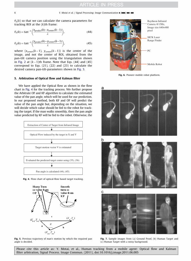
yy(k) so that we can calculate the camera parameters fortracking ROI at the (k)th frame:
yxðkÞ ¼ tan�1 xpredictðkÞ�xcenterðk�1Þ
l
� �, ð44Þ
yyðkÞ ¼ tan�1 ypredictðkÞ�ycenterðk�1Þ
l
� �, ð45Þ
where (xcenter(k�1), ycenter(k�1)) is the center of theimage, and not the center of ROI, obtained from thepan-tilt camera position using the triangulation shownin Fig. 2 at (k�1)th frame. Note that Eqs. (44) and (45)correspond to Eqs. (21), (22) and (23) to calculate thedesired camera pan-tilt-parameters shown in Fig. 3.
5. Arbitration of Optical flow and Kalman filter
We have applied the Optical flow as shown in the flowchart in Fig. 4 for the tracking process. We further proposethe Arbitrate OF and KF algorithm to calculate the estimatedvalue of the pan angle, which will be used for our prediction.In our proposed method, both KF and OF will predict thevalue of the pan angle but, depending on the situation, wewill decide which value should be fed to the robot for track-ing the target. If the man walks smoothly, then the pan anglevalue predicted by KF will be fed to the robot. Otherwise, the
Extraction of Center of Target from Infrared Image
Optical Flow induced by the target in X and Y
Target motion vector V is estimated
Pan angle is calculated (44), (45).
Evaluated the predicted target center using (35), (36).
Fig. 4. Flow chart of optical-flow based target tracking.
Fig. 5. Previous trajectory of man’s motion by which the required pan
angle is decided.
Fig. 7. Sample images from (a) Ground Proof, (b) Human Target and
(c) Human Target with a noisy background.
Please cite this article as: Y. Motai, et al., Human tracking from a mobile agent: Optical flow and Kalmanfilter arbitration, Signal Process. Image Commun. (2011), doi:10.1016/j.image.2011.06.005
Y. Motai et al. / Signal Processing: Image Communication ] (]]]]) ]]]–]]] 7
pan angle value predicted by OF will be fed to the robot. Theproposed algorithm for arbitration is as follows:
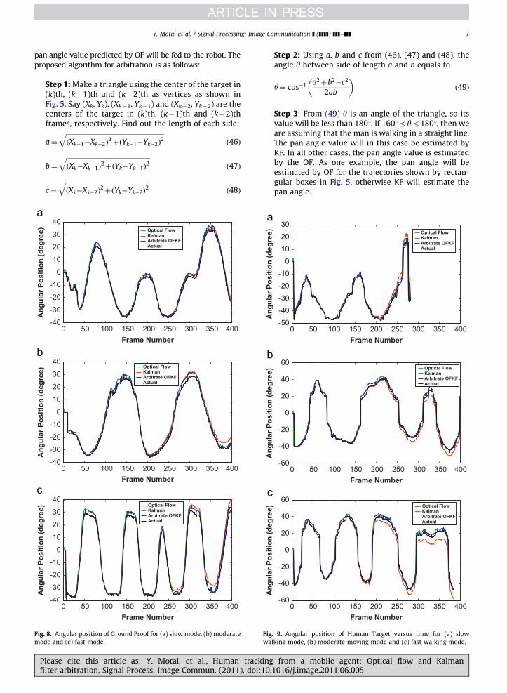
Step 1: Make a triangle using the center of the target in(k)th, (k�1)th and (k�2)th as vertices as shown inFig. 5. Say (Xk, Yk), (Xk�1, Yk�1) and (Xk�2, Yk�2) are thecenters of the target in (k)th, (k�1)th and (k�2)thframes, respectively. Find out the length of each side:
a¼
ffiffiffiffiffiffiffiffiffiffiffiffiffiffiffiffiffiffiffiffiffiffiffiffiffiffiffiffiffiffiffiffiffiffiffiffiffiffiffiffiffiffiffiffiffiffiffiffiffiffiffiffiffiffiffiffiffiffiffiffiffiðXk�1�Xk�2Þ
2þðYk�1�Yk�2Þ
2q
ð46Þ
b¼
ffiffiffiffiffiffiffiffiffiffiffiffiffiffiffiffiffiffiffiffiffiffiffiffiffiffiffiffiffiffiffiffiffiffiffiffiffiffiffiffiffiffiffiffiffiffiffiffiffiffiffiffiðXk�Xk�1Þ
2þðYk�Yk�1Þ
2q
ð47Þ
c¼
ffiffiffiffiffiffiffiffiffiffiffiffiffiffiffiffiffiffiffiffiffiffiffiffiffiffiffiffiffiffiffiffiffiffiffiffiffiffiffiffiffiffiffiffiffiffiffiffiffiffiffiffiðXk�Xk�2Þ
2þðYk�Yk�2Þ
2q
ð48Þ
0 50 100 150 200 250 300 350 400-40
-30
-20
-10
0
10
20
30
40
Frame Number
Ang
ular
Pos
ition
(deg
ree) Optical Flow
KalmanArbitrate OFKFActual
0 50 100 150 200 250 300 350 400-40
-30
-20
-10
0
10
20
30
40
Frame Number
Ang
ular
Pos
ition
(deg
ree)
0 50 100 150 200 250 300 350 400-40
-30
-20
-10
0
10
20
30
40
Frame Number
Ang
ular
Pos
ition
(deg
ree)
Optical FlowKalmanArbitrate OFKFActual
Optical FlowKalmanArbitrate OFKFActual
Fig. 8. Angular position of Ground Proof for (a) slow mode, (b) moderate
mode and (c) fast mode.
Figwa
Please cite this article as: Y. Motai, et al., Human trackingfilter arbitration, Signal Process. Image Commun. (2011), doi:10.
Step 2: Using a, b and c from (46), (47) and (48), theangle y between side of length a and b equals to
y¼ cos�1 a2þb2�c2
2ab
� �ð49Þ
Step 3: From (49) y is an angle of the triangle, so itsvalue will be less than 1801. If 1601ryr1801, then weare assuming that the man is walking in a straight line.The pan angle value will in this case be estimated byKF. In all other cases, the pan angle value is estimatedby the OF. As one example, the pan angle will beestimated by OF for the trajectories shown by rectan-gular boxes in Fig. 5, otherwise KF will estimate thepan angle.
0 50 100 150 200 250 300 350 400-50
-40
-30
-20
-10
0
10
20
30
Frame Number
Ang
ular
Pos
ition
(deg
ree) Optical Flow
KalmanArbitrate OFKFActual
0 50 100 150 200 250 300 350 400-60
-40
-20
0
20
40
60
Frame Number
Ang
ular
Pos
ition
(deg
ree) Optical Flow
KalmanArbitrate OFKFActual
0 50 100 150 200 250 300 350 400-60
-40
-20
0
20
40
60
Frame Number
Ang
ular
Pos
ition
(deg
ree) Optical Flow
KalmanArbitrate OFKFActual
. 9. Angular position of Human Target versus time for (a) slow
lking mode, (b) moderate moving mode and (c) fast walking mode.
from a mobile agent: Optical flow and Kalman1016/j.image.2011.06.005
Y. Motai et al. / Signal Processing: Image Communication ] (]]]]) ]]]–]]]8
6. Experimental results
This section compares the results obtained from algo-rithms using only KF, only OF, and finally the ArbitrateOFKF model developed in this paper. Since we have trackeda single point in the KF, we have used only one featurepoint in the OF for comparisons. A final comparison is madebetween Arbitrate OFKF and the particle filter at the end of
0 50 100 150 2-40
-20
0
20
40
60
Frame
Ang
ular
Pos
ition
(deg
ree)
0 50 100 150 2-30
-20
-10
0
10
20
30
40
50
Frame
Ang
ular
Pos
ition
(deg
ree)
0 50 100 150 2-30
-20
-10
0
10
20
30
40
50
Frame
Ang
ular
Pos
ition
(deg
ree)
Optical FlowKalmanArbitrate OFKFActual
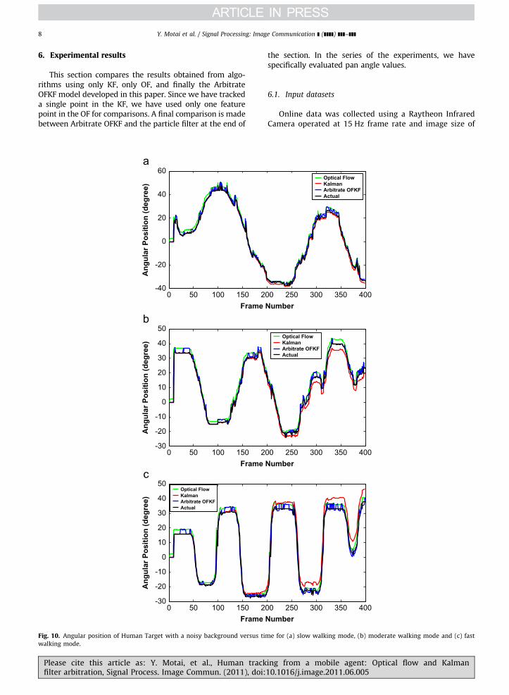
Fig. 10. Angular position of Human Target with a noisy background versus ti
walking mode.
Please cite this article as: Y. Motai, et al., Human trackfilter arbitration, Signal Process. Image Commun. (2011), doi:
the section. In the series of the experiments, we havespecifically evaluated pan angle values.
6.1. Input datasets
Online data was collected using a Raytheon InfraredCamera operated at 15 Hz frame rate and image size of
00 250 300 350 400Number
Optical FlowKalmanArbitrate OFKFActual
00 250 300 350 400Number
00 250 300 350 400Number
Optical FlowKalmanArbitrate OFKFActual
me for (a) slow walking mode, (b) moderate walking mode and (c) fast
ing from a mobile agent: Optical flow and Kalman10.1016/j.image.2011.06.005
Y. Motai et al. / Signal Processing: Image Communication ] (]]]]) ]]]–]]] 9
640�480 pixels. The data collection procedure consistedof a target moving in front of an infrared camera, whichwas mounted on the Active Media robot shown in Fig. 6.Data was collected for the three modes of walking: slow,moderate and fast. In slow walking mode, the targetmoved slowly in front of the camera without taking anysudden turns. In the moderate walking mode, the targetmoved with moderate speed in front of the camera takingsmooth turns. In the fast walking mode, the target movedwith high velocity taking sudden turns during the courseof its motion.
Fig. 7a–c is collections of images that show the varioustarget types during their motion. Each of these images is30 frames apart in the time reference. The white line, asshown in Fig. 7, is the most salient image column, whichis our measured tracking location through our algorithms.Instead of showing specific Human Target trackingresults, we have evaluated three different target cases.Fig. 7a is a ground proof experiment, which involves asimple target in a noiseless background, Fig. 7b involves ahuman target walking in a low noise environment andFig. 7c shows a human target walking in a very noisyenvironment. The ground proof was examined using a
250300350-50
0
50
Y coor
Pan
Ang
le (d
egre
es)
Optical FlowKalmanArbitrate OFKFActual
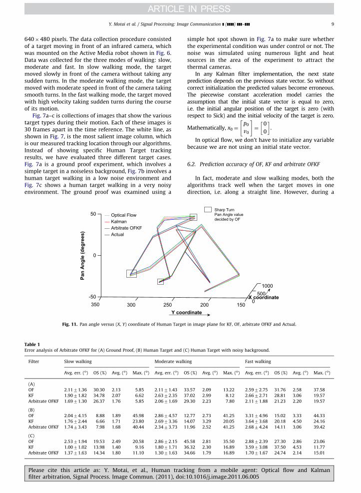
Fig. 11. Pan angle versus (X, Y) coordinate of Human Target
Table 1Error analysis of Arbitrate OFKF for (A) Ground Proof, (B) Human Target and (C
Filter Slow walking Moderate walk
Avg. err. (o) OS (%) Avg. (o) Max. (o) Avg. err. (o) O
(A)
OF 2.1171.36 30.30 2.13 5.85 2.1171.43 3
KF 1.9071.82 34.78 2.07 6.62 2.6372.35 3
Arbitrate OFKF 1.6971.30 26.37 1.76 5.85 2.0671.69 2
(B)
OF 2.0474.15 8.88 1.89 45.98 2.8674.57 1
KF 1.7672.44 6.66 1.71 23.80 2.6973.36 1
Arbitrate OFKF 1.7473.43 7.98 1.68 40.44 2.3473.73 1
(C)
OF 2.5371.94 19.53 2.49 20.58 2.8672.15 4
KF 1.0071.02 13.98 1.40 9.16 1.8071.71 3
Arbitrate OFKF 1.3771.63 14.34 1.80 11.10 1.3071.63 3
Please cite this article as: Y. Motai, et al., Human trackfilter arbitration, Signal Process. Image Commun. (2011), doi:
simple hot spot shown in Fig. 7a to make sure whetherthe experimental condition was under control or not. Thenoise was simulated using numerous light and heatsources in the area of the experiment to attract thethermal cameras.
In any Kalman filter implementation, the next stateprediction depends on the previous state vector. So withoutcorrect initialization the predicted values become erroneous.The piecewise constant acceleration model carries theassumption that the initial state vector is equal to zero,i.e. the initial angular position of the target is zero (withrespect to Sick) and the initial velocity of the target is zero.
Mathematically, x0 ¼p0
v0
" #¼
0
0
� �.
In optical flow, we don’t have to initialize any variablebecause we are not using an initial state vector.
6.2. Prediction accuracy of OF, KF and arbitrate OFKF
In fact, moderate and slow walking modes, both thealgorithms track well when the target moves in onedirection, i.e. along a straight line. However, during a
0500
1000
150200X coordinate
dinate
Sharp TurnPan Angle valuedecided by OF
in image plane for KF, OF, arbitrate OFKF and Actual.
) Human Target with noisy background.
ing Fast walking
S (%) Avg. (o) Max. (o) Avg. err. (o) OS (%) Avg. (o) Max. (o)
3.57 2.09 13.22 2.5972.75 31.76 2.58 37.58
7.02 2.99 8.12 2.6672.71 28.81 3.06 19.57
9.30 2.23 7.80 2.1171.88 21.23 2.20 19.57
2.77 2.73 41.25 3.3174.96 15.02 3.33 44.33
4.07 3.29 20.05 3.6473.68 20.18 4.50 24.16
1.96 2.52 41.25 2.6874.24 14.11 3.06 39.42
5.58 2.81 35.50 2.8872.39 27.30 2.86 23.06
6.32 2.30 16.89 3.5973.08 37.50 4.53 11.77
4.66 1.79 16.89 1.7071.67 24.74 2.14 15.01
ing from a mobile agent: Optical flow and Kalman10.1016/j.image.2011.06.005
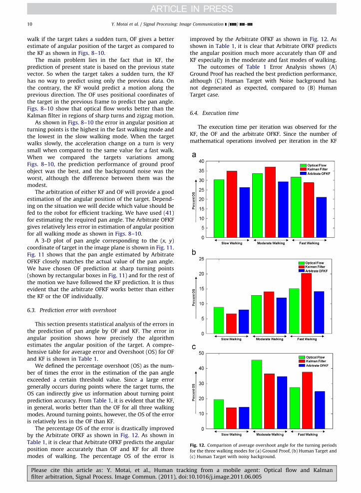
Fig. 12. Comparison of average overshoot angle for the turning periods
for the three walking modes for (a) Ground Proof, (b) Human Target and
(c) Human Target with noisy background.
Y. Motai et al. / Signal Processing: Image Communication ] (]]]]) ]]]–]]]10
walk if the target takes a sudden turn, OF gives a betterestimate of angular position of the target as compared tothe KF as shown in Figs. 8–10.
The main problem lies in the fact that in KF, theprediction of present state is based on the previous statevector. So when the target takes a sudden turn, the KFhas no way to predict using only the previous data. Onthe contrary, the KF would predict a motion along theprevious direction. The OF uses positional coordinates ofthe target in the previous frame to predict the pan angle.Figs. 8–10 show that optical flow works better than theKalman filter in regions of sharp turns and zigzag motion.
As shown in Figs. 8–10 the error in angular position atturning points is the highest in the fast walking mode andthe lowest in the slow walking mode. When the targetwalks slowly, the acceleration change on a turn is verysmall when compared to the same value for a fast walk.When we compared the targets variations amongFigs. 8–10, the prediction performance of ground proofobject was the best, and the background noise was theworst, although the difference between them was themodest.
The arbitration of either KF and OF will provide a goodestimation of the angular position of the target. Depend-ing on the situation we will decide which value should befed to the robot for efficient tracking. We have used (41)for estimating the required pan angle. The Arbitrate OFKFgives relatively less error in estimation of angular positionfor all walking mode as shown in Figs. 8–10.
A 3-D plot of pan angle corresponding to the (x, y)coordinate of target in the image plane is shown in Fig. 11.Fig. 11 shows that the pan angle estimated by ArbitrateOFKF closely matches the actual value of the pan angle.We have chosen OF prediction at sharp turning points(shown by rectangular boxes in Fig. 11) and for the rest ofthe motion we have followed the KF prediction. It is thusevident that the arbitrate OFKF works better than eitherthe KF or the OF individually.
6.3. Prediction error with overshoot
This section presents statistical analysis of the errors inthe prediction of pan angle by OF and KF. The error inangular position shows how precisely the algorithmestimates the angular position of the target. A compre-hensive table for average error and Overshoot (OS) for OFand KF is shown in Table 1.
We defined the percentage overshoot (OS) as the num-ber of times the error in the estimation of the pan angleexceeded a certain threshold value. Since a large errorgenerally occurs during points where the target turns, theOS can indirectly give us information about turning pointprediction accuracy. From Table 1, it is evident that the KF,in general, works better than the OF for all three walkingmodes. Around turning points, however, the OS of the erroris relatively less in the OF than KF.
The percentage OS of the error is drastically improvedby the Arbitrate OFKF as shown in Fig. 12. As shown inTable 1, it is clear that Arbitrate OFKF predicts the angularposition more accurately than OF and KF for all threemodes of walking. The percentage OS of the error is
Please cite this article as: Y. Motai, et al., Human trackfilter arbitration, Signal Process. Image Commun. (2011), doi:
improved by the Arbitrate OFKF as shown in Fig. 12. Asshown in Table 1, it is clear that Arbitrate OFKF predictsthe angular position much more accurately than OF andKF especially in the moderate and fast modes of walking.
The outcomes of Table 1 Error Analysis shows (A)Ground Proof has reached the best prediction performance,although (C) Human Target with Noise background hasnot degenerated as expected, compared to (B) HumanTarget case.
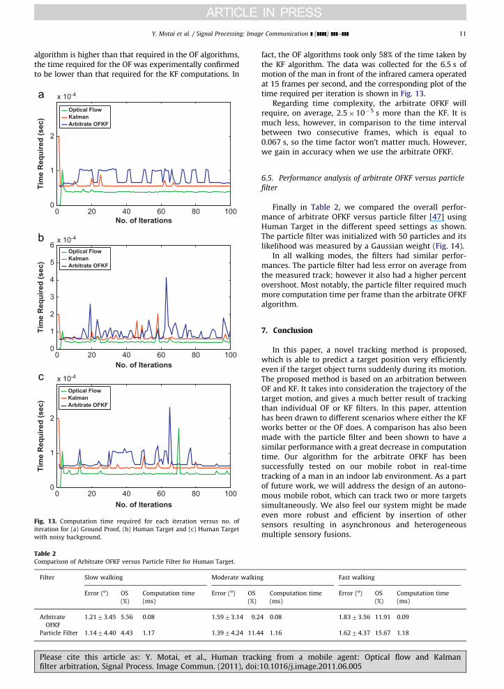
6.4. Execution time
The execution time per iteration was observed for theKF, the OF and the arbitrate OFKF. Since the number ofmathematical operations involved per iteration in the KF
ing from a mobile agent: Optical flow and Kalman10.1016/j.image.2011.06.005
Y. Motai et al. / Signal Processing: Image Communication ] (]]]]) ]]]–]]] 11
algorithm is higher than that required in the OF algorithms,the time required for the OF was experimentally confirmedto be lower than that required for the KF computations. In
0 20 40 60 80 1000
1
2
x 10-4
No. of Iterations
Tim
e R
equi
red
(sec
)
Optical FlowKalmanArbitrate OFKF
0 20 40 60 80 1000
1
2
3
4
5
6x 10⁻⁴
No. of Iterations
Tim
e R
equi
red
(sec
)
0 20 40 60 80 1000
1
2
x 10-4
No. of Iterations
Tim
e R
equi
red
(sec
)
Optical FlowKalmanArbitrate OFKF
Optical FlowKalmanArbitrate OFKF
Fig. 13. Computation time required for each iteration versus no. of
iteration for (a) Ground Proof, (b) Human Target and (c) Human Target
with noisy background.
Table 2Comparison of Arbitrate OFKF versus Particle Filter for Human Target.
Filter Slow walking Moderate walkin
Error (o) OS
(%)
Computation time
(ms)
Error (o) OS
(%)
Arbitrate
OFKF
1.2173.45 5.56 0.08 1.5973.14 9.2
Particle Filter 1.1474.40 4.43 1.17 1.3974.24 11.4
Please cite this article as: Y. Motai, et al., Human trackfilter arbitration, Signal Process. Image Commun. (2011), doi:
fact, the OF algorithms took only 58% of the time taken bythe KF algorithm. The data was collected for the 6.5 s ofmotion of the man in front of the infrared camera operatedat 15 frames per second, and the corresponding plot of thetime required per iteration is shown in Fig. 13.
Regarding time complexity, the arbitrate OFKF willrequire, on average, 2.5�10�5 s more than the KF. It ismuch less, however, in comparison to the time intervalbetween two consecutive frames, which is equal to0.067 s, so the time factor won’t matter much. However,we gain in accuracy when we use the arbitrate OFKF.
6.5. Performance analysis of arbitrate OFKF versus particle
filter
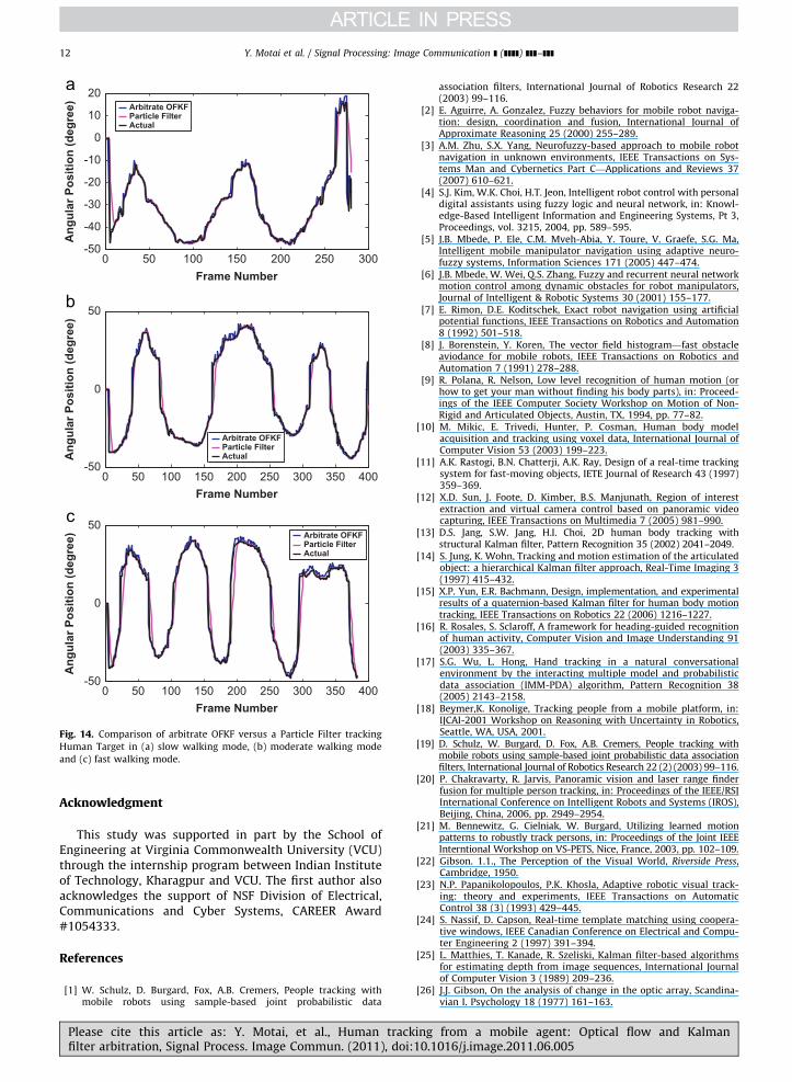
Finally in Table 2, we compared the overall perfor-mance of arbitrate OFKF versus particle filter [47] usingHuman Target in the different speed settings as shown.The particle filter was initialized with 50 particles and itslikelihood was measured by a Gaussian weight (Fig. 14).
In all walking modes, the filters had similar perfor-mances. The particle filter had less error on average fromthe measured track; however it also had a higher percentovershoot. Most notably, the particle filter required muchmore computation time per frame than the arbitrate OFKFalgorithm.
7. Conclusion
In this paper, a novel tracking method is proposed,which is able to predict a target position very efficientlyeven if the target object turns suddenly during its motion.The proposed method is based on an arbitration betweenOF and KF. It takes into consideration the trajectory of thetarget motion, and gives a much better result of trackingthan individual OF or KF filters. In this paper, attentionhas been drawn to different scenarios where either the KFworks better or the OF does. A comparison has also beenmade with the particle filter and been shown to have asimilar performance with a great decrease in computationtime. Our algorithm for the arbitrate OFKF has beensuccessfully tested on our mobile robot in real-timetracking of a man in an indoor lab environment. As a partof future work, we will address the design of an autono-mous mobile robot, which can track two or more targetssimultaneously. We also feel our system might be madeeven more robust and efficient by insertion of othersensors resulting in asynchronous and heterogeneousmultiple sensory fusions.
g Fast walking
Computation time
(ms)
Error (o) OS
(%)
Computation time
(ms)
4 0.08 1.8373.56 11.91 0.09
4 1.16 1.6274.37 15.67 1.18
ing from a mobile agent: Optical flow and Kalman10.1016/j.image.2011.06.005
0 50 100 150 200 250 300-50
-40
-30
-20
-10
0
10
20
Frame Number
Ang
ular
Pos
ition
(deg
ree) Arbitrate OFKF
Particle FilterActual
Arbitrate OFKFParticle FilterActual
Arbitrate OFKFParticle FilterActual
0 50 100 150 200 250 300 350 400-50
0
50
Frame Number
Ang
ular
Pos
ition
(deg
ree)
0 50 100 150 200 250 300 350 400-50
0
50
Frame Number
Ang
ular
Pos
ition
(deg
ree)
Fig. 14. Comparison of arbitrate OFKF versus a Particle Filter tracking
Human Target in (a) slow walking mode, (b) moderate walking mode
and (c) fast walking mode.
Y. Motai et al. / Signal Processing: Image Communication ] (]]]]) ]]]–]]]12
Acknowledgment
This study was supported in part by the School ofEngineering at Virginia Commonwealth University (VCU)through the internship program between Indian Instituteof Technology, Kharagpur and VCU. The first author alsoacknowledges the support of NSF Division of Electrical,Communications and Cyber Systems, CAREER Award#1054333.
References
[1] W. Schulz, D. Burgard, Fox, A.B. Cremers, People tracking withmobile robots using sample-based joint probabilistic data
Please cite this article as: Y. Motai, et al., Human trackfilter arbitration, Signal Process. Image Commun. (2011), doi:
association filters, International Journal of Robotics Research 22(2003) 99–116.
[2] E. Aguirre, A. Gonzalez, Fuzzy behaviors for mobile robot naviga-tion: design, coordination and fusion, International Journal ofApproximate Reasoning 25 (2000) 255–289.
[3] A.M. Zhu, S.X. Yang, Neurofuzzy-based approach to mobile robotnavigation in unknown environments, IEEE Transactions on Sys-tems Man and Cybernetics Part C—Applications and Reviews 37(2007) 610–621.
[4] S.J. Kim, W.K. Choi, H.T. Jeon, Intelligent robot control with personaldigital assistants using fuzzy logic and neural network, in: Knowl-edge-Based Intelligent Information and Engineering Systems, Pt 3,Proceedings, vol. 3215, 2004, pp. 589–595.
[5] J.B. Mbede, P. Ele, C.M. Mveh-Abia, Y. Toure, V. Graefe, S.G. Ma,Intelligent mobile manipulator navigation using adaptive neuro-fuzzy systems, Information Sciences 171 (2005) 447–474.
[6] J.B. Mbede, W. Wei, Q.S. Zhang, Fuzzy and recurrent neural networkmotion control among dynamic obstacles for robot manipulators,Journal of Intelligent & Robotic Systems 30 (2001) 155–177.
[7] E. Rimon, D.E. Koditschek, Exact robot navigation using artificialpotential functions, IEEE Transactions on Robotics and Automation8 (1992) 501–518.
[8] J. Borenstein, Y. Koren, The vector field histogram—fast obstacleaviodance for mobile robots, IEEE Transactions on Robotics andAutomation 7 (1991) 278–288.
[9] R. Polana, R. Nelson, Low level recognition of human motion (orhow to get your man without finding his body parts), in: Proceed-ings of the IEEE Computer Society Workshop on Motion of Non-Rigid and Articulated Objects, Austin, TX, 1994, pp. 77–82.
[10] M. Mikic, E. Trivedi, Hunter, P. Cosman, Human body modelacquisition and tracking using voxel data, International Journal ofComputer Vision 53 (2003) 199–223.
[11] A.K. Rastogi, B.N. Chatterji, A.K. Ray, Design of a real-time trackingsystem for fast-moving objects, IETE Journal of Research 43 (1997)359–369.
[12] X.D. Sun, J. Foote, D. Kimber, B.S. Manjunath, Region of interestextraction and virtual camera control based on panoramic videocapturing, IEEE Transactions on Multimedia 7 (2005) 981–990.
[13] D.S. Jang, S.W. Jang, H.I. Choi, 2D human body tracking withstructural Kalman filter, Pattern Recognition 35 (2002) 2041–2049.
[14] S. Jung, K. Wohn, Tracking and motion estimation of the articulatedobject: a hierarchical Kalman filter approach, Real-Time Imaging 3(1997) 415–432.
[15] X.P. Yun, E.R. Bachmann, Design, implementation, and experimentalresults of a quaternion-based Kalman filter for human body motiontracking, IEEE Transactions on Robotics 22 (2006) 1216–1227.
[16] R. Rosales, S. Sclaroff, A framework for heading-guided recognitionof human activity, Computer Vision and Image Understanding 91(2003) 335–367.
[17] S.G. Wu, L. Hong, Hand tracking in a natural conversationalenvironment by the interacting multiple model and probabilisticdata association (IMM-PDA) algorithm, Pattern Recognition 38(2005) 2143–2158.
[18] Beymer,K. Konolige, Tracking people from a mobile platform, in:IJCAI-2001 Workshop on Reasoning with Uncertainty in Robotics,Seattle, WA, USA, 2001.
[19] D. Schulz, W. Burgard, D. Fox, A.B. Cremers, People tracking withmobile robots using sample-based joint probabilistic data associationfilters, International Journal of Robotics Research 22 (2) (2003) 99–116.
[20] P. Chakravarty, R. Jarvis, Panoramic vision and laser range finderfusion for multiple person tracking, in: Proceedings of the IEEE/RSJInternational Conference on Intelligent Robots and Systems (IROS),Beijing, China, 2006, pp. 2949–2954.
[21] M. Bennewitz, G. Cielniak, W. Burgard, Utilizing learned motionpatterns to robustly track persons, in: Proceedings of the Joint IEEEInterntional Workshop on VS-PETS, Nice, France, 2003, pp. 102–109.
[22] Gibson. 1.1., The Perception of the Visual World, Riverside Press,Cambridge, 1950.
[23] N.P. Papanikolopoulos, P.K. Khosla, Adaptive robotic visual track-ing: theory and experiments, IEEE Transactions on AutomaticControl 38 (3) (1993) 429–445.
[24] S. Nassif, D. Capson, Real-time template matching using coopera-tive windows, IEEE Canadian Conference on Electrical and Compu-ter Engineering 2 (1997) 391–394.
[25] L. Matthies, T. Kanade, R. Szeliski, Kalman filter-based algorithmsfor estimating depth from image sequences, International Journalof Computer Vision 3 (1989) 209–236.
[26] J.J. Gibson, On the analysis of change in the optic array, Scandina-vian I. Psychology 18 (1977) 161–163.
ing from a mobile agent: Optical flow and Kalman10.1016/j.image.2011.06.005
Y. Motai et al. / Signal Processing: Image Communication ] (]]]]) ]]]–]]] 13
[27] J. Schilling Robert, Fundamentals of Robotics Analysis and Control,in: B. Horn, B. Schunck (Eds.), ‘‘Determining Optical Flow’’. Artificial
Intelligence, vol. 17, Prentice-Hall, Englewood Cliffs, N.J., 1990,pp. 185–203in: B. Horn, B. Schunck (Eds.), ‘‘Determining OpticalFlow’’. Artificial Intelligence, vol. 17, Prentice-Hall, Englewood Cliffs,
N.J., 1981, pp. 185–203.[28] B. Horn, B. Schunck, Determining optical flow, Artificial Intelligence
17 (1981) 185–203.[29] N. Sawasaki, T. Morita, T. Uchiyama, Design and implementation of
high-speed visual tracking systems for real-time motion analysis,IEEE International Conference on Pattern Recognition 3 (1996)
478–483.[30] Kazutoshi Koga, Hidetoshi Miike, Determining optical flow from
sequential images, Systems and Computers in Japan 19 (8) (1988)77–86.
[31] G.D. Hager, P.N. Belhumeur, efficient region tracking with para-metric models of geometry and illumination, IEEE Transactions onPattern Analysis and Machine Intelligence 20 (10) (1998)
1025–1039.[32] A. Blake, R. Curwen, A. Zisserman, A framework for spatiotemporal
control in the tracking of visual contours, International Journal ofComputer Vision 11 (2) (1993) 127–145.
[33] J.S. Park, J.H. Han, Contour matching: a curvature-based approach,Image and Vision Computing 16 (1998) 181–189.
[34] W.G. Yau, Design and implementation of visual servoing system forrealistic air target tracking, Master’s thesis, Dept. Elec. Eng.,National Taiwan University, 2000.
[35] J. Mataric Maja, The Robotics Primer, MIT Press, Cambridge, 2007,p. 300.
[36] H.A. Rowley, S. Baluja, T. Kanade, Neural network-based facedetection, IEEE Transactions on Pattern Analysis and Machine
Intelligence 20 (1998) 23–38.[37] P. Liberatore, M. Schaerf, Arbitration (or how to merge knowledge
bases), IEEE Transactions on Knowledge and Data Engineering 10(1998) 76–90.
Please cite this article as: Y. Motai, et al., Human trackfilter arbitration, Signal Process. Image Commun. (2011), doi:
[38] R.O. Atienza, M.H. Ang, A flexible control architecture for mobilerobots: an application for a walking robot, Journal of Intelligent &Robotic Systems 30 (2001) 29–48.
[39] K. Jung, Neural network-based text location in color images,Pattern Recognition Letters 22 (2001) 1503–1515.
[40] T. Kampke, Functional arbitration for multipurpose senso-motorysystems, Robotics and Autonomous Systems 27 (1999) 129–150.
[41] M. Kam, X.X. Zhu, P. Kalata, Sensor fusion for mobile robotnavigation, Proceedings of the IEEE 85 (1997) 108–119.
[42] R.T. Pack, D. Mitchell Wilkes, K. Kawamura, A software architecturefor integrated service robot development, in: Proceedings of theIEEE International Conference on Systems, Man, and Cybernetics,vol. 4, 1997, pp. 3774–3779.
[43] H. Himberg, Y. Motai, Head orientation prediction: delta quaternionversus quaternion, IEEE Transactions on Systems, Man and Cyber-netics. Part B: Cybernetics 39 (6) (2009) 1382–1392.
[44] H. Himberg, Y. Motai, C. Barrios, R-Adaptive Kalman filteringapproach to estimate head orientation for driving simulator,Proceedings of International IEEE Conference on Intelligent Trans-portation Systems (2006) 851–857.
[45] C. Barrios, H. Himberg, Y. Motai, A. Sadek, Multiple model frame-work of adaptive extended Kalman filtering for predicting vehiclelocation, Proceedings of International IEEE Conference on Intelli-gent Transportation Systems (2006) 1053–1059.
[46] F. Tafazzoli, R. Safabakhsh, Model-based human gait recognitionusing leg and arm movements, Engineering Applications of Artifi-cial Intelligence 23 (2006) 1237–1246.
[47] M. Isard, A. Blake, CONDENSATION—conditional density propaga-tion for visual tracking, International Journal of Computer Vision 29(1) (1998) 5–28.
[48] A. Doulamis, N. Matsatsinis, Visual understanding industrial work-flows under uncertainty on distributed service oriented architec-tures, Future Generation Computer Systems, in press.
[49] Y. Motai, Visual-based human–robotic interaction for extractingsalient features of an industrial object for an automated assemblysystem, Special Issue on Machine Vision, International Journal ofComputers in Industry 56 (8–9) (2005) 943–957.
ing from a mobile agent: Optical flow and Kalman10.1016/j.image.2011.06.005