HP-405C-CR-Manual.pdf - The Hewlett Packard Archive
51
I. : HP Archive .. . This vintage Hewlett Packard document was preserved and distributed by www. hparchive.com ' Please visit us on the web ! .. On-line curator: Tony Gerbic
-
Upload
khangminh22 -
Category
Documents
-
view
0 -
download
0
Transcript of HP-405C-CR-Manual.pdf - The Hewlett Packard Archive

I . : HP Archive
.. .
This vintage Hewlett Packard document was preserved and distributed by
www. hparchive.com
' Please visit us on the web ! . .
On-line curator: Tony Gerbic
O P E R A T I N G A N D S E R V I C I N G M A N U A L
HP Part No. 405C-901
MODEL 405C/CR S E R I A L S PREFIXED: 243-, 402-
219-, 120-, 114-, 101-
DI AUTO
GITAL M V
A T I C DC OLTMET ER
1961 C o p v r i o h l HEWLETT-PACKARD C O M P A N Y 1501 P A G E MILL R O A D , P A L 0 ALTO, C A L I F O R N I A , U.S.A.
0051 8- 3 v Printed I U M E 1963

Table of Contents Lists of Illustrations and Tables
Model 405C
Section
TABLE OF CONTENTS
Page Section I GENERALDESCRIPTION . . . . . . . . . . 1'-1 III
1.1 . Identification . . . . . . . . . . . . . 1-1 1.2 . Cooling . . . . . . . . . . . . . . . . . 1-1 1.3 . Stepping Switch . . . . . . . . . . . . 1-1
1.5 . Three Conductor Power Cable . . . . 1-1 1.4 . Power Line Voltage . . . . . . . . . . 1-1 Iv
II OPERATING INSTRUCTIONS . . . . . . . . 2-1 2.1 . Automatic Operation . . . . . . . . . 2-1 2.2 . Manual Operation . . . . . . . . . . . 2-1 2.3 . Calibration . . . . . . . . . . . . . . . 2-1 2.4 . Input Filter . . . . . . . . . . . . . . 2-2 2.5 . Operation with Digital Recorders . . . 2-2 2.6 . Electrical Output Information . . . . . 2-3
III THEORY OF OPERATION . . . . . . . . . . 3-1 3.1 . Introduction . . . . . . . . . . . . . . 3-1 3.2 . Input Circuit . . . . . . . . . . . . . . 3-1 V 3.3 . Voltage-to-Time Conversion . . . . . 3-1 3.4 . Zero-Setting the Voltmeter . . . . . . 3-2 3.5 . The Measurement Process . . . . . . 3-2
Page . THEORY OF OPERATION (Cont'd)
3.7 . Decimal Shift Control . . . . . . . . 3-3 3.6 . Checking Range . . . . . . . . . . . 3-2
4.1 . Introduction . . . . . . . . . . . . . . 4-1 4.2 . Test Equipment . . . . . . . . . . . 4-1 4.3 . Performance Check . . . . . . . . . 4-1 4.4 . Cabinet Removal . . . . . . . . . . . 4-2 4.5 . Power Supplies . . . . . . . . . . . . 4-2 4.6 . Balancing the Amplifier . . . . . . . 4-2 4.7 . Neutralizing the Amplifier . . . . . . 4-3 4.8 . 405A-95C Adapter Adjustment . . . . . 4.3 4.9 . Stepping SwitchMaintenance . . . . . 4-3 4.10 . Tube and Diode Replacement . . . . . 4-3 4 . 11 . Trouble shooting 4-5 . . . . . . . . . . . REPLACEABLE PARTS . . . . . . . . . . 5-1 5.1 . Table of Replaceable Parts . . . . . 5-1
5.3 . Ordering Information . . . . . . . . . 5-1 5.2 . Digital Recorder Adapter. 405A-95C . 5-1
LIST OF ILLUSTRATIONS
Figure Page Figure 1.1 . Model 405CR, Automatic DC Digital 4.6 . Voltage and Resistance Diagram.
4.7 . Voltage and Resistance Diagram. Voltmeter V1 through V9 . . . . . . . . . . . . . . . . . . . . . . . . . . . . . . 1 . 1
3.1 . Model 405 C Biock Diagram . . . . . . . 3-0 4.1 . Stepping Switch Lubrication Diagram . . . 4-4 4.8 . Power Supply . . . . . . . . . . . . . . . . 4.2 . Troubleshooting Waveform Time 4.9 . hplifier/Oscil lator Section . . . . . . . .
Sequence . . . . . . . . . . . . . . . . . 4-8 4- 10 . Control/Counter Section . . . . . . . . . . 4.3 . Ranging Troubleshooting Waveforms . . . 4-9 4.11 Stepping Switch
V10 through V18 . . . . . . . . . . . . .
. . . . . . . . . . . . . . . . 4.4 . Top Internal View of Model 405C . . . . . 4-10 4.12 . Polarity Relay Wiring . . . . . . . . . . . 4.5 . Bottom Internal View of Model 405C . . . 4-11 4.13 . 405C-95C Digital Recorder Adapter . . . .
LIST OF TABLES
Table Page 1.1 . Specifications . . . . . . . . . . . . . . . . . . . . 1-0 2.1 . 53 Output Connector Chart . . . . . . . . . . . . . 2-3 4.1 . Troubleshooting Aid . . . . . . . . . . . . . . . . 4-4 4.2A . Waveforms .................... 4-6 4.2B . Troubleshooting the Amplifier . . . . . . . . . . . 5.1 . Replaceable Parts . . . . . . . . . . . . . . . . . 5-1 5.2 . Digital Recorder Adapter, Model 405A-95C . . . . 5- 13
4-7
Page
4-13
4-14 4-15 4-16 4-17 4-18 4-19 4-20
00518-2 iii
Model 405'2 Sect.1 Page 1
i ~ : '
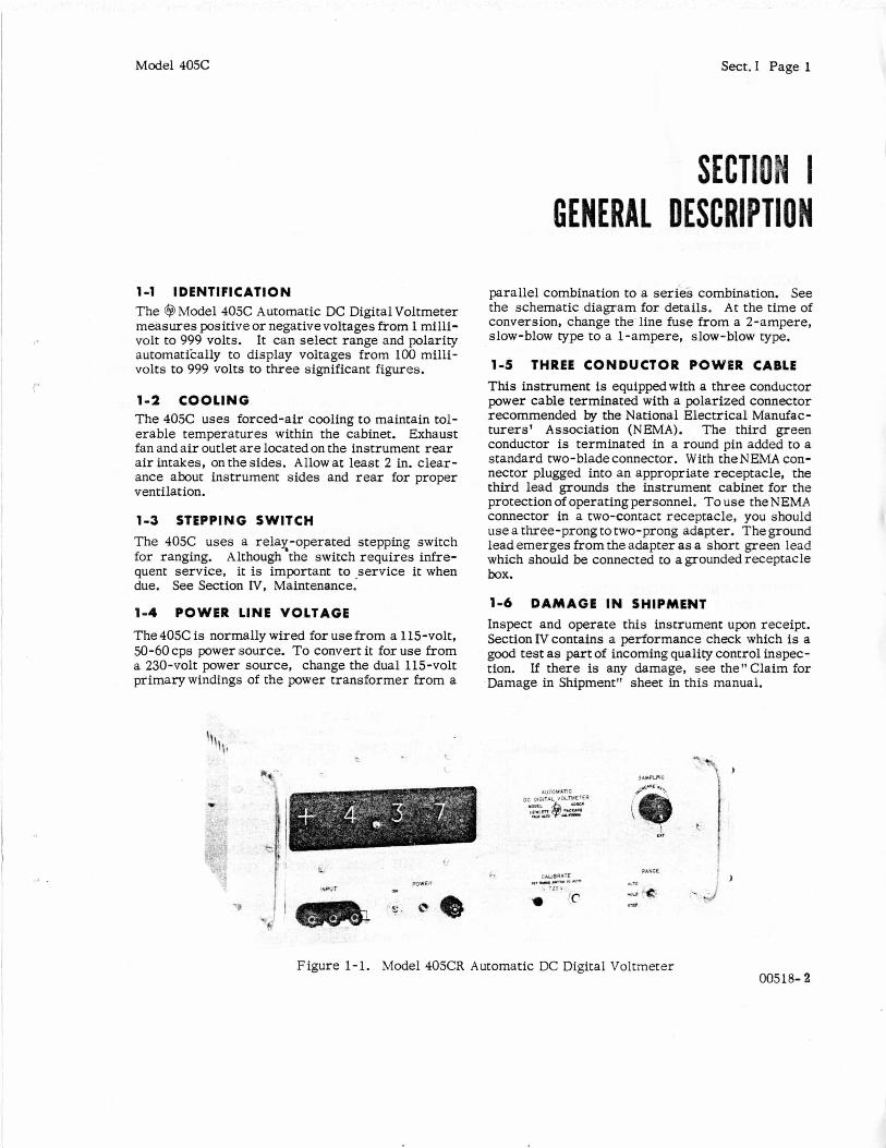
1-1 IDENTIFICATION The 63 Model 405C Automatic DC Digital Voltmeter measures positive or negativevoltages from 1 milli- volt to 999 volts. It can select range and polarity automatikally to display voltages from 100 milli- volts to 999 volts to three significant figures.
1-2 C O O L I N G The 405C uses forced-air cooling to maintain tol- erable temperatures within the cabinet. Exhaust fan and a i r outlet a r e located on the instrument rear a i r intakes, on the sides. Allow at least 2 in. clear- ance about instrument sides and rear for proper ventilation.
1-3 STEPPING SWITCH The 405C uses a relax-operated stepping switch for ranging. Although the switch requires infre- quent service, it is important to -service it when due. See Section IV, Maintenance.
1-4 POWER LINE VOLTAGE
The405C is normally wired for use from a 115-volt, 50-60 cps power source. To convert it for use from a 230-volt power source, change the dual 115-volt primarywindings of the power transformer from a
**-
GENERAL DESCRIPTIO
parallel combination to a series combination. See the schematic diagram for details. A t the time of conversion, change the line fuse from a 2-ampere, slow-blow type to a 1-ampere, slow-blow type.
1-5 THREE CONDUCTOR POWER CABLE
This instrument is equipped with a three conductor power cable terminated with a polarized connector recommended by the National Electrical Manufac- turers' Association (NEMA). The third green conductor i s terminated in a round pin added to a standard two-bladeconnector. With the NEMA con- nector plugged into an appropriate receptacle, the third lead grounds the instrument cabinet for the protection of operating personnel. To use the NEMA connector in a two-contact receptacle, you should use a three-prong to two-prong adapter. The ground lead emerges from the adapter a s a short green lead which should be connected to a grounded receptacle box.
1-6 D A M A G E IN SHIPMENT Inspect and operate this instrument upon receipt. Section IV contains a performance check which is a good test as part of incoming quality control inspec- tion. If there is any damage, see the"C1aim €or Damage in Shipment" sheet in this manual.
i
Figure 1-1. Model 405CR Automatic DC Digital Voltmeter 00518- 2
Section I Page 0
Table 1-1. Specifications
Model 405C
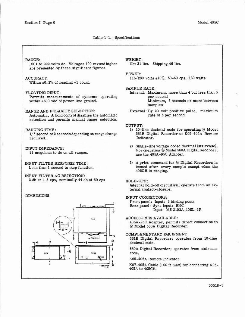
RANGE : . 001 to 999 volts dc. Voltages 100 mvandhigher are presented by three significant figures.
ACCURACY: Within kO. 2% of reading +I count.
FLOATING INPUT: Permits measurements of systems operating within *500 vdc of power line ground.
RANGE ANI) POLARITY SELECTION: Automatic. A hold controldisables the automatic selection and permits manual range selection.
RANGING TIME: 1/5 second to 2 seconds depending on range change required.
INPUT IMPEDANCE: 11 megohms to dc on all ranges.
INPUT FILTER RESPONSE TIME: Less than 1 second to step function.
3 db at 1.5 cps, nominally 44 db at 60 cps INPUT FILTER AC REJECTION:
DIMENSIONS:
T- TOP
WEIGHT: Net 31 lbs. Shipping 46 lbs.
SAMPLE RATE: Internal: Maximum, more than 4 but less than 5
per second Minimum, 5 seconds or more between samples
External: By 20 volt positive pulse, maximum rate of 5 per second
OUTPUT : 1) 10-line decimal code for operating @ Model
561B Digital Recorder or K05-405A Remote Indicator.
2) Single-line voltage coded decimal (staircase). For operating @ Model 560A Digital Recorder, use the 405A-95C Adapter.
3) A print command for @ Digital Recorders is issued after every sample except when the 405CR is ranging.
HOLD-OFF: Internal hold-off circuitwill operate from an ex- ternal contact-closure.
INPUT CONNECTORS: Front panel: Input: 3 binding posts Rear panel: Sync Input: BNC
Input: MS 3102A-lOSL-3P
ACCESSORIES AVAILABLE : 405A-95C Adapter, permits direct connection to @ Model 560A Digital Recorder.
COMPLEMENTARY EQUPMENT: 561B Digital Recorder; operates from 10-line decimal code.
560A Digital Recorder; operates from staircase code. K05-405A Remote Indicator KO?-405A Cable (100 f t max) for connecting K05- 405A to 405CR.
00 518 -3
Model 405C Sect.11 Page 1
2-1 A U T O M A T I C O P E R A T I O N
1) Turn instrument ON. Instrument can be used within 1 minute of turn on, but requires 15 minutes warm up before calibration against internal stand- a rd brings it within specified accuracy. See para- graph 2-3.
2) Set RANGE switch to AUTO.
3) Set SAMPLING control to desired sampling rate. To control sampling rate externally, set SAMP- LING control to EXT and connect triggering signal to EXT TRIGGER connector on instrument rear. Trigger must be a positive s tep at least 20 volts peak and have repetition rate no greater than 5 per second.
NOTE
The instrument requires about 1 second to fully re- spond to sudden input-voltage changes (see para- graph 2-4); therefore delay the external trigger about 1 second after any sudden change in applied voltage.
-
--- -- -- -- --- 4) Connect voltage to be measured to INPUT con- nector and read its value. A parallel INPUT con- nector is located on instrument rear.
CAUTION
When measuring voltage between two points which are both off ground potential, remove the shorting strap between power-line ground and chassis- ground terminals of front-panel INPUT connector. -------------
2-2 M A N U A L O P E R A T I O N
Manual operation permits manual selection of range and is intended for measuring voltages which pro- duce readings of 999 or 100 regardless of decimal position. In either case, a varying input voltage might cause the instrument to continuously change ranges i f .it is operating automatically.
0 PER AT1 NG INSTRUCTIONS Manual operation permits measurement of some voltages to four figures, for the instrument can measure to about 150% of full scale. By holding the instrument on the range just below the correct range, you obtain the second, third, and fourth figures from the readout; the f i r s t figure, which is lost, is always 1. However, instrument accu- racy deteriorates above full scale.
Manual operation is convenient for measuring a series of voltages quite close in value, for the in- strument will not cycle through its ranges as you move the probe from one test point to another.
1) Set RANGE switch to HOLD. Instrument will remain on its displayed range.
2) To change ranges, set RANGE switch to STEP. This is a spring-loaded position, and switch returns to HOLD when released. Instrument s teps to next more positive range each time you release RANGE switch from STEP except that three blank positions occur between +9.99 and +99.9 volt ranges. The decimal point is not lighted on the blank ranges.
2-3 CALIBRATION
The 405C has an internal secondary voltage stand- a rd to check its calibration. The push-button CALIBRATE switch, located on the front panel, applies this voltage to the instrument and discon- nects the INPUT connector. Calibrate the instru- ment, after sufficient warm up, each time you turn it on. Once set, calibration need seldom be checked. Proceed as follows:
1) Turn instrument ON and allow 15 - minute warm up.
2) Set SAMPLING control to maximum sampling rate (full clockwise but not to EXT).
3) Set RANGE switch to AUTO.
4) Note voltage indicated below CALIBRATE en- graving on front panel. This is the internal second- ary standard voltage.
00518-1
Sect.11 Page 2
Voltmeter Indication
+ 3.48
+ .283 - 565.
Model 405C
, Printed Record
348 2
283 3 565-0
5 ) Press CALIBRATE switch and adjust CALI- BRATE control until readout agrees with internal secondary standard voltage.
2-4 INPUT FILTER
The 405C measures instantaneous dc voltages. To avoid readout variations due to superimposed ac signals, the instrument has a low-pass RC filter a t its input. The filter has a sharp cutoff and attenuates 60-cps signals about 50 db. Thus a 60-cps signal with a peak value equal to full scale of the displayed range typically causes a readout variation of * 4 counts.
Since the filter is at the input, it becomes charged to the full value of the input voltage. With the in- put open-circuited (probe lifted off test point), the filter capacitors must discharge through the input attenuator, and after 2 seconds they still haveabout 37% of their original charge. (Youcansee the dis- charge by watching the readout decrease after the probe is removed from a voltage source.) There- fore, if you quickly change the probe from a high- voltage point to a low-voltage point, you will apply nearly the full high voltage stored in the filter capacitors to the low-voltage point through 500K resistance. If the low-voltage point happens to be a high-impedance point such as a vacuum tube grid or, possibly, a transitor element, the voltage ap- plied through the probe may upset circuit oper- ation to the point that the circuit will damage itself. A GOOD OPERATING PRACTICE IS TO TOUCH THE PROBE TO GROUND BRIEFLY OR ALLOW THE FILTER SUFFICIENT TIME TO DISCHARGE WHEN CHANGING THE PROBE FROM HIGH- VOLTAGE POINTS TO LOW-VOLTAGE POINTS. In any case be sure the readout is less than the expected voltage before connecting the probe into a low-voltage circuit.
The input filter makes instrument response to step functions about 0.75 second compared to about 0.2 second between successive samplings a t maximum sampling rate. If you require a response time compatible with maximum sampling rate, remove C1 and replace C2 with two 0.02-pf, ~O-V~CW, polystyrene-dielectric capacitors in series.
CAUTION
Since the two capacitors are in series, one will be off ground potential. Be su re to insulate the off- ground capacitor from the chassis. --------------
Response time will then be about 50 msec. How- ever, ac rejection wil l be much less than with the standard filter. For example, a 60-cps signal with a peak value equal to full scale of the displayed range will cause readout variations a s much as i200 counts.
..
The 405C can drive the 561B directly; the standard 561B cable makes the necessary connections be- tween the voltmeter and recorder. However, the 405A-95C Digital Recorder Adapter is required to connect the 405C to the 560A. The adapter mates with the 100-pin output connector on the rear of the 405C and is held in place by two machine screws. The standard 560A cable connects to the adauter. When connecting either recorder to the 405C, be sure both the recorder and 405A are turned off.
CAUTION The405C chassis is connected to power-line ground through the adapterl550A system. Do not connect the voltmeter common lead to an off-ground potential while the 560A is connected to the voltmeter. This caution also applies when using 405C with Models 561, 562 with dual input couplers. ----------- 2-6 ELECTRICAL OUTPUT I N F O R M A T I O N
You can use the electrical information provided by the 405C for other purposes than operating a re- corder. For example, you might use the information to operate a remote readout identical to the one in the instrument or to record voltage information on punched cards o r tape. Table 2-1 gives ful l details of the information available.
00518-2

Model 405C
Pin
TABLE 2-1. 53 OUTPUT CONNECTOR CHART
Function
Sect. II Page 3
Pin
1 2 3 4
5-11
12
13
14
15
16-25
26 27 28 29 30 31 32 33 34 35
36 37
38
39
40
41-43
44
45-46 47 48
49
50
Connector A (upper)
Function
999-v range 99. 9-v range 1 9.99-v range
999-v range
Decimal information'; stepping switch stator; also see pin 44, J3A.
No connection
Jumpered to pin 38, J3A.
+ l 2 o v * l w o ~
Polarity information: 0 volt on positive ranges, +110 volts on negative ranges; maximum external load 100K.
Polarity information: +110 volts on positive ranges, 0 volt on negative ranges; maximum external load: 20K
No connection
0 1 2 3 4 5 6 7 8 9
Ten-line code, units counter' ; lighted numeral: <+40 volts dark numeral: approx. +lo0 volts maximum load per pin: 500K with pin 13, J3A a s reference
No connection Jumpered to pin 38, J3A
Jumpered to pins 37 and 12, J3A
No connection +3OOvAO% for remote control.Connect to J3A pin; 47 externally f o r remote control of 405C.
No connection
Decimal information' ; stepping switch rotor; also see pins 1-4, J3A
No connection Remote holdoff (see J3A pin 40) Print command -20 volt pulse
Differential print command load lOOK (R107) to 405C chassis
Power-line ground
* Decimal information can be either four-line code or staircase code. For four-line decimal informa- tion, apply a voltage to pin 44, J3A; this voltage is then connected to pin 1, 2, 3, or 4 of J3A depending on the selected range. For staircase decimal in- . formation, apply different voltages to pins 1 through 4, J3A; the voltage corresponding to the range se- lected is then connected to pin 44, J3A.
Pin 13, J 3 A is the ten-line code reference. Avoid applying any load between this pin and ground; use the voltage a8 a reference or bias voltage only.
To utilize ten-line code information, use pin 13, J3A, a s the common return; that is, any load on pins 26-35 of J3A, 1-10 and 16-25 of J3B must re-
1 2 3 4 5 6 7 8 9 10
11 12 13 14
15 16 17 18 19 20 21 22 23 24 25
26-38 39
40 41 42
43
44
45
46 - 50
0 1 \ 2 3 Ten-line code, 4 5 tens counter' . 6 7 8 9 No connection Jumpered to pin 13, J3B Jumpered to pins 12 and 14, J3B Jumpered to pin 13, J3B No connection
8 7 6 Ten-line code, 5 4 hundreds counter' 3 2 1 0
No connection Staircase, units counter'; +135 volts a t
count of zero, equal steps to +55 volts a t count of nine; external load does not affect counting but wil l affect staircase voltage levels; internal imped. 700K.
Staircase, tens counter Staircase, hundreds counter' 405C chassis ground (10 ohms tochassis
ground when K4 energized). +300 volts regulated from external source;
necessary only when regulated stair- case required.
* 110 volts dc from external source to en- ergize K4, which then connects +300 volts supplied at pin 43 to decade
' counters. 6.3 volts ac
I No connection
turn to pin 13, J3A. It ie best to connect any ex- ternal chassis to pin 13, J3A; however, the external chassis will then be about 120 volts positive with respect t o power-line ground and so must have no common connection with power-line ground. The dark-numeral ten-line code voltages require a finite time to reach the final +12Ovolts; however, they are at least +50 volts at the time of the print command.
The +300 volts internally supplied t o the counter units is not regulated; thus the staircase voltages a r e not normally regulated. To obtain regulated staircase voltages, supply regulated +300 volts at 45 ma to pin 43, J3B, and *110 volts a t 12. 5 ma to pin 44, 538 , to energize relay K4, which then applies the external +300volts to the counter units.
0518-2
Sect. I11 Page 0 Model 405C
J I & LOW PASS - F I L T E R
- OSCILLAlOR
RAMP GATE ,
COMMA NO
I I DECIMAL SnlFT RJLSE
PRINT COMMANO PULSE 7
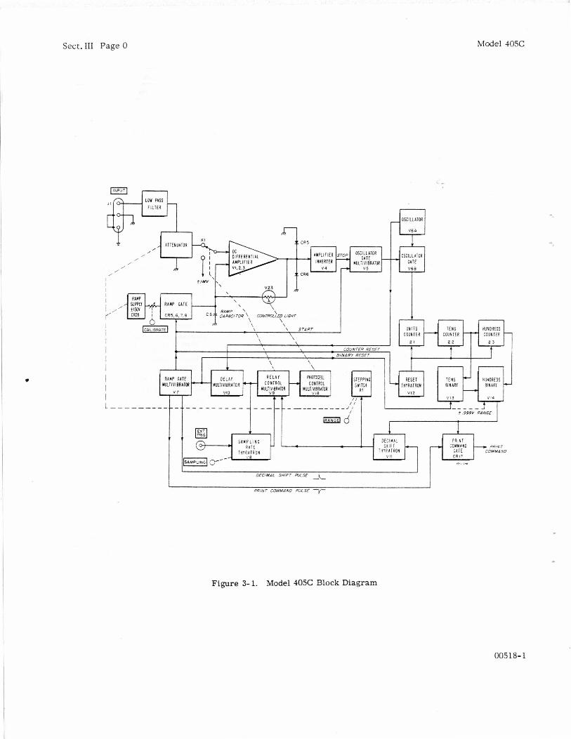
Figure 3- 1. Model 405C Block Diagram
00518-1

Model 405C Sect.111 Page 1
I -
3-1 INTRODUCTION
The 405C is a voltage-to-time converter. It mea- sures the time required for an internally gener- ated voltage (ramp) to increase from essentially zero to the value the input voltage has after pass- ing through an input fi l ter and attenuator. Three decade counters indicate elapsed time by totaliz- ing the output of a 50-kc oscillator for the duration of the time interval. Thus the readoutis a number of time units o r periods of the 50-kc signal. Ramp slope is such that the readout equals the input voltage.
The 405C requires about 0.2 second to make a single measurement; it does not continuously moni- tor its input voltage as do meter-movement types of voltmeters. During the measurement time, the 40% zero-sets itself, makes a measurement,. checks range, and if necessary, changes range. The SAMPLING control determines the rate at which measurements are repeated except that if the instrument is on the wrong range, it will shift range and remeasure at its maximum rate until it finds the correct range.
Figure 3-1 is an over-all block diagram of the Model 405C.
3-2 I N P U T CIRCUIT
The input circuit consists of a Low-Pass Fil ter and an Attenuator. The Low-Pass Fil ter attenu- a tes any ac voltage superimposed on the dc voltage being measured. Cut-off characteristics of the fi l ter a r e such that a 60-cps signal with a peak value equal to full scale of the displayed range causes a readout variation of about i 4 counts,
Four series resis tors make up the Attenuator and provide 1:1, 1O: l . 100:1, and 1OOO:l attenuation. Stepping switch K1, controlled automatically o r by the front-panel RANGE switch, selects the
TIEORY OF appropriate degree of attenuation for the displayed range. Since the Low-Pass Fil ter introduces some attenuation even to dc voltages, the output of the Attenuator is less than *0.999 volt when the dis- played range is correct.
3 -3 VOLT AGE-TO-TI M E C O N V ER4 IO N
The 405C measures the time required for the ramp voltage to increase from essentially zero to the value of the attenuated input voltage. The ramp voltage is the voltage developed across the ramp capacitor a s it charges through a series resistance toward ~t 150 volts. The polarity of the 150 volts is the same a s the polarity of the selected range. The CALIBRATE control permits some adjustment of the series resistance to allow adjustment of the ramp slope.
Ramp Gate Multivibrator V7 s ta r t s the time mea- surement when it opens the Ramp Gate (CR5, CR6, CR7 and CR8) and triggers Oscillator Gate Multi- vibrator V5. The Oscillator Gate Multivibrator opens the Oscillator Gate, V6B, and the counters s ta r t totalizing the output of Oscillator V6A.
A DC Differential Amplifier (Vl, V2 and V3) ends the time measurement by producing a voltage step when ramp voltage equals the attenuated input volt- age. The amplifier has two input grids and ampli- fies the difference between the two applied voltages a thousand times. Two crystal diodes limit the voltage swing a t the output of the amplifier to about 1 volt; thus there is no change in amplifier output until the ramp voltage is within about 0.5 millivolt of the attenuated input voltage. A s the ramp voltage equals and becomes greater than the attenuated in- put voltage, the amplifier output quickly goes from one limit to the other, producing the voltage step. Amplifier Inverter V4 amplifies this voltage step and inverts it, if necessary, to provide a negacive- going input to the Oscillator Gate Multivibrator. This multivibrator then closes the Oscillator Gate,
005 18- 2

Sect. III Page 2 Model 405C
and the counters display thetotal number of pulses which passed through the gate.
The Ramp Gate Multivibrator returns to i t s stable condition, closing the Ramp Gate, about 30 milli- seconds after it starts the ramp; and should there be no output from the amplifier, the Oscillator Gate Multivibrator returns to its stable condition at about the same time. Thus the instrument can count to about 1- 1/2 t imes full scale.
3-4 ZERO-SETTING THE VOLTMETER '
To insure that the ramp always starts from the correct voltage, the ramp is zero-set prior t o each measurement. Two multivibrators, Relay Control Multivibrator V9 and Photocell Control Multivibra- tor V18 zero-set the ramp. The Relay Control Multivibrator energizes a relay which applies a voltage of approximately *l mv to the signal input grid of the amplifier. The polarity of the voltage is always opposite t o the polarity of the displayed range. The Photocell Control Multivibrator illu- minates a photocell V23 in a feedback loop around the amplifier. When the photocell is illuminated its resistance drops to a low value, and full nega- tive feedback is applied to the amplifier. Thus any voltage at the amplifier output is fully fed back to the input and essentially cancelled. Because of the internal unbalance and drift in the amplifier, plus the *l mv applied to the signal input grid. cancellation is not complete. This feedback brings the amplifier output and the corresponding ramp grid input down to less than *lo0 mv. The ramp is zero-set at this time, since the ramp capacitor is connected to the ramp grid of the amplifier and charges to the feedback voltage. Amplifier drift is not fast enough to upset the balance in the t ime of a single measurement. Thus the ramp always s t a r t s from the same zero-set value.
The Photocell Control Multivibrator opens the feed- back loop (by turning off the light shining on the photocell) before the Relay Control Multivibrator de-energizes the relay. Thus the input signal voltage is applied to the amplifier after the feed- back loop opens and cannot upset the ramp zero level. Amplifier output has been reduced to less than 5100 mv as explained in the previous para- graph. With no input the output remains at this level. However, the amplifier gain has gone up to approximately 1000 when the photocell is not illu- minated. Since the signal at the output remains at less than +lo0 mv, the effect of this additional gain is to reduce the apparent input to the amplifier by the amount of the gain. Thus the apparent in- put level has been reduced to less than tlOO pv. Therefore thevoltmeter is zero-set to within 100 pv of zero.
3-5 THE MEASUREMENT PROCESS Sampling Rate Thyratron V8 s t a r t s the measure- ment process by triggering the Relay Control Multi- vibrator, V9. The Relay Control Multivibrator immediately tr iggers Photocell Control Multivi- brator V18, and these two multivibrators zero-set the ramp. After about 80 msec, the Photocell Con- t rol Multivibrator returns to its stable condition, darkening the photocell. Some 30 msec later the Relay Control Multivibrator returns to i t s stable condition, de-energizing the relay and triggei-ing Delay Multivibrator V10. The Delay Multivibrator allows the relay to completely de-energize before the start of the ramp. The delay is about 4 msec.
.
When the Delay Multivibrator returns to its stable condition, it t r iggers the Ramp Gate Multivibrator, V7, to start the ramp and open the Oscillator Gate, V6B. Oscillator V6A synchronizes the return of the Delay Multivibrator t o i t s stable condition. Thus there is no count ambiguity at the s tar t of the ramp. When the ramp voltage equals the attenuated input voltage, the DC Differential Amplifier closes the Oscillator Gate, and the readout indicates the volt- age applied to the instrument.
3-6 CHECKING RANGE
During each measurement the 405C checks the range by monitoring the output of the Tens and Hundreds Counters. If there is no output from the Tens Counter, the range is too high, for the ramp voltage equals the attenuated input voltage before the counters register 100 counts. If the Hundreds Counter produces an output, the range is too low, o r the displayed polarity is wrong, for the counters count off scale before the ramp voltage equals the attenuated input voltage. Thus the range is correct only when the Tens Counter produces at least one output pulse, while the Hundreds Counters produce none. However. on the most sensitive ranges, (+. 999 v), the Tens Counter is effectively bypassed. This action permits the counters t o display levels of less than 100 counts, during which time the Tens Counter is unable to produce an output pulse.
Tens Binary V13 and Hundreds Binary V14 do the monitoring. The Tens Binary is reset by Delay Multivibrator V10 when that multivibrator tr iggers the Ramp Gate Multivibrator. The Tens Binary in turn resets the Hundreds Binary. (Binaries have two stable conditions. Hereafter, condition 0 is the reset condition; condition 1, the non-reset con- dition. ) With no output from the Tens Counter, both binaries remain in condition 0. The first out- put pulse from the Tens Counter switches the Tens Binary to condition 1. and the Tens Binary immedi- ately switches the Hundreds Binary to condition 1 also. Succeeding pulses from the Tens Counter
00518- 1
Model 405C Sect.III Page 3
have no effect. The first output pulse from the Hundreds Counter switches the Hundreds Binary back to condition 0. Succeeding pulses have no effect. Therefore, if the measurement ends with the Hundreds Binary in condition 1, the range is correct; if the measurement ends with the Hundreds Binary in condition 0, the range is wrong.
There is a direct reset line from the Delay Multi- vibrator to the Hundreds Binary (not shown in Figure 3-1); so the Delay Multivibrator directly resets the Hundreds Binary in the event the Tens Binary is in condition 0 and the Hundreds Binary in condition 1, should this combination occur. Also, on the *. 999 v range, when no logic pulse is avail- able f rom the now by-passed Tens Binary, this line serves to reset the Hundreds Binary to con- dition 0, where it remains. However, if the range is too low, an output pulse will be produced by the Hundreds Counter which immediately resets the Hundreds Binary to condition 1.
3-7 DECIMAL SHIFT CONTROL
The Hundreds Binary determines whether o r not the 405C shifts range by controlling Decimal Shift Thyratron V11 and Print Command Gate CR17. When in condition 1 (correct range), the Hundreds Binary holds the Decimal Shift Thyratron off and opens the Print Command Gate. When in condi-
tion 0 (wrong range), the Hundreds Binary le ts the Decimal Shift Thyratronfire if triggered and closes the Print Command Gate.
When the Ramp Gate Multivibrator returns to i ts stable condition and closes the Ramp Gate, it ap- plies a positive pulse to the Decimal.Shift Thyra- tron and a negative pulse to the Print Command Gate. If the range is correct, the negative pulse passes through the Print Command Gate to be used as a trigger fo r a remote recorder. The Decimal Shift Thyratron is held off. If the range is wrong, the Print Command Gate is closed, but the posi- tive pulse fires the Decimal Shift Thyratron. The Decimal Shift Thyratron then shifts the instrument to the next more positive range (by moving Step- ping Switch K l one step) and t r iggers Relay Control Multivibrator V9 to s ta r t another measurement.
When triggered, the Relay Control Multivibrator t r iggers Sampling Rate Thyratron V8. The Sam- pling Rate Thyratron then cannot f i re during a measurement started by the Decimal Shift Thyra- tron.
To prevent continual recycling when the 405Ameas- ures voltages f rom 4 . 0 9 9 to -0.099 volt, the Hun- dreds Binary is reset t o condition 1 on the +. 999 and -. 999 volt ranges. Thus the instrument shifts from these ranges only after off-scale counts.
00518- 1

Model 405C
4-1 INTRODUCTION
This section contains maintenance and servicing information for the 405C with the exception of its decade counter units. Information covering these units is contained in the AC-4 Decade Coun- ter Manual.
Included in this section is a performance check to verify instrument operation. The check can be made with the instrument in its cabinet and is a good test as part of preventive maintenance and incoming quality control inspection.
The stepping switch used for ranging requires periodic cleaning and lubrication. It is important to service i t when due. See paragraph 4-9 .
8
4-2 TEST EQUIPMENT
The following is a list of recommended test e q u i p ment for servicing and trouble shooting your 405 C :
1) A dc voltmeter having an input resistance of at least 100 megohms. Recommended @ equipment: 410B Vacuum Tube Voltmeter or 412A DC Vacuum Tube Voltmeter.
2) Trigger generator to provide a 20-volt positive pulse for triggering the 405C externally. Re- commended !@ equipment: 202A Low Frequency Function Generator.
3) Calibration generator to check calibration and tracking of the 405C. Generator output should be adjustable in steps of millivolts, tenths of volts, and volts, and should be accurate within 0.1%. Re- commended @ equipment: Model 738AR Volt- meter Calibrator.
4) Oscilloscope to check circuit waveforms. The oscilloscope should have an upper frequency limit of at least 200 kc. Recommended @ equipment: 120A Oscilloscope.
Sect. IV Page 1
SECTION IV
5) Ohmmeter. Recommended Q equipment: 410B Vacuum Tube Voltmeter or 412A DC Vacuum Tube Voltmeter.
6) Variable power transformer to vary line voltage between 103, 115 and 127 volts. The transformer should have a current capacity of a t least 3 amps, and its output voltage should be monitored by a voltmeter accurate within * 1 volt.
4-3 PERFORMANCE CHECK
A. TRACKING AND RANGING CHECK
1) Turn instrument on, set line voltage to 115 volts, and allow 5-minutes warm up.
2) Set RANGE switch to AUTOand SAMPLING con- trol to maximum (clockwise) but not to EXT.
3) Connect calibration generator to 405C INPUT connector and adjust generator output to +0.8 volt. Adjust 40.5'2 CALIBRATE control to produce read- Out of + .800.
4) Check 405C readout against calibration gener- ator output voltages listed below: 405A indication should be within 0.2% *1 count of generator output at all voltages.
000 + .1 + .8 + 20 + . 001 + .2 + .9 + 30 + .002 + .3 +1 + 50 + .003 + .4 + 2 + 100 + .010 + .5 + 3 + 200 + .02 + .6 + 5 + 300 + .03 + .7 + 10
5) Repeat step 4 for negative voltages.
6 ) Repeat step 4 and 5 at line voltages of 103 and 127 volts.
005 18- 2
Sect.IV Page 2 Model 405C
B. EXTERNAL TRIGGER CHECK
1) Set SAMPLING control to EXT.
2) Connect trigger generator to EXT TRIG con- nector on rear of 405C.
3) Adjust trigger generator output for positive pulse (square wave wil l do) 20volts peak. Set trig- ger repetition rate to 5 per second and observe 405C readout. If it is not apparent that 405C is sampling five times per second, vary voltage applied to INPUT connector and watch rateat which readout changes.
C. CALIBRATION STANDARD CHECK
before you make this check.) (Instrument must have 15 minutes warm up
1) Set SAMPLING control to maximum (clockwise) but not to EXT, and set RANGE switch to AUTO.
2) Connect calibration generator to 405C INPUT connector and adjust generator output to + 0.8 volt.
3) Adjust 405C CALIBRATE control to produce readout of +.800.
4) P r e s s CALIBRATE switch; readout should agree with voltage stamped on tag under CALI- BRATE engraving on front panel.
D. MANUAL RANGING CHECK
1) Set RANGE switch to HOLD. Range should re- main constant regardless of voltage applied.
2) Set RANGE switch to STEP and release. In- strument should step to next more positive range except that three blank positions occur between +9.99 and +99.9 volt ranges. The decimal point is not lighted on the blank ranges.
4-4 CABINET R E M O V A L
The 405C has top and bottom dust covers. Each cover is held by two screws in the rear . When sliding either cover off, you may have to l i f t the front edge of the cover to clear internal components.
NOTE
Turn the 405C off before removing or replacing the dust covers. -----------------
4-5 POWER SUPPLIES
Check power supply voltages and regulation a s part of routine maintenance and a s a first trouble- shooting step. If the voltages a r e essentially cor- rect and properly regulated (the +300 and +120 supplies a r e not regulated), the supplies a r e oper- ating properly.
You can check regulation of the power supplies by monitoring their voltages while varying line voltage between 103 and 127 volts. The regulated voltages should vary only slightly, if a t all, from the value measured at a 115-volt line. Figure 4-5 shows convenient points to measure the voltages.
The 250-volt supply is the only adjustable supply, and it should seldom require resetting. If you do adjust it, u se a voltmeter accurate within 3% of full scale and following the adjustment checkampli- fier balance (paragraph 4-6) and neutralization (paragraph 4-7).
4-6 B A L A N C I N G THE AMPLlFlER
1) Remove top dust cover.
2) Set line voltage to 115 volts, turn instrument on and allow 5-minutes warm up.
3) Set RANGE switch to AUTO and SAMPLING control to maximum (clockwise) but not to EXT.
4) Connect calibration generator to 405C INPUT connector and set generator output to+0.8 volt (any convenient voltage will do provided you can change its polarity without changing its amplitude).
5) Adjust CALIBRATE control until voltmeter reads +.800.
6) Change calibration generator output to -0.8 volt.
7) Adjust Coarse Bal R14 until 405C reads -.800.
8) Repeat steps 4 through 7 until 405Creads +.800 and -.800 without adjustment.
00518-1
Model 405C Sect.IV Page 3
4-7 NEUTRALIZING THE AMPLIFIER
1) Remove bottom dust cover.
2) Set line voltage to 115 volts. turn instrument on, and allow 5-minutes warm up.
3) Set RANGE switch to AUTOand SAMPLING con- t rol to maximum but not to EXT.
4) Connect direct short across 405C INPUT.
5) Adjust Amp Neut control C10 to set readout to +. 000. This control is mounted on socket of V3.
4-a ~ O S A - ~ S C ADAPTER ADJUSTMENT
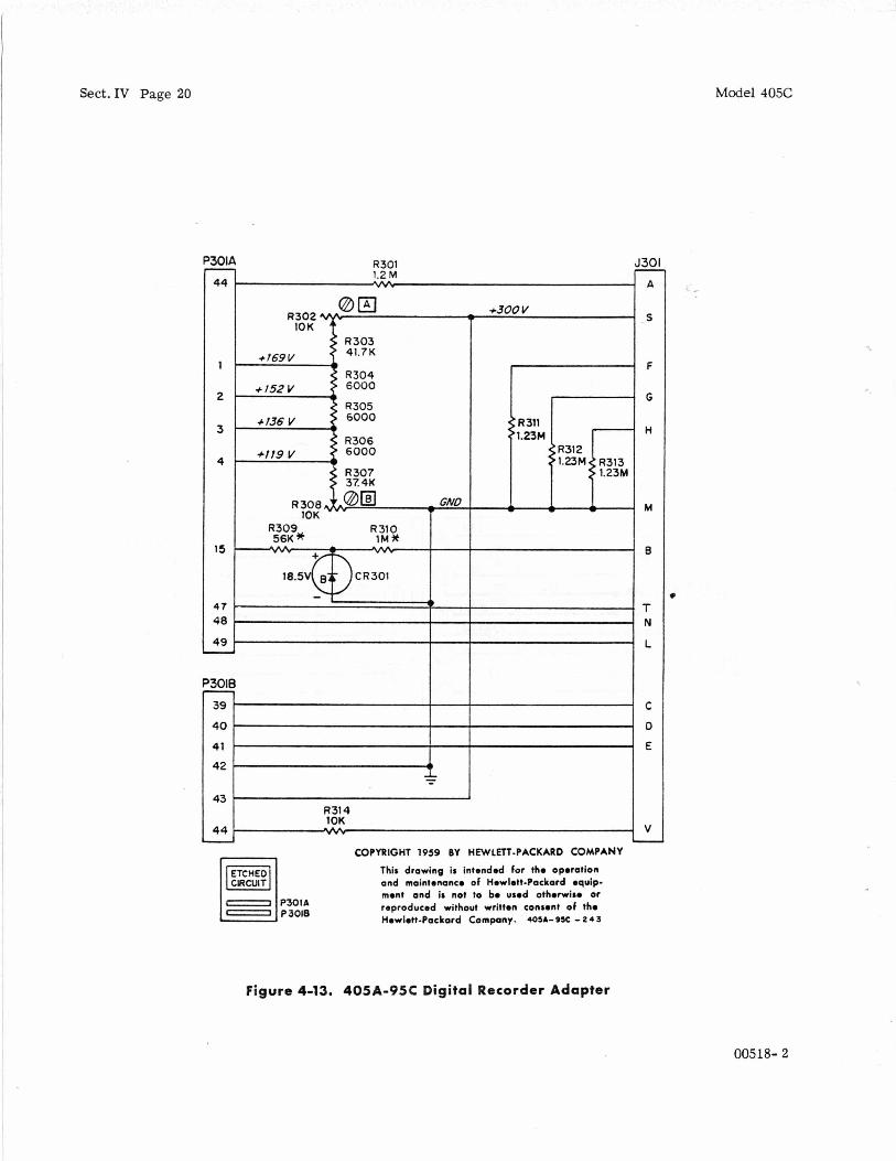
The only adjustment required by the 405A-95C Digital Recorder Adapter is the adjustment of the s ta i rcase voltages for range indication on the @ Model 560A Digital Recorder. Proceed as follows:
1) Connect Adapter to Recorder only and turn Re- corder on.
2) Adjust R302 (A) and R308 (B) in Adapter until voltages at pins 1 and 4 of P301A are +169 and -1-119 respectively. Use the 405C to measure the voltages, for they should be set as close as pos- sible to their correct values.
4-9 STEPPING SWITCH MAINTENANCE
The stepping switch should be kept clean and well lubricated. Inspect the switch according to the schedule below and add lubricant o r clean and re- lubricate as necessary.
1) After 30,000 revolutions or three months, which- ever is first.
2) After each additional 150, 000 revolutions or six months, whichever is more frequent.
To obtain the best resul ts from 'maintenance lubri- cation, first wipe the par t s as clean as possible. If the switch is excessively dirty, clean it with a high-quality cleaner such as xylene which does not leave a film upon evaporation.
A lubrication kit consisting of three types of lubri- cant, each in a small bottle, is included with your instrument. Each bottle has a geometric figure (and the switch manufacturer's specification num- ber) on it for easy identification in the lubrication procedure below. Each bottle cap has attached to it the type of brush best suited for the particular lubricant.
When lubricating the stepping switch, it is important to apply the right amount of lubricant. Too much can be as bad as not enough. To assure the proper amount, the te rm "dip" will be used as a guide. To obtain one "dip" of lubricant, dip the brush into the lubricant, then wipe the brush against the side of the bottle to remove the drop that forms at the end of the brush. In most cases one dip will be enough to lubricate several parts. Brush the lubricant lightly over the parts. Do not scrub the brush on the parts because such action usually resul ts in too much lubricant on the f i rs t part and too little on the others .
During manufacture the undercut portion of the wiper shaft is filled with ANG-3-A grease, and a small portion of this grease is applied to the end of the shaft opposite the mounting hub before the shaft is assembled into the hub. This lubrication is good for the life of the switch and needs repla- cing only when the wiper assembly is replaced.
A. EXPOSING THE SWITCH FOR LUBRICATION
1) Remove stepping switch cover. See Figure 4-4.
2) Remove nuts that hold stepping switch mounting bracket to deck.
3) Remove screws holding switch to bracket and remove bracket.
4) Lift switch up through deck. You may have to remove relay K2 to make room. Reverse proce- dure to replace switch.
B. LUBRICATING THE STEPPING SWITCH
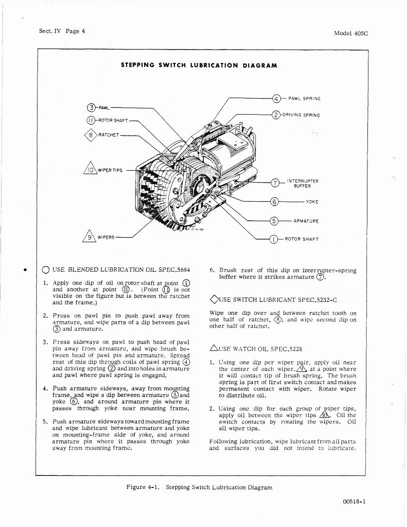
are shown in Figure 4-1. The lubricating points for the stepping switch
4-10 TUBE A N D DIODE REPLACEMENT
A. TUBE REPLACEMENT
In many cases of instrument malfunction, the cause is a weak or defective tube. Locate the trouble as nearly as possible and'check the tubes in the suspected circuits.
The best tube checker is the circuit in which a tube must operate. Check tubes by substitution and re- place the original one if a newone does not res tore proper circuit operation. However, if circuit con- dition (burned resistor, etc. ) indicates that the original tube may be shorted o r otherwise mechan- ically defective, check the tube on a "tube tester" before returning it to the circuit.
00518- 1
Sect.IV Page 4 Model 405C
STEPPING S W I T C H L U B R I C A T I O N D I A G R A M
PAWL SPRING
fi ROTOR SHAFT -
/9\ WIPERS 2
INTERRUPTER
0 USE BLENDED LUBRICATION OIL SPEC.5684
1. Apply one dip of oil on rotorshaft at oint @ and another at point 0. (Point 6 is not visible on the figure but i s between the ratchet and the frame.)
2. Press on pawl pin to push pawl away from armature, and wipe parts of a dip between pawl @ and armature.
3. Press sideways on pawl to push head of pawl pin away from armature, and wipe brush be- tween head of pawl pin and armature. Spread rest of this dip through coils of pawl spring @ and driving spring @ and into holes in armature and pawl w h e r e pawl spring is engaged.
4. Push armature sideways, away from mounting frame, and wipe a dip between armature @and yoke 8. and around armature pin where it passes through yoke near mounting frame.
5. Push armature sideways toward mounting frame and wipe lubricant between armature and yoke on mounting-frame side of yoke, and around armature pin w h e r e it passes through yoke away from mounting frame.
6. Brush rest of this dip on interrupter-spring buffer where it strikes armature 0.
O U S E SWITCH LUBRICANT SPEC.5232-C
Wipe one dip over and between ratchet tooth on one half of ratchet, @, and wipe second dip on other half of ratchet.
A U S E WATCH OIL SPEC.5228
1. Using one dip per wiper pair, apply oil near the center of each w i p e r , h at a point where it will contacr tip of brush spring. The brush spring is part of first switch contact and makes permanent contact with wiper. Rotate wiper to distribute oil.
2. Using one dip for each group of iper tips, apply oil between the wiper tips A. Oil the switch contacts by rotating t h e wipers. Oil all wiper tips.
Following lubrication, wipe lubricant from all parts and surfaces you did not intend to lubricate.
Figure 4-1. Stepping Switch Lubrication Diagram
00518-1
Model 405C Sect.IV Page 5
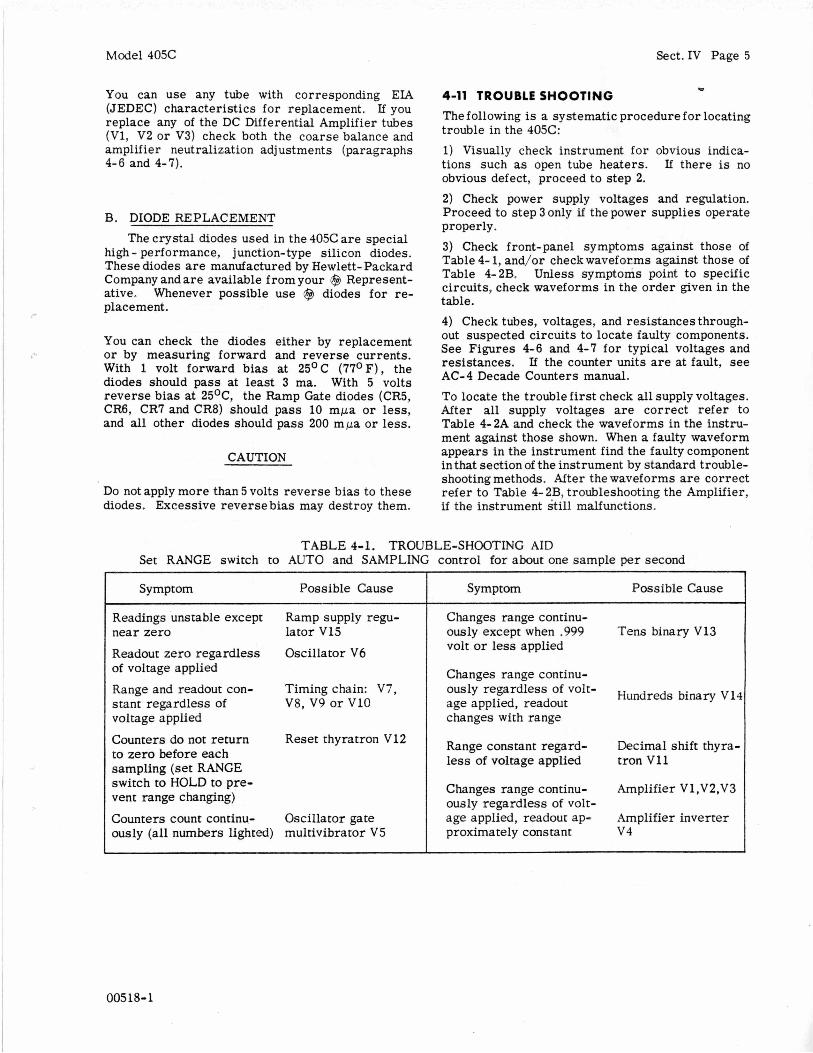
You can use any tube with corresponding ELA (JEDEC) characteristics fo r replacement. If you replace any of the DC Differential Amplifier tubes (Vl, V2 or V3) check both the coarse balance and amplifier neutralization adjustments (paragraphs 4-6 and 4-7).
B. DIODE REPLACEMENT
The crystal diodes used in the 405C are special high - performance, junction-type silicon diodes. These diodes are manufactured by Hewlett- Packard Company andare available from your @ Represent- ative. Whenever possible use @ diodes for re- placement.
You can check the diodes either by replacement or by measuring forward and reverse currents. With 1 volt forward bias at 25OC (77OF), the diodes should pass at least 3 ma. With 5 volts reverse bias at 25OC, the Ramp Gate diodes (CR5, CR6, CR7 and CR8) should pass 10 mpa or less, and all other diodes should pass 200 m p a or less.
CAUTION
Do not apply more than 5 volts reverse bias to these diodes. Excessive reverse bias may destroy them.
w 4-11 TROUBLE SHOOTING The following is a systematic procedure for locating trouble in the 40%:
1) Visually check instrument for obvious indica- tions such as open tube heaters. If there is no obvious defect, proceed to s tep 2. 2) Check power supply voltages and regulation. Proceed to step 3 only i f the power supplies operate properly. 3) Check front-panel symptoms against those of Table 4- 1, and/or checkwaveforms against those of Table 4-2B. Unless symptoms point to specific circuits, check waveforms in the order given in the table.
4) Check tubes, voltages, and resistances through- out suspected circuits to locate faulty components. See Figures 4-6 and 4-7 for typical voltages and resistances. If the counter units are at fault, see AC-4 Decade Counters manual. To locate the trouble first check all supply voltages. After all supply voltages are correct refer to Table 4-2A and check the waveforms in the instru- ment against those shown. When a faulty waveform appears in the instrument find the faulty component in that section of the instrument by standard trouble- shooting methods. After the waveforms are correct refer to Table 4-2B, troubleshooting the Amplifier, if the instrument still malfunctions.
TABLE 4-1. TROUBLE-SHOOTING AID Set RANGE switch to AUTO and SAMPLING control for about one sample per second
Symptom Possible Cause
Readings unstable except Ramp supply regu- near zero lator V15
Readout zero regardless Oscillator V6 of voltage applied
Range and readout con- Timing chain: V7 stant regardless of voltage applied
Counters do not return to zero before each sampling (set RANGE switch to HOLD to pre- vent range changing)
Counters count continu- Oscillator gate ously (all numbers lighted) multivibrator V5
V8, V9 o r V10
Reset thyratron V 2
Symptom Possible Cause
Changes range continu- ously except when .999 volt or less applied
Tens binary V13
Changes range continu- ously regardless of volt- age applied, readout Hundreds binary v14
changes with range
Range constant regard- less of voltage applied
Decimal shift thyra- tron V11
Changes range continu- Amplifier Vl,V2,V3 oualy regardless of volt- age applied, readout ap- Amplifier inverter proximately constant v4
005 18- 1
Sect.IV Page 6 Model 405C
+ 50
-50 0'
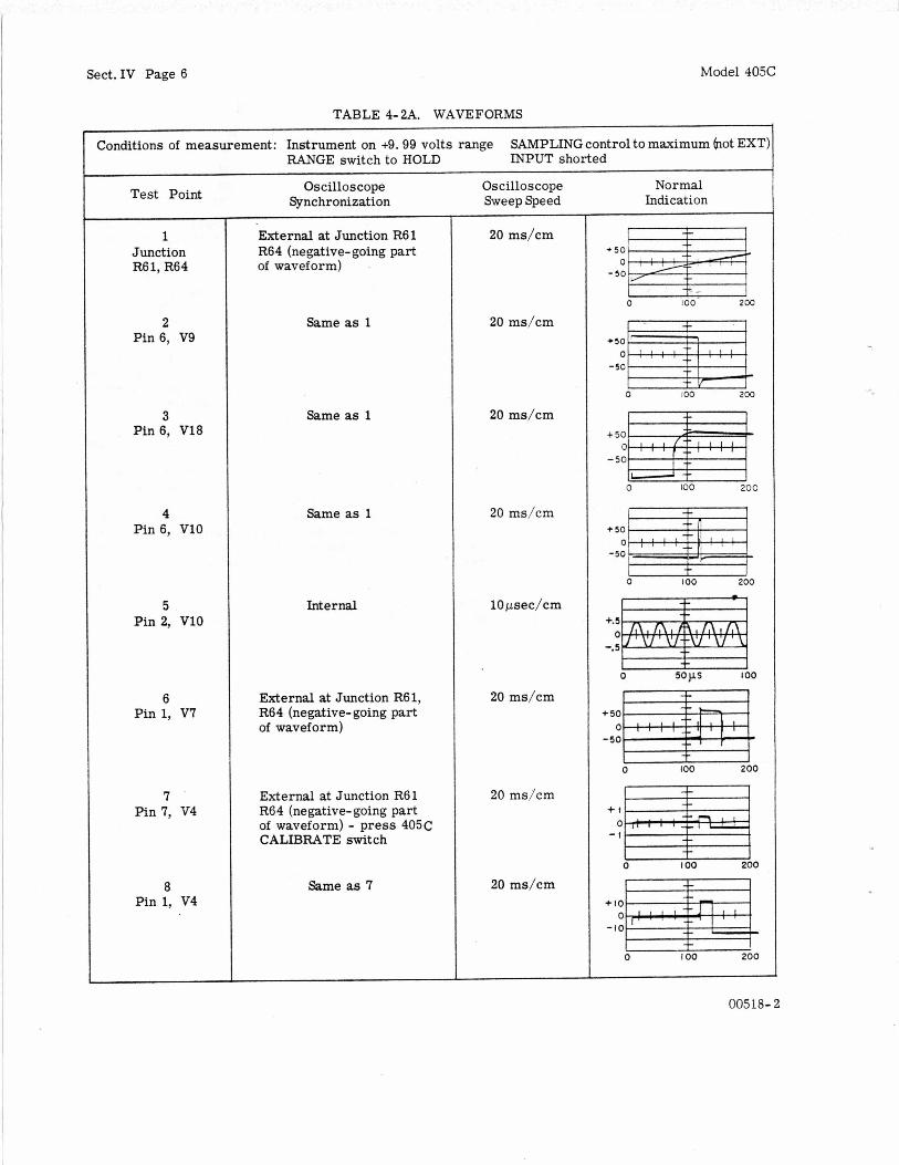
TABLE 4- 2A. WAVEFORMS
Conditions of measurement: Instrument on +9.99 volts range RANGE switch to HOLD
SAMPLING control to maximum (not EXT: INPUT shorted
+ n : : I ! : ! .
t
Test Point
1 Junction R61, R64
2 Pin 6, V9
3 Pin 6, V18
4 Pin 6, V10
5 Pin 2, V10
6 Pin 1, V7
7 Pin 7, V4
8 Pin 1, V4
Oscilloscope Synchronization
External at Junction R61 R64 (negative-going part of waveform)
Same as 1
Same as 1
Same as 1
Internal
External at Junction R61, R64 (negative-going part of waveform)
External at Junction R61 R64 (negative-going part of waveform) - press 405C CALIBRATE switch
Same as 7
Oscilloscope Sweep Speed
20 ms/cm
20 ms/cm
20 ms/cm
20 ms/cm
lOpsec/cm
20 ms/cm
20 ms/cm
20 ms/cm
Normal Indication *5:w4 - 50
+ 5 : F I
0 I00 200
-50
0 IO0 2 0 0
- 5 0
0 100 200
0 +tm - 1
u 0 I O 0 200
00518- 2

Model 405C
SAMPLING RATE THYRATRON
PHOTO CELL M U L T I V I ~ R A T O R I
TABLE 4-2A. WAVEFORMS (CONT’D)
V8 . vie .
Sect.IV Page 7
RELAY CONTROL MULTIVIBRATOR,
Test Point
V 9 B 4 ,
RAHPMULTI I ‘J7 DELAY V I O m
v5 OSC M U L T l I 1, c .5 -w
’
9 Pin 6, V5
10 Pin 3, XZlA
11 Pin 1, V13
12 Pin 1, V14
Oscilloscope Synchronization
Same as 7
External at pin 1, V10 with input (negative- going par t of waveform)
Same as 10
Same as 10
Oscilloscope Sweep Speed
20 ms/cm
20 ms/cm
20 ms/cm
20 ms/cm
Normal Indication
I -L 1
u 0 100 200
I + I - 0 10 20
+ 5 ~ ~
+ 5 ~ ~ ~
-50
0 IO 20
- 50
0 10 20
TABLE 4- 2B. TROUBLESHOOTING THE AMPLIFIER
Make sure all waveforms agree with those shown in Table 4-2A before proceeding fur- ther. 1) Connect an oscilloscope for external syn- chronization (negative input) from pin 6, V8 of the Model 405C. Connect vertical input to pin 7, V4 of Model 405C.
2) Momentarily depress the RANGE switch until the instrument is on the +l volt range (polarity sign and decimal light lit as shown in the title page photograph).
3) Compare waveforms. If different, trouble is in amplifier. Determine where waveform first deviates from that shown. Arrows at bottom show time relationship of the opera- tion cycle of the tubes called out by V num- bers. Comparison of point of deviation of waveform and time relationships will deter- mine faulty section. If you obtain proper waveform but instrument still malfunctions, check decade counters, oscillator gate multi- vibrator or oscillator.
Sect.IV Page 8 Model 405C
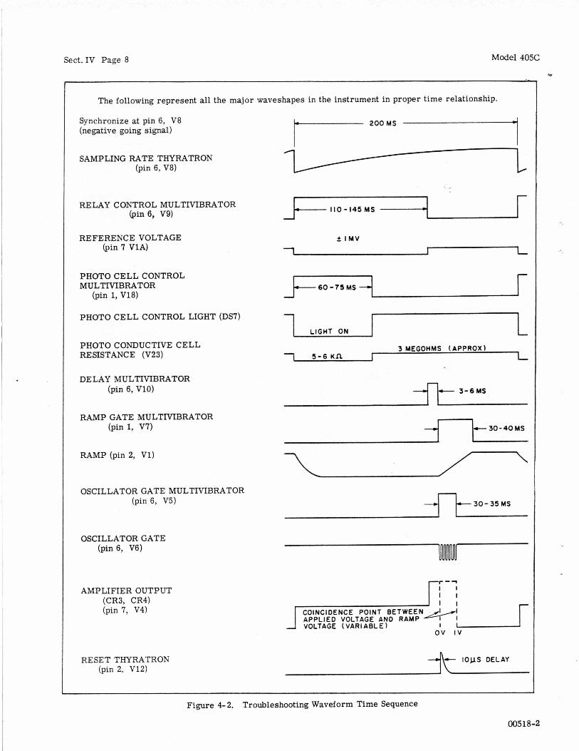
The following represent all the major waveshapes in the instrument in proper time relationship.
Synchronize at pin 6, V8 (negative going signal) r 200MS A ‘1 SAMPLING RATE THYRATRON
(pin 6, V8)
RELAY CONTROL MULTIVIBRATOR (pin 6, V9) 110 - I45 MS
REFERENCE VOLTAGE (pin 7 V1A)
5 I M V
1
PHOTOCELLCONTROL MULTIVIBRATOR
(pin 1, V18) 6 0 -75 MS
PHOTO CELL CONTROL LIGHT (DS7)
LIGHT ON
1 5 - 6 Kn r PHOTO CONDUCTIVE CELL RESISTANCE (V23)
DE LAY MULTMBRATOR (pin 6, VlO) 3 - 6 MS
RAMP GATE MULTMBRATOR (pin 1, V7) 3 0 - 4 0 M S
RAMP (pin 2, VI) 7 OSCILLATOR GATE MULTIVIBRATOR
(pin 6, V5) 4-l- 30- 35 MS
OSCILLATOR GATE (pin 6, V6)
AMPLIFIER OUTPUT (CR3, CR4) (pin 7, V4)
VOLTAGE ( VARl ABLE 1 ov I V
RESET THYRATRON (pin 2, V12)
Figure 4- 2. Troubleshooting Waveform Time Sequence
00518-2

Model 405C Sect. Iv Page 9
t I oov
The following are normal waveshapes which will enable you to find trouble in the automatic ranging section of the instrument.
~
Connect vertical input of oscilloscope to pin 1 V14 (Hundreds Binary). Synchronize (negative going dc coupled) on pin 6 of V10 (Delay Multivibrator) with RANGE switch on HOLD. Sweep speed 5 milliseconds per centimeter.
Range i 1 to 9.99V. Input greater than lV, but less than 10 volts. (i indicates both either + o r -)
Range * . 0001 to .999V. Input less than f 1 volt.
Range *l to 9.99V. Input greater than f 10 volts.
Range +1 to 9.99V. Input +O. 9 volts.
Range +1 to 9.99V. Input 4 . 4 volts
Range * . 001 to .999V. Input greater than il volt.
0 5 10 15 20 25 30 35 t 200v
t IOOV
0
Model 405 should not range in AUTO position.
+200v
t IOOV
0 Model 405 should range in AUTO position.
+200v
f l O O V
0 Model 405 should range in AUTO position.
+200v
t IOOV
0
Model 405 should range in AUTO position.
t 200v
t IOOV
Figure 4- 3. Ranging Troubleshooting Waveforms
00518-1
..

Sect.IV Page 10
J3A&8 DIGITAL RECORDER OUTPUT
\
Model 405C
J4 J 2 INPUT EXT TRIGGER (PARALLELS FRONT
PANEL INPUT J l )
c
\ OVEN FOR
INTERNAL STANDARD AND RAMP SUPPLY
/ / AMI? COARSE BAL.
STEPPING SWITCH COVER REGULATOR
MP-S- 773
Figure 4-4. Top Internal View of Model 405C
00518-1
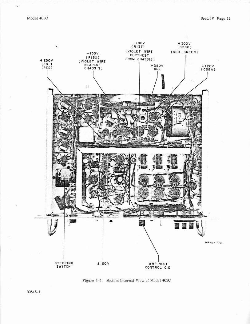
Model 4032
- 1 4 0 V ( R l 3 7 )
Sect.IV Page 11
+ 3 0 0 V ( C 5 8 C 1 b
( V I O L E T WIRE ( RED - G R E E N ) F U R T H E S T
FROM CHASSIS )
- l 5 0 V ( R l 3 0 )
-b 2 5 O V ( V I O L E T WIRE NEAREST I t 2 5 0 V + I20 ( C 6 1 1
( R E D ) C H A S S I S ) ADJ.
I - -
I. ’
w - s - 773
S T E P P I N G S W I T C H
00518-1
f l 5 0 V A M P ‘NEUT CONTROL CIO
Figure 4-5. Bottom Internal View of Model 405C
Sect.IV Page 12 Model 405C
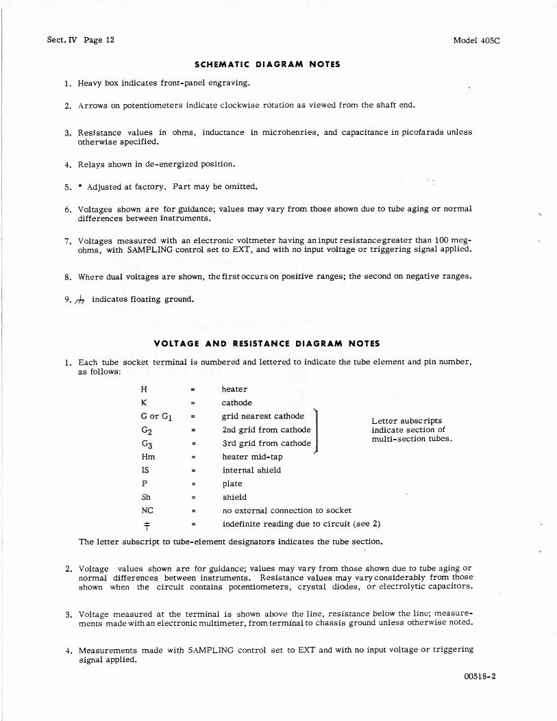
SCHEMATIC D I A G R A M NOTES
1. Heavy box indicates front-panel engraving.
2. Arrows on potentiometers indicate clockwise rotation as viewed from the shaft end.
3. Resistance values in ohms, inductance in microhenries, and capacitance in picofarads unless otherwise specified.
4. Relays shown in de-energized position.
5. * Adjusted at factory. Part may be omitted.
6. Voltages shown a r e for guidance; values may vary from those shown due to tube aging or normal differences between instruments.
7. Voltages measured with an electronic voltmeter having an input resistancegreater than 100 meg- ohms, with SAMPLING control set to EXT, and with no input voltage or triggering signal applied.
8. Where dual voltages a r e shown, the first occurs on positive ranges; the second on negative ranges.
9. indicates floating ground.
V O L T A G E A N D RESISTANCE D I A G R A M NOTES
1. Each tube socket terminal is numbered and lettered to indicate the tube element and pin number, as follows:
heater cathode
2nd grid from cathode !
3rd grid from cathode 1
grid nearest cathode
heater mid-tap internal shield plate shield no external connection to socket indefinite reading due to circuit (see 2)
1 Letter subscripts indicate section of multi-section tubes.
The letter subscript to tube-element designators indicates the tube section.
2. Voltage values shown a r e for guidance; values may vary from those shown due to tube aging or normal differences between instruments. Resistance values may vary considerably from those shown when the circuit contains potentiometers, crystal diodes, o r eleccrolytic capacitors.
3. Voltage measured at the terminal is shown above the line, resistance below the line; measure- ments made with an electronic multimeter, from terminal to chassis ground unless otherwise noted.
4. Measurements made with SAMPLING control set to EXT and with no input voltage or triggering signal applied.
00518-2
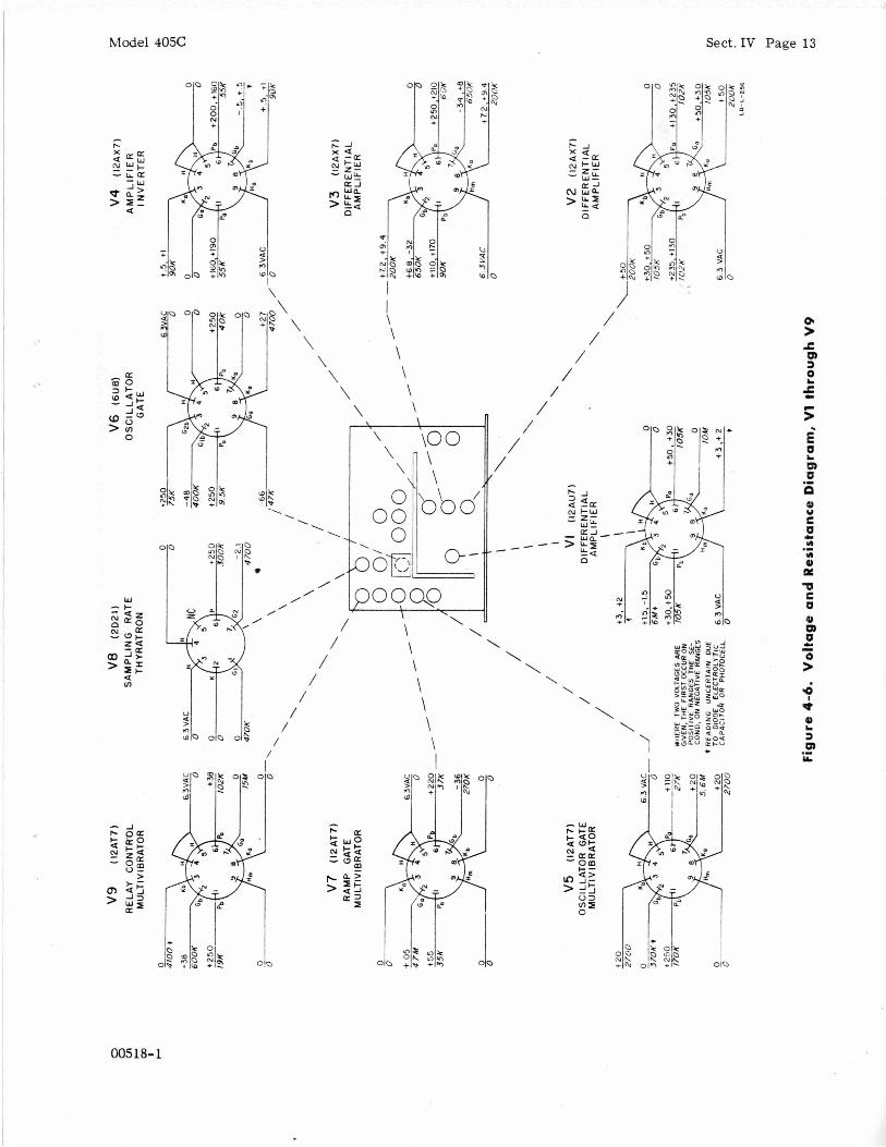
Model 405C Sect.IV Page 13
00518-1

Model 405C i Sect.IV Page 14
I
I I I
I
/ /
/ /
00518-1

Model 405C Sect.IV Page 15
I .
1,5v ~ 4c
REF. C E S I G N I T O R S
C56 - 67 C R a - 3 0
13116 -140
'416- I8
U N I S S I G V E 0: C62,63 CR23 -30 RllCI-l2l, i39
15ov
140Y
CR 27 R133 RI35 R137 5600 3900 IO00
R134 R136 5600 3900
- 4Nc T - -1
V I5 O A 2
RECU L A TOR
9 9 9 9
Figure 4-8. Power Supply
005 18- 3
..

Sect.IV Page 16 Model 405C
L
-8
" n ^ N
OO518- 3

Model 405C Sect.IV Page 17
: : D m m m * *
a x A
00518-3
Sect.IV Page 18
. 5 Y
I I ,, I I . .r 1
Model 405C
v * b P I
O O O Q O I I I I I I I
g4-gf 0' h P
h c V
z z 8
u f
t z V
y1
CR c a .-
c c
d
00518-3
Model 405C Sect.IV Page 19
REmffG +-+ttOV rilFD/Off KID 4
0 0
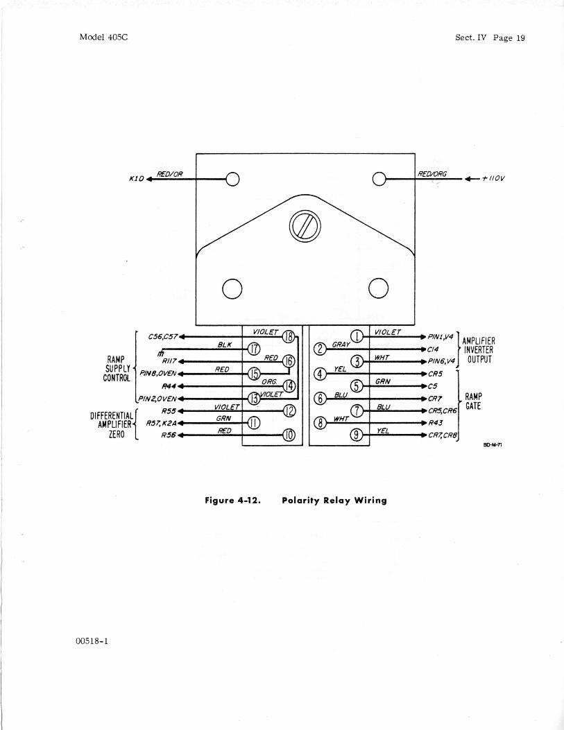
Figure 4-12. Polarity Relay Wiring
00518-1
Sect.IV Page 20 Model 405C
P301A R301 J301 1.2 M
R 3 0 3 41.7K
R 3 0 4 6000
R305 6000
R310 1M* I
47
P301B
39
40 L
4 1
42 2 - - 43
R314 10K
+300 V
F
T N
L
COPYRIGHT 1959 BY HEWLEII-PACKARD COMPANY
This drawing i s intended for tho operation and maintenance of Howlett-Pockard equip- ment and is not to be used otherwise or reproduced without written consent of tho Hewlett-Packard Company. 4 0 5 A - S X - 2 4 3
Figure 4-13. 405A-95C Digital Recorder Adapter
00518- 2

Model 40%
'@Stock No.
405A-65B
3140-0010
3160-0012
0170-0041
0170-0022
Sect.V Page 1
TQ* RS*
1 1
1 1
1 1
2 1
4 1
SECT10
5-1 I N T R O D U C T I O N This section contains information for ordering re- placement parts for the 405C Automatic DC Digital Voltmeter.
5-2 TABLE OF REPLACEABLE PARTS
Table 5- 1 lists replaceable parts in alpha-numerical order of their reference designators. A t the end of the table a r e listed miscellaneous items such a s knobs which have no assigned reference designators. Table 5-2, Digital RecorderAdaptor(hp stock no. 405A-95C).
Detailed information on a part used more than once in theinstrument is listed opposite the first reference designator applying to the part to appear i n the table. Other reference designators applying to the same part reference the initial designator. The detailed information includes the following:
1) Full description of the part.
2) Manufacturer of the part in a five-digit code -- see list of manufacturers in appendix.
3) Total quantity used in the instrument (TQ column).
4) Recommended spare quantity for complete mainten- ance during one year of isolated service (RS column).
R E P L A C E A B L E P A R T S
5-3 ORDERING I N F O R M A T I O N
To order a replacement part, address order or in- quiry either to your authorized Hewlett-Packard sales office o r to
CUSTOMER SERVICE Hewlett-Packard Company 395 Page Mill Road Palo Alto, California
or , in western Europe, to Hewlett-Packard S. A. Rue du Vieux Billard No. 1 Geneva, Switzerland
Specify the following information on a part: 1) Model and serial number of the instrument. Be sure to include the three-digit serial .prefix.
2) ($3 stock number.
3) Circuit reference designator.
4) Description.
To order a part notlistedin table 5-1, give a complete description of the part including its function and lo- cation in the circuit.
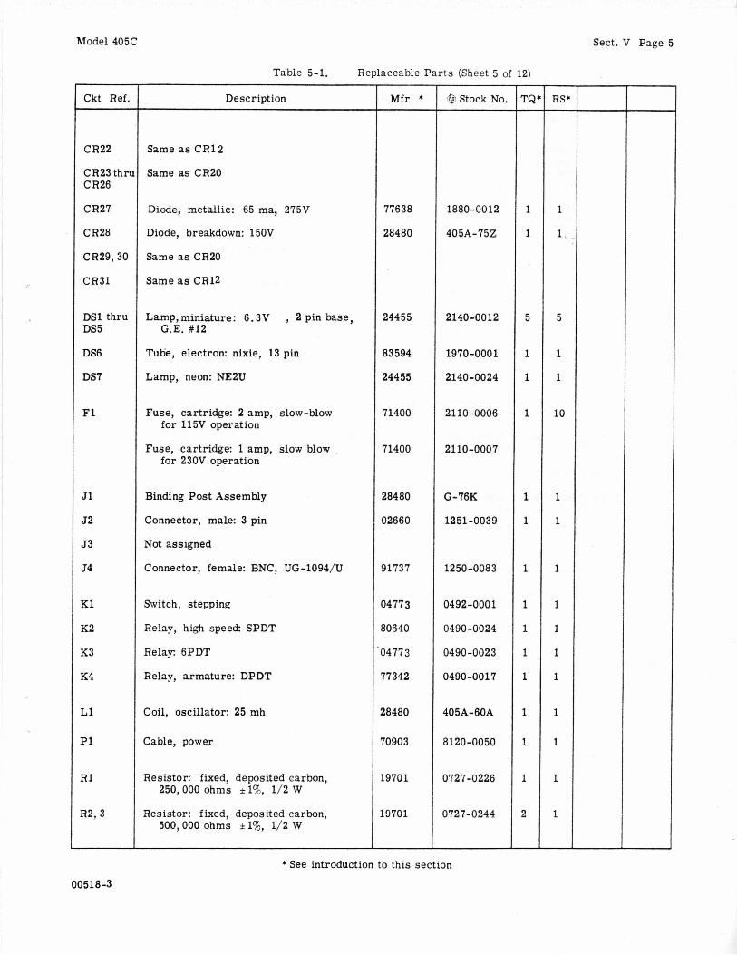
Table 5-1. Replaceable Par ts (Sheet 1 of 12)
Resistor Network consists of R4 thru R7
B1 Motor, AC: 2800 RPM
Blade, fan
c1 ,2 Capacitor: fixed, polystyrene, 0 .1 pf * 20%, 1000 vdcw
c3 Capacitor: fixed, mylar, 0 .1 pf *2Wo, 600 VdCW
Mfr *
* See introduction to th i s section
005 1 a- 3
Sect. V Page 2
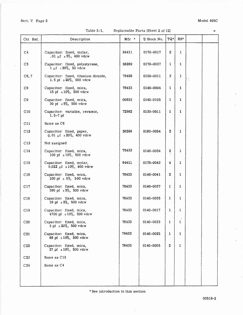
Table 5-1. Replaceable Par t s (Sheet 2 of 12)
Model 405C
w
Ckt Ref.
c 4
c 5
C6,7
C8
c 9
c10
c11
c12
C13
C 14
C15
C 16
C17
C 18
c19
c20
c 2 1
c22
C23
C 24
Description
Capacitor: fixed, mylar, .01 pf i5%, 400 vdcw
Capacitor: fixed, polystyrene, 1 pf i 20%, 50 vdcw
Capacitor: fixed, titanium dioxide, 1.5 pf *20%, 500 vdcw
Capacitor: fixed, mica, 15 pf *lo%, 500 vdcw
Capacitor: fixed, mica, 30 pf i5%, 500 vdcw
Capacitor: variable, ceramic, 1.5-7 pf
Same as C6
Capacitor: fixed, paper, 0.01 pf i 20%, 400 vdcw
Not assigned
Capacitor: fixed, mica, 100 pf i lOq l , , 500 vdcw
Capacitor: fixed, mylar, 0.022 pf ilW0, 400 vdcw
Capacitor: fixed, mica, 100 pf i 5o/c, 500 vdcw
Capacitor: fixed, mica, 390 pf i50/0, 500 vdcw
Capacitor: fixed, mica, 39 pf i 5 8 , 500 vdcw
Capacitor: fixed, mica, 4700 pf i loO/o, 500 vdcw
Capacitor: fixed, mica, 5 pf *20%, 500 vdcw
Capacitor: fixed, mica, 68 pf i 1 6 , 500 vdcw
capacitor: fixed, mica, 27 pf ilWo, 500 VdCW
Same as C15
Same as C4
Mfr *
84411
56289
78488
76433
00853
72982
56289
76433
84411
76433
76433
76433
76433
76433
76433
76433
@ Stock No.
0170-0017
0170-0037
0150-0011
0140-0004
0140-0105
0130-0011
0160-0054
0140-0054
0170-0043
0140-0041
0140-0037
0140-0035
0140-0017
0140-0033
0140-0025
0140-0005
- rQ -
2
1
3
1
1
1
2
2
4
2
1
1
1
1
1
2
-
R S - 1
1
1
1
1
1
1
1
1
1
1
1
1
1
1
1
* See introduction to this section
00518-2
Model 405C Sect. V Page 3
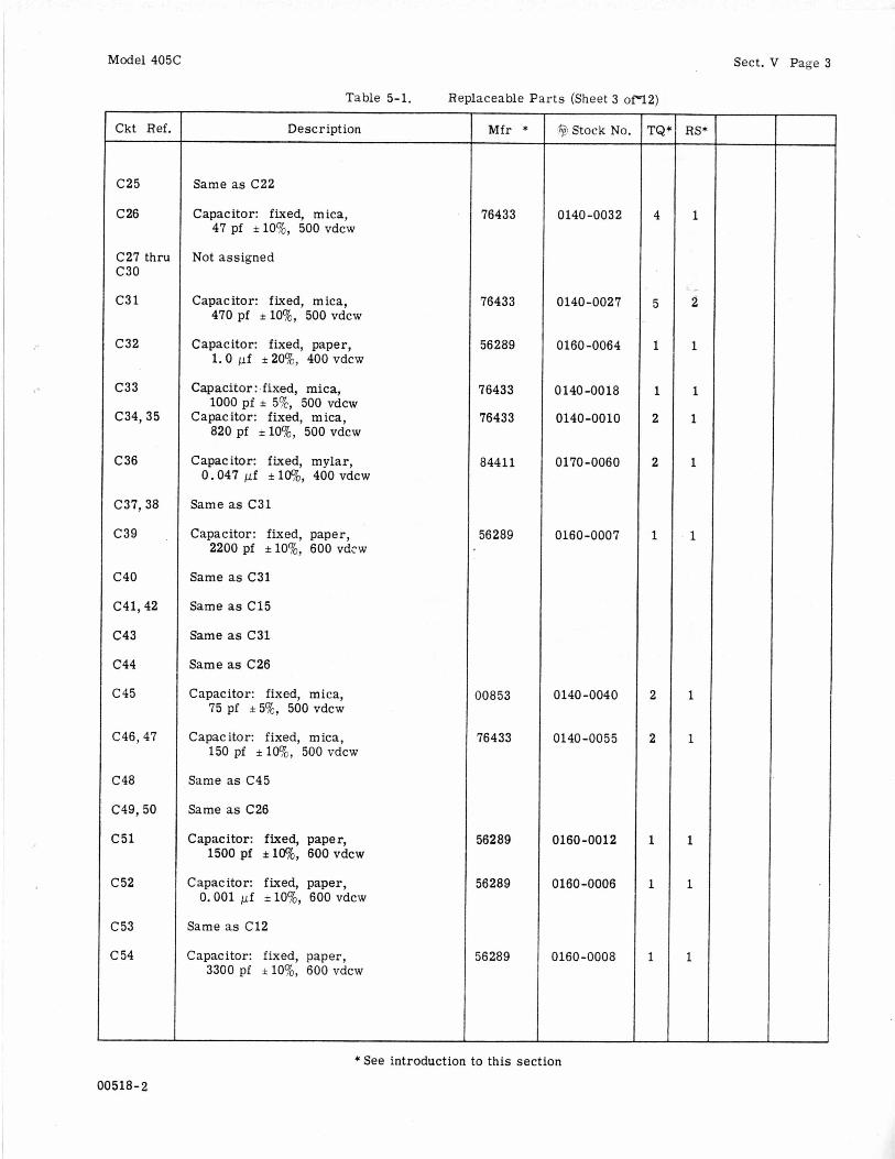
Table 5-1. Replaceable Par t s (Sheet 3 ofY2)
I
I .
Ckt Ref,
C25
C 26
C27 thru C30
C3 1
C32
c33
c34,35
C 36
C37,38
c39
C40
C41,42
c43
c44
c45
C46,47
C48
C49,50
C51
C 52
c 53
c 54
00518- 2
Description
Same as C22
Capacitor: fixed, mica, 47 pf *lo%, 500 vdcw
Not assigned
Capacitor: fixed, mica, 470pf *lo%, 500vdcw
Capacitor: fixed, paper, 1.0 pf i 20%, 400 vdcw
Capacitor: .fixed, mica,
Capacitor: fixed, mica, 1000 pf i 5o/c, 500 vdcw
820 pf *lo%, 500 vdcw
Capacitor: fixed, mylar, 0.047 pf i lo%, 400 vdcw
Same as C31
Capacitor: fixed, paper, 2200 pf *lo%, 600 vdcw
Same as C31
Same as C15
Same as C31
Same as C26
Capacitor: fixed, mica, 75 pf *5%, 500 vdcw
Capacitor: fixed, mica, 150 pf i lo?((, 500 vdcw
Same as C45
Same as C26
Capacitor: fixed, paper, 1500 pf *lo%, 600 vdcw
Zapacitor: fixed, paper, 0.001 pf *lo%, 600 vdcw
game as C12
3apacitor: fixed, paper, 3300 pf *lo%, 600 vdcw
Mfr *
76433
76433
56289
76433
76433
84411
56289
10853
76433
56289
56289
16289
9 Stock No.
0140-0032
0140-0027
0160-0064
0140-0018
0140-0010
0170-0060
0160-0007
0140 -0040
0140 -0055
0160-0012
0160-0006
0160-0008
* See introduction to this section
- TQ -
4
5
1
1
2
2
1
2
2
1
1
1
-
1
2
1
1
1
1
1
1
1
1
1
1
-
Sect. V Page 4 Model 405C
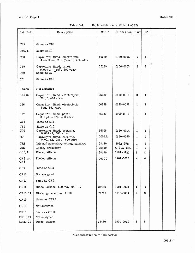
Table 5-1. Replaceable Par t s (Sheet 4 of 12)
Ckt Ref.
c55
C56,57
C58
c59
C60
C61
C62,63
C64,65
C66
C67
C68 C69 C70
C71
CR1 CR2 CR3,4
CR5 thru CR8
CR9
CRlO
CRl l
CR12
CR13,14
CR15
CR16
CR17 CR18, I 9 CR20,21
~~
Description
Same as C36
Same as C3
Capacitor: f ixed, electrolytic, 4 sections, 20 pf/sect. , 450 vdcw
Capacitor: fixed, paper,
Same as C3 0.047 pf, +100/0, 600 vdcw -
Same as C59
Not assigned
Capacitor: fixed, electrolytic,
Capacitor: fixed, electrolytic,
Capacitor: fixed, paper,
Same as C14 Same as C16 Capacitor: fixed, ceramic,
0.005 pf, 500 vdcw Capacitor: fixed ceramic,
0.001 pf, GdV, 600 vdcw Internal secondary voltage standard Diode, breakdown Diode, silicon
Diode, silicon
20 pf, 450 vdcw
8 pf, 350 vdcw
0.1 pf flog, 400 vdcw
Same as CR3
Not assigned
Same as CR3
Diode, silicon: 500 ma, 600 PIV
Diode, germanium : 1N90
Same as CR12
Not assigned
Same as CR12
Not assigned Diode, silicon
M f r *
56289
56289
56289
56289
56289
96095
OOORR
28480 28480 28480
ooocc
18480
73293
28480
$3 Stock No.
0180-0025
01 60-0005
0180-0011
0180-0038
0160-0013
0 1 4 50-001
0150-0050
405A-95D G- 31A- 18A 1901-00 25
1901-0023
1901-0028
1910-0004
1901-00 29
- TQ2 -
1
2
2
1
1
1
1
1 1 4
4
5
2
8
-
RS* -
1
2
1
1
1
1
1
1 1 4
4
5
2
8
- * See introduction to this section
005183
Model 405C
Table 5-1. Replaceable Parts (Sheet 5 of 12)
Sect. V Page 5
Ckt Ref.
CR22
CR23 thp CR26
CR27
CR28
CR29,30
CR31
DS1 thru DS5
DS6
DS7
F1
51
52
53
54
K1
K2
K3
K4
L1
P1
R 1
R2,3
Description
Same as CR12
Same as CR20
Diode, metallic: 65 ma, 275V
Diode, breakdown: 150V
Same as CR20
Same as CR12
Lamp,miniature: 6.3V , 2 Pin base, G.E. #12
Tu%, electron: nixie, 13 pin
Lamp, neon: NE2U
Fuse, cartridge: 2 amp, slow-blow for 115V operation
Fuse, cartridge: 1 amp, slow blow for 230V operation
Binding Post Assembly
Connector, male: 3 pin
Not assigned
Connector, female: BNC, UG-l094/U
Switch, stepping
Relay, high speed SPDT
Relay: 6PDT
Relay, armature: DPDT
Coil, oscillator: 25 mh
Cable, power
Resistor: fixed, deposited carbon, 250,000 ohms * 1%, 1/2 W
Resistor: fixed, deposited carbon, 500,000 ohms 1%, 1/2 W
M f r *
77638
28480
244 5 5
83 594
24455
71400
71400
28480
02660
91737
34773
30640
14773
77342
18480
70903
19701
19701
Stock No.
1880-0012
405A-75 2
2140-0012
1970-0001
2140-0024
2110-0006
2110-0007
G-76K
1251-0039
1250-0083
0492-0001
0490-0024
0490-0023
0490-0017
405A-60A
8120-0050
0727-0226
0727-0244
- TQ -
1
1
5
1
1
1
1
1
1
1
1
1
1
1
1
1
2
RS+ -
1
1
5
1
1
10
1
1
1
1
1
1
1
1
1
1
1
- * See introduction to this section
00518-3
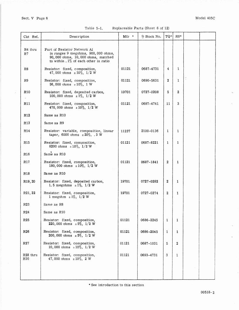
Sect. V Page 6 Model 405C
Ckt Ref.
R4 thru R7
R8
R9
R10
R11
R12
R13
R14
R15
R16
R17
R18
R19,20
R21,22
R23
R24
R25
R26
R27
R28 thru R30
Table 5-1. Replaceable Par t s (Sheet 6 of 12)
Description
Part of Resistor Network A1 in ranges 9 megohms, 900,000 ohms, 90,000 ohms, 10,000 ohms, matched to within . 1% of each other in ratio
Resistor: fixed, composition, 47,000 ohms i lo%, 1/2 W
Resistor: fixed, composition, 56,000 ohms +lWo, 1 W
Resistor: fixed, deposited carbon, 100,000 ohms * 1%, 1/2 W
Resistor: fixed, composition, 470,000 ohms i lo%, 1/2 W
Same as R10
Same as R9
Resistor: variable, composition, linear taper, 6000 ohms *2W& . 3 W
Resistor: fixed, composition, 8200 ohms *lo%, 1/2 W
Sam: as RIO
Resistor: fixed, composition, 180,000 ohms *lo%, 1/2 W
Same as R10
Resistor: fixed, deposited carbon, 1.5 megohms * 1%, 1/2 W
Resistor: fixed, composition, 1 megohm *1%, 1/2 W
Same as R8
Same as R10
Resistor: fixed, composition, 220,000 ohms i50/0, 1/2 W
Resistor: fixed, composition, 200,000 ohms * 50/0, 1/2 W
Resistor: fixed, composition, 10,000 ohms *lo%, 1/2 W
Resistor: fixed, composition, 47,000 ohms *lo%, 2 W
Mfr *
01121
01 121
19701
01121
11237
01121
01121
19701
19701
01121
01121
01121
01121
'@ Stock No.
0687-4731
0690-5631
0727-0208
06 87 -4 74 1
2100-0136
0687-8221
0687- 1841
0727-0282
0727-0274
0686-2245
0686 -2045
0687-1031
0693-473 1
- rQ -
4
2
5
11
1
1
2
2
2
1
1
5
3
-
- RS*
1
1
2
3
1
1
1
1
1
1
1
2
1
- * See introduction to this section
00518- 2
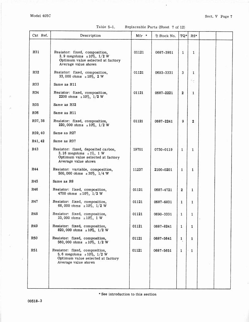
Model 405C
~~
Ckt Ref
R3 1
R32
R33
R34
R35
R36
R37,38
R39,40
R41,42
R43
R44
R45
R46
R47
R48
R49
R50
R51
Table 5-1. Replaceable Par ts (Sheet 7 of 12)
Description
Resistor: fixed, composition, 3.9 megohms *lo’%, 1/2 W Optimum value selected at factory Average value shown
Resistor: fixed, composition, 33,000 ohms *lo%, 2 W
Same as R11
Resistor: fixed, composition, 2200 ohms *lo%, 1/2 W
Same as R32
Same as R11
Resistor: fixed, composition,
Same a s R27
Same as R37
Resistor: fixed, deposited carbon,
220,000 ohms +lo%, 1/2 W
3.16 megohms *l%, 1 W Optimum value selected at factory Average value shown
Resistor: variable, composition,
Same as R8
Resistor: fixed, composition, 4700 ohms *lWc, 1/2 W
Resistor: fixed, composition, 68,000 ohms *lWo, 1/2 W
Resistor: fixed, composition, 33,000 ohms +lWo, 1 W
Resistor: fixed, composition, 820,000 ohms *lo%, 1/2 W
560,000 ohms *lo’%, 1/2 W
5.6 megohms i lo%, 1/2 W Optimum value selected at factory Average value shown
500,000 ohms i 30%, 1/4 W
Resistor: fixed, composition,
Resistor: fixed, composition,
M f r *
01121
01121
01 121
01121
19701
11237
01121
D1121
31121
11121
11121
11121
,@ Stock No.
0687-3951
0693 -333 1
0687-2221
0687-2241
0730-0119
2100-020 1
0687-4721
0687-6831
0690-3331
0687-8241
0687-5641
0687-5651
1
3
2
9
1
1
2
1
- RS, -
1
1
1
2
1
1
1
1
1
1
1
1
-
Sect. V Page 7
* See introduction to this section
00518-3

Sect. V Page 8 Model 405C
Table 5-1. Replaceable Par ts (Sheet 8 of 12)
Ckt Ref.
R52
R53
R54
R55
R56
R57
R58
R59
R60
R6 1
R6 2
R6 3
R64
R6 5
R66
R67
R68
R69
Description
Resistor: fixed, composition, 18,000 ohms i lo%, 2 W
Resistor: fixed, composition, 150,000 ohms *lo%, 1/2 W
Resistor: fixed, composition, 2700 ohms il09',, 1/2 W
Resistor: fixed, composition, 8.2 megohms i lo%, 1/2 W
Resistor: fixed, compos ition, 12 megohms *lo%, 1/2 W
Resistor: fixed, composition, 33 ohms *lo%, 1/2 W
Same as R17
Same as R11
Resistor: fixed, composition, 100,000 ohms i lo%, 1/2 W Optimum value selected at factory Average value shown
Resistor: fixed, composition, 270,000 ohms ,lo%, 1/2 W Optimum value selected at factory Average value shown
Same as R27
Same as R11
Resistor: fixed, composition, 100 ohms i lo%, 1/2 W
Resistor: variable, composition, linear taper, 10 megohms *30% includes S4. SPDT switch
Same as R46
Resistor: fixed, composition, 330,000 ohms i lo%, 1/2 W
Resistor: fixed, composition, 9.1 megohms i 50/0, 1/2 W Optimum value selected at factory Average value shown
Resistor: fixed, composition, 100,000 ohms i lWo, 1/2 W
Mfr *
01121
01121
01121
01121
01121
01121
01121
01121
01121
11237
01121
01121
01121
~~
'@ Stock No.
0693- 183 1
0687- 154 1
06 87 -2 72 1
06 8 7 -82 5 1
0687-1261
0687-3301
0687 - 104 1
0687-2741
0687-1011
2100-0152
0687-3341
0686-915 5
0687-1041
- I'Q' - 3
4
2
1
1
1
1
1 .
1
1
3
1
8
-
RS* - 1
1
1
1
1
1
1
1
1
1
1
1
2
* See introduction to this section 00518-3
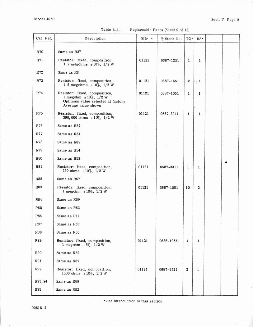
Model 405C Sect. V Page 9
Ckt Ref.
R70
R71
R72
R73
R74
R75
R76
R77
R78
R79
R80
R8 1
R82
R83
R84
R85
R86
R87
R88
R89
R90
R91
R92
R93,94
R95
Table 5-1. Replaceable Par ts (Sheet 9 of 12)
Description
Same as R27
Resistor: fixed, composition, 1.2 megohms i lo%, 1/2 W
Same as R8
Resistor: fixed, composition, 1.5 megohms i lw~, 1/2 W
Resistor: fixed, composition, 1 megohm *lo%, 1/2 W Optimum value selected a t factory Average value shown
Resistor: fixed, composition, 390,000 ohms &lo%, 1/2 W
Same as R32
Same as R34
Same as R69
Same as R54
Same as R53
Resistor: fixed, composition, 330 ohms *lo%, 1/2 W
Same as R67
Resistor: f ixed, composition, 1 megohm i l O % , 1/2 W
Same as R69
Same as R83
Same as R11
Same as R37
Same as R53
Resistor: fked, composition, 1 megohm +5%, 1/2 W
Same as R52
Same as R67
Resistor: fixed, composition, 1500 ohms +lo%, 1/2 W
Same as R89
Same as R52
Mfr *
01121
01121
01121
01121
01121
01121
01121
01121
'@ Stock No.
06 87 - 12 5 1
0687-1551
0687-1051
0687-3941
0687-3311
0687-1051
0686-1055
0687-1 521
* See introduction to this section
00518- 2
- rQ -
1
2
1
1
1
L O
4
2
-
- RS*
1
- 1
1
1
1
2
1
1

Sect. V Page 10 Model 405C
Table 5-1. Replaceable Par ts (Sheet 10 of 12)
Ckt Ref.
R96
R97
R98
R99
RlOO
RlOl
R102
R103 thru R105
R106
R107,108
R109,110
R l l l
R112
R113
R114
R115
R116
R117
R118 thru R121
R122
R123,124
R125
R126
R127
R128
Description
Same as R89
Same as R53
Same as R92
Same as R37
Same as R11
Same as R83
Same as R69
Same as R83
Resistor: fixed, composition, 2.2 megohms i IO%, 1/2 W
Same as R69
Same as R37
Same as R11
Same as R83
Resistor: fixed, composition, 2.7 megohms *lo%, 1/2 W
Same as R69
Same as R37
Resistor: fixed, composition, 680,000 ohms +50/0, 1/2 W
Resistor: fixed, composition, 750,000 ohms * 5%, 1/2 W
Not assigned
Same as E273
Same as R11
Resistor: fixed, composition, 39,000 ohms i lo%, 1/2 W
Resistor: fixed, wirewound, 2000 ohms *50/0, 10 W Optimum value selected at factory Average value shown
Resistor: fixed, wirewound, 4000 ohms i5%, 10 W
Resistor: fixed, composition, 510,000 ohms * 5%, 1/2 W
M f r *
01121
01121
01121
01121
01121
35434
75042
01121
$+ Stock No.
06 8 7- 225 1
0687-2751
0686-6845
0686 -754 5
0687-3931
0816 -0012
081 5-0003
0686 -5145
1
1
1
1
1
1
1
1
-
- RS* -
1
1
1
1
1
1
1
1
- * See introduction to this section
00518-1
Model 405C
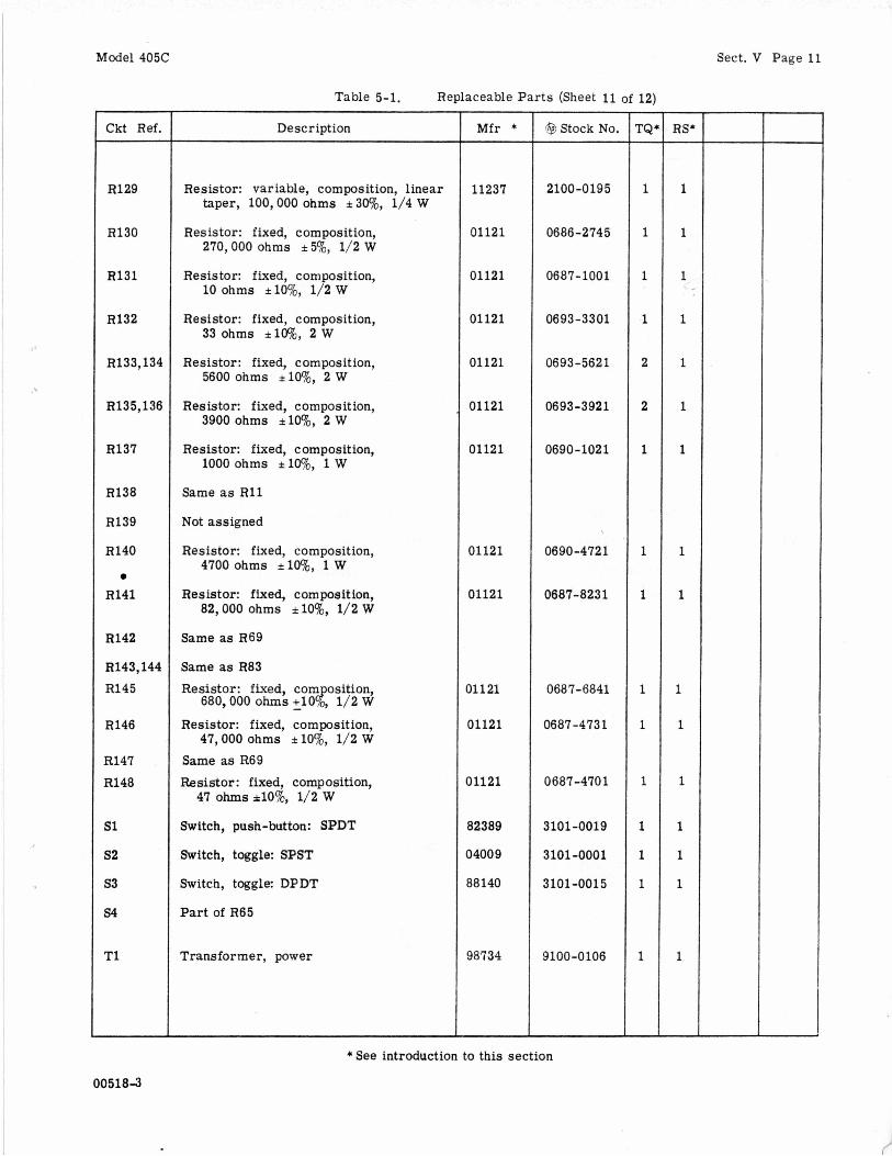
Table 5-1. Replaceable Par ts (Sheet 11 of 12)
Sect. V Page 11
Ckt Ref.
R129
R130
R131
R132
R133,134
R135,136
R137
R138
R139
R140
R141
R142
R143,144 R145
R146
R147 R148
s1 52
s 3
s4
T1
Description
taper, 100,000 ohms -i 30%, Resistor: variable, composition, linear
i/4 w Resistor: fixed, composition,
270,000 ohms i 5%, 1/2 W
Resistor: fixed, composition, 10 ohms *lo%, 1/2 W
Resistor: fixed, composition, 33 ohms *lo%, 2 W
Resistor: fixed, composition, 5600 ohms *lo%, 2 W
Resistor: fixed, composition, 3900 ohms ilW0, 2 W
Resistor: fixed, composition, 1000 ohms ilW0, 1 W
Same as R11
Not assigned
Resistor: fixed, composition, 4700 ohms ~ l o o / o , 1 W
Resistor: fixed, composition, 82,000 ohms f lo%, 1/2 W
Same as R69
Same as R83 Resistor: fixed, com osition,
680,000 ohms +lo{ - 1/2 W
Resistor: fixed, composition, 47,000 ohms i lo%, 1/2 W
Same as R69 Resistor: fixed, composition,
47 ohms *lo%, 1/2 w Switch, push-button: SPDT
Switch, toggle: SPST
Switch, toggle: DPDT
Part of R65
Transformer, power
Mfr *
11237
01121
01121
01121
01121
01121
01121
01121
01121
01121
01121
01121
82389
04009
88140
98734
@ Stock No.
2100-0195
0686-2745
0687-1001
06 93 -3 3 01
0693-5621
0693-3921
0690-1021
0690-472 1
0687-8231
0687-6841
0687-473 1
0687 -470 1
3101 -0019
3101-0001
3101-001 5
9100-0106
* See introduction to th i s section
005183
- rQ -
1
1
1
-1
2
2
1
1
1
1
1
1
1
1
1
1
-
r54 -
1
1
1
1
1
1
1
1
1
1
1
1
1
1
1
1
-
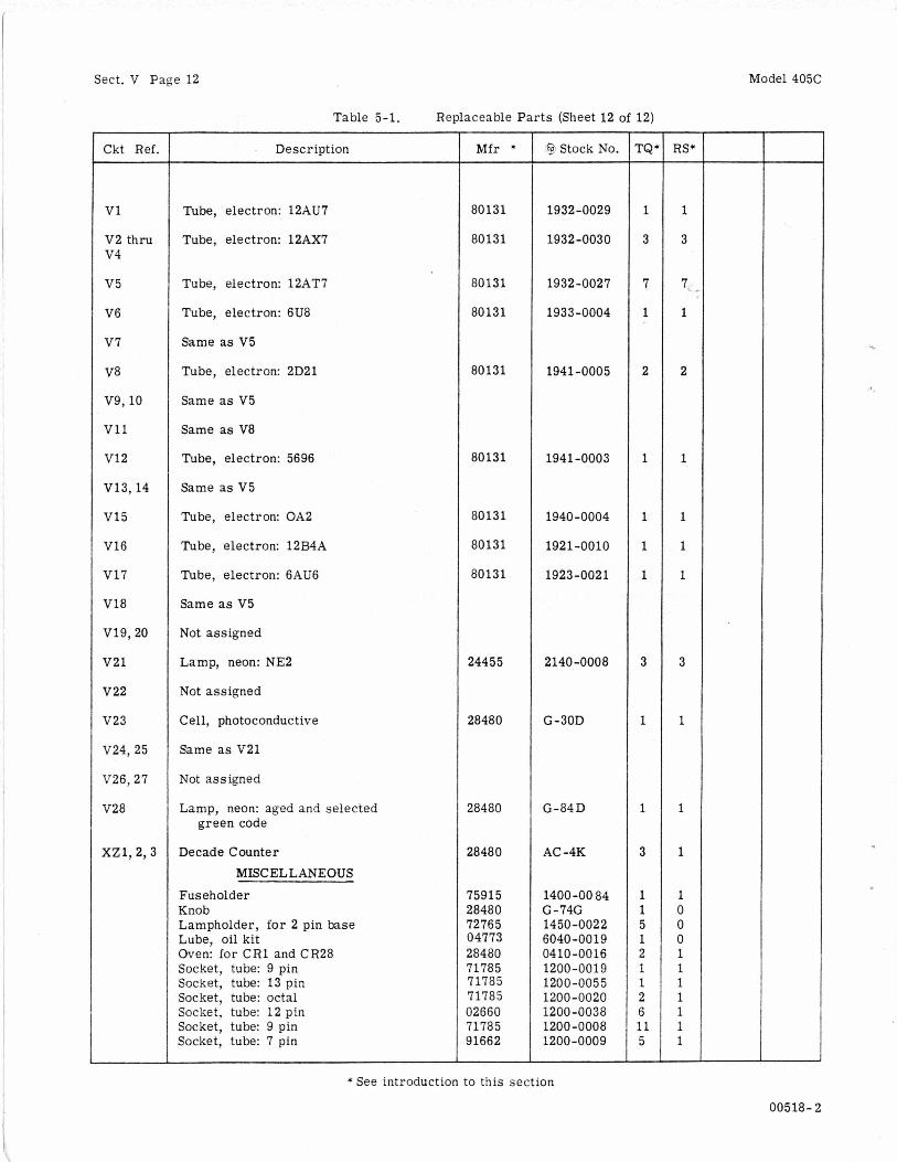
Sect. V Page 12
Table 5-1. Replaceable Parts (Sheet 12 of 12)
Ckt Ref.
v1 V2 thru v 4
v 5
V6
v 7
V8
V9,lO
v11
v12
V13,14
V15
V16
V17
V18
v19,20
v21
v22
V23
V24, 25
V26,27
V28
xz1 ,2 ,3
Description
Tube, electron: 12AU7
Tube, electron: 12AX7
Tube, electron: 12AT7
Tube, electron: 6U8
Same as V5
Tube, electron: 2D21
Same as V5
Same as V8
Tube, electron: 5696
Same as V5
Tube, electron: OA2
Tube, electron: 12B4A
Tube, electron: 6AU6
Same as V5
Not assigned
Lamp, neon: NE2
Not assigned
Cell, photoconductive
Same as V21
Not assigned
Lamp, neon: aged and selected green code
Decade Counter MISCELLANEOUS
Fuseholder Knob Lampholder, for 2 pin base Lube, oil kit Oven: for C R 1 and CR28 Socket, tube: 9 pin Socket, tube: 13 pin Socket, tube: octal Socket, tube: 12 pin Socket, tube: 9 pin Socket, tube: 7 pin
M f r *
80131
80131
80131
80131
80131
80131
80131
80131
80131
24455
28480
28480
28480
75915 28480 72765 04773 28480 71785 71785 71785 02660 71785 91662
’?$ Stock No.
1932-0029
1932-0030
1932-0027
1933-0004
1941 -0005
1941-0003
1940-0004
1921-0010
1923-0021
2140-0008
G-30D
G-84D
AC -4K
1400-00 84 G-74G 1450-0022 6040-0019 04 10 -0016 1200-0019 1200 -005 5 1200-0020 1200-0038 1200-0008 1200-0009
- rQ4 -
1
3
7
1
2
1
1
1
1
3
1
1
3
1 1 5 1 2 1 1 2 6 11 5 -
RS* -
1
3
7
1
2
1
1
1
1
3
1
1
1
1 0 0 0 1 1 1 1 1 1 1 -
Model 405C
* See introduction to this section
00518- 2

Model 405C
Table 5-2. Digital Recorder Adapter 405A-95C
Ckt Ref.
CR1 thrt CR300
CR301
J1 thru 5300
5301
P1 thru P300
P301A/E
R1 thru R300
R301
R30 2
R303
R304 thr R306
R307
R30 8
R309
R3 10
R311 thr R313
€7314
Description
Not assigned
Diode, zener: 18V
Not assigned
Connector, female: 19 pin
Not assigned
Connector, male: 50 pin miniature
Not assigned
Resistor: fixed, deposited carbon, 1.2 megohms A%, 1/2 W
linear taper, 10,000 ohms f 20%, 1/4W
41,700 ohms i 1%, 1/2 W
6000 ohms f 1%, 1/2 W
37.4K ohms i 1%, 1/2 W
Resistor: variable, composition,
Resistor: fixed, deposited carbon,
Resistor: fixed, deposited carbon,
Resistor: fixed, deposited carbon,
Same as R302
Resistor: fixed, composition, 56,000 ohms f lo%, 1/2 W Optimum value selected at factory; average value shown
Resistor: fixed, deposited carbon, 1 megohm i I%, 1/2 W
Resistor: fixed, deposited carbon, 1.23 megohms i l%, 1 W
Resistor: fixed, composition, 10,000 ohms f lo%, 2 w
M f r *
28480
71468
02660
19701
11237
19701
19701
19701
01121
1970 1
19701
01121
’@ Stock No.
G-29A-18
12 5 1 -0056
1251 -0099
0727-0280
2100 -0092
0727-0189
0727-0140
0727-0187
0687-5631
0727-0276
0730-0108
0693 -1031
* See introduction to this section
00518-2
- rQi -
1
1
2
1
2
1
3
1
1
1
3
1
-
- RS+
1
1
1
1
1
1
1
1
1
1
1
1
-
Sect. V Page 13
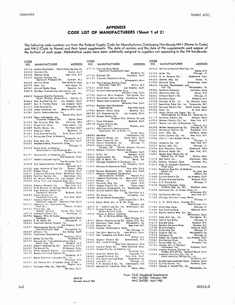
Appendix
APPENDIX CODE LIST .OF MANUFACTURERS (Sheet 1 of 2)
Model 405C
The following code numbers are from the Federal Supply Code for Manufacturers Cataloging Handbooks H4-1 (Name t o Code) and H4-2 (Code t o Name) and their latest sup lements. The date of revision and the date of the supplements used appear at the bottom of each page. Alphabetical codes [ave been arbitrarily assigned to suppliers not appearing in the H 4 handbooks.
CODE NO. MANUFACTURER ADDRESS
0 0 1 3 6 McCoy Electronics Mount Holly Springs, Pa. 0 0 3 3 4 Humidial Co. Colton. Calif. 0 0 3 3 5 Westrex Corp. New York, N.Y. 0 0 3 7 3 Garlock Packing Co..
Electronic Products Div. Camden, N.J. 0 0 6 5 6 Aerovor Corp. New Bedford, Mass. 0 0 7 7 9 Amp. Inc. Harrisburg. Pa. 0 0 7 8 1 Aircraft Radio Corp. Boonton. N.J. 0 0 8 1 5 Northern Enqineering Laboratories, Inc.
Burlington. Wis. 0 0 8 5 3 Sangamo Electric Company.
Ordill Division (Capacitors) Marion, Ill. 0 0 8 6 6 Goe Enqineering Co. Lor Anqeles, Calif. 0 0 8 9 1 Carl E. Holmes Corp. 10s Anqelcs. Calif. 0 1 1 2 1 Allen Bradley Co. Milwaukee. Wis. 0 1 2 5 5 Litton Industries. Inc. Beverly Hills. Calif. 0 1 2 8 1 Pacific Semiconductors. Inc.
Culver City. Calif. 0 1 2 9 5 Teras Instruments, Inc.
Transistor Products Div. Dallas. Texas 0 1 3 4 9 The Alliance Mfq. Co. Alliance, Ohio 0 1 5 6 1 Chassi-Trdk Corp. Indianapolis. Ind. 0 1 5 8 9 Pacific Relays. Inc. Van NUIS. Calif. 0 1 9 3 0 Amerock Corm Rockford. Ill. 0 1 9 6 1 Pulse Engineering Co. Santa Clara, Calif. 0 2 1 1 4 Ferrorrube Corp. of America
Sauqerties. N.Y. 0 2 286 Cole Mfq. Co. Palo Alto, Calif. 0 2 6 6 0 AmphenoCBorg Electronics Corp.
Chicago. Ill. 0 2 7 3 5 Radio Corp. of America
Somerville. N.J.
O ld Savbrook. Conn.
Semiconductor and Materials Div.
0 2 7 11 Vocaline Co. of America. Inc.
0 2 7 7 7 Hopkins Engineering Co. San Fernando. Calif.
0 3 5 0 8 G.E. Semiconductor Products Dept. Syracuse. N.Y.
0 3705 Apex Machine 6 Tool Co. Dayton. Ohio 0 3 7 9 7 Eldema Corp. E l Monte. Calif. 0 3 8 7 7 Transitton Electronic Corp. Wakefield. Mass. 0 3 8 8 8 Pvrofilm Resistor Co. Morristown. N.J. 0 3 9 5 4 Air Marine Motors. lnc. Lor Anqeles. Calif. 0 4 0 0 9 Arrow, Hdrt and Heqeman Elect. Co.
Hartford Con" 0 4 0 6 2 Elmenco Products Co. New York. N.Y. 0 4 2 2 2 Hi-Q Division of Aerovor Myrtle Beach. S.C. 0 4 2 9 8 Elqin National Watch Co..
Electronics Division Burbank. Calif. 0 4 4 0 4 Dymec Division of
Hcwlett-Parkard Co. Palo Alto, Calif. 0 4 6 5 1 Sylvania Electric Prods., Inc.
Electronic Tube Div. Mountain View, Calif. 0 4 7 1 J Motorola. Inc.. Semiconductor
Prod. Div. Phoenix, Arizona 0 4 7 3 2 Filtron Co.. Inc.
Western Division Culver City. Calif. 0 4 7 1 3 Automatic Electric Co. Northlake. 111 0 4 7 9 6 Sequoia Wire & Cable
Ccmpanv Redwood City. Calif. 0 4 8 7 0 P. M. Motor Co. Chicago 44. Ill. 0 5 0 0 b Twentieth Century Plastics, Inc.
Lor Angeles, Calif. 0 5 2 7 7 Westinqhouse Electric Corp.,
Semi-Conductor Dept. Younqwood. Pa. 0 5 3 4 7 Ullronir, Inc. San Mateo. Calif. 0 5 5 9 3 lllumitronic Engineering Co.
Sunnyvale, Calif. 0 5 6 2 4 Barber Colman Co. Rockford, 111. 0 5 7 2 9 Metropolitan Telecommunications Corp.,
Metro Cap. Div. Brooklyn. N.Y. 0 5 7 8 3 Stewart Engineering Co. Santa Crur, Calif. 0 6 0 0 4 The Bassick Co. Bridgeport. Conn. 0 6 1 3 6 Ward Leonard Electric Lor Anqeles. Calif. 0 6 1 7 5
Rochester, N.Y. 0 6 5 5 5
Penacook. N.H.
Bausch and Lomb Optical Co.
Beede Electrical Instrument Co.. Inc.
0 6 7 5 1
0 6 8 1 2
U.S. Semcor Div. of Nuclear Corp. of Am.
Torrinqton Mfq. Co.. West Div. Phoenix. Arir.
Van Nuvs. Calif.
CODE NO.
07115
0 7 1 2 6 0 7 1 3 7
0 7 1 3 8
07261 0 7 2 6 3
0 7 7 0 0 0 7 9 1 0 07T33
0 7 9 6 b
0 7 9 8 0 0 8 1 4 5 0 8 3 5 8
0 8 7 1 7 0 8 7 1 8
0 8 7 9 2
0 8 9 9 4 0 9 0 2 6 0 9 1 3 4 0 9 2 5 0 09569
1 0 2 1 4
10411 10646 11236 1 1 2 3 7
11312
1 1 534 11711
1 1 7 1 7 11870 l2b97 12859 14298 14655
15909 1 6 6 8 8
16758
18873 19315
19500
19701 20183 2 1 2 2 6 21520
21335 21964
24446 24455
24655 26462
26992 28480 33173 3 5 4 3 4 37942 39543
W15-30 Revised: March 1963
MANUFACTURER ADDRESS
Corning Glass Works
Bradford, Pa. Diqitran Co. Pasadena. Calif. Transistor Electronics Corp.
Minneapolis. Minn Westinghouse Electric Corp.
Electronic Tube Div. Elmira. N.Y. Avnet Corp. Lor Anqeles. Calif. Fairchild Semiconductor Cotp.
Mountain View. Calif. Technical Wire Products Sprinqfield, N.J. Continental Device Corp. Hawthorne, Calif. Rheem Semiconductor Corp.
Mountain View, Calif. Shocklev Semi-Conductor
La boratories Palo Alto, Calif. Boonton. N.J. Boonton Radio Corp.
U.S. Engineering Co. Lor Anqeles. Calif. Burgess Battery Co.
Niaqara Falls. Ontdrio. Canada Sloan Company Burbank. Calif. Cannon Electric Co.
Phoenix Div. Phoenix. Aril. CBS Electronics Semiconductor
Operations. Div. of C.B.S. Inc. Lowell, Mass.
Mel-Rain Indianapolis, Ind. Babcock Relays, Inc. Costa Mesa. Calif. Teras Capacitor Co. Houston, Teras Electro Assemblies. Inc. Chicago. Ill. Mallorv Battery Co. of
Canada, Ltd. Toronto, Ontario, Canada General Transistor Western Corp.
Los Anqeles, Calif. Ti-Tal, Inc. Berkeley. Calif. Carborundum Co. Niagara Falls, N.Y. CTS of Berm. Inc. Berne. Ind. Chicaqo Telephone of California, Inc.
So. Pasadena, Calif. Microwave Electronics Corp.
Palo Alto, Calif, Duncan Electronics, Inc. Santa Ana. Calif. General Instrument Corporation
Semiconductor Division Newark, N.J. Imperial Electronics, Inc. Buena Park. Calif. Melabs, Inc. Palo Alto, Calif. Clarostat Mlg. Co. Dover. N.H. Nippon Electric Co.. Ltd. Tokyo, Japan American Components, Inc. Conshocken. Pa. Cornell Dubilier Elec. Corp.
So. Plainfield. N.J. The Daven Co. Livingston. N.J. De Jur-Amsco Corporation
Long Island City I. N.Y. Delco Radio Div. of 6. M . Corp.
Kokomo. Ind. E. I. DuPont and Co.. Inc. Wilmington. Del. Eclipse Pioneer, Dir. of
Bendir Avidtior. Corp. Teterboro, N.J. Thomas A. Edison Industries,
Div. of McGraw-Edison Co.
Electronic Components Dept.
West Oranqe. N.J. Electra Manufacturing Co. Kansas City. Mo. Electronic Tube Corp. Philadelphia. Pa. Executive. Inc. New York. N.Y. Fanstetl Metallurgical Corp.
No. Chicago, 111. The Fafnir Bearing Co. New Britain. Conn. Fed. Telephone and Radio Corp.
Clifton, N.J. General Electric CO. Schenectady. N.Y. G.E., Lamp Division
N d a Park, Cleveland, Ohio General Radio Co. West Concord, Mass. Grobet File Co. of America. Inc.
Carlstadt. N.J. Hamilton Watch Co. Lancastar. Pa. Hewlett-Packard Co. Palo Alto, Calif. G.E. Recrivinq Tube Dept. Owensboro. Kv. Lectrohm inc. Chicaqo. Ill. P. R. Mallory 6 Co.. Inc. Indianapolis, Ind. Mechanical Industries Prod. Co.
Akron, Ohio
CODE NO. MANUFACTURER ADDRESS
4 0 9 2 0 Keen., N.H.
4 2 1 9 0 Muter Co. Chicago. 111. 4 3 9 9 0 C. A. Norqren Co. T Englewood. Colo. 4 4 6 5 5 Ohrnite Mfg. Co. Skokie. 111.
Cambridge. Mass. 4 7 9 0 4 Polaroid Corp. 4 8 6 2 0 Precision Thermom*ter and
Inst. Co. Philadelphia, Pa. 4 9 9 5 6 Raytheon Company Lerinqton, Mass.
Selma. N.C. 5 4 2 9 4 Shallcross Mfq. Co. 5 5 0 2 6 Simpson Electric Co. Chicaqo. Ill. 5 5 9 3 3 Sonotone Corp. Elmsford, N.Y. 5 5 9 3 8 Sorcnson & Co.. Inc. So. Norwalk. Conn. 5 6 1 3 7 Spaulding Fibre Co.. Inc. Tonawanda. N.Y. 5 6 2 8 9 Spraque Electric Co. North Adams. Mass. 5 9 4 4 6 Telex. Inc. St. Paul, Minn. 6 1 7 7.5 Union Switch and Signal. Div. of
Westinqhouse Air Brake Co. Swissvale. Pa. 6 2 1 1 9 Universal Electric Co. Owosso. Mich. 6 4 9 5 9 Western Electric Co.. Inc. New York. N.Y. 6 5 0 9 2 Weston Inst. Div. of Daystrom, Inc.
Newark, N.J. 6 6 2 9 5 Wittek Manufacturing Co. Chicago 23. 111. 6 6 3 4 6 Wollensak Optical Co. Rochester, N.Y. 70 2 7 6 Allen Mfq. Co. Hartford. Conn. 7 0 3 0 9 Allied Control Co., Inc. New York. N.Y. 7 0 4 8 5 Atlantic India Rubber Works, Inc.
Chicago. Ill. New York, N.Y. 7 0 5 6 3 Amperite Co.. Inc.
7090 3 Eelden Mfg. Co. Chicago. 111. 7 0 9 9 8 Bird Electronic Corp. Cleveland. Ohio 7 1 0 0 2 Birnbach Radio Co. Ueu York, N.Y. 7 1 0 4 1
Quincy. Mass. 7 12 18 Bud Radio Inc. Cleveland. Ohio 7 1 2 8 6 Camloc Fastener Corp. Paramus. N.J.
Miniature Precision Bearings. Inc.
Boston Gear Works Div. of Mtirrav Co. of Teras
7 1 3 1 3 Allen D. Cardwell Electronic
7 1 4 0 0 Bussmann Fuse Div. of McGraw-
7 14 5 0 CTS Corp.
Prod. Corp. Plainville. Conn.
Edison Co. St. Louis, Mo. Elkhart. Ind.
7 1 4 6 8 Cannon Electric Co. 10s Angeles, Calif. 7 1 4 7 1 Cinema Engineering Co. Burbank. Calif. 7 1 4 8 2 C. P. Clare & Co. Chicago, 111. 7 1 5 2 8 Stdnddrd-Thornsen Corp
Clifford Mfg. Co. Di;: Waltham, Mass. 7 1 5 9 0 Centralab Div. of Globe Union Inc.
Milwaukee, Wis. New York. N.Y. 7 1 7 0 0 The Cornish Wire Co.
7 1 7 4 4 Chicago Miniature Lamp Works
7 1 7 5 3 A. 0. Smith Corp.. Crowley Div. Chicago. 111.
West Orange. N.J. 7 1 7 8 5 Cinch Mfq. Corp. Chicago. Ill. 7 1 9 8 4 Dow Corning Corp. Midland. Mich. 7 2 1 3 6 Electro Motive Mfq. Co.. Inc.
Willimantic, Conn. 7 1 7 0 7 Cot0 Coil Co.. Inc. Providence, R.I . 7 2 3 5 4 John E. Fast 6 CO. Chicago. 111.
Brooklyn. N.Y. 7 2 6 1 9 Dialight Corp. 7 2 6 5 6 General Ceramics Corp. Keasbey. N.J. 7 2 7 5 8 Girard-Hopkins Oakland, Calif. 7 2 7 6 5 Drake Mfq. Co. Chicago, Ill. 7 2 8 2 5 Hugh H. Eby !nc. Philadelphia. Pa. 7 2 9 2 8 Gudeman Co. Chicago, Ill. 7 2 9 6 4 Robert M. Hadlev Co. Lo$ Anqeles. Calif. 7 2 9 8 2 Erie Resistor Corp. Erie, Pa.
Princeton, Ind. 7 3 0 6 1 Hansen Mfq. Co.. Inc. 7 3 1 3 8 Helipot Div. of Beckman
Instruments, Inc. Fullerton, Calif. 7 3 2 9 3 Huqhes Products Division of
Huqhes Aircraft Co. Newport Beach. Calif. 7 3 4 4 5 Amperer Electronic Co., Div. of . North American Phillips Co. Inc.
hicksville. N.Y. 7 3 5 0 6 Bradley Semiconductor Corp. Hamden, Conn. 7 3 5 5 9 Carlinq Electric, Inc. Hartford. Conn. 7 3 6 8 2 George K. Garrett Co.. Inc.
Philadalphia. Pa.
From: F.S.C. Handbook Supplements H4-1 DATED: February 1963 H4-2 DATED: April 1962
i-0
..
005 18-3
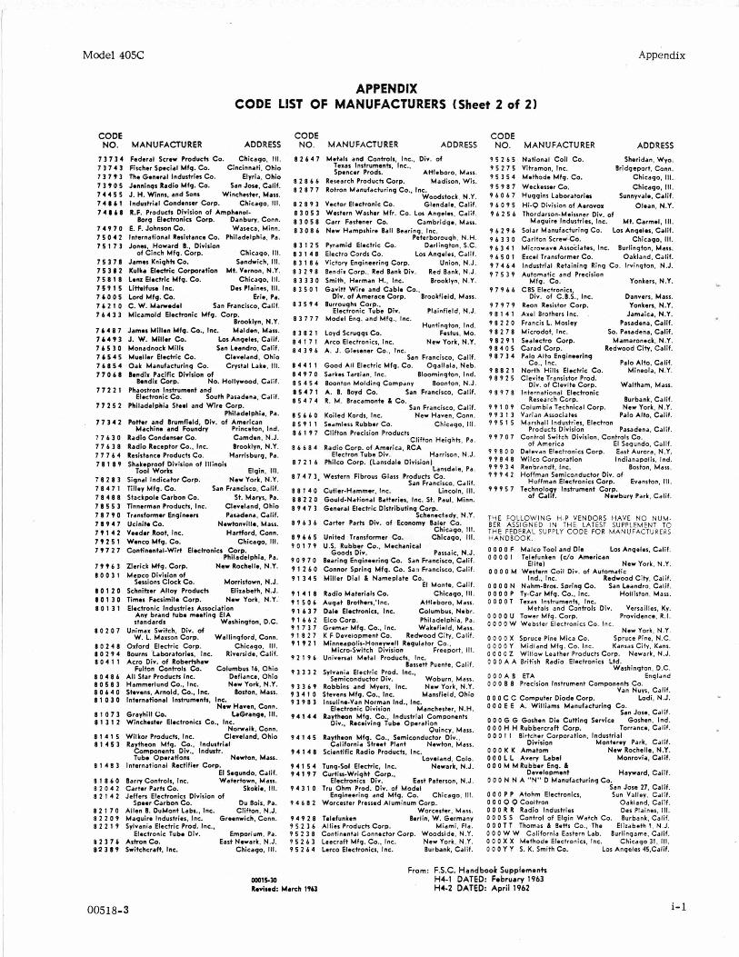
Model 405C
APPENDIX CODE LIST OF MANUFACTURERS (Sheet 2 of 2)
Appendix
Texas Instruments. Inc.. Spencer Prods. Attleboro. Mass.
8 2 8 6 6 Research Products Corp. Madison, Wis. 8 2 8 7 7 Rotron Manufacturing Co.. Inc.
Woodstock. N.Y. 8 2 8 9 3 Vector Electronic Co. Glendale. Calif. 8 3 0 5 3 Western Washer Mfr. Co. Lor Angeln, Calif. 8 3 0 5 8 Carr Fastener Co. Cambridge, Mass. 8 3 0 8 6 New Hampshire Ball Bearing. Inc.
Peterborough. N.H. 8 3 1 2 5 Pyramid Electric Co. Darlington. S.C. 8 3 1 4 8 Electro Cords Co. Lor Angeles. Calif. 8 3 1 8 6 Victory Engineering Corp. Union. N.J. 8 3 2 9 8 Bendir Corp., Red Bank Div. Red Bank. N.J. 8 3 1 3 0 Smith, Herman H.. Inc. Brooklyn. N.Y. 8 3 5 0 1 Gavitt Wire and Cable Co.,
Div. of Amerace Corp. Brookfield. Mass. 8 3 5 9 4 Burroughs Corp..
Electronic Tube Div. Plainfield. N.J. 8 3 7 7 7 Model Eng. and Mfg., Inc.
Huntington, Ind. 8 3 8 2 1 Loyd Scrugqs Co. Fcstus. Mo. 8 4 1 7 1 Arco Electronics, Inc. New York. N.Y.
CODE CODE CODE
7 3 7 3 4 Federal Screw Products Co. Chicago. 111. 8 2 6 4 7 Metals and Controls, Inc.. Div. of 9 5 2 6 5 National co i l co. 7 3 7 4 3 Fischer Special Mfq. Co. Cincinnati. Ohio 7 3 7 T 3 The General Industries Co. Elyria. Ohio 7 3 T 0 5 Jennings Radio Mfq. Co. Sin Jose. Calif. 7 4 4 5 5 J. H. Winns. and Sons Winchester. MJSS. 7 4 8 A 1 Industrial Condenser Corp. Chicago. 111. 7 4 0 6 8 R.F. Products Division of Amphmol-
Borg Electronics Corp. Danbury. Conn. 7 4 9 7 0 E. F. Johnson Co. Waseca. Minn. 7 5 0 4 2 International Resistance Co. Philadelphia. Pa. 7 5 1 7 3 Jonn, Howard 0.. Division
Chicago. 111. 7 5 3 7 8 James Knights Co. Sandwich. 111. 7 5 3 8 2 Kulka Electric Corporation MI. Vernon. N.Y. 7 5 8 1 8 Lenz Electric Mfg. Co. Chicago. 111. 7 5 9 1 5 Littelfuse Inc. Des Plaines. 111. 7 b 0 0 5 Lord Mfg. Co. Erie. Pa. 7 6 2 1 0 C. W. Marredel San Francisco. Calif. 7 6 4 3 3 Micamold Electronic Mfq. Corp.
Brooklyn. N.Y. 7 b 4 8 7 James Mlllen Mfg. Co.. Inc. Malden. Mass. 7 b 4 9 3 J. W. Miller Co. Lo5 Angeles. Calif. 7 b 5 3 0 Monadnock Mills San Ledndro. Calif. 7 1 5 4 5 Mueller Electric Co. Cleveland. Ohio 7 6 8 5 4 Oak Manufacturing Co. Crystal Lake. 111. 7 7 0 6 8 Bendix Pacific Division of
Bendix Corp. No. Hollywood. Calif. 7 7 2 2 1 Phaostron Instrument and
Electronic Co. South Pasadena. Calif. 7 7 2 5 2 Philadelphia Steel and Wire Corp.
Philadelphia. Pa. 7 7 3 4 2 P h r and Brumfield. Div. of American
Machine and Foundry Princeton, Ind. 7 7 6 3 0 Radio Condensor Co. Camden. N.J. 7 7 6 3 8 Radio Receptor Co.. Inc. Brooklyn. N.Y. 7 7 7 6 4 Resistance Products Co. Harrisburg, Pa. 7 8 1 8 9 Shakeproof Division of Illinois
Tool Works Elgin, 111. 7 8 2 8 3 Signal Indicator Corp. New York. N.Y. 7 8 4 7 1 Tilley Mfg. Co. Sdn Francisco, Calif. 7 8 4 B 8 Stackpole Carbon Co. St. Marys. Pa. 7 8 5 5 3 Tinnerman Products. Inc. Cleveland. Ohio 7 8 7 9 0 Transformer Engineers Pasadena. Calif. 7 8 9 4 7 Ucinite Co. Newtonrille, Mass. 7 T 1 4 2 Veeder Root. Inc. Hartford, Conn. 7 T 2 5 1 Wenco Mfg. Co. Chicago, Ill. 7 9 7 2 7 Continental-Wirt El.ctronlcs Corm
Philadelphia. Pa. 7 9 T 6 3 Zlerick Mfq. Corp. New Rochelle, N.Y. 8 0 0 3 1 M.DCO Division of
Sessions Clock Co. Morristown. N.J. 8 0 1 2 0 Schniher Alloy Products Elizabeth. N.J. 8 0 1 3 0 Times Facsimile Corp. New York. N.Y. 8 0 1 3 1 Electronic Industries Association
NO. MANUFACTURER ADDRESS NO. MANUFACTURER ADDRESS NO. MANUFACTURER ADDRESS
Sheridan. Wvo.
of Cinch Mfg. Corm
Any brand tube meeting EIA standards Washington. D.C.
8 0 2 0 7 Unimax Switch, Div. of W. L. Maxson Corp. Wallingford. Conn.
8 0 2 4 8 Oxford Electric Corp. Chicago. Ill. 8 0 2 9 4 Bourns Laboratories. Inc. Riverside. Calif. 8 0 4 1 1 Acro Div. of Robertshaw
Fulton Controls Co. Columbus 16, Ohio 8 0 4 8 6 All Star Products Inc. Defiance. Ohio 8 0 5 8 3 Hammerlund Co.. Inc. New York, N.Y. 8 0 6 4 0 Stevens. Arnold, Co.. Inc. Boston. Mass. 8 1 0 3 0 International Instruments. Inc.
New Haven. Conn. 8 1 0 7 3 Gravhill Co. LaGrange. 111. 8 1 3 1 2 Winchnter Electronics Co.. Inc.
Norwalk. Conn. 8 1 4 1 5 Wilkor Produds. Inc. Cleveland. Ohio 8 1 4 5 3 Raytheon Mfq. Co., Industrial
Components DIV., Industr. Tube Operations Newton. Mass.
I 1 4 8 3 International Rectifiw Corp. El Segundo. Calif.
8 1 8 6 0 Barry Controls, Inc. Watertown. Mass. 8 2 0 4 2 Carter Parts Co. Skokie, Ill. 8 2 1 4 2 Jeffers Electronics Division of
Du Bois. Pa. 8 2 1 7 0 Allen B. DuMont Labs., Inc. Clifton, N.J. 8 2 2 0 9 Mdquire Industries. Inc. Greenwich. Conn. 8 2 2 1 9 Sylvania Electric Prod. Inc..
Electronic Tube Div. Emporium, Pa. m 2 3 7 b Astron Co. East Newark. N.J. e t 3 8 9 Switchcraft. h e . Chicago, 111.
Spear Carbon Co.
8 4 3 9 6 A. J. Glesener Co.. Inc.
8 4 4 1 1 Good Al l Electric Mfg. Co. San Francisco. Calif.
Ogallala. Neb. 8 4 9 7 0 5ark.S Tanian. Inc. Bloominqton. Ind. 8 5 4 5 4 Boonton Molding Company Boonton. N.J. 8 5 4 7 1 A. B. Boyd Co. San Francisco, Calif. 8 5 4 7 4 R. M. Bracamonte k Co.
San Francisco, Calif. 8 5 6 6 0 Koiled Kords. Inc. New Haven. Conn. 8 5 9 1 1 Seamless Rubber Co. Chicago, 111. 8 6 1 9 7 Clifton Precision Products
Clifton Heiqhts. Pa. 8 6 6 8 4 Radio Corp. of America, RCA
Electron Tube Div. Harrison. N.J. 8 7 2 1 6 Philco Corp. (Lansdala Division)
Lansdale. Pa. 8 7 4 7 3. Western Fibrous Glass Products Co.
San Francisco, Calif. Lincoln, 111. 8 8 1 4 0 Cutler-Hammer. lnc.
8 8 2 2 0 Gould-National Batteries, Inc. St. Paul. Minn. 8 9 4 7 3 General Electric Distributing Corp.
Schenectady. N.Y. 8 9 6 3 6 Carter Parts Div. of Economy Baler Co.
Chicago, Ill. 8 9 6 6 5 United Transformer Co. Chicago. 111. 9 0 1 7 9 U.S. Rubber Co.. Mechanical
Goods Div. Passaic. N.J. 9 0 9 7 0 Bearing Engineerins Co. San Francisco. Calif. 9 1 2 6 0 Connor Spring Mfg. Co. Sari Francisco, Calif. 9 1 3 4 5 Miller Dial L Nameplate Co.
E! Monte. Calif. 9 1 4 1 8 Radio Materials Co. Chicago. 111. 9 1 5 0 6 Auqat Brothers.'lnc. Attleboro. Mass. 9 1 6 3 7 Dale Electronics, Inc. Columbus, Nebr. 9 1 6 6 2 Elco Corp. Philadelphia, Pa. 9 1 7 3 7 Gremar Mfg. Co.. Inc. Wakefield, Mass. 9 1 8 2 7 K F Development Co. Redrood City, Calif. 9 1 9 2 1 Minneapolis-Honeywell Regulator Co..
Micro-Switch Division Freeport. Ill. 9 2 1 9 6 Universal Metal Products. Inc.
BaSdt Puente. Calif. 9 3 3 3 2 Sylvania Electric Prod. Inc..
Semiconductor Div. Woburn. Mass. 9 3 3 6 9 Robbins and Myers. Inc. New York. N.Y. 9 3 4 1 0 Stevens Mfq. Co.. Inc. Mansfield. Ohio 9 3 9 8 3 Insulin.-Van Norman Ind.. he.
Electronic Division Manchester. N.H. 9 4 1 4 4 Raytheon Mfq. Co.. Industrial Components
Div.. Receivinq Tube Operation Quincy. Mass.
California Street Plant Newton. Mass. 9 4 1 4 5 Raytheon Mfg. Co.. Semiconductor Div.,
9 4 1 4 8 Loveland. Colo.
9 4 1 5 4 Tung-Sal Electric. Inc. Newark, N.J. 9 4 1 9 7 Curtiss-Wright Corp..
Electronics Div. East Paterson. N.J. 9 4 3 1 0 Tru Ohm Prod. Div. of Model
Engineering and Mfq. Co. Chicago, Ill. 9 4 6 8 2 Worcester Pressed Aluminum Corp.
Worcester. Mass. 9 4 9 2 8 Telefunken Berlin. W. Germany 9 5 2 3 6 Allies Products Corp. Miami, Fla. 9 5 2 3 8 Continental Connector Corp. Woodside. N.Y. 9 5 2 6 3 Leecraft Mfq. Co., Inc. New York. N.Y. 9 5 2 6 4 Lerco Electronics. Inc. Burbank. Calif.
Scientific Radio Products, Inc.
. I
9 5 2 7 5 Vitramon, Inc. Bridgeport, Conn. 9 5 3 5 4 Mdhode Mfg. Co. Chicago, 111. 9 5 9 8 7 Weckesser Co. Chicago. 111. 9 6 0 6 7 Huggins Laboratorin Sunnyvale. Calif. 9 6 0 9 5 Hi-Q Division of Aerovox Olean. N.Y. 9 6 2 5 6 Thordarson-Meinner Div. of
Maquire Industries. Inc. Mt. Carmel. 111. 9 6 2 9 6 Solar Manufacturing Co. Los Anqeles. Calif.
Chicago. 111. 9 6 3 3 0 Carlton Screw Co. 9 6 3 4 1 Microwave Associates. Inc. Burlington, Mass.
Oakland. Calif. 9 6 5 0 1 Excel Transformer Co. 9 7 4 6 4 Industrial Retaining Ring Co. Irvington. N.J. 9 7 5 3 9
9 7 9 6 6
9 7 9 7 9 9 8 1 4 1 9 8 2 2 0 9 8 2 7 8 9 8 2 9 1 9 8 4 0 5 9 8 7 3 4
9 8 8 2 1 9 8 9 2 5
9 8 9 7 8
9 9 1 0 9 9 9 3 1 3 9 9 5 1 5
9 9 7 0 7
9 9 8 0 0 9 9 8 4 8 9 9 9 3 4 9 9 9 4 2
9 9 9 5 7
Automatic and Precision Yonkers, N.Y. Mfg. Co. -
CBS Electronics, Div. of C.B.S.. Inc. Danvers. Mass.
Reon Resistor Corp. Yonkers. N.Y. Axel Brothers Inc. , Jamaica. N.Y. Francis L. Moslev Pasadena. Calif. Microdot, Inc. so. Pasadena. Calif. Sealectm Corp. Mamaroneck. N.Y. Cdrad Corp. Redwood Citv. Calif. Palo Alto Engineering
Co.. Inc. Palo Alto, Calif. North Hills Electric Co. Mineola. N.Y. Clevite Transistor Prod.
Div. of Clevite Corp. Waltham. Mass. International Electronic
Burbank, Calif. Research Curp. Columbia Tzchnical Corp. New York. N.Y. Varian Associates Palo Alto, Calif. Marshall Industries, Electron
Products Division Pasadena. Calif. Control Switch Division. Controls Co.
of America El Sequndo. Calif. Delevan Electronics Corp. East Aurora, N.Y. Wilco Corporation Indianapolis. Ind. Renbrandt. Inc. Boston. Mass. Hoffman Semiconductor Div. of
Hoffman Electronics Corp. Evanston. 111. Technology Instrument Corp.
of Calif. Newbury Park. Calif.
THE FOLLOWING H-P VENDORS HAVE NO NUM- BER ASSIGNED IN THE LP.TEST SUPPLEMENT TO THE FEDERAL SUPPLY CODE FOR MANUFACTURERS HANDBOOK.
0 0 0 0 F Los Angeles. Calif, 0 0 0 0 1 Telefunken (c/o American
Elite) New York. N.Y. 0 0 0 0 M Western Coil Div. of Automatic
Ind.. Inc. Redwood City. Calif. 0 0 0 0 N Nahm-Brol. Spring Co. San Leandro, Caljf. 0 0 0 0 P TyCar Mfg. Co.. Inc. Holliston. Mass. 0 0 0 0 T Teras Instruments Inc.
Metals and Cobtrols Div. Venailles. Ky. 0 0 0 0 U Tower Mfg. Corm Providence. R.I. 0 0 0 0 W Webster Electronics Co. Inc.
New York. N.Y. 0 0 0 0 X Soruce Pine Mica Co. Spruce Pine. N.C. 0 0 0 0 Y Midland Mfg. Co. Inc. Kansas City. Kans. 0 0 0 0 2 Willow Leather Products Corm. Newark. N.J.
Mako Tool and Die
0 0 0 A A British Radio Electronics Lid. Washinoton. D.C . .
OOOAB ETA England 0 0 0 B B Precision Instrument Components Co.
Van Nuys. Calif. 0 0 0 C C Computer Diode Corp. Lodi, N.J. 0 0 0 E E A. Williams Manufacturing Co. Sdn Jose, Calif.
0 0 0 G G Goshen Die Cutting Service Goshen. Ind. 0 0 0 H H Rubbercraft Corp. Torrance, Calif. 0 0 0 I I
Division Monterey Park, Calif. 0 0 0 K K Amatom New Rochella. N.Y. 0 0 0 L L Awry Label Monrovia, Calif. 0 0 0 M M Rubber Enq. &
Development Hayward. Calif. 0 0 0 N N A "N" D Manufacturing Co.
San Jose 27, Calif. 0 0 0 P P Atohm Electronics. Sun Valley. Calif. 0 0 0 Q Q Cooltron Oakland, Calif. 0 0 0 R R Radio Industries Des Plaines. Ill. 0 0 0 S S Burbank, Calif. 0 0 0 T T Thomas L Betts Co.. The Elizabeth 1, N.J. 0 0 0 W W California Eastern Lab. Burlinqame. Calif. 0 0 0 X X Methode Electronics, Inc. Chicaqo 31. Ill. 0 0 0 Y Y S. K. Smith Co. Lor Anqeles 45,Calif.
Birtcher Corporation, Industrial
Control of Elgin Watch Co.
OOO15-30 Reviwd: March 1TU
00518-3
From: F.S.C. Handbook Supplements H4-1 DATED: February 1963 HCZ DATED: April 1962
i- I
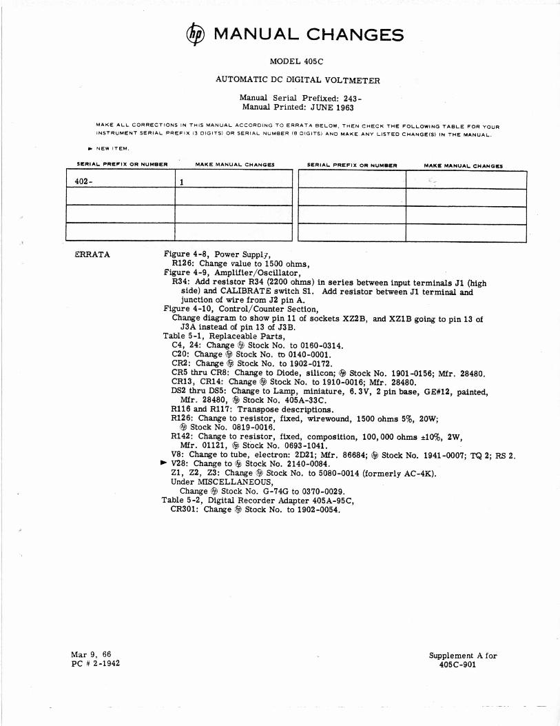
@ MANUAL CHANGES
402 -
,
1
MODEL 405C
AUTOMATIC DC DIGITAL VOLTMETER
Manual Serial Prefixed: 243- Manual Printed: JUNE 1963
Mar 9, 66 PC # 2-1942
Supplement A for 405C-901
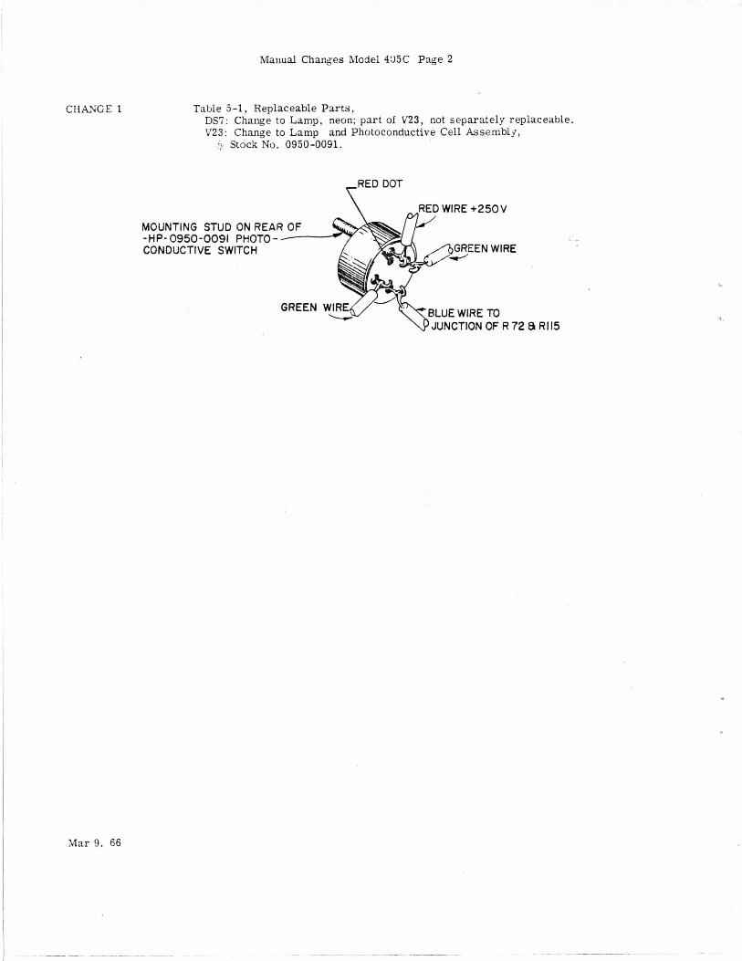
Manual Changes Model 435C Page 2
CHANGE 1
I , I
I
, I
I
i I
Table 5-1, Replaceable Parts, DS7: Change to Lamp, neon; part of V23, not separately replaceable. V23: Change to Lamp and Photoconductive Cell Assembly,
5 Stock NO. 0950-0091.
RED WIRE +250V
MOUNTING STUD ON REA - HP- 0950-0091 PHOTO - CONDUCTIVE SWITCH
ON OF R 72 8 R115
SALES & SERVICE OFFICES
AFRICA, ASIA, AUSTRALIA
Hewien-Pachard soum
Howard Place. Cape Province 7450 Pine Park Centre, Forest Om; Plnolanda. ~ a g PIOVVI I~ . rhos Tel Telex 53-7955 57.0006 thu 9
P . d T i % ANGOLA Telectra Empresa Tlfflica do
Equioamentos EIIRncos. S A.R.L.
R. Barbosa Rodngua. 42-I'OT.' Caixa Postal. 6487 Luanda TeI 35515fi Cable TELEClRA Luanda AUSTRALIA Hewlen-Packard Auslraha
31% J&h Strea Blackburn. ViRona 3130 P 0 Box 36 Doncaster Eut. W c l m 3109 Tel 89.6351 Telex 31-024 Cable HEWPARO Melbourno
BIUB star L I ~ . 1-1-11711 Samiini Om Road SuundHabad 5W W 3 T e l 70126. 70127 Telex: 015459 Cable: BLUEFROST Blue Star Ltd. 2/34 Kodambakkam Hioh Rudd Madras 600 034 Tel 82056 Telex. 041.379 Cable BLUESTAR
INDONESIA BERCA Indonesia P.T. P 0 BOX 496IJkt. Jln Abdul MUIS 62 Jakarla Tel 40369. 49888,49255,356038 Telex Jh.42895 Cable. BERCACON BERM lndonssu P.T. P 0. Box t74iSby. 23 Jln Jimmo
Cable BErcacon ISRAEL Eieclronia Enginwrinp Dv.
of Molomla Israel Lid. 16, Kremenatski Strasl P 0 Box 25018 Tel-Avlv Tei 38973 Telex 33569 Cable 8ASTEL Tel-Am
YokO(awa-Hnrf~-n-Padrd LM. chuo Biag.. 4m H O O ~ 4-20. Nshinaka ima bchoms Yodogaua-tu, dsaka-shi Osaka.532 Tel 06304-6021 Telex 523.3624
?E%
JAPAN
HONG KONG Schmidt 6 CO (Hong Kong) Lld P 0 BOX 297 Connaught Cenba. 35th Floor Connaught Road. Centnl
Telex 74766 SCHMC HX Cable SCHMIOTCO Hang Kong
Ye?I.E%*
YOkOgawbHewien-Padrd Lld lnoue Building 1348-3 &ah)-dm. l-chomo Atsugl. Kanagawa 243 Tel 0462-24.0452
TAIWAN Hewien Packard Far Easl Lid Talwan Branch 39 Chung Hsiao Wosl Road Section 1 7th noor Talpd Tel 3819160-4 3141010 3715121
Ex1 270-279 Cable HEWPACK TAIPEI Hewien-Packard Far East Lid Taiwan Branch 66-2 Chung Chmg 3rd Road
~e?o$~~%lB-Kaohstung Analytical Onb San Kwang Insbumom Co , Lid 20 Yung sut Road Taipei Tel 3715171-4 (5 Iina) Telex 22894 SANKWANG Cable SANKWANG Talpei
NEW ZEAUND Hnrlm-Packard (N.Z.) LM. 4-12 Crulcbhank Stred Kilbirnke. Wellinpton 3 P 0. BOX 9443 Counn9 Wdllngton Place
TeI 877-195 Cable HEWPACK Wolntqton HewietbPackard (N.Z.) Lid Pakuranga Profeelanai Centre 267 Pakuranga Highway Box 51092
Cable. HEWPACK AucLImd AnalyhcallMadicai Only Medical Supplies N.Z. ud. Scientihc 08wsm 79 Carllon Gore Road. NnmarkM P 0. Box 1234 Auckland Tal. 75-289 Cabls DENTAL AuckImd
;e7k;Ev
Vokoaawa-Hewlen-PacM LM. Kumapaya ASahi Hachiluni Building 41h Floor 3-4 Tsukuba Kuma aya Sadima380 Tal 04!624:6563
INDIA Blue Star Lld. Kastun Buildinpr Jamshedli T i t i Rd
Telex 011.2156 Cable: BLUEFROST Blue Slar Ltd Sailas 414:2 Vir SMW MUQ Prabhadwi Bomba 400025 Tel 45 A 87 Telex 011-4r3S3 Cable FROSTBLUE Blue Star Lld Band Box HOYU Prabhaden Bomba 4W025 Tel 45 A 0 1 Telex 01 1-3751 Cable BLUESTAR Blue Star Ltd. 7 Hare Slreet P 0 Box 506 CaIcuIla 7 m W1 Tel 23-0131 Telex 021-7655 Cable BLUESTAR Blue Star Lid !handail House r l h b 8th Floor 91 Nehru Place New Oelhl 110 024 Tel 634770 b 635166 Telex. 031-2463 Cable: BLUESTAR Blue Sur Lid. Blue Star House t1111A Magarm RW Ban .lore 560 025
Telex 043-430 Cable SLUESTAR Blue Slar Lid MeeakSn! Mandiram uU1678 Mahama Gandhl Rd. Coehln 662 016 Tal 32069 32161.32282 Telex. 0886514 Cable BLUESTAR
Y;m2?&;Y 020
l e i jr,,
PAKISTAN MuShko 6 C o m p l y LM. Oosman Chambers Abdullah Hamon Road Karachl-3 Tel 511027. 512927 Telex. 2694 Cable COOPERATOR Karadli MuShko 6 Company. Ud. 388. Satellite Town Rawel lndl Tel 41924 Cable. FEMUS Rnnlpindi PHILIPPINES The Online Advanced
Systems Corporanon Rlco Home Amorsolo fr&4I:;y$ cor. Herrua Makan Slr.
Metro Manila Tev Telex 85-35-~1, 3274 ONLINE 8w-9i.8s.32.2i
KENYA Technical Eoginmng
Servlces(E.A. ILld. P.0 Box 18311 Nairobl Tel 5 5 6 7 9 1 5 5 ~ ~ ~ o / s s n % Telex 22629 Cable. PROTON Medical Only lnternahonal Amdio(E.A.)LM. P O BOX 19012 Nairobi Avpon Nairobi Tei 336055156 Telex 2220112Z301 Cable INTAERIO Naimbi cn-5.
3 Hewlen-Packard Australia ptv Lid
31 Bridge Stred Pymble New South Wllos, 2073 Tel 449.6566 Telex 21561 Cable HEWPARO Sqdnej newlen Packard Auslralia
prv Ltd 153 Greenhill Road Parksido S A 5083 Tel 272 5911 Telex 82536 Cable MEWPARD M d i d e Hewlen-Packard Auslraha
? Ltd 141 !tirlmg Highway Nedlandr W A 6009 Tel 865455 Telex 93859 Cable HEWPARO P a m Hewlen Pickard Ausbaha
Phl Ltd
F y r h w l c k A ! T 2 w 9 Tel 95-2733 Telex 62650 Cable HEWPARO Canlara Hewlen Packard Ausmha
121 Wollongon shsa
m" I td
TANZANIA Medical Only lnlernational mad10 (E.A.), Ud. P 0 Box 861 Dar es Salaam Tel 21251 En. 265 Telex 41030 AnalyflcdllMedicai Onb
Medical Supphos N.Z. LM. Pnvaie Bag Norne and Parumoana sirwn Porlru. Tel 75.098 Telex: 3658 AnalyticaliMadical Onb Medical S u p p l i ~ N.Z. LM. P 0 Box 309 239 Slanmore Road Chnstchurch Tcl. 892419 Cable. OENTAL Chr imurch AnalyticaliMediwI Ow Medical SUPplleS N.Z. ud. 303 Great King Stred P 0 BOX 233 DUMdln Tel 86617 Cable. OENTPiL Ounodln
i%iTg Elecaonio CO. LM. 15th Floor, Oaqonpak B(dg.. 25-5. 1-KA Choong MooRo. Chung-Ku.
THAILAND UNIMESA Co LM Eicom Research Building 2538 Sukumvil Ave Bangchak,Bangkok Tel 3932387 3930338 Cable UNIMESA Bangkok
RHODESIA Field Technicll slier 45 Kebm Road Norm P 0 BOX 3458 Salmbuty Tel 705231 (5 h a ) Telex RH 4122
Seoul Tel (231 m11. 778-3401/213i4 Telex. 22575 Cable ELEKSTAR Smul
UGANDA Medical Only lnternalional Amdio(E A ). LM P 0 Box 2577 Kampala Tel 54388 Cable INTAERIO Kampala ZAMBIA R J Tilbury Zambia) Lld. P 0 Box ,747
MALAYSIA Teknlk M U ~ U Sdn. Bhd. NO 2. Lorong 15/61 Secnon 13 Pelallng Jaya.S.lmgar Tel 54994154916 Telex: MA 37605 Prate1 Engineering P 0. BOX 1917 Lot 259. Salok Road KuChin Sararak Tel 5 3 4 4 Cable. PROTELENG
SINGAPORE Hewlen-Packard Singapwe
1150 Oeoot Rudd Alexandra P.0 Box 58
(Re ) Ltd
:;:%& 2 t ~
Cable HEWPACK. Singapore
soum AFRICA Hewlen-Packard IPtV.). Ltd Soum Africa
Pnvate Ba Wendwood Sandton. Pransvad, a i 4 Hewlen-Packard Ceme Daphne Slreet. Wendyuood. Sandton 2144 Tel 802-104010 Telex. 8-4782 Cable HEWPACK JohUlnesburg
Yorogawa-HMm+ackm LM
Suglnami-ku Tokyo 168 Tel 03-331-6111 Telex 232-2024 YHP-Tokqo Cable YHPMARKEl TOK Z3 724
29-21 %kaldo-HlgaShIJ-chome
si %wY" Teachers Unioll Buikbng 495.493 60undary Sirem Spring Hill. 4000 Ilueanslmd Tel 229-1544 Caale HEWPARO Bnsbmo
Yokogawa-HewieIl.Rckara LM. Nakamo Building 24 Kami Sasaiimbbo Nakamura-ku. Naggoy.. 4% Tel: 052 571-5171 Yokogawa-Hewlen.Packua ud. Tanipawa Builalno 2-24-1 Tsuruya-cno Kanagawa-ku Yokohama. 221 Tal 041312.1252 Telw 382-32734 YHP YOK
.. . _ _ Lusaka Tel 73793 Cable ARJAMEE. LuslLl
The Eleclmnm
N6Bl7iO Oyo Road Oluseun House P M B 5402 Ibadm Tel 61577 Telex 31231 TElL N i g m Cable THElElL lbldan
lnstrumontanon LM. GUAM MedtcaIIPmon&i Calwlamn Oniy Guam MeLwI supob. ~ n c Jay Ease Building. Room 210
Tamunin 96911 Tel 646-4?13 Cable EARMEO Guam
P 0 801 8947
MOZAMBIOUE A N Goncalves. LM. 162, 1' Apt 14 A". 0. Lull Cam Postal 107 Maputo Tel. 27091, 27114 Telex. 6-203 NEGON Ma Cable: NEGON
OTHER ARUSNOTUSTED, CONTACT: Hewlen 3200 Hillview Packard Aw ~ntorwntmmai
Palo Alto California 94304
Cable HEWPACK Palo Alto Telex 034-6300 034-8493
i l l rwx 14151 910-373-1267 8561501
CANADA
ALBERTA ONTARIO Hewlen-Packard Canada) Lld. ii62oA. i68m Atreet Edmonton T5M 379 Tel (403) 452-3670
Hewlm-Packard (Canada) LM. newlen-Packard (Canada) LM. Hewien-Packard (Clnadl) Ud. H M e n - P a d 3 (Clnada) LM. HewIen-Packard (Can&) LM. 275 Hymus Blvd. 210.7220 Fisher SI. S.E. 10691 Shellbndgc Way 380-550 Century SI. 8W Windmill Road €877 Goreway Onvo Calga T2H 2H8 Rlchrnond VEX 2W7 Tel: ( 4 x 1 253-2713
Hewlm-PacM (Canada) Ud. 1020 Morrison Or. Onavm K2H 8K7 Tel. 1613 620-6483 OUEBEC
BRITISH COLUMBIA MANITOBA N W A SCOTIA WX. 616563-1636 Hewlen-Packard (Canada) Ud.
Tel. 1604) 270-2277
WX' 610-831-2431
P d n P Clair. HOR lG7 MIssIMaU a L4V 1M8 Tel 1514\ 697.4232 Tel' (416 6 8 9430 TWX 810-422-3022 ContlR newlen-Packard (Canada)
FOR CANADIAN AREAS NOT LISTED:
Ltd. in Missmauga. TWX: 610-821-6141 TWX 610-9255059 Twx: 610-671-3531 WX. 610-271-4482 HFX TWX 6 l b d k 4 2 4 6 TW 05821521 HPCL
CENTRAL AND SOUTH AMERICA ARGENTINA ;eylen-Packard Argentina
ECUADOR Camputadoras y Equlpos Eleclrdntcos P 0 Box 6423 CCI Eloy Allam NO 1824.3Wa ouno Tel 453 482 Telex 2548 CYEOE EO Cable Sagita-Ouita Mmical Only Hospilalar 5 A Carilia 3590 Robles 625
Tel 545-250 Cable HmprtaIar.Outo
EL SALVADOR Instrumenlacion y Pmcosammto
Eleclmnico de el Salvador Bulevar de 10s Heroes 11 48 San SaivadOl Tel 252787
aunt0
MEXICO Hwlen9ackard M m n . S A de C.V Av. Penlerlw Sur NO. 6501 Tepepan. XoChimilCo MWCO 23, O.F. Tel 905-676-4600 Telex 017-74.507 Hewlen-Packard Merdcana. S A de C V. Ave Constituadn NO 218d Monterrey. N.L. ~
Tei 48-71-32, 48-71-84 Telex 038-610
HewlebPackard do Bras11 , .I- ,I", COLOMWA lnssumentacidn Henrlk A Langabaek h K i a S.A. Carrera 7 NO 48-75 Apamdo Aeso 6287 Bogotd. i 0 E. Tel 59-88-77 Telex 046400 Cable M R l S Bogol lnslrumentacion H A Langebaek h Kier S.A. Apanado Aereo 54098 Medollm Tel 304475
VENEZUELA Hewlen-PacWd de Venezueli C A P 0 Box 50933 Caracas 105 Lor R u i n s None 3a Transversal Edilicio Segre Caracas 107 101 35-00-11 (ZOlina) Telex. 25146 HEWPACK Cable: HEWPACK Caracas
PERU CampaOla Eledro M6dica S.A Los Flamencos 145 San Isldro Canlia 1030 Lima 1 Tel 41-4325 Telex: Cable: Pub. ELMEO Boom Lma 25424 SISIORO
Hewlen-Packad do Bras11 I e C Llda Rua Siaueira Campm. 53 COoImbana 20000-Ria de JmdroRJ Tei 257 80-94.000 (021) Telex 391-212-1905 HEWP-BR Cable HEWPACK
BOLIVIA Casa Kawn S.A. Calle Potosi 1130 P 0 BOX 500 La Pa2 Tel. 41530.53221 Teiex CWC BX 5298.1Tr 35MM82 Cable KAVLIN Ria de Janeim
NICARAGUA Roberto Terdn G Aoanrdo Postal 689 Edificio Terdn Managua Tel 25114 23412.23454 22400 Cable ROTERAN Manaaua URUGUAY
P a o i i i m n O o S.A Concrr ai e mdumai Are" oa iaiu 2877 Carl la oe ;orrca 370
COSTA RICA Cienshca Coslarnnns SA, Aveniaa 2. CaIIo 5 San Pedro de Monfsr do OU Apartado 10159 San JOH Tcl 24-38-20. 244819 Telex 2367 GALGUR CR Cable GALGUR
PANAMA Elmrdnico Balboa. S.A. P 0. BOX 4929 Calle Samuel Lewis Cu1d.d de P m m m Tel 64-2700 Telex. 3485128 C U N ~ ~ U .
Can# Zone Cabia: ELECI90N F'anm
FOR AREAS NOT LISTED. Hewlen-Packard 3200 Inter-Amencas Hillview Ave.
Palo Alto. Californli 94304 Tel I4151 856-1501 WX 910-373.1260 Cable HEWPACK Pato Alto Telex: 034-63W. 034-8493
CONTACT:
m
BRAZIL Hewlen-Packmd do Bras11 I e C Ltda Alameda Rm Negm. 750
06404 B a r n SP Tel 524-3222 Cable HEWPACK Sa0 R u l o
AIphaVIIIe
CHILE Calcsgni y M m n e udr. Alameoa 580-M 807 Casilla 2118 5.nti.go. 1 Tei 398613 Telex: 3520001 WLMET Cable: CALMET Saima~o
GUATEMAU IPESA Anenida Relonna 3-48. Zona 9 Tel Gualmmh 318627.314nj86.58471-5.(x1.9 C
Tela 4192 T M r o Gu
Montev1d.o
Telex 702 PUBLIC BOOTH PARA Tel 40-3102
6C-l l47 PABLO RRRANOO TELEFONO
Cablo: d A i i U i i M o n m d w

EUROPE, NORTH AFRICA AND MIDDLE EAST Hewten-Packad Espanda s A Av Ramdn y Catat 1 Edilicio Sevilla planta 9 ' Seulll. 5 Tel 61 44 5468 Hewlen-Pacbrd Es anola s A EOIIICIO Albia 11 7' i E-Bilbao 1 Tel 2? 83 06123 nz M
UNITE0 ARAB EMIRATES Emitac Lid P 0 Box 1641 Sharlah Tel 24121-3 Telex 6136 EMITAC SH CaOle EMITAC SHARJAH
NORWAY Hewlen Packard AIS Osterdalen 18 PO BOX34 N-1345 Osteraas Tel lo21 1711 80 Telex 16621 hpnas n POLAND Biuro lnlormaci Technjunq Hewlen Packard Ul Slawkl 2 6P 00 9M Wmszawa Tel 33 25 86 39 67 43 Telex 81 24 53 hepa pl UNIPAN B.ui0 Obslugi Technianel 01 447 Warszawa UI NeweIska 6 Poland Zaklady Naprawae Spmtu
Medyanego Flat: Komuny Parqsbq 6 90-007 L d d i l e i 3 4 - 4 1 337 83 Telex 686981
AUSTRIA Hewlell-Packard Ga.m.b.H Handelskal 52 P 0 BOX 7 A-1205 Vlenna Tel 351620-29 Cable HEWPAK Vienna Telex 75923 hewpak a
BELGIUM Hewlen.Pacrard Benelux S A . N V Avenue du Cot-Ven. 1. (Groenkraaqlaanl 0.1 770 BrusseIe Tel. 1021 660 0047.6n-2240 Cable PALOEEN Ervsxls Telex 23.494 paloben bru
FRANCE Hewlsn-Packard Franc8 Ouanier de CounaBo(uf B O m Poslale NO 6 F-91401 Orsay Cedex Tel (11 907 78 25 Cable HEWPACK Onay Telex 600048 Hewlen-Packacd France Bureau de vente de Lion
Chemin des MOUIIICS B P 162 F-69130 Esully Ceder Tel 178) 33 81 25 Cabla HEWPACK Eculy Telex 31 06 17
Le saqm
ITALY Hewlell-Packad ltaltana S.p.A. via Amengo VKDUCCI 2 Casalla postale 3645 1-20124 MIIana Tel 102) 6251 (10 lines) Cable HEWPACKIT Milano Telex. 32058 Hewlen-Packard llaliana 5.p.A VIP PelllaO 9 1-35100 P a d o w Td 10491 66 46 66 Telex 41612 Hewpa* Hewlen-Packard l t a l i m S.B.A. Via G Armellm l o 1-00143 ROma l e 1 (061 54 69 61 Telex. 61514 Cable HEWPACKIT Rami
UNITED KINGDOM Hewlen-Packard King Slreel Lane ttd
GE-Wlnnarsh. Wokmgham Berkr RGl l 5AR Tel 107341 78 47 74 Cable Hew le London
Hewlen-Packard Lid. Trrlalqar House Navigation Road Ai l rmcham Cheshire WA14 INU Tel 1061) 928 6422 Telex 66s068 HewIen.Packard Lld Lygon Coun Herewarn R m Oudley Road Hale?rOl*e". West Miolands 862 8SO Tet Telex 10211 339105 550 9911
Hewlen-PPCkard Lld Wedqe House 799. London Road GB-Thornton Heam Surre CR4 6YL Tel ( i l l 684 o I o ~ i 8 Telex 946025 HeWIell-Pachard Ltd 10 Wesley SI Cas l l do rd Yolks WFlO tAE Tel (09771 550016 Telex 557355
Telex 847176'9
HevlelI.Packard GmbH Technisches Burn HamBurq Wendenstwse 23 0-2000 Hsmbur 1 Tet 10401 24 13 L Cable HEWPACKSA Hamburg Telex 21 63 032 hphh d HWleK.%kard GmbH Technlscher Burn Hannwer Am Grosrmarkl 6 0-3003 Hamover 91 Tel (05111 46 60 01 Telex 092 3259
~ .. .. .- Hewlen-Packard Espanola S.A. CiRamon Goidillo 1
E-Valsnci.-lO Tel 36-361 13.541561.13.58 SWEDEN Hewlen-Packard Sveoge A8 Eniqnetsvaqen 3, Fack S-161 Bromms 20 Tel 1061 730 05 50 Telex 10721 Cable MEASUREMENTS
Stocknolm Hewlcn-Packard Svmqe A0 Frdtaltsqaian 30 S-421 32 Vdstra FrdIunds l e 1 1031) 49 09 50 Telex 10721 vta Brommi omce
(Entlo j
Hewten-Packam GmbH Technischa Burn NlrnberQ Neumeyershme 90 0-8500Ndmbeq l e 1 (09111 56 30 83 Telex 0623 860 Hewlan.Packard GmbH Technlscher 6Bm MBnchsn Ercnanmasse 5 0-6021 T a u r k l r c k n le1 1089) 6117.1 HewM-Packarc Gmbn Tecnnlscnes 6Bm Bedin Kailhslrasse 2-4 0-1wo B.,ll" 30 Tel. 10301 24 90 8d Telex 018 3405 hpbln d
SWITZERLAND Heulen-Packarn (Schweiz) AG ZUICheistrasse 20 P 0 Box 307 CH Tet 6952 (01) 7305240 S C h l l w ~ Z u r l b
Telex 53933 h g ch Cable HPAG CR"
Hewlen-Pachrd France Le Ligoures Bureau de venta de Maocilles Place Route de WIlenuwe F-131 W AIX-~II-PIOV~IIC. Tal (421 59 41 02 Cable HEWPACK MARGN Telex 410770
CZECHOSLOVAKIA V w o ~ o ~ s a Provozni Zakladna VydumnyCh Uslaw Y Bechoactm CSSR-25097 BMhOVICe Y Prahy Td 699341 Telex 121333 Instme of ~ c d r u l 01onm Vyskumny Ushv Lekarsket Bioniky Jedlova 6 CS-86346 Bralislav,Knmmn Tei 4251 Telex 93229
MeoicaI only Mcndlnter lnlerarnblo Mundid de Comdrdo S l . 1
GREECE Kasias ~araymnt i 6 Omirou strm A t h e l a 133 Tel 32 30 303152137 731 Telex 21 59 82 RKAR GR Cable RAWR ATHENS Anal cat Only INT80 G Pacamanassou k CO 17 Msmi Streel Athens 103 l e t 5522 91Jiszzl s)9 Telex 21 5329 INTE GR Cable INTEKNIKA Medic4 Only Technamed Hellar ud 52 Skoufa Slreel Athens 135 Tcl 3626 972 Telex 21 4693 Cable ETAIAK
SYRIA General Electronic Inc Null Basna Anna1 Ebn Kays Strwl P 0 Box 5781 Damascus Tel 33 24 67 T ~ I ~ X 11215 i n t a L Cable ELECTROBOR DAMASCUS Sawah MedtcallPeroonal b Co Calculatm only
Place k m d B P 2308 Damascus Tel 16 37 -19 697-14 268 Telex 11306 SATACO SY Cable SAWAH DAMASCUS Sulaman Hllal El Mlan PO Box2528 Mamoun Eilar Slreel 55-58 Oemscv rTe l 11 46 63 Telex 11270 Cable HltAL DAMASCUS TUNISIA Tunisie Elenrnnique 31 Avenue de la Libem Tunls Tel 260 144 Corema 1 ler AV dm Cdrmage Tunls Tel 253821 Telex 12319 CABAM TN N R K E Y TEKNIM Company L a Rira Sah PehIev~ Caadesi NO 7 Kavailidere A m Tel 2756W Telex 42155 TKNM lR Medial only E M A MUheldlSllk KOllWlt Sirkcti Meoiha Edem SoWk 4116 Yuksd Caadesl Ankara l e i I 7 56 22 Cable EMATRAOVAnkara
6 6 Box 2761 Aventda Anlonu lupuslo
de Apuiar 138 P. Lisbon Td I191 53 21 3117 Telex 16691 munter p CaBlc INTERCAMBIO Usbon
Hewlen-Packard Ltd 1. Wallace Way GB-Hltchln Hemorcshire, 564 OSE Tel (0462) 31111 Telex 82 59 81
Tel 19% 51 42 44 Cable HEWPACK 74912 Telex 740917 DDR
EnWcldungslaMr der TU Oraden FOnChuqsinStbl MamBq OOR.7305 Waldh.imlWnsbarg rei 37 667 Telex 516741 Erporl Contau AG Zusnch Guenmer Fargber Schleqelslrarse 15 1040 Berlin Tel 42-74-12 Telex 111089
RUMANIA Hewlen Packard Rsprslamm Bd n Llcesm I8 B"c"ra.11 Tel 15 80 23113 80 85 Telex 10440 I l R U C lnlrcprinderea Penla
lntrehnarea SI Reuararea UBlqdor de Calcul 6-dul Prof Oimitrie Pompei 6 Bucurestl-Senorul 2 Tel 66 20-70 88 24-40 88-67.95 Telex 116 SAUDI ARABIA Manern Electrmc Ertaolishment (Head Omm) P 0 Box 1228 Lghdadjah Slmel Jeddah Tel 27 7% Telex 40035 Cabls ELECTA JEODAH Modem EImmnic Establishment (Iranch) P 0 Box 2728 RI adh Ter 8258166232 Cable R4OUFCO
Hewlet-Packard Lld 2C Long Avonbep Mile Road lndusnial €sale Dubl in 12 Tel Dublin 5143221514224 Telex 30439 USSR Hewten-PacCM Reoresentalive Omce USSR POBOYSkY Bo~levard 4117-hr 12 Moscow 101000 Tel 207 59 24 Telex 7825 newpak su YUGOSLAVIA lskii SlindaidlHeWmn-PaCrd Mirloriceva 61000 L lub l lma 38Nll
Tel 31 58 79132 16 74 Telex 31583 SOCIALIST COUNTRIES NOT SHOWN PLEASE CONTACT Pewlett Pxkard Ges m b H Hindelskif P 0 801 7 52
A-1205 v ieme. Ausma TeI (02221 35 16 21 to 27 Cable HEWPAK Vienna MEDITERRANEAN AND MIDOLE EAST COUNTRIES NOT SHOWN PLEASE CONTACT: Hewlen Packad SA Medilerranean and Mddle Earl Operalions 35 KOIOLOtIOmI Street Raua Kelsllanou GR K~lkssfa Athens Greece Tel 6080337 359t429 Cable HEWPACKSA Amms FOR OTHER AREAS NOT LISTED CONTACT HeWlln-Packaid S A 7 we nu Bois d u Lan P 0 Box CH-1217 Meynn 2 Gem- Swlueriand rei 10221 62 70 00 Cable HEWPACKSA Geneva
KUWAIT AI-Khatdiya Tradlnq k
Kuwalt P.oco;:;?:t%m
Te1.42 4910111 1721
Hewlen-Packard Fnnca Bureau de vente de title lmmeuble Pencentre Rue van Gag" F 59650 V l I I e m u ~ . d A s q Tel 120) 91 41 25 Telex 16 01 24f DENMARK
Hewlen-DICkard a oatave1 52 OK4460 Blrkwad Tel 1021 81 66 40 Cable HEWPACK AS Telex 37409 hpas dk Hewien-PPCkm PJS Navewe1 1 OK-06w Sl lkeborg Tel 1061 62 71 66 Telex 37409 n as dk Cable HEWPA& AS
LUXEMBURG Hewlet-Pachard 0eneIu S A i N V Avenue du CoI.Verl 1
Hewlell-Pachrd Frani Bureau de Vente Cenlre d atlaires Pms-Nnd BPtimenl Ampere Rue de la Commune de Pam 8 P 3W F-93153 Le Blanc Y.nll C d d m TH 1011 931 88 50
HUNGARY MTA M~sz(1Ngy 6s M k d h d l n i h l
Szolgilata Hewlen-PacWrd Smim Lentn Kn 67, P 0 . 8 0 ~ 241 1391 Budapest VI Tel 42 03 38 Telex 22 51 14 ICELAND
Q'zk;;:3,
Tal 1021 672 22 40 Cable P4LOBEY Brusxls Taex 23 494
MOROCCO Oolbeau 81 v e I(m1chI C.sablanc. Tel 22 41 82187 Telex 2305122833 Cable. MATERIO
6!3vd . Brahim Roudani C a s a b l m u Tel 25 16 76R5 90 99 Telu. 23 739 Cable. GEREP-USA Cogedir 2 Rued ' Aqadlr. B.P. 1% Casablmes Tel. 27 65 40 Telex 21 737 Cable COGEDIR
Hwlett-Packard France Bureau de vente ne Bordaau
EGYPT I EA International Eqinswirq kodala 24 Hussan Hegui Sum Kasr-el-Aini C a m Td 23 829 T e l n 2067 CaBle INTENGASSO
Medial Only Elding imam Cmnprny lnc Halnamvol! -\~gpVagbhl P 0 BOX 895 IS47eykIavIk Tel 1 58 2011 63 03 Cable ELOING RQkmk IRAN Hewten-Pac!ard INI LM NO 13. Founimh SI Mir Ernad Avenue P 0 BOX 4112419 T e h r m ret 0510112.5 Telex 213405 h a p ir
QERMAN FEDERAL R E W B U C Hewien-Packard GmBH VerliiebUenliale FranWun Berner Slrarre 117 POInlCh 560 140 0-€400 FmnkfuR 56 Td 10611) 5044.1 Cable HEWPACKSA hnlclurl Telex 04 13249 hpfhll d HewIen Packam Gmbn Tecnnlscnes Bur0 BOblm n Harreobargcr Slrasse 118" 0 7030 B d b l l n g m Wbmanberq rei 107031 667-1 Cable HEWPACK Bbbhngen Telex 07265739 bbn Hewlm-Pachard GmbH TecnnmheE 6um o ~ l s w o r ~ Emanuel-Lemr-Str t 1Seamrn) 0 4000 DUsseIdM1 Tei 102111 53711 Telex 085 86 533 hpdd d
Modem Elenronic Erlabhshmenl (Branch) PO Box 193 AI-Kh0b.r l e 1 44678-44813 Telex 67041 OTESTA Cable ELECTA At-KHOBAR
Mohamed Sun1 Amin Sam, Amin Tradinq OMca 18 Abdel Ani Garfsh Abd,nd.l* Tel 24932 Cable SAMITRO CAM0
SPAIN Hewlen-Packard Etpraola. S.A. Calle J e w 3 E-Madrld 3 Tel (11 458 26 W (10 lines) Telex 23515 hpe Hewlen-Psdarc EspaPOIa. S.A. Milinesado 21-23 ~-Bamelona 17 ,e l 13) 203 6200 (5 tlna) Telex 52603 hpbe e
f lNLAND Hcwlen.Packard OY NahhhoUiUnn 5 P 0 Box 6 SF-00211 Helsbkl 21 le i 1901 6923031 Cable HEWP4CKOY Helsinb Telex 12 1563 HEWPA SF
IRELAND Herten-Packard Ltd King Streer Lane GB Wmnarsh. Wokmghm Berks RGl l 5AR Tel 10734) 78 47 74 Telex 647178 Cable Hewpcc London
NETHERLANDS Hewtell-Packard Benelux ti v Van Hewen Goedhamaan 121 P 0 Box 667 NL-Amstelveen 1134 l e ! m o i 47 20 21 Cable PALOBEN Amsmam Telex 13 216 hepa nl
Analytical Yilmaz Oqurek only
Mil11 Muddaa Cad 1616
Ankara Tel 25 03 0 9 . 17 80 26 Telex 42576 OZEK TR Cable OZYUREK ANKARA
K.IIay
UNITED STATES MICHIGAN 23855 Research Orwe Farmlnglon Hills 48024 T i l 13131 476.64W
OREGON 17890 SW Lolrer bones
Fwry Road Tualalm 97062 TEl (5031 620-3350
? 0 Box 42816 10535 Hawin Or Ho~slon 77036 rei (7131 776-64ca 'Lubbock Medial Sawice on ret I6061 799.447l
ALABAMA P 0 Box 4207 8290 Whitesburg Or HUntsvIIIe 35802 l e i (2051 681-4591 8933 E Roebuck 81vd Blrmi ham 35206 TeI (221 035-220312
9M)6 Aem Om San Diego 92123 Tel I7141 279.3200 *TWZ.". Tel (213) 705-3344
P 0 BOX 23333 724 West Centre Awe. Kalamazm 49002 Tel 16061 323-8362 MINNESOTA
HAWAII 2875 So Kmg S m # Hon~lulu 96826 Tel 1808) 955-4455 ILLINOIS 5201 Tollvln Dr Ralllng b d a Wow T d (3121 255-98W TWX 910-687-2260 INDIANA 7301 North Shadeland Ave lndlana 011M6250 Tet 1317p842-1000 T W X 810-280-1797
205 Billy MilChell Road San Antonto 78226 TcI 1512) 434-8241 UTAH 2160 sovm 3270 west s t m Sal1 Lake Cay 84119 Tel (8011 972-4711
2400 N Prior Am. SI. Paul 55113 Tel 1612) 635-07W
COLORADO 5600 OTC Parkway Englewmd 80110 Td 1303) 771-3455 CONNECTICUT 12 Luoar orlve New Haven 06525 T d (203) 389.6551 TWX 710-465.2029 FLORIDA P 0 Box 24210 2727 N W 62nd Slm FI. LaYderd.1. 333139 Tel (3051 973-2600
ARIZONA 2336 E Wa nolia St. P h m I x 6!034 Tel I6021 244-1381 2424 East Aiaqon Rd TUWDn 85706 Tei. 16021 869-4581
MISSISSIPPI 322 N Marl Pian Jackson 392W Tel 1601) 962-9363
VIRGINA P O 12778 NO 7 rtoger Exec. Center suite 212 Norfolk 23502 Tel !604) 461-4025m P 0. Box 9669 2914 Hungary Springs Road Richmond 23228 Tel 18041 285-3431
aeiiefieia t203-114th onlce Ave pk S E
Bellevue 98004
WASHINGTON
Te' 12061 454-3971 W X 9'0-443.2446
'ARKANSAS Medical Sewice Only PO 30x5646 Brady Station LWe Rock 72215 l e i iMli 316-1844 CALIFORNIA 1430 Easi Orangethorp AM Fullerlon 92631 Tel 17141 670-low 3939 Lankershlm 8oulNard
2;;l;;:y%$ 91604 T W X 910-499-2671 5400 West Rowrans Blvd. P 0 Box 92105 World Way Posial Center Lo. Angel- 9OW9 l e 1 (2131 970-7500 TWX 910-325-6608 *LOs A n g e l n Te: 12131 776-7500 3003 scan ~ouievard Sann Clara 95050 Tel. 14061 249.7000 w x 910-338-0518
? l 7 ~ % 6 1 6 5 646 W N o m Markel LW S.C"mM10 95634 Tel (9161 929.7222
IOWA 2415 Hem Road l o l a City 52240 Tel (3191 338-9466
NORTH CAROUNA 5605 Roanne Way Greensboro 27405 Tel 19191 652-1000
SOUTH CAROLINA P 0 E m 6442 6941-0 N Tienholm Road Columbia 29260 Tel (8031 782-6493
4428 Emerson Slnel Unit 103 Jacim~nvill. 32207 Tel 19041 725-6333 P 0 Box 13910 6177 Lake Ellenor Or orlmao 3z6w Tel (3051 859-2900 P O BOX 12826 Suile 5 6ldg t Onice Park Norm PeOsaCoI. 32575 Tel 19041 478-0422
KEN TU C K Y M e a m 39001 Atkinson Or Suile 407 Alkmon Seam Loulswlls 40218 Tel i5021 456-1573
NEBRASKA
K E $ L a a suite I10 Omaha 68106 Tel (402) 392-OH8 NEVADA !as Vega.
rei ,7021 736-6610
onio 0iag 330 MedicallCOmpul8r Only
1313 E Kemper Rd c,nc,nn.n 45426 TPI i j l 3 1 671-7430
TENNESSEE 8914 Kings:on Pike Knoxville 37922 Tel (6151 523-0522
LOUISIANA P 0 Box 1449 3229-39 Williams EouIwam Kennar 70063 Tel (504) 443-6201
'WEST VIRGINIA Medml1Anslybcil Only Charleston Tel 13041 345-1640
3027 Vanquard Or Oirector s Plaza Mom hlS38131 Tel i & ~ j 346-0370
NEW JERSEY w '20 c c n r ~ l r Ra Paramus 07652 TP ??I 265 MOO TXX "3-990-4951
M A R Y U N D 6707 whitestone Road Balllmas 21207 Tet 13011 944 .54~ TWX 710-862-9157 2 Choke chew h a d Roekrllle 20850 Tel 13011 946-6370 TWX 710-828-9684 MASSACHUSETTS 32 Hamell ave LWln On 02173
T M 7 0-326-6904 -d ,69171 a61-89eo
WISCONSIN 9004 Wesr Lincoln AM West Allts 53227 le1 i4141 541.0550
*NashwIle Medial Servtu, only let 16151 244-5448
Cwslal 8rook Prolsulond Building. Roule 35
Emlon rwn 07724 Tel i iOl) 542-1364 TEXAS
4171 Norm Mar sulfa C l l O Et Paso 79902 Tel 19151 533-3555 0 0 Box 1270 201 E Arapaho Rd Richardson 75080 Tel ,214) 231-6101
FOR US. AREAS NOT LISTED: Contact ma reqiunal office nearert you' Aflanta, Georgia. Nonn Rocxville. HoIIpoOd. Maryland Calttornia Rolling Meadows.
i i t m s mar comwete addresses are 1Wed above
Mcdcal Sewica Only Augu.ta 3wO3
Tel ,4041 736-0592 NEW MEXICO P 0 BOX 11634 Station E 11300 Lamar Blvd N E Albuqu=qw 87123 l e 1 15051 292.1330 TWY 910-96%1185
P 0 Box 2103 1172 N Davis Onve W a r n Roblns 310911 Tel 19121 922-0449 'S-Im Only 0138