MODEL 11180A DATA STORAGE - The Hewlett Packard ...
58
MODEL 11180A DATA STORAGE
-
Upload
khangminh22 -
Category
Documents
-
view
0 -
download
0
Transcript of MODEL 11180A DATA STORAGE - The Hewlett Packard ...

MODEL 11180A DATA STORAGE

"J OPERATING AND SERVICE MANUAL
-hp- Part No. 11180-90000
MODEL 11180A DATA STORAGE
Copyright Hewlett-Packard Company 1971 P.O. Box 301, Loveland, Colorado, 80537 U.S.A.
Printed: SEPTEMBER 1971

HP Archive
This vintage Hewlett Packard document was preserved and distributed by
www.hparchive.com
Please visit us on the web !
Prepared by on-line curator: Tony Gerbic
For FREE Distribution Only ***

• • ...:.....,,· ... _ .. , ••• • •.• ~' '•••· • • : ••• ·•.:.,: . !~· ·•~· • -···· ···•'""-- '"' •• :.h.'~O·: ..... ~~·. ·.:...1.:....:.r!"-'-- .,. ,;.~ .>~ ~ .··~· •• ,~~.,...,..-;..~ ..:..:....~ .a. .:.-i..-""-"'~·- ~-~
---------HEWLETT.PACKARD---------
~ CE RTI Fl CATI 0 N
The Hewlett-Packard Company certifies that this instrument was thoroughly tested and inspected and found to meet its published specifications when it was shipped from the factory. The HewlettPackard Company further certifies that its calibration measurements are traceable to the U.S. National Bureau of Standards to the extent allowed by the Bureau's calibration fatility.
WARRANTY AND ASSISTANCE
All Hewlett-Packard products are warranted against defects in materials and workmanship. This warranty applies for one year from the date of delivery, or, in the case of certain major components listed in the operating manual, for the specified period. We will repair or replace products which prove to be defective during the warranty period provided they are returned to HewlettPackard. No other warranty is expressed or implied. We are not liable for consequential damages.
Service contracts or customer assistance agreements are available for Hewlett-Packard products that require maintenance and repair on-site.
For any assistance, contact your nearest Hewlett-Packard Sales and Service Office. Addresses are provided at the back of this manual.
;] ~
r1 !] .
;J
1 J
LJ.
IJ ;j
:J. u·

··] .. .
]
]
.J
J
J
' t .,
Model 1 l 180A Table of Contents
TABLE OF CONTENTS
~fun &~ Section IV (Cont'd) Page I. GENERAL INFORMATION . ........ . .. ... . 1-1 4-22. Turn-On .. . .. .. . ... .. .... .. ..... ... 4-1
1-1 . Introduction ...... .. .. . . . . .. . . . . .... 1-1 4-24. Printer and Dump Hold Cycling . . .... .. . 4-2 1-7. Accessories Furnished 4-26. Panel Transfer . . . . . . . . . . . . . . . . . . . . . . . 4-2
(with Data Storage Only) . . .. .. .. . ... 1-1 4-30. Basic Counter .. .. .... . . . .. .. ... . . ... 4-2 1-8. Accessories Available
(with Data Storage Only) . . .. . ... . . .. 1-1 4-3 7. Preset Triggers .... . . . ........ . ... . . . . 4-2 4-39. Jump . . .... . .... .. .... . . ... . .... .. . 4-3
~fun &~ II. INSTALLATION ... . . .. .. . .. . ... . . . . . .... 2-1
441. Limits .. .... ... .. . ... .... ..... .... . 4-3 443. Measurement Hold .. . ... ... .. . .. . .. . . 4-3
2-1. Introduction .. . ...... .. . .. . . ... . .... 2-1 446. Scanner Control ... .. . .. . . .. .... .. ... 4-3 2-3 . Initial Inspection .. . . . ... . ..... ... .. .. 2-1 4-51. Computer Control . .. ... .... . . . .. . .. . . 44 2-5. Installation of 1l180A into 3480A/B . . . . . 2-1 2-7. Storage Connector . . . .. .. . .. . . . .. . ... 2-1 ~fun &~ 2-9. Repackaging for Shipment . . .. . ...... . . 2-1 V. MAINTENANCE . . . . . .. ....... . . .. ....... 5-1
5-1 . Introduction .. . .. . . ... . . . .. .... . .... 5-1 ~fun ~ 5-3. Equipment Required . ... . . . .. . . .... .. . 5-1 III. OPERATING INSTRUCTIONS .. . . . .. . ... . .. 3-1 5-5. Performance Checks ..... .... . . ... .... 5-1
3-1 . Introduction . . ... .. . .. . . . . .. ..... ... 3-1 5-7. IBCD Check .. .. .. . .. . ... ... .. .. ... 5-1 3-3. Basic Operation . . . ... ... ... .. .. . ..... 3-2 5-8. Storage Check . . .. .. .... . . . . . .. . .. . . 5-1 3-13 . Operation with Single Channel Plug-Ins . .. 3-5 5-14 . Troubleshooting ........ .. . .. . .. .. .. . 5-1 3-18. Operation with Scanning Unit . ... .. . ... . 3-6 3-25. Sample-and-Hold Improves Digitizing . ... . 3-8 ~fun &~ 3-29. Data Storage Used in the 2070A ... ..... . 3-9 VI. REPLACEABLE PARTS ... ... . . ... .. .. .. .. 6-1 3-32. How to Clear Data Storage . .. . .. ...... 3-10 6-1 . Introduction .. .. .. ... . ..... . ... ... . . 6-1 3-36. Applications . .. .. ... .... . .. . . . . .. .. 3-10 64. Ordering Information . .. . . .. .. . .... . . . 6-1
6-6. Non-Listed Parts . ... . ..... .. .. . ... . .. 6-1 Section Page IV. THEORY OF OPERATION . . .... .. . ...... . . 4-1 Section Page
4-1. Data Output ....... .. . .. .. .. . .. . .... 4-1 VII. CIRCUIT DIAGRAMS . .... .. . . ..... .. . . .. . 7-l 4-2. Present Mode (Isolated BCD) . ... . .. .. . 4-1 7-1. Introduction . ..... . ... ... . . .. . ...... 7-1 44. Storage Mode (Memory) . . ... . . . .... .. 4-1 7-3 . Notes .. .... . .. ........ . . .. . . . . . . .. 7-1 4-6. Panel Transfer ........ ... .. . . .. ..... 4-1 4-8. IBCD ... . ... ... .... . ... .. . ...... . .. 4-1 4-13. Inhibit and Printer Hold .. .. . .. . .. . ... . 4-1 Appendix 4-15. Encode (External Trigger) .. . .. . ... . ... . 4- l A. CODE LIST OF MANUFACTURERS 4-1 7. Basic Storage .. ... . . .... . ..... . . . . . . . 4-1 B. SALES AND SERVICE OFFICES
LIST OF TABLES
~~m &~ l -1. Specifications .. . . .. .. . . .. . . .. .. . . . .. . . 1-2/1-3 3-1. Storage Connector .. . . .. .... .. .......... .. 3-1 3-2. Storage Controls ... ... ... .. . . .. . .... . ... .. 3-2 3-3 . Methods of Outputting Data ... .. . ..... . .. . . 3-5 34. Minimum Triggering Rates .... . . . .... . ...... 3-6 3-5. Decoding Output Information for Single
Channel Plug-Ins (3481A3482A, or 3484A) ... 3-6 3-6. Decoding Output Information for the
3485A Scanning Unit .. ... .. . . .... . . ... . .. 3-7 3-7. 3485A/Data Storage Operation for Bursts
of Readings . . . . . . ... . .... . ....... ... . .. 3-8
Number Page 3-8. Improvement in A/D Conversion Accuracy
Using Sample-and-Hold (3482A or 3484A 10 V Range Only) . . .. . .. . ..... . .. . . .. . . . 3-9
3-9 Sample-and-Hold Accuracy (Digitization Rate is Limited to 1 kHz) ... . . .... . . .. .. ... 3-9
3-10. 2070A Rear Panel Connector for Data Storage .. . ... . . . . .. ... . . . . . . . . . .. . 3- l 0
5-1. Troubleshooting .. .. . .. . . . . . . .... .. . . . . 5-1/5-3
6-1. Replaceable Parts ..... . .... ... ......... 6-2/6-6
iii

Table of Contents Model l l l 80A
LIST OF ILLUSTRATIONS
Number Page 1-1. Data Storage . . . . . . . . . . . . . . . . . . . . . . . . . . . . . . 1 -1 3-1. Storage Operations ... . .............. .. . ... 3-3 3-2. Basic Operation of Data Storage ... . .... .. ... . 3-4 3-3. A Jump Command ... . .. . .... . . . .... . .. . .. 3-4 3-4. Printer Output . . .. . . . ... ... . . ............ 3-4 3-5. Preset Trigger ...... . . .. ..... . . . ..... . .... 3-4 3-6. Measurement Hold .......... . ..... . .. . .... 3-5 3-7. Computer Control Enable ..... . ......... . .. 3-5 3-8. Data Storage Timing ..... . ........... . . .. .. 3-5 3-9. Printer Format for 2070A Data Logger . .. . . . .. 3-6 3-10. The Printer Format ... .. . .. .... . ... ... .... 3-7 3-11. Data Storage Used with the 3485A
Scanning Unit ....... . .............. . . ... 3-7 3-12. Jump Printout . .. .... . ............ .... ... 3-7 3-13. Burst Operation . . . ... .. ...... . .... . . . . ... 3-8 3-14. Burst Printout . . ...... . ....... . .. . .. ..... 3-8 3-15. Sample-and-Hold Circuit Position .... . ........ 3-9 3-16. Sample-and-Hold Technique ......... .. . . . .. . 3-9 3-17. Rear Panel of the 2070A Data Logger ........ 3-10 3-18. Trigger Source for Single Channel
Plug-Ins ..... . ... ... ....... . .... . .. . .. 3-10
iv
Number Page 3-19. Clearing Data Storage .... .. ...... . . .... ... 3-10 3-20. Response Time Measurement ......... . ..... 3-11 3-21. Preset Trigger Measurement .. .... .......... 3-11 3-22. Peak Reading ... .. .. . ............ ... .. . . 3-12 3-23. Single Input System . .. ................... 3-12 3-24. Multiple Input System . . .... . ............ . 3-12 3-25. Random Sample .. . .. . .. . ....... . .... . ... 3-12
Schematics and Diagrams 7-1. Isolated BCD .......... . .. .. . . . . ...... 7-3/7-4 7-2. Basic Storage .. . ....... . ....... . . . .... 7-3/7-4 7-3 . Address Counter, Limits ... . ............. 7-3/7-4 7-4. Preset Trigger, Printer Hold, Computer
Control Enable .... . ..... . ... .. ....... 7-3/7-4 7-5. Scanner Control, Jump ... .. .... . ... . .... 7-5/7-6 7-6. Panel Transfer, Printer and Dump Hold
Cycling .... .. .... . .... . ....... .. .... 7-5/7-6 I
7-7. Inhibit, Turn-On, Continuous Cycle . .. . ... . 7-5/7-6 7-8. Measurement Add, Encode . ... ... ..... .. . 7-5/7-6 7-9. Control and Timing .. ... .. . . . . ..... . ... 7-7/7-8 7-10. Data Output . ...... . ... . ... . ......... . ... 7-9
;l
' I.
:1 . '
]
,. '
L l ,'·J !;'
..

r.l, "
t
'r.'.1 •. . :.·,;. ~. . ..
' l - ·~· ,··i
·1
''J . ..
.. ·
··1
J
J
~J . .. ..
•• .!.'...~ -·~ .:-·. _, ;.. '·'.
Model l l 180A Section I
SECTION
GENERAL INFORMATION
1-1. INTRODUCTION.
1-2. The Hewlett-Packard Model 3480A/B Multifunction Digital Voltmeter may be equipped with Option 005 Data Storage. Up to 50 complete DVM readings may be entered into Data Storage at up to 1000 readings per second. The output of these stored readings may be governed by an external device. Data Storage is ideal for use with a digital recorder where readings may be taken at high speed, stored, then outputted at 10 to 20 lines per second.
1-3. Each stored reading includes all information generated by the 3480A/B including input voltage magnitude, range, function, polarity, and overload. The number of readings stored is selectable up to 50. When stored readings are outputted, two additional digits are added to identify the reading number. All output lines are isolated from the 3480A/B input terminals.
1-4. Option 005 Data Storage includes Isolated BCD. When Data Storage is disabled, the output of the 3480A/B becomes identical to that of Isolated BCD.
1-5. The 3480A/B offers a wide variety of plug-in units which may be used with Data Storage. These plug-ins
include the 3481 A with a single 10 V de range, the 3482A with 5 de ranges, the 3484A with 5 de ranges, 5 true rms ac ranges and 6 S1 ranges and the 3485A with up to 50 input channels plus 3 de ranges.
1-6. Any of the above capabilities including Data Storage may be purchased in a self-contained data logger, the 2070A, which includes the 3480A Multifunction DVM, the 5055A Digital Recorder plus any 3480 plug-in. A special rear panel includes the major Data Storage control lines in the form of easy to use switches.
1-7. Accessories Furnished (with Data Storage only).
6 foot "Y" cable with Remote Control lines and BCD lines split and left unterminated. Other end has 100 pin connector for Data Storage.
1-8. Accessories Available (with Data Storage only).
-hp- 11181 A: Data Storage Cable for use with 5050B or 5055A Digital Recorders. This is a "Y" cable with Remote Control lines split and left unterminated and the BCD lines terminated with a 50 pin connector for use with a digital recorder. Other end has 100 pin connector for Data Storage.
3480A DIGITAL VOLTMETER 3481A BUFFER AMPLIFIER
+I 4 (, r 4
DATA STORAGE
may be used with any combination
of these mainframes and plug-ins.
1 ~1-,· 7 1'(e: 3482A DC RANGE UNIT ..... - .. -
34808 DIGITAL VOLTMETER
l("I " Ir' ' . I
3484A MULTI-FUNCTION UNIT
2070A DATA LOGGER
3485A SCANNING UNIT
Figure 1-1. Data Storage.
1-1

· ..... __ ,. :... •• -.:. ......... • -.-· t. ... ~· • .r •· ·- ..
Section I Model l l l 80A
Table 1-1. Specifications.
CHARACTERISTICS
Capacity: 10, 20, 30, 40, or 50 complete 3480A/B readings selectable using Storage Limit .
Information stored With 3481 A, 3482A, or 3484A : 4-digit reading plus a 5th
overrange digit, 2-digit storage reading number, polarity, overload, function, and range.
With 3485A : 4-digit reading plus a 5th overrange digit, 2-digit storage reading number, tens channel l.D., polarity, overload, and range.
Speed Input rate : up to 1000 readings per s may be stored. Output rate : up to 50,000 readings per s.
REMOTE CONTROL LINES
When Used With A Digital Recorder . . . Storage Enable: application of "Low" state enables Data Storage,
otherwise the output is identical to Isolated BCD.
Scanner Control Enable: application of "Low" state allows 3485A Scanning Unit to be used with Data Storage .
Storage Limit (4 lines): limits number of stored readings to 10, 20, 30, 40, or 50. If all lines are open, 50 readings are stored .
Storage Flag: used to trigger digital recorder . Remains "High" during storage cycle then drops "Low" to indicate data is ready to be printed. Goes "High" during printing cycle then drops "Low" to indicate next reading is ready.
Printer Hold-off: application of "High" state (by digital recorder) disables internal sampling and gates a reading out of storage.
When Used With A Computer ... Storage Enable: application of "Low" state enables Data Storage,
otherwise the output is identical to Isolated BCD.
Computer Control Enable: application of "Low" state allows Data Storage to be used with a computer.
Measure (Encode): application of "Low" state initiates a reading which is in turn, entered into storage. During an output cycle, Measure gates individual readings out of storage .
Storage Flag: line goes "High" to acknowledge each Measure. Line drops "Low" when Data Storage is ready to accept the next Measure.
Status Flag: line indicates if Data Storage is storing data by remaining "High" or outputting data by remaining "Low" .
Internal Measure Inhibit (Interface Hold): application of "Low" state disables internal sampling but allows DVM to be externally triggered by Measure.
Jump: overrides the normal requirement of filling all storage locations selected by Storage Limit before outputting data. Allows a non-multiple of 10 readings to be stored then outputted .
1-2
Lines Available For Special Applications ... Input Cycle Hold
Causes continuous input of data into storage with no output. When used with Preset Trigger, output of stored data begins after selected number of readings are stored .
Dump Hold: opposite sense as Printer Hold-off. Allows readings which have been stored to be gated out .
Measurement Hold: prohibits all internal and external sampling but allows the completion of one complete storage and output cycle.
Preset Trigger Allows preset number of previous and next readings to be stored,
then outputted. This line is normally used with Input Cycle Hold grounded. "O" line : stores previous 0 readings and the next 50 read
ings .* "1 O" line: stores previous 10 readings and the next 40 readings .* "20" line: stores previous 20 readings and the next 30 readings.*
*Total number of stored readings depends on selection of Storage Limit. Conditions shown above are for 50 stored readings.
LOGIC LEVELS
For all input lines except Printer Hold-off:
State Requirements
"High" (logical "1 ") + 2.4 V to+ 5.5 V or open
"Low" (logical "O") 0 V to+ 0 .7 V, 2 mA sink current or contact closure to ground through .:;;; 250 n.
Printer Hold-off:
State Requirements
"High" (logical "1 ") + 3 V to+ 16 V 10 mA max source current at + 16 v 400 µA max source current at +5V
"Low" (logical "0") 0 to+ 0.5 V, 10 µA max sink current
Storage Flag:
State Output Characteristics
"High" (logical "1 ") ;;;,, + 5 V, 2 mA max source current ;;;,, + 3 V, 10 mA max source current
"Low" (logical "0") <+ 0.5 V, 12 mA max sink current
BCD Output and Status Flag:
State Output Characteristics
"High" (logical "1") ;;;;.+ 5 V, 1 mA max source current ;;;,, + 3 V, 10 mA max source current
"Low" (logical "0") <+ 0.5 V, 12 mA max sink current
;l
1 '
rJ "
' :~1 '
;J
r

1
1
. ·1
I
.1
•. J • •• • :.. '' ~· •. >'.•- I. ,. .• ·• 'Ill• .i.,. { • _., •• ' • ..._·, ~,. •. .. ...... ""• ....... 1 ... , .. 1 .... .. :r
Model l l l 80A
Table 1-1. Specifications (cont'd).
GENERAL
Isolation characteristics: output data lines and input control lines are referenced to earth ground (instrument chassis) and are well isolated from the measurement input terminals. Instrument will make floating measurements and maintain all Normal and Common-Mode Rejection specifications when the data and control lines are utilized .
Operating temperature: o0 c to 55°C.
Storage temperature: - 40°c to + 75°c.
Power: 115 V or 230 V ± 10%, 48 Hz to 440 Hz, 60 VA max (including plug-in, options, normal environmental conditions) .
Weights 3480A
basic instrument: 11 lb 2 oz (5,25 kg). including options: 12 lb 8 oz (5 ,7 kg.). shipping: 17 lb (7,65 kg) .
34808 basic instrument : 12 lb 12 oz (5,71 kg). including options : 13 lb 8 oz (6, 15 kg). shipping : 18 lb (8,1 kg) .
3481A basic instrument : 2 lb 11 oz (1,2 kg). shipping : 5 lb (2,3 kg) .
3482A basic instrument: 4 lb (1,8 kg). including options : 4 lb 4 oz (1,9 kg) . shipping : 7 lb (3, 15 kg).
3484A basic instrument : 4 lb 6 oz (1 ,97 kg). including options : 6 lb 2 oz (2,76 kg). shipping: 8 lb (3,6 kg) .
3485A basic instrument: 5 lb 14 oz (2,6 kg) . including options : 7 lb 3 oz (3,2 kg). shipping : 8 lb 14 oz (4 kg).
Section I
1-3

" •• !. ·•''·.,; 'Jo, • ;' ''- ~&• •(·'· ....:.. ··• ·•'-'· ~..,_ o. .., .o.."k.: r.:. ~ - ...... , • ..,.,1.. :.0 o"J.o."o'&•--'-',11.J.~·; .,,....__ 4 _.,. .. --.._.
l 1 ; · .. J ' r;'
,· '
r I I

-l "I ~. :· I
,/·1· ::-.. ·: "
( r ·~- i
]
·1
J J ·1
Model l l l 80A Section II
SECTION II
IN STALLATI 0 N
2-1. INTRODUCTION.
2-2. This section contains installation and shipping information for the Model l l l 80A.
2-3. INITIAL INSPECTION.
2-4. Each l l l 80A has been carefully inspected prior to shipment and should be in perfect electrical order and free of mars or scratches. To confirm this, the instrument should be inspected upon receipt for damage that might have occurred in transit or for deficiencies otherwise. If there is damage due to shipping, file a claim with the carrier; if there are electrical or mechanical deficiencies not attributable to shipping, refer to the statement of warranty on the cover page of this manual. Use the procedures of Section V to check the instrument performance. Refer to Section I for the list of equipment supplied with the instrument.
2-5. INSTALLATION OF 11180A INTO 3480A/B.
IMPORTANT
2-6. Contact your local Hewlett-Packard Sales and Service Office regarding installation of the 11l80A into an existing 3480A/B. (See Appendix B for office locations.)
2-7. STORAGE CONNECTOR.
2-8. See Table 3-1 for the signal arrangement at the
Storage Connector.
2-9. REPACKAGING FOR SHIPMENT.
2-10. If the instrument is to be shipped to Hewlett-Packard for service or repair, attach a tag to the instrument describing the work to be accomplished and identifying the owner and instrument. Identify the instrument by serial number, model number and name in any correspondence. If you have any questions, contact your local Hewlett-Packard Sales and Service Office. See Appendix B for office locations.
2-11. If the original shipping container is to be used, place the instrument in the container with appropriate packing meterial and seal the container well with strong tape or metal bands. A new container may be purchased from your nearest -hp- Sales and Service Office.
2-12. If an -hp- container is not to be used, then use a heavy carton or wooden box with an inner container. Wrap the instrument with heavy paper or plastic and place cardboard strips across the face for protection before placing the instrument in the inner container. Use packing material around all sides of the inner container, and seal the outer container well with strong tape or metal bands. Mark the container with "DELICATE INSTRUMENT," or "FRAGILE".
2-1

:1 ~l
]
,]
'"'.) 'J
' -
.:.J
JJ

r
J "'·1 <
. 'I ..
r
r
I .f
r
J
Model l l l 80A Section III
SECTION Ill
OPERATING INSTRUCTIONS
3-1. INTRODUCTION.
3-2. Each stored reading includes all information generated by the 3480A/B including input voltage magnitude, range, function, polarity, and overload. Two additional digits are
added to identify the reading number (i.e . numbers 1 through 50). All BCD output lines are isolated from the 3480A/B input terminals. Tables 3-1 and 3-2 describe the storage control signals and list the pin numbers of the control and data signals at the Storage Connector.
Table 3-1. Storage Connector.
d1~ ........................ ~~~ I() ........................... ~rc')'I
52 I I - • • • • • • • • • • • • • • • • • • • • • • - ' I 75 76~ ••••••••••••••••••••••• ~100
PIN - SIGNAL PIN- SIGNAL PIN - SIGNAL I - A I} { 26 - C I 2
_ BI Scanner or Storage Units I.D. 2 7
_ DI
3- I 28- 4 4-2 2·9-8 5- 10 30- 40 6- 20 Data 31 - 80 7- 100 32 - 400 8- 200 33- 800 9 - 1000 34 - 4000
83 - COMPUTER CONTROL ENABLE 84 - PRESET TRIGGER 0
10- 2000 35 - 8000 11 - OVER RANGE 36 - GROUND 12- GROUND 37- GROUND 13- A RAN(;E} Tens Channel I.D. c( 38 - C RANGE 14- B RANGE on Scanner 39 - GROUND 15- D FUNCTION} 40- RATIO 16- E FUNCTION Range on Scanner 41 - GROUND 17- POLARITY 42- GROUND 18- OVERLOAD 43- GROUND 19- IOA } Storage Tens I.D. < 44- 40A 20- 20A 45 21 46 - MEASURE 22- PRINT INHIBIT 47- INHIBIT 23 48 - STORAGE FLAG 24- GROUND 49
50- GROUND
85 86 - GROUND 87 - INPUT CYCLE HOLD 88 89 - STATUS FLAG 90 - PRESET TRIGGER 20 91 - PRESET TRIGGER 10 92 - JUMP HOLD 93 - MEASUREMENT HOLD 94 - STORAGE HOLD 95 - JUMP 96 - SCANNER CONTROL ENABLE 97 - STORAGE LIMIT 40 98 - STORAGE LIMIT 10 99 - STORAGE LIMIT 20
100 - STORAGE LIMIT 30 II 180A-8- 2496
3-1

Section III Model l l l 80A
Table 3-2. Storage Controls.
ENABLES
Storage Enable - Activates Data Storage; otherwise the 11180A acts like the Option 004 Isolated BCD .
Computer Control Enable - Application of "low" state allows Data Storage to be used with a computer.
Scanner Control Enable - Allows the Scanner to give a Jump Command.
Storage Limit 10, 20, 30, 40 - Limits the number of stored readings. All four lines open allows 50 stored readings. All storage locations up to the Storage Limit must be filled before any readings are outputted. Scanner Control Enable or Jump Command may be used to cause the unused storage positions to fill up with the last reading so that a Storage Limit of 10, 20, 30, 40, or 50 may be reached and the data outputted.
FLAGS
Status Flag - Line is "high" while data is being entered into storage, and "low" while data is being outputted .
allows one complete input and output storage cycle. It is not to be used with the 3485A.
Printer Hold - The printer disables internal triggering, including that by the 3485A.
Dump Hold · Inverted Printer Hold.
Input Cycle Hold - The Storage Unit continuously inputs data and doesn't go into the Output Cycle. It may be overridden by Pre, set Trigger.
COMMANDS
Measure· When Computer Control Enable is held low, this line is used to input and output storage data. When CCE is high, this line may be used to trigger the 3480.
Storage Flag_ Line goes "high" to acknowledge each Measure Jump · Causes the unused storage positions to fill up with the last command; goes "low" when the next Measure may be accepted . reading so that a Storage Limit of 10, 20, 30, 40, or 50 may be
reached and the data outputed.
HOLDS
Inhibit - Disables the front,panel SAMPLE RATE control of the 3481, 3482, and 3484, and the free running ability of the 3485A. Ground this line when external triggering is to be used.
Measurement Hold - Prevents both internal and external sampling, but allows manual sampling . When released momentarily, it
3-3. BASIC OPERATION.
3-4. The following rules apply to operation of Data Storage:
a. The number of outputs from Data Storage will always equal the Storage Limit setting (10, 20, 30, 40, or 50).
b. The number of readings stored must always equal the Storage Limit unless Jump is used to artificially begin an output cycle.
c. The Storage Limit must equal or exceed the number of readings to be stored.
d. The maximum input rate (into storage) ..;;; 1000/s. The maximum output rate..;;; 50,000/s.
3-5. Readings may be gated out of Data Storage by:
a. Printer Hold-Off (for use with printers).
b. Dump Hold (opposite sense as Printer Hold-Off).
3-2
Preset Trigger - Allows a preset number of readings to be stored prior to and after the trigger.
"O" line - Stores Zero readings prior to trigger and 50 after.* "10" line - Stores 10 readings prior to trigger and 40 after.* "20" line· Stores 20 readings prior to trigger and 30 after.* *Total number of stored readings depends on the Storage Limit lines; 50 readings per trigger is illustrated here.
c. Measure (special case with Computer Control Enable grounded).
3-6 . Figure 3-2 illustrates the fundamental operation of Data Storage with a printer. Storage Flag falls low to indicate that the first stored reading is ready to be recorded. Printer Hold-Off is transmitted back to signal that the printer (or other device) is taking data. When Printer Hold-Off drops low, Storage Flag will drop low 16 to 20 µ s later to signal that the next reading is ready. Dump Hold (not shown) is identical to Printer Hold-Off but of the opposite sense. Status Flag indicates if Data Storage is storing (high) or outputting (low). The output cycle continues until the Storage Limit is reached.
3-7. A non-multiple of 10 readings may be stored then gated out using Jump as shown in Figures 3-3 and 3-4. Once the desired number of readings have been entered into storage, a Jump is issued which begins the output cycle. The last reading is repeated to fill the number of outputs to equal the Storage Limit.
3-8. If Data Storage is used with a 3485A Scanning Unit and the number of channels scanned is less than the Storage Limit, grounding Scanner Control Enable causes an automatic Jump once the Last Channel is reached. More details on use with the scanner follows the next section.
':l '·
·· 1. I.
'
f
l
ll

.l .. r "•
:1 '•
1
J
. 1 '. 'f
.·:l "'""'•
r
Model 11180A
3-9. Preset Trigger may be used to begin an output cycle. Triggering is continuous either from an external source or internally. When any of the three Preset Trigger lines are grounded, the "X" number of previously stored reading is dumped out plus the next "Y" readings as shown in Figure 3-5. The sum of "X" and "Y" equals the Storage Limit, and "X" equals ''O", "1 O", or "20" previous readings. Input Cycle Hold must be grounded in this mode of operation. Input Cycle Hold causes readings to be continuously inputted without any output unless given a Preset Trigger.
3-10. Grounding Measurement Hold stops all sampling both from external and internal trigger sources. It also inhibits both input and output storage cycles. Ungrounding Measurement Hold momentarily as shown in Figure 3-6 causes Data Storage to cycle through one complete input and output cycle automatically. Triggers equal to the Storage Limit are counted automatically.
3-11. Grounding COMPUTER CONTROL ENABLE allows one line, MEASURE, to be used to gate readings into and
YES
NO
llllOA - l-2Sl3
Section III
out of storage as shown in Figure 3-7. DUMP HOLD or PRINTER HOLD-OFF are no longer needed to gate readings out. The nature of STORAGE FLAG also changes to acknowledge each MEASURE for both storage and output cycles. This mode of operation was designed for computer systems or systems with a limited number of control lines. The timing for Data Storage running at a 50 kHz output rate is shown in Figure 3-8.
3-12. The question is which method of storing readings should be used for various applications? If the trigger source counts the triggers (i.e. triggers from the 3485A Scanning Unit are automatically counted), then the output cycle begins more or less automatically. If the trigger source is free running, one of the Preset Trigger lines may be used or Measurement Hold may be used. The Preset Trigger has the advantage since the DVM may be triggered prior to a storage cycle to allow the proper range and function to be set up manually. Preset Trigger requires exactly the same type of input as any other trigger and is most likely to be compatible with a given system. Figure 3-1 should make this selection clear.
OUTPUT IS AUTOMATIC
USE SCANNER ~-----1 CONTROL ENABLE TO
START OUTPUT
USE JUMP TO START OUTPUT
START STORAGE ANO OUTPUT CYCLE BY UNGROUNDING MEASUREMENT HOLD
USE PRESET TRIGGER "O"
.---------f (INPUT CYCLE HOLD GROUNDED)
USE PRESET TRIGGER ~----I "10" OR "20" (INPUT
CYCLE HOLD GROUNDED)
Figure 3-1. Storage Operations.
3-3

Section III
INTERNAL OR EXTERNAL TRIGGERS (UP TO 1000/S)
STORAGE FLAG (FROM DVM) 16TO 20,..s
~~~~~- -~~~--1 ·r--~~--"'-"1~~~~~
I PRINTER HOLD-OFF (TO DVM) I
~:-.--iU STATUS FLAG (FROM OVMI
STORAGE CYCLE
10, 20, 30,40, or 50 READINGS DEPENDING ON STORAGE UNIT
l lll!IOA- 8 -251 ..
TIME TO PRINT (50TO 100ms)
OUTPUT CYCLE
10.20. 30, 40, OR 50 READINGS DEPENDING ON STORAGE UNIT
0 00
Figure 3-2. Basic Operation of Data Storage.
Basic operation of Data Storage uses Storage Flag to indicate when readings are ready . Printer Hold-Off is used with digital recorders for automatically outputting data. Dump Hold (not shown) is identical but of opposite sense. Status Flag indicates if Data Storage is storing or outputting data.
INTERNAL OR EXTERNAL TRIGGERS (UP TO 1000/s)
-i n I ---uu----~ 0 :
NUMBER OF READINGS 1 LESS THAN STORAGE UMIT DELAY ;;. 50 µs
JUMP (TO DVM)
STORAGE FLAG !FROM DVM)
I I
PRINTER HOLO·OFF (TO OV~I- _ ___r--u--1 STATUS FLAG (FROM DVMl
llJIOA- 8-2515
STORAGE CYCLE OUTPUT CYCLE
10. 20,30.40. OR 50 READINGS DEPENDING ON STORAGE LIMIT
Figure 3-3. A Jump Command.
A Jump command may be used to output a non-multiple of 10 readings. In this case, the number of readings is less than Storage Limit. After all triggers have been issued, a Jump is given to begin an output cycle; otherwise, storage will wait for the remaining triggers required to fill up to the Storage Limit. The last reading is repeated to fulfill the number set by Storage Limit.
3-4
STORAGE LIMIT= 10
1050014679 0950014679 0850014679 0750014679 0650012437 0550001956 0450002458 0350011400 0250010499 0150009567
11110&-1-2011 POLARITY/OVERLOAD
Model l 1180A
}
7th READING REPEATED 3 TIMES WHEN
JUMP IS ISSUED
Figure 3-4. Printer Output.
Printer output on a 2070A Data Logger when 7 de readings are made on the 100 mV range, stored, and printed out. Since the number of readings is less than the Storage Limit, a Jump must be issued to begin the output cycle . Note that the 7th reading is repeated three times.
EXTERNAL TRIGGERS WP TO 1000/sl
1IULJ ooo 1JlJ1J1Jliljo oo
I
INTERNAL TRIGGERS (UP TO 40/s) 1IUlf ooo lILilJu---STORAGE FLAG
PRINTER HOLO·OFF
INPUT CYCLE ICONTINUOUSL Y INPUTS READINGS
INTO STORAG E!
INPUT CYCLE HOLD (GROUNOEOJ
PRESET TRIGGER "O"
l lllOA·B-2!117
OUTPUT CYCLE (OUTPUTS 10, 20. 30. 40. OR 50
READINGS!
Figure 3-5. Preset Trigger.
Preset Trigger "O" may be used to automatically start one complete storage and output cycle. Triggers may be external or internal. Input Cycle Hold must be grounded. The number of readings taken will equal the Storage Limit. The DVM samples prior to a Preset Trigger at the rate of the trigger source. This allows the user to make manual adjustments on his system.
I' J l'.
.]
J '.
l]
:J '·1 I I (.
h
I· (J
'.J
u

J . ~
1
.(
---.r _·":\
J r
.j
J
J l
.. :·I
Model l l l 80A
1JiJCF:•::11JiJulJLrlrooo I OR
'
tnJ[f:·:·~lil_r----
STORAGE FLAG (FROM OVM)
PRINTER HOLD·OFF ITO OVM)
INPUT CYCLE 110,20,30, 40, 0R 50TRIGGERS AUTOMATICALLY ACCEPTED I
TIME TO PRIN T
> 5~1 MEASUREMENT HOLD UNHIBITS SAMPLING BUT AL LOWS ONE INPUT AND OUTPUT CYCLE TO TAKE PLACE)
l ll lOA- 1-2'11
OUTPUT CYCLE
Figure 3-6. Measurement Hold.
Measurement Hold may be used to automatically start one complete storage and output cycle by breaking this line momentarily. Sampling does not take place prior to or after a storage cycle. The proper number of triggers equal to the Storage Limit are counted automatically .
MEASURE UP TO 1000/s UP TO 50,000/s
~~~~~~~~~~~~,--------"----.
;> 1 ms .. 20µs
flfiJ UuulJ I I
1 STATUS FLAG I
~____.I INPUT CYCLE OUTPUT CYCLE
STORAGE ENABLE
} '"""""'" COMPUTER CONTROL ENABLE
INTERNAL MEASURE INHIBIT
STORAGE LIMIT ("10" "20" OR "40"1
Figure 3-7. Computer Control Enable.
COMPUTER CONTROL ENABLE may be grounded to allow readings to be gated into storage and out-of storage using the same line (MEASURE) . PRINTER HOLD-OFF is no longer needed . STORAGE FLAG acknowledges each MEASURE in both storage and output cycles.
Section III
MEASURE
I I I IOA-8-2527
I I
17T022µs
16 TO 20µs
•
v 1 TO 2µs
Figure 3-8. Data Storage Timing.
Data Storage running at a 50 kHz output rate . Each low going Measure is acknowledged with a high going Storage Flag. The Storage Flag remains high 16 to 20 ms. Continuous Cycle is grounded to achieve this speed.
Table 3-3. Methods of Outputting Data.
Lines Used Trigger Requirement
Triggers = Storage Limit 10,20,30,40,orSO
Jump Triggers < Storage Limit Last reading repeated to fill
Storage Limit
Preset Trigger Trigger source may free run "O", "1 O", or " 20" Triggers counted automatically Input Cycle Hold DVM samples before and during Grounded storage but not while printing
Measurement Hold Trigger source may free run Released from Triggers counted automatically Ground DVM samples only when storing
3-13. OPERATION WITH SINGLE CHANNEL PLUG-INS.
3-14. There are 3 single channel plug-ins available for use with the 3480:
3481A Single 10 V de range
3482A 5 de ranges from 100 m V to 1000 V
3484A 5 ac or de ranges from I 00 m V to I 000 V 6 ohms ranges from I 00 il to I 0 Mil.
3-5

•.:
Section III
3-15. In either de or ohms, these plug-ins are able to make 1000 correct readings/s. Within 1 ms, the 3480 is able to respond to a full-scale change and digitize. These single channel plug-ins combined with the 3480 main frame are able to act like a low cost, 1 kHz A-to-D converter. Data Storage allows up to 50 readings taken at up to 1000/s to be stored and printed.
3-16. As shown in Table 3-4, these plug-ins contain their own sample-rate oscillator able to take from 1 reading/s up to approximately 40 readings/s. These plug-ins must be externally triggered (throup,h the main frame) to achieve higher sampling rates.
Table 3-4. Maximum Triggering Rates.
Internal External
3481A <(40/s* <( 1000/s 3482A <(40/s* <( 1000/s 3484A <(40/s* <( 1000/s
*Variable front panel sample-rate control, not calibrated.
3-17. Data Storage stores all of the information normally available from the 3480. Figure 3-9 shows what information is printed and the format. The format shown applies to the 2070A Data Logger which rearranges the columns into an easier to read order. Decoding for this information is given in Table 3-5.
0 5 4 0 1 1 1 4 2 9
STORA~J l1
REA~ING1
l.D.
RANGE FUNCTION
STORAGE ENABLED
POLARITY/OVER LOAD
x 0 4 0 1 1 1 4 2 9
RANDOM] l~ NUMBER READING
ZERO FUNCTION
STORAGE NOT ENABLED
RANGE
lllSOA-B-2520
POLARITY /OVERLOAD
Figure 3-9. Printer Format for 2070A Data Logger.
The printer format for a 2070A Data Logger equipped with Data Storage and a single channel plug-in (3481 A, 3482A or 3484Al. The first two columns of the print out on a 2070A Data Logger lose meaning when Storage is not enabled. The remaining columns remain the same.
3-6
Model l l l 80A
Table 3-5. Decoding Output Information for Single Channel Plug-Ins (3481 A, 3482A, or 3484A).
Range Code
100mV 1oon 5 1000 mV 1ooon 4
10V 10 kn 3 100 v 100 kn 2
1000 v 1000 kn 1 10Mn 0
Function Code
VDC 0 AC (AC) 1 OHMS 2 AC (DC) 3 DC RATIO 4 AC (AC) RATIO 5 OHMS RATIO 6 AC (DC) RATIO 7
Polarity /Overload Code
POSITIVE 0 NEGATIVE 1 POS. OVER LOAD 2 NEG. OVERLOAD 3
3-18. OPERATION WITH SCANNING UNIT.
3-19. The 3485A Scanning Unit may be used to scan up to 50 2-wire input and measure each input on ranges from 100 m V to 10 V. This scanner is designed for low level transducer applications and uses FET switches to achieve a speed of 1000 channels/s.
3-20. Data Storage allows the speed of the 3485A Scanning Unit to be used economically with a printer. Up to 50 channels may be scanned and stored in 50 ms then printed out at 10 lines/s.
3-21. The 3485A may be programmed to scan at any of six rates from 1 channel/s to 1000 channels/s as selected on the front panel using Channel Delay. Any number of channels up to 50 may be scanned using Last Channel settings on the front panel.
3-22. Figure 3-10 shows whatinformation is printed and the format. The format shown applies to the 2070A Data Logger which rearranges the columns into an easier to read order. Decoding for this information is shown in Table 3-6.
ri·. I .
I .
Tl: ' .
"
1".J . .
I .
:1 I .
' } /.:J.

. I
J
.. ·r
.·.r
1
]
Model l l l 80A
STD RAGE ENABLED
1 5 1 204068
STORAGE l.D. L.,JJ TENS CHANNEL 1.0. l~ RANGE
POLARITY AND OVERLOAD
STORAGE NOT ENABLED
x 5 1 1 2 0 4 0 6 8
RANDOM NUMBER JI l~ RANGE
CHANNEL 1.0 . BACKWARDS
II llOA-1-2521
POLARITY AND OVERLOAD
Figure 3-10. The Printer Format.
3-23. When the number of channels to be scanned does not equal the Storage Limit, grounding Storage Enable will cause Data Storage to jump to an output cycle after the last channel has been scanned as shown in Figure 3-11. The reading on the last channel is repeated until the Storage Limit is reached as shown in the printout in Figure 3-12.
Table 3-6. Decoding Output Information for the 3485A Scanning Unit.
Range Code
100 mV 0 1000 mV 1
lOV 2
Polarity/Overload Code
POSITIVE 0 NEGATIVE 1 POSITIVE OVERLOAD 2 NEGATIVE OVERLOAD 3
Section III
PROGR AM INITIATE (TO SCAN NER)
17 TRI GG ER S LAST CHANN EL "' 17
JUMP FR OM SCANNER TO I c:: STORAGE STAR TS OUTPUT ~CYCLE
5µs 16TO 20µs STORAGE FLAG (FROM OVM) /\ r"'i
______;_.,;..__;___~u·..-----~u-0 0 0 PRINTER HOLD-OFF (TO OVM) LJooo
STORAGE EN ABLE (GRO UNDED)
SCANNER ENABLE (GR OUNDED)
STORAGE LIMIT "20" LINE (GROUNDED)
11180A- B-2522
20 READING GATED OUT STO RA GE LIMIT " 20
Figure 3-11. Data Storage Used with the 3485A Scanning Unit.
Data Storage used with the 3485A Scanning Unit where a non-multiple of 10 channels is· scanned, in this case, 17 channels. Scanner Enable must be grounded. When Chan:iel 17 is reached, storage jumps ahead to the Storage Limit setting, in this case 20. Outputting begins with the 17th reading repeated 3 times for a total of 20 readings.
17th READING
{
2 000112 3 41 REPEATED l 9 0 0 1 1 2 3 4 1 3 TIMES 1 8 0 0 1 1 2 3 4 1
1710112 3 41
LAST CHANNEL/ 1 6 1 0 1 0 9 7 7 4 1510100167 1410111245 1310009467 1210201140 1 l 1 0 1 0 1 4 2 l 1010210456 090101 1 992 0801001875 0700200509 0600111121 0501110025 0401101125 0301201489 0200001232 0100101379
STOR::J L READING l.D.
TENSCHANNELl .D. RANGE
POLARITY /OVER LOAD lllSOA-B-2523
Figure 3-12. Jump Printout.
The 3485A Scanning Unit used with Storage in a 2070A Data Logger for scanning 17 channels (Storage Limit= 20; Last Channel = 17). Scanner Enable must be grounded so that the scanner may issue a Jump when 17 channels have been scanned. Note that the 17th reading is repeated 3 times. The Tens Channel l.D. reverts to zero during the repeated readings.
3-7

Section III
3-24. The 3485A may be programmed to take bursts of readings across the same channels, store each burst then output all readings. The number of channels scanned must be divisible into the Storage Limit an integral number of times. For example, 2 bursts of 10 channels with Storage Limit = 20. Table 3-7 illustrates the different combinations. A timing example is shown in Figure 3-13 with a printout in Figure 3-14.
Table 3-7. 3485A/Data Storage Operation for Bursts of Readings.
3485A Last Channel Storage Limit Number
Setting Setting of Bursts
5 10 2 5 20 4 5 30 6 5 40 8 5 50 10 10 20 2 10 30 3 10 40 4 10 50 5 25 50 2 2 10 5 2 20 10 2 30 15 2 40 20 2 50 25 3 30 10 4 40 10
IHURNALTlllGGUlfWITHINSCAfOIE;:.Rl-------------
l.J1•IURST LJ2ndBURST
IOCHANNELS INO. JTHROUGHN0. 10)
!OCHANNHS (NQ. lTH AOUGHN0. 101
f--OUTPUT -
"'"1 n I ~-------~ ~------~·
STORAGEflAG (fRO MD VM)
lflrl0··· PlllliTEAHOLO·OHITOOVMI
_____ ___,11.flf-··
INl'UT CYCLE, 21URSTSOF 10 CHANNEl$
-~"'~"':GE~l~'"'-'-'··"-20· __ }GROUNDED
Figure 3-13. Burst Operation.
OUTl'UT CY ClE 2011fAOINGS
Data Storage may be used to store bursts of scanned readings from the 3485A Scanning Unit. In this case, two bursts of 10 channels are stored. Separate Program Initiate commands are given to the scanner to start the scanning sequence. Ready indicates when the scanner may be given its next Program Initiate. The Storage Limit is set to "20" to input and output 20 readings.
3-8
2ND BURST OF 25 CHANNELS
PROGRAM INITIATE --
IST BURST Of 25 CHANNELS
PROGRAM INITIATE -llllOA-1-1525
5020604328 4 9 2 0 6 0 4 5 0 9 4820604292 4 7 2 0 6 0 4 0 5 8 4 6 2 0 3 0 5 6 4 9 4 5 2 0 2 0 4 5. 8 4410204519 4310204353 4210604132 4110701062 4010701753 3910701713 3810301673 3710301741 3610301658 3 5 1 0 7 0 1 7 7 1 3400701679 3300700679 3200300319 3100305199 3000704653 2900701459 2800704120 2 1 0 0 1 0 1 5 0 0 2600301010 2520601 510 2420601512 2320601621 2220601482 2120201440 2020205572 1910205032 1810205160 1 7 1 0 6 0 4 1 7 1 1 6 1 0 6 0 5 1 7 0 1510605060 1410605681 I 3 1 0 2 0 5 4 9 0 12 10204180 1110204409 1 0 1 0 6 0 I 0 4 0 0900601190 0800604070 0700601180 0600201072 0500201632 0400201392 0300601271 0200600033 0100601423
Figure 3-14. Burst Printout.
Model 1 l l 80A
The print-out on a 2070A is shown for scanning two bursts of 25 channels then outputting all 50 readings (Storage Limit = 50; Last Channel= 25). Note how the 10's Channel l.D. helps identify each burst.
3-25. SAMPLE-ANO-HOLD IMPROVES DIGITIZING.
3-26. The successive approximation technique used for A/D conversion in the 3480 is limited in its ability to accurately digitize a changing input voltage. This limit is equal to 10% of the full-scale voltage range/s or on the 10 V range, 1 V /s. This translates to a 0.018 Hz sine wave digitized to ± 0.01 % accuracy.
3-27. Sample-and-hold may be added to the 3480 main frame as shown in Figure 3-15. Sample-and-hold takes the changing input signal conditioned by the plug-in and holds it just prior to A/D conversion. The A/D converter, therefore, looks at a de level which represents the signal level at the time of the sample as shown in Figure 3-16.
IJ
]
J :J

1
·1
l
'·1 .. ·'·
: .-1
Model l l l 80A
r----------------1 : DVM PLUG-IN I I I I I I I I RANGING AND SIGNAL I CONDITIONING I I I I L _____ ____ _________ J
r-- - ---- --------, : MAIN FRAME I
I
SAMPLE·AND·HDLD
A/0 CONVERSION
DATA STORAGE
ISO LA TEO BCD OUTPUT
I I
L------ --- ------ ---- ~ 111BOA·8- 2540
BCD
Figure 3-15. Sample-and-Hold Circuit Position.
Sample-and-Hold is located just after the ranging and signal conditioning and greatly improves the ability of the 3480 to digitize a changing input signal.
3-28. Table 3-8· shows how sample-and-hold improves digit~ation accuracy for the 10 V range on the 3482A or 3484A plug-ins. The improvement amounts to a factor of 400. Table 3-9 shows the maximum volts/s and frequency for various accuracies and for any of the de ranges on the 3481 A, 3482A, or 3484A plug-ins.
Section III
Figure 3-16. Sample-and-Hold Technique.
Sample-and-hold allows the A/D converter in the 3480 to see a de level which represents the input voltage at one instant in time. This results in a great improvement in the ability to accurately digitize an input signal.
Table 3-8. Improvement in A/D Conversion Accuracy Using Sample-and-Hold.
(3482A or 3484A 10 V Range Only)
Accuracy Maximum V/s Maximum Sine Wave Freq . at 0 Crossing
Without Sample-and-Hold ± 0.01% 1 V/s 0.018 Hz
With Sample-and-Hold ± 0.Q1% 400 Vis 4.1 Hz ± 0.1% 4000 V/s 41 Hz ± 1% 40,000 V/s 410 Hz
3-29. DATA STORAGE USED IN THE 2070A.
3-30. Data Storage is easiest to use when installed in a 2070A Data Logger:
a. The 2070A contains both the DVM and the printer in one fan cooled package.
Table 3-9. Sample-and-Hold Accuracy. (Digitization rate is limited to 1 kHz)
3481A 3482A or 3484A Accuracy 10 v 100 mV 1000 mV 10 v 100 v 1000 v
± 0.01 % 10,000 Vis 1 .5 Vis 40 Vis 400 V Is 500 V/s 5000 V/s (100 Hz) (1 .5 Hz) (4.1 Hz) (4 .1 Hz) (100 Hz) (100 Hz)
± 0.1 % 100,000 Vis 15 Vis 400 Vis 4000 Vis 5000 V/s 50,000 V/s (1 kHz) (15 Hz) (41 Hz) (41 Hz) (250 Hz) (250 Hz)
± 1% 106 Vis 150 Vis 4000 Vis 40,000 Vis 50,000 V/s 500,000 V/s (10 kHz) (150 Hz) (410Hz) (410Hz) (800 kHz) (800 kHz)
3-9

Section III
b . All interconnections are make within the 2070A; the system comes ready to use.
c. The major Data Storage controls are available as switches on the rear panel of the 2070A. These controls include Storage Limit, Storage Enable, Scanner Control Enable, Measure (External Trigger) and Internal Measure Inhibit (See Figure 3-17).
ALLOWS SELECTION OF STORAGE LIM IT
ENABLE SCANNER CONTROL ENABLE \JUMP COMMAND FROM SCANNER )
EXTERNAL TRIGGER SWI TCH DISABL ES INPUT INTE RNAL SAM PLING
SYSTEM LI NE ENABLES STO RAGE 14 PI N CONNECT WITH MAJOR DATA STO RAGE CONTR OL LI NES
SWITCH IT UR NSON FAN PL US DVM AND PRINTE R)
Figure 3-17. Rear Panel of the 2070A Data Logger.
The rear panel of the 2070A Data Logger equipped with Data Storage (Option 005). Many of the major storage controls are available on the rear panel. This makes operation of Data Storage easier.
d. A convenient 14 pin connector on the rear panel provides additional Data Storage control lines including Preset Trigger (See Table 3-10).
e. The printer columns have been rearranged to provide an easier to read format (see Figures 3-10 and 3-11 ).
Table 3-10. 2070A Rear Panel Connector for Data Storage.
Pin No. Function
1 GROUND 2 MEASUREMENT HOLD 3 JUMP 4 STORAGE LIMIT "10" 5 STORAGE LIMIT "20" 6 STORAGE LIMIT "30" 7 STORAGE LIMIT " 40" 8 MEASURE 9 SCANNER ENABLE 10 STORAGE ENABLE 11 INPUT CYCLE HOLD 12 PRESET TRIGGER " O" 13 PRESET TRIGGER "10" 14 PRESET TRIGGER "20"
3-31. Figure 3-18 shows an inexpensive trigger source for use with the single channel plug-ins. This trigger source may be calibrated with a counter then used with Data Storage. Short term stability is good enough for most applications.
3-32. HOW TO CLEAR DATA STORAGE.
3-33 . Data Storage should always be cleared prior to recording data to insure that it is not partly filled i.e., 7 readings already stored with STORAGE LIMIT set to 50.
3-34. Oearing may be done by pushing MANUAL PRINT
3-10
Model 11180A
50 K
-=-5.4V 14 13 12 11 10 9 8
HP1820·0207 OR FAIRCHILD 9601 OR MOTOROLA MC8601P·7025
2 3 5 6
111ao•-1-zs•• EXT. TRIG.
+5
Uv OUTPUT RANGE UP TO 1000/s
Figure 3-18. Trigger Source for Single Channel Plug-ins.
Variable Trigger source for use with Data Storage. This trigger source may be calibrated with a counter, then applied to Data Storage. The short term stability is good enough for most applications. Internal triggering in the 3481 A, 3482A, or 34B4A plug-in is limited to 40 read ings/s.
on the 5055A Digital Recorder in the OPERATE mode. MANUAL PRINT may have to be pushed a number of times but will eventually cause Data Storage to begin an output cycle.
3-35. An example is shown in Figure 3-19. Note that MANUAL PRINT causes a partial reading to be printed. Full readings are printing during an output cycle. Once an output cycle is complete, Data Storage is ready to use.
Direction of paper tape
1041100023 0941100023 0841500023 0741500023 0641100023 0541500023 0441100023 0341500023 0241100023 0141100023
1043515 } 0943515 0843315 0743315 0643515 0543315 0443515
'>
Data Storage cleared
Automatic output/cycle
MANUAL PRINT depressed seven times. Prior usage entered three readings. 3 + 7 = 10 (STORAGE LIMIT)
Figure 3-19. Clearing Data Storage.
3-36. APPLICATIONS.
3-37. The applications for Data Storage may be classified into three categories. Examples are given for each category in the following order:
a. A to D Conversion.
I. Response time measurement
2. Transient analysis
J
,-1 I I
"J 1 ·
1.;.: ·~
, :·
: :1 I:. ~··
u

··.'1 _'.•
1
··1
'J
-J
.. } .. ~.J
Model l l l 80A
3. Peak detection
4. Ramp linearity
b. High speed scanning.
1. Dynamic testing
2. Scanning more than 50 channels
c. Making the DVM's speed independent of the system's speed.
1. Computer based system
2. Calculator based system
3-38. A to D conversion applications cover frequencies up to 500 Hz using Data Storage and Sample-and-Hold options. Digitization may be carried up to 1000 reading/s. The
TRIGGER SOURCE
COUNTER
TRIGGER TO START STORAGE CYCLE
llllOA· B- 2151
DVM I PRINTER
SI~ CHANNEL PLUG-IN
TRIGGER TO START STORAGE CYCLE
TRANSIENT INPUT
UPTO 50 READINGS -
Figure 3-20. Response Time Measurement.
Transient analysis or response time measurement with triggering at beginning of transient. Digitization may be carried up to 1000 readings/s .
Section III
2070A Data Logger shown in these applications is the combination of a 3480A 1 /2 module DVM and the 5055A 1 /2 module printer. All interconnections are made within the data Jogger. Triggering may come from a pulse generator, function generator or simple I.C. flip-flop circuit (shown in Figure 3-18). A counter is used to calibrate the trigger source.
3-39. Scanning applications involve the use of the 3485A Scanning plug-in with up to 50 2-wire inputs and a scanning speed up to 1000 channels/s. Data Storage makes this high scanning speed usable with a printer. Up to 50 channels may be scanned in 50 ms, stored, then printed out.
3-40. Data Storage may be used to allow the DVM to make measurements at a speed independent of the system's speed. Some systems have acquisition rates far below 1000/s while computer based systems are many times faster. Data Storage is able to output readings at low speeds or up to 50,000 readings/s.
TRIGGER SOURCE >----+-.,~~O-VM-+-1-uPRINTER SI~ CHANNEL PLUG-IN
COUNTER
> 1 ms ,....._,
PREVIOUS 10 OR 20 READINGS
PRESET TRIGGER llllOA·I· 2152
TRANSIENT INPUT
+-LEVEL DETECTOR I I I I I I I NEXT40 °' 30 READINGS
LJ
Figure 3-21. Preset Trigger Measurement.
Transient analysis using Preset Trigger to record readings prior to actual transient. Up to 50 readings may be stored with either the previous 10 or 20 readings recorded.
3·11

Section III
5 0 4 0 1 0 7 5 2 0 4 9 4 0 1 0 8 3 6 4 4 8 4 0 1 0 9 1 8 0 4 7 4 0 1 0 9 8 5 0 4 6 4 0 5 1 0 4 8 0 4 5 4 0 1 1 1 0 2 0 4 4 4 0 1 1 1 4 8 8 4 3 4 0 1 1 1 8 3 0 4 2 4 0 1 1 2 0 8 0 4 1 4 0 5 1 2 2 0 0
600m<4 0_! 0 1 1} 2 47~ 3 9 4 0 1 1 2 1 8 5 3 8 4 0 1 1 2 0 7 6 3 7 4 0 1 1 1 8 9 7 3 6 4 0 5 1 1 6 5 6 3 5 4 0 1 1 1 3 3 9 3 4 4 0 1 1 0 9 6 7 3 3 4 0 1 1 0 5 3 7 3 2 4 0 5 1 0 0 4 7 3 1 4 0 5 0 9 5 5 9 3 0 4 0 1 0 8 9 9 9 2 9 4 0 1 0 8 3 5 7 2 8 4 0 1 0 7 6 8 9 2 7 4 0 1 0 6 9 9 7 2 6 4 0 5 0 6 2 3 7 2 5 4 0 1 0 5 4 6 7 2 4 4 0 1 0 4 6 7 9 2 3 4 0 1 0 3 8 3 7 2 2 4 0 5 0 2 9 4 9 2 1 4 0 5 0 2 0 7 9 2 0 4 0 5 0 1 1 8 9 1 9 4 0 1 0 0 3 3 9 1 8 4 1 1 0 0 5 4 0 1 7 4 1 5 0 1 4 2 0 1 6 4 1 5 0 2 3 0 0 1 5 4 1 1 0 3 1 6 0 1 4 4 1 1 0 4 0 4 0 1 3 4 1 1 0 4 9 0 0 1 2 4 1 5 0 5 6 8 0 1 1 4 1 5 0 6 4 4 0 1 0 4 1 1 0 7 2 2 0 0 9 4 1 1 0 7 9 3 0 0 8 4 1 1 0 8 6 0 0 0 7 4 1 5 0 9 2 4 0 0 6 4 1 5 0 9 7 8 0 0 5 4 1 1 1 0 2 8 0 0 4 4 1 1 1 0 7 5 0 0 3 4 1 1 1 1 1 6 0 0 2 4 1 5 1 1 5 2 4 0 1 4 1 5 1 1 8 0 4
Figure 3-22. Peak Reading.
A peak reading of + 12.247 V occurred 600 ms after Data Storage was triggered. Each reading was made at 15 ms intervals (40 x 15 = 600 ms).
3-12
Model l l l 80A
TRIGGER SOURCE 1------~ "~D-VM_.__I_§
COUNTER
lllQOA· B- 26S3
TRIGGER TO START STORAGE CYCLE
MECHANICAL SYSTEM SUBJECT TO SHOCK
SOURCE OF SHOCK
Figure 3-23. Single Input System.
Peak excursions in mechanical systems may be determined with 4-digit resolution using Data Storage. Up to 50 readings may be stored at up to 1000 readings/s during the time the peak is expected .
DVM
I
PRINTER
--
B-SCANNING PLUG-IN
UPTO 50 2·WIRE INPUTS
SIGNAL CONDITIONING
TRANSDUCERS
ll I 11) ll 1 ll 1
SYSTEM UNDER TEST
IU80A · B- 26S4
Figure 3-24. Multiple Input System.
Using Data Storage, up to 50 channels may be scanned in as little as 50 ms (1 ms/channel) using the scanning plug-in. This provides a means of economically making dynamic tests .
COMPUTER DR CALCULATOR BASED SYSTEM
. BCD DATA
DVM I PLUG-IN
lllBOA · 8 • 21SS
( \ INPUT
r--ovM GATHERS DATA---j hNTERDR~~A TEo1
TIME-
Figure 3-25. Random Sample.
Data Storage may be used to allow the DVM to take measurements at its own speed, independent of the system's speed . Data Storage is able to output readings up to 50,000/s.
; ~
.: .l I
]
:J
·1
;J ,. - : ~
:]
]

l
. l
]
' ...... 1 ·~-,. .!
]
:. .... : • • ·• ~·.J :...• '. •••.••.. •':..· • ~. d'; ......... :. ... .
Model l l l 80A Section IV
SECTION IV THEORY OF OPERATION
4-1. DATA OUTPUT.
4-2. Present Mode (Isolated BCD).
4-3. In the non-Storage mode of operation, the Present Transfer gates receive a pulse on the Present line to transfer the Data to the outguard storage flip-flops. A pulse is generated and coupled through the transformers on the Data bits that are false. The flip-flops are Reset to the true state by a high pulse and then set to the false state if the Data bits are false. The "thousands" data is decoded from a strict binary form into BCD (binary coded decimal) containing Overrange and Overload information.
4-4. Storage Mode (Memory).
4-5. In the Storage mode of operation, the Memory Transfer gates receive a pulse on the Memory line and the Shift Registers receive a pulse on the MOS Oock line to transfer a stored Data reading to the outguard flip-flops.
4-6. Panel Transfer.
4-7. Front panel readout of the stored Data is accomplished by the Panel Transfer gate, which receives the output of the Memory Transfer gate and operates back through the same lines that supply the Data to the l l l 80A. Only the actual digits of the reading are transferred; the polarity, function and range (decimal point) are not transferred. Panel Transfer is accomplished on the Output Cycle.
4-8. IBCD.
4-9. When the 3480 begins a reading, Oock Control signal goes high to stop the A2 Oock Oscillator by coupling a pulse through L29 to reset the Oock Gating Flip-Flop and disable the oscillator at IC36 pin 9.
4-10. A Print Command is generated at the end of the 3480 Sample Period. This is coupled through L30 to turn on the Clock Oscillator and trigger the Cycle Control one-shot IC39 to start a basic cycle of the l l l 80A on IBCD mode.
4-11. A low pulse from IC39 pin 6 gives a high-pulse at IC35 pin 14 to start the Timing Generator. First, a Reset pulse is generated at IC36 pin 6 which resets all of the Outguard Data flip-flops. It is also coupled through L38 to trigger the MOS Oock one-shot and reset the Data Transfer flip-flop IC38. Next, a Transfer pulse is generated at IC34 pin 1 and coupled through L35 to "set" the Data Transfer flip-flop and force the Present line high to transfer the Data through the Present Transfer gates.
4-12. The Storage Flag is controlled by the Oock Control signal through L29, the Transfer pulse, and the Clock Oscillator.
4-13. INHIBIT AND PRINTER HOLD.
4-14. The Inhibit line is used to stop the 3480 from sampling when External Trigger is used. A low level on the Inhibit line forces A21C46 pin 8 high, causing Al Ll2 and Q3 to conduct and give Interface Hold to the 3480. A high Printer Hold line causes A2Ql to conduct to make Interface Hold stop the 3480 from sampling.
4-15. ENCODE (EXTERNAL TRIGGER).
4-16. A low level on the Encode line gives a pulse through L37 to generate a 30 µs External Trigger and cause the 3480 to take one measurement.
4-17. BASIC STORAGE.
4-18. To enable operation of the Storage mode, the Storage Enable line is held low to make the Memory line high.
4-19. During the 3480 sample period, the Oock Control line disables the Oock Oscillator as in the IBCD mode. At the end of the 3480 Sample Period, Print Command generates a pulse through L30 to "set" the Oock Gating flip-flop and trigger the Cycle Control one-shot to allow the Timing Generator to begin a single cycle.
4-20. A Reset pulse is generated at A2IC36 pin 6 that puts all of the Data Outguard flip-flops in the true state. It is also coupled through L38 to trigger the MOS Clock one-shot and shift the Data MOS Shift Registers. It is counted by the Units Address Counter.
4-21. Next, a Transfer pulse is generated at A2IC34 pin 1 that is coupled through L36 to give a Memory Data Transfer at Q8, which transfers the Data from the MOS Shift Registers to the Data Outguard flip-flops.
4-22. TURN-ON.
4-23. At instrument turn-on, a low level at A2Q2 forces the I/O Control flip-flop to the Output state, forces the Jump flip-flop to the Jump state to complete the Data outputting, and sets the Oock Gating flip-flop to the proper state to allow the Oock Oscillator to complete the Jump Output cycle so that it is ready for an Input cycle. The Storage Flag is held high by TO signal at CR7 so that the Printer will not be commanded to print.
4-1

.... · .........
Section IV
4-24. PRINTER AND DUMP HOLD CYCLING.
4-25. A low on the Dump Hold line or a high on the Printer Hold line gives a high at the Cycle Control one-shot IC39 pin 2 to cause a single input and output Storage cycle.
4-26. PANEL TRANSFER.
4-27. On the Output Cycle on Storage (Mem) mode, A21C22 pin 8 goes low to turn off Al Q4 and Transfer the Data from the MOS Shift Registers to the front panel readout. Al Q5 saturates to hold Oock Control low to prevent the 3480 from taking a reading. Q6 saturates to hold Reset low to hold the 3480 Data flip-flops in the high state.
4-28. When Panel Transfer goes low after outputting the Data, it triggers Al IC39 to reset the Units Address Counter IC32 to allow the Storage to skip a single reading after it has completed an Output cycle. This is necessary because when the Oock Control and Reset lines are allowed to go back high, they erroneously trigger the 3480 for a reading.
4-29. The high Panel Transfer at AlQ4 holds IC35 pin 4 high to allow the pushbutton on the plug-in unit of the 3480 to trigger the Cycle Control one-shot through the External Trigger line to give a Storage cycle.
4-30. BASIC COUNTER.
4-31 . The basic storage operation is around a counter that keeps track of how many readings have been inputted and outputted. The basic count pulse is generated at IC46 pin 11 on the A2 assembly and is transferred across guard through Ll8 to a 4 µs one-shot consisting of IC37 pins 4 through 10 on the Al assembly. This count pulse is gated by scanner functions at IC35 on the Al assembly. It is inverted and counted by a decade counter IC32. Every 10 counts into this counter generates one output pulse which is transferred back across guard to the outguard section by Ll2, amplified by IC19 pins I and 2 on the A2 assembly, and counted by four flip-flops, IC's 43 and 44. While the 1Il80A is capable of taking in 50 readings and outputting 50 readings, the counter actually acts as a I 00 counter. The frrst 50 as input; the second 50 as output. The first three flip-flops of the Tens Counter are the ten, twenty and forty bits, while the fourth flip-flop is the IO (Input/Output) Flip-Flop.
4-32. The Tens Counter counts in a 50 sequence. At each reset, the IO Flip-Flop changes state, unless an Input Cycle Hold signal holds it in one state or the other. The Reset pulse is generated by IC45 pin 8 on the A2 assembly. A delay by Ll9 produces the pulse width. The Reset pulse does not actually come after the 49th reading, but after the 50th; so the reset takes place on the first cycling after the 50th reading has been inputted or outputted, thus causing
4-2
Model l l l 80A
the counter to count in a l -through-50 sequence instead of the usual l-through-49.
4-33. The Reset pulse also "enables" the Measurement Hold Flip-Flop at IC32 pin 5 on A2, and resets the Jump Flip-Flop at IC32 pin 10 on A2. This pulse will also be outputted on the Status Flag line if the Status Flip-Flop is in Input Cycle Hold, thus giving an indication of when the counter has completed a complete cycling. This can be useful in triggering such things as a high speed D-to-A converter or an oscilloscope display of the output data. The outputs of the Units Counter are inverted and OR'ed in with information from the 3485A Scanner by AIIC29 and IC30, and go out as Storage count data. The Tens Counter outputs are also buffered and outputted. The Flip-Flop output is buffered along with the Reset pulse by IC38 pins 3 through 6. IC3 7 pins 11 through 13 and ICI 8 pins 8 and 9.
4-34. The IO Flip-Flop is used throughout the l l I 80A to gate different functions. It goes to IC23 pin I to create a Storage Flag during the output time. It also goes to IC45 pin I and gates the ability of Encode signal to cause a storage cycle. This operation is used only with a computer. It also goes to IC46 pin 5 and "holds" the mainframe through Al LI2 to stop internal sampling, and goes to the S/H Trigger Inhibit line to stop the trigger capabilities of the 11186 Sample/Hold unit. During this time, it also gates IC22 pin 9 to generate a Panel Transfer condition to put the data of the MOS shift registers back to the front panel. During the input cycle only, the IO Flip-Flop gates IC31 pin 12, allowing the Scanner to give a Jump Command under Scanner Control Enable only.
4-35. Input Cycle Hold, which goes directly to IC44, prevents IO Flip-Flop from returning to the output cycle. This command can be overridden if the Preset Trigger gate, consisting of IC20 pins I through 6 and gate IC20 pins 11 through 13 are used. This Preset Flip-Flop stores the information that a Preset Trigger has occurred at IC4 pins 3, 4, or 5, and then gates the Reset pulse through IC20 pins 12 and 11 to "clear" the IO Flip-Flop back to the output state.
4-36. The series of events goes as follows: Under Input Cycle Hold, continuous input sampling takes place. At the time of a Preset Trigger, the Tens and Units Address counters are in the proper state and the Input Cycle Hold override flip-flop IC20 is "set". The next time a Reset pulse occurs at the end of an input cycle, the IO Flip-Flop is cleared and starts an output cycle, and the Input Cycle Hold overide flip-flop is reset and waits for another Preset Trigger. At the end of this output cycle, the IO Flip-Flop returns to an input cycle to await another Preset Trigger.
4-37. PRESET TRIGGERS.
4-38. There are three Preset Trigger Lines - Preset 0, 10 and
:: ·.1· '.
,. I
I
i]
;3. '" •'
:J.

: ~1
. . ·J ..
J
Model 11180A
20. This gives the ability to arbitrarily set the time at which the 0th, 10th or 20th reading is completed. The next reading received by the 11180A will be counted as the 1st, 11th or 21st. Each line has an edge triggered one-shot consisting of an inverter IC42, RC network and a 2-input NAND gate IC41. In the case of the Preset 0 line, Rl 1 and C6 form the RC time constant of the one-shot, and Rl 2 is a pull-up resistor on the input to insure recharge of the time constant. The output pulse is a 1 µs low pulse. In the case of the Preset 0 Trigger, it forces the 10, 20 and 40 Counter flip-flops to the "O" state and sets the Units Address Counter to a count of 1 through 134. At the same time, it "sets" the Input Cycle Hold override flip-flop, IC20 pins 1 through 6.
4-39. JUMP.
4-40. The Jump command stops an input or output cycle in the middle and moves the 1l180A on to the next type of cycle. In other words, if it stops on an input cycle, it would begin on an output cycle; if it stops in the middle of an output cycle, it would begin on an input cycle. A one-shot on the Jump line produces a 1 µslow pulse which "sets" the main Jump flip-flop consisting of IC3 l pins 1, 2, 4, 5 and 6 and IC32 pins 8, 9 and 10. When this flip-flop is "set", it goes low at pin 8 of IC3 2. This low does 3 basic things. First, it goes to the Storage Flag gating, IC23 pins 2 and 4 and prevents anymore data printing from taking place if it is in on output cycle. Secondly, it goes to IC46 pin 3 and causes the light isolator Ll2 of Al to be turned on, thus holding the mainframe from taking anymore readings until allowed to later. Thirdly, it goes to IC38 pin 2 to cause IC38 pin 12 to go high and allow the basic Timing Generator to generate continuous timing pulses. The Jump flip-flop is reset at IC32 pin 10 by the pulse from Ll9 of the Tens Counter.
4-41. LIMITS.
4-42. The Storage limits are made by comparing the output of the Tens Counter with the Limit 10, 20, 30 and 40 lines. This is done by IC30. If the coincidence is met, the comparator sends a command to pin 4 of the Jump flip-flop, causing a normal jump command to stop the cycle in the middle.
4-43. MEASUREMENT HOLD.
4-44. The Measurement Hold flip-flop is reset at the end of each cycle if the Measurement Hold line is held low. If the line is left open or floating high, the flip-flop cannot be "set" and thus does not stop the 3480 from sampling. If the line is held low, the flip-flop is reset at the proper time and stops any further sampling by giving a Sample-Hold Trigger Inhibit and Interface Hold.
4-45. Measurement Hold works as follows: If the line is held low at the end of an output cycle, the l l l 80A will
Section IV
prevent all sampling by the 3480 (except from panel manual trigger). When the line is released, or allowed to go high for any period of time as short as 100 ns, the Measurement Hold flip-flop will change state, allowing the instrument to take one complete set of samples. This set is determined by the limit chosen by the operator. It will then begin an output cycle (unless Input Cycle Hold is being used), and then if the line has been returned low before the output cycle is completed, the flip-flop will again be "set" and no sampling will take place until the operator desires it.
4-46. SCANNER CONTROL.
4-47. The Scanner Control Enable line allows the 3485A Scanner to issue a Jump Command to the l l l 80A at the end of a scan regardless of whether the storage limit has been reached or not. IC31 pins 8, 9, 10, 12 and 13 on the A2 board gates a pulse from the Scanner. This pulse is allowed to reach the Jump flip-flop only on an input cycle and not during a 3480 reading. This prevents lockup conditions. The pulse is generated by the Scanner Home Flag going low, indicating the completion of a Scan .
4-48. There are other things that must be done in order to make the Scanner work with the Storage Unit. First, in Continuous Cycle, the Scanner goes through its Home position in approximately 6 µs. It must, therefore, be held there while an output cycle is taking place. This is done by a one-shot IC39 pins 10, 11 , 12, 13, 14 and 15 which resets the Scanner at pin A on the J5B connector of the 3480 mainframe.
4-49. Also, if the Scanner Flag is low and a reading is taken which is done every time that the Scanner is Home and the Storage completes an output cycle, a single reading will be taken which is the amplifier zero of the Scanner. It will be printed out with a 00 notation in front of it. Oock Control going high and the Scanner going Home (Scanner Flag low) "sets" a flip-flop composed of IC35 pins 8 through 13 and turns on Light Isolator Lil to override the Storage, turning it off and acting as Isolated BCD to output this reading. When this is done, it also sends a low signal to IC35 pin 2 on Al to stop this reading from being counted as a normal reading. This is done because more than one reading could be taken if the Monitor function on the 3485A is used. These readings are not counted; therefore, at the end of an output cycle, it is not necessary to reset the counter IC32. Reset is prevented by the Scanner Home Flag to the "clear" input of IC39 pin 3 on Al.
4-50. The Scanner, if set at 10 channels, will complete the 10th channel reading; and the Storage, if also set to 10 channels, will stop the 3480 from sampling after the 10 channels. It will output the 10 channels and then allow the Scanner to continue scanning, not knowing if the Scanner is going to the Home position or to another reading. If it were going to the Home position, a Jump command would be given, forcing another output cycle although no new data has been taken. This is prevented by the skip flip-flop IC34 pins 1 through 6 and the gate composed of IC34 pins 11 through 13. This flip-flop is "set" by the Panel Transfer line
4-3

Section IV
everytime an output cycle takes place. Once it is "set'', a valid reading must be taken before it is reset by the B data line from the Units Address Counter. Once the flip-flop is reset , in otherwords when one valid reading has been counted by the Address Counter, any Home Flag will be acknowledged.
4-51. COMPUTER CONTROL.
4-52. The main function of Computer Control Enable is to change the timing sequence on the Storage Flag so that it acknowledges every trigger signal during the input and output cycles. Computer Control Enable goes to gate IC45.
This gate allows the Encode signal to recall data from the
MOS Shift Registers during an output cycle only. Computer
Control Enable also goes to IC23, which is the gating
function for both the set and reset of the Storage Flag
4-4
Model l l l 80A
Flip-Flop. This control allows the timing sequence to properly acknowledge all of the trigger signals.
4-53 . For computer operation, each command of the computer must be acknowledged by a single flag. This poses one additional requirement on the Storage, in that when the 50th reading is taken under a normal sequence, the first reading is automatically outputted. Normally this takes only one trigger command; but a computer must give two, one to take the 50th reading and one to command an output of the first reading. One false cycle is generated between the input and the output cycles to alleviate this problem. This is done by "setting" a flip-flop IC21 pins 1 through 6 at the end of each input cycle through the gate IC22 pins 11 through 13. This is done only in computer control. The flip-flop stops one reading from being counted through IC46 pin 12 and transferring a command to the normal timing sequence. By skipping one reading, one extra storage cycle is taken each cycle. But it prevents the computer from causing a loss of data .
'-1 " I
tf1' I ... '
' '.
.j
:J
1
r ~

·1
.1
J
Model l l l 80A Section V
SECTION V MAINTENANCE
5-1. INTRODUCTION.
5-2. This section contains information for incoming inspection and troubleshooting of the l l l 80A. No adjustments or calibration is necessary for the l l l 80A.
5-3. EQUIPMENT REQUIRED.
5-4. The following equipment is required to check the performance of the l l l 80A:
3480A/B Digital Voltmeter 3481 A, 3482A, 3484A or 3485A plug-in unit 5050B or 5055A Digital Recorder Oscilloscope, general purpose
5-5. PERFORMANCE CHECKS.
5-6. To check the performance of the l l l 80A for incoming inspection, it is recommended that the minimum checks to be made are the Data output on IBCD and Storage modes; and Limits, Preset Triggers and Scanner operation (if a 3485A is available) on the Storage mode (Storage Enable line held low).
5-7. IBCD Check.
5-8. In this check, the Storage Enable line is left open to allow the l l l 80A to operate in the Isolated BCD (nonStorage) mode. The Scanner Units l.D., Data, Range (or the Scanner Tens Channel I.D.), and function (or Scanner Range) are checked with the Digital Recorder at the l l l 80A Storage Connector shown on Page 3-1. See the BCD OUTPUT CHECK in the 3480A/B Manual.
5-9. Storage Check.
5-10. In this check the Storage Enable line is grounded to allow Storage mode of operation. The Storage Units I.D., Data, Range (or Scanner Tens channel I.D.), Function (or Scanner Range), and the Storage Tens Channel 1.D. are
checked with the Digital Recorder at the l l l 80A Storage Connector shown on Page 3-1.
5-11. Basic Operation. Refer to Paragraph 3-6 and Figure 3-2 for basic operation with a digital recorder. Exercise all of the Storage Limit lines to insure that the l l l 80A will store and output 10, 20, 30, 40 and 50 readings. Check the Storage and Status Flags with the oscilloscope.
5-12. Preset Trigger Operation. Refer to Paragraph 3-9 and Figure 3-5 for Preset Trigger Operation. Use a slow trigger rate so that the input voltage to the 3480 may be changed at the time a Preset Trigger line is grounded. This allows the "X" readings that occur before Preset Trigger to be distinguished from the "Y" readings occuring after Preset Trigger. Exercise all three of the Preset Trigger lines.
5-13. Scanner Operation. Refer to Paragraphs 3-24 and 3-25 for operation with the 3485A Scanner. The Scanner Enable line as well as the Storage Enable line must be grounded.
5-14. TROUBLESHOOTING.
5-15. The Troubleshooting Table 5-1 is an outline of the circuits to be checked for five major failure symptoms :
I. Data Output problem II. Isolated BCD control problem III. Storage control problem IV. Address problem V. Scanner-Storage problem
5-16. A Data output problem is related to the circuits on Figure 7-10; all other problems will occur in the circuits on Figure 7-9. Decide whether the problem is strictly in the Data output or in control on the IBCD or Storage mode. Other possible problem areas are in the output address and Scanner-Storage operation. These five major problem areas are further broken down into more particular problem areas within the Troubleshooting Table.
Table 5-1. Troubleshooting.
I. Data Output problem .
A. Compare the data on IBCD and Storage modes.
1 . If they both have the same error, check the Data Outguard Flip-Flop on A2.
a. *If a datum is always high, then the pulse transformer , coupling capacitor, or flip-flop is bad .
b. *If a datum is always low, then the fl ip-flop is bad.
* Note: The D4000 line has the opposite logic sense of the other data lines.
2 . If the Data is alright in I BCD mode but has an error in Storage mode, check the MOS Shift Register and Memory Transfer Gate on A 1.
3. If the Data is alright in the Storage mode but has an error in I BCD mode, check the Present Transfer Gate on A1.
B. Front panel readout has an error, but the IBCD is alright .
1 . Check the Panel Transfer Gate on A 1 .
2. Check the mainframe (3480) Reset, Test Point No. 1, on 03480-66502 assembly .
5-1

Section V Model l l l 80A
Table 5-1. Troubleshooting. (Cont'd)
11. I BCD Control problem. (Figure 7-1) C. Printer Hold problem.
5-2
A. Preliminary Checks. 1. Check the Printer Hold circuitry shown on Figure 7-4 .
1. The 3480 will not sample. D . Encode problem.
a. Check that Inhibit signal at pad 51 on 11180A A2 is 1. Check the Encode circuitry shown on Figure 7-8. low.
b. Check that Memory signal at IC22 pin 4 on A2 is Ill. Storage Control problem. low.
c. Check the Printer Hold circuit, Figure 7-4.
2. The Clock Oscillator is not running or not gated by the 3480 sample rate. Check A21C36 pin 8.
== 1 ms~ := 2sOkHz -i
l-3µs-ol
_n____n_ 1 µs -+--I
a. If the oscillator is not running, check the Turn-On circuit, Clock Gating Flip-Flop, Clock Oscillator, drive IC19 pins 10and 11, L30, and IC33 pins 10-13 on Al .
b. If the oscillator is running but not gated, check the Clock Gating Flip-Flop, IC19 pins 12 and 13, L29, and A 1 IC33 pins 8 and 9.
3. Check the basic Timing Generator, Figure 7-2.
a. The basic Timing Cycle is started by a high level at A21C38 pin 12. This is gated into a pulse by IC37 pins 1-6 and IC34 pins 4-6 .
b. The timing sequence is :
A _J I I I
B
R
T
CLK 11186A · 8 - 26~6
B. No Storage Flag.
1. Check that Memory signal at A21C48 pin 2 is low.
A . Unable to turn on Storage.
1. Check that A21C34 pin 11 is low. This is the Scanner amplifier-zero Storage override.
2 . Check Storage Enable circuitry on Figure 7-2 .
B. Jump Command problem.
1. Check IC33 monostable on Jump line. Output pulse: =: 1 µs.
2. Check Jump flip-flop, IC31 and IC32.
3. Check basic Timing Generator Counter circuitry, Figure 7·2 .
C. Limits problem.
1. If Jump Command works, check IC29 Limit inverters.
2. If IC29 is alright, replace IC30.
D . Storage Flag problem.
1. Check Storage Flag in IBCD mode.
2. Replace A21C23.
E. Measurement Hold Problem.
1. Check basic Timing Generator circuitry , Measurement Hold flip-flop and inverter I C33 pins 11-13.
F . Dump Hold problem
1. Check Dump Hold circuitry, Figure 7·6.
2. Check the timing pulse at A21C24 pin 1. (4 µsec pulse). IV. Address Counter checkout .
3. Check the Clock waveform at A21C24 pin 2. See Paragraph 2A2.
4. Check that Turn-On signal at A21C24 pin 12 is high .
5 . Check the Storage Flag flip-flop and output buffer .
Do this check at 1 kHz sample rate in IBCD mode.
A. The basic Count pulse is generated by the Timing Generator and Decoding, A21C35 and IC34.
1. Check the Count pulse at IC46 pin 12.
... 'l.' •
i]
'] L .
:]
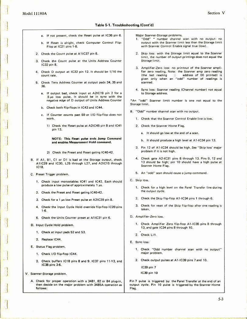
.. J
. J
.1
:. j
. 1
.. .. -. l
'. ]
]
Model 11180A Section V
Table 5-1. Troubleshooting. (Cont'd)
a. If not present, check the Reset pulse at IC36 pin 6 .
b. If Reset is alright, check Computer Control Flip· Flop at IC21 pins 1-6.
2. Check the Count pulse at A 1 IC37 pin 8 .
3. Check the Count pulse at the Units Address Counter IC32 pin 8 .
4. Check D output at IC32 pin 12. It should be 1/ 10 the count rate .
5. Check Tens Address Counter at output pads 34, 35 and 36.
a. If output bad, check input at A21C19 pin 2 for a . 5 µs low pulse. It should be in sync with the negative edge of D output of Units Address Counter
b. Check both flip-flops in IC43 and IC44.
c . If Counter counts past 50 or 1/0 flip-flop does not work .
1) Check the Reset pulse at A21C45 pin 8 and I C41 pin 13.
NOTE: This Reset pulse ends Jump Command and enables Measurement Hold command.
2) Check the Preset and Reset gating IC40-42.
B. If A1, 81, Cl or 01 is bad at the Storage output, check A 1 IC29 and IC30, L25 through L27, and A21C15 through IC18 .
C. Preset Trigger problem.
1. Check input monostables IC41 and IC42. Each should produce a low pulse of approximately 1 µs .
2. Check the Preset and Reset gating IC40-42.
3. Check for a 1 µslow Preset pulse at A21C20 pin 8.
4. Check· the Input Cycle Hold override flip-flop IC20 pins 1-6.
5. Check the Units Counter preset at A 1 IC31 pin 6.
D. Input Cycle Hold problem.
1. Check at input pads 52 and 53.
2. Replace IC44.
E. Status Flag problem.
1. Check 1/0 flip-flop IC44.
2. Check buffers IC18 pins 8 and 9. IC37 pins 11-13, and IC38 pins 3-6.
V. Scanner-Storage problem .
A. Check for proper operation with a 3481, 82 or 84 plug-in, then decide on the major problem with 3485A operation as follows:
Major Scanner-Storage problems. 1. "Odd" * number channel scan with no output: no
output with the Scanner limit less than the Storage limit with Scanner Control Enable signal true (low).
2. Skip loss: with the Storage limit equal to the Scanner limit, the number of output printings does not equal the Storage limit .
3. Amplifier-Zero loss : no printout of the Scanner amplifier zero reading. Note : the Scanner amp zero reading (the last reading address of 00 printed) is given only when an "odd" number of readings is scanned .
4. Sync loss: Scanner reading (Channel number) not equal to Storage address .
*An "odd" Scanner limit number is one not equal to the Storage limit.
B. "Odd" number channel scan with no output.
1. Check that the Scanner Control Enable line is low.
2. Check the Scanner Home Flag .
a. It shou Id go low at the end of a scan .
b. It should produce a high level at A 1-IC34 pin 13.
3 . Pin 12 of A1-IC34 should be high . See "Skip loss' major problem if it is not high .
4. Check gate A2-IC31 pins 8 through 13. Pins 9, 12 and 13 should be high; pin 10 should have a high pulse at Scanner Home Flag.
5. An "odd" scan should cause a jump command.
C. Skip loss.
1. Check for a high level on the Panel Transfer line during the output cycle .
2. Check the Skip flip-flop A 1-IC34 pins 1 through 6.
3 . Check for reset of the Skip flip-flop after one reading is taken.
D. Amplifier-Zero loss.
1. Check Amplifier Zero flip-flop A 1-IC35 pins 8 through 13, and gate IC34 pins 8 through 10.
2 . Check LI 1.
E. Sync loss:
1. Check "Odd number channel scan with no output" major problem.
2. Check output pulses at A 1-IC39 pins 7 and 10.
IC39 pin 7
IC39 pin 10
Pin 7 pulse is triggered by the Panel Transfer at the end of an output cycle. Pin 10 pulse is triggered by the Scanner Home Flag.
5-3

I '
:l
."J
:J
I ,
J 1J'
. . ' . , .. , . ' . ~ . ~
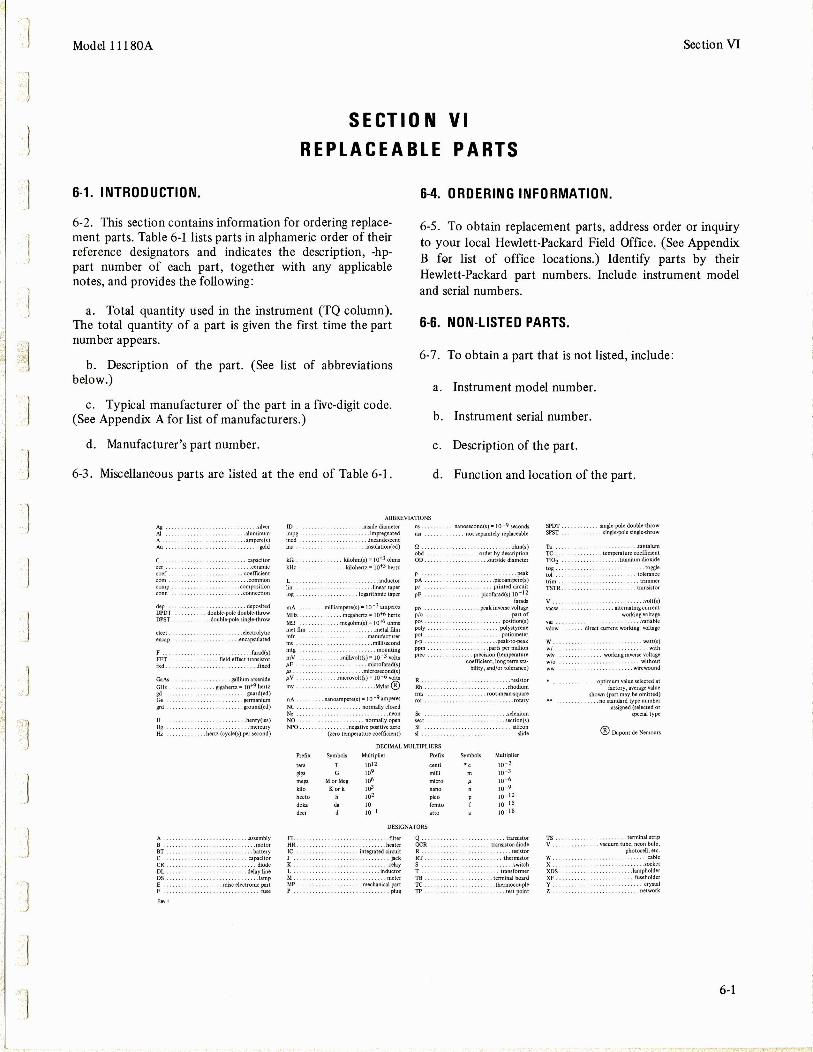
~:
.-.: ,.l
.l
,;;:1 :~;.~~
.]
.-J
. ] ....
· 1
'-"'] ,. J
J
']
Model l l 180A Section VI
SE CTI 0 N VI REPLACEABLE PARTS
6-1. INTRODUCTION.
6-2 . This section contains information for ordering replacement parts. Table 6-1 lists parts in alphameric order of their reference designators and indicates the description, -hppart number of each part, together with any applicable notes, and provides the following:
a. Total quantity used in the instrument (TQ column). The total quantity of a part is given the first time the part number appears.
b. Description of the part. (See list of abbreviations below.)
c. Typical manufacturer of the part in a five-digit code. (See Appendix A for list of manufacturers.)
d. Manufacturer's part number.
6-3. Miscellaneous parts are listed at the end of Table 6-1.
6-4. ORDERING INFORMATION.
6-5. To obtain replacement parts, address order or inquiry to your local Hewlett-Packard Field Office. (See Appendix B far list of office locations.) Identify parts by their Hewlett-Packard part numbers. Include instrument model and serial numbers.
6-6. NON-LISTED PARTS.
6-7. To obtain a part that is not listed, include:
a. Instrument model number.
b. Instrument serial number.
c. Description of the part.
d. Function and location of the part.
ABBREVIATIONS
Ag. .. silver Al .aluminum A. .ampere(s) Au. gold
capacitor cer. .. ceramic coef . . . . ....... coefficient com. . ... . . ... .. common comp . . .. composi tion
. . connection
dop . . deposited DPDT . . double-pole double-throw DPST. ... double-pole single-throw
elect. .electrolytic encap. . . .. encapsulated
F . . . farad(s) FET field effect transistor fxd . .... fixed
°""' .. . gallium arsenide
GHz .. : : : : ~-~henz ,. w+9 hertz gd . .. guard(ed) Ge .germanium .... .ground(ed)
H . . .. .. henry(ies) Hg. . ... . . mercury Hz ... hertz(cycle(s)persecond)
A . .. .. . assembly B . . motor BT. .. battery c ..... capacitor CR . ....... diode DL . . ... delayline DS. .... . ... tamp E ........ misc electronic part F . .. fuse
ID impg incd
ldl . kHz
L . \in . log.
..... insldediame1er .. . . impregnated
......... incandescent
. . . . . . . . .insulation(ed)
kilohm(s) = J0"'"3 ohms
. . kilohertz= 10+3 hertz
........ inductor . .. . . . linear taper
logarithmic taper
mA . . .. . milliampere(s)= 10 - 3 amperes
MHz . . . .. megahertz = I 0+-6 hertz
Mn . . megohm(s)"' 10+6 ohms metflm .. .. metalfilm mfr . .. manufacturer
............ . millisecond mtg ........................ mounting
mV . . .millivolt(s)= 10 - 3 volts µF . . ... microfarad(s) µs . . .......... microsecond(s) µV . . .microvolt(s)= 10 - 6 volts
my . . ...... . Mylar@
oA NC . No. NO. NPO.
.. .. nanoampere(s) = I o-9 amperes
.... normally closed . ........... . ..... neon
.............. normally open .. negative positive zero
(zero temperature coefficient)
. ... . ... .
n . obd OD.
p pA.
" pF
piv p/o .
'"' poly po• ,., ppm prec
R . Rh
" ·~· ~
•I
DECIMAL MULTIPLIERS
Prefix Symbols Multiplier Prefix
1012 centi
~ .. 10' milli
mo" Mor Meg 10• micro
kjJo Kor k 11>3 hecto h 10' pico .... .. 10 femto
deci 10- l
DESIGNATO RS
FL . .. filter Q . HR . . . . . heater QCR IC .. .. integratedcircuit R J . . . . . jack RT . K ........ .. .. . . . relay s L ..... inductor T M . meter TB. MP mechanical part TC. p ............... .. .. ........ plug TP
nanosecond(s) = 10 -9 seconds SPOT . .. . . single·pole double·throw
. . . not separately replaceable SPST .. . . .. .. single-polesingle·throw
.. ohm(s) T• . . . tantalum . .. . order by description TC. temperature coefficient ...... . outside diameter TI02 .. titaniu m dioxide
tog .. . .. . ... toggle . . . .. ... .. ... . . peak IOI . . tolerance
. .. .. picoampere(s) trim trimmer . . printed circuit
: :
0
picofarad(s) 10 - 12 TSTR. transistor
farads V . . .volt(s) .. peak inverse voltage .. alternating current
part of working voltage position(s) vu . .variable
polystyrene vdow direct current working voltage .potiometer
... . peak-to·peak w. .. watt(s)
.parts per million w/ .. . . with . . . .. . precision(temperature wiv . .. working inverse voltage
coefficient , longtermsta- w/o without bility,and/ortolerance) . . . ... . . wirewound
...... . .. .. .. . . resistor optimum value selected at .rhodium factory,averagevalu e
. .. . . root-mean-square shown (part may be omitted) ... rotary .no standard type number
assigned(selected or .selenium special t ype
... . .. .. section(s) ........ silicon
@ Dupont de Nemours . . .. ...... slide
Symbols Multiplier
., 10-2
10 - 3
10 - 6
10 -9
10 - 12
10 - 15
10 - 18
.. transistor TS .. terminal strip
. . transistor-diode V . ... .. . ~~c~~~ tube, neon bulb,
. . .. resistor photocell, etc .
thermistor W. ..cable
.switch x . . .. socket transformer XDS .. ..... ::. : :: iampholder
.. terminal board XF . . . .. . fuseholder
.. . thermocouple y .. .crystal .. test point z .. . . network
6-1

Section VI
T able 6-1. Re placeable Part s
Reference HP Part Number Oty Description Designation
Al 11180-66501 l BOARD ASSY:MAIN Al Cl 0160-0300 38 C : FXD MY 0. 0027 UF 2 00VDCW AlC 2 0160-0300 C:FXD MY 0 .0027 UF 20 0 VDCW AlC3 ')160-0300 C:FXD MY 0. 0027 UF 200VDCW AlC4 0160-0300 C : FXO MY 0 .00 27 UF 2 00 VDCW
AlC 5 ~160-03 00 C:FXD MY 0.0021 UF 200 VDCW AlC6 0160- 0300 C:F XD MY 0. 0027 UF 200 VDCW AlC7 0 160-0300 C :FXD MY 0. 0021 UF 2 OOVDCW AlC 8 0160- 0300 C :FXD MY 0 . 00 27 UF 200 VDCW AlC9 0 160-0300 C:FXD MY 0.00 21 UF 200VDCW
AlC 10 0 160-0300 C:FXD MY 0 .0021 UF 200 VOCW AlCll 0160-0300 C:F XD MY 0.002 7 UF 200VDCW AlC12 0 160-0300 C: FXD MY 0.002 7 UF 200 VDCW AlCl3 0160-0300 C:F XD MY 0 .0021 UF 200 VDCW AlC14 0160-0300 C:FXD MY 0 . 0 0 27 UF 200 VDCW
AlCl5 0160- 0 3 00 C : FXD MY 0. 0027 UF 200VDCW AlCl6 0160-0300 C:F XD MY 0. 0 0 21 UF 200 VDCW AlC17 0160- 0300 C : FXD MY 0. 0 021 UF 2 00VOCW AlCl8 0160- 0 300 C:F XD MY 0. 0 021 UF 200 VDCW AlC19 0160-0300 C:FXD MY 0.00 27 UF 2 00VOCW
AlC20 016 0- 0 300 C:FXO MY 0.0027 UF 200VDCW AlC21 0 160-0300 C:FXD HY 0. 0 0 27 UF 200VDCW AlC22 0160-0300 C:F XD MY 0.00 21 UF 200VDCW AlC23 0160-0300 C:F XD HY 0.00 27 UF 200 VDCW AlC24 0160-0300 C:F XO MY 0. 002 7 UF 20 0VDCW
AlC25 01 60-030 0 C:FXD MY 0. 0021 UF 200VDCW AlC 2 6 0160-0300 C : F XD MY 0 .0021 UF 200VDCW Al C27 0 160-0300 C : FXD MY 0 . 0 021 UF 2 0DVDCW AlC 28 0160-0300 C: F XD MY 0. 00 21 UF 200 VDCW AlC29 0160-0300 C : FXO MY 0.00 21 UF 200VDCW
AlC 30 0 160-0300 C: F XD MY 0.0027 UF 200VDCW AlC31 0160-0300 C:FXD MY 0.0021 UF 200VDCW AlC3 2 0 160-0300 C:FXD MY 0.0021 UF 200VDCW AlC3 3 0160-0300 C:FXD MY 0. 0027 UF 200VDCW AlC34 0 1 80-1701 3 C:FXO ELECT 6.8 UF 2oi 6VDCW
AlC3 5 01 80-0197 l C:FXD ELECT 2 .2 UF 101: 20VDCW Al C36 01 5 0-006 4 1 C:F XD CER 0.1 UF +60% - 20% l OOVD CW AlC37 0 160-0161 1 C: FXD MY 0.01 UF l Og 20 0VOCW AlC38 0 160-0157 1 C:F XO HY Q.00 47 UF l Oi 200VDCW AlC 39 0 160-0153 C : FXD HY 0 .001 UF 101: 20 0VDCW A 1 C4 0 01 6 0 - 0 99 0 1 C: FXD MICA 1 0 0 PF 2% 3 0 0 VDCW AlC41 0 160-2 9 6 4 2 C:FXD CER DISC 0.01 UF + 60 - 20% 25VDCW AlC4 2 0160-015 3 11 C :F XD MY 0.001 UF 10% 200 VDCW AlCRl 19 01-0040 4 DIOOE: SILI CON 30MA 30HV All Cl 1820- 0728 12 IC:DI GITAL TTL + LOGIC AllC2 1820-0728 IC:OIGITAL TTL + LOGIC
AllC3 1820-072 8 IC :DIGITAL TTL + L OGIC AllClt 1820-0728 IC : DIGITAL TTL + L OGIC AllC5 1820-0728 IC:DIGITAL TTL + LOGIC AllC6 1820-072 8 IC:DIGITAL TTL + LOGIC AllC7 1820-072 8 IC :DIGITAL TTL + LOGIC
AllC8 182 0-0728 IC : OIGITAL TTL + LOGIC AllC9 1820-072 8 IC :D IGITAL TTL + LOGIC All C 10 1820-0728 IC:DIGITAL TTL + LOGIC AllCll 1820-072 8 IC :DIGITAL TTL + LOGIC Al1 Cl2 1820-0728 IC:DIGITAL TTL + LOGIC
Al1 Cl3 1820-03"9 20 IC : DTL QUAD 2-INPT NANO GATE AllCllt 1820-0349 1c :on QUAD 2-INPT NANO GATE Al1Cl5 1820-0349 IC:OTL QUAD 2-INPT NANO GATE All C 16 1820-0349 IC : DTL QUAD 2- INPT NANO l;ATE All Cl 7 1820-0349 IC:OTL QUAD 2-INPT NANO GATE
All C 18 1820-0349 IC : DTL QUAD 2- INPT NANO GATE
' Al1 Cl9 1820-0349 IC :OTL QUAD 2-INPT NANO GATE All C20 1820-0349 1c:on QUAD 2-INPT NANO GATE AllCZl 1820-0349 IC:DTL QUAD 2-INPT NANO GATE AllC22 1820-0349 IC : DTL QUAD 2-INPT NANO GATE
AllC23 18 20-0349 IC:DTL QUAD 2-lNPT NANO GATE All C24 1820-0349 IC:OTL QUAD 2- l NPT NANO GATE All C25 1820-0349 IC:DTL QUAD 2- INPT NANO GATE AllC26 1820-0349 1c :on QUAD 2-INPT NANO GATE All CZ 7 18 20-0349 l C :DTL QUAD 2- INPT NANO GATE
A l! C 28 1820-0349 1c :on QUAD 2- INPT NANO GAT E All C29 1820-0349 1c :on QUAD 2-I NPT NANO GATE All C30 1820-0349 I C :OTL QUAD 2- INPT NANO GATE AU CH 1820- 0586 6 IC: OI GITAL TTL HEX CON VE RTER All C32 18 20-0322 1 IC : TTL DECADE DIVIDER
See i ntroductio n to this sec tio n fo r order ing informatio n
6-2
Mfr Code
2 8480 56 28 9 56289 562 89 5628 9
56289 56289 56 289 56 28 9 56289
56289 56289 56 289 562 89 56 28 9
56289 56289 562 89 56 28 9 56289
56 289 562 89 56 289 56289 56 289
56 289 56289 562 89 56 28 9 56 289
56 289 562 89 56 289 56289 284 8 0
5628 9 7 2962 5628 9 56289 5 6289 00 6 5 3 7 29 62 5 62 69 0 7 263 284 80 2848 0
2848 0 28480 284 80 281t 8 0 2 84 80
28480 2 84 8 0 2848 0 2848 0 2848 0
0129 5 01295 0 1 29 5 0129 5 01295
01295 01 295 01295 01295 01295
01295 01295 01295 01295 0129 5
01 29 5 0 1295 0 1295 28480 56"289
Model 11180A
Mfr Part Number
11180-66501 l 92P27292 - PT S l 92P27 292-PTS l92P2 7 29 2-PT S l 92P27 292-PT S
l 92 P272 92-PTS l92P27292 - PTS l 92P2 72 92 -PTS 192P27292-PT S 192P 272 92 -PTS
l 9 2P27292- PT S l 92 P2 72 92 -PTS l92P27292 - PT S l 9 2P272 9 2-PTS l92P27292-PTS
l92P272 92-PT S l 92P27292-PTS l 92P 27292-PT S 192P2 7292 - PTS l 92P2 72 92 -PTS
l 92P2 7292-PTS l92P2729 2-PT S l92P2 72 9 2-PTS l 92P 2 7 29-2 -PTS 192P2729 2-PTS
192P27292-PT S 192P27292 -PTS 192P27292-PT S 192P27292-PTS 192P2 72 92 -PT S
l 92P 2 7 292 -PT S 192P27292-PTS 192P 2 729 2-PT S l92P2 72 92 -PT S 0180-1701
150D2 25X9 02 0 A2-DY S 6 1 31 - 100 -6 51-1042 l 92 Pl0392 - PTS l 9 2P4 7292-PTS 192Pl0292-PTS
RDM15F101G3S 5635-000-Y5UD-103Z 19 2 P102 92 -PT S FDG1 088 1 820-07 28 1820-0728
1 820-0728 1820-072 8 1820-072 8 1820-0728 1820-0728
1820-072 8 1 820-0728 1820-0728 18 20-072 8 18 20-072 8
SN150 31 SN15031 SN15031 SN15031 SN15031
SN15031 SN15031 SN15031 SN15031 SN15031
SN15031 SN150 3 1 SN1503l 5'1 150 31 SN1503l
SN15031 SN15031 SN15031 1 820-05 86 N8280A
:l
~ .J
·].· ' .
']
]

· 1 Mode l 11180A Section VI
Table 6-1. Re placeable Parts (Cont ' d)
Reference HP Part Number Oty Description Mfr Mfr Part Number Designation Code
--] All C33 1820-0307 l IC:OIGITAL OTL HEX INVERTER 28480 1820-0307 AllC34 1820-0349 IC:DTL QUAD 2-INPT NANO GATE 0 129 5 SN15031 Al!C35 1820-0349 IC:OTL QUAD 2-!NPT NANO GATE 01295 SN15031 AllC36 1820-0586 !C:OIG!TAL TTL HEX CONVERTER 28480 1820-0586 Al!C37 1820-0583 11 IC:TTL QUAO 2-INPT NANO GATE 28480 1820-0583
A 11 C38 1820- 0583 IC:TTL QUAD 2-!NPT NANO GATE 28480 1820-05 83
·l Al1C39 1820-0730 l IC:O!GITAL TTL + LOGIC 28480 1820-0730 Alli 9100-3222 38 CO IL: FXO 100 UH 28480 9100-3222 Al l2 9100-322 2 COIL:FXO 100 UH 28480 91~0-3222
All3 9100-3222 CO IL: FXO 100 UH 28480 9 100-32 22
All4 9100-3222 COIL:F XO 100 UH 28480 9100-3222 Al l 5 9100-3222 COIL:FXO 100 UH 28 4 80 9100-3222 All6 9100-3222 COIL:FXD 100 UH 28480 9100-3222 All7 9100-3222 COIL:FXD 100 UH 28480 9100-3222 All 8 9100-3222 COIL:FXD 100 UH 2848 0 9100-3222
All9 9100-322 2 COIL:FXD 100 UH 28480 9100-3222
----·_ \ :~~ AlllO 9100-3222 CO!L:FXD 100 UH 284 80 9100-3222 Alli l 9100-3222 CO!L:FXO 100 UH 28480 91 00-3222 All 12 91('0-3222 CO!L:FXD 100 UH 28480 9100-3222 Alll3 9100-3222 COIL:FXD 100 UH 28480 9100-32 22
Alll4 9100-3222 COIL :FXO 100 UH 28480 9100-3222 Alll5 9100-3222 COIL:FXD 100 UH 28480 9100-3222
. ·_ 1 Alll6 9100-3222 COILIFXO 100 UH 28480 9100-3222 Alli 7 9100-3222 CO IL: FXD 100 UH 28480 9100-3222 Alll8 9100-3222 COIL•FXD 100 UH 2 8480 9100-322 l
Alll9 9100-3222 COIL:FXD 100 UH 28480 9100-3222 All20 9100-3222 CO!LIFXD 100 UH 28480 9100-3222
--J
All21 9100-3222 COILIFXD 100 UH 28480 9100-3222 All22 9100-3222 CO!LIFXD 100 UH 28480 9100- 3222 All23 9100-3222 COIL:FXD 100 UH 28480 9100-3222
All24 9100-3222 CO!L:FXD 100 UH 28480 9100-3222 All2 5 9100-3222 COIL:FXO 100 UH 28480 9100-3222 All26 9100-3 222 CO!L:FXD 100 UH 28480 9100-322 2 All27 9100-3222 CO IL: FXD 100 UH 28480 9100-3222 All28 9100-3222 COIL:FXO 100 UH 2848 0 9100-3222
All29 9100-3222 CO IL: FXD 100 UH 28480 9100-32 22 All30 9100-3222 COIL:FXD 100 UH 2 84 80 9100-3222 All31 9100-3222 COIL:FXD 100 UH 28480 9100- 3222
] All32 9100-3222 COIL:FXD 100 UH 28480 9100-3222 All33 9100-3222 COIL:FXO 100 UH 28 480 9100-3222
All34 9100-3223 39 COIL:FXO 220 UH 2848 0 9100-3223 All35 9100-3223 COIL:FXD 22 0 UH 28480 91 00-3223 All36 9100-3223 COIL:FXD 220 UH 28480 9100-3223 All37 9100-3223 COIL :FXO 220 UH 28480 9100-3223 All38 9100-3223 COIL :FXD 220 UH 28480 9100-3223
Allll 1990-0312 3 TSTR:PHOTO 28480 1990-0312 All12 1990-0312 TSTR:PHOTO 28480 1990-03 12 All13 1990-0312 TSTR:PHOTO 28480 1990-0312 AlQl 1854-0042 2 TSTR:SI NPN 28480 1854-0042 AlQ2 1854-00't2 TSTR:SI NPN 28480 1854-0042
AlQ3 l85't-007l 9 TSTR :SI NPN I SELECT ED FR OM 2N3704) 28480 1 854-00 71 Al~4 1854-0071 TSTR:SI NPNISELECTED FROM 2N3704l 28480 1854-0071 AlQ5 185"-0071 TS TR : SI NPNISELECTED FROM 2N3704) 2 84 80 1854-0071 AlQ6 18 5't- 007l TSTR:SI NPNI SELECTED FROM 2N3701tl 28480 1854-0071 AlQ7 1854- 0071 TSTR: Sl NPNISELECTED FROM 2N3704) 28480 1854-0071
AlQ8 1854-0071 TSTR :S l NPNISELECTED FROM 2N370't) 284 80 1854-0071 AlQ9 1853-0010 l TSTR:SI PNPISELECTED FROM 2N325ll 28480 1853-0010 AIU 068't-l 021 1 6 R:FXO COMP 1000 OHM lOi 1/4W 01121 CB 1021 AlR2 0757-04't2 2 R:FXD MET FLM 10.0K OHM ti l/8W 28480 0757-0442
J AU3 0757-0't42 R:FXD MET FLM 10.0K OHM ti l/8W 28480 0757-0442
AlR4 068't-l021 R:FXD COMP 1000 OHM lOi l/4W 01121 CB 1021 AH5 0684-2231 5 R:FXO COMP 22K OHM lOi l/4W 01121 CB 2231 AlR6 0684-1021 R:FXD COMP 1000 OHM lOi l/4W 01121 CB 1021 AH7 0684-1021 R: FXD C~MP 1000 OHM lOi l/4W 01121 CB 1021 AlR8 068't-l021 R:FXD COMP 1000 OHM lOi l/4W 01121 CB 1021
Al ~9 0 684-1811 2 R•FXD COMP 180 OHM lOi l/4W 01121 CB 1811 AlRlO 0684 - 1021 R: FXD C 0 MP 100 0 OHM 1 0% 1 / 4 W 0 11 21 CB 102 1 AlRll 0684-2231 R:FXO COMP 22K OHM lOi l/4W 0 11 21 CB 2231 AlRl2 06B4-1031 R: FXO C014P 1 0 KOHM lOi l/4W 0 11 21 CB 10 3 1 AlRl3 068't-1021 R:FXO COMP 1000 OHM lOi l/4W 01121 CB 1021
AlRl't ~6 84-1021 R:FXO COMP 1000 OHM lOi l/4W 01121 CB 1 0 21 AlR15 0684-3911 l R:FXO COMP 390 OHM lOi l/4W 01121 CB 3911 AlR16 068 4-3311 3 R :FXD COMP 330 OHM 10i l /4W 01121 CB 3311 AlR17 0684-2221 " R:FXD CO~P 2200 OHM lOi l/4W 01121 CB 2221 AlR18 0684-2221 R:FXD COMP 2200 OH M lOi l /4W 01121 ca 2221
See introduction to this section for ordering information
6-3

Section VI
I
Reference Designation
AlR19 AlR20 AH21 AlR22 AH23
All All All All All
All AZ A2Cl A2C2 A2C3
A2C~ A2C5 A2Cb A2C7 A2C8
A2C9 A2Cl0 A2Cll A2Cl2 A2Cl3
A2Cl4 A2Cl5 A2Cl6 A2Cl 1 A2Cl8
A2Cl9 A2C20 A2C21 A2C22 A2CR1
A2CR2 A2CR3 A2C~4
A2CR5 A2C~6
A2CR7 AZ I Cl A2IC 2 A21C3 A2!C4
A21C5 A21Cb A21C7 A21C8 A21C9
A21C10 A21C11 A21C12 A21Cl3 A2IC 14
A21Cl5 A2IC lb A21Cl7 A2IC 18 A21Cl9
A21 C20 A2IC21 A21C22 A21C23 A2IC24
A21C25 A21C 2b A21C27 A2IC28 A21C29
A21C30 A21C31 A2!C32 A21C33 A21C 34
6-4
HP Part Number
0684-1531 0684-2221 0684-1811 0684-2231 0684-2 231
0363-0058 1200-0437 1200-0449 1200-0450 4040-0748
4040-0753 11180-66502 0180-0309
0180-1701
0160-0153 0180-1701 0160-0153 0160-0153 0160-0153
0160-0153 0160-0153 0150-0055 0150-0055 0160-0300
0160-0300 0160-0300 0160-0300 0160-0300 0160-2964
0160-0153 0160-0298 0160-0153 0160-0153 1901-0045
1901-0045 1901-0040 1902-3073 1902-3073 1901-0040
1901-0040 1820-0584 1820-0584 18 20-0 584 1820-0584
1820-0 584 1820-0584 1820-0174 1820-0584 1820-0584
1820-0174 1820-0584 1820-0584 1820-0 584 1820-0584
1820-0174 1820-0584 1820-0584 1820-0174 1820- 0586
1820-0583 18 20-0 0 5 4 1820-0583 1820-0590 1820-0588
1820-01 74 1820-0054 1820-0583 1820-0587 1820-0586
1820-0591 1820-0588 1820-0583 1820-0583 1820-0584
Oty
2 12 72
2 1
15
4
Table 6- 1. Replacement Parts (Cont'd)
Description
R:FXD COMP 15K OHM lOl l/4W R:FXD COMP 2200 OHM lOl l/4W R:FXD COMP 180 OHM lOi l/4W R:FXD COMP 22K OHM lOl l/4W R:FXD COMP 22K OHM lOl l/4W
CONTACT:ELECT. 0.700" LG SOCKET:IC 8 PIN SOCKET:IC 14 CONTACT SOCKET:IC 16 CONTACT EXTRACTOR:PC BOARD, BLACK
EXTRACTOR:PC BOARD, GREEN BOARD ASSY:PIG C:FXO ELECT 4.7 UF 20l lOVDCW NOT ASSIGNED C:FXD ELECT 6.8 UF 20l 6VDCW
C:FXD MY 0.001 UF lOl 200VDCW C:FXD ELECT 6.8 UF 20l 6VOCW C:FXO HY 0.001 UF IOl 200VDCW C:FXO MY 0.001 UF lOl 200VDCW C:FXD MY 0.001 UF lOl 200VDCW
C:FXD MY 0.001 UF !Ol 200VDCW C:FXD MY 0.001 UF lOl 200VDCW C:FXO Tl DIOXIDE 10 PF 5l 500VDCW C:FXD Tl DIOXIDE 10 PF 5l 500VDCW C:FXD MY 0.0027 UF 200VDCW
C:FXO MY 0.0027 UF 200VDCW C:FXD MY 0.0027 UF 200VDCW C:FXO MY 0.0027 UF 200VDCW C:FXD MY 0.0027 UF 200VDCW C:FXD CER DISC 0.01 UF +80-20l 25VDCW
C:FXD MY 0.001 UF lOl 200VDCW C:FXD MY 0.0015 UF lOl 200VDCW C:FXD MY 0.001 UF lOl 200VDCW C:FXD MY 0.001 UF lOl 200VDCW DIOOE:SILICON 0.75A lOOPIV
OIOOE:SJLICON 0.75A lOOPIV OIOOE:SJLICON 30MA 30WV DIODE BREAKOOWN:4.32V 5l DIODE BREAKDOWN:4.32V 5l OIOOE:SJLICON 30MA 30WV
DIOOE:SILICON 30MA 30WV IC:TTL QUAD 2-INPT NOR GATE IC:TTL QUAD 2-INPT NOR GATE JC:TTL QUAD 2-INPT NOR GATE IC:TTL QUAD 2-INPT NOR GATE
JC:TTL QUAD 2-INPT NOR GATE IC:TTL QUAD 2-INPT NOR GATE INTEGRATED CIRCUIT:TTL HEX INVERTER JC:TTL QUAD 2-INPT NOR GATE JC:TTL QUAD 2-INPT NOR GATE
INTEGRATED CIRCUIT:TTL HEX INVERTER JC:TTL QUAD 2-INPT NOR GATE IC:TTL QUAD 2-INPT NOR GATE JC:TTL QUAD 2-INPT NOR GATE IC:TTL QUAD 2-INPT NOR GATE
INTEGRATED CIRCUJT:TTL HEX INVERTER JC:TTL QUAD 2-INPT NOR GATE IC:TTL QUAD 2-INPT NOR G~TE INTEGRATED CIRCUIT:TTL HEX INVERTER IC:OJGITAL TTL HEX CONVERTER
IC:TTL QUAD 2-INPT NANO GATE JC:TTL QUAD 2-INPT NANO GATE IC:TTL QUAD 2-INPT NANO GATE IC:OIGITAL TTL DUAL 2-WIOE,JNPT AND/OR JC:TTL DUAL 4-INPT NANO GATE
INTEGRATED CIRCUJT:TTL HEX INVERTER IC:TTL QUAD 2-INPUT NANO GATE IC:TTL QUAD 2-INPT NANO GATE IC:TTL TRIPLE 3-INPT NANO GATE JC:OJGITAL TTL HEX CONVERTER
IC:TTL INPT ANO-OR-INVERT GATE IC:TTL DUAL 4-INPT NANO GATE IC:TTL QUAD 2-INPT NANO GATE IC:TTL QUAD 2-INPT NANO GATE IC:TTL QUAD 2-INPT NOR GATE
See introduction to this section for ordering information
Mfr Code
01121 01121 01121 01121 01121
91662 17117 17117 17117 28480
28480 28480 56289
28480
562 89 28480 562 89 56289 562 89
56289 562 89 78488 78488 56289
562 8 9 562 89 56289 56289 7298 2
56289 56289 56289 562 89 04713
04713 07263 04713 04713 07263
07 263 28480 28480 28480 28480
28480 28480 01295 28480 28480
01295 28480 28480 28480 28480
01295 28480 28480 01295 28480
28480 0 129 5 28480 28480 28480
01295 01295 28480 28480 28480
28480 28480 28480 28480 28480
Model 11180A
Mfr Part Number
CB 1531 CB 22 21 CB 1811 CB 2231 CB 2231
02-005-12 0-612 5 5566-235-5 7014-295-5 7016-295-5 4040-0748
4040-0753 11180-665 02 1500475X0010A2-0YS
0180-1701
l 92Pl 0292-PTS 0180-1701 l 92Pl0292-PTS l 92Pl0292-PTS 192Pl0292-PTS
192Pl0292-PTS l 92Pl 0292-PTS TYPE GA TYPE GA 192P27292-PTS
192P27292-PTS 192P27292-PTS 192P27292-PTS l92P27292-PTS 5835-000-Y5UO-l03Z
l92Pl0292-PTS l 92P 15292-PTS 192Pl0 292 -PTS 192Pl0292-PTS SR1358-7
SR1358-7 FOG1088 sz 10939-77 sz 10939-77 FOG1088
FOG1088 1820-0584 1820-0584 1820-0584 1820-0584
1820-0584 1820-0584 SN8199 1820-0584 1820-0584
SN8199 1820-0584 1820-0584 1820-0584 1820-0584
SN8199 1820-0584 1820-0584 SN8199 1820-0586
1820-0583 SN 4342 1820-0583 1820-0590 1820-0588
SN8199 SN4342 1820-0583 1820-0587 1820-0586
1820-0591 1820-0588 1820-0583 1820-0583 1820-0584
l .. ]
J
]
·]
]
J J

Model 11180A Section VI
Table 6-1. Replaceable Parts (Cont'd)
Reference HP Part Number Oty Description Mfr Mfr Part Number Designation Code
···1 •,
A2lc35 1820-0595 2 !C:TTL DUAL J-K MASTER SLAVE F/F 28480 1820-0595 AZIC36 1820-0537 1 JC:TTL DUAL 4-INPT NANO GATE 28480 1820-0537 AZIC37 1820-0583 JC:TTL QUAD 2-INPT NANO GATE 28480 1820-0583 AZ! C38 1820-0587 JC:TTL TRIPLE 3-JNPT NANO GATE 28480 1820-0587 AZ!C39 1820-0207 1 !C:TTL MONOSTABLE MULTIVIBRATOR 28480 1820-0207
A2JC40 1820-0587 JC:TTL TRIPLE 3-INPT NANO GATE 28480 1820-0587 A21C41 1820-0583 JC:TTL QUAD 2-INPT NANO GATE 28480 1820-0583 AZIC42 1820-0586 JC:DJGJTAL TTL HEX CONVERTER 28480 1820-0586 AZIC43 1820-0076 1 IC:TTL DUAL MASTER/SLAVE FF 01295 SN4355 AZIC44 1820-0595 JC:TTL DUAL J-K MASTER SLAVE F/F 28480 1820-0595
A2IC45 1820-0588 JC:TTL DUAL 4-INPT NANO GATE 28480 1820-0588 A2JC46 1820-0587 JC:TTL TRIPLE 3-INPT NANO GATE 28480 1820-0587 AZIC47 1820-0586 JC:DIGITAL TTL HEX CONVERTER 28480 1820-0586 A21C48 1820-0583 IC:TTL QUAD 2-INPT NANO GATE 28480 1820-0583 A2ll 9100-3223 COIL:FXO 220 UH 28480 9100-3223
A2L2 9100-3223 COIL:FXO 220 UH 28480 9100-3223 AZL3 9100-3223 COJL:FXD 220 UH 28480 9100-3223 AZL4 9100-3223 COIL:FXD 220 UH 28480 9100-3223 AZL5 9100-3223 COIL: FXD 220 UH 28't80 9100-3223 AZL6 9100-3223 CO ll:FXD zzo UH 28480 9100-3223
A2L 7 9100-3223 COIL :FXD 220 UH 28480 9100-3223
.·. J
A2L8 9100-3223 COIL:FXD 220 UH 28480 9100-3223 AZL9 9100-3223 COIL :FXD 220 UH 28480 9100-3223 AZLlO 9100-3223 COIL:FXD 220 UH 28480 9100-3223 AZLll 9100-3223 COJL:FXD 220 UH 28480 9100-3223
AZLlZ 9100-3223 COIL:FXD 220 UH 28480 9100-3223 AZL13 9100-3223 COIL:FXD 220 UH 28480 9100-3223 AZL14 9100-3223 COIL:FXD 220 UH 28480 9100-3223 A2ll5 9100-3223 COIL:FXD 220 UH 28480 9100-3223 A2ll6 9100-3223 COIL:FXD 220 UH 28480 9100-3223
AZLl 7 9100-3223 COIL:FXD 220 UH 28480 9100-3223 A2Ll8 9100-3223 COJL:FXD 220 UH 28480 9100-3223
. J A2Ll9 9100-3223 COIL:FXD 220 UH 28480 9100-3223 AZL20 9100-3223 COIL:FXD zzo UH 28480 9100-3223 AZLZl 9100-3223 COIL:FXD 220 UH 28480 9100-3223
AZL22 9100-3223 COIL:FXD 220 UH 28480 9100-3223 A2L23 9100-3223 COIL:FXD 220 UH 28480 9100-3223
· 1 AZL24 9100-3223 COIL:FXD 220 UH 28480 9100-3223 AZL25 9100-3223 COIL:FXD 220 UH 28480 9100-3223 AZL26 9100-3223 COIL:FXD 220 UH 28480 9100-3223
AZL27 9100-3223 COIL:FXD zzo UH 28480 9100-3223 A2L28 9100-3223 COJL:FXD 220 UH 28480 9100-3223 A2L29 9100-3223 COIL:FXD 220 UH 28480 9100-3223
_] A2L30 9100-3223 COIL:FXD 220 UH 28480 9100-3223 A2L31 9100-3223 COIL :FXD 220 UH 28480 9100-3223
AZL32 9100-3223 COIL:FXD 220 UH 28480 9100-3223 A2L33 9100-3223 CO!l:FXD 220 UH 28480 9100-3223 A2L34 9100-3222 COIL:FXD 100 UH 28480 9100-3222 A2L35 9100-3222 COIL:FXD 100 UH 28480 9100-3222 A2L36 9100-3222 COIL:FXD 100 UH 28480 9100-3222
A2L37 9100-3222 COIL: FXD 100 UH 28480 9100-3222 A2L38 9100-3222 COIL:FXD 100 UH 28480 9100-3222 AZL39 9100-3223 COIL:FXD 220 UH 28480 9100-3223 A2Ql 1854-0071 TSTR:SJ NPNC SELECTED FROM 2N3704J 28480 1854-0071 A2Q2 1854-0071 TSTR:SI NPNCSELECTED FROM 2N3704l 28480 1854-0071
A2Q3 1854-0071 TSTR:SJ NPNCSELECTED FROM 2N3704J 28480 1854-0071 A2Rl 0684-4 711 1 R:FXO COMP 470 OHM lOi l/4W 01121 CB 4711 A2RZ 0684-6821 16 R:FXD COMP 6.8K OHM 10i.l/4W 01121 CB 6821 AZR3 0684-6821 R:FXD COMP 6.8K OHM lOi l/4W 01121 CB 6821 A2R4 0684-6821 R :FXD COHP 6 .SK OHH lO:S l /4W 01121 CB 6821
AZR5 0684-6821 R:FXD COHP 6.8K OHH lOi l/4W 01121 CB 6821 A2~b C684-6821 R:FXD COHP 6.8K OHH loi l/4W 01121 CB 6821 A2R7 0684-6821 R:FXD COHP 6.BK OHH loi l/4W 01121 CB 6821 A2R8 0684-6821 R•FXO COHP 6.8K OHH loi l/4W 01121 CB 6B21 A2R9 0684-6B21 R:FXD COHP 6.8K OHH loi l/4W 01121 CB 6821
A2Rl0 06B4-1021 R:FXO COHP 1000 OHM lO:l l/4W 01121 CB 1021 A2Rll 0684-1021 R:FXD COHP 1000 OHH 10i l/411 01121 CB 1021 A2U2 0684-1021 R:FXD COMP 1000 OHH loi 11411 01121 CB 1021 AZR13 0684-1021 R:FXD COHP 1000 OHH 10i 1/411 01121 CB 1021 A2Hlt 0684-1021 R:FXD COHP 1000 OHH 10i l/4W 01121 CB 1021
A2Rl5 0684-1021 R:FXD COMP 1000 OHH loi l/4W 01121 CB 1021 AZR16 0684-1021 R•FXD COHP 1000 OHM loi l/4W 01121 CB 1021 AZRl 7 068't-2221 R:FXD COMP 2200 OHM loi 1/411 01121 CB 2221 A2Rl8 0684-1 Bltl 2 R:FXD COHP 180K OHM loi 1/411 01121 CB 1841 AZR19 0684-1841 R:FXD COHP 180K OHM 10i l/4W 01121 CB 1841
See introduction to this section for ordering information
6-5
r 1

Section VI Model 11180A l Table 6-1. Replaceable Parts (Cont'd)
Reference HP Part Number Oty Description Mfr Mfr Part Number Designation Code l A2R20 0684-6821 R:FXD COMP 6.BK OHM 10% l/4W 01121 CB 6821 A2R21 0684-6821 R:HO COMP 6.8K OHM lOt l/4W 01121 CB 6821 A2R22 0684-6821 R:FXO COMP 6.8K OHM lOt l/4W 01121 CB 6821 A2R23 0684-3311 R:FXD COMP 330 OHM lOi l /4W 01121 CB 3311 J A2R24 0757-0449 l R:FXO FLM 2DK OHM 1% l/8W 28480 0757-0449
A2R25 0684-6821 R:FXO COMP 6.8K OHM 10% l/4W 01121 CB 68 21 A2R26 NOT ASSIGNED A2R27 NOT ASSIGNED A2R2B 0684-3311 R:FXO COMP 330 OHM 10% l/4W 01121 CB 3311 ] A2R29 ()684-6821 R:FXO COMP 6.BK OHM 10% l/4W 01121 CB 6821
A2R30 0684-6821 R:FXD COMP 6.BK OHM 10% l/4W 01121 CB 6821 A2R31 0684-1031 2 R:FXO COMP lOK OH~ 10% l /4W 01121 CB 1031 A2R32 0684-1021 R:FXO COMP 1000 OHM 10% l/4W 01121 CB 1021 A2R33 0684-1031 R:FXD COMP lOK OHM l 0% l /4W 01121 CB 1031 A2RH 0684-6821 R:FXD COMP 6.BK OHM lOi l/4W 01121 CB 6B21
A2R35 0684-6821 R:FXO COMP 6.8K OHM 10% l/4W 01121 CB 68 21 A2 0363-0058 CONTACT:ELECT. 0.700" LG 91662 0 2-00 5-120-6125 AZ 1200-0449 SOCKET:IC 14 CONTACT 1711 7 7014-295-5 A2 1200-0450 SOCKET:IC 16 CONTACT 17117 7016-295-5
111 B0-61601 l LEAD ASSY 28480 11180-61601
11180-01201 2 ADAPTER:PLATE 28480 l llB0-01201 1251-0218 2 CONNECTOR:LOCK POST SUBMINAT TYPE 0 71468 053018 1251-2570 65 CONTACT: R t P CONNECTOR, MALE 71468 031-9540-000 1251-2976 l CONNECTOR:R t P,100 MALE CONTACT 71468 200100P-FO
J J
J
J J
See introduction to this section for ordering information
6-6 .J

. ]
· 1
' J
.J
·]
J
Model l l l 80A Section VII
SECTION VII CIRCUIT DIAGRAMS
7-1. INTRODUCTION. b. Component values are shown as follows unless otherwise noted:
7-2. This section contains the schematic diagrams of the two l l l 80A assemblies and eight signal flow diagrams illustrating subcircuit operation.
Capacitance in µF Resistance in ohms Inductance in µH
7-3. NOTES c. * Average value shown. Optimum value selected at factory.
d. -- - - Denotes assembly a . . Partial reference designators are shown within
assembly outlines. Prefix these with assembly number for complete designator. e. -----Heavy line denotes main signal path.
REFERENCE DESIGNATIONS ASSEMBLY ASSEMBLY
REFERENCE ASSEMBLY PART NUMBER DESIGNATION NAME (INCLUDES A2A/ SUBASSEMBLY) r--"---, ~ ~
JACK XA2 IS MOUNTED ON A2 POWER SUPPLY (OOXXX-66501)
PLUG Pl IS MOUNTED ON ASSEMBLY OR IS PART CHASSIS OR ANOTHER ASSEMBLY~
/VOF THE ASSEMBLY BOARD (COMPLETE DESIGNATOR IS A2PI)
~ 2 t--p'---.
:, I Pl IS NOT MOUNTED ON A2 ASSEMBLY : (COMPLETE DESIGNATOR IS Pl) •
R3 TEST VOLTAGE~
+2.92V
QI
I DENOTES SIGNAL I CONNECTION
"'\ l I ,.,.,,-vCOMPLETE DESIGNATOR IS A2R4
R4
SUBASSEMBLY OF A2 --4< ~<-+!'--........_.: ( 4 ~--'
-1< ~ I ~NUMBER INDICATES
,-v(COMPLETE DESIGNATOR IS A2A/)
1'----P1~3~2 I DENOTES S£EMATIC
ON WHICH CONNECTION I /S MADE
PIN OF XA2 AND Pl
I ~ IB
WIRE COLOR: COLOR COD?, THE SAME I ~ AS THE RESISTOR COLOR CODE. FIRST EYELET OR STANDNUMBER INDICATES BASE COLOR SECOND I OFF TERMINAL, MAY OR NUMBER INDENT/FIES WIDER STRIP, AND I MAY NOT BE NUMBERED THE THIRD INDICATES THE NARROWER I L(f9" A>' STRIP. (~DENOTES WHTIREDIYEL WIRE) I ,/; 8
Al fPHOTO:CHOPPER osc-1
I I I RI R2 I I ~ I I COMPLETE I
DESIGNATOR /S A2A/RI
I I
6 >I ,g
M,/ILE STANDa5{; ~FEMALE PIN PIN CONNECTOR CONNECTOR ON
MAY OR MAY ....rtI: A WHT/ RED WIRE NOT BE NUMBERED ,,rJW-/
~('.j....-'
rL PARTIAL REFERENCE DESIGNATIONS ARE SHOWN: PREFIX WITH ASSEMBLY OR SUBASSEMBLY
DESIGNATION(S) OR BOTH FOR COMPl:..ETE DESIGNATION STO-B-2192
7-1

I -:]
:·: l :]
·]
JI
J
. ~· - 1

ICBD
Figure 7-1. Isolated BCD .
i-···· i i
..r.:J"-++-+o«·I'-,_._" .. -.... -••• -.... --= ... ____.: i ·-· - ... i
•F-+--="-'·-H--...... -+-+------.l~···-1
~-~-+>i •• , I
b-f---'='--'.·i'-~I+---------! . ... _

Model 11180A
BASIC STORAGE
Figure 7-2, Basic Storage.
Section VII
·~-;~,=.;;.,;;;;;:-..-.;,-·-~---··-··-··1
i
1 ..... ~ .. ~~::~:.:;~·i:~.~:;.
I """1r-----"'"l-+--_...+--+-+-----.'i="~-
I \'.'.'.:J>.--'-'€-!'"-""-r-f{--~: i ....
; ;:,,-.,....---<iet'-~"1't---------..,..,.' ! . .. _

ADDR ESS COUNTER
LIMITS
Figure 7-3~ Address Counter, Limits.
I I
,,._;.;_-;;:-.;;;;;;;:-..;,;,- -- - --- ------ - -,
!
I r.~~;.~.::r-:: ·::.:-:~· ·• .. ..C•
i ~====~~=-4:.· ! ..... ~.
,-··· ! i
r.;:H-t-t"'<'.i."l'---', .. -..... -•••• -••• -= .. .,'-i: ,-·-··
i I F.t--='-""'++---'+--+-+----=--->!·-·--
' ! ••. ~'-'<1[-1'"-"'--rtf~--+>, !
1;;;-r--~~<ie ·F-"""":-1'-1---------,,_,_,,' !- ·-

PRESET TRIGGERS
PRINTER HOLD ------ -COMPUTER CONTROL ENABLE --- - ---
Figure 7-4. Preset Trigger, Printer Hold, Computer Control Enable.
7-3/74

I SCANNER c d NTROL ------
1 JUMP -
~..;;;.=:~---;;;.:~~------------------------.----------i--+-~,_,, --,.,=----. - -----"«..JL-----!..C::
-- - -------- - ------------ --------------T ·---- - -- - -- - --------
Figure 7-5: Scanner Control, Jump.
·~-;.;..,,--;;:-..;.;,;;;;;;:-..;.;,-----=----- -------1
i
I •:.;-::';'~.~.!~~ •;:.n:-· ........
I F--t----"""'-"<e+-1----4-+--+---=-..i~'--
i "'3""""!(~"'::-r-ti-:.:J-~· i ••.
bf----'"'li"-~[+~-1'+----------=-...;,· i ···-

Model l l l 80A
PANEL TRANSFER
PRINTER AND DUMP HOLDING CYCLE
Section VII
... _ ;.;,=~=.;.;,-· · ---=-··- - -- --- --,
i
I :1:ir::.:11"t: 1:t.n,-. ....... .
i
;.__----F~F===.:i=.· ! ..... ,_. i-····
i I
_i........--~~t!::::::::::'-.... -... - =-.i ·-·-"· rtt-="""'""'' '" ... ., ....... ,..,
I
E4-~*'-'""'' l'--t----------_,.-1,~"--I
i l.:'.J>-'o(<.-1"'~~{.r-.J --i ••.
b-f----'"'l"--'o<lc.f-"°"'-1'+---------=....:.! -.~
Figure 7-6, Panel Transfer, Printer & Dump Hold Cycling.

flNHIBIT ------
T~RN-ON - - - - - - -CONTINUOUS CYCLE --- - ---
~·;.=.:.;.=:~.;;;- ··- · -- ------------------··j_ __ _ __ .z;- ··-------- ---~
+.~;. I ·- ·
Figure 7-7, Inhibit, Turn-On, Continuous Cycle.
·~~;,;_--;;:-.;;;;;;;;;:-..;.;,--· --=----- -------!
i
I :\,;~:.~.:::-.:: '::.;:.-· ···· .. ··
: j ___ ,._
i E+- -="--"<:i:»H----'+---+-+----=-__,I,_,, __
I
I _,---~. i ••.
c-+-----"';;e.._~.i'--"><H'+----------=...;.' ! . ... _

. '
*·.;.= :.:....--;;;;;;:; _ ,
MEASUREMENT HOLD
ENCODE
Figure 7-8, Measurement Hold, Encode.
I e-+----++---+--+----~--->'j -"~-
1 ' i ....
~+---="'---"4•·1'-'<i•l'-f----------~"-..-->' ! "···-
7-5/7-6

I ---- ---------- - -- - ----- -------1----- - ---
STORAGE CONTROL OUT-GUARD (11180-26502 ) I
STORAGE ENABLE 94
OUTPUT CYCLE HOLO 88
INPUT CYCLE HOLO 87
STATUS FLAG 89
LIMIT 10 98
LIMIT 20 99
LIMIT 30 100
LIMIT 40 97
SCANNER CONTROL ENABLE 96
JUMP 95
MEASUREMENT HOLO 93
PRESET TRIGGER 0 84
PRESET TRIGGER IO 91
I of 4
+5. 5V
Jl3 R3 6.SK
I ~ 23
~ 52 R20, 6. 8K f-'--'~'--.,-<>"'-------------------------+--------------------------.-"M~' -+5. 5V
.!, 53 <-'-~--'-<>'~-----------------------+-------------------------<>-+-"""~-+5.5V
~
I ~
m
~
~
~ I ~
~
&1.L
~
48
R6 6 . 8K
19
R4 6 . 8K
17
22
21
24
43
44
+5. 5V
Rl4 IK
PRESET TRIGGERS
1-2µ,s
LJ
+5. 5V
Rl6 IK
PRESET TRIGGER 20 90 H~.:1..==4=8-'-<>4~6'----------1H-t---------------+-t-------<l>-"i
{'OA
19 ~
STORAGE TEN'S 20 CHA NNEL I . O. 20A
I 4 0A 44
I ~ STORAGE FLAG 48
CONTINUOUS CYCLE 85 ~
COMPUTER ~ CONTROL ENABLE 83
ENCODE 46 ~
OUMP HOLD 92 ~
PRINTER HOLO 22 ~
INHIBIT 47 ~
Guard ~
S/ H TRIGGER INHIBIT ..Q,
36
34
35
+5.5V
Rl7 2 . 2K
47
+5. 5V
R21 6 . BK
54
+5.5V
R35 6 . SK
55
+5. 5V
R29 R28 6 . SK
56 330
+5. 5V
R30 6 .8K
57
R32 58 I K
CR4
51
I 60
I 59
C21 ;i;o . 001
IC48 2
1 IC4
+5. 5V t--------~L_~
R25 6. 8K
Rl5 IK
L_ ____ - - ------ -- - ------ ------- - - ------, - -
FLI P FLOP
is

-------.f-----------------------.,-R_2~0N,6~, •-B_K+ 5• 5V ------+---------------------r-r-~1;---+5.5V
>ET TRIGGERS
-SHOT 1-2µ,s
Model l ll 80A Section VII
R37 IK
Transfer
[!l_ ___ ___j _____ -l---------+------------t--t-----+------.,.--+- R£S£T
40A
TIMING GENERATOR R'
( To DATA STORAGE OUTGARD FLIP-FLOPS )
c ~ 0
(.)
i 11 I I I
: I I
: 11
ff111 '--------+---------ir---++-----;1"°"'4~'----+-+-~
C32 0 . 0027
DATA TRANSFER
t5V
t---- - PR£S£NT (TO PRESENT FER GATE
(TD MEM ORY TRANSFER GATE MEMORY
"10''
SCANNER OR STORAGE UNIT s CHANNEL r.o. (TO MEM ORY TRANSFER GATES)
~------------------J-----.-.:o;;-+----------...,..--r7s INTERFACE HOLD
AMP-ZERO SCANNER CONTROL
15 INT£RFAC£ HOLD
A SCANNER R£S£T
i ll~ I '---1-"----- +------.."0 I I I
R
+5V
SCANNER CONTROL
B
CLOCK
Cl2 IOpF
CLOCK CONTROL OUT
M£M
OU T
: I I
! 11
""~fl<--+--+--+--~:-F---,=-'~----+--1 \
Low turns on Front
r----,.2.l___::O~S~C~l~L~L~A~T~O~R:__+-J--------------t--------"12'o<: 1 c 19 ~13c_ __ ____j_ _____ -++--~
CLK
10
Cl6 0 . 0027
ll!SOA- E- 24 94
SCANNER CONTROL C33
0 . 0027
CYCLE TRIGGER C31
0 . 0027
CYCLE CONTROL C30
0 . 0027 10
SCANNER HOM£ FLAG
-----.-~-------+-._--+-----1~----1--- ;~;i~F£R (TO PANEL TRANSFER GATES)
~-l----------------------------...,..-:-7K PRINTCOMMAND
9 PRINT COMMAND
_n_ h,r;§__. __ ~40~µ,'.'_• ________________________ _,_710 £XT£RNAL TRIGGER
Rl9 15K
I
--------------------, -- ---- ---- - - ---- - --- - ---- - - --- ------ ---- -- ----- ---_J
! Figure 7-9. Control and Timing
I 7-7/7-8

11 OVERRANGE I 10 N~--+-------+-+-+-+-"-f-.......,
1000 o?-i--+-------+-+-+-+-"'f-.......,
I
/00
80 K ?-~-.-------+-+-+-+-"'-r--...._
I iii5 9 <-~-~-a
I
t DATA
lllBOA- E- 2 493
Model 1 l l 80A
DAT
fJ ;;>l.:>"--'16~--'&,"--t-76 20
Bi 4 f-1-------- -+-+-.!..f
I
+5V
RI TY
GND
X>"12'-"-37~---"-2==0=-7 ---'~34 40 o R
[ [
[ [
[ [
[
[
[ [
[ [
[ [

)
~o
II OVERRANGE I iO N~C---+~~~~~~+-+-+-+-"'l
10 2000
I ii 13
I 35 8000
I 4 14
I 9 1000
I 2 15
I
I T Bf-~-..~~~~~~+-+-+-+-'-=-1
I 12 27 ~ 32 400
I PSA I
POLARITY 10
I 10 28 8 200
04000 B
,~)l-'L~~~~~~~~~~~~~~t-~~~~~~-'<>-;--~J,~-r-77 100
li FUNCTION
~>"--~~~~~~~~~~~~~~~~~~~~~"'"<>-;-~=90=4~+-7 31 80
tl DAT A
12 13
25
•' .; .:·~ · •. ~ ' I
Model l l l 80A
~ c 29 8 RANGE 8
I PSB
Ai I
..2Q!,. 6 28 4 I
A
Bi 4
I
I 8
a 2
I c
Section VII
~J'2'-"-32"<>'1~=s923~H 13 A RANGE
12 5 I ~
6 30 ~
14 B RANGE
38 C RANGE
Al
27 DI
+6. SVDC
SCANNER TEN'S CHANNEL r. o.
S TORAGE OR SCANNER UNI T s CHANNEL r. o.
Figure 7-10. Data Output
7-9

Appendix A Model l l l 80A
CODE LIST OF MANUFACTURERS
The following code numbers are from the Federal Supply Code for Manufacturers Cataloging Handbooks H4-1 (Name to Code) and H4-2 (Code to Name) and their latest supplements. The date of r evision and the date of the supplements used appear at the bottom of each page. Alphabetical codes have· been arbitrarily assigned to suppliers not appearing in the H4 Handbooks.
Code No.
00000 00136 00213 00287 00334 00348 00373 00656 00779 00781 00809 00815
00853
00866 00891 00929 01002
01009 01121 01255 01281 01295
01349 01538 01589 01670 01930 01 960 02114
02116 02286 02660
02735
02771
02777 02875 03296 03508
03705 03797 03818 03877 03888
03954
04009
04013 04062 04217 04222 04354 04404
04651
04673 04713
04732
04773 04796 04811 04870 04919
05006
05277
Manufacturer Address
U. S. A Common . . ..... Any supplier of u. S. McCoy Electronics ... Mount Holly ~rings, Pa. Sage Electronics Corp ..... Rochester , N. Y. Cemco, Inc ......... .. . . Danielson , Conn. Humidial . . . . . . . . ..... Colton, Calif. Mictron, Co., Inc ...... Valley stream , N. Y. Garlock Inc . . ..... . .... Cherry Hill , N. J. Aerovox Corp .......... New Bedford , Mass . Amp. Inc. . . . . . ..... . . Harrisburg , Pa. Aircraft Radio Corp . ... . .... Boonton , N. J. Craven, Ltd . . . .. .. . Whitby, Ontario, Canada Northern Engineering Laboratories, Inc . . . . ..... :Burlington , Wis.
Sangamo Electric Co. , Pickens Div .......... .. . . Pickens , S. C.
Goe Engineering Co . ... . City of Industry, Cal. Carl E. Holmes Corp ..... . Los Angeles , Cal. Microlab Inc . . ..........• Livingston, N. J. General Electric Co. , Capacitor Dept ........ . Hudson Falls, N. Y.
Alden Products Co. . ... .. .. Brockton , Mass . Allen Bradley Co .. ... .. .... Milwaukee ,Wis. Litton Industries, Inc . . ... Beverly Hills, Cal. TRW Semiconductors, Inc . .. .. Lawndale , Cal. Texas Instruments , Inc . , Transistor Products Div .. . ... Dallas, Texas
The Alliance Mfg. Co .... . .. . Alliance, Ohio Small Parts Inc ......... Los Angeles, Cal. Pacific Relays , Inc .. . . . .. .. Van Nuys , Cal. Gudebrod Bros. Silk Co .... .. New York, N.Y. Amerock Corp .. .. ......... Rockford, Ill. Pulse Engineering Co .. . .. Santa Clara , Cal . Ferroxcube Corp. of America . ...... . ... . .. Saugerties , N. Y.
Wheelock Signals,Inc . ..... Long Branch, N.J. Cole Rubber and Plastics Inc .. 9.mnyvale, Cal. Amphenol-Borg Electronics
Corp ........ .... .. .. .. Broadview, Ill. Radio Corp. of America , Semi
conductor and Materials Division ........... . .. Somer ville , N. J.
Vocaline Co. of America , Inc .. .. . ...... .. .. Old Saybrook, Conn.
Hopkins EngineeringCo .... San Fernando , Cal. Hudson Tool & Die . . . . . . Newark, N. J . Nylon Molding Corp ........ ~ringfield , N. J. G. E . Semiconductor Prod.
Dept. ... ..... ... ...... Syracuse, N. Y. Apex Machine & Tool Co ....... Dayton ,Ohio Eldema Corp .......... . . Compton, Calif. Parker Seal Co . ........ . Los Angeles, Cal. Transitron Electric Corp . . .. Wakefield , Mass . Pyrofilm Resistor Co. ,
Inc . ............... Cedar Knolls, N.J. Singer Co. , Diehl Div. ,
Flnderne Plant ......... Sumerville, N. J. Arrow, Hart and Hegeman
Elect. Co .. . .. . . ..... . . Hartford, Conn . Taruus Corp .... . ..... Lambertville , N. J. Arco Electronic Inc ....... Great Neck , N. Y. Essex Wire ... . ..... . .. Los Angeles , Cal. Hi-Q Division of Aerovox .. Myrtle Beach , S.C. Precision Paper Tube Co . .... . Wheeling , Ill Palo Alto Division of Hewlett-
Packard Co ........... . . Palo Alto, Cal. Sylvania Electric Products,
Microwave Device Div ... Mountain View, Cal. Dakota Engr . Inc ......... Culver City, Cal. Motorola Inc. Semiconductor
Prod. Div . . . . . Phoenix , Arizona Filtron Co. , Inc. Western Div . Culver City , Cal.
Automatic Electric Co ..... . . Northlake, Ill. Sequoia Wire Co. . . ... Redwood City , Cal. Precision Coil Spring Co .. . . . El Monte , Cal. P . M. Motor Company . ... . . Westchester, Ill Component Mfg. Service
Co. W. Bridgewater , Mass. Twentieth Century Plastics,
Inc ... .......... ... Los Angel~s , Cal. Westinghouse Electric Corp.
Semiconductor Dept . .. . ... Youngwood, Pa.
00015-49 Revised : May, 1970
Code No.
05347 05397
05574 05593 05616
05624 05728
05729 05783 05820 06004
06090 06175
06402
06540
06555
06666 06751 06812 06980 07088 07126 07137
07138
07149 07233 07256 07261 07263
07322 07387 07397
07700
07829 07910 07933
07980
08145 08289 08358
08524 08664 08717 08718
08727 08792
08806
08984 09026 09097 09134 0914 5
09250 09353 09569
09795 09922 10214
10411 10646
Manufacturer Address
Ultronix, Inc . . .. San Mateo, Cal. Union Carbine Corp., Elect.
Div. . . .... . New York , N. Y. Viking Ind. Inc ........... Canoga Park , Cal. Icore Electro -Plastics Inc ...... Sunnyvale, Cal. Cosmo Plastic (c / o Electrical ~ec. Co.) . . . . . . . . . . . . Cleveland , Ohio
Barber Colman Co. . ... Rockford , Ill. Tiff en Optical Co. . .. . . . . . . . . . Roslyn Heights, Long Island, N. Y. Metro-Tel Corp . .... . ....... Westbury ,N. Y. Stewart Engineering Co. . ... . Santa Cruz, Cal. Wakefield Engineering Inc .. . .. Wakefield , Mass. Bassick Co. , Div. of Stewart Warner Corp. . . .... Bridgeport, Conn.
Raychem Corp ... ...... . Redwood City, Cal. Bausch and Lomb Optical
Co. . . . . . . . . .. Rocheste r , N. Y. E.T. A. Products Co. of America .. ... . . Chicago, Ill.
Amatom Electronic Hardware Co. , Inc . . . . . . . . New Rochelle, N. Y.
Beede Electrical Instrument Co., Inc. . . . . . . . . . . Penacook, N. H.
General Devices Co. , Inc ..... Indianapolis , Ind. Components Inc. ,Ariz. Div ... Phoenix , Arizona Torrington Mfg.Co. ,West Div . .. Van Nuys, Cal. Varian Assoc. Etmac Div ..... San Carlos , Cal. Kelvin Electric_ Co. . . . . Van Nuys, Cal. Digitran Co .. .. ........... Pasadena, Cal. Transistor Electronics Corp .. . . . .... . . Minneapolis, Minn.
Westinghouse Electric Corp. ,Electronic Tube Div . .... Elmira , N. Y.
Filmohm Corp. . . . New York, N. Y. Cinch-Graphik Co. . .... City of Indus try, Cal. Silicon Transistor Cor p . . . . Carle Place, N. Y. Avnet Corp . . . ... Culver City, Cal. Fairchild Camera & Inst. Corp. , Semiconductor Div.. Mountain View , Cal.
Minnesota Rubber Co ... . .. Minneapolis, Minn. Birtcher Corp , The . . .. . . Monterey Park , Cal. Sylvania Elect. Prod . Inc.,
Mt . View Operations .. Mountain View 1 Cal. Technical Wire Products
Inc. . . . . . Cranford , N.J . Bodine Elect. Co. . . . . Chicago , Ill. Continental Device Corp ...... Hawthorne, Cal. Raytheon Mfg. Co. , Semi-
conductor Div ......... Mountain View , Cal. Hewlett-Packard Co.,
New Jersey Division. Rockaway , N.J. U.S. Engineering Co . .... . . Los Angeles, Cal. Blinn , Delbert Co ......... . . . Pomona , Cal. Burgess Battery Co ..
. Niagara Falls, Ontario, Canada Deutsch Fastener Corp . . ... Los Angeles , Cal. Bristol Co. , The . . . . . . . . Waterbury , Conn Sloan Company . . Sun Valley, Cal . ITT Cannon Electric Inc. ,
Phoenix Div. . . . . . . . . . Phoenix, Arizona National Radio Lab.Inc .... ... Paramus, N.J. CBS Electronics Semiconductor Operations , Div . of CBS Inc ... . Lowell , Mass .
General Electric Co. , Miniature Lamp Dept. . . . ... Cleveland , Ohio
Mel-Rain ... Indianapolis, Ind. Babcock Relays Div ...... . . . Costa Mesa, Cal. Electr onic Enclosures Inc ... Los .Angeles, Calif. Texas Capacitor Co. . . . Houston , Texas Tech. Ind . Inc. Atohm
Elect. .. Electro Assemblies, Inc .. C & K Components Inc ..... Mallory Battery Co. of
. Burbank , Cal.
. . Chicago, Ill. .Newton , Mass.
Canada , Ltd.. . . Toronto, Ontario , Canada Pennsylvania Florocarbon . Clifton Heights , Penn. Burndy Corp. . . Norwalk, Conn. General Transistor Wes tern
Corp. Ti -Tal , Inc .. . Carborundum Co .
Los Angeles, Cal. . .. . Berkeley , Cal. Niagara Falls , N. Y.
Code No.
11236 11237
11242 11312
11314 11453 11534 11711
11717 11870 12136 12361 12574
12697 12728 12859 12881 12930 12954 13019 13061 13103 13327 13396 13835
14099 14193 14298 14433
14493 14655 14674 14752 14960 15106 15203 15287 15291 15558 15566 15631 15772
15801 15818 16037 16179 16352 16554 16585 16688
16758 17109 17474 17675 17745 17856 17870 18042 18083 18324 18476 18486 18565 18583 18612 18873 18911 19315
19500
19589
Manufacturer
CTS of Berne , Inc. Chicago Telephone of
California, Inc . . .... Bay State Electronics Corp. Teledyne Inc. , Microwave
Div .... National Seal
Address
. Berne, Ind .
So. Pasadena , Cal. ... Waltham , Mass.
. . . Palo Alto, Cal.
..... Downey, Cal. Precision Connector Corp ..... Jamaica, N. Y. Duncan Electronics Inc. . . . Costa Mesa , Cal. General Instrument Corp. ,
Semiconductor Division Products Group Newark, N.J.
. . Buena Park , Cal. . . Palo Alto , Cal.
. . Camden, N.J. Shady Grove, Pa.
Imperial Electronic, Inc .. Melabs, Inc . . . Philadelphia Handle Co. Grove Mfg. Co., Inc ... Gulton Ind. Inc. ,Data System Div. . Albuquerque, N. M.
Clarostat Mfg. Co. . . . . Dover, N. H. Elmar Filter Cor p . . . .. W. Haven, Conn . Nippon Electric Co . , Ltd . . ... .. Tokyo , Japan Metex Electronics Corp . . . Clark , N. J. Delta Semiconductor Inc . Newport Beach, Cal. Dickson Electronics Corp. Scottsdale, Arizona Airco Supply Co. , Inc. . .. . Witchita, Kansas Wilco Products . .. Detroit, Mich. Thermolloy . . . . . .. Dallas , Texas Solitron Devices Inc. Tappan, N. Y. Telefunken (GmbH) . Hanover ,Germany Midland-Wright Div . of
Pacific lndustries , Inc .... Kansas City, Kansas Sem-Tech . . . ...... Newbury Park, Cal . Calif. Resistor Corp . . Santa Monica , Cal. American Components, Inc ... Conshohocken , Pa. ITT Semiconductor , a Div. of
Int . Telephone and Telegraph Corporation ... West Palm Beach, Fla.
Hewlett-Packard Company ..... Loveland , Colo. Cornell Dublier Electri c Corp Newark , N. J. Corning Glass Works . . . ...... Corning, N. Y. Electro Cube Inc . . . . . . . San Gabriel, Cal. Williams Mfg. Co. . . . San Jose , Cal. The Sphere Co . ,Inc. . . Little Falls , N.J. Webster Electronics Co ...... New York , N. Y. Scionics Corp. . . . Northridge, Cal. Adjustable Bushing Co ... .. N. Hollywood , Cal. Micron Electronics . .Garden City , Long Island,N. Y. Amprobe Inst. Corp . . . . . Lynbrook, N. Y. Cabletronics . . . . . .. Costa Mesa, Cal. Twentieth Century Coil
Spring Co. . . . Santa Clara, Cal. Fenwal Elect. Inc. Framingham, Mass. Amelco Inc. . . Mountain View , Cal. Spruce Pine Mica Co . .... .. Spruce Pine, N. C. Omni-Spectra Inc. . . . Detroit, Ill . Computer Diode Corp. . .. Lodi, N.J. Electroid Co . . . Union , N.J. Boots Aircraft Nut Corp. Ideal Pree. Meter Co . , Inc . ,
Pasadena, Cal.
De Jur Meter Div. Brooklyn , N. Y. Delco Radio Div. of G. M. Corp .... Kokomo, Ind. Thermonetics Inc. Canoga Park, Cal. Tranex Company .. Mountain View, Cal. Hamlin Metal Products Corp. . . . . Akron , Ohio Angstrohm Pree . Inc . . . . No . Hollywood, Cal. Siliconix Inc. . . .Sunnyvale, Cal. McGraw-Edison Co. . . Manchester , N. H. Power Design Pacific Inc. . .... Palo Alto, Cal. Clevite Corp. Semiconductor Div .. Palo Alto , Cal. Signetics Corp. . . . . Sunnyvale , Cal. Ty-Car Mfg. Co . , Inc. . . .. Holliston , Mass. TRW Elect. Comp. Div. Des Plaines , Ill . Chomerics . . Plainville , Mass. Curtis Ins trument, Inc . .Mt. Kisco, N. Y. Vishay Instruments Inc .. . Malvern, Pa. E. I. DuPont and Co . , Inc . . .. Wilmington , Del. Durant Mfg . Co . . .. . Milwaukee , Wis. The Bendix Corp. , Navigation &
Contr ol Div. . .. Teterboro, N.J. Thomas A. Edison Industries, Div.of McGraw-Edison .. West Orange, N.J.
Concoa. Baldwin Parl;t , Cal.
From: Handbook Supplements H4-l Dated January 1970
j
1
j

:1
·.1
·· 1
· l J
Model l l l 80A Appendix A
CODE LIST OF MANUFACTURERS (Continued)
Code No.
Manufacturer Address Code
Manufac ture r Address Code
No. Manufacturer Address
19644 19701 20183 21226 21355 21520 23020 23042 23783 24455 24655 24681 26365 26462 26851 26992 28480 28520 30817
33173 35434 36196
36287
37942 39543 40920 40931 42 190 43990 44655 46384 47904 48620
49956 52090 52983 54294 55026 55933 55938
56137 56289 58474 59446 59 730 60741 61775
62 11 9 63743 64959 65092 66295 66346
70276 70309 70318
10417 70485 70563 70674 70903 70998 71002 71034 71041
11218 71279 71286 71313
71400
71436 71447 71450 71468 71471
00015-49
LRC Electronics ...... Horseheads , N. Y. Elec tra Mfg. Co. Independence, Kansas General Atronics Corp. Philade lphia , Pa. Executone , Inc. Long Island City , N. Y. Fafnir Bearing Co. , The New Britian , Conn. Fansteel Metallurgical Corp .. .. N. Chicago, Ill . General Reed Co. . .... .. Metu chen , N. J. Texscan Corp. . . Indianapolis, lnd. British Radio Electronics Ltd ... Was hington , D.C . G. E. Lamp Division , Nela Park , Cleveland , Ohio General Radio Co . .. .... . West Concord, Mass. Memcor Inc . , Comp. Div . . .... . Huntington ,Ind. Gries Reproducer Corp. . New Rochelle , N. Y. Grabert File Co. of America , Inc . Carlstadt, N. J. Compac / Hollister Co. . ... . .. Holli ster , Cal. Hamilton Watch Co. Lancaster, Pa. Hewlett-Packard Co. Pa lo Alto, Cal. Heyman Mfg. Co. . . . ... . Kenilworth , N.J. Instrument Specialties Co . ,
Inc . .Little Falls, N.J. G. E . Receiving Tube Dept. .... Owensboro , Ky . Lectrohm Inc. . ............. Chicago, Ill. Stanwyck Coil Products !
Ltd. Hawkesbury, Ontario , Canada Cunningham, W. H. & Hill 1
Ltd. . ....... Toronto, Ontario, Canada P . R . Mallory & Co. ,Inc. . . Indianapolis , Ind. Mechanical Indu stries Prod. Co. . . Akron , Ohio Miniature Precision Bearings , Inc .. Keene , N. H. Honeywell Inc .. ...... ... Minneapolis, Minn. Mute r Co. . . . Chicago , Ill. C. A. Norgren Co . Englewood , Colo. Ohmite Mfg . Co. . . Skokie , Ill. Penn Eng. &Mfg. Corp. . .. Doylestown, Pa. Polaroid Corp. . .. Cambridge, Mass. Pr ec ision Thermometer & Ins t. Co. Southampton, Pa .
Microwave & Power Tube Div ... Waltham , Mass . Rowan Controller Co ..... ... Westminste r , Md. HP Co . , Med . Elec. Div. Waltham , Mass . Shallcross Mfg. Co . . . Selma , N. C. Simpson Electri c Co. . Chicago, Ill. Sonotone Corp. . ........ Elmsford, N. Y. Raytheon Co . Commercial Apparatus
& System Div. . . So. Norwalk , Conn. Spaulding Fibre Co., Inc ..... Tonawanda, N. Y. Sprague Electric Co. North Adams, Mass . Superior Elect. Co. . ......... Bri s tol , Conn. Telex Corp. . .. Tulsa , Okla. Thomas & Betts Co .......... Elizabeth , N.J. Triplett Electrical Inst. Co. Bluffton , Ohio Union Switch and Signal Div. of Westinghouse Air Brake Co. . . Pittsburgh , Pa.
Univer sal Electric Co. . .. Owosso, Mich. Ward-Leonard Electric Co .. . Mt. Vernon , N. Y. Weste rn Electric Co. , Inc. New York, N. Y. Weston Inst. Inc. Weston-Newark. Newark , N.J. Wittek Mfg. Co. . ... Chicago, Ill. Minnesota Mining & Mfg . Co.
Reve r e Mincom Div. . .. . St. Pau l , Minn. Allen Mfg. Co .. ..... . ..... Hartford , Conn. Allied Control ... New York , N. Y. All metal Screw Product Co. , Inc .
. . . . . . . . . . . Garden City , N. Y. Amplex . Div . of Chrysler Corp. . Detroit , Mich . Atlantic India Rubber Works, Inc ... Chicago , Ill. Amperite Co . , Inc. Union City, N. J. ADC Products Inc. . .. ... . Minneapolis , Minn . Belden Mfg. Co. . . . Chicago . 111. Bird Electric Corp .......... Cleveland , Ohio Bi rnbach Radio Co. New York , N. Y. Bliley Electric Co . ,Inc. . . Erie , Pa . Boston Gear Works Div. of
Murray Co. of Texas . Quincey, Mass. Bud Radio, Inc. Willoughby , Ohio Cambridge Thermionics Corp. Cambridge , Mass. Camloc Fastener Corp. Paramus. N. J. Cardwell Condenser Corp.
. . Lindenhurst, L.I. , N. Y. Bussmann Mfg. Div. of
McGraw-Edison Co. St. Louis . Mo. Chicago Condense r Corp. . ..... Chicago, Ill. Calif. Spr ing Co. , Inc. Pico -Rivera , Cal. CTS Corp. . ...... .. Elkhart , Ind. ITT Cannon Electric Inc. Los Angeles , Cal. Cinema, Div. Aerovox Corp .... . Burbank , Cal.
Revised: May. 1970
No.
71482 C. P. Clare & Co. 71590 Centralab Div. of
. ... Chicago, 111.
71616 71700 71707 71744 71785
Globe Union Inc. . ... ... . Milwaukee , Wis. Commercial Plas tic s Co ........ Chi cago, Ill. Cornish Wire Co. , The ..... New York , N. Y. Coto Coil Co . , Inc. Providence , R. I. Chicago Miniature Lamp Works ... Chicago , Ill . Cinch Mfg . Co.,
Howard B. J ones Div . .Chicago, Ill. 71984 Dow Corning Corp. . . Midland , Mich. 72136 Electr o Motive Mfg. Co. , Inc.
............ ... Willimantic , Conn. 72619 Dialight Corp . . . . ... Brooklyn , N. Y. 72656 Indiana General Corp. ,
Electr onics Div. . ........ Keas by, N. J. 72699 General Instrument Corp.
Cap Division. · Newark 1 N.J. 72765 Drake Mfg. Co. Ha rwood Heights , Ill. 72825 Hugh H. Eby Inc. Philadelphia, Pa. 72928 Gudeman Co. . ... Chicago, Ill. 72962 Elastic Stop Nut Corp. . Union, N.J. 72964 Robert M. Hadley Co. . .... Los Angeles, Cal. 72982 Erie Technological Products, Inc . . .. Erie, Pa. 73061 Hansen Mfg. Co. , Inc. . ... Princeton , Ind. 73076 H. M. Harpe r Co ............. Chicago , Ill. 7313 8 He lipot Div. of Beckman Ins t. , Inc.
. . . . . . . . . . . ... Fulle rton , Cal. 73293 Hughes Products Division of
Hughes Airc raft Co .... Newport Beach, Cal. 73445 Amperex Elect. Co. . . Hicksv ille, L. I. , N. Y. 73506 Bradley Semiconductor Corp .
. . . . . . . . . . . . . . . . . . . . New Haven , Conn. 73559 Carling Electr ic, Inc. Hartford, Conn. 73586 Circle F Mfg. Co... . .Trenton , N. J. 73682 George K. Gar r e tt Co. ,
Div. MSL Indus tries 1 Inc.. Philadelphia 1 Pa. 73734 Federal Screw Products, Inc. .Chicago , Ill. 73743 Fisc her Special Mfg . Co. Cincinnati 1 Ohio 73793 General Industries Co. , The . .... Elyria , Ohio 73846 Goshen Stamping & Tool Co ...... Goshen , Ind. 73899 JFD Electr onics Corp. . .Brooklyn , N. Y. 73905 Jennings Radi o Mfg. Corp. San J ose , Cal. 73957 Groove -Pin Corp. . . . Ridgefield , N.J. 74276 Signalite lnc . . .Neptune, N.J. 74455 J . H. Winns , and Sons Winchester, Mass. 74861 Industria l Condenser Corp. .Chicago, Ill. 74 868 R . F. Products Division of
Amphenol-Bor g Electroni c Corp. Danbury, Conn .
749 70 E . F. J ohnson Co. . . . ... Waseca , Minn . 75042 International Resistance Co. Philadelphia , Pa. 75263 Keystone Car bon Co. , Inc. . St. Marys, Pa. 75378 CTS Knights, Inc ............ Sandwich , Ill . 75382 Kulka Electri c Corp ....... Mt. Vernon, N. Y. 75818 Lenz Electr ic Mfg. Co . . .... Chicago , 111. 75915 Littlefuse , Inc. . Des Plaines , Ill. 76005 Lord Mfg. Co. . . Erie , Pa. 76210 C. W. Marwedel .... San Francisco , Cal. 76433 General Instrument Corp.
Micamold Division ......... Newark 1 N.J. 76487 James Millen Mfg. Co., Inc. Malden , Mass. 76493 J. W. Mille r Co. . ... Los Angeles, Cal. 76530 Cinch-Monadnock , Div. of United Carr
Fastener Corp. . San Leandro, Cal. 76545 Mueller Electr ic Co. . . Cleveland , Ohio 76703 National Union ...... Newark , N. J. 76854 Oak Manufacturing Co. . .Crystal Lake , Ill. 77068 The Bendix Corp. ,
Electrodynamics Div. N. Holl ywood , Cal. 77075 Pac ific Meta ls Co. . ..... San ~rancisco, Cal. 77221 Phaostran Ins trument and
77252
77342
77630 17638
77764 77969 78189
78277 78283 78290
Electronic Co . So. Pasadena, Cal. Philade lphia Steel and
Wire Corp. . .... Philade lphia , Pa. American Machine & Foundry Co.
Potter & Brumfie ld Div . . . . Princeton , Ind. TRW Electronic Compone nts Div. Camden , N. J. General Instrum ent Corp . ,
Rectifier Division . Resistance Products Co. Rubbercraft Corp. of Calif. Shakeproof Division of
Illinois Tool Works .
... Brooklyn , N. Y. Harrisburg , Pa.
... Torrance , Cal.
.. Elgin , Ill. Sigma. . . . . .. . So. Braintree , Mass. Signal Indicator Corp . Struthe r s -Dunn Inc.
New York , N. Y. Pitman , N.J.
78452 Thompson- Bremer & Co. Chicago, Ill. 78471 Tille y Mfg. Co. San Francisco, Cal. 78488 Stackpole Carbon Co. . .St. Ma r ys, Pa. 78493 Standard Thomson Corp .... .. Waltham , Mass. 78553 Tinne rma n Products , Inc. Cleveland , Ohio 78790 Trans form e r Engineers .... San Gabrie l , Cal. 78947 Ucinite Co. . . ... . Newtonville, Mass. 79 136 Waldes Kohinoor Inc ... Long Island City , N. Y. 79142 Veeder Root , Inc ... . ..... . Hartfor d , Conn. 79251 Wenco Mfg. Co. Chicago, 111. 79727 Continental-Wirt Electronics Corp.
. ....... .... Philadelphia, Pa. 79963 Zierick Mfg. Corp. New Rochelle, N. Y. 8003 1 Mepco Divi s ion of Sessions Clock Co.
. ... . Morris town , N. J . 80033 Pres tole Corp . Toledo, Ohio 80120 Schnitzer Alloy Products Co. Elizabeth , N.J. 80131 Electr onic Industries Association.
Standard tube or semi - conductor device , a ny manufac turer.
80207 Uni max Switc h , Div. Maxon Electronics Corp. . Wallingford , Conn.
80223 United Transformer Corp ... . New York , N. Y. 80248 Oxford Electric Corp ........ . . Chicago , Ill . 80294 Bourns Inc. Riverside, Ca l. 80411 Arco Div. of Robertshaw Controls Co.
Columbus, Ohio 80486 All Star Products Inc . . ... Defian ce, Ohio 80509 Ave r y Labe l Co . Monrovia , Cal. 80583 Hammarlund Co. , Inc. . ... Mars Hill , N. C. 80640 Stevens , Arnold , Co. , Inc. . . Boston , Mass . 808 13 Dimeo Gray Co. . . . . . . . . . Dayton , Ohio 81030 Inte rnationa l Inst. Inc. . . Orange , Conn. 81073 Grayhill Co ........... . .. . LaGrange, Ill . 81095 Triad Transformer Corp . Venice, Ca l. 81312 Winchester Elec. Div. Litton Ind., Inc.
Oakville, Conn. 81349 Milita r y Specification 81483 International Rectifie r Corp. El Segundo , Cal. 81541 Airpax Electronics, Inc .. Cambridge , Maryland 81860 Barry Controls , Div. Barry Wright Corp.
Watertown , Mass . 82042 Carter Precision Electric Co . . . Skokie , Ill. 82 047 Spe rti Faraday Inc. , Coppe r Hewitt
Electri c Div. . . Hoboken, N. J. 821 16 Elec tri c Regu lator Corp . Norwalk , Conn. 82142 J effers Electr onics Division of
Speer Carbon Co . . ....... .. Du Bois , Pa. 82170 Fair child Camera & Inst. Corp.
Space & Defense Systems Div. . Paramus, N. J. 82209 Magurie Industr ies, Inc. . . Greenwich, Conn. 82219 Sylvania Electric Prod. , Inc.
Electroni c Tube Division .. Emporium , Pa. 823 76 Astron Corp.. .East Newark , Harrison , N. J. 82389 Switchcr aft , Inc . Chicago , Ill . 82647 Metals & Control s Inc. ,
Spencer Products. Attleboro , Mas s . 82768 Phillips-Advance Control Co. . .. Joliet , Ill. 82866 Research Products Corp. . ... Madison , Wis. 82877 Rotton' Mfg. Co. , Inc. Woodstock , N. Y. 82893 Vector Electronic Co. . ..... Glendale, Cal. 83058 Carr Faste ne r Co. . . . Cambridge, Mass . 83086 New Hampshire Ball
Bear ing, Inc . ......... Pe terbor ough, N. H. 83 12 5 General Instrument Corp . ,
Capac itor Div.. . Darlington , S. C. 83 148 ITT Wire and Cable Div ..... Los Angeles, Cal. 83 186 Vi ctor y Eng . Corp . . . . Springfie ld , N. J . 83298 Bendix Corp . , Red Bank Div ... Red Bank , N.J. 83315 Hubbe ll Corp. . . Mundelein, 111. 83324 Rosan Inc. . ... Newport Beach , Cal. 83330 Smith, He rman H. , Inc . Brooklyn, N. Y. 83332 Tech Labs ..... Palisades Park, N. J. 83385 Central Screw Co. Chicago, Ill . 83501 Gavitt Wire and Cable Co., Div. of
Amerace Corp . Brookfield , Mass. 83594 Burroughs Corp. , Electronic
Tube Div.. . ... P lainfie ld , N.J. 83 740 Union Carbide Corp. 1 Consumer
Prod . Div. . . . New York, N. Y. 837 77 Model Eng. and Mfg. , Inc .... Huntington , Ind. 83821 Loyd Scruggs Co. . . Festus , Mo. 83942 Aer onautical Inst. & Radio Co. . ... Lodi, N. J. 84171 Ar co Electronics Inc... . . Great Neck , N. Y. 84396 A. J. Glesener Co. , Inc . . San Francisco, Cal. 84411 TRW Capacitor Div. . ... Oga11a la, Neb .
From: Handbook Supplements H4-1 Dated January 1970
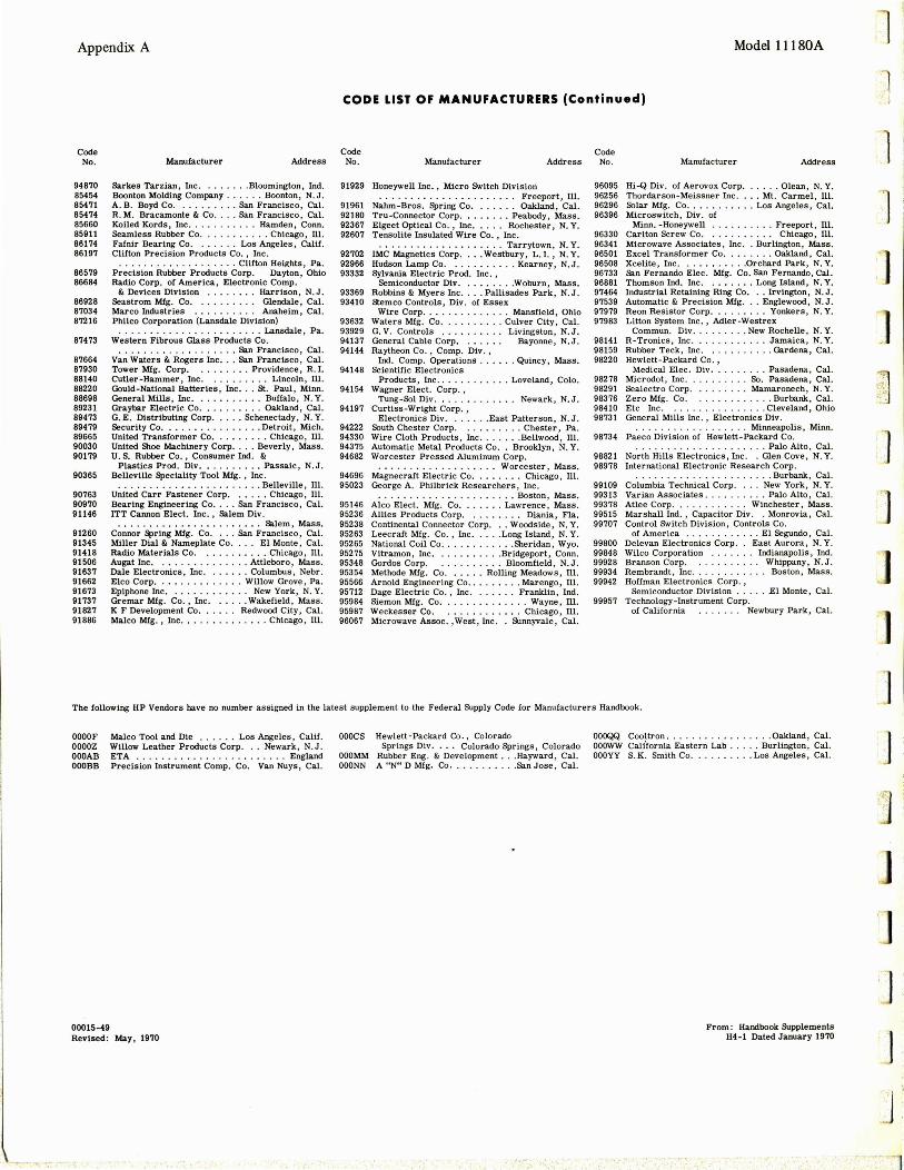
Appendix A Model l ll 80A
CODE LIST OF MANUFACTURERS (Continued)
Code Code Code No. Manufacturer Address No. Manufacturer Address No. Manufacturer Address
94870 85454 85471 85474 85660 85911 86174 86197
86579 86684
86928 87034 87216
87473
87664 87930 88140 88220 88698 89231 89473 89479 89665 90030 90179
90365
90763 90970 91146
91260 91345 91418 91506 91637 91662 91673 91737 91827 91886
Barkes Tarzian, Inc ..... .. . Bloomington, Ind. Boonton Molding Company .... .. Boonton, N. J. A. B. Boyd Co .......... San Francisco, Cal. R. M. Bracamonte & Co .... San Francisco, Cal. Koiled Kords, Inc . . . . . . . .. Hamden, Conn. Seamless Rubber Co. . ... . . . Chicago, Ill. Fafnir Bearing Co. . . . .. . Los Angeles , Calif. Clifton Precision Products Co. , Inc.
. . . . . . . . . . . . . . . . . . . Clifton Heights , Pa. Precision Rubber Products Corp. Dayton, Ohio Radio Corp. of America , Elec tronic Comp.
& Devices Division . . . .. . . . Harrison, N. J . Seastrom Mfg. Co. . . . . . . . . . Glendale, Cal. Marco Industries . . . . . . . . . . Anaheim, Cal. Philco Corporation (Lansdale Division)
. . . . . . . . . . . . . . . . . . . . . . . Lansdale, Pa. Western Fibrous Glass Products Co.
. . . .. . . • . . ......... San Francisco , Cal. Van Waters & Rogers Inc ... San Francisco , Cal. Tower Mfg. Corp. . . . ..... Providence, R. I. Cutler-Hammer, Inc . . ........ Lincoln, Ill. Gould-National Batteries, Inc •.. St. Paul , Minn. General Mills , Inc .. . ......•. Buffalo , N. Y. Graybar Electric Co .......... Oakland, Cal. G. E. Distributing Corp ..... Schenectady, N. Y. Secur ity Co . •... . .......... Detroit, Mich. United Transformer Co. . ....... Chicago , Ill. United Shoe Machinery Corp . . . . Beverly , Mass. U.S. Rubber Co . , Consumer Ind. &
Plastics Prod . Div .......... Passaic, N.J . Belleville Speciality Tool Mfg., Inc .
. . . . . . . . . . . . . . . . . . . . . . . Belleville, Ill . United Carr Fastener Corp. . . ... Chicago, Ill. Bearing Engineering Co .... San Francisco, Cal. ITT Cannon Elect. Inc. , 5alem Div.
. . . . . . . . . . . • . . . . . . . . . . . Salem, Mass. Connor ~ring Mfg. Co .... san Francisco, Cal. Miller Dial & Nameplate Co. . . . El Monte , Cal. Radio Materials Co . . ..... . . . . Chicago, Ill. Augat Inc . . ..... . ... . ... Attleboro , Mass . Dale Electronics , Inc .... ... Columbus , Nebr. Elco Corp ...• .. ... . .... Willow Grove , Pa. Epiphone Inc . ............ New York , N. Y. Gremar Mfg. Co., Inc . . .... Wakefield, Mass. K F Development Co ...... Redwood City, Cal. Malco Mfg. , Inc .............. Chicago, Ill.
91929 Honeywell Inc. , Micro Switch Division . . . . . . . . . . . . . . . . . . . . . . Freepor t, Ill.
91961 Nahm-Bros. Spring Co ....... Oakland, Cal. 92180 Tru-Connector Corp ..... ... Peabody, Mass. 92367 Elgeet Optical Co. , Inc. . . . . Rochester, N. Y. 92607 Tensolite Insulated Wire Co . , Inc.
. . ........ ....... .. . Tarrytown, N. Y. 92702 IMC Magnetics Corp . ... Westbury , L . I., N. Y. 92966 Hudson Lamp Co. . ......... Kearney, N, J . 93332 Sylvania Electric Prod. Inc. ,
Semiconductor Div . ..•. . .. . Woburn, Mass. 93369 Robbins & Myers Inc . ... Pallisades Park, N.J. 93410 stemco Controls, Div. of Essex
Wire Corp. . . . . . . . . . . . . . Mansfield , Ohio 93632 Waters Mfg. Co ......... . Culver City, Cal. 93929 G. V. Controls . . . .. .... . Livingston, N. J. 94137 General Cable Corp. . . . . . . Bayonne, N. J . 94144 Raythe6n Co . , Comp. Div . ,
Ind. Comp. Operations . . . . . . Quincy , Mass. 94148 Scientific Electronics
Products , Inc ............ Loveland, Colo. 94154 Wagner Elect. Corp.,
Tung-Sol Div . . . . . . . Newark , N.J. 94197 Curtiss-Wright Corp. ,
Electronics Div .... .. . East Patterson, N.J. 94222 South Chester Corp. . . . ... .. . Chester , Pa. 94330 Wire Cloth Products, Inc .... . • . Bellwood, Ill . 94375 Automatic Metal Products Co .. Brooklyn , N. Y. 94682 Wor cester Pressed Aluminum Corp.
. ..... . ...... . ... .. Worcester, Mass. 94696 Magnecraft Electric Co .. , . .... Chicago, Ill. 95023 George A. Philbrick Researchers , Inc .
. .. . . ....... .. . ... .. .. Boston, Mass. 95146 Alco Elect. Mfg. Co . .. . , , . Lawrence, Mass. 95236 Allies Products Corp. . ....... Diania , Fla. 95238 Continental Connector Corp ... Woodside, N. Y. 95263 Leecraft Mfg. Co. , Inc ... . . Long Island, N. Y. 95265 National Coil Co ........ . ... Sheridan, Wyo. 95275 Vitramon, Inc . ... .... ... Bridgeport , Conn. 95348 Gordos Corp. . ......... Bloomfield, N. J. 95354 Methode Mfg. Co. . .... Rolling Meadows, Ill. 95566 Arnold Engineering Co . . , .. , . . . Marengo, Ill. 95712 Dage Electric Co., Inc ....... Franklin, Ind. 95984 Siemon Mfg. Co ......... . .... Wayne, Ill. 95987 Weckesser Co. . ....... . .. . Chicago, Ill . 96067 Microwave Assoc. , W~st , Inc .. Sunnyvale, Cal.
96095 Hi-Q Div. of Aerovox Cor p. . . . Olean, N. Y. 96256 Thordarson-Meissner Inc . ... Mt. Carmel, Ill. 96296 Solar Mfg. Co ........... Los Angeles , Cal. 96396 Microswitch, Div. of
Minn. -Honeywell . ........ . Freeport , Ill. 96330 Carlton Screw Co. . . . . . . . . . . Chicago, Ill. 96341 Microwave Associates, Inc .. Burlington, Mass . 96501 Excel Transformer Co ........ Oakland , Cal. 96508 Xcelite, Inc ........... Orchard Park, N. Y . 96733 san Fernando Elec. Mfg. Co. San Fernando, Cal. 96881 Thomson Ind. Inc. . . . .... Long Island, N, Y. 97464 Industrial Retaining Ring Co ... Irvington , N.J. 97539 Automatic & Precision Mfg .. . Englewood , N.J . 97979 Reon Resistor Corp ........ . Yonkers, N. Y. 97983 Litton System Inc . , Adler-Westrex
Commun. Div .. .. . .. . . New Rochelle , N. Y . 98141 R-Tronics, Inc ...... ...... Jamaica, N. Y. 98159 Rubber Teck, Inc. . ......... Gardena, Cal. 98220 Hewlett-Packard Co . ,
Medical Elec. Div . ...... . . Pasadena , Cal. 98278 Microdot , Inc . . .. . ..... So. Pasadena, Cal. 98291 Sealectro Corp ......... Mamaronech , N. Y. 98376 Zero Mfg. Co. . ........... Burbank , Cal. 98410 Etc Inc . . .............. Cleveland, Ohio 98731 General Mills Inc . , Electronics Div .
. . . . . . . . . . . . . . . Minneapolis , Minn. 98734 Paeco Division of Hewlett-Packard Co.
. . . . . . . . . . . . . . . . . . Palo Alto , Cal. 98821 North Hills Electronics , Inc . . Glen Cove, N. Y. 98978 International Electronic Research Corp.
. .............. . Bur bank, Cal. 99109 Columbia Technical Corp. . . . New York, N. Y . 99313 Varian Associates . .. ... .... Palo Alto , Cal. 99378 Atlee Corp. . . . . . . . Winchester, Mass. 99515 Marshall Ind., Capacitor Div. . Monrovia , Cal. 99707 Control Switch Division, Controls Co.
of America . . . . . . El Segundo, Cal. 99800 Delevan Electronics Corp. . East Aurora, N. Y. 99848 Wilco Corporation . . . . . . . Indianapolis, Ind. 99928 Branson Corp. . . Whippany, N. J. 99934 Rembrandt , Inc. . . . . ... Boston, Mass . 99942 Hoffman Electronics Corp. ,
Semiconductor Division . .... .El Monte, Cal. 99957 Technology -Instrument Corp.
of California . Newbury Park, Cal.
The following HP Vendors have no number assigned in the latest supplement to the Federal Supply Code for Manufacturers Handbook.
OOOOF ooooz OOOAB OOOBB
00015-49
Malco Tool and Die .. . . .. Los Angeles , Calif. Willow Leather Products Corp ... Newark , N.J. ETA . . . . . . . . . . . . . . . . . . . . . . . . England Precision Instrument Comp. Co. Van Nuys, Cal.
Revised : May, 1970
OOOCS Hewlett -Packard Co., Colorado Springs Div. . . . Colorado Springs, Colorado
OOOMM Rubber Eng. & Development ... Hayward , Cal. OOONN A "N" D Mfg. Co • .. .. . .. . .. san Jose , Cal.
OOOQQ Cool tr on .... .......... . .. Oakland, Cal. OOOWW Cali'fornia Eastern Lab . .. . . Burlington , Cal. OOOYY S. K. Smith Co ... . ...... Los Angeles, Cal.
From : Handbook Supplements H4-l Dated January 1970
l l ~l
j
]
J
]
J ,,.
J
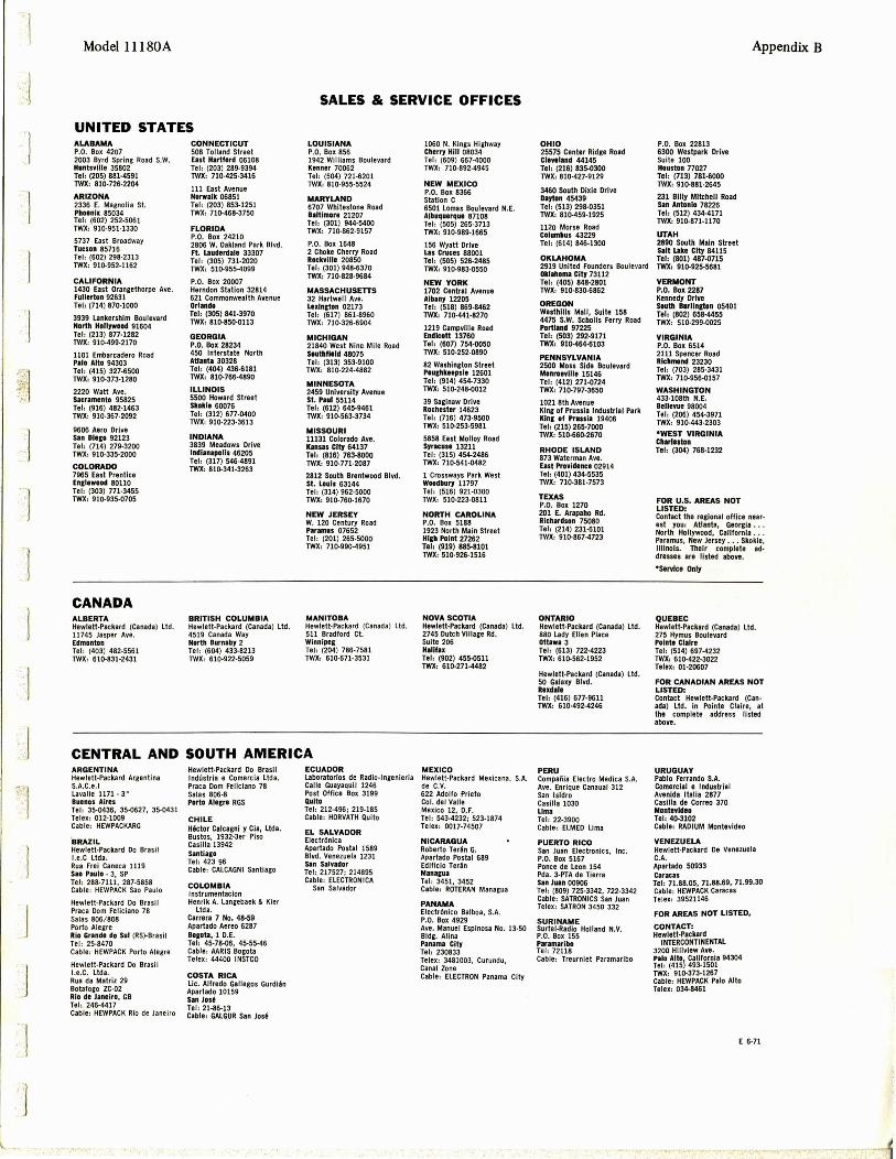
... 1
.l
.]
.j
j
·.j
. ]
Model l l l 80A
UNITED STATES ALABAMA P.O. Box 4207 2003 Byrd Spring Road S.W. Huntsville 35802 Tel , (205) 881-4591 TWJ(, 810·726·2204
ARIZONA 2336 E. Magnolia St. Phoenix 85034 Teh (602) 252·5061 TWX, 910-951-1330
5737 East Broadway Tucson 85716 Teh (602) 298-2313 rwx , 910-952-1162
CALIFORNIA 1430 East Orangethorpe Ave. Fullerton 92631 Teh (714) 870-1000
3939 Lankershlm Boulevard North Hollrwood 91604 Teh (213) 877-1282 rwx , 910.499.2110
1101 Embarcadero Road Palo Alto 94303 Tel , (415) 327-6500 rwx, 910·373-1280
2220 Watt Ave. Sacramento 95825 Tel , (916) 482-1463 TWX, 910·367·2092
9606 Aero Drive san Dltco 92123 Teh (714) 279-3200 rwx, 910.335.2000
COLORAOO 7965 East Prentice En111wood 80110 Teh (303) 771·3455 rwx , 910-935·0705
CANADA ALBERTA Hewlett-Packard (Canada) Ltd. 11745 Jasper Ave. Edmonton Tel , (403 ) 482·5561 TWX , 610·831-2431
CONNECTICUT 508 Tolland Street East Hartford 06108 Tel , (203) 289-9394 TWX, 710·425·3416
111 East Avenue Norwalk 06851 Teh (203) 853-1251 TWX, 710-468-3750
FLORIOA P.O. Box 24210 2806 W. Oakland Park Blvd. Ft. Lauderdale 33307 Teh (305) 731·2020 TWX, 510·955-4099
P.O. Box 20007 Herndon Station 32814 621 Commonwealth Avenue Orlando Tel , (305) 841-3970 TWJ(, 810-850-0113
GEORGIA P.O. Box 28234 450 Interstate North Atlanta 30328 Teh (404) 436-6181 TWJ(, 810-766-4890
ILLINOIS 5500 Howard Street Skokie 60076 Tel, (312) 677-0400 TWX, 910·223-3613
IN DIANA 3839 Meadows Drive lndlanapolls 46205 Teh (317) 546·4891 TWX, 810·341-3263
BRITISH COLUMBIA Hewlett-Packard (Canada) ltd. 4519 Canada Way North Burnaby 2 Teh (604) 433-8213 Twx, 610-922-5059
SALES & SERVICE OFFICES
LOUISIANA P.O. Box 856 1942 Williams Boulevard Kenner 70062 Teh (504) 721-6201 TWX , 810-955·5524
MARYLAND 6707 Whitestone Road Baltimore 21207 Teh (301) 944-5400 TWX , 710·862·9157
P.O. Box 1648 2 Choke Cherry Road RockY111t 20850 Teh (301) 948-6370 TWX, 710-828·9584
MASSACHUSETTS 32 Hartwell Ave . L11lnrton 02173 Teh (617) 861·8960 TWJ(, 710-326-6904
MICHIGAN 21840 West Nine Mile Road Southlltld 48075 Teh (313) 353-9100 Twx, 810-224-4882
MINNESOTA 2459 University Avenue St. Paul 55114 Tel, (612) 645·9461 TWX, 910-563-3734
MISSOURI 11131 Colorado Ave. Kansas City 64137 Tel, (816) 763·8000 TWJ(, 910-771-2087
2812 South Brentwood Blvd. SI. Louis 63144 Tel, (314) 962-5000 TWX, 910·760·1670
NEW JERSEY W. 120 Century Road Paramus 07652 Tel , (201) 265-5000 TWX , 710-990·4951
MANITOBA Hewlett-Packard {Canada) Ltd. 511 Bradford Ct. Winnipeg Ter , (204) 786-7581 TWX, 610·671·3531
1060 N. Kings Highway Cherry H111 08034 Teh (609) 667-4000 TWX , 710-892-4945
NEW MEXICO P.O. Box 8366 Station C 6501 Lomas Boulevard N.E. Albuquerque 87108 Teh (505) 265-3713 TWX, 910-989-1665
156 Wyatt Drive Las Cruces 88001 Teh (505) 526·2485 TWJ(, 910·983-0550
NEW YORK 1702 Central Avenue Albany 12205 Tel, (518) 869·8462 TWJ(, 710·441-8270
1219 Campvllle Road Endicott 13760 Tel, (607) 754-0050 TWX ' 510-252-0890
82 Washlncton Street Pou1hkeepsl1 12601 Tel , (914) 454-7330 TWJ(, 510·248-0012
39 Saginaw Drive Rochester 14623 Teh (716) 473·9500 TWX, 510·253·5981
5858 East Molloy Road Syracuse 13211 Teh (315) 454·2486 TWX, 710-541-0482
1 Crossways Park West Woodbury 11797 Teh (516) 921-0300 TWX , 510-223-0811
NORTH CAROLINA P.O. Box 5188 1923 North Main Street Hl&h Point 27262 Teh (919) 885·8101 TWJ(, 510-926-1516
NOVA SCOTIA Hewlett-Packard (Canada) Ltd. 2745 Dutch Village Rd. Suite 206 Hallfax Tel, (902) 455-0511 TWX, 610·271·4482
CENTRAL AND SOUTH AMERICA ARGENTINA Hewlett·Packard Argentina S.A.C.e./ Lavalle 1171 - 3° Buenos Aires Teh 35·0436, 35·0627, 35·0431 Telex: 012-1009 Cable: HEWPACKARG
'BRAZIL Hewlett-Packard Do Brasil l.e.C Ltda. Rua Frei Caneca 1119 Sao Paulo • 3, SP Tel, 288-7111, 287-5858 Cable: HEWPACK Sao Paulo
Hewlett-Packard Do Brasil Praca Dom Feliciano 78 Salas 806/ 808 Porto Alegre Rio Grande do Sul (RS)-Brasi l Tel: 25-8470 Cable : HEWPACK Porto Alegre
Hewlett.Packard Do Brasi l l .e.C. ltda. Rua da Matriz 29 Botafogo ZC-02 Rio de Janeiro, GB Tel, 246·4417 Cable: HEWPACK Rio de Janeiro
., ......
Hewlett·Packard Do Brasil lndCistria e Comercla Ltda. Praca Dom Felic iano 78 Salas 806·8 Porto Alegre RGS
CHILE H6ctor Calcagni y Cla, Ltda. Bustos, 1932-3er Piso Casilla 13942 Santla10 Te h 423 96 Cable: CALCAGNI Santiago
COLOMBIA lnstrumentacion Henrik A. Langebaek & Kier
Ltd a. Carrera 7 No. 48-59 Apartado Aereo 6287 eoaota, 1 D.E. Tel , 45·78·06, 45·55-46 Cable: AARIS Bogota Telex: 44400 INSTCO
COSTA RICA Lie. Alfredo Gallegos Gurdi.An Apartado 10159 San Jod Tel , 21-86·13 Cable: GALGUR San Jod
ECUAOOR Laboratorlos de Radio·lngenieria Calle Guayaquil 1246 Post Office Box 3199 Quito Teh 212·496; 219-185 Cable, HORVATH Quito
EL SALVADOR Electr6nlca Apartado Postal 1589 Blvd. Venezuela 1231 San Salvador Tel , 217527; 214895 Cable, ELECTRON ICA
San Salvador
MEXICO Hewlett-Packard Mexicana, S.A. de C.V. 622 Adolfo Prieto Col. del Valle Mexico 12, D.F. Tel , 543-4232; 523-1874 Telex, 0017·74507
NICARAGUA Roberto Yer.An G. Apartado Postal 689 Edificlo Yer.An Mana1ua Tel , 3451, 3452 Cable: ROTERAN Managua
PANAMA Electr6nl co Balboa, S.A. P.O. Box 4929 Ave. Manuel Espinosa No. 13-50 Bldg. Alina Panama City Teh 230833 Telex: 3481003, Curundu, Canal Zone Cable: ELECTRON Panama City
OHIO 25575 Center Ridge Road Clevtland 44145 Tel, (216) 835-0300 TWX, 810-427-9129
3460 South Dixie Drive DaJton 45439 Tel, (513) 298-0351 TWX, 810-459-1925
1120 Morse Road Columbus 43229 Tel , (614) 846-1300
OKLAHOMA 2919 United Founders Boulevard Oklahoma City 73112 Tel , (405) 848·2801 TWX , 910-830-6862
OREGON Westh111s Mall, Suite 158 4475 S.W. Scholls Ferry Road Portland 97225 Tel, (503) 292-9171 TWJ(, 910-464-6103
PENNSYLVANIA 2500 Moss Side Boulevard Monroevllle 15146 Teh (412) 271-0724 TWX, 710·797-3650
1021 8th Avenue King of Prussia lndustrlal Park Kine of Prussia 19406 Teh (215) 265·7000 TWX , 510-660-2670
RHODE ISLAND 873 Waterman Ave. East Providence 02914 Tel, (401) 434-5535 TWX, 710·381-7573
TEXAS P.O. Box 1270 201 £. Arapaho Rd. Richardson 75080 Teh (214) 231-6101 TWX, 910·867-4723
ONTARIO Hewlett-Packard (Canada) ltd. 880 Lady Ellen Place Ottawa 3 Teh (613) 722·4223 TWX, 610·562·1952
Hewlett-Packard (Canada) Ltd. so Galaxy Blvd. R11dale Teh (416) 677-9611 TWX, 610-492-4246
PERU Compaf'iia Electro Medica S.A. Ave. Enrique Canaual 312 San Isidro Casilla 1030 Lima Tel , 22-3900 Cable: ELMED Lima
PUERTO RICO San Juan Electronics, Inc. P.O. Box 5167 Ponce de Leon 154 Pda. 3·PTA de Tierra San Juan 00906 Teh (809) 725·3342, 722-3342 Cable: SATRONICS San Juan Telex : SATRON 3450 332
SURINAME Surtel-Radlo Holland N.V. P.O. Box 155 Paramaribo Tel, 72118 Cable : Treurniet Paramaribo
P.O. Box 22813 6300 Westpark Drive Suite 100 Houston 77027 Tel, (713) 781-6000 TWX, 910·881-2645
231 Biiiy Mitchell Road Sin Antonio 78226 Teh (512) 434-4171 TWJ(, 910-871-1170
UTAH 2890 South Main Street Salt Ltke City 84115 Tel, (801) 487-0715 TWJ(, 910-925-5681
VERMONT P.O. Box 2287 Kennedy Drive SOlllll Burllnston 05401 Teh (802) 658-4455 TWX, 510-299-0025
VIRGINIA P.O. Box 6514 2111 Spencer Road Richmond 23230 Tel, (703) 285·3431 TWJ(, 710-956-0157
WASHINGTON 433-108th N.E. Bellevue 98004 Teh (206) 454.3971 TWX , 910·443-2303
•WEST VIRGINIA Charleston Tel, (304) 768-1232
FOR U.S. AREAS NOT LISTED:
Appendix B
Contact the regional office near· est you: Atlanta , Georgia •.• North Hollywood, California •.. Paramus, New Jersey ..• Skokie, Illinois. Their complete addresses are listed above.
•service Only
QUEBEC Hewlett-Packard (Canada) ltd. 275 Hymus Boulevard Pointe Clalre Tel, (514) 697-4232 TWXc 610·422·3022 Telex, Ol-20607
FOR CANADIAN AREAS NOT LISTED: Contact Hewlett-Packard (Canada) Ltd. In Pointe Claire, at the complete address listed above.
URUGUAY Pablo Ferrando S.A. Comerclal e Industrial Avenlda Italia 2877 Casilla de Correo 370 Montevideo Teh 40·3102 Cable: RADIUM Montevideo
VENE2UELA Hewlett-Packard De Venezuela C.A. Apartado 50933 Caracas Tel, 71.88.05 , 71.88.69, 71.99.30 Cable : HEWPACK Caracas Telex: 39521146
FDR AREAS NOT LISTED,
CONTACT: Hewlett~Packard
INTERCONTINENTAL 3200 Hiiiview Ave.
~=:~(~Im ~~~!f S~~a 94304 TWX , 910-373-1267 Cable: HEWPACK Palo Alto Telex: 034-8461
E 6·71

Appendix B
EUROPE AUSTRIA Unllabor GmbH Wissenschaftliche lnstrumente Rummelhardtgasse 6 P.O. Box 33 A-1095 Vienna Teh (222) 42 61 81, 43 13 94 Cable, LABORINSTRUMENT
Vienna Telex: 75 762
BELGIUM Hewlett-Packard S.A. Benelux 348 Boulevard du Souverain 8·1160 Brussels Tel , (02) 722240 Cable: PALOBEN Brussels Telex: 23 494
DENMARK Hewlett-Packard A/S Oatavej 38 OK-3460 Birkerod Te h (01) 81 66 40 Cable: HEWPACK AS Telex: 66 40
Hewlett-Packard A/ S Torvet 9 DK-8600 Silkeb org Ter , (06)-82-71-66
FINLAND Hewlett-Packard Oy Bulevardi 26 P.O. Box 12185 Helsinki 12 Ter, 13-730 Cable, HEWPACKOY-He lslnkl Telex: 12-1563
FRANCE Hewlett-Packard France Quartier de Courtaboeuf Bolte Postale No. 6 F-91 Orsay Ter , 1-920 88 01 Cable: HEWPACK Orsay Telex: 60048
Hewlett-Packa rd France 4 Quai des Etroits F-69 Lyon seme Ter, 78-42 63 45 Cable: HEWPACK Lyon Telex: 31617
Hewlett.Packard France 29 rue de la Gara F·31 Blagnac Te l, (6 1) 85 82 29 Telex: 51957
GERMANY Hewlett·Packard Vertrlebs·GmbH Berliner Strasse 117 Postfach 560/ 40 06 Nieder·Eschbach/ Ffm 56 Tel, (0611) 50 10 64 Cable: HEWPACKSA Frankfurt Telex: 41 32 49 FRA
Hewlett·Packard Vertriebs·GmbH Wflmersdorfer Strasse 113/ 114 D-1000 Berlin W. 12 Tel, (0311) 3137046 Telex: 18 34 05
Hewlett·Packard Vertriebs·GmbH Herrenbergerstrasse 110 07030 BOb lingen, Wi.irttemberg Tel, (07031) 66 72 86 Cable: HEPAG BObllngen Telex: 72 65 739
Hewlett·Packard Vertriebs·GmbH Vogelsanger Weg 38 04 Dilsseldorf Tel, (0211 63 80 31 / 35 Telex, 85/ 86 533
Hewlett-Packard Vertrlebs·GmbH Wendenstr. 23 02 Hamburg 1 Ter , (0411 ) 24 05 51 / 52 Cable: HEWPACKSA Hamburg Te lex: 21 53 32
Hewlett·Packard Vertriebs·GmbH Reginfriedstrasse 13 08 Mi.inchen 9 Tel, (0811) 69 59 71 /75 Cable: HEWPACKSA Milnchen Telex: 52 49 8!:i
GREECE Kostas Karayannis 18, Ermou Street Athens 126 Tel, 230301,3,5 Cab le: RAKAR Athens Tele" 21 59 62 RKAR GR
IRELA NO Hewlett-Pa ckard Ltd. 224 Bath Road Slough, Sll 4 OS, Bucks Tel: Slough 753·33341 Cable: HEWPIE Slough Telex: 84413
ITALY Hewlett-Packard ltaliana S.p.A. Via Amerigo Vespucci 2 1·20124 Milan Ter, (2) 6251 (10 lines) Cable: HEWPACKIT Mi lan Te lex: 32046
Hewlett-Packard ltaliana S.p.A. Palazzo Italia Piazza Marconi 25 1·00144 Rome - Eur Teh 6-591 2544 Cable: HEWPACKIT Rome Telex: 61514
AFRICA, ASIA, AUSTRALIA ANGOLA Telectra Empresa T~c nia
de Equipamentos El~ct ricos SAR
Rua de Barbosa Rodrigues 42·1°
Box 6487 Luanda Cable: TELECTRA Luanda
AUSTRALIA Hewlett-Packard Austra lia
Ply. Ltd. 22·26 Weir Street Glen Iri s, 3146 Victoria Te l : 20.1371 (6 lines) Cable: HEWPARD Melbourne Telex: 31024
Hewlett-Packard Australia Ply. Lid .
61 Alexander Street Crows Nest 2065 New South Wales Ter , 43.7866 Cable: HEWPARD Sydney Telex : 21561
Hewlett-Packard Australia Ply. Lid .
97 Churchill Road Pro spect 5082 South Australia Te r, 65.2366 Cable: HEWPARO Adelaide
Hewlett Packard Australia Ply. Ltd .
2nd Floor, Suite 13 Casab lanca Buildlngs 196 Adelaide Terrace Perth, W.A. 6000 Ter, 21-3330 Cable: HEWPARO Perth
Hewlett-Packard Australia Ply. ltd .
10 Woolley Street P.O. Box 191 Dickson A.C.T. 2602 Tel : 49-8194 Cable: HEWPARD Canberra ACT
Hewlett-Packard Australia Pty. ltd. 75 Simpsons Road Bardon Queensland, 4068 Tel : 36·5411
CEYLON United Electricals ltd . P.O. Box 681 Yahala Building Staples Street Colombo 2 Teh 5496 Cable: HOTPOINT Colombo
CYPRUS Kypronlcs 19 Gregorios & Xenopoulos Road P.O. Box 1152 Nicosia Teh 6282-75628 Cable, HE-1-NAMI
ETHIOPIA African Salespower & Agency
Private Ltd., Co. P. C. Box 718 58/59 Cunningham St. Addis Ababa Tel, 12285 Cable: ASACO Addisababa
Blue Star Ltd. Blue Star House, 34 Ring Road Lajpat Nagar New Deihl 24, India Tel, 62 32 76 Telex: 463 Cable: BLUESTAR
Blue Star ltd. 17·C Ulsoor Road Bangalore-a
Blue Star, Ltd. 96 Park Lane Secunderabad 3, India Tel: 7 63 91 Cable, BlUEFROST
Blue Star, ltd. 23/24 Second li ne Beach Madras 1, India Tel, 2 39 55 Telex: 379 Cab le: BLUESTAR
Blue Star, lid. lB Kaiser Bungalow
HONG KONG Dindfi Road
~~~~~~~ &2~r <Hong Kong) lid. ~!rs~~d ~~r, India
1511, Prince 's Building 15th Floor Cable: BLUESTAR 10, Chaler Road Hong Kong Teh 240168, 232735 Cable: SCHMIOTCO Hong Kong
INOIA Blue Star Ltd. Kasturi Buildings Jamshedji Tata Rd. Bombay 20BR, India Ter, 29 50 21 Telex: 2156 Cable, BlUEFROST
Blue Star Ltd. Band Box House Prabhade11i Bombay 2500, India Tel , 45 73 01 Te lex: 2156 Cable: BLUESTAR
Blue Star Ltd. 14/ 40 Civil Lines Kanpur, India Te l: 6 88 82 Cable : BLUESTAR
Blue Star, Ltd. 7 Hare Street P.O. Box 506 Calcutta 1, Ind ia Tel: 23·0131 Telex: 655 Cable: BLUESTAR
INDONESIA Bah Bolon Trading Coy. N.V. DJalah Merdeka 29 Bandung Teh 4915; 51560 Cable, ILMU Telex: 08-809
IRAN Telecom, ltd. P. o. Box 1812 240 Kh. Saba Shomali Teheran Tel, 43850, 48111 Cable: BASCOM Teheran
IS RAEL Electronics & Engineeri ng
Div. of Motorola Israel Ltd. 17 Amlnadav Street Tel-Aviv Teh 36941 (3 li nes) Cable: BASTEL Tel-Aviv Telex: Baster Tv 033·569
JAPAN Yokogawa-Hewlett·Packard Ltd. Ohashi Building 1·59-1 Yoyogi Shibuya-ku, Tokyo Te l, 03-370-2281 / 7 Telex: 232-2024YHP Cable: YHPMARKET TOK 23·724
NETHERLANDS Hewlett.Packard Bene lux, N.V. Weerdesteln 117 P.O. Box 7825 Am sterdam, Z 11 Ter, 020-42 77 77 Cable: PALOBEN Amsterdam Telex: 13 216
NORWAY Hewlett·Packard Norge A/ S Box 149 Nesveien 13 N-1344 Has lum Tel, (02)-53 83 60 Cable: HEWPACK Os lo Te lex: 16621
PORTUGAL Telectra Empresa Tecni ca de
Equipamentos Electricos, S.a.r.I. Rua Rodr igo da Fonseca 103 P.O. Box 2531 Lisbon 1 Teh 68 60 72 Cable: TELECTRA Lisbon Te lex: 1598
SPAIN Ataio lngenieros SA Enrique Larreta 12 Madrid, 16 Tel , 215 35 43 Cab le: TELEATAIO Madrid Telex: 27249E
Ataio lngenieros SA Ganduxer 76 Barcelona 6 Tel, 211-44-66 Cable: TELEATAIO Barcelona
Yokogawa·Hewlett-Packard ltd. Nisei tbaragi Bldg. 2-2·8 Kasuga lbaragi·Shi Osaka Tel, (0726) 23-1641 Telex: 385·5332 YHPOSAKA
Yokogawa·Hewlett·Packard Ltd. Ito Building No. 59, Kotorl-cho Nakamura-ku, Nagoya City Te r, (052) 551-0215
Yokogawa-Hewlett-Packard lid. Nitto Bldg. 2300 Shinohara-cho, Kohoku-ku Yokohama 222 Teh (405) 432-1504/ 5
KENYA Kenya Kine tics P.O. Box 18311 Nairobi, Kenya Tel , 57726 Cab le: PROTON
KOREA American Trading Co., Korea, Ltd . Seoul P.O. Box 1103 7th & 8th floors, OaeKyung Bldg. 107 Sejong Ro Chongro-Ku, Seoul Tel: 75·5841 (4 lines) Cable: AMTRACO Seoul
LEBANON Constantin E. t4acridls Clemenceau Street P.O. Box 7213 Beirut Tel , 220846 Cable: ELECTRONUCLEAR Beirut
MALAYS IA MECOMB Malaysia ltd. 2 Lorong 13/ 6A Section 13 Petaling Jaya, Selangor Cable: MECOMB Kuala Lumpur
MOZAMBIQUE A. N. Goncalves, LOA. 4.1 Apt. 14 Av. D. Lui s P.O. Box 107 Lourenco Marques Cable: NEGON
NEW ZEALAND Hewlett-Packard (N.Z.) ltd. 94·96 Dixson St. P.O. Box 9443 Wellington, N.Z. Tel , 56-559 Cable: HEWPACK Wellington
Hewlett Packard (N.Z.) ltd. Box 51092 Pukuranga Teh 573-733 Cable: HEWPACK, Auckland
SWEDEN Hewlett-Packard Sverige AB Enighetsvligen 1-3 Fack S-161 20 Bromma 20 Tel , (08) 98 12 50 Cable, MEASUR EMENTS
Stockholm Telex: 10721
Hewlett-Packard Sverige AB Hagakersgatan 9C S·431 41 MOlndal Tel , 031 - 27 68 00 Telex: 21 312 hpmlndl
SWITZERLAND Hewlett Packard Schweiz AG Zurcherstrasse 20 CH-8952 Schlieren Zurich Te l, (051) 98 18 21 /24 Cable: HPAG CH Telex: 53933
Hewlett Packard Schweiz A.G. Rue du Bois·du·Lan 7 1217 Meyrin 2 Geneva Teh (022) 41 54 00 Cable: HEWPACKSA Geneva Telex: 27333 HPSA CH
TURKEY Te lekom Engineering Bureau P.O. Box 376 Karakoy Istanbul Teh 49 40 40 Cab le: TELEMATI ON Istanbul
PAKISTAN (EASn Mushko & Company, ltd. 1, Jinnah Avenue Dacca 2 Teh 280058 Cable: NEWDEAL Dacca
PAKISTAN (WEST) Mushko & Company, Ltd. Cosman Chambers Abdullah Haroon Road Karachi 3 Tel, 511027, 512927 Cable: COOPERATOR Karachi
PHILIPPINES Electromex Inc. Makatl Commercial Center 2129 Pasong Tamo Makati, Rizal D 708 P.O. Box 1028 Manila Teh 89-85-01; 88-91-71 Cable: ELEMEX Manila
SINGAPORE Mechanical and Combustion
Engineering Company ltd. 9, Jalan Kilang Red Hill Industrial Estate Singapore, 3 Tel, 642361-3; 632611 Cable: MECOMB Singapore
Hewlett·Packard Far East Area Offi ce P.O. Box 87 Alexandra Post Offi ce Singapore 3 Teh 633022 Cab le, HEWPACK SINGAPORE
SOUTH AFRICA Hewlett Packard South Africa
(Pty. ), ltd. P.O. Box 31716 Braamfontein Transvaal Milnerton 30 De Beer Street Johannesburg Tel, 725-2080, 725-2030 Telex, 0226 JH Cable: HEWPACK Johannesburg
Hewlett Packard South Africa (Pty.), l td .
Breecastte House Bree Street Cape Town Tel, 3-6019, 3-6545 Cable: HEWPACK Cape Town Telex: 5·0006
Hewlett Packard South Af rica (Ply .), Ltd.
30B Glenwood Centre Corner Hunt & Moore Roads P.O. Box 99 Overport, Natal Tel: 347536
Model l l 180A
UN ITED KINGDOM Hewlett-Packard Ltd . 224 Bath Road Slough, Sll 4 OS, Bucks Teh Slough (0753 ) 33341 Cable: HEWPIE Slough Telex: 84413
Hewle tt·Packard Ltd. The Graftons Stamford New Road Altrincham, Cheshire Te l, 061 928-8626 Telex: 668068
YUGOSLAVIA Belram S.A. 83 avenue des Mimosas Brussels 1150, Be lgium Teh 34 33 32, 34 26 19 Cable: BELRAMEL Brussels Tele x: 21790
SOCIALIST COUNTRIES PLEASE CONTACT: Hewlett-Packard Ges.m.b.H lnnstrasse 23/2 Postfach Al204 Vienna, Austria Te r, (222) 3366 06/ 09 Cable: HEWPACK Vienna Telex: 75923
ALL OTHER EUROPEAN COUNTRIES CONTACT: Hewlett-Packard S.A. Rue du Bois·dU·Lan 7 1217 Meyrin 2 Geneva
Switzerland Teh (022) 41 54 00 Cable: HEWPACKSA Geneva Telex: 2.24.86
TAIWAN Hewlett Packard Taiwan 39 Chung Shiao West Road Sec. 1 Overseas Insurance Corp. Bldg. 7th Floor Taipei Teh 579-605, 579-610, 579-613 Telex: TP824 HEWPACK Cable: HEWPACK Taipei
THAI LAND The International
Engineering Co., Ltd. P. o. Box 39 614 Sukhumvlt Road Bangkok Teh 910722 (7 lines) Cable: GYSOM TLX INTENCO BK-226 Bangkok
UGANDA Uganda Tete-Electri c Co ., Ltd . P.O. Box 4449 Kampala Tel, 57279 Cable: COMCO Kampala
VIETNAM Peninsular Tra ding Inc. P.O. Box H-3 216 Hien-Vuong Salcon Tel, 20805, 93398 Cab le, PENTRA, SAIGON 242
ZAMBIA R. J. Tilbury (Zambia) Ltd. P.O. Box 2792 Lusaka Zambia, Central Africa Ter, 73793 Cable: ARJAYTEE, Lusaka
MEDITERRANEAN ANO MIDDLE EAST COUNTRIES NOT SHOWN PLEASE CONTACT: Hewlett-Packard Correspondence Office Piazza Marconi 25 1·00144 Rome-Eur, Italy Tel , (6) 59 40 29 Cable: HEWPACKIT Rome Telex : 61514
OTHER AREAS NOT LISTED, CONTACT: Hewlett-Packard
INTERCONTI NENTAL 3200 Hillview Ave. Palo Alto, California 94304 Teh (415) 326-7000
(Fe b. 71 493-1501) Twx, 910-373-1267 Cable: HEWPACK Palo Alto Telex: 034·8461
E 6-71
-1