How2Power's Power Supply EMI Anthology
22
How2Power’s Power Supply EMI Anthology 1 A select list of design-oriented articles and videos discussing electromagnetic interference (EMI) and electromagnetic compliance (EMC) issues as related to power supply design. These articles and videos were published in the How2Power Today newsletter. This list includes abstracts and links for these materials plus information on where to find more EMI and EMC-related articles, books, and other resources. Contents 1. Measuring And Troubleshooting EMI ............................................................................................ 3 Troubleshooting EMI: Use Versatile Instrument And Preamp To Search For Embedded Noise .................. 3 Video Troubleshooting Distributed Power Systems (Part 6): The Switch .................................................... 4 The Most Important Concept In EMI Diagnosis .......................................................................................... 4 Understanding LISNs Is Essential To EMI Pre-Compliance Testing .............................................................. 4 A Power Supply Can’t Fix All EMC Woes, Yet Partnering With The Right Power Supply Experts Early Can . 4 The Engineer’s Guide To EMI In DC-DC Converters (Part 1): Standards Requirements And Measurement Techniques.................................................................................................................................................. 5 The Engineer’s Guide To EMI In DC-DC Converters (Part 4): Radiated Emissions ....................................... 5 Strategies For Pre-compliance EMI Testing Of Radiated Emissions ............................................................ 5 Measuring Common-Mode And Differential-Mode EMI Currents .............................................................. 6 Advanced Scopes And Probes Help Optimize SMPS Gate Drives For EMC .................................................. 6 2. Reducing Power Supply EMI By Design.................................................................................................. 6 How To Control Phase Voltage Ringing In Synchronous Buck Converters .................................................. 6 Livin’ On The Edge: Switching Converter Slew Rate Is Key To Mitigating EMI In Automotive Environments .................................................................................................................................................................... 7 3D FEA Software Solves Tough Inductive Noise Problems .......................................................................... 7 Common-Mode Transformer Aids Noise Reduction In High-Power Supplies ............................................. 7 Take The Edge Off High dV/dt Supplies ...................................................................................................... 8 Leakage Inductance (Part 2): Overcoming Power Losses And EMI ............................................................. 8 Reducing Noise Generated By Switching Regulators .................................................................................. 8 Multi-Output Fly-Buck Regulator Offers Wide V IN , Isolation And Low EMI ................................................. 8 EMI For Wisdom Seekers: (Part 1): What New EEs And MEs Need To Know .............................................. 9 EMI For Wisdom Seekers (Part 2): Keeping It Simple .................................................................................. 9 EMI For Wisdom Seekers (Part 3): Differential Mode Noise Versus Common Mode Noise ........................ 9
-
Upload
khangminh22 -
Category
Documents
-
view
1 -
download
0
Transcript of How2Power's Power Supply EMI Anthology
How2Power’s Power Supply EMI Anthology
1
A select list of design-oriented articles and videos discussing electromagnetic interference (EMI) and
electromagnetic compliance (EMC) issues as related to power supply design. These articles and videos
were published in the How2Power Today newsletter. This list includes abstracts and links for these
materials plus information on where to find more EMI and EMC-related articles, books, and other
resources.
Contents 1. Measuring And Troubleshooting EMI ............................................................................................ 3
Troubleshooting EMI: Use Versatile Instrument And Preamp To Search For Embedded Noise .................. 3
Video Troubleshooting Distributed Power Systems (Part 6): The Switch .................................................... 4
The Most Important Concept In EMI Diagnosis .......................................................................................... 4
Understanding LISNs Is Essential To EMI Pre-Compliance Testing .............................................................. 4
A Power Supply Can’t Fix All EMC Woes, Yet Partnering With The Right Power Supply Experts Early Can . 4
The Engineer’s Guide To EMI In DC-DC Converters (Part 1): Standards Requirements And Measurement
Techniques .................................................................................................................................................. 5
The Engineer’s Guide To EMI In DC-DC Converters (Part 4): Radiated Emissions ....................................... 5
Strategies For Pre-compliance EMI Testing Of Radiated Emissions ............................................................ 5
Measuring Common-Mode And Differential-Mode EMI Currents .............................................................. 6
Advanced Scopes And Probes Help Optimize SMPS Gate Drives For EMC .................................................. 6
2. Reducing Power Supply EMI By Design .................................................................................................. 6
How To Control Phase Voltage Ringing In Synchronous Buck Converters .................................................. 6
Livin’ On The Edge: Switching Converter Slew Rate Is Key To Mitigating EMI In Automotive Environments
.................................................................................................................................................................... 7
3D FEA Software Solves Tough Inductive Noise Problems .......................................................................... 7
Common-Mode Transformer Aids Noise Reduction In High-Power Supplies ............................................. 7
Take The Edge Off High dV/dt Supplies ...................................................................................................... 8
Leakage Inductance (Part 2): Overcoming Power Losses And EMI ............................................................. 8
Reducing Noise Generated By Switching Regulators .................................................................................. 8
Multi-Output Fly-Buck Regulator Offers Wide VIN, Isolation And Low EMI ................................................. 8
EMI For Wisdom Seekers: (Part 1): What New EEs And MEs Need To Know .............................................. 9
EMI For Wisdom Seekers (Part 2): Keeping It Simple .................................................................................. 9
EMI For Wisdom Seekers (Part 3): Differential Mode Noise Versus Common Mode Noise ........................ 9
How2Power’s Power Supply EMI Anthology
2
EMI For Wisdom Seekers (Part 4): Minimizing Parasitic Current Loops ...................................................... 9
The Engineer’s Guide To EMI In DC-DC Converters (Part 2): Noise Propagation And Filtering ................. 10
The Engineer’s Guide To EMI In DC-DC Converters (Part 3): Understanding Power Stage Parasitics........ 10
PCB Board Layout Is Critical When The Power Supply And MCU Live On The Same Board ...................... 10
Switching Power Supplies And EMI: Debunking The Myths About Frequency And Slew Rate .................. 11
The Engineer’s Guide To EMI In DC-DC Converters (Part 5): Mitigation Techniques Using Integrated FET
Designs...................................................................................................................................................... 11
The Engineer’s Guide To EMI In DC-DC Converters (Part 6): Mitigation Techniques Using Discrete FET
Designs...................................................................................................................................................... 11
The Engineer’s Guide To EMI In DC-DC Converters (Part 7): Common-Mode Noise Of A Flyback ............ 11
The Engineer’s Guide To EMI In DC-DC Converters (Part 8): Common-Mode Noise Mitigation In Isolated
Designs...................................................................................................................................................... 12
Field Solvers: A Different Perspective On EMI In Power Electronics ......................................................... 12
The Engineer’s Guide To EMI In DC-DC Converters (Part 13): Predicting the Common-Mode Conducted
Noise Spectrum......................................................................................................................................... 12
The Engineer’s Guide To EMI In DC-DC Converters (Part 14): Behavioral Noise Modeling ....................... 13
3. Filtering And Suppressing EMI ..................................................................................................... 13
Frequency Dithering: A Tool For Overcoming Last-Minute EMC Hurdles ................................................. 13
Beyond Power Management: Power Engineers Must Also Solve ESD, EMI, And RFI Problems ................ 13
A Guide To The Operation And Use Of Input EMI Filters For Switching Power Supplies ........................... 14
Using Ruggedized EMI Filters To Pass The CS101 Requirement Of MIL-STD-461D-F ................................ 14
Free Tool Takes The Drudgery Out Of Designing EMI Filters..................................................................... 14
Leakage Inductance (Part 3): Improving Power Supply Filtering, Efficiency And Density ......................... 14
Random PWM Quiets Noise And Reduces Emissions In Three-Phase Inverter Applications .................... 15
Proper Design of the Power Supply’s Input EMI Filter Protects Against Power Line Transients ............... 15
A Methodical Approach To Snubber Design ............................................................................................. 15
The Engineer’s Guide To EMI In DC-DC Converters (Part 9): Spread-Spectrum Modulation ..................... 16
Selecting An AC Line Filter For Switching Power Supply Applications ....................................................... 16
The Engineer’s Guide To EMI In DC-DC Converters (Part 10): Input Filter Impact on Stability.................. 16
The Engineer’s Guide To EMI In DC-DC Converters (Part 11): Input Filter Impact On Dynamic
Performance ............................................................................................................................................. 17

How2Power’s Power Supply EMI Anthology
3
The Engineer’s Guide To EMI In DC-DC Converters (Part 12): Predicting The Differential-Mode Conducted
Noise Spectrum......................................................................................................................................... 17
The Engineer’s Guide To EMI In DC-DC Converters (Part 15): Differential-Mode Input Filter Design ....... 17
EMC+SIPI Talks Reveal More About EMI Filter Design For Flyback Converters ......................................... 17
The Engineer’s Guide To EMI In DC-DC Converters (Part 16): Common-Mode Input Filter Design........... 18
The Engineer’s Guide To EMI In DC-DC Converters (Part 17): Active And Hybrid Filter Circuits ............... 18
The Engineer’s Guide To EMI In DC-DC Converters (Part 18): Advanced Spread-Spectrum Techniques... 18
4. More EMI/EMC articles And Resources ....................................................................................... 19
Highly Practical EMC Book Will Pay For Itself ............................................................................................ 19
EMC Wisdom Has A Long Shelf Life........................................................................................................... 20
All-In-One Test Solution Accelerates EMI/EMC Pre-Compliance Testing .................................................. 20
Power Magnetics Roundup: EMI Filters .................................................................................................... 20
An Introduction To Medical Regulations: Understanding The 60601 Standard ........................................ 20
Explaining The ROI Of Compliance Efforts To Your Colleagues ................................................................. 20
EMC+SIPI Symposium Offered Practical Instruction, Latest Equipment And R&D .................................... 21
Power Supply Book Also Explains EMI And EMC Requirements................................................................ 21
EMC+SIPI Symposium Shares Valuable Tutorials Virtually ........................................................................ 21
WBG Semiconductors Pose Safety And EMI Challenges In Motor Drive Applications .............................. 22
One Month Left To Download EMC + SIPI 2021 Proceedings ................................................................... 22
1. Measuring And Troubleshooting EMI Troubleshooting EMI: Use Versatile Instrument And Preamp To Search For Embedded Noise
by Steve Sandler, Picotest, Phoenix, Ariz.
Abstract: Most engineers do not have convenient access to the equipment necessary for
electromagnetic compliance (EMC) or electromagnetic interference (EMI) testing. Certified test labs,
while readily available, and necessary for conformance testing, are a very expensive solution for troubleshooting EMI/EMC issues that ought to be addressed during product development. In this
video, Steve Sandler demonstrates a test-setup that may be used to troubleshoot EMI during product
design and development using readily accessible test equipment. While these same tests may be performed with various test instruments, two of the instruments selected for use in this demo—the
LeCroy Waverunner 610Zi oscilloscope with built-in spectrum analyzer and the Picotest J2180A
preamp—offer a mix of performance, versatility, and cost that justifies their use in these measurements.

How2Power’s Power Supply EMI Anthology
4
Notes: 2 minutes. View the Video…
Video Troubleshooting Distributed Power Systems (Part 6): The Switch
by Steve Sandler, AEi Systems and Picotest, Phoenix, Ariz.
Abstract: System and power converter issues are frequently related to a converter’s switching
characteristics, which are most easily observed at the switching node. In this video, Steve Sandler
discusses the measurement and interpretation of switch-node waveforms as observed in point-of-load regulators (POLs). He discusses the instrumentation requirements for measuring switch-node
waveforms, why these waveforms should be viewed using different time scales, and the impact of
scope probes on these measurements. With those measurement requirements as background, Sandler examines how switching frequency and duty cycle affect power supply stability as well as EMI.
Notes: 9-min. 36-sec. runtime. Watch the video…
The Most Important Concept In EMI Diagnosis
by Franki N.K. Poon, PowerELab, Shatin, N.T., Hong Kong
Abstract: After all the work that has been done to analyze and treat EMI in power supplies, it is about
time we stop describing the analysis and treatment of EMI as a “black art.” Clearly, EMI topics have been studied to the point where the underlying issues are understood, techniques for dealing with EMI
are well established, and this knowledge is readily available to the engineering community.
Nevertheless, EMI engineers still feel frustrated at times with theories and real world measurements. One of the sources of this frustration is the conflict between the log scaling required to measure and
assess EMI and the engineer’s “linear” mindset. It is important for engineers to adapt to log scales in
order to apply EMI theories on diagnostic techniques effectively, gain valuable experience in these areas, and to obtain more consistent results. This article discusses some common mistakes that
engineers make in interpreting log-scale EMI measurements, explains why different engineers
performing similar tests draw different conclusions about the causes of EMI, why the search for a “dominant” noise source is counterproductive, and describes a more effective approach to addressing
EMI issues in power supply designs.
Notes: 8 pages, 10 figures. Read the full story…
Understanding LISNs Is Essential To EMI Pre-Compliance Testing
by Kevin Parmenter, Chair, and James Spangler, Co-chair, PSMA Safety and Compliance Committee
Abstract: A line impedance stabilization network (LISN) is a circuit used for testing power supply line conducted emissions produced by either a power supply or some other type of product that contains a
power supply. The network is inserted into the power supply lines to determine if the product is
emitting unwanted high frequencies that will interfere with other products plugged into the same outlet or power source. Since there are multiple standards that require conducted emissions testing, if
you are designing power supplies, chances are you’ll need to meet some of these requirements and
you’ll need to know enough about LISNs to perform pre-compliance testing of your product. The same may be true even if you’re applying someone else’s power supplies in your system designs. In this
column, the authors explain the basics of how LISNs work and are used, identify some of the
applicable standards, and then analyze the differences between the LISNs specified by two FCC
standards to help engineers understand when these differences affect testing and when they don’t.
Notes: 4 pages, 5 figures. Read the full story…
A Power Supply Can’t Fix All EMC Woes, Yet Partnering With The Right Power Supply
Experts Early Can

How2Power’s Power Supply EMI Anthology
5
by Kevin Parmenter, Chair, and James Spangler, Co-chair, PSMA Safety and Compliance Committee
Abstract: Recently I was called by a customer who was failing EMC in the test lab. They were using
one of our competitor’s power supplies and we had been talking with them about using ours because
of its superior value and performance. It was hard to ascertain if our pitch was falling on deaf ears or not. But now, with their product failing compliance testing, suddenly we were important to them as
evidenced by them calling me after hours. The discussion went something like “does your power
supply have lower EMC than the one I’m now using?” Of course they were talking about radiated EMC as I already had helped them with selecting a line filter, which was sufficient to make sure either
power supply would pass conducted EMC. With their product in the test lab there was real urgency as
the money meter was running with the test lab charging them by the hour as the customer tried to get their product to pass EMC. This is their story and the lessons learned.
Notes: 3 pages, 2 figures. Read the full story…
The Engineer’s Guide To EMI In DC-DC Converters (Part 1): Standards Requirements And
Measurement Techniques
by Timothy Hegarty, Texas Instruments, Phoenix, Ariz.
Abstract: Although the emergence of faster-switching power devices for dc-dc converters provides an opportunity for increased switching frequency and smaller size, the higher switch voltage and current
slew rates that occur during switching transitions often exacerbate EMI, causing problems in the
overall system. For example, the high-switching speed of GaN power devices can raise EMI by 10 dB at high frequencies. EMI filters are inevitably part of a power electronic system, but since filtering
adds unwanted size and cost, it’s incumbent on the power designer to focus on system EMI noise
reduction and mitigation. This article, the first in a multipart series on EMI, reviews relevant standards for both industrial and automotive end equipment. This part also explains the associated measurement
techniques with an eye toward pre-compliance testing. The focus here and throughout the series is
mainly on conducted emissions.
Notes: 8 pages, 7 figures, 1 table. Read the full story…
The Engineer’s Guide To EMI In DC-DC Converters (Part 4): Radiated Emissions
by Timothy Hegarty, Texas Instruments, Phoenix, Ariz.
Abstract: Part 4 of this article series offers some perspective on radiated emissions from switching
power converters, particularly those intended for applications in the industrial and automotive sectors.
Radiated electromagnetic interference (EMI) is a dynamic and situational problem that depends on parasitic effects, circuit layout and component placement within the power converter itself as well as
the overall system in which it operates. Thus, the issue of radiated EMI is typically more challenging
and complex from the design engineer’s perspective, particularly when multiple dc-dc power stages are located on the system board. It’s important to understand the basic mechanisms for radiated EMI,
as well as the measurement requirements, frequency ranges and applicable limits. This article focuses
on these aspects and presents radiated EMI measurement setups and results for two dc-dc buck converters.
Notes: 14 pages, 16 figures, 6 tables. Read the full story…
Strategies For Pre-compliance EMI Testing Of Radiated Emissions
by Dylan Stinson, Tektronix, Portland, Oreg.
Abstract: Radiated emissions testing is done to ensure that any electromagnetic radiation from a
How2Power’s Power Supply EMI Anthology
6
product during normal operation falls below limits defined for that type of product. You can often avoid
multiple unwanted trips to the test house and ill-timed product delays by measuring the electrical noise emitted from your product prior to going to the test house. Not only will this type of pre-
compliance testing—which is easier and more affordable than you might think—increase your chances
of passing EMC compliance testing the first time out, it can help you identify potential issues early on
and reduce the need for last-minute product redesigns. This article discusses the types of equipment required for performing precompliance radiated EMI testing, and offers guidelines for making the test
setups and measurements.
Notes: 5 pages, 4 figures. Read the full story…
Measuring Common-Mode And Differential-Mode EMI Currents
by Kevin Parmenter, Chair, and James Spangler, Co-chair, PSMA Safety and Compliance Committee
Abstract: Line-conducted EMI current is composed of two elements: common mode (CM) current and
differential mode (DM) current. Either one of these contributors to line-conducted EMI may be responsible for a unit failing EMC testing. And without knowing why a unit is failing, coming up with a
solution can become a time-confusing exercise in trial and error. On the other hand, by measuring CM
and DM EMI currents separately, engineers can identify why their products are exceeding the specified EMI limits and quickly tailor an EMI filter solution to pass EMC testing. Although the techniques for
measuring CM and DM currents are well documented in the literature, many power supply engineers
are still unfamiliar with them and therefore do not make these measurements. In this article, the
authors review the literature regarding measurement of CM and DM EMI currents, offer an overview of the different measurement techniques and point to the references where readers can delve more into
the details of making the measurements.
Notes: 6 pages, 5 figures, 1 table. Read the full story…
Advanced Scopes And Probes Help Optimize SMPS Gate Drives For EMC by Michael Fuchs, Bernhard Auinger and Lukas Pichler, Institute of Electronics (IFE) at the Graz
University of Technology, Styria, Austria; Markus Herdin, Rohde & Schwarz, Munich, Germany; and
Bernd Deutschmann, Institute of Electronics (IFE) at the Graz University of Technology, Styria, Austria
Abstract: The introduction of wide-bandgap semiconductor materials such as SiC and GaN has
enabled higher switching frequencies as well as much steeper edges on switching waveforms. This increases the efficiency of switched-mode power supply units, but results in unwanted, high-frequency
interference that propagates along connecting cables or is emitted as electromagnetic waves. The
Institute of Electronics (IFE) at the Graz University of Technology in Austria is conducting electromagnetic compatibility (EMC) research on gate drive methods with a view to minimizing
spurious emissions. High-performance oscilloscopes such as the R&S RTO2000 enable these
optimization measures to be implemented on the developer's lab bench. This article describes the measurements necessary for gate drive optimization and offers some measurement examples to
illustrate the setups and measurement results that can be obtained.
Notes: 7 pages, 6 figures. Read the full story…
2. Reducing Power Supply EMI By Design
How To Control Phase Voltage Ringing In Synchronous Buck Converters
by Suresh Kariyadan, International Rectifier, El Segundo, Calif.
How2Power’s Power Supply EMI Anthology
7
Abstract: In synchronous buck converters, fast switching of the MOSFETs can cause high-voltage spikes and ringing at the phase node. These effects are undesirable because they can cause increased
power dissipation, higher voltage stress on the switching devices, higher EMI, and higher peak-to-
peak output ripple and noise at higher bandwidth. In this article, an integrated buck converter is used
to study the undesired voltage spikes and ringing at the phase node caused by fast switching. The focus here is mainly on the peak-to-peak output ripple voltage that occurs at higher bandwidth.
Experiments are conducted to gauge the impact of different methods used to control this ringing, and
the pros and cons of these methods are discussed.
Notes: 11 pages, 7 figures. Read the full story…
Livin’ On The Edge: Switching Converter Slew Rate Is Key To Mitigating EMI In Automotive
Environments
by Matt Jenks and Paul L. Schimel, International Rectifier, El Segundo, Calif.
Abstract: The state-of-the-art automobile can be viewed as a common chassis that attempts to enclose the RF soup that is radiated and conducted by an increasing plethora of onboard electronics.
This spectral soup sees noise contributions from dc-dc converters running processors and computers,
inverters running traction motors, choppers running pumps and many assorted motors, class D audio
amplifiers, and switching converters for LED lighting and brush motor commutation to name a few. The primary focus of this piece is on the brushed dc motors and the choppers or drivers that run
them. This article will discuss the noise output of these circuits, the applicable EMI standards and the
points of sensitivity that drove those standards. The focus here will be on the edges of the switching converter waveforms and their impact on radiated noise.
Notes: 5 pages, 1 figure, 2 tables. Read the full story…
3D FEA Software Solves Tough Inductive Noise Problems
by Peter Markowski, Envelope Power, Ansonia, Conn.
Abstract: Switched-mode power supplies are notorious for hard-to-eliminate noise problems simply
because we cannot completely avoid proximity of high-power switching circuits and sensitive controls. Good engineering practices such as minimizing high-frequency current loops and voltage surfaces,
perpendicular arrangement of potential source-target sets and using large copper planes for shielding
are naturally a must. But without any way of quantifying problematic phenomena it is impossible to know if we are pushing our luck and if we did the best we could within the given constraints. However,
as the author explains here, dangerous noise can be reduced and many layout re-spins avoided if we
model potential trouble spots with the latest-generation 3D FEA software, which has the necessary modeling power and user friendliness to be applied in power supply design.
Notes: 10 pages, 11 figures. Read the full story…
Common-Mode Transformer Aids Noise Reduction In High-Power Supplies
by Dennis Feucht, Innovatia Laboratories, Cayo, Belize
Abstract: In a typical switched-mode power supply transformer, the capacitance between primary
and secondary windings is distributed along the windings. This interwinding capacitance can be represented by an equivalent capacitor, Cseq, across the middle of the primary and secondary
windings. This interwinding capacitance offers a path for parasitic currents, which result from voltage
differences across the primary and secondary windings. Those parasitic currents, in turn, can become a source of noise, which is particularly troublesome in power supplies with higher power output.
However, these parasitic currents can be avoided with the addition of a common-mode transformer as
explained in this article.

How2Power’s Power Supply EMI Anthology
8
Notes: 3 pages, 1 figure. Read the full story…
Take The Edge Off High dV/dt Supplies
by Rob McCarthy, Maxim Integrated, San Jose, Calif.
Abstract: High dV/dt rise times on the power supply can cause problems with downstream
components. This is especially true in 24-V powered industrial and automotive systems with high-current output drivers. This design idea describes how to control the rise time while limiting the power
loss through the control FET. Rather than using a p-channel MOSFET as the current-limiting element,
this circuit employs an n-channel MOSFET, which offers lower on-resistance and therefore limits power dissipation better. This capability makes the circuit well suited for applications where supply current is
8 A or higher. The circuit is built around the MAX16127 controller, which was developed to provide
overvoltage protection but serves well in this role in controlling power supply rise time.
Notes: 3 pages, 3 figures. Read the full story…
Leakage Inductance (Part 2): Overcoming Power Losses And EMI
by Ernie Wittenbreder, Technical Witts, Flagstaff, Ariz.
Abstract: Leakage inductance is our foe when it creates problems such as power losses, EMI, or
degraded regulation. In most isolated converters, leakage inductance contributes to both power losses
and EMI, but there are ways in which power losses and EMI can be avoided by design. The first course of action is to design the transformer for low leakage inductance, but sometimes that approach is too
costly or requires more space than is available, so other methods are needed. In this part 2, the
various clamp and snubber options are discussed including RCD clamp, RC snubber, LCD clamp and active clamps. The pros and cons and varying requirements of the different approaches are discussed
mainly within the context of the flyback topology, but also touching on the LCD clamp in the single-
ended forward converter, and active clamps in the coupled-boost converter. Finally, this part looks at techniques for improving load regulation degraded by leakage inductance.
Notes: 17 pages, 9 figures. Read the full story…
Reducing Noise Generated By Switching Regulators
by Frederik Dostal, Analog Devices, Munich, Germany
Abstract: Switched-mode power supplies generate noise. In many applications this noise needs to be
limited so that analog data integrity is not compromised and also to pass certain EMI requirements. This article will introduce different types of noise we find in switched-mode power supplies (SMPSs),
discuss different noise-coupling mechanisms and ultimately present solutions to reduce the generation
of noise and to filter remaining disturbances with the best strategies. While the concepts discussed here are generally applicable to all SMPS designs, the focus here is mainly on the type of nonisolated,
dc-dc converters or point-of-load converters (POLs) that are used to generate the various low-voltage
supply rails in electronic systems.
Notes: 7 pages, 8 figures. Read the full story…
Multi-Output Fly-Buck Regulator Offers Wide VIN, Isolation And Low EMI
by Timothy Hegarty, Texas Instruments, Phoenix, Ariz.
Abstract: The power management requirements in industrial, medical, automotive and transportation
end markets are setting new challenges for design engineers. System performance requirements for
the power converters dictate high density and high switching frequency coupled with increasing
How2Power’s Power Supply EMI Anthology
9
emphasis on a wide input voltage range, multiple output rails, galvanic isolation, and compliance with
EMI regulations and, in many cases, stringent transient and safety standards. The Fly-Buck converter has gained prominence as a solution to provide low-current auxiliary and bias outputs from a widely-
ranging input supply up to 100 V, especially if both isolated and non-isolated rails are required. In
comparison with conventional flyback or push-pull topologies, the Fly-Buck offers simplicity,
versatility, small size, high reliability, and low BOM cost. This article discusses the advantages of the Fly-Buck in the context of a multi-output Fly-Buck design example
Notes: 6 pages, 4 figures, 1 table. Read the full story…
EMI For Wisdom Seekers: (Part 1): What New EEs And MEs Need To Know
by Patrice Lethellier, Noizgon, Salt Lake City, Utah
Abstract: Much has already been written on the subject of EMI/EMC. Is another primer on the subject
really needed? Yes! First of all, new EEs are always coming into the field for whom EMI/EMC is a new
subject. But there are also many non-EEs who need basic knowledge of this subject, in particular the mechanical engineers (MEs) who design the packaging for power converters, supplies or systems. The
impact of their work on EMI performance becomes especially significant at higher power levels. Yet so
often these MEs do not receive adequate guidance from the EEs and the packaging design wreaks havoc on the system’s EMI performance. So this EMI primer is written with both the novice EEs and
the MEs in mind. It is hoped that experienced power electronics designers, who already know the
subject well, will also read this material and use it as a tool for educating their mechanical engineering colleagues. To explain why packaging design is so critical to EMI performance in high-power
applications, this article discusses how designing high-power power electronics differs from designing
low-power power electronics.
Notes: 4 pages. Read the full story…
EMI For Wisdom Seekers (Part 2): Keeping It Simple
by Patrice Lethellier, Noizgon, Salt Lake City, Utah
Abstract: In part 1 of this series, we explained why mechanical designers need an understanding of
electromagnetic interference to create standards-compliant mechanical designs for high-power power
electronics and how high power designs differ from low power designs. Here in part 2 we turn to the main focus of this series—explaining the causes of EMI and how to minimize its generation. EMI is
considered to be a difficult subject but it is not unsolvable or impossible to understand. EMI is not
incompatible with conventional packaging wisdom. It is not something exclusive. It is possible to optimize a packaging design for both mechanical and electrical considerations. Nevertheless, the
causes of EMI must be addressed at the beginning of the design as it may be almost impossible to
implement the necessary changes down the road.
Notes: 4 pages, 3 figures. Read the full story…
EMI For Wisdom Seekers (Part 3): Differential Mode Noise Versus Common Mode Noise
by Patrice Lethellier, Noizgon, Salt Lake City, Utah
Abstract: Having discussed why designers of power supply packaging need an understanding of
electromagnetic interference (EMI) and provided a practical introduction to the topic in the parts 1 and
2, we now introduce the concepts of differential noise and common-mode noise. These two sources of EMI have different causes and different treatments.
Notes: 5 pages, 5 figures. Read the full story…
EMI For Wisdom Seekers (Part 4): Minimizing Parasitic Current Loops
How2Power’s Power Supply EMI Anthology
10
by Patrice Lethellier, Noizgon, Salt Lake City, Utah Abstract: In this series of EMI articles targeting power supply package designers and novice EEs, we
continue the discussion by looking at parasitic loops. We are going to see that the parasitic loops are not only the basic ones (where the switched currents actually flow) but also those that result from the
interaction of several basic loops. Parasitic loops are responsible for generating EMI, but not all do so
equally. In this article, we’ll discuss which combinations contribute most to EMI and how minimizing their areas reduces the EMI. We’ll also show a trick for minimizing the effective parasitic loop area in
cases where the physical size of the components does not allow the loop area to actually be made
smaller.
Notes: 5 pages, 8 figures. Read the full story…
The Engineer’s Guide To EMI In DC-DC Converters (Part 2): Noise Propagation And Filtering
by Timothy Hegarty, Texas Instruments, Phoenix, Ariz.
Abstract: High switching frequency is the major catalyst for size reduction in the advancement of
power conversion technology. It is essential to understand the EMI characteristics of high-frequency
converters since the required EMI filter necessary for regulatory compliance typically occupies a significant portion of the overall system footprint and volume. In part 2 of this series, you’ll gain an
insight into dc-dc converter conducted EMI behavior by understanding sources and propagation paths
for both the differential mode (DM) and common mode (CM) conducted emissions noise components.
DM and CM noise separation from the total noise measurement is described, and a boost converter example is used to highlight the main CM noise conduction paths that exist in an automotive
application.
Notes: 7 pages, 8 figures. Read the full story…
The Engineer’s Guide To EMI In DC-DC Converters (Part 3): Understanding Power Stage
Parasitics
by Timothy Hegarty, Texas Instruments, Phoenix, Ariz.
Abstract: In part 3 of this ongoing series, the author provides a comprehensive illustration of
inductive and capacitive parasitic elements for a buck regulator circuit that affect not only EMI
performance but also switching losses. By understanding the contribution of the responsible circuit parasitics, you can take steps to minimize them and reduce the overall EMI signature. In general, a
compact, optimized power-stage layout not only lowers EMI for easier regulatory compliance, but also
increases efficiency and reduces overall solution cost.
Notes: 7 pages, 4 figures, 1 table. Read the full story…
PCB Board Layout Is Critical When The Power Supply And MCU Live On The Same Board
by Kevin Parmenter, Chair, and James Spangler, Co-chair, PSMA Safety and Compliance Committee
Abstract: In many simple industrial and consumer products there is printed circuit board (PCB) that
contains both a microcontroller (MCU) and a simple off-line power supply. In such cases, there are typically two sources of EMI: line conducted EMI from the power supply and radiated EMI from the
MCU. When there is a failure in EMC testing, the customer’s first reaction is often to blame the power
supply. But very likely, it is not the power supply causing the failure, but rather a poor PCB layout that
caused the data lines to radiate. After reviewing some of the basic requirements of PCB design, we go step-by-step through the details of layout of a PCB for an MCU. Scans of radiated EMI for the example
MCU application demonstrate how the errors in pc board layout led to compliance failures.

How2Power’s Power Supply EMI Anthology
11
Notes: 8 pages, 9 figures. Read the full story…
Switching Power Supplies And EMI: Debunking The Myths About Frequency And Slew Rate
by Gregory Mirsky, Continental Automotive Systems, Deer Park, Ill.
Abstract: The majority of switching power supplies use fast switching of power components to diminish dynamic losses in these components. It is conventional to think that fast switching
components may create issues with electromagnetic compatibility (EMC). It is true that short pulses
with very steep edges have widespread spectra. The process of such switching may be represented as a rectangular pulse train, which may be described with a pulse repetition frequency, switching slope
slew rate and duty cycle. All of these parameters affect the pulse-train spectrum but very seldom does
this spectrum produce components that exceed the FCC limits for conducted and emitted EM radiation. This article tries to shed light on other aspects and culprits of the EMI tests failures. We will
mathematicaly analyze how pulse-train frequency, slopes and duty cycle affect the signal spectrum
and what part of the spectrum can be radiated. Ultimately, we will address the question of whether the improvement in EMI from slowing down switching edge rates is worth the added power dissipation.
Notes: 14 pages, 6 figures. Read the full story…
The Engineer’s Guide To EMI In DC-DC Converters (Part 5): Mitigation Techniques Using
Integrated FET Designs
by Timothy Hegarty, Texas Instruments, Phoenix, Ariz.
Abstract: The circuit schematic and PCB are pivotal to achieving excellent EMI performance. Part 3 underscored the imperative to minimize “power loop” parasitic inductance through component
selection and PCB layout. The power converter IC has an outsized impact here, in terms of its package
technology and EMI-specific features. As outlined in part 2, differential-mode filtering is mandatory to reduce the input ripple current amplitude for EMI regulatory compliance. Meanwhile, common-mode
filtering is generally required to curtail emissions above approx. 10 MHz and shielding also offers
excellent results at high frequencies. This article delves into these aspects, offering practical examples and guidelines to mitigate EMI, specifically for converter solutions with integrated power MOSFETs and
controller.
Notes: 9 pages, 10 figures. Read the full story…
The Engineer’s Guide To EMI In DC-DC Converters (Part 6): Mitigation Techniques Using
Discrete FET Designs
by Timothy Hegarty, Texas Instruments, Phoenix, Ariz.
Abstract: Parts 1 through 5 of this article series offer practical guidelines and examples to mitigate
conducted and radiated electromagnetic interference (EMI), specifically for dc-dc converter solutions
with monolithically integrated power MOSFETs. As a sequel to those earlier parts, this article explores EMI abatement in dc-dc regulator circuits that employ a controller driving a discrete pair of high- and
low-side power MOSFETs. This article provides guidelines for laying out a multilayer PCB of a half-
bridge design with MOSFETs and controller to achieve excellent EMI performance. The imperative is to minimize critical loop parasitic inductances by careful power-stage component selection and PCB
layout. A layout example demonstrates that it’s possible to reduce the generation of conducted
electromagnetic emissions without sacrificing efficiency or thermal performance metrics.
Notes: 9 pages, 8 figures. Read the full story… The Engineer’s Guide To EMI In DC-DC Converters (Part 7): Common-Mode Noise Of A
Flyback
How2Power’s Power Supply EMI Anthology
12
by Timothy Hegarty, Texas Instruments, Phoenix, Ariz.
Abstract: Parts 5 and 6 of this article series offered practical guidelines and examples to mitigate conducted and radiated electromagnetic interference (EMI) for nonisolated dc-dc regulator circuits. Of
course, no treatment of EMI for dc-dc power supplies would be complete without considering
galvanically isolated designs, as the power transformer in these circuits plays a significant role in
terms of its contribution to overall EMI performance. In particular, it’s crucial to understand the impact of transformer interwinding capacitance on common-mode (CM) emissions. CM noise is mainly caused
by displacement currents within the transformer interwinding parasitic capacitance and the parasitic
capacitance between the power switch and chassis/earth ground. This article specifically analyzes CM noise for the dc-dc flyback converter, since it is so widely used as an isolated power supply.
Notes: 8 pages, 7 figures. Read the full story…
The Engineer’s Guide To EMI In DC-DC Converters (Part 8): Common-Mode Noise Mitigation
In Isolated Designs
by Timothy Hegarty, Texas Instruments, Phoenix, Ariz.
Abstract: Part 8 of this series reviews common-mode (CM) noise mitigation for isolated dc-dc
converter circuits. Converters operating at a high input voltage—such as the phase-shifted full-bridge
and LLC series resonant converter in applications such as electric vehicle onboard charging, data center power systems and RF power amplifier supplies—can generate large CM currents. The effect is
more pronounced when applying gallium-nitride (GaN) switching devices, as they switch at higher
dv/dt than their silicon counterparts. A wide variety of techniques exist for mitigating CM noise in isolated designs, including symmetrical circuit arrangements, connecting a capacitor between primary
and secondary grounds, shielding, adding balance capacitors, optimizing transformer winding design
and using an adjustable CM cancellation auxiliary winding. This article reviews these techniques,
focusing mostly on flyback circuits.
Notes: 7 pages, 6 figures. Read the full story…
Field Solvers: A Different Perspective On EMI In Power Electronics
by Paul L. Schimel, Microchip Technology, Chicago, Ill.
Abstract: As computers and modeling improved, tools known as field solvers began to run Maxwell’s equations for complete circuits and board layouts for RF systems. Running Maxwell’s equations
accounted for the parasitics, dielectrics, trace routing, plane layers, trace widths, thicknesses, etc. The
ability to model and predict RF circuit behavior in this way cut down on design iterations, helping engineers to be more productive. In this article, the author argues that field solvers could soon have a
similar impact on power electronics. Although there are differences between RF and power supply
signals and circuits, power electronics engineers also care about fields, particularly when it comes to designing power circuits for low EMI and ultimately to meet EMC requirements. As field solvers
continue to evolve, we could soon be using these tools to simulate the E and H fields our power
circuits are generating, to the point of achieving first pass design success in EMC, as the author
explains.
Notes: 7 pages, 2 figures. Read the full story…
The Engineer’s Guide To EMI In DC-DC Converters (Part 13): Predicting the Common-Mode
Conducted Noise Spectrum
by Timothy Hegarty, Texas Instruments, Phoenix, Ariz.
Abstract: Part 1 of this article series reviewed the applicable EMI standards and measurement approaches for conducted and radiated interference from dc-dc converters. Part 2 then studied the
How2Power’s Power Supply EMI Anthology
13
noise propagation and separation of differential-mode (DM) and common-mode (CM) currents to
understand the requisite attenuation from the EMI filter. More recently, part 12 reviewed the DM noise spectrum and streamlined models to predict it, at least from a low-frequency standpoint as it pertains
to DM filter design. The analysis considered the converter and passive EMI filter stage as well as the
measurement equipment, specifically the line impedance stabilization network (LISN) and the EMI test
receiver. Part 13 now takes a similar approach for the CM conducted noise spectrum, again referring to the behaviors of the converter, the passive EMI filter and the LISN.
Notes: 10 pages, 9 figures. Read the full story…
The Engineer’s Guide To EMI In DC-DC Converters (Part 14): Behavioral Noise Modeling by Timothy Hegarty, Texas Instruments, Phoenix, Ariz.
Abstract: Modeling is an advantageous way to evaluate system performance in the early stages of
the design process. EMI modeling usually involves the characterization of noise sources and the
essential coupling paths, and these models can be physics-based or behavioral models. Part 14 of this series provides an introduction to and overview of behavioral EMI models, where a compact
association of noise sources and impedances identifies the dc-dc converter and its external EMI
behavior. This article will discuss two types of behavioral models—two-terminal (one-port), decoupling-mode models and three-terminal (two-port) models. Since the latter type provides greater
accuracy, details on how to extract parameters for the three-terminal models will be presented. There
are two methods for extracting these parameters and both will be described here.
Notes: 9 pages, 5 figures. Read the full story…
3. Filtering And Suppressing EMI
Frequency Dithering: A Tool For Overcoming Last-Minute EMC Hurdles
by Bob Bell and Ajay Hari, National Semiconductor, Phoenix, Ariz.
Abstract: When designing a power converter to meet electromagnetic compatibility (EMC)
requirements there is no substitute for good layout, design and filtering practices. But, often the emissions of the power converter are not measured until late in the development process when the
power converter is integrated into the final assembly. Usually, at that time there is limited space to
add filtering components and no time for re-design. As the authors discuss in this feature, one relatively simple but controversial way to reduce a converter’s peak emissions and possibly pass the
EMC requirements is to enable a clock-dithering circuit, which dithers the converter’s switching
frequency.
Notes: 5 figures Read the full story…
Beyond Power Management: Power Engineers Must Also Solve ESD, EMI, And RFI Problems
by Bill Laumeister, Maxim Integrated Products, San Jose, Calif.
Abstract: The label “one size fits all” is rarely true when used to describe clothing and it most
certainly does not apply to power management in ICs. Knowing that, we can focus attention on the
20%/80% rule to produce a well-designed power-management circuit. Following this principle, the power designer must consider all the potential disruptions to a steady flow of power and the various
ways to mitigate them. These disruptions include overvoltage, overcurrent, and interference
conditions due to RFI, EMI, EMS, and ESD. This article, suggests voltage- and current-limiting devices
How2Power’s Power Supply EMI Anthology
14
and risetime reducers to manage the power. It also points to free and low-cost software tools to help
design lowpass filters, check capacitor self-resonance, and simulate circuits.
Notes: 3 pages, 2 figures. Read the full story…
A Guide To The Operation And Use Of Input EMI Filters For Switching Power Supplies
by Anastasios Simopolous, Beta Dyne, Bridgewater, Mass.
Abstract: The noise generated by power supply switching is a problem in electrical and electronic
systems. But at least in terms of conducted EMI, the switching noise can be controlled with an input
filter placed between the power lines, neutral and chassis. Despite the widespread use of switching power supplies, many engineers are not clear on how input filters operate, their capabilities and their
limitations, how to specify them, and how to apply them. This article aims to address all of these
issues, primarily with the non-power supply designer in mind, but in a way that will also inform new power supply designers about key aspects of filter design and application. Understanding input filters
is not only about knowing when and how to specify them, but also when not to use them. For
example, some power supplies have built-in input filters, making it unnecessary to add input filtering to the customer’s board. But to begin the filter discussion, this article looks at regulatory requirements
for emissions, which will dictate the minimum required filter performance.
Notes: 8 pages, 10 figures. Read the full story…
Using Ruggedized EMI Filters To Pass The CS101 Requirement Of MIL-STD-461D-F
by Kevin Seaton and Leonard Leslie, VPT, Blacksburg, Va.
Abstract: Power systems designed for military applications that require compliance to MIL-STD-461D-F must use an input EMI filter that contains adequate damping to meet the conducted susceptibility
requirements of CS101. The risk of failing the CS101 test is often highest in the mid-frequency range,
which includes the EMI filter cutoff frequency (typically 1 kHz to 10 kHz) where some filters exhibit peaking in their responses. In this article, the CS101 requirements are examined and its implications
for the design of the power system—the combination of input EMI filter plus power converter—
specifically a dc-dc converter in this case—are discussed at length. Finally, a discussion of the CS101
test methods is presented, including a number of testing precautions that designers should observe.
Notes: 6 pages, 4 figures. Read the full story…
Free Tool Takes The Drudgery Out Of Designing EMI Filters
by Franki N.K. Poon, PowerELab, Shatin, N.T., Hong Kong
Abstract: A free online power supply design tool available at the PowerEsim website provides a very
simply way to predict the EMI caused by the line ripple. This tool contains a complex model that considers all the parasitic elements of the input filter and an equivalent arbitrary current source.
Engineers can change those parameters to predict the EMI that will be observed on the input of the
power supply. If this level of simulation of EMI is not enough, engineers can go a step further and use PowerEsim’s converter build. This will allow engineers to immediately see the EMI result under any
operating conditions. This article will explain how engineers can use PowerEsim’s EMI simulation tool
to predict the EMI that will be generated by their power supply designs and to optimize their input EMI
filters for maximum attenuation of this EMI.
Notes: 9 pages, 12 figures. Read the full story…
Leakage Inductance (Part 3): Improving Power Supply Filtering, Efficiency And Density
by Ernie Wittenbreder, Technical Witts, Flagstaff, Ariz.
How2Power’s Power Supply EMI Anthology
15
Abstract: Part 1 of this article series focused on the science and math of leakage inductance and described methods for calculating leakage inductance and related quantities. Part 2 showed how
leakage inductance creates EMI, power losses, and load regulation problems, and also described some
remedies for these problems. This final installment of the series describes some of the ways that
leakage inductance is a friend, offering benefits in filter and power converter circuits. In EMI filters, leakage inductance can enhance the filter’s attenuation of both differential- and common-mode noise.
And in multi-output forward converters and other topologies, leakage inductance in coupled inductors
can provide filtering of output ripple. Leakage inductance also aids zero voltage switching (ZVS) in the active-clamp flyback converter, enabling lower switching losses and/or use of higher switching
frequencies. Similar benefits are obtained in the active-clamp coupled-boost converter.
Notes: 14 pages, 10 figures. Read the full story…
Random PWM Quiets Noise And Reduces Emissions In Three-Phase Inverter Applications
by Aamir Hussain Chughtai and Muhammad Saqib, Dialog Semiconductor, Lahore, Pakistan
Abstract: Conventional pulse width modulation (PWM) methods for driving three-phase inverters
have been found to produce some undesirable effects in industrial applications like the production of
acoustic noise, radio interference, and mechanical vibration. Traditionally, these problems are solved
by employing filters that can filter out the predetermined harmonic content and mitigate electromagnetic interference. However, in such applications, random pulse width modulation (RPWM)
has been found more effective than traditional methods as it spreads the harmonic content over a
wide frequency range, reducing the unwanted effects in three-phase-inverter-fed systems. This article provides details of RPWM signal generation for driving three-phase inverters using the SLG46620
configurable mixed-signal IC (CMIC). This solution provides a low-cost, space-saving alternative to
DSP and FPGA implementations, while also simplifying coding requirements.
Notes: 9 pages, 11 figures. Read the full story…
Proper Design of the Power Supply’s Input EMI Filter Protects Against Power Line Transients
by Kevin Parmenter, Chair, and James Spangler, Co-chair, PSMA Safety and Compliance Committee
Abstract: In this article, author James Spangler examines the standards that address a power
supply’s ability to withstand ac power line transients including those induced by lightning. He shares the results of his research on what standards apply and how they were developed. He then discusses
the role that the EMI filter stage plays in providing protection against power line transients and how
designers can determine whether changes or additions to this protection are required to meet the
applications’ requirements.
Notes: 8 pages, 4 figures, 4 tables. Read the full story…
A Methodical Approach To Snubber Design
by Gregory Mirsky, Continental Automotive Systems, Deer Park, Ill.
Abstract: Even in a correctly designed switching power supply, stray capacitance and inductance in the traces and leads can cause oscillation in switching currents at turn-off due to the energy stored in
these parasitic components. Since the oscillation may occur at many megahertz, satisfying
requirements for the electromagnetic compatibility (EMC) of the switching power supply may be challenging. Properly designed snubbers may absorb the energy stored in the stray components and
make the switching process smooth and oscillation-free. Unfortunately, many designers overlook the
physical processes in switching circuits and just pick values for snubber components using trial and
How2Power’s Power Supply EMI Anthology
16
error, leading to poor results. This article explains the underlying process that leads to oscillation in
switching power supplies and describes an analytical approach to designing an RC snubber that will effectively dampen the oscillation.
Notes: 8 pages, 3 figures. Read the full story…
The Engineer’s Guide To EMI In DC-DC Converters (Part 9): Spread-Spectrum Modulation
by Timothy Hegarty, Texas Instruments, Phoenix, Ariz.
Abstract: For high-frequency switching dc-dc converters, the presence of high slew-rate voltages and
currents during switching commutations may generate severe conducted and radiated interference within the regulator itself as well as nearby susceptible circuits. In general, complying with
electromagnetic standards is an increasingly important task for switching power supplies, not because
of excessive total spectral energy, but more so due to concentrated energy in specific narrow bands at the fundamental switching frequency and its harmonics. Spread-spectrum frequency modulation
(SSFM) is a way to distribute spectral energy in the frequency domain and thus flatten the
fundamental and harmonic noise peak amplitudes. The spread-spectrum effect is available as an additional and complementary method of noise reduction with respect to the EMI mitigation
techniques described in previous installments of this series. Here the author explains the math behind
SSFM and details of its practical implementation.
Notes: 8 pages, 7 figures, 1 table. Read the full story…
Selecting An AC Line Filter For Switching Power Supply Applications
by Kevin Parmenter, Chair, and James Spangler, Co-chair, PSMA Safety and Compliance Committee
Abstract: While guidelines have been written on how to select EMI line filters, many system engineers
still aren’t aware that they need EMI filters. When they do realize they need one, they often select a
filter without regard to their actual filtering needs. They may also ignore the impact of the filter on other requirements (such as leakage current), and issues such as customer support. In this article, the
authors identify some of the popular bad practices being used to choose EMI line filters, explain why
they’re wrong and provide a quick guide to proper filter selection that will help designers avoid the
common pitfalls. They identify the key criteria you’ll need for filter selection including rules of thumb and key specs that will guide designers in making good choices. Armed with this information,
designers will be better equipped to apply the EMI selection guides and tools already available.
Notes: 4 pages, 1 figure. Read the full story…
The Engineer’s Guide To EMI In DC-DC Converters (Part 10): Input Filter Impact on Stability by Timothy Hegarty, Texas Instruments, Phoenix, Ariz.
Abstract: Complying with regulations designed to limit conducted electromagnetic interference (EMI) usually requires the insertion of a low-pass EMI filter between a switching power converter and its
source. Part 2 of this EMI article series provided a detailed perspective of noise propagation and the
requirement for both differential-mode and common-mode input filtering as an essential part of switching power-supply design. However, dynamic interactions may occur due to a poorly damped EMI
filter subsystem when connected to a regulated dc-dc converter. Here in part 10, the interaction
between EMI filter and dc-dc converter is addressed including its impact on overall system stability and transient performance. Following an analysis of cascaded systems and the impact of impedance
interaction dynamics on stability, this article presents simulation results using a synchronous buck
controller with voltage-mode control to illustrate the important characteristics of the stability criteria.
Notes: 11 pages, 9 figures. Read the full story…

How2Power’s Power Supply EMI Anthology
17
The Engineer’s Guide To EMI In DC-DC Converters (Part 11): Input Filter Impact On Dynamic Performance
by Timothy Hegarty, Texas Instruments, Phoenix, Ariz.
Abstract: Meeting electromagnetic interference (EMI) standards requires the insertion of an EMI filter
between a switching-mode power converter and its source. As described in part 10 of this series, a
dynamic coupling between a converter and its EMI filter effectively creates a feedback loop, where the source-side “minor-loop” gain is the ratio of the filter’s output impedance to the converter’s closed-
loop input impedance. Given the negative input impedance behavior of a regulated, high-loop-gain dc-
dc converter, part 10 showed that impedance shaping (via passive damping of the input filter to reduce its output impedance peaking) is normally required to ensure robust stability. However, there’s
another concern as input-filter interactions may severely affect the transfer functions related to
dynamic performance of the converter, particularly the loop gain and output impedance characteristics. The impact of those input-filter interactions on the converter’s dynamic performance
are considered here.
Notes: 11 pages, 7 figures, 1 table. Read the full story…
The Engineer’s Guide To EMI In DC-DC Converters (Part 12): Predicting The Differential-
Mode Conducted Noise Spectrum
by Timothy Hegarty, Texas Instruments, Phoenix, Ariz.
Abstract: In general, complying with EMC standards is an increasingly important task for switching
power supplies, not because of excessive total spectral energy but more so the concentrated energy in
specific narrow bands at the fundamental switching frequency and its harmonics. Custom-designed passive filtering at the input of a dc-dc regulator is the most common approach for mitigating EMI. To
this end, part 12 now examines the modeling of differential-mode (DM) noise, including the converter,
passive EMI filter and measurement equipment. This article takes into account the modeling of the converter and the measurement equipment, such as the line impedance stabilizing network (LISN)
and the EMI test receiver (TR), in order to streamline and better predict the effectiveness of the DM
filter design. The converter input current is modeled as a current source and its harmonic content is
estimated by Fourier analysis.
Notes: 10 pages, 10 figures. Read the full story…
The Engineer’s Guide To EMI In DC-DC Converters (Part 15): Differential-Mode Input Filter Design
by Timothy Hegarty, Texas Instruments, Phoenix, Ariz.
Abstract: Due to their high efficiency, small solution size and low component count, you’ll find
modern dc-dc converters in almost all electronic systems in the automotive, communications infrastructure, enterprise/data center and industrial sectors. Yet these converters generate substantial
conducted electromagnetic interference (EMI), both differential mode (DM) and common mode (CM),
as a side effect of high-frequency and high-edge-rate switching. This article reviews theoretical
concepts related to input filter design to minimize DM noise specifically, including selecting the filter topology, estimating the required filter attenuation and calculating the filter component values. A
simulation provides the expected attenuation based on an input filter for conducted emissions from an
automotive synchronous buck converter.
Notes: 11 pages, 10 figures. Read the full story… EMC+SIPI Talks Reveal More About EMI Filter Design For Flyback Converters

How2Power’s Power Supply EMI Anthology
18
by Kevin Parmenter, Chair, and James Spangler, Co-chair, PSMA Safety and Compliance Committee
Abstract: While many of the presentations at EMC+SIPI 2020 addressed EMI and EMC issues broadly, some of the talks had a power electronics focus. This article focuses on two such presentations on EMI
filter design by Michael Schutten and Cong Li of GE Research. which offered practical information on
filter design for low-power flyback converters. Not only were these talks interesting on their own, they
also were similar to work that I (Jim) and my co-authors presented at the Power Electronics Technology conference in 2002. All of these talks explained and demonstrated how the various
components used in an EMI filter affect the line-conducted noise. In this article, we’ll discuss and
compare these presentations to highlight what power supply designers can learn from them.
Notes: 10 pages, 13 figures, 1 table. Read the full story…
The Engineer’s Guide To EMI In DC-DC Converters (Part 16): Common-Mode Input Filter
Design
by Timothy Hegarty, Texas Instruments, Phoenix, Ariz.
Abstract: CM noise current flows through the earth or system chassis ground (GND) connection and
current magnitudes are dictated by the voltage slew rates at the power semiconductor terminals. The
CM noise propagation path of a nonisolated converter comprises mainly stray capacitances to GND from the output bus connections and the parasitic capacitance brought by the switching device(s) and
heatsink structure to GND. This article reviews theoretical concepts related to dc-dc converter input
filter design to minimize CM noise specifically, including selecting the EMI filter topology, estimating
the required filter attenuation, calculating the filter component values, and integrating the CM filter stage to reduce the volume and weight of the EMI filter design. A simulation using a SIMPLIS model
estimates the expected CM noise based on an input filter for conducted emissions from an automotive
synchronous buck converter design.
Notes: 8 pages, 6 figures. Read the full story…
The Engineer’s Guide To EMI In DC-DC Converters (Part 17): Active And Hybrid Filter Circuits by Timothy Hegarty, Texas Instruments, Phoenix, Ariz.
Abstract: Minimizing the size, weight and cost of the EMI filter stage remains a priority for system
designers. To this end, there have been numerous efforts over the past three decades in the
application of active EMI filters (AEFs), with results indicating a substantial reduction in filter size and volume relative to a passive-only solution. Along with an AEF, the use of another passive component
helps improve the overall attenuation and bandwidth—these circuits are known as hybrid EMI filters
(HEFs). This article reviews the theoretical background of AEF circuits in terms of noise sensing, noise injection and control techniques. Experimental results from an automotive synchronous buck regulator
circuit—using a controller with integrated AEF functionality for DM noise cancellation—illustrate the
benefits available to designers in terms of EMI performance and space savings.
Notes: 9 pages, 8 figures, 1 table. Read the full story…
The Engineer’s Guide To EMI In DC-DC Converters (Part 18): Advanced Spread-Spectrum Techniques
by Timothy Hegarty, Texas Instruments, Phoenix, Ariz.
Abstract: Power electronic converters normally operate at a fixed switching frequency, which causes
concentrated harmonic peaks in the frequency domain. By applying spread spectrum modulation, the
switching frequency varies in the time domain such that the power of the distinctive harmonics spreads in the frequency domain, decreasing the respective peak spectral values. Part 9 offered an
insight into periodic spread-spectrum techniques to provide a systematic reduction of conducted and
radiated emissions, while referring specifically to an implementation using a triangular modulation
How2Power’s Power Supply EMI Anthology
19
profile. This article describes an enhanced multirate spread-spectrum technique developed by Texas
Instruments that suppresses both acoustic and electromagnetic noise using a combination of periodic and pseudo-randomized modulations. This hybrid technique, known as dual random spread-spectrum,
enhances EMI performance across the multiple resolution bandwidth settings specified in automotive
EMC tests such as CISPR 25 and EN 55025.
Notes: 8 pages, 6 figures, 1 table. Read the full story…
4. More EMI/EMC articles And Resources
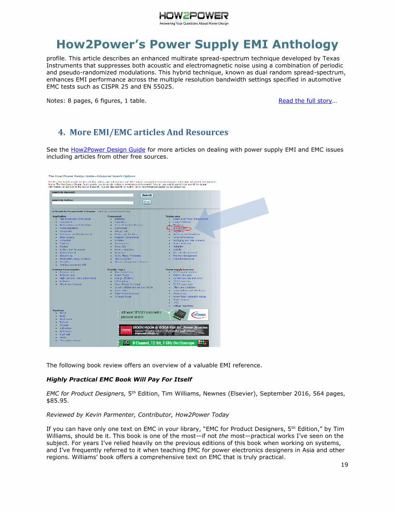
See the How2Power Design Guide for more articles on dealing with power supply EMI and EMC issues including articles from other free sources.
The following book review offers an overview of a valuable EMI reference.
Highly Practical EMC Book Will Pay For Itself
EMC for Product Designers, 5th Edition, Tim Williams, Newnes (Elsevier), September 2016, 564 pages,
$85.95.
Reviewed by Kevin Parmenter, Contributor, How2Power Today
If you can have only one text on EMC in your library, “EMC for Product Designers, 5th Edition,” by Tim Williams, should be it. This book is one of the most—if not the most—practical works I’ve seen on the
subject. For years I’ve relied heavily on the previous editions of this book when working on systems,
and I’ve frequently referred to it when teaching EMC for power electronics designers in Asia and other regions. Williams’ book offers a comprehensive text on EMC that is truly practical.

How2Power’s Power Supply EMI Anthology
20
Read this EMC book review…
EMC Wisdom Has A Long Shelf Life
EDN Designers Guide to Electromagnetic Compatibility, Daryl Gerke, PE, and William Kimmel, PE,
available in PDF or hardcopy reprint from Kimmel Gerke Associates.
Reviewed by Kevin Parmenter, Chair, and James Spangler, Co-chair, PSMA Safety and Compliance
Committee
Back in the ‘90s when Kevin was working at Motorola, his company often provided in-house training
for customers to help them get their systems working and into production. One of the works used in these courses was the EDN Designers Guide to Electromagnetic Compatibility, which was authored by
two legends of EMC—Daryl Gerke PE and William Kimmel, PE of Kimmel Gerke Associates. In this
review, Kevin explains why this book is still so valuable to system designers (especially power
electronics designers) almost 25 years after its initial publication. Read this EMC book review…
All-In-One Test Solution Accelerates EMI/EMC Pre-Compliance Testing
Tektronix’s EMCVu is an all-in-one EMC pre-compliance solution for measuring radiated emissions and
conducted emissions as well as for EMI troubleshooting & debug. A detailed article introducing this product appeared in How2Power Today.
Notes: 4 pages, 2 figures, 2 tables. Read the full story…
Power Magnetics Roundup: EMI Filters
This Focus on Magnetics column frequently focuses on the application of magnetic components in switched-mode power supply (SMPS) circuits where inductors, transformers and coupled inductors
play a critical role in power processing. However, magnetics also serve another purpose in SMPSs
within the EMI filters installed on power supply inputs. By attenuating the switching noise produced by the power supply, EMI filters enable compliance with conducted EMI standards. This article offers news
about EMI filter modules introduced over the course of this year.
Notes: 5 pages. Read the full story…
An Introduction To Medical Regulations: Understanding The 60601 Standard
by Kevin Parmenter, Chair, and James Spangler, Co-chair, PSMA Safety and Compliance Committee
Abstract: This article aims to give an initial introduction to the rules and regulations that govern
safety and compliance in medical equipment. This basic information does not go into details of medical
power supplies. Rather, an attempt is made to enlighten those not familiar with the medical
regulations and standards, including designers and specifiers of medical power supplies. In particular, we aim to shed light on the importance of medical equipment immunity from radiated and conducted
electromagnetic emissions. Medical regulations are complex because they apply to the safety of both
patients and medical practitioners. The 60601 standard, which is the focus here, applies to most locations throughout the world, and anywhere medical equipment is used: operating rooms, hospital
rooms, intensive care units, nurseries, senior care facilities and even households.
Notes: 4 pages, 1 figure, 1 table. Read the full story…
Explaining The ROI Of Compliance Efforts To Your Colleagues
by Kevin Parmenter, Chair, and James Spangler, Co-chair, PSMA Safety and Compliance Committee
How2Power’s Power Supply EMI Anthology
21
Abstract: In this column, we frequently stress the need to plan for compliance requirements—all types including safety, EMC, energy efficiency and environmental/restricted materials—early in the
product design cycle or process. We stress the need to know the requirements and to perform pre-
compliance testing as you go through the different design stages. But knowing we should do these
things, and getting our companies to agree to do them are different things. So often there is resistance from other members of a design team, or other colleagues in the organization, to take the
necessary extra steps to ensure that compliance needs are considered throughout product
development. How do we overcome this resistance? A paper presented at the recent IEEE EMC + SIPI 2019 conference provides guidance on how compliance advocates can convince their colleagues in
engineering and management of the value, or more specifically, the return on investment (ROI) of
addressing compliance needs early and throughout the product design process.
Notes: 3 pages, 1 figure. Read the full story…
EMC+SIPI Symposium Offered Practical Instruction, Latest Equipment And R&D
by David G. Morrison, Editor, How2Power.com
Abstract: EMC+SIPI is not your average IEEE conference. I discovered this while attending the most
recent edition of the IEEE International Symposium On Electromagnetic Compatibility, Signal Integrity and Power Integrity, held July 22-26, 2019 in New Orleans. While this symposium included numerous
papers on the designated topics, its greater emphasis seemed to be on providing professional
instruction on these topics. Instead of allotting just a day or two for classes prior to the event, EMC + SIPI spread workshops and tutorials across three days of its five-day program. Some of the
educational content was presented within the Clayton R. Paul Global University, which offered eight
tutorials on broad topics. The instructive nature of the symposium even extended to the expo which showcased, all types of instrumentation, and electronic and mechanical equipment or accessories used
in EMC testing plus software for modeling and analysis of EMC.
Notes: 5 pages, 1 table. Read the full story…
Power Supply Book Also Explains EMI And EMC Requirements
Power Supplies Explained, Paul Lee, G3ZKO, published by the Radio Society of Great Britain,
September 11, 2018, 531 pages, $24.95 from ARRL, also available for Kindle from Amazon.
Reviewed by Kevin Parmenter, Chair, and James Spangler, Co-chair, PSMA Safety and Compliance Committee
Abstract: Paul Lee’s very practical book on the broader subject of power supplies also contains very useful information on EMI and EMC. “Power Supplies Explained” provides explanations on the causes
of electromagnetic intereference in its various forms, techniques for identifying and mitigating the
sources of EMI, applicable regulations, and other details that can help working engineers get their products to market faster. In his review of the chapter on EMI and EMC, Kevin recaps what readers
can learn from this discussion while also sharing his experiences in getting power converters to pass
regulatory requirements.
Notes: 3 pages. Read the full story…
EMC+SIPI Symposium Shares Valuable Tutorials Virtually
by Kevin Parmenter, Chair, and James Spangler, Co-chair, PSMA Safety and Compliance Committee
Abstract: Each year the IEEE EMC Society holds its annual conference devoted to electromagnetic
compatibility, signal integrity and power integrity. As is the case with many events, the IEEE EMC + SIPI Symposium is going virtual this year with all presentations being given online. As a result, in lieu
of the traditional one-week format, conference sessions have been spread out over the course of a
How2Power’s Power Supply EMI Anthology
22
month, from August 3rd through the 28th. This virtual format could be a boon for many attendees as
it allows individuals to attend more sessions live. Nevertheless, the conference is so large that you cannot attend every presentation live. So the IEEE EMC Society has made a provision for those who
register to view the sessions on-demand from September 1-30, 2020. The authors are both in the
process of attending the symposium. This article contains their overview of the week one sessions with
Jim’s comments on those he has attended.
Notes: 5 pages. Read the full story…
WBG Semiconductors Pose Safety And EMI Challenges In Motor Drive Applications
by Kevin Parmenter, Chair, PSMA Safety and Compliance Committee
Abstract: For years we’ve been told that silicon (Si) power MOSFETs and IGBTs have largely reached
their performance limits and that wide-bandgap (WBG) power semiconductors such as SiC and GaN MOSFETs will soon take over. One area where this is supposed to happen is in variable-speed motor
drives, where SiC MOSFETs are competing with silicon IGBTs to be the power switch of choice for
driving permanent magnet synchronous motors (PMSMs). GaN FETs are also being positioned for use in these applications. Despite the hype, there are serious obstacles to overcome in making the WBG
power switches viable in motor drive applications.
Notes: 4 pages Read the full story…
One Month Left To Download EMC + SIPI 2021 Proceedings
by James Spangler, Contributor, How2Power.com
Abstract: Due to COVID-19, the EMC + SIPI symposium was held virtually again this year, from July 27 through August 20, 2021. As always, this year’s conference program was full of useful information
relating to EMC, signal integrity and power integrity topics. Members of the IEEE EMC Society were
recently sent a reminder that they have until December 15, 2021 to access the conference
proceedings here. If you are not a member of the EMC Society, but are already an IEEE member, you can join the society for a modest fee. See the society membership page. This article is a short
overview and summary of the EMC + SIPI 2021 symposium to help you to navigate the workshops,
tutorials and technical papers that are available in this year’s proceedings.
Notes: 5 pages. Read the full story…


![[a worship poetry anthology] - Free-eBooks.net](https://static.fdokumen.com/doc/165x107/631e51c725add517740afcfd/a-worship-poetry-anthology-free-ebooksnet.jpg)