Homocysteine, vitamin B 12 and folic acid levels in psoriasis patients
13
WIND POWERED PUMPED HYDRO STORAGE SYSTEMS 1
Transcript of Homocysteine, vitamin B 12 and folic acid levels in psoriasis patients

WIND POWERED PUMPED HYDRO STORAGE SYSTEMS
1
1- THE WIND 1-1 The Wind and the Wind Power
Air masses move because of the different thermalconditions of these masses. The motion of air masses can be aglobal phenomenon (i.e the jet stream) as well as a regionaland local phenomenon. The regional phenomenon is determined byorographic conditions (e.g. the surface structure of the area)as well as by global phenomena.
Wind turbines utulise the wind energy close to theground. The wind conditions in this area, known as boundarylayer, are influencedby the energytransferred from theundisturbed hihg energy stream of geostrotopic wind to thelayers below as well as by regional conditions. Owing torughness of the ground, the local wind stream near the groundis turbulent.
The wind speed varies constiniously as a function of timeand height. Variable speed wind turbines , for instance , mayabsorb short-term power variations by immediate storege ofenetgy in the rotating masses of wind turbine drive train. Thatmeans the power output is smoother than for strongly grid-coupled turbines. And also wind speed forecast playsignificiant role for the long term balancing of power system.
Anathor important issue is that the long term variationsof wind resources. There are several studies regarding thisissue. It has been estimated that the variation of yearly meanpower output in a period to the next has standard deviationapproximately ten percentage or less than. Hence , over thelife time of wind turbine , the uncertainity of the resourcewind is not large, which is an impoetant factor for theeconomic evaluation of wind turbine. In many location of theworld, the uncertanity regarding the availability of water oflonger time period for hydropower generation exceed that ofwind power.
2

The power of wind ; the power of an air mass that flows atspeed V through an area A can be calculated this method:
Power in wind=12ρA V3(watts)
This is the formula of wind power with respect to ρ is airdensity (kg.m−3),the intercepting area A and velocity V. Theair density is a funtion of air tempreture ,which both arefunctions of the height above see level:
ρ=P0
RTe
(−gzRT
)
Po=standard sea level atmospheric density(1.225 kg.m−3);
R=specific gas constant for air (287.05 JkgK);
g=gravity constant (9.81 ms2);
z=altitude above sea level (m);
The power in the wind is total avliable energy per unit oftime. The power in the wind converted into the mechanichal androtational energy of the wind turbine rotor, which results in areduced speed n the air mass. The power in the wind cannot beextracted completely by wind turbine, as the air mass would bestopped completely in the intersepting rotor area. Those are somany losses and the power has been lossed. And we can assumethe extracted power 59 percantage accordind to Betz. He wasexplain that in 1926.
Power Curve
The avaliable energy in the wind varies with the cube ofthe wind speed. For example when the speed of ind increased 10percent the power increased 30 percent.
3

The power curve of a wind turbine follows thisrelationship between cut-in wind speed and rated capacity ,approximately the wind turbine usually reaches rated capacityt
at a wind speed 12-16 m s−1 , depending on the design ofindividual wind turbine.
Figure 1.1 typical power curve of regulated wind turbine
At wind speeds higher than the rated wind speed, themaximum power production will be limited , or , in other words,some parts of the avaliable ennergy in th wind will be‘spilled’. The power output regulation can be achieved withpitch-control or with stall control. Hence, a wind turbineproduces maximum power within a certain wind interval that hasits upper limit at the cut-out wind speed. The cut-out windspeed is the wind speed where the wind turbine stops productonand turns out of the main wind direction. Typically , the cut-out wind speed is in the range of 20 to 25 m s−1.
The power curve depends on the air pressure. The powercurve of fixed-speed , stall-regulated wind turbines can alsobe influenced by the power system frequency.
Finally , the power curve of a wind farm is notoutomatically made up of the scaled –up power curve of turbinesof the wind firm., owing to the shadowing or wake effectbetween the turbines. For istance , if wind turbines in firstrow of turbines that directly face the main wind direction
4

experience wind speeds of 15m/s , the last row may ‘get ’ only10m/s. Hence , the wind turbines in the first row will operateat rated capacity, 1500 kW for the turbine in above figure,wheras the last row will oparete at less than rated capacity.
1-2-History of The Wind Turbines
Windmills were used in Persia (present-day Iran) as earlyas 200 B.C. The wind wheel of hero of Alexandre marks one ofthe first known instances of wind powering a machine inhistory. However, the first known practical windmills werebuilt in Sistan, an Eastern province of Iran, from the 7thcentury. These "panemone" were vertical axle windmills, whichhad long vertical drive shaft with rectangular blades. Made of
six to twelve sails covered in reed matting or cloth material,these windmills were used to grind grain or draw up water, andwere used in the gristmilling and sugarcane industries.
Windmills first appeared in Europe during the middle ages.The first historical records of their use in England date tothe 11th or 12th centuries and there are reports ofGerman crusaders taking their windmill-making skills to Syriaaround 1190.By the 14th century, Dutch windmills were in use todrain areas of the Rhine delta.
The first electricity-generating wind turbine was abattery charging machine installed in July 1887 by Scottish
5
academic James Blyth to light his holiday home in Marykirk,Scotland. Some months later American inventor Charles F. Brushbuilt the first automatically operated wind turbine forelectricity production in Cleveland, Ohio Although Blyth'sturbine was considered uneconomical in the UnitedKingdom electricity generation by wind turbines was more costeffective in countries with widely scattered populations.
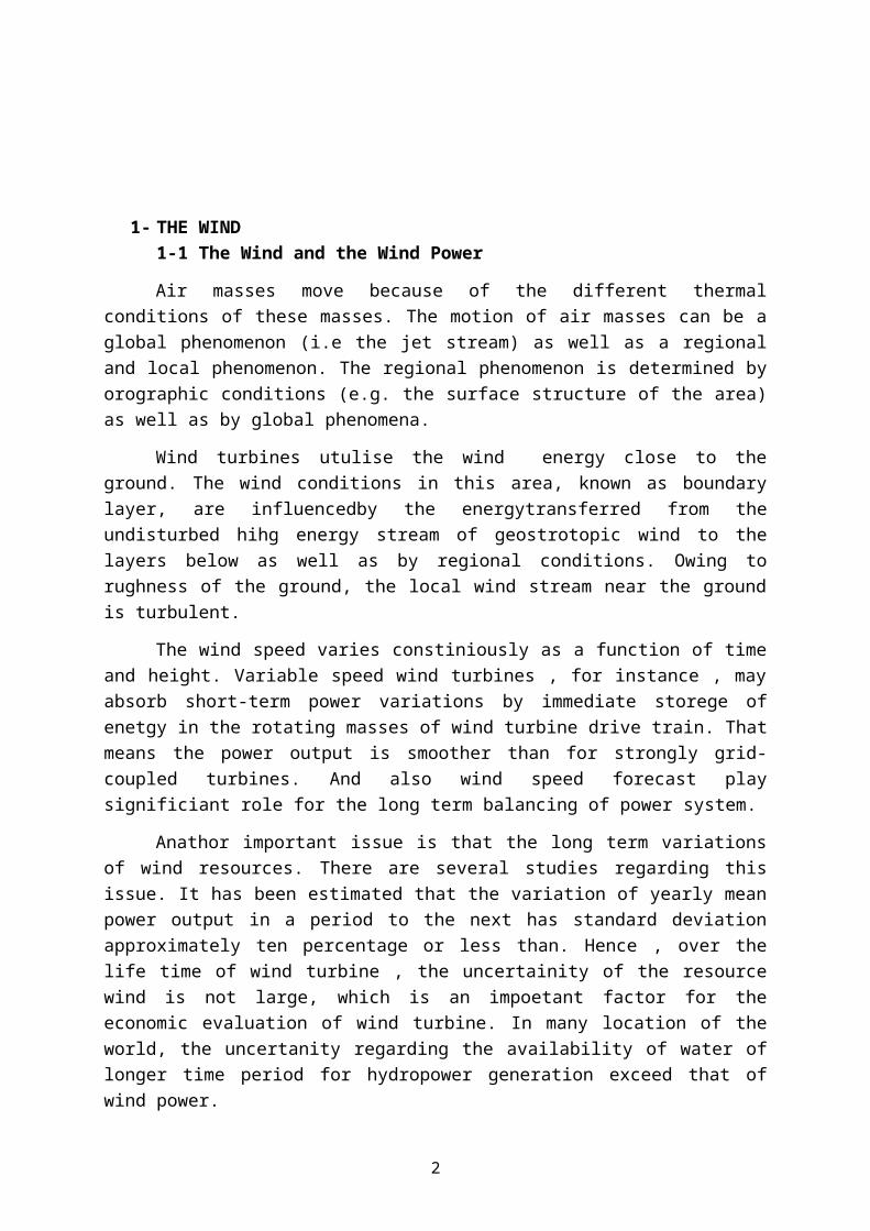
In Denmark by 1900, there were about 2500 windmills formechanical loads such as pumps and mills, producing anestimated combined peak power of about 30 MW. The largestmachines were on 24-meter (79 ft) towers with four-bladed 23-meter (75 ft) diameter rotors. By 1908 there were 72 wind-driven electric generators operating in the United States from5 kW to 25 kW. Around the time of World War I, Americanwindmill makers were producing 100,000 farm windmills eachyear, mostly for water-pumping.
Figure 1-2 The first automatically operated wind turbine,built in Cleveland in 1887 by Charles F. Brush. It was 60 feet(18 m) tall, weighed 4 tons (3.6 metric tones) and powered a12 kW generator.
By the 1930s, wind generators for electricity were commonon farms, mostly in the United States where distributionsystems had not yet been installed. In this period, high-tensile steel was cheap, and the generators were placed atopprefabricated open steel lattice towers.
6

A forerunner of modern horizontal-axis wind generators wasin service at Yalta, USSR in 1931. This was a 100 kW generatoron a 30-meter (98 feet) tower, connected to the local 6.3 kVdistribution system. It was reported to have an annual capacityfactor of 32 percent, not much different from current windmachines.
In the autumn of 1941, the first megawatt-class windturbine was synchronized to a utility grid in Vermont.The Smith-Putnam wind turbine only ran for 1,100 hours beforesuffering a critical failure. The unit was not repaired,because of shortage of materials during the war.
The first utility grid-connected wind turbine to operatein the UK was built by John Brown & Company in 1951 inthe Orkney Islands.
Despite these diverse developments, developments in fossilfuel systems almost entirely eliminated any wind turbinesystems larger than super micro size. In the early 1970s,however, anti-nuclear protests in Denmark spurred artisanmechanics to develop micro turbines of 22 kW. Organizing ownersinto associations and co-operatives lead to the lobbying of thegovernment and utilities and provided incentives for largerturbines throughout the 1980s and later. Local activists inGermany, nascent turbine manufacturers in Spain, and largeinvestors in the United States in the early 1990s then lobbiedfor policies that stimulated the industry in those countries.Later companies formed in India and China. As of 2012, Danishcompany Vestas is the world's biggest wind-turbinemanufacturer.
1-3-Types of The Wind Turbines
1-3-1-Horizontal axis1-3-2-Vertical axis
7
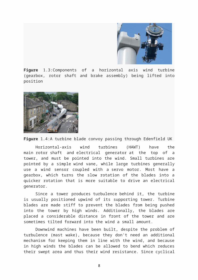
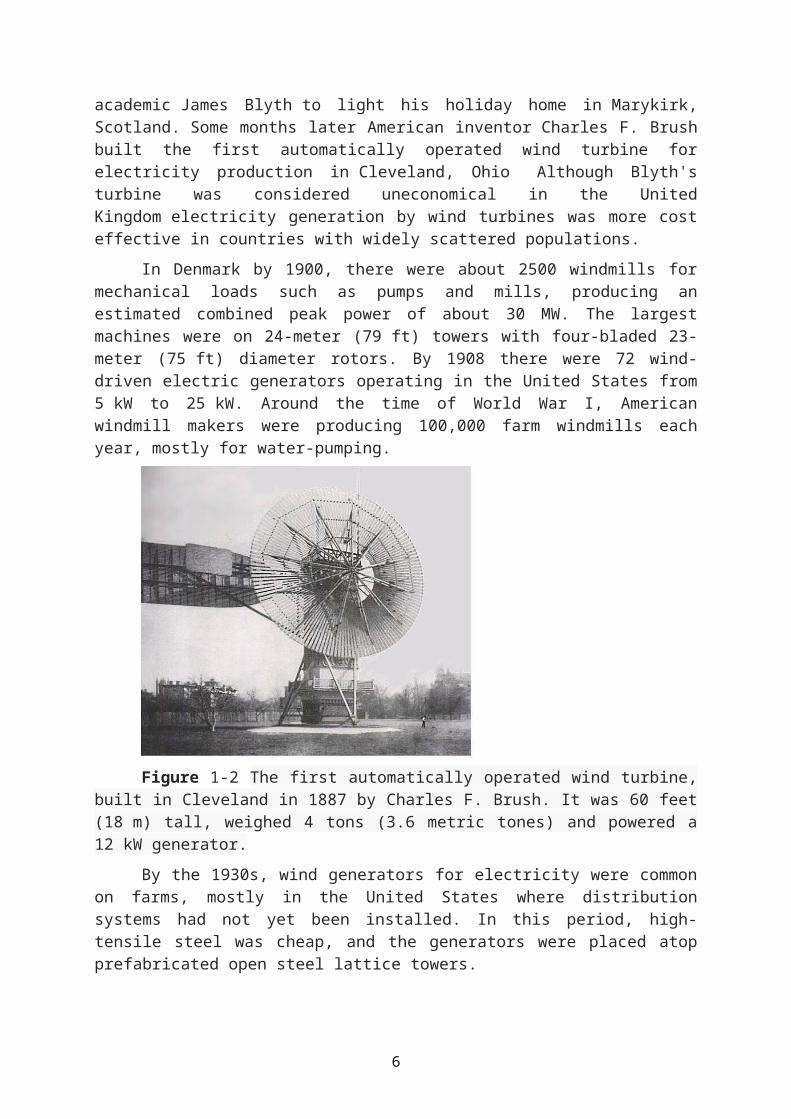
Figure 1.3:Components of a horizontal axis wind turbine(gearbox, rotor shaft and brake assembly) being lifted intoposition
Figure 1.4:A turbine blade convoy passing through Edenfield UK
Horizontal-axis wind turbines (HAWT) have themain rotor shaft and electrical generator at the top of atower, and must be pointed into the wind. Small turbines arepointed by a simple wind vane, while large turbines generallyuse a wind sensor coupled with a servo motor. Most have agearbox, which turns the slow rotation of the blades into aquicker rotation that is more suitable to drive an electricalgenerator.
Since a tower produces turbulence behind it, the turbineis usually positioned upwind of its supporting tower. Turbineblades are made stiff to prevent the blades from being pushedinto the tower by high winds. Additionally, the blades areplaced a considerable distance in front of the tower and aresometimes tilted forward into the wind a small amount.
Downwind machines have been built, despite the problem ofturbulence (mast wake), because they don't need an additionalmechanism for keeping them in line with the wind, and becausein high winds the blades can be allowed to bend which reducestheir swept area and thus their wind resistance. Since cyclical
8

(that is repetitive) turbulence may lead to fatigue failures,most HAWTs are of upwind design.
Turbines used in wind farms for commercial production ofelectric power are usually three-bladed and pointed into thewind by computer-controlled motors. These have high tip speedsof over 320 km/h (200 mph), high efficiency, and low torqueripple, which contribute to good reliability. The blades areusually colored white for daytime visibility by aircraft andrange in length from 20 to 40 meters (66 to 131 ft) or more.The tubular steel towers range from 60 to 90 meters (200 to300 ft) tall. The blades rotate at 10 to 22 revolutions perminute. At 22 rotations per minute the tip speed exceeds 90meters per second (300 ft/s).A gear box is commonly used forstepping up the speed of the generator, although designs mayalso use direct drive of an annular generator. Some modelsoperate at constant speed, but more energy can be collected byvariable-speed turbines which use a solid-state power converterto interface to the transmission system. All turbines areequipped with protective features to avoid damage at high windspeeds, by feathering the blades into the wind which ceasestheir rotation, supplemented by brakes.
Vertical-axis wind turbines (or VAWTs) have the main rotorshaft arranged vertically. One advantage of this arrangement isthat the turbine does not need to be pointed into the wind tobe effective, which is an advantage on a site where the winddirection is highly variable. It is also an advantage when theturbine is integrated into a building because it is inherentlyless steerable. Also, the generator and gearbox can be placednear the ground, using a direct drive from the rotor assemblyto the ground-based gearbox, improving accessibility formaintenance.
The key disadvantages include the relatively lowrotational speed with the consequential higher torque and hencehigher cost of the drive train, the inherently lower powercoefficient, the 360 degree rotation of the aerofoil within thewind flow during each cycle and hence the highly dynamicloading on the blade, the pulsating torque generated by somerotor designs on the drive train, and the difficulty ofmodelling the wind flow accurately and hence the challenges of
9

analyzing and designing the rotor prior to fabricating aprototype.
When a turbine is mounted on a rooftop the buildinggenerally redirects wind over the roof and this can double thewind speed at the turbine. If the height of a rooftop mountedturbine tower is approximately 50% of the building height it isnear the optimum for maximum wind energy and minimum windturbulence. Wind speeds within the built environment aregenerally much lower than at exposed rural sites, noise may bea concern and an existing structure may not adequately resistthe additional stress.
Figure 1-5 Turbines and where there are using
1-4-The Wind Turbine PartsThe wind turbines have many parts to working synchronously
each other. the part are listed below.-Anemometer-Blades-Brake-Controller-Gear box
10

-Generator-High-speed shaft-Low-speed shaft-Nacelle-Pitch-Rotor-Tower-Wind vane-Yaw drive and motor
Figure 1-6 The turbine Parts-Anemometer: Measured the wind speed and transmits wind speeddata to the controller.-Blades: Lift and rotates when wind is blown over them, causingthe rotor to spin. Most turbines have either two or threeblades.-Brake: Stops the rotor mechanically, electrically,hydraulically, in emergencies.-Controller: Starts up the machine at wind speeds of about 13to 25 kilometer per hours(kph) and shuts off the machine at
11

about 88 kph. Turbines do not operate at wind speeds aboveabout 88 kph because they may be damaged by the high winds.-Gear box: Connects the low-speed shaft to the high-speedshaft and increases the rotational speeds from about 30-60rotations per minute (rpm), to about 1,000-1,800 rpm; this isthe rotational speed required by most generators to produceelectricity. The gear box is a costly (and heavy) part of thewind turbine and engineers are exploring "direct-drive"generators that operate at lower rotational speeds and don'tneed gear boxes.-Generator: Produces 60-cycle AC electricity; it is usually anoff-the-shelf induction generator.-Nacelle: Sits atop the tower and contains the gear box, low-and high-speed shafts, generator, controller, and brake. Somenacelles are large enough for a helicopter to land on.-Pitch: Turns (or pitches) blades out of the wind to controlthe rotor speed, and to keep the rotor from turning in windsthat are too high or too low to produce electricity.-Rotor: Blades and hub together form the rotor.-Tower: Made from tubular steel , concrete, or steel lattice.Supports the structure of the turbine. Because wind speedincreases with height, taller towers enable turbines to capturemore energy and generate more electricity.-Wind direction: Determines the design of the turbine. Upwindturbines—like the one shown here—face into the wind whiledownwind turbines face away.-Wind vane: Measures wind direction and communicates with theyaw drive to orient the turbine properly with respect to thewind.-Yaw drive and motor: Orients upwind turbines to keep themfacing the wind when the direction changes. Downwind turbinesdon't require a yaw drive because the wind manually blows therotor away from it. The yaw motor is that power the yaw drive.
12
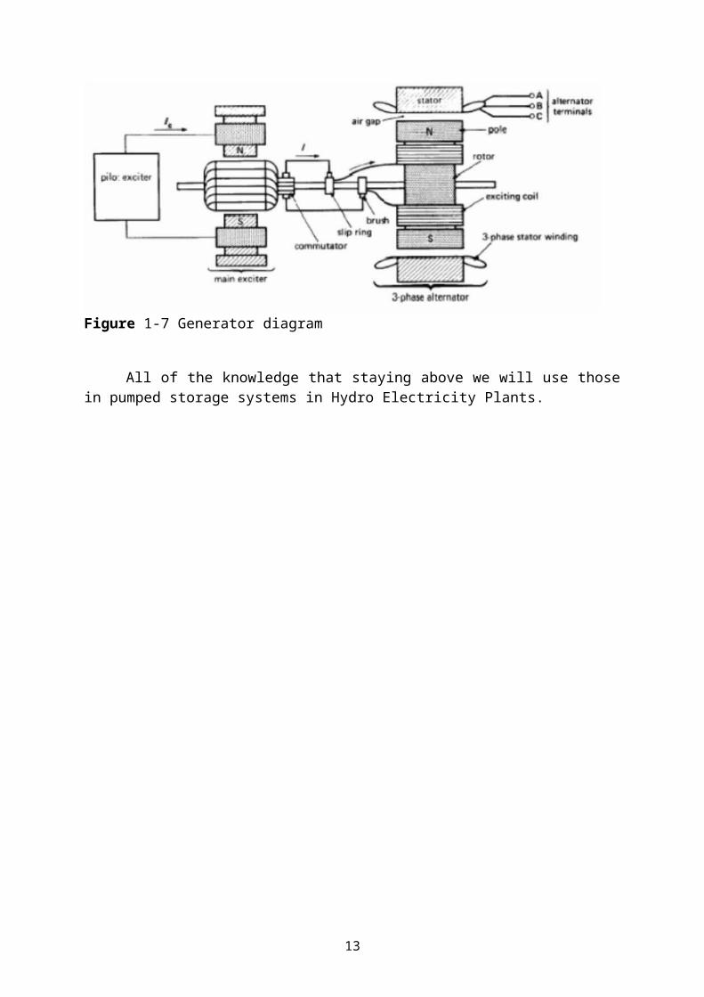
Figure 1-7 Generator diagram
All of the knowledge that staying above we will use thosein pumped storage systems in Hydro Electricity Plants.
13