High-level mobility controller for a remotely operated unmanned land vehicle
15
High Level Mobility Controller for a Remotely Operated Unmanned Land Vehicle Sandor Szabo, Harry A. Scott, Karl N. Murphy, Steven A. Legowik and Roger V. Bostelman Systems Integration Group Robot Systems Division National Institute of Standards and Technology Gaithersburg, MD 20899 Abstract The U.S. Army Laboratory Command, as part of the Department of Defense Robotics Testbed Program, is developing a testbed for cooperative, real-time control of unmanned land vehicles. The program entails the development and integration of many elements which allow the vehicles to perform both autonomous and teleoperated functions. The National Institute of Standards and Technology (NIST) is supporting this program by developing the vehicle control system using the Real-time Control System (RCS) architecture. RCS is a hierarchical, sensory- based control system, initially developed for the control of industrial robots and automated manufacturing systems. NIST is developing the portions of RCS that control all vehicle mobility functions, coordinate the operations of the other subsystems on the vehicle, and communicate between the vehicle and the remote operator control station. This paper reviews the overall control system architecture, the design and implementation of the mobility and communication functions, and results from recent testing. This work is funded by the U.S. Army Laboratory Command. This paper was prepared by U.S. Governme employees and is not subject to copyright. Equipment listings do not imply a recommendation by NIST.
-
Upload
independent -
Category
Documents
-
view
1 -
download
0
Transcript of High-level mobility controller for a remotely operated unmanned land vehicle

High Level Mobility Controller for a Remotely
Operated Unmanned Land Vehicle
Sandor Szabo, Harry A. Scott, Karl N. Murphy, Steven A. Legowik and Roger V. Bostelman
Systems Integration Group
Robot Systems Division
National Institute of Standards and Technology
Gaithersburg, MD 20899
Abstract
The U.S. Army Laboratory Command, as part of the Department of DefenseRobotics Testbed Program, is developing a testbed for cooperative, real-timecontrol of unmanned land vehicles. The program entails the development andintegration of many elements which allow the vehicles to perform both autonomousand teleoperated functions. The National Institute of Standards and Technology(NIST) is supporting this program by developing the vehicle control system usingthe Real-time Control System (RCS) architecture. RCS is a hierarchical, sensory-based control system, initially developed for the control of industrial robots andautomated manufacturing systems. NIST is developing the portions of RCS thatcontrol all vehicle mobility functions, coordinate the operations of the othersubsystems on the vehicle, and communicate between the vehicle and the remoteoperator control station. This paper reviews the overall control system architecture,the design and implementation of the mobility and communication functions, andresults from recent testing.
This work is funded by the U.S. Army Laboratory Command. This paper was prepared by U.S. Governmentemployees and is not subject to copyright. Equipment listings do not imply a recommendation by NIST.

Introduction
Artificial intelligence, control technology, and vision processing capabilities have not reached thepoint where robotic land vehicles can function autonomously in off-road tactical situations.Therefore, the vehicle control systems must support a mix of capabilities ranging from master-slave teleoperation to autonomous control. The development of such a control system is underwayas part of a program initiated by the U.S. Army Laboratory Command. This program, called theRobotics Testbed for Unmanned Ground Vehicles (RT), is a joint effort between several U.S.Army organizations, national laboratories, and commercial contractors. The goal of the program isto develop and demonstrate technology for use on tactical vehicles in the areas of mobility, sensoryprocessing, target detection and tracking, and communications.
In the RT scenario, humans remotely operate several Robotic Combat Vehicles (RCVs) from anOperator Control Unit (OCU). Each vehicle contains: actuators on the steering, brake,transmission, etc.; an inertial navigation system (INS); a mission package which performs targetdetection, tracking, and laser designation; and data and video communication links. The OCUcontains controls and displays for route planning, driving, operation of the mission package, andcontrol of the communication links.
Atypical mission includes a planning phase where the operator plans a route using a digital terraindata base. The operator then remotely drives the vehicle to a desired location as the vehicle recordsthe route using INS data. The operator activates the mission package for automatic targetdetection, and when a target is detected, the mission package designates the target with a laser.The vehicle then automatically retraces the route, a process termed retro–traverse.
The RT control architecture follows the Real-time Control System (RCS) methodology developedat National Institute of Standards and Technology (NIST) [1-3]. The application of RCStechnology to the RT program is presented in Reference [4] and the control system architecturedeveloped for the RT program is presented in Reference [5]. The RCS architecture is a hierarchyof control modules in which each module controls one or more modules at the next lower level.High-level commands are decomposed into simpler commands as they pass down through thelevels. Each control module is composed of task decomposition, world modeling, and sensorprocessing. Task decomposition implements real-time planning, control, and monitoringfunctions. It decomposes tasks both spatially and temporally. The sensory processing modulesdetect, filter, and correlate sensory information. The world modeling modules estimate the state ofthe external world and make predictions and evaluations based on these estimates.
This paper focuses on the implementation of the mobility RCS on the vehicle testbed and presentsresults of mobility tests performed. The first section provides an overview of the control systemarchitecture for the entire system. Next, the design sections of this paper present the details of themobility and the communication subsystems. The implementation section describes the currentstate of the mobility and communication control systems. The final section presents initial resultsobtained from testing performed at the U.S. Army Aberdeen Proving Grounds, Aberdeen,Maryland.
Control Architecture
The RCS architecture for RT is an inverted tree structure containing several levels. Figure 1shows the control modules that reside on each RCV and Figure 2 shows the modules that reside inthe OCU. The highest control module on each vehicle is the RCV Supervisor. It coordinates threesubsystems: mobility, mission package, and communication.
The mobility subsystem drives the vehicle and gathers sensory information for the operator in theOCU. At the Servo level, the Vehicle Platform Controller drives independent actuators that

position the steering wheel, accelerator pedal, brake pedal, and other linkages. The Primitive(PRIM) level Mobility Platform Controller generates smooth trajectories in a convenient coordinateframe based on either goals from the operator or from prerecorded paths. The Elemental(EMOVE) level Mobility Subsystem Controller computes paths that are clear of obstacles.Although the current goals for RT do not include automatic generation of obstacle free paths,future developments in this area would occur at this level.
The automatic target acquisition (ATA) control modules in the mission package subsystemautomatically detect, locate, and laser designate moving tanks and other targets [6]. The ATAfunctions are divided among control modules for processing imaging sensors, infrared detectors,and nonimaging sensors, as well as modules for controlling leveling and aiming platforms.
The communications subsystem controls data and video communications between the RCVs andthe OCU. The data communication modules provide data paths between modules on the vehiclesand the OCU using a single radio link. The video modules utilize compression techniques toreduce the radio link bandwidth requirements while maintaining sufficient feedback to theoperators for teleoperation.
mobilityvideo
controller
mission packsubsystemcontroller
mission packagesubsystem
mobilitysubsystem
to OCU
RCV1Supervisor
commosub-
system
TASK
EMOVE
PRIM
SERVO
DEVICE designator nonimagingsensors
vehicleactuators
obstaclesensors
platformactuators
imagingsensors
platformactuators
platformactuators
navigationsensors
datatx/rx
videotx
videodevice
controller
datadevice
controller
navigationsensor
controller
vehicleplatform
controller
obstaclesensor
controller
videoplatform
controller
designatorcontroller
imagingsensor
controller
nonimagingsensor
controller
levelingplatform
controller
imagingplatform
controller
mobilityplatform
controller
mobilitysubsystemcontroller
ATAimaging
controller
ATAnonimaging
controller
videocommo
controller
datacommo
controller
to Vehicle 2
Figure 1. Control system architecture for RT Robotic Combat Vehicles.

GROUP
TASK
EMOVE
PRIM
SERVO
DEVICE datatx/rx
videorx
operator station 1subsystem
GroupSupervisor
OCUSupervisor
to vehicles
datadevice
controller
videodevice
controller
datacommo
controller
videocommo
controller
operatorstation 1controlle
r
operatorstation 2controller
mobility devices
mobilitydevice
controller
mobilitystation
controller
mission packdevices
mission packdevice
controller
mission packstation
controller
mappingdevices
mappingdevice
controller
mappingstation
controller
Figure 2. Control system architecture for Operator Control Unit.
The highest-level control module in the RT architecture, the Group Supervisor, resides in theOCU. This module coordinates activities that involve multiple vehicles such as convoydeployment and cooperative target detection. Beneath the Group Supervisor, the OCU Supervisorcoordinates activities between two operator station subsystems. Each operator station subsystemcontains joysticks, displays, video monitors, etc., that allow the operator to drive the vehicle andto control the mission package. Included in each operator station subsystem are thecommunication controllers required to maintain video and data communication with the vehiclebeing controlled.
Initially, the architecture is a tool for analyzing functions of the system and designing the varioussubsystems. The next step is to perform a detailed design of the modules that make up asubsystem. The guideline for detailed designs specifies further breakdown of control modulesinto sensor processing (SP), world modeling (WM) and task decomposition (TD) and establishingthe flow of information between these sub-modules. The functions performed by the taskdecomposition sub-module is further divided to enable parallel operations between planning andexecution. The Job Assigner (JA) spatially decomposes tasks between planners. Each planner(PL) decomposes tasks temporally in order to achieve goals within a planning horizon. While theplanner looks ahead in time, the executor (EX) works in parallel to achieve immediate goals. Forfurther details on these modules see Reference [3]. The architecture and guidelines fordevelopment of an RCS were the basis for the detailed design efforts for the mobility andcommunications subsystems discussed next.
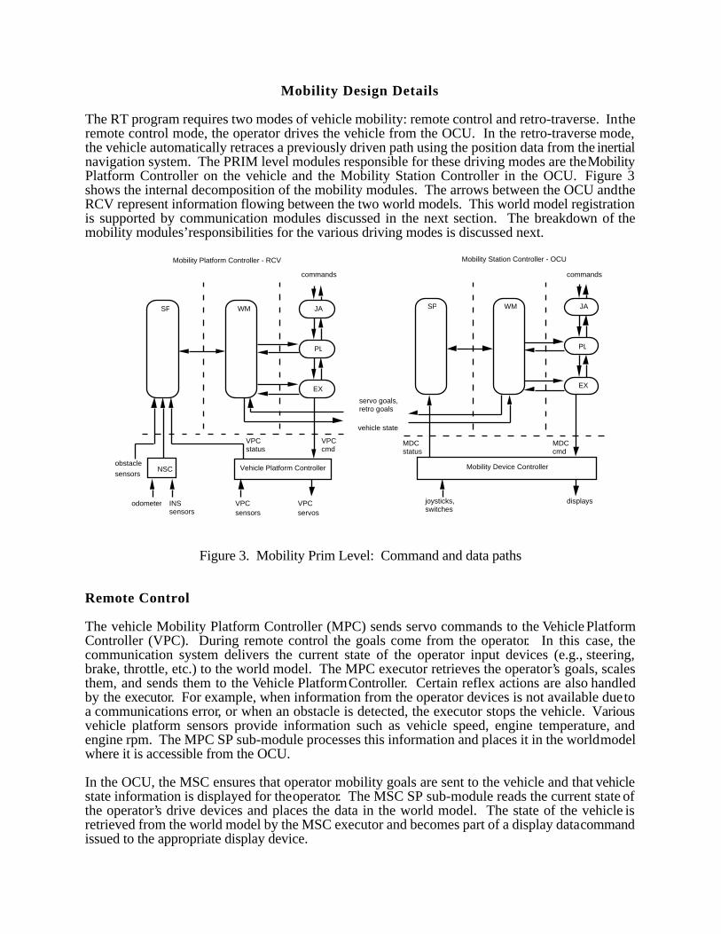
Mobility Design Details
The RT program requires two modes of vehicle mobility: remote control and retro-traverse. In theremote control mode, the operator drives the vehicle from the OCU. In the retro-traverse mode,the vehicle automatically retraces a previously driven path using the position data from the inertialnavigation system. The PRIM level modules responsible for these driving modes are the MobilityPlatform Controller on the vehicle and the Mobility Station Controller in the OCU. Figure 3shows the internal decomposition of the mobility modules. The arrows between the OCU and theRCV represent information flowing between the two world models. This world model registrationis supported by communication modules discussed in the next section. The breakdown of themobility modules’responsibilities for the various driving modes is discussed next.
joysticks,switches
displays
MDCcmd
MDCstatus
vehicle state
servo goals,retro goals
Mobility Station Controller - OCU
WM JA
PL
EX
SPWM JA
PL
EX
VPCcmd
VPCstatus
VPCservos
VPCsensors
Vehicle Platform ControllerNSC
INS sensors
odometer
Mobility Platform Controller - RCV
SP
obstacle
sensors
commands commands
Mobility Device Controller
Figure 3. Mobility Prim Level: Command and data paths
Remote Control
The vehicle Mobility Platform Controller (MPC) sends servo commands to the Vehicle PlatformController (VPC). During remote control the goals come from the operator. In this case, thecommunication system delivers the current state of the operator input devices (e.g., steering,brake, throttle, etc.) to the world model. The MPC executor retrieves the operator’s goals, scalesthem, and sends them to the Vehicle Platform Controller. Certain reflex actions are also handledby the executor. For example, when information from the operator devices is not available due toa communications error, or when an obstacle is detected, the executor stops the vehicle. Variousvehicle platform sensors provide information such as vehicle speed, engine temperature, andengine rpm. The MPC SP sub-module processes this information and places it in the world modelwhere it is accessible from the OCU.
In the OCU, the MSC ensures that operator mobility goals are sent to the vehicle and that vehiclestate information is displayed for the operator. The MSC SP sub-module reads the current state ofthe operator’s drive devices and places the data in the world model. The state of the vehicle isretrieved from the world model by the MSC executor and becomes part of a display data commandissued to the appropriate display device.

Retro-traverse
The retro-traverse mode of driving gives the RT vehicles some degree of autonomy during amission. Initially, a path (i.e., a sequence of x-y positions) is recorded as the operator remotelydrives the vehicle. Then, at a later time, the vehicle retraces the path without the direct control ofthe operator. This is analogous to teach programming and playback commonly used by industrialrobots.
During the teach phase, the mobility control system functions in the remote control mode. Inaddition, the Mobility Platform Controller world model records the path based on navigation dataacquired by the MPC sensor processor. The data may be produced by different types ofnavigation systems, but the source is transparent at this level in sensor processing. At the end ofthe path, the operator halts the path recording and specifies a turn around maneuver that avoidsobstacles.
Later in the mission, the operator initiates the autonomous drive phase of retro-traverse. The MPCplanner retrieves the turn around maneuver from the world model, selects the appropriate gear andcommands the steering either hard left or right. Path following begins once the vehicle’sapproximate heading is close to the path. The MPC planner retrieves the path and the vehicle’scurrent position and orientation from the world model. Using a PID controller, the plannercontinuously generates new throttle and brake commands to maintain the desired speed, similar toan automobile cruise control. Steering commands are calculated that drive the vehicle along thepath using a “pure pursuit” steering algorithm [7].
The pure pursuit method is a simple yet very stable method for controlling vehicle trajectory. Eachcycle the turn radius, and hence the steering angle, is selected to drive the vehicle over a point onthe path a specified distance ahead of the vehicle. The relationship between the vehicle and thepath is shown in Figure 4. No regard is given to the orientation of the vehicle at this goal point ifthe vehicle were to maintain the selected steering angle. During the next control cycle a newsteering angle is calculated using a new goal point.
Current Path Segment
Current Goal Point, (x, y) in
the vehicle frame. Moves
with the vehicle
y
x
Constant Look Ahead Distance
Turn Radius, r = x2 + y2
2 y
Figure 4. The goal point is the point on the prerecorded path a given distance aheadof the vehicle. The turn radius, and hence the steering angle, is selected to drive thevehicle over the goal point. The goal point, turn radius, and steering angle areupdated each control cycle as the vehicle moves.

If the goal point is at (x,y) in the vehicle frame, as shown in Figure 4, then the center of the turncircle is (0, –r) and
r = x2 + y2
2y
The steering angle is inversely proportional to r. When r is negative the vehicle turns left andwhen it is positive the vehicle turns right.
Communication Design Details
Both video and data communication are required between the OCU and the vehicles. Thetransmission of video signals for driving requires high-bandwidth communications which isundesirable in tactical operations. Data compression techniques will be used to reduce the quantityof video data transmitted. Work in this area is presented in Reference [8]. For datacommunication, a single rf (radio frequency) link carries all information between the vehicle andOCU. Four categories of information are multiplexed on the single data channel. The categoriesare time-critical, emergency, time-noncritical, and development.
Time-critical data is transmitted frequently, often at a fixed rate, and between processes that cannottolerate large transmission delays. This class includes servo goals used for driving (steer, brake,and throttle) and for manual control of the mission package platform. This class represents themost demanding communication occurring on the rf link.
Emergency messages are time-critical but are transmitted infrequently. These messagescommunicate emergency stop commands to the vehicle and emergency status from the vehicle.
Time-noncritical data is transmitted relatively infrequently and not with real-time urgency.Examples include file transfers, commands that set various vehicle modes, such as gear selection,and high level command and status exchanges.
The development data supports code development, downloading, process monitoring, anddebugging. This information may be exchanged at any time, including during vehicle operation.
Figure 5 illustrates how the communication functions are integrated into the RT architecture. TheData Device Controllers serve all RCV-OCU data communications. Any relevant portions of thevehicle and OCU world models may be transmitted over the rf link. Several vehicle and OCUcontrol modules will require this type of communication. Shown here is an example ofinformation flow during the remote control driving mode. Vehicle state information flows fromthe vehicle Mobility Platform Controller to the RCV Data Device Controller, over the rf link to theOCU Data Device Controller, and finally to the OCU Mobility Station Controller. A similar path isused, in the opposite direction, to convey vehicle goal states from the OCU to the vehicle.

DataCommand
EX
PL
JA
WMSP
Receiver Transmitter
WM
JA
PL
EX
Data Device Controller - RCV
SP
Receiver Transmitter
toMobilityStationControllerworldmodel
Data Device Controller - OCU
from MobilityPlatformControllerworld model
rf link
Figure 5. Data Communications between the RCV and OCU.
When new vehicle state information is detected in the Mobility Platform Controller world model, itis passed to the vehicle Data Device Controller world model. An inter-process communications(IPC) mechanism, which will be discussed later, is used to facilitate communication betweenprocesses. The executor obtains this data, prepares the appropriate message structure for it andexecutes the control functions required to transmit the rf message. It also monitors feedback fromthe radio that indicates its performance.
In the current design, the job assigner and planner establish the remote operation mode, whichresults in the information flow described above. In other hardware configurations the job assignerwould distribute information over several separate radio equipment interfaces and the plannerwould select schemes to optimize communications.
The information transmitted from the vehicle radio is detected by the OCU receiver and retrievedby the OCU Data Device Controller sensor processor. The executor evaluates the reception and, asa result of certain error conditions, may report failures to the Prim level Data CommunicationsController. The vehicle state information is then sent to the Mobility Station Controller worldmodel via the IPC mechanism.
Inter-Process Communications
The inter-process communication mechanism is a set of utilities supporting mailbox-typecommunication between processes in an RCS application. It provides a consistent user view forcommunications, while hiding the various underlying mechanisms employed. Process-to-process,board-to-board, and subsystem-to-subsystem communications benefit from a standardcommunication interface. The underlying communication techniques include socket-based andcommon memory-based methods.
The IPC user can connect to a mailbox using a symbolic name, send variable length messages to a

mailbox, and synchronize control processes through appropriate use of blocking reads. A readoperation may be directed to block (with a timeout period) for synchronization, or may be non-blocking. Double buffering and internal semaphoring free the control processes from concernabout overwriting a previous message. These capabilities provide a communication mechanismparticularly well suited to an RCS environment and their ease of use encourages modularization ofthe system code.
Implementation
Several organizations are involved in the development of the RT control system. An importantconsideration in such an endeavor is integration of the individual subsystems that function in boththe vehicle and the OCU. The system architecture, if properly designed and implemented, assistsin the integration and serves as a useful tool for managing the testbed. Figure 6 shows theportions of the control system (highlighted) that were implemented for the U. S. Army MaterielCommand (AMC) Technology Symposium at Aberdeen Proving Grounds on October 1-4, 1990.Demonstrated at the Symposium were teleoperation of the vehicle from a remotely situated driverstation, recording vehicle trajectories, displaying vehicle trajectories on a map display, andexecuting retro-traverse.
videorx
operator station 1subsystem
GroupSupervisor
OCUSupervisor
datadevice
controller
videodevice
controller
datacommo
controller
videocommo
controller
operatorstation 1controller
mobilitydevice
controller
mobilitystation
controller
mappingdevices
mappingdevice
controller
mappingstation
controller
RCV1Supervisor
commosub-
system
videotx
videodevice
controller
datadevice
controller
navigationsensor
controller
vehicleplatformcontroller
mobilityplatform
controller
mobilitysubsystemcontroller
videocommo
controller
datacommo
controller
to Vehicle 2
to OSC 2
RCVs OCU
TASK
EMOVE
PRIM
SERVO
DEVICE
GROUP
vehicleactuators
datatx/rx
datatx/rx
mobility devices
navigationsensors
mobilitysubsystem
Figure 6. Portions of control system implemented for teleoperated driving and retro-traverse.

Several modules shown in Figure 6 exist as commercial products, thus eliminating the need forin–house development. The Vehicle Platform Controller module and vehicle actuators weredeveloped by Kaman Sciences. Two types of navigation sensors are used in the testbed. TheU.S. Army Modular Azimuth and Position System (MAPS) uses accelerometers, an odometer,and optical ring laser gyros to sense vehicle inertial positions and orientations. Asecond navigationsystem, the Radio Frequency Navigation Grid (RFNG) provides vehicle position data duringtesting and development. The RFNG employs radio beacons placed at the corners of the test areawhich emit timing pulses received by the vehicle. Differences in phase information from eachtransmitter are used to compute vehicle position. Velocity and heading are derived by differencingposition. For information on both MAPS and RFNG see Reference [9].
The data radio system is composed of components developed by Telesystems SLW Inc. Theradios employ a direct sequence, spread spectrum modulation technology. They operate at915 MHz, with a spread of 26 MHz and a maximum power output of 1 watt. The system isconfigured as nodes in a network with eight nodes on the vehicle connected to eight nodes in theOCU via the single RF link. Each node supports error-free communication over an asynchronousRS-232 serial interface at individually configurable rates of up to 19.2 kbaud. A singlecomponent, known as a network unit, is used at the vehicle and at the OCU to provide the eightnodes. One of the eight vehicle-OCU connections is used to connect the an ethernet local areanetwork (LAN) on the vehicle to a LAN on the OCU by way of the Serial Line Interface Protocol(SLIP). This essentially provides a bridge function between the two LANs. The network unitsatisfied the requirements of the Data Device Controllers (see Figure 6) by providing suchfunctions as multiplexing of different information categories over the single RF link, errordetection and retransmission, and control of the data radio transceiver.
Analog video information is provided from a vehicle camera and sent through a Coherent videotransmitter and is received by a common VHF receiver in the OCU for display on a monitor.
In lieu of a fixed-base driver station, NIST developed a portable unit called the Mobility ControlStation (MCS). The MCS provides the functionality of the Mobility Devices and Mobility DeviceController modules specified in the OCU portion of the system architecture (see Figure 6). Shownin Figure 7, the MCS consists of a steering wheel, a joystick for brakes and throttle (and for use asan alternate steering device), several switches for controlling ignition, transmission, transfer case,etc., and a display for vehicle status. The display also provides a touch screen which offersflexibility in programming various switches, and in alternating between remote driving,retro–traverse and debug modes. A small, stand-alone data acquisition computer inside the MCShandles data acquisition of the mobility devices and controls the mobility display.
The vehicle used for the Robotics Testbed is the U. S. Army’s High Mobility MultipurposeWheeled Vehicle (HMMWV). The HMMWV is a one and one quarter ton, four wheel drive truck.The vehicle is shown in Figure 8. A sealed, passively cooled enclosure houses a shock mounted19-inch electronics rack containing the control system computers and the radios.

Figure 7. The NIST developed portable Mobility Control Station.
Figure 8. The Robotics Testbed vehicle, a standard U.S. Army HMMWV.

The high-level computing environment selected to implement the control system utilizes a real-time, multi-tasking, UNIX-like operating system, VxWorks (Wind Rivers Systems), for the targethardware, and a separate UNIX system (Sun Microsystems) for software development. Thetarget hardware is based on Motorola CPUs interconnected by VME backplanes. Individualbackplanes are typically connected using an ethernet local area network (LAN). Code is developedon Sun workstations and downloaded to a battery backed RAM disk over the LAN, or over theradio using the Serial Line Interface Protocol. The RAM disk allows the on-board computers toboot without connecting to the Sun’s or requiring that application code be stored in PROM.
This environment is highly suited for an RCS application. For example, referring to the detaileddesign presented earlier, the Mobility Platform Controller is implemented as several modular tasksrunning on a single board computer as shown in Figure 9. The tasks interfacing to the NavigationSensor Controller modules continuously update the world model estimation of the vehicleposition. The task containing the job assigner, planner, and world modeling is responsible forrecording and planning vehicle trajectories used during retro-traverse. The final task interfacing tothe Vehicle Platform Controller is responsible for generating the servo level commands for theKaman Sciences vehicle controller. These goals are derived from the operator during teleoperationor from the planner during retro-traverse. Note the distribution of sensor processing, worldmodeling and task decomposition between several tasks as opposed to a single task for each. Thisapproach is taken to maximize software performance and to hide the details of interfaces to externalequipment.
SP WM EX SP WM EX SP WM EX
PL
JA
NIU KamanSciences
Mobility Platform ControllerMVME 147 Computer
WM(x,y)altituderoll, pitch, yaw
Servo status
steeringthrottlebrake
maps response
query
steeringthrottlebrake
steeringthrottlebrake
RFNG
(x,y)speedheading
Dma, Dmbma#, mb#
Navigation Sensor Controller
Vehicle Platform Controller
to MobilityStationController
VxWorksTask
JA - Job AssignerPL - PlannerEX - ExecutorWM - World ModelSP - Sensor Processor
to MobilityStationController
Legend
query
Figure 9. Mapping the mobility platform controller into a multi-tasking operating system.

Results
Both remote control and retro-traverse functions were demonstrated during the TechnologySymposium at Aberdeen Proving Grounds and additional testing is ongoing. The performancecharacterization of remote control was limited to measuring delays in the control system anddetermining limitations of the communication system. The Kaman Sciences controller acceptedactuator commands at a 60 msec update. The MCS was capable of acquiring the state of theoperator devices and displaying the status of the vehicle at a 60 msec update. The radio linkexperienced delays of 30 msec in each direction when operated multiplexed with the other serialports. The radio link automatically attempts retransmission upon errors which adds significantdelays. Initial testing indicates that the transmission characteristics of this radio system providedrange up to 1.5 km, and at ranges of a few kilometers, exhibited little performance degradationwhen obstacles such as clumps of trees or small buildings were in the direct line of sight. Theeffective update rate for vehicle teleoperation, including optimization whereby communicationsand display updates are done in parallel, totaled 160 msec. Subjective opinions by several driversindicated that the control system was sluggish in avoiding obstacles at speeds in excess of 32 kph(20 mph). Several approaches to minimizing the delays are presently under investigation. Morecontrolled testing will be conducted jointly with the Human Engineering Laboratory in the future.
The effectiveness of retro-traverse depends on the repeatability of the navigation system and theperformance of the control algorithms. The MAPS, and an associated Navigation Interface Unit(NIU), provides 3-D position and orientation at 25 Hz with drift of 0.1% of distance traveled. TheRFNG system provides position updates at 20 Hz with 0.1 meter repeatability (no drift).
The pure pursuit method was used to steer the vehicle during retro-traverse as described in theMobility Design Details section. With this method, the vehicle followed the path accurately andwas stable at speeds up to 64 kph (40 mph) during straight stretches of road with good surfaces.The goal point’s look-ahead distance was varied to determine the optimum value. Large valuescaused the vehicle to cut corners, while small values caused the controller to become unstable athigh speeds. A look-ahead distance of 5 meters is used for speeds below 24 kph and 10 metersfor speeds up to 64 kph.
Results for a test run are shown in Figure 10. The look-ahead distance is 5 meters and the speedranges from 8 kph in the sharp turns to 24 kph on the straighter portions. Note the vehicle cuts thesharp corners slightly and is 0.5 meters off course during the sharp turns. The average distancethat the vehicle is off the path is 0.1 meter RMS.
Asecond steering algorithm was tested. In this case, the steering angle was set proportional to theperpendicular distance the vehicle was from the path, the speed that it was approaching the path,the heading error, and heading rate. This PD steering controller produced large errors in pathfollowing and proved unstable at speeds above 16 kph (10 mph). For a path similar to that inFigure 10, the average distance the vehicle was off the path was 0.8 meter RMS.

Figure 10. The “pure pursuit” steering algorithm with look ahead distance of 6meters and speeds ranging from 8 to 24 kph. Dimensions are in meters.
Summary
The control system for the Robotics Testbed requires the development and integration of manyelements which allow two vehicles to perform autonomous and teleoperated functions under thecontrol of an operator from a remote site. NIST is supporting this program by developing thevehicle control system based on their Real-time Control System. The RCS is a hierarchical,sensory-based control system, initially developed for the control of industrial robots andautomated manufacturing systems. In this application, the RCS controls all vehicle mobilityfunctions, coordinates the operations of other subsystems on the vehicle, and communicatesbetween the vehicle and the remote operator control station.
To date, the architecture has been defined in terms of the major functional modules. Ahigh levelcomputing environment supports development of the modules. The mobility and communicationsmodules required to support remote control and retro-traverse driving have been implemented.Initial results indicate that remote control functions adequately at low speeds but future work isneeded to improve the overall system throughput. Retro-traverse testing has shown promise in theability to accurately control the vehicle based on inertial navigation sensors. Future work willconcentrate on improving the accuracy and update rates of the control and navigation systems.

References
[1] Albus, J. S., Barbera, A. J., and Nagel, R. N., Theory and Practice of HierarchicalControl, Proceedings of the Twenty-third IEEE Computer Society International Conference,Washington, DC, September 15-17, 1981.
[2] Barbera, A. J., Fitzgerald, M. L., Albus, J. S., and Haynes, L. S., RCS: The NBSReal-Time Control System, Proceedings of the Robots 8 Conference and Exposition, Volume 2 -Future Considerations, Detroit, MI, June 4-7, 1984.
[3] Albus, J. S., McCain, H. G., and Lumia, R., NASA/NBS Standard Reference Model forTelerobot Control System Architecture (NASREM), NIST Technical Note 1235, 1989 Edition,National Institute of Standards and Technology, Gaithersburg, MD, April 1989 (supersedes NBSTechnical Note 1235, July 1987).
[4] Szabo, S., Scott, H. A., and Kilmer, R. D., Control System Architecture for the TEAMProgram, Proceedings of the Second International Symposium on Robotics and ManufacturingResearch, Education and Applications, Albuquerque, NM, November 16-18, 1988.
[5] Szabo, S., Scott, H. A., Murphy, K. N., and Legowik, S. A., Control SystemArchitecture for a Remotely Operated Unmanned Land Vehicle, Proceedings of the 5th IEEEInternational Symposium on Intelligent Control, Philadelphia, PA, September 5-7, 1990.
[6] David, P., Balakirsky, S., and Hillis, D., A Real Time, Automatic Target AcquisitionSystem, Proceedings of AUVS-90, Dayton, OH, July 30 - August 1, 1990.
[7] Omead, A., Integrated Mobile Robot Control, M.S Thesis, Carnegie Mellon University,May, 1990.
[8] Herman, M., Chaconas, K., Nashman, M., and Hong, T., Low Data Rate RemoteVehicle Driving, Proceedings of the Third IEEE International Symposium on Intelligent Control,Arlington, VA, August 24-26, 1988.
[9] Kraetz, W.F., Application of Robotic Convoy Technology to Combat Training Centers -Phase I, Report Number 7-90-3, Honeywell Defense Systems Group, Edina, MN, May 11, 1990.