Design of a Roller-Collector Remotely Operated Vehicle
7
Design of a Roller-Collector Remotely Operated Vehicle A. Yandell, J. Austin-Breneman, B. Brett, H. Brundage, J. Downey, S. Fantone, T. Pennington, S.Sheppard, M. J. Stanway, T. Stefanov-Wagner, Massachusetts Institute of Technology Massachusetts Institute of Technology, Ocean Engineering Department 77 Massachusetts Avenue, 5-225 Cambridge, MA 02139 USA [email protected] Abstract- The Roller-Collector Remotely Operated Vehicle (RC-ROV) was designed to compete in the interscholastic Marine Advanced Technology Education Center (MATE) ROV competition. The objective of the competition was to build an ROV which would enter a mock shipwreck and collect as many objects as possible within a time limit. The most prominent feature of the RC-ROV is the roller collection system. This system consists of two foam rollers that rotate into each other in order to catch and funnel objects into a collection basket. This collection system was chosen because of its simplicity, effectiveness, and ease of use. The vehicle utilizes a fast and easy drive-over collection method which eliminates the need for fine positioning of the vehicle or of the collection mechanism. The electronic controls of the RC-ROV are also designed for simplicity. Using a “brute-force” approach, all of the motors and cameras are wired through a subsurface breakout box directly to a topside controller. The RC-ROV has two thrusters in each of the vertical, forward, and lateral axes in order to maximize speed and maneuverability. These thrusters can be paired, such that a pair operating in unison provides directional movement along the axis it governs. By operating the motors in opposition, the ROV can be maneuvered to pivot and make directional turns. The RC-ROV has two cameras, one forward-looking and one back- looking. The forward camera is to aid in both steering and confirmation that a probe has been captured. The rear camera aids in looking behind to see that no probes have been missed in a sweep over the room. The RC-ROV design concept could be expanded and improved upon to create an efficient and inexpensive vehicle for underwater use in fields such as mining and deepwater archaeology. The roller concept could be used as a substitute or in conjunction with other collection systems that are commonly used today. The RC-ROV is simple to operate and do not require much pilot training. Roller shape and positioning can be varied to fit specific jobs. The RC-ROV can also operate in reverse to shuttle cargo to underwater construction sites. Other improvements are likely to be found for the RC-ROV as its low cost, simplicity of design, and ease of use make it very attractive when compared to other, more complicated systems. I. INTRODUCTION The Roller Collector Remotely Operated Vehicle (RC-ROV) (Fig. 1) is a unique vehicle which was designed for competition in the Marine Advanced Technology Education Center (MATE) Remotely Operated Vehicle (ROV) 12-25 class competition. The competition challenges teams to enter a mock “Titanic” shipwreck and collect “sea probes” to be carried to the surface within a time limit. The competition dictates only three design constraints: ROV’s must use no more than 12 volts and 25 amps, and must be able to fit into a 61 square centimeter (2 ft 2 ) cube. The wreck is simulated by a structure made of 3.81 centimeter (1.5 in) PVC pipe. The structure is 2.4 meters long x 1.8 meters wide x 1.8 meters high (8 ft x 6 ft x 6 ft) and has two inside decks. Each deck has a corridor and two rooms located side by side each with an entrance coming from the corridor. The structure’s bulkheads are fabricated from plastic mesh. A 61 square centimeter (2 ft 2 ) entrance to the Titanic is located on the top of the structure and leads to the corridor of the upper deck. Directly below this entrance is an opening which connects the corridors of the upper and lower decks. This opening is identical to the entrance to the upper deck. Each room has a 61 square centimeter (2 ft 2 ) entrance as well. Fig. 1: the Roller-Collector Remotely Operated Vehicle (RC-ROV) top, side, and front views. Special thanks to our sponsors: American Brush Company, Cape Shores Welding, Carrillo Underwater Systems, ExxonMobile, and Pigs Unlimited, Inc.
Transcript of Design of a Roller-Collector Remotely Operated Vehicle

Design of a Roller-Collector Remotely Operated Vehicle
A. Yandell, J. Austin-Breneman, B. Brett, H. Brundage, J. Downey, S. Fantone, T. Pennington, S.Sheppard, M. J.Stanway, T. Stefanov-Wagner, Massachusetts Institute of Technology
Massachusetts Institute of Technology, Ocean Engineering Department77 Massachusetts Avenue, 5-225
Cambridge, MA 02139 [email protected]
Abstract- The Roller-Collector RemotelyOperated Vehicle (RC-ROV) was designed tocompete in the interscholastic Marine AdvancedTechnology Education Center (MATE) ROVcompetition. The objective of the competition wasto build an ROV which would enter a mockshipwreck and collect as many objects as possiblewithin a time limit.
The most prominent feature of the RC-ROV isthe roller collection system. This system consistsof two foam rollers that rotate into each other inorder to catch and funnel objects into a collectionbasket. This collection system was chosenbecause of its simplicity, effectiveness, and ease ofuse. The vehicle utilizes a fast and easy drive-overcollection method which eliminates the need forfine positioning of the vehicle or of the collectionmechanism.
The electronic controls of the RC-ROV are alsodesigned for simplicity. Using a “brute-force”approach, all of the motors and cameras are wiredthrough a subsurface breakout box directly to atopside controller.
The RC-ROV has two thrusters in each of thevertical, forward, and lateral axes in order tomaximize speed and maneuverability. Thesethrusters can be paired, such that a pair operatingin unison provides directional movement along theaxis it governs. By operating the motors inopposition, the ROV can be maneuvered to pivotand make directional turns. The RC-ROV has twocameras, one forward-looking and one back-looking. The forward camera is to aid in bothsteering and confirmation that a probe has beencaptured. The rear camera aids in looking behindto see that no probes have been missed in a sweepover the room.
The RC-ROV design concept could be expandedand improved upon to create an efficient andinexpensive vehicle for underwater use in fieldssuch as mining and deepwater archaeology. Theroller concept could be used as a substitute or inconjunction with other collection systems that arecommonly used today. The RC-ROV is simple tooperate and do not require much pilot training.Roller shape and positioning can be varied to fitspecific jobs. The RC-ROV can also operate inreverse to shuttle cargo to underwater constructionsites. Other improvements are likely to be foundfor the RC-ROV as its low cost, simplicity of design,and ease of use make it very attractive whencompared to other, more complicated systems.
I. INTRODUCTION
The Roller Collector Remotely Operated Vehicle(RC-ROV) (Fig. 1) is a unique vehicle which wasdesigned for competition in the Marine AdvancedTechnology Education Center (MATE) RemotelyOperated Vehicle (ROV) 12-25 class competition. Thecompetition challenges teams to enter a mock “Titanic”shipwreck and collect “sea probes” to be carried to thesurface within a time limit. The competition dictatesonly three design constraints: ROV’s must use no morethan 12 volts and 25 amps, and must be able to fit intoa 61 square centimeter (2 ft2) cube.
The wreck is simulated by a structure made of 3.81centimeter (1.5 in) PVC pipe. The structure is 2.4meters long x 1.8 meters wide x 1.8 meters high (8 ft x6 ft x 6 ft) and has two inside decks. Each deck has acorridor and two rooms located side by side each withan entrance coming from the corridor. The structure’sbulkheads are fabricated from plastic mesh. A 61square centimeter (2 ft2) entrance to the Titanic islocated on the top of the structure and leads to thecorridor of the upper deck. Directly below this entranceis an opening which connects the corridors of the upperand lower decks. This opening is identical to theentrance to the upper deck. Each room has a 61square centimeter (2 ft2) entrance as well.
Fig. 1: the Roller-Collector Remotely Operated Vehicle (RC-ROV)top, side, and front views.
Special thanks to our sponsors: American Brush Company, Cape Shores Welding, Carrillo Underwater Systems,ExxonMobile, and Pigs Unlimited, Inc.

Twenty “sea probes” are located inside the Titanic.These probes are similar to dive sticks and are made of1.27 centimeter (0.5 in) PVC pipe with caps at eachend. They are weighted at the bottom so that theystand upright. At the top of the probes are PVC rings.The goal of the competition is to pick up as many seaprobes as possible within a 20 minute time frame. Eachprobe is assigned a point value so that probes deeperwithin the “Titanic” or in a difficult to reach position areworth more points than those at an easily accessiblelocation. All probes are located within the structure.
II. DESIGN
A. Global ConsiderationsThe RC-ROV was designed with two key
considerations in mind. The first design considerationwas that the RC-ROV would accomplish its objectivequickly. It was designed to pick up the maximumnumber of sea probes in a minimal amount of time.Hence, the vehicle needed to be fast and maneuverableand have a probe retrieval system that could beoperated easily.
Secondly, the ROV needed a simple, robust designso that it would be less likely to break and easier to fixthan a more complicated system. This wasaccomplished by the use of primarily solid (non-jointed)pieces and few moving parts. Spinning rollers werefound to be a good choice to minimize the number ofcomponents (moving or static) used in the collectionsystem. Rollers were also found to be very sturdy andless likely to break than many other possible collectionsystems.
The vehicle’s frame was designed to account forthe above considerations (Fig. 2). The frame wasdesigned to be small in comparison to a 61 centimetercube (2 ft3), sturdy, and light enough to be carried byhand. The small size aids in maneuverability and a lowweight makes the vehicle easy to transport and workwith when out of the water.
Fig. 2: Frame Diagrams (side, back, top) with rollers displayed in blueand a sea probe displayed in gray.
A frame design was chosen with roller attachmentson the front of the vehicle. A box built into the framewas to be used as a collection basket. On the top ofthe vehicle were “wings” to which thrusters, buoyancy,electronics, cameras and anything else that becamenecessary could be mounted. The frame was made outof 7.62 centimeter (_”) Aluminum tubing weldedtogether into a single solid piece.
The use of several small thrusters aided inmaneuverability and also eliminated the need for amovable thruster. Six thrusters were chosen so thateach of the x, y, and z axes would have a pair ofthrusters for movement. With two thrusters per axis,the thrusters could be made to work either in unison orin opposition to provide thrust or torque along eachaxis.
B. RollersThe most distinctive feature of the RC-ROV is the
roller system for sea probe collection. The rollers are aunique and innovative solution to the task of gatheringsea probes, providing several advantages such asspeed and robustness. The roller system has a simpledesign, consisting of two foam cylinders (“rollers”)mounted onto cylindrical shafts which are rotated bytwo motors. One cylinder rotates clockwise along itsvertical axis and the other rotates counterclockwisesuch that the two rollers rotate into each other (Fig. 3a).
The rollers are mounted at an angle so that they tiltforward allowing them to grab sea probes from the top(Fig. 3b). The collection technique of grabbing a probefrom the top accounts for the presence of a cup inwhich the probes are placed that would present aproblem for purely vertical rollers.
The cylinders are actuated by two 69 RPM 0.91Newton-meters (8 in-lbf) torque motors positioned at thetop of the shafts that run down the center of eachcylinder. The cylinders are mounted on the front of thevehicle and the vehicle is driven directly over a probethat is to be collected while the rollers spin and grab theprobe. Once collected, the sea probes are pushed intoa mesh collection basket located in the center of thevehicle behind the rollers.
The RC-ROV’s roller system has a very simpledesign and requires minimal attention during operation.The roller collection system allows the pilot to focusprimarily on vehicle movement because the rollers canbe controlled with an on/off switch. This simplifiedoperation makes probe collection faster and easier thancompetitive systems because the pilot has few systemsto juggle while collecting a probe. The rollers can alsooperate in reverse and expel the contents of thecollection basket in case debris is accidentallycollected.
There are very few parts involved in the rollersystem (Fig. 3c) and this simplicity reduces theirprobability of failure. The weakest and most complexpart of the system is the joint between the motor shaftand the roller shaft. This connection was made with a

a b
c
Fig. 3: (a) Roller rotation. (b) Angle of roller tilt and example ofgrabbing a sea probe from the top. (c) Full roller assembly. Partsinclude foam cylinders, cylinder shaft, two motors, and mounting
plates.
shaft extension coming from the motor shaft.Setscrews and the alignment of the motors with the toproller plate were the most fragile parts of thisconnection. Other potential problems with the rollersystem were motor strain due to drag and the glue sealbetween the rollers and the shaft.
For future applications, a variable angle of tilt on therollers may be useful. Also, the ability to move therollers closer together or further apart (laterally) and theability to move them forward and backwards could beuseful. Variable speed motors are also envisioned forfuture uses. With these improvements, the RC-ROVcould be used to collect objects of various sizes andshapes or objects in difficult to reach areas.
None of these improvements were implemented onthe RC-ROV because they added more complexity thanwas necessary for the vehicle’s mission. The rollerswere mounted in a fixed position and required nooperational control (aside from an on/off switch); hence,the pilot could focus more on locomotion than the taskof probe collection.
This lack of complexity allowed for the developmentof the “drive-over” collection method whereby the pilotapproaches a probe with the vehicle, turns on therollers and then drives through the probe—keeping theview of the probe near the center of the camera’s view.This collection method is highly efficient and addsconsiderably to the rate at which sea probes can becollected. It virtually eliminates the need to stop, hover,or execute fine positioning during probe collection asmany other systems require.
The drive-over collection method is made possibleby several factors. First of all, the rollers can effectively
catch the probe over a 0.1 meter1 (4 in) span betweenthe lateral midlines of the two rollers. As the rollersdrive into a probe, a combination of the friction betweenthe roller and probe and the forward motion of thevehicle create this collection span by essentiallyfunneling the probe into the gap between the tworollers. The probe is then pushed into the collectionbasket. Foam rollers also entrain water; thus, as therollers rotate, they create a fluid flow which funnels intothe gap between the rollers. Hence, probes can bedirected toward the intake of the roller system withoutany physical contact with the rollers.
C. ManeuverabilityThe RC-ROV’s maneuverability comes from six
thrusters mounted in vertical, lateral, and forward pairs.The lateral and forward (horizontal plane) pairs aremade of 300 rpm, 0.18 Newton-meter (25 oz-in) torquemotors combined with a two blade, 0.1 meter (4 in)diameter propeller. The vertical thrusters are made of600 rpm, 0.06 Newton-meter (9 oz-in) torque motorscombined with the same propellers as the horizontalthrusters.
The motors were made waterproof by “potting” withFlexane™, a rubber urethane compound (Fig. 4). The“potting” method of waterproofing was found to befaster, easier, and just as effective as a waterproofhousing for the motors. Mounting plates to attach themotors to the vehicle were bolted onto the face plate ofthe motor and had a slot for a hose clamp to connectthem to the frame of the vehicle. A waterproof seal wasmade between the mounting plates and the motors bydrizzling Flexane between them before they were boltedtogether. The Flexane filled both the bolt holes and theshaft hole to create a watertight seal. The assemblywas then placed into a cylinder partly filled with Flexaneand left to dry. (While drying, the motors were runperiodically in order to minimize friction on the shaft.When dried, the Flexane created a watertight housingaround the motor.
In order to maximize the amount of clear waterseen by the propellers, a shaft extension was used toattach the propellers to the motor shaft. Ahemispherical dome was attached to the opposite endof the horizontal thrusters in order to smooth the flow ofwater over the thruster. (Fig. 5)
Fig. 4: Potting a motor with Flexane™. A mounting plate wasbolted to the motor, and then the assembly was placed into a cylinder
filled with Flexane.
1 The 0.1 meter span (from midline to midline) is an approximatemeasurement determined experimentally during a wet run.

Fig. 5: A fully assembled horizontal thruster.
A similar process was used to pot the vertical androller motors; however, a paint-on material, similar toFlexane, was used rather than a Flexane-filled cylinder.A shaft extension was attached to the shaft of thevertical motors and the propellers were attached ontothe extended shaft.
These six thrusters were placed to maximizemaneuverability of the vehicle and so that each thrusterwould operate in as much clear water as possible toprovide for unobstructed flow (Fig. 6). Two verticalthrusters were placed at the top of the vehicle abovethe electronics box along the axis from the center of therollers to the back of the vehicle (Fig. 6a). Thesethrusters can be used to move the vehicle either up ordown. The motors for these thrusters were chosenusing (1.1) and (1.2) from the Principles of NavalArchitecture2 assuming that approximately 0.45kilograms (1 lb) of thrust was needed to account for theadded weight of the probes and would haveapproximately a 0.1 meter (4 in) diameter propeller.
KT = T/(ρn2D4) (1.1)KQ = Q/(ρn2D5) (1.2)
(KT and KQ are coefficients of torque and thrust, T andQ are torque and thrust forces, ρ is water density, n ismotor RPM, and D is propeller diameter.)
The results of these equations show that in order toavoid the necessity of a variable ballast system, morepowerful motors (compared to the horizontal motors)were needed for vertical movement in order to get thenecessary thrust. When acting in unison, the verticalthrusters served to provide directional movement alongthe vertical axis. When operating solo or in oppositionthey put a torque on the vehicle which serves to tilt thevehicle.
The horizontal thrusters are divided into two pairs,forward and lateral. The forward thrusters are placed atthe back of the vehicle directly under the “wings” of theframe. (Fig. 6b) These thrusters, working in unison,serve to propel the vehicle forward. Working inopposition, the forward thrusters serve to drive thevehicle in either a clockwise or a counterclockwisecircle.
2 John P. Comstock. Principles of Naval Architecture. p. 386 Societyof Naval Architects and Marine Engineers, 1967, New York.
The other pair of horizontal thrusters is the lateralthrusters. These thrusters are placed primarily to aid inturning the vehicle; however, they can also be used tomove the vehicle laterally to the left or to the right. Onethruster is placed at the front of the vehicle on thestarboard side (Fig. 6c). It is attached to the topmounting plate for the rollers. The other is placed at theback of the vehicle on the port side (Fig. 6d). It isattached to the frame at the back corner of thecollection basket at about mid-height of the vehicle.The large distance between the two lateral thrustersprovides the greatest amount of yaw-authority possible.
The combination of these six small motors serves tomake the vehicle maximally maneuverable with motionin each of the x, y, and z axes as well as turning controland some control over tilting motions. The pairing ofthe motors (two per axis) also maximizes control of thevehicle, as one motor per axis could causeunintentional motion in the axis it governs. A movablemotor would add an unnecessary element ofcomplexity; and, having more than two stationarymotors per axis was deemed excessive for a light-weight design.
D. ElectronicsThe RC-ROV control system is fairly simple, relying
on double pull, double throw (DPDT) cross wiredswitches to apply forward and reverse power to themotors. The main power bus is connected to a 12 voltbattery through a 15 amp circuit breaker and distributespower to the control box (Fig. 7) and the two cameras.
Within the control box, power is distributed toseveral switches that control the thruster and rollermotors. The four horizontal thrusters are wired directlythough the tether to their controllers, which form asquare of rocker switches on the top of the control box.
a b
c d
Fig. 6: Propellers highlighted in red. (a) Vertical Thrusters, (b) forwardthrusters, (c) forward lateral thrusters, (d) rear lateral thrusters.
The roller motors are controlled in much the sameway, except that the switch to activate them is mountedon the side of the control box and the circuit has twoLED lights wired into it so that the operator can quicklyascertain the on/off status of the rollers.
The vertical thruster control is also wired to a DPDTswitch mounted on the side of the box. However, thevertical thruster circuit has four, 25 watt resistors thatcan be switched into the circuit in series allowing thepilot to vary the voltage (and thus the power) applied tothe vertical thrusters. Three, 2 ohm resistors and a 1ohm resistor are connected to four single pull, doublethrow (SPDT) switches mounted on the right side of thecontrol box. Pushing a switch down switches in oneresistor, thereby reducing the power delivered to thevertical thrusters. These resistors allow for variablespeed vertical thrusters. The variable speed allows formuch finer control of vertical movement andcompensation for changes in the vehicle weight asprobes are gathered. The vertical thrusters also haveindicator LED lights wired into the control circuit. TheseLED’s are convenient during recovery because theyallow the operator to assure that the vertical thrustersare not running when the ROV is pulled out of thewater.
E. CamerasThe RC-ROV has two cameras, one forward-
looking and one back-looking. The cameras haveinfrared LED’s around the lens, thus eliminating theneed for a secondary light source (Fig. 8). They aredirectly wired to surface monitors through the tether.
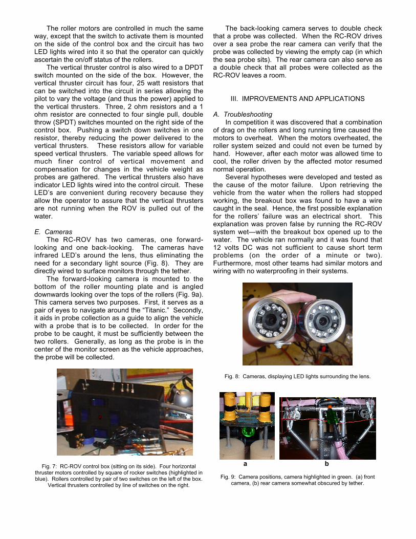
The forward-looking camera is mounted to thebottom of the roller mounting plate and is angleddownwards looking over the tops of the rollers (Fig. 9a).This camera serves two purposes. First, it serves as apair of eyes to navigate around the “Titanic.” Secondly,it aids in probe collection as a guide to align the vehiclewith a probe that is to be collected. In order for theprobe to be caught, it must be sufficiently between thetwo rollers. Generally, as long as the probe is in thecenter of the monitor screen as the vehicle approaches,the probe will be collected.
Fig. 7: RC-ROV control box (sitting on its side). Four horizontalthruster motors controlled by square of rocker switches (highlighted inblue). Rollers controlled by pair of two switches on the left of the box.
Vertical thrusters controlled by line of switches on the right.
The back-looking camera serves to double checkthat a probe was collected. When the RC-ROV drivesover a sea probe the rear camera can verify that theprobe was collected by viewing the empty cap (in whichthe sea probe sits). The rear camera can also serve asa double check that all probes were collected as theRC-ROV leaves a room.
III. IMPROVEMENTS AND APPLICATIONS
A. TroubleshootingIn competition it was discovered that a combination
of drag on the rollers and long running time caused themotors to overheat. When the motors overheated, theroller system seized and could not even be turned byhand. However, after each motor was allowed time tocool, the roller driven by the affected motor resumednormal operation.
Several hypotheses were developed and tested asthe cause of the motor failure. Upon retrieving thevehicle from the water when the rollers had stoppedworking, the breakout box was found to have a wirecaught in the seal. Hence, the first possible explanationfor the rollers’ failure was an electrical short. Thisexplanation was proven false by running the RC-ROVsystem wet—with the breakout box opened up to thewater. The vehicle ran normally and it was found that12 volts DC was not sufficient to cause short termproblems (on the order of a minute or two).Furthermore, most other teams had similar motors andwiring with no waterproofing in their systems.
Fig. 8: Cameras, displaying LED lights surrounding the lens.
a b
Fig. 9: Camera positions, camera highlighted in green. (a) frontcamera, (b) rear camera somewhat obscured by tether.

The next potential explanation was that there was aproblem with the motors themselves. Upon inspectionone of the gear boxes was found to be mildly wet, butthe inside of both motors was completely dry. Hence, awaterproofing problem did not cause the failure either.
The possibility of debris caught in the motors wasalso proven false upon opening the motors forinspection. Another possibility, misalignment, did notseem to be the problem either. Upon inspection, nomisalignment or deformation could be found in eitherthe connection between the motors and roller shafts orwithin the motors themselves.
Another possibility, motor fatigue, may havepartially contributed to the motor failure, however wasmost likely not the primary cause. The vehicle hadbeen in operation for somewhat extended periods oftime both during testing and earlier during the day of thecompetition. However, under normal operatingconditions the motors should have been able to run withno problems for the amount of time that they were inuse.
It was found that the roller motors could beexperimentally overheated by adding drag. This dragwas created by pressing a hand against the rollerswhile they were in operation. During the experiment,the motors’ temperature began to increase whichcaused the motors to stop working. Once the motorsstopped working on the bench, the effects were similarto those that occurred during the competition. Therollers seemed to seize such that they could not beturned electrically or by hand. Once the motors cooleddown the rollers resumed normal operation.
Based on the results of this experiment, it appearsthat drag on the rollers caused resistance to the turningmotor shaft. This resistance caused the motors to workharder and draw more current, hence increasingresistive heating inside the motor. This heat most likelycaused the metal parts (gears and bearings) in themotor to expand enough to prevent movement of theshaft. This failure could potentially have been avoidedby using a higher torque motor or rollers with less drag.
The rollers were made of open-cell foam pigs(generally used to clean oil pipelines) and workedextremely well for collecting objects in both dry and wetenvironments due to their compressibility. Thiscompressibility made the rollers able to grab a seaprobe more effectively than a solid surface would beable to. (Experimental results showed that solidsurfaces tended to push away sea probes whereascompressible foam molded to the shape beingcollected.) Unfortunately, these waterlogged rollersrequired a lot of torque to turn effectively.
For this competition, a less compressible rollermaterial would have been sufficient for probe collection,and would have reduced drag. Drag could also bereduced by a different size of roller. The rollers used inthe competition were bigger than was necessary for thetask in both length and width dimensions. Since thesea probes were being picked up from the top, it was
not necessary for the rollers to extend to the bottom ofthe vehicle. Also, at approximately 10 centimeters (4in) in diameter, the rollers were wider than necessaryfor the purposes of the competition. A smaller diameterroller would have sufficed, and would have allowed for afurther reduction in drag on the rollers and the powerrequired to drive them.
Although the RC-ROV is small compared to the 61cubic centimeter (2 ft3) size constraint, it could havebeen made smaller. A smaller size would haveimproved both speed and maneuverability. A vehiclenot much larger than the volume of the twenty seaprobes to be collected would have been an optimalsize. The frame of the vehicle was taller thannecessary by approximately 10 centimeters (4 in).Also, the wings were wider than necessary. Thevehicle was long; and a wider, shorter collection basketwould have been more effective than the long,rectangular basket. Less bulky rollers would shortenthe vehicle as well, although the rollers would notreduce the length by more than about 5 centimeters.
The material selection of the frame had bothadvantages and disadvantages. A welded aluminumframe was stronger than an alternative PVC framewould have been; however, it had to be built early in thedesign process so that the welding could be finished intime. The electronics, camera, and motor placementhad not been selected at the time the frame wasdesigned. As a result, the frame was larger thannecessary and not optimally designed for placement ofthe final vehicle components.
A PVC frame would have allowed more time in thedesign process to work with and optimize individualcomponents and systems of the vehicle. It would havealso allowed for the components to be better placed ata later design step. A PVC frame would have also beenlighter, and consequently faster and moremaneuverable. However, a PVC frame would havereduced both strength and flexibility of angle design (asPVC elbows can only be found in a few specific angles).
Another difficulty with the vehicle was that it wasunderpowered. More powerful motors would havefallen within the 25 amp design constraints and wouldhave provided considerably better speed andmaneuverability. More powerful roller motors wouldhave been particularly useful in fighting against drag.Also, faster roller motors would have enhanced thesuction effect, making probe collection faster andeasier.
B. Future ApplicationsThere are several potential future applications for
the RC-ROV design. The roller concept could be usedas a substitute for or in conjunction with othercompetitive systems to collect underwater samples oraid in construction of underwater projects. First of all,rollers are easy to operate. Rollers require less finevehicle positioning and collector/manipulator precisionthan arm systems. Rollers can collect objects with

ease, and are particularly useful in the presence of acurrent or in choppy water near the surface. Therefore,rollers minimize the time it takes to gather or depositsamples underwater. This speed helps to reducebottom time and allows for more work to be done permission.
RC-ROV’s are considerably less likely tomalfunction than competitive systems, which tend to bevery complex. In the event of a malfunction, rollersystems are also easier to repair than comparablesystems because they have fewer and less complicatedcomponents.
Interchangeable rollers would be easy toimplement, making the RC-ROV a highly-adaptablemulti-mission vehicle. On the other hand, RC-ROV’sare effectively “disposable” due to their low cost ofproduction and maintenance. However, since cargo isgenerally not disposable, the relative placement of therollers and the collection basket is useful for delicateoperations. Although the ROV itself may sustaindamage, a collection basket located inside the vehicle(as opposed to a more exposed collection tray) allowsfor greater protection of samples. This protection wouldbe useful in rough water conditions or tight operatingquarters.
The RC-ROV could be used in archaeological ormining applications to collect many kinds of objects bythe method of roller operation used in the competition.Irregular or sharp objects could present problems toperfectly cylindrical rollers or rollers made of softmaterial; however, roller material, shape, position, andspeed could be varied to fit specific jobs. Soft rollerscould be used in order to protect delicate sampleswhereas textured rollers could have improved grip ondifficult to hold objects. Large rollers with insetchambers could be used without a collection basket forone-object missions or to collect objects that areextremely irregular. Variable roller positioning couldallow the rollers to reach or tilt to pick up objects indifficult to reach places. For example, the combinationof a solid roller material and spring-loaded rollers (in thelateral plane) could be used to collect sharp objectswhich are likely to pierce or cut a collection system. Ahigh speed roller would create a fluid flow into thecollection chamber, thus sucking lightweight objects intothe rollers. Low speed rollers would likewise prevent
unwanted objects from being collected. For missionsthat require it, a conveyor belt system (or somethingsimilar) could be implemented to keep samples inseparate compartments within the ROV. The RC-ROVcould also be useful when operating in reverse.Samples could be taken down to an underwaterconstruction site and rolled out from the ROV into thewater.
IV. SUMMARY
The RC-ROV is designed to be a simple andeffective vehicle. The roller system of collection hasseveral advantages over comparable systems in that itis robust, simple, and can be easily modified for specificjobs. Its drive-over collection system is faster thanmany other systems. It is easy to use and can beoperated with the flip of a switch, hence it allows thepilot to focus on maneuvering the vehicle itself withoutthe added concern of operating a separate collectionsystem. It is also composed of simple, solid parts andconsequently easy to repair or modify. The RC-ROVcan accomplish its task of underwater object retrievalquickly and easily. Several uses are likely to be foundfor the RC-ROV as its simplicity of design make it easyto operate and less likely to malfunction than morecomplicated systems commonly used today.
ACKNOWLEDGEMENTS
• Advisors: Dr. Franz Hover and Prof. AlexTechet
• Marine Advanced Technology Education Center(MATE)
• Dr. Tom Consi and the MIT Ocean EngineeringTeaching Lab
• The Edgerton Center (Prof. Kim Vandiver,Sandra Lipnoski)
• Edgerton Student Machine Shop• Massachusetts Institute of Technology
SeaGrant (Joe Curran)• Massachusetts Institute of Technology Ocean
Engineering Department• Marine Technology Society (MTS)