Heartbeat and Temperature Monitoring System ةرارحلا ةجرد و ...
50
Sudan University of Science & Technology College of Engineering School of Electrical and Nuclear Engineering Heartbeat and Temperature Monitoring System ارةجة الحرقلب و درت ال لنبضا مراقب نظامA Project Submitted in Partial Fulfillment for the Requirements of the Degree of B.Eng. in Electrical Engineering Prepared By: 1. Adil Omer Hamid Mohammed 2. Ibrahim Ismail Ibrahim 3. Mohammed Abdalgader Yagob 4. Mohammed Abdulkarim Awnsa Supervised By: T. Galal Abdalrahman Mohammed November 2020
-
Upload
khangminh22 -
Category
Documents
-
view
6 -
download
0
Transcript of Heartbeat and Temperature Monitoring System ةرارحلا ةجرد و ...
Sudan University of Science & Technology
College of Engineering
School of Electrical and Nuclear
Engineering
Heartbeat and Temperature Monitoring System
نظام مراقب لنبضات القلب و درجة الحرارة
A Project Submitted in Partial Fulfillment for the Requirements of
the Degree of B.Eng. in Electrical Engineering
Prepared By:
1. Adil Omer Hamid Mohammed
2. Ibrahim Ismail Ibrahim
3. Mohammed Abdalgader Yagob
4. Mohammed Abdulkarim Awnsa
Supervised By: T. Galal Abdalrahman Mohammed
November 2020

i
االية
بسم هللا الرحمن الرحيم
واختلف الليل والنهار والفلك التي تجري إن في خلق السماوات والرض "
م السماء من ماء فأحيا به الرض بعد ن في البحر بما ينفع الناس وما أنزل للا
ياح وال ر بين السماء موتها وبث فيها من كل دابة وتصريف الر سحاب المسخ
" والرض ليات لقوم يعقلون
164سورة البقرة

ii
Dedication We dedicate this project to our great families and friends who
exerted valuable efforts to enrich our spirits and reinforce our wills
and energies and constantly work to support us, to all the engineers
whose knowledge and wisdom represented rich source of
illumination and ideas for us and skillfully guided us through this
project in the same way our families guided us through life, we highly
appreciate their efforts and energies that they spent to raise and
improve our skills and capabilities. To all those we forgot to mention
Thank you.

iii
ACKNOWLEDGMENT
Thanks first and last to ALLAH who enable us to complete this
work with his grace and donated us strength. For all those who have
stood by us, helped us in this research, we send our thanks and
deepest gratitude. Special and deepest regards are to our supervisor
Eng.: T. Galal Abdalrahman Mohammed for his assistance and
supervision.
Sincere thanks to everyone who stood beside us &helped us
with great faith Thank you all.

iv
Abstract
This project is therefore designed to ease the burden on the doctors, nurses
and patient in terms of watching and testing of body temperature and heartbeat.
Equally it would be used to monitor the sick and the aged at home especially in
the absence of guardian or a relative. The simulation of the GSM based
heartbeat and body temperature circuit is done by the Proteus program the
circuit is being designed which the data collected by the heart beat and LM35
sensors then are sent to Arduino Uno. The Arduino processes then transmits
the data over the air via GSM to doctors, nurse's or a relative's phone and also
displays the same information on LCD.

v
المستخلص
تم تصميم هذا المشروع للتقليل من العبء على االطباء والمرضى لفحص ومراقبة
ي بعد ف درجة حرارة المريض ومعدل نبضات القلب وايضأ مراقبة المرضى عن
أو عدم توفر االطباء او االقرباء بقرب المريض.تمت محاكاة ةالمنازل والمناطق النائي
.تم تصميم ةوحسب لمحاكاة الدوائر االلكترونيالدائرة المراد تصميمها باستخدام برنامج م
الدائرة بعد التاكد من نتائج المحاكاة واستخدام حساس لقياس درجة الحرارة واخر قياس
م معالجتها باستخدام معالج رقمي يقوم بتحويل معدل نبضات القلب لتجميع البيانات ومن ث
االشارات من اشارات تناظريه الى اشارات رقميه ومن ثم عرضها في شاششة العرض
وارسالها عبر تقنية النظام العالمي للموبايل للطبيب.
vi
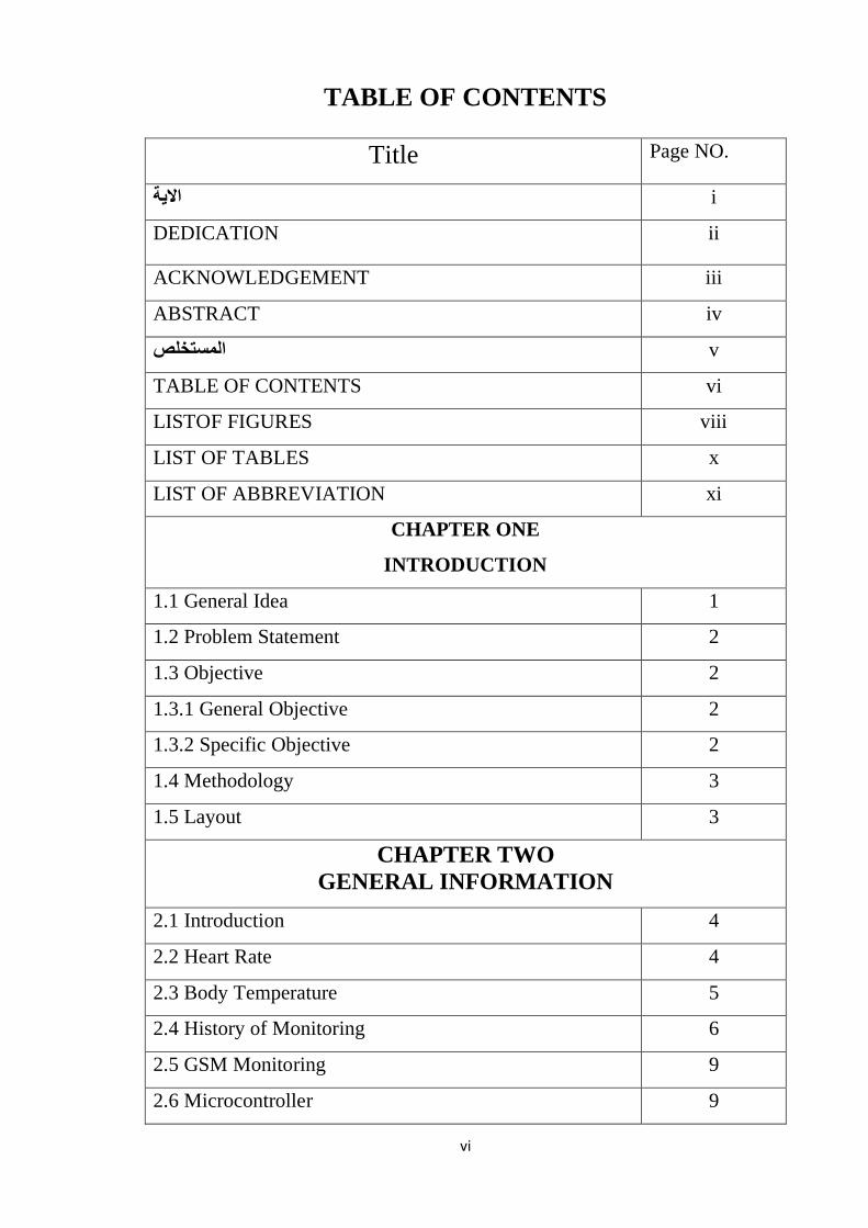
TABLE OF CONTENTS
Title Page NO.
i االية
DEDICATION ii
ACKNOWLEDGEMENT iii
ABSTRACT iv
v المستخلص
TABLE OF CONTENTS vi
LISTOF FIGURES viii
LIST OF TABLES x
LIST OF ABBREVIATION xi
CHAPTER ONE
INTRODUCTION
1.1 General Idea 1
1.2 Problem Statement 2
1.3 Objective 2
1.3.1 General Objective 2
1.3.2 Specific Objective 2
1.4 Methodology 3
1.5 Layout 3
CHAPTER TWO
GENERAL INFORMATION
2.1 Introduction 4
2.2 Heart Rate 4
2.3 Body Temperature 5
2.4 History of Monitoring 6
2.5 GSM Monitoring 9
2.6 Microcontroller 9

vii
2.7 Sensors 11
2.7.1 Classification of sensors 11
2.7.2 Different types of sensors 12
2.8 Literature Review 13
CHAPTER THREE
MODELING AND CIRCUIT COMPONENTS
3.1 Introduction 14
3.2 Hardware Requirement 14
3.2.1 Arduino Uno 15
3.2.2 GSM module (SIM900A) 16
3.2.3 IC LM35 temperature sensor 17
3.2.4 Heart beat sensor 19
3.2.5 LCD display 20
3.2.6 Connecting wires 22
3.3 Flow Chart 23
CHAPTER FOUR
SIMULATION AND PRACTICE
4.1 Introduction 24
4.2 Simulation 24
4.3 System Implementation 29
4.4 Operation 32
CHAPTER FIVE
CONCLUSION AND RECOMMANDATION
5.1 Conclusion 33
5.2 Recommendation 33
REFERENCES 34
APPENDIX 35

viii
LIST OF FIGURES
Figure No. Title Page NO.
2.1 Intensive-care unit in 1960s and 1970s 6
2.2 ECG screen 8
2.3 Different types of sensors 12
3.1 Block diagram of the system 14
3.2 Arduino Uno 16
3.3 GSM (Sim900A) 16
3.4 Interface Arduino with GSM (sim900A) 17
3.5 LM35 temperature sensor 18
3.6 Interfacing Arduino with LM35 18
3.7 Heartbeat sensor 19
3.8 Interfacing Arduino with Heartbeat sensor 20
3.9 #2*16 LCD display 21
3.10 Interfacing Arduino with LCD display 21
3.11 Jumping wires 22
3.12 Flow chart of the system 23
4.1 The Proteus Interface 25
4.2 Proteus File Menu 26
4.3 Proteus Default Template Select 26
4.4 Proteus Design Sheet 27
4.5 Component Mode & Pick from Libraries 27
4.6 LM35 Selection 28
4.7 Component Selection 28
4.8 Simulation of The System 29
4.9 Arduino configured with pulse sensor 30
4.10 LM35 interface with Arduino 30
4.11 Arduino configured with GSM 31

ix
4.12 LCD connection 31
4.13 Circuit result 32
4.14 Result in monitor’s phone (SMS) 32

x
LIST OF TABLES
Table No. Title Page No.
2.1 Body temperature chart for children 5
2.2 Body temperature chart for adults 6
3.1 The connection between Arduino UNO’s pin and
GSM (SIM900A) pins
17
3.2 The connection between Arduino UNO’s pin and
LM35 pins
18
3.3 The connection between Arduino UNO’s pin and
Pulse sensor’s pins
20
3.4 The connection between Arduino UNO’s pin and
LCD display pins
22

xi
LIST OF ABBREVIATION
LCD Liquid crystal display
GSM Global system for mobile communications
SMS Short message service
CRT Cathode – ray tube
ECG Electric cardio graph
ICU Intensive care unit
IDE Integrated development environment
USB Unique selling proposition
LED Light emitting diode
BPM Beat per minute
GPR Ground- penetrating radar
TEMP Temperature
IOT Internet of things
ASCII American Standard Code for Information Interchange

1
CHAPTER ONE
INTRODUCTION
1.1 General Idea
Cardiovascular disease is one of the main causes of death in many countries
and thus it accounts for the over 15 million deaths worldwide. In addition,
several million people are disabled by cardiovascular disease. The delay
between the first symptom of any cardiac ailment and the call for medical
assistance has a large variation among different patients and can have fatal
consequences. One critical inference drawn from epidemiological data is that
deployment of resources for early detection and treatment of heart disease has
a higher potential of reducing fatality associated with cardiac disease than
improved care after hospitalization. Hence new strategies are needed in order
to reduce time before treatment. Monitoring of patients is one possible solution.
Also, the trend towards an independent lifestyle has also increased the demand
for personalized non-hospital-based care. Cardiovascular disease has shown
that heart beat rate plays a key role in the risk of heart attack. Heart disease
such as heart attack, coronary heart disease, congestive heart failure, and
congenital heart disease is the leading cause of death for men and women in
many countries. Most of the time, heart disease problems harm the elderly
person. Very frequently, they live with their own and no one is willing to
monitor them for 24 hours a day. In this proposed device, the heart beat and
temperature of patients are measured by using sensors LM35 and heart beat
sensor which is suitable for wireless transmission using SMS messages through
GSM modem. Arduino device is used for temporary storage of the data used
for transmission. For a patient who is already diagnosed with fatal heart disease,
their heart rate condition has to be monitored continuously. This project
proposes and focuses on the design of the heartbeat monitor that is able to
monitor the heart beat rate condition of patient continuously. This signal is

2
processed using the Arduino to determine the heart beat rate and body
temperature per minute. Then, it sends short message service (SMS) alert to
the mobile phone of medical experts or patient's family members, or their
relatives about the condition of the patient and abnormal details via SMS. Thus,
doctors can monitor and diagnose the patient's condition continuously and
could suggest earlier precaution for the patients themselves. This will also alert
the family members to quickly attend to the patient [1].
1.2 Problem Statement
As we know having someone to watch a critically ill person is very
expensive and take a lot of manpower, these valuable resources can be used.
Also patient monitoring devices usually exist in hospitals delivering a
complexity in sequential testing through the day. The patient with heart
problem facing a challenge living normal life because of the fear from heart
attack that can cause death and high cost is one of the problems of continuous
monitoring through wireless device.
1.3 Objectives
The objectives are divided into two subjects
1.3.1 General objective
To develop a cheap prototype of a system that can monitor heart beats and
body temperature of the patient at home and send the data remotely through a
GSM module to the monitor.
1.3.2 Specific objectives
❖ Design and implement a pulse heartbeat detector.
❖ Interface the LM35 temperature sensor.
❖ Design and implement a wireless communication circuit between the
patient and physician.
❖ Simulate the circuit using proteus ISIS.
❖ Test and calibrate the circuit.

3
1.4 Methodology
The methodology starts by collecting information about the heart rate and
temperature signals and how to deal with them, then the way to design and
implement a circuit capable of detecting signals and best technology GSM to
transmit the signals in SMS in text format. A simulation to the circuit is done
to ensure that the design succeeds, then an implementation to the circuit was
done with a test and calibration.
1.5 Layout
Chapter one includes the general idea introduction about the heart beat
monitor system, and stating the problems and its objective and then
methodology of the project. chapter two is a brief detail about the heart rate,
body temperature, history of monitoring, GSM monitoring and past studies
(literature review). While chapter three the modeling and circuit
components, contains the hardware components and the flow chart of the
system. Then chapter four this chapter explains the operation of the project,
and shows the simulation. Finally, chapter five which contains the
conclusion and the recommendation.

4
CHAPTER TWO
GENERAL INFORMATION
2.1 Introduction
Patient Monitoring System is a process in which a doctor can constantly
supervise more than one person, in excess of one parameter at a time in a remote
area [2]. Advancement in medical technologies have made rapid changes in e-
health care system. An innovative and effective e-health monitor model with
wireless technology can be a great help for the people of developing countries.
The technology provides assistance physicians to better diagnose and treat
patients not physically presence on spot as sometimes it’s crucial to provide
remedy or treat patients who are unluckily away from well treatment. In modern
era advanced medical technology effectively contributing in our personal lives.
This assists on improving and saving countless lives all around the world.
Medical technology is a broad field where innovation plays a crucial role in
sustaining health [3].
2.2 Heart Rate
The number of heartbeats per unit of time, usually measured per minutes.
The heart rate is based on the number of contractions of the ventricles. The
heart rate may be too fast (tachycardia) or too slow (bradycardia). The pulse is
a bulge of an artery from waves of the blood that course through the blood
vessels each time the heart beats. The pulse is often taken on the wrist to
estimate the heart rate. Heart rate is the speed of the heartbeats measured by
the number of the contraction of the heart per minute (bpm the heart rate can
vary according to the body's physical needs, including the need to absorb
oxygen and extra carbon dioxide. It is usually equal or close to the pulse
measured at peripheral point. Activities that provide change include physical
exercise, sleep, anxiety, stress, illness, and ingestion include physical exercise,
sleep, anxiety, stress, illness and ingestion of drugs. Many texts cite the normal
resting adult human heart rate as ranging from 60_ 100 bpm. Tachycardia is a

5
fast heart rate, defined as above 100 bpm at rest, Bradycardia is a slow heart
rate, defined as below 60 bpm at rest. The normal resting adult heart rate is
probably closer to a range between 50 during sleep a slow heartbeat with rates
around 40_50 bpm is common and is considered normal. When the heart is not
beating in a regular pattern, this is referred to as an arrhythmia. Abnormalities
of heart rate sometimes indicate disease [4].
2.3 Body Temperature
Body temperature is also a common indication of body condition. Normal
human body temperature is (98.6 ° F ± 0.7°F) and it differs activity of the
person as well as place of measurement. When a person is excessively hot then
the blood vessels in human skin inflate to transfer the excess heat to human skin
surface. And because of this reason, the person starts sweating. Then the sweat
evaporates and this process supports to cool human body. When a person is
too cold, human blood vessels contracted so the blood flow in human skin gets
reduced to preserve temperature of body. As a result, he/she starts shivering
and it is an instinctive, rapid abbreviation of the muscles.[2]
Table2.1: Body temperature chart for children
Body temperature chart for children
Celsius Fahrenheit
Hypothermia < 35.0° < 95.0°
Normal 35.8° – 37.5° 96.4° – 99.5°
Hyperthermia (low-grade fever) > 38.0° > 100.4°
Hyperpyrexia (high fever) > 40.0° > 104.0°

6
Table2.2: Body temperature chart for adults
Body temperature chart for adults
Celsius Fahrenheit
Hypothermia < 35.0° < 95.0°
Normal 36.5° – 37.5° 97.7° – 99.5°
Hyperthermia (low-grade fever) > 38.3° > 100.9°
Hyperpyrexia (high fever) > 41.5° > 106.7°
2.4 History of Monitoring
To meet the increasing demands for more acute and intensive care required
by patients with complex disorders, new organizational units—the ICUs—were
established in hospitals beginning in the 1950s. The earliest units were simply
postoperative recovery rooms used for prolonged stays after open-heart
surgery. Intensive-care units proliferated rapidly during the late 1960s and
1970s.
Figure 2.1: Intensive-care unit in 1960s and 1970s

7
The types of units include burn, coronary, general surgery, open-heart
surgery, pediatric, neonatal, respiratory, and multipurpose medical-surgical
units. [5]
Analog-computer technology was widely available, as were oscilloscopes,
electronic devices used to depict changes in electrical potential on a cathode-
ray tube (CRT) screen. These devices were soon used in specialized cardiac-
catheterization laboratories, and they rapidly found their way to the bedside.
Treatment for serious cardiac arrhythmias (rhythm disturbances) and cardiac
arrest (abrupt cessation of heartbeat)—major causes of death after myocardial
infarctions—became possible. As a result, there was a need to monitor the
ECGs of patients who had suffered heart attacks so that these episodes could
be noticed and treated immediately. In 1963, Day reported that treatment of
post myocardial-infarction patients in a coronary-care unit reduced mortality
by 60 percent. As a consequence, coronary-care units—with ECG monitors—
proliferated. The addition of online blood-pressure monitoring quickly
followed. Pressure transducers, already used in the cardiac-catheterization
laboratory, were easily adapted to the monitors in the ICU. With the advent of
more automated instruments, the ICU nurse could spend less time manually
measuring the traditional vital signs and more time observing and caring for the
critically ill patient. Simultaneously, a new trend emerged; some nurses moved
away from the bedside to a central console where they could monitor the ECG
and other vital-sign reports from many patients. Maloney (1968) pointed out
that this was an inappropriate use of technology when it deprived the patient of
adequate personal attention at the bedside. He also suggested that having the
nurse record vital signs every few hours was “only to assure regular nurse–
patient contact” (Maloney, 1968, p. 606). [5]
Teams from several cities in the United States introduced computers for
physiological monitoring into the ICU, beginning with Shubin and Weil (1966)
in Los Angeles and then Warner and colleagues (1968) in Salt Lake City. Each

8
of these teams developed its application on a mainframe computer system,
which required a large computer room and special staff to keep the system
operational 24 hours per day. The computers used by these developers cost over
$200,000 each in 1965 dollars! Other researchers were attacking more specific
challenges in patient monitoring. For example, Cox and associates (1972) in St.
Louis developed algorithms to analyze the ECG for heart rhythm disturbances
in real-time. The arrhythmia-monitoring system, which was installed in the
coronary-care unit of Barnes Hospital in1969, ran on a relatively inexpensive
microcomputer. Systems with database functions, report-generation systems,
and some decision-making capabilities are usually called computer-based
patient monitors.[5]
Today, systems with database functions, report generation systems, and some
decision-making capabilities are called computer- based patient monitors,
while the basic signal conversion and storage is built into monitors and
considered “patient monitoring”.[5]
Figure2.2: ECG screen

9
2.5 GSM Monitoring
GSM based system using microcontroller and LM35 sensor which is low-
cost and use-friendly. Here, a heartbeat sensor is used to detect the heart rate
and an LM35 sensor to sense the body temperature. These signals are processed
by a PIC microcontroller. Then an SMS alert will be sent to the medical expert
by using a GSM module. Thus, doctors can monitor the health condition of a
patient continuously from a remote place and can suggest the patient about
taking an immediate remedy. As a result, we can save many lives by providing
them a quick service using this system.
2.6 Microcontroller
The term microcontroller or microcomputer is used to describe a system
that includes a minimum of a microprocessor, program memory, data memory,
and input–output (I/O). Some microcontroller systems include additional
components, such as timers, counters, analog-to-digital (A/D) converters, and
so on. Thus, a microcontroller system can be anything from a large computer
having hard disks, floppy disks, and printers to a single-chip embedded
controller. Microcontrollers are dedicated to one task and run one specific
program. The program is stored in ROM (read-only memory) and generally
does not change.
Microcontrollers are divided into categories according to their memory,
architecture, bits and instruction sets as follow
➢ Bits:
❖ 8 bits microcontroller executes logic & arithmetic operations. Examples
of 8 bits micro controller is Intel 8031/8051.
❖ 16 bits microcontroller executes with greater accuracy and performance
in contrast to 8-bit. Example of 16-bit microcontroller is Intel 8096.

10
❖ 32 bits microcontroller is employed mainly in automatically controlled
appliances such as office machines, implantable medical appliances, etc.
It requires 32-bit instructions to carry out any logical or arithmetic
function.
➢ Memory:
❖ External Memory Microcontroller – When an embedded structure is built
with a microcontroller which does not comprise of all the functioning
blocks existing on a chip it is named as external memory microcontroller.
For illustration- 8031 microcontroller does not have program memory on
the chip.
❖ Embedded Memory Microcontroller – When an embedded structure is
built with a microcontroller which comprise of all the functioning blocks
existing on a chip it is named as embedded memory microcontroller. For
illustration- 8051 microcontroller has all program & data memory,
counters & timers, interrupts, I/O ports and therefore its embedded
memory microcontroller.
➢ Instruction Set:
❖ CISC- CISC means complex instruction set computer, it allows the user
to apply 1 instruction as an alternative to many simple instructions.
❖ RISC- RISC means Reduced Instruction Set Computers. RISC reduces
the operation time by shortening the clock cycle per instruction.
➢ Memory Architecture:
❖ Harvard Memory Architecture Microcontroller.
❖ Princeton Memory Architecture Microcontroller.

11
2.7 Sensors
Sensor can be defined as an input device which provides an output (signal)
with respect to a specific physical quantity (input). The term “input device” in
the definition of a Sensor means that it is part of a bigger system which provides
input to a main control system (like a Processor or a Microcontroller). Sensor
can also be defined as device that converts signals from one energy domain to
electrical domain
2.7.1 Classification of Sensors
There are several classifications of sensors. In the first classification of the
sensors, they are divided in to Active and Passive. Active Sensors are those
which require an external excitation signal or a power signal. Passive Sensors,
on the other hand, do not require any external power signal and directly
generates output response.
The other type of classification is based on the means of detection used in
the sensor. Some of the means of detection are Electric, Biological, Chemical,
Radioactive etc.
The next classification is based on conversion phenomenon i.e. the input
and the output. Some of the common conversion phenomena are Photoelectric,
Thermoelectric, Electrochemical, Electromagnetic, etc.
The final classification of the sensors is Analog and Digital Sensors. Analog
Sensors produce an analog output i.e. a continuous output signal with respect
to the quantity being measured. Digital Sensors, in contrast to Analog Sensors,
work with discrete or digital data. The data in digital sensors, which is used for
conversion and transmission, is digital in nature.

12
2.7.2 Different Types of Sensors
The following is a list of different types of sensors that are commonly used
in various applications. All these sensors are used for measuring one of the
physical properties like Temperature, Resistance, Capacitance, Conduction,
Heat Transfer etc.
❖ Temperature Sensor
❖ Proximity Sensor
❖ Accelerometer
❖ IR Sensor (Infrared Sensor)
❖ Pressure Sensor
❖ Light Sensor
❖ Ultrasonic Sensor
❖ Smoke, Gas and Alcohol Sensor
❖ Touch Sensor
❖ Color Sensor
❖ Humidity Sensor
❖ Tilt Sensor
❖ Flow and Level Sensor
Figure2.3: Different types of sensors

13
2.8 Literature Review
This paper proposes a system to monitor the patient’s conditions by
monitoring the body temperature and pulse rate. The system consists of a pulse
rate monitoring software and a wearable device that can measure a subject’s
temperature and pulse rate only by using a fingertip. The device is able to record
the measurement data and interface to PC via Arduino microcontroller. The
recorded data can be viewed as a historical file or can be archived for further
analysis. This work also describes the preliminary experimental results of the
selected sensors to show the usefulness of the sensors for the proposed patient
monitoring system.[6]
An advanced technology has been created for patient monitoring those who
are suffered from heart diseases & physical disorder. Therefore, heart rate
sensor and temperature sensor are used for patient monitoring. Sensors gives
accurate output therefore it rules out the use of traditional medical instruments
such as thermometer and other devices. For continuously sending message
from patient’s location to medical advisory GSM modem used. This module
provides relief to medical advisory for patient monitoring and also to patients
for freedom of movement.[7]

14
CHAPTER THREE
MODELLING AND CIRCUIT COMPONENTS
3.1 Introduction
The main objective is to design such type of device which is used for
continuous monitoring of patients. There will be few sensors like temperature
sensor, pulse sensor to detect patient’s temperature and heart rate. For
implementing this system sensors are needed, Arduino UNO and a power
source. The sensors dedicate the patient’s temperature and pulse rate then
transfer the data to the Arduino then to the LCD display and doctor’s phone
number through the GSM modem. GSM modem is used to make the device
wearable. The patient can move from one place to another with the device and
this will not cause the doctor any problem to monitor.[8]
Figure 3.1: Block diagram of the system
3.2 Hardware Requirement
This system hardware requirements are as follows:

15
3.2.1 Arduino Uno
Arduino is an open-source platform used for building electronics projects.
Arduino consists of both a physical programmable circuit board (often referred
to as a microcontroller) and a piece of software, or IDE (Integrated
Development Environment) that runs on our computer, used to write and
upload computer code to the physical board. The Arduino platform has become
quite popular with people just starting out with electronics, and for good reason.
Unlike most previous programmable circuit boards, the Arduino does not need
a separate piece of hardware (called a programmer) in order to load new code
onto the board – we can simply use a USB cable. Additionally, the Arduino
IDE uses a simplified version of C++, making it easier to learn to program.
Finally, Arduino provides a standard form factor that breaks out the functions
of the micro-controller into a more accessible package. The Arduino is a
microcontroller board based on the ATmega8. It has 14 digital -input/output
pins (of which 6 can be used as PWM outputs), 6 analog inputs, a16 MHz
ceramic resonator, a USB connection, a power jack, an ICSP header, and a reset
button. It contains everything needed to support the microcontroller; simply
connect it to a computer with a USB cable or power it with an AC-to-DC
adapter or battery to get started.
"Uno" means one in Italian and is named to mark the upcoming release of
Arduino 1.0. The Uno and version 1.0 will be the reference versions of Arduino,
moving forward. The Uno is the latest in a series of USB Arduino boards, and
the reference model for the Arduino platform.[8]

16
Figure 3.2: Arduino UNO
3.2.2 GSM module (SIM900A)
We are using GSM (Global System for Mobile Communication) module
SIM900A. SIM900A is in control for communicating between microcontroller
unit and mobile station. SIM900A is a complete dual-band GSM module in a
SMT (Surface Mount Technology) type which is beneficial for small
dimensions and cost-effective solutions. With a tiny configuration of 24mm
×24mm×3mm and low power consumption, SIM900A can fit almost all space
requirements especially for slim and compact demand design.[3]
Figure 3.3: GSM (SIM900A)
We interface GSM (SIM900A) with the Arduino by implementing the
following connection
17
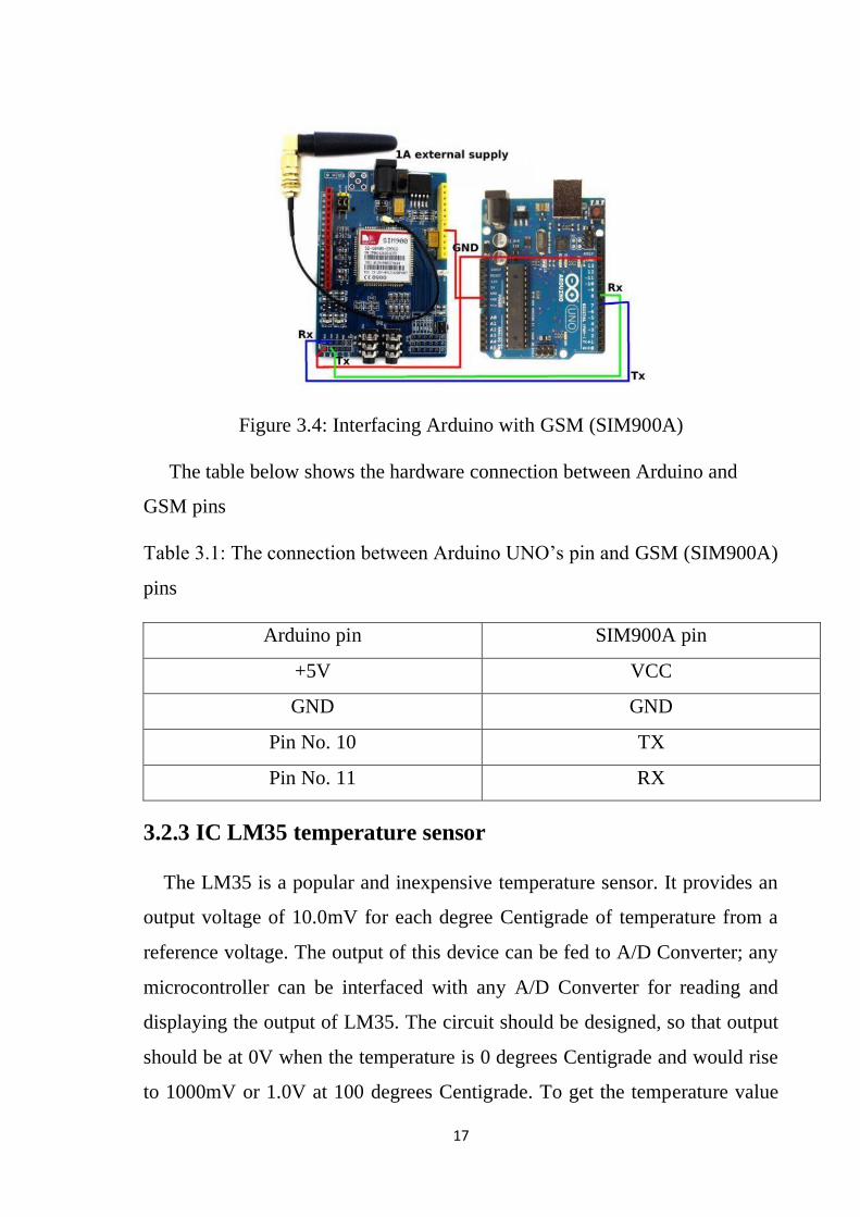
Figure 3.4: Interfacing Arduino with GSM (SIM900A)
The table below shows the hardware connection between Arduino and
GSM pins
Table 3.1: The connection between Arduino UNO’s pin and GSM (SIM900A)
pins
Arduino pin SIM900A pin
+5V VCC
GND GND
Pin No. 10 TX
Pin No. 11 RX
3.2.3 IC LM35 temperature sensor
The LM35 is a popular and inexpensive temperature sensor. It provides an
output voltage of 10.0mV for each degree Centigrade of temperature from a
reference voltage. The output of this device can be fed to A/D Converter; any
microcontroller can be interfaced with any A/D Converter for reading and
displaying the output of LM35. The circuit should be designed, so that output
should be at 0V when the temperature is 0 degrees Centigrade and would rise
to 1000mV or 1.0V at 100 degrees Centigrade. To get the temperature value

18
accurately, output voltage must be multiplied with 100. For example, if we read
0.50V that would be 50 degrees Centigrade.[8]
Figure 3.5: LM35 temperature sensor
We interfaceLM35 with the Arduino by implementing the following
connection
Figure 3.6: Interfacing Arduino with LM35
The table below shows the hardware connection between Arduino and
LM35 pins
Table 3.2: The connection between Arduino UNO’s pin and LM35 pins
Arduino pin LM35 pin
+5V VCC
GND GND
A0 OUTPUT

19
3.2.4 Heartbeat sensor
A Heartbeat sensor is a monitoring device that allows one to measure his or
her heart rate in real time or record the heart rate for later study. It provides a
simple way to study the heart function. This sensor monitors the flow of blood
through the finger and is designed to give digital output of the heartbeat when
a finger is placed on it. When the sensor is working, the beat LED flashes in
unison with each heartbeat. This digital output can be connected to the
microcontroller directly to measure the Beats per Minute (BPM) rate. It works
on the principle of light modulation by blood flow through finger at each pulse.
The Pulse Sensor is a well-designed plug and-play heart-rate sensor for
Arduino. It also includes an open-source monitoring app that graphs your pulse
in real time.[2]
Figure 3.7: Heartbeat sensor
We interface GSM (SIM900A) with the Arduino by implementing the
following connection

20
Figure 3.8: Interfacing Arduino with heartbeat sensor
The table below shows the hardware connection between Arduino and
heartbeat sensor pins
Table 3.3: The connection between Arduino UNO’s pin and Pulse sensor’s
pins
Arduino pin Pulse sensor pin
+5V VCC
GND GND
A1 OUTPUT
3.2.5 LCD display
Unit liquid crystal display (LCD) modules that display characters such as
text and numbers are the cheapest and simplest to use of all LCDs. They can
be purchased in various Sizes, which are measured by the number of rows and
columns of characters they can display. Any LCD with an HD44780-or
KS0066-compatible interface is compatible with Arduino. A 16x2 LCD
display is very basic electronic module and is very commonly used in various
devices and circuits. These modules are preferred over seven segments and
other multi segment LEDs because they are economical, easily programmable,
has no limitation of displaying special and even custom characters (unlike in
seven segments), animations and so on. A 16x2 LCD means it can display 16

21
characters per line and there are 2 such lines. In this LCD each character is
displayed in 5x7 pixel matrix. This LCD has two registers, namely, Command
and Data. The command register stores the command instructions given to the
LCD. A command is an instruction given to LCD to do a predefined task like
initializing it, clearing its screen, setting the cursor position, controlling display
etc. The data register stores the data to be displayed on the LCD. The data is
the ASCII value of the character to be displayed on the LCD.[8]
Figure 3.9: 2*16 LCD display
We interface GSM (SIM900A) with the Arduino by implementing the
following connection
Figure 3.10: Interfacing Arduino with LCD display
22
The table below shows the hardware connection between Arduino and
LCD pins
Table 3.4: The connection between Arduino UNO’s pin and LCD display pins
Arduino UNO pin 2*16 LCD display
+5V VCC
GND VSS
GND VEE
GND RW
Pin No.9 RS
Pin No.8 E (Enable)
Pin No.7 D4
Pin No.6 D5
Pin No.5 D6
Pin No.4 D7
+5V LED +
GND LED -
3.2.6 Connecting wires
A Wire is a single usually cylindrical, flexible strand or rod of metal. Wires
are used to bear mechanical loads or electric and telecommunication signals.
Wire is formed by drawing the metal through a hole in a die or draw plate.[3]
Figure 3.11: Jumping wires

23
3.3 Flow Chart
A flowchart is a picture of the separate steps of a process in sequential order.
It is a generic tool that can be adapted for a wide variety of purposes, and can
be used to describe various processes
Figure 3.12: Flow chart of the system

24
CHAPTER FOUR
SIMULATION AND PRACTICE
4.1 Introduction
There will be few sensors like temperature sensor pulse sensor to detect
patient’s temperature and heart rate. For this we will need sensors, Arduino uno
and a power source. After taking the reading from the patient, the data will be
sent to the database through GSM module. All data along with patient’s, would
be displayed in the LCD. Both the patient and the doctor mobile application
will show the patient’s, state use this system. GSM modem is used to. The
patient can move from one place to another with the device and this will not
cause the doctor any problem to monitor. And the system is simulated in
proteus to make sure the circuit is working.
4.2 Simulation
The Proteus Design Suite is a Windows application for schematic capture,
simulation, and PCB (printed circuit board) layout design. It can be purchased
in many configurations, depending on the size of designs being produced and
the requirements for microcontroller simulation. All PCB Design products
include an autoroute and basic mixed mode Spice simulation capabilities. The
proteus contain
❖ ISIS is the software used to draw schematics and simulate the circuits in
real time. The simulation allows human access during run time, thus
providing real time simulation.
❖ ARES is used for PCB designing. It has the feature of viewing output in
3D view of the designed PCB along with components.
❖ The designer can also develop 2D drawings for the product.

25
Figure 4.1 the proteus interface
ISIS has wide range of components in its library. It has sources, signal
generators, measurement and analysis tools like oscilloscope, voltmeter,
ammeter etc., probes for real time monitoring of the parameters of the circuit,
switches, displays, loads like motors and lamps, discrete components like
resistors, capacitors, inductors, transformers, digital and analog Integrated
circuits, semi-conductor switches, relays, microcontrollers, processors, sensors
etc.
ARES offers PCB designing up to 14 inner layers, with surface mount and
through hole packages. It is embedded with the foot prints of different category
of components like ICs, transistors, headers, connectors and other discrete
components. It offers Auto routing and manual routing options to the PCB
Designer. The schematic drawn in the ISIS can be directly transferred ARES.
Starting New Design:

26
Step 1: Open ISIS software and select New design in File menu
Figure4.2 Proteus File Menu
Step 2: A dialogue box appears to save the current design. However, we are
creating a new design file so you can click Yes or No depending on the content
of the present file. Then a Pop-Up appears asking to select the template. It is
similar to selecting the paper size while printing. For now, select default or
according to the layout size of the circuit.
Figure4.3 Proteus Default Template Select

27
Step 3: An untitled design sheet will be opened, save it according to your wish,
it is better to create a new folder for every layout as it generates other files
supporting your design. However, it is not mandatory.
Figure4.4 Proteus Design Sheet
Step 4: To Select components, Click on the component mode button.
Step 5: Click on Pick from Libraries. It shows the categories of components
available and a search option to enter the part name.
Figure4.5 Component Mode & Pick from Libraries

28
Step 6: Select the components from categories or type the part name in
Keywords text box.
Figure4.6 LM35 Selection
Step 7: The selected components will appear in the devices list. Select the
component and place it in the design sheet by left-click.
Figure4.7 Component Selection
After Place all the required components and route the wires i.e., make
connections. Double click on the component to edit the properties of the
components and click on Ok.

29
Step 8: After connecting the circuit, click on the play button to run the
simulation.
Figure4.8: Simulation of the system
4.3 System Implementation
Since the pulse sensor is simply a plug and play sensor it does not require
much calculation after the data is received. The pulse sensor has three pins as
well. One pin is for the signal coming from the sensed data and the other two
pins are 5volts and Ground.

30
.
Figure 4.9: Arduino configured with pulse sensor
The LM35 temperature sensor has three pins, the first pin is connected with
the ground, the second pin is connected with the output pin in the Arduino
board., which basically gives the temperature result. The last pin is connected
with the 5volt pin in the Arduino. LM35Temperature requires One Wire and
LM35Temperature libraries in the Arduino library folder as well.
Figure 4.10: LM35 interface with Arduino
The GSM modem, SIM900A used in our project is first configured with the
Arduino so that it is able to send data over the internet connectivity. A GSM
modem works like any other typical mobile phone. Since our GSM SIM900A

31
also comes with GPRS enable it has the criterion to provide inter connectivity.
We have inserted a sim card activated with internet connectivity in the GSM
modem. GSM modem sends data over the internet connection to a database
created by us. The database is stored in a webserver which has a particular
address. When the GSM modem is put together with the Arduino in the Arduino
IDE software, the address of that particular webserver is mentioned there so
that the data can be transmitted to exactly the webserver we want it to. The
ground pin is connected with the ground. Pin coming from Arduino. The
Arduino and GSM modem need to be supplied power which can be given by
either connecting those to batteries or using adapters.
Figure 4.11: Arduino configured with GSM
And we connect the LCD to the Arduino as shown inTable3.1
Figure 4.12: LCD connection

32
4.4 Operation
After connecting the circuit, with the patient the vital signals have been
detected by the sensors and then the data has been sent to specified phone
number (the monitor’s number) and shown in LCD display.
Figure 4.13: Circuit result
The figures (4.13) and (4.14) showing the result of the system of heartbeat
and body temperature.
Figure 4.14: Result in monitor’s phone (SMS)

33
CHAPTER FIVE
CONCLUSION AND RECOMMENDATIONS
5.1 Conclusion
The system was implemented also the simulation was done all according to
the theoretical concept of the problem which includes the heart most common
problems and body temperature, the hospitals monitoring routines and the
history of monitoring, the microcontroller and the sensors which the system
was based on, all briefly. To implement the system a heartbeat (pulse) sensor,
temperature sensor (lm35) and Arduino Uno were used, first the simulation was
done by using proteus program then the system which detect body temperature
as an analog signal to the Arduino analog to digital converter, and then the data
is transmitted via GSM to the monitor’s phone was designed and tested. The
results of the system weren’t accurate due to a noise occurred in the sensors.
The cost of the system was satisfying and approximately 10 times cheaper
compared to the cost of the specialized monitor devices.
5.2 Recommendation
➢ More accurate results can be detected by using the original pulse sensor
from www.pulsesensor.com for better quality with less noise.
➢ IOT platform can be used to view and store the data for more
flexibility.

34
REFERENCES
[1] Uroaroh S.U, Oranugo C.O. (2015. August). “Nnamdi azikwe university,
Awka, Nigeria” “heart beat monitoring and alert system using GSM
technology”,
[2] Pratiksha W. Digarse, Sanjaykumar L.Patil, Arduino UNO and GSM Based
Wireless Health Monitoring System for Patients, Dept. of Instrumentation And
Control College of Engineering, Pune
[3] Anika Tasniem, Nura Jamil ,Tabassum Khan, Development of Application
based Health Monitoring System using GSM module .
[4] Haslton, JR; Solomon, IC; Motekaitis, AM; Kaufman, MP (September
1992).”Pronchomotor vagal preganglionic cell bodies in the dog: an anatomic
and functional study”. Journal of applied physiology. 73(3):1122-9. PMID
1400025.
[5] REED M.GARDNER AND M.MICHAEL SHABOT, Patient-Monitoring
Systems.
[6] Azara hazwanie azizulkarim “Design and development of patient
monitoring system” (2017 IOP Conf. Ser.: Mater. Sci. Eng. 226 012094.
[7] Miss. Supriya D. Gawade, Miss. Sayali Y. Jadhav, (2015. April). “GSM
Based Heart Rate and Temperature Monitoring System” International Journal
of Engineering Research & Technology (IJERT) ISSN: 2278-0181
[8] Ashutosh Kumar Ray, Debojit Mondal, Debojit Mondal, GSM Based
Patient Monitoring System Using Biomedical Sensors, DEPARTMENT OF
APPLIED ELECTRONICS & INSTRUMENTATION ENGINEERING,RCC
INSTITUTE OF INFORMATION TECHNOLOGY, CANAL SOUTH
ROAD, BELIAGHATA, KOLKATA –700015, May 2018

35
APPENDIX
System Code
#include <LiquidCrystal.h>
#include<SoftwareSerial.h>
void Send_an_sms(void);
int HR = 0;
SoftwareSerial gsm(12, 13); //RX, TX
int oldA = 0;
int oldC;
unsigned long T;
unsigned long oldT;
unsigned long Dur;
double HR1;
double temp;
const int rs = 9, en = 8, d4 = 7, d5 = 6, d6 = 5, d7 = 4;
LiquidCrystal lcd(rs, en, d4, d5, d6, d7);
void setup()
{
Serial.begin(9600);
gsm.begin(9600);
lcd.begin(16, 2);
lcd.setCursor(0, 0);lcd.print("Heart Rate: ");

36
lcd.setCursor(0, 1);lcd.print("Temperature: ");
}
void loop()
{
int B = analogRead(0);
temp = (B * 5) / 10.23;
int A = analogRead(1);
int C = (A > 355);
int C2 = ((double)C - (double)oldC)>0.5;
if(C2 == 1)
{
T = millis();
Dur = T - oldT;
HR1 = 60000/Dur;
if(HR1 > 50 && HR1 < 150) HR = HR1;
Serial.println(HR);
oldT = T;
}
double Rem1 = millis() % 500; // Control Sending duration
//Serial.print("Rem= "); Serial.println((int)Rem);
if((int)Rem1 < 25)
{

37
lcd.setCursor(13, 0); lcd.print(" ");
lcd.setCursor(13, 0);lcd.print(HR);
lcd.setCursor(15, 1); lcd.print(" ");
lcd.setCursor(13, 1); lcd.print((int) temp);
}
double Rem = millis() % 2000; // Control Sending duration
//Serial.print("Rem= "); Serial.println((int)Rem);
if((int)Rem < 25){
Serial.println("Sending");
Send_an_sms();
Serial.println("Sent");
}
oldA = A;
oldC = C;
delay(50);
}
void Send_an_sms(void)
{
delay(100);
gsm.println ("AT+CMGF=1");
delay(200);

38
gsm.println("AT+CMGS=\"+249117076852\"\r");
delay(200);
gsm.print("Temp = ");
delay(200);
gsm.print(temp);
delay(200);
gsm.print(" Heart Rate = ");
delay(200);
gsm.println(HR);
gsm.println((char)26);//the ASCII code of the (0x1A)
delay(10000);
}