Hard versus Soft Materials as Supports for Metallocene and Post-Metallocene Catalysts
11
Hard versus Soft Materials as Supports for Metallocene and Post-Metallocene Catalysts Corinna Naundorf, Daniela Ferrari, Giovanni Rojas, Gerhard Fink,* Markus Klapper,* Klaus Mu ¨llen Introduction A wide variety of single-site catalysts for the polymerization of ethylene are known to produce polyethylene with defined molecular weight. [1] In addition to traditional metallocenes, the so-called post-metallocenes have proven to be attractive catalysts due to useful properties, such as production of branched polyethylene or copolymerization of polar mono- mers. [2] Among post-metallocenes, zirconium, and titanium complexes bearing phenoxy-imine ligands stand out for high activity toward ethylene polymerization and also for imparting control over molecular weight. [3,4] Both metallocenes and post-metallocenes have to be supported on suitable materials as they produce a dust-like material, which means that reactor fouling could occur in homogeneous polymerization. [5] In addition to silica, [6] organic materials have shown the ability to support metallocenes for further polymerization. [7] We introduced latex particles produced by the miniemulsion polymeriza- tion of styrene and divinylbenzene, with a size of 50– 200 nm, as organic supports. During immobilization of the catalysts, the latex particles agglomerate reversibly to larger secondary catalyst particles due to the presence of the cocatalyst methylaluminoxane (MAO). [8] Fragmentation of the secondary particles is guaranteed by reversible cross- linking between MAO and functional groups, such as polyethylene oxide chains or pyridine groups on the surface of the latex particles. [9–12] Surface functionalization of the latex particles with nucleophilic groups allows immobili- zation of the active catalyst. The fragmentation of the catalyst particles is one important aspect during the polymerization of olefins via a supported catalyst. Various methods of studying the polymerization behavior of supported catalysts are available. By measuring the monomer consumption, e.g., a model for the fragmentation process in slurry polymerizations can be developed. Such models are complemented with video microscopy studies Full Paper C. Naundorf, G. Rojas, M. Klapper, K. Mu ¨llen Max-Planck-Institute for Polymer Research, Ackermannweg 10, 55128 Mainz, Germany E-mail: [email protected] D. Ferrari, G. Fink Max-Planck-Institute for Coal Research, Kaiser-Wilhelm-Platz 1, 45470 Mu ¨lheim, Germany E-mail: fi[email protected] The influence of organic supports on the polymerization behavior of post-metallocene catalysts is studied and compared with similarly supported titanium and zirconium metallo- cenes. The effects of the immobilization, activation, and polymerization process were studied by video microscopy, laser confocal fluorescence microscopy, SEM, and TEM. A model for the polymerization process for a catalyst supported on latex particles was developed from the results obtained. Organic supports based on latex particles are easily adjustable for different catalysts due to the ver- satile functionalization of the surfaces and can be applied to different types of olefin polymerization catalysts. They can be considered as an alternative to SiO 2 or MgCl 2 supports. 456 Macromol. React. Eng. 2009, 3, 456–466 ß 2009 WILEY-VCH Verlag GmbH & Co. KGaA, Weinheim DOI: 10.1002/mren.200900026
-
Upload
independent -
Category
Documents
-
view
2 -
download
0
Transcript of Hard versus Soft Materials as Supports for Metallocene and Post-Metallocene Catalysts

Full Paper
456
Hard versus Soft Materials as Supports forMetallocene and Post-Metallocene Catalysts
Corinna Naundorf, Daniela Ferrari, Giovanni Rojas, Gerhard Fink,*Markus Klapper,* Klaus Mullen
The influence of organic supports on the polymerization behavior of post-metallocenecatalysts is studied and compared with similarly supported titanium and zirconium metallo-cenes. The effects of the immobilization, activation, and polymerization process were studiedby videomicroscopy, laser confocal fluorescencemicroscopy,SEM, and TEM. A model for the polymerization process for acatalyst supported on latex particleswas developed from theresults obtained. Organic supports based on latex particlesare easily adjustable for different catalysts due to the ver-satile functionalization of the surfaces and can be applied todifferent types of olefin polymerization catalysts. They canbe considered as an alternative to SiO2 or MgCl2 supports.
Introduction
Awide variety of single-site catalysts for the polymerization
of ethyleneareknowntoproducepolyethylenewithdefined
molecular weight.[1]In addition to traditional metallocenes,
the so-called post-metallocenes have proven to be attractive
catalysts due to useful properties, such as production of
branched polyethylene or copolymerization of polar mono-
mers.[2] Among post-metallocenes, zirconium, and titanium
complexesbearingphenoxy-imine ligandsstandoutforhigh
activity toward ethylene polymerization and also for
imparting control over molecular weight.[3,4]
Both metallocenes and post-metallocenes have to be
supported on suitablematerials as they produce a dust-like
C. Naundorf, G. Rojas, M. Klapper, K. MullenMax-Planck-Institute for Polymer Research, Ackermannweg 10,55128 Mainz, GermanyE-mail: [email protected]. Ferrari, G. FinkMax-Planck-Institute for Coal Research, Kaiser-Wilhelm-Platz 1,45470 Mulheim, GermanyE-mail: [email protected]
Macromol. React. Eng. 2009, 3, 456–466
� 2009 WILEY-VCH Verlag GmbH & Co. KGaA, Weinheim
material, which means that reactor fouling could occur in
homogeneous polymerization.[5] In addition to silica,[6]
organic materials have shown the ability to support
metallocenes for further polymerization.[7] We introduced
latex particles produced by the miniemulsion polymeriza-
tion of styrene and divinylbenzene, with a size of 50–
200nm, as organic supports. During immobilization of the
catalysts, the latex particles agglomerate reversibly to
larger secondarycatalystparticlesdueto thepresenceof the
cocatalystmethylaluminoxane (MAO).[8] Fragmentation of
the secondary particles is guaranteed by reversible cross-
linking between MAO and functional groups, such as
polyethyleneoxide chainsorpyridinegroupson the surface
of the latex particles.[9–12] Surface functionalization of the
latex particles with nucleophilic groups allows immobili-
zation of the active catalyst. The fragmentation of the
catalyst particles is one important aspect during the
polymerization of olefins via a supported catalyst. Various
methods of studying the polymerization behavior of
supported catalysts are available. By measuring the
monomer consumption, e.g., amodel for the fragmentation
process in slurry polymerizations can be developed. Such
models are complemented with video microscopy studies
DOI: 10.1002/mren.200900026

Hard versus Soft Materials as Supports for Metallocene . . .
performed in gas phase, where the growing catalyst
particles reveal additional information about the polymer-
ization and fragmentation of single particles.[13–16] A fast
method toelucidate the fragmentationand thedistribution
of the support in a product particle is laser scanning
confocal fluorescence microscopy (LSCFM).[17] As latex
particles are a rather new class of supporting material,
the polymerization in the presence of the resulting
supported catalysts is not completely understood. This
was our major driving force for intensive studies on
exemplarily selected supported metallocenes and post-
metallocenes. Thekineticsof thepolymerizationusing such
catalyst systemswas studied in a batch reactor and also by
video microscopy on the single particle level. Detailed SEM
and LSCFM studies clarified the fragmentation process of
the supports. Comparison of the results describedherewith
previously studied silica supported catalysts led to a
completely new model, which follows a different poly-
merizationcoursewhile inthepresenceoforganic supports.
Experimental Part
General Procedure and Materials
All air and water sensitive reactions were performed under dry
argon atmosphere using standard Schlenk techniques or a dry
nitrogenglovebox system.Dried solvents for supporting procedure
and polymerizations were purchased from Acros (toluene) or
Aldrich (heptane) and used without further purification. Styrene
(Aldrich), divinylbenzene (Fluka), and 4-vinyl pyridine (Aldrich)
weredriedoverCaH2anddistilledunder reducedpressure. Lutensol
AT50 (C16C18 fatty alcohol ethoxylates-EO50) was donated from
BASF AG and used without further purification. Hexadecane
(Merck-Schuchardt), a,a0-azodiiso-butyramidinedihydrochloride
(Fluka), cetyltrimethylammoniumbromide (Sigma) were used
without further purification. Deionized water was used for all
miniemulsion polymerizations. The cocatalyst,MAOwas obtained
from Albemarle as 1.2M toluene solution. DriedMAO (DMAO) was
obtained by the evaporation of the solvent and the resulting solids
were used without further purification. Ethylene (BASF AG,
Ludwigshafen) was purified by passing through columns of BASF
R3-15 deoxygenation catalyst and 4 A molecular sieves. For video
microscopy and kinetic polymerizations, ethylene was purified
additionally over a NaAlEt4 column followed by a 4 A molecular
sievescolumn.Purificationof isobutanewasachievedwithOxisorb
andHydrosorb gas purification systems. Triisobutylaluminum (1M
in hexane) and Tri-n-octylaluminum (25wt.-% in hexane) were
obtained from Aldrich and used without further purification.
Preparation of the PEO-pyridine Functionalized Latex
Particles, Stained with Dye
Lutensol AT50 (400mg, 0.16mmol, 0.15mol-%, 3.5wt.-%) and
cetyltrimethylammoniumbromide (22mg, 0.06mmol) were dis-
solved in distilled water (100mL) at 40 8C and stirred for 30min.
Styrene (5 g, 48.0mmol, 47mol-%), 4-vinylpyridine (5 g, 47.3mmol,
Macromol. React. Eng. 2009, 3, 456–466
� 2009 WILEY-VCH Verlag GmbH & Co. KGaA, Weinheim
46mol-%), divinylbenzene (0.91 g, 7.0mmol, 6mol-%), and hex-
adecane (0.42 g, 1.86mmol) ashydrophobweremixedandadded to
the water/emulsifier mixture at room temperature. The solution
was stirred for 30min and then sonicated with a Branson Sonifier
450W 70% power under ice cooling for 7min to form a
miniemulsion. The miniemulsion was degassed with argon for
20min and then heated to 70 8C. The initiator for radical
polymerization a,a0-azodiiso-butyramidinedihydrochloride (210mg,
0.77mmol) was dissolved in 10mL dist. water, degassed for 20min
and added to theminiemulsion. After 12h themixturewas filtered
and purified by forced dialysis with at least 300mL of water and
then frozen and lyophilized.
Supporting Procedure for Catalysts 1 and 2
(Systems A and B)
The latex-supportwasdried for12 hat 70 8C invacuo. Latex support
(300mg)wasmixedwithDMAO (120mg) and suspended in toluene
(5mL).Todispersethe latexparticlesthesuspensionwasplaced inan
ultrasonic bath for 20min and stirred for an additional 10min.
The catalyst (0.03mmol)was dissolved in toluene (5mL) and the
catalyst solution (2mL) added to the latex particle–cocatalyst
mixture at 0 8C. The mixture was stirred and allowed to warm to
room temperature. The suspensionwas filtered through a glass frit
under nitrogen to remove the solvent. The resulting cakewas dried
in vacuumand transferred into a glovebox. The cakewasmortared
and the resulting powder sieved through analytical sieves with
pore sizes of 60 and40mm.The fractionbetween40 and60mmwas
used for videomicroscopyand the fraction smaller than40mmwas
used for slurry polymerization. The calculated support loading
was estimated to be 29mmol metal g�1 het cat. The aluminum to
metal ratio was estimated to be 170:1.
Supporting Procedure for Catalyst 3 (System C)
The latex supportwasdried for 12 hat 70 8C in vacuo. Latex support
(300mg) was mixed with 3mL of MAO (1.5M, 10wt.-% in toluene)
and an additional 5mL of toluene was added. To disperse the latex
particles thesuspensionwasplaced inanultrasonicbath for20min
and stirred for an additional 10min.
The catalyst (0.032mmol) was dissolved in 3mL of MAO (1.5M,
10wt.-% in toluene) and the catalyst solution (2.1mL) added to the
latex particle–cocatalyst mixture. The mixture was stirred for 1h
and then filtered over a glass frit under nitrogen to remove the
solvent. The resulting cake was dried in vacuum und transferred
into theglovebox. The cakewasmortaredand the resultingpowder
sieved through analytical sieves with pore sizes of 60 and 40mm.
The fraction between 40 and 60mmwas used for videomicroscopy
and the fraction smaller than 40mm was used for slurry
polymerization. The calculated support loading was estimated to
be 30mmol metal g�1 het cat. The aluminum to metal ratio was
estimated to be 340:1.
Polymerization Under High Ethylene Pressure
In a typical ethylene polymerization, the stainless steel reactor
equipped with a propeller-like stirrer was charged with isobutane
www.mre-journal.de 457

C. Naundorf, D. Ferrari, G. Rojas, G. Fink, M. Klapper, K. Mullen
458
(400mL), tri-n-octylaluminum (2mL, 0.95mmol) ortriisobutylalu-
minum (5mL, 5mmol), and poly(propylene glycol)-block-poly-
(ethylene glycol)-block-poly(propylene glycol) (PPG-b-PEG-b-PPG)
(1mg) in toluene (1mL) in case of catalyst (1). The reactor was
heated to the desired polymerization temperature under stirring
(400 rpm) using a thermostat. An ethylene pressure of 40bar was
applied. The catalyst was injected into the reactor under argon
through a pressure lock. After 60min the polymerization was
stoppedby the releaseof ethyleneand isobutane. Thepolyethylene
product was stirred in acidic methanol (400mL), filtered, stirred
again in methanol (400mL), filtered again, and dried in a vacuum
oven at 75 8C under reduced pressure.
Video Microscopy
A small 50mL volume reactor with a borsilicat window in the top
was evacuated for 4 h at 80 8C and transferred into a glovebox. A
silver plate serving as catalyst holder was prepared with catalyst
particles. After reconnection to the gas/vacuum line the reactor
was heated to 55 8C. Simultaneously with picture recording, the
polymerization was started by the addition of monomer to the
reactor. Pictures were recorded every 10 s over a period of 180min.
The polymerization was stopped by release of the monomer. The
recorded pictures were analyzed by Analysis five.
Slurry Polymerization
The slurrypolymerization at lowethylenepressurewas carried out
in heptane slurry in a 250mL glass autoclave equipped with a
variable speed stirrer (1 400 rpm) under constant pressure (1, 2, or
4 bar). 130mL of anhydrous heptane was mixed with the desired
amount of scavenger (trioctylaluminum or triisobutylaluminum)
and added to the reactor. The solution was thermostated and
saturated with monomer up to the desired ethylene pressure. The
heterogeneous catalyst system was injected to the reactor as a
suspension in heptane with argon pressure. The consumption of
monomer gas was registered by mass flow meters. The polymer-
ization was stopped by releasing the monomer and quenched by
the addition ofmethanol. The resulting polymerwaswashedwith
methanol/HCl and puremethanol, filtered and dried at 75 8C under
reduced pressure.
Scheme 1. (1) bis[N-(3-t-butylsalicylidene) cycloheptylaminato]titanium (IV) dichloride, (2) bis[N-(5-methoxy-3-t-butylsalicyli-dene)-2-methylcyclohexylaminato] zirconium (IV) dichloride, and(3) dimethylsilyl-bis-[2-methylbenzindyl] zirconium (IV) dichloride.
Characterization of Polyethylene
Polymer melting points (Tm) were determined on a differential
scanning calorimeter (DSC) using a heating rate of 10 8C �min�1 in
the temperature range of 20–200 8C. The heating cycle was
performed twice, but only the results of the second scan were
reported.
Gel permeation chromatography (GPC) of polyethylene from
catalyst 1 was performed on a Waters 150-C gel permeation
chromatograph at 145 8C using three TSKgel columns (two sets of
TSKgelGMHHR-H(S)HTandTSKgelGMH6-HTL)with refractive index
detection and calibration versus narrow polystyrene standards.
Polyethylene from catalysts 2 and 3 was performed.
Macromol. React. Eng. 2009, 3, 456–466
� 2009 WILEY-VCH Verlag GmbH & Co. KGaA, Weinheim
Scanning electron micrographs were obtained by using an LEO
Zeiss. The polyethylene was applied on a graphite tape.
Results and Discussions
Immobilization of the Catalysts
To study the olefin polymerization in the presence of post-
metallocenes immobilized on latex particles, titanium (1)
anda zirconium (2) catalyst bearingphenoxy-imine ligands
(FI-catalysts, see Scheme 1) were chosen as examples.
MetalloceneMe2Si(2-MeBenzInd)2ZrCl2 (3) was selected for
comparisonwith the two FI-catalysts because it has shown
excellent properties in ethylene polymerization when
supported on functionalized latex particles. All catalysts
are activatedwithmethylaluminoxane (MAO),which is the
most common cocatalyst formetallocenes and FI-catalysts.
The chosen catalysts were supported on latex particles
functionalized with PEO-chains and pyridine-groups on
their surfaces. These organic supports have already shown
suitability for two selected catalysts. Metallocene 3,
supported on latex particles, produces polyethylene with
high activity, productivity, and narrow molecular weight
distributions.[10,18] The FI-titanium catalyst 1 also exhibits
excellent properties for producing ultrahigh molecular
weight polyethylene (UHMWPE) with narrow molecular
weight distribution.[19] The particles were synthesized by
the miniemulsion polymerization of styrene, 4-vinylpyr-
idine, divinylbenzene, and a styryl-functionalized perylene
monoimide derivative (see Scheme 2). PEO-ethoxy fatty
alcohol was used as an emulsifier to stabilize the
miniemulsion. Alongwith the pyridine groups, PEO-chains
also helped to anchor the activated catalyst. The latex
particle size (primary particles) was about 150nm, deter-
mined by dynamic light scattering. During the immobiliza-
tion process of the catalysts, the primary particles
agglomerate reversibly to a secondary catalyst particle.
During ethylene polymerization, these secondary catalyst
particles fragmented down to primary latex particles,
DOI: 10.1002/mren.200900026

Hard versus Soft Materials as Supports for Metallocene . . .
Scheme 2. Synthesis of the organic support containing a fluorescent perylene dye.
which were then spread homogeneously within the
resulting polyethylene particle.[16,17]
For immobilization on theorganic supports, the catalysts
were dissolved in toluene and pre-activated with the
addition of MAO. The organic supports were mixed with
MAO and the pre-activated catalysts were added. The
immobilization procedure of catalysts 1 and 2was slightly
different from the immobilization of catalyst 3, as the FI-
catalysts decomposed during the pre-activationwithMAO.
This may be attributed to the decomposition of the FI-
catalysts by the presence of free trimethylaluminum (TMA)
in MAO.[20] Therefore, the content of free TMA in the
cocatalyst was reduced by co-evaporation of TMA and
toluene. DMAO with a lower content of free TMA
redissolved in toluene was then used as an activator for
the FI-catalysts 1 and 2. For immobilization of the FI-
catalysts, a mixture of dried PEO-pyridine-functionalized
latex particles and DMAO was redispersed in toluene,
followedby the addition of catalysts 1 or 2 to themixture of
the carrier and activator. The obtained catalyst systems A
andBwerefiltrated throughaglass frit.A clearandcolorless
filtrate was obtained for both catalysts, indicating that
most of the catalyst, which had originally shownan orange
or yellow color in solution, was immobilized on the carrier.
Table 1. Elemental analysis for the catalyst systems A–C.
Catalyst System Calculated Calculated Observeda) result Observeda)
wt.-% of
met
wt.-% of
Al
wt.-% of
met
wt.-%
Al
A [Ti] 0.14 15.1 0.12 (86%) 14.9 (98
B [Zr] 0.26 13.3 0.23 (88) 12.8 (96
C [Zr] 0.27 27.5 0.16 (60) 24.0 (87
a)Elemental analysis was performed by ICP-OES.
Macromol. React. Eng. 2009, 3, 456–466
� 2009 WILEY-VCH Verlag GmbH & Co. KGaA, Weinheim
The remaining filter cake—the supported
catalyst—was ready to use after drying
under vacuum and controlled crushing.
Immobilization of metallocene 3 (cat-
alyst system C) was performed by pre-
activation of 3with MAO and addition to
a mixture of carrier and MAO. Upon
filtration, the yellow filtrate indicated
that not all the catalyst was immobilized.
Since leaching of the catalyst results in
reactor fouling and dust formation, all
three catalyst systemsA–Cwereanalyzed
for their composition to determine
whether complete immobilization had
been achieved. Elemental analysis of
aluminum, titanium, or zirconium
(Table 1) of the resulting catalyst systems
showed that in the case of FI-catalysts 1 and 2 almost all the
catalyst and cocatalyst added to the supporting material
had been immobilized. For catalystA, 98%of the aluminum
added was adsorbed on the latex particles surface, while
86% of the catalyst added to the latex particles was
immobilized. In the case of catalyst 2, FI-zirconiumcatalyst,
nearly all aluminumof theDMAOwas also absorbed on the
organic carrier, while 88% of the catalyst was immobilized.
In contrast, based on the elemental analysis from catalyst 3,
87% of aluminum and only 60% of the added zirconiumwas
immobilized to the carrier.
An explanation for the lower degree of immobilization
for metallocene 3might be an incomplete formation of the
activated cationic catalyst complex. Only the positively
charged species can be immobilized by electrostatic
interaction with the nucleophilic surface of an inorganic
or organic support. Catalyst complexes that exist as neutral
species are not able to be adsorbed on the carrier as they
cannot interact directly with the supports or with the
cocatalyst MAO.[19] For FI-titanium catalysts, it has been
proved by NMR studies that at very low aluminum to
titanium ratios of 50:1, the methylated cationic complex,
which is the active species in ethylene polymerization,was
formed.[21] Thisverifies thatall catalystmoleculesof1and2
result Catalyst loading Al:met-ratio
of mmol metal g�1
het cat
%) 25 220
%) 25 190
%) 17 500
www.mre-journal.de 459

C. Naundorf, D. Ferrari, G. Rojas, G. Fink, M. Klapper, K. Mullen
460
were transformed to cationic complexes at the chosen
aluminum to metal ratio of around 200:1. For catalyst 3,
however, the formation of cationic active species was only
observed at aluminum to zirconium ratios of more than
300:1[22] Therefore, it can be assumed that themetallocene
3 was not completely converted into the cationic species
andnon-activatedmetallocenecomplexeswerefiltratedoff
along with the solvent.
Slurry Polymerization of the Catalysts A, B, and C atHigh Ethylene Pressure (40 bar)
The three different catalyst systemsA, B, and Cwere tested
toward ethylene polymerization at a pressure of 40 bar.
Polymerizations were performed in liquid isobutane in the
presence of a scavenger suitable for the catalysts (Table 2).
For systems A and B trioctylaluminum was chosen as a
scavenger, since previous studies have shown that narrow
molecular weight distributions are obtained using this
scavenger and FI-titanium catalyst.[19] For catalyst C,
triisobutylaluminum was used as scavenger. In polymer-
izations performed using the catalyst system A, a hydro-
philic block copolymer [5mg PPG-b-PEG-b-PPG (Mw ¼ ca.
2 500 gmol�1)] had to be added to the polymerization
medium to avoid static agglomeration of the produced
polyethylene, which would result in reactor fouling.[23]
System C showed an activity of 8 150 kg PE mol�1
Zr h�1 � bar�1 at 75 8C, which was slightly higher than the
activity of the FI-zirconium catalyst, 6 100 kg PE mol�1
Zr h�1 � bar�1 at the same polymerization temperature. At
70 8C the FI-titanium catalyst (1) showed an activity of
1 300 kg PE mol�1 Ti h�1 � bar�1, which was significantly
lower than that of the zirconium catalysts. This is in good
agreement with the results obtained for the correspond-
ing homogeneous polymerizations, which indicates that
both catalysts are influenced in a similar way by the
supportingmaterial.[24] CatalystCproducedpolyethylene
with a weight average molecular weight of
1 250 kg �mol�1 and a molecular weight distribution of
3.2. Catalyst A produced UHMWPEwith a weight average
molecular weight of 4 710 kg �mol�1 and a molecular
Table 2. Polymerization results of the three catalysts.
Catalyst Catalyst
systems
Scavenger TP
mmol -C
1 A [Ti] 1-TOA 70
2 B [Zr] 2-TOA 75
3 C [Zr] 5-TIBA 75
Polymerization conditions: 1 L stainless steel reactor, 400mL isobutan
Macromol. React. Eng. 2009, 3, 456–466
� 2009 WILEY-VCH Verlag GmbH & Co. KGaA, Weinheim
weight distribution of 2.3, which is rather narrow for
supported catalysts. The FI-zirconium catalyst system B
producedUHMWPEwith ahighermolecularweightMw of
5 450 kg �mol�1 and a molecular weight distribution of
more than 30, unusually broad for single-site catalysts.
This phenomenon might be caused by the formation of
different conformations of the FI-zirconium catalyst.[25]
For most catalysts only the lowest level of energy, an
octahedral conformation, is obtained by calculations,
which indicates a single site-catalyst resulting in a
polyethylene with a narrow molecular weight distribu-
tion. However, for a few FI-zirconium catalysts a multi-
modal distribution of the polyethylene is obtained during
homogeneous polymerization.[25] It is assumed that in
these casesmore than one conformationwith aminimum
of energy exists, which results in a multi-site catalyst
system.
Closer insight into the influence of the support and the
typeof catalystonthepolymerizationprocesswasobtained
by studying the overall kinetics[26] in a batch reactor (slurry
polymerization). Single grain kinetics[14,27] were obtained
from gas phase polymerizationsmonitored in situ by video
microscopy. Additional informationwasmade available by
visualizing the morphology of the obtained particles by
SEM.
Kinetic Investigations in Slurry Polymerization
For kinetic investigation, evaluating the activity and
productivity of the supported catalysts, slurry polymeriza-
tions were performed in heptane using catalyst systems A,
B, and C. Ethylene consumption was controlled by a mass
flow-meter. The experiments were run at 50 and 75 8C. Apressureof4 bar (Table3)wasapplied inorder to slowdown
the polymerization process and to obtain accurate data at
the beginning of the polymerization. B showed the highest
polymerization activity [13 000 kg PE mol�1 Zr h�1 �bar�1]
in heptane. Interestingly, the activity was significantly
higher than that at high ethylene pressure in isobutene
(Table26 100 kgPEmol�1Zrh�1 �bar�1. In contrast, catalyst
C showed a similar activity under high (40bar) and low
Activity Mwa) Mn=Mw
a)
kg PE mol�1
met h�1 � bar�1T 103kg �mol�1
1.30 4 710 2.3
6.10 5 450 37
8.15 1 250 3.2
e, 40 bar ethylene pressure.a)Analyzed by GPC (PS-standard).
DOI: 10.1002/mren.200900026
Hard versus Soft Materials as Supports for Metallocene . . .
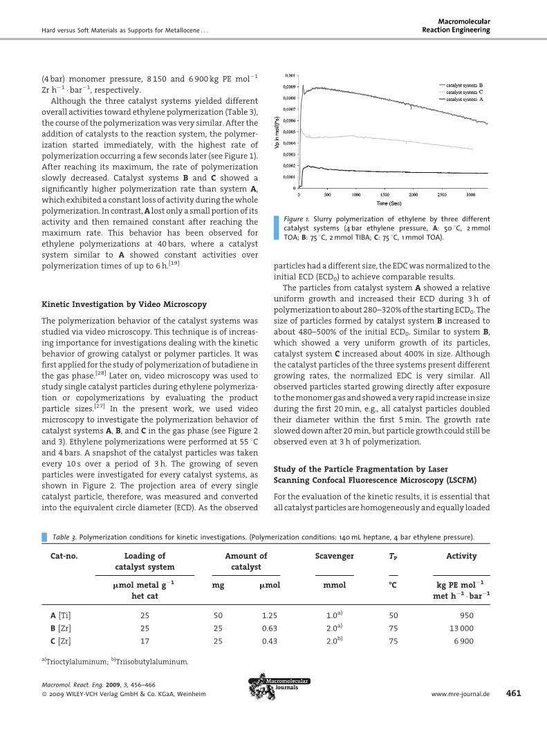
Figure 1. Slurry polymerization of ethylene by three differentcatalyst systems (4 bar ethylene pressure, A: 50 8C, 2 mmolTOA; B: 75 8C, 2 mmol TIBA; C: 75 8C, 1 mmol TOA).
(4 bar) monomer pressure, 8 150 and 6 900 kg PE mol�1
Zr h�1 �bar�1, respectively.
Although the three catalyst systems yielded different
overall activities toward ethylene polymerization (Table 3),
the course of the polymerizationwas very similar. After the
addition of catalysts to the reaction system, the polymer-
ization started immediately, with the highest rate of
polymerization occurring a few seconds later (see Figure 1).
After reaching its maximum, the rate of polymerization
slowly decreased. Catalyst systems B and C showed a
significantly higher polymerization rate than system A,
whichexhibiteda constant lossof activityduring thewhole
polymerization. In contrast,A lost only a small portion of its
activity and then remained constant after reaching the
maximum rate. This behavior has been observed for
ethylene polymerizations at 40 bars, where a catalyst
system similar to A showed constant activities over
polymerization times of up to 6h.[19]
Kinetic Investigation by Video Microscopy
The polymerization behavior of the catalyst systems was
studied via video microscopy. This technique is of increas-
ing importance for investigations dealing with the kinetic
behavior of growing catalyst or polymer particles. It was
first applied for the study of polymerization of butadiene in
the gas phase.[28] Later on, video microscopy was used to
study single catalyst particles during ethylene polymeriza-
tion or copolymerizations by evaluating the product
particle sizes.[27] In the present work, we used video
microscopy to investigate the polymerization behavior of
catalyst systems A, B, and C in the gas phase (see Figure 2
and 3). Ethylene polymerizations were performed at 55 8Cand 4bars. A snapshot of the catalyst particles was taken
every 10 s over a period of 3 h. The growing of seven
particles were investigated for every catalyst systems, as
shown in Figure 2. The projection area of every single
catalyst particle, therefore, was measured and converted
into the equivalent circle diameter (ECD). As the observed
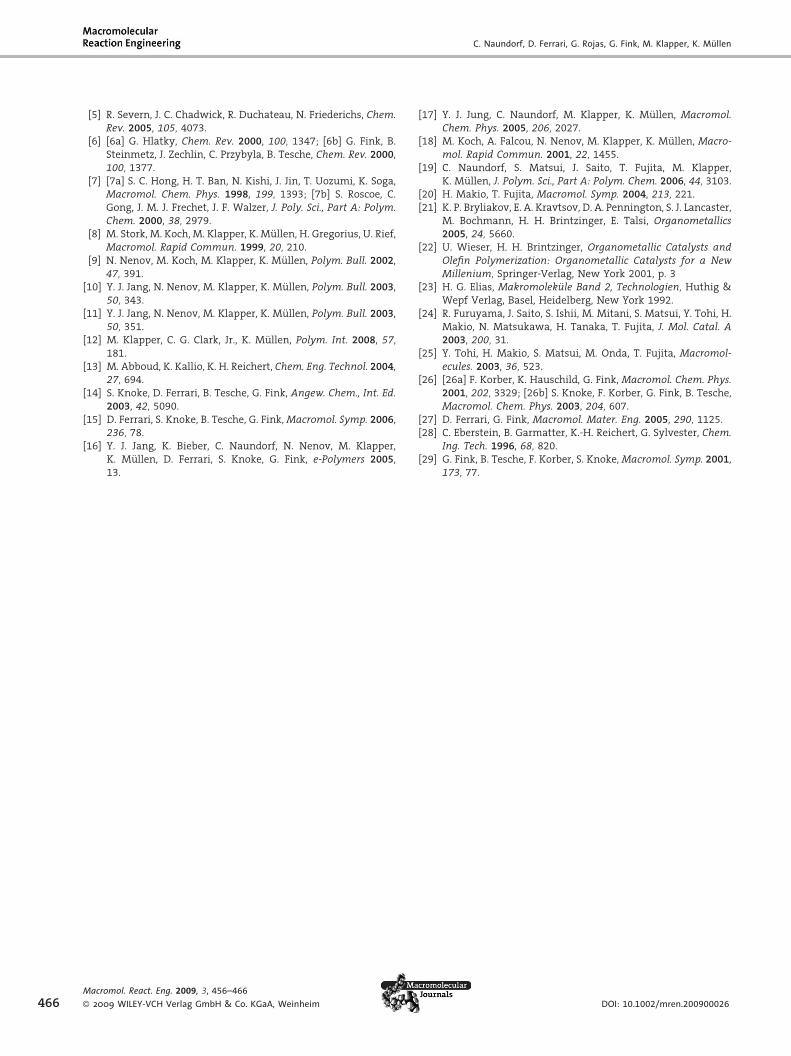
Table 3. Polymerization conditions for kinetic investigations. (Polyme
Cat-no. Loading of
catalyst system
Amount of
catalyst
mmol metal g�1
het cat
mg mm
A [Ti] 25 50 1.2
B [Zr] 25 25 0.6
C [Zr] 17 25 0.4
a)Trioctylaluminum; b)Triisobutylaluminum.
Macromol. React. Eng. 2009, 3, 456–466
� 2009 WILEY-VCH Verlag GmbH & Co. KGaA, Weinheim
particles had adifferent size, the EDCwasnormalized to the
initial ECD (ECD0) to achieve comparable results.
The particles from catalyst system A showed a relative
uniform growth and increased their ECD during 3h of
polymerization toabout280–320%of thestartingECD0. The
size of particles formed by catalyst system B increased to
about 480–500% of the initial ECD0. Similar to system B,
which showed a very uniform growth of its particles,
catalyst system C increased about 400% in size. Although
the catalyst particles of the three systems present different
growing rates, the normalized EDC is very similar. All
observed particles started growing directly after exposure
to themonomergasandshowedaveryrapid increase insize
during the first 20min, e.g., all catalyst particles doubled
their diameter within the first 5min. The growth rate
sloweddownafter 20min, but particle growth could still be
observed even at 3 h of polymerization.
Study of the Particle Fragmentation by LaserScanning Confocal Fluorescence Microscopy (LSCFM)
For the evaluation of the kinetic results, it is essential that
all catalyst particles arehomogeneouslyandequally loaded
rization conditions: 140 mL heptane, 4 bar ethylene pressure).
Scavenger TP Activity
ol mmol -C kg PE mol�1
met h�1 � bar�1
5 1.0a) 50 950
3 2.0a) 75 13 000
3 2.0b) 75 6 900
www.mre-journal.de 461

C. Naundorf, D. Ferrari, G. Rojas, G. Fink, M. Klapper, K. Mullen
Figure 2. Initial catalyst particles system (A) [Ti] and after gasphase polymerization (B) [4 bar ethylene, 55 8C, 30mmol Ti g�1 CatAl:Ti 170:1].
Figure 3. ECD/ECD0 versus time obtained from gas phasepolymerization of ethylene with (a) catalyst A, (b) catalyst B,and (c) catalyst C at 55 8C and 4 bar.
462Macromol. React. Eng. 2009, 3, 456–466
� 2009 WILEY-VCH Verlag GmbH & Co. KGaA, Weinheim
with thepolymerization catalysts. It has tobeexcluded that
the macroscopically observed activity does not result from
only a part of the catalyst. Additionally, it has to be
confirmed that the expected fragmentation process of the
secondary particles is taking place. Both can be easily
visualized by LSCFM.[17] The organic supports, therefore,
were tagged directly during the particle formation via
emulsion polymerization with a fluorescent styryl functio-
nalized perylene monoimide (see Scheme 2).[17] The
particles of all catalyst systems yielded a homogeneous
intense fluorescence before being applied in the polymer-
ization process. After polymerization olefin beads were
obtained showing a very homogeneous distribution of
fluorescent spots (Figure4). Depending on the reaction time
these spots increase in quantity but decrease in size, which
proves that fragmentation of the supports occurs in the
required manner.
The activities obtained for the supported catalyst
systems and the initial studies by LSCM indicate that the
supported systems here studied are suitable for olefin
polymerization. All catalysts show excellent activities
yielding high-molecular polyethylenes.
Comparison of Soft and Hard Materials forSupporting Catalyst
Apart from the different activity and the different relative
growth of the catalyst particles, no significant difference in
the course of the polymerization of the three catalyst
systems could be observed. However, in comparison to
silica-supported catalysts,[6,29] a dramatic difference in the
polymerization process was found. In the slurry and gas
phases, the olefin polymerizations with a silica-supported
catalyst canbedivided into fourdifferentphases. In thepre-
polymerization phase, a first slight polymerization activity
of the supported catalyst can be observed.[14] During this
Figure 4. LSCM saturated images of the middle slice of a productparticle obtained from catalyst A after (a) 5 min and (b) 15 min ofethylene polymerization [magnification of the middle layer(objective, plan Neofluar 10; wavelength, 488 nm; 70% trans-mission; scale bar, 20mm)].
DOI: 10.1002/mren.200900026

Hard versus Soft Materials as Supports for Metallocene . . .
phase, a thin crystalline layer of polyethylene is formed
round the catalyst particle. In the second phase, there is a
dramatic reduction inactivity. This effect is causedbya lack
of monomer inside the particles because the monomer has
to diffuse through the crystalline layer of polyethylene
encapsulating the catalyst particle to reach the inner active
centers (diffusion phase). The monomer reaches the active
centers in the core of the particles slowly to form polymer
inside the bead. The generated polymer imparts hydraulic
forces to the support, fragmenting the catalyst particle
(secondary particle) from outside to inside (fragmentation
phase). More active sites become accessible to the mono-
mer, yielding more centers for ethylene polymerization. A
steady increase in activity is observed until the catalyst
particle is completely fragmented and the catalyst system
reaches a maximum rate of polymerization. In the
following particle expansion phase, the polymer particle
expands, andaslowdecrease in thepolymerization rate can
be observed. This effect originates from the increasing
diffusion ways due to the expanding particle of the
monomers to the active centers. This model of describing
the polymerization in the presence of silica-supported
catalysts is called ‘‘polymer-growth and particle-expan-
sion-model’’.[29]
Unlike silica-supported catalysts, the latex-supported
catalyst reaches a maximum in the polymerization rate
immediately after polymerization begins. No significant
drop in the polymerization activity was found after the
maximum rate was reached, which indicates that no
crystalline layerofpolymerwas formedaround thecatalyst
particle. As shown in Figure 1 for latex-supported catalysts,
the maximum rate of polymerization was observed a few
seconds after polymerization began. This can be attributed
to the fact that there was no diffusion barrier. After the
maximum polymerization rate was reached, the activity
decreased steadily into the followingphase. Thedecrease in
activity couldbeobservedduring thewholepolymerization
time for catalyst systems B and C. For catalyst system A,
which showed the lowest activity, the polymerization rate
remained constant for the rest of the polymerization after a
slight drop in the first minutes. This is in agreement with
the results obtained from polymerizations at high pressure
where a constant activity for catalyst system A was
observed over 6 h. There are two explanations for the
decrease in polymerization activity. One possible explana-
tion is that all active metal centers in the catalyst particle
take part in the polymerization right from the beginning.
The continuous drop in polymerization can then be
explained by the diffusion way of the monomer into the
catalyst particle,whichbecomes longerwith the expansion
of the resulting polymer.
It is obvious that the polymerization behavior of latex-
supported catalysts in slurry polymerization in a batch
reactor, video microscopy, and LSCFM leads to a different
Macromol. React. Eng. 2009, 3, 456–466
� 2009 WILEY-VCH Verlag GmbH & Co. KGaA, Weinheim
mechanism. After the addition of monomer to the reactor,
no initiation phase was found but catalyst particles began
to grow immediately. During polymerization, the growing
rateof theparticles slowlydecreasesbutevenafter60mina
significant polymerization, indicated by the expansion of
the catalyst/polymer particles, was observed.
The different activity of latex- and silica-supported
catalysts at the beginning of the polymerization can be
explained by the different consistence of the carrier
material. Silica is a hard material, which can adsorb the
monomeronly in thepores. Theorganic latexparticles swell
in the polymerization solvent andmonomer is thereby also
absorbed in the carrier material itself. In the case of silica-
supported catalysts, after the small amount of monomer
stored in the pores is consumed, new monomer has to
diffuse into the particle through the crystalline polyethy-
lene layer. The active centers supported on the latex
particles can be fedwithmonomer directly from the carrier
material until new monomer diffuses into the particle.
Another important factor is the composition of the
catalyst particles. While the silica primary particles
agglomerate to a very hard and strong particle, the primary
latex particles build a secondary particle by agglomeration
only through nucleophilic interaction with the cocata-
lyst.[18] Therefore, the catalyst particle based on organic
material consists only of a loose network, which can be
fragmentedmuch easier through the hydraulic force of the
polymer formed inside the catalyst particles. The ability of
the latex particles to swell with monomer and the loose
network of latex particles are the two factors that result in
the very high activity for latex-supported catalysts
immediately after initiation of the polymerization. Since
the organic support is able to swell, presence of monomer
from the beginning of the polymerization is guaranteed
along the whole particle. Polymerization of the polyolefin,
therefore, starts not only on the surface of the secondary
particle but also at the same time in the interior. In contrast
to a porous silica support, the physical cross-linking of the
organic secondary particles is much weaker and the
polyethylene formed during polymerization can break up
the supporting material much more easily. As a result, the
fragmentation can take place throughout the organic
support without an induction period.
Polymer Morphology of the ObtainedPolyolefin Particles
Study of the morphology of the product particles (e.g.,
particle size and surface morphology) gives detailed
information about the polymerization process. Therefore,
polymerizations performed in thevideomicroscopy reactor
in gas phase at different times were developed. The
polymerizations were stopped by releasing the monomer
after the desired polymerization time, and the polymer
www.mre-journal.de 463

C. Naundorf, D. Ferrari, G. Rojas, G. Fink, M. Klapper, K. Mullen
Figure 6. Polyethylene of (a) catalyst A and (b) catalyst C after 15 min of polymerization time.
Figure 5. Polyethylene obtained from (a) catalyst A and (b) catalyst C after 30 s of polymerization time.
464
particles were exposed to air
to deactivate the catalyst.
The surfaces of the obtained
polymer particles were inves-
tigated by SEM.
Figure 5(a) shows an SEM-
imageofapolymer sampleof
catalyst systemAafter30 sof
polymerization. On the left,
nano-sized spherical parti-
cles can be seen. These par-
ticles can be identified as the
primary latex particles that
serve as supporting material
for the catalyst. Due to the
defined spherical shape of
the latex particles, the pro-
duced polyethylene can be
distinguished from the origi-
nal supporting material.
Polyethylene seems to grow
likebubblesoutof thecarrier.
Polyethyleneparticles from
catalyst system C, obtained
after 30 s of polymerization,
differed significantly from
PE-particles of catalyst sys-
tem A. On the surface of the
polymer sample from cata-
lyst C, primary latex particles could also be identified, but
the polyethylene produced was not cauliflower-like
[Figure 5(b)]. Some of the latex particles do not seem to
participate in the polymerization as they are still clearly
visible on the surface of theproduct particle in their original
size and not surrounded by polyethylene. On the PE
particles of both catalyst systems, areas could be found
where no polymer was formed during the first seconds,
while inotherareas thepolymerizationhadalreadystarted.
For both types of supported catalysts, itmight be suggested
that every single latex particle in the secondary particle
can be seen as a mini reactor where initiation of the
polymerizationneededmoreor less time.One reasonmight
bea localdifference in theconcentrationofmetalloceneand
activator or in a different accessibility to the monomer.
Samples after 15min of polymerization also showed
differences in polymer morphology. While the polymer
particles fromcatalyst C [see Figure 6(b)]were replica of the
original secondary catalyst particles, the polymer particles
from catalyst A [see Figure 6(a)] seemed to be an
agglomeration of small single polymer spheres replicating
the shape of the primary particles.
At longer polymerization times, characteristic morphol-
ogy structures were found on the polymer particles of all
catalyst systems. On the surface of polymer samples from
Macromol. React. Eng. 2009, 3, 456–466
� 2009 WILEY-VCH Verlag GmbH & Co. KGaA, Weinheim
catalystBaswell as fromcatalystC, filamentsorfibrilswere
observed. The fibrils on the surface of PE particles were
formedduetoexpansionof thePEparticles. Polymer formed
in the inside led to expansion of the particle. The surface of
the polymer particle could not expand due to minor
polymerproduction, and thepolymer surfacewasstretched
to fibrils (Figure 7).
The formation of polyethylene filaments led to the
suggestion that a high concentration of inter-crystalline
links was formed during polymerization. Another indica-
tion of high concentrations of inter-crystalline links was
found by analyzing the melting temperature of the
produced polyethylene by DSC (Table 4). A marked
difference in the melting temperature of the polyethylene
samples between the first and second heating cycles of the
measurement was observed. For example, in the first
heating cycle of the DSC analysis, PE of catalyst B showed a
melting temperature of 147 8C, while after cooling in the
second heating cycle a Tm of 140 8C was observed. This is a
strong indication for the high concentration of inter-
crystalline links in the nascent PE. After melting of the
polymer sample, cooling, and recrystallization, a normal
concentration of inter-crystalline links was formed and
therefore Tm was significantly lower. The inter-crystalline
linkswereprobably causedbyacombinationof two factors.
DOI: 10.1002/mren.200900026

Hard versus Soft Materials as Supports for Metallocene . . .
Table 4. Melting temperatures of PE-samples from catalyst sys-tems 1–3.
PE from
cat-no
Tm first
heating cycle
Tm second
heating cycle
DTm
-C -C -C
A [Ti] 146 140 6
B [Zr] 147 140 7
C [Zr] 139 135 5
Figure 7. Polyethylene obtained from (a) catalyst A and (b) catalyst C after 60 min of polymerizationtime at high ethylene pressure.
One factorwas ahigh concentration of active centers on the
surface of the supportingmaterial. Thesemight have led to
crystallization of polymer chains surrounded by polyethy-
lene spherolithes. Another factor might have been that the
polymerization rate of ethylene by the catalysts was faster
than the crystallization rate of the produced polyethylene
chains. Therefore, the polymer chains are entangled and
crystallized indifferent spherolites to form inter-crystalline
links.
Conclusion
Only hard inorganic supports such as MgCl2 or SiO2 are
typically applied for supporting metallocene and post-
metallocene catalysts in industrial applications. Although
they are well understood due to their technical relevance,
they still have disadvantages, e.g., pre-polymerization is
sometimes required, incomplete fragmentation occurs
during the polymerization, and an inhomogeneous course
of thepolymerization (e.g., an inductionperiod) is observed.
In this paper, we have reported on the systematic
investigation of latex particles as a rather new class of
soft organic support. Immobilization of different types of
catalysts on the particles was elaborated and their
polymerization behavior compared to silica supported
Macromol. React. Eng. 2009, 3, 456–466
� 2009 WILEY-VCH Verlag GmbH & Co. KGaA, Weinheim
catalysts. It becomes obvious
that the immobilization pro-
cedure and the activation
process have a dramatic
influence on the polymeriza-
tion process. While tradi-
tional metallocenes had to
be pre-activated to result in
good polymerization per-
formance, the FI-catalysts
reacted sensitive to MAO
and decomposed. A detailed
understanding of the poly-
merization process by a sup-
ported catalyst is essential
for improving and enhancing a catalyst system.However, a
comprehensive description of the polymerization process
requires many different methods. While polymerization
experiments in larger reactor systems provide the overall
activity and productivity values, a more detailed look was
necessary to elucidate the processes inside and on the
surface of a single catalyst particle. Video microscopy and
LSCFM were particularly suitable methods to study the
homogeneity of the loading of the supports and the
fragmentation. Opticalmethods such as SEM or TEM reveal
additional information about particle growth, surface
changes, and also inner morphology of the polyolefin
particles obtained. Additionally, organic supports offer the
possibility to optimize each catalyst system simply by
varying the nature of the surface of the organic nanopar-
ticles. In contrast to silica orMgCl2-based supports, organic-
based supports can be synthesized in amuchwider variety
just by altering the type of surfactants, monomers and also
by varying the reaction conditions in the emulsion and
miniemulsion process. The incorporation of pyridine into
the particles drastically improves the activity of the Zr-FI
catalyst.
Acknowledgements: The financial support of Mitsui Chemicals isgratefully acknowledged.
Received: April 24, 2009; Revised: July 10, 2009; DOI: 10.1002/mren.200900026
Keywords: catalysis; catalysts; metallocene; polyolefine; reactionkinetics
[1] W. Kaminsky, Macromol. Chem. Phys. 1996, 197, 3907.[2] L. S. Boffa, B. M. Novak, Chem. Rev. 2000, 100, 1479.[3] S. Matsui, T. Fujita, Catal. Today 2001, 66, 63.[4] H. Makio, N. Kashiwa, T. Fujita, Adv. Synth. Catal. 2002, 344,
477.
www.mre-journal.de 465
C. Naundorf, D. Ferrari, G. Rojas, G. Fink, M. Klapper, K. Mullen
466
[5] R. Severn, J. C. Chadwick, R. Duchateau, N. Friederichs, Chem.Rev. 2005, 105, 4073.
[6] [6a] G. Hlatky, Chem. Rev. 2000, 100, 1347; [6b] G. Fink, B.Steinmetz, J. Zechlin, C. Przybyla, B. Tesche, Chem. Rev. 2000,100, 1377.
[7] [7a] S. C. Hong, H. T. Ban, N. Kishi, J. Jin, T. Uozumi, K. Soga,Macromol. Chem. Phys. 1998, 199, 1393; [7b] S. Roscoe, C.Gong, J. M. J. Frechet, J. F. Walzer, J. Poly. Sci., Part A: Polym.Chem. 2000, 38, 2979.
[8] M. Stork, M. Koch, M. Klapper, K. Mullen, H. Gregorius, U. Rief,Macromol. Rapid Commun. 1999, 20, 210.
[9] N. Nenov, M. Koch, M. Klapper, K. Mullen, Polym. Bull. 2002,47, 391.
[10] Y. J. Jang, N. Nenov, M. Klapper, K. Mullen, Polym. Bull. 2003,50, 343.
[11] Y. J. Jang, N. Nenov, M. Klapper, K. Mullen, Polym. Bull. 2003,50, 351.
[12] M. Klapper, C. G. Clark, Jr., K. Mullen, Polym. Int. 2008, 57,181.
[13] M. Abboud, K. Kallio, K. H. Reichert, Chem. Eng. Technol. 2004,27, 694.
[14] S. Knoke, D. Ferrari, B. Tesche, G. Fink, Angew. Chem., Int. Ed.2003, 42, 5090.
[15] D. Ferrari, S. Knoke, B. Tesche, G. Fink,Macromol. Symp. 2006,236, 78.
[16] Y. J. Jang, K. Bieber, C. Naundorf, N. Nenov, M. Klapper,K. Mullen, D. Ferrari, S. Knoke, G. Fink, e-Polymers 2005,13.
Macromol. React. Eng. 2009, 3, 456–466
� 2009 WILEY-VCH Verlag GmbH & Co. KGaA, Weinheim
[17] Y. J. Jung, C. Naundorf, M. Klapper, K. Mullen, Macromol.Chem. Phys. 2005, 206, 2027.
[18] M. Koch, A. Falcou, N. Nenov, M. Klapper, K. Mullen, Macro-mol. Rapid Commun. 2001, 22, 1455.
[19] C. Naundorf, S. Matsui, J. Saito, T. Fujita, M. Klapper,K. Mullen, J. Polym. Sci., Part A: Polym. Chem. 2006, 44, 3103.
[20] H. Makio, T. Fujita, Macromol. Symp. 2004, 213, 221.[21] K. P. Bryliakov, E. A. Kravtsov, D. A. Pennington, S. J. Lancaster,
M. Bochmann, H. H. Brintzinger, E. Talsi, Organometallics2005, 24, 5660.
[22] U. Wieser, H. H. Brintzinger, Organometallic Catalysts andOlefin Polymerization: Organometallic Catalysts for a NewMillenium, Springer-Verlag, New York 2001, p. 3
[23] H. G. Elias, Makromolekule Band 2, Technologien, Huthig &Wepf Verlag, Basel, Heidelberg, New York 1992.
[24] R. Furuyama, J. Saito, S. Ishii, M. Mitani, S. Matsui, Y. Tohi, H.Makio, N. Matsukawa, H. Tanaka, T. Fujita, J. Mol. Catal. A2003, 200, 31.
[25] Y. Tohi, H. Makio, S. Matsui, M. Onda, T. Fujita, Macromol-ecules. 2003, 36, 523.
[26] [26a] F. Korber, K. Hauschild, G. Fink, Macromol. Chem. Phys.2001, 202, 3329; [26b] S. Knoke, F. Korber, G. Fink, B. Tesche,Macromol. Chem. Phys. 2003, 204, 607.
[27] D. Ferrari, G. Fink, Macromol. Mater. Eng. 2005, 290, 1125.[28] C. Eberstein, B. Garmatter, K.-H. Reichert, G. Sylvester, Chem.
Ing. Tech. 1996, 68, 820.[29] G. Fink, B. Tesche, F. Korber, S. Knoke, Macromol. Symp. 2001,
173, 77.
DOI: 10.1002/mren.200900026