Harbor Freight Manual
12
-
Upload
khangminh22 -
Category
Documents
-
view
4 -
download
0
Transcript of Harbor Freight Manual
Page 2 For technical questions, please call 1-800-444-3353. Item 66839
SAFETy
OpER
ATION
MA
INTEN
AN
cE
SETUp
Table of contentsSafety ......................................................... 2Specifications ............................................. 5Setup .......................................................... 6Operation .................................................... 8
Maintenance .............................................. 10Parts List and Diagram .............................. 11Warranty .................................................... 12
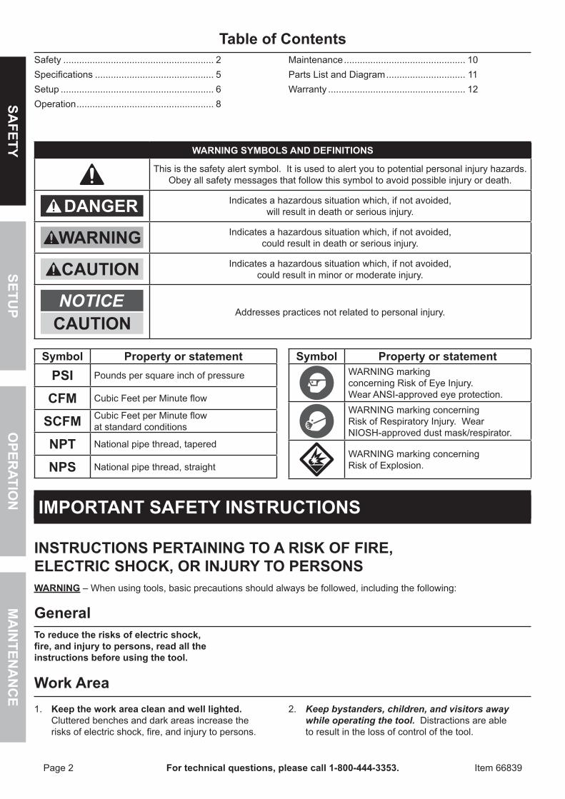
WARNING SyMBOLS AND DEFINITIONS
This is the safety alert symbol. It is used to alert you to potential personal injury hazards. Obey all safety messages that follow this symbol to avoid possible injury or death.
Indicates a hazardous situation which, if not avoided, will result in death or serious injury.
Indicates a hazardous situation which, if not avoided, could result in death or serious injury.
Indicates a hazardous situation which, if not avoided, could result in minor or moderate injury.
Addresses practices not related to personal injury.
Symbol property or statementpSI Pounds per square inch of pressure
cFM Cubic Feet per Minute flow
ScFM Cubic Feet per Minute flow at standard conditions
NpT National pipe thread, tapered
NpS National pipe thread, straight
Symbol property or statementWARNING marking concerning Risk of Eye Injury. Wear ANSI-approved eye protection.WARNING marking concerning Risk of Respiratory Injury. Wear NIOSH-approved dust mask/respirator.
WARNING marking concerning Risk of Explosion.
IMpORTANT SAFETy INSTRUcTIONS
INSTRUcTIONS pERTAINING TO A RISK OF FIRE, ELEcTRIc SHOcK, OR INJURy TO pERSONSWARNING – When using tools, basic precautions should always be followed, including the following:
GeneralTo reduce the risks of electric shock, fire, and injury to persons, read all the instructions before using the tool.
Work Area1. Keep the work area clean and well lighted.
Cluttered benches and dark areas increase the risks of electric shock, fire, and injury to persons.
2. Keep bystanders, children, and visitors away while operating the tool. Distractions are able to result in the loss of control of the tool.
Page 3For technical questions, please call 1-800-444-3353.Item 66839
SAFE
TyO
pER
ATIO
NM
AIN
TEN
AN
cE
SETU
p
personal Safety1. Stay alert. Watch what you are doing and
use common sense when operating the tool. Do not use the tool while tired or under the influence of drugs, alcohol, or medication. A moment of inattention while operating the tool increases the risk of injury to persons.
2. Dress properly. Do not wear loose clothing or jewelry. contain long hair. Keep hair, clothing, and gloves away from moving parts. Loose clothes, jewelry, or long hair increases the risk of injury to persons as a result of being caught in moving parts.
3. Avoid unintentional starting. Be sure the switch is off before connecting to the air supply. Do not carry the tool with your finger on the switch or connect the tool to the air supply with the switch on.
4. Do not overreach. Keep proper footing and balance at all times. Proper footing and balance enables better control of the tool in unexpected situations.
5. Use safety equipment. A dust mask, non-skid safety shoes and a hard hat must be used for the applicable conditions.
6. Always wear eye protection. Wear ANSI-approved safety goggles.
7. Always wear hearing protection when using the tool. Prolonged exposure to high intensity noise is able to cause hearing loss.
Tool Use and care1. Do not force the tool. Use the correct tool for the
application. The correct tool will do the job better and safer at the rate for which the tool is designed.
2. Disconnect the tool from the air source before making any adjustments, changing accessories, or storing the tool. Such preventive safety measures reduce the risk of starting the tool unintentionally. Turn off and detach the air supply, safely discharge any residual air pressure, and release the throttle and/or turn the switch to its off position before leaving the work area.
3. Store the tool when it is idle out of reach of children and other untrained persons. A tool is dangerous in the hands of untrained users.
4. Maintain the tool with care. A properly maintained tool is easier to control.
5. check for misalignment or binding of moving parts, breakage of parts, and any other condition that affects the tool's operation. If damaged, have the tool serviced before using. Many accidents are caused by poorly maintained tools. There is a risk of bursting if the tool is damaged.
6. Use only accessories that are identified by the manufacturer for the specific tool model. Use of an accessory not intended for use with the specific tool model, increases the risk of injury to persons.
Service1. Tool service must be performed only
by qualified repair personnel.2. When servicing a tool, use only identical
replacement parts. Use only authorized parts.
Air Source1. Never connect to an air source that is
capable of exceeding 200 psi. Over pressurizing the tool may cause bursting, abnormal operation, breakage of the tool or serious injury to persons.
Use only clean, dry, regulated compressed air at the rated pressure or within the rated pressure range as marked on the tool. Always verify prior to using the tool that the air source has been adjusted to the rated air pressure or within the rated air-pressure range.
2. Never use oxygen, carbon dioxide, combustible gases or any bottled gas as an air source for the tool. Such gases are capable of explosion and serious injury to persons.
SAVE THESE INSTRUcTIONS.
Page 4 For technical questions, please call 1-800-444-3353. Item 66839
SAFETy
OpER
ATION
MA
INTEN
AN
cE
SETUp
Specific Safety Instructions1. The warnings and precautions discussed in this
manual cannot cover all possible conditions and situations that may occur. It must be understood by the operator that common sense and caution are factors which cannot be built into this product, but must be supplied by the operator.
2. WARNING: Some dust created by power sanding, sawing, grinding, drilling, and other construction activities, contains chemicals known [to the State of California] to cause cancer, birth defects or other reproductive harm. Some examples of these chemicals are: • Lead from lead-based paints • Crystalline silica from bricks and cement or other masonry products • Arsenic and chromium from chemically treated lumber Your risk from these exposures varies, depending on how often you do this type of work. To reduce your exposure to these chemicals: work in a well ventilated area, and work with approved safety equipment, such as those dust masks that are specially designed to filter out microscopic particles. (California Health & Safety Code § 25249.5, et seq.)
3. WARNING: The brass components of this product contain lead, a chemical known to the State of California to cause birth defects (or other reproductive harm). (California Health & Safety Code § 25249.5, et seq.)
4. Do not spray near open flames, pilot lights, stoves, heaters, the air compressor, or any other heat source. Most solvents and coatings are highly flammable, particularly when sprayed. Maintain a distance of at least 25 feet from the air compressor. If possible, locate the air compressor in a separate room.
5. Paints and solvents may be harmful or fatal if swallowed or inhaled. Avoid prolonged skin contact with solvents or paints as they will irritate skin. After any contact, immediately wash off exposed area with hot, soapy water.
6. Attach all accessories properly to the tool before connecting the air supply. A loose accessory may detach or break during operation.
7. Install an in-line shutoff valve to allow immediate control over the air supply in an emergency, even if a hose is ruptured.
8. Air hose fittings may get hot during use. Allow fittings to cool before disconnecting.
9. Coatings can produce eye irritation. When cleaning tools exercise caution when using solvents. They can be forcefully ejected from the tool’s nozzle and air passages. Wear an ANSI-approved dust mask or respirator when working around chemical mist.
10. Do not exceed the maximum pressure. Exceeding the maximum pressure will cause the safety valve to release air to prevent the tank from exceeding its maximum pressure. Exceeding the Tank’s maximum pressure can cause the pressure tank to rupture or explode.
11. During each use, pull the ring on the safety valve to check that it operates freely and relieves air pressure. If the safety valve is stuck, does not operate freely, or does not relieve air pressure, replace the valve.
12. Do not discard or make any alterations to the safety valve. Tampering with, welding or drilling the tank can weaken it.
13. Do not use abrasive or corrosive materials or materials that can cause rust with this tank. It is not designed for those materials. To use them can damage the tank’s internal parts.
14. Industrial applications must follow OSHA requirements.
15. Read all information concerning coating products and cleaning solvents. Chlorinated solvents, such as 1-1-1 Trichloroethane and Methylene Chloride (also known as methyl chloride) can chemically react with aluminum and explode. Many paint sprayers contain aluminum. If you are in doubt about potential chemical reactions, contact the coating or solvent manufacturer.
16. check all seals before connecting the spray tool to the air supply.
17. Make sure that the lid is fully attached to the tank before pressurizing. Do not release the lid while the tank is pressurized.
18. Do not use wrenches, pliers or other tools to tighten paint Tank clamps. Use your hands only. If gasket leaks, clean it or replace it.
SAVE THESE INSTRUcTIONS.
Page 5For technical questions, please call 1-800-444-3353.Item 66839
SAFE
TyO
pER
ATIO
NM
AIN
TEN
AN
cE
SETU
p
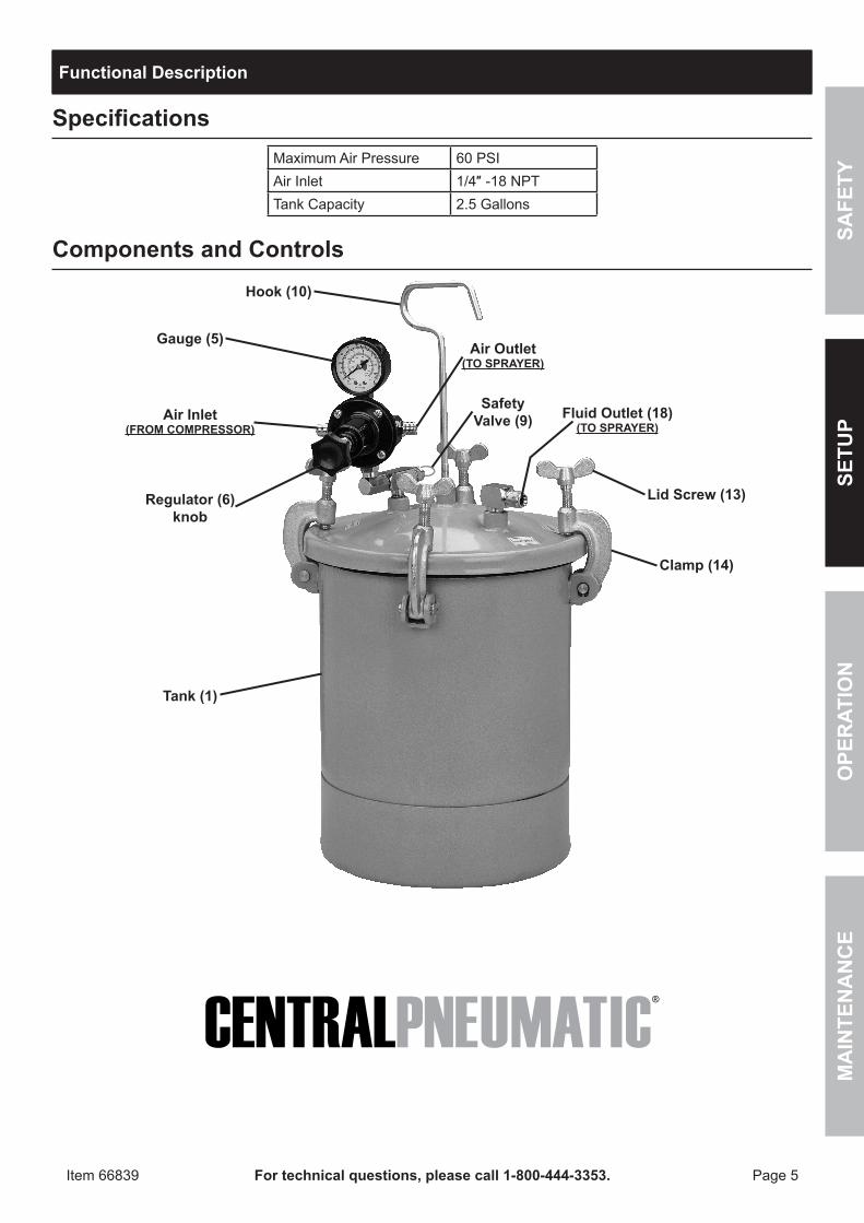
Functional Description
SpecificationsMaximum Air Pressure 60 PSIAir Inlet 1/4″ -18 NPTTank Capacity 2.5 Gallons
components and controls
Safety Valve (9) Fluid Outlet (18)
(TO SpRAyER)
Lid Screw (13)
clamp (14)
Tank (1)
Gauge (5)
Air Inlet (FROM cOMpRESSOR)
Hook (10)
Air Outlet (TO SpRAyER)
Regulator (6) knob
Page 6 For technical questions, please call 1-800-444-3353. Item 66839
SAFETy
OpER
ATION
MA
INTEN
AN
cE
SETUp
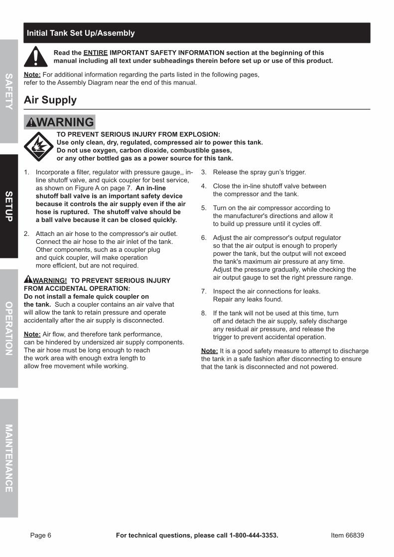
Initial Tank Set Up/Assembly
Read the ENTIRE IMpORTANT SAFETy INFORMATION section at the beginning of this manual including all text under subheadings therein before set up or use of this product.
Note: For additional information regarding the parts listed in the following pages, refer to the Assembly Diagram near the end of this manual.
Air Supply
TO pREVENT SERIOUS INJURy FROM EXpLOSION: Use only clean, dry, regulated, compressed air to power this tank. Do not use oxygen, carbon dioxide, combustible gases, or any other bottled gas as a power source for this tank.
1. Incorporate a filter, regulator with pressure gauge,, in-line shutoff valve, and quick coupler for best service, as shown on Figure A on page 7. An in-line shutoff ball valve is an important safety device because it controls the air supply even if the air hose is ruptured. The shutoff valve should be a ball valve because it can be closed quickly.
2. Attach an air hose to the compressor's air outlet. Connect the air hose to the air inlet of the tank. Other components, such as a coupler plug and quick coupler, will make operation more efficient, but are not required.
WARNING! TO pREVENT SERIOUS INJURy FROM AccIDENTAL OpERATION: Do not install a female quick coupler on the tank. Such a coupler contains an air valve that will allow the tank to retain pressure and operate accidentally after the air supply is disconnected.
Note: Air flow, and therefore tank performance, can be hindered by undersized air supply components. The air hose must be long enough to reach the work area with enough extra length to allow free movement while working.
3. Release the spray gun’s trigger.
4. Close the in-line shutoff valve between the compressor and the tank.
5. Turn on the air compressor according to the manufacturer's directions and allow it to build up pressure until it cycles off.
6. Adjust the air compressor's output regulator so that the air output is enough to properly power the tank, but the output will not exceed the tank's maximum air pressure at any time. Adjust the pressure gradually, while checking the air output gauge to set the right pressure range.
7. Inspect the air connections for leaks. Repair any leaks found.
8. If the tank will not be used at this time, turn off and detach the air supply, safely discharge any residual air pressure, and release the trigger to prevent accidental operation.
Note: It is a good safety measure to attempt to discharge the tank in a safe fashion after disconnecting to ensure that the tank is disconnected and not powered.
Page 7For technical questions, please call 1-800-444-3353.Item 66839
SAFE
TyO
pER
ATIO
NM
AIN
TEN
AN
cE
SETU
p
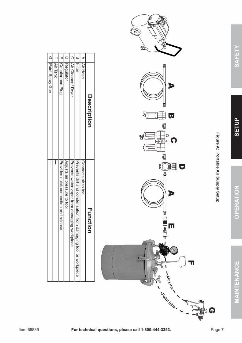
paint Line
Air Line
Description
FunctionA
Air H
oseC
onnects air to toolB
FilterP
revents dirt and condensation from dam
aging tool or workpiece
CA
ir Cleaner / D
ryerP
revents water vapor from
damaging w
orkpieceD
Regulator
Adjusts air pressure to tool
EC
oupler and Plug
Provides quick connection and release
FA
ir Tank—
GP
aint Spray G
un—
AE
AB
C
F
G
D
Figure A: portable A
ir Supply Setup
Page 8 For technical questions, please call 1-800-444-3353. Item 66839
SAFETy
OpER
ATION
MA
INTEN
AN
cE
SETUp
Operating Instructions
Read the ENTIRE IMpORTANT SAFETy INFORMATION section at the beginning of this manual including all text under subheadings therein before set up or use of this product.
Inspect tool before use, looking for damaged, loose, and missing parts. If any problems are found, do not use tool until repaired.
Tool Set Up1. Relieve all air pressure in the Tank (1) by
pulling the ring on the Safety Valve (9) until the pressure bleeds down.
2. Loosen the Lid Screws (13) and swing the Clamps (14) open.
3. Set the Lid (3) aside.
4. Mix and prepare the paint/coating according to the manufacturer’s directions.
5. Strain the paint using a fine mesh screen to keep foreign matter and lumps from clogging the Tank’s passageways.
6. Pour the prepared and strained paint into the Tank.
Note: As an alternative, an entire can of properly thinned and strained paint can be placed inside the tank. This method reduces the need for cleanup. Do not move the tank if using this method to limit spilling.
7. Replace the Lid (3), close the Clamps (14) and Lid Screws (13).
8. Connect the air supply hose to the air inlet fitting on the Tank regulator.
9. Attach the sprayer air hose to the air outlet fitting, which is directly opposite the air inlet fitting.
WARNING! The equipment connected to the Tank or hose outlet must have a higher pressure rating than the regulated air pressure in the Tank.
Workpiece and Work Area Set Up1. Designate a work area that is clean and well-lit.
The work area must not allow access by children or pets to prevent distraction and injury.
2. Route the air hose along a safe route to reach the work area without creating a tripping hazard or exposing the air hose to possible damage. The air hose must be long enough to reach the work area with enough extra length to allow free movement while working.
3. Secure loose workpieces using a vise or clamps (not included) to prevent movement while working.
4. There must not be hazardous objects (such as utility lines or foreign objects) nearby that will present a hazard while working.
Page 9For technical questions, please call 1-800-444-3353.Item 66839
SAFE
TyO
pER
ATIO
NM
AIN
TEN
AN
cE
SETU
p
General Operating Instructions1. Turn ON the air supply to the desired spray gun
pSI, but do not exceed the maximum tank pSI.
2. Adjust the paint pressure by turning the T-handle adjusting screw (on regulator) clockwise to increase pressure and counterclockwise to decrease the pressure.
3. Adjust the atomization air for the spray by using the regulator on the Paint Tank.
4. Operate the spray gun according to the manufacturer’s instructions.
5. clean the paint Tank, paint hose and spray gun as soon as work is finished for the day.
6. If the Paint Tank is not operating properly, refer to Troubleshooting on page 10.
cAUTION! TO pREVENT INJURy: Do not exceed the tool's maximum air pressure rating.
7. To prevent accidents, turn off the tool, detach the air supply, safely discharge any residual air pressure in the tool, and release the throttle and/or turn the switch to its off position after use. Clean external surfaces of the tool with clean, dry cloth, and apply a thin coat of tool oil. Then store the tool indoors out of children's reach.
cleaning1. Turn OFF the main air supply to the Paint Tank.
2. Relieve all pressure from the Paint Tank by turning the regulator T-handle counterclockwise, and then pull the ring on the safety valve until the pressure bleeds down.
3. Loosen the Lid Screws and tip the lid clamps back.
4. Tip the Paint Tank lid to one side.
5. Loosen the spray gun air cap retaining ring about three turns.
6. Turn on the air supply.
7. Cup a cloth over the spray gun air cap and pull the trigger. This forces the paint back through the hose and into the Paint Tank.
8. Empty and clean the Paint Tank, and clean the parts that come into contact with the paint. Use a suitable solvent.
9. Pour the solvent into the Paint Tank.
10. Replace the lid and tighten the Lid screws and clamps.
11. Spray until clean solvent appears.
12. Repeat steps 4 through 7.
13. Ensure that the ports to the safety valve, gauge, and outlets are free of hardened paint or other materials which could prevent the free movement of air.
Note: Occasionally check the gauge. The needle should return to zero with the pressure off.
Page 10 For technical questions, please call 1-800-444-3353. Item 66839
SAFETy
OpER
ATION
MA
INTEN
AN
cE
SETUp
User-Maintenance Instructions
procedures not specifically explained in this manual must be performed only by a qualified technician.
TO pREVENT SERIOUS INJURy FROM AccIDENTAL OpERATION: Detach the air supply and pull on safety valve until all pressure is released before performing any inspection, maintenance, or cleaning procedures.
TO pREVENT SERIOUS INJURy FROM TOOL FAILURE: Do not use damaged equipment. If abnormal noise, vibration, or leaking air occurs, have the problem corrected before further use.
cleaning, Maintenance, and LubricationNote: These procedures are in addition to the regular checks and maintenance explained as part of the regular operation of the air-operated tool.BEFORE EAcH USE, inspect the general condition of the tool. Check for:
• loose hardware or housing, • misalignment or binding of moving parts, • cracked or broken parts, and • any other condition that may affect its safe operation.
Troubleshooting
problem possible cause possible SolutionAir escapes from the port on the regulator cap.
A broken or damaged diaphragm. Replace the diaphragm.
Pressure drops slowly on the gauge. A dirty or worn valve seat in the regulator.
Clean or replace the valve seat.
Paint tends to settle in tank rapidly. Insufficient mixing of the paint. Mix or thin the paint according to the manufacturer’s instructions before spraying.
Fluid or air leaks from the lid gasket. A defective lid gasket or loosened Lid screw.
Replace the gasket or tighten the Lid screw.
Safety valve is stuck, does not operate freely or does not relieve pressure.
Damaged valve. Replace the safety valve.
Safety valve popping. Tank pressure too high. Reduce tank pressure.
Follow all safety precautions whenever diagnosing or servicing the tool. Disconnect air supply before service.
AccessoriesThe following accessories are available for use with the pressure paint Tank:A Rubber Lid Gasket can be used when the material being sprayed is not compatible with the supplied gasket.
An Intake Strainer connects to the fluid inlet tube, preventing lumps and foreign matter from entering the fluid lines.
Page 11For technical questions, please call 1-800-444-3353.Item 66839
SAFE
TyO
pER
ATIO
NM
AIN
TEN
AN
cE
SETU
p
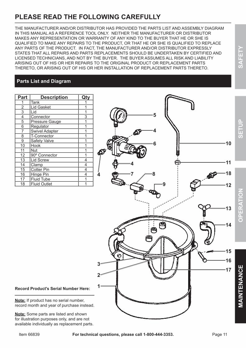
part Description Qty1 Tank 12 Lid Gasket 13 Lid 14 Connector 35 Pressure Gauge 16 Regulator 17 Swivel Adapter 18 T-Connector 19 Safety Valve 1
10 Hook 111 Nut 112 90º Connector 113 Lid Screw 414 Clamp 415 Cotter Pin 416 Hinge Pin 417 Fluid Tube 118 Fluid Outlet 1
pLEASE READ THE FOLLOWING cAREFULLyTHE MANUFACTURER AND/OR DISTRIBUTOR HAS PROVIDED THE PARTS LIST AND ASSEMBLY DIAGRAM IN THIS MANUAL AS A REFERENCE TOOL ONLY. NEITHER THE MANUFACTURER OR DISTRIBUTOR MAKES ANY REPRESENTATION OR WARRANTY OF ANY KIND TO THE BUYER THAT HE OR SHE IS QUALIFIED TO MAKE ANY REPAIRS TO THE PRODUCT, OR THAT HE OR SHE IS QUALIFIED TO REPLACE ANY PARTS OF THE PRODUCT. IN FACT, THE MANUFACTURER AND/OR DISTRIBUTOR EXPRESSLY STATES THAT ALL REPAIRS AND PARTS REPLACEMENTS SHOULD BE UNDERTAKEN BY CERTIFIED AND LICENSED TECHNICIANS, AND NOT BY THE BUYER. THE BUYER ASSUMES ALL RISK AND LIABILITY ARISING OUT OF HIS OR HER REPAIRS TO THE ORIGINAL PRODUCT OR REPLACEMENT PARTS THERETO, OR ARISING OUT OF HIS OR HER INSTALLATION OF REPLACEMENT PARTS THERETO.
parts List and Diagram
Record product's Serial Number Here: Note: If product has no serial number, record month and year of purchase instead.
Note: Some parts are listed and shown for illustration purposes only, and are not available individually as replacement parts.
4
1
5
4
10
11
18
12
13
14
15
16
17
6
4
7 8
9
2
3
Limited 90 Day Warranty
Harbor Freight Tools Co. makes every effort to assure that its products meet high quality and durability standards, and warrants to the original purchaser that this product is free from defects in materials and workmanship for the period of 90 days from the date of purchase. This warranty does not apply to damage due directly or indirectly, to misuse, abuse, negligence or accidents, repairs or alterations outside our facilities, criminal activity, improper installation, normal wear and tear, or to lack of maintenance. We shall in no event be liable for death, injuries to persons or property, or for incidental, contingent, special or consequential damages arising from the use of our product. Some states do not allow the exclusion or limitation of incidental or consequential damages, so the above limitation of exclusion may not apply to you. THIS WARRANTY IS EXPRESSLY IN LIEU OF ALL OTHER WARRANTIES, EXPRESS OR IMPLIED, INCLUDING THE WARRANTIES OF MERCHANTABILITY AND FITNESS.To take advantage of this warranty, the product or part must be returned to us with transportation charges prepaid. Proof of purchase date and an explanation of the complaint must accompany the merchandise. If our inspection verifies the defect, we will either repair or replace the product at our election or we may elect to refund the purchase price if we cannot readily and quickly provide you with a replacement. We will return repaired products at our expense, but if we determine there is no defect, or that the defect resulted from causes not within the scope of our warranty, then you must bear the cost of returning the product.This warranty gives you specific legal rights and you may also have other rights which vary from state to state.
3491 Mission Oaks Blvd. • PO Box 6009 • Camarillo, CA 93011 • (800) 444-3353